

Page 1
C
over Page
OPERATING MANUAL
STM-2XM
Rate and Thickness Monitor
PN 074-614-P1A
Page 2

Page 3

www.inficon.com reachus@inficon.com
©2014 INFICON
®
Title P
age
OPERATING MANUAL
STM-2XM
Rate and Thickness Monitor
PN 074-614-P1A
Page 4

Trademarks
The trademarks of the products mentioned in this manual are held by the companies that
produce them.
Windows® and Microsoft® are registered trademarks of Microsoft Corporation.
Inconel® is a registered trademark of Inco Alloys International, Huntington, WV.
LabVIEWTM is a trademark of National Instruments Corporation.
Sycon Instruments
All other brand and product names are trademarks or registered trademarks of their respective companies.
TM
is a trademark of INFICON,
Disclaimer
The information contained in this manual is believed to be accurate and reliable. However, INFICON assumes
no responsibility for its use and shall not be liable for any special, incidental, or consequential damages related
to the use of this product.
Due to our continuing program of product improvements, specifications are subject to change without notice.
Copyright
©2014 All rights reserved.
Reproduction or adaptation of any part of this document without permission is unlawful.
Page 5
Page 6

Page 7

Warranty
WARRANTY AND LIABILITY - LIMITATION: Seller warrants the products
manufactured by it, or by an affiliated company and sold by it, and described on
the reverse hereof, to be, for the period of warranty coverage specified below, free
from defects of materials or workmanship under normal proper use and service.
The period of warranty coverage is specified for the respective products in the
respective Seller instruction manuals for those products but shall not be less than
two (2) years from the date of shipment thereof by Seller. Seller's liability under
this warranty is limited to such of the above products or parts thereof as are
returned, transportation prepaid, to Seller's plant, not later than thirty (30) days
after the expiration of the period of warranty coverage in respect thereof and are
found by Seller's examination to have failed to function properly because of
defective workmanship or materials and not because of improper installation or
misuse and is limited to, at Seller's election, either (a) repairing and returning the
product or part thereof, or (b) furnishing a replacement product or part thereof,
transportation prepaid by Seller in either case. In the event Buyer discovers or
learns that a product does not conform to warranty, Buyer shall immediately notify
Seller in writing of such non-conformity, specifying in reasonable detail the nature
of such non-conformity. If Seller is not provided with such written notification,
Seller shall not be liable for any further damages which could have been avoided if
Seller had been provided with immediate written notification.
THIS WARRANTY IS MADE AND ACCEPTED IN LIEU OF ALL OTHER
WARRANTIES, EXPRESS OR IMPLIED, WHETHER OF MERCHANTABILITY OR
OF FITNESS FOR A PARTICULAR PURPOSE OR OTHERWISE, AS BUYER'S
EXCLUSIVE REMEDY FOR ANY DEFECTS IN THE PRODUCTS TO BE SOLD
HEREUNDER. All other obligations and liabilities of Seller, whether in contract or
tort (including negligence) or otherwise, are expressly EXCLUDED. In no event
shall Seller be liable for any costs, expenses or damages, whether direct or
indirect, special, incidental, consequential, or other, on any claim of any defective
product, in excess of the price paid by Buyer for the product plus return
transportation charges prepaid.
No warranty is made by Seller of any Seller product which has been installed,
used or operated contrary to Seller's written instruction manual or which has been
subjected to misuse, negligence or accident or has been repaired or altered by
anyone other than Seller or which has been used in a manner or for a purpose for
which the Seller product was not designed nor against any defects due to plans or
instructions supplied to Seller by or for Buyer.
This manual is intended for private use by INFICON® Inc. and its customers.
Contact INFICON before reproducing its contents.
NOTE: These instructions do not provide for every contingency that may arise in
connection with the installation, operation or maintenance of this equipment.
Should you require further assistance, please contact INFICON.
www.inficon.com reachus@inficon.com
Page 8

Page 9

STM-2XM Operating Manual
Table Of Contents
Cover Page
Title Page
Trademarks
Disclaimer
Copyright
Declaration Of Conformity
Warranty
Chapter 1
Introduction and Specifications
1.1 Introduction. . . . . . . . . . . . . . . . . . . . . . . . . . . . . . . . . . . . . . . . . . . . . . . . . . 1-1
1.1.1 Related Manuals. . . . . . . . . . . . . . . . . . . . . . . . . . . . . . . . . . . . . . . . . . . . . .1-2
1.2 Instrument Safety . . . . . . . . . . . . . . . . . . . . . . . . . . . . . . . . . . . . . . . . . . . . . 1-2
1.2.1 Definition of Notes, Cautions and Warnings. . . . . . . . . . . . . . . . . . . . . . . . .1-2
1.2.2 General Safety Information. . . . . . . . . . . . . . . . . . . . . . . . . . . . . . . . . . . . . . 1-3
1.2.3 Earth Ground . . . . . . . . . . . . . . . . . . . . . . . . . . . . . . . . . . . . . . . . . . . . . . . . 1-4
1.3 How To Contact INFICON . . . . . . . . . . . . . . . . . . . . . . . . . . . . . . . . . . . . . . 1-5
1.3.1 Returning STM-2XM. . . . . . . . . . . . . . . . . . . . . . . . . . . . . . . . . . . . . . . . . . .1-5
1.4 Specifications . . . . . . . . . . . . . . . . . . . . . . . . . . . . . . . . . . . . . . . . . . . . . . . . 1-6
1.4.1 Measurement . . . . . . . . . . . . . . . . . . . . . . . . . . . . . . . . . . . . . . . . . . . . . . . .1-6
1.4.2 Film Parameters . . . . . . . . . . . . . . . . . . . . . . . . . . . . . . . . . . . . . . . . . . . . . .1-6
1.4.3 System Parameters . . . . . . . . . . . . . . . . . . . . . . . . . . . . . . . . . . . . . . . . . . . 1-7
1.4.4 Digital I/O . . . . . . . . . . . . . . . . . . . . . . . . . . . . . . . . . . . . . . . . . . . . . . . . . . .1-7
1.4.5 Power . . . . . . . . . . . . . . . . . . . . . . . . . . . . . . . . . . . . . . . . . . . . . . . . . . . . . . 1-8
1.4.6 Operating Environment. . . . . . . . . . . . . . . . . . . . . . . . . . . . . . . . . . . . . . . . . 1-9
PN 074-614-P1A
1.4.7 Size and Weight . . . . . . . . . . . . . . . . . . . . . . . . . . . . . . . . . . . . . . . . . . . . . . 1-9
1.5 Unpacking and Inspection . . . . . . . . . . . . . . . . . . . . . . . . . . . . . . . . . . . . . .1-9
1.6 Parts and Options Overview. . . . . . . . . . . . . . . . . . . . . . . . . . . . . . . . . . . . .1-9
1.6.1 Base Configurations . . . . . . . . . . . . . . . . . . . . . . . . . . . . . . . . . . . . . . . . . . .1-9
1.6.2 Accessories . . . . . . . . . . . . . . . . . . . . . . . . . . . . . . . . . . . . . . . . . . . . . . . .1-10
1.6.3 Sensors . . . . . . . . . . . . . . . . . . . . . . . . . . . . . . . . . . . . . . . . . . . . . . . . . . . 1-11
TOC - 1
Page 10

STM-2XM Operating Manual
Chapter 2
Installation
2.1 Installation Requirements. . . . . . . . . . . . . . . . . . . . . . . . . . . . . . . . . . . . . . . 2-1
2.1.1 Parts Requirements . . . . . . . . . . . . . . . . . . . . . . . . . . . . . . . . . . . . . . . . . . . 2-1
2.1.2 Ground Requirements . . . . . . . . . . . . . . . . . . . . . . . . . . . . . . . . . . . . . . . . . 2-2
2.1.3 Connection to Earth Ground. . . . . . . . . . . . . . . . . . . . . . . . . . . . . . . . . . . . . 2-3
2.2 Rear Panel . . . . . . . . . . . . . . . . . . . . . . . . . . . . . . . . . . . . . . . . . . . . . . . . . . 2-3
2.2.1 Sensors . . . . . . . . . . . . . . . . . . . . . . . . . . . . . . . . . . . . . . . . . . . . . . . . . . . . 2-3
2.2.2 Relay Outputs. . . . . . . . . . . . . . . . . . . . . . . . . . . . . . . . . . . . . . . . . . . . . . . . 2-4
2.2.3 Analog Outputs. . . . . . . . . . . . . . . . . . . . . . . . . . . . . . . . . . . . . . . . . . . . . . . 2-5
2.2.4 Remote Inputs . . . . . . . . . . . . . . . . . . . . . . . . . . . . . . . . . . . . . . . . . . . . . . . 2-6
2.3 Basic Vacuum System Components . . . . . . . . . . . . . . . . . . . . . . . . . . . . . . 2-7
2.4 Deposition System Installation . . . . . . . . . . . . . . . . . . . . . . . . . . . . . . . . . . . 2-9
2.4.1 Sensor Head Installation . . . . . . . . . . . . . . . . . . . . . . . . . . . . . . . . . . . . . . . 2-9
Chapter 3
Operation
3.1 Front Panel Description . . . . . . . . . . . . . . . . . . . . . . . . . . . . . . . . . . . . . . . . 3-1
3.1.1 System Control Buttons . . . . . . . . . . . . . . . . . . . . . . . . . . . . . . . . . . . . . . . . 3-2
3.1.2 Data Entry and Programming Buttons . . . . . . . . . . . . . . . . . . . . . . . . . . . . . 3-3
3.1.3 Changing a Parameter . . . . . . . . . . . . . . . . . . . . . . . . . . . . . . . . . . . . . . . . . 3-4
3.1.4 Runtime Screen . . . . . . . . . . . . . . . . . . . . . . . . . . . . . . . . . . . . . . . . . . . . . . 3-6
3.2 Programming . . . . . . . . . . . . . . . . . . . . . . . . . . . . . . . . . . . . . . . . . . . . . . . . 3-7
3.2.1 Main Menu . . . . . . . . . . . . . . . . . . . . . . . . . . . . . . . . . . . . . . . . . . . . . . . . . . 3-7
3.2.1.1 Edit Film . . . . . . . . . . . . . . . . . . . . . . . . . . . . . . . . . . . . . . . . . . . . . . . . . . . . 3-8
3.2.1.2 System Settings . . . . . . . . . . . . . . . . . . . . . . . . . . . . . . . . . . . . . . . . . . . . . 3-10
3.2.1.3 Setup Parameters . . . . . . . . . . . . . . . . . . . . . . . . . . . . . . . . . . . . . . . . . . . 3-12
TOC - 2
3.3 STM-2XM Operating Modes. . . . . . . . . . . . . . . . . . . . . . . . . . . . . . . . . . . . 3-17
3.3.1 Simple . . . . . . . . . . . . . . . . . . . . . . . . . . . . . . . . . . . . . . . . . . . . . . . . . . . . 3-17
3.3.2 Backup . . . . . . . . . . . . . . . . . . . . . . . . . . . . . . . . . . . . . . . . . . . . . . . . . . . . 3-18
3.3.3 Averaging . . . . . . . . . . . . . . . . . . . . . . . . . . . . . . . . . . . . . . . . . . . . . . . . . . 3-19
3.3.4 Alloy . . . . . . . . . . . . . . . . . . . . . . . . . . . . . . . . . . . . . . . . . . . . . . . . . . . . . . 3-20
3.3.5 Independent . . . . . . . . . . . . . . . . . . . . . . . . . . . . . . . . . . . . . . . . . . . . . . . . 3-21
3.4 Operation . . . . . . . . . . . . . . . . . . . . . . . . . . . . . . . . . . . . . . . . . . . . . . . . . . 3-22
3.4.1 No Shutter Delay . . . . . . . . . . . . . . . . . . . . . . . . . . . . . . . . . . . . . . . . . . . . 3-22
3.4.2 Shutter Delay . . . . . . . . . . . . . . . . . . . . . . . . . . . . . . . . . . . . . . . . . . . . . . . 3-22
3.4.3 Test Mode . . . . . . . . . . . . . . . . . . . . . . . . . . . . . . . . . . . . . . . . . . . . . . . . . 3-22
3.4.4 Rate Sampling . . . . . . . . . . . . . . . . . . . . . . . . . . . . . . . . . . . . . . . . . . . . . . 3-23
3.5 Film States . . . . . . . . . . . . . . . . . . . . . . . . . . . . . . . . . . . . . . . . . . . . . . . . . 3-23
PN 074-614-P1A
Page 11

STM-2XM Operating Manual
Chapter 4
Software
4.1 Introduction. . . . . . . . . . . . . . . . . . . . . . . . . . . . . . . . . . . . . . . . . . . . . . . . . . 4-1
4.2 Installing INFICON STM-2XM FilmMaker Software . . . . . . . . . . . . . . . . . . .4-1
4.2.1 Installing the Protocol Server . . . . . . . . . . . . . . . . . . . . . . . . . . . . . . . . . . . . 4-1
4.2.2 Installing INFICON STM-2XM FilmMaker Software . . . . . . . . . . . . . . . . . . .4-2
4.2.3 Starting INFICON STM-2XM FilmMaker Software . . . . . . . . . . . . . . . . . . . . 4-3
4.2.3.1 Starting the Software in Windows XP or Windows 7 . . . . . . . . . . . . . . . . . . 4-3
4.2.3.2 Starting the Software in Windows 8 . . . . . . . . . . . . . . . . . . . . . . . . . . . . . . .4-3
4.3 STM-2XM Parameter Manager . . . . . . . . . . . . . . . . . . . . . . . . . . . . . . . . . . 4-4
4.3.1 Main Tab. . . . . . . . . . . . . . . . . . . . . . . . . . . . . . . . . . . . . . . . . . . . . . . . . . . .4-5
4.3.1.1 Main Setup Pane . . . . . . . . . . . . . . . . . . . . . . . . . . . . . . . . . . . . . . . . . . . . .4-5
4.3.1.2 Utilities Pane. . . . . . . . . . . . . . . . . . . . . . . . . . . . . . . . . . . . . . . . . . . . . . . . .4-7
4.3.2 Films Tab . . . . . . . . . . . . . . . . . . . . . . . . . . . . . . . . . . . . . . . . . . . . . . . . . . .4-8
4.3.3 System Tab . . . . . . . . . . . . . . . . . . . . . . . . . . . . . . . . . . . . . . . . . . . . . . . . 4-10
4.3.3.1 Setup parameters Pane . . . . . . . . . . . . . . . . . . . . . . . . . . . . . . . . . . . . . . .4-11
4.3.3.2 System parameters Pane. . . . . . . . . . . . . . . . . . . . . . . . . . . . . . . . . . . . . . 4-16
4.3.4 Save/Load file Tab . . . . . . . . . . . . . . . . . . . . . . . . . . . . . . . . . . . . . . . . . . .4-17
4.3.5 Save/Load instrument Tab . . . . . . . . . . . . . . . . . . . . . . . . . . . . . . . . . . . . . 4-18
4.3.6 About Tab . . . . . . . . . . . . . . . . . . . . . . . . . . . . . . . . . . . . . . . . . . . . . . . . . . 4-20
Chapter 5
Communications
5.1 Introduction. . . . . . . . . . . . . . . . . . . . . . . . . . . . . . . . . . . . . . . . . . . . . . . . . . 5-1
5.2 Communications Connections . . . . . . . . . . . . . . . . . . . . . . . . . . . . . . . . . . .5-1
5.2.1 RS-232/RS-485 Connector. . . . . . . . . . . . . . . . . . . . . . . . . . . . . . . . . . . . . . 5-1
5.2.2 RS-232 Point-to-Point Mode. . . . . . . . . . . . . . . . . . . . . . . . . . . . . . . . . . . . . 5-2
5.2.3 RS-485 TTL Differential Signaling Mode . . . . . . . . . . . . . . . . . . . . . . . . . . . 5-2
5.3 Electrical. . . . . . . . . . . . . . . . . . . . . . . . . . . . . . . . . . . . . . . . . . . . . . . . . . . . 5-3
PN 074-614-P1A
5.3.1 RS-485 Line Signal. . . . . . . . . . . . . . . . . . . . . . . . . . . . . . . . . . . . . . . . . . . .5-4
5.3.2 Bit Time . . . . . . . . . . . . . . . . . . . . . . . . . . . . . . . . . . . . . . . . . . . . . . . . . . . . 5-4
5.4 Bauds . . . . . . . . . . . . . . . . . . . . . . . . . . . . . . . . . . . . . . . . . . . . . . . . . . . . . . 5-4
5.5 Message Format. . . . . . . . . . . . . . . . . . . . . . . . . . . . . . . . . . . . . . . . . . . . . .5-4
5.5.1 Sycon Protocol . . . . . . . . . . . . . . . . . . . . . . . . . . . . . . . . . . . . . . . . . . . . . . . 5-4
5.5.1.1 Command Format. . . . . . . . . . . . . . . . . . . . . . . . . . . . . . . . . . . . . . . . . . . . .5-5
5.5.2 Sycon Multi-Drop Protocol (SMDP) . . . . . . . . . . . . . . . . . . . . . . . . . . . . . . .5-6
5.5.2.1 Command Format. . . . . . . . . . . . . . . . . . . . . . . . . . . . . . . . . . . . . . . . . . . . .5-6
5.5.2.1.1 Checksum. . . . . . . . . . . . . . . . . . . . . . . . . . . . . . . . . . . . . . . . . . . . . . . . . . .5-9
5.5.2.1.2 Command Packet Format. . . . . . . . . . . . . . . . . . . . . . . . . . . . . . . . . . . . . .5-10
5.5.2.1.3 Response Packet Format. . . . . . . . . . . . . . . . . . . . . . . . . . . . . . . . . . . . . . 5-11
TOC - 3
Page 12

STM-2XM Operating Manual
5.5.3 Optional Serial Command Mode . . . . . . . . . . . . . . . . . . . . . . . . . . . . . . . . 5-11
5.5.3.1 Optional Serial Command Format . . . . . . . . . . . . . . . . . . . . . . . . . . . . . . . 5-12
5.5.3.2 Additional Option to Serial Command . . . . . . . . . . . . . . . . . . . . . . . . . . . . 5-12
5.6 Communication Library . . . . . . . . . . . . . . . . . . . . . . . . . . . . . . . . . . . . . . . 5-13
5.6.1 Methods . . . . . . . . . . . . . . . . . . . . . . . . . . . . . . . . . . . . . . . . . . . . . . . . . . . 5-14
5.6.2 Communication Properties . . . . . . . . . . . . . . . . . . . . . . . . . . . . . . . . . . . . . 5-15
5.6.3 Other Properties . . . . . . . . . . . . . . . . . . . . . . . . . . . . . . . . . . . . . . . . . . . . . 5-15
5.7 Windows/SMDP Server Implementation . . . . . . . . . . . . . . . . . . . . . . . . . . 5-16
5.8 Communications Commands . . . . . . . . . . . . . . . . . . . . . . . . . . . . . . . . . . . 5-17
5.8.1 Command: ?. . . . . . . . . . . . . . . . . . . . . . . . . . . . . . . . . . . . . . . . . . . . . . . . 5-18
5.8.2 Command: @ . . . . . . . . . . . . . . . . . . . . . . . . . . . . . . . . . . . . . . . . . . . . . . . 5-18
5.8.3 Command: C . . . . . . . . . . . . . . . . . . . . . . . . . . . . . . . . . . . . . . . . . . . . . . . 5-18
5.8.4 Command: E/F . . . . . . . . . . . . . . . . . . . . . . . . . . . . . . . . . . . . . . . . . . . . . . 5-20
5.8.4.1 Analog Output Function . . . . . . . . . . . . . . . . . . . . . . . . . . . . . . . . . . . . . . . 5-24
5.8.4.2 Relay Functions . . . . . . . . . . . . . . . . . . . . . . . . . . . . . . . . . . . . . . . . . . . . . 5-26
5.8.4.3 Input Functions. . . . . . . . . . . . . . . . . . . . . . . . . . . . . . . . . . . . . . . . . . . . . . 5-27
5.8.5 Command: G/H . . . . . . . . . . . . . . . . . . . . . . . . . . . . . . . . . . . . . . . . . . . . . 5-28
5.8.6 Command: I/J . . . . . . . . . . . . . . . . . . . . . . . . . . . . . . . . . . . . . . . . . . . . . . . 5-28
5.8.7 Command: K/L . . . . . . . . . . . . . . . . . . . . . . . . . . . . . . . . . . . . . . . . . . . . . . 5-30
5.8.8 Command: M/N . . . . . . . . . . . . . . . . . . . . . . . . . . . . . . . . . . . . . . . . . . . . . 5-30
5.8.9 Command: O . . . . . . . . . . . . . . . . . . . . . . . . . . . . . . . . . . . . . . . . . . . . . . . 5-31
5.8.10 Command: P . . . . . . . . . . . . . . . . . . . . . . . . . . . . . . . . . . . . . . . . . . . . . . . 5-32
5.8.10.1 Alloy State Class . . . . . . . . . . . . . . . . . . . . . . . . . . . . . . . . . . . . . . . . . . . . 5-33
5.8.11 Command: Q . . . . . . . . . . . . . . . . . . . . . . . . . . . . . . . . . . . . . . . . . . . . . . . 5-34
5.8.11.1 Raw Status. . . . . . . . . . . . . . . . . . . . . . . . . . . . . . . . . . . . . . . . . . . . . . . . . 5-36
5.8.11.2 Raw Status 2 . . . . . . . . . . . . . . . . . . . . . . . . . . . . . . . . . . . . . . . . . . . . . . . 5-36
5.8.11.3 Film State . . . . . . . . . . . . . . . . . . . . . . . . . . . . . . . . . . . . . . . . . . . . . . . . . . 5-37
5.8.12 Run Screen Lock Codes and Functions. . . . . . . . . . . . . . . . . . . . . . . . . . . 5-38
5.8.13 Command Examples . . . . . . . . . . . . . . . . . . . . . . . . . . . . . . . . . . . . . . . . . 5-39
5.8.13.1 Query Software Version . . . . . . . . . . . . . . . . . . . . . . . . . . . . . . . . . . . . . . . 5-39
5.8.13.2 Reboot SMDP Device . . . . . . . . . . . . . . . . . . . . . . . . . . . . . . . . . . . . . . . . 5-40
Chapter 6
Troubleshooting
6.1 Troubleshooting Guide. . . . . . . . . . . . . . . . . . . . . . . . . . . . . . . . . . . . . . . . . 6-1
6.2 Maintenance. . . . . . . . . . . . . . . . . . . . . . . . . . . . . . . . . . . . . . . . . . . . . . . . . 6-7
6.3 Spare Parts . . . . . . . . . . . . . . . . . . . . . . . . . . . . . . . . . . . . . . . . . . . . . . . . . 6-7
6.4 Persistent Crystal Fail Indication . . . . . . . . . . . . . . . . . . . . . . . . . . . . . . . . . 6-7
6.5 Diagnostics Menu. . . . . . . . . . . . . . . . . . . . . . . . . . . . . . . . . . . . . . . . . . . . . 6-8
PN 074-614-P1A
TOC - 4
Page 13

Chapter 7
7.1 Importance of Density, Tooling and Z-Ratio. . . . . . . . . . . . . . . . . . . . . . . . . 7-1
7.2 Determining Density . . . . . . . . . . . . . . . . . . . . . . . . . . . . . . . . . . . . . . . . . . .7-1
7.3 Determining Tooling . . . . . . . . . . . . . . . . . . . . . . . . . . . . . . . . . . . . . . . . . . . 7-2
7.4 Laboratory Determination of Z-Ratio . . . . . . . . . . . . . . . . . . . . . . . . . . . . . .7-3
Chapter 8
8.1 Basics. . . . . . . . . . . . . . . . . . . . . . . . . . . . . . . . . . . . . . . . . . . . . . . . . . . . . . 8-1
8.1.1 Monitor Crystals . . . . . . . . . . . . . . . . . . . . . . . . . . . . . . . . . . . . . . . . . . . . . .8-2
8.1.2 Period Measurement Technique . . . . . . . . . . . . . . . . . . . . . . . . . . . . . . . . . 8-4
8.1.3 Z-match Technique. . . . . . . . . . . . . . . . . . . . . . . . . . . . . . . . . . . . . . . . . . . .8-6
Appendix A
A.1 Introduction. . . . . . . . . . . . . . . . . . . . . . . . . . . . . . . . . . . . . . . . . . . . . . . . . .A-1
STM-2XM Operating Manual
Calibration Procedures
Measurement and Theory
Material Table
PN 074-614-P1A
TOC - 5
Page 14

STM-2XM Operating Manual
This page is intentionally blank.
TOC - 6
PN 074-614-P1A
Page 15
1.1 Introduction
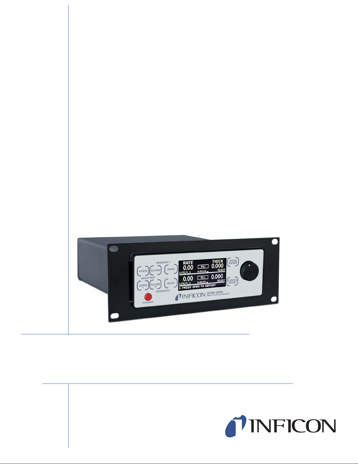
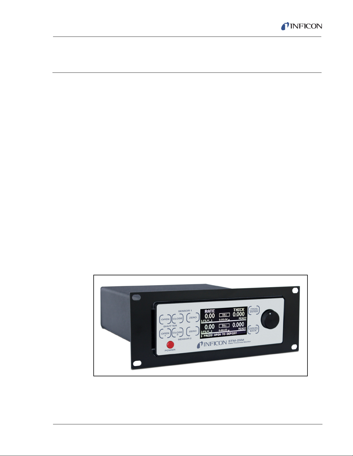
STM-2XM rate and thickness monitor (see Figure 1-1) will manage single sensor
processes as well as codeposition and alloy processes through five modes of
operation:
Simple mode (single film mode)
Backup mode (crystal switching)
Averaging mode
Alloy mode
Independent mode
Independent mode allows STM-2XM to function as two completely separate
monitors with shutter delay. To extend crystal life for thicker films, the Alloy mode
provides a linked shutter delay.
STM-2XM Operating Manual
Chapter 1
Introduction and Specifications
Time/Power allows films to complete even with a crystal failure. STM-2XM displays
accumulated film mass or thickness and can also display a graph of rate, thickness,
or rate deviation.
STM-2XM has eight programmable digital inputs, eight programmable digital
outputs, and four analog outputs.
Figure 1-1 STM-2XM rate/thickness monitor
PN 074-614-P1A
1 - 1
Page 16
STM-2XM Operating Manual
CAUTION
WARNING
WARNING - Risk Of Electric Shock
1.1.1 Related Manuals
Sensors are covered in separate manuals. PDF files of these manuals are
contained in the Thin Film Manuals CD (PN 074-5000-G1), part of the Ship Kit.
PN 074-154—Bakeable Sensor
PN 074-156—Front Load Sensor, Single/Dual
PN 074-157—Sputtering Sensor
PN 074-609—Cool Drawer Sensor, Single/Dual
1.2 Instrument Safety
1.2.1 Definition of Notes, Cautions and Warnings
When using this manual, please pay attention to the NOTES, CAUTIONS, and
WARNINGS found throughout. For the purposes of this manual they are defined as
follows:
NOTE: Pertinent information that is useful in achieving maximum STM-2XM
efficiency when followed.
Failure to heed these messages could result in damage
to STM-2XM.
Failure to heed these messages could result in personal
injury.
Dangerous voltages are present which could result in
personal injury.
PN 074-614-P1A
1 - 2
Page 17

1.2.2 General Safety Information
WARNING - Risk Of Electric Shock
CAUTION
Dangerous voltages may be present whenever the power
cord or external input/relay connectors are present.
Refer all maintenance to qualified personnel.
STM-2XM contains delicate circuitry which is susceptible
to transient power line voltages. Disconnect the line cord
whenever making any interface connections. Refer all
maintenance to qualified personnel.
STM-2XM Operating Manual
PN 074-614-P1A
1 - 3
Page 18
STM-2XM Operating Manual
WARNING - Risk Of Electric Shock
CAUTION
1.2.3 Earth Ground
STM-2XM is connected to earth ground through a sealed three-core
(three-conductor) power cable, which must be plugged into a socket outlet with a
protective earth terminal. Extension cables must always have three conductors
including a protective earth terminal.
Never interrupt the protective earth circuit.
Any interruption of the protective earth circuit inside or
outside STM-2XM, or disconnection of the protective
earth terminal is likely to make STM-2XM dangerous.
This symbol indicates where the protective earth ground
is connected inside STM-2XM. Never unscrew or loosen
this connection.
There are no user serviceable components within the
STM-2XM case.
Refer all maintenance to qualified personnel.
PN 074-614-P1A
1 - 4
Page 19

1.3 How To Contact INFICON
Worldwide customer support information is available under Support >> Support
Worldwide at www.inficon.com:
Sales and Customer Service
Technical Support
Repair Service
If experiencing a problem with STM-2XM, please have the following information
readily available:
The Sales Order or Purchase Order number of the instrument purchase.
The version of STM-2XM firmware.
The version of Windows operating system.
A description of the problem.
An explanation of any corrective action that may have already been attempted.
The exact wording of any error messages that may have been received.
STM-2XM Operating Manual
1.3.1 Returning STM-2XM
Do not return any component of STM-2XM to INFICON before speaking with a
Customer Support Representative and obtaining a Return Material Authorization
(RMA) number. STM-2XM will not be serviced without an RMA number.
Packages delivered to INFICON without an RMA number will be held until the
customer is contacted. This will result in delays in servicing STM-2XM.
If returning STM-2XM with a crystal sensor or another component potentially
exposed to process materials, prior to being given an RMA number, a completed
Declaration Of Contamination (DOC) form will be required. DOC forms must be
approved by INFICON before an RMA number is issued. INFICON may require
PN 074-614-P1A
that the component be sent to a designated decontamination facility, not to the
factory.
1 - 5
Page 20

STM-2XM Operating Manual
1.4 Specifications
1.4.1 Measurement
Sensor Inputs . . . . . . . . . . . . . . . . . . 2
Compatible Sensors. . . . . . . . . . . . . Single/shuttered single or dual QCM sensor
Measurement Frequency Range . . . 6.0 to 5.0 MHz (fixed)
Frequency Resolution . . . . . . . . . . . ± 0.03 Hz @ 6 MHz
Reference Frequency Stability . . . . . ± 2 ppm
Thickness and Rate
Resolution/Measurement . . . . . . . . . ± 0.037 Å @ tooling/density = 100/1
Measurement Interval . . . . . . . . . . . 0.10 s
1.4.2 Film Parameters
Stored Films . . . . . . . . . . . . . . . . . . . 15
Fundamental frequency = 6 MHz
Name . . . . . . . . . . . . . . . . . . . . . . . . 8 characters, 0 to 9, A to Z, _ and [space]
Density . . . . . . . . . . . . . . . . . . . . . . . 0.4 to 99.99 g/cm
3
Z-Ratio . . . . . . . . . . . . . . . . . . . . . . . 0.100 to 9.999
Tooling . . . . . . . . . . . . . . . . . . . . . . . 10 to 999.9%
Setpoint Thickness. . . . . . . . . . . . . . 0.000 to 999.999 kÅ
End Thickness . . . . . . . . . . . . . . . . . 0.000 to 999.999 kÅ
Use Backup Crystal . . . . . . . . . . . . . Yes/No
Setpoint Time . . . . . . . . . . . . . . . . . . 0:00:00 to 9:59:59 h:mm:ss
Deposit Rate . . . . . . . . . . . . . . . . . . 0.0 to 999.9 Å/s
Coast Enable . . . . . . . . . . . . . . . . . . Yes/No
Crystal Life Minimum . . . . . . . . . . . . 0 to 99%
Force Crystal Fail . . . . . . . . . . . . . . . Yes/No
Temporal Average . . . . . . . . . . . . . . 1 to 50
Good Rate Tolerance . . . . . . . . . . . . 0 to 50
PN 074-614-P1A
1 - 6
Page 21

1.4.3 System Parameters
Operation Modes . . . . . . . . . . . . . . . Simple mode (single film mode)
Test Mode. . . . . . . . . . . . . . . . . . . . . On/Off
Active Source . . . . . . . . . . . . . . . . . . Channel 1/Channel 2
Display Mode . . . . . . . . . . . . . . . . . . Thickness/Mass
Plot Type . . . . . . . . . . . . . . . . . . . . . None/Rate Deviation/Rate/Thickness
Plot Time Interval . . . . . . . . . . . . . . . 0:00:00 to 9:59:59 h:mm:ss
LCD Contrast . . . . . . . . . . . . . . . . . . 10 to 85
LCD Brightness . . . . . . . . . . . . . . . . 1 to 99
Beeper . . . . . . . . . . . . . . . . . . . . . . . On/Off
STM-2XM Operating Manual
Backup mode (crystal switching)
Averaging mode
Alloy mode
Independent mode
Communications Protocol . . . . . . . . Sycon 9600 (Sycon Protocol @ 9.6 Kbps)
SMDP L (SMDP Protocol @ 9.6 Kbps)
SMDP M (SMDP Protocol @ 38.4 Kbps)
SMDP H (SMDP Protocol @ 115.2 Kbps)
SMDP Address. . . . . . . . . . . . . . . . . 16 to 254
1.4.4 Digital I/O
Digital Inputs. . . . . . . . . . . . . . . . . . . 8
Digital Input Functions . . . . . . . . . . . Open Shutter
Close Shutter
Zero Thickness
PN 074-614-P1A
Disabled
Select crystal as active (dual mode)
NOTE: To select crystal one, use on a
Channel 1 input (1.x). To select
crystal two, use on a Channel 2 input
(2.x).
Allow sync
Digital Outputs . . . . . . . . . . . . . . . . . 8
NOTE: Allows simultaneous shutter delay of
both films.
1 - 7
Page 22

STM-2XM Operating Manual
Digital Output Functions. . . . . . . . . . Manual (front panel)
Source shutter
Substrate shutter
Sensor shutter
Crystal fail
Setpoint time
Setpoint thick
Forced active
Controlled via serial communications
Rate is steady and within tolerance
Analog Outputs. . . . . . . . . . . . . . . . . 4
Analog Output Functions . . . . . . . . . Rate:
Rate 1000 Å/s, 10.00 µg scale
Rate 10.0 Å/s, 0.10 µg scale
Rate deviation:
Rate deviation 1000 Å/s, 10.00 µg scale
Rate deviation 10.0 Å/s, 0.10 µg scale
1.4.5 Power
Thickness:
Thickness recorder 999 Å scale
Thickness recorder 99.9 Å scale
Disabled
Controlled via serial communications
Fixed positive/negative full scale
Analog Output Rating. . . . . . . . . . . . -10 to +10 V, 10 mA
Relay Rating. . . . . . . . . . . . . . . . . . . up to 48 V (dc)
• V (ac), 2 A
Rated Supply Voltage. . . . . . . . . . . . 100 to 240 V (ac) ± 10%, 50/60 Hz, 2.5 VA
Fuse Rating . . . . . . . . . . . . . . . . . . . 1 A 250 V, 5 x 20 mm, Fast-acting
Mains Power Cable Rating
STM-2XM-G1 . . . . . . . . . . . . . . . 10 A 125 V
STM-2XM-G2 . . . . . . . . . . . . . . . 10 A 250 V
Power Consumption. . . . . . . . . . . . . less than 10 W
PN 074-614-P1A
1 - 8
Overvoltage . . . . . . . . . . . . . . . . . . . Category II
Temporary Overvoltage
Short Term . . . . . . . . . . . . . . . . . 1200 V, < 5 s
Long Term . . . . . . . . . . . . . . . . . 250 V, > 5 s
Page 23

1.4.6 Operating Environment
Usage . . . . . . . . . . . . . . . . . . . . . . . . Indoor use only
Operating Temperature . . . . . . . . . . 0 to 50°C (32 to 122°F)
Storage Temperature . . . . . . . . . . . . -10 to 60°C (14 to 140°F)
Humidity . . . . . . . . . . . . . . . . . . . . . . Up to 85% RH, non-condensing
Altitude . . . . . . . . . . . . . . . . . . . . . . . Up to 2000 meters
Pollution Degree. . . . . . . . . . . . . . . . 2
1.4.7 Size and Weight
Rack Dimensions (HxWxD) . . . . . . . 8.9 x 24.1 x 25.4 cm (3.5 x 9.5 x 10 in.)
Weight . . . . . . . . . . . . . . . . . . . . . . . 1.25 kg (2.75 lb.)
1.5 Unpacking and Inspection
1 If STM-2XM has not been removed from its packaging, do so now.
STM-2XM Operating Manual
2 Carefully examine STM-2XM for damage that may have occurred during
shipping. It is especially important to note obvious rough handling on the
outside of the container. Immediately report any damage to the carrier and to
INFICON.
3 Do not discard the packaging material until inventory has been taken and
installation has been successful.
4 Refer to the invoice to take inventory (see section 1.6).
5 To install STM-2XM, see Chapter 2, Installation.
6 For additional information or technical assistance, contact INFICON (refer to
section 1.3 on page 1-5).
PN 074-614-P1A
1.6 Parts and Options Overview
1.6.1 Base Configurations
STM-2XM with US Power Cord . . . . PN STM-2XM-G1
STM-2XM with
European Power Cord . . . . . . . . . . . PN STM-2XM-G2
Thin Film Manuals CD . . . . . . . . . . . PN 074-5000-G1
1 - 9
Page 24

STM-2XM Operating Manual
1.6.2 Accessories
3 m (10 ft.) Oscillator Kit. . . . . . . . . . PN 783-500-109-10
7.6 m (25 ft.) Oscillator Kit . . . . . . . . PN 783-500-109-25
15.2 m (50 ft.) Oscillator Kit . . . . . . . PN 783-500-109-50
22.9 m (75 ft.) Oscillator Kit . . . . . . . PN 783-500-109-75
NOTE: Each sensor requires an oscillator kit to interface to STM-2XM.
Oscillator kits include:
Oscillator . . . . . . . . . . . . . . . . . . PN 783-500-013
15.2 cm (6 in.) BNC cable . . . . . PN 782-902-011
One of the following:
3 m (10 ft.) BNC Cable . . . . . PN 782-902-012-10
7.6 m (25 ft.) BNC Cable . . . PN 782-902-012-25
15.2 m (50 ft.) BNC Cable . . PN 782-902-012-50
22.9 m (75 ft.) BNC Cable . . PN 782-902-012-75
These kits are designed for use with the standard in-vacuum cables ranging in
length from 15.2 cm (6 in.) to 78.1 cm (30.75 in.).
48.3 cm (19 in.) rack mount kits are available in the following configurations:
One STM-2XM . . . . . . . . . . . . . . PN 783-014-008
Two STM-2XM . . . . . . . . . . . . . . PN 783-014-009
PN 074-614-P1A
1 - 10
Page 25

1.6.3 Sensors
Front Load Single Sensor. . . . . . . . . . . . . . . . . . . . . PN SL-XXXXX
Front Load Dual Sensor . . . . . . . . . . . . . . . . . . . . . . PN DL-AXXX
Cool Drawer Single Sensor . . . . . . . . . . . . . . . . . . .PN CDS-XXFXX
Cool Drawer Dual Sensor. . . . . . . . . . . . . . . . . . . . . PN CDD-XFXX
Sputtering Sensor. . . . . . . . . . . . . . . . . . . . . . . . . . . PN 750-618-G1
UHV Bakeable Sensor . . . . . . . . . . . . . . . . . . . . . . .PN BK-AXF
Low Profile Single Sensor . . . . . . . . . . . . . . . . . . . . PN 783-500-042
Low Profile Dual Sensor. . . . . . . . . . . . . . . . . . . . . .PN 783-500-093
Low Profile Bakeable Single Sensor . . . . . . . . . . . . PN 783-500-009
Low Profile Bakeable Dual Sensor. . . . . . . . . . . . . . PN 783-500-050
NOTE: Low Profile Sensors also have shuttered options as well as options without
NOTE: "X" in part number indicates customer-selectable option, see
STM-2XM Operating Manual
cooling lines.
www.inficon.com for Sensor Datasheets.
NOTE: Shuttered sensors require a feedthrough with an air line and solenoid valve
PN 750-420-G1.
NOTE: Multi-crystal (rotary) sensors should not be used with STM-2XM.
PN 074-614-P1A
1 - 11
Page 26

STM-2XM Operating Manual
This page is intentionally blank.
1 - 12
PN 074-614-P1A
Page 27
2.1 Installation Requirements
CAUTION
CAUTION
2.1.1 Parts Requirements
STM-2XM Monitor
Use the supplied mains power cable.
If this cable must be replaced, the replacement cable
must meet or exceed the ratings of the supplied cable.
STM-2XM Operating Manual
Chapter 2
Installation
One crystal sensor/feedthrough
One Oscillator Kit for each crystal sensor
Quartz crystals appropriate for the application
To maintain proper STM-2XM performance, use only
the 15.2 cm (6 in.) BNC cable that is included to connect
the oscillator to the crystal sensor.
The length of the in-vacuum cable (Front Load and
Sputtering sensors) or electrical conduit tube
(Cool Drawer and Bakeable sensors) should not exceed
PN 074-614-P1A
78.1 cm (30.75 in.).
2 - 1
Page 28
STM-2XM Operating Manual
CAUTION
Substrate
Source
Sensor
Evaporator
Power Supply
2.4 m (8 ft.) Copper Ground Rods
7.62 cm (3 in.)
Wide Copper
Ground
Strap
12.7 mm (0.5 in.)
Wide Copper
Ground
Straps
Earth
2.1.2 Ground Requirements
A ground post is provided on the rear panel. This point
should be connected to the common ground with a
grounding strap.
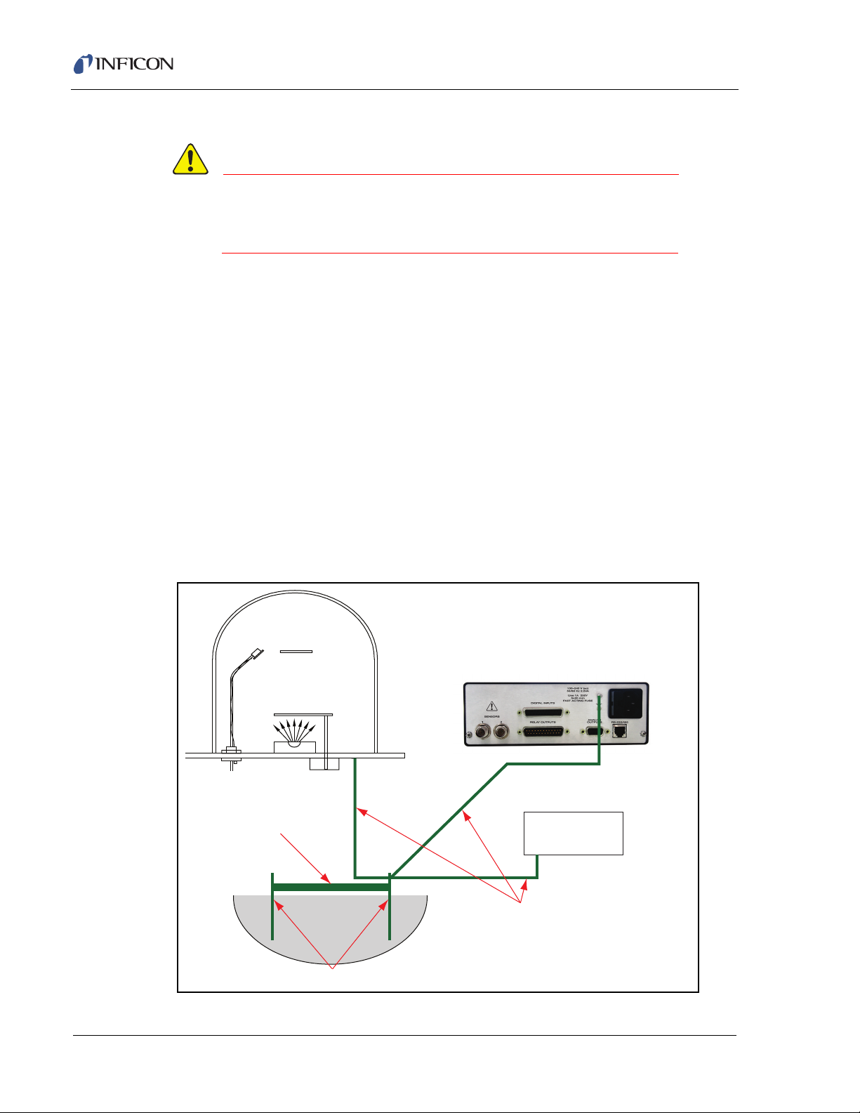
Use low impedance cables or straps to connect the chassis of all control
components to a common ground point on the vacuum chamber. The common
ground point must be connected to earth ground (see section 2.1.3, Connection to
Earth Ground, on page 2-3).
Solid copper straps are recommended, where RF is present. Use a strap of the
shortest possible length, minimum width of 12.7 mm (0.5 in.), approximately
0.56 mm (0.22 in.) thick. This is particularly important in high-noise electron beam
(e-beam) systems. See Figure 2-1 for the recommended grounding method.
NOTE: The oscillator is grounded to STM-2XM and crystal sensor through the
BNC cables.
The crystal sensor is typically grounded to the wall of the vacuum system. If the
sensor feedthrough is not properly grounded to earth through the vacuum system,
connect a copper strap between the feedthrough and the common ground point on
the vacuum system.
Figure 2-1 Recommended grounding
PN 074-614-P1A
2 - 2
Page 29
2.1.3 Connection to Earth Ground
CAUTION
If an earth ground is not established:
1 Where soil conditions allow, drive two 2.4 m (8 ft.) copper clad steel rods into
the ground 1.8 m (6 ft.) apart. Follow local regulations and codes.
2 Pour a copper sulfate or a salt solution around each rod to improve the
ground conductivity.
3 Measure the resistance. A near zero resistance between the two rods indicates
that a good earth ground is achieved.
4 After verifying a near zero resistance between the rods, connect the rods
together with a 7.62 cm (3 in.) wide copper strap.
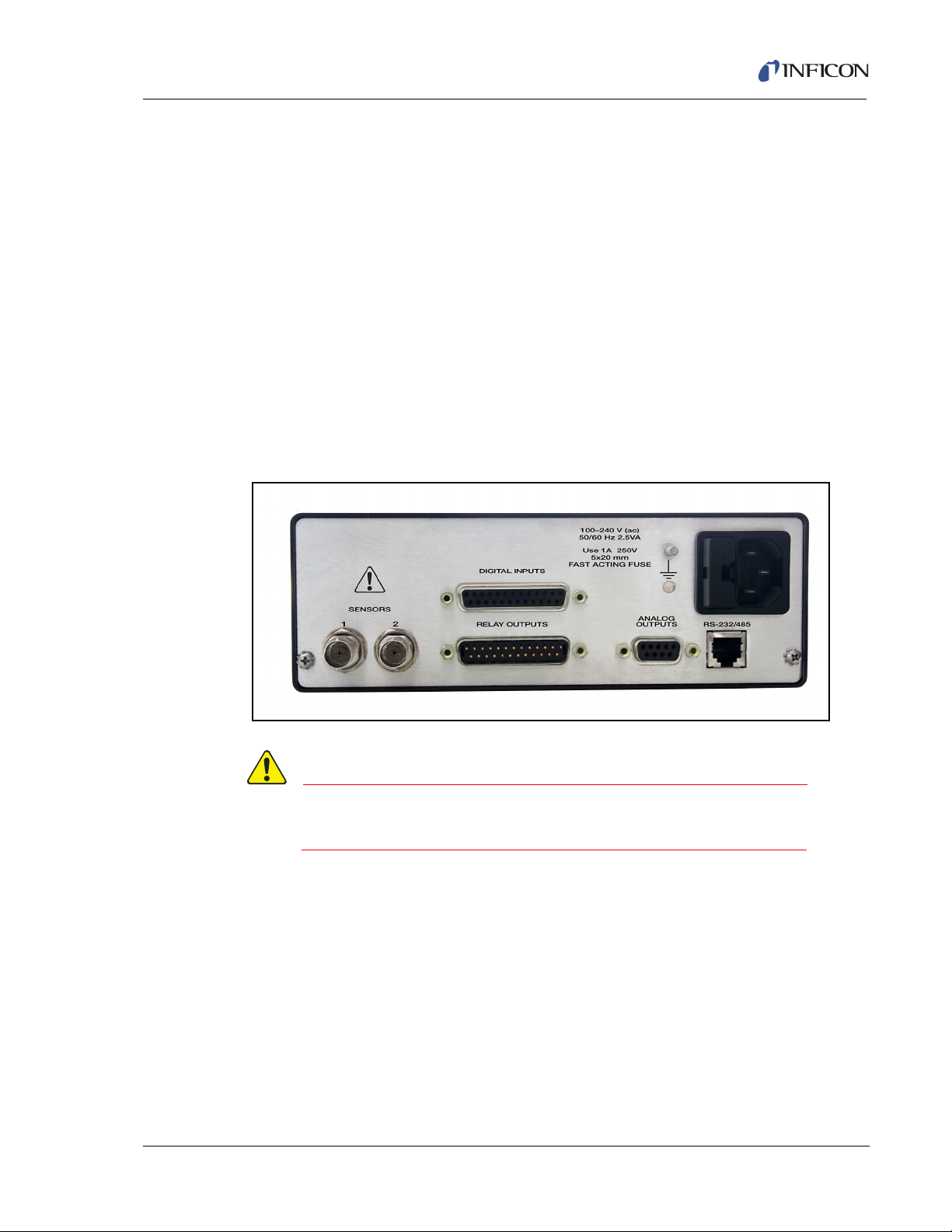
2.2 Rear Panel
Figure 2-2 STM-2XM rear panel
STM-2XM Operating Manual
Connecting cables must be routed away from any
PN 074-614-P1A
potential source of electrical noise.
2.2.1 Sensors
The Sensors input provides the remote sensor oscillator interface to STM-2XM,
providing both the signal and power path to the oscillator.
NOTE: Sensors connection requires coaxial cable type RG58 or RG59.
The maximum BNC cable length connecting the oscillator to
STM-2XM is 30 m (98 ft.).
2 - 3
Page 30
STM-2XM Operating Manual
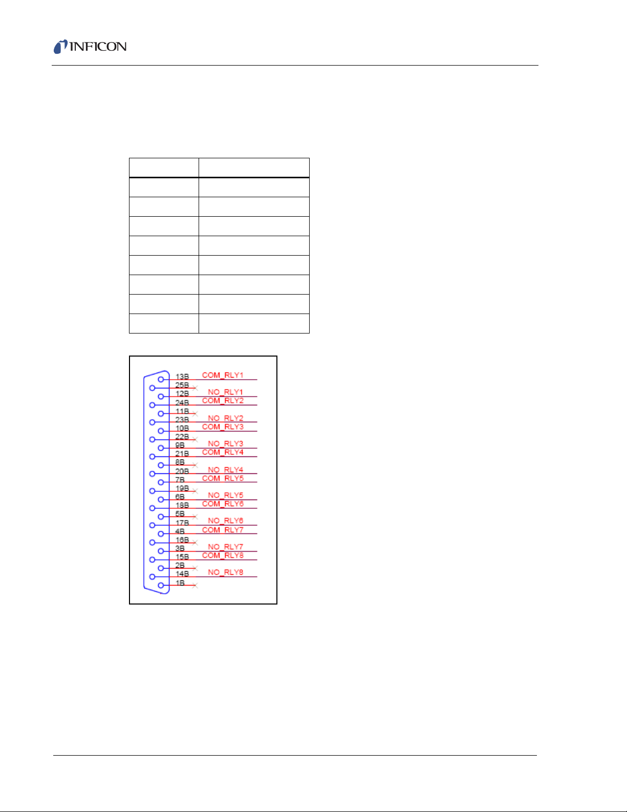
2.2.2 Relay Outputs
STM-2XM has eight normally open (NO) relay contact outputs. These outputs are
intended for low voltage (see section 1.4.4, Digital I/O, on page 1-7).
Table 2-1 Relay output contact pin numbers
Relay Contacts on pins
1 12,13
2 23,24
39,10
4 20,21
56,7
6 17,18
73,4
8 14,15
Figure 2-3 Relay output contact pin numbers
2 - 4
PN 074-614-P1A
Page 31

2.2.3 Analog Outputs
For functions associated with the analog outputs, see section 1.4.4, Digital I/O, on
page 1-7.
Table 2-2 Analog output contact pin numbers
Analog Output Connections
1 9(+), relative to pin 5 or 1
2 4(+), relative to pin 5 or 1
3 2(+), relative to pin 5 or 1
4 6(+), relative to pin 5 or 1
Figure 2-4 Analog output contact pin numbers
STM-2XM Operating Manual
PN 074-614-P1A
2 - 5
Page 32

STM-2XM Operating Manual
2.2.4 Remote Inputs
STM-2XM has eight remote digital inputs that are activated by contact closure to
ground.
For the specific functions associated with the inputs, see section 1.4.4 on page 1-7.
Table 2-3 Remote input pin numbers
Input Contact on pins
Input 1 14,13
Input 2 3,13
Input 3 17,13
Input 4 6,13
Input 5 20,13
Input 6 9,13
Input 7 23,13
Input 8 12,13
Figure 2-5 Remote input pinout
PN 074-614-P1A
2 - 6
Page 33

STM-2XM Operating Manual
Substrate
Substrate Shutter
Source
Shutter
Chamber
Oscillator
Source
Power
Supply
Sensor
Sensor
Shutter
2.3 Basic Vacuum System Components
Figure 2-6 Basic vacuum system components
PN 074-614-P1A
Substrate
The substrate is the object being coated.
Source
The source is the object that emits the evaporant. STM-2XM provides support for
two sources.
Sensor
The sensor is the component that detects the evaporant. The sensor can only
detect evaporant that accumulates on the sensor crystal. To account for differences
in evaporant between the sensor and substrate, tooling adjustments are used (see
section 7.3 on page 7-2). STM-2XM provides support for two sensors.
Source shutter (optional)
The source shutter blocks the evaporant stream from the source. With the source
shutter closed, the evaporant from the source cannot reach the substrate or the
sensors. The front panel shutter buttons and the End Thickness setpoint activate
the source shutter.
2 - 7
Page 34

STM-2XM Operating Manual
Substrate shutter (optional)
The substrate shutter blocks the evaporant stream from reaching the substrate. A
closed substrate shutter will not allow material to reach the substrate but will allow
evaporant to reach the sensor(s). With a substrate shutter installed, it is possible
to have a shutter delay, where the rate can be pre-established before exposing the
substrate to the evaporant stream. STM-2XM automatically accounts for a
substrate shutter (if programmed) and will not display thickness accumulation while
the substrate shutter is closed. The displayed rate is always "live" even if the
substrate shutter is closed.
NOTE: If STM-2XM is programmed to use a substrate shutter, it ignores changes
in substrate thickness when the substrate shutter is closed. Therefore,
program STM-2XM for a substrate shutter only if a substrate shutter
actually exists in the system.
Sensor shutter (optional)
The sensor shutter blocks the evaporant stream from the sensor. Shuttered
sensors are required for rate sampling, where the sensor monitors the source for a
portion of the deposition. Shuttered sensors are also used in multiple-sensor,
multi-layer systems to keep the sensor from being contaminated with incompatible
materials on different layers
In-Vacuum Cable
The in-vacuum cable connects the sensor to the feedthrough.
Feedthrough
A feedthrough provides isolation between vacuum and atmosphere for electrical
and cooling lines.
15.2 cm (6 in.) BNC Cable
A BNC cable provides a flexible connection from the feedthrough to the oscillator.
Oscillator
The oscillator contains the electronics to operate the quartz crystal. The length from
the oscillator to the crystal should be under 1 m (40 in.).
BNC Cable
A BNC cable connects the oscillator to STM-2XM.
Ground Wire
The ground wire is preferably a solid copper ground strap that connects the
earth-grounded vacuum system to the STM-2XM ground terminal (refer to section
2.1.2, Ground Requirements, on page 2-2).
PN 074-614-P1A
2 - 8
Page 35

2.4 Deposition System Installation
Correct
Incorrect
Correct
Incorrect
Incorrect
Obstruction
Source
2.4.1 Sensor Head Installation
Install the sensor as far as possible from the evaporation source (a minimum of
25.4 cm (10 in.)) while still being in a position to accumulate thickness at a rate
proportional to accumulation on the substrate. Figure 2-7 shows proper and
improper methods of installing sensors.
NOTE: For best process reproducibility, rigidly support the sensor so that it cannot
move during maintenance and crystal replacement.
Figure 2-7 Sensor installation guidelines
STM-2XM Operating Manual
PN 074-614-P1A
To guard against spattering, use a source shutter to shield the sensor during initial
soak periods. If the crystal is hit with a particle of molten material, it may be
damaged and stop oscillating. Even in cases when the crystal does not completely
stop oscillating, it may immediately become unstable or instability may occur
shortly after deposition begins.
Plan the installation to ensure that there are no obstructions blocking a direct path
between the sensor and the source. Install sensors in such a manner that the
center axis of the crystal is aimed directly at the source to be monitored. Verify that
the angle of the sensor location (with reference to the source) is well within the
evaporant stream. If the sensor is not perpendicular to the source, the coating on
the crystal will be tapered and diminished crystal life can result.
NOTE: In many cases installing multiple sensors to monitor one source can
improve thickness accuracy for the product. The recommendations for
multiple sensors are the same as for a single sensor installation, and the
locations chosen should be as defined above.
2 - 9
Page 36

STM-2XM Operating Manual
This page is intentionally blank.
2 - 10
PN 074-614-P1A
Page 37

3.1 Front Panel Description
Power
On / Off
System
Control
Display Data
Entry
Control
Knob
Figure 3-1 Front panel
STM-2XM Operating Manual
Chapter 3
Operation
The STM-2XM front panel is divided into two functional groups:
Buttons to the left of the display are for system control.
The control knob and buttons to the right of the display are for data entry and
programming.
An audible beep will accompany each button activation. The beeper may be
disabled if desired (see section 3.2.1.2 on page 3-10).
PN 074-614-P1A
3 - 1
Page 38

STM-2XM Operating Manual
Open for
Channel 1
Close for
Channel 1
Zero for
Sensor 1
Open for
Channel 2
or
Select
Crystal 1
(Backup
Mode)
Crystal 2
Close for
Channel 2
or
Select
(Backup
Mode)
Zero for
Sensor 2
3.1.1 System Control Buttons
NOTE: All button functions can be duplicated with remote inputs.
Figure 3-2 Button functions
3 - 2
OPEN . . . . . . . . . . . . . . . . . . . . . . . . Press OPEN to open the source/substrate
shutter. When OPEN is pressed, all setpoints
(setpoint time, setpoint thickness, and end
thickness) are cleared and the film will enter
the deposit state.
NOTE: Pressing OPEN while STM-2XM is in
the deposit state has no effect.
CLOSE. . . . . . . . . . . . . . . . . . . . . . . Press CLOSE to close the source/substrate
shutter and terminate the deposition.
STM-2XM will then enter the Ready state.
NOTE: Pressing CLOSE while STM-2XM is
in the Ready state has no effect.
PN 074-614-P1A
Page 39

ZERO . . . . . . . . . . . . . . . . . . . . . . . . Press ZERO to zero the substrate thickness.
Control Knob
When ZERO is pressed, the thickness
displayed is cleared.
NOTE: If ZERO is pressed during the
Mode-Dependent Button Functions
Sensor 2 ZERO is only used in the independent mode.
Channel 2 OPEN is used to select Crystal 1 in the backup mode.
Channel 2 CLOSE is used to select Crystal 2 in the backup mode.
3.1.2 Data Entry and Programming Buttons
Figure 3-3 Data entry and programming buttons
STM-2XM Operating Manual
deposit state, the setpoint thickness
will activate when the film thickness
on the display reaches the
programmed setpoint thickness.
PROG/ENTER . . . . . . . . . . . . . . . . . Provides access to the main menu and
subsequent menus
Saves parameters after edit
Advances to the next list item in a sub-menu
after an edit has been saved
PN 074-614-P1A
CANCEL/BACK . . . . . . . . . . . . . . . . Returns to previous menu or Runtime screen
Control Knob . . . . . . . . . . . . . . . . . Scrolls up/down menu items
Scrolls through fixed choices
Increments value-based parameters
For parameters requiring multiple numeric
placeholders (density, Z-Ratio, thickness,
time, and rate), the control knob will:
increment the selected numeric
placeholder when rotated clockwise
select the next numeric placeholder
when rotated counterclockwise
3 - 3
Page 40

STM-2XM Operating Manual
Counterclockwise
Clockwise
three clicks
two clicks
3.1.3 Changing a Parameter
There are two types of parameters, enumerated and numeric. Enumerated
parameters have a list of fixed choices. Numeric parameters allow a number to be
entered. To change a parameter,
1 Press PROG/ENTER.
2 Rotate the control knob to select Edit Active Film.
3 Press PROG/ENTER to display the Editing Film menu for the active film (see
Figure 3-4).
Figure 3-4 Editing film settings
To edit the density, for example, rotate the control knob clockwise to select
DENSITY, then press PROG/ENTER. The DENSITY numeric parameter editor will
be displayed (see Figure 3-5).
Figure 3-5 Numeric parameter editor
3 - 4
Numeric parameters are changed one digit at a time.
Each digit may only be incremented, and rolls over from 9 to 0.
To select the next digit, rotate the control knob counterclockwise.
To increment the selected digit, rotate the control knob clockwise.
When finished, press the PROG/ENTER button.
To cancel the entry, press the CANCEL/BACK button.
PN 074-614-P1A
Page 41

STM-2XM Operating Manual
WARNING
Clockwise
one click
When changing an enumerated type, rotate the control knob to the appropriate
item, and press PROG/ENTER to save the selection and return to the previous
screen (see Figure 3-6).
Figure 3-6 Enumerated entry
NOTE: The help message changes appropriately with the choice.
Pressing CANCEL/BACK will cancel the entry and set it back to the previous
setting.
Enumerated choices take effect immediately.
PN 074-614-P1A
3 - 5
Page 42

3.1.4 Runtime Screen
Deposition Rate
Substrate Thickness
or Mass
Film State
Set Point
Indicators
Real-Time Chart
Context-Based
Help
Film No.:Film Name
Upper Chart Bound
Chart Type
Lower Chart Bound
Indicates Active Sensor
Sensor Shutter Closed
Sensor Shutter Open
Crystal Life (Frequency-Based)
Deposit Phase Time
Substrate Shutter
Source Shutter
Shutter Closed
Shutter Open
STM-2XM Operating Manual
Figure 3-7 STM-2XM Runtime screen component status
3 - 6
PN 074-614-P1A
Page 43

3.2 Programming
3.2.1 Main Menu
To program STM-2XM, press PROG/ENTER. The MAIN MENU will display.
Figure 3-8 Main menu
Use the control knob to select a menu item, then press PROG/ENTER. Press
CANCEL/BACK to return to the Runtime screen.
Set Active Film . . . . . . . . . . . . . . . . 1 to 15. Sets the active film.
Edit Active Film . . . . . . . . . . . . . . . Lists programmable parameters for the
STM-2XM Operating Manual
currently active film. For a description of the
settings on the film page, see section 3.2.1.1.
System Settings . . . . . . . . . . . . . . . Displays the SYSTEM PARAMS menu. For a
description of the system settings, see
section 3.2.1.2 on page 3-10.
Status/Diagnostics . . . . . . . . . . . . . Displays STM-2XM status and diagnostics.
For example, displays the raw frequency of
the crystal, the status of the inputs and
outputs, and other useful information.
Edit Any Film . . . . . . . . . . . . . . . . . Displays a selection box that allows the
choice of the film to edit, and then displays
the settings menu for the selected film.
Setup . . . . . . . . . . . . . . . . . . . . . . . . Displays the HARDWARE SETUP menu,
where STM-2XM system hardware is
PN 074-614-P1A
programmed, including sensors, shutters,
tooling, and relays. The settings on this menu
must be accurate to allow STM-2XM to
operate properly. For example, if STM-2XM
is programmed for a substrate shutter, and
one does not exist in the system, STM-2XM
will provide false readings because it will not
count any material accumulated on the
substrate during the Ready phase. For a
description of hardware settings, see section
3.2.1.3 on page 3-12.
3 - 7
Page 44

3.2.1.1 Edit Film
All parameters are listed, but during actual operation STM-2XM will show only the
parameters that are relevant to its configuration and mode.
Name . . . . . . . . . . . . . . . . . . . . . . . . Name of the film, displayed on the monitor
Density . . . . . . . . . . . . . . . . . . . . . . Density of the film material. Used to
Z-Ratio. . . . . . . . . . . . . . . . . . . . . . . Z-Ratio of the film material. Used to
Additional Tooling . . . . . . . . . . . . . Tooling applied in addition to the tooling in
STM-2XM Operating Manual
screen.
accurately calculate thickness. The density
of common materials is found in Appendix A,
Material Table.
NOTE: Density is not used in Mass mode.
accurately calculate thickness. The Z-Ratio
of common materials is found in Appendix A,
Material Table.
the setup menu.
NOTE: This only affects the film being edited
and not all films.
Setpoint Thickness . . . . . . . . . . . . Thickness/mass at which the setpoint
thickness relay (if programmed) will close.
NOTE: Each time a film is started, the
setpoint thickness condition is
cleared, and will be activated when
the thickness of the specific film (not
necessarily the total displayed
thickness) reaches the setpoint.
End Thickness . . . . . . . . . . . . . . . . Thickness/mass at which the deposit state
automatically terminates.
NOTE: Each time a film is started, the end
thickness condition is cleared. This
will be activated when the thickness
of the specific film (not necessarily
the total displayed thickness)
reaches the setpoint.
Use Backup Xtal . . . . . . . . . . . . . . . Available in Backup Mode
PN 074-614-P1A
3 - 8
Allows the sensor to switch automatically if
the active crystal fails.
Setpoint Time . . . . . . . . . . . . . . . . . Thickness/mass at which the setpoint time
relay (if programmed) will close.
Page 45

STM-2XM Operating Manual
Deposit Rate . . . . . . . . . . . . . . . . . . Desired rate for the film. Used for the rate
deviation graph (and analog output) and to
ensure the Rate digital output is steady and
within tolerance.
Shutter Delay . . . . . . . . . . . . . . . . . Activates a shutter delay for the film. During
a shutter delay, STM-2XM will monitor the
rate from the source but will keep the
substrate shutter closed. OPEN stops shutter
delay and starts the deposit phase.
NOTE: Available only if the appropriate
shutter setup is present.
Rate Sampling . . . . . . . . . . . . . . . . When using rate sampling, the sensor
shutter opens and closes during deposit to
reduce the exposure of the crystal to the
evaporant stream during deposition. This
feature is intended to extend crystal life for
processes with stable rates.
NOTE: Available only if the appropriate
shutter setup is present.
Rate Sampling Period . . . . . . . . . . Determines how often STM-2XM samples
and holds during Rate Sampling. Rate
Sampling Period minus Rate Sampling Dwell
time yields an approximate hold time (how
long STM-2XM will keep the sensor shutter
closed).
Rate Sampling Dwell . . . . . . . . . . . Determines the amount of time STM-2XM
will keep the sensor shutter open.
Time Power Enable . . . . . . . . . . . . STM-2XM will use the last known steady rate
and continue to accumulate thickness/mass
PN 074-614-P1A
at this rate if a crystal fail occurs. This allows
films to be completed even in the event of a
crystal failure.
Xtal Life Min . . . . . . . . . . . . . . . . . . Adjustable to enter the percent life at which
the crystal will fail. This sets the minimum
acceptable crystal life before a forced failure.
Auto Fail/Force Switch Xtal . . . . . . If the sensor(s) used by this film have a life
lower than Xtal Life Min, and the Auto Fail
parameter is true, then the crystal is failed.
Used to switch to a backup sensor at a given
crystal life.
3 - 9
Page 46

STM-2XM Operating Manual
Temporal Average . . . . . . . . . . . . . Number of measurement samples to
average as the effective rate. More samples
yield a more accurate rate, however, rate and
thickness will not update as quickly at higher
sampling rates.
The effective frequency accuracy is 0.03 Hz
per measurement divided by the square root
of the number of temporal average samples.
Good Rate Tolerance(%) . . . . . . . . Set as a percentage of rate deviation. When
set for good rate, a relay will activate only
within tolerance, when the good rate
condition is true.
For example, if Good Rate Tolerance is set to
10% and the target rate is set to 10 Å/s, when
the rate is between 9 and 11 Å/s (10%), the
good rate relay would be active.
NOTE: A relay must be programmed to use
this feature.
3.2.1.2 System Settings
Operational Mode. . . . . . . . . . . . . . Sets STM-2XM mode of operation (see
Table 3-1 Modes of operation
Mode Description Notes
Simple X1 Single film, single sensor Sensor 1 active only. Analog/shutter outputs
Simple X2 Single film, single sensor Sensor 2 active only. Analog/shutter outputs
Backup Single film, dual sensors Crystal switching mode.
Averaging Single film, two sensors spatially
Alloy Two films codeposited Codeposition of two materials onto a
Independent Two films cluster deposition Allows STM-2XM to be used as two separate
averaged
section 3.3, STM-2XM Operating Modes, on
page 3-17). (See Table 3-1.)
selected by changing active source.
selected by changing active source.
PN 074-614-P1A
Used for large chambers or systems with a
moving substrate.
substrate at the same time.
instruments. Recommended for cluster tools
and research systems.
3 - 10
Page 47

STM-2XM Operating Manual
Test Mode
. . . . . . . . . . . . . . . . . . . . . Test mode provides simulated sensor
Active Source
(Active Channel)
Display Mode
Plot type
Plot time scale
. . . . . . . . . . . . . . . . . . .Displays thickness in kiloangstoms (
. . . . . . . . . . . . . . . . . . . . . . . Available in single film modes.
. . . . . . . . . . . . . . . . . .Sets the horizontal axis size. Defines the
LCD Contrast
LCD Brightness
readings.
NOTE:
If STM-2XM is reset, test mode is
turned off automatically.
. . . . . . . . . . . . . . . .For single film modes, this selects where the
analog and digital outputs and inputs are
connected (refer to
section 2.2 on page 2-3
kÅ)
).
or
mass in micrograms per square centimeter
µg/cm3)
(
.
Displays the graph on the Runtime screen as
None, Rate Deviation, Rate, or Thickness.
amount of time covered by the plot before it is
overwritten.
. . . . . . . . . . . . . . . . .Adjusts the appearance of the screen. Set the
brightness to 100%, and then adjust the
contrast until the display is easily read.
Brightness can be programmed to a desired
level.
NOTE:
The screen dims when STM-2XM is
idle.
Beep [on/off]
Comm Protocol
. . . . . . . . . . . . . . . . . . . Turns the button/control knob beeper on or off.
. . . . . . . . . . . . . . . . .Serial communications mode to STM-2XM,
Sycon 9600 (9.6 Kbps), SMDP L (9.6 Kbps),
SMDP M (38.4 Kbps), and SMDP H (115.2
PN 074-614-P1A
Kbps).
If the protocol selected is Sycon 9600,
STM-2XM performs serial communication with
Sycon protocol at 9600 baud, using RS-232
electrical levels.
If the protocol selected is SMDP, STM-2XM
performs serial communication using SMDP
protocol at 9600, 38400, or 115200 baud.
3 - 11
Page 48

STM-2XM Operating Manual
CAUTION
SMDP address
3.2.1.3 Setup Parameters
Changes in the Setup menu occur immediately. Relays
and analog outputs can activate unexpectedly during
programming.
Sensor setup . . . . . . . . . . . . . . . . . Main parameter that effects the
Table 3-2 Sensor setup parameter
Sensor Setup Available modes Rate sampling
1:Single
unshuttered
. . . . . . . . . . . . . . . . . . Serial communication mode for STM-2XM. If
the SMDP address is 16, STM-2XM uses
RS-232 electrical signaling; otherwise
STM-2XM uses RS-485 signaling.
choices/modes available (see Table 3-2
capable
Simple No No
).
Backup
capable
2:Single
shuttered
3:Dual w/single
shutter
4:Dual
unshuttered
5:Dual w/dual
shutters
Simple, Averaging, Alloy, Independent No If mode is
Simple, Averaging, Alloy, Independent Yes If mode is
Simple Yes No
Simple Yes Yes
Simple
Simple
Tooling, X1:SRC1 . . . . . . . . . . . . . . The ratio between substrate thickness using
Source 1 and Sensor 1 thickness (see
section 7.3, Determining Tooling, on page
7-2).
Tooling, X2:SRC1 . . . . . . . . . . . . . . The ratio between substrate thickness using
Source 1 and Sensor 2 thickness (see
section 7.3, Determining Tooling, on page
7-2).
NOTE: In independent chambers, set this
value to zero.
PN 074-614-P1A
3 - 12
Page 49

STM-2XM Operating Manual
Tooling, X1:SRC2 . . . . . . . . . . . . . . The ratio between substrate thickness using
Source 2 and Sensor 1 thickness (see
section 7.3, Determining Tooling, on page
7-2).
NOTE: In independent chambers. Set this
value to zero.
Tooling, X2:SRC2 . . . . . . . . . . . . . . The ratio between substrate thickness using
Source 2 and Sensor 2 thickness (see
section 7.3, Determining Tooling, on page
7-2).
Weight Ratio . . . . . . . . . . . . . . . . . . Available only in spatial averaging mode.
This parameter describes the percentage of
time the substrate is near Sensor 1. In
moving substrate systems, if the substrate
spends more time near one sensor than the
other, this needs to be accounted for in the
computations. If the substrate spends 90% of
time near Sensor 1, this parameter should be
programmed for 90%. If the substrate is
fixed, the default value is 50%.
Substrate Shutr . . . . . . . . . . . . . . . Configures the substrate shutter delay
operation (see Table 3-3).
Table 3-3 Substrate shutter setup parameters
Substrate shutter
setup
None N
CH1: Substrate3 Only for film on Channel 1
CH2: Substrate Only for film on Channel 2
PN 074-614-P1A
Shared substrate Only allows shutter delay for one film at a time
Dual substrate Allows dual shutter delay (alloy shutter delay)
Shutter Delay
Thick hold
Anal. Scl Mode . . . . . . . . . . . . . . . . Thickness, Mass
3 - 13
Page 50

STM-2XM Operating Manual
Analog Out 1 to 4 . . . . . . . . . . . . . . Determines the function of each of the
analog outputs (refer to section 2.2.3 on
page 2-5 for details on wiring analog
outputs). (See Table 3-4
Table 3-4 Analog output functions
Setting Description
None Output is disabled
Pos Fscl +10 V Fixed
Neg Fscl -10 V Fixed
Remote Output is computer set value
Ch1 Rdev 1k Rate Deviation, Channel 1, 1000 Å/s
Ch1 Rdev 10 Rate Deviation, Channel 1, 10 Å/s
Ch1 Rate 1k Rate, Channel 1, 1000 Å/s
Ch1 Rate 10 Rate, Channel 1, 10 Å/s
Ch1 Thickns Thickness Recorder, Channel 1, 999 Å
.)
Ch1 Mgthick Thickness Recorder, Channel 1, 99.9 Å
Ch2 Rdev 1k Rate Deviation, Channel 2, 1000 Å/s
Ch2 Rdev 10 Rate Deviation, Channel 2, 10 Å/s
Ch2 Rate 1k Rate, Channel 2, 1000 Å/s
Ch2 Rate 10 Rate, Channel 2, 10 Å/s
Ch2 Thickns Thickness Recorder, Channel 2, 999 Å
Ch2 Mgthick Thickness Recorder, Channel 2, 99.9 Å
PN 074-614-P1A
3 - 14
Page 51

STM-2XM Operating Manual
Relay 1 to 8 . . . . . . . . . . . . . . . . . . . Determines the function of each of the digital
(relay) outputs (refer to section 2.2.2 on page
2-4 for details on wiring digital outputs). (See
Table 3-5.)
Table 3-5 Relay functions
Setting Decription
None Relay is inactive
Forced ON Relay is always active
Remote Relay is controlled with remote communications
Ch 1 FP Keys Relay is toggled using Sensor 1 OPEN/CLOSE
buttons
Ch 2 FP Keys Relay is toggled using Sensor 2 OPEN/CLOSE
buttons
Srce 1 Shtr Relay activates Channel 1 source shutter
Srce 2 Shtr Relay activates Channel 2 source shutter
Subs 1 Shtr Relay activates Channel 1 substrate shutter
Subs 2 Shtr Relay activates Channel 2 substrate shutter
Sens 1 Shtr Relay activates Sensor 1 shutter
Sens 2 Shtr Relay activates Sensor 2 shutter
Xtal 1 Fail Relay activates when Sensor 1 fails
Xtal 2 Fail Relay activates when Sensor 2 fails
Stpt 1 Time Relay activates when Channel 1 setpoint time has
elapsed
Stpt 2 Time Relay activates when Channel 2 setpoint time has
elapsed
Stpt 1 Thik Relay activates when Channel 1 setpoint thickness
has been reached
PN 074-614-P1A
Stpt 2 Thik Relay activates when Channel 2 setpoint thickness
has been reached
Ch1 Rate OK Relay activates when Channel 1 rate is steady and
within tolerance
Ch2 Rate OK Relay activates when Channel 2 rate is steady and
within tolerance
Xtl 1 N.C. Relay is Normally Closed and opens to use Sensor
1
Xtl 2 N.C. Relay is Normally Closed and opens to use Sensor
2
3 - 15
Page 52

STM-2XM Operating Manual
Input 1.1 to 1.4
Input 2.1 to 2.4 . . . . . . . . . . . . . . . . Determines the function of each of the digital
(relay) outputs for Sensor 1 (1.X) and Sensor
2 (2.X) (refer to section 2.2.4 on page 2-6 for
details on wiring remote inputs). (See Table
3-6
.)
Table 3-6 Input functions
Setting Description
None Input is ignored
Zero Thick Zero accumulated thickness
Open Source Open source shutter and in deposit mode
Close Source Closed source shutter and in monitor mode
Select Xtal Switch active crystal
Terminal Thk Source final thickness
2 Chnl Fnltk All channels final thickness (alloy mode)
Alloy Syncup Open substrate shutter and sync start channels
(alloy mode)
3 - 16
PN 074-614-P1A
Page 53

3.3 STM-2XM Operating Modes
Source Shutter
Sensor
Chamber
Sensor Shutter
Source
Substrate Shutter
Substrate
Notice that one sensor
is off.
3.3.1 Simple
In simple mode, STM-2XM can read one sensor and can control a shutter for one
source. The deposition process is a single material per layer.
Figure 3-9 Simple mode
STM-2XM Operating Manual
PN 074-614-P1A
3 - 17
Page 54

3.3.2 Backup
Source Shutter
Source
Sensor Shutter
Dual Sensor
Chamber
Substrate Shutter
Substrate
Notice that both
sensors are on. The
arrow indicates the
active sensor
Select
Select
In backup mode, STM-2XM is a single layer, single source monitor using two
sensors; one sensor is a backup for the other sensor. If the active sensor fails,
STM-2XM automatically switches to the backup sensor. The active sensor can be
switched manually by pressing the lower OPEN and CLOSE buttons on the front
panel (refer to section 3.1.1 on page 3-2).
NOTE: The 1 and 2 on these buttons indicate which sensor will be selected (see
Figure 3-10 Backup mode
STM-2XM Operating Manual
Figure 3-10).
PN 074-614-P1A
3 - 18
Crystal 1 Crystal 2
Page 55

3.3.3 Averaging
Source
Source
Substrate
Substrate Shutter
Sensor Shutter
Sensor
Chamber
Shutter
Notice that both sensors are on
and their shutters are open.
The averaging mode is spatial averaging for two sensors. STM-2XM calculates
weighted averages of two sensors to determine the film rate and thickness. Both
sensors must be active and monitored at the same time. The effective
rate/ thickness is the average of the readings between Sensor 1 and Sensor 2.
NOTE: Averaging mode requires two operational sensors.
Figure 3-11 Averaging mode
STM-2XM Operating Manual
PN 074-614-P1A
3 - 19
Page 56

3.3.4 Alloy
Sensor Shutter
Source
Sensor
Source
Substrate
Chamber
Substrate Shutter
Source
Shutters
Total Substrate
Thickness
Film No.:Film Name
Film No.:Film Name
Deposit Rate for
Source 1
Deposit Rate for
Source 2
Ratio Indicator
(Based on
current rate)
STM-2XM Operating Manual
In alloy mode, two different materials are deposited onto the substrate at the same
time. STM-2XM associates a material with a sensor. Make sure to shield the
sensors so that each sensor monitors only one source.
In alloy mode, Sensor 1 (X1) is associated with Channel/Source 1 (top line on the
Runtime screen) and Sensor 2 (X2) is associated with Channel 2/Source 2 (bottom
line on the Runtime screen) (see Figure 3-12).
In alloy mode, STM-2XM links the source or substrate shutters together, so that the
evaporants are properly codeposited on the substrate. Each channel (or both) may
still have a shutter delay phase. In this case, when the channel(s) are programmed
with shutter delay, they both enter the deposit phase at the same time by pressing
either of the two OPEN buttons. Also, each channel may independently be
programmed for rate sampling.
In alloy mode, the setpoint thickness of each source channel is independent.
The Ratio Indicator displays the ratio as measured at the instant, not an overall
ratio.
NOTE: The chart is not available in Alloy Mode.
Figure 3-12 Alloy mode
PN 074-614-P1A
3 - 20
Page 57

3.3.5 Independent
Source Shutter
Sensor
Chamber
Sensor Shutter
Source
Substrate Shutter
Substrate
Source Shutter
Sensor
Chamber
Sensor Shutter
Source
Substratre Shutter
Substrate
Source 1 Related
Source 2 Related
In independent mode, STM-2XM acts like two separate simple monitors. The
source shutters are operated independently, and the films can be deposited
independently. The two channels are completely independent. Sensor 1 (X1) is
associated with Channel/Source 1 (top line on the screen) and Sensor 2 (X2) is
associated with Channel 2/Source 2 (bottom line on the screen)
NOTE: The chart is not available in Independent Mode. The setpoint indicators on
Figure 3-13 Independent mode
STM-2XM Operating Manual
the Runtime screen (refer to Figure 3-7 on page 3-6) are also not available
in Independent mode.
PN 074-614-P1A
3 - 21
Page 58

STM-2XM Operating Manual
CAUTION
3.4 Operation
3.4.1 No Shutter Delay
Press OPEN. STM-2XM transitions from Ready to Deposit. The setpoint time,
setpoint thickness, and end thickness indicators are cleared. When the
accumulated thickness reaches the End Thickness value for the active film (refer
to section 3.2.1.1 on page 3-8), STM-2XM automatically closes the source shutter
and transitions back to the Ready phase.
NOTE: The substrate thickness is not zeroed when the deposit phase is entered.
This allows multiple layers to be deposited and the accumulated total
substrate thickness to be displayed (also known as thickness summing).
Zero the thickness by pressing ZERO before pressing OPEN to display the
thickness of a single layer.
3.4.2 Shutter Delay
From the Ready phase, press OPEN. STM-2XM will enter the shutter delay phase
(SHUT_DLY). The substrate shutter remains closed but the source shutter
(if installed) opens. This allows for preconditioning of the source and establishing
a steady rate prior to opening the substrate shutter.
While in shutter delay the Open indicator blinks. When ready to start depositing,
press OPEN again. STM-2XM will open the substrate shutter and enter the deposit
phase.
NOTE: Setpoint time, setpoint thickness, and end thickness indicators are cleared
3.4.3 Test Mode
Test mode allows STM-2XM settings and operation to be tested without performing
an actual deposition. Setting Test mode On provides a simulated rate, to simulate
the effects of a real deposition.
In Test mode, STM-2XM simulates attached sensors, and provides a simplified way
to become familiar with the STM-2XM front panel indicators and programming.
It is possible to open or close the shutter to simulate deposition and zero readings.
It is also possible to test the Time and Thickness Setpoint relays and indicators.
at the beginning of the shutter delay phase.
PN 074-614-P1A
In Test mode, all setpoints, inputs, and outputs are active.
3 - 22
Page 59

3.4.4 Rate Sampling
STM-2XM rate sampling allows for long depositions by limiting the time the sensor
is exposed to the evaporant. STM-2XM samples rate for a period of time, then
closes the sensor shutter and assumes the rate is constant. STM-2XM
continuously opens and closes the sensor shutter according to the times
programmed. While depositing, when STM-2XM closes the sensor shutter,
STM-2XM enters a HOLD phase, and the locked-in rate blinks. STM-2XM will not
enter the HOLD phase unless the measured rate is at least 50% of the
programmed deposit rate for the film or 0.5 Å/s (whichever is greater). This
prevents STM-2XM from jumping into the HOLD phase before the rate has been
established.
3.5 Film States
FAIL TPW . . . . . . . . . . . . . . . . . . . . Crystal failed; completed time power
STM-2XM Operating Manual
(thickness was incremented at last known
rate and shutter was held open until End
Thickness was reached).
X FAIL . . . . . . . . . . . . . . . . . . . . . . . Crystal failed; film was aborted; all shutters
are closed. If the crystal recovers while in the
X FAIL phase, STM-2XM will transition to the
Ready phase.
READY. . . . . . . . . . . . . . . . . . . . . . . Sensor shutters are open, but all other
shutters are closed. Monitor is ready; press
OPEN to open source/substrate shutters.
SHUT DLY . . . . . . . . . . . . . . . . . . . . Sensor and source shutters are open but
substrate shutter is closed. This allows a rate
to be established. Pressing OPEN will
transition the film to Deposit (opening the
substrate shutter).
PN 074-614-P1A
COAST. . . . . . . . . . . . . . . . . . . . . . . Crystal failed, but STM-2XM is incrementing
thickness at the last known rate and keeping
the source/substrate shutters open. Once
the end thickness is reached, the film will
transition to the FAIL_TPW state.
DEPOSIT . . . . . . . . . . . . . . . . . . . . . All shutters are open and STM-2XM is
monitoring the evaporant onto the target.
This is the normal mode.
3 - 23
Page 60

STM-2XM Operating Manual
HOLD . . . . . . . . . . . . . . . . . . . . . . . . Sensor shutters are closed during deposit,
and STM-2XM is incrementing thickness at
the last known rate.
NOTE: STM-2XM will not enter the HOLD
phase unless the measured rate is at
least 50% of the programmed
deposit rate for the film or 0.5 Å/s.
STM-2XM uses the greater of the
two values.
STABILIZ . . . . . . . . . . . . . . . . . . . . . After being in the HOLD phase, the sensor
shutter(s) are opened and STM-2XM waits
until the reading stabilizes before
accumulating the measured rate.
3 - 24
PN 074-614-P1A
Page 61

4.1 Introduction
STM-2XM is capable of RS-232 and RS-485 serial communication. To connect
STM-2XM to a computer via RS-232, use the serial cable included in the ship kit,
PN 783-506-000-P1.
STM-2XM can be programmed offline and the offline settings can be saved.
STM-2XM supports Sycon protocol for backwards compatibility, SMDP protocol for
faster communication, and multiple instruments on the same RS-485 link (see
Chapter 5, Communications).
To use INFICON STM-2XM FilmMaker software, first install the Protocol Server
(see section 4.2.1). Then install the INFICON STM-2XM FilmMaker software (see
section 4.2.2).
STM-2XM Operating Manual
Chapter 4
Software
4.2 Installing INFICON STM-2XM FilmMaker Software
INFICON STM-2XM FilmMaker Software supports one STM-2XM.
4.2.1 Installing the Protocol Server
1 Insert the Thin Film Manuals CD into the CD drive of the computer that will be
connected to STM-2XM.
2 Click Windows Explorer or File Explorer >> Computer >> (CD drive letter:)
>> Common Software.
3 Double click setup_smdp_svr_lv.exe. The Zip Self-Extractor window will
display.
PN 074-614-P1A
4 Click Unzip. The SMDP Serial Protocol Server window will display.
5 On the Destination Directory pane, click Browse to select the location all
software will be installed.
6 Click Next.
7 Read the license agreement.
8 Click I accept License Agreement(s).
9 Click Next.
10 Review the summary of information.
11 Click Next. Installation Complete will display.
4 - 1
Page 62

STM-2XM Operating Manual
12 Click Next. The Setup Wizard pane will display.
13 Click Next. The Confirm Installation pane will display.
14 Click Next.
15 Read the license agreement.
16 Click I Agree.
17 Click Next. Installation Complete will display.
18 Click Close.
19 Click Close on the Zip Self-Extractor.
4.2.2 Installing INFICON STM-2XM FilmMaker Software
1 Insert the Thin Film Manuals CD into the CD drive of the computer that will be
connected to STM-2XM.
2 Click Windows Explorer or File Explorer >> Computer >> (CD drive letter:)
>> STM-2XM >> TOOLS >> FilmMaker.
3 Double click setup_INFICON_2xm_filmmaker.exe. The Zip Self-Extractor
window will display.
4 Click Unzip. The INFICON 2XM FilmMaker window will display.
5 On the Destination Directory pane, click Browse to select the location all
software will be installed.
6 Click Next.
7 Review the summary of information.
8 Click Next. Installation Complete will display.
9 Click Finish.
PN 074-614-P1A
4 - 2
Page 63

STM-2XM Operating Manual
4.2.3 Starting INFICON STM-2XM FilmMaker Software
4.2.3.1 Starting the Software in Windows XP or Windows 7
1 Click Start >> All Programs >> INFICON >> INFICON STM-2XM FilmMaker.
2 The STM-2XM-ParmManager.vi window will display (see Figure 4-1).
Figure 4-1 STM-2XM-ParmManager.vi initial display
PN 074-614-P1A
4.2.3.2 Starting the Software in Windows 8
1 In the Start window, click the STM-2XM FilmMaker icon.
2 If the icon cannot be found:
2a Click Search >> Apps.
2b Type STM in the Search text box.
2c Click the INFICON STM-2XM FilmMaker icon.
4 - 3
Page 64

STM-2XM Operating Manual
4.3 STM-2XM Parameter Manager
Figure 4-2 STM-2XM-ParmManager.vi
4 - 4
Main tab (see section 4.3.1)
PN 074-614-P1A
Films tab (see section 4.3.2 on page 4-8)
System tab (see section 4.3.3 on page 4-10)
Save/Load file tab (see section 4.3.4 on page 4-17)
Save/Load instrument tab (see section 4.3.5 on page 4-18)
About tab (see section 4.3.6 on page 4-20)
Page 65

4.3.1 Main Tab
Communication and utilities are accessed on the Main tab. (Refer to Figure 4-2.)
NOTE: Right-clicking on a value or parameter and then clicking Description and
Tip will display additional information about that value or parameter.
4.3.1.1 Main Setup Pane
Communication Settings
Com Port# . . . . . . . . . . . . . . . . . . . . 1 to 255
Protocol. . . . . . . . . . . . . . . . . . . . . . Sycon @ 9.6 Kbps, SMDP L (9.6 Kbps),
STM-2XM Operating Manual
Sets the communications port that STM-2XM
is communicating through.
SMDP M (38.4 Kbps), SMDP H (115.2 Kbps).
Adjustable baud rate.
NOTE: This value must match the Comm
Protocol setting in the System
Settings menu on STM-2XM (refer to
section 3.2.1.2 on page 3-10).
Slave Address. . . . . . . . . . . . . . . . . 16 to 255
SMDP address the software will use for serial
communication with STM-2XM.
NOTE: This value must match the SMDP
Address setting in the System
Settings menu on STM-2XM (refer to
section 3.2.1.2 on page 3-10).
Timeout(ms) . . . . . . . . . . . . . . . . . . 150 to 20000
The amount of time in microseconds that the
PN 074-614-P1A
software will wait for a response before
issuing an error.
Program Control
Exit Program . . . . . . . . . . . . . . . . . . Click to safely stop communications and exit
the software program.
Purge/Re-Init all edit controls . . . . Returns all parameters edited using the
software to default values.
4 - 5
Page 66

STM-2XM Operating Manual
Instrument Communication Status
Instrument Online? . . . . . . . . . . . . Indicator to display communication status.
With established communication, the
indicator will illuminate a light green color.
Without established communication, the
indicator will illuminate a dark green color
(see Figure 4-3).
Figure 4-3 Instrument online indicator
Firmware Version . . . . . . . . . . . . . . Displays the firmware version of the
connected STM-2XM.
Comm Status:. . . . . . . . . . . . . . . . . Displays communications error messages. If
communications have been established
without error, OK: [CMD:@] will be displayed.
Num Instances . . . . . . . . . . . . . . . . Shows number of instruments using the
communication server. It is possible to have
multiple instances of STM-2XM Parm
Manager.vi running.
SMDP_SVR Build . . . . . . . . . . . . . . Build or version of the communication server.
PN 074-614-P1A
4 - 6
Page 67

4.3.1.2 Utilities Pane
Arbitrary file send
Send File to instrument . . . . . . . . . Selects a parameter file (*.2XM) to send to
File Dnld Status . . . . . . . . . . . . . . . Displays status of file download to
Arbitrary communication
Send CMD to instrument . . . . . . . . Click to send remote command.
CMD to send . . . . . . . . . . . . . . . . . . Enter command in the CMD to send box.
Response . . . . . . . . . . . . . . . . . . . . Receives the reply from the command sent.
Status. . . . . . . . . . . . . . . . . . . . . . . . Displays communications error messages. If
STM-2XM Operating Manual
STM-2XM.
STM-2XM. Error messages and comments
will be displayed after a file is selected for
transmission.
(See section 5.8, Communications
Commands, on page 5-17.)
communications have been established
without error, OK: [CMD:@] will be
displayed.
PN 074-614-P1A
4 - 7
Page 68

STM-2XM Operating Manual
4.3.2 Films Tab
Figure 4-4 Films tab
4 - 8
NOTE: Right-clicking on a value or parameter and then clicking Description and
Tip will display additional information about that value or parameter.
Copy and paste controls for current edit film pane
Copy film. . . . . . . . . . . . . . . . . . . . . Click to copy the current film number
displayed and place it on the clipboard.
film on clipboard . . . . . . . . . . . . . . Displays the film that has been copied and is
in queue.
PN 074-614-P1A
Page 69

STM-2XM Operating Manual
Paste film . . . . . . . . . . . . . . . . . . . . Click to paste the film parameters for the
displayed film in the film on clipboard box
onto the current film parameters displayed,
thereby replacing the values for the current
film.
All films pane
Use the spin box to increment or decrement the values for each of the parameters
listed below.
EDITING film# . . . . . . . . . . . . . . . . . 1 to 15
Name . . . . . . . . . . . . . . . . . . . . . . . . 8 character maximum
Density . . . . . . . . . . . . . . . . . . . . . . 0.40 to 99.99 g/cm
3
Z-Ratio . . . . . . . . . . . . . . . . . . . . . . . 0.100 to 9.999
Tooling. . . . . . . . . . . . . . . . . . . . . . . 10 to 999.9%
Setpoint mass. . . . . . . . . . . . . . . . . 0.00 to 9999.99 µg/cm²
Setpoint Thickness . . . . . . . . . . . . 0.000 to 999.999 kÅ
End mass . . . . . . . . . . . . . . . . . . . . 0.00 to 9999.99 µg/cm²
End Thickness . . . . . . . . . . . . . . . . 0.000 to 999.999 kÅ
Use Backup. . . . . . . . . . . . . . . . . . . Select to enable the use of the backup crystal
(refer to section 3.2.1.1 on page 3-8).
Setpoint Time . . . . . . . . . . . . . . . . . 00:00:00 to 9:59:59 h:mm:ss
Desired Rate . . . . . . . . . . . . . . . . . . 0.00 to 99.99 µg•s/cm²
Desired Rate . . . . . . . . . . . . . . . . . . 0.0 to 999.9 Å/s
Do shutter delay? . . . . . . . . . . . . . . Select to enable shutter delay (refer to
section 3.2.1.1 on page 3-8).
Do rate sampling . . . . . . . . . . . . . . Select to enable rate sampling (refer to
section 3.2.1.1 on page 3-8).
PN 074-614-P1A
Sampling interval . . . . . . . . . . . . . . 00:00:00 to 9:59:59 h:mm:ss
Sampling Dwell. . . . . . . . . . . . . . . . 00:00:00 to 9:59:59 h:mm:ss
Do time/power. . . . . . . . . . . . . . . . . Select to enable time/power upon crystal fail
(refer to section 3.2.1.1 on page 3-8).
Xtal min life . . . . . . . . . . . . . . . . . . . 0 to 99%
Force fail on min life . . . . . . . . . . . Select to enable an automatic crystal fail
upon reaching the minimum crystal life input
(refer to section 3.2.1.1 on page 3-8).
# Samples . . . . . . . . . . . . . . . . . . . . 1 to 50
Good Rate Tolerance . . . . . . . . . . . 0 to 50%
4 - 9
Page 70

STM-2XM Operating Manual
4.3.3 System Tab
Use the spin box to select parameter values (see Figure 4-5).
Figure 4-5 System tab
4 - 10
PN 074-614-P1A
NOTE: Right-clicking on a value or parameter and then clicking Description and
Tip will display additional information about that value or parameter.
Page 71

4.3.3.1 Setup parameters Pane
Sensor setup. . . . . . . . . . . . . . . . . . Main parameter that affects the
STM-2XM Operating Manual
choices/modes available (see Table 4-1
Table 4-1 Sensor setup parameter
).
Sensor Setup Available modes Rate sampling
capable
1:Single
unshuttered
2:Single shuttered Simple Yes No
3:Dual w/single
shutter
4:Dual unshuttered Simple, Averaging,
5:Dual w/dual
shutters
Simple No No
Simple Yes Yes
No If mode is
Alloy, Independent
Simple, Averaging,
Alloy, Independent
Yes If mode is
Backup
capable
Simple
Simple
Substrate shutter setup . . . . . . . . . The parameter that describes the shutter
assembly of the substrate(s) (see Table 4-2).
Table 4-2 Substrate shutter setup parameters
Substrate shutter
setup
None N
CH1: Substrate Only for film on Channel 1
Shutter Delay
Thick hold
CH2: Substrate Only for film on Channel 2
Shared substrate Only allows shutter delay for
one film at a time
Dual substrate Allows dual shutter delay
(alloy shutter delay)
PN 074-614-P1A
Tooling and Weights
Tooling X1:S1 . . . . . . . . . . . . . . . . . The ratio between substrate thickness using
Source 1 and Sensor 1 thickness (see
section 7.3, Determining Tooling, on page
7-2).
Tooling X2: S1 . . . . . . . . . . . . . . . . The ratio between substrate thickness using
Source 1 and Sensor 2 thickness (see
section 7.3, Determining Tooling, on page
7-2).
NOTE: For independent chambers, set this
value to zero.
4 - 11
Page 72

STM-2XM Operating Manual
Tooling X1:S2 . . . . . . . . . . . . . . . . . The ratio between substrate thickness using
Source 2 and Sensor 1 thickness (see
section 7.3, Determining Tooling, on page
7-2).
NOTE: For independent chambers, set this
value to zero.
Tooling X2:S2 . . . . . . . . . . . . . . . . . The ratio between substrate thickness using
Source 2 and Sensor 2 thickness (see
section 7.3, Determining Tooling, on page
7-2).
Weight Ratio . . . . . . . . . . . . . . . . . . Available only in spatial averaging mode.
This parameter describes the percentage of
time the substrate is near Sensor 1. In
moving substrate systems, if the substrate
spends more time near one sensor than the
other, this needs to be accounted for in the
computations. If the substrate spends 90% of
time near Sensor 1, this parameter should be
programmed for 90%. If the substrate is
fixed, the default value is 50%.
Analog outputs
Analog output mode . . . . . . . . . . . 0: Thickness, 1: Mass
PN 074-614-P1A
4 - 12
Page 73

STM-2XM Operating Manual
Analog output 1 to 4 function . . . . Determines the function of each of the
analog outputs (refer to section 2.2.3 on
page 2-5 for details on wiring analog
outputs). (See Table 4-3.)
Table 4-3 Analog output functions
Setting Description
0: Zero volts Output is disabled
1: +10 V Fixed +10 V Fixed
2: -10 V Fixed -10 V Fixed
3: Computer controlled Output is computer set value
4: Rate Deviation, Channel 1, 1000 Å/S Rate Deviation, Channel 1, 1000 Å/s
5: Rate Deviation, Channel 1, 10 Å/S Rate Deviation, Channel 1, 10 Å/s
6: Rate, Channel 1, 1000 Å/S Rate, Channel 1, 1000 Å/s
7: Rate, Channel 1, 10 Å/S Rate, Channel 1, 10 Å/s
8: Thickness, Channel 1, 999 Å Thickness Recorder, Channel 1, 999 Å
9: Thickness, Channel 1, 99.9 Å Thickness Recorder, Channel 1, 99.9 Å
10: Rate Deviation, Channel 2, 1000 Å/S Rate Deviation, Channel 2, 1000 Å/s
11: Rate Deviation, Channel 2, 10 Å/S Rate Deviation, Channel 2, 10 Å/s
12: Rate, Channel 2, 1000 Å/S Rate, Channel 2, 1000 Å/s
13: Rate, Channel 2, 10 Å/S Rate, Channel 2, 10 Å/s
14: Thickness, Channel 2, 999 Å Thickness Recorder, Channel 2, 999 Å
15: Thickness, Channel 2, 99.9 Å Thickness Recorder, Channel 2, 99.9 Å
PN 074-614-P1A
4 - 13
Page 74

STM-2XM Operating Manual
Digital (relay) outputs
Relay 1 to 8 function . . . . . . . . . . . Determines the function of each of the digital
(relay) outputs (refer to section 2.2.2 on page
2-4 for details on wiring digital outputs). (See
Table 4-4.)
Table 4-4 Relay functions
Setting Decription
0: Forced OFF Relay is inactive
1: Forced ON Relay is always active
2: Computer controlled Relay is controlled with remote communications
3: Front panel buttons, top Relay is toggled using Sensor 1 OPEN/CLOSE buttons
4: Front panel buttons, bottom Relay is toggled using Sensor 2 OPEN/CLOSE buttons
5: Channel 1 source shutter Relay activates Channel 1 source shutter
6: Channel 2 source shutter Relay activates Channel 2 source shutter
7: Channel 1 substrate shutter Relay activates Channel 1 substrate shutter
8: Channel 2 substrate shutter Relay activates Channel 2 substrate shutter
9: Sensor 1 (X1) active Relay activates Sensor 1 shutter
10: Sensor 2 (X2) active Relay activates Sensor 2 shutter
11: Sensor 1 (X1) failed Relay activates when Sensor 1 fails
12: Sensor 2 (X2) failed Relay activates when Sensor 2 fails
13: Channel 1 setpoint time Relay activates when Channel 1 setpoint time has elapsed
14: Channel 2 setpoint time Relay activates when Channel 2 setpoint time has elapsed
15: Channel 1 setpoint thick Relay activates when Channel 1 setpoint thickness has been
reached
16: Channel 2 setpoint thick Relay activates when Channel 2 setpoint thickness has been
reached
17: Channel 1 good rate Relay activates when Channel 1 rate is steady and within tolerance
18: Channel 2 good rate Relay activates when Channel 2 rate is steady and within tolerance
19: Complement of #9 Relay is Normally Closed and opens to use Sensor 1
20: Complement of #10 Relay is Normally Closed and opens to use Sensor 2
PN 074-614-P1A
4 - 14
Page 75

STM-2XM Operating Manual
Digital inputs
CH1/CH2 input 1 to 4 function. . . . Determines the function of each of the digital
(relay) outputs (refer to section 2.2.4 on page
2-6 for details on wiring remote inputs). (See
Table 4-5.)
Table 4-5 Input functions
Setting Description
0: Input disabled Input is ignored
1: Thickness zero Zero accumulated thickness
2: Open as if from front panel Open source shutter and in deposit mode
3: Close as if from front panel Closed source shutter and in monitor mode
4: Select Sensor 1/ Sensor 2 (backup mode) Switch active crystal
5: Trigger final thickness Source final thickness
6: Trigger final thicknesses (alloy mode) All channels final thickness (alloy mode)
7: Sync start channels (alloy mode) Open substrate shutter and sync start
channels (alloy mode)
PN 074-614-P1A
4 - 15
Page 76

STM-2XM Operating Manual
4.3.3.2 System parameters Pane
Main system settings
System Mode . . . . . . . . . . . . . . . . . Sets STM-2XM to operate in a certain mode
Mode Action Mode Action
Test Mode . . . . . . . . . . . . . . . . . . . . Select to enable Test mode where sensor
Active Channel/Source . . . . . . . . . CH1, CH2
(refer to section 3.3 on page 3-17). (See
Table 4-6.
0 Simple, Sensor X1 active 3 Averaging
1 Simple, Sensor X2 active 4 Alloying
2 Sensor backup 5 Independent
)
Table 4-6 System mode
readings are simulated.
NOTE: If STM-2XM is reset, test mode is
turned off automatically.
Selects where the analog and digital outputs
and inputs are connected.
Display Mode . . . . . . . . . . . . . . . . . Displays thickness in kiloangstroms (kÅ) or
mass in
µg/cm3).
(
micrograms per square centimeter
Chart settings
Plot type . . . . . . . . . . . . . . . . . . . . . Available in single film modes.
Displays the graph on the Runtime screen as
No plot, Rate Deviation, Rate, or
Thickness/Mass.
Plot time scale . . . . . . . . . . . . . . . . Sets the horizontal axis size. Defines the
amount of time covered by the plot before it
is overwritten.
Screen + sound
LCD Contrast . . . . . . . . . . . . . . . . . 10 to 85
Adjusts the appearance of the screen.
LCD Brightness . . . . . . . . . . . . . . . 1 to 99
Adjusts the appearance of the screen.
PN 074-614-P1A
4 - 16
Beeper on? . . . . . . . . . . . . . . . . . . . Select to enable a sound when a front panel
button is pressed.
Page 77

4.3.4 Save/Load file Tab
Save a parameter file as *.2XM or load a parameter file from this tab (see Figure
4-6).
Figure 4-6 Save/Load file tab
STM-2XM Operating Manual
PN 074-614-P1A
NOTE: Right-clicking on a value or parameter and clicking Description and Tip
will display more information about that value or parameter.
Film Selection Control . . . . . . . . . . A comma separated list of pages or ranges to
Save/Load. Type "all" to Save/Load all pages
or ranges of parameters.
Setup/System Params . . . . . . . . . . Select to enable to Save/Load setup and
system parameters in addition to film
parameters.
4 - 17
Page 78

STM-2XM Operating Manual
Open . . . . . . . . . . . . . . . . . . . . . . . . Click to browse and select the location of a
Save. . . . . . . . . . . . . . . . . . . . . . . . . Click to browse and select the location to
Message . . . . . . . . . . . . . . . . . . . . . Displays error messages or comments
4.3.5 Save/Load instrument Tab
This tab is used to upload a configuration file from STM-2XM into the STM-2XM
software. It will also download the configuration to STM-2XM (see Figure 4-7).
Figure 4-7 Save/Load instrument tab
file to open.
save the current process and system
configuration.
regarding the saving or loading of process
and system configuration files.
4 - 18
PN 074-614-P1A
Page 79

STM-2XM Operating Manual
NOTE: Right-clicking on a value or parameter and then clicking Description and
Tip will display additional information about that value or parameter.
Film Selection Control . . . . . . . . . . A comma separated list of pages or ranges to
Save/Load. Type "all" to Save/Load all pages
or ranges of parameters.
Setup/System Params . . . . . . . . . . Select to enable to Save/Load setup and
system parameters in addition to film
parameters.
Read from 2XM . . . . . . . . . . . . . . . . Click to upload a configuration file from
STM-2XM into the software.
Write to 2XM . . . . . . . . . . . . . . . . . . Click to download the configuration
parameters from the software and into
STM-2XM.
Message . . . . . . . . . . . . . . . . . . . . . Displays error messages or comments
regarding the saving or loading of process
and system configuration files.
PN 074-614-P1A
4 - 19
Page 80

STM-2XM Operating Manual
4.3.6 About Tab
Displays copyright, version history, and software version number (see Figure 4-8).
Figure 4-8 About tab
4 - 20
PN 074-614-P1A
Page 81

5.1 Introduction
123456
RS-232/485
TAB
Chapter 5 describes the Sycon Protocol and the Sycon Multi Drop Protocol
(SMDP).
5.2 Communications Connections
STM-2XM interfaces to a computer using RS-232 through the SMDP cable
provided in the ship kit, PN 783-506-000-P1.
5.2.1 RS-232/RS-485 Connector
STM-2XM uses RS-232 and RS-485 for serial communications. Both
communication ports are accessed through the RS-232/485 connector. The
RS-232/485 connector location and pin numbering is shown in Figure 5-1.
STM-2XM Operating Manual
Chapter 5
Communications
Figure 5-1 Rear panel
PN 074-614-P1A
5 - 1
Page 82

STM-2XM Operating Manual
5.2.2 RS-232 Point-to-Point Mode
STM-2XM can be set to RS-232 point-to-point mode for a single host-slave
connection by selecting SMDP address 16 (0x10). Point-to-point mode can be set
to one of three baud rates (high-115200, medium-38400, low-9600) via the Comm
Protocol menu accessed from the System Settings menu (refer to section 3.2.1.2
on page 3-10). This supports a three wire (transmit, receive, common ground)
interface that can be directly connected to most RS-232 ports of a computer or
controller. The protocol is standard 10 bit (1 start bit, 8 data bits, 1 stop bit) (see
section 5.5 on page 5-4).
5.2.3 RS-485 TTL Differential Signaling Mode
RS-485 TTL differential signaling mode is selected by SMDP address values 17
through 254. In TTL differential signaling mode, two wires are time-shared
(half-duplex) between a master and 1 to N slaves. Slaves monitor the state of the
A/B differential signals, looking for the master to a frame
(start-data-stop-start-data-stop-etc). When a slave receives a frame that is
addressed for it (address byte value 17 to 254), the slave will drive the A/B wire pair
differentially with its own reply frame, which the master (and all other slaves) will
see. Since the reply has an address byte embedded in it, other slaves will ignore
the reply. The host will decode and verify (via checksum) the reply. If acceptable,
the reply will be used by the master.
The RS-232 pin assignments for the PN 783-506-000 cable (see Figure 5-2) are
Pin 2 (TXD), Pin 3 (RXD), and Pin 5 (Signal GND). The cable wiring is
straight-through (not null modem).
When using the PN 783-560-000 cable for RS-485 communication, the pin
assignments are Pin 2 - Green (inverting signal), Pin 3 - Red (non-inverting signal),
and Pin 5 (Signal GND). The RS-485 / TIA-485 standard does not specify pin
assignments, so a modification may be needed at the cable end connected to the
RS-485 card. Refer to the RS-485 card operating manual to determine which pins
are inverting and non-inverting.
NOTE: If the inverting and non-inverting signal connections to the RS-485 card are
reversed, the RS-485 link will not communicate; however, STM-2XM and
the RS-485 card will not be damaged.
PN 074-614-P1A
5 - 2
Page 83

STM-2XM Operating Manual
PIN 2 - GREEN (RS-232 TXD) [RS-485 Inverting Signal]
PIN 3 - RED (RS-232 RXD) [RS-485 Non-inverting Signal]
PIN 5 - ORANGE (Signal GND) [Signal GND]
PN 783-506-000
RS-232 Cable
Figure 5-2 PN 783-506-000 cable for RS-485
The RS-485 communications interface must be wired properly with the same baud
rate used for all instruments and a unique SMDP address used for each connected
instrument for communication to occur. A message will not be acknowledged, and
the software will timeout if any of these conditions are not met.
5.3 Electrical
The STM-2XM SMDP interface is two-wire RS-485 providing a single master,
multi-slave, half-duplex network. STM-2XM can also implement this protocol over
an RS-232 interface. This allows STM-2XM to be used for RS-232 or RS-485
networks and makes an upgrade path from point-to-point.
In point-to-point RS-232 mode, the transmit and receive data lines are converted
to logic levels with a standard RS-232 transceiver.
In RS-485 bus mode, a two-wire bus uses lines designated as inverting and
non-inverting and carries complementary Transistor-Transistor Logic (TTL) level
differential signals, time-shared (half-duplex) for messages to and from the master.
When the line is idle, the non-inverting signal line is at a TTL high.
PN 074-614-P1A
5 - 3
Page 84

STM-2XM Operating Manual
5.3.1 RS-485 Line Signal
The first bit, a start bit, is a data zero value, with the non-inverting signal line going
to a logic low (<1 volt). The opposite differential signal (inverting RS-485) goes to
a logic high (>2 volts) during the same start bit time.
NOTE: After the start bit, the eight data bits are presented in order from least
significant bit (D0) through most significant bit (D7), and then followed with
a stop bit (logic 1 value).
The values of the ASCII code bits as 1 or 0 are represented as normal logic
(1 is high TTL, 0 is low TTL) on the non-inverting RS-485 line.
For example, the opening protocol character STX (ASCII 0x02) is transmitted on
the non-inverting RS-485 wire START0-0-1-0-0-0-0-0-0-STOP1. This can be
examined on an oscilloscope.
5.3.2 Bit Time
At 115200 baud, for example, a bit time is 8.68 microseconds (s). The start and
LSB zero values together would hold the line low for 2*8.68
the D1 bit value of one would take the line high for 8.68
s or 17.36 s. Then
s.
The remainder of the frame data bits are a zero value, until the final stop bit one
value returns the line to the Idle / 1 / Marking state. At the end of the master
transmission, the line driver for the master enters a high-impedance, inactive state,
so that the slave can reply over the same two wires by sending back a similarly
encoded frame. This master/slave, command/reply interaction is at the heart of the
protocol.
5.4 Bauds
Sycon Protocol must be 9600 baud.
All STM-2XM on the same network must have the same baud rate.
5.5 Message Format
5.5.1 Sycon Protocol
The general format for sending and receiving commands using Sycon Protocol with
STM-2XM uses a start character, a length, data, and a checksum.
NOTE: Each field in angle brackets (< >) is a byte, and is not optional. Fields in
regular brackets ([ ]) are optional. Ellipses (...) mean one or more of the
previous.
PN 074-614-P1A
5 - 4
Page 85

5.5.1.1 Command Format
<STX><DATA LENGTH><DATA>...<CKSUM>
STX . . . . . . . . . . . . . . . . . . . . . . . . . Start of text character (hexadecimal 02).
DATA LENGTH . . . . . . . . . . . . . . . . ASCII character from SOH (1 decimal)
STM-2XM Operating Manual
If a different character is received, it is
discarded.
through P (80 decimal) and indicates the
number of data characters in the message.
The data length is the count of message
bytes following the data length byte plus one
to designate the checksum termination. The
count of message bytes can be any valid 8 bit
decimal, from 0 (hexadecimal 00) through
255 (hexadecimal FF).
STM-2XM uses this number to determine
where the end of the command is. If a
mismatch between this number and the
actual number of data characters in the
message occurs, one of the following will
ensue:
If the data length number is low,
STM-2XM will terminate the command
prematurely. The checksum will not
match. It will not respond in any way.
If the data length number is high,
STM-2XM will be waiting for more
characters than actually contained in the
message.
NOTE: In order to recover from either error,
PN 074-614-P1A
the host computer must have a
time-out/retry capability built into the
software. There is a maximum of 80
data characters allowed in any
communications message, although
most messages are short. The
length of commands and replies
depend on command specifics. This
does not include any packet
formatting characters.
5 - 5
Page 86

STM-2XM Operating Manual
DATA . . . . . . . . . . . . . . . . . . . . . . . . 1 to 80 characters of data (see section 5.8 on
CKSUM . . . . . . . . . . . . . . . . . . . . . . Checksum character for the message
5.5.2 Sycon Multi-Drop Protocol (SMDP)
SMDP is a byte-packet, binary protocol. All eight bits of the data of a byte/character
are used. Standard asynchronous serial conventions apply. The link must be
configured for one start bit, eight data bits, and one or more stop bits. The logic
polarity and bit order adopt the standard used for asynchronous serial
communications (refer to section 5.3.1). A packet begins with STX (ASCII 0x02)
and ends with CR (carriage return, 0x0D).
page 5-17 for data commands).
NOTE: STX characters are not allowed in
the data field.
This is the modulo-256 checksum of data
bytes only. The checksum can be any valid 8
bit decimal, from 0 (hexadecimal 00) through
255 (hexadecimal FF) depending on the data
field contents. If this does not match the
actual checksum of the data. STM-2XM will
not respond to the command.
The SMDP specification provides several common, mandated command codes.
STM-2XM responds to these common messages. For example, the reset
command will cause STM-2XM to reboot, as though power was cycled. This will set
STM-2XM into a known state. Another common command queries the product type
or ID. This command (0x30) will return an ASCII integer code that identifies the
product type (see section 5.5.2.1.2 on page 5-10). This allows a master computer
to poll a network and locate devices by their types and ensure that the proper
connection and commands are used for the appropriate product.
NOTE: Each field in angle brackets (< >) is a byte, and is not optional. Fields in
regular brackets ([ ]) are optional. Ellipses (...) mean one or more of the
previous.
5.5.2.1 Command Format
<STX><ADDR><CMD_RSP>[<DATA>...]<CKSUM1><CKSUM2><CR>
STX . . . . . . . . . . . . . . . . . . . . . . . . . Start of text character (hexadecimal 02)
PN 074-614-P1A
Multiple STX characters in a row are allowed.
Data between STX characters is ignored. A
single STX character initializes the receiver
to receive a new message, purging any data
collected since the last STX character or
carriage return received.
5 - 6
Page 87

STM-2XM Operating Manual
ADDR . . . . . . . . . . . . . . . . . . . . . . . . One byte address field
The address (ADDR) byte identifies the
SMDP address (refer to section 3.2.1.2 on
page 3-10) in order to select which device the
command/query is sent to.
NOTE: RS-485 communication limits the
number of attached devices to 32.
Each connected instrument must be
assigned a unique address. The
slave reply repeats the address
when it replies to the master,
verifying the address of the
instrument receiving the command.
The range of values are 10 hexadecimal to
FE hexadecimal (16 to 254 decimal).
Address FF hexadecimal is reserved. It is
used as an extension to indicate another byte
of address information follows for products
that have an address range higher than an
address of FE hexadecimal.
CMD_RSP . . . . . . . . . . . . . . . . . . . . Command/Response field
When a command is sent from master to
slave, the RSPF bit is zero and the RSP field
(3 bits) is zero.
When a command is received from a slave to
a master, CMD bits are the same as in the
message that was sent (see section
5.5.2.1.2), but the RSP2 through RSP0 field
will be non-zero (indicating actual unit
response status) (see section 5.5.2.1.3). The
PN 074-614-P1A
slave will set or clear the RSPF flag bit in the
reply CMD_RSP frame to indicate an
unacknowledged slave reset. This bit only
has meaning when a command is going from
slave to master. If this bit is 1, the slave has
been reset since the last AckPF,
acknowledge power fail, flag command was
received (see Table 5-1).
Table 5-1 Command/Response
D7 D6 D5 D4 D3 D2 D1 D0
CMD3 CMD2 CMD1 CMD0 RSPF RSP2 RSP1 RSP0
5 - 7
Page 88

STM-2XM Operating Manual
DATA . . . . . . . . . . . . . . . . . . . . . . . . Optional data
STX and carriage return characters are not
allowed in the data field.
To send a data byte valued as hexadecimal
02, send the protocol escape character
(hexadecimal 07) followed by zero
(hexadecimal 30).
To send a data byte valued at hexadecimal
0D, send the protocol escape character
(hexadecimal 07) followed by one
(hexadecimal 31).
To send a data value of hexadecimal 07,
send the protocol escape character followed
by two (hexadecimal 32).
The protocol escape character cannot be
sent as a single byte, but can only be sent as
the first byte of a pair, followed by an ASCII
0, 1, or 2.
If the protocol escape character is seen but is
not followed by an ASCII 0, 1, or 2, the
command is invalid and is ignored.
CKSUM1,2 . . . . . . . . . . . . . . . . . . . . Checksum characters for the message
This is the mod-256 checksum of the
command binary message data. The
checksum does not include STX and
carriage return, and it is calculated before
escape character byte stuffing (see section
5.5.2.1.1).
PN 074-614-P1A
5 - 8
Page 89

5.5.2.1.1 Checksum
CAUTION
Compute the mod 256 checksum of ADDR, CMD_RSP and DATA fields, before
byte stuffing with escape characters. This is the logical content (payload) of the
command.
CKSUM1 is the upper (most significant) four bits of the checksum (read as a
nibble, 0 through 15, or right justified) plus hexadecimal 30 (ASCII zero). This
yields an ASCII character from zero (hexadecimal 30) to ? (hexadecimal 3f).
CKSUM2 is the lower (least significant) four bits of the checksum plus
hexadecimal 30 (ASCII zero). This yields an ASCII character from zero
(hexadecimal 30) to ? (hexadecimal 3f).
NOTE: If the checksum of the command is invalid (in form or value), the packet
STM-2XM Operating Manual
is deemed invalid and will be ignored.
Invalid commands (bad checksum, too short, corrupt
data, bad escape sequences) will be ignored by slaves
(and masters). No response will be sent by the slave.
PN 074-614-P1A
5 - 9
Page 90

STM-2XM Operating Manual
5.5.2.1.2 Command Packet Format
<STX><ADDR><CMD_RSP>[<DATA>...]<CKSUM1><CKSUM2><CR>
Where <CMD> is:
1 BOOT_API Prefix for commands exclusively used to
2 Reserved Reserved for future use in protocol stack.
3 Prod_id Product identifier, returned as decimal string.
communicate with a sandal-loader/bootloader
parser running on a target platform.
Non-bootloader applications will consider this
to be invalid (Err_Inv_Cmd). Bootloader parser
agent will initially only respond to this
command prefix, and will be unresponsive
(return no reply) to any others. Once accessed
through this API, bootloader parser can be
commanded to open up to other CMD code
values.
NOTE: The value for STM-2XM is 18 decimal.
4 Version Request slave to return software version string.
5 Reset Request slave to reset/reboot.
6 AckPF Request slave to acknowledge power failure
flag and clear RSPF bit.
7PROTV Request slave to return protocol stack version
as decimal string.
8 Product_Specific Application API prefix to precede STM-2XM
commands (see section 5.8 on page 5-17).
NOTE: SMDP will respond to commands in the range of 1 through 7. Commands
2 through 7 are handled in the protocol, at the protocol layer. Applications
are not to use commands 2 through 7 except to implement the protocol
specification.
PN 074-614-P1A
5 - 10
Page 91

5.5.2.1.3 Response Packet Format
<STX><ADDR><CMD_RSP>[<DATA>...]<CKSUM1><CKSUM2><CR>
NOTE: In the CMD_RSP byte, the CMD bits are unchanged from the master, but
the RSP bits are filled in according to the status of the slave.
Where <RSP> is:
1OK Command understood and executed.
2 Err_Inv_cmd Illegal command (CMD code not valid).
3 Err_syntax Syntax error (too many bytes in data field, not
4 Err_range Data range error.
5 Err_inh Inhibited.
6 Err_obso Obsolete command. No action taken.
5.5.3 Optional Serial Command Mode
SMDP (version 3 and greater) allows for a serial number in the command to
associate a command from the master with the correct response. This detects
errors in serial communications ports where commands are queued and sent out
of order. The protocol structure is nearly identical to section 5.5.2, Sycon
Multi-Drop Protocol (SMDP), on page 5-6, except:
STM-2XM Operating Manual
enough bytes).
A serial number byte must be placed before the checksum bytes. This must be
a value greater than or equal to 0x10 (16), otherwise it could be mistaken as a
framing or escape character byte (see section 5.5.3.1). This byte is summed as
a part of the packet payload in computing the packet checksum value.
The checksum character base must be hexadecimal 40 (@), instead of
hexadecimal 30 (0) to inform the slave that it is receiving a packet with the extra
SRLNO field postamble. This makes the last two characters of the command
(the checksums) range from @ (0x40) through the letter, O (0x4f).
For a response, the slave places the corresponding SRLNO byte into its
response packet just before the two reply packet checksum characters, also
0x40 based.
PN 074-614-P1A
In order for this serial command mode to be effective, the master should generate
a new SRLNO value for each command that it sends (modulo 255, and greater
than 0x10). This allows for 240 unique serial number values before repeating. The
value could be an incrementing tag that rolls over from 255 to 16 with the
understanding that there would never be 240 outstanding messages. Alternatively,
the tag could have a unique value or range of values for each line of communication
to the product at a specific address. This will allow the responses to be received by
the proper line of communication.
NOTE: When an SMDP response packet is received by the master, verify the
SRLNO value and use it to associate it with the source of the
command/query. This will prevent out-of-sequence replies from being
misinterpreted and invalid results being generated.
5 - 11
Page 92

STM-2XM Operating Manual
5.5.3.1 Optional Serial Command Format
<STX><ADDR><CMD_RSP>[<DATA>...]<SRLNO><ACKSM1><ACKSM2><CR>
SRLNO. . . . . . . . . . . . . . . . . . . . . . . Serial Number
ACKSM1, 2 . . . . . . . . . . . . . . . . . . . Alternate 0x40 based checksum characters
NOTE: Refer to section 5.5.2.1 on page 5-6 for additional information identifying
the bytes in this command string.
5.5.3.2 Additional Option to Serial Command
Opcode 0x10 BOOT_API is a reserved SMDP opcode. This divides the
communication response of STM-2XM into two sections, bootloader and
application. A platform that is in the bootloader operational mode will only respond
to BOOT_API opcode commands, and will ignore all others making the instrument
invisible to standard communications interrogations.
Associates a command from the master with
the correct response. The value must be
greater than or equal to 0x10 (16) in order to
not be mistaken as a framing or escape
character byte.
This has a range of values from @ (0x40)
through the letter, O (0x4f).
Opcode 0x10 BOOT_API hides platforms waiting in bootloader mode from general
network polls and interrogations. Special bootloader aware host code must use the
BOOT_API hooks to open the platform and make it suitable for erasing and
downloading new applications code, scanning for existing applications, and
launching existing applications.
PN 074-614-P1A
5 - 12
Page 93

5.6 Communication Library
SMDP control is an ActiveX library that implements SMDP.
SMDP is built as an out-of-process server, and automatically manages multiple
sessions with multiple programs. All programs that use SMDP control can share
the communication link without interference or crosstalk. It is possible to have
multiple programs communicating with the same instrument, transparent to the
user.
Using SMDP control is a standard ActiveX control for Windows computers.
NOTE: Since all programming environments have different ways to integrate
ActiveX controls, linking to the control will not be covered.
Most programming environments can use ActiveX controls (i.e., Delphi, Visual
Studio (vb,vc++, etc), LabVIEW, and many others). SMDP_SVR is the name of the
ActiveX control library for all programming environments.
An instance of the control should be initiated for each instrument being controlled
and communicated with remotely, the parameters set accordingly, and
DoTransaction called to do the communications.
STM-2XM Operating Manual
SMDP control handles multiple instances on the same communications port and
multiple instances for the same instrument.
PN 074-614-P1A
5 - 13
Page 94

5.6.1 Methods
Open . . . . . . . . . . . . . . . . . . . . . . . . (file name)
DoTransaction . . . . . . . . . . . . . . . . (addr, SmdpCmd, Msg, Rsp, resetflag)
STM-2XM Operating Manual
Attempts to acquire communications port
and allocate resources. Open does not need
to be called; if the port was not opened it will
automatically be opened when the
DoTransaction function is called.
Initiates communication with STM-2XM, and
waits for a reply (or timeout) before returning.
In: addr is the SMDP address of target
instrument.
In: SmdpCmd is the SMDP command
opcode enumeration constant. The value
to use is based on the CMD_RSP most
significant nibble value, less one. For
example, a hexadecimal 60 AckPF
command will pass a value of 5 as the
SmdpCmd code.
NOTE: All command codes for
DoTransaction SmdpCmd argument
are one less than the CMD3 to
CMD0 bit field used in the SMDP
packet (refer to Table 5-1 on page
5-7).
In: Msg is the message to send, may be
a string or byte array.
Out: Rsp is string response from
instrument.
Out: Boolean resetflag is true if
instrument has been reset since the flag
was acknowledged last.
Close() . . . . . . . . . . . . . . . . . . . . . . . Clears resources associated with the
instance. Will also close the communications
port if there are no instances communicating
on the port.
NOTE: In most cases it is not necessary to
call this function. The programming
environment will unload the control
when it is finished, and the control
automatically closes the resources
when it is unloaded.
PN 074-614-P1A
5 - 14
Page 95

5.6.2 Communication Properties
ComPortNo . . . . . . . . . . . . . . . . . . . The communications port to use for
Baud . . . . . . . . . . . . . . . . . . . . . . . . The baud rate. Valid baud rates are 9600,
Protocol. . . . . . . . . . . . . . . . . . . . . . The protocol to use (1 - Sycon or 0 - SMDP).
DoPacketStamp . . . . . . . . . . . . . . . Set true to use SMDP-II protocol.
TimeoutMS . . . . . . . . . . . . . . . . . . . Sets the number of milliseconds to wait for
STM-2XM Operating Manual
communication to STM-2XM.
38400, or 115200 baud.
NOTE: The value of 0 is used to select
SMDP and the value of 1 is used to
select Sycon protocol to interface to
an open serial channel connection.
NOTE: This should always be true.
the instrument to respond before the control
displays a timeout error during
DoTransaction(). The valid range is 150 to
20000 milliseconds.
LastTimeTransSec . . . . . . . . . . . . . The amount of time the last DoTransaction()
call took to complete, in floating point (real)
seconds. Typical values are in the range of
0.002 to 0.014 seconds.
NOTE: Some behaviors take longer to
execute.
5.6.3 Other Properties
Numinstances. . . . . . . . . . . . . . . . . The number of instances of the control or
number of users on the communication
server.
PN 074-614-P1A
Build . . . . . . . . . . . . . . . . . . . . . . . . The build number of the control (unique
version identifier).
These properties are read only and return the same value across all instances.
5 - 15
Page 96

STM-2XM Operating Manual
5.7 Windows/SMDP Server Implementation
SMDP server on Windows message timeout is typically 150 milliseconds. That is,
after the host sends a command, it waits 150 milliseconds for a reply. If no complete
reply is returned from STM-2XM in that time, the message is considered lost. This
could indicate the following:
STM-2XM is offline
The cable is disconnected
The baud rate is invalid/mismatched
There is noise corrupting the packet/checksum integrity
After 150 milliseconds have elapsed, the host can try again.
NOTE: Once a valid connection to STM-2XM is made, the command/response
exchange will proceed at the fastest speed, sending a new command as
soon as the prior answer has come back to the host.
If there is a loss of a packet due to noise, software error, or power loss to STM-2XM,
the loss will be detected when a valid reply packet is not returned within the 150
millisecond timeout.
Retries or resending commands can continue to take place until a valid reply is
returned once the 150 millisecond timeout has been reached.
PN 074-614-P1A
5 - 16
Page 97

5.8 Communications Commands
STM-2XM uses command prefix 0x80 to introduce command sequences. The data
payload that follows 0x80 are standard ASCII character sequences. This
vocabulary is documented in section 5.5.2.1, Command Format, on page 5-6.
Common commands have the same initial character sequences, and are
distinguished by variable numeric arguments which further specify the intended
action or target of the command/query.
Therefore, only the data payload content which distinguishes these commands are
found in this section.
All responses conform to the SMDP specification (refer to section 5.5.2 on page
5-6) with the lower four bits of the returned <CMD_RSP> byte being a non-zero
value in the range of 1 to 15. The upper 4 bits are the same as the host command
group (CmdOpcode_xxx), 3 to 8. The lower three bits have the value 1 to 7 as
defined in section 5.5.2.1.3 on page 5-11. This value indicates whether the receiver
could process the query or found fault with it. If the address is not matched with a
slave, the checksum of the frame fails, or the command is otherwise improper, no
response is returned by the slave.
STM-2XM Operating Manual
The fourth bit (D3, 8 weight) is a power fail flag bit, and the slave replies with this
bit set when the platform has been reset, until such a time as the master sends one
of the following:
Acknowledge-power-fail command (CmdOpcode_ACKPF 0x60), low level
SMDP message
USRAPI_ackPfail (?) command, application specific command (0x80)
The message from the master clears the power fail flag such that the status bit, D3,
of all subsequent replies is now zero. This allows the master to detect at the earliest
transaction (first valid communications after reboot/reset) that the slave device has
been reset and needs to be re-synchronized. This might be considered a fatal error
(power supply was reset and system state harmed), a soft error which can be
recovered from, or a non-issue requiring no intervention.
PN 074-614-P1A
5 - 17
Page 98

STM-2XM Operating Manual
5.8.1 Command: ?
Command Type . . . . . . . . . . . . . . . . Acknowledge
Syntax . . . . . . . . . . . . . . . . . . . . . . . ?
Description . . . . . . . . . . . . . . . . . . . . Clears the power fail status flag.
Command Structure . . . . . . . . . . . . . USRAPI_ackPfail
5.8.2 Command: @
Command Type . . . . . . . . . . . . . . . . Query
Syntax . . . . . . . . . . . . . . . . . . . . . . . @
Description . . . . . . . . . . . . . . . . . Queries the version.
Reply Example . . . . . . . . . . . . . . X2MA1.3
Syntax . . . . . . . . . . . . . . . . . . . . . . . @1
Description . . . . . . . . . . . . . . . . . Display FRAM database covenant code.
Reply Example . . . . . . . . . . . . . . 1P6 (value dependent on firmware version)
Syntax . . . . . . . . . . . . . . . . . . . . . . . @2
Description . . . . . . . . . . . . . . . . . Reboot via watchdog.
Command Structure . . . . . . . . . . . . . USRAPI_atQuery (can be followed by a 1 or
5.8.3 Command: C
Command Type . . . . . . . . . . . . . . . . Query
Syntax . . . . . . . . . . . . . . . . . . . . . . . CID,inx
Description . . . . . . . . . . . . . . . . . . . . Query decimal IDHash/Index to allow ASCII
Sent Example. . . . . . . . . . . . . . . . . . C5555,0
Reply Example . . . . . . . . . . . . . . . . . 18
Command Structure . . . . . . . . . . . . . USRAPI_RD_IEC_C
2 modifier character or entered by itself)
string rather than binary packet. ID number is
a Hash index used to identify data items (see
Table 5-2). The index is typically 0.
PN 074-614-P1A
5 - 18
Page 99

STM-2XM Operating Manual
Table 5-2 Common hash values and the queried result
Number Name Description Response
5555 PROD_ID Standard product identifier 18
6857 CRC Result 16 bit CRC signature of the
STM-2XM flash memory, used
to verify that the proper code has
been installed at the factory. The
particular value for a
combination of a particular
version of bootloader and
application image is
documented in a database
registry used for manufacturing
support. This value is read only.
11021 CODE_SUM The code checksum from
bootloader prefix block. This
sum details the specific version
of the application code that is
installed into the flash memory.
By comparing this value with a
list of known software releases,
the specific version can be
determined. This value is
algorithmically generated based
on the actual code pattern, so it
will change with any firmware
change, even if the embedded
version reply string was not
updated. This value is read only.
CRC checksum of the CPU flash
memory, with 65536 added to it
65536 to 131071
36581 PROD_BTYPE Product build type, copied into
dictionary from FRAM
configuration block. This value
defines the hardware platform
revision and/or configuration.
This value is read only.
53184 PROD_SRNO The internal product serial
PN 074-614-P1A
number assigned to the
motherboard in manufacturing.
This value is read only.
0
Indicates that the FRAM
memory has lost the information
1 to 65535
Returns an integer numeric
value
A value of 0 indicates a FRAM
memory failure.
5 - 19
Page 100

STM-2XM Operating Manual
5.8.4 Command: E/F
Command Type . . . . . . . . . . . . . . . . Query
Command Structure . . . . . . . . . . . . . CSID_class Pid SYSTEM GROUP
Syntax . . . . . . . . . . . . . . . . . . . . . . . En
Description . . . . . . . . . . . . . . . . . . . . Queries System Settings and Setup
Command Type . . . . . . . . . . . . . . . . Update
Syntax . . . . . . . . . . . . . . . . . . . . . . . Fn=value
Description . . . . . . . . . . . . . . . . . . . . Updates System Settings and Setup
Parameters. . . . . . . . . . . . . . . . . . . . (See Table 5-3.)
Table 5-3 E/F command
# Command Structure Comments Values
parameters.
parameters.
1 CSID_SUP_SNSR Sensor has largest effect. It
should be written first to set
top level.
2 CSID_SUP_TOOLX1S1 Crystal 1 tooling versus
source/substrate on
Channel 1
3 CSID_SUP_TOOLX2S1 Crystal 2 tooling versus
source/substrate on
Channel 1
4 CSID_SUP_TOOLX1S2 Crystal 1 tooling versus
source/substrate on
Channel 2
5 CSID_SUP_TOOLX2S2 Crystal 2 tooling versus
source/substrate on
Channel 2
6 CSID_SUP_WHTRATIO Relative weight ratio of
Channel 2 to Channel 1
(averaging only)
NOTE: Available when
dual open sensors
mode is selected.
#sensors:#shutters
0 - 1:0 - Single Open
1 - 1:1 - Single w/Shutter
2 - 2:1 - Dual 1 Shutter
3 - 2:0 - Dual Open
4 - 2:2 - Dual 2 Shutter
Tooling 10.0 to 999.9%
Default 100.0
Tooling 10.0 to 999.9%
Default 100.0
Tooling 10.0 to 999.9%
Default 100.0
Tooling 10.0 to 999.9%
Default 100.0
Weight Ratio 0 to 100%
Default 50%
PN 074-614-P1A
5 - 20
7 CSID_SUP_SHTR Substrate shutter setup
supshtr_class 0-4
0 - None
1 - Channel 1
2 - Channel 2
3 - Shared
4 - Dual
 Loading...