

Page 1
OPERATING MANUAL
STM-2
Rate and Thickness Monitor
PN 074-613-P1A
STM-2 Operating ManualPN
074-613-P1ATOC - #1 - #
Page 2

Page 3

www.inficon.com reachus@inficon.com
©2014 INFICON
®
Title P
age
OPERATING MANUAL
STM-2
Rate and Thickness Monitor
PN 074-613-P1A
Page 4

Trademarks
The trademarks of the products mentioned in this manual are held by the companies that
produce them.
Windows® and Microsoft® are registered trademarks of Microsoft Corporation.
Inconel® is a registered trademark of Inco Alloys International, Huntington, WV.
LabVIEW
Sycon Instruments
TM
is a trademark of National Instruments Corporation.
TM
is a trademark of INFICON, Inc.
All other brand and product names are trademarks or registered trademarks of their respective companies.
Disclaimer
The information contained in this manual is believed to be accurate and reliable. However, INFICON assumes
no responsibility for its use and shall not be liable for any special, incidental, or consequential damages related
to the use of this product.
Due to our continuing program of product improvements, specifications are subject to change without notice.
Copyright
©2014 All rights reserved.
Reproduction or adaptation of any part of this document without permission is unlawful.
Page 5

Page 6

Page 7

Warranty
WARRANTY AND LIABILITY - LIMITATION: Seller warrants the products
manufactured by it, or by an affiliated company and sold by it, and described on
the reverse hereof, to be, for the period of warranty coverage specified below, free
from defects of materials or workmanship under normal proper use and service.
The period of warranty coverage is specified for the respective products in the
respective Seller instruction manuals for those products but shall not be less than
one (1) year from the date of shipment thereof by Seller. Seller's liability under this
warranty is limited to such of the above products or parts thereof as are returned,
transportation prepaid, to Seller's plant, not later than thirty (30) days after the
expiration of the period of warranty coverage in respect thereof and are found by
Seller's examination to have failed to function properly because of defective
workmanship or materials and not because of improper installation or misuse and
is limited to, at Seller's election, either (a) repairing and returning the product or
part thereof, or (b) furnishing a replacement product or part thereof, transportation
prepaid by Seller in either case. In the event Buyer discovers or learns that a
product does not conform to warranty, Buyer shall immediately notify Seller in
writing of such non-conformity, specifying in reasonable detail the nature of such
non-conformity. If Seller is not provided with such written notification, Seller shall
not be liable for any further damages which could have been avoided if Seller had
been provided with immediate written notification.
THIS WARRANTY IS MADE AND ACCEPTED IN LIEU OF ALL OTHER
WARRANTIES, EXPRESS OR IMPLIED, WHETHER OF MERCHANTABILITY OR
OF FITNESS FOR A PARTICULAR PURPOSE OR OTHERWISE, AS BUYER'S
EXCLUSIVE REMEDY FOR ANY DEFECTS IN THE PRODUCTS TO BE SOLD
HEREUNDER. All other obligations and liabilities of Seller, whether in contract or
tort (including negligence) or otherwise, are expressly EXCLUDED. In no event
shall Seller be liable for any costs, expenses or damages, whether direct or
indirect, special, incidental, consequential, or other, on any claim of any defective
product, in excess of the price paid by Buyer for the product plus return
transportation charges prepaid.
No warranty is made by Seller of any Seller product which has been installed,
used or operated contrary to Seller's written instruction manual or which has been
subjected to misuse, negligence or accident or has been repaired or altered by
anyone other than Seller or which has been used in a manner or for a purpose for
which the Seller product was not designed nor against any defects due to plans or
instructions supplied to Seller by or for Buyer.
This manual is intended for private use by INFICON® Inc. and its customers.
Contact INFICON before reproducing its contents.
NOTE: These instructions do not provide for every contingency that may arise in
connection with the installation, operation or maintenance of this equipment.
Should you require further assistance, please contact INFICON.
www.inficon.com reachus@inficon.com
Page 8

Page 9

STM-2 Operating Manual
Table Of Contents
Title Page
Trademarks
Disclaimer
Copyright
Declaration Of Conformity
Warranty
Chapter 1
Introduction and Specifications
1.1 Introduction. . . . . . . . . . . . . . . . . . . . . . . . . . . . . . . . . . . . . . . . . . . . . . . . . . 1-1
1.1.1 Related Manuals. . . . . . . . . . . . . . . . . . . . . . . . . . . . . . . . . . . . . . . . . . . . . .1-1
1.2 Instrument Safety . . . . . . . . . . . . . . . . . . . . . . . . . . . . . . . . . . . . . . . . . . . . . 1-2
1.2.1 Definition of Notes, Cautions and Warnings. . . . . . . . . . . . . . . . . . . . . . . . .1-2
1.2.2 General Safety Information. . . . . . . . . . . . . . . . . . . . . . . . . . . . . . . . . . . . . . 1-3
1.3 How To Contact INFICON . . . . . . . . . . . . . . . . . . . . . . . . . . . . . . . . . . . . . . 1-4
1.3.1 Returning STM-2 . . . . . . . . . . . . . . . . . . . . . . . . . . . . . . . . . . . . . . . . . . . . .1-4
1.4 Specifications . . . . . . . . . . . . . . . . . . . . . . . . . . . . . . . . . . . . . . . . . . . . . . . . 1-5
1.4.1 Power . . . . . . . . . . . . . . . . . . . . . . . . . . . . . . . . . . . . . . . . . . . . . . . . . . . . . . 1-5
1.4.2 Operating Environment. . . . . . . . . . . . . . . . . . . . . . . . . . . . . . . . . . . . . . . . . 1-5
1.4.3 Size and Weight . . . . . . . . . . . . . . . . . . . . . . . . . . . . . . . . . . . . . . . . . . . . . . 1-5
1.4.4 Computer Requirements . . . . . . . . . . . . . . . . . . . . . . . . . . . . . . . . . . . . . . .1-5
1.5 Unpacking and Inspection . . . . . . . . . . . . . . . . . . . . . . . . . . . . . . . . . . . . . .1-6
1.6 Parts and Options Overview. . . . . . . . . . . . . . . . . . . . . . . . . . . . . . . . . . . . .1-6
1.6.1 Base Configuration . . . . . . . . . . . . . . . . . . . . . . . . . . . . . . . . . . . . . . . . . . . . 1-6
1.6.2 Accessories . . . . . . . . . . . . . . . . . . . . . . . . . . . . . . . . . . . . . . . . . . . . . . . . .1-6
PN 074-613-P1A
1.6.2.1 Oscillator Kit . . . . . . . . . . . . . . . . . . . . . . . . . . . . . . . . . . . . . . . . . . . . . . . . . 1-6
1.6.2.2 Sensors . . . . . . . . . . . . . . . . . . . . . . . . . . . . . . . . . . . . . . . . . . . . . . . . . . . . 1-7
Chapter 2
2.1 Installation Requirements. . . . . . . . . . . . . . . . . . . . . . . . . . . . . . . . . . . . . . . 2-1
2.1.1 Parts Requirements . . . . . . . . . . . . . . . . . . . . . . . . . . . . . . . . . . . . . . . . . . .2-1
2.2 System Connections. . . . . . . . . . . . . . . . . . . . . . . . . . . . . . . . . . . . . . . . . . .2-2
2.2.1 Internal Oscillator . . . . . . . . . . . . . . . . . . . . . . . . . . . . . . . . . . . . . . . . . . . . .2-2
2.2.2 External Oscillator . . . . . . . . . . . . . . . . . . . . . . . . . . . . . . . . . . . . . . . . . . . . 2-3
2.3 Switching Between Internal and External Oscillator. . . . . . . . . . . . . . . . . . . 2-4
2.4 STM-2 Indicators . . . . . . . . . . . . . . . . . . . . . . . . . . . . . . . . . . . . . . . . . . . . .2-5
Installation
TOC - 1
Page 10

STM-2 Operating Manual
2.4.1 Power . . . . . . . . . . . . . . . . . . . . . . . . . . . . . . . . . . . . . . . . . . . . . . . . . . . . . . 2-5
2.4.2 USB . . . . . . . . . . . . . . . . . . . . . . . . . . . . . . . . . . . . . . . . . . . . . . . . . . . . . . . 2-5
Chapter 3
STM-2 Software Operation
3.1 Introduction. . . . . . . . . . . . . . . . . . . . . . . . . . . . . . . . . . . . . . . . . . . . . . . . . . 3-1
3.2 Installing INFICON STM-2 Software . . . . . . . . . . . . . . . . . . . . . . . . . . . . . . 3-1
3.2.1 Installing the Protocol Server . . . . . . . . . . . . . . . . . . . . . . . . . . . . . . . . . . . . 3-1
3.2.2 Installing the INFICON STM-2 Software and Device Drivers. . . . . . . . . . . . 3-2
3.2.3 Starting INFICON STM-2 Software . . . . . . . . . . . . . . . . . . . . . . . . . . . . . . . 3-3
3.2.3.1 Starting the Software in Windows XP or Windows 7 . . . . . . . . . . . . . . . . . . 3-3
3.2.3.2 Starting the Software in Windows 8 . . . . . . . . . . . . . . . . . . . . . . . . . . . . . . . 3-3
3.3 STM-2 Window. . . . . . . . . . . . . . . . . . . . . . . . . . . . . . . . . . . . . . . . . . . . . . . 3-4
3.3.1 File Menu . . . . . . . . . . . . . . . . . . . . . . . . . . . . . . . . . . . . . . . . . . . . . . . . . . . 3-6
3.3.1.1 Open Configuration . . . . . . . . . . . . . . . . . . . . . . . . . . . . . . . . . . . . . . . . . . . 3-7
3.3.1.2 Save Configuration. . . . . . . . . . . . . . . . . . . . . . . . . . . . . . . . . . . . . . . . . . . . 3-7
3.3.1.3 Save Configuration As . . . . . . . . . . . . . . . . . . . . . . . . . . . . . . . . . . . . . . . . . 3-7
3.3.1.4 Print . . . . . . . . . . . . . . . . . . . . . . . . . . . . . . . . . . . . . . . . . . . . . . . . . . . . . . . 3-8
3.3.1.5 Screen Image to File . . . . . . . . . . . . . . . . . . . . . . . . . . . . . . . . . . . . . . . . . . 3-8
3.3.2 Edit Menu . . . . . . . . . . . . . . . . . . . . . . . . . . . . . . . . . . . . . . . . . . . . . . . . . . . 3-8
3.3.2.1 Graph Settings . . . . . . . . . . . . . . . . . . . . . . . . . . . . . . . . . . . . . . . . . . . . . . . 3-8
3.3.2.1.1 X Axis & Colors . . . . . . . . . . . . . . . . . . . . . . . . . . . . . . . . . . . . . . . . . . . . . . 3-9
3.3.2.1.2 Rate Tab. . . . . . . . . . . . . . . . . . . . . . . . . . . . . . . . . . . . . . . . . . . . . . . . . . . 3-10
3.3.2.1.3 Thickness Tab . . . . . . . . . . . . . . . . . . . . . . . . . . . . . . . . . . . . . . . . . . . . . . 3-12
3.3.2.1.4 Frequency Tab . . . . . . . . . . . . . . . . . . . . . . . . . . . . . . . . . . . . . . . . . . . . . . 3-14
3.3.2.2 Display Settings . . . . . . . . . . . . . . . . . . . . . . . . . . . . . . . . . . . . . . . . . . . . . 3-16
3.3.2.3 Sample Settings . . . . . . . . . . . . . . . . . . . . . . . . . . . . . . . . . . . . . . . . . . . . . 3-17
3.3.3 Help Menu . . . . . . . . . . . . . . . . . . . . . . . . . . . . . . . . . . . . . . . . . . . . . . . . . 3-18
3.3.3.1 About Window . . . . . . . . . . . . . . . . . . . . . . . . . . . . . . . . . . . . . . . . . . . . . . 3-18
3.3.4 STM-2 Tab . . . . . . . . . . . . . . . . . . . . . . . . . . . . . . . . . . . . . . . . . . . . . . . . . 3-19
3.3.5 Rate Tab. . . . . . . . . . . . . . . . . . . . . . . . . . . . . . . . . . . . . . . . . . . . . . . . . . . 3-20
3.3.6 Thickness Tab . . . . . . . . . . . . . . . . . . . . . . . . . . . . . . . . . . . . . . . . . . . . . . 3-21
3.3.7 Frequency Tab . . . . . . . . . . . . . . . . . . . . . . . . . . . . . . . . . . . . . . . . . . . . . . 3-22
Chapter 4
STM-2 LabVIEW Operation
4.1 Introduction. . . . . . . . . . . . . . . . . . . . . . . . . . . . . . . . . . . . . . . . . . . . . . . . . . 4-1
4.2 Installing the STM-2 LabVIEW Application. . . . . . . . . . . . . . . . . . . . . . . . . . 4-1
4.2.1 Installing the Protocol Server . . . . . . . . . . . . . . . . . . . . . . . . . . . . . . . . . . . . 4-1
4.2.2 Installing the LabVIEW Application and Device Drivers. . . . . . . . . . . . . . . . 4-2
PN 074-613-P1A
TOC - 2
Page 11

STM-2 Operating Manual
4.2.3 Starting the STM-2 LabVIEW Application. . . . . . . . . . . . . . . . . . . . . . . . . . . 4-3
4.2.3.1 Starting the Software in Windows XP or Windows 7 . . . . . . . . . . . . . . . . . . 4-3
4.2.3.2 Starting the Software in Windows 8 . . . . . . . . . . . . . . . . . . . . . . . . . . . . . . .4-3
4.3 STM-x_win32.VI Window . . . . . . . . . . . . . . . . . . . . . . . . . . . . . . . . . . . . . . . 4-4
4.3.1 Setup . . . . . . . . . . . . . . . . . . . . . . . . . . . . . . . . . . . . . . . . . . . . . . . . . . . . . .4-6
4.3.1.1 Manual Connection. . . . . . . . . . . . . . . . . . . . . . . . . . . . . . . . . . . . . . . . . . . .4-8
4.3.1.2 Simulate Mode . . . . . . . . . . . . . . . . . . . . . . . . . . . . . . . . . . . . . . . . . . . . . . .4-9
4.3.2 Operate. . . . . . . . . . . . . . . . . . . . . . . . . . . . . . . . . . . . . . . . . . . . . . . . . . . .4-10
4.3.3 Films . . . . . . . . . . . . . . . . . . . . . . . . . . . . . . . . . . . . . . . . . . . . . . . . . . . . . . 4-12
4.3.4 Rate Graph . . . . . . . . . . . . . . . . . . . . . . . . . . . . . . . . . . . . . . . . . . . . . . . . . 4-14
4.3.5 Mass/Thick Graph . . . . . . . . . . . . . . . . . . . . . . . . . . . . . . . . . . . . . . . . . . . 4-15
4.3.6 Frequency Graph . . . . . . . . . . . . . . . . . . . . . . . . . . . . . . . . . . . . . . . . . . . .4-16
4.3.7 Help/About . . . . . . . . . . . . . . . . . . . . . . . . . . . . . . . . . . . . . . . . . . . . . . . . .4-18
Chapter 5
Communication
5.1 Communication Protocol . . . . . . . . . . . . . . . . . . . . . . . . . . . . . . . . . . . . . . . 5-1
5.2 Sycon Multi-Drop Protocol (SMDP) . . . . . . . . . . . . . . . . . . . . . . . . . . . . . . . 5-1
5.2.1 Command Format. . . . . . . . . . . . . . . . . . . . . . . . . . . . . . . . . . . . . . . . . . . . . 5-1
5.2.1.1 Checksum. . . . . . . . . . . . . . . . . . . . . . . . . . . . . . . . . . . . . . . . . . . . . . . . . . .5-4
5.2.1.2 Command Packet Format. . . . . . . . . . . . . . . . . . . . . . . . . . . . . . . . . . . . . . .5-5
5.2.1.3 Response Packet Format. . . . . . . . . . . . . . . . . . . . . . . . . . . . . . . . . . . . . . . 5-6
5.2.2 Optional Serial Command Mode . . . . . . . . . . . . . . . . . . . . . . . . . . . . . . . . .5-6
5.2.2.1 Optional Serial Command Format . . . . . . . . . . . . . . . . . . . . . . . . . . . . . . . . 5-7
5.2.2.2 Additional Option to Serial Command . . . . . . . . . . . . . . . . . . . . . . . . . . . . . 5-7
5.3 Communications Commands . . . . . . . . . . . . . . . . . . . . . . . . . . . . . . . . . . . . 5-8
Chapter 6
Troubleshooting and Maintenance
PN 074-613-P1A
6.1 Troubleshooting Guide . . . . . . . . . . . . . . . . . . . . . . . . . . . . . . . . . . . . . . . . .6-1
6.1.1 Indicator . . . . . . . . . . . . . . . . . . . . . . . . . . . . . . . . . . . . . . . . . . . . . . . . . . . .6-1
6.1.2 General STM-2 Troubleshooting . . . . . . . . . . . . . . . . . . . . . . . . . . . . . . . . .6-2
6.1.3 Troubleshooting Computer Communications . . . . . . . . . . . . . . . . . . . . . . . .6-7
Chapter 7
Calibration Procedures
7.1 Importance of Density, Tooling and Z-Ratio. . . . . . . . . . . . . . . . . . . . . . . . . 7-1
7.2 Determining Density . . . . . . . . . . . . . . . . . . . . . . . . . . . . . . . . . . . . . . . . . . .7-1
7.3 Determining Tooling . . . . . . . . . . . . . . . . . . . . . . . . . . . . . . . . . . . . . . . . . . . 7-2
7.4 Laboratory Determination of Z-Ratio . . . . . . . . . . . . . . . . . . . . . . . . . . . . . .7-3
TOC - 3
Page 12

Chapter 8
8.1 Basics. . . . . . . . . . . . . . . . . . . . . . . . . . . . . . . . . . . . . . . . . . . . . . . . . . . . . . 8-1
8.1.1 Monitor Crystals . . . . . . . . . . . . . . . . . . . . . . . . . . . . . . . . . . . . . . . . . . . . . . 8-2
8.1.2 Period Measurement Technique . . . . . . . . . . . . . . . . . . . . . . . . . . . . . . . . . 8-4
8.1.3 Z-match Technique . . . . . . . . . . . . . . . . . . . . . . . . . . . . . . . . . . . . . . . . . . . 8-6
Appendix A
A.1 Introduction. . . . . . . . . . . . . . . . . . . . . . . . . . . . . . . . . . . . . . . . . . . . . . . . . .A-1
STM-2 Operating Manual
Measurement and Theory
Material Table
TOC - 4
PN 074-613-P1A
Page 13
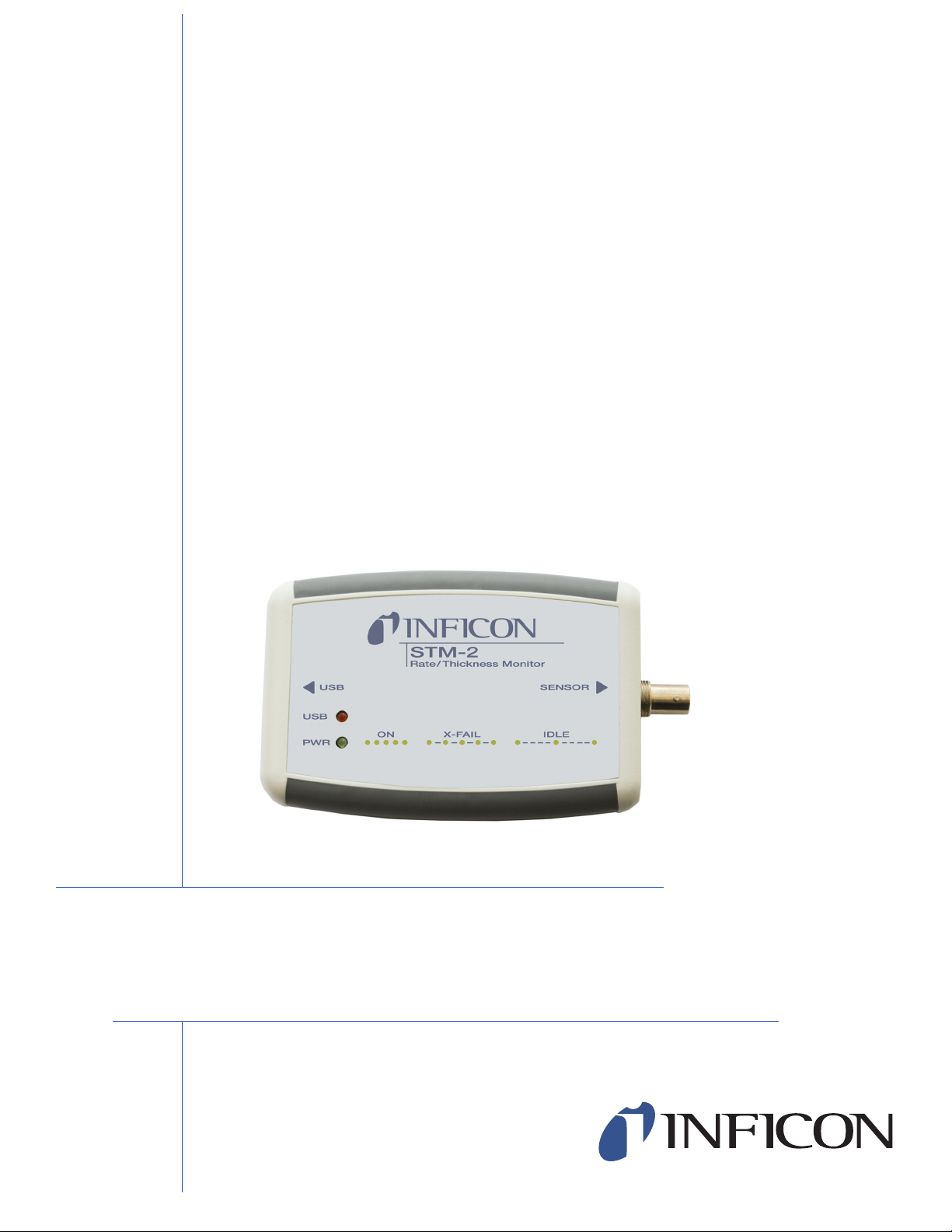
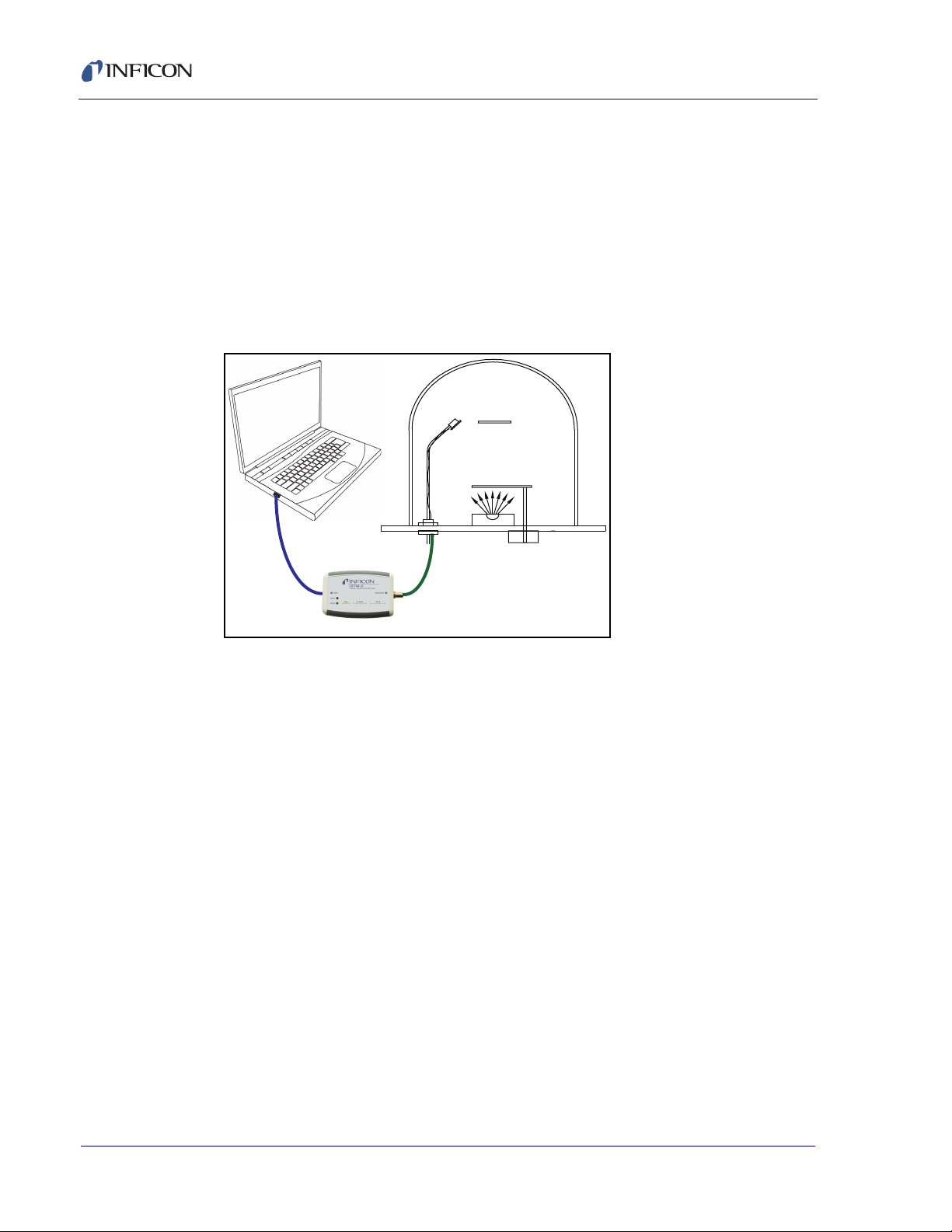
1.1 Introduction
STM-2™ is a USB-powered thin film thickness and rate deposition monitor (see
Figure 1-1). STM-2 provides precise control of thickness or mass deposition
experiments using a USB connection, Windows® or LabVIEW™ software
(provided), and a Windows computer (user supplied).
The STM-2 internal oscillator allows the sensor to be located within 76.2 cm (30 in.)
of STM-2. An external oscillator, PN 783-500-013, can be used when the sensor is
located farther than 101.6 cm (40 in.) from STM-2.
STM-2 can take ten measurements per second. The measurements are shown on
a 0.01Å/s rate display. STM-2 LabVIEW software has an option for multi-layer
mode. This mode enables a Layer Stackup pane, displaying a list of process
layers. It also enables cumulative substrate thickness to be displayed on the
software (see section 4.3.1 on page 4-6).
STM-2 Operating Manual
Chapter 1
Introduction and Specifications
Figure 1-1 STM-2
PN 074-613-P1A
1.1.1 Related Manuals
Sensors are covered in separate manuals. These manuals are contained in the
Thin Film Manuals CD (PN 074-5000-G1), which is part of the ship kit.
PN 074-154—Bakeable Sensor
PN 074-156—Front Load Sensor, Single/Dual
PN 074-157—Sputtering Sensor
PN 074-609—Cool Drawer Sensor, Single/Dual
1 - 1
Page 14
STM-2 Operating Manual
CAUTION
WARNING
WARNING - Risk Of Electric Shock
1.2 Instrument Safety
1.2.1 Definition of Notes, Cautions and Warnings
When using this manual, please pay attention to the notes, cautions and warnings
found throughout. For the purposes of this manual they are defined as follows:
NOTE: Pertinent information that is useful in achieving maximum STM-2 efficiency
when followed.
Failure to heed these messages could result in damage
to STM-2 or the loss of data.
Failure to heed these messages could result in personal
injury.
Dangerous voltages are present, which could result in
personal injury.
PN 074-613-P1A
1 - 2
Page 15
1.2.2 General Safety Information
CAUTION
CAUTION
WARNING
STM-2 contains delicate circuitry, susceptible to
transient power line voltages. Disconnect the USB cord
whenever making any sensor connections or when the
case is open.
Refer all maintenance to qualified personnel.
STM-2 may not be suitable for use with RF sputtering
systems or other electrically noisy environments.
STM-2 Operating Manual
Failure to operate STM-2 in the manner intended by
INFICON can circumvent the safety protection provided
by the instrument and may result in personal injury.
PN 074-613-P1A
1 - 3
Page 16

STM-2 Operating Manual
1.3 How To Contact INFICON
Worldwide customer support information is available under Support >> Support
Worldwide at www.inficon.com:
Sales and Customer Service
Technical Support
Repair Service
When communicating with INFICON about STM-2, please have the following
information readily available:
the Sales Order or Purchase Order number of the STM-2 purchase.
the version of STM-2 software (see section 3.3.3.1 on page 3-18 or section
4.3.7 on page 4-18).
the version of Windows operating system.
adescription of the problem.
an explanation of any corrective action that may have already been attempted.
the exact wording of any error messages that may have been received.
1.3.1 Returning STM-2
Do not return any component of STM-2 to INFICON before speaking with a
Customer Support Representative and obtaining a Return Material Authorization
(RMA) number. STM-2 will not be serviced without an RMA number.
Packages delivered to INFICON without an RMA number will be held until the
customer is contacted. This will result in delays in servicing STM-2.
If returning STM-2 with a crystal sensor or another component potentially exposed
to process materials, prior to being given an RMA number, a completed Declaration
Of Contamination (DOC) form will be required. DOC forms must be approved by
INFICON before an RMA number is issued. INFICON may require that the
component be sent to a designated decontamination facility, not to the factory.
PN 074-613-P1A
1 - 4
Page 17

1.4 Specifications
Compatible Sensor. . . . . . . . . . . . . . Non-shuttered single QCM sensor
Sensor Inputs . . . . . . . . . . . . . . . . . . 1
Sensor Input . . . . . . . . . . . . . . . . . . . Female BNC
Measurement Frequency Range . . . 6.0 to 5.0 MHz (fixed)
Frequency Resolution . . . . . . . . . . . ± 0.03 Hz @ 6 MHz
Measurement Interval. . . . . . . . . . . . 0.10 s
Reference Frequency Stability . . . . . ± 2 ppm
Thickness and Rate
Resolution/Measurement . . . . . . . . . ± 0.037 Å @ tooling/density = 100/1
Thickness Display Resolution . . . . . 1 Å
Interface . . . . . . . . . . . . . . . . . . . . . . USB, 5 m (16.4 ft.) maximum length
1.4.1 Power
STM-2 Operating Manual
Fundamental frequency = 6 MHz
Rated Supply Voltage. . . . . . . . . . . . 400 mA, 5 V (dc)
USB Isolation Voltage. . . . . . . . . . . . 1000 V
USB Isolation Capacitance. . . . . . . . 300 pF typically
1.4.2 Operating Environment
Usage . . . . . . . . . . . . . . . . . . . . . . . . Indoor use only
Operating Temperature . . . . . . . . . . 0 to 50°C (32 to 122°F)
Storage Temperature . . . . . . . . . . . . -10 to 60°C (14 to 140°F)
Humidity . . . . . . . . . . . . . . . . . . . . . . Up to 85% RH, non-condensing
Altitude . . . . . . . . . . . . . . . . . . . . . . . Up to 2000 meters
PN 074-613-P1A
Pollution Degree. . . . . . . . . . . . . . . . 2
1.4.3 Size and Weight
Size . . . . . . . . . . . . . . . . . . . . . . . . . 11.4 x 7.6 x 2.5 cm (4.5 x 3 x 1 in.)
Weight . . . . . . . . . . . . . . . . . . . . . . . 57 g (2 oz.)
1.4.4 Computer Requirements
Operating system . . . . . . . . . . . . . . . Windows 8, Windows 7, Windows Vista,
Windows XP, or Windows 2000
USB Port(s) . . . . . . . . . . . . . . . . . . . One USB 1.1 (or later) port for each STM-2
1 - 5
Page 18

STM-2 Operating Manual
1.5 Unpacking and Inspection
1 Remove STM-2 from its packaging.
2 Carefully examine STM-2 for damage that may have occurred during shipping.
It is especially important to note obvious rough handling on the outside of the
container. Immediately report any damage to the carrier and to INFICON.
NOTE: Do not discard the packaging material until inventory has been taken and
installation is successful.
3 Refer to the invoice and take inventory.
4 To install STM-2, see Chapter 2, Installation.
For additional information or technical assistance, contact INFICON (refer to
section 1.3 on page 1-4).
1.6 Parts and Options Overview
1.6.1 Base Configuration
STM-2 with software and cables . . . PN STM-2
1.6.2 Accessories
5 m (16.4 ft.) USB cable. . . . . . . . . . PN 068-0506
15.2 cm (6 in.) BNC . . . . . . . . . . . . . PN 755-257-G6
1.6.2.1 Oscillator Kit
STM-2 has an internal oscillator, however, an option exists to use an external
oscillator kit to interface the sensor to the controller (see section 2.3 on page 2-4).
3 m (10 ft.) Oscillator Kit. . . . . . . . . . PN 783-500-109-10
7.6 m (25 ft.) Oscillator Kit . . . . . . . . PN 783-500-109-25
15.2 m (50 ft.) Oscillator Kit . . . . . . . PN 783-500-109-50
22.9 m (75 ft.) Oscillator Kit . . . . . . . PN 783-500-109-75
PN 074-613-P1A
1 - 6
Page 19

Oscillator kits include:
These kits are designed for use with the standard in-vacuum cables ranging in
length from 15.2 cm (6 in.) to 78.1 cm (30.75 in.).
1.6.2.2 Sensors
Front Load Single Sensor. . . . . . . . . . . . PN SL-XXXXX
Cool Drawer Single Sensor . . . . . . . . . . PN CDS-XXFXX
Sputtering Sensor. . . . . . . . . . . . . . . . . . PN 750-618-G1
STM-2 Operating Manual
Oscillator. . . . . . . . . . . . . . . . . . . PN 783-500-013
15.2 cm (6 in.) BNC cable . . . . . PN 782-902-011
One of the following:
3 m (10 ft.) BNC Cable . . . . . PN 782-902-012-10
7.6 m (25 ft.) BNC Cable . . . PN 782-902-012-25
15.2 m (50 ft.) BNC Cable . . PN 782-902-012-50
22.9 m (75 ft.) BNC Cable . . PN 782-902-012-75
UHV Bakeable Sensor . . . . . . . . . . . . . . PN BK-A0F
Low Profile Singe Sensor . . . . . . . . . . . . PN 783-500-042
Low Profile Bakeable Single Sensor . . . PN 783-500-009
NOTE: Low Profile Single Sensors also have options with no cooling lines.
NOTE: "X" in part number indicates customer-selectable option,
see www.inficon.com for Sensor Datasheets.
NOTE: Multi-crystal (rotary) sensors and dual sensors should
not be used with STM-2.
PN 074-613-P1A
1 - 7
Page 20

STM-2 Operating Manual
This page is intentionally blank.
1 - 8
PN 074-613-P1A
Page 21

2.1 Installation Requirements
CAUTION
2.1.1 Parts Requirements
STM-2 Monitor
One crystal sensor with feedthrough
One oscillator kit for the crystal sensor
NOTE: The oscillator kit is not required when using the internal oscillator.
Quartz crystals appropriate for the application
One Windows computer meeting minimum specifications (refer to section 1.4
on page 1-5).
STM-2 Operating Manual
Chapter 2
Installation
To maintain proper STM-2 performance, use only
the provided 15.2 cm (6 in.) BNC cable to connect STM-2
or the oscillator to the crystal sensor.
The length of the in-vacuum cable (Front Load and
Sputtering sensors) or electrical conduit tube
(Cool Drawer and Bakeable sensors) must not exceed
78.1 cm (30.75 in.).
PN 074-613-P1A
2 - 1
Page 22
STM-2 Operating Manual
USB
USB
Cable
BNC Cable
Maximum Length
15.2 cm (6 in.)
Substrate
Source
Sensor
Jumpers set
for internal oscillator
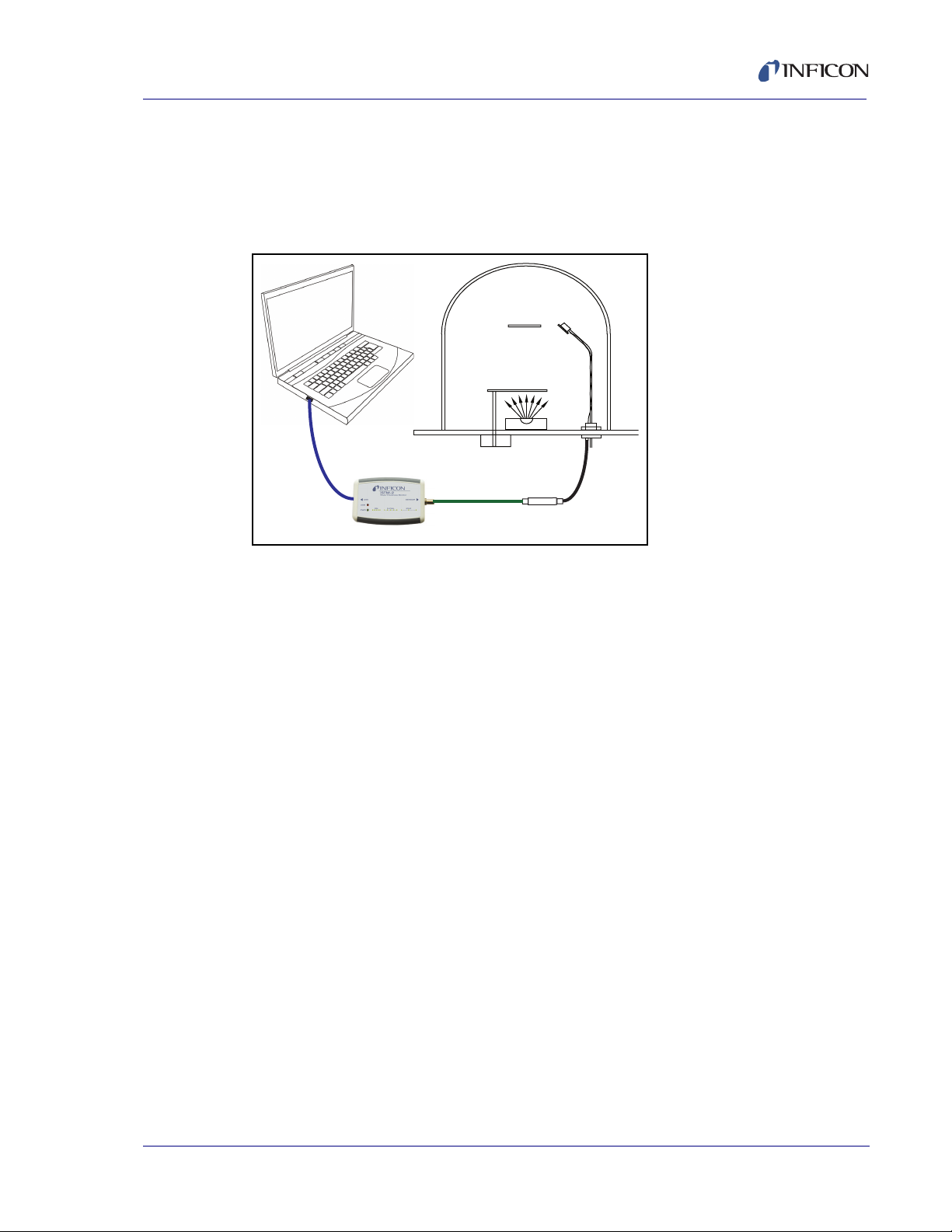
2.2 System Connections
STM-2 can be configured to use either an internal or external oscillator depending
on the internal jumpers. The default jumper setting is to use the internal oscillator.
2.2.1 Internal Oscillator
1 Connect the (provided) USB cable to a computer USB port and to STM-2.
2 Use the (provided) 15.2 cm (6 in.) BNC cable to connect STM-2 to the sensor
feedthrough (see Figure 2-1).
Figure 2-1 Internal oscillator
3 Install and run STM-2 Software or STM-2 LabVIEW Application (see Chapter 3
or Chapter 4).
NOTE: STM-2 Software and STM-2 LabVIEW can be installed and run on the
same computer without interference.
4 The PWR indicator on STM-2 illuminates (see section 2.4.1 on page 2-5).
5 The USB indicator on STM-2 illuminates (see section 2.4.2 on page 2-5).
PN 074-613-P1A
2 - 2
Page 23
2.2.2 External Oscillator
USB
USB
Cable
BNC Cable
Maximum Length
22.9 m (75 ft.)
Substrate
Source
Sensor
Jumpers set
for external oscillator
Oscillator
783-500-013
15.2 cm (6 in.)
BNC Cable
To use an optional external oscillator, the jumpers inside STM-2 must be
repositioned (see section 2.3). The maximum BNC cable length connecting the
external oscillator and STM-2 is 22.9 m (75 ft.) (see Figure 2-2).
Figure 2-2 External oscillator
STM-2 Operating Manual
PN 074-613-P1A
2 - 3
Page 24
STM-2 Operating Manual
CAUTION
CAUTION - Static Sensitive Device
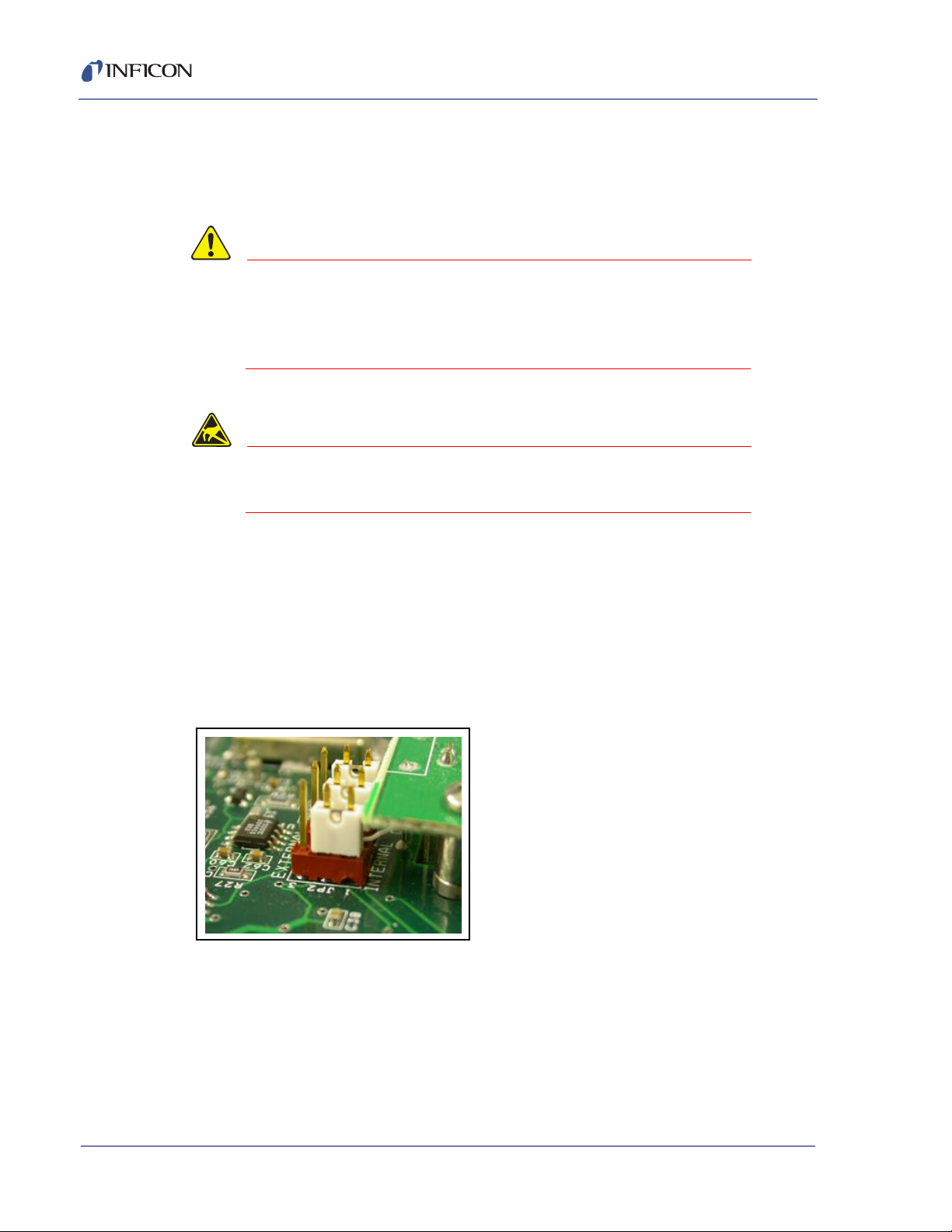
2.3 Switching Between Internal and External Oscillator
Three jumpers must be repositioned inside the STM-2 case to switch between the
internal oscillator and an external oscillator.
STM-2 contains delicate circuitry, susceptible to
transient power line voltages. Disconnect the USB cord
whenever making any sensor connections or when the
case is open.
Observe proper ESD procedures when the STM-2
case is open.
Remove the two phillips screws which secure the back of the case, and remove the
back of the case.
Near the BNC connector are three jumpers on the circuit board, labeled Internal
and External. Move all three jumpers:
To Internal for internal oscillator operation (see Figure 2-3).
To External for external oscillator operation.
Figure 2-3 Jumpers set for internal oscillator operation
PN 074-613-P1A
2 - 4
Page 25

2.4 STM-2 Indicators
2.4.1 Power
Illuminated . . . . . . . . . . . . . . . . . . . . STM-2 is powered up and is connected to a
Flashing fast . . . . . . . . . . . . . . . . . . . STM-2 is powered up but cannot detect a
Blinking slow
(approximately once per second) . . . STM-2 is powered up and the crystal is good,
Extinguished. . . . . . . . . . . . . . . . . . . STM-2 does not have power. Check the USB
STM-2 Operating Manual
good crystal.
The host computer has initialized STM-2 by
returning a reset status when the software
begins communication.
good crystal.
but the computer application has not
initialized STM-2. Once the computer
initializes STM-2 the indicator will illuminate
continuously (see section 6.1.1 on page 6-1).
connection, and make sure the computer is
turned on.
2.4.2 USB
The USB indicator detects communications signal traffic.
Illuminated . . . . . . . . . . . . . . . . . . . . STM-2 is connected and communicating to a
host computer. Communications
sent/received every 100 ms will cause the
indicator to be steadily illuminated.
Flashing . . . . . . . . . . . . . . . . . . . . . . STM-2 is connected and communicating to a
host computer. A flashing indicator will
correspond to the time elapsed between sent
PN 074-613-P1A
Extinguished. . . . . . . . . . . . . . . . . . . STM-2 is not communicating to the
NOTE: STM-x_win32 LabVIEW application software and INFICON STM-2
software will steadily illuminate the indicator due to communications
queries sent every 100 ms. User-created software may not steadily
illuminate the indicator due a longer time period elapsing between
communications queries being sent.
and received communications. A query sent
once per second will correspond to the
indicator flashing approximately once per
second.
computer.
2 - 5
Page 26

STM-2 Operating Manual
This page is intentionally blank.
2 - 6
PN 074-613-P1A
Page 27

STM-2 Software Operation
3.1 Introduction
INFICON STM-2 Software is capable of interfacing up to eight STM-2 instruments
to display Rate, Thickness, Frequency, and Crystal Life for the connected sensors.
STM-2 Software has independent Density, Z-Ratio, and Tooling parameters for
each STM-2 to allow for codeposition monitoring capabilities.
3.2 Installing INFICON STM-2 Software
3.2.1 Installing the Protocol Server
1 Insert the Thin Film Manuals CD into the CD drive on the computer that will
be connected to STM-2.
2 Click Windows Explorer or
File Explorer >> Computer >> (CD drive letter:) >> Common Software.
STM-2 Operating Manual
Chapter 3
3 Double click setup_smdp_svr_lv.exe. The Zip Self-Extractor window will
display.
4 Click Unzip. The SMDP Serial Protocol Server window will display.
5 On the Destination Directory pane, click Browse to select the location where
all software will be installed.
6 Click Next.
7 Read the license agreement.
8 Click I accept License Agreement(s).
9 Click Next.
10 Review the summary of information.
PN 074-613-P1A
11 Click Next. Installation Complete will display.
12 Click Next. The Setup Wizard pane will display.
13 Click Next. The Confirm Installation pane will display.
14 Click Next.
15 Read the license agreement.
16 Click I Agree.
17 Click Next. Installation Complete will display.
18 Click Close.
19 Click Close on the Zip Self-Extractor.
3 - 1
Page 28

STM-2 Operating Manual
3.2.2 Installing the INFICON STM-2 Software and Device Drivers
1 Insert the Thin Film Manuals CD into the CD drive of the computer that will be
connected to STM-2.
2 Click Windows Explorer or File Explorer >> Computer >> (CD drive letter:)
>> STM-2.
3 Double click STM-2 v1.0.0 Setup.exe. The STM-2 - InstallShield Wizard will
display.
4 Click Next.
5 Review the summary of information.
6 Select I accept the terms in the license agreement.
7 Click Next.
8 Click Change to select the location of the software files to be installed.
9 Click Next.
10 Click Install.
11 Click Finish. The USB Installer - InstallShield Wizard window will display.
12 Click Next.
13 Review the summary of information.
14 Select I accept the terms in the license agreement.
15 Click Next.
16 Enter User Name and Organization information.
17 Click Next.
18 Click Install.
19 Click Finish. The CP210x USB to UART Bridge Driver Installer window will
display.
20 Click Next.
21 Review the summary of information.
22 Select I accept this agreement.
23 Click Next.
24 Click Finish.
PN 074-613-P1A
3 - 2
Page 29
STM-2 Operating Manual
3.2.3 Starting INFICON STM-2 Software
3.2.3.1 Starting the Software in Windows XP or Windows 7
1 Click Start >> All Programs >> INFICON >> STM-2.
2 The STM-2 window will display (see Figure 3-1).
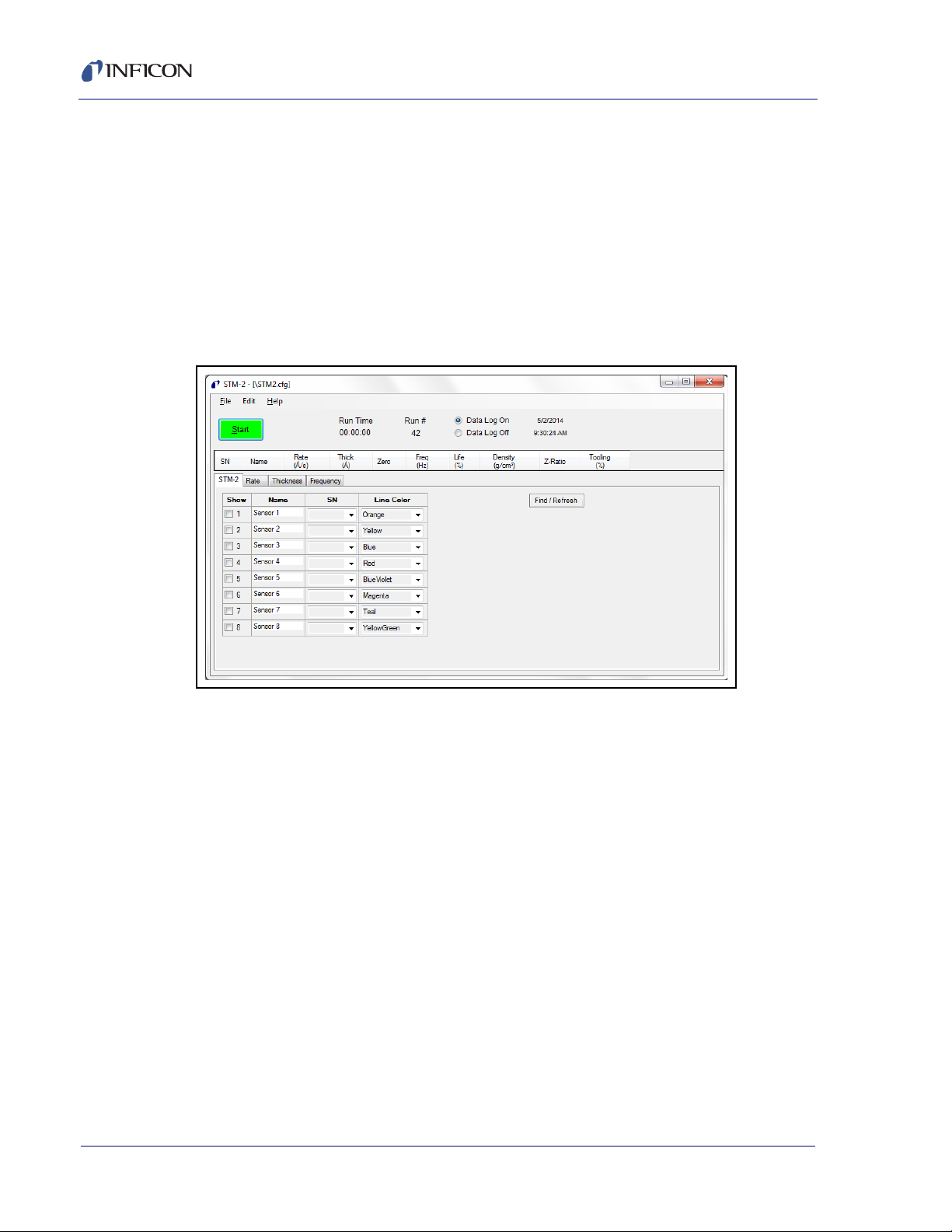
Figure 3-1 STM-2 window
3.2.3.2 Starting the Software in Windows 8
1 In the Start window, click the STM-2 icon.
2 If the icon cannot be found:
2a Click Search >> Apps.
2b Type STM in the Search text box.
2c Click the STM-2 icon.
PN 074-613-P1A
3 - 3
Page 30
STM-2 Operating Manual
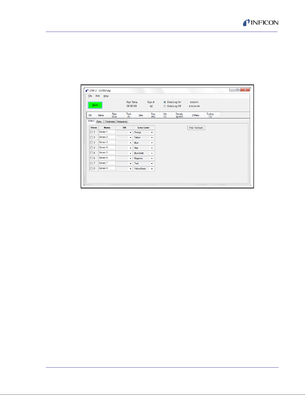
3.3 STM-2 Window
The STM-2 window displays Serial Number (SN), (Sensor) Name, Rate,
Thick(ness) of the film, Zero thickness button, Freq(uency), crystal Life, Density of
the film, Z-Ratio, and Tooling for the connected sensor and process material. This
window also provides a button to Start, Stop, or Pause/Resume monitoring. Also,
the Run Time of the Process, the Run #, a selection for Data Log(ging) to be turned
on and off, and the current date and time are displayed. From this window, there is
also access to STM-2, Rate, Thickness, and Frequency tabs as well as the File,
Edit, and Help menus for customization and configuration (see Figure 3-2).
Figure 3-2 STM-2 window
3 - 4
File menu (see section 3.3.1 on page 3-6)
Edit menu (see section 3.3.2 on page 3-8)
Help menu (see section 3.3.3 on page 3-18)
STM-2 tab (see section 3.3.4 on page 3-19)
Rate tab (see section 3.3.5 on page 3-20)
Thickness tab (see section 3.3.6 on page 3-21)
Frequency tab (see section 3.3.7 on page 3-22)
PN 074-613-P1A
Page 31

STM-2 Operating Manual
STM-2 window
Start/Stop . . . . . . . . . . . . . . . . . . . . Click to Start monitoring. Start changes to
Stop. Stop will halt the process and data log
until Start is clicked.
Pause/Resume . . . . . . . . . . . . . . . . Pause is displayed while monitoring to pause
the monitoring. Pause stops the monitoring
at its current time and changes to Resume
when clicked. Resume will continue
monitoring and increment the Run Time.
Run Time . . . . . . . . . . . . . . . . . . . . . Time that the current run number has been
being monitored; resets when Start is clicked,
stops and continues when Pause/Resume
are clicked.
Run # . . . . . . . . . . . . . . . . . . . . . . . . Incremented when Start is clicked.
Data Log On/Data Log Off . . . . . . . Select Data Log On to enable data logging.
Select Data Log Off to disable data logging.
Date . . . . . . . . . . . . . . . . . . . . . . . . . Current date in month/day/year format.
Time . . . . . . . . . . . . . . . . . . . . . . . . . Current time in hh:mm:ss format.
SN . . . . . . . . . . . . . . . . . . . . . . . . . . Serial Number of STM-2(s) selected to view
(see section 3.3.4 on page 3-19).
Name . . . . . . . . . . . . . . . . . . . . . . . . Name of STM-2(s) selected to view (see
section 3.3.4 on page 3-19).
Rate . . . . . . . . . . . . . . . . . . . . . . . . . Rate, displayed in Å/s or Mass Rate
displayed in ng/cm
2
/s, of STM-2(s) selected
to view (see section 3.3.4 on page 3-19).
Thick . . . . . . . . . . . . . . . . . . . . . . . . Thickness displayed in Å or kÅ, or Mass in
2
µg/cm
, of STM-2(s) selected to view (see
section 3.3.2.2 on page 3-16).
PN 074-613-P1A
Zero . . . . . . . . . . . . . . . . . . . . . . . . . Click to zero thickness.
Freq . . . . . . . . . . . . . . . . . . . . . . . . . Frequency of the crystal connected to
STM-2(s) selected to view (see section 3.3.4
on page 3-19). This changes to !XTAL FAIL!
upon a crystal failure.
Life . . . . . . . . . . . . . . . . . . . . . . . . . . Percentage of crystal life remaining,
decremented from 100%.
NOTE: This is based on a 6 MHz crystal.
3 - 5
Page 32

STM-2 Operating Manual
Density . . . . . . . . . . . . . . . . . . . . . . 0.5 to 99.99
Value in grams per cubic centimeter of
material being deposited. Click in the text box
to edit the density value. For a list of common
material densities, see Appendix A.
Z-Ratio. . . . . . . . . . . . . . . . . . . . . . . 0.1 to 9.999
Z-Ratio of material being deposited. Click in
the text box to edit the Z-Ratio value. For a
list of Z-Ratios for common materials, see
Appendix A.
Tooling . . . . . . . . . . . . . . . . . . . . . . 10 to 399
Tooling of the sensor connected to STM-2.
Click in the text box to edit the Tooling value.
To determine tooling, see section 7.3 on
page 7-2.
3.3.1 File Menu
Click File to open or save a configuration file, to print or capture screen images, or
to exit INFICON STM-2 Software (see Figure 3-3).
Figure 3-3 File menu
PN 074-613-P1A
3 - 6
Page 33

3.3.1.1 Open Configuration
Click to select a file location of a configuration file and load that configuration file
into INFICON STM-2 Software (see Figure 3-4).
Figure 3-4 Open Configuration window
STM-2 Operating Manual
3.3.1.2 Save Configuration
Click to save the current configuration. The default configuration file is STM2.cfg.
3.3.1.3 Save Configuration As
Click to select a name and location to save the configuration file (see Figure 3-5).
Figure 3-5 Save As window
PN 074-613-P1A
3 - 7
Page 34

STM-2 Operating Manual
3.3.1.4 Print
Click to print all of the current views of the STM-2 window (refer to Figure 3-2 on
page 3-4) or, print only the current window displayed.
NOTE: If the print setup window has been configured once during a session, the
parameters selected will not be able to be changed until the software is
exited and reloaded.
3.3.1.5 Screen Image to File
This list item will display a list of options regarding screen images.
Current View to JPG . . . . . . . . . . . Places a JPEG image of the current window
All Views to JPGs. . . . . . . . . . . . . . Places JPEG images of the current views of
into the default Captures folder located in
Local Disk (C:) >> Program Files >>
INFICON >> STM-2 >> captures.
the STM-2 window into the default Captures
folder located in Local Disk (C:) >>
Program Files >> INFICON >> STM-2 >>
captures.
Select JPG Folder . . . . . . . . . . . . . Displays a window to select the location and
3.3.2 Edit Menu
Provides options to customize graph, display, and sample settings (see Figure
3-6).
Figure 3-6 Edit menu
3.3.2.1 Graph Settings
Click to display a window to configure the settings for Rate, Thickness, and
Frequency graphs. Also provides customization of line colors, axis formatting, and
scrolling.
NOTE: Graph Settings is disabled while monitoring.
name of the folder where the JPEG screen
images will be saved.
PN 074-613-P1A
3 - 8
Page 35

3.3.2.1.1 X Axis & Colors
Figure 3-7 X Axis & Colors tab
X Axis Width . . . . . . . . . . . . . . . . . . 1 minute to 120 minutes, 59 seconds
STM-2 Operating Manual
Use the spin box to enter the minutes and
seconds displayed as a maximum x-axis
value on all of the graphs.
X Text Interval. . . . . . . . . . . . . . . . . 1 to 480 seconds
Displays the time on the x-axis of all graphs
for the selected interval.
X Axis Scrolling . . . . . . . . . . . . . . . Select Step 5%, 25%, 50%, 75%, or 100%, to
determine the percentage of the graph that is
available for new data once the plot reaches
the maximum x-axis value.
Line Colors . . . . . . . . . . . . . . . . . . . Use the drop-down list box to select a color
to correspond with each STM-2 connected.
NOTE: This will also change the Line Color
on the STM-2 tab (see Figure 3-15
PN 074-613-P1A
on page 3-19).
Click Apply to update the display with any changes made. Click OK to save
changes and exit the Configure Graph(s) window. Click Cancel to cancel any
changes and exit the Configure Graph(s) window.
3 - 9
Page 36

STM-2 Operating Manual
3.3.2.1.2 Rate Tab
Figure 3-8 Rate tab
Y Axis Range pane
Min. . . . . . . . . . . . . . . . . . . . . . . . . . -100.00 to 100.00
Minimum y-axis value displayed on the Rate
graph.
NOTE: Minimum value must be less than the
value entered for the maximum.
Max. . . . . . . . . . . . . . . . . . . . . . . . . . -100.00 to 100.00
Maximum y-axis value displayed on the Rate
graph.
NOTE: Maximum value must be greater
than the value entered for the
minimum.
Axis Ticks pane
X Step . . . . . . . . . . . . . . . . . . . . . . . 0 to 100.0
Displays unlabeled x-axis ticks at the interval
selected.
NOTE: Ticks are only visible if Visible has
been selected. Clear to disable ticks.
Y Step . . . . . . . . . . . . . . . . . . . . . . . 0 to 100.0
Displays unlabeled y-axis ticks at the interval
selected.
PN 074-613-P1A
3 - 10
NOTE: Ticks are only visible if Visible has
been selected. Clear to disable ticks.
Page 37

STM-2 Operating Manual
Graph Grid pane
X Spacing . . . . . . . . . . . . . . . . . . . . 0 to 100.0
Displays x-axis grid at the interval selected.
NOTE: Grid is only visible at the selected
interval when Visible has been
selected. Clear to disable grid lines.
Y Spacing . . . . . . . . . . . . . . . . . . . . 0 to 100.0
Displays y-axis grid at the interval selected.
NOTE: Grid is only visible at the selected
interval when Visible has been
selected. Clear to disable grid lines.
Solid Line Y=0. . . . . . . . . . . . . . . . . Select to display a solid line on the Rate
graph at Y=0. Clear to remove the solid line
at Y=0.
Graph Title pane
Edit text box to rename the Rate graph.
NOTE: Click Apply to update the display with any changes made. Click OK to
save changes and exit the Configure Graph(s) window. Click Cancel to
cancel any changes and exit the Configure Graph(s) window.
PN 074-613-P1A
3 - 11
Page 38

STM-2 Operating Manual
3.3.2.1.3 Thickness Tab
Figure 3-9 Thickness tab
Y Axis Range pane
Min. . . . . . . . . . . . . . . . . . . . . . . . . . -100.00 to 100.00
Minimum y-axis value displayed on the
Thickness graph.
NOTE: Minimum value must be less than the
value entered for the maximum.
Max. . . . . . . . . . . . . . . . . . . . . . . . . . -100.00 to 100.00
Maximum y-axis value displayed on the
Thickness graph.
NOTE: Maximum value must be greater
than the value entered for the
minimum.
Axis Ticks pane
X Step . . . . . . . . . . . . . . . . . . . . . . . 0 to 100.0
Displays unlabeled x-axis ticks at the interval
selected.
NOTE: Ticks are only visible if Visible has
been selected. Clear to disable ticks.
Y Step . . . . . . . . . . . . . . . . . . . . . . . 0 to 100.0
Displays unlabeled y-axis ticks at the interval
selected.
PN 074-613-P1A
3 - 12
NOTE: Ticks are only visible if Visible has
been selected. Clear to disable ticks.
Page 39

STM-2 Operating Manual
Graph Grid pane
X Spacing . . . . . . . . . . . . . . . . . . . . 0 to 100.0
Displays x-axis grid at the interval selected.
NOTE: Grid is only visible at the selected
interval when Visible has been
selected. Clear to disable grid lines.
Y Spacing . . . . . . . . . . . . . . . . . . . . 0 to 100.0
Displays y-axis grid at the interval selected.
NOTE: Grid is only visible at the selected
interval when Visible has been
selected. Clear to disable grid lines.
Solid Line Y=0. . . . . . . . . . . . . . . . . Select to display a solid line on the Thickness
graph at Y=0. Clear to remove the solid line
at Y=0.
Graph Title pane
Edit text box to rename the Thickness graph.
NOTE: Click Apply to update the display with any changes made. Click OK to
save changes and exit the Configure Graph(s) window. Click Cancel to
cancel any changes and exit the Configure Graph(s) window.
PN 074-613-P1A
3 - 13
Page 40

STM-2 Operating Manual
3.3.2.1.4 Frequency Tab
Figure 3-10 Frequency tab
Y Axis Range pane
Min. . . . . . . . . . . . . . . . . . . . . . . . . . 4.000000 to 6.100000 MHz
Minimum y-axis value displayed on the
Frequency graph.
NOTE: Minimum value must be less than the
value entered for the maximum.
Max. . . . . . . . . . . . . . . . . . . . . . . . . . 4.000000 to 6.100000 MHz
Maximum y-axis value displayed on the
Frequency graph.
NOTE: Maximum value must be greater
than the value entered for the
minimum.
Axis Ticks pane
X Step . . . . . . . . . . . . . . . . . . . . . . . 0 to 100
Displays unlabeled x-axis ticks at the interval
selected.
NOTE: Ticks are only visible if Visible has
been selected. Clear to disable ticks.
Y Step . . . . . . . . . . . . . . . . . . . . . . . 0.000000 to 100.000000
Displays unlabeled y-axis ticks at the interval
selected.
PN 074-613-P1A
3 - 14
NOTE: Ticks are only visible if Visible has
been selected. Clear to disable ticks.
Page 41

STM-2 Operating Manual
Graph Grid pane
X Spacing . . . . . . . . . . . . . . . . . . . . 0 to 100
Displays x-axis grid at the interval selected.
NOTE: Grid is only visible at the selected
interval when Visible has been
selected. Clear to disable grid lines.
Y Spacing . . . . . . . . . . . . . . . . . . . . 0.000000 to 100.000000
Displays y-axis grid at the interval selected.
NOTE: Grid is only visible at the selected
interval when Visible has been
selected. Clear to disable grid lines.
Graph Title pane
Edit text box to rename the Frequency graph.
NOTE: Click Apply to update the display with any changes made. Click OK to
save changes and exit the Configure Graph(s) window. Click Cancel to
cancel any changes and exit the Configure Graph(s) window.
PN 074-613-P1A
3 - 15
Page 42

STM-2 Operating Manual
3.3.2.2 Display Settings
Click to display a window to configure the settings for Rate Resolution, Filtering,
Format, and View of the STM-2 window (see Figure 3-11).
Figure 3-11 Display Settings window
Rate Resolution . . . . . . . . . . . . . . . Use the drop-down list box to select 0.0 or
Filtering . . . . . . . . . . . . . . . . . . . . . . 1 to 99
0.00 as the rate resolution to be displayed on
the STM-2 window.
Use the spin box to enter the number of
samples to be averaged together for the
STM-2 window Rate display.
NOTE: This value will not affect graphs or
data logs. Use the Samples
Averaged parameter (see section
3.3.2.3) for averaging to affect all
displays and data logs.
Format . . . . . . . . . . . . . . . . . . . . . . . Select Thickness in kÅ, Thickness in Å, or
Mass in µg/cm
2
to be displayed on the
STM-2 window and on the Thickness graph.
NOTE: Mass in µg/cm
a Mass Rate in ng/cm
2
will display Rate as
2
/s.
View/Edit . . . . . . . . . . . . . . . . . . . . . Select Application On Top to display the
STM-2 window in front of all other open
windows. Select Lock Parameters to
disable editing of Density, Z-Ratio, and
Tooling on the STM-2 window.
PN 074-613-P1A
3 - 16
Page 43

3.3.2.3 Sample Settings
Click to display a window to configure the settings for data logging, display, and
graphs (see Figure 3-12).
NOTE: Sample Settings is disabled while monitoring.
Figure 3-12 Sample Settings window
STM-2 Operating Manual
Samples averaged . . . . . . . . . . . . . 1 to 50
Use the spin box to enter the number of
samples averaged for the display, graphs,
and data logging.
Logging Rate . . . . . . . . . . . . . . . . . 1 to 120
Use the spin box to select the logging rate. A
Logging Rate of 1 will log every averaged
measurement.
Logging Interval . . . . . . . . . . . . . . . Displays the data logging period in seconds.
Overwrite. . . . . . . . . . . . . . . . . . . . . Select to overwrite the current data log with
new data.
PN 074-613-P1A
Append . . . . . . . . . . . . . . . . . . . . . . Select to add new data log information to
current data log.
Run# . . . . . . . . . . . . . . . . . . . . . . . . Select to create a new data log named with
the run number being logged.
Select. . . . . . . . . . . . . . . . . . . . . . . . Click to select the name and location of data
log files.
View . . . . . . . . . . . . . . . . . . . . . . . . . Click to view the current data log.
3 - 17
Page 44

STM-2 Operating Manual
3.3.3 Help Menu
Figure 3-13 Help menu
About. . . . . . . . . . . . . . . . . . . . . . . . Click to view the About window (see section
3.3.3.1 About Window
Displays the version number of INFICON STM-2 Software, copyright information,
and the location of the software files (see Figure 3-14).
Figure 3-14 About window
3.3.3.1).
3 - 18
PN 074-613-P1A
Page 45

3.3.4 STM-2 Tab
Figure 3-15 STM-2 tab
Show . . . . . . . . . . . . . . . . . . . . . . . . Select the sensors to be displayed on the
STM-2 Operating Manual
STM-2 window.
Name . . . . . . . . . . . . . . . . . . . . . . . . Edit the name of the sensor. This name will
be displayed on the STM-2 window if
selected.
SN . . . . . . . . . . . . . . . . . . . . . . . . . . Use the drop-down list box to select the serial
number of the connected STM-2 associated
with the named sensor.
Line Color . . . . . . . . . . . . . . . . . . . . Use the drop-down list box to select a color
to correspond with each STM-2 connected.
NOTE: This will also change the Line Color
on the X Axis & Colors tab of the
Graph Settings window (refer to
PN 074-613-P1A
Figure 3-7 on page 3-9).
Find/Refresh . . . . . . . . . . . . . . . . . . Click to Find or Refresh connected STM-2(s).
3 - 19
Page 46

3.3.5 Rate Tab
Displays a graph of Rate and Time for the selected STM-2(s) (see Figure 3-16).
Figure 3-16 Rate tab
STM-2 Operating Manual
3 - 20
PN 074-613-P1A
Page 47

3.3.6 Thickness Tab
Displays a graph of Thickness or Mass and Time for the selected STM-2(s) (see
Figure 3-17).
Figure 3-17 Thickness tab
STM-2 Operating Manual
PN 074-613-P1A
3 - 21
Page 48

STM-2 Operating Manual
3.3.7 Frequency Tab
Displays a graph of Frequency and Time for the selected STM-2(s) (see Figure
3-18).
Figure 3-18 Frequency tab
3 - 22
PN 074-613-P1A
Page 49

STM-2 Operating Manual
STM-2 LabVIEW Operation
4.1 Introduction
STM-2 LabVIEW Application is capable of displaying Rate, Thickness, and Crystal
Life for one STM-2 and the connected sensor. STM-2 LabVIEW Application has the
option to use Multi-layer mode to enable a cumulative Substrate Thickness and
independent Density, Z-Ratio, Tooling, and Sample parameters for each film to
allow for multi-layer monitoring capabilities. STM-2 LabVIEW Application can also
operate in Simulate mode without a connected STM-2.
4.2 Installing the STM-2 LabVIEW Application
4.2.1 Installing the Protocol Server
1 Insert the Thin Film Manuals CD into the CD drive on the computer that will
be connected to STM-2.
Chapter 4
2 Click Windows Explorer or
File Explorer >> Computer >> (CD drive letter:) >> Common Software.
3 Double click setup_smdp_svr_lv.exe. The Zip Self-Extractor window will
display.
4 Click Unzip. The SMDP Serial Protocol Server window will display.
5 On the Destination Directory pane, click Browse to select the location where
all software will be installed.
6 Click Next.
7 Read the license agreement.
8 Click I accept License Agreement(s).
9 Click Next.
PN 074-613-P1A
10 Review the summary of information.
11 Click Next. Installation Complete will display.
12 Click Next. The Setup Wizard pane will display.
13 Click Next. The Confirm Installation pane will display.
14 Click Next.
15 Read the license agreement.
16 Click I Agree.
17 Click Next. Installation Complete will display.
18 Click Close.
19 Click Close on the Zip Self-Extractor.
4 - 1
Page 50

STM-2 Operating Manual
4.2.2 Installing the LabVIEW Application and Device Drivers
1 Insert the Thin Film Manuals CD into the CD drive on the computer that will
be connected to STM-2.
2 Click Windows Explorer or
File Explorer >> Computer >> (CD drive letter:) >> STM-2 >> TOOLS >>
main app.
3 Double click setup_stm-x_win32.exe. The Zip Self-Extractor window will
display.
4 Click Unzip. The Sycon STM-x_win32 window will display.
5 On the Destination Directory pane, click Browse to select the location where
all software will be installed.
6 Click Next.
7 Review the summary of information.
8 Click Next. Installation Complete will display.
9 Click Next. The Silicon Laboratories CP210x VCP Drivers for Windows
2000/XP/2003 Server/Vista window will display.
10 Click Next.
11 Read the license agreement.
12 Click I accept the terms of the license agreement.
13 Click Next.
14 On the Choose Destination Location pane, click Browse to select the
location where all drivers will be installed.
15 Click Next.
16 Click Install. The InstallShield Wizard Complete pane will display.
17 Select Launch the CP210x VCP Driver Installer.
18 Click Finish. The Silicon Laboratories CP210x USB to UART Bridge Driver
Installer window will display.
19 Click Change Install Location to select the location where all drivers will be
installed.
20 Click Install. The Success window will display.
21 Click OK.
22 Click Close on the Zip Self-Extractor.
PN 074-613-P1A
4 - 2
Page 51

STM-2 Operating Manual
4.2.3 Starting the STM-2 LabVIEW Application
4.2.3.1 Starting the Software in Windows XP or Windows 7
1 Click Start >> All Programs >> Sycon >> STM-x_win32 >> STM-x_win32.
2 The STM-x_win32.VI window will display (see Figure 4-1).
Figure 4-1 STM-x_win32.VI initial display
4.2.3.2 Starting the Software in Windows 8
1 In the Start window, click the STM-x_win32 icon.
2 If the icon cannot be found:
2a Click Search >> Apps.
PN 074-613-P1A
2b Type STM in the Search text box.
2c Click the STM-x_win32 icon.
4 - 3
Page 52

STM-2 Operating Manual
4.3 STM-x_win32.VI Window
The STM-x_win32.VI window displays Rate, Film Thick(ness), and Substrate
Thick(ness) for the connected sensor. This window also provides an indicator for a
crystal fail (Xtal OK?), Running time, Life percentage, Run number, Logging status,
and Film name as well as customizable display parameters, graphical information,
and access to Setup, Operate, Films, Rate Graph, Mass/Thick Graph, Frequency
Graph, and Help/About tabs (see Figure 4-2).
NOTE: Right-click and select Description and Tip for additional information.
Figure 4-2 STM-x_win32.VI live display
4 - 4
Setup tab (see section 4.3.1 on page 4-6)
Operate tab (see section 4.3.2 on page 4-10)
Films tab (see section 4.3.3 on page 4-12)
Rate Graph tab (see section 4.3.4 on page 4-14)
Mass/Thick Graph tab (see section 4.3.5 on page 4-15)
Frequency Graph tab (see section 4.3.6 on page 4-16)
Help/About tab (see section 4.3.7 on page 4-18)
PN 074-613-P1A
Page 53

STM-2 Operating Manual
Good
Crystal
Crystal
Fail
Sycon STM Instrument Interface pane
Press to Halt . . . . . . . . . . . . . . . . . . Click to exit STM-x_win32.VI application.
Rate . . . . . . . . . . . . . . . . . . . . . . . . . Deposition rate based on the frequency of
the crystal.
Film Thick/Film Mass . . . . . . . . . . . Thickness or Mass of Film being monitored.
Substrate Thick/Substrate Mass. . Accumulated Thickness or Mass of all layers.
Clear Graphs. . . . . . . . . . . . . . . . . . Clears Rate, Mass/Thick, and Frequency
graphs.
Xtal OK? . . . . . . . . . . . . . . . . . . . . . Illuminated light green when a good crystal is
connected; dark green when a crystal fail has
occurred (see Figure 4-3).
Figure 4-3 Xtal OK
RUNNING/PAUSED. . . . . . . . . . . . . Running changes to Paused if the process is
paused on the Operate tab (see section
4.3.2 on page 4-10).
h:mm:ss . . . . . . . . . . . . . . . . . . . . . Time that the current run number has been
running; resets with each new run.
Life/XTAL FAIL . . . . . . . . . . . . . . . . Percentage of crystal life remaining,
decremented from 100%; changes to XTAL
FAIL upon a crystal failure.
PN 074-613-P1A
RUN #. . . . . . . . . . . . . . . . . . . . . . . . Incremented when New run is clicked on the
Operate tab (see section 4.3.2 on page
4-10).
LOGGING OFF/LOGGING ON . . . . Logging off changes to logging on when data
logging is enabled by selecting OFF/ON in
the Datalog pane of the Setup tab (see
section 4.3.1).
Film . . . . . . . . . . . . . . . . . . . . . . . . . Name of film being monitored is displayed.
4 - 5
Page 54

4.3.1 Setup
STM-2 Operating Manual
Figure 4-4 Setup tab
Connection pane
Find Instrument . . . . . . . . . . . . . . . Click to search for instruments (see Figure
4-5).
Figure 4-5 Find instrument window
Search for STM-1s . . . . . . . . . . Automatically detects connected STM-1s.
Search for STM-2s . . . . . . . . . . Automatically detects connected STM-2s.
Manual Connection . . . . . . . . . See section 4.3.1.1 on page 4-8.
Simulate . . . . . . . . . . . . . . . . . . See section 4.3.1.2 on page 4-9
.
Cancel . . . . . . . . . . . . . . . . . . . . Closes Find Instrument window.
PN 074-613-P1A
4 - 6
Text Box . . . . . . . . . . . . . . . . . . . . . Displays the connection information for the
connected STM-2.
Page 55

STM-2 Operating Manual
Display pane
Thickness . . . . . . . . . . . . . . . . . . . . Displays Rate units of Å/s,
Film Thick units of kÅ, and
Substrate Thick units of kÅ on the
STM-x_win32.VI window.
Mass . . . . . . . . . . . . . . . . . . . . . . . . Displays Rate units of µg*s/cm², Film Mass
units of µg/cm², and Substrate Mass units of
µg/cm² on the STM-x_win32.VI window.
Multi-layer mode. . . . . . . . . . . . . . . When enabled, displays Substrate
Thick/Substrate Mass on the
STM-x_win32.VI window and displays the
New Layer button and Layer Stackup pane
on the Operate tab.
Run# . . . . . . . . . . . . . . . . . . . . . . . . Manually increment the Run number on the
Sycon STM Instrument Interface pane.
Datalog pane
OFF/ON . . . . . . . . . . . . . . . . . . . . . . Enables data logging.
Log Period. . . . . . . . . . . . . . . . . . . . hh:mm:ss
Assigns a data log period to record
monitored values. Records:
Date
Time
Running
Life
Run#
Logging on
Film
Rate
Film Thickness/Film Mass
PN 074-613-P1A
Substrate Thickness/Substrate Mass
Frequency
Run# . . . . . . . . . . . . . . . . . . . . . . . . Names the file with the Run number.
STMxlog.txt . . . . . . . . . . . . . . . . . . . Names the file with STMxlog.
Tab delimiter . . . . . . . . . . . . . . . . . . Records values in data logs delimited with
tabs to separate each field.
Comma delimiter . . . . . . . . . . . . . . Records values in data logs with commas to
separate each field.
View Log . . . . . . . . . . . . . . . . . . . . . Click to view current data log.
Logfile folder. . . . . . . . . . . . . . . . . . Click the folder icon ( ) to select the
location to save data log files.
4 - 7
Page 56
STM-2 Operating Manual
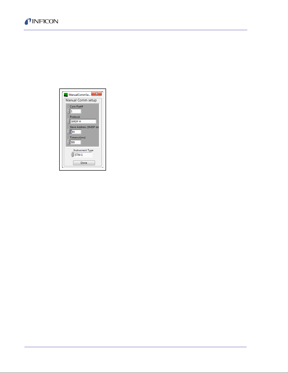
4.3.1.1 Manual Connection
STM-x_win32.VI software allows the creation of a manual connection to STM-1,
STM-2, or Simulate. To enable a manual connection, click Find Instruments on
the Setup tab and click Manual connection. The Manual Comm setup window
will display. Select the correct Com Port#, Protocol, Slave Address,
Timeout(ms), and Instrument Type. Click Done (see Figure 4-6).
Figure 4-6 Manual connection
Comm Ports . . . . . . . . . . . . . . . . . . 1 to 255
Enter the communications port connected to
STM-2.
Protocol. . . . . . . . . . . . . . . . . . . . . . Sycon, SMDP L, SMDP M, SMDP H
Enter the STM-2 communications protocol
and baud rate:
Sycon: Sycon protocol (9.6 kbps)
SMDP L: SMDP protocol (9.6 kbps)
SMDP M: SMDP protocol (38.4 kbps)
SMDP H: SMDP protocol (115.2 kbps)
Slave Address . . . . . . . . . . . . . . . . 1 to 255
Enter the STM-2 communication slave
address.
Timeout . . . . . . . . . . . . . . . . . . . . . . 0 to 4294967295
Communications will timeout when the value
entered in milliseconds has elapsed.
PN 074-613-P1A
4 - 8
Instrument Type . . . . . . . . . . . . . . . STM-1, STM-2, Simulate
Done . . . . . . . . . . . . . . . . . . . . . . . . Close window.
Page 57

4.3.1.2 Simulate Mode
STM-x_win32.VI software allows a simulated deposition without connection to
STM-2. To enable simulate mode, click Find Instruments on the Setup tab and
click Simulate. The Sim Rate hz/sec box will display on the Setup tab. Enter the
rate simulation in hertz per second (see Figure 4-7).
Figure 4-7 Simulate mode
STM-2 Operating Manual
With a rate of hertz per second defined, the software will convert the change in
frequency to Rate in angstroms per second or microgram second per centimeter
squared based on the selection of Thickness or Mass on the Display pane.
PN 074-613-P1A
4 - 9
Page 58

4.3.2 Operate
Figure 4-8 Operate tab
STM-2 Operating Manual
Change Film . . . . . . . . . . . . . . . . . . Changes the active film. Clicking this opens
the FilmPicker.vi window that displays films
to run (see Figure 4-9). Existing thickness is
not zeroed, the thickness is recalculated with
the new Z-Ratio and tooling.
Figure 4-9 FilmPicker.vi window
NOTE: If a film is not displayed in this
window, the film will need to be
added by clicking Edit Films on the
Films tab (see section 4.3.3).
PN 074-613-P1A
4 - 10
Page 59

STM-2 Operating Manual
New Layer . . . . . . . . . . . . . . . . . . . . Opens the FilmPicker.vi window and adds
the selection as a new layer to the Layer
Stackup.
New run . . . . . . . . . . . . . . . . . . . . . . Clears the Layer Stackup, opens the
FilmPicker.vi window, adds the selection as
a new layer to the Layer Stackup, and
increments the Run number.
Pause/Resume . . . . . . . . . . . . . . . . Changes the Pause button to Resume and
changes the background of the Sycon STM
Instrument Interface pane to red. Pauses
data logging and graphing until Resume is
clicked.
ZERO TIMER . . . . . . . . . . . . . . . . . . Resets the timer on the Sycon STM
Instrument Interface pane.
ZERO FILM THK . . . . . . . . . . . . . . . Resets Film Thickness or Film Mass.
Layer Stackup. . . . . . . . . . . . . . . . . Lists Film Name and current Thickness or
Mass for each layer in the process.
PN 074-613-P1A
4 - 11
Page 60

4.3.3 Films
STM-2 Operating Manual
Displays a list of films set up for the process in the Films Database. The film
outlined in blue is the active film.
Figure 4-10 Films tab
Edit films . . . . . . . . . . . . . . . . . . . . . Displays FilmEditor.vi window to add or
remove films to the Films Database (see
Figure 4-11). Each of the following
parameters can be manually edited or input
using the Materials button:
Name
Density
Z-Ratio
Too lin g
# samples
Notes
NOTE: User defined films can be input by
typing over existing values or by
entering data into empty cells.
PN 074-613-P1A
4 - 12
Page 61

STM-2 Operating Manual
Figure 4-11 FilmEditor.vi window
Materials . . . . . . . . . . . . . . . . . . List of materials to be added to the Films
Database on the FilmEditor.vi window.
Cancel . . . . . . . . . . . . . . . . . . . . Exits the FilmEditor.vi window without
saving changes.
Save . . . . . . . . . . . . . . . . . . . . . . Saves changes to Films Database on Films
tab.
NOTE: Right-click on the FilmEditor.vi window to Cut, Copy, Insert, or Delete
rows.
PN 074-613-P1A
4 - 13
Page 62

STM-2 Operating Manual
4.3.4 Rate Graph
Displays a graph of the monitored Rate (see Figure 4-12).
Figure 4-12 Rate Graph tab
Right-click anywhere on the graph to Copy Data, Export Simplified Image,
Clear Chart, Auto Scale X, Auto Scale Y, or Update Mode.
Click the magnifying glass icon to zoom in or out of the graph (see Figure 4-13).
NOTE: Zoom in and out are not available if Auto Scale X or Auto Scale Y are
selected.
Figure 4-13 Zoom in and out
Click the upper-left icon, then press and drag in the graph pane to select and
zoom in on a defined area
Click the upper-middle icon, then press and drag in the graph pane to select
and zoom in on a defined x-range
Click the upper-right icon, then press and drag in the graph pane to select and
zoom in on a defined y-range
PN 074-613-P1A
4 - 14
Page 63

Click the lower-left icon to return to the previous graph
Click the lower-middle icon, then click anywhere in the graph pane to zoom in
on a defined location on the graph
Click the hand icon ( ) and then press and drag in the graph pane to move the
graph.
4.3.5 Mass/Thick Graph
Displays a graph of Film Thickness or Film Mass being monitored (see Figure
4-14).
Figure 4-14 Mass/Thick Graph tab
STM-2 Operating Manual
PN 074-613-P1A
Right-click anywhere on the graph to Copy Data, Export Simplified Image,
Clear Chart, Auto Scale X, Auto Scale Y, or Update Mode.
Click the magnifying glass icon to zoom in or out of the graph (see Figure 4-15).
NOTE: Zoom in and out are not available if Auto Scale X or Auto Scale Y are
selected.
Figure 4-15 Zoom in and out
4 - 15
Page 64

STM-2 Operating Manual
Click the upper-left icon, then press and drag in the graph pane to select and
zoom in on a defined area
Click the upper-middle icon, then press and drag in the graph pane to select
and zoom in on a defined x-range
Click the upper-right icon, then press and drag in the graph pane to select and
zoom in on a defined y-range
Click the lower-left icon to return to the previous graph
Click the lower-middle icon, then click anywhere in the graph pane to zoom in
on a defined location on the graph
Click the hand icon ( ) and then press and drag in the graph pane to move the
graph.
4.3.6 Frequency Graph
Displays a graph of Frequency of the crystal used to monitor. Also displays a live
value in the Current Freq pane (see Figure 4-16).
Figure 4-16 Frequency Graph tab
4 - 16
PN 074-613-P1A
Right-click anywhere on the graph to Copy Data, Export Simplified Image,
Clear Chart, Auto Scale X, Auto Scale Y, or Update Mode.
Click the magnifying glass icon to zoom in or out of the graph (see Figure 4-17).
NOTE: Zoom in and out are not available if Auto Scale X or Auto Scale Y are
selected.
Page 65

STM-2 Operating Manual
Figure 4-17 Zoom in and out
Click the upper-left icon, then press and drag in the graph pane to select and
zoom in on a defined area
Click the upper-middle icon, then press and drag in the graph pane to select
and zoom in on a defined x-range
Click the upper-right icon, then press and drag in the graph pane to select and
zoom in on a defined y-range
Click the lower-left icon to return to the previous graph
Click the lower-middle icon, then click anywhere in the graph pane to zoom in
on a defined location on the graph
Click the hand icon ( ) and then press and drag in the graph pane to move the
graph.
PN 074-613-P1A
4 - 17
Page 66

STM-2 Operating Manual
Software Version
Capabilities
4.3.7 Help/About
Displays information for troubleshooting and help (see Figure 4-18).
Figure 4-18 Help/About tab
Software Version . . . . . . . . . . . . . . Displays the software version.
Capabilities . . . . . . . . . . . . . . . . . . . Displays the instruments compatible with
STM-x_win32.VI Application software.
Tip . . . . . . . . . . . . . . . . . . . . . . . . . . Displays directions on how to access
Descriptions and Tips throughout the
STM-x_win32.VI Application.
Firmware Version . . . . . . . . . . . . . . Queries STM-2 and displays the firmware
version of the connected STM-2.
Location of current logfile. . . . . . . Displays the location of the log file that was
set up on the Setup tab.
(Advanced) Location of config file . . . . . . Displays the location of the
configuration file.
PN 074-613-P1A
4 - 18
Page 67

STM-2 Operating Manual
Communication Status and Statistics pane
Com Success . . . . . . . . . . . . . . . . . Counter which displays the number of
successful communication attempts to
STM-2.
Com Error . . . . . . . . . . . . . . . . . . . . Counter which displays the number of failed
communications (communication errors).
SVR Build . . . . . . . . . . . . . . . . . . . . Build or version of the communication server.
#Instances. . . . . . . . . . . . . . . . . . . . Displays the number of instruments using the
communication server. It is possible to have
multiple instances of STM-x_win32.VI
running.
NOTE: It is possible to have other programs
running that access the same
instrument without conflict.
Last Comm (ms) . . . . . . . . . . . . . . . The last communication time in milliseconds.
Last Error . . . . . . . . . . . . . . . . . . . . Report of errors in communication.
Status. . . . . . . . . . . . . . . . . . . . . indicates successful communication
indicates failed communication.
Code. . . . . . . . . . . . . . . . . . . . . . Displays the Error Code for the Failed
Communication.
Source . . . . . . . . . . . . . . . . . . . . Describes the Error Code.
PN 074-613-P1A
4 - 19
Page 68

STM-2 Operating Manual
This page is intentionally blank.
4 - 20
PN 074-613-P1A
Page 69

5.1 Communication Protocol
Although STM-2 connects via USB, it integrates as a virtual serial port. Therefore,
STM-2 may be opened, read from, and written to just like any serial port. STM-2
follows the SMDP (Sycon Multi Drop Protocol), which makes it possible to
communicate with STM-2 without following USB protocol (see section 5.2).
If custom software will be developed on Windows, INFICON provides an ActiveX
control that implements the SMDP protocol and manages the serial ports, allowing
multiple programs to access the same STM-2. For more information concerning
ActiveX and SMDP, contact INFICON (refer to section 1.3 on page 1-4).
5.2 Sycon Multi-Drop Protocol (SMDP)
STM-2 Operating Manual
Chapter 5
Communication
SMDP is a byte-packet, binary protocol. All eight bits of the data of a byte/character
are used. Standard asynchronous serial conventions apply. A packet begins with
STX (ASCII 0x02) and ends with CR (carriage return, 0x0D).
The SMDP specification provides several common, mandated command codes.
STM-2 responds to these common messages. For example, the reset command
will cause STM-2 to reboot, as though power was cycled. This will set STM-2 into
a known state. Another common command queries the product type or ID. This
command (0x30) will return an ASCII integer code that identifies the product type
(see section 5.2.1.2 on page 5-5). This allows a master computer to poll a network
and locate devices by their types and ensure that the proper connection and
commands are used for the appropriate product.
NOTE: Each field in angle brackets (< >) is a byte, and is not optional. Fields in
regular brackets ([ ]) are optional. Ellipses (...) mean one or more of the
PN 074-613-P1A
previous.
5.2.1 Command Format
<STX><ADDR><CMD_RSP>[<DATA>...]<CKSUM1><CKSUM2><CR>
STX . . . . . . . . . . . . . . . . . . . . . . . . . Start of text character (hexadecimal 02)
Multiple STX characters in a row are allowed.
Data between STX characters is ignored. A
single STX character initializes the receiver
to receive a new message, purging any data
collected since the last STX character or
carriage return received.
5 - 1
Page 70

STM-2 Operating Manual
ADDR. . . . . . . . . . . . . . . . . . . . . . . . One byte address field
The address (ADDR) byte identifies the
SMDP address in order to select which
device the command/query is sent to.
NOTE: Slave address is defaulted to 16.
Each connected instrument must be
assigned a unique address. The
slave reply repeats the address
when it replies to the master,
verifying the address of the
instrument receiving the command.
The range of values are 10 hexadecimal to
FE hexadecimal (16 to 254 decimal).
Address FF hexadecimal is reserved. It is
used as an extension to indicate another byte
of address information follows for products
that have an address range higher than an
address of FE hexadecimal.
CMD_RSP . . . . . . . . . . . . . . . . . . . . Command/Response field
When a command is sent from master to
slave, the RSPF bit is zero and the RSP field
(3 bits) is zero.
When a command is received from a slave to
a master, CMD bits are the same as in the
message that was sent (see section 5.2.1.2),
but the RSP2 through RSP0 field will be
non-zero (indicating actual unit response
status) (see section 5.2.1.3). The slave will
set or clear the RSPF flag bit in the reply
CMD_RSP frame to indicate an
unacknowledged slave reset. This bit only
has meaning when a command is going from
slave to master. If this bit is 1, the slave has
been reset since the last AckPF,
acknowledge power fail, flag command was
received (see Table 5-1).
Table 5-1 Command/Response
D7 D6 D5 D4 D3 D2 D1 D0
PN 074-613-P1A
5 - 2
CMD3 CMD2 CMD1 CMD0 RSPF RSP2 RSP1 RSP0
Page 71

STM-2 Operating Manual
DATA . . . . . . . . . . . . . . . . . . . . . . . . Optional data
STX and carriage return characters are not
allowed in the data field.
To send a data byte valued as hexadecimal
02, send the protocol escape character
(hexadecimal 07) followed by zero
(hexadecimal 30).
To send a data byte valued at hexadecimal
0D, send the protocol escape character
(hexadecimal 07) followed by one
(hexadecimal 31).
To send a data value of hexadecimal 07,
send the protocol escape character followed
by two (hexadecimal 32).
The protocol escape character cannot be
sent as a single byte, but can only be sent as
the first byte of a pair, followed by an ASCII
0, 1, or 2.
If the protocol escape character is seen but is
not followed by an ASCII 0, 1, or 2, the
command is invalid and is ignored.
CKSUM1,2 . . . . . . . . . . . . . . . . . . . . Checksum characters for the message
This is the mod-256 checksum of the
command binary message data. The
checksum does not include STX and
carriage return, and it is calculated before
escape character byte stuffing (see section
5.2.1.1).
PN 074-613-P1A
5 - 3
Page 72

STM-2 Operating Manual
CAUTION
5.2.1.1 Checksum
Compute the mod 256 checksum of ADDR, CMD_RSP and DATA fields, before
CKSUM1 is the upper (most significant) four bits of the checksum (read as a
CKSUM2 is the lower (least significant) four bits of the checksum plus
byte stuffing with escape characters. This is the logical content (payload) of the
command.
nibble, 0 through 15, or right justified) plus hexadecimal 30 (ASCII zero). This
yields an ASCII character from zero (hexadecimal 30) to ? (hexadecimal 3f).
hexadecimal 30 (ASCII zero). This yields an ASCII character from zero
(hexadecimal 30) to ? (hexadecimal 3f).
NOTE: If the checksum of the command is invalid (in form or value), the packet
is deemed invalid and will be ignored.
Invalid commands (bad checksum, too short, corrupt
data, bad escape sequences) will be ignored by slaves
(and masters). No response will be sent by the slave.
5 - 4
PN 074-613-P1A
Page 73

5.2.1.2 Command Packet Format
<STX><ADDR><CMD_RSP>[<DATA>...]<CKSUM1><CKSUM2><CR>
Where <CMD> is:
1 BOOT_API Prefix for commands exclusively used to
2 Reserved Reserved for future use in protocol stack.
3 Prod_id Product identifier, returned as decimal string.
STM-2 Operating Manual
communicate with a sandal-loader/bootloader
parser running on a target platform.
Non-bootloader applications will consider this
to be invalid (Err_Inv_Cmd). Bootloader parser
agent will initially only respond to this
command prefix, and will be unresponsive
(return no reply) to any others. Once accessed
through this API, bootloader parser can be
commanded to open up to other CMD code
values.
NOTE: The value for STM-2 is 19 decimal.
4 Version Request slave to return software version string.
5 Reset Request slave to reset/reboot.
6 AckPF Request slave to acknowledge power failure
flag and clear RSPF bit.
7PROTV Request slave to return protocol stack version
as decimal string.
8 Product_Specific Application API prefix to precede STM-2
commands (see section 5.3 on page 5-8).
NOTE: SMDP will respond to commands in the range of 1 through 7. Commands
2 through 7 are handled in the protocol, at the protocol layer. Applications
are not to use commands 2 through 7 except to implement the protocol
PN 074-613-P1A
specification.
5 - 5
Page 74

STM-2 Operating Manual
5.2.1.3 Response Packet Format
<STX><ADDR><CMD_RSP>[<DATA>...]<CKSUM1><CKSUM2><CR>
NOTE: In the CMD_RSP byte, the CMD bits are unchanged from the master, but
the RSP bits are filled in according to the status of the slave.
Where <RSP> is:
1OK Command understood and executed.
2 Err_Inv_cmd Illegal command (CMD code not valid).
3 Err_syntax Syntax error (too many bytes in data field, not
4 Err_range Data range error.
5 Err_inh Inhibited.
6 Err_obso Obsolete command. No action taken.
5.2.2 Optional Serial Command Mode
SMDP (version 3 and greater) allows for a serial number in the command to
associate a command from the master with the correct response. This detects
errors in serial communications ports where commands are queued and sent out
of order. The protocol structure is nearly identical to section 5.2, Sycon Multi-Drop
Protocol (SMDP), on page 5-1, except:
enough bytes).
A serial number byte must be placed before the checksum bytes. This must be
a value greater than or equal to 0x10 (16), otherwise it could be mistaken as a
framing or escape character byte (see section 5.2.2.1). This byte is summed as
a part of the packet payload in computing the packet checksum value.
The checksum character base must be hexadecimal 40 (@), instead of
hexadecimal 30 (0) to inform the slave that it is receiving a packet with the extra
SRLNO field postamble. This makes the last two characters of the command
(the checksums) range from @ (0x40) through the letter, O (0x4f).
For a response, the slave places the corresponding SRLNO byte into its
response packet just before the two reply packet checksum characters, also
0x40 based.
In order for this serial command mode to be effective, the master should generate
a new SRLNO value for each command that it sends (modulo 255, and greater
than 0x10). This allows for 240 unique serial number values before repeating. The
value could be an incrementing tag that rolls over from 255 to 16 with the
understanding that there would never be 240 outstanding messages. Alternatively,
the tag could have a unique value or range of values for each line of communication
to the product at a specific address. This will allow the responses to be received by
the proper line of communication.
NOTE: When an SMDP response packet is received by the master, verify the
SRLNO value and use it to associate it with the source of the
command/query. This will prevent out-of-sequence replies from being
misinterpreted and invalid results being generated.
PN 074-613-P1A
5 - 6
Page 75

5.2.2.1 Optional Serial Command Format
<STX><ADDR><CMD_RSP>[<DATA>...]<SRLNO><ACKSM1><ACKSM2><CR>
SRLNO. . . . . . . . . . . . . . . . . . . . . . . Serial Number
ACKSM1, 2 . . . . . . . . . . . . . . . . . . . Alternate 0x40 based checksum characters
NOTE: Refer to section 5.2.1 on page 5-1 for additional information identifying the
bytes in this command string.
5.2.2.2 Additional Option to Serial Command
Opcode 0x10 BOOT_API is a reserved SMDP opcode. This divides the
communication response of STM-2 into two sections, bootloader and application.
A platform that is in the bootloader operational mode will only respond to
BOOT_API opcode commands, and will ignore all others making the instrument
invisible to standard communications interrogations.
STM-2 Operating Manual
Associates a command from the master with
the correct response. The value must be
greater than or equal to 0x10 (16) in order to
not be mistaken as a framing or escape
character byte.
This has a range of values from @ (0x40)
through the letter, O (0x4f).
Opcode 0x10 BOOT_API hides platforms waiting in bootloader mode from general
network polls and interrogations. Special bootloader aware host code must use the
BOOT_API hooks to open the platform and make it suitable for erasing and
downloading new applications code, scanning for existing applications, and
launching existing applications.
PN 074-613-P1A
5 - 7
Page 76

STM-2 Operating Manual
5.3 Communications Commands
Some processes may require the development of specialized software. The STM-2
command set is listed in Table 5-2.
STM-2 uses command prefix 0x80 to introduce command sequences. The data
payload that follows 0x80 are standard ASCII character sequences. This
vocabulary is documented in section 5.2.1.2 on page 5-5.
Common commands have the same initial character sequences, and are
distinguished by variable numeric arguments which further specify the intended
action or target of the command/query.
Therefore, only the data payload content which distinguishes these commands are
found in this section.
All responses conform to the SMDP specification (refer to section 5.2 on page 5-1)
with the lower four bits of the returned <CMD_RSP> byte being a non-zero value
in the range of 1 to 15. The upper 4 bits are the same as the host command group
(CmdOpcode_xxx), 3 to 8. The lower three bits have the value 1 to 7 as defined in
section 5.2.1.3 on page 5-6. This value indicates whether the receiver could
process the query or found fault with it. If the address is not matched with a slave,
the checksum of the frame fails, or the command is otherwise improper, no
response is returned by the slave.
The fourth bit (D3, 8 weight) is a power fail flag bit, and the slave replies with this
bit set when the platform has been reset, until such a time as the master sends one
of the following:
Acknowledge-power-fail command (CmdOpcode_ACKPF 0x60), low level
SMDP message
USRAPI_ackPfail (?) command, application specific command (0x80)
The message from the master clears the power fail flag such that the status bit, D3,
of all subsequent replies is now zero. This allows the master to detect at the earliest
transaction (first valid communications after reboot/reset) that the slave device has
been reset and needs to be re-synchronized. This might be considered a fatal error
(power supply was reset and system state harmed), a soft error which can be
recovered from, or a non-issue requiring no intervention.
Table 5-2 STM-2 command set
STM-2
command
@ None @ STM-2D1.0 Instrument model and firmware version
L None L Acknowledge "a" response
b None b Set parameters to default values
Parameter Send Returned Description
PN 074-613-P1A
d None d Cause reset
5 - 8
Page 77

Table 5-2 STM-2 command set (continued)
STM-2 Operating Manual
STM-2
command
Zeroing commands
B None B Zeroes timer and thickness
C None C Zeroes thickness
D None D Zeroes timer
Film commands
= nnn to update parameter
? to query parameter
q =[8 char string],[?] q=COPPER Sets the current film name to COPPER
E =[0.500 - 99.99],[?] E=1.23 Set current film density to 1.23
F =[0.100 - 9.999],[?] F? 1.23 Returns current film Z factor
J =[10.0 - 399],[?] J = 80.1 Set current film tooling to 80.1%
r =[1 – 50],[?] r=10 Sets number of samples to 10 for temporal
Runtime data commands
M None M ! Return crystal fail status, was failed
Parameter Send Returned Description
averaging
@ = crystal good
! = crystal failed
S None S -1595 Return thickness value -1.595 kÅ
s None s -1.6 Return film mass -1.6 µg/cm²
T None T 12.4 Return rate, 12.4 Å/s
t None t 23.4 Return mass accumulation rate in µg*s/cm²,
23.4 µg*s/cm²
U None U 5319234.34 Return sensor frequency 5,319,234.34Hz
V None V 12.4 Return crystal life, 12.4% remaining
PN 074-613-P1A
W None W 12:45 Return timer, 12 min 45 s
a None a A Return RESET Status, true
@ = OK
A = lost power
D = lost NONV memory
E = lost power and NONV memory
NOTE: NONV refers to non-volatile memory,
i.e. memory that is persistent even
when power is lost. This status is
indicating that there was a loss of
data, either due an internal database
problem, or a database purge.
5 - 9
Page 78

STM-2 Operating Manual
This page is intentionally blank.
5 - 10
PN 074-613-P1A
Page 79

Troubleshooting and Maintenance
CAUTION
6.1 Troubleshooting Guide
If STM-2 fails to function, or appears to have diminished performance, the following
troubleshooting charts may be helpful.
There are no user serviceable components within the
STM-2 case.
Refer all maintenance to qualified personnel.
STM-2 Operating Manual
Chapter 6
6.1.1 Indicator
If there is a problem with STM-2, the indicator will display a signal as to the likely
cause, see Table 6-1.
Table 6-1 Indicator troubleshooting guide
SYMPTOM CAUSE REMEDY
Power indicator
flashing
PN 074-613-P1A
Power indicator
extinguished
USB indicator is
flashing
STM-2 and/or sensor not
connected.
Failed crystal/no crystal. Replace crystal with new INFICON crystal.
Two crystals placed into the crystal
holder.
Computer did not initialize STM-2. Click Find Instruments >> Search for
STM-2 does not have power. Verify computer is turned on and USB cable
Device drivers not properly
installed.
Communication traffic. Program software to query STM-2 every 100
Verify proper STM-2/sensor connections.
Remove one of the crystals.
STM-2s on LabVIEW Application.
is plugged in.
Uninstall and reinstall device drivers.
ms for indicator to be illuminated.
USB indicator is
extinguished
Software not running. Open STM-x_win32 application.
Software not installed. Install STM-x_win32 application.
6 - 1
Page 80

STM-2 Operating Manual
6.1.2 General STM-2 Troubleshooting
Table 6-2 General troubleshooting
SYMPTOM CAUSE REMEDY
Rate, Thickness, and Frequency
readings are unstable or
incorrect.
Temperature of the crystal is
unstable (an AT-cut crystal may
drift as much as
10 Hz/°C).
Humidity level on the crystal is
changing. Moisture being
absorbed or exuded from the
crystal surface.
Defective in-vacuum cable or
coax cables.
Control the vacuum chamber
temperature.
Move the crystal farther away
from the source (at least
25.4 cm (10 in.) from source).
Check sensor water cooling for
correct flow and temperature.
Refer to the sensor operating
manual.
Clean or replace the crystal
holder. Refer to the sensor
operating manual.
Use SPC-1157-G10 crystals
designed to minimize frequency
shifts due to thermal shock.
Avoid condensation by turning
off cooling water to sensor
before opening the vacuum
chamber to air. Flow water
above the dew point of the room
through the sensor when the
chamber is open.
Use an ohmmeter to check
electrical continuity and
isolation.
Crystal seating on the crystal
holder surface is scratched or
contaminated.
Excessive cable length between
oscillator and crystal causes a
self-oscillation condition.
Clean or replace crystal holder.
Refer to the sensor operating
manual.
Use no longer than a 78.1 cm
(30.75 in.) in-vacuum cable.
Use only the 15.2 cm (6 in.)
cable between STM-2 or
oscillator and feedthrough.
PN 074-613-P1A
6 - 2
Page 81

Table 6-2 General troubleshooting (continued)
SYMPTOM CAUSE REMEDY
STM-2 Operating Manual
Crystal fail Failed or defective crystal, or no
crystal in sensor.
Two crystals were installed or
crystal is upside down.
Build-up of material at crystal
holder aperture is touching the
crystal.
Crystal frequency is not within
the Min and Max frequency
settings.
Excessive cable length between
oscillator and crystal.
Sensor not connected, or bad
electrical connection in sensor
head or feedthrough, or bad
cables.
Install a new crystal.
Remove extra crystal.
Reverse crystal orientation.
Inspect crystal for scratches; if
scratched, replace with new
crystal.
Clean or replace the crystal
holder. Refer to the sensor
operating manual.
Install a new crystal.
Use a 6 MHz crystal.
Use no longer than a 78.1 cm
(30.75 in.) in-vacuum cable.
Use only the 15.2 cm (6 in.)
cable between STM-2 or
oscillator and feedthrough.
Check sensor connections.
Refer to the sensor operating
manual.
Use an ohmmeter to check
electrical continuity / isolation of
sensor head, feedthrough,
in-vacuum cable, SMA/BNC
adapter cable, and BNC cables.
Refer to the sensor operating
manual.
Substitute a 5.5 MHz test crystal
or a known good sensor for the
suspect sensor.
Crystal fail Bad coax cable between
feedthrough and STM-2 or
PN 074-613-P1A
oscillator, or bad coax cable
between oscillator and STM-2.
STM-2 or oscillator is
malfunctioning.
Use an ohmmeter to check
electrical continuity / isolation.
Substitute a known good coax
cable.
Substitute a known good STM-2
(or other QCM).
Substitute a known good
oscillator.
6 - 3
Page 82

STM-2 Operating Manual
Table 6-2 General troubleshooting (continued)
SYMPTOM CAUSE REMEDY
Crystal fail during deposition
before “normal” life of crystal is
exceeded.
Crystal fail when vacuum
chamber is opened to air.
Crystal is being hit by small
droplets of molten material from
the evaporation source (spatter
or spitting).
Damaged crystal or deposited
material is causing stress to
crystal.
Material buildup on crystal
holder is partially masking the
crystal surface.
Shutter is partially obstructing
deposition flux or sensor is
poorly positioned, causing
uneven distribution of material
on crystal.
Crystal was near the end of its
life; opening to air causes film
oxidation, which increases film
stress.
Excessive moisture
accumulation on the crystal.
Use a shutter to shield the
sensor during source
conditioning.
Move the crystal farther away (at
least 25.4 cm (10 in.)) from the
source.
Replace the crystal.
Use an Alloy crystal if
appropriate for deposited
material.
Clean or replace the crystal
holder. Refer to the sensor
operating manual.
Visually check crystal for an
uneven coating, and if present,
correct shutter or sensor
positioning problem.
Replace the crystal.
Avoid condensation by turning
off cooling water to sensor
before opening the vacuum
chamber to air, and then flow
heated water above the dew
point of the room through the
sensor when the chamber is
open.
6 - 4
PN 074-613-P1A
Page 83

Table 6-2 General troubleshooting (continued)
SYMPTOM CAUSE REMEDY
STM-2 Operating Manual
Rate, Thickness, and Frequency
readings are noisy.
Thickness reading has large
excursions during deposition.
Excessive cable length between
oscillator and crystal.
Electrical noise is being picked
up by STM-2.
Inadequate system grounding. Ground wires or straps should
Mode hopping due to damaged
or heavily dampened crystal.
Crystal is near the end of its life. Replace the crystal.
Use 78.1 cm (30.75 in.)
in-vacuum cable (or shorter).
Use 15.2 cm (6 in.) cable
between oscillator and
feedthrough.
Locating STM-2 and cables at
least 30.5 cm (1 ft.) away from
high voltage / high power cables
and other sources of electrical
noise significantly reduces noise
pickup.
connect to an appropriate earth
ground.
Ground wires or straps should
be short with large surface area
to minimize impedance to
ground.
Refer to section 2.1.2 on page
2-1.
Replace the crystal.
Scratches or foreign particles on
the crystal holder seating
surface.
Uneven coating onto crystal. A straight line from center of
Particles on crystal. Replace crystal.
PN 074-613-P1A
Intermittent cables or
connections.
Inadequate cooling of crystal. Check water flow rate and
Clean the crystal seating surface
inside the crystal holder or
replace crystal holder. Refer to
the sensor operating manual.
source to center of crystal
should be perpendicular to face
of crystal.
Remove source of particles.
Use an ohmmeter to check
electrical continuity / isolation of
sensor head, feedthrough,
in-vacuum cable, and BNC
cables. Refer to the sensor
operating manual.
temperature for sensor cooling.
Refer to the sensor operating
manual.
6 - 5
Page 84

STM-2 Operating Manual
Table 6-2 General troubleshooting (continued)
SYMPTOM CAUSE REMEDY
Thickness reading has large
excursions during source
warm-up or when source shutter
is opened (usually causes
Thickness reading to decrease)
and after the termination of
deposition (usually causes
Thickness reading to increase).
Crystal not properly seated or
dirty crystal holder.
Excessive heat input to the
crystal.
Inadequate cooling of crystal. Check water flow rate and
Crystal is being heated by
electron flux.
Crystal is being hit by small
droplets of molten material from
the evaporation source (spatter
or spitting).
Check crystal installation.
Clean the crystal seating surface
inside the crystal holder or
replace crystal holder. Refer to
the sensor operating manual.
If heat is due to radiation from
the evaporation source, move
sensor farther away (at least
25.4 cm (10 in.)) from source.
Use SPC-1157-G10 crystals
designed to minimize frequency
shifts due to thermal shock.
temperature for sensor cooling.
Refer to the sensor operating
manual.
Use a sputtering sensor for
non-magnetron sputtering.
Use a shutter to shield the
sensor during source
conditioning.
Move the crystal farther away (at
least 25.4 cm (10 in.)) from the
source.
Intermittent connection
occurring in sensor or
feedthrough with thermal
variation.
Thickness reproducibility is poor. Erratic evaporation flux
characteristics.
Material does not adhere well to
the crystal.
Use an ohmmeter to check
electrical continuity / isolation of
sensor head, feedthrough, and
in-vacuum cable. Refer to the
sensor operating manual.
Move sensor to a different
location.
Check the evaporation source
for proper operating conditions.
Ensure relatively constant pool
height and avoid tunneling into
the melt.
Check for contamination on the
surface of the crystal.
Evaporate an intermediate layer
of appropriate material onto the
crystal to improve adhesion.
Use gold, silver, or alloy crystals,
as appropriate.
PN 074-613-P1A
6 - 6
Page 85

STM-2 Operating Manual
6.1.3 Troubleshooting Computer Communications
Table 6-3 Troubleshooting computer communications
SYMPTOM CAUSE REMEDY
Communications cannot be
established between the host
computer and STM-2.
Improper cable connection. Verify for cable connections
are seated properly.
Driver not installed properly. Reinstall drivers.
Computer did not initialize
STM-2.
Click Find Instruments >>
Search for STM-2s on
LabVIEW Application.
PN 074-613-P1A
6 - 7
Page 86

STM-2 Operating Manual
This page is intentionally blank.
6 - 8
PN 074-613-P1A
Page 87

STM-2 Operating Manual
Calibration Procedures
7.1 Importance of Density, Tooling and Z-Ratio
The quartz crystal microbalance is capable of precisely measuring the mass added
to the face of the oscillating quartz crystal sensor. STM-2 recognizes the density of
this added material to allow conversion of the mass information into thickness. In
some instances, where highest accuracy is required, it is necessary to make a
density calibration, as outlined in section 7.2.
Because the flow of material from a deposition is not uniform, it is necessary to
account for the different amount of material flow onto the sensor, compared to the
substrates. This is accounted for by the Tooling parameter. Tooling can be
experimentally established by following the guidelines in section 7.3 on page 7-2.
If the Z-Ratio is not known, it could be estimated from the procedures outlined in
section 7.4 on page 7-3.
Chapter 7
7.2 Determining Density
NOTE: The bulk density values retrieved from Appendix A are sufficiently accurate
for most applications.
To determine density value:
1 Place a substrate (with proper masking for film thickness measurement)
adjacent to the sensor, to ensure the same thickness will be accumulated on
the crystal and substrate.
2 Set Density to the bulk value of the Film material or to an approximate value.
3 Set Z-Ratio to 1.000 and Tooling to 100%.
PN 074-613-P1A
4 Place a new crystal in the sensor and make a short deposition (1000 to 5000 Å).
5 After deposition, remove the test substrate and measure the Film thickness
with either a multiple beam interferometer or a stylus-type profilometer.
7 - 1
Page 88

STM-2 Operating Manual
Density g cm
3
D
1
T
x
T
m
-------
=
Tooling (%) TF
i
T
m
T
x
-------
=
6 Determine the new Density value with equation [1]:
[1]
where:
D
= Initial Density setting
1
= Thickness reading on STM-2
T
x
= Measured thickness
T
m
7 A quick check of the calculated Density may be made. If the STM-2 thickness
has not been zeroed between the test deposition, enter the calculated Density.
Program STM-2 with the new Density value and observe whether the displayed
thickness is equal to the measured thickness.
NOTE: Due to variations in source distribution and other system factors, it is
recommended that a minimum of three separate evaporations be made, to
obtain an average value for Density.
NOTE: Slight adjustment of Density may be necessary, in order to
achieve T
= Tm.
x
7.3 Determining Tooling
1 Place a test substrate in the substrate holder of the system.
2 Make a short deposition and determine actual thickness.
3 Calculate Tooling from the relationship shown in equation [2]:
where
T
= Actual thickness at substrate holder
m
T
= Thickness reading in STM-2 software
x
= Initial tooling factor
TF
i
4 Round percent tooling to the nearest 0.1%.
[2]
PN 074-613-P1A
7 - 2
5 When entering this new value for Tooling into the program, if calculations are
done properly, T
NOTE: To account for variations in source distribution and other system factors,
obtain an average value for Tooling, using a minimum of three separate
evaporations.
will equal Tx.
m
Page 89

STM-2 Operating Manual
Z
d
qq
d
ff
------------
1
2
---
=
Z 9.378 105d
ff
-
1
2
---
=
7.4 Laboratory Determination of Z-Ratio
A list of Z-Ratio values for materials commonly used are available in Appendix A.
For other materials, Z-Ratio can be calculated from the following formulas:
where:
d
= Density (g/cm3) of deposited film
f
µ
= Shear modulus (dynes/cm2) of deposited film
f
= Density of quartz (crystal) (2.649 g/cm3)
d
q
[3]
[4]
= Shear modulus of quartz (crystal) (3.32 x 10¹¹ dynes/cm2)
µ
q
NOTE: The densities and shear moduli of many materials can be found in a
number of handbooks.
Laboratory results indicate that Z-Ratio of materials in thin film form are very close
to the bulk values; however, for high stress producing materials, Z-Ratio values of
thin films are slightly smaller than those of the bulk materials. For applications that
require more precise calibration, the following direct method is suggested:
1 Establish the correct density value as described in section 7.2 on page 7-1.
2 Install a new crystal and record its starting Frequency, F
The starting Frequency will be displayed on the Frequency Graph tab.
co
.
3 Make a deposition on a test substrate such that the percent Crystal Life display
PN 074-613-P1A
will read approximately 50%, or near the end of crystal life for the particular
material, whichever is smaller.
4 Stop the deposition and record the ending crystal Frequency F
.
c
5 Remove the test substrate and measure the film thickness with either a multiple
beam interferometer or a stylus-type profilometer.
7 - 3
Page 90

STM-2 Operating Manual
T
f
Zq10
4
2zp
--------------------
1
F
co
--------
ATan zTan
F
co
F
q
-----------
1
F
c
-----
ATan zTan
F
c
F
q
---------
–
=
6 Using the Density value from step 1 and the recorded values for F
adjust the Z-Ratio value in thickness equation [5] to bring the calculated
thickness value into agreement with the actual thickness.
If the calculated value of thickness is greater than the actual thickness,
increase the Z-Ratio value.
If the calculated value of thickness is less than the actual thickness,
decrease the Z-Ratio value.
where:
T
= Thickness of deposited film (kÅ)
f
= Starting frequency of the sensor crystal (Hz)
F
co
F
= Final frequency of the sensor crystal (Hz)
c
= Nominal blank frequency = 6045000 (Hz)
F
q
z = Z-Ratio of deposited film material
co
and Fc,
[5]
Z
= Specific acoustic impedance of quartz = 8765000 (kg/(m2*s))
q
3
p = Density of deposited film (g/cm
For multiple layer deposition (for example, two layers), the Z-Ratio used for the
second layer is determined by the relative thickness of the two layers. For most
applications, the following three rules will provide reasonable accuracies:
If the thickness of layer 1 is large compared to layer 2, use material 1 Z-Ratio
for both layers.
If the thickness of layer 1 is thin compared to layer 2, use material 2 Z-Ratio for
both layers.
If the thickness of both layers is similar, use a value for Z-Ratio which is the
weighted average of the two Z-Ratio values for deposition of layer 2 and
subsequent layers.
)
PN 074-613-P1A
7 - 4
Page 91

8.1 Basics
M
f
M
q
-------
F
F
q
-----------
=
T
f
KF
d
f
----------------
=
STM-2 Operating Manual
Chapter 8
Measurement and Theory
The Quartz Crystal deposition Monitor (QCM) utilizes the piezoelectric sensitivity
of a quartz monitor crystal to added mass. The QCM uses this mass sensitivity to
control the deposition rate and final thickness of a vacuum deposition.
When a voltage is applied across the faces of a properly shaped piezoelectric
crystal, the crystal is distorted and changes shape in proportion to the applied
voltage. At certain discrete frequencies of applied voltage, a condition of sharp
electro-mechanical resonance is encountered.
When mass is added to the face of a resonating quartz crystal, the frequency of
these resonances are reduced. This change in frequency is very repeatable and is
precisely understood for specific oscillating modes of quartz. This heuristically
easy-to-understand phenomenon is the basis of an indispensable measurement
and process control tool that can easily detect the addition of less than an atomic
layer of an adhered foreign material.
In the late 1950’s it was noted by Sauerbrey
frequency, DF = F
frequencies, F
and Fq respectively, is related to the change in mass from the
c
added material, M
, of a quartz crystal with coated (or composite) and uncoated
q-Fc
, as follows:
f
1,2
and Lostis3 that the change in
PN 074-613-P1A
where M
is the mass of the uncoated quartz crystal. Simple substitutions led to the
q
equation that was used with the first “frequency measurement” instruments:
where the film thickness, T
DF, and inversely proportional to the density of the film, d
2
N
atdq/Fq
; where dq (= 2.649 g/cm3) is the density of single crystal quartz and Nat
, is proportional (through K) to the frequency change,
f
. The constant, K =
f
(=166100 Hz cm) is the frequency constant of AT cut quartz.
1.G. Z. Sauerbrey, Phys. Verhand .8, 193 (1957)
2.G. Z. Sauerbrey, Z. Phys. 155
3.P. Lostis, Rev. Opt. 38
,206 (1959)
,1 (1959)
[1]
[2]
8 - 1
Page 92

STM-2 Operating Manual
1.4 cm (0.55 in.)
R
A crystal with a starting frequency of 6.0 MHz will display a reduction of its
frequency by 2.27 Hz when 1 angstrom of Aluminum (density of 2.77 g/cm
is added to its surface. In this manner, the thickness of a rigid adlayer is inferred
from the precise measurement of the frequency shift of the crystal.
The quantitative knowledge of this effect provides a means of determining how
much material is being deposited on a substrate in a vacuum system, a
measurement that was not convenient or practical prior to this understanding.
8.1.1 Monitor Crystals
No matter how sophisticated the electronics surrounding it, the essential device of
the deposition monitor is the quartz crystal. The quartz crystal shown in Figure 8-1
has a frequency response spectrum that is schematically shown in Figure 8-2.
The ordinate represents the magnitude of response, or current flow of the crystal,
at the specified frequency.
Figure 8-1 Quartz resonator
3
)
+
The lowest frequency response is primarily a “thickness shear” mode that is called
the fundamental. The characteristic movement of the thickness shear mode is for
displacement to take place parallel to the major monitor crystal faces. In other
words, the faces are displacement antinodes as shown in Figure 8-3 on page 8-4.
The responses located slightly higher in frequency are called anharmonics; they
are a combination of the thickness shear and thickness twist modes. The response
at about three times the frequency of the fundamental is called the third
quasiharmonic. There are also a series of anharmonics slightly higher in
frequency associated with the quasiharmonic.
The monitor crystal design depicted in Figure 8-1 is the result of several significant
improvements from the square crystals, with fully electroded plane parallel faces,
that were first used.
The first improvement implemented the use of circular crystals. The resulting
increase in symmetry greatly reduced the number of allowed vibrational modes.
The second set of improvements was to contour one face of the crystal and to
reduce the size of the exciting electrode. These improvements have the effect of
trapping the acoustic energy.
PN 074-613-P1A
8 - 2
Page 93

STM-2 Operating Manual
5.981 MHz 15 ohm
6.153 MHz 50 ohm
6.194 MHz 40 ohm
6.333 MHz 142 ohm
6.337 MHz 105 ohm
6.348 MHz 322 ohm
6.419 MHz 350 ohm
17.792 MHz 278 ohm
17.957 MHz 311 ohm
18.133 MHz 350 ohm
Log of relative intensity (Admittance)
Frequency (in MHz)
1
10
1
100
1
1000
6 7 17 18
Reducing the electrode diameter limits the excitation to the central area.
Contouring dissipates the energy of the traveling acoustic wave before it reaches
the edge of the crystal. Energy is not reflected back to the center where it can
interfere with other newly launched waves, essentially making a small crystal
appear to behave as though it is infinite in extent.
With the vibrations of the crystal restricted to the center, it is practical to clamp the
outer edges of the crystal to a holder, and not produce any undesirable effects.
Contouring also reduces the intensity of response of the generally unwanted
anharmonic modes; hence, the potential for an oscillator to sustain an unwanted
oscillation is substantially reduced.
Figure 8-2 Frequency response spectrum
PN 074-613-P1A
The use of an adhesion layer has improved the electrode-to-quartz bonding,
reducing “rate spikes” caused by micro-tears between the electrode and the quartz,
as film stress rises. These micro-tears leave portions of the deposited film
unattached, and therefore unable to participate in the oscillation. These free
portions are no longer detected, which prevents the consequential wrong thickness
from being inferred.
The “AT” resonator is usually chosen for deposition monitoring, because at room
temperature it can be made to exhibit a very small frequency change, due to
temperature changes.
Since there is currently no way to separate the frequency change caused by added
mass (which is negative), or even the frequency changes caused by temperature
gradients across the crystal or film induced stresses, it is essential to minimize
these temperature-induced changes. It is only in this way that small changes in
mass can be measured accurately.
8 - 3
Page 94

STM-2 Operating Manual
displacement node
X
X
X
2
1
3
E
M
f
M
q
-------
TcTq–
T
q
----------------------
F
F
c
-----------
==
Figure 8-3 Thickness shear displacement
8.1.2 Period Measurement Technique
Although instruments using equation [2] were very useful, it was soon noted that
they had a limited range of accuracy, typically holding accuracy for DF less than
0.02 F
where T
and the bare crystal, respectively.
The period measurement technique was the outgrowth of two factors:
the digital implementation of time measurement, and
the recognition of the mathematically rigorous formulation of the proportionality
. In 1961, it was recognized by Behrndt4 that:
q
and Tq are the periods of oscillation of the crystal with film (composite)
c
between the thickness of the crystal, I
, and the period of oscillation, Tq = 1/Fq.
q
[3]
PN 074-613-P1A
8 - 4
4.K. H. Behrndt, J. Vac. Sci. Technol. 8, 622 (1961)
Page 95

STM-2 Operating Manual
Electronically, the period measurement technique uses a second crystal oscillator,
or reference oscillator, not affected by the deposition, which is usually much higher
in frequency than the monitor crystal. This reference oscillator is used to generate
small precision time intervals, which are used to determine the oscillation period of
the monitor crystal. This is done by using two pulse accumulators:
The first is used to accumulate a fixed number of cycles, m, of the
monitor crystal.
The second is turned on at the same time and accumulates cycles from the
reference oscillator until m counts are accumulated in the first.
Since the frequency of the reference is stable and known, the time to accumulate
the m counts is known to an accuracy equal to ± 2/F
where Fr is the reference
r
frequency of the oscillator.
The period of the monitor crystal is (n/F
)/m, where n is the number of counts in the
r
second accumulator. The precision of the measurement is determined by the
speed of the reference clock and the length of the gate time (set by the size of m).
Increasing one or both of these leads to improved measurement precision.
Having a high frequency reference oscillator is important for rapid measurements
(which require short gating times), low deposition rates, and low density materials.
All of these require high time precision to resolve the small, mass-induced
frequency shifts between measurements.
When the change in frequency between measurements of a monitor crystal is
small, that is, on the same order of size as the measurement precision, it is not
possible to establish quality rate control. The uncertainty of the measurement
injects more noise into the control loop, which can be counteracted only by longer
time constants. Long time constants cause the correction of rate errors to be very
slow, resulting in relatively long term deviations from the desired rate.
These deviations may not be important for some simple films, but can cause
unacceptable errors in the production of critical films such as optical filters or very
thin-layered superlattices grown at low rates.
PN 074-613-P1A
In many cases, the desired properties of these films can be lost if the layer-to-layer
reproducibility exceeds one, or two, percent. Ultimately, the practical stability and
frequency of the reference oscillator limits the precision of measurement for
conventional instrumentation.
8 - 5
Page 96

STM-2 Operating Manual
T
f
Natd
q
dfFcZ
------------------
arctan Z tan
FqFc–
F
q
-------------------------
=
8.1.3 Z-match Technique
After learning of fundamental work by Miller and Bolef 5, which rigorously treated
the resonating quartz and deposited film system as a one-dimensional, continuous
acoustic resonator, Lu and Lewis
in 1972. Advances in electronics taking place at the same time, namely the
micro-processor, made it practical to solve the Z-match equation in “real-time”.
Most deposition process controllers/monitors sold today use this sophisticated
equation that takes into account the acoustic properties of the resonating quartz
and film system as shown in equation [4].
where Z=(d
moduli of the quartz and film, respectively.
Finally, there was a fundamental understanding of the frequency-to-thickness
conversion that could yield theoretically correct results in a time frame that was
practical for process control.
quq/dfuf
6
developed the simplifying Z-match™ equation
1/2
)
is the acoustic impedance ratio and uq and uf are the shear
[4]
To achieve this new level of accuracy requires only that the user enter an additional
material parameter, Z, for the film being deposited. This equation has been tested
for a number of materials, and has been found to be valid for frequency shifts
equivalent to F
Keep in mind that equation [2] was valid to only 0.02F
only to ~0.05F
= 0.4Fq.
f
.
q
and equation [3] was valid
q
PN 074-613-P1A
8 - 6
5.J. G. Miller and D. I. Bolef, J. Appl. Phys. 39, 5815, 4589 (1968)
6.C. Lu and O. Lewis, J Appl. Phys. 43
, 4385 (1972)
Page 97

A.1 Introduction
CAUTION
The following Table A-1 represents the density and Z-Ratio for various materials.
The list is alphabetical by chemical formula.
An * is used to indicate that a Z-Ratio has not been established for a certain
material. A value of 1.000 is defaulted in these situations.
STM-2 Operating Manual
Appendix A
Material Table
Some of these materials are toxic. Please consult the
material safety data sheet and safety instructions before
use.
Table A-1 Material Table
Formula Density Z-Ratio Material Name
Ag 10.500 0.529
AgBr 6.470 1.180
AgCl 5.560 1.320
Al 2.700 1.080
Al2O
Al4C
AIF
3
3
3
3.970 0.336
2.360 *1.000
3.070 *1.000
AIN 3.260 *1.000
PN 074-613-P1A
AlSb 4.360 0.743
As 5.730 0.966
As2Se
3
4.750 *1.000
Au 19.300 0.381
B 2.370 0.389
B20
3
1.820 *1.000
B4C 2.370 *1.000
silver
silver bromide
silver chloride
aluminum
aluminum oxide
aluminum carbide
aluminum fluoride
aluminum nitride
aluminum antimonide
arsenic
arsenic selenide
gold
boron
boron oxide
boron carbide
BN 1.860 *1.000
Ba 3.500 2.100
BaF
2
4.886 0.793
boron nitride
barium
barium fluoride
A - 1
Page 98

STM-2 Operating Manual
Table A-1 Material Table (continued)
Formula Density Z-Ratio Material Name
BaN2O
6
3.244 1.261
BaO 5.720 *1.000
BaTiO
BaTiO
3
3
5.999 0.464
6.035 0.412
Be 1.850 0.543
BeF
2
1.990 *1.000
BeO 3.010 *1.000
Bi 9.800 0.790
Bi2O
Bi2S
Bi2Se
Bi2Te
BiF
3
3
3
3
3
8.900 *1.000
7.390 *1.000
6.820 *1.000
7.700 *1.000
5.320 *1.000
C 2.250 3.260
C 3.520 0.220
C8H
8
1.100 *1.000
Ca 1.550 2.620
barium nitrate
barium oxide
barium titanate (tetr)
barium titanate (cubic)
beryllium
beryllium fluoride
beryllium oxide
bismuth
bismuth oxide
bismuth trisulfide
bismuth selenide
bismuth telluride
bismuth fluoride
carbon (graphite)
carbon (diamond)
parlyene (union carbide)
calcium
CaF
2
3.180 0.775
CaO 3.350 *1.000
CaO-SiO
CaSO
4
CaTiO
3
CaWO
4
2.900 *1.000
2
2.962 0.955
4.100 *1.000
6.060 *1.000
Cd 8.640 0.682
CdF
2
6.640 *1.000
CdO 8.150 *1.000
CdS 4.830 1.020
CdSe 5.810 *1.000
CdTe 6.200 0.980
Ce 6.780 *1.000
CeF
CeO
3
2
6.160 *1.000
7.130 *1.000
Co 8.900 0.343
calcium fluoride
calcium oxide
calcium silicate (3)
calcium sulfate
calcium titanate
calcium tungstate
cadmium
cadmium fluoride
cadmium oxide
cadmium sulfide
cadmium selenide
cadmium telluride
cerium
cerium (III) fluoride
cerium (IV) dioxide
cobalt
PN 074-613-P1A
A - 2
Page 99

STM-2 Operating Manual
Table A-1 Material Table (continued)
Formula Density Z-Ratio Material Name
CoO 6.440 0.412
Cr 7.200 0.305
Cr2O
Cr3C
3
2
5.210 *1.000
6.680 *1.000
CrB 6.170 *1.000
Cs 1.870 *1.000
Cs2SO
4
4.243 1.212
CsBr 4.456 1.410
CsCI 3.988 1.399
CsI 4.516 1.542
Cu 8.930 0.437
Cu2O 6.000 *1.000
Cu2S 5.600 0.690
Cu2S 5.800 0.670
CuS 4.600 0.820
Dy 8.550 0.600
DY2O
3
7.810 *1.000
Er 9.050 0.740
cobalt oxide
chromium
chromium (III) oxide
chromium carbide
chromium boride
cesium
cesium sulfate
cesium bromide
cesium chloride
cesium iodide
copper
copper oxide
copper (I) sulfide (alpha)
copper (I) sulfide (beta)
copper (II) sulfide
dysprosium
dysprosium oxide
erbium
Er2O
3
8.640 *1.000
Eu 5.260 *1.000
EuF
2
6.500 *1.000
Fe 7.860 0.349
Fe2O
3
5.240 *1.000
FeO 5.700 *1.000
PN 074-613-P1A
FeS 4.840 *1.000
Ga 5.930 0.593
Ga2O
3
5.880 *1.000
GaAs 5.310 1.590
GaN 6.100 *1.000
GaP 4.100 *1.000
GaSb 5.600 *1.000
Gd 7.890 0.670
Gd2O
3
7.410 *1.000
erbium oxide
europium
europium fluoride
iron
iron oxide
iron oxide
iron sulfide
gallium
gallium oxide (B)
gallium arsenide
gallium nitride
gallium phosphide
gallium antimonide
gadolinium
gadolinium oxide
A - 3
Page 100

STM-2 Operating Manual
Table A-1 Material Table (continued)
Formula Density Z-Ratio Material Name
Ge 5.350 0.516
Ge3N
GeO
2
2
5.200 *1.000
6.240 *1.000
GeTe 6.200 *1.000
Hf 13.090 0.360
HfB
2
10.500 *1.000
HfC 12.200 *1.000
HfN 13.800 *1.000
HfO
HfSi
2
2
9.680 *1.000
7.200 *1.000
Hg 13.460 0.740
Ho 8.800 0.580
Ho2O
3
8.410 *1.000
In 7.300 0.841
In2O
In2Se
In2Te
3
3
3
7.180 *1.000
5.700 *1.000
5.800 *1.000
InAs 5.700 *1.000
germanium
germanium nitride
germanium oxide
germanium telluride
hafnium
hafnium boride
hafnium carbide
hafnium nitride
hafnium oxide
hafnium silicide
mercury
holmium
holmium oxide
indium
indium sesquioxide
indium selenide
indium telluride
indium arsenide
InP 4.800 *1.000
InSb 5.760 0.769
Ir 22.400 0.129
K 0.860 10.189
KBr 2.750 1.893
KCI 1.980 2.050
KF 2.480 *1.000
KI 3.128 2.077
La 6.170 0.920
La2O
LaB
LaF
3
6
3
6.510 *1.000
2.610 *1.000
5.940 *1.000
Li 0.530 5.900
LiBr 3.470 1.230
LiF 2.638 0.778
indium phosphide
indium antimonide
iridium
potassium
potassium bromide
potassium chloride
potassium fluoride
potassium iodide
lanthanum
lanthanum oxide
lanthanum boride
lanthanum fluoride
lithium
lithium bromide
lithium fluoride
PN 074-613-P1A
A - 4
 Loading...