

Page 1
instruments
STM-100 / MF
THICKNESS / RATE MONITOR
Users Manual
September 1997 Rev. G
Sycon Instrument s
STM-100 / MF
Thickness / Rate Monitor
Page 2

Tel (315) 463-5297 Fax (315) 463-5298
Sycon Instruments
6757 Kinne Street
East Syracuse, New York 13057-1215
Page 3

Preface
Sycon Instruments, Inc. reser ves the r ight to change any information contained in this manual
without notice.
©
Copyright Sycon Instruments, Inc. 1989-1993
IBM® is a Registered trademark of I B M Corporation
MICROSOFT® is a Registered trademark of Microsoft Corporation
SWAGELOK® is a Registered trademark owned by Crawford Fitting Company
BITBUSTM is a trademark of Intel Corporation
CONFLAT® is a Registered trademark of Varian Associates, Inc.
AMPHENOL® is a Registered trademark of Allied Corporation
Page i Preface
Page 4

Warranty
SYCON INSTRUMENTS, INC.
Policy
Sycon Instr um ent s , I nc . ( Sycon) warrant s t hat all electronic instrumentation equipment
manufactured by Sycon shall be free fr om defects in materials and workmanship for a per iod
of 2 years from date of shipment. Mechanical vacuum components such as feedthroug hs,
sensors, cables, and shutters shall be warranted for a period of six months from t he dat e of
shipment. For the duration of t he warranty period Sycon will, at its option, either repair or
replace any part which is defective in materials or workmanship without charge t o t he
purchaser. The foregoing shall constitute the exclusive and sole remedy of the purchaser for
any breach by Sycon of this warranty.
This warrant y does not apply to any equipment which has not been used in accordance
with the specifications recommended by Sycon for the proper and normal use of the
equipment. Sycon shall not be liable under any circumstances for consequential or incidental
damages in connection with, or arising out of the sale, performance, or use of, the equipment
covered by this warranty.
This warrant y is in lieu of all ot her warrant ies by Sycon, expressed or implied, including
the implied warranty of merchantability, the implied warranty of fitness for a particular
purpose, and warranty against infringem ent of any patent.
EQUIPMENT RETURN
Bef ore returning any equipment to Sycon contact the Product Service Department in
your area for instructions. Obtain a RA (Return Authorization) number and indicate this
number on all shipping cartons and correspondence. Ship all items in suit able cont ainer s with
adequate protection from outside damage.
Sycon Instruments, Inc.
6757 Kinne Street
East Syracuse, New York
13057-1215
Phone (315) 463-5297
Fax (315) 463-5298
Warranty Page ii
Page 5

EC Declaration of Conf ormity
We,
SYCON Instruments
6757 Kinne Street
East Syracuse, NY 13057
USA
declare under sole responsibility that the
STM-100/MF Thickness/Rate Monitor
meets the intent of Directive 89/336/EEC as am ended by 92/31/ EEC and 93/68/ EEC for
Electromagnetic Compatibility and the 72/23/EEC Low Voltage Directive for Pr oduct Safety.
Compliance was demonstrated to the following specificat ions as list ed in the Official Journal
of the European Communities:
EN 50081-1: 1992 Em issions
EN 50022 Class B Radiated and Conducted Emissions
EN 61000-3-2 AC Power Line Harmonic Current Emissions
EN 50082-1: 1995 I m m unit y
IEC 1000-4-2 Electrostatic Discharge Imm unit y
IEC 1000-4-3 RF Electromagnetic Field Immunity
IEC 1000-4-4 Electrical Fast Transient/Burst Immunity
IEC 1000-4-5 Power Line Surge Immunity
IEC 1000-4-11 Power Line Dips and Interrupts Immunity
EN 61010-1: 1993 Safety Requirements f or Electrical Equipment for Measurement,
Control, and Laboratory Use
Page iii Warranty
Page 6

Table of Contents
REFACE .......................................................................................................................................................... I
P
ARRANTY ....................................................................................................................................................... II
W
SYCON INSTRUMENTS, INC. POLICY ........................................................................................................................ II
EQUIPMENT
TABLE OF CONTENTS ........................................................................................................................................ IV
IST OF FIGURES ............................................................................................................................................... VIII
L
IST OF TABLES ................................................................................................................................................ IX
L
GENERAL
INTRODUCTION ........................................................................................................................................................ 1-1
SECTION
UNPACKING .............................................................................................................................................................. 1-1
SECTION
STM-100 / MF
SECTION
SENSOR
SECTION
FEEDTHROUGH
SENSOR
SECTION
STM-100 / MF
SECTION
OPERATION AND PROGRAMMING ............................................................................................................. 2-1
KEYBOARD DESCRIPTION ...................................................................................................................................... 2-1
SECTION
SYSTEM
SECTION
DATA
SECTION
FILM
PARAMETERS ................................................................................................................................................. 2-3
SECTION
USER
SECTION
SWITCH
TEST
MODE ............................................................................................................................................................... 2-11
SECTION
RETURN ............................................................................................................................................... II
INFORMATION ............................................................................................................................. 1-1
1.1 ....................................................................................................................................................... 1-1
1.2 ....................................................................................................................................................... 1-1
SPECIFICATIONS ............................................................................................................................. 1-2
1.3 ....................................................................................................................................................... 1-2
SPECIFICATIONS ...................................................................................................................................... 1-4
1.4 ....................................................................................................................................................... 1-4
OPERATION ................................................................................................................................................... 1-4
INSTALLATION .............................................................................................................................. 1-4
WATER ........................................................................................................................................................... 1-4
ELECTRICAL .................................................................................................................................................. 1-4
MATERIALS
SPARE PARTS ........................................................................................................................................... 1-5
(IN VAC) ..................................................................................................................................... 1-4
1.5 ....................................................................................................................................................... 1-5
PARTS & ACCESSORIES ................................................................................................................. 1-5
1.6 ....................................................................................................................................................... 1-5
MONITOR ....................................................................................................................................................... 1-5
FEEDTHROUGHS .......................................................................................................................................... 1-5
SENSORS ...................................................................................................................................................... 1-5
OPTIONS ........................................................................................................................................................ 1-5
ACCESSORIES .............................................................................................................................................. 1-5
SENSOR
CONTROL KEY GROUP ............................................................................................................................. 2-1
S
HUTTER KEYS ................................................................................................................................................. 2-2
ZERO
C
RYSTAL LIFE KEY ............................................................................................................................................. 2-2
ENTRY AND PROGRAMMING GROUP ........................................................................................................... 2-2
P
ROGRAM KEY .................................................................................................................................................. 2-2
E
NTER KEY ....................................................................................................................................................... 2-3
A
RROW KEYS .................................................................................................................................................... 2-3
LCD
F
ILM NUMBER PARAMETER ................................................................................................................................. 2-4
D
ENSITY PARAMETER ......................................................................................................................................... 2-5
Z-F
CRYSTALS ..................................................................................................................................... 1-5
2.1 ....................................................................................................................................................... 2-1
2.2 ....................................................................................................................................................... 2-1
KEY ....................................................................................................................................................... 2-2
2.3 ....................................................................................................................................................... 2-2
2.4 ....................................................................................................................................................... 2-3
DATA DISPLAYS ......................................................................................................................................... 2-4
ACTOR PARAMETER ...................................................................................................................................... 2-6
END THICKNESS ................................................................................................................................................ 2-6
S
ETPOINT THICKNESS PARAMETER ...................................................................................................................... 2-7
S
ETPOINT TIMER ................................................................................................................................................ 2-7
T
OOLING FACTOR PARAMETER ............................................................................................................................ 2-8
CONFIGURATION SWITCHES ....................................................................................................................... 2-8
2.5 ....................................................................................................................................................... 2-8
FUNCTION DEFINITIONS........................................................................................................................... 2-9
C
ONFIGURATION ................................................................................................................................................ 2-9
2.6 ....................................................................................................................................................... 2-11
E
NABLING THE TEST MODE ................................................................................................................................. 2-11
Table of Contents Page iv
Page 7

BEEPER ..................................................................................................................................................................... 2-12
SECTION
2.7 ....................................................................................................................................................... 2-12
D
ISABLING THE BEEPER ...................................................................................................................................... 2-12
INSTALLATION .............................................................................................................................................. 3-1
ELECTRICAL CONNECTIONS AND DESCRIPTIONS ............................................................................................................... 3-1
SECTION
SECTION
3.1 ....................................................................................................................................................... 3-1
3.2 ....................................................................................................................................................... 3-1
L
INE POWER WARNING ...................................................................................................................................... 3-1
L
INE VOLTAGES ................................................................................................................................................. 3-1
GROUND ................................................................................................................................................................... 3-2
SECTION
I/O
INTERFACE CONNECTION ................................................................................................................................. 3-3
SECTION
3.3 ....................................................................................................................................................... 3-2
G
ROUNDING ...................................................................................................................................................... 3-2
C
ONNECTOR SHIELDING ..................................................................................................................................... 3-2
3.4 ....................................................................................................................................................... 3-3
I/O
CONNECTOR ................................................................................................................................................ 3-3
RELAYS .......................................................................................................................................................... 3-3
INPUTS ........................................................................................................................................................... 3-3
RELAY
OUTPUTS ...................................................................................................................................................... 3-3
R
ELAY OUTPUTS................................................................................................................................................ 3-3
C
RYSTAL FAIL ................................................................................................................................................... 3-3
E
LAPSED TIMER ................................................................................................................................................. 3-3
S
HUTTER .......................................................................................................................................................... 3-3
T
HICKNESS SETPOINT ........................................................................................................................................ 3-4
REMOTE
INPUTS ...................................................................................................................................................... 3-4
REMOTE INPUTS ................................................................................................................................................ 3-4
S
HUTTER RELAYS .............................................................................................................................................. 3-4
T
HICKNESS ZERO INPUT ..................................................................................................................................... 3-4
T
IMER ZERO INPUT ............................................................................................................................................. 3-4
R
EMOTE INPUT SPECIFICATIONS .......................................................................................................................... 3-4
SENSOR
ANALOG
RS-232
COMMUNICATIONS
DEPOSITION
CONNECTION............................................................................................................................................ 3-4
SECTION
SECTION
SECTION
SECTION
SECTION
3.5 ....................................................................................................................................................... 3-4
O
SCILLATOR CONNECTION .................................................................................................................................. 3-4
RECORDER INTERFACE .......................................................................................................................... 3-5
3.6 ....................................................................................................................................................... 3-5
A
NALOG OUTPUT SPECIFICATIONS ....................................................................................................................... 3-5
RECORDER
R
ECORDER OUTPUTS ......................................................................................................................................... 3-6
SERIAL COMMUNICATIONS INTERFACE ................................................................................................... 3-6
RS-232
RS-232
C
OMMUNICATIONS OPTIONS ................................................................................................................................ 3-7
S
YSTEM INSTALLATION ....................................................................................................................................... 3-8
S
ENSOR INSTALLATION ....................................................................................................................................... 3-8
CALIBRATION ........................................................................................................................... 3-5
3.7 ....................................................................................................................................................... 3-6
CONNECTIONS ...................................................................................................................................... 3-6
CONNECTOR DEFINITIONS ............................................................................................................. 3-7
OPTIONS ................................................................................................................................. 3-7
3.8 ....................................................................................................................................................... 3-7
SYSTEM INSTALLATION .................................................................................................................... 3-8
3.9 ....................................................................................................................................................... 3-8
INSTALLING WATER LINES .............................................................................................................................................. 3-9
W
ATER LINES .................................................................................................................................................... 3-9
VACUUM
ELECTRICAL
FEEDTHROUGH ........................................................................................................................................ 3-10
V
ACUUM FEEDTHROUGH ..................................................................................................................................... 3-10
IN-VACUUM CABLE ............................................................................................................................ 3-10
V
ACUUM ELECTRICAL CONNECTIONS ................................................................................................................... 3-10
B
AKEABLE SENSOR ............................................................................................................................................ 3-10
CALIBRATION AND THEORY ................................................................................................................................ 4-1
MEASUREMENT THEORY ................................................................................................................................................ 4-1
SECTION
T
HICKNESS READING CALIBRATION ................................................................................................................................. 4-2
SECTION
D
ENSITY DETERMINATION ............................................................................................................................................... 4-2
4.1 ........................................................................................................................................................ 4-1
E
QUATION 1: ..................................................................................................................................................... 4-1
M
EASURING PERIOD ........................................................................................................................................... 4-1
R
ATE COMPUTATION .......................................................................................................................................... 4-1
4.2 ........................................................................................................................................................ 4-2
T
HICKNESS........................................................................................................................................................ 4-2
Page v Table of Contents
Page 8

DENSITY ........................................................................................................................................................... 4-2
Z-F
ACTOR DETERMINATION ............................................................................................................................................ 4-2
Z-F
ACTOR......................................................................................................................................................... 4-2
T
OOLING DETERMINATION .............................................................................................................................................. 4-3
SECTION
M
ATERIAL REFERENCE TABLE ........................................................................................................................................ 4-4
4.3 ........................................................................................................................................................ 4-4
B
ULK DENSITY AND Z-FACTOR VALUES ................................................................................................................ 4-4
A
LUMINUM THROUGH INDIUM ............................................................................................................................... 4-4
I
NDIUM INTIMONIDE THROUGH TANTALUM ............................................................................................................. 4-5
T
ELURIUM THROUGH ZIRCONIUM OXIDE ................................................................................................................ 4-6
COMPUTER INTERFACING .......................................................................................................................... 5-1
RS-232 INTERFACE .................................................................................................................................................. 5-1
SECTION
BAUD
S
YCON PROTOCOL ........................................................................................................................................................ 5-2
SECTION
SECS-II
SECTION 5.3 ....................................................................................................................................................... 5-5
IEEE-488
SECTION
COMMANDS .............................................................................................................................................................. 5-7
SECTION
RESPONSE
DETAILED
SECTION
5.1 ....................................................................................................................................................... 5-1
RS-232
RATES AND CABLING ...................................................................................................................................... 5-1
M
C
S
M
B
SECS-II
SECS-II
D
G
M
SECS-II
M
C
S
S
Z
Z
Z
S
S
DESCRIPTION ....................................................................................................................................... 5-1
AKING AN RS-232 CABLE ................................................................................................................................ 5-2
OMMUNICATION DEMO DISK .............................................................................................................................. 5-2
ETTING BAUD RATES ........................................................................................................................................ 5-2
5.2 ....................................................................................................................................................... 5-2
ESSAGE FORMAT ............................................................................................................................................. 5-3
ASIC DRIVER ROUTINE ..................................................................................................................................... 5-4
PROTOCOL...................................................................................................................................................... 5-5
ADDRESSING ....................................................................................................................................... 5-5
PROTOCOL .......................................................................................................................................... 5-5
OCUMENTATION REQUIREMENTS ....................................................................................................................... 5-5
ENERAL INFORMATION ...................................................................................................................................... 5-5
ESSAGE SUMMARY .......................................................................................................................................... 5-5
MESSAGES .......................................................................................................................................... 5-6
ESSAGE DETAILS ............................................................................................................................................. 5-6
INTERFACE OPTION ................................................................................................................................. 5-6
5.4 ....................................................................................................................................................... 5-6
5.5 ....................................................................................................................................................... 5-7
FORMAT ................................................................................................................................................ 5-7
OMMAND LIST FOR STM-100 / MF ................................................................................................................... 5-8
COMMAND DESCRIPTION ..................................................................................................................... 5-8
5.6 ....................................................................................................................................................... 5-8
OFTWARE VERSION CODE ................................................................................................................................ 5-8
HUTTER RELAY CONTROL ................................................................................................................................. 5-9
ERO THICKNESS AND TIMER .............................................................................................................................. 5-9
ERO THICKNESS ............................................................................................................................................... 5-9
ERO TIMER ...................................................................................................................................................... 5-9
ET THE DENSITY PARAMETER ............................................................................................................................ 5-9
ET THE Z-FACTOR PARAMETER ......................................................................................................................... 5-9
SET THE END THICKNESS ................................................................................................................................... 5-9
S
ET THE SETPOINT RELAY THICKNESS ................................................................................................................. 5-9
S
ET THE TIMER RELAY PARAMETER ..................................................................................................................... 5-10
S
ET THE TOOLING FACTOR PARAMETER ............................................................................................................... 5-10
T
URN THE TEST MODE ON/OFF ........................................................................................................................... 5-10
A
CKNOWLEDGE THE STATUS OF NON-VOLITILE MEMORY ....................................................................................... 5-10
G
ET THE CRYSTAL FAIL STATUS .......................................................................................................................... 5-10
G
ET THE STATUS OF THE SETPOINT TIMER RELAY ................................................................................................. 5-10
G
ET THE STATUS OF THE SETPOINT THICKNESS RELAY ......................................................................................... 5-10
G
ET THE STATUS OF THE END THICKNESS RELAY ................................................................................................. 5-11
G
ET THE REMOTE INPUT STATUS ........................................................................................................................ 5-11
G
ET THE CONFIGURATION SWITCH STATUS .......................................................................................................... 5-11
G
ET THE THICKNESS VALUE ................................................................................................................................ 5-11
G
ET THE RATE VALUE ........................................................................................................................................ 5-11
G
ET THE SENSOR FREQUENCY............................................................................................................................ 5-11
G
ET THE CRYSTAL LIFE VALUE ............................................................................................................................ 5-11
G
ET THE TIMER VALUE ....................................................................................................................................... 5-12
G
ET THE SHUTTER CLOSE EVENT THICKNESS LOG ............................................................................................... 5-12
G
ET THE SHUTTER CLOSE TIME LOG .................................................................................................................... 5-12
G
ET THE LOG EVENT RATE ................................................................................................................................. 5-12
Table of Contents Page vi
Page 9

GET THE POWER ON STATUS .............................................................................................................................. 5-12
F
ORCE PARAMETERS TO THEIR DEFAULT VALUES ................................................................................................. 5-12
T
URN THE KEY BOARD BEEPER ON/OFF .............................................................................................................. 5-13
I
NTERNAL USE COMMANDS ................................................................................................................................. 5-13
M
ULTI-FILM FILM NUMBER SELECTION ................................................................................................................. 5-13
M
ULTI-FILM DENSITY PARAMETER ....................................................................................................................... 5-13
M
ULTI-FILM Z-FACTOR PARAMETER..................................................................................................................... 5-13
M
ULTI-FILM END THICKNESS PARAMETER ............................................................................................................ 5-14
M
ULTI-FILM SET POINT RELAY THICKNESS PARAMETER ......................................................................................... 5-14
M
ULTI-FILM SET POINT TIMER RELAY PARAMETER ................................................................................................ 5-14
M
ULTI-FILM TOOLING FACTOR PARAMETER .......................................................................................................... 5-14
MAINTENANCE .............................................................................................................................................. 6-1
WARNINGS ................................................................................................................................................................... 6-1
SECTION
CONTROL
REPLACING
SECTION
P
ERSISTENT CRYSTAL FAIL INDICATION ........................................................................................................................... 6-3
SECTION
6.1 ....................................................................................................................................................... 6-1
UNIT ......................................................................................................................................................... 6-1
A SENSOR CRYSTAL........................................................................................................................... 6-2
6.2 ....................................................................................................................................................... 6-2
6.3 ....................................................................................................................................................... 6-3
APPENDIX A-COMMUNICATION DEMO DISK ........................................................................................................ A-1
SECTION A-1 .......................................................................................................................................................... A-1
STM-100
/MF SPECIFIC PROGRAMS .............................................................................................................................. A-1
S
ECTION A-2 .......................................................................................................................................................... A-1
APPENDIX B-TECHNICAL DRAWINGS .................................................................................................................. B-1
PPENDIX C-SHMX-4 OPERATION .................................................................................................................... C-1
A
INTRODUCTION ........................................................................................................................................................ C-1
O
PERATION ............................................................................................................................................................. C-2
I
NSTALLATION .......................................................................................................................................................... C-2
Page vii Table of Contents
Page 10

List of Figures
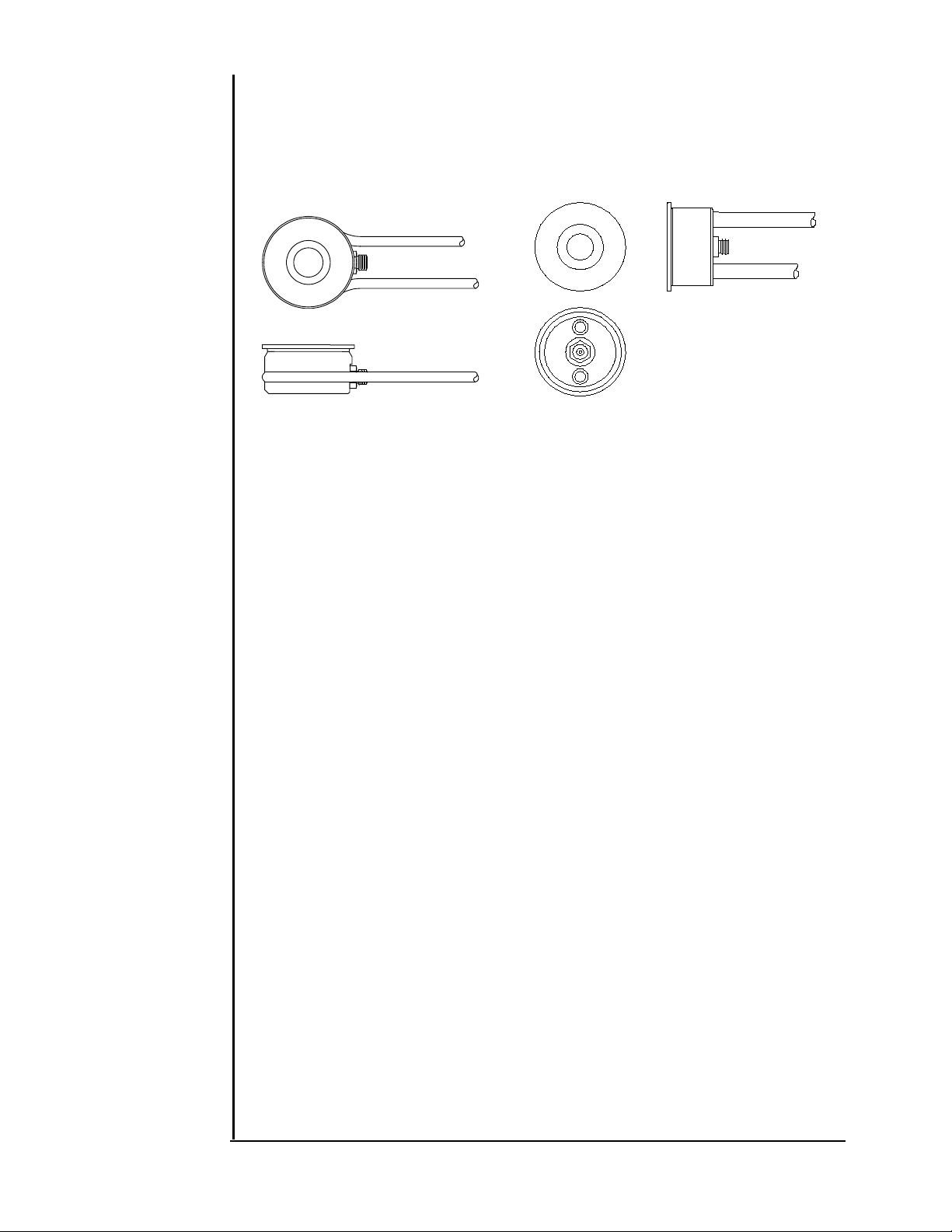
Figure 1.1: Standard Sensors. ................................................................................................. 1-4
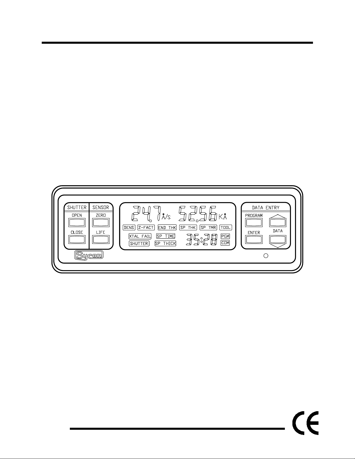
Figure 2.1: STM-100 / MF Front Panel. .................................................................................. 2-1
Figure 2.2: System Control Keys. ............................................................................................ 2-1
Figure 2.3: Data Entry And Programming Keys. ..................................................................... 2-2
Figure 2.4: LCD Data Areas. .................................................................................................... 2-4
Figure 2.5: LCD Variable Parameter Legends. ........................................................................ 2-4
Figure 2.6: Film Number Parameter. ....................................................................................... 2-4
Figure 2.7: Density Parameter. ................................................................................................ 2-5
Figure 2.8: Z-Factor Parameter. .............................................................................................. 2-5
Figure 2.9: End Thickness Parameter. .................................................................................... 2-6
Figure 2.10: Set Point Thickness Parameter. .......................................................................... 2-7
Figure 2.11: Set Point Timer Parameter. ................................................................................. 2-7
Figure 2.12: Tooling Parameter. .............................................................................................. 2-8
Figure 2.13: Configuration Switch Settings. ............................................................................. 2-9
Figure 3.1: Rear Panel. ............................................................................................................ 3-1
Figure 3.2: Recommended Grounding Procedure. .................................................................. 3-2
Figure 3.3: Recorder Output Plug. ........................................................................................... 3-5
Figure 3.4: Example of Thickness Mode Recorder Output. ..................................................... 3-6
Figure 3.5: Example of Rate Mode Recorder Output. ............................................................. 3-6
Figure 3.6: Cable Connections From STM to MSDos Computers. ......................................... 3-7
Figure 3.7: Typical System. ..................................................................................................... 3-8
Figure 3.8: Head Mounting Dimensions................................................................................... 3-9
Figure 4.1: Typical Tooling Factors. ......................................................................................... 4-3
Figure 5.1: Cable Connection From STM-100 / MF to IBM-AT. .............................................. 5-1
Figure 5.2: Connections for STM-100 / MF to PC Compatible Computers. ........................... 5-2
Figure 5.3: BASIC Driver Routine. ........................................................................................... 5-4
Figure 5.4: HP-85 IEEE-488 BASIC Driver Program. .............................................................. 5-7
Figure 6.1: Sensor and Feed Through Connections. ............................................................... 6-3
Figure 6.2: Test Oscillator OSC-100A. .................................................................................... 6-4
Figure 6.3: SM75, MicroDot
Figure C.1: SHMX-4 Front Panel ............................................................................................. C-1
Figure C.2: Firmware ROM Label ............................................................................................ C-2
Connector. ................................................................................ 6-4
Figure C.3: SHMX-4 Back Panel ............................................................................................. C-2
Figure C.4: SHMX-4 to STM-100 Control Cable ...................................................................... C-3
List of Figures Page viii
Page 11

List of Tables
Table 2.1: Baud Rate Switch Settings .......................................................2-10
Table 2.2: Configuration Switch Address Sett ings ....................................2-11
Table 4.1: Common Material Reference Table ........................................... 4-4
Table 4.1: Common Material Reference Table, Cont inued ......................... 4-5
Table 4.1: Common Material Reference Table, Cont inued ......................... 4-6
Table 5.1: Baud Rate Configuration Table. ................................................ 5-2
Table 5.2: Communication Command Summary........................................ 5-8
Page ix List of Tables
Page 12

SECTION 1
General Information
Page 13

Page 14

GENERAL INFORMATION
SECTION 1.1
SECTION 1.2
INTRODUCTION
The STM-100 / MF from Sycon Instruments, Inc. represents a new class
of thin film monitor. I t uses the time-proven 6 MHz oscillating quartz crystal as
the sensor device. The STM-100 / MF is constructed with advanced LSI and
microprocessor technology. This enables the dir ec t solut ion of the complex
mathematical equation associated with the f r equency shift versus mass
loading characteristics of the quartz crystal sensor. Its computational power
allows the measurement of the material accum ulat ed on t he s ensor c r ystal t o
be accurately converted to film thickness using the exact equation;
inaccuracies due to approximations and limited ranges of m aterial constants
do not contribute to thickness and r at e er r or s . A hig h frequency period
measurement clock (over 70 MHz) enables the STM-100 / MF to make and
display 4 measurements/second with one-tenth Angstr om r ate resolution. The
STM-100 / MF is equipped with 4 setpoint relays, 4 remote inputs, a comput er
interface (RS-232) supporting 2 protocols including SECS-II, and a high
resolution analog recorder output. A r ack mount for half-rac k mounting is also
standard. If desired, t he front panel LCD can be configured, by rear panel
switch setting, to display the freq uency of the sensing crystal instead of
computed rate and thickness. ST M-100 / MF 's manufactured and shipped
after October 1990 have the additional capability of storing film parameter for
nine film or processes. Earlier STM's can be factory upgraded to include this
feature. An extra-cost opt ion is a second com puter interface. This f actory
installed upgrade can be either IEEE-488 or BIT BUS.
UNPACKING
The STM-100 / MF comes with a power cord, and connectors for the RS232 interface, the I/O int er face and analog output. If t he O SC-100 or crystals
were ordered at the same time, they will also be included. The unit is shipped
with the rack mount attached, which may be removed for t able t op oper at ion.
To complete a system installation a sensing head and a vacuum to air
feedthrough are req uir ed. Schematic drawings and a MSDOS Format diskette
of demonstration sof t ware are included with this manual. Refer to Appendix A
for a detailed description of the included software. The unit comes set for the
line voltage as ordered. If you need to change it , r efer to Section 3.2. Make
sure that you install the correct fus es when changing line voltage. If it is ever
necessary to return the unit to Sycon, f or any reason, call and obt ain an Retur n
Authorization (RA) num ber before returning the unit.
Page 1 - 1 GENERAL INFORMATION
Page 15

SECTION 1.3
STM-100 / MF SPECIFICATIONS
DISPLAY TYPE ........................................ 7 DIGIT LCD
THICKNESS DISPLAY RANGE ................ 0 to 999.9 kÅ
RESOLUTION .................................. 1 Å autoranged
# DIGITS .......................................... 4
RATE DISPLAY RANGE........................... 0.0 to 999 Å/S
RESOLUTION .................................. 0.1 Å/S autoranged
# DIGITS .......................................... 3
MEASUREMENT PERIOD........................ 0.25 SEC
SENSOR TYPE ................................ Quartz Crystal Microbalance
FREQUENCY ................................... 6 MHz Plano Convex A/T Cut
MAX. FREQ. SHIFT ......................... 1 MHz
FILM PARAMETER .................................. 9 MATERI AL S
VARIABLES .............................................. 7
FILM # .............................................. 1 t o 9
MATERIAL. DENSITY ...................... 0.500 t o 99. 99 gm/cc
MATERIAL. Z FACTOR.................... 0.100 to 9.999
SYS. TOOLING ................................ 10.0 to 399 %
SHUT TER CLOSURE ...................... 0.000 to 9999 kÅ
T HI CKNESS SETPOINT .................. 0.000 to 9999 kÅ
T I MER SETPOINT ........................... 00:00 to 99:59 M:S
I/O CONNECTION .................................... 15 PIN D MALE
HARDWARE O UTPUTS ........................... 4, SPST 2.5A RELAYS
- Shutter Relay (Pins 5,6)
- Thickness Setpoint (Pins 7,8)
- Sensor Failure (Pins 1,2)
- Timer Setpoint (Pins 3,4)
HARDWARE I NPUTS ............................... 4 TTL COMP., ACTIVE LOW
- Open Shutter (Pin 12)
- Close Shutter (Pin 11)
- Zero Thickness (Pin 10)
- Zero Timer (Pin 9)
Note: Pins 13,14,15 are GND.
ANALOG RECORDER ............................. + 10V F.S. RATE OR THICKNESS
- 2 mA max Load,
- 11 BIT Resolution
CONNECTION ................................. Miniature Stereo Jack
STD. COMMUNICATIONS I/O .................. RS-232, DUAL PROTOCOL
- 4 BAUD RATES
- 300,1200,2400,9600
CONNECTION ................................. - 9 PIN "D" FEMALE
GENERAL INFORMATION Page 1 - 2
Page 16

OPTIONAL COMMUNICATIONS I/O
1) ...................................................... IEEE-488 T/L
CONNECTION ................................. - 24 PIN TYPE 57 FEMALE
2) ...................................................... BITBUS Slave Node
CONNECTION ................................. - 2 TWINAX BNC's
DISPLAY FUNCTIONS
1) ..................................................... DATA/FILM #
2) ..................................................... THICKNESS / RATE
3) ..................................................... CRYSTAL % USAGE / TIMER
4) ..................................................... SENSOR FREQUENCY
DISPLAY ANNUNCIATORS ..................... STATUS
RELAY ............................................. ON/OFF EACH RELAY
PARAMETER ID .............................. EACH VARIABLE
MODE ID .......................................... PROGRAM / OPERATE
ACTIVITY ......................................... COMMUNICATIO NS INTERFACE
KEYBOARD FUNCTIONS ........................ 8 KEYS
TYPE ................................................ Individual Buttons
FUNCTIONS .................................... - Shutter Open
- Shutter Close
- Zero Thickness & Time
- Set Program Mode On / Of f
- Increase Value
- Decrease Value
- Enter Data
- Crystal Status
USER OPTION SWITCHES ..................... Rear Panel
- Baud Rate Selection
- Serial Protocol Selection
- Communications Address
- Parameter Lock
- Negative Limit Operation
- Frequency Meas. Mode
- Analog Recorder Function
POW ER REQUIREMENTS ....................... 120/240V,+5%-
......................................................... 20%,50/60Hz,10VA
CONNECTOR .................................. IEC Standard
POWER SWITCH ............................ Rear Panel Mounted
T EMPERATURE RANG E ................. 0o C to 50oC Operating
-15oC to 65oC Storage
SIZE / WEIGHT ........................................ 2.5"H, 7.25"W, 10"D 4lbs
(RACK MOUNTED) .................................. 3.5"H, 8.0"W, 10"D ;
SHIP WEIGHT .......................................... 8lbs
Page 1 - 3 GENERAL INFORMATION
Page 17
SECTION 1.4
OPERATION
WATER
ELECTRICAL
MATERIALS (IN VAC)
SECTION 1.5
SENSOR SPECIFICATIONS
Low Profile P/N 500-042 RIGHT ANGLE P/N 5 00 -088
Figure 1.1: Standard Sensors.
Low Profile and Right Angle sensors, See Appendix B for dimensions and
more detailed drawings of these and other sensor pac kages.
Maximum Temperature ............................. 175° C
Water Line and Coax Lengt h ................... 30 inches
Sensor Mounting ...................................... Rear of Body, 4-40 Tapped Holes
FEEDTHROUGH INSTALLATION
Connections .................................... Two Required
Type ................................................ 1/8 inch O.D. Stainless Tubing
Flow Rate ......................................... 0.2 to 0.3 gal/min
Water Temp ..................................... 50° C max.
Connections .................................... One Coaxial Line
Type ................................................ Microdot Miniature S-50
Body and Water Lines .................... 304 Stainless
Insulators ........................................ Alumina
Coax Insulator ................................. Teflon
Coax Conductor and Shields ........... Copper/Silver
Braze Material ................................. High Vac Ni/CR/Cu Alloy
Crystal ............................................. Quartz with Gold Electrodes
SENSOR SPARE PARTS
Description SYCON Part Number
Sensor Body (Standar d) .................. 550-219
Snap Spring ..................................... 024-002
Sensor Cap ...................................... 550-218
30 inch In-Vacuum Coax Cable ....... 500-024
10 inch In-Vacuum Coax Cable ....... 500-023
Crystals (box of 10) ......................... 500-117
GENERAL INFORMATION Page 1 - 4
Page 18

STM-100 / MF PARTS & ACCESSORIES
SECTION 1.6
MONITOR
FEEDTHROUGHS
SENSORS
OPTIONS
ACCESSORIES
SENSOR CRYSTALS
ASSEMBLY PART NUMBER
STM-100 / MF (Multi Film) ................ 500-104
POWER CORD (12 0 VAC).............. 600-004
FUSES (1/4 A Slow Blow for 120VAC) ...... 356-005
FUSES (1/8 A Slow Blow for 240VAC) ...... 356-007
RECORDE R PLUG ......................... 404-007
I/O 15 PIN CONNECTOR ................ 404-008
RS-23 2 9 PIN CONNECTOR .......... 404-009
MANUAL ......................................... 518-000
CONNECTOR KIT ............................ 514-001
19" Rack Mount (Single) ................... 014-008
19" Rack Mount (Dual) ..................... 014-009
1" BOLT STANDARD ...................... 500-016
2 3/4" ConFlat STANDARD ............. 500-017
LOW PROFILE ................................. 500-042
RIGHT ANGLE ................................ 500-088
IEEE-488 BUS INTERFACE ............ 500-021
BITBUS INTERFACE ...................... 500-022
30" I N-VACUUM COAX CABLE ...... 500-024
10" I N-VACUUM COAX CABLE ...... 500-023
10' OSC TO STM CABLE ................ 500-026
30' OSC TO STM CABLE ................ 500-027
6" OSC TO FEED THRU COAX ....... 500-025
BOX O F 10 ...................................... 500-117
Page 1 - 5 GENERAL INFORMATION
Page 19

SECTION 2
Operation and Programming
Page 20

Page 21
STM - 100 / MF
THICKNESS / RATE MONITOR
instruments
SHUTTER
SENSOR
OPEN
ZERO
CLOSE
LIFE
DENS
Z-FACT END THK
XTAL FAIL
SHUTTER
SP TIME
SP THICK
SP THK SP TMR TOOL
PGM
COM
DATA ENTRY
PROGRAM
ENTER
DATA
OPEN
CLOSE
SENSORSHUTTER
ZERO
LIFE
SECTION 2.1
SECTION 2.2
OPEN
CLOSE
SHUTTER
Shutter Keys
OPERATION AND PROGRAMMING
KEYBOARD DESCRIPTION
The STM-100 / MF keyboard is divided into two separate functional
groups. The keys to the left of the LCD display are system control keys and
the keys to the right of the display are data entry and programming keys. All
keys are sensed when depressed and must be released to cause further
action. The exceptions to this rule are the (LI FE) and ( ARROW) keys. T hese
keys will cause continuous action if held depressed. An audible beep will
accompany each key activation. The beeper may be disabled if desired. See
Section 2.7.
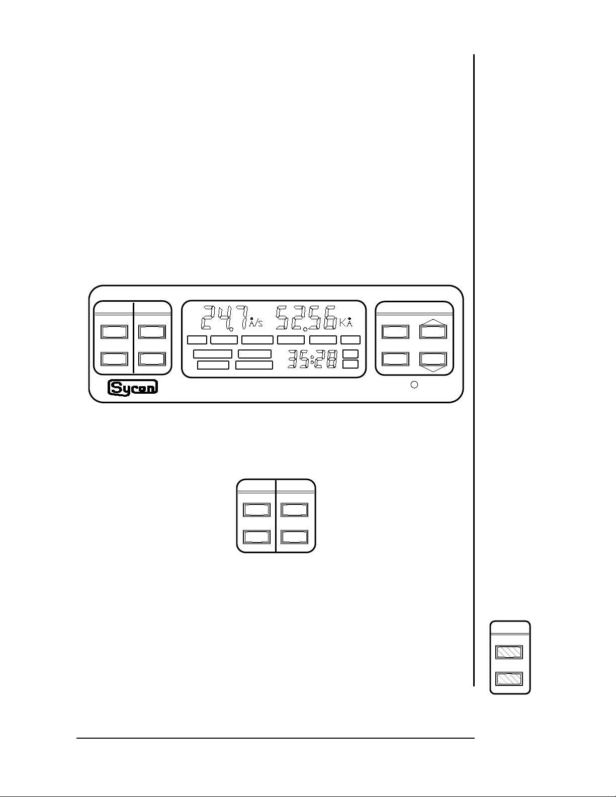
Figure 2.1: STM-100 / MF Front Panel.
SYSTEM CONTROL KEY GROUP
Figure 2.2: System Control Keys.
SHUTTER OPEN
Activating the SHUTTER OPEN key will cause the internal shutter relay
contacts to close. This relay is typically used to control a deposition system
source shutter. The LCD display (SHUTTER) leg end will be visible when the
shutter relay is active. This key is active at all times and states (Program and
Normal) of the STM-100 / MF. A remote input duplicating this key function is
also provided.
Page 2 - 1 OPERATION AND PROG RAMMING
Page 22
SHUTTER CLOSE
DATA
ENTER
PROGRAM
DATA ENTRY
ZERO Key
ZERO
Crystal Life Key
LIFE
SECTION 2.3
Program Key
PROGRAM
The SHUT TER CLOSE key provides the reverse function of the
SHUTTER OPEN key. This key is active at all times and states of the
STM-100 / MF. A remote input duplicating this k ey f unc t ion is also provided.
ZERO
The ZERO key provides two functions, "THICKNESS ZERO" and " TIMER
ZERO". Activating the key will cause any accumulated reading in the
thickness display to be set to zero, thus providing a new accumulation
reference point. It will also reset the elapsed t imer and display to t he set point
value contained in the program m emory. Any setpoint relays that may have
been closed at the time of the "ZERO" key operation will be reset to the open
state. This key is inactive in the PROGRAM mode. Remote inputs providing
separate operation of the THI CKNESS ZERO and T I MER ZERO operations
are also provided. Note that during a Crystal Fail condition, the Zer o key does
not function.
LIFE
Activating the CRYSTAL LIFE key will provide the user with a measure of
remaining possible sensor crystal life. T his information is expressed in percent
with 100% representing a new sensor crystal and 0% indicating a fully loaded
sensor crystal (1MHz frequency shift). This information is presented where
rate information is normally shown. This data should serve as an indicator for
the need to change the sensor crystal. T he frequency of the sensor crystal t o
the nearest kilohertz is also presented. T his information is shown where
accumulated thickness data is normally displayed. A new sensor crystal
should indicate close to 99% life and a freq uency near 5. 950 MHz. This key
function is inactive in the PROGRAM mode. Activating this key during a
CRYSTAL FAIL condition may result in a blank data display. The LIFE display
is active as long as the LIFE key is held depressed.
DATA ENTRY AND PROGRAMMING GROUP
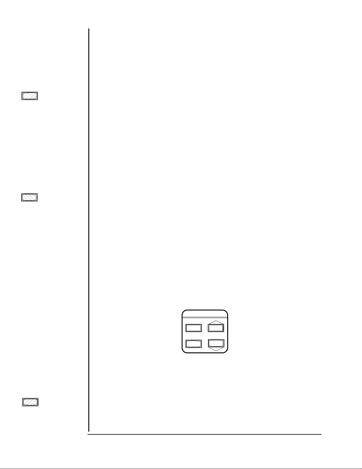
Figure 2.3: Data Entry And Programming Keys.
PROGRAM
Activation of the PROGRAM key places the instrument in a mode wherein
the internal parameter variables may be viewed or modified. Data view
operation is always available whereas, data modification may be inhibited by a
user option switch on the rear panel. If the instrument is in the PROGRAM
mode, depressing the PROGRAM key will return the unit to the norm al display
mode. Six variable parameters, for each of nine films of the STM-100 / MF
OPERATION AND PROG RAMMING Page 2 - 2
Page 23

may be programmed by the user. Two of t hes e m at erial constants are needed
Enter Key
ENTER
Arrow Keys
DATA
SECTION 2.4
LCD Data Displays
to provide correct thickness and rate information for a particular film material
and one is a constant used to correct f or system sensor and substrate
geometry variations. Three setpoint variables ar e pr ovided to act ivate relay
events. Two of these are related to thickness and one to elapsed time. These
variables and their meanings are discussed in detail in Section 2.4.
ENTER
The ENTER key has two functions. It is used (1) to sequence through
the six parameter variables, one parameter f or eac h pr ess of the ENTER key,
and (2) to place modified variable data into the non-volatile storage memory of
the instrument. This data will be retained until modif ied by the user even with
no power to the instrument. A legend on the LCD display will indicate which
variable parameter data is being displayed. Any modifications to parameter
data occur in the display memory only, and will cause the associated
parameter legend to f lash. The flashing legend indicates that a param et er
change has been made but has not yet been saved in memory. To stor e the
data in memory the ENTER key must be pressed. Exiting t he PRO G RAM
mode (via the PROGRAM key) while a parameter legend is flashing does not
cause the modified data to be saved. Previously saved parameter data will be
retained. The ENTER key only functions in the PROGRAM mode.
ARROW KEYS
The ARROW keys are used to select t he ac t ive f ilm and to increment or
decrement the displayed parameter variable data in order to achieve the
desired value. The rate of incremental change will increase as the key is held
depressed. This will speed up parameter changes covering a large dynamic
data range. Letting up on the key and then resuming key depression will reset
the rate of change to t he slowest rat e and it will again increase with time as t he
key remains depressed.
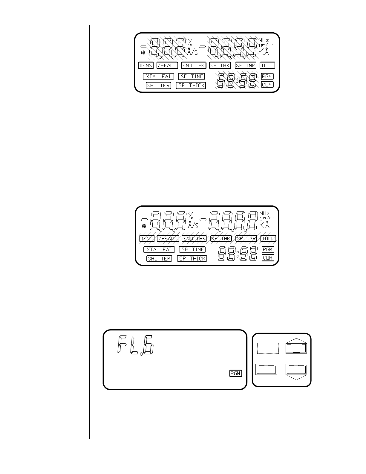
FILM PARAMETERS
The STM-100 / MF utilizes a high contrast liquid crystal display for the
viewing device. All measurement data, instrument status, and pr ogram
variable operations are viewable on the display. A three or four digit parameter
display and a four digit time display (min:sec) are used t o display the dynamic
data.
Page 2 - 3 OPERATION AND PROG RAMMING
Page 24
PROGRAM
ENTER
DATA
Film Number Parameter
Figure 2.4: LCD Data Areas.
The STM-100 / MF incorporates six programmable parameter variables
for each of nine films pr ogrammable by the user. Three variables are used by
the thickness equation and are relat ed t o m at erial physical constants and
system geometry (Density, Z-Factor, and Tooling). The three remaining
parameters are used as setpoint values to activate t he internal relays on the
I/O connector.
Each variable has a specif ic LCD legend as soc iated with it. These
legends are only active in the PROGRAM mode and only one will be on at a
time. Each parameter is discussed in more det ail below.
Figure 2.5: LCD Variable Parameter Legends.
Af ter entering the program m ode by pushing t he Pr ogram Button the
current film number is displayed in the upper lef t hand c or ner of the LCD
display. (FL.n, n is 1 through 9). Ref er to Figure 2.6.
Figure 2.6: Film Number Parameter.
At this point t he c ur r ent film's parameters may be reviewed or changed or
a new current film selected. To select a new current film the film number is
OPERATION AND PROG RAMMING Page 2 - 4
Page 25
increased or decreased by using the up and down arrow keys. Pushing the
Density Parameter
enter button selects the film num ber shown to be the c ur r ent film and displays
the first parameter ( densit y) of that film. Each of t he film parameters can now
be reviewed or changed by using the DATA keys and / or the ENTER key.
WARNING
When leaving the Program Mode, the last Selected
FILM is the current active FILM.
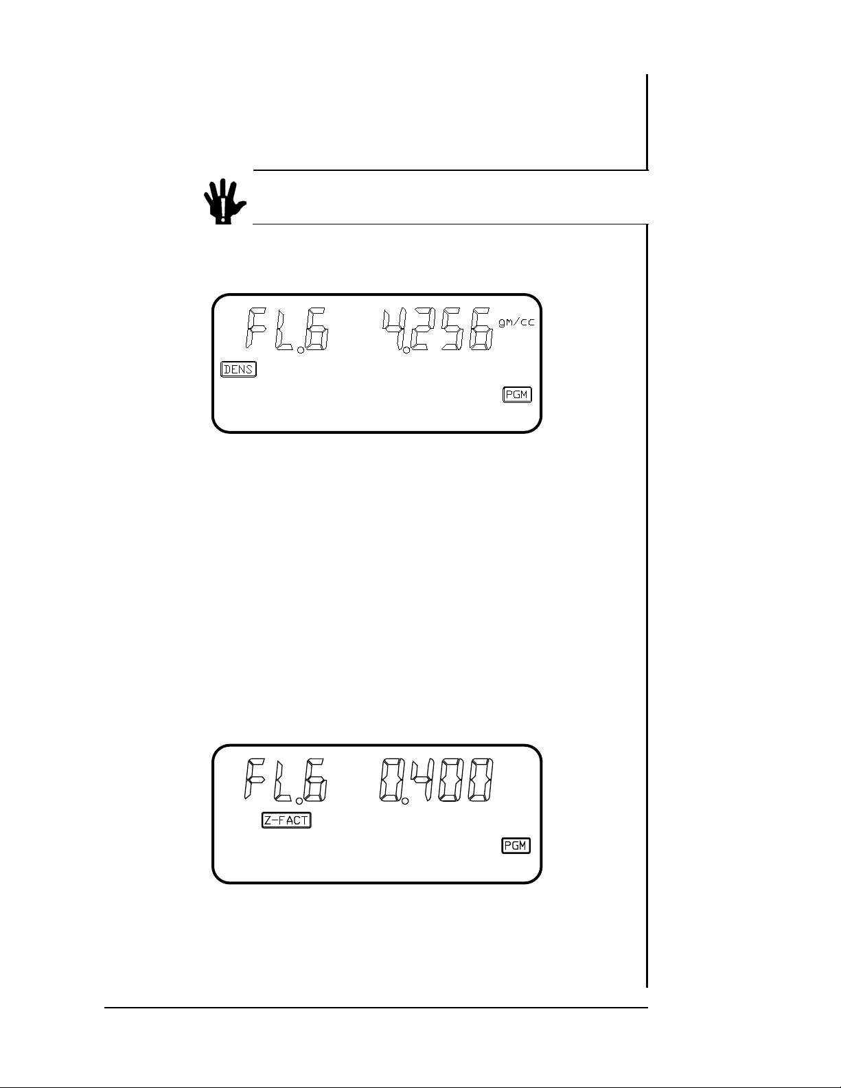
DENSITY
Figure 2.7: Density Parameter.
LEGEND DENS
RANGE 0. 500 to 99.99
UNITS gm/cc
The DENSITY parameter refers to t he m easured material density in
gm/cc. This constant is nor m ally the bulk m at er ial value but is somet im es
different due to deposition and film growth conditions. This value is utilized in
the thickness equation to convert m easured mass to a thickness value. See
Table 4.1 for an extensive value list. See Section 4.2 for calibr at ion
information.
LEGEND Z-FACT
RANGE 0. 100 to 9.999
UNITS NONE
Page 2 - 5 OPERATION AND PROG RAMMING
Z-FACTOR
Figure 2.8: Z-Factor Parameter.
Page 26
Z-Factor Parameter
End Thickness
The Z-Factor parameter refers t o t he elastic properties of the measured
material. This value is utilized in the thickness equation to m at c h t he
acoustical properties of the film being measured to the acoustic properties of
the base quartz material of t he sensor c r ystal. This correction is necessary to
insure accurate measurements when sensor crystal shifts of greater than 15%
are realized. See Table 4.1 for an extensive material value list. See Section
4.2 for calibration inform at ion.
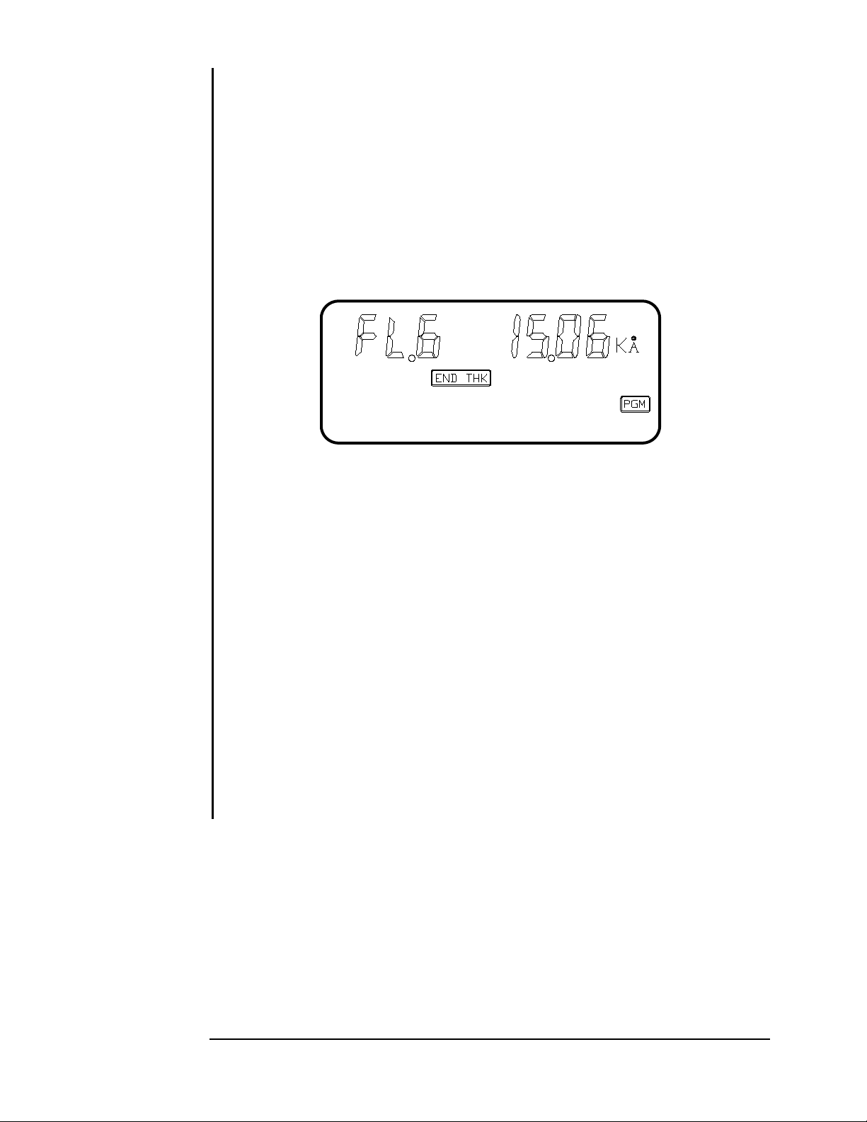
END THICKNESS
Figure 2.9: End Thickness Param et er .
LEGEND END THK
RANGE 0 to 9999
UNITS KILO ANGSTROMS (1 Angstrom = 10
-10
meters)
The END T HI CKNESS paramet er is used to provide a trigger setpoint for
the STM-100 / MF Shutter Relay contacts. If t he s hut t er relay contacts are
closed by operating the front panel shutt er c losed but t on or by rem ot e input .
These contacts will return to the open state when the thickness display value
becomes equal to or exceeds the END THICKNESS SETPOINT value. T he
STM-100 / MF Shutter Relay contacts are normally used to automatically
control a deposition system source shutter. This is a trigger event and will
only effect shutter st at us at t he time the event occurs. If the shut t er r elay
contacts were already open at the time of the event the event will be ignored.
A setpoint value of 0.000 kÅ causes the setpoint function to be ignored.
OPERATION AND PROG RAMMING Page 2 - 6
Page 27
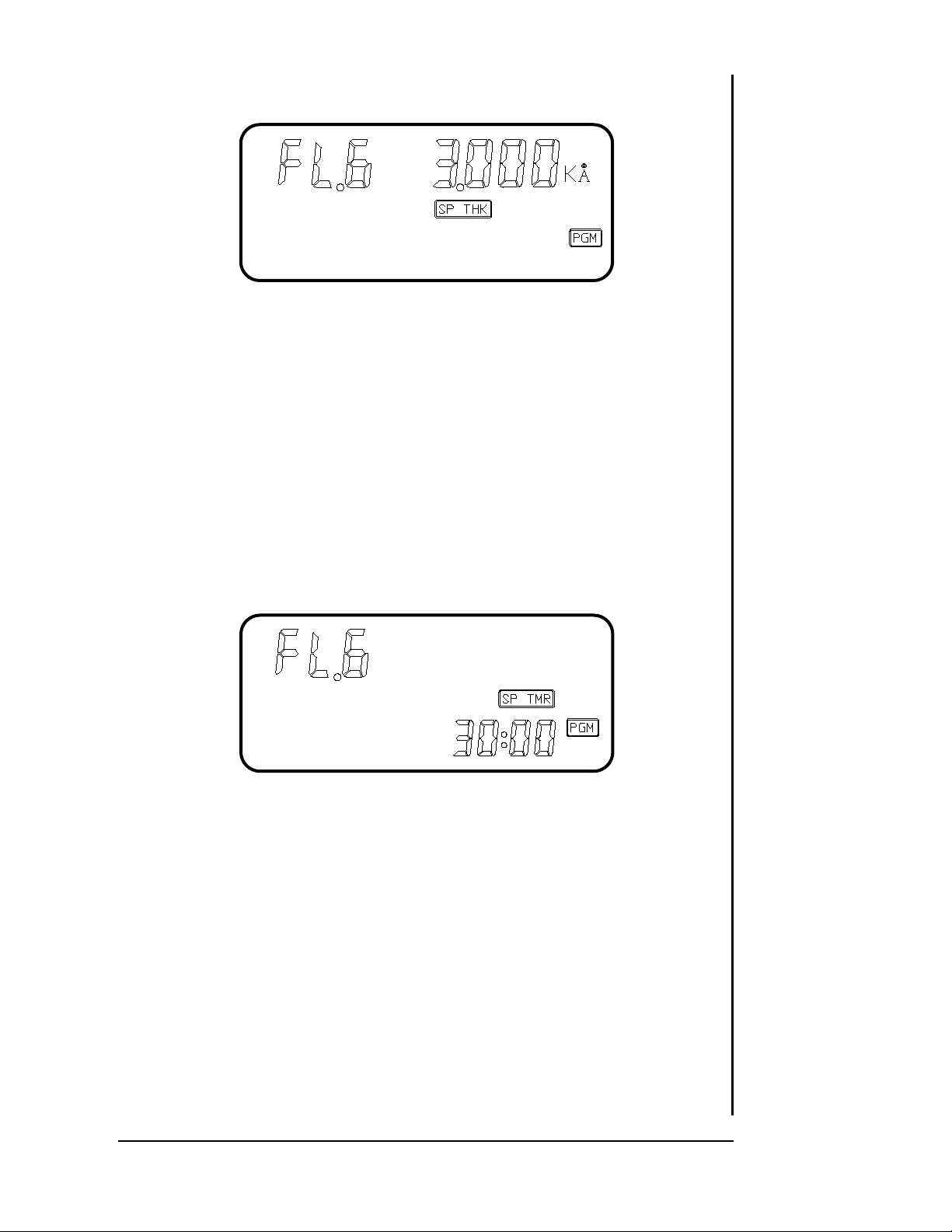
SETPOINT THICKNESS
Setpoint Thickness Parameter
Setpoint Timer
Figure 2.10: Set Point Thicknes s Par am et er.
LEGEND SP THK
RANGE 0 to 9999
UNITS KILO ANGSTROMS
The SETPOINT THICKNESS parameter is used to provide a comparison
point for the STM-100 / MF Thickness Set point Relay. T his set of relay
contacts will be closed whenever the thickness display equals or exceeds the
setpoint value. A setpoint value of 0.000 kÅ causes the t hickness setpoint
function to be ignored.
SETPOINT TIMER
Figure 2.11: Set Point Timer Parameter.
LEGEND SP TMR
RANGE 00:00 to 99:59
UNITS MIN:SEC
The SETPOINT TIMER parameter is used to provide a comparison point
for the STM-100 / MF Timer Setpoint Relay. The int er nal STM-100 / MF timer
is pre-set with the setpoint value whenever the front panel ZERO k ey, or a
remote ZERO TIMER input, is activated. The Tim er Relay contact s ar e
opened at this time and the timer display begins counting downward toward
zero. When the timer display reaches zero the relay contacts are closed and
the display timer begins counting in an upwards fashion. A setpoint value of
00:00 will cause the timer setpoint function to be ig nor ed.
Page 2 - 7 OPERATION AND PROG RAMMING
Page 28

TOOLING
Tooling Factor Parameter
SECTION 2.5
Figure 2.12: Tooling Paramet er .
LEGEND TOOL
RANGE 10.0 to 399
UNITS PERCENT
The TOOLING parameter is used as a corr ection factor to compensate
for geometric position differences between the location of the sensor and the
target substrate. Cor r ec t ion is r equired both the substrate and sensor see the
material source in an identical manner, unless for this case, the Tooling
Parameter is set to 100%. Generally, if the sensor is farther f r om the source
than the substrate, the tooling will be set to >100%. If the sensor is closer to
the source, the tooling will be set to < 100%. See Section 4. 2 for calibration
information.
USER CONFIGURATION SWITCHES
On t he r ear panel of the STM-100 / MF a twelve selection configuration
switch is located. The settings of this switch allow the user to select various
system operational modes. All communications related variables are also set
here. Switches 1 thru 4 may be changed at any time and will have immediate
effect. Switches 5 thru 12 ar e only read at t he time of power turn on.
OPERATION AND PROG RAMMING Page 2 - 8
Page 29
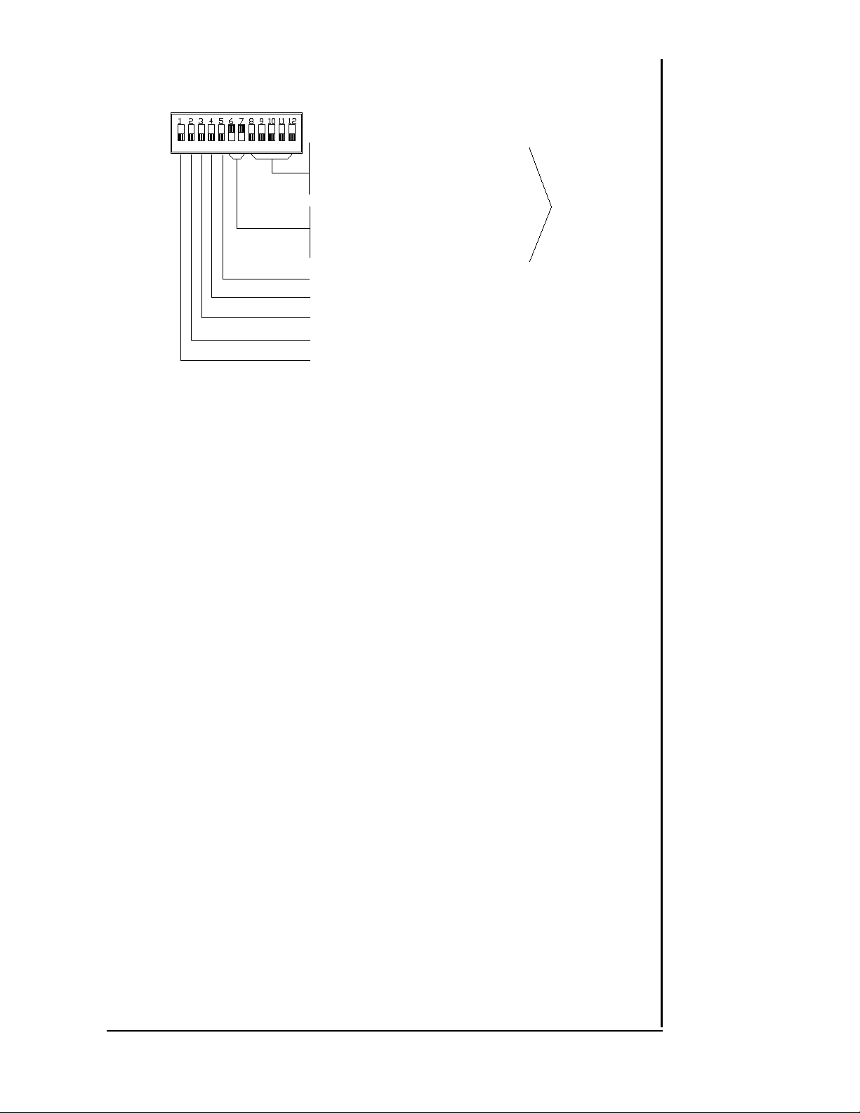
CONFIGURATION
SWITCH
BINARY DEVICE ADDRESS
SW8=MS BIT SW12=LS BIT
SW 8 SW9 SW10 SW11 SW12
OFF OFF OFF OFF OFF = 0
OFF OFF OFF ON OFF = 0
ON OFF ON OFF ON = 0
SERIAL BAUD RATE
SW 6 SW7
OFF OFF = 300
OFF ON = 1200
ON OFF = 2400
ON ON = 9600
PROTOCOL ON = SEMI OFF = SYCON
NEGATIVE RATES ON = ENABLE OFF = DISABLE
FREQUENCY MODE ON = ENABLE OFF = DISABLE
ANALOG OUTPUT ON = THICK OFF = RATE
PARAMETER LO CK ON = LOCK OFF = UNLOCK
see Note:
NOTE: Sw itch settings involvi ng c omm unications functions are sensed at power up onl y.
Configuration
Figure 2.13: Configuration Switch Settings.
SWITCH FUNCTION DEFINITIONS
SW1 - PARAMETER LOCK
When on, st or ed par am eter data cannot be modified via the front
panel. This switch is sensed at all times.
SW2 - RECORDER FUNCTION
When on, the analog output will provide thickness information.
Rate information is presented in the off state. This switch is
sensed at all times. See Section 3.6.
SW3 - FREQUENCY MODE
When on, the unit will display seven digits of sensor frequency to
a resolution of one Hertz. All other instrument functions remain
normal. This switch is active at all times.
SW4 - NEGATIVE LIMITS
When on, both thickness setpoints and their associated relays will
activate on negative thickness data only. This switch is sensed at
all times.
SW5 - SERIAL COMMUNICATIONS FORMAT
When on, the RS-232 serial communications channel will respond
SW6 & SW7 - BAUD RATE SELECT ION
These two switch settings in combination select one of four baud
Page 2 - 9 OPERATION AND PROG RAMMING
to SEMI STANDARD SECS-II form at t ed c om m ands. Sycon
formatted commands ar e valid f or the off state. This switch is
sensed only at power-up.
rates for the RS-232 serial comm unicat ions channel. These
switches are sensed only during power-up.
Page 30

SW6 SW7 BAUD
OFF OFF 300
OFF ON 1200
ON OFF 2400
ON ON 9600
Table 2.1: Baud Rate Switch Settings
SW8, SW9, SW10, SW11, SW12 DEVICE ADDRESS SELECTION
These switches in combination select the device address for t he
instrument when operating with the SECS RS-232 protocol or with
either the IEEE-488 or BITBUS communications opt ion car ds.
These options allow multiple devices to operate on a single bus,
and only the individual addressing prevents response conflicts.
Switch coding is in binary 1 of 32 format with SW8 the MSB and
SW12 the LSB. T hes e switches are s ensed only during powerup. See Table 2.2 for a list of addresses.
OPERATION AND PROG RAMMING Page 2 - 10
Page 31

Switch Setting Address
SECTION 2.6
Enabling the Test Mode
SW8 SW9 SW10 SW11 SW12 IEEE BITBUS / SECS II
off off off off off 0 32 / 0
off off off off on 1 1
off off off on off 2 2
off off off on on 3 3
off off on off off 4 4
off off on off on 5 5
off off on on off 6 6
off off on on on 7 7
off on off off off 8 8
off on off off on 9 9
off on off on off 10 10
off on off on on 11 11
off on on off off 12 12
off on on off on 13 13
off on on on off 14 14
off on on on on 15 15
on off off off off 16 16
on off off off on 17 17
on off off on off 18 18
on off off on on 19 19
on off on off off 20 20
on off on off on 21 21
on off on on off 22 22
on off on on on 23 23
on on off off off 24 24
on on off off on 25 25
on on off on on 27 27
on on on off off 28 28
on on on off on 29 29
on on on on off 30 30
on on on on on 0 31
The STM-100 / MF incorporates a test and deposition simulation mode to
aid in trouble shooting and demonstrating t he instrument. This mode simulates
a deposition rate of 16 Angstrom s per second with a Density and Z-Fact or of 1
and Tooling of 100%. The t est mode may be activated only in the nonprogram mode. Holding the UP ARROW key down while activating the
SHUTTER CLOSE key will turn the test mode on. The Å/S and KÅ legends
will blink continuously to indicate the test function. Once in the t es t m ode t he
Page 2 - 11 OPERATION AND PROGRAMMING
Table 2.2: Configuration Switch Address Sett ings
TEST MODE
Page 32

shutter open and close buttons control the sim ulat ed deposit ion. The test
SECTION 2.7
Disabling the Beeper
mode may be turned off by holding the UP ARROW key depressed and then
activating the SHUTTER OPEN key. Turning the unit off and back on also
clears the test mode.
BEEPER
The beeper will give a short audible tone when any key is depressed or
the unit power switch is turned on. The keyboard beeper may be disabled if
desired by holding the DOWN ARROW key and activating the SHUTTER
CLOSE key while not in the PROGRAM mode. The same procedure and
activating the SHUTTER OPEN key will turn the beeper on.
The beeper will always be enabled after power is applied to the unit.
OPERATION AND PROG RAMMING Page 2 - 12
Page 33

SECTION 3
Installation
Page 34

Page 35

INSTALLATION
DAMAGE TO THE UNIT .
DAMAGE TO THE UNIT .
SECTION 3.1
SECTION 3.2
Line Power Warning
Line Voltages
POWER
Electrical Connections and Descriptions
All electrical connections to the STM-100 / MF are made at the rear panel of the
instrument. Care should be exercised in routing all cables as far as practically
possible from any other cables or wires that may be generat ing noise. These may
include other line voltage cables, wires to heaters that are SCR-cont r olled, and
wires or cables that may conduct high transient curr ent s during arc over of an Ebeam type supply.
Figure 3.1: Rear Panel.
WARNING
REPLACE BROKEN OR BLOWN FUSES ONLY W ITH
The STM-100 / MF may be configured to operate on either 110V or 220V
nominal line voltage. Units are factory-shipped conf igured for 110V operation
unless otherwise ordered. The setting may be verif ied by noting t he line voltage
value visible in the small window of the power and fuse module. To change the
configuration firs t r em ove the power cord, then release the latch in the center of
the module and remove the insert holding the f uses . The insert contains two
fuses, the system fus e and a spar e. Remove both fuses, then pull the two-prong
fuse holder out of the latching insert. Rotate the fuse holder and replace it int o t he
latching insert such that the proper line voltage is visible in the window. The
reading will be either 110 or 220. Place the proper fuse into t he m et al clips ( 1/ 4
amp SB for 110V operation and 1/8 amp SB for 220V operation), place the spare
fuse into the spare fuse ar ea and r eplace the latching insert back into the power
module. Make sure the latch snaps are closed. Replace the power cord with the
OPERATING THE ST M-100 / MF AT 220V WHEN THE
UNIT IS CONFIGURED FOR 110V MAY CAUSE
TYPE 3AG SLOW BLOW OR EQUIVALENT WITH THE
RATINGS SPECIFIED. FAILURE TO DO SO MAY
RESULT IN UNSAFE OPERATION AND MAY CAUSE
Page 3 - 1 INSTALLATION
Page 36

proper type for the line voltage chosen. Proper power line cord should be used,
SECTION 3.3
Grounding
Connector Shielding
the 110V line cord should not be used for 220V operation.
GROUND
A gr ound pos t is pr ovided on the rear panel. This point should be connected
to the DEPOSITION SYSTEM GROUND with the shortest convenient lengt h of
heavy gauge wire. This connection is not required f or nor mal operation but will
make the unit less susceptible to transient noise. See Figure 3.2 for an example
of proper installation.
Figure 3.2: Recommended Grounding Pr oc edur e.
CONNECTOR INSTAL L ATION
In system s with a high noise environment, you need to be careful when
wiring up connectors. A little extra time spent her e can save you hours of
frustration later. Sycon provides mating connectors with each instrument. Extra
sets of mating connector s ar e available fr om Sycon as part number 514-001. For
best results, use a shielded multi-conductor c able. On the D-connectors, the
metal shells each come with a set of 4 gromm ets. Pick the grommet for the size
cable that you are using. Cut the outer insulation off of the cable so that it is
exposed to 3/4 of the grommet. Because the grommet is conductive, no additional
shield wiring is needed.
INSTALLATION Page 3 - 2
Page 37

I/O INTERFACE CONNECTION
SECTION 3.4
I/O Connector
RELAYS
INPUTS
Relay Outputs
Crystal Fail
Elapsed Timer
This c onnect or provides the user interface to the 4 sets of relay output
contacts as well as the 4 remote input command lines.
RELAY CONTACT RATINGS 2.5 AMPS - 120VAC MAX. - 120VA
Normally Open - SPST CONTACTS
I/O CONNECTOR DEFINITIONS
TYPE 15 Pin "D" Male
MATING CONNECTOR AMPHENOL 117-DA15S OR EQUIVALENT
FUNCTION PIN NUMBER
Crystal Fail 1, 2
Elapsed Timer 3, 4
Shutter Relay 5, 6
Thickness Setpoint 7, 8
Ground 13, 14, 15
Shutter Open 12
Shutter Close 11
Zero Thickness 10
Zero Timer 9
Ground 13, 14, 15
RELAY OUTPUTS
The STM-100 / MF is standard equipped with four SPST 2.5 AMP relays
rated to 120VAC and to 120VA. These contacts are normally open and become
active when their respective function is true. Continuous display of the st atus of
each relay is provided by legends on the LCD display. The available relay
functions are:
1. CRYSTAL FAIL - This r elay provides a contact closure whenever the sensor
crystal fails to operate properly or has exceeded its operating range.
The LCD legend for this relay status is ( X TAL FAIL). The legend will
also flash as a warning to the user.
2. ELAPSED TIMER - This relay provides a contact closure when the elapsed
timer has counted down to a value of zero from a set point value other
than zero. A setpoint value of zero disables this relay function. T he
display will continue to count in an upward fashion after a count of
zero is reached. The relay contacts will remain closed until the front
panel ZERO button or a remote TIMER ZERO event occurs, or a new
timer number is entered. The LCD legend for this relay is (SP TIME).
Page 3 - 3 INSTALLATION
Page 38

Shutter
Thickness Setpoint
Remote Inputs
Shutter Relays
Thickness Zero Input
Timer Zero Input
Remote Input Specifications
3. SHUTTER RELAY - This relay is intended to pr ovide contr ol of a deposition
system source shutter. The front panel and remote input OPEN and
CLOSE SHUTTER functions directly control this relay. T he c ont ac t s
are closed when the source shutter is intended to be open. The LCD
legend for this relay is (SHUTTER). The relay status is also
controlled by a END THICKNESS event. This event is controlled by
the END THICKNESS setpoint parameter. If the shutter is open at
the time of this event it will automatically close. The (SHUTT ER)
legend will turn off and the (END THICK) leg end will become visible,
indicating the shutter was closed by the END THICKNESS event.
4. THICKNESS SETPOINT - This relay provides a contact closure whenever the
accumulated thickness display value equals or exceeds the thickness
setpoint parameter value. This relay funct ion is disabled with a
parameter value of zero. The LCD legend for this relay is (SP
THICK).
REMOTE INPUTS
The STM-100 / MF is standard equipped with four remote input f unct ions.
These inputs are intended to be activated with a contact closure t o ground but may
also be controlled with TTL level signals. All remote inputs are leading edg e
detected and can thus remain activated indef initely. T o c ause t he event t o happen
again the input must be removed for a m inimum of 200 milliseconds and then can
be re-applied. The four available input commands are:
1. REMOTE SHUTTER OPEN - Funct ionally identical to front panel SHUTTER
OPEN button. Activating this input will close the contacts of the
SHUTTER RELAY.
2. REMOTE SHUTTER CLOSE - Func t ionally identical to front panel shutter close
button. Activating this input will open the contacts of t he SHUT TER
RELAY.
3. REMOTE THICKNESS ZERO - Sets t he acc um ulat ed t hickness display to
zero. Does not zero the elapsed time timer.
4. REMOTE TIMER ZERO - Re-initializes the elapsed time tim er . Does not zero
accumulated thickness.
SPECIFICATIONS
ACTIVATION ................................. Contact closure to gnd or TT L low
INPUT IMPEDANCE ..................... 2700 ohm s
OPE N CIRCUIT VOLTAGE ........... 3.5V typical, 5V max.
MAXIMUM ON VOLTAGE ............. 0.6 volts
MAXIMUM SINK CURRENT ......... 2 mA (1 TTL LOAD)
INSTALLATION Page 3 - 4
Page 39

Signal Ground
Shield
Signal
SECTION 3.5
Oscillator Connection
SECTION 3.6
Analog Output Specifications
SENSOR CONNECTION
CONNECTION TYPE -- BNC FEMALE
This c onnect ion is t he REMOTE SENSOR OSCILLATOR interface to the
STM-100 / MF. This connection is both the signal and power path to t he oscillator .
The supplied power is 5 volts at 50 mA. The input impedance is 50 ohms and the
signal level is 1 volt peak to peak. The DC voltage may be removed by
disconnecting internal STM-100 / MF jumper J1. T his m ay prove useful if a signal
source other than the Sycon oscillator is utilized. This connection should always
be made with coaxial cable. Type RG58 or RG59 is recommended. Cable lengths
up to 500 feet are acceptable. T hese c ables in 10 and 30 foot lengths are
available as standard parts from Sycon.
ANALOG RECORDER INTERFACE
This c onnect or provides an analog output voltage proportional to either
displayed RATE or THICKNESS as selected by the user option dip switches on the
rear panel of the STM-100 / MF. If SW2 of the user configuration dip switch is set
OFF the analog output will report RATE inform at ion. I f SW2 is ON, the analog
output will correspond to THICKNESS information. T he output voltage is bipolar
and corresponds to the sign of t he displayed data.
CONNECTOR TYPE - MINIATURE STEREO SOCKET
CONNECTOR MATE - 1/8 inch Miniature Stereo Jack
SPECIFICATIONS
RESOLUTION .................................. 11 BITS (0.05%)
ACCURACY ..................................... 0.3 % FS
LO ADING CAPACITY ...................... 2 m A
F.S. OUTPUT ................................... 10 VOLTS
TIP .................................................. SIGNAL
INSIDE RING ................................... SIGNAL G ROUND
OUTSIDE RING ............................... SHIELD
Figure 3.3: Recorder Output Plug.
RECORDER OUTPUT MATING PLUG CONNECTIONS
Page 3 - 5 INSTALLATION
Page 40

T HI CKNESS MODE - The analog recorder output in the thick ness m ode is
CHART RECORDING OF 3500Å FILM
3500Å
ANALOG OUTPUT
FOR THICKNESS
3000Å
2000Å
1000Å
V
O
L
T
S
RATE - Ånstroms / Second
Slope 5.555mv per Å/sec
between 100 Å/s and 1000 Å/s
Slope 50 mv per Å/sec
between 0 and 100 Å/sec
ANALOG OUPUT
FOR RATE
V
O
L
T
S
100 200 300 400 500 600 700 800 900 1000
RECORDER CALIBRATION
Recorder Outputs
always scaled for plus or minus 999 Angstroms f ull scale (10V) . Resolut ion is
always one (1) Angstrom. Display readings above 999 Angstroms will be sent to
the recorder output as the rem ainder of the displayed value divided by 1000.
Figure 3.4: Example of Thick ness Mode Recorder O ut put .
RAT E MODE - The analog recorder output for t he r at e mode is scaled for a
full scale (999.9 Å/S) reading of 10 volts. Readings of 0 Å/S to 100 Å/ S have a
slope to 50 mV per Å/S and above 100.0 Å/S have a slope of 5.555 mV per Å/S.
Readings up to 100.0 Å/S will be output with a resolution of 0.1 Å/S and values
above 100.0 Angstroms will be output with a resolution of 1.0 Å/S. At a r ate of 100
Å/S the recorder output is 5 volts . This m et hod allows a continuous recor der
accuracy of at least 0.3% and also provides a unique output voltag e for any rate
value within the displayable range of values. Negative rate values will be indicated
by negative output voltages.
INSTALLATION Page 3 - 6
Figure 3.5: Example of Rate Mode Recorder Output.
Page 41

RS-232 SERIAL COMMUNICATIONS INTERFACE
STM-100 / MF
9 PIN MALE
SHIELD
9 PIN FEMALE
IBM-AT
2 RxD
3 TxD
9
5 GND
DSR 6
RxD 2
TxD 3
CTS 8
DTR 4
GND 5
STM - 100 / MF
9 PIN MALE
SHIELD
IBM - PC,XT
25 PIN FEMALE
2 RxD
3 TxD
9
5 GND
TxD 2
RxD 3
CTS 5
DSR 6
GND 7
DTR 20
SECTION 3.7
RS-232 Connections
RS-232 CONNECTOR DEFINITIONS
This Connect ion pr ovides a serial tr ans m ission dat a communications link to
the STM-100 / MF. Four standard baud can be selected: 300, 1200, 2400, and
9600. They are selected via the rear panel configur at ion dip switches. ( See
Section 2.5) The serial interface c om m unicat ions pr otocol is also selectable on
these switches. The choices are SEMI STANDARD SECS-II, or Sycon format .
The electrical specifications correspond to the RS-232 standard.
CONNECTOR TYPE 9 PIN "D" FEMALE
CONNECTOR MATE AMPHENOL 117-DA9P OR EQUIVALENT
STM-100 / MF F UNCTION PIN NUMBER
RECEIVED DATA ............................ 2
T RANSMITTED DATA ..................... 3
CLEAR T O SEND ............................ 8
DAT A TERMINAL READY ............... 4
SIGNAL GROUND ........................... 5
CABLE SHIEL D ............................... 9
Page 3 - 7 INSTALLATION
Figure 3.6: Cable Connections From STM to MSDos Computers.
Page 42

COMMUNICATIONS OPTIONS
SECTION 3.8
Communications Options
SECTION 3.9
System Installation
The STM-100 / MF will support two types of communications option boards.
Type 1 is the IEEE-488 parallel bus and type 2 is the industrial standard BITBUS.
Only one type of option card may be installed at a time. Both cards use the
COMM OPTION rear panel cut-out for external connect ion. Cont act the factory for
details on having either option installed.
The c om put er ident ification address (device address) for either option card is
set in the same fashion. Dip switches 8 through 12 on the rear panel of the
STM-100 / MF set a binary address from 0 through 31. Switch 8 is the MSB and
switch 12 is the LSB. (See Table 2.2) The unit is fac t or y-shipped set for address
0. See Section 5 for a more detailed explanation of t he com mand and addressing
limitations.
Figure 3.7: Typical System.
DEPOSITION SYSTEM INSTALLATION
Figur e 3. 7 is a diagram of a typical evaporator installation. Refer r ing to this
drawing and following the recommendations below should provide adequate
information for mos t inst allat ions. I f further assistance is needed contac t t he
customer service and applications department at Sycon.
INSTALLATION Page 3 - 8
Page 43

SENSOR HEAD INSTALLATIO N
Water Cooling
Microdot Coaxial Connector
#4-40 Tap -- 4 holes
Equally Spaced
on o0.731 B.C.
Sensor Installation
Water Lines
As a general rule the sensor head should not be installed closer than 10
inches to the evaporation source. This minimum dist ance will generally provide
adequate measurement sensitivity while reducing the possibility of the sour c e
spattering small particles onto the sens or . Even small part icles hit t ing the crystal
surface may cause the crystal to become unst able or st op os cillating completely.
The sensor should be shielded from the evaporant sour c e by a shutt er or other
means when evaporant material is being initially conditioned or out gassed.
Inst all t he sensor so that the crystal opening is in a direct line with the
evaporation source and well within the evaporant stream. Ensure that the sensor
is not shadowed by mechanical structures within the vacuum system. The sensor
should be held mechanically stable by attaching it to a mounting brack et via the
rear #4-40 tapped holes.
Figure 3.8: Head Mounting Dimensions.
Installing Water Lines
Bend the two sensor water lines into t he desir ed pos ition for connection to
the vacuum feedthrough. T ake care not to crimp the lines. There ar e t wo
methods for attaching t he water lines t o t he feedthrough.
The first is to silver solder or T I G weld the sensor and water lines t ogether. To do
this first locate the final position of the sensing head and feedthrough. Trim the
1/4" water lines on the feedthrough t o t he des ired length. Bend and fit the sensor
water lines as required. Cut the 1/8" water lines to length allowing 1/4" to 1/2" of
extra length to be inserted the 1/4" feedthrough water lines. Then braze, silver
solder, or TIG weld.
The second is to use Swagelok compression f ittings. These are available from
Sycon as part number 022-001. These can also be purchased from Swagelok as
part number SS-300-6-2.
Page 3 - 9 INSTALLATION
Page 44

adequate for most applications.
Vacuum Feedthrough
INSTALLING COMPRESSION FITTINGS
SWAGELOK T ube fittings are installed in three easy steps:
Step 1 Simply insert t he t ubing into the SWAGELOK Tube Fitting. Make
sure that the tubing rests firmly on the shoulder of the fitt ing and that
the nut is finger tight.
Step 2 Before tightening the SWAGELOK nut, scribe the nut at t he 6 o'clock
position.
Step 3 Now, while holding the fitt ing body steady with a backup wrench,
tighten the nut 3/4 of a turn. Watc h t he sc r ibe m ar k, and make 3/4
revolution to the 3 o'clock position.
By scribing the nut at the 6 o'clock position as it appear s to you, there
will be no doubt as to the starting position. When tightened 3/4 of a
turn to the 3 o'clock position you can easily see that the fitting has
been properly installed
RE-TIGHTENING INSTRUCTIONS
Connections can be disconnected and re-tightened many times. The sam e
reliable, leak-proof seal can be obtained every time the connect ion is r em ade.
First tighten t he nut by hand. T hen rotate the nut to the original position (scribe
mark at 3 o'clock) with a wrench. An increase in resistance will be felt near this
point. Now tighten an additional 1/8 turn.
VACUUM FEEDTHROUGH
The vacuum feedthrough should be installed as close as practically possible
to the sensor head. This allows the shortest leng t h of sensor-to-feedthrough c oax
cable to be used. Cable lengths greater t han 30 inches may reduce crystal life
and stability. Install the feedthroug h using proper gaskets and vacuum grease if
needed. The small electrical coax connector should be on the vacuum side of the
installation.
Caution
Ensure that the water lines are clear of obstructions
before operating the sensor above room
temperature. A water flow rate of 0.2 to 0.3 gpm is
INSTALLATION Page 3 - 10
Page 45

Vacuum Electrical Connections
Bakeable Sensor
ELECTRICAL IN-VACUUM CABLE
The electrical cable from the sensor head to the vacuum feedthrough should
be wrapped around the water lines using up all excess length in the process.
Firmly tighten the connectors at both t he s ensor and feedthrough ends. The water
lines and sensor cable should then be wrapped with clean tin foil or other shielding
material to prevent evaporant build-up and also to aid cable cooling and
mechanical stability.
Bakeable sens ing heads ar e cus t om User des igned sensor units. The
electrical and water cooling lines are typically integral to the design of t he unit .
The units are generally made on a 2 3/4" ConFlat type f lang e and is inst alled as a
one piece assembly. See Appendix B, Technical Drawings, for typical styles of
bakeable sensing heads.
The s ensor head must always be operated at "GROUND" potential and this
connection is carried through the sensor feedthrough coaxial connectors and
shields. The remote oscillator is attached t o the vacuum feedthrough via the sixinch male / female coax cable. The long coax cable connects the remote oscillator
to the display unit. This cable must be a coaxial 50 Ohm type and can be up to
500 feet in length.
For safety purposes a ground wire should always be installed between the
vacuum vessel and earth ground. See Figure 3.2.
Page 3 - 11 INSTALLATION
Page 46

SECTION 4
Calibration And Theory
Page 47

Page 48

( )
( )
( )
Af =
Nq Dq
Df Z Fc
ArcTan Z Tan
Fq - Fc
Fq
(1) (2)
•
• • •
• •
•
Π
Π
Π
SECTION 4.1
Equation 1:
Measuring Period
Rate Computation
Calibration and The ory
Measurement Theory
The STM-100 / MF uses the resonant frequency of an exposed quartz crystal
to sense the mass of deposited films attached to its surface. There is a known
relationship between the mass of such a film and t he m eas ur ed frequency of
the sensor crystal. Knowing the freq uency chang e due to accumulated mass,
film thickness is determined by the following equation:
Where T he Terms Used In The Equation Are Defined As:
Af Film Thickness, In Angstroms ( 1Å=10
Nq Frequency Constant For At Cut Crystal, 1. 668 X 1013 Hz-Ång
Dq Density Of Quartz 2.648 g m /cm
The Constant Pi, 3.14159265358979324
Df Density Of Film Material In gm/cm3
Z Z-Factor of material, is the s quare root of the ratio [(dq·uq)÷(df·uf)].
Dq and df are the density and uq and uf are the shear moduli of
quartz and the film, respect ively. These values are available in
several materials handbooks.
Fq Frequency of sensor crystal prior to depositing film material on it.
This value is a manufacturing controlled const ant.
Fc Frequency Of Loaded Sensor Crystal.
By measuring t he per iod of approximately 1.2 million cycles of the sensor
oscillator signal and using a stable vhf ref erence clock, an extremely accurate
frequency value for fc is der ived. Four t im es per s econd, a new value is
determined and used to update the above equation. T he m at hem atics is
computed using IEEE double precision floating point format, ensuring the most
accurate results obtainable from t he exact equation, even over wide extremes
of the Z-Factor and density parameter s used in t hin-film deposition. Use of the
tangent and arctangent functions to compute the film t hickness to the
resolution of the floating point num er ic format (56 bits of resolut ion) ensur es
maximum accuracy. Previous solutions incorporated approximations to
Equation 1 or dealt strictly with the period type of measur em ent s olut ion. The
thickness zero function stores as a base or offset of the cur r ent s ensor
frequency and film thick nes s information, which is then continuously subtracted
from the later updated readings, yielding a deposited film thickness value
based on accumulated material since the latest zero f unc t ion was performed.
3
-10
Meters)
Rate com put at ion is based on t he rate of change of these t hickness
readings, updated four tim es per second, then filtered for display. Also
available from the instrum ent is the raw measured frequency of the sens or
crystal.
Page 4 - 1 Calibration and Theory
Page 49

Thickness Reading Calibration
Density
Gm
cc
=
( Density Parameter) (Reading)
(Measured Thickness)
•
Z-Factor
=
Dq Uq
Df
Uf
1
2
•
SECTION 4.2
Thickness
Density
Z-Factor
Instrument calibration is affected by three different par ameters, material
density, material Z-Factor, and t ooling . Tooling is a deposition system
geometry correction (location of sensor relative to substrates). Density and
Z-Factor are material fact or s.
Density Determination
Use of the material bulk density value will normally provide sufficient film
thickness accuracy. If addit ional accurac y is req uir ed, the following procedure
may be used:
Using a new sensor crystal (this eliminates Z-Factor err or s) place a s ubst r ate
adjacent to the sensor so that bot h sens or and subs t r at e s ee t he s am e
evaporant stream. Set the instrument density to the bulk value of the material
(see the Material Reference Table in section 4.3). Set t he Z-Factor to 1.000
and the tooling factor to 100% . Deposit appr oximately 5000 angs t r om s of
material on the sensor and substrate. After deposition remove the substrate
and measure the film thickness with a profilometer or multiple beam
interferometer. The correct density value may be determined by the formula:
The calculated value may be checked by setting the STM-100 / MF density
parameter to the calculated value and observing that the STM-100 / MF
thickness display shows the corrected reading. Minor value adjustments c an
be made to make the measurement s and calculat ions exactly equal.
A list of Z-Factor values may be f ound in the material reference table in section
4.3. For other materials Z-Fact or m ay be calculated by the following formula:
Dq = Density Of Quartz
Uq = Shear Modulus Of Quartz
Df = Density Of F ilm
Uf = Shear Modulus Of Film
The dens it y and shear m odulus values may be found in m any mat er ial
reference handbooks. Film Z-Fac t or values are t ypically very close to bulk
Z-Factor values. High stress materials seem t o have values slightly lower than
expected. For a more exact solution make a calibration deposition sim ilar t o
the density method. Use the calibrated density value, a Z-Factor of 1.000 and
a tooling of 100%. Deposit a thick film using at least 50% of the sensor c rystal
Calibration and Theory Page 4 - 2
Z-Factor Determinatio n
Page 50

life. Measure the substrate and then adjust the STM-100 / MF Z-Factor
Tooling % = 100
(Substrate Thickness)
(Displayed Thickness)
×
Substrate
Source
Sensor
TOOLING > 100%
TOOLING < 100%
Sensor
Substrate
Source
parameter until the correct t hickness is displayed.
Tooling Determination
Place a substrate in the normal holder location and deposit a f ilm of
approximately 5000 angstroms using either bulk or calibrated density and
Z-Factor values. Make sure that when doing this calibration the tooling is s et
to 100%. Measure the substrate film t hickness as in the density calibration
method and determine the correct t ooling factor value by the following formula:
Figure 4.1: Typical Tooling Factors.
Gener ally tooling factors will follow the rule depicted by Figure 4.1.
Page 4 - 3 Calibration and Theory
Page 51

SECTION 4.3
Bulk Density and Z-Factor Values
Aluminum through Indium
Material Reference Table
Material Symbol Bulk Density Z-Factor
Gm/cm3
Aluminum Al 2.73 1.080
Aluminum Oxide Al2O3 3.97 -------Antimony Sb 6.62 0.768
Arsenic As 5.73 0.966
Barium Ba 3.50 2.100
Beryllium Be 1.85 0.543
Bismuth Bi 9.80 0.790
Bismuth Oxide Bi2O3 8.90 -------Boron B 2.54 0.389
Cadmium Cd 8.64 0.682
Cadmium Selenide CdSe 5.81 -------Cadmium Sulfide CdS 4.83 1.020
Cadmium Telluride CdTe 5.85 0.980
Calcium Ca 1.55 2.620
Calcium Fluoride CaF2 3.18 0.775
Carbon (Diamond) C 3.52 0.220
Carbon (Graphite) C 2.25 3.260
Cerium (III) Fluoride CeF3 6.16 -------Cerium (IV) Oxide CeO2 7.13 -------Chromium Cr 7.20 0.305
Chromium (III) Oxide Cr2O3 5.21 -------Cobalt Co 8.71 0.343
Copper Cu 8.93 0.437
Copper (I) Sulfide (A) Cu2S (A) 5.60 0.690
Copper (I) Sulfide (B) Cu2S (B) 5.80 0.670
Copper (III) Sulfide CuS 4.60 0.820
Dysprosium Dy 8.54 0.600
Erbium Er 9.05 0.740
Gadolinium Gd 7.89 0.670
Gallium Ga 5.93 0.593
Gallium Arsenide GaAs 5.31 1.590
Germanium Ge 5.35 0.516
Gold Au 19.3 0.381
Hafnium Hf 13.1 0.360
Hafnium Oxide HfO2 9.63 -------Holnium Ho 8.80 0.580
Indium In 7.30 0.841
Table 4.1: Common Material Reference Table
Calibration and Theory Page 4 - 4
Page 52

Material Symbol Bulk Density Z-Factor
Indium Intimonide through Tantalum
Gm/cm3
Indium Intimonide InSb 5.76 0.769
Indium Oxide In2O3 7.18 -------Iridium Ir 22.4 0.129
Iron Fe 7.86 0.349
Lanthanum La 6.17 0.920
Lanthanum Fluoride LaF3 5.94 -------Lanthanum Oxide LaO3 6.51 -------Lead Pb 11.3 1.130
Lead Sulfide PbS 7.50 0.566
Lithium Li 0.53 5.900
Lithium Fluoride LiF 2.64 0.774
Magnesium Mg 1.74 1.610
Magnesium Fluoride MgF2 3.00 -------Magnesium Oxide MgO 3.58 0.411
Manganese Mn 7.20 0.377
Manganese (II) Sulfide MnS 3.99 0.940
Mercury Hg 13.46 0.740
Molybdenum Mo 10.2 0.257
Neodynium Fluoride NdF3 6.506 -------Neodynium Oxide Nd2O3 7.24 -------Nickel Ni 8.91 0.331
Niobium Nb 8.57 0.493
Niobium (V) Oxide Nb2O5 4.47 -------Palladium Pd 12.0 0.357
Platinum Pt 21.4 0.245
Potassium Chloride KCl 1.98 2.050
Rhenium Re 21.04 0.150
Rhodium Rh 12.41 0.210
Rubidium Rb 1.53 2.540
Samarium Sm 7.54 0.890
Scandium Sc 3.00 0.910
Selenium Se 4.82 0.864
Silicon Si 2.32 0.712
Silicon (II) Oxide SiO 2.13 0.870
Silicon Dioxide SiO2 2.20 1.070
Silver Ag 10.5 0.529
Silver Bromide AgBr 6.47 1.180
Silver Chloride AgCl 5.56 1.320
Sodium Na 0.97 4.800
Sodium Chloride NaCl 2.17 1.570
Sulfur S 2.07 2.290
Tantalum Ta 16.6 0.262
Tantalum (IV) Oxide Ta2O5 8.20 0.300
Page 4 - 5 Calibration and Theory
Table 4.1: Common Material Reference T able, Continued
Page 53

Material Symbol Bulk Density Z-Factor
Telurium through Zirconium Oxide
Gm/cm3
Tellurium Te 6.25 0.900
Terbium Tb 8.27 0.660
Thallium Tl 11.85 1.550
Thorium (IV) Fluoride ThF4 6.32 -------Tin Sn 7.30 0.724
Titanium Ti 4.50 0.628
Titanium (IV) Oxide TiO2 4.26 0.400
Titanium Oxide TiO 4.90 -------Tungsten W 19.3 0.163
Tungsten Carbide WC 15.6 0.151
Uranium U 18.7 0.238
Vanadium V 5.96 0.530
Ytterbium Yb 6.98 1.130
Yttrium Y 4.34 0.835
Yttrium Oxide Y2O3 5.01 -------Zinc Zn 7.04 0.514
Zinc Oxide ZnO 5.61 0.556
Zinc Selenide ZnSe 5.26 0.722
Zinc Sulfide ZnS 4.09 0.775
Zirconium Zr 6.51 0.600
Zirconium Oxide ZrO2 5.6 --------
Table 4.1: Common Material Reference Table, Cont inued
Calibration and Theory Page 4 - 6
Page 54

SECTION 5
Computer Interfacing
Page 55

Page 56

STM-100 / MF
9 PIN MALE
SHIELD
9 PIN FEMALE
IBM-AT
2 RxD
3 TxD
9
5 GND
DSR 6
RxD 2
TxD 3
CTS 8
DTR 4
GND 5
SECTION 5.1
RS-232 Description
Making an RS-232 Cable
COMPUTER INTERFACING
The STM-100 / MF can be connected to a computer in a variety of ways. An
RS-232 interface is standard, and either an IEEE or BITBUS interface can be
added as an option. There is room for only 1 optional comm unicat ions card. If
you purchase a communications option and need to install it, see Section 3.8. For
the RS-232 interface, either a SECS-II or s t andar d Sycon prot ocol can be
selected. This section will describe the hardware with each interface, and g ive an
example of how to interface to an IBM-PC.
RS-232 INTERFACE
RS-232 is an electrical specification for the transm iss ion of data in a serial
format. What this means is that the m echanism for transmitting data is defined by
RS-232. The particular set of c om m ands is defined by each vendor as they see
fit. There is no comput er pr ogram that will communicate with all RS-232 devices.
Dif ferent sets of commands and m iscellaneous overhead mus t be handled
differently. An example would be as if you were to call someone in a foreign
country. Just because you can establish the link (the telephone) does not mean
that you can communicate. Both parties must s peak the same language. For this
reason the SEMI institute has devised a protocol that allows different vendors of
semiconductor processing equipment t o "talk" RS-232 in a consistent manner.
Unfortunately, because of the wide variety of situat ions t hat SECS-II will handle, it
is a complicated protocol. The SECS-ll protocol provided in each Sycon
instrument is a sub-set of t he full implementation, thus it is simpler and easier to
install than the full implementation of SECS-ll. I t is s elect ed by sett ing the
CONFIGURATION dip switch on the back of the instrument. This is shown in
Table 5.1.
No matter what protocol you are using, the first order of business is to get the
STM-100 / MF connected to your computer and set up the baud rat es. Figures
5.1a and 5.1b shows how to connect to an IBM-AT and IBM-PC. Note that the
connectors are differ ent for each type of computer.
Page 5 - 1 COMPUTER INTERFACING
BAUD RATES and CABLING
Figure 5.1: Cable Connection From STM-100 / MF to IBM-AT.
Page 57

STM - 100 / MF
9 PIN MALE
SHIELD
IBM - PC,XT
25 PIN FEMALE
2 RxD
3 TxD
9
5 GND
TxD 2
RxD 3
CTS 5
DSR 6
GND 7
DTR 20
Communication Demo Disk
Setting Baud Rates
Figure 5.2: Connections for ST M-100 / MF to PC Compatible Computers.
Af ter the proper cable is made, make sure t he baud rate of the computer and
STM-100 / MF are the same. By setting two of t he dip switches on the
CONFIGURATION set of switches, you can set one of four baud rates as shown in
Table 5.1.
The diskette included with this manual contains demonstration sof t ware that
will verify the communications connection between a MSDOS based computer and
the STM-100 / MF. The program STMCKOUT.EXE com m unicates with the STM
via RS232 and will exercise the communication sub system. For more informat ion
of other programs on t he diskette refer to Appendix A. Follow the directions in the
next paragraphs to set up the STM for ser ial com m unicat ions.
SW6 SW7 BAUD
OFF OFF 300
OFF ON 1200
ON OFF 2400
ON ON 9600
Table 5.1: Baud Rate Configuration Table.
Make sure t hat t he baud r ate on your computer is set to the same baud rate.
The STM-100 / MF is shipped from the f act or y set at 9600 baud. To set an IBMPC to the same baud rate, type in:
mode com1:9600,8,n,1 <Enter>
This will set the IBM for 9600 baud, 8 data bits, no parity, and 1 stop bit on its
COM1 port. It is important to use 8 data bit s bec ause t he c om m unicat ion
protocols use all 8 of them.
COMPUTER INTERFACING Page 5 - 2
Page 58

SECTION 5.2
Message Format
Sycon Protocol
The STM-100 / MF does not initiate any messages on its own. It responds
only when "spoken" to. In order for er r or-free communications to occur, s everal
safeguards are built in f or chec king data integrity. The gener al format for sending
and receiving commands is:
STX (Data Length) (Data(Data..Data)) (Checksum )
The STX character 0x02 (hex 02) indicates a start of message sequence.
The STM-100 / MF uses this as a synchronization point. It just sit s in a loop
waiting for the STX charact er . If a different char ac t er is r ec eived, it is discar ded.
When the ST X character is received, the STM looks at the rest of the characters in
the command.
The data length is a character from 'SOH' (1 decimal) through 'LF' (10
decimal) and indicates the number of data char ac t er s in the message. The data is
defined in the protocol below. The STM-100 / MF uses this number t o det er m ine
where the end of the command is. If there is a mismatch between this number
and the actual number of data charac t er s in t he m es sage, two things can happen.
If the data length number is low, the ST M-100 / MF will terminate the command
prematurely. The checksum will not match and an er r or will be recognized by the
STM-100 / MF. It will not respond in any way.
If the data length number is high, t he ST M-100 / MF will be waiting for more
characters than actually contained in the message. I n order to recover from either
kind of error, the host computer must have a time-out / ret ry capability built into
the software.
The c hecksum is the sum (modulo 256) of only the data bytes. I f this does
not match the actual checksum of the data, an error messag e is r ecognized by the
STM-100 / MF. It will not respond to the command. Ref er to Figure 5.2 is a
BASIC program that will run on an IBM-PC. It prom pt s you for a command to send
to the STM-100 / MF and will print the response on the display. It is written in
BASICA program, but will also run under Microsoft GWBASIC.
Page 5 - 3 COMPUTER INTERFACING
Page 59

4 REM SYCON STM-100 / MF COMMUNICATIONS DEMO ROUTINE. 6/12/1987 S. Bender
Basic Driver Routine
5 REM Sycon Instruments Inc. E. Syracuse, NY 13057
6 REM ***
8 REM Establish com munications parameters and open as file #1.
10 OPEN "COM1:9600,N,8,1,CS,CD" A S #1
29 REM Get console user input to be s ent to STM as a command.
30 INPUT "ENTER MESSAGE TO SEND";MSG$
34 REM Enter stop at prompt t o exit program.
35 IF (MSG$="stop" OR MSG$="STOP") THEN 1000
39 REM Send message and get reply, or els e some kind of error.
40 GOSUB 500
50 PRINT RPLY$
54 REM For debug purposes, show returned reply in hex codes too.
55 PRINT "HEX DATA IS {" ;
60 FOR CNT=1 TO LEN(RPLY$)
70 PRINT USING "\\" ;HEX$(ASC(MID$(RPLY$,CNT, 1)) );
75 IF CNT <> LEN(RPLY$) T HEN PRINT ":";
80 NEXT CNT
90 PRINT "}"
99 REM Loop until break or user exit.
100 GOTO 30
101 REM ******* end of main program body ************
102 REM ******************************************************
103 REM **** start of msg/reply driver subroutine *****
499 REM initialize variables.
500 OUTCNT=LEN(MSG$):CKS UM=0
509 REM Compute outgoing mess age check sum.
510 FOR INDX= 1 TO OUTCNT:CKSUM=CK SUM+ASC(MID$(MSG$,INDX,1)):NEXT INDX
519 REM Send msg to STM, ASCII stx, count, and checks um.
520 PRINT#1,CHR$(2)+CHR$(OUTCNT )+ MSG $+ CHR$ (CKSUM AND 255);
529 REM Get returned chars from ST M-100 / MF and c heck for ASCII stx.
530 GOSUB 600:IF CHAR$ <> CHR$(2) THEN 520
539 REM Got ASCII stx, next data is length in binary, get it.
540 GOSUB 600:INCNT=A SC(CHAR$)
544 REM init variables for receiving incoming reply.
545 CKSUM=0:RPLY$=""
549 REM Loop inputting the remote reply message.
550 FOR INDX=1 TO INCNT
560 GOSUB 600:RPLY$= RP L Y$+CHAR$:CKSUM=CKSUM+ASC(CHAR$)
565 NEXT INDX
569 REM Get final data, the checksum.
570 GOSUB 600
579 REM Check for valid checksum and data integrity.
580 IF (ASC(CHAR$))<>(CK SUM AND 255) THEN PRINT "BAD REPLY CHECKSUM"
590 RETURN
591 REM ******* End of msg/reply driver subroutine *********
592 REM ***********************************************************
593 REM ** Start of receive a char from COM1 subroutine **
600 ON TIMER(3) GOSUB 620 : TIMER ON
610 IF LOC(1)<1 THEN 610 ELSE TI ME R O F F : CHAR$=INPUT$(1,#1) : RETURN
620 TIMER OFF : PRINT "RECEIVE TIMEOUT" : CLOSE #1 : RETURN 10
621 REM **** End of receive a char from CO M1 subroutine **
1000 PRINT:PRINT " PROGRAM TERMINATED BY US ER":PRINT
Figure 5.3: BASIC Driver Ro u t in e .
COMPUTER INTERFACING Page 5 - 4
Page 60

SECS-II Protocol
SECTION 5.3
SECS-II Addressing
SECS-II Protocol
Documentation Requirements
General Information
Message Summary
SECS-II Messages
By setting switch number 5 ( on the configuration DIP switches) to the ON
position, the protocol for the RS-232 interface will be SECS-II. The SECS-II
protocol requires that each comm unicat ing mode be assigned a unique station
address. This is similar in concept to the LISTEN and TALK addresses used by
IEEE-488. Although the RS-232 link used by the SECS-II standard is point to
point and does not require station addressing for message routing, s t at ion
addressing is used to allow for a "networked" appr oach t o information transfer.
This requires the address switches 8 through 12 be set and known by the host
software. If either the IEEE-488 or BITBUS option is installed, the same address
switches are used for it. Select an address that is compatible with both of these
interfaces.
T he SECS-II protocol has defined within it several parameters. The
STM-100 / MF fixes these parameters to the following definitions:
T1, T2, T3 f ixed at approximately 3 seconds
RTY retry count fixed at 3
M/S set to Master in the STM-100 / MF
For all other aspec t s of the SECS implementation, refer t o SEMI publications
E4-80 (SECS-I) and E5-85 (SECS-II).
T he SECS-II standard (ES-85 Section 6.2) defines a st andar d form for
SECS-II-compatible equipment manufac t ur ers to use when describing the exact
compliance of their equipment. The specific information that is r equired is detailed
below.
a) Manufacturer and Product number Sycon Instruments, I nc.
STM-100 / MF
b) General Description of Equipment Funct ion Thickness/Rate deposition
monitor using quartz crystal
technology
c) Intended Function of Inter face To allow for queries of unit
status and data, and to alter
and control status as needed
d) Software Revision Code This software responds to
SECS S1,F1 as version B2
e) Changes from Previous Versions: This is the original SECS
compatible version
The following is a list of messages received and understood by the
STM-100 / MF.
Message Recd. Description Reply Sent Desc
S1 ,F1, Are you there request S1, F2 On Line
S64, F65 STM comm packet S64, F66 STM Resp.
The STM-100 / MF comm packet and response is contained under the
category of COMMANDS (Section 5.5). Note that all commands and r esponses
are in ASCII form.
Page 5 - 5 COMPUTER INTERFACING
Page 61

The following is a list of commands that are sent by the ST M-100 / MF
Message Details
SECTION 5.4
caused by an error condition in the protocol.
Message Error Cause
F9, F1 Unrecognized Device ID error. SECS header has device ID which does not
correspond to that set by internal DIP switch.
S9, F3 Unrecognized stream code. SECS header contains stream ID not understood
by STM-100 / MF.
S9, F5 Unrecognized function code. SECS header contains function ID not valid or
understood in conjunction with the header's
stream code.
S9, F7 Illegal data Format of data for valid stream / function not
correct.
S9, F11 Data too long.
Message Details
a) S1,F1: Structure: Header only. As per SECS E5.
b) S1,F2: Structure: as per SECS E5. MDLN is 6 character ASCII " ST M100".
SOFTREV is 2 character ASCII numeric "B2". Future versions will be
incremental in decimal radix (07,08,09,10,11,. . ) .
c) S9,F1: Structure: as per SECS E5.
d) S9,F3: Structure: as per SECS E5.
e) S9,F5: Structure: as per SECS E5.
f) S9,F7: St r ucture: as per SECS E5.
g) S9,F11: Structure: as per SECS E5.
h) S64,F65: Define: SYCONQCMD SYCON protocol query/comm and ASCII
message. Format is 20. ASCII data contents is any SYCON message as
detailed in the following RS-232 specification.
Structure: <SYCONQCMD>
i) S64,F66: Define: SYCONRSP SYCON protocol response ASCII message.
Format is 20. ASCII data contents is any SYCON response mes sage as
detailed in the following RS-232 specification.
Structure: <SYCONRSP>
IEEE-488 INTERFACE OPTION
This is a par allel inter face that is compatible with many different types of
electronic instrumentation. It is a m ult i-drop interface that allows one controller
and many slaves. You will generally find that IEEE-488 is the easiest computer
interface to get running. The only thing that you need to set is the device address.
The address is set on the CONFIGURATION switch (numbers 8 through 12).
Table 2.2 contains IEEE-488, SECS, and BITBUS address codes. Make sur e t hat
every device on the network has a different address. Fig ur e 5.3 is a program that
runs on an HP-85 computer. It allows you to type commands in and see the
response. This program assumes the address of the STM-100 / MF is set to 0.
COMPUTER INTERFACING Page 5 - 6
Page 62

COMMANDS
SECTION 5.5
While there are 2 protocols for RS-232, one for IEEE-488, and another for
BITBUS, the command set f or all of these is the same. The only things that
change are the prefix befor e t he command and the suffix after . All comm ands and
data are in printable ASCII form. Only the prefix and suffix characters that make
up the protocol-dependent data are allowed to be non-printable. All comm ands
are a single character. There c an be m odifying data associated with the
command, but the command is a single char acter. Table 5.2 contains a list of all
commands. Section 5.6 has a detailed description of each command
5 DISP "ENTER CMD, CR TO QUIT"
10 INPUT A$
12 GOSUB 20
14 GOTO 5
20 N=LEN(A$)
25 IF N=0 THEN GOTO 5
30 B$=VAL$(N)&"A"
40 OUTPUT 700 USING B$ ; A$
50 ENTER 700 ; A$
60 DISP A$
62 RETURN
65 DISP "DONE"
70 END
Figure 5.4: HP-85 IEEE-488 BASIC Driver Prog r am .
RESPONSE FORMAT
All commands r ec eived by the STM-100 / MF will return a response. The
minimum response (not including protocol dependent c har acters) is a single ASCII
character. This character indicat es t wo thing s. Fir s t , t he s ucc ess or failure of the
command which was sent. One of four result t ypes is ret urned, to indicate success
(AOK), illegal command token ( not in Table 5.2), illegal data value (number out of
range for command) , and illeg al modifier (something other than required ?,!,@, =
sent after command token).
Second, t he r et urned response character reports the power on reset s t at us
of the STM-100 / MF. Each of the four response codes (see below) is modified
after a reset until the L command resets the power failure flag. In this way each
response message informs the host as to the occurrence of an instr ument reset
since the last exchange. The reason this is done is so that in every communicat ion
exchange a power on reset can be detected and the correct exception pr oces sing
be performed via host software, without special polling overhead.
Message Power Lost No Reset
Message AO K B A
Illegal Command G F
Illegal Data Value I H
lleg al Cm nd. Modifier K J
Page 5 - 7 COMPUTER INTERFACING
Page 63

Parameter Example Comment
Command List For STM-100 / MF
SECTION 5.6
Software Version Code
Shutter Relay Control
Zero Thickness and Timer
Sent Returned
@ None @ STM100C5 Firmware Version and inst. model number
A [@,!,?] A@ Turn shutter relay off
B None B Zeros timer and thickness
C None C Zeros thickness
D None D Zeros timer
E =[0.500 - 99.99],[?] E=1.23 Set current film density to 1.23
F =[0.100 - 9.999],[?] F? 1.234 Returns current film Z factor
G =[0 - 9999999],[?] G=550 Set current film end thickness to 550Å
H =[0 - 9999999],[?] H=10560 Set current film setpoint thickness to 10.56KÅ
I =[00:00 - 99:59],[?] I=15:30 Set current film setpoint timer to 15:30
J =[10.0 - 399],[?] J = 80.1 Set current film tooling to 80.1%
K [@,!,?] K? @ Return test mode status, was off
L None L Acknowledge "a" response
M None M ! Return crystal fail status, was failed
O None O ! Return setpoint timer relay, was closed
P None P @ Return end thickness relay, was open
Q None Q C Return remote inputs, ZERO TIMER,
ZERO THICK active
R None R 193 Return config switch, switches 5,6,12 on
S None S -0001595 Return thickness value -1.595KÅ
T None T (sp)012.4 Return rate, 12.4 Å/s
U None U 5319234 Return sensor freq., 5,319,234Hz
V None V 012.4 Return crystal life, 12.4% left
W None W +12:45 Return timer, 12 min 45 sec counting up
X None X (sp)0000201 Return log thickness, 201 Å
Y None Y +49:21 Return log timer, since THICK ZERO.
Z None Z -012.3 Return log rate, -12.3 Å/sec
a None a A Return RESET Status, true
b None b Set parameters to default values
c [@,!,?] c? ! Query beeper status, returned active
d None Internal use commands
e Mask Internal use commands
f None Internal use commands
g None Internal use commands
h None Internal use commands
i [1-9,?] i5 Sets the current film to number 5.
j [1-9],[0.500 - 99.99]|[?] Sets / queries the selected film density.
k [1-9],[0.100 - 99.99]|[?] Sets / queries the selected film z-factor.
l [1-9],[0 - 9999000]|[?] Sets / queries the selected film End Thickness
m [1-9],[0 - 9999000]|[?] Sets / queries the selected film
set point relay thickness
n [1-9],[00:00 - 99:59]|[?] Sets / queries the selected film timer relay
o [1-9],[10.0 - 399]|[?] Sets / queris selected film tooling factor
Table 5.2: Communication Command Summary.
DETAILED COMMAND DESCRIPTION
_________________________________________________________________________
Command: @
Parameter: None
Description: Returns a string indicating the product model number and the software revision level.
The form is "STM100XY" where X is major (A.B,..) and Y is minor digits (0..9).
_________________________________________________________________________
Command: A
Parameter: [@,!,?]
Description: Turns the shutter relay on and off. A "@" will turn the shutter off and a "!" will turn it
on. The indicator on the LCD will indicate the new state. A "?" will send back "@" or
"!" as the current status.
_________________________________________________________________________
Command: B
Parameter: None
Description: Zeros the timer and thickness. This duplicates the ZERO button on the front panel.
COMPUTER INTERFACING Page 5 - 8
Page 64

_________________________________________________________________________
Zero Thickness
Zero Timer
Set the Density Parameter
Set the Z-Factor Parameter
Set the End Thickness
Set the Setpoint Relay Thickness
Set the Timer Relay Parameter
Set the Tooling Factor Parameter
Command: C
Parameter: None
Description: Zeros only the thickness.
_________________________________________________________________________
Command: D
Parameter: None
Description: Zeros only the timer.
_________________________________________________________________________
Command: E
Parameter: =[0.500 .. 99.99] | [?]
Description: Sets the density parameter of the currently selected film. If a "?" is sent as a
parameter, the current density value is returned. The units are gm/cc.
_________________________________________________________________________
Command: F
Parameter: =[0.100 .. 9.999] | [?]
Description: Sets the material Z-Factor of the currently selected film. If a "?" is the parameter, the
current Z-Factor is returned.
_________________________________________________________________________
Command: G
Parameter: =[0 .. 9999000] | [?]
Description: Sets the end thickness of the currently selected film. While any resolution number
can be programmed (up to 7 digits), the number that is accepted by the
STM-100 / MF will be within the display range. This is limited to a total of 4 digits.
The units are Angstroms.
_________________________________________________________________________
Command: H
Parameter: =[0 .. 9999000] | [?]
Description: Set the setpoint relay thickness limit of the currently selected film. See the
description for the G command.
_________________________________________________________________________
Command: I
Parameter: =[00:00 .. 99:59] | [?]
Description: Set the setpoint timer relay of the currently selected film. The format is
"Minutes:Seconds". A "?" will return the current value.
_________________________________________________________________________
Command: J
Parameter: =[10.0 .. 399] | [?]
Description: Set the tooling factor parameter of the currently selected film. A "?" will return the
Page 5 - 9 COMPUTER INTERFACING
current value. The units are in percent.
Page 65

_________________________________________________________________________
Turn the Test Mode On/Off
Acknowledge the
Memory
Get the Crystal Fail Status
Get the Status of the Setpoint Timer Relay
Get the Status of the
Relay
Command: K
Parameter: [@,!,?]
Description: Turns the test mode on and off. A "@" will turn the test mode off, a "!" will turn it on,
and a "?" will return the current status.
_________________________________________________________________________
Status of Non-Volitile
Setpoint Thickness
Command: L
Parameter: None
Description: Acknowledges valid receipt of power on status and resets internal flags. See "a"
command.
_________________________________________________________________________
Command: M
Parameter: None
Description: Returns the crystal fail status. If a "@" is returned, the crystal is good. A status of "!"
indicates that the crystal has failed.
_________________________________________________________________________
Command: N
Parameter: None
Description: Returns the status of the setpoint timer relay. If a "@" is returned, the relay is open
(time has not been reached). A status of "!" indicates that the relay is closed (time
has been reached).
_________________________________________________________________________
Command: O
Parameter: None
Description: Returns the status of the setpoint thickness relay. If a "@" is returned, the relay is
open (thickness has not been reached). A status of "!" indicates that the relay is
closed (time has been reached).
COMPUTER INTERFACING Page 5 - 10
Page 66

Get the Status of the End Thickness Relay
Get the Remote Input Status
Get the Configuration Switch Status
Get the Thickness Value
Get the Rate Value
Get the Sensor Frequency
_________________________________________________________________________
Command: P
Parameter: None
Description: Returns the status of the end thickness status. This is not tied to a relay, but to an
annunciator. End Thickness closes the shutter and sets this status. A Zero
Thickness command clears this status.
_________________________________________________________________________
Command: Q
Parameter: None
Description: Returns the status of the 4 remote inputs. A code of @..O is sent back. The lower 4
bits of the character represent the 4 inputs. A 1 indicates that the input is at ground.
A 0 indicates that the input is open or at a logic high. The following table defines the
response bit weights with each input.
Input Name Active "ON" Weight
Zero Timer 1
Zero Thickness 2
Shutter Close 4
Shutter Open 8
_________________________________________________________________________
Command: R
Parameter: None
Description: Returns the status of the configuration switches. Because there are 12 switches, the
returned value is between 0 and 4095. A value of 0 indicates that all switches are in
the OFF (or down) position. Switch number 12 is theLS (1) bit, switch number 1 is
the MS (2048) bit.
_________________________________________________________________________
Command: S
Parameter: None
Description: Returns the thickness value, in Angstroms. This number will always contain 7 digits
with a leading space or minus sign. Leading zeros are not suppressed.
_________________________________________________________________________
Command: T
Parameter: None
Description: Returns the rate value, in A/s. The format is a leading space or minus followed by
NNN.N.
_________________________________________________________________________
Command: U
Parameter: None
Description: Returns the sensor frequency, in Hz. If the crystal has failed, the number is the last
valid reading, or blanks if there was never a good reading.
Page 5 - 11 COMPUTER INTERFACING
Page 67

Get the Crystal Life Value
Get the Timer Value
Get the Shutter Close Event Thickness Log
Get the Shutter close Time Log
Get the Log Event Rate
Get the Power on Status
_________________________________________________________________________
Command: V
Parameter: None
Description: Returns the crystal life number, in percent. A new crystal will return a number around
100 percent. The format is 000.0 .. 100.0
_________________________________________________________________________
Command: W
Parameter: None
Description: Returns the timer value. The format is PMM:SS where P is "+", "-", or ">". The "+"
indicates that the STM-100 / MF is counting up, the "-" that it is counting down, and
">" indicates that the timer has exceeded 99:59 (in the up direction).
_________________________________________________________________________
Command: X
Parameter: None
Description: Returns the thickness value that existed at the last shutter close command event.
This allows the reading to be captured when the shutter was closed. The format is
the same as the S command.
_________________________________________________________________________
Command: Y
Parameter: None
Description: Returns the time between the last Zero Thickness event and the last Shutter Close
event. Not the same as the process timer. The response uses the same format
as the W command except there is no "-" countdown prefix.
_________________________________________________________________________
Command: Z
Parameter: None
Description: Returns the rate measured at the Shutter Close event. This is useful to hold the last
rate reading before closing the shutter.
_________________________________________________________________________
Command: a
Parameter: None
Description: This command allows you to determine the occurrence of critical events (power loss,
brownout, and non-volatile memory failure). A single character is returned between
an "@" and a "G" (inclusive). The LS bit indicates (if 1) that a power up reset has
occurred since the last L command. The next more significant bit is set by a
brownout condition. The next bit indicates that the non-volatile memory was faulty
when the STM100 attempted to load the parameter data for operation, and that
default values are in use. The correct parameter information should be downloaded
or entered manually before continuing. These three bits remain set until an L
command acknowledges that the host computer is aware of the status, with two
exceptions. The brownout status bit will be cleared by subsequent power failures (it is
not stored in non-volatile memory). The parameter defaulted status bit will be cleared
by either keyboard or computer interface re-programming of any internal parameter
(density, z-factor, etc. ).
COMPUTER INTERFACING Page 5 - 12
Page 68

Force Parameters to Their Default Values
Turn the Key Board Beeper On/Off
Internal Use Commands
Multi-Film Film Number Selection
_________________________________________________________________________
Command: b
Parameter: none
Description: This command forces the internal working parameter values to their default values (
Film = 1.0, Density = 1.0, Z-Factor = 1.0, End Thickness = 0, Setpoint Thickness = 0,
Setpoint Timer = 00:00, and Tooling = 100%). This is primarily used for testing at
Sycon, but can be used to set the instrument into a known configuration.
_________________________________________________________________________
Command: c
Parameter: [@, !, ?]
Description: Set or query the Keyboard beeper mode. At power up the STM-100 / MF beeper
sounds with each keypress. This can be toggled on and off via the keyboard (see
Section 2.7) or via this command. The '@' modifier turns off the beeper, the '!'
modifier turns it on, and the '?' requests the current beeper status, returned as either
'!' (ON) or '@' (OFF).
_________________________________________________________________________
Command: d
Description: System reset, computer requests a startup reset. Special Internal use.
_________________________________________________________________________
Command: e
Argument: [XX]
Description: Relay Over-ride, followed by 2 hex characters to substitute for current relay mask.
Special Internal use.
_________________________________________________________________________
Command: f
Description: Reserved for Internal Use.
_________________________________________________________________________
Command: g
Description: Reserved for Internal Use.
_________________________________________________________________________
Command: h
Description: Reserved for Internal Use.
_________________________________________________________________________
Command: i
Argument: [=1 thru 9] l [?]
Description: Set or query the current film. Example: command i=6, sets the current film to film 6.
Page 5 - 13 COMPUTER INTERFACING
Page 69

Multi-Film Density Parameter
Multi-Film Z-Factor Parameter
Multi-Film End Thickness Parameter
Multi-Film Set Point
Parameter
Multi-Film Set Point Timer Relay Parameter
Multi-Film Tooling Factor Parameter
_________________________________________________________________________
Command: j
Argument: [1 thru 9] [=0.500 .. 99.99] l [?]
Description: Sets the density parameter for the film specified in the first argument. If a "?" is
sent as a parameter, the current density value is returned. Example: command
j6=0.75 sets the density for film 6 to 0.750 gm/cc. The units are gm/cc.
_________________________________________________________________________
Command: k
Argument:: [1 thru 9] [=0.100 .. 99.99] l [?]
Description: Sets the material Z-Factor for the film specified in the first argument. If a "?" is the
parameter, the current Z-Factor is returned. Example: command k5=0.5 sets the Z-
Factor for film 5 to 0.5. Dimensionless number.
_________________________________________________________________________
Command: l
Argument: [1 thru 9] [=0 .. 9999000] l [?]
Description: Sets the end thickness for the film specified in the first argument. While any
resolution number can be programmed (up to 7 digits), the number that is accepted
by the STM-100 / MF will be within the display range. This is limited to a total of 4
digits. The units are Angstroms.
relay Thickness
_________________________________________________________________________
Command: m
Argument: [1 thru 9] [=0 .. 9999000] l [?]
Description: Sets the Set Point Relay thickness limit for the film specified in the first argument.
See the description for the G command.
_________________________________________________________________________
Command: n
Argument: [1 thru 9] [=00:00 .. 99:59] l [?]
Description: Set the setpoint timer relay for the film specified in the first argument. The format is
"Minutes: Seconds". A "?" will return the current value.
_________________________________________________________________________
Command: o
Argument: [1 thru 9] [=10.0 .. 399] l [?]
Description: Set the tooling factor parameter for the film specified in the first argument. A "?" will
return the current value. The units are in percent.
COMPUTER INTERFACING Page 5 - 14
Page 70

SECTION 6
MAINTENANCE
Page 71

Page 72

installing the STM-100 / MF instrument.
devices.
1. No Power LED
a. Blown fuse
Replace Fuse
b. Power switch off
Switch power on
c. Line cord loose or unplugged
Tighten cord
2. Constant crystal fail
message
a. Bad or severely oxidized sensor
crystal
b. Cable connections to oscillator or
sensor missing or loose
c. Severe material buildup on edges of
sensor
3. Large thickness
deposition
a. Defective crystal
b. Crystal near end of life
New Crystal
c. Particles or flakes on crystal seating
surface
4. Crystal stops
expectancy.
a. Crystal being hit by small droplets of
SECTION 6.1
MAINTENANCE
Warnings
WARNING
There are potentially lethal voltages present within the
STM-100 / MF control unit with a line cord or a
INPUT/OUTPUT cable attached. There are no operator
serviceable components inside, do not remove any
covers. Service should be performed by qualified
personnel only. Disconnect all cables when removing or
CAUTION
The STM-100 / MF and remote oscillator contain static
sensitive components. Use adequate and appropriate
precautions when attempting any service to these
CONTROL UNIT
SYMPTOM CAUSE REMEDY
New Crystal
Check Cables
jumps during
suddenly during
deposition before
reaching typical life
Page 6 - 1 MAINTENANCE
crystal holder causing a short at the
molten material source.
Clean Sensor
New Crystal
Clean Sensor
Move farther from
source.
Page 73

5. Thermal instability
warm-up)
a. Poor crystal seating
b. Poor or no water flow
Correct flow
c. Excessive heating due to secondary
sputtering systems
6. Poor thickness
a. Poor source emission pattern
move sensor
b. Material adhesion to sensor poor
New crystal
7. Computer interface
failure
a. Baud rate wrong
b. Format wrong
Correct cfgr
c. Device address bad
Correct cfgr
d. Cable connection
Check wiring
crystal. This will avoid surface contamination of the cr ystal
possible poor film adhesion.
SECTION 6.2
SYMPTOM CAUSE REMEDY
(large changes in
thickness reading
during source
electron formation in some
reproducibility
Clean sensor
Increase water flow
to sensor.
Check source
Correct cfgr
REPLACING A SENSOR CRYSTAL
The procedure for replacing the 6 MHz sensor crystal is the same for any
type sensor head. Use caution in handling the crystals as they are very
fragile. Chipped, cracked, dirty or stained crystals should not be used.
CAUTION
Crystals should never be handled by bare hands! Always
use clean lab gloves and plastic tweezers to handle a
that might lead to poor electrical sur face contact and
Dielectric films sometimes do not adhere strong ly to the cr ystal sur face
and can cause erratic readings. Some dielectric will peel off the crystal when it
is exposed to air. This is caused by gas absorption great ly changing the film
stress characteristics. I f peeling is observed, change to a new clean crystal.
Follow the procedures outlined below to change a sensor crystal.
1. Grip the sensor cap with a gloved hand and pull to unsnap the cap. The
sensor crystal is captured in the cap. Place the sensor cap on a flat
surface with the front face up and pop the crystal out by pressing gently
down on the coated crystal surface with clean plastic tweezers or a
similar type instrument. The crystal should come out eas ily. Take care not
to damage the cap aperture opening to the crystal. Turn the cap over and
place a new crystal with the fully coated surface towards the aperture
opening (this side receives the evaporant stream) in the s ensor c ap. Use
plastic tweezers to handle the new crystal.
2. Gently press the crystal into the finger spring holders us ing the plastic
tweezers. This operation does not require much force. The crystal
movement to become held by the finger springs is only about 25
thousandths of an inch. The sensor cap now holds the sensor cr ystal
firmly in place. The cap may now be snapped into the sensor body.
MAINTENANCE Page 6 - 2
Page 74

3. Verify that the newly installed crystal is operating by looking at the
OSC-100A OSCILLATOR
Push to Test
Serial No.
4571
instruments
East Syracuse, NY
SECTION 6.3
STM-100 / MF "CRYSTAL FAIL" indicator legend. The flashing legend
should not be present. If the " CRYSTAL FAI L" legend is present check
for damaged cables, a cracked or broken crystal, or dirty contact s ur faces
in the sensor cap.
Persistent Crystal Fail Indication
If you replaced the sensing crystal and the BAD CRYSTAL indication
persists, the problem is most probably somewhere in the electr ical
connections. There exist approximately 12 mechanical electrical connections
between the sensing crystal and the oscillator unit.
Figure 6.1: Sensor and Feed Through Connect ions.
Remote os cillator s s hipped after Sept. 1992 have a test feature t o help
isolate this type of problem, ref er to Figure 6.2. A test push-button is pr ovided
on the oscillator. This button connects an int er nal t est c r ystal locat ed inside
the remote oscillator in place of the nor m al sensing head. If the STM-100/MF
and remote oscillator are functioning c or r ec t ly the X TAL FAIL indicator will go
away while this button is depressed. If this is observed while this button is
depressed the problem of the persist ent Bad Crystal indication has been
isolated to be in the path between the remote oscillator and the sensing
crystal. If the bad crystal indication continues while this button is depr ess ed
then the failure is either the prog r amming of the sensor selection or in the
electronics of the remote oscillator of the STM-100/MF unit itself. This pushbutton can be activated by inserting a small rod or wire, like an unbent paper
clip in the 'push to test' hole and depres sing the switch.
Figure 6.2: Test Oscillator OSC-100A.
The fastest and easiest way to check for g ood c onnectivity is to Ohm out
the cable with a Ohm meter capable of reading 0.10 Ω. Remove the oscillator
Page 6 - 3 MAINTENANCE
Page 75

from the 6" BNC cable, and remove the sensor c over and sensing crystal from
the sensing head. Measure the resistance fr om one of the center push spring
contacts inside the sensor unit to the cent er conduc t or of the cable normally
connected to the oscillator. The reading s hould be less t han 0. 20 Ω. The
center conductor to the cable shield should be open (gr eat er than 30 MΩ) with
respect to the outside ground shield of the cable. This check will verify all the
connections from the sensor, t he InVac cable, the vacuum feedthrough, and
the BNC cable.
Figure 6.3: SM75, MicroDot Connector.
If the reading from the continuity test is not as stated, disconnect one part
of the chain and repeat the test. Repeat t his last step until the bad connection
is isolated. From experience, most oft en when a problem occur s it has been
found that the SM75, MicroDot, connectors on the InVac cable are not
connected securely to the sensor or the f eed t hr ough. If this is not true then
the cable should be replaced. Also the center pin on the InVac cable can
become damaged and not make contac t with the m at ing connector, Refer to
Figure 6.3. The center pin of the connector should extend slightly beyond the
end of threaded ferrule. I f the pin is damaged the cable should be replaced.
MAINTENANCE Page 6 - 4
Page 76

APPENDIX A
Communication Demo Disk
Page 77

Communication Demo Di s k
Section A-1
Section A-2
Enclosed on this disk are several routines used to communicate with the
STC-200 Controller and STM-100 Monitor. Source code is provided for the
STCPARAM and RATE (STM-100) programs . The STCPARAM program will
upload and download parameters to the STC-200 . The RATE pr ogram will
upload and download parameters and data to the Host computer. The
programs are written in the languag e " C" and can be c om piled using Bor lands
Turbo C compiler.
If you are new to programming and are looking for an inexpensive C
compiler, we recommend purchasing Borlands. T he list pr ice is under $100
and is available from many mail-order software houses at a discount . This
provides a well integrated environment for writing C progr am s . I f you already
have another C compiler, there should be no problems in using it. I f you do
have any compiler problems, we will be happy to help you resolve them.
The two most common problems associated with RS-232 communication
are baud rate settings and cable problems. Please make sure your RS-232
cable is wired up according to the drawings in the manual. The program
SYCCOM.EXE is a simple way to ensure that the communication link is up and
running. It operates from the COM1: port of your PC and uses interrupts.
You type in a command and the response will appear on the screen. All of
Sycon's products respond to the "@" comm and by telling you what the product
is and what the version is.
The following lines are specific to the STC-200 Controller: There are
several other programs on this disk t hat you may find useful. SCAN is a batch
file that appends processes accounting information to a file. STCCKOUT is
used to obtain various parameters from the STC. It is also used to upload and
download I/O programs and film programs between the PC and the STC-200.
The other executable files on this disk are us ed within the SCAN.BAT bat ch
file.
TURBT ERM is a program that converts your PC into a dumb terminal. It
works with COM1: and is useful in debugging RS-232 problems. PC-COM is
used to find out what the status of your com munications ports in the PC are. It
lists baud rate, data bits, parity, etc.
If you get stumped, give us a call and we will help you get up and running.
STM-100 /MF Specific Programs
STM-100 / MF Checkout Program
STMCKOUT.EXE Program to exercise the communication commands of the
STM-100 / MF and display related hardware settings.
STM-100 / MF Rate Progr am
RATE.EXE Program to gat her r at e information from the ST M-100 / MF
and present it in convenient forms.
Page A- 1 Communication Demo Disk
Page 78

Usage:
RATE.EXE [x]
Where [x] is t he CO M port ( 1 or 2) that the STM-100 is connected to.
This program is a text based routine and r uns in one window on the screen.
The Rate Program Display Shows:
1. THICKNESS Thickness value from t he unit in Ang s t r om s .
2. TIMER Timer value fr om t he unit .
3. TIME ON The time in minutes since the start button [ F1]
was pressed.
4. TOTAL THICKNESS The total thickness since the start button was
pressed. This corresponds to the Time On value.
5. RATES a. INSTANT Angstrom per sec ond. Cor r esponds
to the Instantaneous rate that is r ead from the unit.
b. BY THE MINUTE Angstroms per minute. This is
the average rate for the past minute of operation,
converted to angstroms per minut e.
c. BY THE HOUR Angstroms per hour. This is
the average rate for the past hour of operation,
converted to angstroms per hour.
d. TOTAL Angstrom s per minute. This is the total
rate calculated from the t ime the start button was
pressed. Converted to Angstroms per m inut e.
6. CRYSTAL LIFE This is the crystal life, in percent, that rem ains for
the current crystal.
7. USER PARAMETERS: Parameter values follow the same rules as the
STM-100 / MF.
a. Density. < F3 >
b. Tooling < F4 >
c. Zfactor < F5 >
d. Timer Set Point < F6 >
e. Thickness Set Point < F7 >
f. End Thickness Set Point < F8 >
g. Zero the Timer < F9 >
h. Zero the Thickness < F10 >
i. Data Save file <SHIFT F1>
Functions
i.1. Prompts user for t he nam e of the file and the
time interval for saving the data, minimum 1
second.
i.2. Toggles the Save feat ur e.
8. DYNAMIC KEYS a. < F1 > Start / Stop
b. < F2 > Open / Close The Shutter.
c. ESC To Exit the Program.
Communication Demo Disk Page A-2
Page 79

APPENDIX B
Technical Drawings
Page 80

Page 81

Page 82

Page 83

Page 84

Page 85

Page 86

Page 87

Page 88

Page 89

Page 90

Page 91

Page 92

Page 93

Page 94

Page 95

APPENDIX C
SHMX-4 Users Guide
Page 96

Page 97

SHMX-4 Operation
SHMX-4
1
2
3
4
SENSOR HEAD MULTIPLEXER
instruments
ACTIVE SENSOR
Introduction
The Sensor Head Multiplexer (SHMX-4) used with a custom software
version of the STM-100/MF Thin Film Thickness/Rate Monitor allows the
individual monitoring of film thicknes s and depos ition r at es occ ur r ing upon up
to four crystal sensing heads. The SHMX-4 allows the signals from 1 of 4
active sensors to be displayed on the controlling STM-100. This combination
of the STM-100/MF and the SHMX-4 is useful in many multi-sensor monitor ing
applications. While only one of t he four sensors can be actively measuring the
rate and thickness, the accumulat ed t hickness on each of these sensors can
be calculated and displayed as the sensors are selected during a deposition
process. This is because the initial frequency of the sensing crystal along with
its film parameters are st ored for each sensor. The custom version software
for the STM-100 which accompanies this multiplexer provides the method and
means for storing t hese initial condit ions for each sensing crystal. This allows
the user to switch between sensing crystals and display the correct thick nes s
reading for each sensor along with the cur r ent deposition rate occurring at the
selected sensor.
The front panel of the SHMX-4 is shown below, LED's indicate the active
sensor. During operation a Crystal fail condition in the s ensor s will be
indicated by a flashing LED.
Figure C.1: SHMX-4 Front Panel
Special firmware is required in the controlling ST M-100, and t he two relay
outputs
1. Elapsed Timer
2. Thickness Setpoint
have been disabled to allow access to the 4, individual sensors. The firmware
version of the controlling STM-100 must be ST M100 VI6 or above. The
version can be verified by inspecting the label on the ROM Chip U15 on the
printed circuit board. The label will look like the diagram below.
Page C- 1 SHMX-4 Operation
Page 98

Sycon 520-001
STM100 VI6
240VAC FUSE 1/8 AMP SB
120VAC FUSE 1/4 AMP SB
4 Sensor Head Multiplexer
SHMX-4
POWER
instruments
S4
S3
S2
S1
Control
Unit
GND
CHANNEL
SELECT
RELAY
OUTPUT
Operation
Installation
Figure C.2: Firmware ROM Label
To ac ces s t he individual sensors use t he m ult iple film capability of the
STM-100 / MF. Selecting film 1 from t he front panel, or by external computer
control, will select sensor 1. By selecting different films the active sensor will
change according to the f ollowing table.
Films Sensor
1, 5, 9 1
2, 6 2
3, 7 3
4, 8 4
Sensor and Contr oller connections to the SHMX-4 are made on the back
panel, shown below.
Figure C.3: SHMX-4 Back Panel
The BNC connect or s labeled S1 thr ough S4 are the individual Crystal
sensor connections. The connection to the c ont r olling ST M-100 is made via 2
connection cables. The first is t he control cable which goes between the
Channel Select 9 Pin D connector on the SHMX-4 to the Input / Out put 15 Pin
D connector on the STM-100. The control cable is shown below. The Sensor
BNC on the STM-100 and the SHMX's Control Unit BNC are connected.
SHMX-4 Operation Page C - 2
Page 99

SHMX-4
9 PIN Female
STM-100
5 GND
1 Sensor Fail
3 B Select
4 A Select
Pin 2
Pin 4
Pin 15
Pin 8
Ground
Control Cable, SHMX-4 to STM-100
15 PIN Female
Optional Inputs
Pin 9, Zero Timer
Pin 10, Zero Thickness
Pin 11,Shutter Close
Pin 12, Shutter Open
Pins 13, 14 GND
Pin 1
Pin 3
Pin 7
Pins 1, 3 and 7 tied to pin 15
6 ,7, 8, 9 Internal GND
Channel Select
Input / Output
Figure C.4: SHMX-4 to STM-100 Control Cable
The Optional inputs for opening and closing the shutt er and zeroing the
timer and thickness can still be accessed by rewiring the 15 pin connector.
SHMX-4 Relay Output 9 pin D male.
Function Pins
Sensor 1 Active 1 and 2
Sensor 2 Active 3 and 4
Sensor 3 Active 5 and 6
Sensor 4 Active 7 and 8
GND 9
The Relay Output Connection provides external active channel indication.
The connector pins map as follows. The corresponding relays will open and
close when the active sensor is changed.
Page C- 3 SHMX-4 Operation
 Loading...