

Page 1

SRT-422
E-Beam Source Indexer
instruments
MAN
0
AUTO
Ø
ON OFF
0
SRT-422
MULT-POCKET E-BEAM INDEXER
User's Manual
518-034 Revision A, January 2004
Page 2

Page 3

SRT-422
Operators Manual
Page 4

Page 5

Preface
Table of Contents
Preface...........................................................................................................................................3
Table of Contents......................................................................................................................3
List of Figures............................................................................................................................4
List of Table...............................................................................................................................5
Warranty........................................................................................................................................6
SYCON INSTRUMENTS, INC. .................................................................................................6
EQUIPMENT RETURN.............................................................................................................6
EC Declaration of Conformity....................................................................................................8
Section 1......................................................................................................................................11
General Information & Specifications......................................................................................11
Section 1.1: Introduction.................................................................................................................................11
Section 1.2: Unpacking...................................................................................................................................11
Section 1.3: Specifications ..............................................................................................................................12
Section 2......................................................................................................................................17
Operation ................................................................................................................................17
Section 2.1: Automatic Operation....................................................................................................................17
Section 2.2: Stalled Motor Indication on 7-Segment Display .........................................................................17
Section 2.3: Section overview ........................................................................................................................17
Section 2.4: Control/display features...............................................................................................................17
Section 2.5: Clockwise vs. counterclockwise pocket numbering ...................................................................19
Section 2.6: Indexer operation with standard multipocket sources................................................................19
Section 2.7: Indexer operation with 4-pocket UHV sources...........................................................................20
Section 2.8: Indexer operation with three-pocket sources that have one banana shaped pocket.................21
Section 2.9: Indexer operation with continuous trough hearths.....................................................................22
Section 2.10: phase adjustment......................................................................................................................23
Electromechanical Method.........................................................................................................................23
Electronic Method ......................................................................................................................................24
Section 2.11: Rotation speed and torque selection for pocket seeking.........................................................25
Section 3......................................................................................................................................29
Installation...............................................................................................................................29
Section 3.1: Introduction..................................................................................................................................29
Section 3.2: Electrical Connections and Descriptions.....................................................................................29
Line Voltages .............................................................................................................................................29
Section 3.3: Internal Configuration Switches...................................................................................................30
Section 3.4: setting the configuration dip switches..........................................................................................31
Section 3.5: Description of Configuration Switches........................................................................................32
Standard Multi-pocket Sources (Codes 0-5)..............................................................................................34
UHV 4-Pocket Sources (Code 7)...............................................................................................................34
Three-Pocket Hearths with One Banana-Shaped Pocket (Codes 10-13).................................................35
Hearths with Full-Circle Evaporant Troughs (Code 2)...............................................................................36
Section 3.6: configuring the opto-isolator pc board for 24-vdc I/Os................................................................37
Section 3.7: Initial Bench Test........................................................................................................................38
Section 3.8: System Installation .....................................................................................................................39
Section 3.9: Installing the Index-Drive Unit ....................................................................................................40
Section 3.10: Installing the Control Unit.........................................................................................................41
Section 3.11: Indexer and System Grounding................................................................................................42
Section 3.12: initial phase adjustment..............................................................................................................43
Electromechanical Method.........................................................................................................................43
Electronic Method ......................................................................................................................................44
Table of Contents Page 3
Page 6

Section 3.13: making system connections via the rear panel I/O interface ....................................................45
Interlock Connections.................................................................................................................................45
Pins 1, 2, and 7 (Pocket SELect Inputs 0,1, and 2 respectively)...............................................................46
Pin 3 (System Interlock Input)....................................................................................................................46
Pins 4, 8, and 9 (Pocket POSition Outputs 1, 2, and 0, respectively) .......................................................46
Pin 5 (POCKET GOOD Output).................................................................................................................47
Pin 6 (External Supply Ground).................................................................................................................47
Pin 10 (External Supply Positive Input)......................................................................................................47
Pins 11, 12, and 13....................................................................................................................................47
Pin 14 (Internal Supply Ground) ................................................................................................................47
Pin 15 (External Supply Ground)...............................................................................................................47
Section 3.14: making system connections via the rear panel rs232 interface................................................47
Section 3.15: Warranty Repair and Replacement..........................................................................................48
5 Year Service Policy.................................................................................................................................48
Section 4......................................................................................................................................51
Computer Interfacing...............................................................................................................51
RS-232 Interface.....................................................................................................................51
Section 4.1: RS-232 Description .....................................................................................................................51
Section 4.2: Baud Rates And Cabling.............................................................................................................51
Section 4.3: Setting The computer Baud Rate................................................................................................51
Section 4.4: ASCII Protocol.............................................................................................................................52
Section 4.5: Communication Commands........................................................................................................53
Section 4.6: Command Responses.................................................................................................................53
Section 4.7: ‘Illegal’ Responses.......................................................................................................................54
Section 4.8: Command Set..............................................................................................................................54
Query the unit for any operating parameter...............................................................................................54
Version Command @................................................................................................................................54
Lockout Command A.................................................................................................................................54
Pocket Command B..................................................................................................................................56
Power Fail Status Command C.................................................................................................................56
Moving Command D .................................................................................................................................56
Stall Error Command E.............................................................................................................................56
Pocket 1 Offset Command F.....................................................................................................................56
Current Location Command G..................................................................................................................56
Move To Command H...............................................................................................................................56
Read Configuration Command I ...............................................................................................................56
Reset Command J ....................................................................................................................................57
Read AUTO/MAN Switch Command K.....................................................................................................57
RS-232 Source Type Command L............................................................................................................57
Zero Non-Volitile offset and Goto Index Pulse Command ¦......................................................................57
Section 5......................................................................................................................................61
Trouble Shooting.....................................................................................................................61
Section 5.1: SECTION OVERVIEW................................................................................................................61
Section 5.2: ROUTINE TROUBLESHOOTING...............................................................................................62
Appendix A..................................................................................................................................65
Application Notes ....................................................................................................................65
List of Figures
Figure 1.1: SRT-422 Front Panel.....................................................................................................11
Figure 1.2: SRT-422 Rear Panel.....................................................................................................12
Figure 2.1: Control / display features on the control unit’s front panel.............................................18
Figure 2.2: How the orientation of pocket numbering depends on the setting of DIP switch 5. .......19
Figure 2.3: Standard 4-, 6-, and 8-pocket hearths...........................................................................19
Page 4 List of Figures
Page 7

Figure 2.4: Illustration of a 4-pocket UHV source, indicating the position of the “software
barrier” implemented in this mode to prevent damage to the bellows attached to
UHV hearths in this area. ................................................................................................21
Figure 2.5: Three-pocket hearths with one banana-shaped pocket.................................................21
Figure 2.6: Illustration of a continuous-trough hearth ......................................................................22
Figure 3.1: SRT-422 Motor Drive unit..............................................................................................29
Figure 3.2: Line Voltage Selection Switch .......................................................................................30
Figure 3.3: SRT-422 Rear Panel.....................................................................................................30
Figure 3.4: Configuration Switch......................................................................................................32
Figure 3.5: Orientation of pocket numbering changes depending on the setting of DIP switch 6....33
Figure 3.6: Source types supported by the SRT-422.......................................................................34
Figure 3.7: Locations of screws that secure the control unit’s rear panel to its body.......................37
Figure 3.8: Motor Drive Unit.............................................................................................................40
Figure 3.9: SRT-422 Grounding ......................................................................................................42
Figure 3.10: Control/display features on the control unit’s front panel.............................................43
Figure 3.11: Pinout for the rear panel I/O (ISOLATED connector....................................................46
Figure 3.12: Connections required for RS-232 communications between the SRT-422 and a
remote device with a 9-pin RS-232 port and a 25 pin RS-232 port. ................................48
Figure 5.1: Signal Flow Diagram .....................................................................................................61
List of Table
Table 1.1: Specifications..................................................................................................................13
Table 2.1: Speed of Hearth in Banana Mode...................................................................................22
Table 2.2: Hearth rotation speed in continuous mode....................................................................23
Table 2.3: Rotation Speed and Torque............................................................................................25
Table 3.1: Codes 0 – 5 DIP Switches settings.................................................................................34
Table 3.2: Code 7 DIP switch settings.............................................................................................34
Table 3.3: Codes 10 – 13 DIP switch settings.................................................................................35
Table 3.4: Hearth rotation in continuous mode ...............................................................................36
Table 3.5: Pocket-select codes input via pins 1, 2, and 7 **SEL2 not required for four pocket
configurations..................................................................................................................46
Table 3.6: Pocket-position codes output via pins 4, 8, and 9 ...........................................................46
Table 5.1: Trouble Shooting guide...................................................................................................62
List of Table Page 5
Page 8

Warranty
SYCON INSTRUMENTS, INC.
Sycon Instruments, Inc. (Sycon) warrants that all electronic instrumentation equipment
manufactured by Sycon shall be free from defects in materials and workmanship for a period of
1 year from date of shipment. Mechanical vacuum components such as Feedthrough, sensors,
cables, and shutters shall be warranted for a period of six months from the date of shipment.
For the duration of the warranty period Sycon will, at its option, either repair or replace any
part, which is defective in materials or workmanship without charge to the purchaser. The
foregoing shall constitute the exclusive and sole remedy of the purchaser for any breach by
Sycon of this warranty.
This warranty does not apply to any equipment, which has not been used in accordance
with the specifications recommended by Sycon for the proper and normal use of the
equipment. Sycon shall not be liable under any circumstances for consequential or incidental
damages in connection with, or arising out of the sale, performance, or use of, the equipment
covered by this warranty.
This warranty is in lieu of all other warranties by Sycon, expressed or implied, including
the implied warranty of merchantability, the implied warranty of fitness for a particular purpose,
and warranty against infringement of any patent.
EQUIPMENT RETURN
Before returning any equipment to Sycon contact the Product Service Department. You
must obtain a RA (Return Authorization) number from Sycon Instruments and indicate this
number on all shipping cartons and correspondence. Ship all items in suitable containers with
adequate protection from outside damage. Also include a short description of the problem or
condition to facilitate processing.
Sycon Instruments, Inc.
6757 Kinne Street
Syracuse, New York
13057-1215
P (315) 463-5297
F (315) 463-5298
www.sycon.com
Page 6 SYCON INSTRUMENTS, INC.
Page 9

Sycon Instruments, Inc. reserves the right to change any information contained in this manual
without notice.
©
Copyright Sycon Instruments, Inc. 1986 - 2004
IBM® Is a registered trademark of IBM Corporation
Microsoft® is a registered trademark of Microsoft Corporation
SWAGELOK® is a trademark owned by Crawford Fitting Company
BITBUSTM is a trademark of Intel Corporation
ConFlat® is a registered trademark of Varian Associates, Inc.
AMPHENOL® is a registered trademark of Allied Corporation
Microdot
®
is a registered trademark of Microdot Inc.
EQUIPMENT RETURN Page 7
Page 10

EC Declaration of Conformity
We,
Sycon Instruments
6757 Kinne Street
East Syracuse, New York 13057
USA
Declare under sole responsibility that the
SRT-422, E-beam source indexer
Meets the intent of Directive 89/336/EEC as amended by 92/31/EEC and 93/68/EEC for
Electromagnetic Compatibility and the 72/23/EEC Low Voltage Directive for Product Safety.
Compliance was demonstrated to the following specifications as listed in the Official Journal of
the European Communities:
EN 50081-1:1992 Emissions
EN 5022 Class B Radiated and Conducted Emissions
EN 6100-3-2 AC Power Line Harmonic Current Emissions
EN 50082-1: 1995 Immunity
IEC 1000-4-2 Electrostatic Discharge Immunity
IEC 1000-4-3 RF Electromagnetic Field Immunity
IEC 1000-4-4 Electrical Fast Transient/Burst Immunity
IEC 1000-4-5 Power Line Surge Immunity
IEC 1000-4-11 Power Line Dips and Interrupts
EN 61010-1: 1993 Safety Requirements for Electrical Equipment for Measurement,
Control, and Laboratory Use
Page 8 EC Declaration of Conformity
Page 11

SECTION 1
GENERAL INFORMATION
Page 12

Page 13
Section 1
General Information & Specifications
Section 1.1: Introduction
The Source Rotation Indexer (SRT-422) is a stepping motor driver unit with optical
encoding for the positioning and rotation of multi-pocket electron beam sources. The SRT-422
is unique to other rotation controllers because the motor is small and compact separate from
the driver, and control electronics.. The unit is designed to attach to the input shaft (air side) of
a rotary vacuum feedthrough. For ease of installation, complete installation packages are
available which include either a 1” bolt Rotary Feedthrough or a 2 ¾” Del Seal Rotary
Feedthrough.
The Indexer can be controlled manually from a remote control panel, or automatically
from STC I/O Input or the RS 232 computer interface. It can control a 3, 4, 6 or 8 pocket
source in either a unidirectional or bi-directional manner. (the bi-directional mode, takes the
shortest path to the next selected pocket). The unit can be used to rotate a continuous trough
source at one of seven selected rotation speeds. For the multi-pocket UHV source, it has the
capability of limiting rotation to 270 degrees (3 pockets) from the pocket 1 position. Three
variations of 3 pocket source rotation control are provided (2 Standard pockets, 1 ‘banana’
pocket) which allow for different retrograde motion of the banana pocket (120°, 135° and 145°
sweep). Five rotational speeds are available for sweeping the ‘banana’ pocket. In addition,
custom firmware can be added to control other variations of sources.
instruments
MAN
0
SRT-422
AUTO
Ø
0
ON OFF
MULT-POCKET E-BEAM INDEXER
Figure 1.1: SRT-422 Front Panel
Section 1.2: Unpacking
When opening the shipping package, you should find the following items:
General Information & Specifications Page 11
Page 14

• SRT-422 Source Rotation Indexer
• 600-004 Power Cord (IEC 110 Volt)
• 514-004 RS232 / I/O Connector Kit
• 518-XXX SRT-422 User’s Manual
The following optional items will be additionally included if they have been purchased:
• 500-074 1” Bolt Rotary Feedthrough and Adapter
• 500-075 2 ¾” Del Seal Rotary Feedthrough and Adapter
MOTOR
instruments
RS-232
I/O (ISOLATED)
Figure 1.2: SRT-422 Rear Panel
Section 1.3: Specifications
Ready
SRT-422
120VAC Fuse 1/4 AMP SB
240VAC Fuse 1/8 AMP SB
Page 12 General Information & Specifications
Page 15

Specifications Description
Rotational Ability
Rotational Speed
Path Finding
Torque
Repeatability
Data Interface
Relay Interface
Manual Control
Safety Interlocks
Pocket Good
Indication
Size
Weight
Power
•4,6 or 8 Pocket Source (Uni or Bi-direction)
•Continuous Trough Source (1 of 8 speeds)
•UHV 4 pocket source (limited rotation)
•3 - 3 pocket ‘banana’ types
•Shaft speeds of up to 12 rpm
•Quickest path (CW, CCW) for multi-pocket source
•120 in-oz. at output shaft
•3° resolution and repeatability
•RS-232
•Allows control from system or deposition
•Inputs/outputs for Remote Manual Control Panel
•Disallows rotation with beam power applied
•Indicated selected pocket is reached or retrograde motion is in
progress.
•5.0w x 5.0h x 4.5d plus 1” shaft extensions
•3.5 lbs.
•Input power 115/230 Volts ac/10 watts
Table 1.1: Specifications
General Information & Specifications Page 13
Page 16

Page 17

SECTION 2
OPERATION
Page 18

Page 19

Section 2
Operation
The SRT-422 can be controlled remotely by the output relays of our STC-2002 and
STC-2000A Thin Film Deposition Controllers, or any other system controller. Additionally, it
can be controlled by a remote panel Manual Pocket Selection Switch or through either of two
standard computer interfaces. An Interlock input is provided to assure that rotation of multipocket sources cannot occur while deposition power is being applied to the source.
Section 2.1: Automatic Operation
With the Auto/Man toggle switch in the Auto position (DOWN), the Indexer will be
controlled through the STC I/O Port or the RS232 Computer Interface. The Binary code
applied to the STC I/O port will direct the Indexer to the proper position. Signals are available
which indicate correct pocket position along with the safety interlock described above.
Section 2.2: Stalled Motor Indication on 7-Segment Display
In addition to indicating the current pocket location the 7-segment LED provides a stall
or jammed source indication. This is done by alternately flashing the 7-segment display
between the current pocket location and zero. (The green LED on the back panel of the
Indexer will also blink if the condition occurs). This flashing indicates the load on the Indexer
has exceeded the torque capacity of the Indexer and it is unable to move to the new desired
position. This usually means that an excess amount of material has accumulated on the
source such that it cannot rotate freely.
Section 2.3: Section overview
This section describes the operation of the SRT-422 with a variety of source hearth types. The specific
sections are
Control/Display Features
Clockwise vs. Counterclockwise Pocket Numbering
Indexer Operation With Standard Multipocket Sources
Indexer Operation with 4-pocket UHV Sources
Indexer Operation With 3-pocket Sources That Have One Banana-Shaped Pocket
Indexer Operation With Continuous-Trough Hearths
Phase Adjustment
Rotation Speed and Torque Selection
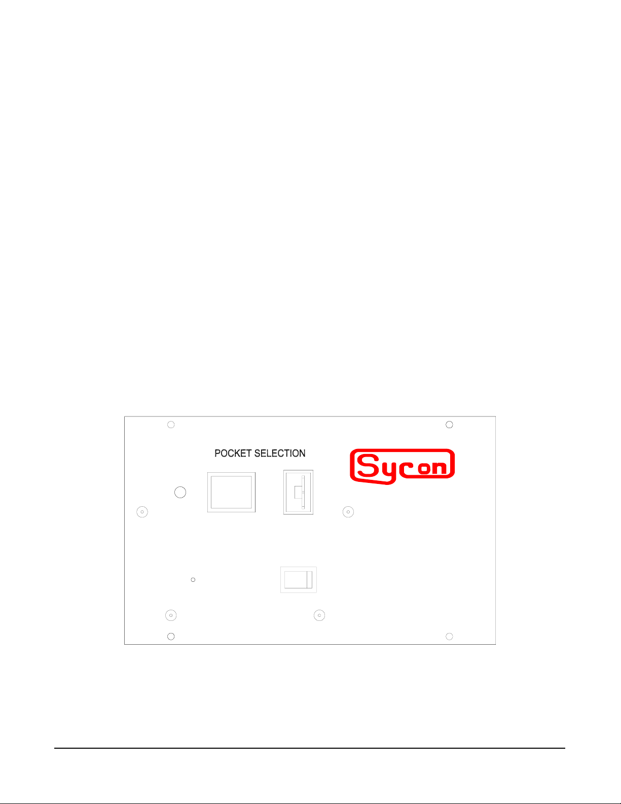
Section 2.4: Control/display features
All of the indexer’s control/display features are on the control unit’s front panel, which is
illustrated in Figure below.
Operation Page 17
Page 20
4
instruments
3
2
1
MAN
AUTO
Ø
0
ON OFF
0
SRT-422
MULT-POCKET E-BEAM INDEXER
5
Figure 2.1: Control / display features on the control unit’s front panel
1. ON/OFF switch. This switch controls the input power to the unit.
2. Phase-adjustment switch. This spring-loaded pushbutton is mounted inside a hole
below the Greek letter ph ø. See the instructions on using this switch to recalibrate the
home position of pocket 1.
3. MANual/AUTO mode switch. When this switch is set toward MAN, the position of the
thumbwheel (feature 5) controls the following functions:
• Pocket selection in all multipocket modes.
• Rotation speed in continuous mode and oscillation speed in “banana” mode.
When the switch is set toward AUTO, these functions are controlled by signals from a
host computer, deposition controller, or other remote device. These signals are input via
either the RS-232 port or the I/O (ISOLATED) connector, both of which are on the
control unit’s rear panel.
Note that this switch has a spring-loaded locking feature. You must pull the switch all
the way out and hold it out while changing its position.
4. LED pocket-position indicator. This 7-segment LED displays the numerals 0 through 7
to indicate the current pocket position. The LED also flashes between zero and the
number of the current pocket position to indicate a stalled-motor condition, which
usually results from the buildup of material along the edges of the cutout in the top of
the source.
5. Pocket/speed selection thumbwheel. When the MAN/AUTO switch is set to MANual,
this thumbwheel controls pocket selection and rotation/oscillation speed.
Page 18 Operation
Page 21

Section 2.5: Clockwise vs. counterclockwise pocket numbering
When planning multipocket deposition—with the indexer in either unidirectional or
bidirectional mode, bear in mind that the orientation of pocket numbering is determined by the
setting of internal DIP switch 5. This means that the direction of “forward” rotation (i.e., rotation
“upward” through the pocket numbers) depends on whether DIP switch 5 is set for clockwise or
counterclockwise rotation. The Figure below shows what this means for indexer operation with
a standard 4-pocket source. The pockets of such a source must be thought of as being
numbered 1-4 in a counterclockwise direction when DIP switch 5 is on and 1-4 in a clockwise
direction when switch 5 is off. The same principle applies to all multipocket sources.
HOME
HOME
1
4
3
DIP Switch 5
ON
2
1
4
3
DIP Switch 5
OFF
2
Figure 2.2: How the orientation of pocket numbering depends on the setting of DIP switch 5.
Section 2.6: Indexer operation with standard multipocket sources
The SRT-422 operates any standard 3-, 4-, 5-, 6-, or 8-pocket source that has internal 4:1 gear
reduction. When the internal DIP switches are configured for one of these source types,
operation of the indexer is straightforward. After the pocket selection has been changed either
manually via the front-panel thumbwheel or automatically by a remote device, the indexer
rotates the hearth to that pocket position at a constant rotational speed and then stops.
4-pkt. standard
(code 1)
6-pkt. standard
(code 3)
8-pkt. standard
(code 5)
Figure 2.3: Standard 4-, 6-, and 8-pocket hearths
Operation Page 19
Page 22

Source rotation can be either uni- or bidirectional if you select unidirectional rotation, you can
also select clockwise or counterclockwise rotation. If you select bidirectional rotation, the unit
will index to the selected pocket by the shortest path, whether that means rotating clockwise or
counterclockwise. Bear in mind that both uni- and bidirectional modes, the orientation of pocket
numbering depends on whether clockwise or counterclockwise rotation is selected.
Notes on This Operating Mode
1. When the indexer is configured for a standard 4-pocket source, selecting pocket
positions 1-4 moves the hearth to pockets 1-4, respectively. In addition,
Selecting pocket 5 moves the hearth to pocket 1, as indicated by the LED
Selecting pocket 6 moves the hearth to pocket 2, as indicated by the LED
Selecting pocket 7 moves the hearth to pocket 3, as indicated by the LED
Selecting pocket 8 moves the hearth to pocket 4, as indicated by the LED.
2. When the indexer is configured for a standard 6-pocket source, selecting pocket
positions 1-6 moves the hearth to pockets 1 -6, respectively. In addition, selecting either
pocket 7 or pocket S moves the hearth to pocket 1 , as indicated by the LED.
3. When the indexer is configured for a standard 8-pocket source, selecting pocket
positions 1 -8 moves the hearth to pockets 1-8, respectively. However, note that the
LED displays a zero rather than an 8 when the hearth is at pocket 8.
Section 2.7: Indexer operation with 4-pocket UHV sources
The distinguishing operating characteristic of the indexer in this mode is that it will not move
directly in either direction between pocket 1 and the pocket 90° counterclockwise from pocket
1. (The unit’s software may be thinking of the latter pocket as either pocket 2 or pocket 4.
depending on the primary rotation direction. This ‘software barrier” prevents damage to the
special bellows that is attached in this location to the hearth of a 4-pocket UHV source.
Consequently, the indexer rotates 270° to go between these two pockets in either direction.
However, because this operating mode requires the indexer to be set for bidirectional rotation,
it follows the shortest path in moving between any other pair of pockets.
CAUTION!
The indexer MUST be configured for bidirectional rotation when it is
controlling a UHV 4-pocket source. Damage to the source and/or its
bellows is likely to occur if the unit is configured for unidirectional motion.
There are no limits programmed for unidirectional motion in UIIV mode, as
there are for bidirectional motion in UHV mode.
Page 20 Operation
Page 23

Rotational range when indexer
is configured for bidirectional
motion in 4-pocket UHV mode
4-pkt. UHV
(code 7)
Figure 2.4: Illustration of a 4-pocket UHV source, indicating the position of the “software
barrier” implemented in this mode to prevent damage to the bellows attached to UHV hearths
in this area.
Section 2.8: Indexer operation with three-pocket sources that have one
banana shaped pocket
The SRT-422 can be configured to operate three-pocket sources that have two conventional
circular pockets 90º apart and one banana-shaped pocket, which can be either 12O°, 135°, or
145° in arc length or a source which has pockets 6O° apart and one 180° banana.
120
135
145
18
0
3-pkt., 120 banana
(code 10)
3-pkt., 135 banana
(code 11)
3-pkt., 145 banana
(code 12)
3-pkt., 180 banana
(code 13)
Figure 2.5: Three-pocket hearths with one banana-shaped pocket
When the indexer is properly configured to operate in this mode, selecting either pocket
1 or pocket 2 causes the indexer to rotate the hearth to one of the conventional circular
pockets. However, in this mode, the pocket-select codes for pockets 3-8 all select the bananashaped pocket. When the indexer receives any of these six pocket-select codes — either from
a remote device or from the front-panel thumbwheel — it first rotates the midpoint of the
“banana” to the home position. If the pocket-select code received by the indexer is one those
for pockets 3 through 7, the indexer then begins to oscillate the hearth in such a way that the
electron beam will sweep from one end of the “banana” to the other end. This oscillation
continues until the pocket selection is changed or until indexer rotation stops. Either because
Operation Page 21
Page 24

of interlock action or because the indexer has been switched off. As Table 3-i shows, the
speed of this oscillating motion depends on which of the pocket-select codes between 3 and 7
is received. The pocket-select code for pocket 8 causes the hearth to rotate the midpoint of the
banana to the home position and then stop. Note that this means that the electron beam will be
focused on the same point continuously until it is switched off or until another pocket is
selected.
How the speed of oscillating hearth motion in “banana” mode varies depending on the pocket
number selected
Pocket Selected Hearth Rotation Speed
3 .630 RPM
4 .515 RPM
5 .405 RPM
6 .295 RPM
7 .187 RPM
8 0 RPM
Table 2.1: Speed of Hearth in Banana Mode.
NOTE
When the indexer is configured for “banana” mode operation, internal DIP switch 5 MUST be
set for bidirectional motion. If unidirectional motion is selected, the indexer will not move the
banana-shaped pocket correctly.
Section 2.9: Indexer operation with continuous trough hearths
The SRT-422 operates in a continuous-rotation mode to support the use of full-circle evaporant
carousels (see Figure 3-6). When the indexer is properly configured for operation in this mode,
the hearth rotates continuously at any of 7 speeds in the direction determined by internal D[P
switch #5. (See section 2.3 for instructions on setting the internal DIP switches.) As the hearth
rotates, the LED displays the numerals 1-4 successively and then begins again with 1. These
numerals indicate motion relative to what would be the home position of pocket 1 on a 4pocket source.
Continuous
(code 9)
Figure 2.6: Illustration of a continuous-trough hearth
Page 22 Operation
Page 25

In this mode, the pocket-select codes whether issued via the front-panel thumbwheel or by a
remote device determine the hearth’s rotation speed. As the table below indicates, the pocketselect codes for pockets 1 through 7 select rotation speeds ranging from .187 RPM to .845
RPM, and the pocket-select code for pocket 8 stops or prevents hearth rotation. Speed
changes can be made while the hearth is rotating.
Pocket Selected Hearth Rotation Speed
0 0 RPM
1 .845 RPM
2 .732 RPM
3 .630 RPM
4 .515 RPM
5 .405 RPM
6 .295 RPM
7 .187 RPM
8 0 RPM
Table 2.2: Hearth rotation speed in continuous mode.
Section 2.10: phase adjustment
A unique front-panel feature of the SRT-422 makes it easy to reset the home position
when hearth rotation is out of phase (i.e., when the home position is no longer centered within
the cutout in the top of the source). This phase adjustment can be accomplished in either of
two ways, both of which are described in detail below. The electromechanical method
necessitates breaking vacuum and lowering and swinging out the source tray. However, this
method allows extremely precise phase adjustment. The electronic method lets you reset the
home position using front panel controls alone. However, it may prove difficult to achieve the
desired accuracy with this method, as it entails judging the accuracy of the phase adjustment
while observing the source at an angle through a view port.
Electromechanical Method
DANGER: HIGH VOLTAGE
Observe all applicable high-voltage precautions in
performing the following procedure. These precautions
include making sure that the high-voltage is OFF and using a
properly connected grounding rod to neutralize any residual
charge on the structures on and around the source tray.
STEP NO. PROCEDURE
1 Make sure that the high-voltage power supply is switched OFF.
2 If the power supply is equipped with a key lock, remove it and keep it in your
pocket while you complete this procedure.
3 Lower the source tray, open the vacuum enclosure ‘ s access doors, and swing
Operation Page 23
Page 26

the source tray away from the enclosure.
4 Using a properly connected grounding hook, touch the source tray and the frame
of the vacuum enclosure in several places to neutralize any residual high-voltage
charge.
5 Make sure the MAN/AUTO switch on the control unit’s front panel is set to MAN.
6 Use the thumbwheel on the control unit’s front panel to select pocket 1
7 Switch on the indexer, if it is not already on. After going through some rotation
involved in its initialization routine, the indexer will rotate the hearth to the factory-
set home position for pocket 1.
8 If pocket 1 is not correctly centered within the cutout in the top of the source,
switch off the indexer.
9 Turn the hearth by hand until pocket 1 is precisely centered within the cutout.
10 Using the end of a paper clip or some other small-diameter probe, push in the
spring-loaded phase adjustment pushbutton and keep it depressed as you switch
on the indexer and as the hearth goes through its initialization routine. (This
routine involves what may appear to be random rotation.) Release the
pushbutton only after the hearth has returned to the new home position for
pocket 1 and stopped. If this is not the correct home position, switch off the
indexer and repeat steps 9 and 10.
11 Use the pocket selection thumbwheel to change pockets several times, checking
to see that each pocket goes to the correct home position. If the hearth does not
remain properly in phase, return to pocket 1 and repeat steps 9 - 11.
Electronic Method
STEP NO. PROCEDURE
1 Make sure the MAN/AUTO switch on the control unit’s front panel is set to MAN.
2 Use the thumbwheel on the control unit’s front panel to select pocket 1.
3 Switch on the indexer, if it is not already on. After going through some rotation
involved in its initialization routine, the indexer will rotate the hearth to the factory-
set home position for pocket 1.
4 If pocket 1 is not correctly centered within the cutout in the top of the source,
switch off the indexer.
5 Switch the indexer on and off rapidly, watching the hearth move a small amount
each time you do so. When pocket 1 is centered in the cutout, leave the indexer
switched off.
6 Using the end of a paper clip or some other small-diameter probe, push in the
spring-loaded phase adjustment pushbutton and keep it depressed as you switch
on the indexer and as the hearth goes through its initialization routine. (This
routine involves what may appear to be random rotation.) Release the
pushbutton only after the hearth has returned to the new home position for
pocket 1 and stopped. If this is not the correct home position, switch off the
indexer and repeat steps 5 and 6.
7 Use the pocket selection thumbwheel to change pockets several times, checking
to see that each pocket goes to the correct home position. If the hearth does not
remain properly in phase, return to pocket 1 and repeat steps 5-7.
Page 24 Operation
Page 27

Section 2.11: Rotation speed and torque selection for pocket seeking
The SRT-422 provides the ability to select between three speed/torque relationships by
configuring the internal DIP switches. There is a four to one gear reduction within the source,
which produces the reduced speed and increased torque at the Hearth.
Rotation Speed Rotation Torque
Setting Indexer Hearth Indexer Hearth*
High Speed 9.25 rpm 2.31 rpm 120 In-oz. 480 In-oz.
Mid Speed 7.0 rpm 1.75 rpm 156 In-oz. 625 In-oz.
Low Speed 5.0 rpm 1.25 rpm 180 In-oz. 720 In-oz.
Table 2.3: Rotation Speed and Torque
The high speed/low torque setting is desired when you want the indexer to get to the
next pocket as soon as possible, or when you want the indexer to stop rotating in the event
that evaporant material build up is starting to causing mechanical interference between the
hearth and the cover. The low speed/high torque setting may be desired when the drive
feedthrough mechanism is producing a lot or resistance to rotation. It is also desirable when
you do not want the indexer to stop rotation (i.e. during a process sequence) in the event that
the evaporant material build up is starting to cause mechanical interference between the
hearth and the cover. In any case, if a significant amount or resistance is created by either
excessive material build-up or improperly aligned drive components, the indexer will stop
rotating and signal a stall. If a stall occurs, the pocket-position LED flashes between zero and
the number of the current pocket position. A stall can occasionally be cleared temporarily by
cycling power to the indexer, however the cause of the stall should be addressed as soon as
possible. Changing the speed torque setting affects the torque and speed when the indexer is
seeking out a new pocket, however it does not affect the speed or torque when oscillating
within a banana pocket or while in the continuous-rotation mode. While using these modes,
the torque will be greater than 180 in-oz (at the indexer) due to the slow rotation speeds.
*The value for rotation torque at the hearth in the table above does not include friction losses
or gear efficiency. The actual value would be less, and will depend on the amount of loss
within the drive system.
Operation Page 25
Page 28

Page 29

SECTION 3
INSTALLATION
Page 30

Page 31

0003
Section 3
Installation
Section 3.1: Introduction
The Indexer is shipped from the factory with an assigned home position for pocket #1.
In general, it will be difficult to install the Indexer in such a manner that home position of pocket
#1 of the Indexer correspond exactly to the actual center of pocket 1 of the source. The need
to adjust the phase between the Indexer and the E-Beam Source will generally occur after the
initial mechanical installation. There are two ways to accomplish this phase adjustment
mechanically or electronically.
The SRT-422 Motor drive is packaged in a compact case. A ¼” shaft with flat, provides
the output drive.
Figure 3.1: SRT-422 Motor Drive unit.
Section 3.2: Electrical Connections and Descriptions
Line Voltages
Unit is capable of running on both 230 Volts and 115 Volts. There is a switch located on
the connector panel of the unit to select for the proper voltage requirements.
Installation Page 29
Page 32

Figure 3.2: Line Voltage Selection Switch
The SRT-422 is supplied with an IEC type power cord for 115 Volt operation. If 230 Volt
operation is required, use the proper IEC power cord and change fuse to 1/8 amp SB.
MOTOR
RS-232
instruments
I/O (ISOLATED)
Power Cord
Ready
SRT-422
Fuse Holder
Receptacle
Line Voltage
120VAC Fuse 1/4 AMP SB
240VAC Fuse 1/8 AMP SB
Selection Switch
Figure 3.3: SRT-422 Rear Panel
WARNING! Operating with incorrect line selection will damage unit!
Section 3.3: Internal Configuration Switches
The SRT-422 is capable of controlling several different types of multi-pocket E-Beam
Sources (4 Pocket, 6 Pocket, 4 Pocket UHV, and Continuous Trough). It can also be
configured to rotate in a uni or bi-directional manner. In addition, a RS232 Serial Computer
Line at set baud rate can access it serially. The control unit contains eight internal DIP
switches that enable you to configure the unit to support your application. Four of these DIP
switches configure the indexer for use with a specific source type.
Caution! DIP switches 1-6 MUST be set properly
Internal DIP switches 1-6 MUST be set properly to configure the indexer
for the type of hearth it will be controlling. Failure to set these
switches correctly will lead to improper operation and may
Page 30 Installation
Page 33

result in damage to the source.
Section 3.4: setting the configuration dip switches
The control unit contains eight internal DIP switches that enable you to configure the
unit to support your application. Three of these DIP switches configure the indexer for use with
a specific source type. The other switches allow you to select uni- or bidirectional motion, the
rotation direction, RS -232 communications enabled/disabled, and the baud rate for RS-232
communications.
WARNING!
Procedures involving the controller’s internal circuitry
may be hazardous if attempted with the AC power cord
connected.
Before attempting to change any DIP switch settings, it is essential to ensure that the
AC power is not connected to the controller. If the unit has been in use, first use the front-panel
switch to power down the unit. Then disconnect the unit’s AC power cord.
To gain access to the DIP switches, you must slide back the control unit’s top cover. To
do so, first insert a thin, flat-bladed screwdriver beneath the rear edge of the cover and pry it
up enough so that the retainer dimple in its rear edge clears the top edge of the controller’s
rear panel. Then you can easily slide the cover back by applying thumb pressure to it and
pushing rearward. When you have finished setting the DIP switches, slide the cover forward
until the retainer snaps into place, firmly securing the cover. The switch block containing the
DIP switches is mounted along the front edge of the controller’s main printed circuit board. If
you look at the board from a position above the front panel, you will see the switch block near
the right-hand edge of the board. The DIP switches are on the side of the switch block that
faces the front panel. Note that they are numbered I through 8 from left to right, as viewed from
the front end of the control unit.
The figure below illustrates the eight DIP switches from this point of view and lists the
effects of their settings in tabular form. Note that these switches slide rather than rock up and
down to change position and that the ON position is up.
Installation Page 31
Page 34

1 2 3 4 5 6 7 8
SWITCH 6:
ROTATION DIRECTION
SWITCH 5:
UNI / BI DIRECTIONAL
SWITCHES 1-4:
SOURCE TYPE
= SWITCH IN UP (ON) POSITION
SW7 SW8 Function
OFF OFF High Speed, Low Torque 9.25 120
ON OFF Mid Speed, Mid Torque 7.00 156
OFF ON Low Speed, High Torque 5.00 180
ON ON Not Assigned
SW6
Clockwise ON
CounterClockwise OFF
SW5
BIDIRECTIONAL
UNIDIRECTIONAL
Code Function SW1 SW2 SW3 SW4
0 STD. 3-Pocket, 120 apart OFF OFF OFF OFF
1 STD. 4-Pocket, 90 apart ON OFF OFF OFF
2 STD. 5-Pocket, 72 apart OFF ON OFF OFF
3 STD. 6-Pocket, 60 apart ON ON OFF OFF
4 not assigned OFF OFF ON OFF
5 STD. 8-pocket, 45 apart ON OFF ON OFF
6 not assigned OFF ON ON OFF
7 UHV 4-Pocket ON ON ON OFF
8 not assigned OFF OFF OFF ON
9 Continuous ON OFF OFF ON
10 3-pkt(120 Ban), pkts 90 apart OFF ON OFF ON
11 3-Pkt(135 Ban), pkts 90 apart ON ON OFF ON
12 3-Pkt(145 Ban), pkts 90 apart OFF OFF ON ON
13 3-Pkt(180 Ban), pkts 90 apart ON OFF ON ON
14 not assigned OFF ON ON ON
15 not assigned ON ON ON ON
OFF
ON
Speed RPM torque in-oz
Figure 3.4: Configuration Switch
Internal switches select all the above modes or functions. An eight-position dipswitch is
located at the top end of the main control printed circuit board within the SRT-422. To access
this switch, first disconnect any line power. Remove the six socket head cap screws, which
hold the bottom connector panel to the side extrusions. Slide out the back panel and PC
Boards until this switch is accessible. Make the desired configuration settings and reassemble
the unit.
Section 3.5: Description of Configuration Switches
SW1, SW2, SW3, SW4 -- The first four switches are used to match the Indexer to the type of
source being controlled.
SW5 -- Rotation Type. Controls whether the Indexer moves in a single direction or a bi-
directional path. (Bi-directional should be selected if shortest path operation is desired).
Switch 5 allows you to select uni- directional or bi-directional rotation. If uni-directional
rotation is selected (switch 5 ON), the direction of rotation is determined by the setting of
switch 6. If bidirectional rotation is selected (switch 5 OFF), the indexer will employ
shortest-path indexing in moving between the pockets of rnultipocket sources.
Page 32 Installation
Page 35

SW6 -- This switch defines the relationship between pocket 1 and pocket 2 of the source. It
should be set at the same sense, which the Indexer should rotate to move the source
between pocket 1 and pocket 2, e.g. clockwise or counter clockwise. The setting of
switch 6 determines the direction of hearth rotation in unidirectional mode and the
primary rotation direction in bidirectional mode. For both uni- and bidirectional
operation, the orientation of pocket numbering (i.e., which direction is “forward” or
upward though the pocket numbers) also changes depending on the setting of DIP
switch 6. The figure below illustrates this in the case of a 4-pocket source. When DIP
switch 6 is on, the indexer will operate such a source as if its pockets were numbered 14 counterclockwise (hearth rotates clockwise). When this switch is off, the indexer will
operate the same source as if its pockets are numbered 1-4 clockwise (hearth rotates
counterclockwise). The same principle applies to all other source types.
HOME
4
OFF
CLOCKWISE/COUNTER-CLOCKWISE FROM MOTOR'S POINT OF VIEW
Figure 3.5: Orientation of pocket numbering changes depending on the setting of DIP switch 6
(Note: The output shaft of the index drive unit rotates counterclockwise when D/P switch 5 is
on and clockwise when this switch is off. Because of the effect of the internal gears in the
sources supported by the SRT-422, output shaft rotation is in the opposite direction from
hearth rotation.)
When planning for multipocket deposition, it is critical to bear in mind that
the setting of switch 6 determines the orientation of pocket numbering.
The pockets of a 4-pocket source must be thought of as being numbered
1-4 in a clockwise direction when switch 6 is on and 1-4 in a
counterclockwise direction when switch 6 is off.
1
3
2
NOTE
HOME
4
ON
1
3
2
SW7, SW8 -- Rotation Speed and Torque As shown, Switch 7 and 8 allow you to select
between three speed and torque settings. If high speed is selected (switch 7 and
8 OFF) the indexer will seek out the next pocket, when commanded, at the
highest speed rate. If mid-speed is selected (switch 7 OFF and switch 8 ON) the
indexer will seek out the next pocket at an intermediate speed and torque. If
low-speed is selected (switch 7 OFF, switch 8 ON) the indexer will produce the
highest torque while seeking out the next pocket, however it will be at a Lower
speed.
Installation Page 33
Page 36

3-pkt. standard
(code 0)
Continuous
(code 9)
4-pkt. standard
(code 1)
3-pkt., 120 banana
(code 10)
5-pkt. standard
(code 2)
120
6-pkt. standard
135
3-pkt., 135 banana
(code 11)
(code 3)
8-pkt. standard
(code 5)
145
3-pkt., 145 banana
(code 12)
4-pkt. UHV
(code 7)
180
3-pkt., 180 banana
(code 13)
Figure 3.6: Source types supported by the SRT-422
Standard Multi-pocket Sources (Codes 0-5)
When switches 1-4 are set for code 1, the unit is configured to operate a standard 4-pocket
source. When these switches are set for code 3, the unit is configured to operate a standard 6pocket source. When these switches are set for code 5, the unit is configured to operate a
standard 8-pocket source. The switch positions that select these codes are:
Code
Number
DIP
SW1
DIP
SW2
DIP
SW3
DIP
SW4
Code 0 OFF OFF OFF OFF
Code 1 ON OFF OFF OFF
Code 2 OFF ON. OFF OFF
Code 3 ON ON OFF OFF
Code 5 ON OFF ON OFF
Table 3.1: Codes 0 – 5 DIP Switches settings.
UHV 4-Pocket Sources (Code 7)
If the SRT-422 is to be used with a UHV 4-pocket source, switches 1-4 must be set for code 7.
In addition, switch 5 must be set for bidirectional motion. The switch positions that select code
7 are:
Code
Number
DIP
SW1
DIP
SW2
DIP
SW3
DIP
SW4
Code 7 ON ON OFF OFF
Table 3.2: Code 7 DIP switch settings
Page 34 Installation
Page 37

CAUTION!
Switches 1-5 MUST he set as described above when the
SRT-422 is controlling a UHV 4-pocket source. Damage to
the source and / or its bellows are likely to occur if switches
1-4 are set for a UHV source and switch 5 is set for
unidirectional rotation There are no limits programmed for
unidirectional motion in UHV mode, as there are for
bidirectional rotation in that mode.
This mode has a programmed “software barrier” that prevents the hearth from rotating in
either direction between pocket 1 and the pocket next to it in the counterclockwise direction.
This programming serves to prevent damage to the special bellows attached to the hearth in
that location on UHV sources. To move the hearth between these two pockets, the indexer
does not simply rotate the hearth 90° along the shortest path. Instead, the hearth is rotated
270° in the opposite direction. The indexer employs shortest-path rotation when rotating the
hearth between any two other pockets.
Three-Pocket Hearths with One Banana-Shaped Pocket (Codes 10-13)
When switches 1 - 4 are set to codes 10, 11, 12 and 13, the indexer is configured for hearths
with two conventional pockets 90° apart and one banana-shaped pocket. These three codes
configure the indexer to support “bananas” of differing arc lengths.
• Code 10 sets the indexer for a three-pocket hearth with a “banana” covering 120° of arc.
• Code 11 sets the indexer for a three-pocket hearth with a “banana” covering 135° of arc.
• Code 12 sets the indexer for a three-pocket hearth with a “banana” covering 145° of arc.
• Code 13 sets the indexer for a three-pocket hearth with a ‘banana” covering 180° of arc.
The switch positions that select these codes are:
Code
Number
DIP
SW1
DIP
SW2
DIP
SW3
DIP
SW4
Code 10 OFF ON OFF ON
Code 11
Code 12
ON
OFF
ON OFF ON
OFF ON ON
Code 13 ON OFF ON ON
Table 3.3: Codes 10 – 13 DIP switch settings
NOTE
When switches 1-4 are set to any of these FOUR codes, switch 5 MUST
be set for bidirectional motion. If unidirectional motion is
selected, the indexer will not move the “banana” correctly.
In any of these “banana” modes, the indexer moves pockets 1 and 2 to the home
position when it receives the pocket-select codes for those pockets. When the
Installation Page 35
Page 38

indexer receives any of the pocket-select codes for pockets 3 through 7, it moves
the banana-shaped pocket to the home position and then begins oscillating the
hearth in such a way that the e-beam sweeps from one end of the “banana” to the
other. Pocket select codes 3-7 determines the speed of the oscillating motion, as
the Table below indicates. When the indexer receives the pocket-select code for
pocket 8, it moves the midpoint of the “banana” to the home position and stops.
Hearths with Full-Circle Evaporant Troughs (Code 2)
If switches 1-3 are set for this type of hearth (code 2), the hearth will rotate continuously
in the direction set via switch 5. The setting of switch 4 has no effect on rotation in this mode.
The switch settings that select code 2 is in this mode, the pocket-select codes for pockets
through 7 determine the hearth’s rotation speed, as indicated in the table below. The pocketselect code for pocket 8 stops or prevents hearth rotation.
Pocket Selected Hearth Rotation Speed
1 .845 RPM
2 .732 RPM
3 .630 RPM
4 .515 RPM
5 .405 RPM
6 .295 RPM
7 .187 RPM
8 0 RPM
Table 3.4: Hearth rotation in continuous mode .
Page 36 Installation
Page 39

Section 3.6: configuring the opto-isolator pc board for 24-vdc I/Os
The control unit’s opto-isolated I/Os are factory configured to operate on 9 V dc supplied by an
internal power supply. However, the control unit’s opto-isolator board can also be configured to
operate on +24 V dc supplied by an external source. Follow the steps described below to
accomplish this reconfiguration.
STEP NO. PROCEDURE
1 Make sure the power cord is not connected to the control unit.
2 Remove the four screws that secure the control unit’s rear panel (see Figure
Below).
MOTOR
RS-232
Ready
instruments
SRT-422
I/O (ISOLATED)
Remove these Screws to det ach
rea r panel from body.
120VAC Fuse 1/4 AMP SB
240VAC Fuse 1/8 AMP SB
Figure 3.7: Locations of screws that secure the control unit’s rear panel to its body
3 Grasp the rear panel and pull it backwards until it is approximately an inch away
from the body of the controller.
4 The jumper blocks to be reconfigured are mounted on the underside of the opto-
isolator PC board, which is the topmost board in the unit. Turn the control unit
upside down and find the legend JP1 on the underside of this board. You will find
this legend near the rear of the board and along the edge of the board that is
closest to the rear-panel connector labeled I/O (ISOLATED). Jumper block JPI is
just behind the legend JP1 (or just to the right of this legend, if you are looking at it
from the side of the controller).
5 The pins on jumper block JPI are numbered from left to right as you face the side of
the controller that the jumper block is on. From that point of view, pin 1 is on your
left, pin 2 is in the middle, and pin 3 is on your right. The jumper across this jumper
block is factory installed so that it covers pins 1 and 2, leaving pin 3 exposed.
Remove the jumper and replace it so that it covers pins 2 and 3, leaving pin 1
exposed.
7 JP2 is behind and at right angles to JP1 (i.e., behind JP1 with respect to the
controller’s front panel). On this jumper block, pin 1 is the pin nearest the edge of
the board; pin 2 is in the center, and pin 3 is nearest to the center of the board. Like
Installation Page 37
Page 40

JP1 , this jumper block is factory configured so the jumper covers pins 1 and 2,
leaving pin 3 exposed. Remove the jumper and replace it so it covers pins 2 and 3,
leaving pin 1 exposed.
8 Grasp the controller’ s rear panel and slide it forward until it is in contact with the
body of the controller. As you do so, take care that the green ground wire
connected to the inside of the rear panel does not get pinched between the rear
panel and the controller’s body.
9 Replace the four screws that secure the rear panel to the body of the controller.
Section 3.7: Initial Bench Test
After the configuration dipswitch has been set to the desired pocket type and the unit is
reassembled it is useful to confirm the setting by running the unit on the test bench. To do this
first connect the 15-pin Remote Selection Panel cable to the Indexer. Attach the power cord
and plug in to appropriate voltage. (See line voltage selection Refer to Section 3.2). Turn on
power switch on bottom of Indexer. Place remote panel Auto/Man switch the manual mode .
Select the different pocket number using the thumbwheel switch and observe the rotation of
the output shaft of the Indexer. Remember this model of the Indexer is design for 4 to 1
reduction between the Indexer and the rotatable hearth. This means the Indexer will turn 360
degrees for a 90-degree rotation of the hearth.
It is a good idea to bench test the indexer after the control unit is configured for your
application. Follow the steps described below in performing this test.
STEP NO. PROCEDURE
1 Find the motor cable. This is the 25-foot cable supplied to connect the control unit
to the index drive unit.
2 The motor cable has a 1 5-pin ‘D’ connector on each end. Plug the male ‘D’
connector on one end of the cable into the socket labeled MOTOR on the control
unit’s rear panel.
3 Plug the female ‘D’ connector on the other end of the motor cable into the 15-pin
male connector on the end of the index drive unit.
4 Make sure the input power selection switch is set for the correct voltage
WARNING
Operating the SRT-422 with incorrect line voltage
selected will damage the unit.
5 Make sure the power switch on the control unit’s front panel is OFF.
6 Plug the correct power cable for the local AC power into the three-pronged plug on
the control unit’s rear panel. Plug the other end of this cable into an AC power
socket.
7 Make sure the MAN/AUTO toggle switch on the control unit’s front panel is set to
Page 38 Installation
Page 41

MAN. Note that this switch has a locking feature. To change its position, you must
first pull the locking collar out toward you.
8 Set the front-panel thumbwheel to position 1, if it is not already at that position.
9 Using the ON/OFF switch on the control unit’s front panel, switch on the indexer. If
the internal DIP switches are set for a full circle evaporant carousel, the drive unit’s
output shaft will begin rotating continuously at its highest speed. If the DIP switches
are set for any other type of source, the indexer will stop at the factory-set home
position for pocket 1 after proceeding through various rotations involved in its
initialization routine.
10 Change thumbwheel setting to select pocket 2. The indexer rotates to the pocket -2
position after going through rotations that vary depending on the settings of DIP
switches 1-5.
11 Use the thumbwheel to select other pockets and observe the rotation of the output
shaft.
12 When you have completed the bench-test, switch off the control unit, disconnect the
AC power cable from the rear panel, and disconnect the motor cable from both the
control unit and the index drive unit.
Section 3.8: System Installation
The standard unit is designed to be used with the E-Beam source, which has a 4 to 1
reduction within the source or a 4 to 1 reduction between the Indexer output shaft and the
source. Thus 360 degrees of rotation of the Indexer shaft will cause a 4 pocket source to
rotate 90°.
The most cost effective system installation is accomplished by the purchase of either
the 1” or 2 ¾” Rotary Feedthrough Indexer and Adapter Kits from Sycon. If system
configuration of space does not allow the use of these standard items, the Indexer should be
rigidly mounted and the Indexer drive shaft be appropriately attached (minimum slop and
backlash) to the airside of the Rotary Feedthrough.
A one-to-one directed connector is needed between the output shaft of the Indexer and
the airside of the Rotary Vacuum Feedthrough. Sycon stocks the following items to assist in
making the Mechanical connection from the output shaft of the Indexer to the air side of the
Rotary Vacuum Feedthrough:
Installation Page 39
Page 42

Figure 3.8: Motor Drive Unit
Section 3.9: Installing the Index-Drive Unit
The Figure above shows the index-drive unit properly installed on the underside of the source
tray. The drive unit is held in place by the large nut on the underside of the 1 -inch-dia. rotary
feedthrough.
DANGER: HIGH VOLTAGE
If a high-voltage power supply is installed in the vacuum
system in which the SRT-422 is to be installed, observe all
applicable high-voltage precautions in performing the
following procedure. These precautions include making sure
that the high-voltage is OFF and using a properly connected
grounding rod to neutralize any residual charge on the
structures on and around the source tray.
Follow the procedure described below in installing the drive unit.
STEP NO. PROCEDURE
1 Perform the following sub steps only if a high-voltage power supply is connected to
the vacuum system in which the SRT-422 is being installed. Otherwise, proceed to
step 2.
Page 40 Installation
Page 43

(a) Make sure that the high-voltage power supply is switched OFF.
(b) If the power supply is equipped with a keylock, remove it and keef, it in
your pocket while you complete this procedure.
2 Lower the source tray, open the vacuum enclosure’s access doors, and swing the
source tray out from the enclosure.
3 (This step may be skipped if a high-voltage power supply has not been connected
to the vacuum system in which you are installing the SRT-422.) Using a properly
connected grounding hook, touch the source tray and the frame of the vacuum
enclosure in several places to neutralize any residual high-voltage charge.
4 Remove the attachment nut and flat washer (see Fig. 2-7) from the rotary
feedthrough.
5 Put coupling PN 9015-0121-01 in place over the feedthrough input shaft and secure
the coupling to that shaft with the coupling’s upper set screw.
WARNING
To prevent binding during source rotation and to minimize
alignment problems, it is essential to use the same type of
flexible coupling to connect the feedthrough output shaft to
the source’s drive shaft.
6 Place the index-drive unit against the underside of the source tray so that the
feedthrough threaded shaft extends through the hole in the yoke that spans the top
of the drive unit. Make sure that the drive unit’s output shaft fits up into the coupling.
7 Lower the index drive unit enough to put the flat washer and attachment nut back in
place around the threaded portion of the feedthrough. Then restore the drive unit to
the position described in step 6.
8 Screw the attachment nut all the way on, tightening it to approximately 10 ft-lbs.
9 Secure the coupling to the drive unit by tightening the coupling’s lower set screw
against the drive unit's output shaft.
10 Connect the female 'D' connector on one end of the motor cable to the ‘D’
connector on the index-drive unit, securing the connection with the screws on the
‘D’ connector.
Section 3.10: Installing the Control Unit
Follow the procedure described below in mounting the control unit in a standard 1 9-inch
electronics rack.
STEP NO. PROCEDURE
1 Disconnect any cables that have been connected to the control unit’s rear panel.
Installation Page 41
Page 44

2 Put the half-with control unit in place a 5-1/4-in-high space in the electronics rack.
3 Secure the front panel to the rack with the four screws and cup washers provided.
4 Connect the input power cable to the plug on the control unit’s rear panel.
5 Plug the other end of the power cable into a wall socket.
6 Make sure that the line voltage selection switch is set correctly (see Fig. 2-2)..
WARNING
Operating the SRT-422 with incorrect line voltage selected will
damage the unit.
7 Connect the male ‘D’ connector on one end of the motor cable to the MOTOR
connector on the control unit’s rear panel. Use the screws provided on the ‘D’
connector to secure it to the MOTOR connector.
Section 3.11: Indexer and System Grounding
A grounding stud is provided on the control unit’s rear panel. Use a 16-gauge or larger wire
to ground this stud to the electronics rack. Because the rack as a whole is likely to be subject
to RF interference, it is strongly recommended that a low-impedance ground be provided for
the system. The figure below shows a method of setting up such a ground.
CHAMBER
Crystal Sensor
I/O (ISOLATED)
MOTOR
instruments
RS-232
SRT-422
SHUTTER
Chamber ground
To Control Unit
Ready
120VAC Fuse 1/4 AMP SB
240VAC Fuse 1/8 AMP SB
Indexer
Figure 3.9: SRT-422 Grounding
Page 42 Installation
Page 45

A
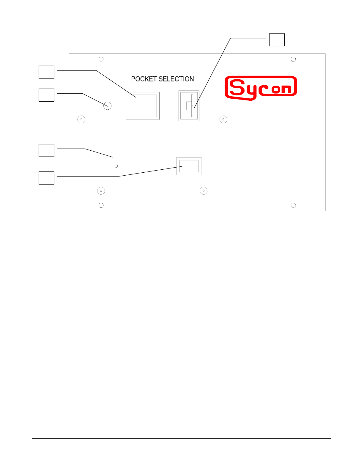
Section 3.12: initial phase adjustment
The home position will almost certainly have to be reset after the indexer is installed. This
initial phase adjustment can be accomplished in either of two ways, both described in detail
below. The electromechanical method necessitates breaking vacuum and lowering and
swinging out the source tray. However, this method allows extremely precise phase
adjustment. The electronic method lets you reset the home position using front panel controls
alone. However, it may prove difficult to achieve the desired accuracy with this method, as it
entails judging the accuracy of the phase adjustment while observing the source at an angle
through a view port.
Manual / Auto Mode
Switch
ON / OFF Switch
Phase Adjustment
Pushbutton
Figure 3.10: Control/display features on the control unit’s front panel
Pocket
Position
LED
Pocket Selection Thumbwheel
MAN
0
ON OFF
SRT-422
UTO
Ø
0
MULT-POCKET E-BEAM INDEXER
instrument
Electromechanical Method
DANGER: HIGH VOLTAGE
If a high-voltage power supply is installed in the vacuum system in which the SRT-422 has
been installed, observe all applicable high-voltage precautions in performing the following
procedure. These precautions include making sure that the high-voltage is OFF and using a
properly connected grounding rod to neutralize any residual charge on the structures on and
around the source tray.
STEP NO. PROCEDURE
1 Perform the following sub steps only if a high-voltage power supply is
connected to the vacuum system in which the SRT-422 is being installed.
Otherwise, proceed to step 2.
(a)Make sure that the high-voltage power supply is switched OFF.
Installation Page 43
Page 46

(b)If the power supply is equipped with a key lock, remove it arid keep it in your
pocket while you complete this procedure.
2 Lower the source tray, open the vacuum enclosure’s access doors, and swing
the source tray away from the enclosure.
3 (This step may be skipped if a high-voltage power supply has not been
connected to the vacuum system in which you are installing the SRT-422.)
Using a properly connected grounding hook, touch the source tray and the
frame of the vacuum enclosure in several places to neutralize any residual
high-voltage charge.
4 Make sure the MAN/AUTO switch on the control unit’s front panel is set to
MAN.
5 Use the thumbwheel on the control unit’s front panel to select pocket 1.
6 Switch on the indexer, if it is not already on. After going through some rotation
involved in its initialization routine, the indexer will rotate the hearth to the
factory-set home position for pocket 1.
7 If pocket 1 is not correctly centered within the cutout in the top of the source,
switch off the indexer.
8 Turn the hearth by hand until pocket 1 is precisely centered within the cutout.
9 Using the end of a paper clip or some other small-diameter probe, push in the
spring-loaded phase adjustment pushbutton and keep it depressed as you
switch on the indexer and as the hearth goes through its initialization routine.
(This routine involves what may appear to be random rotation.) Release the
pushbutton only after the hearth has returned to the new home position for
pocket 1 and stopped. If this is not the correct home position switch off the
indexer and repeat steps 8 and 9.
10 Use the pocket selection thumbwheel to change pockets several times,
checking to see that each pocket goes to the correct home position. If the
hearth does not remain properly in phase, return to pocket 1 and repeat steps
8-10.
Electronic Method
STEP NO. PROCEDURE
1 Make sure the MAN/AUTO switch on the control unit’s front panel is set to
MAN.
2 Use the thumbwheel on the control unit’s front panel to select pocket 1.
3 Switch on the indexer, if it is not already on. After going through some rotation
involved in its initialization routine, the indexer will rotate the hearth to the
factory-set home position for pocket 1.
4 If pocket 1 is not correctly centered within the cutout in the top of the source,
switch off the indexer.
Page 44 Installation
Page 47

5 Switch the indexer on and off rapidly, watching the hearth move a small amount
each time you do so. When pocket 1 is centered in the cutout, leave the indexer
switched off.
6 Using the end of a paper clip or some other small-diameter probe. push in the
spring-loaded phase adjustment pushbutton and keep it depressed as you
switch on the indexer and as the hearth goes through its initialization routine.
(This routine involves what may appear to be random rotation.) Release the
pushbutton only after the hearth has returned to the new home position for
pocket 1 and stopped. If this is not the correct home position, switch off the
indexer and repeat steps 5 and 6.
7 Use the pocket selection thumbwheel to change pockets several times,
checking to see that each pocket goes to the correct home position. If the
hearth does not remain properly in phase, return to pocket 1 and repeat steps
5-7.
Section 3.13: making system connections via the rear panel I/O interface
The I/O (ISOLATED) connector on the control unit’s rear panel provides an opto-isolated
interface for exchanging digital signals with other system components. The user must supply
cabling between this connector and external devices. The figure below identifies the signals
that can be exchanged via this connector and shows the function of each pins Power for the
I/Os can be either internally or externally supplied. If internally supplied, the I/Os are -9 Vdc
when low and +9 Vdc when high. If externally supplied, they are 0 Vdc when low and +24 Vdc
when high. Outputs are limited by the indexer’s internal circuitry to a maximum of 10 ma per
output. If you use the internal +/- 9 Vdc supply, connect pin 1 4 on the I/O connector as the
ground. If an external +24 Vdc is supplied, connect pin 15 as the ground.
Interlock Connections
One of two signals (either the POCKET GOOD output or the system interlock input) must be
connected to provide an interlock that will prevent the e-beam from damaging portions of the
hearth while it is rotating. The POCKET GOOD output is high as long as a given pocket is
within 5° of the calibrated home position. To use this signal as the indexer’s interlock, connect
pin 5 on the I/O connector to the electron beam power supply in such a way that the power
supply is switched off when POCKET GOOD goes low. If you are using a Temescal Simba 2
power supply, connect this wire to the input for the power supply’s AUXiliary interlock. Refer to
the Simba 2 manual for detailed instructions.
Alternatively, if a system interlock signal is input via pin 3, the signal high when as it is not safe
for the hearth to rotate. Such an interlock would prevent hearth rotation when the e-beam is
on. However, this arrangement would not protect the source from damage if the hearth should
get severely out of phase.
Installation Page 45
Page 48

9 Pocket Position 0 output
10 +24 Vdc input
11 Not Used
12 Not Used
13 Not Used
14 Internal supply ground
15 External supply ground
9 10 11 12 13 14 15
1 2 3 4 5 6 7 8
1 Pocket Select 0 input
2 Pocket Select 1 input
3 System interlock input
4 Pocket Position 1 output
5 Pocket Good Output
6 External supply ground
7 Pocket Select 2 Input
8 Pocket Position 2 output
Figure 3.11: Pinout for the rear panel I/O (ISOLATED) connector
Pins 1, 2, and 7 (Pocket SELect Inputs 0,1, and 2 respectively)
When the front-panel MAN/AUTO switch is set to AUTO, these inputs control pocket selection
in multipocket modes and rotation speed in banana and continuous modes. Table 2-3 shows
the digital code required to select each pocket and correlates those codes to the pins 1 , 2, and
7.
Pocket 1 2 3 4 5 6 7 8
LSB A Pin 1 (SEL 0) 0 1 0 1 0 1 0 1
B Pin 2 (SEL 1) 0 0 1 1 0 0 1 1
MSB C Pin 7 (SEL 2)** 0 0 0 0 1 1 1 1
Table 3.5: Pocket-select codes input via pins 1, 2, and 7
**SEL2 not required for four pocket configurations
Pin 3 (System Interlock Input)
This is a user-defined interlock input. The drive motor cannot turn when this signal is true.
Pins 4, 8, and 9 (Pocket POSition Outputs 1, 2, and 0, respectively)
These outputs indicate the current pocket location. The Table below shows the digital code for
each pocket position and correlates those codes to pins 4, 8, and 9.
Pocket 1 2 3 4 5 6 7 8
LSB Pin 9 (POS0) 0 1 0 1 0 1 0 1
Pin 4 (POS1) 1 0 0 1 1 0 0 1
MSB Pin 8 (POS2) 1 1 1 0 0 0 0 1
Table 3.6: Pocket-position codes output via pins 4, 8, and 9
Page 46 Installation
Page 49

Pin 5 (POCKET GOOD Output)
This output is high when the selected pocket is within 5° of the calibrated home position.
Directions for using this signal as the indexer’s interlock are provided above.
Pin 6 (External Supply Ground)
If you are providing +24 V dc from an external source to power the I/Os, either this pin or pin
15 must be connected to the ground of the external power supply.
Pin 10 (External Supply Positive Input)
Pin 10 is the input point for the externally supplied +24 Vdc that can be used to power the I/Os.
The control unit’s opto-isolator PC board must be reconfigured if you wish to use 24-V I/Os.
Pins 11, 12, and 13
Not used.
Pin 14 (Internal Supply Ground)
If you are using the internally supplied voltage (9 Vdc) to power the I/Os, a ground for this
supply must be connected to pin 14 the unit is factory configured to operate with this voltage.
Pin 15 (External Supply Ground)
This pin is internally connected to pin 6. Ground for the external supply can be connected to
either pin.
Section 3.14: making system connections via the rear panel rs232 interface
The RS-232 connector on the control unit’s rear panel enables you to establish serial
communications between the SRT-422 and a host computer, a deposition controller, or
another system component. This section describes the interconnection details. For further
information on implementing serial communications see the section on serial protocol.
The user must supply cabling for RS-232 communications. The figures below show the pin-bypin connections required. The figure shows how the 9-pin male connector that would plug into
the indexer’s RS-232 port must be wired to a 9-pin connector that would plug into the RS-232
port on an external device. Figure also shows how the 9-pin male connector that would plug
into the indexer must be wired to a 25-pin connector that would plug into the external device.
Installation Page 47
Page 50

E
TO INDEXER (RS232)
2 RxD
⇐
3 TxD
⇒
9
5 GND
9 PIN MALE
SHIELD
INTERFACE
⇒
DSR 6
⇒
RxD 2
⇐
TxD 3
⇒
CTS 8
DTR 4
⇐
GND 5
9 PIN FEMALE
TO INDEXER (RS232) INTERFACE
2 RxD
9 PIN MALE
3 TxD
9
5 GND
⇐
⇒
SHIELD
⇐
TxD 2
⇒ RxD 3
⇒ CTS 5
⇒
DSR 6
GND 7
⇐
DTR 20
25 PIN FEMAL
Figure 3.12: Connections required for RS-232 communications between the SRT-422 and a
remote device with a 9-pin RS-232 port and a 25 pin RS-232 port.
Section 3.15: Warranty Repair and Replacement
5 Year Service Policy
Sycon warrants the SRT-422 for 1 year. After that period, Sycon will replace or repair
the SRT-422 for a fixed charge of $175 during the 4 additional years. Rotary Vacuum
Feedthrough are warranted by the manufacturer
Page 48 Installation
Page 51

Section 4
Serial Communications
Page 52

Page 53

0004
Section 4
Computer Interfacing
The Source Indexer can be connected to a computer or system controller through its
standard RS-232 interface. A simple ASCII protocol is used to send data or commands to, or
to read data from the SRT. This section will describe this protocol and the command set and
the cabling required for operation with a PC.
RS-232 Interface
Section 4.1: RS-232 Description
RS-232 is an electrical specification for the transmission of data in a serial format. It
defines and establishes the electrical compatibility of the communication link between two
pieces of RS-232 equipped instruments. In addition to this RS-232 link a language of
communication and a command set must be defined. Since most every piece of equipment
has different data requirements, more often than not, the commands and the protocol to
communicate to an instrument are unique.
Like the manual use of the Indexer, the RS-232 command set and protocol of the unit
are simple and straightforward.
Section 4.2: Baud Rates And Cabling
After the proper cable connections are made, the baud rate of the computer and the
SRT should be checked or set so that they are set the same.
Section 4.3: Setting The computer Baud Rate
If required, change the baud rate on your computer to the same baud rate as the SRT.
The SRT is shipped from the factory set at 9600 baud. To set a PC to the 9600 baud rate,
type in the DOS command:
Mode Com1:9600,N,8,1 <Enter>
This will set the PC for 9600 baud, no parity, 8 data bits, and 1 stop bit on its COM1
port. It is important to use 8 data bits because the protocol uses all of them. This assumes the
SRT is cabled to COM1 of the PC type computer.
Computer Interfacing Page 51
Page 54

Section 4.4: ASCII Protocol
The SRT does not initiate any messages on its own. It responds only when “spoken” to
. The format of the ASCII protocol used to send a message to the SRT is as follows:
$byte (byte) (byte...byte)CR
The ‘$’ is the start of a message. A single ASCII character is a byte. Either a space or
comma separates different parameters in the command. Parameters can have multiple bytes.
No space or comma separator exists between the ‘$’ and the first byte or the last byte and the
CR. The number of parameters in a message depends on the command. A CR terminates the
message. In the following paragraphs the CR (Carriage Return) or, optionally, the CR LF will
be designated by <cr>.
Page 52 RS-232 Interface
Page 55

Section 4.5: Communication Commands
A set of commands follow which when used allow control of and communications with
the Source Indexer by a process controller or a PC type computer. These commands follow
the ASCII protocol described above. The function of each command along with its form and a
typical response is described below. Note: In a response, the first byte after the ‘$’ is the
response byte which encodes the success or failure of the command and the status of the
reset flag. See the paragraph following the command set for a complete explanation of the
response byte.
Section 4.6: Command Responses
In response to all messages received with a valid protocol, the first byte returned after
the ‘$’ is the response byte which may be one of the following.
Reset Flag Cleared Reset Flag Set
Message OK ‘*’ ‘#’
Illegal Command ‘3’ ‘4’
Illegal Data Value ‘5’ ‘6’
Illegal Syntax ‘7’ ‘8’
All commands received with a valid protocol (‘$’ first char and <cr> last char) will return
some type of response based on the message received and the state of the Reset Flag. The
Reset Flag is set when power is first applied to the unit. The Flag remains set until it is cleared
by the RS-232 command R. The purpose of the Reset flag is to notify a remote control source
that the SRT has been turned off and back on again or a power failure has occurred so it may
take the appropriate steps if necessary. A typical control program would initially clear the
Reset flag, then test the response byte of each response to see if some type of power failure
has occurred.
For example, assume you have written a program to talk to the Indexer through the
serial port. Your program is running and you set the current pocket to Three (3). After the
pocket is set you have a power failure of short duration and the SRT is reset. Next you may
issue a command and you notice the response byte indicates you had a power failure. This
may be a problem for the following reason. Your program assumes you have set the current
pocket of 3, but on a power fail reset the unit to pocket 1. An appropriate action at this point
may be to set the correct pocket.
Response to a valid Set Parameter command. A response to a successful set
command with the reset flag cleared would be $*<cr> where $ and <cr> are the protocol, *
says the message was received and there has been no power failures since the Reset flag
was cleared.
Response to a valid Ask Parameter command
A response to a successful ask command with the reset flag set would be $#1.5<cr> where #
indicates there has been a power failure (if you reset the flag when your program started) the
1.5 indicates the value of the parameter you requested.
RS-232 Interface Page 53
Page 56

Section 4.7: ‘Illegal’ Responses
All messages with the proper protocol ($.......<cr>) will be processed by the Source
Indexer. If the content or form of the message of the message is determined to be incorrect by
the Source Indexer one of the following messages will be returned.
Note:
Illegal Command A command code (first byte) which the SRT does not recognize has
Illegal Data Value The data value or parameter sent following the command code is
Illegal Syntax This indicates the format of the data is incorrect. Wrong number of
If the protocol sent or baud rate used is not correct the SRT will not
respond to the transmitted message.
been sent.
out of range or an incorrect code.
data parameters sent for the command used. Or, improper
delimiters between data.
Section 4.8: Command Set
Query the unit for any operating parameter
$<Parameter>?<cr>
Version Command @
$@<cr> Version Query: Returns Software Version
Response: $*SRT422VXXXX<cr>
This command reports the identity of the instrument and the version # of the firmware
installed. This command is useful in initially testing the communications link and in the initial
debugging of the communication software.
Lockout Command A
Parameters: 0 or 1
Page 54 RS-232 Interface
Page 57

$A1<cr> This command defines which SEL inputs will have priority. A1
defines the RS232 inputs as having priority while A0 defines the
STC I/O SEL inputs as having priority.
To use the RS-232 command inputs the AUTO.MAN switch must
be in AUTO, and a Lockout command $A1<cr> should be sent
once. This “Lockout” state is maintained until the unit is either
powered down, or another Lockout command is sent, setting
Lockout State to “AO”.
There is a “panic” mode in which if your RS-232 link should go
down and you need to select another pocket location simply move
the AUTO/MAN switch to MAN and select the desired pocket using
the thumbwheel. If you then re-establish your RS-232 link, move
the AUTO/MAN switch back to AUTO, and you will still have RS232 control.
Response: $*<cr>
RS-232 Interface Page 55
Page 58

Pocket Command B
Parameters: 1, 2, 3, 4, 5, 6, 7, 0
$B3<cr> Moves rotator from current position to pocket # corresponding to
the parameter selected. A selection of zero is equivalent to a
thumbwheel, or I/O , selection of 8. The example shows move to
pocket three.
Response: $*<cr>
Power Fail Status Command C
Parameters: None
$C<cr> Queries the unit for power fail status. Returns ‘A’ for no power fail:
returns ‘B’ for power failed detected.
Response: $*A or B<cr>
Moving Command D
Parameters: None
$D<cr> Queries unit for Motor Moving Status. Returns an ‘M’ if motor is
moving; an ‘R’ if unit is at rest.
Response: $*M or R<cr>
Stall Error Command E
Parameters: None
$E<cr> Queries unit for Stall Motor Error. Returns an ‘S’ for stalled error
condition: an ‘N’ for normal status.
Response: $*N<cr> or $*S<cr>
Pocket 1 Offset Command F
Parameters: None
$F<cr> Returns the pocket 1 calibration offset.
Response: $*0 to 1999<cr>
Current Location Command G
Parameters: None
$G<cr> Returns current optical encoder location.
Response: $*0 to 1999<cr>
Move To Command H
Parameters: 0 to 1999
$H<cr> Move the Indexer to specified location.
Response: $*<cr>
Read Configuration Command I
Parameters: None
$I<cr> Reads internal configuration switch.
Response: $*0 to 255<cr>
Page 56 RS-232 Interface
Page 59

Reset Command J
Parameters: None
$J<cr> Reset power fail indication.
Response: $*<cr>
Read AUTO/MAN Switch Command K
Parameters: None
$K<cr> Reads AUTO/MAN switch setting.
Response: $*T or L<cr>
RS-232 Source Type Command L
Parameters: XXX
$LXXX<cr> The first parameter (X) is the source type and will have a range of 0
through 7. As list in Figure 3.3 for the configuration switch, 0 will select a four pocket
and 7 will select a 3 pocket 145 degree banana. The second parameter (X) is the
uni-bi-directional switch. A zero for this parameter will select unidirectional and a 1
bi-directional. The third parameter (X) will select the rotation direction. A zero will
select counter-clockwise and a 1 will select clockwise.
Example $L501<cr> Selects a three pocket 120 degree
banana, uni-directional, clockwise
source.
It is also possible to query this parameter and obtain the current definition of the
above three parameters. The query command will be $L?<cr>.
If the user has never sent a valid “L” command to change the source type, and you
query the status with an “L?<cr>”, the response will be “999”. This is to indicate that
the unit functioning as initially set by the DIP switches. If you send a valid “L”
command changing any of these parameters, all subsequent queries will respond
with the current setting as set by the previous “L” command.
When you send an “L” command the unit will reconfigure the source type and then
immediately search for the home index pulse. This was implemented because the
Indexer may not be at a valid pocket once reconfigured and there was a possibility of
sending a false Pocket Good indication signal. Searching for the index pulse will
prevent this from happening and the unit will then go pocket one.
Response: $L*
Zero Non-Volitile offset and Goto Index Pulse Command ¦
Parameters: None
$¦<cr>
Response: $*<cr>
RS-232 Interface Page 57
Page 60

Page 61

Section 5
Trouble shooting
Page 62

Page 63

0005
Section 5
Trouble Shooting
Section 5.1: SECTION OVERVIEW
The STC-422 should prove to be an extremely reliable and trouble free unit. However, the
troubleshooting checklist provided would help in resolving any problems that do occur. In
addition, the signal-flow diagram provided will make it possible to trace signals between
indexer components when problems must be tracked to their sources.
Motor-Drive and
Motor-Drive
Output Pulses
SRT-422 Interface PC Board
Index Drive Unit
P1
Position
Feedback
from Encoder
P1
SRT-422 Optoisolator
Interface PC Board
J1
J2
Position
Feedback
P2
Pocket-Select and
System Interlock Inputs
Phase Control Output
Pocket-Position and
POCKET GOOD Outputs
Motor
Encoder
Host Computer,
Deposition Controller, or other
external control device.
J1 P3
Motor-Drive
Output Pulses
Pocket-Position and
J3 J5
SRT-422 Controller PC Board
J4
Inputs from Front
Panel Controls
Pocket Position
Outputs to LED
Display
Front Panel Controls and
LED Display
POCKET GOOD
Signals
J2
NOTE:
P2 on SRT-422 Optoisolator
Interface PC Board is rear-panel I/O
(ISOLATED) connector.
Pocket Select and
System Interlock
inputs
Position Feedback
from Encoder
J6 on SRT Controller PC Board
is rear panel RS-232 connector
J2
Data Out
J6
Data In
J1
Power In
Power Supply PC Board
J1
Figure 5.1: Signal Flow Diagram
Host Computer,
Deposition Controller, or other
external control device.
120 or 240
VAC Power
J2
Trouble Shooting Page 61
Page 64

Section 5.2: ROUTINE TROUBLESHOOTING
Symptom Possible Cause(s) Procedure
1. When indexer is switched on,
front-panel LED on control unit
does not display anything, and
rear-panel READY light is not lit.
DANGER
Shocks from 120V and 240V
power can cause physical injury
and even death. Perform this
and all other internal checks with
the Input power cable
disconnected.
2. LED and READY light perform
correctly. But drive motor does
not turn as indexer goes through
its initialization routine and as
pocket selection is changed.
3. LED on control unit front panel
flashes between pocket currently
selected and zero.
1a. Incorrect input power cable
connected.
1b. Input power cable not properly
connected.
1c. No power at wall receptacle that
power cable is plugged into.
1d. Fuse blown.
2a. Motor cable (which connects
control unit to index drive unit)
not properly connected.
2b Continuity problem in motor
cable.
2c. Continuity problem between
motor and connector J1 on
interlace PC board in index drive
unit
3a. Index drive motor cannot rotate
hearth because of buildup of
material under edge of cutout in
top of source.
3b. Drive Assembly could be
binding
3c. A higher torque selection is
required.
1a. Make sure that power cable is
correct type for input power
voltage.
1b. Check to see that power cable
is securely plugged in at both
ends.
1c. Plug power cable into a different
receptacle of correct voltage, or
test to see whether power is
available at the original
receptacle
1d. Open fuse holder in rear panel
of control unit, check condition of
fuse. If necessary, replace with
correctly rated fuse. If fuses blow
repeatedly, check control unit for
internal shorts in input power
circuit
2a. Check to see that connectors on
both ends of motor cable are
plugged in and that screws
securing these connectors to the
connectors on indexer
components are screwed in
reasonably tight.
2b. Check continuity between pins 6
and 14 on the ‘D’ connectors on
both ends of motor cable.
2c. Open case of index drive unit
and check continuity of wires
running between motor and J1
pins 5 and 6.
3a. Clean deposited material from
cutout edges and from ridges in
top of hearth
3b. Check for proper alignment
3c. Set switches 7, 8 to a higher
torque setting
Table 5.1: Trouble Shooting guide
Page 62 Trouble Shooting
Page 65

Appendix A
Application Notes
Page 66

Interfacing a Sycon SRT422 to a Sycon
STC2002/STC2000A/Telemark 880
2004-01-26
Doc rev 1
This document describes how to connect a Sycon indexer (SRT422M/I) to a
Sycon deposition controller. This will take advantage of the built-in knowledge of
indexing inherent in the Sycon advanced deposition controller film program.
1) Make a cable.
Make a cable as per drawing in figure 1. This will use output relays 5 and 6, and
input 8. For systems with 5-8 pockets, this will also use relay 7.
2) Set jumper on input card.
Remove the top cover on the STC. Since the indexer pocket good signal is
connected to input 8, the jumper for input 8 will need to be set to the “AB”
position. In this position, the pin closest to the circuit board will be unconnected.
3) Install I/O program.
Use the following I/O program. For systems with 4 or less pockets, the first line
can be deleted. The BOLD type represents the actual I/O program. The type in
parenthesis is just an explanation of what that line does.
----------------------------------------------------------------------------------------------
IO Program to
I103 #4 & O14 (Map D2 pocket select gun 1 to relay 7 (PSEL_2).)
I103 #2 & O13 (Map D1 pocket select gun 1 to relay 6 (PSEL_1).)
I103 #1 & O12 (Map D0 (LSB) pocket select gun 1 to relay 5
(PSEL_0).)
I98 #1 & I7 & T234 (Trip pocket good only when film program is
looking.)
----------------------------------------------------------------------------------------------
This program can be added to any existing program, provided the
existing program does not use input 8 (I7) or the relay outputs
required by this program (O12,O13, and for systems with 5-8
pockets, O14).
4) Configure map (timeouts).
When configuring the parameters in the STC for your system, make sure to
configure the following parameters for any map that uses source out channel
(gun) 1 with the indexer:
SOURCE OUT CHNL 1
INDEXER SYNC MODE FEEDBACK
INDEXER SYNC TIME 120 seconds.
interface STC2KA/2K2 to SRT422. ID=37008
DPR
Page 67

5) Use pocket number in film program.
When programming film parameters, use the pocket select parameter to position
the indexer to the appropriate pocket. Also make sure the correct map is selected,
the map that is configured as above (in step 4).
Special note for 8 pocket systems: On the SRT422, pocket 8 is displayed on the
front panel of the SRT422 as pocket 0. Also, if selecting pocket 0 in the film
program, the indexer will position to pocket 8. Therefore, in the film program,
pocket 0 and pocket 8 will both run the indexer to pocket 8. For 4 pocket systems,
selecting pocket 0 or pocket 4 in the film program will position the indexer to
pocket 4.
6) Make sure indexer is set to “auto”
Once the STC is configured, the film program automatically selects the appropriate
pocket based on the film program. When the film begins, the film state will go to
“INDEXING” after “XTAL VFY”, and the STC will command the indexer to go to the
selected pocket. The STC will remain in the INDEXING state until the indexer indicates
it has successfully reached the selected pocket (via the pocket_good wire). While in the
INDEXING state, the phase timer counts down until the indexer reaches the pocket, or
until the timer reaches zero, whichever occurs first. If the indexer reaches the pocket in
time, the film program automatically advances on to the rises and soaks, etc. If the timer
reaches zero, which means the indexer did not get to the pocket in time, then the film
program is halted with a “STOP: INDEXR” message.
<end>
Page 68

1
1
of
11Tuesday, January 27, 2004
2
<Doc> A
SRT 422 to STC2000A wiring
2
A
Title
Size Document Number Rev
Date: Sheet
for input 8 is set to "AB". The pin
closest to the circuit board will be
unconnected when the jumper is in the
To STC2000A/STC2002/Telemark 880 relay output
card. Uses relay 5 (O12) as LSB. Uses relay 6
(O13) next, and relay 7 (O14) as MSB. For 4 pocket
systems, it is OK to leave PSEL_2 wire unconnected
or connected.
To STC2000A/STC2002/Telemark 880 input
card. Uses input 8 (I7) for "pocket
good" input. I7 will be TRUE when
indexer is at the requested pocket.
Make sure the jumper on the input card
correct position.
DB25F
27
3
1142153164175186197208219
22102311241225
P2
13
P3
DB25M
1
14
26
15
4163
17
18
19
2
6
5
9218207
22
10
23
11
24
12
25
13
3
4
4
INDEXER_GND
PSEL_0
PSEL_2
PSEL_1
POCKET_GOOD
815714613512411310291
P1
5
DB15M
DB15M:404-039
DB25F:404-020
DB25M:402-222
5
To SRT422 Isolated I/O connector
Sycon part numbers for solder cup connectors:
D D
C C
B B
A A
Page 69

Page 70

MOTOR
RS-232
I/O (ISOLATED)
instruments
SRT-422
Ready
120VAC Fuse 1/4 AMP SB
240VAC Fuse 1/8 AMP SB
instruments
Made in the U.S.A
Sycon Instruments
6757 Kinne Street
East Syracuse, New York 13057-1215
V (315) 463-5297 F (315) 463-5298 info@sycon.com
 Loading...