

Page 1
OPERATING MANUAL
™
SQM-160
Multi-Film Rate/Thickness Monitor
IPN 074-511-P1C
Page 2

Page 3

www.inficon.com reachus@inficon.com
©2012 INFICON
®
OPERATING MANUAL
™
SQM-160
Multi-Film Rate/Thickness Monitor
IPN 074-511-P1C
Page 4

Trademarks
The trademarks of the products mentioned in this manual are held by the companies that
produce them.
SQM-160™ and INFICON® is a trademark of INFICON GmbH.
Visual Basic®, Windows® and Microsoft® are registered trademarks of Microsoft Corporation.
Oracle® and Java® are registered trademarks of Oracle and/or its affiliates.
All other brand and product names are trademarks or registered trademarks of their respective companies.
Disclaimer
The information contained in this manual is believed to be accurate and reliable. However, INFICON assumes
no responsibility for its use and shall not be liable for any special, incidental, or consequential damages related
to the use of this product.
Due to our continuing program of product improvements, specifications are subject to change without notice.
Copyright
©2012 All rights reserved.
Reproduction or adaptation of any part of this document without permission is unlawful.
Page 5

Page 6

Page 7

Warranty
WARRANTY AND LIABILITY - LIMITATION: Seller warrants the products
manufactured by it, or by an affiliated company and sold by it, and described on
the reverse hereof, to be, for the period of warranty coverage specified below, free
from defects of materials or workmanship under normal proper use and service.
The period of warranty coverage is specified for the respective products in the
respective Seller instruction manuals for those products but shall not be less than
one (1) year from the date of shipment thereof by Seller. Seller's liability under this
warranty is limited to such of the above products or parts thereof as are returned,
transportation prepaid, to Seller's plant, not later than thirty (30) days after the
expiration of the period of warranty coverage in respect thereof and are found by
Seller's examination to have failed to function properly because of defective
workmanship or materials and not because of improper installation or misuse and
is limited to, at Seller's election, either (a) repairing and returning the product or
part thereof, or (b) furnishing a replacement product or part thereof, transportation
prepaid by Seller in either case. In the event Buyer discovers or learns that a
product does not conform to warranty, Buyer shall immediately notify Seller in
writing of such non-conformity, specifying in reasonable detail the nature of such
non-conformity. If Seller is not provided with such written notification, Seller shall
not be liable for any further damages which could have been avoided if Seller had
been provided with immediate written notification.
THIS WARRANTY IS MADE AND ACCEPTED IN LIEU OF ALL OTHER
WARRANTIES, EXPRESS OR IMPLIED, WHETHER OF MERCHANTABILITY OR
OF FITNESS FOR A PARTICULAR PURPOSE OR OTHERWISE, AS BUYER'S
EXCLUSIVE REMEDY FOR ANY DEFECTS IN THE PRODUCTS TO BE SOLD
HEREUNDER. All other obligations and liabilities of Seller, whether in contract or
tort (including negligence) or otherwise, are expressly EXCLUDED. In no event
shall Seller be liable for any costs, expenses or damages, whether direct or
indirect, special, incidental, consequential, or other, on any claim of any defective
product, in excess of the price paid by Buyer for the product plus return
transportation charges prepaid.
No warranty is made by Seller of any Seller product which has been installed,
used or operated contrary to Seller's written instruction manual or which has been
subjected to misuse, negligence or accident or has been repaired or altered by
anyone other than Seller or which has been used in a manner or for a purpose for
which the Seller product was not designed nor against any defects due to plans or
instructions supplied to Seller by or for Buyer.
This manual is intended for private use by INFICON® Inc. and its customers.
Contact INFICON before reproducing its contents.
NOTE: These instructions do not provide for every contingency that may arise in
connection with the installation, operation or maintenance of this equipment.
Should you require further assistance, please contact INFICON.
www.inficon.com reachus@inficon.com
Page 8

Page 9

SQM-160 Operating Manual
Table Of Contents
Trademarks
Disclaimer
Copyright
Chapter 1
Introduction
1.1 Introduction. . . . . . . . . . . . . . . . . . . . . . . . . . . . . . . . . . . . . . . . . . . . . . . . . . 1-1
1.1.1 Related Manuals. . . . . . . . . . . . . . . . . . . . . . . . . . . . . . . . . . . . . . . . . . . . . .1-2
1.2 Instrument Safety . . . . . . . . . . . . . . . . . . . . . . . . . . . . . . . . . . . . . . . . . . . . . 1-2
1.2.1 Definition of Notes, Cautions and Warnings. . . . . . . . . . . . . . . . . . . . . . . . . 1-2
1.2.2 General Safety Information. . . . . . . . . . . . . . . . . . . . . . . . . . . . . . . . . . . . . .1-3
1.2.3 Earth Ground . . . . . . . . . . . . . . . . . . . . . . . . . . . . . . . . . . . . . . . . . . . . . . . .1-3
1.3 How To Contact INFICON . . . . . . . . . . . . . . . . . . . . . . . . . . . . . . . . . . . . . . 1-4
1.3.1 Returning Your SQM-160. . . . . . . . . . . . . . . . . . . . . . . . . . . . . . . . . . . . . . . 1-5
1.4 Specifications . . . . . . . . . . . . . . . . . . . . . . . . . . . . . . . . . . . . . . . . . . . . . . . . 1-5
1.4.1 Measurement . . . . . . . . . . . . . . . . . . . . . . . . . . . . . . . . . . . . . . . . . . . . . . . .1-5
1.4.2 Film Parameters . . . . . . . . . . . . . . . . . . . . . . . . . . . . . . . . . . . . . . . . . . . . . .1-5
1.4.3 System Parameters . . . . . . . . . . . . . . . . . . . . . . . . . . . . . . . . . . . . . . . . . . . 1-6
1.4.4 Digital I/O . . . . . . . . . . . . . . . . . . . . . . . . . . . . . . . . . . . . . . . . . . . . . . . . . . . 1-6
1.4.5 General Specifications . . . . . . . . . . . . . . . . . . . . . . . . . . . . . . . . . . . . . . . . .1-7
1.5 Unpacking and Inspection . . . . . . . . . . . . . . . . . . . . . . . . . . . . . . . . . . . . . .1-8
1.6 Parts and Options Overview. . . . . . . . . . . . . . . . . . . . . . . . . . . . . . . . . . . . .1-8
1.6.1 Base Configurations . . . . . . . . . . . . . . . . . . . . . . . . . . . . . . . . . . . . . . . . . . .1-8
1.6.2 Accessories . . . . . . . . . . . . . . . . . . . . . . . . . . . . . . . . . . . . . . . . . . . . . . . . .1-9
IPN 074-511-P1C
1.6.3 Sensors . . . . . . . . . . . . . . . . . . . . . . . . . . . . . . . . . . . . . . . . . . . . . . . . . . . . 1-9
Chapter 2
2.1 Introduction. . . . . . . . . . . . . . . . . . . . . . . . . . . . . . . . . . . . . . . . . . . . . . . . . . 2-1
2.2 Installation . . . . . . . . . . . . . . . . . . . . . . . . . . . . . . . . . . . . . . . . . . . . . . . . . . 2-1
2.3 Front Panel. . . . . . . . . . . . . . . . . . . . . . . . . . . . . . . . . . . . . . . . . . . . . . . . . .2-2
2.4 Rear Panel . . . . . . . . . . . . . . . . . . . . . . . . . . . . . . . . . . . . . . . . . . . . . . . . . .2-3
2.5 System Connections. . . . . . . . . . . . . . . . . . . . . . . . . . . . . . . . . . . . . . . . . . .2-4
2.6 Film Setup . . . . . . . . . . . . . . . . . . . . . . . . . . . . . . . . . . . . . . . . . . . . . . . . . . 2-6
2.7 Depositing a Film . . . . . . . . . . . . . . . . . . . . . . . . . . . . . . . . . . . . . . . . . . . . .2-7
Quick Start
TOC - 1
Page 10

Chapter 3
3.1 Introduction. . . . . . . . . . . . . . . . . . . . . . . . . . . . . . . . . . . . . . . . . . . . . . . . . . 3-1
3.2 Menu Selection. . . . . . . . . . . . . . . . . . . . . . . . . . . . . . . . . . . . . . . . . . . . . . . 3-1
3.3 Film Menu. . . . . . . . . . . . . . . . . . . . . . . . . . . . . . . . . . . . . . . . . . . . . . . . . . . 3-2
3.4 System Menu . . . . . . . . . . . . . . . . . . . . . . . . . . . . . . . . . . . . . . . . . . . . . . . . 3-4
3.5 Sensor Selection . . . . . . . . . . . . . . . . . . . . . . . . . . . . . . . . . . . . . . . . . . . . . 3-6
3.6 Sensor Frequency . . . . . . . . . . . . . . . . . . . . . . . . . . . . . . . . . . . . . . . . . . . . 3-7
3.7 Sensor Tooling . . . . . . . . . . . . . . . . . . . . . . . . . . . . . . . . . . . . . . . . . . . . . . . 3-8
3.8 Display Units . . . . . . . . . . . . . . . . . . . . . . . . . . . . . . . . . . . . . . . . . . . . . . . . 3-9
3.9 Crystal Life . . . . . . . . . . . . . . . . . . . . . . . . . . . . . . . . . . . . . . . . . . . . . . . . . . 3-9
3.10 Zero Thickness. . . . . . . . . . . . . . . . . . . . . . . . . . . . . . . . . . . . . . . . . . . . . . . 3-9
3.11 Shutter Operation. . . . . . . . . . . . . . . . . . . . . . . . . . . . . . . . . . . . . . . . . . . . 3-10
3.12 Dual Sensors . . . . . . . . . . . . . . . . . . . . . . . . . . . . . . . . . . . . . . . . . . . . . . . 3-10
3.13 Rate Sampling . . . . . . . . . . . . . . . . . . . . . . . . . . . . . . . . . . . . . . . . . . . . . . 3-11
3.14 Time Setpoint . . . . . . . . . . . . . . . . . . . . . . . . . . . . . . . . . . . . . . . . . . . . . . . 3-12
3.15 Thickness Setpoint . . . . . . . . . . . . . . . . . . . . . . . . . . . . . . . . . . . . . . . . . . . 3-13
3.16 Simulate Mode . . . . . . . . . . . . . . . . . . . . . . . . . . . . . . . . . . . . . . . . . . . . . . 3-14
3.17 Defaulting the Memory . . . . . . . . . . . . . . . . . . . . . . . . . . . . . . . . . . . . . . . . 3-14
3.18 Relay Operation . . . . . . . . . . . . . . . . . . . . . . . . . . . . . . . . . . . . . . . . . . . . . 3-15
3.19 Analog Output Configuration . . . . . . . . . . . . . . . . . . . . . . . . . . . . . . . . . . . 3-16
3.20 I/O Connections . . . . . . . . . . . . . . . . . . . . . . . . . . . . . . . . . . . . . . . . . . . . . 3-16
3.21 Rack Mounting Procedure . . . . . . . . . . . . . . . . . . . . . . . . . . . . . . . . . . . . . 3-18
SQM-160 Operating Manual
Operation
Chapter 4
Chapter 5
TOC - 2
SQM-160 Comm Software
4.1 Introduction. . . . . . . . . . . . . . . . . . . . . . . . . . . . . . . . . . . . . . . . . . . . . . . . . . 4-1
4.2 Installation . . . . . . . . . . . . . . . . . . . . . . . . . . . . . . . . . . . . . . . . . . . . . . . . . . 4-1
4.3 Main Window . . . . . . . . . . . . . . . . . . . . . . . . . . . . . . . . . . . . . . . . . . . . . . . . 4-2
4.4 Data Log Menu. . . . . . . . . . . . . . . . . . . . . . . . . . . . . . . . . . . . . . . . . . . . . . . 4-4
4.5 Films Menu. . . . . . . . . . . . . . . . . . . . . . . . . . . . . . . . . . . . . . . . . . . . . . . . . . 4-6
4.6 System Menu . . . . . . . . . . . . . . . . . . . . . . . . . . . . . . . . . . . . . . . . . . . . . . . . 4-8
4.7 Communications Menu. . . . . . . . . . . . . . . . . . . . . . . . . . . . . . . . . . . . . . . . . 4-9
4.8 Graph Options . . . . . . . . . . . . . . . . . . . . . . . . . . . . . . . . . . . . . . . . . . . . . . 4-10
4.9 Help Menu . . . . . . . . . . . . . . . . . . . . . . . . . . . . . . . . . . . . . . . . . . . . . . . . . 4-11
Communications
5.1 Introduction. . . . . . . . . . . . . . . . . . . . . . . . . . . . . . . . . . . . . . . . . . . . . . . . . . 5-1
5.1.1 RS-232C Serial Port. . . . . . . . . . . . . . . . . . . . . . . . . . . . . . . . . . . . . . . . . . . 5-1
5.1.2 USB Port . . . . . . . . . . . . . . . . . . . . . . . . . . . . . . . . . . . . . . . . . . . . . . . . . . . 5-1
IPN 074-511-P1C
Page 11

SQM-160 Operating Manual
5.1.3 TCP/IP Ethernet Port . . . . . . . . . . . . . . . . . . . . . . . . . . . . . . . . . . . . . . . . . .5-2
5.1.3.1 How to Set Up the Network Protocol on the PC. . . . . . . . . . . . . . . . . . . . . . 5-2
5.1.3.2 How to change the IP address of the SQM-160. . . . . . . . . . . . . . . . . . . . . . 5-5
5.2 SQM-160 Comm Software . . . . . . . . . . . . . . . . . . . . . . . . . . . . . . . . . . . . . . 5-5
5.3 SQM-160 Communications Protocol . . . . . . . . . . . . . . . . . . . . . . . . . . . . . .5-6
5.4 Commands . . . . . . . . . . . . . . . . . . . . . . . . . . . . . . . . . . . . . . . . . . . . . . . . . .5-7
5.4.1 Command: @ . . . . . . . . . . . . . . . . . . . . . . . . . . . . . . . . . . . . . . . . . . . . . . . .5-7
5.4.2 Command: A. . . . . . . . . . . . . . . . . . . . . . . . . . . . . . . . . . . . . . . . . . . . . . . . .5-7
5.4.3 Command: B. . . . . . . . . . . . . . . . . . . . . . . . . . . . . . . . . . . . . . . . . . . . . . . . .5-8
5.4.4 Command: C . . . . . . . . . . . . . . . . . . . . . . . . . . . . . . . . . . . . . . . . . . . . . . . . 5-8
5.4.5 Command: D . . . . . . . . . . . . . . . . . . . . . . . . . . . . . . . . . . . . . . . . . . . . . . . . 5-9
5.4.6 Command: J . . . . . . . . . . . . . . . . . . . . . . . . . . . . . . . . . . . . . . . . . . . . . . . . .5-9
5.4.7 Command: L. . . . . . . . . . . . . . . . . . . . . . . . . . . . . . . . . . . . . . . . . . . . . . . . .5-9
5.4.8 Command: M . . . . . . . . . . . . . . . . . . . . . . . . . . . . . . . . . . . . . . . . . . . . . . . .5-9
5.4.9 Command: N . . . . . . . . . . . . . . . . . . . . . . . . . . . . . . . . . . . . . . . . . . . . . . . . 5-9
5.4.10 Command: O . . . . . . . . . . . . . . . . . . . . . . . . . . . . . . . . . . . . . . . . . . . . . . . .5-9
5.4.11 Command: P. . . . . . . . . . . . . . . . . . . . . . . . . . . . . . . . . . . . . . . . . . . . . . . .5-10
5.4.12 Command: R . . . . . . . . . . . . . . . . . . . . . . . . . . . . . . . . . . . . . . . . . . . . . . . 5-10
5.4.13 Command: S. . . . . . . . . . . . . . . . . . . . . . . . . . . . . . . . . . . . . . . . . . . . . . . .5-10
5.4.14 Command: T. . . . . . . . . . . . . . . . . . . . . . . . . . . . . . . . . . . . . . . . . . . . . . .T5-10
5.4.15 Command: U . . . . . . . . . . . . . . . . . . . . . . . . . . . . . . . . . . . . . . . . . . . . . . . 5-10
5.4.16 Command: W . . . . . . . . . . . . . . . . . . . . . . . . . . . . . . . . . . . . . . . . . . . . . . .5-11
5.4.17 Command: Y. . . . . . . . . . . . . . . . . . . . . . . . . . . . . . . . . . . . . . . . . . . . . . . .5-11
5.4.18 Command: Z. . . . . . . . . . . . . . . . . . . . . . . . . . . . . . . . . . . . . . . . . . . . . . . .5-11
5.5 CRC Examples . . . . . . . . . . . . . . . . . . . . . . . . . . . . . . . . . . . . . . . . . . . . . . 5-12
5.5.1 Visual Basic® 5/6 . . . . . . . . . . . . . . . . . . . . . . . . . . . . . . . . . . . . . . . . . . . . 5-12
5.5.2 Java® . . . . . . . . . . . . . . . . . . . . . . . . . . . . . . . . . . . . . . . . . . . . . . . . . . . . .5-14
5.5.3 C++. . . . . . . . . . . . . . . . . . . . . . . . . . . . . . . . . . . . . . . . . . . . . . . . . . . . . . . 5-14
IPN 074-511-P1C
Chapter 6
Troubleshooting and Maintenance
6.1 Troubleshooting Guide . . . . . . . . . . . . . . . . . . . . . . . . . . . . . . . . . . . . . . . . .6-1
6.2 Troubleshooting . . . . . . . . . . . . . . . . . . . . . . . . . . . . . . . . . . . . . . . . . . . . . .6-2
6.2.1 Troubleshooting the SQM-160 . . . . . . . . . . . . . . . . . . . . . . . . . . . . . . . . . . . 6-2
6.2.2 Troubleshooting Sensors . . . . . . . . . . . . . . . . . . . . . . . . . . . . . . . . . . . . . . .6-3
6.2.3 Troubleshooting Computer Communications . . . . . . . . . . . . . . . . . . . . . . . .6-8
6.3 Replacing the Crystal . . . . . . . . . . . . . . . . . . . . . . . . . . . . . . . . . . . . . . . . . . 6-8
6.3.1 Front Load . . . . . . . . . . . . . . . . . . . . . . . . . . . . . . . . . . . . . . . . . . . . . . . . . .6-9
6.3.2 Cool Drawer . . . . . . . . . . . . . . . . . . . . . . . . . . . . . . . . . . . . . . . . . . . . . . . .6-10
6.3.3 Bakeable Sensor . . . . . . . . . . . . . . . . . . . . . . . . . . . . . . . . . . . . . . . . . . . .6-12
TOC - 3
Page 12

SQM-160 Operating Manual
6.3.4 Sputtering Sensor. . . . . . . . . . . . . . . . . . . . . . . . . . . . . . . . . . . . . . . . . . . . 6-13
6.3.5 Crystal Snatcher. . . . . . . . . . . . . . . . . . . . . . . . . . . . . . . . . . . . . . . . . . . . . 6-14
6.4 Crystal Sensor Emulator
IPN 760-601-G2 . . . . . . . . . . . . . . . . . . . . . . . . . . . . . . . . . . . . . . . . . . . . . 6-15
6.4.1 Diagnostic Procedures . . . . . . . . . . . . . . . . . . . . . . . . . . . . . . . . . . . . . . . . 6-16
6.4.1.1 Measurement System Diagnostic Procedure. . . . . . . . . . . . . . . . . . . . . . . 6-16
6.4.1.2 Feedthrough Or In-Vacuum Cable
Diagnostic Procedure. . . . . . . . . . . . . . . . . . . . . . . . . . . . . . . . . . . . . . . . . 6-17
6.4.1.3 Sensor Head Or Monitor Crystal
Diagnostic Procedure. . . . . . . . . . . . . . . . . . . . . . . . . . . . . . . . . . . . . . . . . 6-18
6.4.1.4 System Diagnostics Pass But
Crystal Fail Message Remains. . . . . . . . . . . . . . . . . . . . . . . . . . . . . . . . . . 6-19
6.4.2 Sensor Cover Connection . . . . . . . . . . . . . . . . . . . . . . . . . . . . . . . . . . . . . 6-20
6.4.2.1 Compatible Sensor Heads . . . . . . . . . . . . . . . . . . . . . . . . . . . . . . . . . . . . . 6-20
6.4.2.2 Incompatible Sensor Heads . . . . . . . . . . . . . . . . . . . . . . . . . . . . . . . . . . . . 6-20
6.4.3 Emulator Specifications . . . . . . . . . . . . . . . . . . . . . . . . . . . . . . . . . . . . . . . 6-21
Chapter 7
7.1 Importance of Density, Tooling and Z-Ratio. . . . . . . . . . . . . . . . . . . . . . . . . 7-1
7.2 Determining Density. . . . . . . . . . . . . . . . . . . . . . . . . . . . . . . . . . . . . . . . . . . 7-1
7.3 Determining Tooling . . . . . . . . . . . . . . . . . . . . . . . . . . . . . . . . . . . . . . . . . . . 7-2
7.4 Laboratory Determination of Z-Ratio . . . . . . . . . . . . . . . . . . . . . . . . . . . . . . 7-2
Chapter 8
8.1 Basics. . . . . . . . . . . . . . . . . . . . . . . . . . . . . . . . . . . . . . . . . . . . . . . . . . . . . . 8-1
8.1.1 Monitor Crystals . . . . . . . . . . . . . . . . . . . . . . . . . . . . . . . . . . . . . . . . . . . . . . 8-2
8.1.2 Period Measurement Technique . . . . . . . . . . . . . . . . . . . . . . . . . . . . . . . . . 8-4
8.1.3 Z-match Technique . . . . . . . . . . . . . . . . . . . . . . . . . . . . . . . . . . . . . . . . . . . 8-5
8.1.4 Active Oscillator . . . . . . . . . . . . . . . . . . . . . . . . . . . . . . . . . . . . . . . . . . . . . . 8-6
Appendix A
A.1 Introduction. . . . . . . . . . . . . . . . . . . . . . . . . . . . . . . . . . . . . . . . . . . . . . . . . .A-1
Calibration Procedures
Measurement and Theory
IPN 074-511-P1C
Material Table
TOC - 4
Page 13
1.1 Introduction
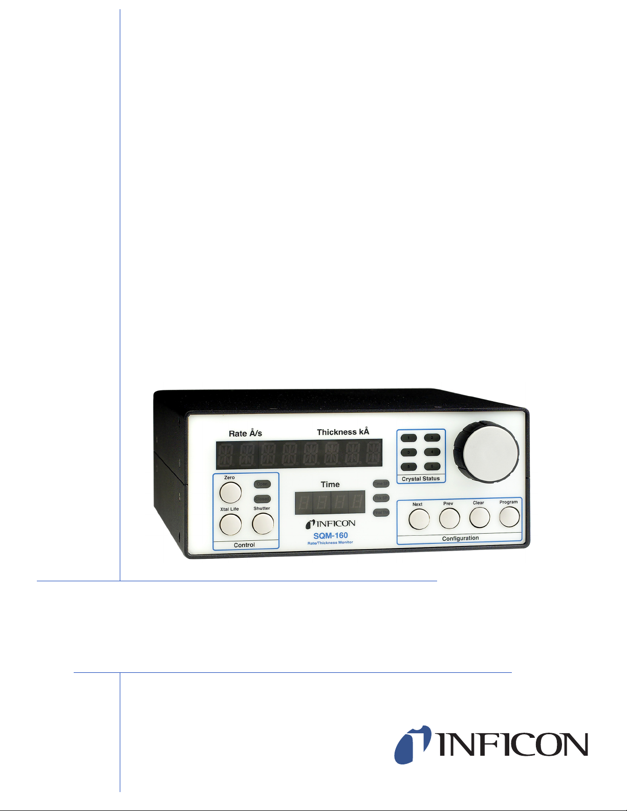
Figure 1-1 SQM-160 Multi-Film Rate/Thickness Monitor
SQM-160 Operating Manual
Chapter 1
Introduction
The SQM-160™ uses proven INFICON® quartz crystal sensor technology to
measure rate and thickness in a thin film deposition process. Two sensor inputs are
standard and four additional sensor inputs are optional. Two recorder outputs
provide analog rate and thickness signals.
Sensor inputs can be assigned to different materials, averaged for accurate
deposition control in large systems, or configured for a dual sensor. The rate
sampling mode allows a shuttered sensor to extend sensor life in high rate
processes. Rate displays of 0.1 Å/s or 0.01 Å/s are user selectable. In addition,
frequency or mass displays can be selected. Four relay outputs allow the SQM-160
to control source or sensor shutters, signal time and thickness setpoints, and signal
IPN 074-511-P1C
crystal failure. Digital inputs allow external signals to start/stop and zero readings.
The SQM-160 comes with an RS-232 port and Windows
®
software that allows
instrument setup from your computer. The software can be used to set and store
all parameters, operate the instrument, and save process data in an .txt file that can
easily be imported into Excel
®
. USB or Ethernet options add to the communications
flexibility.
1 - 1
Page 14
SQM-160 Operating Manual
CAUTION
WARNING
WARNING - Risk Of Electric Shock
1.1.1 Related Manuals
Sensors are covered in separate manuals. PDF files of these manuals are
contained in the 074-5000-G1 CD, part of the Ship Kit.
074-154 - Bakeable Sensor
074-156 - Front Load Sensor, Single/Dual
074-157 - Sputtering Sensor
147-800 - Cool Drawer Sensor, Single/Dual
1.2 Instrument Safety
1.2.1 Definition of Notes, Cautions and Warnings
When using this manual, please pay attention to the NOTES, CAUTIONS and
WARNINGS found throughout. For the purposes of this manual they are defined as
follows:
NOTE: Pertinent information that is useful in achieving maximum SQM-160
efficiency when followed.
Failure to heed these messages could result in damage
to the SQM-160.
Failure to heed these messages could result in personal
injury.
Dangerous voltages are present which could result in
personal injury.
IPN 074-511-P1C
1 - 2
Page 15

1.2.2 General Safety Information
WARNING - Risk Of Electric Shock
CAUTION
Do not open the SQM-160 case! There are no
user-serviceable components within the SQM-160 case.
Dangerous voltages may be present whenever the power
cord or external input/relay connectors are present.
Refer all maintenance to qualified personnel.
This SQM-160 contains delicate circuitry which is
susceptible to transient power line voltages. Disconnect
the line cord whenever making any interface
connections. Refer all maintenance to qualified
personnel.
SQM-160 Operating Manual
1.2.3 Earth Ground
The SQM-160 is connected to earth ground through a sealed three-core
(three-conductor) power cable, which must be plugged into a socket outlet with a
protective earth terminal. Extension cables must always have three conductors
including a protective earth terminal.
IPN 074-511-P1C
1 - 3
Page 16
SQM-160 Operating Manual
WARNING - Risk Of Electric Shock
WARNING
Never interrupt the protective earth circuit.
Any interruption of the protective earth circuit inside or outside the SQM-160,
or disconnection of the protective earth terminal is likely to make the SQM-160
dangerous.
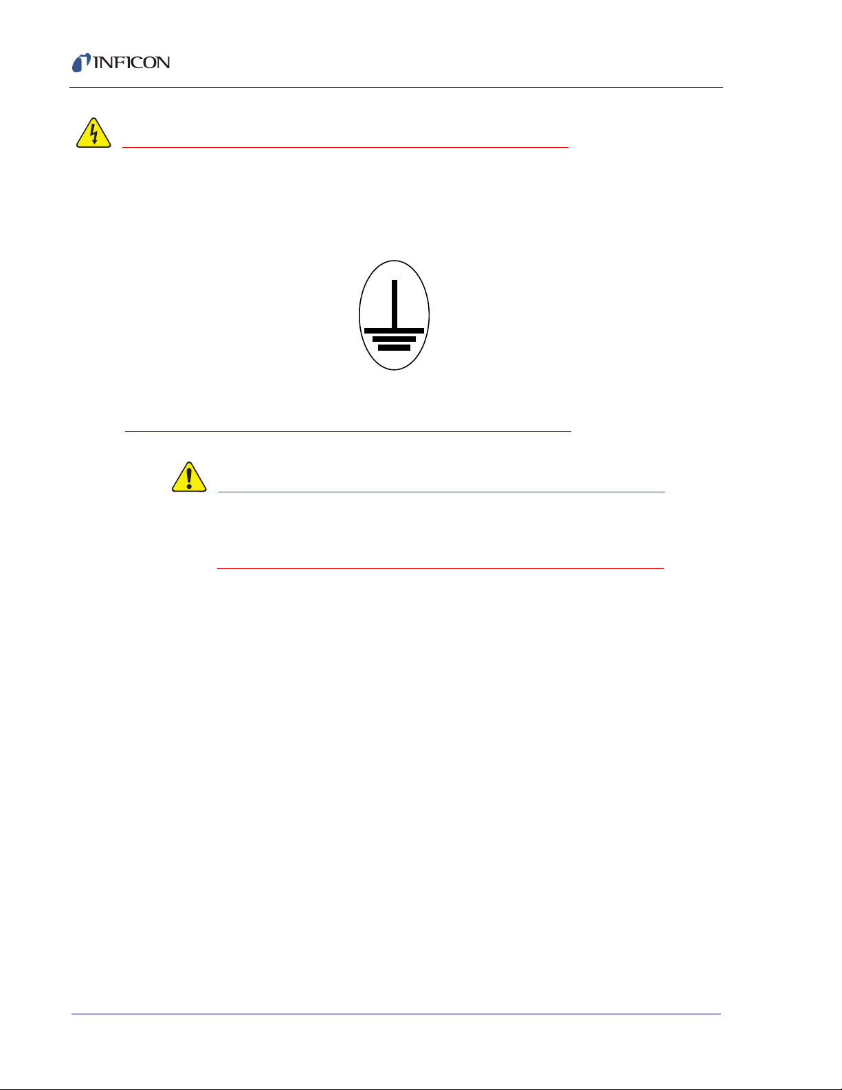
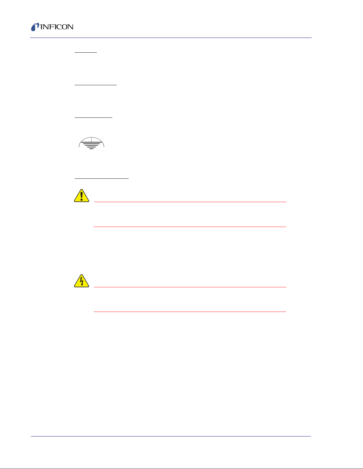
This symbol indicates where the protective earth ground is connected inside
the SQM-160. Never unscrew or loosen this connection.
There are no adjustments or user-serviceable parts
inside the SQM-160. For maintenance or repair, contact
INFICON.
1.3 How To Contact INFICON
Worldwide support information, to contact a:
Technical Support Engineer with questions regarding applications for and
programming the SQM-160
Service Engineer with questions regarding troubleshooting, diagnosing or
repairing a defective SQM-160
Sales and Customer Service, to contact the INFICON Sales office nearest you
Repair Service, to contact the INFICON Service Center nearest you
is available at the Support tab a www.inficon.com.
If you are experiencing a problem with your SQM-160, please have the following
information readily available:
the serial number and firmware version for your SQM-160,
a description of your problem,
IPN 074-511-P1C
an explanation of any corrective action that you may have already attempted,
and the exact wording of any error messages that you may have received.
To contact Customer Support, see Support at www.inficon.com.
1 - 4
Page 17

1.3.1 Returning Your SQM-160
Do not return any component of your SQM-160 to INFICON without first speaking
with a Customer Support Representative. You must obtain a Return Material
Authorization (RMA) number from the Customer Support Representative.
If you deliver a package to INFICON without an RMA number, your package will be
held and you will be contacted. This will result in delays in servicing your SQM-160.
Prior to being given an RMA number, you may be required to complete a
Declaration Of Contamination (DOC) form if your sensor has been exposed to
process materials. DOC forms must be approved by INFICON before an RMA
number is issued. INFICON may require that the sensor be sent to a designated
decontamination facility, not to the factory.
1.4 Specifications
1.4.1 Measurement
Number of Sensors . . . . . . . . . . . . . 2 standard, 4 additional optional
Sensor Frequency Range . . . . . . . . 4.0 MHz to 6.0 MHz
SQM-160 Operating Manual
Reference Frequency Accuracy . . . . 0.002%
Reference Frequency Stability . . . . . +/- 2ppm (total, 0 to 50°C)
Thickness Display Resolution . . . . . 1 Å
Frequency Resolution* . . . . . . . . . . . +/- 0.12 Hz (Std.), +/- 0.03 Hz (HiRes)
Rate Resolution* . . . . . . . . . . . . . . . 0.60 Å/s (Std.), 0.037 Å/s (HiRes)
Thickness Resolution* . . . . . . . . . . . 0.15 Å (Std.), 0.037 Å (HiRes)
*Density = 1, Period = 4 rdgs/sec (Std.) 10 rdgs/s (HiRes)
1.4.2 Film Parameters
IPN 074-511-P1C
Stored Films . . . . . . . . . . . . . . . . . . . 99
Density . . . . . . . . . . . . . . . . . . . . . . . 0.5 – 99.99 gm/cc
Tooling . . . . . . . . . . . . . . . . . . . . . . . 10 – 399 %
Z-Ratio . . . . . . . . . . . . . . . . . . . . . . . 0.10 – 10.00
Final Thickness . . . . . . . . . . . . . . . . 0.000 – 99.99 kÅ
Thickness Setpoint . . . . . . . . . . . . . . 0.000 – 99.99 kÅ
Time Setpoint . . . . . . . . . . . . . . . . . . 0:00 – 99:59 mm:ss
Sample/Hold. . . . . . . . . . . . . . . . . . . 0-9999 s
Sensor Average . . . . . . . . . . . . . . . . Any combination of installed sensors
1 - 5
Page 18

SQM-160 Operating Manual
1.4.3 System Parameters
Measurement Period . . . . . . . . . . . . 0.15 to 2 s
Simulate Mode . . . . . . . . . . . . . . . . . On/Off
Frequency Mode . . . . . . . . . . . . . . . On/Off
Rate Resolution . . . . . . . . . . . . . . . . 0.01/0.1 Å/s
Measurement Filter . . . . . . . . . . . . . 1 to 20 readings
Dual Crystal 1/2 . . . . . . . . . . . . . . . . On/Off
Rate Sampling . . . . . . . . . . . . . . . . . On/Off
RS-232 Baud Rate . . . . . . . . . . . . . . 2.4/4.8/9.6/19.2 kb/s
Etch Mode . . . . . . . . . . . . . . . . . . . . On/Off
Crystal Tooling 1-6 . . . . . . . . . . . . . . 10-399%
Crystal Fail Min/Max. . . . . . . . . . . . . 4.0 to 6.0 MHz / 4.1 to 6.1 MHz
1.4.4 Digital I/O
Digital Inputs. . . . . . . . . . . . . . . . . . . 4
Functions . . . . . . . . . . . . . . . . . . . . . Open Shutter, Close Shutter, Zero
Thickness, Zero Time
Input Rating . . . . . . . . . . . . . . . . . . . 5 V (dc), non-isolated
Relay Outputs. . . . . . . . . . . . . . . . . . 4
Functions . . . . . . . . . . . . . . . . . . . . . Shutter, Sample/Hold or Thickness Setpoint,
Dual Sensor Shutter or Time Setpoint,
Crystal Fail
Relay Rating. . . . . . . . . . . . . . . . . . . 30 V
or 30 V (dc), 2 A maximum
rms
IPN 074-511-P1C
1 - 6
Page 19

1.4.5 General Specifications
Mains Power Supply. . . . . . . . . . . . . 100-120/200-240~, ±10% nominal, 50/60 Hz
Power Consumption . . . . . . . . . . . . . 20 W
Operating Environment . . . . . . . . . . 0°C to 50°C
Storage Environment . . . . . . . . . . . . -40°C to 70°C
Rack Dimensions (HxWxD) . . . . . . . 88.5 mm x 212.7 mm x 196.9 mm
SQM-160 Operating Manual
0 to 80% RH non-condensing
0 to 2,000 meters
Indoor Use Only
Class 1 Equipment (Grounded Type)
Suitable for Continuous Operation
Ordinary Protection (not protected against
harmful ingress of moisture)
Pollution Degree 2
Installation (Overvoltage) Category II
for transient overvoltages
Weight . . . . . . . . . . . . . . . . . . . . . . . 2.7 kg (6 pounds)
IPN 074-511-P1C
1 - 7
Page 20
SQM-160 Operating Manual
1.5 Unpacking and Inspection
1 If the SQM-160 has not been removed from its packaging, do so now.
2 Carefully examine the unit for damage that may have occurred during shipping.
This is especially important if you notice obvious rough handling on the outside
of the container. Immediately report any damage to the carrier and to INFICON.
3 Do not discard the packing materials until you have taken inventory and have
at least performed a power on verification.
4 Take an inventory of your order by referring to your order invoice and the
information contained in section 1.6.
5 To install and setup, see Chapter 2, Quick Start.
6 For additional information or technical assistance, contact INFICON, refer to
section 1.3 on page 1-4.
1.6 Parts and Options Overview
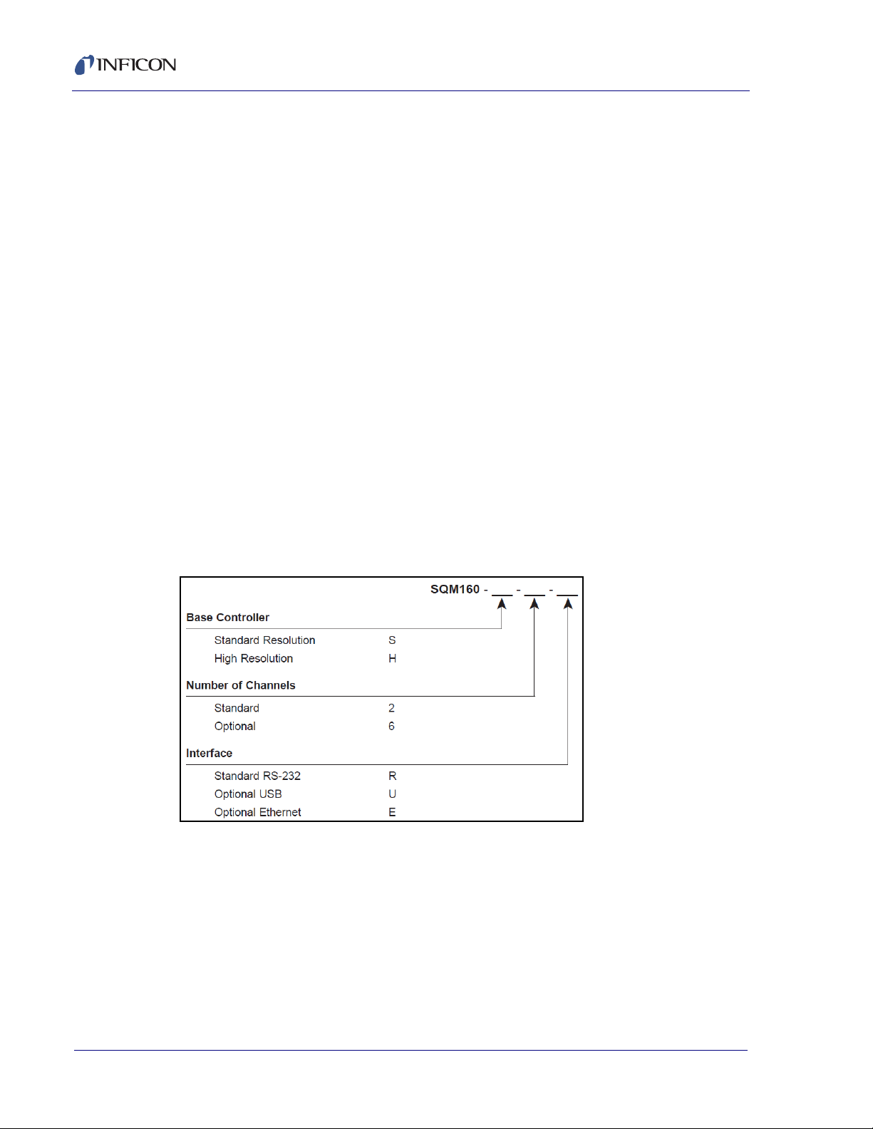
1.6.1 Base Configurations
SQM-160 . . . . . . . . . . . . . . . . . . . . . . . . .SQM160-X-X-X
Consult the figure below for possible configurations.
Figure 1-2 SQM-160 Configurations
Technical Manual . . . . . . . . . . . . . . . . . . .074-511 on 074-5000-G1 CD
IPN 074-511-P1C
1 - 8
Page 21

1.6.2 Accessories
Each sensor requires an oscillator kit to interface to the controller:
SQM-160 10 ft. Oscillator Kit . . . . . . 782-934-003-10
SQM-160 25 ft. Oscillator Kit . . . . . . 782-934-003-25
SQM-160 50 ft. Oscillator Kit . . . . . . 782-934-003-50
SQM-160 100 ft. Oscillator Kit . . . . . 782-934-003-99
Above kits consist of oscillator 782-900-010, 6 inch BNC oscillator to feedthrough
cable 782-902-011 and BNC controller to oscillator cable 782-902-012-10,
782-902-012-25, 782-902-012-50 or 782-902-012-99. These kits are designed for
use with the standard in-vacuum cables ranging in length from 6 in. (15.2 cm) to
36 in. (91.4 cm). The 007-044 standard in-vacuum cable supplied with the front
load style sensors are 30.75 in. (78.1 cm) long.
19 in. Rack mount for 1 SQM-160 . . 782-900-008
19 in. Rack mount for 2 SQM-160 . . 782-900-014
SQM-160 Operating Manual
1.6.3 Sensors
Front Load Single Sensor. . . . . . . . . . . . . . . . . . . . . SL-XXXXX
Front Load Dual Sensor . . . . . . . . . . . . . . . . . . . . . . DL-AXXX
Cool Drawer Single Sensor . . . . . . . . . . . . . . . . . . .CDS-XXFXX
Cool Drawer Dual Sensor. . . . . . . . . . . . . . . . . . . . . CDD-XFXX
Sputtering Sensor. . . . . . . . . . . . . . . . . . . . . . . . . . . 750-618-G1
Front Load UHV Bakeable Sensor . . . . . . . . . . . . . .BK-AXF
NOTE: "X" in part number indicates customer-selectable option, see
www.inficon.com for Sensor Datasheets.
NOTE: All shuttered sensors require a feedthrough with an air line and a
IPN 074-511-P1C
Pneumatic Shutter Actuator Control Valve . . . . . . . . 750-420-G1
NOTE: Multi-crystal (rotary) sensor should not be used with the SQM-160
pneumatic shutter actuator control valve.
1 - 9
Page 22

SQM-160 Operating Manual
This page is intentionally blank.
1 - 10
IPN 074-511-P1C
Page 23

2.1 Introduction
WARNING - Risk Of Electric Shock
WARNING - Risk Of Electric Shock
This section assumes you are familiar with thin film monitors. See section 2.3,
Front Panel, on page 2-2 and section 2.4, Rear Panel, on page 2-3 for basic system
use and connection information.
2.2 Installation
SQM-160 Operating Manual
Chapter 2
Quick Start
Maintain adequate insulation and physical separation of
sensor, I/O, and wiring from hazardous voltages.
1 Rack Installation
The SQM-160 occupies a 3.5 in. high, half-rack space. Rack installation
requires an optional half-rack adapter kit or a full rack extender kit. Install the
SQM-160 in a 19 in. rack with the appropriate hardware. See section 3.21,
Rack Mounting Procedure, on page 3-18, for detailed installation instructions.
2 Power Connection
Verify that the power cable provided is connected to a
properly grounded mains receptacle.
IPN 074-511-P1C
3 Sensor Connections
Connect the BNC cables and oscillator from your vacuum chamber
feedthrough to the SQM-160 Sensor Input(s). See section 2.4 on page 2-3.
4 Digital I/O Connections
Refer to section 3.20, I/O Connections, on page 3-16 for details on wiring digital
I/O to the SQM-160 Relay I/O connector.
5 Computer Connection
If you would like to use the supplied Windows Comm software with the
SQM-160, see section Chapter 4, SQM-160 Comm Software, on page 4-1.
2 - 1
Page 24
SQM-160 Operating Manual
Crystal Status
Thickness kA
Next
Clear Program
Open
Closed
Thk SP
1
2
Display 1
Display 2
Crystal
Status
LEDs
Control
Knob
Control
Section
Setpoint
LEDs
Configuration
Section
6 Option Connections
If you have purchased the optional four sensor card, connect the four additional
sensors to these four inputs.
7 Power On
Move the rear panel power switch to the On (|) position. The SQM-160 will
briefly display its software and hardware versions, then go to normal operating
mode.
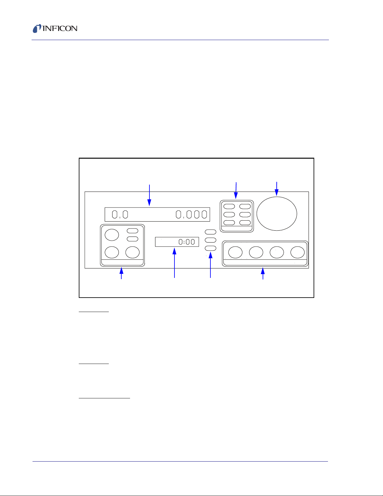
2.3 Front Panel
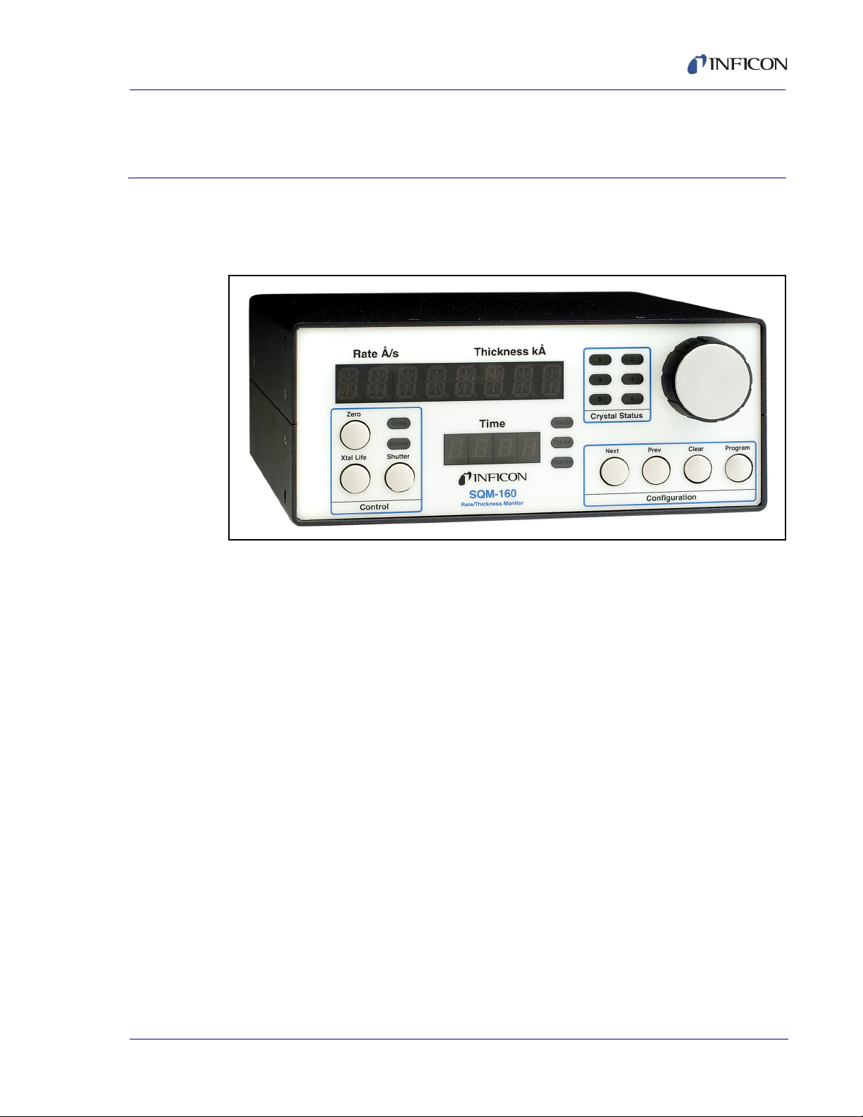
Figure 2-1 SQM-160 Front Panel
Rate A/s
Zero
Xtal Life Shutter
Time
Time SP
Final Thk
3
4
5
6
Prev
Display 1
Displays rate/thickness or frequency in normal operation. If multiple sensors are
being used and Display shows Time, this is the average of those sensors. Turn the
Control Knob right to display each individual sensor's readings. Displays the setup
parameter name in program mode.
Display 2
Displays deposition time, or the sensor # displayed on Display 1 when scrolling
through sensor readings. Displays setup parameter values in program mode.
Control Section
Push-button to zero the thickness reading.
Push-button to toggle display between Crystal Life and Rate/Thickness readings.
Push-button to Open/Close shutter relay.
Control Configuration
IPN 074-511-P1C
2 - 2
Two LED shutter relay status display.
Page 25
SQM-160 Operating Manual
Sensor 1 Sensor 2
Option Card
Relay I/O
100-120/200-240V~
Thick Out
Rate Out
3
456
Fuse T2.5A 250V
USB/Ethernet
Configuration Section
Push-button to enter/exit program mode.
Push-button to cancel a change and return to original value.
Push-buttons to move to Next/Previous parameter.
Setpoint LEDs
Illuminates when the indicated setpoint is reached.
Crystal Status LEDs
Illuminates when the crystal is active and operating properly.
Flashes when an active crystal fails.
Extinguished when that crystal is not being used.
Control Knob
Used to adjust values or scroll though menu selections.
Pushing the control knob stores the current setting.
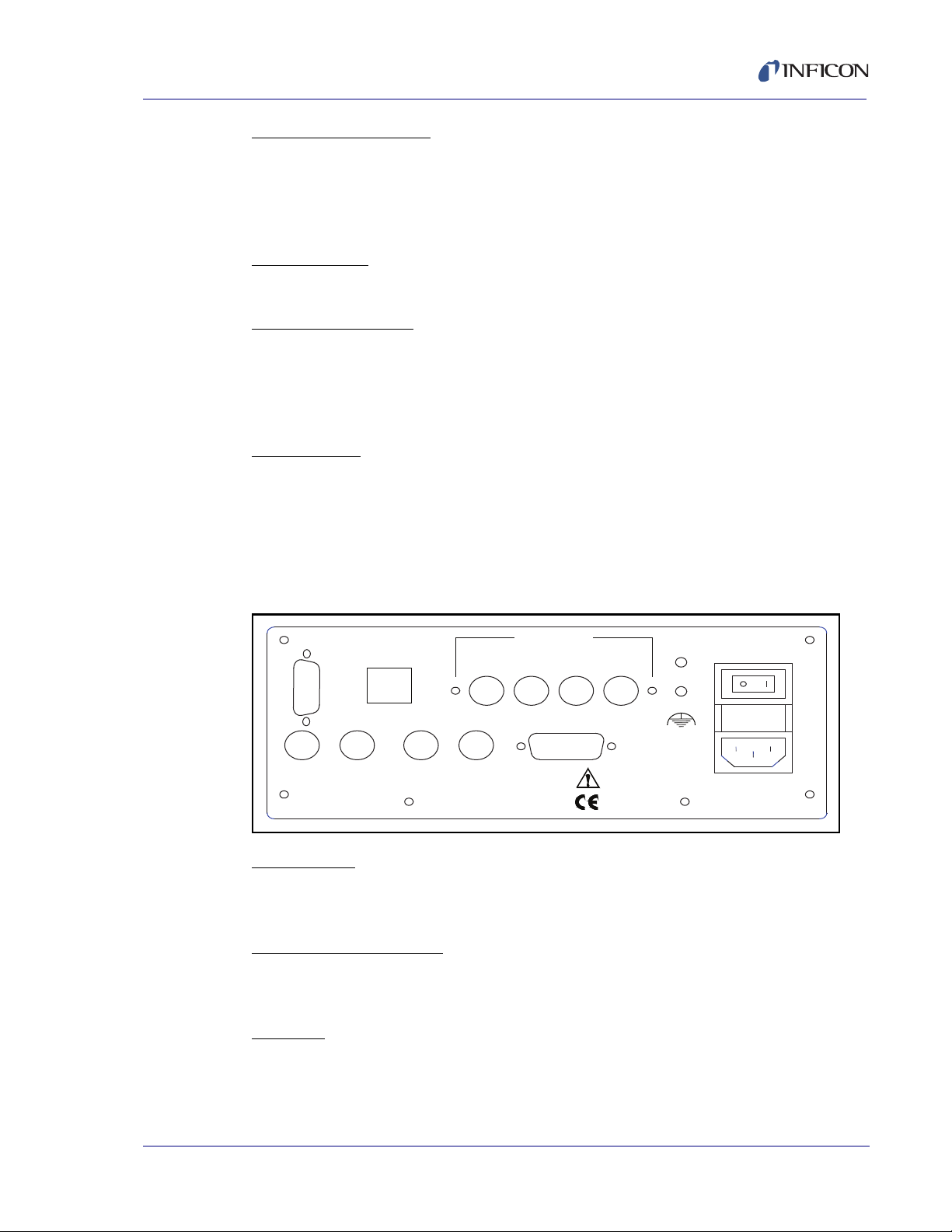
2.4 Rear Panel
Figure 2-2 Rear Panel
RS-232
IPN 074-511-P1C
Sensor 1 & 2
Connection to quartz crystal sensors. See section 2.5 on page 2-4 for detailed
hookup information.
Rate and Thick Outputs
Provides 0-5 V analog outputs for Sensor 1 & 2 rate and thickness readings. For
connection to strip chart recorders, etc.
Sensor
50/60 Hz
20 W
Relay I/O
Connects 4 relays and 4 digital inputs to external devices. See section 3.20, I/O
Connections, on page 3-16 for connections.
2 - 3
Page 26
SQM-160 Operating Manual
WARNING
WARNING - Risk Of Electric Shock
RS-232
Connection to computer for programming and data acquisition. See Chapter 5,
Communications.
USB/Ethernet
Optional connection to computer USB or Ethernet port for programming and data
acquisition. See Chapter 5, Communications.
Option Card
Provides four additional sensor measurement channels.
Measurement ground terminal useful for common system and cable grounding.
Power Connector
Use removable power cords only of the specified type
and rating, attached to a properly grounded receptacle.
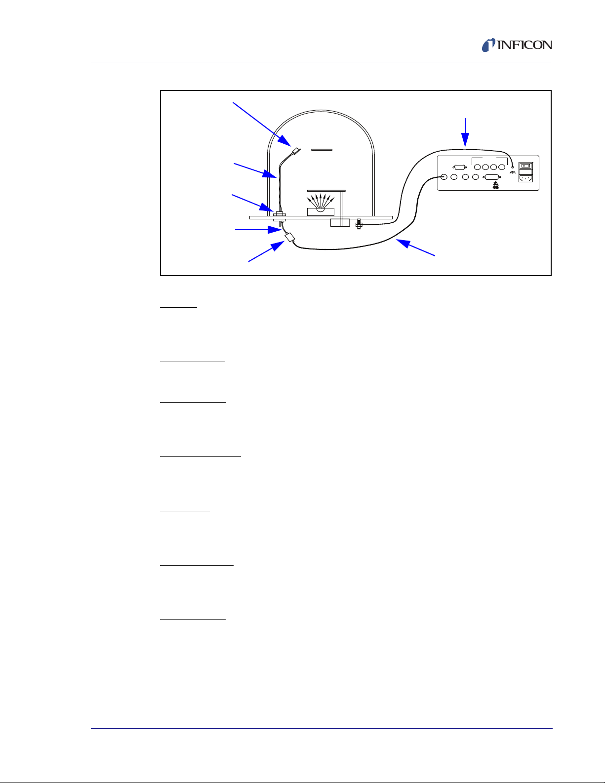
2.5 System Connections
Figure 2-3 shows typical vacuum system wiring.
WARNING: Maintain adequate insulation and physical
separation of sensor wiring from hazardous voltages.
IPN 074-511-P1C
2 - 4
Page 27
SQM-160 Operating Manual
Sensor
Relay I/O
Option Card
Rate OutThick OutSensor 2Sensor 1
RS-232 43
100-120/200-240V~
50/60 Hz
20 W
Fuse T2.5A 250V
65
Sensor
In-Vac Cable
Feedthrough
6 in. BNC Cable
Oscillator
10 ft. BNC Cable
Ground Wire
SQM-160 Monitor
Figure 2-3 Typical Vacuum System Wiring
Sensor
Holds the quartz crystal used to measure rate and thickness. Crystals must be
replaced occasionally.
IPN 074-511-P1C
In-Vac Cable
Microdot cable that connects the sensor to the feedthrough.
Feedthrough
Provides isolation between vacuum and atmosphere for electrical and cooling
lines.
6 in. BNC Cable
Provides a flexible connection from the feedthrough to the oscillator. Keep this
cable as short as possible.
Oscillator
Contains the electronics to operate the quartz crystal. The length from the oscillator
to the crystal should be under 40 in. (1 m).
10' BNC Cable
Connects the oscillator to the SQM-160. Lengths up to 100 ft. (30 m) are
acceptable.
Ground Wire
A wire, preferably braided, that connects the vacuum system to the SQM-160
ground terminal.
2 - 5
Page 28

SQM-160 Operating Manual
2.6 Film Setup
This section will help you set up the SQM-160 to measure a film. See Chapter 3,
Operation, for detailed programming instructions.
1 Enter Program Mode
Press Program to enter the film setup menu. If the Crystal Life display is shown,
press Xtal Life to return to Rate/Thickness mode, then press Program.
2 Select a Film
Turn the Control Knob to select one of the 99 possible films, then press the
Control Knob to enter that Film Menu.
3 Set Film Parameters
Turn the Control Knob to set the first film parameter (Density). The parameter
value is shown in Display 2. Press the Control Knob to save the value and move
to the next parameter. Press Clear to return the film parameter to its original
value. Continue to set each parameter. Be sure to press the Control Knob to
store each parameter. Press Program to exit Program mode and return to
normal mode.
4 Set System Parameters
To Enter the System Menu, press Program, then Prev. Select and set system
parameters by turning and then pressing the Control Knob as described above.
Press Program to return to Normal mode.
If the sensor(s) selected during Film setup are connected properly to the SQM-160,
the Crystal Status LEDs should be illuminated. If not, return to the Film Menu and
set the Sensor Average parameter to the desired sensor(s). See section 3.5 on
page 3-6 for detailed information on assigning sensors to a film.
If the Crystal Status LED is flashing, the sensor is most likely not properly
connected. A small test crystal, supplied with each oscillator module, can be used
to test sensor connections external to the vacuum chamber. To use the test crystal,
disconnect the oscillator from its 6 in. BNC cable. Attach the test crystal to the
oscillator's feedthrough connector. The Crystal Status LED will remain illuminated
if the external sensor connections are correct.
See section 6.2.2, Troubleshooting Sensors, on page 6-3 for assistance in
troubleshooting sensor problems.
IPN 074-511-P1C
2 - 6
Page 29

2.7 Depositing a Film
If you have followed this Quick Start chapter, you are ready to deposit a film. Follow
the procedure below to begin deposition.
1 Verify Sensor Operation
Verify that the Crystal Status LED for the measuring sensor(s) is illuminated,
and not blinking.
2 Display Rate/Thickness
Display 1 should be displaying Rate on the left and Thickness on the right. If
the Crystal Life display mode is active, press the Xtal Life switch to return to
Rate/Thickness mode. If the Program Mode is active, press Program to return
to normal mode.
3 Zero Thickness
If needed, press the Zero switch to zero the thickness reading.
4 Start Deposition
Apply power to the source evaporation supply. If the SQM-160 shutter relay is
connected, press the Shutter switch to open the source shutter and begin
deposition.
SQM-160 Operating Manual
Rate and Thickness displays should begin to move from zero.
If the displays remain at zero, check the system setup to assure that evaporating
is actually taking place. Also check that the deposited material is reaching the
sensor.
If the display is erratic or noisy, first check your sensor connections. See section
6.2.2, Troubleshooting Sensors, on page 6-3 for information that can help in
identifying the cause of noisy readings.
If the rate and thickness readings do not match expectations, see the Film
Parameter (Density, Z-Ratio (Z-Factor), Tooling) and Sensor Tooling sections of
IPN 074-511-P1C
Chapter 3.
Review the remainder of this manual for detailed operational, programming, and
safety information.
2 - 7
Page 30

SQM-160 Operating Manual
This page is intentionally blank.
2 - 8
IPN 074-511-P1C
Page 31

3.1 Introduction
Crystal Status
Thickness kA
Next
Clear Program
Open
Closed
Thk SP
1
2
Press Next to
move through the
Film menu
Press Prev then
Next to move through
the System menu
Press
Program
to access
menus
Display 1
Display 2
This chapter details the operation of the SQM-160 menus and front panel controls.
3.2 Menu Selection
Two menus provide control of the SQM-160 programming. The Film Menu
customizes each stored film. The System Menu sets values that remain constant
for all films.
The Configuration section of the SQM-160 front panel contains four switches used
to access the program menus. Within the program menus, the Control Knob is also
used to adjust values and select menu choices. In program mode, Display 1 shows
the parameter to be changed. Display 2 shows the selected parameter's value.
SQM-160 Operating Manual
Chapter 3
Operation
NOTE: If Crystal Life is shown on the SQM-160 displays, press the Xtal Life
switches to return the displays to normal rate/thickness or frequency
display.
To enter the Film Menu, press Program. The SQM-160 displays the currently
selected film. If desired, turn, then press, the Control Knob to select a different film.
Press Next to display the first parameter for the selected film.
To enter the System Menu, press Program then press Prev.
Figure 3-1 SQM-160 Front Panel
Rate A/s
IPN 074-511-P1C
Zero
Time
Xtal Life Shutter
Control Configuration
Time SP
Final Thk
3
4
5
6
Prev
3 - 1
Page 32

SQM-160 Operating Manual
Program
Film 1
Film 99
- DENSITY
- TOOLING
- Z-FACTOR
- FINL THK
- THK SET *
- TIME SET *
- SAMPLE *
- HOLD *
- SENS AVG *
- 1
- 2
- 3
- 6
Sensors 3 - 6
show only if the
four-sensor
option card is
installed
Film Selection
Film Parameters Menu Sub-Menu
NOTE: Depending on System Menu setup, selections marked with a *
may not be available. See Table 3-1.
3.3 Film Menu
The Film Menu programs the SQM-160 for the materials that will be deposited.
Ninety-nine films can be stored, but only one film is active at any time.
1 Press Program to enter program mode.
2 Use the Control Knob to scroll to the desired Film # (1-99).
3 Press the Control Knob or Next to enter the film parameters for the selected
film.
4 Use Next and Prev to move through the film parameters, shown in Display 1
(refer to Figure 3-1).
5 Use the Control Knob to adjust the parameter value, shown in Display 2 (refer
to Figure 3-1), to the desired setting.
6 Press the Control Knob or Next to save the displayed value and move to the
next material parameter. Press Clear to abandon the change and return to the
original setting.
7 Press Program to exit the Film Menu and return to normal mode.
Figure 3-2 and Table 3-1 detail the parameters available in the Film Menu. Refer
to later sections of this chapter for instructions on setting specific film parameters.
Figure 3-2 Film Menu Parameters
IPN 074-511-P1C
3 - 2
Page 33

SQM-160 Operating Manual
Table 3-1 Film Menu
Display Description Range Default Units
DENSITY Density of the material being deposited.
Consult the Appendix A for common material
densities.
TOOLING Overall Tooling Factor for this film. See
section 3.7 on page 3-8.
Z-FACTOR
(Z-Ratio)
Z-Factor of the material being deposited.
See Appendix A for common material
Z-Factors.
FINL THK Desired Final Thickness of deposited
material. Illuminates Final Thk LED when
reached.
THK SET Thickness value that closes the Thickness
Setpoint relay and illuminates Thk SP LED.
Not available when Sampling is ON in
System Menu.
TIME SET Elapsed time that closes the Timer Setpoint
relay and illuminates Time SP LED. Not
available when Relay 2 is set to Dual or
Sensor 2 in the System Menu.
SAMPLE The time for the sensor shutter to remain
open when Rate Sampling is enabled in the
System Menu. Not available when Sampling
is OFF in System Menu.
0.5 – 99.99 1.00 gm/cc
10 – 399 100 %
0.10 – 10.00 1.0
0.000 – 99.99 0.500 kÅ
0.000 – 99.99 0 kÅ
0:00 – 99:59 0 Min:
Sec
0 - 9999 0 Sec
HOLD The time for the sensor shutter to remain
0 - 9999 0 Sec
closed when Rate Sampling is enabled in the
System Menu. Not available when Sampling
is OFF in System Menu.
SENS AVG Enable/disable crystals for this film. See the
IPN 074-511-P1C
Sensor Selection section of this chapter. Not
Enabled/
Disabled
Ch1
Enabled
available when Relay 2 is set to Dual in the
System Menu.
3 - 3
Page 34

SQM-160 Operating Manual
Program Prev
- TIMEBASE
- SIM MODE
- DISPLAY
- RATE RES
- RATEFILT
- RELAY 2
- SAMPLING
- BAUDRATE
- ETCH
- xTOOLING
- RELAYS
- FM IN/MAX
- R/T BNDS
- THCK (A)
- THCK(Nm)
- MASS
- FREQ
- TIME SP
- DUAL
- SENS 2
- FREQ MIN
- FREQ MAX
- xTLTOOL1
- xTLTOOL6
- RELAY 1
- RELAY 4
System Parameters Menu
Sub-Menu
- RATE MIN
- RATE MAX
- THICKMIN
- THICKMAX
3.4 System Menu
The System Menu sets values that pertain to the overall functions of the SQM-160
and to the vacuum system's setup. System Menu parameters apply to all films.
1 Press Program to enter program mode.
2 Press Prev to enter the System Menu.
3 Use Next and Prev to move through the system parameters.
4 Use the Control Knob to adjust the parameter value shown in Display 2 to the
desired setting.
5 Press the Control Knob or Next to save the displayed value and move to the
next material parameter. Press Clear to abandon the change and return to the
original setting.
6 Press Program to exit the System Menu and return to normal mode.
Figure 3-3 System Parameters Menu
Table 3-2 System Menu
Display Description Range Default Units
TIMEBASE Time required for a measurement.
SIM MODE Simulates sensor inputs. On/Off Off
DISPLAY Selects Rate/Thickness in Angstroms,
RATE RES Sets rate resolution to 0.01 or
3 - 4
Longer times yield higher accuracy.
Rate/Thickness in Nanometers, Frequency,
or Mass (ugm/cc) display.
0.1 Å/s. Hi/Low Low
0.15 – 2.00 0.25 Sec.
THCK/nÅnM/FRE
Q/MASS
IPN 074-511-P1C
Rate
Page 35

SQM-160 Operating Manual
Table 3-2 System Menu (continued)
Display Description Range Default Units
RATEFILT Number of rate readings averaged. 1 – 20 8
RELAY 2 Select Timer to cause relay to close when
On/Off Timer
time setpoint is reached. Dual causes relay
to close (to activate dual sensor) when
sensor 1 fails. Sensor 2 causes relay to
activate a sensor shutter when Sensor 2 is
assigned to a film.
SAMPLING When Sampling is ON the sensor shutter
On/Off Off
periodically “samples” the rate. After a
period, the shutter closes and the SQM-160
“holds” the same rate reading until the next
sample period. Sample and Hold times are
set in the Film Menu.
BAUDRATE Serial baud rate to PC. 2.4 – 19.2 19.2 kbps
ETCH Sets rate negative for etching. On/Off Off
xTOOLING Tooling value assigned to each sensor. See
10 – 399 100 %
the Sensor Tooling section of this chapter.
RELAYS Assigns normally open or normally closed
NO/NC NO
operation for each relay. Note: All relays are
open with power off.
FMIN/MAX Sub-menu sets minimum and maximum
4.00 – 6.00
5.00
MHz
crystal frequencies.
4.10-6.10
6.10
R/T BNDS Rate and Thickness Bounds sub-menu for
analog outputs.
RATE MIN Deposition Rate for zero output (zero Volts). 0 – 999 0 Å/s
IPN 074-511-P1C
Volts).
THICKMIN Thickness for zero output
RATE MAX Deposition Rate for full scale output (+5
9.9 – 999 100 Å/s
0 – 99.99 0.00 kÅ
(zero Volts).
THICKMAX Thickness for full scale output
0 – 99.99 1.00 kÅ
(+5 Volts).
3 - 5
Page 36

SQM-160 Operating Manual
3.5 Sensor Selection
The SQM-160 comes standard with two sensor inputs. Four additional sensors are
available by adding a Sensor Option Card. A specific sensor can be assigned to
each film, or multiple sensors can be averaged for a film. The averaging option
provides more uniform coverage of the deposition area and provides a backup
sensor capability. If one of multiple sensors assigned to a film fails, the sensor is
automatically removed from rate/thickness calculations.
NOTE: If Relay 2 Dual is selected in the System Menu, Sensors 1 and 2 are set
up as a primary/secondary sensor pair. In that case, sensor averaging is
disabled. See section 3.12 on page 3-10 for information on dual sensors.
To assign a sensor, or sensors, to a film:
1 Press Program to enter Program mode.
2 Use the Control Knob to scroll to the desired Film # (1-9).
3 Press the Control Knob or Next to enter the film parameters for the selected
film.
4 Press Next until SENS AVG is shown.
5 Use the Control Knob to scroll through the sensors in Display 2.
6 Press the Control Knob to toggle the sensor on/off.
Sensor status can be seen by observing the Crystal Status LEDs:
If the LED is not illuminated, the crystal is disabled.
If the LED is illuminated, the crystal is enabled and receiving valid readings.
If the LED is blinking, the crystal is enabled, but is not receiving valid
readings.
7 Continue selecting sensors until the Crystal Status LEDs indicate the desired
setup.
8 Press Program to exit the Film Menu and return to normal mode.
9 Turn the Control Knob to sequence though each sensor's reading on Display 1.
When a single number is shown in Display 2 it is the sensor number whose
readings are shown in Display 1. When time is shown in Display 2, Display 1
shows the average of all assigned sensors.
IPN 074-511-P1C
3 - 6
Page 37

3.6 Sensor Frequency
Sensor Min/Max frequencies establish the operating range for the sensing quartz
crystals. Both values are used to determine the % life that is displayed in Xtal Life
mode.
When the sensor frequency drops below the minimum (or reads above the
maximum), the SQM-160 indicates a sensor failure by blinking the Crystal Status
display.
To set sensor minimum and maximum frequencies:
1 Press Program to enter Program mode.
2 Press Prev to enter the System Menu.
3 Press Next until FMIN/FMAX is shown.
4 Press the Control Knob to display FREQ MIN.
5 Adjust the Control Knob to the desired minimum operating frequency on
Display 2.
6 Press the Control Knob to accept the minimum value and display FREQ MAX.
SQM-160 Operating Manual
7 Adjust the Control Knob to the desired maximum operating frequency on
Display 2.
8 Press the Control Knob to accept the maximum value.
9 Press Program to exit the System Menu and return to normal mode.
Crystals sometimes fail unexpectedly, or exhibit erratic frequency shifts (mode
hopping) before total failure. Depending on the material, crystals may fail well
before the typical 5 MHz minimum. If you find that crystals fail early consistently,
set FREQ MIN to a value higher than 5 MHz to provide a Crystal Life warning
consistent with actual failure.
A sensor crystal with an initial value that exceeds the maximum will also cause a
blinking Crystal status. The maximum frequency can be set slightly above the
IPN 074-511-P1C
nominal values with no effect on accuracy.
3 - 7
Page 38

SQM-160 Operating Manual
Tooling
Over 100%
Tooling
Under 100%
Substrate
Substrate
3.7 Sensor Tooling
Sensor Tooling adjusts for the difference in deposition rate between the sensor and
the substrate being coated. It is an empirically determined value that matches the
sensor readings to the vacuum system.
Figure 3-4 Sensor Tooling
xTooling is set in the System Menu. It adjusts the tooling for each individual sensor
before it is averaged. xTooling for a sensor applies to all films. If the individual
sensor xToolings are set properly, a sensor failure will not cause a jump in the
average Rate and Thickness reading. See section 7.3, Determining Tooling, on
page 7-2 for more details.
To adjust xTooling:
1 Press Program to enter Program mode.
2 Press Prev to enter the System Menu.
3 Press Next until xTOOLING is shown, then press the Control Knob.
4 Adjust the Control Knob to set the XTLTOOL 1 value. Press the Control Knob
to save the value and move to XTLTOOL 2.
5 Repeat Step 4 for each of the installed sensors.
6 Press Program to exit the System Menu and return to normal mode.
Film Tooling is set in the Film Menu and is applied to the averaged Rate and
Thickness for all sensors assigned to that film. Film Tooling is a film-specific value,
and is seldom required.
IPN 074-511-P1C
3 - 8
Page 39

3.8 Display Units
The SQM-160 can display crystal measurements in several different units. To
select the display units:
1 Press Program to enter Program mode.
2 Press Prev to enter the System Menu.
3 Press Next until DSP..... is shown.
4 Turn the Control Knob left or right to select the desired display mode:
THCK — Rate in Å/s, Thickness in kÅ
nAnM — Rate in nM/s, Thickness in µM
MASS — Rate in ng/cc/s, Mass in µg (micrograms)
FREQ — Frequency in Hz
NOTE: When Nanometers is selected a small "n" appears between the rate
SQM-160 Operating Manual
and thickness displays. When Mass is selected a small "m" appears
between the rate and thickness displays.
5 Press the Control Knob to accept the choice.
6 Press Program to exit the System Menu and return to normal mode.
3.9 Crystal Life
The SQM-160 calculates the remaining crystal life based on the FMin/Max values
set in the System Menu (refer to section 3.4 on page 3-4).
To display the remaining crystal life for the sensors used by the currently active film:
1 Press the Xtal Life switch in the front panel Control section.
2 The sensor is shown in Display 1 and the % remaining life is shown in Display 2.
3 Turn the Control Knob to display the % life of other sensors active for this film.
IPN 074-511-P1C
4 Press Xtal Life again to return to normal rate/thickness, or frequency display.
NOTE: You cannot enter program mode while the crystal life display is active.
3.10 Zero Thickness
Before starting each film deposition, reset the SQM-160 Thickness value to zero.
To zero Thickness, press the Zero switch in the front panel Control section.
In addition to zeroing Thickness, pressing the Zero switch has these effects:
The Time display is reset to its programmed value and starts counting down.
The Thickness Setpoint and Timer relays open.
The Time SP, Thk SP, and Final Thk LEDs extinguish.
3 - 9
Page 40

SQM-160 Operating Manual
3.11 Shutter Operation
The SQM-160 Shutter switch controls a relay that is normally connected to the
source shutter.
To open or close the Shutter relay, press the Shutter switch in the front panel
Control section.
The Open and Closed LEDs illuminate to indicate the shutter status.
NOTE: If Relay 2 is set to Sensor 2 in System Menu, the operation of the Shutter
switch/relay changes slightly. In this case, the shutter relay will activate
only if Sensor 1 is assigned to the active film. If sensor 2 is assigned to the
active film, Relay 2 will close instead.
3.12 Dual Sensors
Dual shuttered sensors provide a backup (secondary) sensor in case of primary
sensor failure. When Relay 2 is programmed for Dual sensors in the System menu,
the SQM-160 will automatically switch to Sensor 2 when Sensor 1 readings stop or
become erratic.
To program the SQM-160 for dual sensors:
1 Press Program to enter Program mode.
2 Press Prev to enter the System Menu.
3 Press Next until RELAY 2 is shown.
4 Turn the Control Knob right to select DUAL sensor function.
5 Press the Control Knob to accept the value.
6 Press Program to exit the System Menu and return to normal mode.
7 In the film menu, assign only Sensor 1 to the film. The backup sensor 2 is
automatically assigned internally.
NOTE: Relay 2 is a multi-function relay. It can be programmed as a dual sensor
shutter, or to close when a programmed time has elapsed, or as a sensor
2 shutter relay. section 3.20, I/O Connections, on page 3-16 discuss the
other Relay 2 functions.
IPN 074-511-P1C
3 - 10
Page 41

3.13 Rate Sampling
In Rate Sampling mode, the SQM-160 opens a sensor shutter for a fixed time to
"sample" the process rate, then closes the shutter and "holds" the last rate reading
for a fixed time. While the shutter is closed (hold mode), the SQM-160 calculates
thickness based on the last sampled rate.
NOTE: Rate sampling can significantly extend crystal life in a high deposition rate
process. However, unless the process is very stable, the thickness
calculation during hold mode may be incorrect. Do not use rate sampling
if your rate varies during deposition.
To program the SQM-160 for Rate Sampling:
1 Press Program to enter Program mode.
2 Press Prev to enter the System Menu.
3 Press Next until SAMPLING is shown.
4 Turn the Control Knob right to turn ON rate sampling. Press the Control Knob
to accept the value.
SQM-160 Operating Manual
5 Press Program to exit the System Menu and return to normal mode.
6 Press Program to re-enter Program mode.
7 Use the Control Knob to scroll to the desired Film # (1-9), then press the Control
Knob or Next to enter the film parameter menu for the selected film.
8 Press Next until SAMPLE is shown.
9 Use the Control Knob to set the sample time period. Press the Control Knob to
accept the sample value and display HOLD.
10 Use the Control Knob to set the hold time period. Press the Control Knob to
accept the Hold value.
11 Press Program to exit the Film Menu and return to normal mode.
IPN 074-511-P1C
NOTE: The rate sampling relay is a dual function relay. It can be programmed
either to sample rate or to close when a programmed thickness is reached.
See section 3.15, Thickness Setpoint, on page 3-13. See 3.20, Operation,
for relay wiring.
3 - 11
Page 42

SQM-160 Operating Manual
3.14 Time Setpoint
The Time Setpoint provides a convenient way to signal a timed event. After a
pre-programmed time period, the Time Setpoint closes a relay when the Zero
switch is pressed.
To program the Time Setpoint:
1 Press Program to enter Program mode.
2 Press Prev to enter the System Menu.
3 Press Next until RELAY 2 is shown.
4 Turn the Control Knob right to select TIME. Press the Control Knob to accept
the value.
5 Press Program to exit the System Menu and return to normal mode.
6 Press Program to re-enter Program mode.
7 Use the Control Knob to scroll to the desired Film # (1-9), then press the Control
Knob or Next to enter the Film Parameter menu for the selected film.
8 Press Next until TIME SET is shown.
9 Use the Control Knob to set the timer setpoint. Press the Control Knob to
accept the value.
10 Press Program to exit the Film Menu and return to normal mode.
11 Press Zero to open the relay and begin counting down the Time Setpoint. When
the time reaches zero, the Time SP LED illuminates and the relay closes.
NOTE: Relay 2 is a multi-function relay. It can be programmed as a dual sensor
shutter, or to close when a programmed time has elapsed, or as a sensor
2 shutter relay. See section 3.11, Shutter Operation, on page 3-10 and
section 3.12, Dual Sensors, on page 3-10 for a discussion of other
Relay 2 functions.
IPN 074-511-P1C
3 - 12
Page 43

3.15 Thickness Setpoint
The Thickness Setpoint closes a relay when a programmed thickness is reached.
This setpoint is independent from Final Thickness, which always closes the source
shutter.
To program the Thickness Setpoint:
1 Press Program to enter Program mode.
2 Press Prev to enter the System Menu.
3 Press Next until SAMPLING is shown.
4 Turn the Control Knob right to turn OFF the Sampling function. Press the
Control Knob to accept the value.
5 Press Program to exit the System Menu and return to normal mode.
6 Press Program to re-enter Program mode.
7 Use the Control Knob to scroll to the desired Film # (1-9), then press the Control
Knob or Next to enter the Film Parameter menu for the selected film.
SQM-160 Operating Manual
8 Press Next until THK SET is shown, not FINL THK.
9 Use the Control Knob to set the thickness setpoint. Press the Control Knob to
accept the value.
10 Press Program to exit the Film Menu and return to normal mode.
When the Thickness Setpoint is reached, the Thk SP LED lights and the relay
closes. Use the Zero switch to open the relay and zero thickness at any time.
NOTE: The Thickness Setpoint relay is a dual function relay. It can be
programmed either to indicate a thickness, or to control a sensor shutter
for rate sampling. See section 3.13, Rate Sampling, on page 3-11. See
Chapter 4 for relay wiring.
IPN 074-511-P1C
3 - 13
Page 44

SQM-160 Operating Manual
CAUTION
3.16 Simulate Mode
In Simulate mode, the SQM-160 simulates attached sensors. It is an easy way to
become familiar with the SQM-160 front panel controls and programming. You can
open/close the shutter to simulate deposition, zero readings, and display crystal
life. You can also test the Time and Thickness setpoint relays and LEDs.
To enter Simulate mode:
1 Press Program to enter Program mode.
2 Press Prev to enter the System Menu.
3 Press Next until SIM MODE is shown.
4 Turn the Control Knob left or right to enable and disable Simulate mode.
5 Press the Control Knob to accept the value.
6 Press Program to exit the System Menu and return to normal mode.
3.17 Defaulting the Memory
Performing this procedure wil default the SQM-160 to its
factory setting. All Parameters set by the user will be
deleted. Do not perform this procedure until you have
created a back up database file using SQM160 Comm.
1 Power cycle the unit while pressing and holding select buttons until an error
message appears.
1a For firmware versions before v4.10 (clears only Film parameters):
Press and hold the ZERO + XTAL LIFE + SHUTTER buttons while powering up
the SQM-160.
1b For firmware version v4.10 and higher (clears Film and System parameters):
Press and hold the ZERO + XTAL LIFE + SHUTTER + CONTROL KNOB
buttons while powering up the SQM-160.
2 "ERROR 00" message should appear. Power cycle again and no error
messages should appear.
IPN 074-511-P1C
3 - 14
Page 45

3.18 Relay Operation
The four relays of the SQM-160 are physically single-pole, normally-open
(1FormA) relays. However, each can be programmed to act as either
normally-open or normally-closed during SQM-160 operation. It is important to
keep in mind that all relays will open if the SQM-160 is turned off or loses power.
See section 3.20 on page 3-16 for relay wiring.
To set the relay operating mode:
1 Press Program to enter Program mode.
2 Press Prev to enter the System Menu.
3 Press Next until RELAYS is shown and then press the Control Knob to display
Relay 1.
4 Turn the Control Knob left or right to select NO (normally open) or NC (normally
closed). Press the Control Knob to accept the value and display the next relay.
5 Repeat Step 4 for each of the four relays.
6 Press Program to exit the System Menu and return to normal mode.
SQM-160 Operating Manual
IPN 074-511-P1C
3 - 15
Page 46

SQM-160 Operating Manual
1
8
915
3.19 Analog Output Configuration
The SQM-160 analog outputs must be set to match the device that will be attached
to the Rate or Thickness output.
To set up the analog outputs in the System Menu:
1 Press Program to enter Program mode.
2 Press Prev to enter the System Menu.
3 Use Next to move through the system parameters until R/T BNDS is displayed.
4 Press the Control Knob to display RATE MIN.
5 Adjust the Control Knob to the Rate desired for a 0 V output.
6 Press the Control Knob to save the value and display the RATE MAX setting.
7 Adjust the Control Knob to the Rate desired for a 5 V output.
8 Press the Control Knob to save the value and display the THICK MIN setting.
9 Repeat steps 5-8 to adjust the Thickness output values.
10 Press Program to exit the System Menu and return to normal mode.
Refer to section 3.4 on page 3-4 for more information on setting SQM-160 System
parameters.
3.20 I/O Connections
A 15-pin female D-sub connector is included with the instrument to connect digital
I/O to the SQM-160 Relay I/O connector. The figure below shows the solder-side
pin assignments for the supplied connector.
Figure 3-5 Relay I/O Connector Rear View
IPN 074-511-P1C
3 - 16
Page 47

WARNING
WARNING
Table 3-3 Relay I/O Connections
SQM-160 Operating Manual
Pins
1,2
Relay 1
3,4
Relay 2
5,6
Relay 3
7,8
Relay 4
9 Zero Timer
10 Zero Thick
Function Description
Crystal Fail Relay Contacts close when all enabled sensors have failed.
Time Setpoint, Dual
Sensor, or Sensor 2
Relay
Shutter
Relay
Sampling or
Thickness Setpoint
Input
Input
If Relay 2 is set to TIME in the System menu, contacts close when
timer counts down to zero from its programmed Timer Setpoint value.
If DUAL is selected, contacts close when Sensor 1 fails. If SENS2 is
selected, contacts close when shutter is pushed if Sensor 2 is
programmed for the active film.
Controlled by front panel shutter switch. Contacts close when Shutter
Open is selected. If SENS2 is selected for Relay 2 in the System
menu, the shutter relay contacts close only if Sensor 1 is programmed
for the active film.
If Sampling is ON in System Menu, contacts close during Sample,
open during Hold. If Sampling is OFF contacts close when Thickness
Setpoint is reached.
Grounding this pin zeroes the setpoint timer.
Grounding this pin zeroes the thickness display.
11 Close Shutter Input Grounding this pin opens the shutter relay.
12 Open Shutter Input Grounding this pin closes the shutter relay.
13,14,15 Ground
The inputs are not isolated! The voltage level applied
must be limited to between 0 and +5 volts with respect to
IPN 074-511-P1C
Ground.
Output relays are rated for 30 V
or 30 V (dc), at 2 A
rms
maximum. Proper fusing and adequate wiring insulation
and separation should be provided to assure these limits
are not exceeded.
3 - 17
Page 48

SQM-160 Operating Manual
3.21 Rack Mounting Procedure
The Full Rack Extender option mounts a single SQM-160 into a full-width 19 in.
rack space. Follow these steps to assemble the extender and mount the SQM-160:
1 Remove SQM-160 Mounting Ear
Determine on which side of the SQM-160 to attach the rack extender. If a
rack-mount ear is already attached to the SQM160 on that side, remove the two
10-32 flat head screws that mount the ear and remove the rack-mount ear.
2 Assemble the Extender
Assemble the extender "box" using the eight 6-32 flat head screws, two end
panels, and two main panels. Thread two socket head captive panel screws
from the inside of one side of the extender. Continue to thread the captive
screws until their threads are completely exposed on one side.
3 Attach the Extender
Place the extender next to the SQM-160, and thread the captive screws into
the SQM-160 threaded holes that were previously used to mount the rack ear.
Tighten the captive screws to secure the extender to the SQM-160.
4 Attach the Mounting Ears
Attach the mounting ear previously removed from the SQM-160 to the extender
using the same10-32 flat head screws. If a rack-mount ear is not already
attached to the SQM-160, attach it.
5 Mount the SQM-160
Slide the entire assembly into an empty 3 1/2 in. high 19 in. rack-mount space.
Secure the assembly with four rack screws.
The Half Rack Adapter kit mounts one SQM-160 to another 3.5 in. high instrument.
It consists of two rack-mount ears and a small adapter bracket. Mount one rack
mount ear to the SQM-160, and the other to the second instrument. Attach the two
instruments using the adapter bracket.
IPN 074-511-P1C
3 - 18
Page 49

4.1 Introduction
The SQM160 Comm program communicates with INFICON's SQM-160 Thin Film
Monitor to allow remote instrument setup and data logging. With the SQM160
Comm you can:
Select a Film on the SQM-160 Thin Film Monitor, then open the shutter to start
deposition.
View SQM-160 readings in both numerical and graphical format.
Store SQM-160 readings to a text file on a drive.
Create and store an unlimited number of film setups.
Download films to, and upload films from, the SQM-160 monitor.
SQM-160 Operating Manual
Chapter 4
SQM-160 Comm Software
Modify the SQM-160 monitor's system setup parameters.
Consult Chapter 5, Communications for information on connecting a SQM-160 and
establishing communication with this program.
4.2 Installation
To install the SQM-160 program, insert the 074-5000-G1 INFICON CD-ROM. If the
setup program does not start automatically, click Start, then Run, then type
<d>:UtilityDisk (where <d> is the drive you are using). The Program Disk main
menu should appear.
On the program disk menu, see Figure 4-1, click SQM160 Monitor, then click on
SQM160 Software. Follow the directions given there. When installation is
IPN 074-511-P1C
complete, you may be prompted to restart the computer.
To start the SQM160 Comm program, click the SQM160 Comm desktop icon, or
click Start, Programs, INFICON, then SQM160 Comm. The SQM160 Comm
program main window will be displayed.
4 - 1
Page 50

SQM-160 Operating Manual
Figure 4-1 Program Disk Menu
4.3 Main Window
Figure 4-2 SQM-160 Comm Main Window
IPN 074-511-P1C
4 - 2
The main window allows for basic SQM-160 setup and data logging. On program
startup, it may take a few seconds to display the main window and read the
Monitor's setup information.
Page 51

SQM-160 Operating Manual
If the Communications Setup dialog box is displayed, no Monitor was found on the
expected comm port. Follow the instructions in section 4.7, Communications
Menu, on page 4-9 of this manual to establish communications. The top tool bar
is only visible if communications has been established with an SQM-160.
Otherwise, an SQM-160 Offline status message is displayed.
The main window menus allow additional configuration of the program, and the
connected SQM-160 Thin Film Monitor. Some menu selections are not available
during data acquisition, or if SQM-160 communications are not established. The
main window control functions are shown below.
Film . . . . . . . . . . . . . . . . . . . . . . . . . This drop-down list box selects the film on the
SQM-160 that will be used for rate/thickness
measurements. Defaults on startup to the
first SQM-160 film.
Start/Stop . . . . . . . . . . . . . . . . . . . . Causes the program to start/stop SQM-160
data acquisition. Graphing and display of
readings from the SQM-160 start/stop
immediately when this control is toggled.
Open/Close Shutter . . . . . . . . . . . . Toggles the SQM-160 shutter relay. Opening
the shutter automatically starts SQM-160
data acquisition. However, closing the
shutter does not automatically stop data
acquisition.
Zero . . . . . . . . . . . . . . . . . . . . . . . . . Zeros the thickness reading on the
SQM-160.
The remaining main window controls display readings from the SQM-160 Monitor.
Graph. . . . . . . . . . . . . . . . . . . . . . . . Displays rate readings from the SQM-160. A
graph of each sensor assigned to the film, or
an average of all assigned sensors, can be
selected on the View menu.
IPN 074-511-P1C
Elapsed Time . . . . . . . . . . . . . . . . . Displays the elapsed deposition time since
the Start switch was pressed.
Time Remaining . . . . . . . . . . . . . . . Displays the calculated deposition time
remaining based on the current thickness
and current rate, and final thickness setpoint.
Final Thickness . . . . . . . . . . . . . . . The desired deposition thickness for the
selected film. Final thicknesss setpoint can
be set on the Film menu (see section 4.5).
Average Thickness. . . . . . . . . . . . . The current film thickness, based on the
average of all sensors assigned to the
selected film.
4 - 3
Page 52

SQM-160 Operating Manual
Average Rate . . . . . . . . . . . . . . . . . The current deposition rate, based on the
Rate 1-6 . . . . . . . . . . . . . . . . . . . . . . The individual sensor rate readings.
4.4 Data Log Menu
On the main window, under the File menu, the datalog options may be set. The
datalog option configures the program's data logging function.
Figure 4-3 Datalog Dialog Box
average of all sensors assigned to the
selected film.
Data is saved in "tab delimited" format for easy viewing, or importing into a
spreadsheet. See example below:
Start: Date: 5/7/02 Time: 14:04:41 Film: ALUM
Time AvgThk AvgRate Thk1 Rate1 ......
0.00 0.000 1.10 0.000 1.10
0.50 0.000 1.11 0.000 1.11
1.00 0.001 1.10 0.001 1.10
1.50 0.001 1.10 0.001 1.10
2.00 0.002 1.10 0.002 1.10
.....
End: Date: 5/7/02 Time: 14:04:44 Film: ALUM
Controls on the Data Log screen are:
None . . . . . . . . . . . . . . . . . . . . . . . . Data is not logged to disk.
Overwrite. . . . . . . . . . . . . . . . . . . . . The log file will be overwritten each time data
logging is started with the Start or Open
Shutter switch on the main window.
IPN 074-511-P1C
4 - 4
Page 53

SQM-160 Operating Manual
Append . . . . . . . . . . . . . . . . . . . . . . Data is added to the end of the log file each
time data logging is started with the Start or
Open Shutter switch.
New . . . . . . . . . . . . . . . . . . . . . . . . . Displays a file open dialog box, to allow
selection or creation of a new log file.
View . . . . . . . . . . . . . . . . . . . . . . . . . Displays the current log file using the default
Windows text file viewer.
Start Time . . . . . . . . . . . . . . . . . . . . The elapsed time when data logging begins.
The right value is seconds, the middle value
is minutes, and the left value is hours.
End Time . . . . . . . . . . . . . . . . . . . . . The elapsed time when data logging ends.
The right value is seconds, the middle value
is minutes, and the left value is hours.
Log Interval . . . . . . . . . . . . . . . . . . . The elapsed time between data log entries,
in seconds. An interval value of zero causes
data to be logged as quickly as possible.
This time will vary depending on system
configuration.
Once communications have been established, follow these steps to start data
acquisition:
1 Select the desired film from the list of SQM-160 films.
2 Press Zero to zero the Monitor's thickness reading (optional).
3 Press Open Shutter to start data acquisition.
IPN 074-511-P1C
4 - 5
Page 54

SQM-160 Operating Manual
4.5 Films Menu
On the main screen in the toolbar under Films the film menu can be found. It allows
films to be created, edited, and saved to the films database. Also, it allows films to
be transferred to/from an attached SQM-160. The films are stored in a Microsoft
Access database, Monitor.mdb, in the SQM160 Comm program directory.
Figure 4-4 Films Dialog Box
File . . . . . . . . . . . . . . . . . . . . . . . . . . This tool bar option allows for the opening of
database (.mdb) for transfer to the SQM-160.
Films List . . . . . . . . . . . . . . . . . . . . Lists the database of films available for
editing and download. When films are
uploaded from the SQM-160, they are
automatically added to the database.
Download . . . . . . . . . . . . . . . . . . . . Transfers the film currently being viewed in
detail to the SQM-160. Films stored on the
SQM-160 are overwritten!
Download all . . . . . . . . . . . . . . . . . . Transfers all films to the SQM-160. Films
stored on the SQM-160 are overwritten!
Upload all . . . . . . . . . . . . . . . . . . . . Transfers films stored in the SQM-160 to the
download list. They are automatically saved
to the database also. This will overwrite
existing database films with the same name.
Defaults . . . . . . . . . . . . . . . . . . . . . . Clears the SQM-160 films and system
parameters to default values.
Film Parameters pertain to the film that is selected in the Database Films list. You
can edit these parameters:
IPN 074-511-P1C
4 - 6
Page 55

SQM-160 Operating Manual
Film Name . . . . . . . . . . . . . . . . . . . . The name that is displayed in the films
database, films to download lists, and in the
SQM-160 films menu. Names are limited to
a maximum of eight alphanumeric
characters. No spaces or special characters
are allowed.
Final Thickness . . . . . . . . . . . . . . . The desired film thickness setpoint. When
the Final Thickness is reached, the SQM-160
shutter relay opens and Final Thk LED lights.
Thickness Setpoint . . . . . . . . . . . . An additional thickness setpoint that closes
the thickness setpoint relay and lights the
Thk SP LED on the SQM-160.
Time Setpoint . . . . . . . . . . . . . . . . . Elapsed time that closes the Timer Setpoint
relay and lights Time SP LED on the
SQM-160.
Material . . . . . . . . . . . . . . . . . . . . . . List of available database materials.
Materials named UnitMat# are unknown
materials uploaded from the SQM-160.
Density . . . . . . . . . . . . . . . . . . . . . . Density of the selected material. Values from
0.5 to 99.99 gm/cc are valid.
Z-Factor (Z-Ratio) . . . . . . . . . . . . . . Z-Ratio of the selected material. Consult the
Material Table on page A-1 for some material
Z-Ratio values. Values of 0.1 to 10 are valid.
Add Material . . . . . . . . . . . . . . . . . . Enter a new material into the materials
database.
Tooling. . . . . . . . . . . . . . . . . . . . . . . Correction for differences in material
deposited on substrate, versus what is
deposited on sensors. This correction
applies to all sensors used for this film.
IPN 074-511-P1C
Values from 10 to 399 are valid. The System
setup dialog box contains tooling corrections
for individual sensors. Consult the Chapter
7, Calibration Procedures for more details.
Sensors . . . . . . . . . . . . . . . . . . . . . . Selects the sensors that are used in
calculating rate/thickness for this film. If
more than one sensor is selected, the
average of the sensors is used to determine
rate and thickness.
4 - 7
Page 56

SQM-160 Operating Manual
4.6 System Menu
This menu allows system parameters to be sent to, and read from, a connected
SQM-160. These parameters appear in the System Menu of the SQM-160.
System parameters are not saved in the disk database.
Figure 4-5 System Dialog Box
Save. . . . . . . . . . . . . . . . . . . . . . . . . Sends the on-screen settings to the
SQM-160 and closes the System dialog box.
Close . . . . . . . . . . . . . . . . . . . . . . . . Closes the System dialog box without
sending parameters to the SQM-160.
Read . . . . . . . . . . . . . . . . . . . . . . . . Reads the SQM-160 system menu
parameters into the System dialog box.
Simulate Mode . . . . . . . . . . . . . . . . In simulate mode, the SQM-160 simulates
sensor inputs (for test purposes only).
Freq Display . . . . . . . . . . . . . . . . . . Selects whether or not to display crystal
frequency.
Rate Resolution . . . . . . . . . . . . . . . Selects high (0.01 Å/s) or low (0.1 Å/s) rate
resolution on the SQM-160 main window.
Etch Mode . . . . . . . . . . . . . . . . . . . . Sets the rate and thickness sign to negative
for etching applications.
Filter . . . . . . . . . . . . . . . . . . . . . . . . The number of readings averaged for rate
display. One to twenty are valid.
Timebase. . . . . . . . . . . . . . . . . . . . . The time for a single measurement. 0.15 to
2.0 seconds are valid.
IPN 074-511-P1C
4 - 8
Page 57

SQM-160 Operating Manual
Min. Frequency . . . . . . . . . . . . . . . . The minimum expected crystal frequency,
typically 5 MHz. Frequency readings below
the minimum generate a crystal fail error.
4.0 MHz to 6.0 MHz are valid.
Max. Frequency . . . . . . . . . . . . . . . The maximum expected crystal frequency,
typically 6 MHz. Frequency readings above
the maximum generate a crystal fail error.
4.1 MHz to 6.1 MHz are valid.
X Tooling . . . . . . . . . . . . . . . . . . . . . Tooling value assigned to each sensor.
Applies to all films.
Analog Out parameters apply only if the SQM-160 Option Card is installed.
Min Thickness. . . . . . . . . . . . . . . . . Thickness for Zero Output (zero volts)
Max Thickness . . . . . . . . . . . . . . . . Thickness for Full Scale Output (five volts)
Min. Rate . . . . . . . . . . . . . . . . . . . . . Rate for Zero Output (zero volts)
Max. Rate. . . . . . . . . . . . . . . . . . . . . Rate for Full Scale Output (five volts)
4.7 Communications Menu
The communications setup screen allows setup and troubleshooting of the
SQM-160 serial communications connection.
Figure 4-6 Communicatons Dialog Box
IPN 074-511-P1C
To connect the SQM-160 Thin Film Monitor to your computer, you will need a 9 pin
male to 9 pin female "straight thru" RS-232 cable. A cable is supplied with each
SQM-160 monitor or can be purchased at any computer store.
To establish communications with the SQM-160, follow these steps.
1 Verify the SQM-160 Monitor is turned on, and connected to the computer with
a straight-thru cable.
4 - 9
Page 58

SQM-160 Operating Manual
2 Verify that the Port setting matches the computer port that the RS-232 cable is
attached to.
3 Verify the Baud rate of the software and monitor match.
4 Select Find Instrument to test the connection.
The comm dialog box also provides a simple command/response interface section
in which the ASCII command set detailed in section 5.3 on page 5-6 can be sent to
the monitor and the responses from the SQM-160 can be recieved.
4.8 Graph Options
Right click anywhere on the graph display on the main window to bring up the graph
options. This provides access to common graph axis and grid settings.
Figure 4-7 Graph Dialog Box
4 - 10
The graph tabbed window allows for complete control of the graph appearance. To
make the changes permanent, select Control tab, followed by the General subtab,
and select Save. Save to the Avg_dep.oc2 or Ch_dep.oc2 disk files.
In most cases, The only tab that may need adjustment is the axis tab. Under the
axis tab, in the scale subtab:
Y-Axis Max . . . . . . . . . . . . . . . . . . . The maximum value displayed on the
graph's Y-axis, in Å/s.
Y-Axis Min. . . . . . . . . . . . . . . . . . . . The minimum value displayed on the graph's
Y-axis, in Å/s.
X-Axis Max . . . . . . . . . . . . . . . . . . . The maximum time displayed on the graph's
X-axis, in seconds. As elapsed time exceeds
the X Axis Max value, the graph scrolls to
display data. The total time displayed on the
graph is always the same as the X-axis Max
value.
X-Axis Min. . . . . . . . . . . . . . . . . . . . The minimum time displayed on the graph's
X-axis, in seconds.
IPN 074-511-P1C
Page 59

4.9 Help Menu
On the main window, under the help menu, there is a help option and an about
option. The help menu contains the information found in this chapter while the
about menu displays program revision and technical support information.
Figure 4-8 About Dialog Box
Click System Information to display detailed information about your computer and
operating system. Depending on your Windows installation, this feature may not
be available.
SQM-160 Operating Manual
IPN 074-511-P1C
4 - 11
Page 60

SQM-160 Operating Manual
This page is intentionally blank.
4 - 12
IPN 074-511-P1C
Page 61

5.1 Introduction
You may choose to use one of two types of data communications hardware ports.
Standard equipment includes a bit serial RS-232C port.
Optionally, a TCP/IP port or a USB port may be added.
Both RS-232C and TCP/IP ports can be used simultaneously.
Both the host and server must have the same form of communications equipment
and complementary set up. For serial communications, baud rates must match and
so must the data word format.
The word format for bit serial lines (RS-232C) is comprised of ten signal bits; eight
data bits, one start bit, one stop bit and no parity. The eight data bits comprise a
byte of information or character whose ASCII value ranges from 0 to 255.
SQM-160 Operating Manual
Chapter 5
Communications
5.1.1 RS-232C Serial Port
RS-232C serial communications are accomplished through an industry standard
9-pin female connector found on the rear panel of the SQM-160. A mating male
connector is required for attachment of a host interface. The host and the SQM-160
can be separated by up to fifty feet using multiconductor shielded data cable. For
successful communciations the baud rate of the host and SQM-160 must match.
Avaiable baud rate options are: 2,400, 4,800, 9,600, 19,200, 38,400, 57,600,
115,200 Baud.
The SQM-160 is configured as DCE (Data Communication Equipment).
NOTE: Unpredictable RS-232 hardware/software combinations may occasionally
IPN 074-511-P1C
cause a command to not be recognized by the SQM-160. Consequently,
all communications should include an automatic retry procedure. If a
command sent via RS-232 does not produce a response from the
SQM-160 within three seconds, it should be sent again.
5.1.2 USB Port
For USB communications, when the SQM-160 is connected to a USB port, it will
be found and installed automatically by Windows. If it is not, a manual installation
can be done from the 074-5000-G1 INFICON CD-ROM using the
"SQM-160USBinstaller.exe." If an unsigned driver window pops up during
installation, click "continue anyway." You can confirm successful communication
using the SQM-160 Comm software.
5 - 1
Page 62

SQM-160 Operating Manual
5.1.3 TCP/IP Ethernet Port
For Ethernet communications, the SQM-160 is supplied with a fixed TC/IP address
of 192.168.1.200.The optional TCP/IP interface supports only the Standard
Ethernet TCP/IP protocol. The SQM-160 will communicate via TCP/IP on TCP port
number 2101. The interface supports static addressing, DHCP is not supported.
Ethernet parameters allowed to be set are the IP address and the net mask. If the
SQM-160 is connected through a network or hub connection, a standard "straight"
ethernet cable is required.
5.1.3.1 How to Set Up the Network Protocol on the PC
Most personal computers (PC) are configured to obtain the IP address, an address
which defines the computer on the Internet, automatically from a server.
To communicate directly with the SQM-160, the Internet protocol (IP) on the PC
must be configured manually and an ethernet cable must be connected between
the PC and the SQM-160. Some PC’s will auto-configure and work with either
straight or crossover ethernet cable. Instructions are provided here for manually
configuring the Internet protocol.
NOTE: If the PC only has one ethernet port (that is, one network connection) then
setting the PC for direct communications will prohibit it from accessing the
Internet until that setting is reversed.
NOTE: These instructions will set two values—the IP address and the Subnet
mask—which will most likely prohibit access to the Internet. If these values
already contain information then this information should be recorded
somewhere for use in restoring the Internet connection.
To access the Network Connection on the PC, select Network Connections from
the Windows Start menu or from the Control Panel. See Figure 5-1.
Figure 5-1 Accessing Network Connections
IPN 074-511-P1C
5 - 2
Page 63

SQM-160 Operating Manual
Select the Local Area Connection to be changed, right-click and select
Properties. See Figure 5-2.
Figure 5-2 Local Area Connection Properties
On the General tab, select Internet Protocol (TCP/IP) and press the Properties
button. See Figure 5-3.
Figure 5-3 Internet Protocol (TCP/IP) Properties
IPN 074-511-P1C
5 - 3
Page 64

SQM-160 Operating Manual
Select the button for Use the following IP address, enter the IP address and
Subnet mask shown in Figure 5-4, and press OK. With this selection, the PC is
assigned an IP address to use when communicating with the SQM-160. The
SQM-160 is shipped from INFICON with a pre-assigned address of 192.168.1.200.
To communicate directly with the SQM-160 from a PC, the PC must also be
assigned an address that starts with 192.168.1 but cannot be set to 192.168.1.200.
The example in Figure 5-4 uses the address 192.168.1.201 for the PC.
Figure 5-4 Entering the IP Address and Subnet mask
5 - 4
IPN 074-511-P1C
Click OK to all open dialogs to close out the Internet Protocol setup for the Local
Area Connection. Open the SQM-160 software and confirm that you have
communications.
Page 65

5.1.3.2 How to change the IP address of the SQM-160
The IP address of the SQM-160 can be changed using the Dgdiscvr program on
the CD-ROM. To change the IP address:
1 Run dgdiscvr.exe and find the SQM-160 (it may take a minute, click Refresh.)
2 Double-click on SQM-160 (should be highlighted.)
3 Enter User Name: root and Password: dbps.
4 Click Login.
5 Click Configuration, Network and set.
6 1 - Change IP=192.168.1.200 to your new IP address.
Click Apply, then Log Out. The new IP address is now configured.
5.2 SQM-160 Comm Software
SQM-160 Comm software is found on the 074-5000-G1 Thin Film Instrument and
Manuals CD supplied with your SQM-160.
SQM-160 Operating Manual
This program provides real-time instrument control and process data logging. Data
can be graphed and saved in a spreadsheet format.
For more information and installation instructions on SQM-160 Comm software,
refer to Chapter 4, SQM-160 Comm Software.
IPN 074-511-P1C
5 - 5
Page 66

SQM-160 Operating Manual
5.3 SQM-160 Communications Protocol
The SQM-160 communicates with a host computer via an ASCII based protocol.
The SQM-160 defaults to 19,200 baud, 8 data bits, and no parity. The baud rate
can be changed in the System Menu of the SQM-160, but is always 8 data bits with
no parity.
The command protocol sent to the SQM-160 is:
<sync character> <length character> <1 to n data characters> <CRC1><CRC2>
The sync character is an exclamation point '!'. Anytime this character is received,
the communications for that packet is reset. The sync character is not included in
the CRC calculation. Following the sync character is the length character. This is
the number of characters in the packet (not counting the sync, length, and CRC
characters). This character has a decimal 34 added to it so there cannot
accidentally be a sync character (!) embedded in the packet.
Following the length character are the command and data characters as detailed
in section section 5.4. After the data come two CRC characters.
NOTE: If you do not want to use CRC checking in your application, send two Null
characters (CHR$0) for the CRC. The SQM-160 will ignore the CRC. The
SQM-160 will still return a CRC in its response, but you can ignore it.
The CRC is computed using the following algorithm:
1 The CRC is initialized to 3FFF hex.
2 Each character in the message is examined, bit by bit, and added to the CRC
in the following manner:
2a The character is exclusive OR’d with the CRC.
2b The CRC is shifted right one bit position.
2c If bit position 0 has a value of 1 before each shift, the CRC is exclusive OR’d
with 2001 hex. This is done a total of 8 times per message character.
3 Step 2 is repeated for each character in the message (excluding the sync and
length characters).
4 Mask the contents of the CRC by logical AND with 3FFF hex.
5 The CRC contains 14 significant bits. This is split into two pieces of 7 bits each.
A decimal 34 (22 hex) is added to each CRC in order to avoid there being an
embedded sync character.
5a Extract bits 0 - 6 of the CRC and add a decimal 34 (22 hex). This is CRC1.
5b Extract bits 7 - 13 of the CRC and add a decimal 34 (22 hex). This is CRC2.
IPN 074-511-P1C
5 - 6
NOTE: Sync characters are not included in the CRC calculation.
Page 67

SQM-160 Operating Manual
NOTE: CRC calculation examples can be found in section 5.5, CRC Examples, on
page 5-12.
The response protocol received from the instrument is:
<sync character><length character><response status character><1 to n data
characters><CRC1><CRC2>
The Sync character is always a "!" as in the sent command structure. The Length
character, however, has a decimal 35 added to it instead of 34 like the command
length character. The Response Status character is coded as shown in Table 5-1.
Data characters are received using the protocol described in section 5.3 on page
5-6. The CRC characters are calculated as described above.
Table 5-1 Response Status
Response Letter Meaning
A Command understood, normal response
B Command understood, but instrument reset
C Invalid command
D Problem with data in command
E Instrument in wrong mode for this command
5.4 Commands
5.4.1 Command: @
Parameters: . . . . . . . . . . . . . . . . . . . None
Description: . . . . . . . . . . . . . . . . . . . Returns the model number and software
version number.
Example: . . . . . . . . . . . . . . . . . . . . . @ AMON Ver 2.01
IPN 074-511-P1C
5.4.2 Command: A
Parameters: . . . . . . . . . . . . . . . . . . . [1..99], Values | ?
Description: . . . . . . . . . . . . . . . . . . . Film parameters. The parameters available
for change or inspection are Label, Density,
Tooling, Z-Factor, Final Thickness,
Thickness Setpoint, Time Setpoint, Sensor
Average
The parameters are sent/retrieved in that
order. The label is a maximum of 8
characters, and is terminated by a space
character. If you want to send a space
5 - 7
Page 68

SQM-160 Operating Manual
embedded in a Label, use an underscore
character '_'. Each parameter is separated
by a space.
Each film's parameters are accessed by
using the ASCII character associated with
film number directly after the Command. For
example Film 1-9 are ASCII characters "1"
(ASC 49) to "9" (ASC 57). Film 10 is a ":"
character (ASC 58), etc. The parameters are
edited by adding a value after the command
film number.
The parameters are inspected by issuing a
command, film number, then a question
mark. An example of the Set/Get command
for Film 4 is:
A4 LENS_1 6.23 125 1.05 1.525 0.450 30 1
A4?A LENS 1 6.23 125 1.05 1.525 0.450 30 1
5.4.3 Command: B
Description: . . . . . . . . . . . . . . . . . . . System 1 parameters. The parameters
Example: . . . . . . . . . . . . . . . . . . . . . B? A0.25 0 0 0 8 100 100 100 100 100 100
5.4.4 Command: C
Description: . . . . . . . . . . . . . . . . . . . System 2 parameters. The parameters
Example: . . . . . . . . . . . . . . . . . . . . . C? 5.000 6.000 0.000 100.00 0.000 1.000 0
available for change or inspection are Time
Base, Simulation Mode, Frequency Mode,
Rate Resolution, Rate Filter, Crystal Tooling
and the parameters are sent/retrieved in that
order.
available for change or inspection are
Minimum Frequency, Maximum Frequency,
Minimum Rate, Maximum Rate, Minimum
Thickness, Maximum Thickness, Etch Mode
and the parameters are sent/retrieved in that
order.
IPN 074-511-P1C
5 - 8
Page 69

5.4.5 Command: D
Parameters: . . . . . . . . . . . . . . . . . . . 1 to 9
Description: . . . . . . . . . . . . . . . . . . . Sets the active film.
SQM-160 Operating Manual
Example: . . . . . . . . . . . . . . . . . . . . . D1
5.4.6 Command: J
Parameters: . . . . . . . . . . . . . . . . . . . None.
Description: . . . . . . . . . . . . . . . . . . . Read the number of channels installed. The
Example: . . . . . . . . . . . . . . . . . . . . . J A2
5.4.7 Command: L
Parameters: . . . . . . . . . . . . . . . . . . . [1..6]
Description: . . . . . . . . . . . . . . . . . . . Read the current Rate for a channel.
Example: . . . . . . . . . . . . . . . . . . . . . L1 A9.32
5.4.8 Command: M
Parameters: . . . . . . . . . . . . . . . . . . . None.
Set the active film to Film #1
number of channels will be either an ASCII
two or six.
The SQM-160 has two channels available.
Channel one's rate is 9.32 Å/S
Description: . . . . . . . . . . . . . . . . . . . Read the current Average Rate.
Example: . . . . . . . . . . . . . . . . . . . . . M A10.42
Average Rate is 10.42 Å/S
5.4.9 Command: N
Parameters: . . . . . . . . . . . . . . . . . . . [1..6]
IPN 074-511-P1C
Description: . . . . . . . . . . . . . . . . . . . Read the current thickness for a channel.
Example: . . . . . . . . . . . . . . . . . . . . . N4 A1.187
Channel four's Thickness is 1.187 kÅ.
5.4.10 Command: O
Parameters: . . . . . . . . . . . . . . . . . . . None.
Description: . . . . . . . . . . . . . . . . . . . Read the current Average Thickness
Example: . . . . . . . . . . . . . . . . . . . . . O A2.376
kÅ.
The current Average Thickness is 2.376
5 - 9
Page 70

SQM-160 Operating Manual
5.4.11 Command: P
Parameters: . . . . . . . . . . . . . . . . . . . [1..6]
Description: . . . . . . . . . . . . . . . . . . . Read the current Frequency for a channel.
Example: . . . . . . . . . . . . . . . . . . . . . P2 A5701563.2
5.4.12 Command: R
Parameters: . . . . . . . . . . . . . . . . . . . [1..6]
Description: . . . . . . . . . . . . . . . . . . . Read the Crystal Life for a channel.
Example: . . . . . . . . . . . . . . . . . . . . . R3 A57.82
5.4.13 Command: S
Parameters: . . . . . . . . . . . . . . . . . . . None.
Description: . . . . . . . . . . . . . . . . . . . Zero Average Thickness and Rate.
Example: . . . . . . . . . . . . . . . . . . . . . S A
5.4.14 Command: T
Parameters: . . . . . . . . . . . . . . . . . . . None.
Description: . . . . . . . . . . . . . . . . . . . Zero Time
Channel two's current Frequency
5701563.2 Hz
Channel three's remaining life is 57.82%.
Example: . . . . . . . . . . . . . . . . . . . . . T A
5.4.15 Command: U
Parameters: . . . . . . . . . . . . . . . . . . . 0,1, or ?
Description: . . . . . . . . . . . . . . . . . . . Toggles shutter open/closed or reads shutter
Example: . . . . . . . . . . . . . . . . . . . . . U1 A
Zeroes time display on SQM-160.
state.
Shutter is opened
U? A1 Shutter Status is open
U0 A Shutter is closed
IPN 074-511-P1C
5 - 10
Page 71

5.4.16 Command: W
Parameters: . . . . . . . . . . . . . . . . . . . None
Description: . . . . . . . . . . . . . . . . . . . Returns the rate, thickness & frequency for
Example: . . . . . . . . . . . . . . . . . . . . . W 0.0 00.78 58.654 5497324.373 00.78
5.4.17 Command: Y
Parameters: . . . . . . . . . . . . . . . . . . . None.
SQM-160 Operating Manual
each sensor simultaneously.
58.668 5497433.978 00.78 58.648
5500330.091 00.79 58.654 5500440.187
00.77 58.655 5500550.287 00.78 58.662
5500660.020
response. Next: Sensor 1 Rate (Å/s), Sensor 1
Thickness (Å), Sensor 1 Freqency (Hz), Sensor 2 Rate
(Å/s) Sensor 2 Thickness (Å), Sensor 2 Frequency
(Hz), etc.
In order: ignore the first 0.00 in the
Description: . . . . . . . . . . . . . . . . . . . Read the Power-Up Reset flag. The
Power-Up Reset flag is set during boot-up of
the SQM-160 and stays set until read
through the RS-232 interface. After the flag is
read, it is reset and will not be set again until
the SQM-160 is power cycled.
Example: . . . . . . . . . . . . . . . . . . . . . Y A1
Power-Up Reset flag is set.
Y A0 Power-Up Reset flag is reset.
5.4.18 Command: Z
Parameters: . . . . . . . . . . . . . . . . . . . None.
Description: . . . . . . . . . . . . . . . . . . . Set all Film and System menu parameters to
IPN 074-511-P1C
Example: . . . . . . . . . . . . . . . . . . . . . Z A
defaults. Note that this command can take
over 1 second to complete
All Film and System parameters are set to
defaults.
5 - 11
Page 72

SQM-160 Operating Manual
5.5 CRC Examples
In this section you will find examples of code for calculating the CRC in Visual
Basic, Java, and C++. Instructions for calculating the CRC are located in section
5.3 on page 5-6.
5.5.1 Visual Basic® 5/6
Public Sub CalcChkSumByte(ByRef ByData() As Byte, ByRef byCRC() As
Byte)
Dim CRC As Integer
Dim TmpCRC As Integer
Dim LastIndex As Long
Dim i As Integer
Dim j As Integer
LastIndex = UBound(ByData())
' Avoid on length messages
If ByData(1) > 0 Then
' Set 14 bit CRC to all ones
CRC = &H3FFF
For j = 1 To LastIndex - 2
' XOR current character with CRC
CRC = CRC Xor ByData(j)
' Go thru lower 8 bits of CRC
For i = 1 To 8
' Save CRC before shift
TmpCRC = CRC
' Shift right one bit
CRC = Shri(CRC, 1)
If (TmpCRC And 1) = 1 Then
' If LSB is 0 (before shift), XOR with hex 2001
CRC = CRC Xor &H2001
End If
Next i
Next j
' Be sure we still have 14 bits
CRC = CRC And &H3FFF
byCRC(0) = (LoByte(CRC) And &H7F) + 34
byCRC(1) = (LoByte(Shri(CRC, 7)) And &H7F) + 34
Else
' Empty message
byCRC(0) = 0
byCRC(1) = 0
End If
IPN 074-511-P1C
5 - 12
Page 73

SQM-160 Operating Manual
End Sub
Public Function LoByte(ByVal intNumber As Integer) As Byte
' Comments : Returns the low byte of the passed integer
' Parameters: intNumber - integer value for which to return the low
byte
' Returns : byte
' Source : Total VB SourceBook 6
'
On Error GoTo PROC_ERR
LoByte = intNumber And &HFF&
PROC_EXIT:
Exit Function
PROC_ERR:
MsgBox "Error: " & Err.Number & ". " & Err.Description, , _
"LoByte"
Resume PROC_EXIT
End Function
Public Function Shri( _
ByVal lngValue As Long, _
ByVal bytPlaces As Byte) _
As Integer
' Comments : Shifts a long Value right the selected number of places
' Parameters: lngValue - integer Value to shift
' bytPlaces - number of places to shift
' Returns : Shifted value
' Source : Total VB SourceBook 6
'
Dim lngDivisor As Long
IPN 074-511-P1C
On Error GoTo PROC_ERR
' if we are shifting 16 or more bits, then the result is always
zero
If bytPlaces >= 16 Then
Shri = 0
Else
lngDivisor = 2 ^ bytPlaces
Shri = Int(IntToLong(lngValue) / lngDivisor)
End If
PROC_EXIT:
Exit Function
5 - 13
Page 74

SQM-160 Operating Manual
PROC_ERR:
MsgBox "Error: " & Err.Number & ". " & Err.Description, , _
"Shri"
Resume PROC_EXIT
End Function
5.5.2 Java
®
private short calcCRC(byte[] str) {
short crc = 0;
short tmpCRC;
int length = 1 + str[1] - 34;
if (length > 0) {
crc = (short) 0x3fff;
for (int jx = 1; jx <= length; jx++) {
crc = (short) (crc ^ (short) str[jx]);
for (int ix = 0; ix < 8; ix++) {
tmpCRC = crc;
crc = (short) (crc >> 1);
if ((tmpCRC & 0x1) == 1) {
crc = (short) (crc ^ 0x2001);
}
}
crc = (short) (crc & 0x3fff);
}
}
return crc;
}
5.5.3 C++
5 - 14
private byte crcHigh(short crc) {
byte val = (byte) (((crc >> 7) & 0x7f) + 34);
return val;
}
private byte crcLow(short crc) {
byte val = (byte) ((crc & 0x7f) + 34);
return val;
}
class CRC14
{
public:
CRC14(void) { crc = 0x0;};
public:
IPN 074-511-P1C
Page 75

SQM-160 Operating Manual
short crc;
public:
short calcCRC( unsigned char * str)
{
int length = (str != NULL) ? 1 + str[1] - 34 : 0;
if (length > 0) {
crc = (short) 0x3fff;
for (int jx = 1; jx <= length; jx++) {
crc = (short) (crc ^ (short) str[jx]);
for (int ix = 0; ix < 8; ix++) {
short tmpCRC = crc;
crc = (short) (crc >> 1);
if ((tmpCRC & 0x1) == 1) {
crc = (short) (crc ^ 0x2001);
}
}
crc = (short) (crc & 0x3fff);
}
}
return crc;
}
unsigned char crc2() {
unsigned char val = (unsigned char) (((crc >> 7) & 0x7f) +
34);
return val;
}
unsigned char crc1() {
unsigned char val = (unsigned char) ((crc & 0x7f) + 34);
return val;
}
IPN 074-511-P1C
};
5 - 15
Page 76

SQM-160 Operating Manual
This page is intentionally blank.
5 - 16
IPN 074-511-P1C
Page 77

Troubleshooting and Maintenance
CAUTION
6.1 Troubleshooting Guide
If the SQM-160 fails to function, or appears to have diminished performance, the
following Symptom/Cause/Remedy charts may be helpful.
There are no user serviceable components within the
SQM-160 case.
Refer all maintenance to qualified personnel.
SQM-160 Operating Manual
Chapter 6
IPN 074-511-P1C
6 - 1
Page 78

SQM-160 Operating Manual
6.2 Troubleshooting
6.2.1 Troubleshooting the SQM-160
Table 6-1 General Troubleshooting
SYMPTOM CAUSE REMEDY
1. Crystal fail message is
always on.
a. Oscillator and/or sensor
not connected.
b. SQM-160 malfunctioning. b. If available, insert a known
c. Defective cable from
feedthrough to oscillator.
d. Poor electrical contact in
the sensor, feedthroughs, or
in-vacuum cable.
e. Failed crystal/no crystal. e. Replace crystal with new
f. Two crystals placed into the
crystal holder.
a. Verify proper
Oscilator/sensor
connections.
working QCM, in place of
suspect one; if the SQM-160
is confirmed bad, contact
INFICON service
department.
c. Use an Ohm meter or
DMM to check electrical
continuity or isolation as
appropriate.
d. Use an Ohm meter or
DMM to check electrical
continuity or isolation as
appropriate.
INFICON crystal.
f. Remove one of the
crystals.
6 - 2
g. Frequency of crystal out of
range,
2. Noisy signal a. Distance from sensor to
SQM-160 is longer than
40 in. (101.6 cm).
b. Mechanical/electric noise
sources located near the
SQM-160/cable .
g. Verify that the crystal
frequency is within the
required range, use
INFICON crystals. Set the
desired range on the main
screen on the software.
a. Replace cables to
preserve the maximum
allowable length.
b. Look for potential noise
sources. Reposition the
SQM-160/cables
accordingly.
IPN 074-511-P1C
Page 79

Table 6-1 General Troubleshooting (continued)
SYMPTOM CAUSE REMEDY
SQM-160 Operating Manual
3. Frequency reading is
unstable or drifting
4. No reading a. Settings are incorrect a. In the System Menu,
a. Temperature (of the
crystal) is changing. An
AT-cut crystal frequency may
drift as much as 10 Hz/°C.
b. Humidity (level on the
crystal) is changing. Moisture
being absorbed or exuded
from the crystal surface,
b. Cable is disconnected or
loose
a. Control the temperature of
the chamber. Check watering
cooling for flow and
temperature. Check source
to crystal distance (12 in. is
ideal).
b. Control the humidity of the
chamber.
assure that Sim Mode is
OFF, Dsp Freq is ON, and F
Min/Max are set properly
(typically Freq Min=5.0 MHz,
Freq Max=6.0 MHz.)
b. Check setup. Ensure all
connections are fastened
securely. Make sure the
SQM-160 is properly
grounded.
c. Unit malfunctioning c. Try a different sensor
input. Contact INFICON
service dept.
6.2.2 Troubleshooting Sensors
NOTE: Many sensor head problems may be diagnosed with a DMM (Digital
Multi-Meter). Disconnect the short oscillator cable from the feedthrough
IPN 074-511-P1C
and measure the resistance from the center pin to ground. If the reading is
less than 10 megohms, the source of the leakage should be found and
corrected. Likewise, with the vacuum system open check for center
conductor continuity, a reading of more than 1 ohm from the feedthrough
to the oscillator indicates a problem. Cleaning contacts or replacing the
in-vacuum cable may be required.
A somewhat more thorough diagnosis may be performed with the optional
Crystal Sensor Emulator, 760-601-G1. See section 6.4 on page 6-15 for a
discussion of its use and diagnostic capabilities.A more detailed
troubleshooting guide is shipped with the sensor. Refer to that manual for
more detailed information in some cases
.
6 - 3
Page 80

SQM-160 Operating Manual
Table 6-2 Troubleshooting Sensors
SYMPTOM CAUSE REMEDY
1. Large jumps of thickness
reading during deposition.
a. Mode hopping. a. Mode hopping is a
byproduct of active
oscillation with a heavily
damped crystal. Temperature
stabilization is key in
diminishing this. Replace the
crystal.
b. Stress causes film to peel
from crystal surface.
b. Replace crystal or use
high performance
RunSaver™ crystal; consult
factory.
c. Particulate or "spatter"
from molten source striking
crystal.
c. Thermally condition the
source thoroughly before
deposition, use a shutter to
protect the crystal during
source conditioning.
d. Material build up,
scratches or foreign particles
on the crystal holder seating
d. Clean and polish the
crystal seating surface on the
crystal holder.
surface (improper crystal
seating.)
e. Small pieces of material
fell on crystal (for crystal
facing up sputtering
situation.)
f. Small pieces of magnetic
material being attracted by
the sensor magnet and
contacting the crystal
(sputtering sensor head.)
e. Check the crystal surface
and blow it off with clean air.
f. Check the sensor cover's
aperture and remove any
foreign material that may be
restricting full crystal
coverage.
IPN 074-511-P1C
6 - 4
Page 81

Table 6-2 Troubleshooting Sensors (continued)
SYMPTOM CAUSE REMEDY
SQM-160 Operating Manual
2. Crystal ceases to oscillate
during deposition before it
reaches the end of its normal
life.
a. Crystal struck by
particulate or spatter from
molten source.
a. Thermally condition the
source thoroughly before
deposition, use a shutter to
protect the crystal during
source conditioning.
b. Material on crystal holder
b. Clean crystal holder.
partially masking crystal
cover aperture.
c. Existence of electrical
short or open condition.
c.Using an ohm meter or
DMM, check for electrical
continuity in the sensor
cable, connector, contact
springs, connecting wire
inside sensor, and
feedthroughs.
d. Thermally induced
d. See 2c above.
electrical short or open
condition.
NOTE: Crystal life is highly dependent on process conditions of rate, power radiated from
source, location, material, and residual gas composition.
3. Crystal does not oscillate
or oscillates intermittently
(both in vacuum and in air.)
a. Intermittent or poor
electrical contact (contacts
oxidized.)
b. Leaf springs have lost
retentivity (ceramic retainer,
center insulator.)
a. Use an Ohm meter or
DMM to check electrical
continuity, clean contacts.
b. Carefully bend leaves to
approx. 45° on ceramic
retainer and 60° inside the
sensor head.
c. RF interference from
IPN 074-511-P1C
sputtering power supply.
c. Verify earth ground, use
ground strap adequate for
RF ground, change location
of oscillator and cabling away
from RF power lines.
d. Cables not connected, or
connected to wrong sensor
input.
d. Verify proper connections,
and inputs relative to
programmed sensor
parameter.
6 - 5
Page 82

SQM-160 Operating Manual
Table 6-2 Troubleshooting Sensors (continued)
SYMPTOM CAUSE REMEDY
4. Crystal oscillates in
vacuum but stops oscillation
after open to air.
5. Thermal instability: large
changes in thickness reading
during source warm-up
(usually causes thickness
reading to decrease) and
after the termination of
deposition (usually causes
thickness reading to
increase.)
a. Crystal was near the end
of its life; opening to air
causes film oxidation which
increases film stress.
b. Excessive moisture
accumulates on the crystal.
a. Inadequate cooling
water/cooling water
temperature too high.
b. Excessive heat input to the
crystal.
c. Crystal not seated properly
in holder.
a. Replace crystal.
b. Turn off cooling water to
sensor prior to venting, flow
warm water through sensor
while chamber is open.
a. Check cooling water flow
rate, be certain that cooling
water temperature is less
than 30°C; refer to
appropriate sensor manual.
b. If heat is due to radiation
from the evaporation source,
move sensor further away
from source and use silver
crystals for better thermal
stability; install radiation
shield.
c. Clean or polish the crystal
seating surface on the crystal
holder.
d. Crystal heating caused by
high energy electron flux
(often found in RF
sputtering.)
e. Poor thermal transfer
(Bakeable.)
d. Use a sputtering sensor
head.
f. Use Al or Au foil washer
between crystal holder and
sensor body.
IPN 074-511-P1C
6 - 6
Page 83

Table 6-2 Troubleshooting Sensors (continued)
SYMPTOM CAUSE REMEDY
SQM-160 Operating Manual
6. Poor thickness
reproducibility.
a. Variable source flux
distribution.
a. Move sensor to a more
central location to reliably
sample evaporant, ensure
constant relative pool height
of melt, avoid tunneling into
the melt.
b. Sweep, dither, or position
where the electron beam
strikes the melt has been
changed since the last
deposition.
b. Maintain consistent source
distribution by maintaining
consistent sweep
frequencies, sweep
amplitude and electron beam
position settings.
c. Material does not adhere
to the crystal.
c. Make certain the crystal
surface is clean; avoid
touching crystal with fingers,
make use of an intermediate
adhesion layer.
d. Cyclic change in rate. d. Make certain source's
sweep frequency is not
"beating" with the SQM-160’s
measurement frequency.
7. Large drift in thickness
(greater than 200 Å for a
density of 5.00 g/cc) after
termination of sputtering.
a. Crystal heating due to poor
thermal contact.
b. External magnetic field
interfering with the sensor's
magnetic field (sputtering
sensor.)
a. Clean or polish the crystal
seating surface on the crystal
holder.
b. Rotate sensor magnet to
proper orientation with
external magnetic field, refer
to the sputtering sensor
manual IPN 074-157.
IPN 074-511-P1C
c. Sensor magnet cracked or
demagnetized (sputtering
sensor.)
c. Check sensor magnetic
field strength, the maximum
field at the center of the
aperture should be 700
gauss or greater.
6 - 7
Page 84

SQM-160 Operating Manual
CAUTION
6.2.3 Troubleshooting Computer Communications
Table 6-3 Troubleshooting Computer Communications
SYMPTOM CAUSE REMEDY
1. Communications cannot
be established between the
host computer and the
SQM-160.
6.3 Replacing the Crystal
Always use clean nylon lab gloves and plastic tweezers
for handling the crystal (to avoid contamination which
may lead to poor adhesion of the film to the electrode).
Do not rotate the ceramic retainer assembly after it is
seated (as this will scratch the crystal electrode and
cause poor contact).
a. Improper cable
connection.
b. USB Driver not installed
properly.
a. Verify for cable
connections are seated
properly.
b. Reinstall drivers. Confirm
the operating sytem is an
accepted OS. If autorun
driver install feature does
not work, the driver can be
installed from the device
manager manually.
6 - 8
Do not use excessive force when handling the ceramic
retainer assembly since breakage may occur.
NOTE: Certain materials, especially dielectrics, may not adhere strongly to the
crystal surface and may cause erratic readings.
NOTE: Thick deposits of some materials, such as SiO, Si, and Ni will normally peel
off the crystal when it is exposed to air, as a result of changes in film stress
caused by gas absorption. When you observe peeling, replace the
crystals.
IPN 074-511-P1C
Page 85

6.3.1 Front Load
Front Load Crystal Holder
(IPN 750-172-G1)
Front Load Standard
Crystal Sensor Body
(IPN 750-207-G1)
Crystal (IPN 008-010-G10)
Fully Coated Face (Gold)
Finger Spring Contact
(IPN 750-171-P1)
Crystal Retainer
(IPN 007-023)
In-Vacuum Cable
To X IU
Water Tubes
Follow the procedure below to replace the crystal in the Front Load sensor: (see
Figure 6-1)
1 Gripping the crystal holder with your fingers, pull it straight out of the sensor
body.
2 Gently pry the crystal retainer from the holder (or use the Crystal Snatcher; see
Figure 6-6 on page 6-14).
3 Turn the crystal holder over and the crystal will drop out.
4 Install a new crystal, with the patterned electrode face up.
5 Push the retainer back into the crystal holder and replace the crystal holder in
the sensor body.
Figure 6-1 Front Load Crystal Sensor (Exploded)
SQM-160 Operating Manual
IPN 074-511-P1C
6 - 9
Page 86

SQM-160 Operating Manual
Contact Spring
6.3.2 Cool Drawer
Follow the procedure below to replace the crystal in a Next Generation Cool
Drawer™ sensor:
1 Using your thumb and index fingers, gently squeeze the sides of the retainer at
the mid section then lift it up, away from the drawer, as shown in Figure 6-2.
2 Hold the drawer by the handle and turn it upside down to remove the spent
crystal.
3 Install a new crystal in the drawer. Observe its orientation. The pattern
electrode should face upward as shown in Figure 6-3.
4 Hold the retainer by its sides. Align its orientation notch with the drawer then
gently and evenly push the retainer down until it snaps firmly into the drawer.
see Figure 6-3. Never push down (or pull up) on the contact spring, doing so
may permanently damage it.
5 Inspect the whole assembly. The retainer should be even and engage the
drawer at all four corners.
Figure 6-2 Cool Drawer - Removing The Crystal
6 - 10
IPN 074-511-P1C
Page 87

Figure 6-3 Cool Drawer - Replacing The Crystal
Orientation
Notch
Handle
Retainer
Crystal
Drawer
SQM-160 Operating Manual
IPN 074-511-P1C
6 - 11
Page 88

SQM-160 Operating Manual
Crystal Holder and
Retainer Spring
IPN 750-218-G1
Crystal IPN 008-010-G10
Fully Coated Face (Gold)
Crystal Retainer IPN 007-064
Clamping Spring IPN 007-094
Contact IPN 007-099
Insulator IPN 007-103
Spreader Bar
IPN 007-267-P2
Shoulder Washer
IPN 007-268-P1
Two Required
Shoulder Washer
IPN 007-269-P1
Cam Mechanism
IPN 007-095
Cover IPN 007-101
6.3.3 Bakeable Sensor
For the Bakeable sensor, the procedure is the same as the Front Load sensor
except that you must first unlock the cam assembly by flipping it up. Once the
crystal has been replaced, place a flat edge of the holder flush with the cam
mechanism and lock it in place with the cam. See Figure 6-4.
Figure 6-4 Bakeable Crystal Sensor
IPN 074-511-P1C
6 - 12
Page 89

6.3.4 Sputtering Sensor
Body Assembly
IPN 750-619-G1
In-Vacuum Cable Assembly
(29 in.) IPN 007-044
Ceramic Retainer
IPN 007-023
Crystal
IPN 008-009-G10
(Silver)
Crystal Holder
IPN 007-049
Sensor
Front Cover
IPN 007-047
Observe the general precautions for replacing crystals and follow the instructions
below to replace the crystal in a sputtering sensor.
1 Grip the body assembly with your fingers and pull it straight out to separate it
from the water-cooled front cover. (You may have to disconnect the sensor
cable in order to separate the parts.) See Figure 6-5.
2 Pull the crystal holder straight out from the front of the body assembly.
3 Remove the ceramic retainer from the crystal holder by pulling it straight out
with the crystal snatcher (see section 6.3.5 on page 6-14).
4 Turn the crystal holder over so that the crystal drops out.
5 Install a new crystal into the crystal holder with the patterned electrode facing
the back and contacting the leaf springs on the ceramic retainer.
6 Put the ceramic retainer back into the crystal holder and put the holder into the
body assembly of the sensor.
7 Align the position of the body assembly so that the connector matches with the
notch on the front cover of the sensor. Snap the two parts together. Reconnect
the sensor cable if it has been disconnected.
SQM-160 Operating Manual
IPN 074-511-P1C
Figure 6-5 Sputtering Crystal Sensor
6 - 13
Page 90

SQM-160 Operating Manual
6.3.5 Crystal Snatcher
Use the crystal snatcher, supplied with the sensor, as follows:
1 Insert crystal snatcher into ceramic retainer (1) and apply a small amount of
pressure. This locks the retainer to the snatcher and allows the retainer to be
pulled straight out (2). See Figure 6-6.
2 Reinsert the retainer into the holder after the crystal has been replaced.
3 Release the crystal snatcher with a slight side-to-side motion.
Figure 6-6 Use of the Crystal Snatcher
6 - 14
IPN 074-511-P1C
Page 91

6.4 Crystal Sensor Emulator
CAUTION
Female
BNC
Connector
Female
Microdot
Connector
Sensor
Cover
Connector
Thin Film
Controller
Crystal Interface
Unit (Oscillator)
Sensor Head
A
B
C
IPN 760-601-G2
NOTE: 760-601-G2 is fully compatible with all Thin Film Deposition Controllers.
The Crystal Sensor Emulator option is used in conjunction with the Thin Film
Deposition Controller to rapidly diagnose problems with the Deposition Controller's
measurement system. See Figure 6-7.
Figure 6-7 Crystal Sensor Emulator
SQM-160 Operating Manual
The Crystal Sensor Emulator may be attached at various points in the
measurement system, from the oscillator to the sensor head. It provides a known
good monitor crystal with known good electrical connections. Using the emulator
and the controller in a systematic manner provides a fast means of isolating
measurement system, cable, or sensor problems. See Figure 6-8.
Figure 6-8 Crystal Sensor Emulator Attachment Points
IPN 074-511-P1C
This product is designed as a diagnostic tool, and is not
intended for use in vacuum. Do not leave the Crystal
Sensor Emulator installed in the vacuum system during
processing.
6 - 15
Page 92

SQM-160 Operating Manual
6.4.1 Diagnostic Procedures
The following diagnostic procedures employ the Crystal Sensor Emulator to
analyze a constant Crystal Fail message. The symptom is a Crystal Fail message
that is displayed by the SQM-160 even after the monitor crystal has been replaced
with a new good monitor crystal.
6.4.1.1 Measurement System Diagnostic Procedure
1 Refer to Figure 6-8 on page 6-15. Remove the six-inch BNC cable from the
feedthrough at point A.
2 Connect the Crystal Sensor Emulator to the 6 inch BNC cable at Point A.
If the Crystal Fail message disappears after approximately five seconds,
the measurement system is working properly. Re-install the six-inch BNC
cable to the feedthrough. Go to section 6.4.1.2.
If the Crystal Fail message remains, continue at step 3.
3 Disconnect the six-inch BNC cable from the Oscillator and from the Emulator.
4 Visually inspect the six-inch BNC cable to verify that the center pins are seated
properly.
5 Use an Ohm meter to verify the electrical connections on the six-inch BNC
cable.
There must be continuity (<0.2 ohms, after accounting for resistance of
ohmeter leads) between the center pins.
There must be isolation (>10 megohms) between the center pins and the
connector shield.
There must be continuity between the connector shields.
Replace the six-inch BNC cable if it is found to be defective and repeat Step 2
of this procedure.
6 If the six-inch BNC cable is not defective, re-connect the six-inch cable to the
oscillator and to the Crystal Sensor Emulator. If the Crystal Fail message
remains, contact INFICON.
IPN 074-511-P1C
6 - 16
Page 93

6.4.1.2 Feedthrough Or In-Vacuum Cable Diagnostic Procedure
1 Refer to Figure 6-8 on page 6-15. Remove the in-vacuum cable from the
Sensor Head at point B.
2 Connect the Crystal Sensor Emulator to the in-vacuum cable.
If the Crystal Fail message disappears after approximately five seconds,
the feedthrough and in-vacuum Cable are working properly. Re-install the
in-vacuum cable to the Sensor Head. Go to section section 6.4.1.3 on page
6-18.
If the Crystal Fail message remains, continue at step 3.
3 Disconnect the in-vacuum cable from the feedthrough and the Emulator.
Disconnect the six-inch BNC cable from the feedthrough.
4 Using an Ohm Meter, verify electrical continuity from the BNC center pin on the
feedthrough to the Microdot center pin on the feedthrough. A typical value
would be less than 0.2 ohms.
5 Verify electrical isolation of the center pin on the feedthrough from the electrical
ground (feedthrough body). A typical value would be in excess of 10 megohms.
SQM-160 Operating Manual
If the feedthrough is found to be defective, replace the feedthrough, re-attach the
BNC and in-vacuum cables, and repeat this procedure starting at Step 2, otherwise
continue at step 6.
6 Verify electrical continuity from center pin to center pin on the in-vacuum cable.
7 Verify that the center pin of the in-vacuum cable is electrically isolated from the
in-vacuum cable shield.
If the in-vacuum cable is found to be defective, replace the in-vacuum cable.
Re-attach the BNC and in-vacuum cables, and repeat this procedure starting at
Step 2, otherwise continue at step 8.
8 Connect the in-vacuum Cable to the feedthrough.
IPN 074-511-P1C
9 Verify electrical continuity from the center pin on the BNC connector of the
feedthrough to the center pin on the un-terminated end of the in-vacuum cable.
10 Verify electrical isolation from the center pin to electrical ground (feedthrough
body).
If the feedthrough/in-vacuum cable system is found to be defective, look for
defective electrical contacts at the feedthrough to in-vacuum cable connection.
Repair or replace the feedthrough as necessary. Re-attach the BNC and in-vacuum
cables and repeat this procedure starting at step 2. Otherwise, continue at step 11.
11 Connect the six-inch BNC cable to the feedthrough and disconnect it from the
SQM-160.
6 - 17
Page 94

SQM-160 Operating Manual
12 Verify electrical continuity from the center pin of the Microdot connector on the
feedthrough to the un-terminated end of the six-inch BNC cable.
13 Verify electrical isolation from the center pin to electrical ground (feedthrough
body).
If the feedthrough/six-inch BNC cable system is found to be defective, look for
defective contacts at the feedthrough to BNC cable connection. Repair or replace
the feedthrough as necessary, re-attach the BNC cable to the XIU and in-vacuum
cable to the Crystal head and repeat this procedure starting at step 2.
6.4.1.3 Sensor Head Or Monitor Crystal Diagnostic Procedure
NOTE: The procedure is for use with front load style sensor heads.
1 Remove the Crystal Cover from the Sensor Head.
2 Refer to Figure 6-7 on page 6-15. Connect the Crystal Sensor Emulator to the
Sensor Head at Point C.
If the Crystal Fail message disappears after approximately 5 seconds the
Sensor Head is operating properly. Re-insert the Crystal Cover into the
Sensor Head.
If the Crystal Fail message remains, continue at step 3.
3 Disconnect the in-vacuum cable from the Sensor Head and the feedthrough.
Remove the Crystal Sensor Emulator from the Sensor Head.
4 Using an Ohm meter, verify the electrical connections on the Sensor Head.
Verify there is electrical continuity from the center pin contact on the
Microdot connector on the Sensor Head to the leaf spring contact in the
Sensor Head. Take care not to apply to much pressure on the center pin of
the microdot connector as it may become damaged.
There must be electrical isolation between the center pin of the Microdot
connector and the Sensor Head body.
If the Sensor Head is found to be defective, contact INFICON to have the Sensor
Head repaired.
IPN 074-511-P1C
6 - 18
Page 95

5 Connect the in-vacuum Cable to the Sensor Head.
Verify there is continuity (<0.2 ohm) from the leaf spring contact in the
Sensor Head to the center pin on the un-terminated end of the in-vacuum
cable.
Verify there is isolation (>10 megohm) between the leaf spring contact and
the in-vacuum cable shield.
If the Sensor Head or the in-vacuum cable system is found to be defective, look for
defective contacts at the in-vacuum cable to Sensor Head connection, repair or
replace the Sensor Head as necessary. Re-attach the in-vacuum cable to the
feedthrough and repeat this procedure starting at step 2.
6 Ensure that the leaf springs in the Sensor Head and those in the ceramic
retainer are bent to an angle of approximately 60º and 45º from flat,
respectively.
6.4.1.4 System Diagnostics Pass But Crystal Fail Message Remains
If the system is operating properly yet the Crystal Fail message is still displayed,
perform the following tasks.
SQM-160 Operating Manual
1 On the Ceramic Retainer verify that the center rivet is secure. Repair or replace
the ceramic retainer as necessary.
2 Inspect the inside of the Crystal Holder for build-up of material. Clean or replace
the Crystal Holder as necessary.
After verifying the Sensor Head contacts, the Sensor Head/in-vacuum cable
connection and the ceramic retainer contacts, re-assemble the system. If the
Crystal Fail message remains, replace the monitor crystal with a new monitor
crystal. Verify that the monitor crystal works properly by inserting it into a known
good measurement system. If you continue to experience problems, contact
INFICON.
IPN 074-511-P1C
6 - 19
Page 96

SQM-160 Operating Manual
6.4.2 Sensor Cover Connection
The Crystal Sensor Emulator can be used to verify the measurement system for
INFICON Thin Film Deposition Controllers and Monitors.
However, the Crystal Sensor Emulator's Sensor Cover Connector is compatible
with some sensor heads, and is incompatible with others. This is discussed in the
following sections.
6.4.2.1 Compatible Sensor Heads
The Sensor Cover Connection will fit the sensor heads shown in Table 6-4.
Table 6-4 Compatible Sensor Heads
Sensor Head Part Number
Front Load Single Sensor Head SL-XXXXX
Front Load Dual Sensor Head DL-AEXX
6.4.2.2 Incompatible Sensor Heads
The Sensor Heads for which the Crystal Sensor Emulator's Sensor Cover
Connector will not fit are shown in Table 6-5.
Table 6-5 Incompatible Sensor Heads
Sensor Head Part Number
Front Load UHV Bakeable Sensor Head BK-AXX
Cool Drawer Single Sensor Head CDS-XXXXX
Sputtering Sensor Head 750-618-G1
CrystalSix Sensor Head 750-446-G1
Cool Drawer Dual Sensor Head CDD-XXXX
Crystal12 Sensor Head XL12-XXXXXX
RSH-600 Sensor Head 15320X-XX
NOTE: The Crystal Sensor Emulator’s Sensor Cover will not fit the crystal holder
opening of the older style INFICON transducers that have the soldered
finger springs.
IPN 074-511-P1C
6 - 20
Page 97

6.4.3 Emulator Specifications
Dimensions
1.58 in. diameter x 1.79 in.
(40.13 mm diameter x 45.47 mm)
Temperature Range
0 to 50
Frequency
760-601-G2: 5.5 MHz ±1 ppm at room temperature
Materials
304 Stainless Steel, Nylon, Teflon
tin, and lead.
o
C
SQM-160 Operating Manual
®
, brass. Some internal components contain zinc,
IPN 074-511-P1C
6 - 21
Page 98

SQM-160 Operating Manual
This page is intentionally blank.
6 - 22
IPN 074-511-P1C
Page 99

SQM-160 Operating Manual
Density g cm
3
D
1
T
x
T
m
-------
=
Calibration Procedures
7.1 Importance of Density, Tooling and Z-Ratio
The quartz crystal microbalance is capable of precisely measuring the mass added
to the face of the oscillating quartz crystal sensor. The SQM-160's knowledge of
the density of this added material (specified in the density parameter in material
grid) allows conversion of the mass information into thickness. In some instances,
where highest accuracy is required, it is necessary to make a density calibration as
outlined in section 7.2.
Because the flow of material from a deposition is not uniform, it is necessary to
account for the different amount of material flow onto the sensor compared to the
substrates. This factor is accounted for in the tooling parameter in material grid.
The tooling factor can be experimentally established by following the guidelines in
section 7.3 on page 7-2.
Chapter 7
If the Z-Ratio is not known, it could be estimated from the procedures outlined in
section 7.4 on page 7-2.
7.2 Determining Density
NOTE: The bulk density values retrieved from Table A-1 are sufficiently accurate
for most applications.
Follow the steps below to determine density value.
1 Place a substrate (with proper masking for film thickness measurement)
adjacent to the sensor, so that the same thickness will be accumulated on the
crystal and substrate.
2 Set density to the bulk value of the film material or to an approximate value.
IPN 074-511-P1C
3 Set Z-Ratio to 1.000 and tooling to 100%.
4 Place a new crystal in the sensor and make a short deposition
(1000-5000 Å).
5 After deposition, remove the test substrate and measure the film thickness with
either a multiple beam interferometer or a stylus-type profilometer.
6 Determine the new density value with equation [1]:
[1]
7 - 1
Page 100

SQM-160 Operating Manual
Tooling (%) TF
i
T
m
T
x
-------
=
where:
= Initial density setting
D
1
= Thickness reading on SQM-160
T
x
= Measured thickness
T
m
7 A quick check of the calculated density may be made by programming the
SQM-160 with the new density value and observing that the displayed
thickness is equal to the measured thickness, provided that the SQM-160's
thickness has not been zeroed between the test deposition and entering the
calculated density.
NOTE: Slight adjustment of density may be necessary in order to
achieve T
= Tm.
x
7.3 Determining Tooling
1 Place a test substrate in the system's substrate holder.
2 Make a short deposition and determine actual thickness.
3 Calculate tooling from the relationship shown in equation [2]:
where
T
= Actual thickness at substrate holder
m
= Thickness reading in the SQM-160
T
x
= Initial tooling factor
TF
i
4 Round off percent tooling to the nearest 0.1%.
5 When entering this new value for tooling into the program, T
calculations are done properly.
NOTE: It is recommended that a minimum of three separate evaporations be
made when calibrating tooling. Variations in source distribution and other
system factors will contribute to slight thickness variations. An average
value tooling factor should be used for final calibrations.
will equal Tx if
m
[2]
IPN 074-511-P1C
7.4 Laboratory Determination of Z-Ratio
7 - 2
A list of Z-values for materials commonly used are available in Table A-1. For other
materials, Z can be calculated from the following formula:
 Loading...