

Page 1
OPERATING MANUAL
SQC-310
Thin Film Deposition Controller
IPN 074-550-P1B
™
Page 2

Page 3

www.inficon.com reachus@inficon.com
©2012 INFICON
®
OPERATING MANUAL
SQC-310
Thin Film Deposition Controller
IPN 074-550-P1B
™
Page 4

Trademarks
The trademarks of the products mentioned in this manual are held by the companies that
produce them.
SQC-310™ and INFICON® are trademarks of INFICON GmbH.
Visual Basic®, Windows® and Microsoft® are registered trademarks of Microsoft Corporation.
Oracle® and Java® are registered trademarks of Oracle and/or its affiliates.
All other brand and product names are trademarks or registered trademarks of their respective companies.
Disclaimer
The information contained in this manual is believed to be accurate and reliable. However, INFICON assumes
no responsibility for its use and shall not be liable for any special, incidental, or consequential damages related
to the use of this product.
Due to our continuing program of product improvements, specifications are subject to change without notice.
Copyright
©2012 All rights reserved.
Reproduction or adaptation of any part of this document without permission is unlawful.
Page 5

DECLARATION OF CONFORMITY
This is to certify that this equipment, designed and manufactured by:
INFICON Inc.
Two Technology Place
East Syracuse, NY 13057
USA
meets the essential safety requirements of the European Union and is placed on the market
accordingly. It has been constructed in accordance with good engineering practice in safety
matters in force in the Community and does not endanger the safety of persons, domestic
animals or property when properly installed and maintained and used in applications for
which it was made.
Equipment Description:
SQC-310 Rate / Thickness Controller (including all options).
Applicable Directives: 2006/95/EC (LVD)
2004/108/EC (General EMC)
2002/95/EC (RoHS)
Applicable Standards:
Safety: EN 61010-1:2001
Emissions: EN 61326-1:1997/A1: 1998/A2: 2001 (Radiated & Conducted Emissions)
Class A: Emissions per Table 3
(EMC – Measurement, Control & Laboratory Equipment)
Immunity: EN 61326-1:1997/A1: 1998/A2: 2001 (General EMC)
Class A: Immunity per Table A1
(EMC – Measurement, Control & Laboratory Equipment)
RoHS: Fully compliant
CE Implementation Date: May 2001 (Updated February, 2011)
Authorized Representative:
Steve Schill
Thin Film Business Line Manager
INFICON Inc.
ANY QUESTIONS RELATIVE TO THIS DECLARATION OR TO THE SAFETY OF INFICON'S PRODUCTS SHOULD BE DIRECTED, IN
WRITING, TO THE AUTHORIZED REPRESENTATIVE AT THE ABOVE ADDRESS.
Page 6

Page 7

Warranty
WARRANTY AND LIABILITY - LIMITATION: Seller warrants the products
manufactured by it, or by an affiliated company and sold by it, and described on
the reverse hereof, to be, for the period of warranty coverage specified below, free
from defects of materials or workmanship under normal proper use and service.
The period of warranty coverage is specified for the respective products in the
respective Seller instruction manuals for those products but shall not be less than
two (2) years from the date of shipment thereof by Seller. Seller's liability under
this warranty is limited to such of the above products or parts thereof as are
returned, transportation prepaid, to Seller's plant, not later than thirty (30) days
after the expiration of the period of warranty coverage in respect thereof and are
found by Seller's examination to have failed to function properly because of
defective workmanship or materials and not because of improper installation or
misuse and is limited to, at Seller's election, either (a) repairing and returning the
product or part thereof, or (b) furnishing a replacement product or part thereof,
transportation prepaid by Seller in either case. In the event Buyer discovers or
learns that a product does not conform to warranty, Buyer shall immediately notify
Seller in writing of such non-conformity, specifying in reasonable detail the nature
of such non-conformity. If Seller is not provided with such written notification,
Seller shall not be liable for any further damages which could have been avoided if
Seller had been provided with immediate written notification.
THIS WARRANTY IS MADE AND ACCEPTED IN LIEU OF ALL OTHER
WARRANTIES, EXPRESS OR IMPLIED, WHETHER OF MERCHANTABILITY OR
OF FITNESS FOR A PARTICULAR PURPOSE OR OTHERWISE, AS BUYER'S
EXCLUSIVE REMEDY FOR ANY DEFECTS IN THE PRODUCTS TO BE SOLD
HEREUNDER. All other obligations and liabilities of Seller, whether in contract or
tort (including negligence) or otherwise, are expressly EXCLUDED. In no event
shall Seller be liable for any costs, expenses or damages, whether direct or
indirect, special, incidental, consequential, or other, on any claim of any defective
product, in excess of the price paid by Buyer for the product plus return
transportation charges prepaid.
No warranty is made by Seller of any Seller product which has been installed,
used or operated contrary to Seller's written instruction manual or which has been
subjected to misuse, negligence or accident or has been repaired or altered by
anyone other than Seller or which has been used in a manner or for a purpose for
which the Seller product was not designed nor against any defects due to plans or
instructions supplied to Seller by or for Buyer.
This manual is intended for private use by INFICON® Inc. and its customers.
Contact INFICON before reproducing its contents.
NOTE: These instructions do not provide for every contingency that may arise in
connection with the installation, operation or maintenance of this equipment.
Should you require further assistance, please contact INFICON.
www.inficon.com reachus@inficon.com
Page 8

Page 9

Chapter 1
1.1 Introduction. . . . . . . . . . . . . . . . . . . . . . . . . . . . . . . . . . . . . . . . . . . . . . . . . . 1-1
1.2 Front Panel. . . . . . . . . . . . . . . . . . . . . . . . . . . . . . . . . . . . . . . . . . . . . . . . . . 1-2
1.3 Rear Panel . . . . . . . . . . . . . . . . . . . . . . . . . . . . . . . . . . . . . . . . . . . . . . . . . .1-3
1.4 System Connections. . . . . . . . . . . . . . . . . . . . . . . . . . . . . . . . . . . . . . . . . . .1-4
1.5 Installation . . . . . . . . . . . . . . . . . . . . . . . . . . . . . . . . . . . . . . . . . . . . . . . . . . 1-5
1.6 Menus. . . . . . . . . . . . . . . . . . . . . . . . . . . . . . . . . . . . . . . . . . . . . . . . . . . . . .1-6
1.7 Thin Film Deposition Overview. . . . . . . . . . . . . . . . . . . . . . . . . . . . . . . . . . .1-7
1.8 Building a Process . . . . . . . . . . . . . . . . . . . . . . . . . . . . . . . . . . . . . . . . . . . .1-8
1.9 Depositing a Film . . . . . . . . . . . . . . . . . . . . . . . . . . . . . . . . . . . . . . . . . . . .1-12
SQC-310 Operating Manual
Table Of Contents
Trademarks
Disclaimer
Copyright
Quick Start
Chapter 2
Operation
2.1 Introduction. . . . . . . . . . . . . . . . . . . . . . . . . . . . . . . . . . . . . . . . . . . . . . . . . . 2-1
2.2 Definitions. . . . . . . . . . . . . . . . . . . . . . . . . . . . . . . . . . . . . . . . . . . . . . . . . . .2-1
2.3 Defining a Film . . . . . . . . . . . . . . . . . . . . . . . . . . . . . . . . . . . . . . . . . . . . . . .2-2
2.4 Defining a Process . . . . . . . . . . . . . . . . . . . . . . . . . . . . . . . . . . . . . . . . . . . . 2-5
2.5 Defining a Layer . . . . . . . . . . . . . . . . . . . . . . . . . . . . . . . . . . . . . . . . . . . . . . 2-7
2.6 Sensor and Source Setup . . . . . . . . . . . . . . . . . . . . . . . . . . . . . . . . . . . . . . 2-8
2.7 Running a Process . . . . . . . . . . . . . . . . . . . . . . . . . . . . . . . . . . . . . . . . . . . .2-9
IPN 074-550-P1B
2.8 Loop Tuning . . . . . . . . . . . . . . . . . . . . . . . . . . . . . . . . . . . . . . . . . . . . . . . .2-13
2.9 Troubleshooting . . . . . . . . . . . . . . . . . . . . . . . . . . . . . . . . . . . . . . . . . . . . .2-15
Chapter 3
Menus
3.1 Introduction. . . . . . . . . . . . . . . . . . . . . . . . . . . . . . . . . . . . . . . . . . . . . . . . . . 3-1
3.2 Main Screen, Menu 1 . . . . . . . . . . . . . . . . . . . . . . . . . . . . . . . . . . . . . . . . . . 3-2
3.3 Main Screen, Menu 2 . . . . . . . . . . . . . . . . . . . . . . . . . . . . . . . . . . . . . . . . . . 3-2
3.4 Main Screen, Menu 3 . . . . . . . . . . . . . . . . . . . . . . . . . . . . . . . . . . . . . . . . . . 3-3
3.5 Quick Edit Menu . . . . . . . . . . . . . . . . . . . . . . . . . . . . . . . . . . . . . . . . . . . . . .3-4
3.6 Process Menus. . . . . . . . . . . . . . . . . . . . . . . . . . . . . . . . . . . . . . . . . . . . . . .3-6
TOC - 1
Page 10

SQC-310 Operating Manual
3.7 Layer Edit Menu . . . . . . . . . . . . . . . . . . . . . . . . . . . . . . . . . . . . . . . . . . . . . . 3-8
3.8 Layer Copy, Insert and Delete Menus . . . . . . . . . . . . . . . . . . . . . . . . . . . . 3-10
3.9 Film Menus. . . . . . . . . . . . . . . . . . . . . . . . . . . . . . . . . . . . . . . . . . . . . . . . . 3-13
3.10 Film Edit Menu . . . . . . . . . . . . . . . . . . . . . . . . . . . . . . . . . . . . . . . . . . . . . . 3-14
3.10.1 Film Conditioning Menu . . . . . . . . . . . . . . . . . . . . . . . . . . . . . . . . . . . . . . . 3-16
3.10.2 Film Deposit Controls Menu . . . . . . . . . . . . . . . . . . . . . . . . . . . . . . . . . . . . 3-17
3.10.3 Film Configure Sensor Menu . . . . . . . . . . . . . . . . . . . . . . . . . . . . . . . . . . . 3-18
3.11 System Menu . . . . . . . . . . . . . . . . . . . . . . . . . . . . . . . . . . . . . . . . . . . . . . . 3-19
3.11.1 Input and Relay Menus . . . . . . . . . . . . . . . . . . . . . . . . . . . . . . . . . . . . . . . 3-22
3.11.2 Logic Menu. . . . . . . . . . . . . . . . . . . . . . . . . . . . . . . . . . . . . . . . . . . . . . . . . 3-25
3.11.2.1 Entering a Logic Statement . . . . . . . . . . . . . . . . . . . . . . . . . . . . . . . . . . . . 3-26
3.11.2.2 Logic Statement Conditions ("IF") . . . . . . . . . . . . . . . . . . . . . . . . . . . . . . . 3-26
3.11.2.3 Logic Statement Actions ("THEN"). . . . . . . . . . . . . . . . . . . . . . . . . . . . . . . 3-29
3.11.3 Sensors and Sources Menu. . . . . . . . . . . . . . . . . . . . . . . . . . . . . . . . . . . . 3-31
3.11.3.1 Sensor Setup . . . . . . . . . . . . . . . . . . . . . . . . . . . . . . . . . . . . . . . . . . . . . . . 3-31
3.11.3.2 Source Setup . . . . . . . . . . . . . . . . . . . . . . . . . . . . . . . . . . . . . . . . . . . . . . . 3-34
Chapter 4
4.1 Introduction. . . . . . . . . . . . . . . . . . . . . . . . . . . . . . . . . . . . . . . . . . . . . . . . . . 4-1
4.2 Cleaning . . . . . . . . . . . . . . . . . . . . . . . . . . . . . . . . . . . . . . . . . . . . . . . . . . . . 4-1
4.3 Software Upgrades. . . . . . . . . . . . . . . . . . . . . . . . . . . . . . . . . . . . . . . . . . . . 4-1
4.4 Clearing the Memory . . . . . . . . . . . . . . . . . . . . . . . . . . . . . . . . . . . . . . . . . . 4-1
4.5 Half Rack Adapter Installation . . . . . . . . . . . . . . . . . . . . . . . . . . . . . . . . . . . 4-3
4.6 Full Rack Extender Installation. . . . . . . . . . . . . . . . . . . . . . . . . . . . . . . . . . . 4-3
4.7 Handheld Remote Controller . . . . . . . . . . . . . . . . . . . . . . . . . . . . . . . . . . . . 4-4
Chapter 5
5.1 Introduction. . . . . . . . . . . . . . . . . . . . . . . . . . . . . . . . . . . . . . . . . . . . . . . . . . 5-1
5.2 SQC-310 Comm.exe . . . . . . . . . . . . . . . . . . . . . . . . . . . . . . . . . . . . . . . . . . 5-1
5.2.1 Communications Protocol . . . . . . . . . . . . . . . . . . . . . . . . . . . . . . . . . . . . . . 5-1
5.3 SQC-310 Commands. . . . . . . . . . . . . . . . . . . . . . . . . . . . . . . . . . . . . . . . . . 5-3
5.3.1 Get Model. . . . . . . . . . . . . . . . . . . . . . . . . . . . . . . . . . . . . . . . . . . . . . . . . . . 5-3
5.3.2 Get/Set Film Parameters . . . . . . . . . . . . . . . . . . . . . . . . . . . . . . . . . . . . . . . 5-3
5.3.3 Get/Set System Parameters. . . . . . . . . . . . . . . . . . . . . . . . . . . . . . . . . . . . . 5-5
5.3.4 Get/Set Process Parameters . . . . . . . . . . . . . . . . . . . . . . . . . . . . . . . . . . . . 5-6
5.3.5 Get/Set Layer Parameters . . . . . . . . . . . . . . . . . . . . . . . . . . . . . . . . . . . . . . 5-7
5.3.6 Delete All Layers . . . . . . . . . . . . . . . . . . . . . . . . . . . . . . . . . . . . . . . . . . . . . 5-8
5.3.7 Get/Set Material Parameters . . . . . . . . . . . . . . . . . . . . . . . . . . . . . . . . . . . . 5-9
Maintenance & Accessories
Communications
IPN 074-550-P1B
TOC - 2
Page 11

SQC-310 Operating Manual
5.3.8 Get/Set Input & Relay Parameters . . . . . . . . . . . . . . . . . . . . . . . . . . . . . . . .5-9
5.3.9 Get/Set Sensor, Source, Relay Parameters. . . . . . . . . . . . . . . . . . . . . . . . 5-11
5.3.10 Get/Set Logic Statement Parameters . . . . . . . . . . . . . . . . . . . . . . . . . . . .5-13
5.3.11 Get Num Channels . . . . . . . . . . . . . . . . . . . . . . . . . . . . . . . . . . . . . . . . . . .5-14
5.3.12 Get Readings . . . . . . . . . . . . . . . . . . . . . . . . . . . . . . . . . . . . . . . . . . . . . . .5-14
5.3.13 Get Sensor Rate. . . . . . . . . . . . . . . . . . . . . . . . . . . . . . . . . . . . . . . . . . . . .5-14
5.3.14 Get Output Rate . . . . . . . . . . . . . . . . . . . . . . . . . . . . . . . . . . . . . . . . . . . . . 5-15
5.3.15 Get Sensor Thickness . . . . . . . . . . . . . . . . . . . . . . . . . . . . . . . . . . . . . . . . 5-15
5.3.16 Get Output Thickness. . . . . . . . . . . . . . . . . . . . . . . . . . . . . . . . . . . . . . . . .5-15
5.3.17 Get Sensor Frequency/Crystal Life . . . . . . . . . . . . . . . . . . . . . . . . . . . . . .5-15
5.3.18 Get Output Deviation . . . . . . . . . . . . . . . . . . . . . . . . . . . . . . . . . . . . . . . . .5-16
5.3.19 Get/Set Output Power . . . . . . . . . . . . . . . . . . . . . . . . . . . . . . . . . . . . . . . . 5-16
5.3.20 Set Active Process . . . . . . . . . . . . . . . . . . . . . . . . . . . . . . . . . . . . . . . . . . . 5-16
5.3.21 Set Run State . . . . . . . . . . . . . . . . . . . . . . . . . . . . . . . . . . . . . . . . . . . . . . .5-17
5.3.22 Get Run State. . . . . . . . . . . . . . . . . . . . . . . . . . . . . . . . . . . . . . . . . . . . . . .5-17
5.3.23 Start Download/Upload Session. . . . . . . . . . . . . . . . . . . . . . . . . . . . . . . . .5-18
5.3.24 Stop Download/Upload Session. . . . . . . . . . . . . . . . . . . . . . . . . . . . . . . . . 5-18
5.4 CRC Examples. . . . . . . . . . . . . . . . . . . . . . . . . . . . . . . . . . . . . . . . . . . . . . 5-18
®
5.4.1 Visual Basic
5.4.2 Java
®. . . . . . . . . . . . . . . . . . . . . . . . . . . . . . . . . . . . . . . . . . . . . . . . . . . . . . . . . . . . . . . . . . . .5-21
5/6 . . . . . . . . . . . . . . . . . . . . . . . . . . . . . . . . . . . . . . . . . . . .5-19
5.4.3 C++. . . . . . . . . . . . . . . . . . . . . . . . . . . . . . . . . . . . . . . . . . . . . . . . . . . . . . . 5-21
Appendix A
Material Table
A.1 Introduction. . . . . . . . . . . . . . . . . . . . . . . . . . . . . . . . . . . . . . . . . . . . . . . . . .A-1
Appendix B
Specifications
B.1 Measurement . . . . . . . . . . . . . . . . . . . . . . . . . . . . . . . . . . . . . . . . . . . . . . . .B-1
IPN 074-550-P1B
B.2 Source . . . . . . . . . . . . . . . . . . . . . . . . . . . . . . . . . . . . . . . . . . . . . . . . . . . . .B-1
B.3 Digital I/O . . . . . . . . . . . . . . . . . . . . . . . . . . . . . . . . . . . . . . . . . . . . . . . . . . .B-1
B.4 General Specifications . . . . . . . . . . . . . . . . . . . . . . . . . . . . . . . . . . . . . . . . .B-2
B.5 Display . . . . . . . . . . . . . . . . . . . . . . . . . . . . . . . . . . . . . . . . . . . . . . . . . . . . .B-2
B.6 Process Parameters . . . . . . . . . . . . . . . . . . . . . . . . . . . . . . . . . . . . . . . . . . .B-2
B.7 Layer Parameters. . . . . . . . . . . . . . . . . . . . . . . . . . . . . . . . . . . . . . . . . . . . .B-3
B.8 Film Parameters . . . . . . . . . . . . . . . . . . . . . . . . . . . . . . . . . . . . . . . . . . . . . .B-3
TOC - 3
Page 12

Appendix C
C.1 Introduction. . . . . . . . . . . . . . . . . . . . . . . . . . . . . . . . . . . . . . . . . . . . . . . . . .C-1
C.2 Interfacing to a INFICON CI-100 Indexer. . . . . . . . . . . . . . . . . . . . . . . . . . .C-2
C.2.1 BCD I/O . . . . . . . . . . . . . . . . . . . . . . . . . . . . . . . . . . . . . . . . . . . . . . . . . . . .C-2
C.2.2 Binary I/O . . . . . . . . . . . . . . . . . . . . . . . . . . . . . . . . . . . . . . . . . . . . . . . . . .C-3
C.3 Interfacing to a MDC E-Beam Sweep Controller . . . . . . . . . . . . . . . . . . . . .C-4
C.3.1 BCD I/O . . . . . . . . . . . . . . . . . . . . . . . . . . . . . . . . . . . . . . . . . . . . . . . . . . . .C-4
SQC-310 Operating Manual
I/O Connections
TOC - 4
IPN 074-550-P1B
Page 13
1.1 Introduction
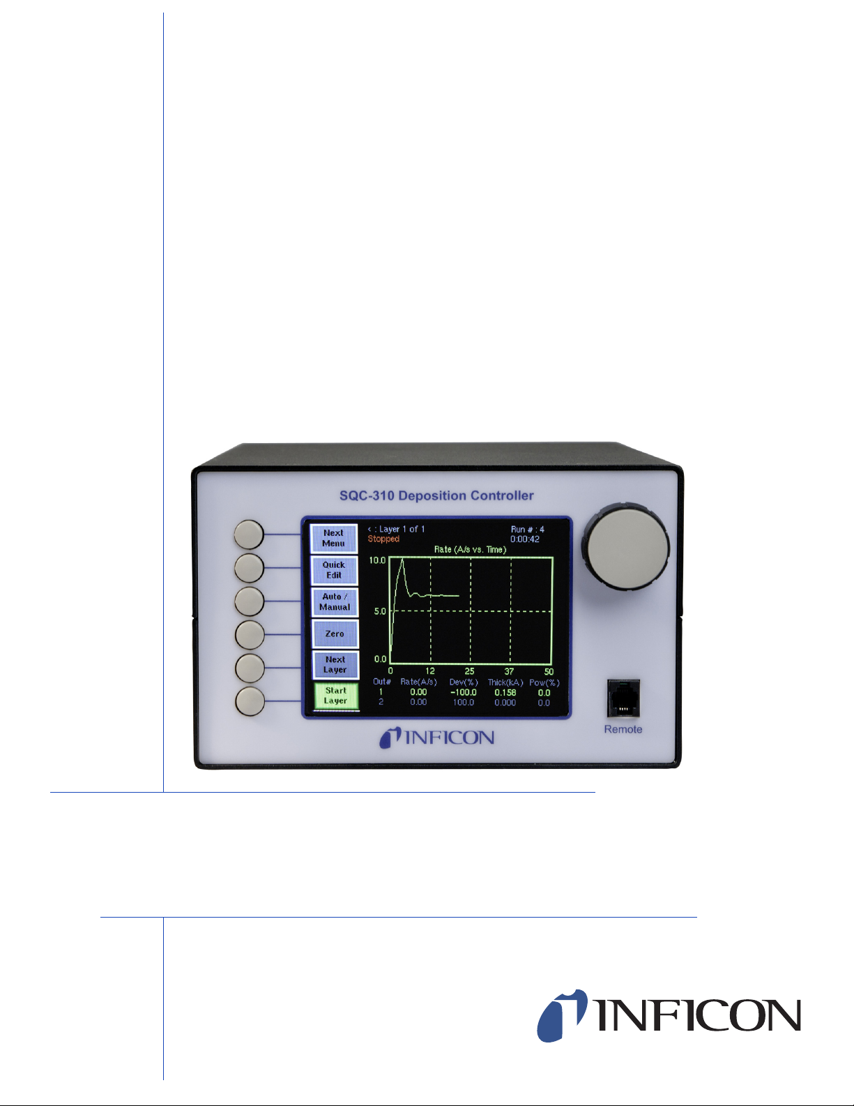
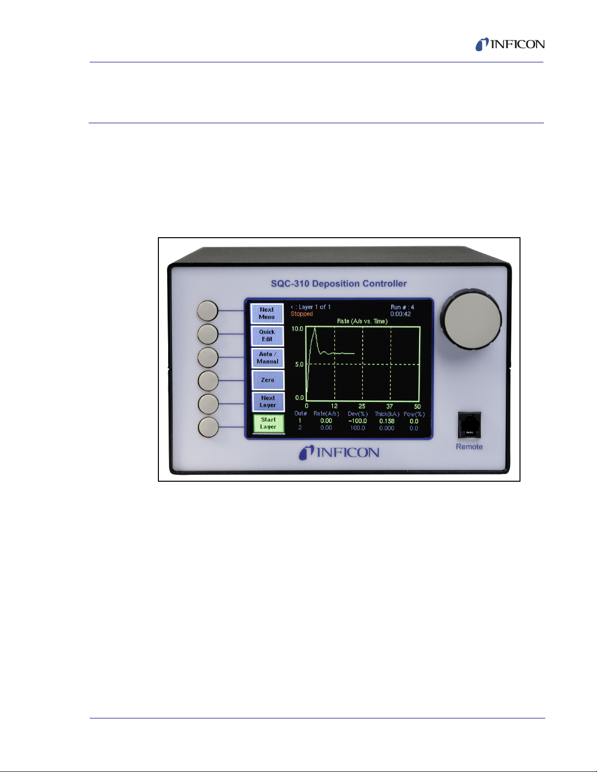
INFICON SQC-310 series instruments are multi-channel QCM-based deposition
controllers. They provide a unique combination of accuracy and powerful features
in a compact, low cost instrument.
Figure 1-1 SQC-310C
SQC-310 Operating Manual
Chapter 1
Quick Start
The standard SQC-310 measures up to two quartz crystal sensors, and controls up
to two evaporation sources. Eight process control relays and eight digital inputs are
IPN 074-550-P1B
included to support a broad range of external devices. The number of sensors,
outputs, and digital I/O can be doubled with an optional expansion card. The
SQC-310C co-deposition instrument allows simultaneous deposition of up to four
materials. RS-232 and USB communications are standard, with Ethernet optional.
NOTE: Both the SQC-310 and SQC-310C are referred to as the SQC-310 in this
manual. If there is a reason to distinguish between the two models, the
SQC-310 or SQC-310C model number will be called out.
This chapter will aid you in the initial setup and operation of your system. Please
review the entire manual for detailed operational, programming, and safety
information.
1 - 1
Page 14
SQC-310 Operating Manual
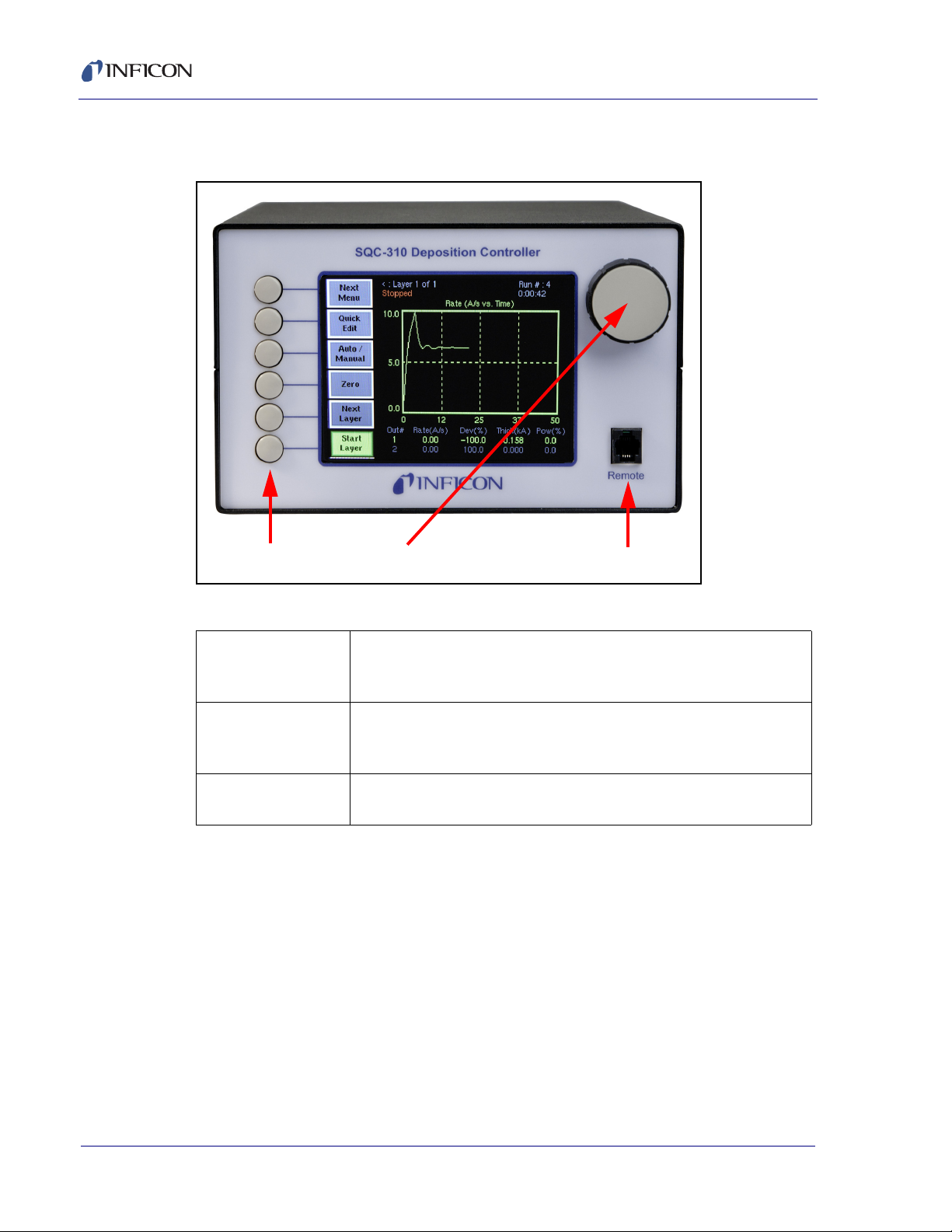
Soft Keys Control Knob Remote Jack
1.2 Front Panel
Figure 1-2 Front Panel Controls
Table 1-1 Front Panel Controls
SoftKeys Provide access to instrument operations and setup menus. The
functions of the SoftKeys change to adapt to different operations
and are displayed on the left of the screen.
Control
Knob
Remote
Jack
Used to adjust values and select menu items. Pushing the control
knob stores the current setting and moves to the next, similar to a
keyboard’s Enter key.
Connection jack for the optional handheld remote controller.
IPN 074-550-P1B
1 - 2
Page 15
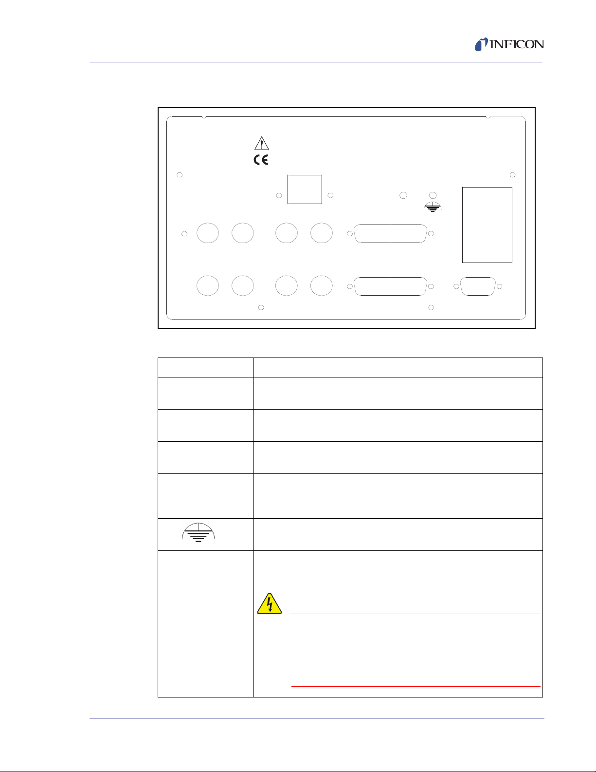
1.3 Rear Panel
WARNING - Risk Of Electric Shock
100-120/200-240 V~
50/60 Hz
25 VA
Sensor 1 Sensor 2 Output 1 Output 2
I/O 1-8
RS-232
Sensor 3 Sensor 4 Output 3 Output 4
I/O 9-16
Fuse T.5A 250V
SQC-310 Deposition Control ler
Serial No.
USB/Ethernet
Figure 1-3 Rear Panel
SQC-310 Operating Manual
Table 1-2 Rear Panel Connections
Sensor 1 & 2 Connects to the oscillator. See section 1.4 on page 1-4.
Output 1 & 2 Connects the SQC-310 output to your evaporation supply control
I/O (1-8) Connects 8 relays and 8 digital inputs to external equipment for
RS-232
USB or Ethernet
Sensor 3 & 4,
Output 3 & 4,
I/O 9-16
IPN 074-550-P1B
Power Input and
Fuse
input (see next section).
process control. See Appendix C.
Connects to a computer for programming and data acquisition.
RS-232 and USB are standard. Ethernet option replaces USB.
Increases the number of input, output, and digital I/O connections
when the optional expansion card is installed.
Measurement ground terminal useful for common system and
cable grounding.
Connects to mains power. The SQC-310 automatically detects
main voltages of 100-120 and 200-240 V (ac), 50/60 Hz
For continued protection, replace fuses
with the proper type and rating. Use
power cords only of the specified type
and rating, attached to a properly
grounded receptacle.
1 - 3
Page 16
SQC-310 Operating Manual
Sensor
In-Vac
Cable
Feedthrough
6 in. BNC Cable
Oscillator
Source
Shutter
BNC
Cables
Evaporation Supply
Output
Control Input
Ground Wire
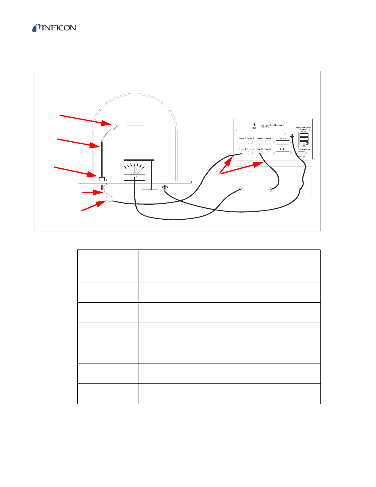
1.4 System Connections
Figure 1-4 System Connections
Table 1-3 System Components
Sensor Holds the quartz crystal used to measure rate and thickness.
Crystals must be replaced occasionally.
In-Vac Cable A coaxial cable that connects the sensor to the feedthrough.
Feedthrough Provides isolation between vacuum and atmosphere for electrical
and cooling lines.
6” BNC Cable Provides a flexible connection from the feedthrough to the
oscillator. Keep this cable as short as possible.
Oscillator Contains the electronics to operate the quartz crystal. Total cable
length to the crystal should be under 40 in.
Sensor Input
BNC Cable
Control Output
BNC Cable
Connects the oscillator to the SQC-310 sensor input. Lengths up
to 100 ft. are acceptable.
Connects the SQC-310 output to the evaporation source’s control
voltage input. Keep the length under 10 ft..
Ground Wire A wire, typically braided, that connects the vacuum system to the
SQC-310 ground terminal. Important for noise rejection.
IPN 074-550-P1B
1 - 4
Page 17

1.5 Installation
CAUTION
WARNING - Risk Of Electric Shock
Table 1-4 Installation
SQC-310 Operating Manual
Care should be exercised to route SQC-310 cables as far
as practical from other cables that carry high voltages or
generate noise. This includes other line voltage cables,
wires to heaters that are SCR-controlled, and cables to
source power supplies that may conduct high transient
currents during arc down conditions.
Rack
Installation
Power
Connection
Sensor Input
Connections
Source Output
Connections
IPN 074-550-P1B
Digital I/O
Connections
The SQC-310 occupies a 5.25 in. high, half-rack space.. An
optional installation kit (P/N 782-900-007) is available to adapt to a
full rack (see section 4.6 on page 4-3 ).
The SQC-310 automatically detects main voltages of 100-120 and
200-240 V (ac), 50/60Hz.
Verify that the power cable provided is
connected to a properly grounded mains
receptacle.
Connect the BNC cables and oscillators from your vacuum
chamber feedthrough to the desired SQC-310 sensor inputs. See
the previous section for cabling details.
Connect the BNC cables from the SQC-310 output connectors to
your evaporation supply control input. Consult your Power Supply
operator’s manual for control input wiring instructions.
Refer to Appendix C for details on wiring digital I/O to the SQC-310
Relay I/O connectors.
Computer
Connection
If you want to collect data or program the SQC-310, attach a
straight-thru RS-232 cable from the RS-232 connector to your
computer’s serial port.
You can also communicate via USB using a standard USB cable. If
you ordered the Ethernet option, the USB connection is replaced
with an RJ-45 Ethernet connector.
1 - 5
Page 18
1.6 Menus
Process 1 : Layer 1 of 1 Run # :0
0.0
50.0
100.0
0.0
6.2
12.5
18.8
25.0
Power ( % vs. Time)
Out#
1
2
3
4
Rate(A/S)
0.00
0.00
0.00
0.00
Dev( %)
00.0
00.0
00.0
00.0
Thick(kA)
0.000
0.000
0.000
0.000
Pow( %)
0.0
0.0
0.0
0.0
Stopped
0:00:00
SQC-310 Operating Manual
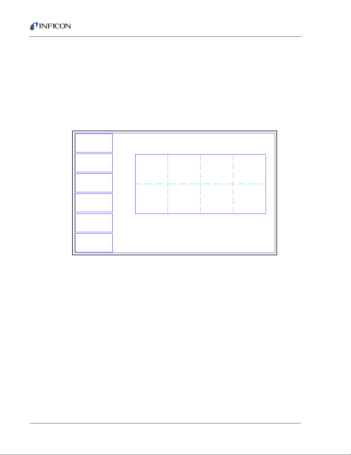
At power up the SQC-310 briefly displays the model number (SQC-310 or
SQC-310C) and firmware version information, then the Main screen. See Figure
1-5.
NOTE: If you are prompted for a password, use the switches along the left of the
screen to enter the password. The top switch is “1”, the bottom switch is
“6.” The Control Knob switch is "7." See section 5.3.3, Get/Set System
Parameters, on page 5-5 for password setup information.
Figure 1-5 Main Screen
Next
Menu
Quick
Edit
Auto /
Manual
Zero
Next
Layer
Start
Layer
The first line of the Main screen shows the name of the currently selected process.
After the process name are the layer that will run when the Start SoftKey is pushed,
and the total number of layers in the process. Further to the right is the number of
times this process has been run.
The second line of the Main screen is a status line. It displays the current phase
of the deposition cycle, and other status or error messages. When the process is
running, the right side of this line shows the process elapsed time.
Three graphs are possible: rate, rate deviation, and output power. The graphs
scale the vertical axis and scroll the horizontal axis based on the data displayed.
Below the graph are two lines that show deposition readings (four lines if the option
card is installed). This section shows current rate, rate deviation, thickness, and
output power as shown above. Alternatively it can show measured rate and
thickness versus rate and thickness setpoints.
IPN 074-550-P1B
1 - 6
The six SoftKey legends along the left side of the screen will change, depending
on the status of the process and the functions you select. Press Next Menu to
display alternate main screen menus. See Figure 1-6.
Page 19
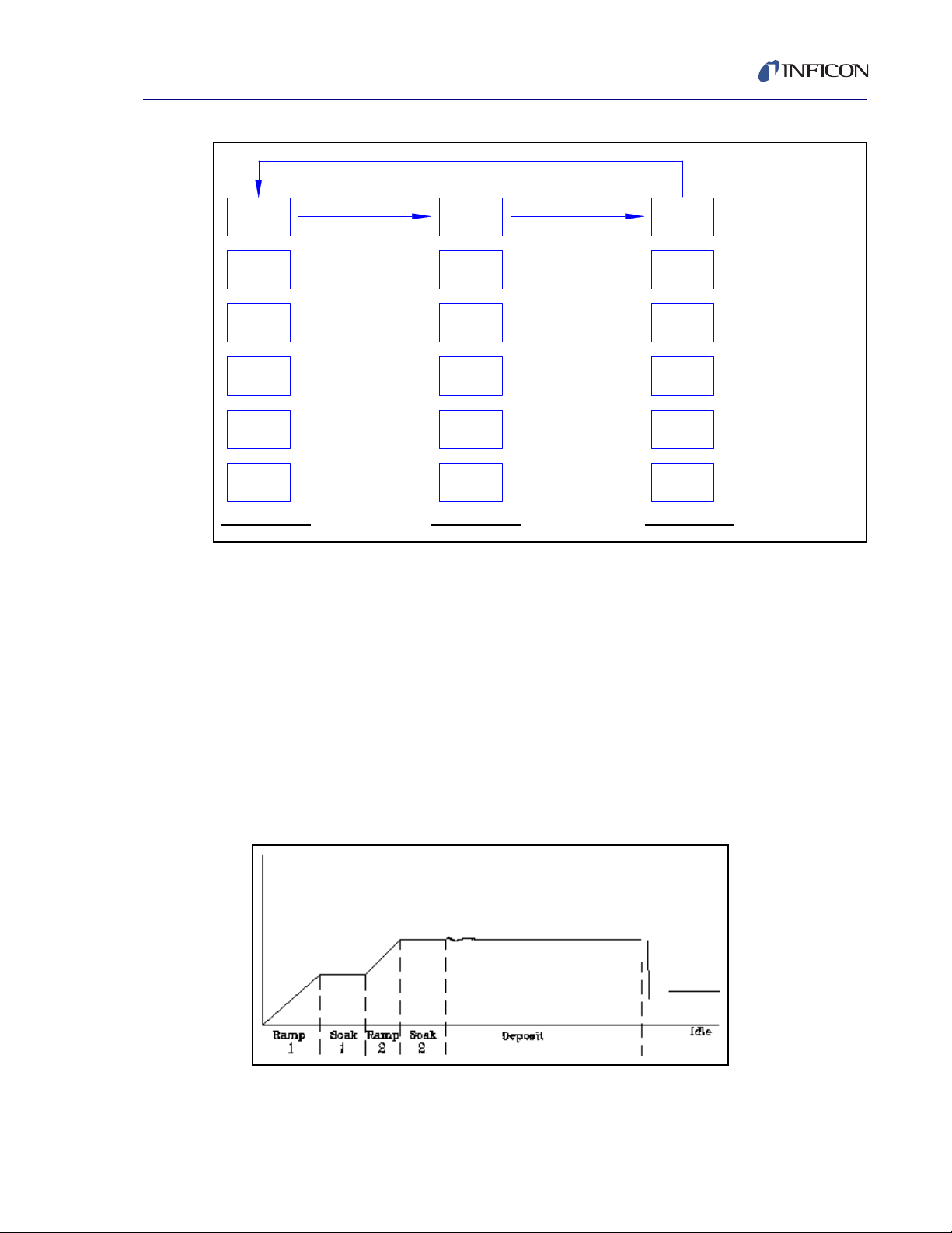
Figure 1-6 Alternate Main Screen Menus
Next
Layer
Start
Zero
Auto /
Manual
Next
Menu
Quick
Edit
Start
Next
Layer
Sensor
Info
Next
Display
Next
Graph
Next
Menu
Start
System
Menu
Film
Menu
Process
Menu
Next
Menu
Zero the thickness
reading on all
channels.
Switch between PID
and Manual power
control.
A
commonly edited
settings.
Select the next layer
in the process.
Start or Stop the
selected layer.
Switch graph between
rate, deviation, and
power.
Switch the readout
below the graph.
Display detailed
sensor information.
Select the next layer
in the process.
Start or Abort the
process.
Start the selected
layer.
Modify instrument
related settings.
Create or edit films to
be used as layers.
Create or edit process
layers.
Third menu available only
Layer
SQC-310 Operating Manual
Main Menu 1
ccess the most
Main Menu 1
Main Menu 2
Main Menu 2
Main Menu 3
when process is stopped.
Main Menu 3
Because Main Menu 3 provides access to functions that can completely redefine a
process, it is available only when the process is stopped.
IPN 074-550-P1B
1.7 Thin Film Deposition Overview
Spend some time now moving between the three menus. Pay particular attention
to the effects that the Main Menu 2 selections have on the display. We will cover
the setup parameters of Main Menu 3 in the Building a Process section.
The SQC-310 stores the recipes, and provides the operating functions, required to
control thin film deposition processes. A typical thin film deposition cycle is shown
in Figure 1-7.
Figure 1-7 Typical Thin Film Deposition Cycle
1 - 7
Page 20

SQC-310 Operating Manual
CAUTION
The cycle can be broken into three distinct phases:
Pre-conditioning (ramp/soak)
Deposition
Post-conditioning (feed/idle)
During pre-conditioning, power is supplied in steps to prepare the evaporation
source for deposition. Once the material is near the desired deposition rate,
material deposition begins.
During deposition, the PID loop adjusts the evaporation source power as required
to maintain the desired rate. In Co-deposition, multiple films can be deposited
simultaneously.
When the desired thickness is reached, the evaporation source is set to idle power.
At this point the process may be complete, or deposition of another layer may
begin.
1.8 Building a Process
This section presents a brief guide to building and running a simple one layer
process. Chapter 2 covers instrument operation in much greater detail.
Table 1-5 Create a Film
Create a
Film
A film is a material to be deposited, and its associated deposition
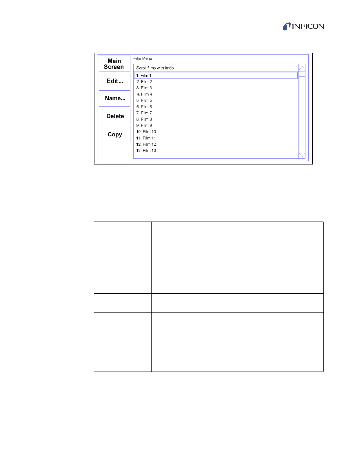
settings. Initially the list of films may be empty.
Press Next Menu until the Film Menu SoftKey is displayed. Press
Film Menu to view a list of stored films. Turn the control knob to
scroll to an entry in the list that is currently labeled <Empty>.
Press the Create SoftKey to create a default film at that location.
Note the film number that you just created. For now, accept the
default film parameters.
Press Main Screen to return to the main screen.
Be sure to exit to the Main Menu before powering the
instrument down if you have made changes to settings.
Your changes may not be saved otherwise.
IPN 074-550-P1B
1 - 8
Page 21
SQC-310 Operating Manual
Figure 1-8 Film Select Menu
NOTE: Films are numbered from 1 to 50. Film names and process names can be
changed by pressing the Edit Name SoftKey.
Now that we are sure that at least one film exists, we will build a simple single layer
process using that film.
Table 1-6 Building a Layer
Select
Press the Process Menu SoftKey to view a list of processes.
Process
Turn the control knob to scroll to an entry in the list that is labeled
<Empty>.
Press the Create SoftKey to create a default process at that
location.
Press the Select SoftKey to make the selection the active process.
Edit Press the Edit SoftKey to view a list of layers in the selected
process. The layer list should be blank.
IPN 074-550-P1B
Edit
Layer
Press Insert New..., then scroll down the list of films to the film you
just created.
Press Insert Normal to insert the selected film as Layer 1. The
display returns to the Layer Select menu.
NOTE: On SQC-310C, Insert Codep is also available to create
Co-deposited layers.
1 - 9
Page 22
SQC-310 Operating Manual
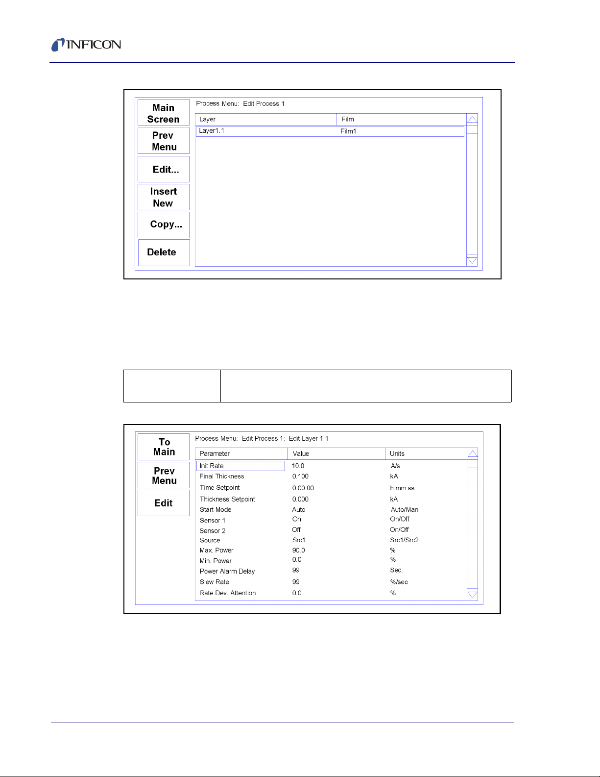
Figure 1-9 Layer Select Menu
A process consists of one or more layers. Each layer can have a different film, or
even multiple films (Co-deposition). For this example, we will stop with only a
single layer. Layers are displayed as "Layer x.y", where x is the layer number and
y is the source number assigned to the layer.
Table 1-7 Edit Layer
Edit
Layer
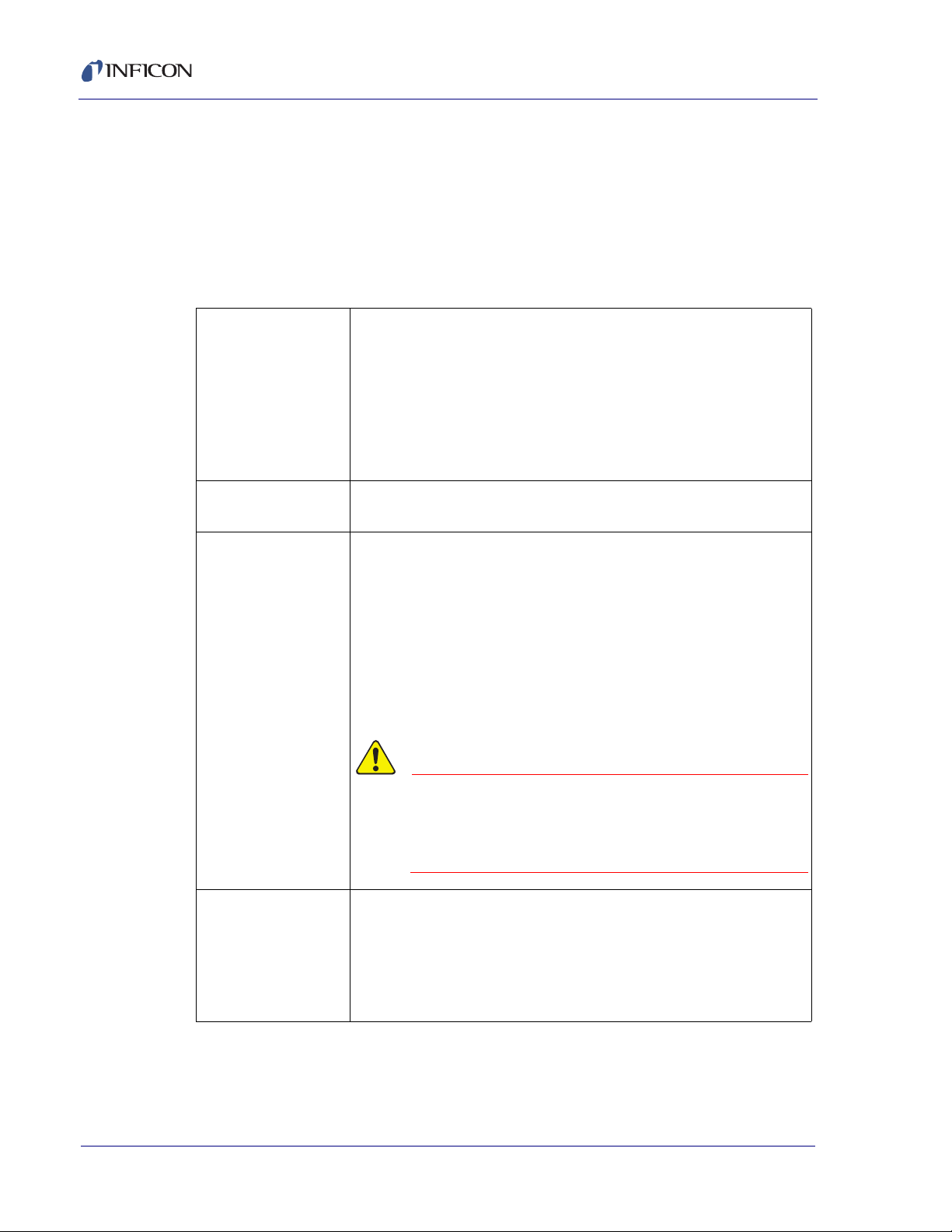
Figure 1-10 Edit Layer Menu
With Layer 1.1 selected, press Edit to display the Layer Edit menu
for Layer 1.1.
IPN 074-550-P1B
1 - 10
Page 23

Table 1-8 Editing a Setting
SQC-310 Operating Manual
Edit Menu
Operation
To edit a setting in any menu, turn the control knob to scroll to the
desired setting, then press the Edit SoftKey. The cursor moves to
the setting value, and the SoftKey functions change to show:
Next: Store the parameter and move to next parameter for editing.
Cancel: Stop editing and return the selected parameter to its
previous value.
Enter: Stop editing and save values for selected parameter.
In Edit mode, adjust the control knob to set the desired parameter
value.
Edit
Layer 1
Spend some time navigating through the Layer 1 parameters and
editing values. Be sure to enter an Initial Rate and Final Thickness,
and select a Source and Sensor(s).
Press To Mai n to return to the Main Screen.
We have completed the design of a single layer process.
IPN 074-550-P1B
1 - 11
Page 24
SQC-310 Operating Manual
CAUTION
1.9 Depositing a Film
NOTE: You can simulate the steps below, without actually depositing a film, by
going to the System Menu and selecting Simulate Mode ON. Simulate
mode is useful for testing processes before applying power to the
evaporation supply. See section 3.11 on page 3-19 for detailed System
Menu information.
Table 1-9 Depositing a Film
Verify Sensor
Operation
Show
Power Graph
Verify Output
Operation
Press Next Menu until the Sensor Info option is shown.
Press Sensor Info to display the quartz sensor readings. Sensor 1
should be ON and display a % life of over 50%. If not, check your
sensor connections (see section 1.3 - section 1.5), and refer to
Min/Max Frequency (System Menu, see section 3.11).
Press Exit to return to the main screen.
Press the Next Graph SoftKey until the graph shows Power (% vs.
Time).
Press the Next Menu SoftKey until the Auto/Manual SoftKey is
displayed. Now press Auto/Manual until Manual/Auto is displayed.
Press Start Layer to begin deposition in manual mode.
Slowly turn the control knob to increase the control voltage to your
evaporation supply. Verify that the Power(%) reading for Output 1
(lower right, below graph) approximates the actual output of your
evaporation supply. If not, check your hookup (see section 1.3 -
section 1.5), and refer to Scale Voltage (section 3.11.3.2).
1 - 12
Observe the output power versus your
evaporation supply’s actual output. If
there is a problem, press the Stop
SoftKey immediately.
Enter
Auto Mode
Press the Next Menu key until the Manual/Auto SoftKey is shown.
Press Manual/Auto to change the SoftKey display to Auto/Manual.
This places the output under PID deposition control.
Press Stop at any time to halt deposition and set output power to
zero.
Please take time to review the remainder of this manual for detailed operational,
programming, and safety information.
IPN 074-550-P1B
Page 25

2.1 Introduction
This chapter describes common tasks associated with operating the SQC-310. It
assumes that you understand basic operation of the menus and parameter setup
as described in Chapter 1, Quick Start. Detailed definitions of each parameter can
be found under the appropriate menu description in Chapter 3, Menus.
2.2 Definitions
Several terms will be used repeatedly throughout this manual. It is important that
you understand each of these terms.
Material: A physical material to be deposited. A database of 100 materials is stored
in the SQC-310. Three parameters completely define a material: Name, Density,
and Z-Ratio (also called Z-Factor). A table of common materials, their densities,
and Z-Ratios is listed in Appendix A.
Film: A film describes in detail how a material will be deposited. It includes the
material definition and all of the preconditioning, deposition, and post conditioning
variables necessary to accurately deposit the material. Because the film definition
does not include rate and thickness information, a single film can be used in several
different layers and processes. The SQC-310 stores up to 50 films.
SQC-310 Operating Manual
Chapter 2
Operation
Layer: Layers are the basic building blocks of processes. A layer consists of a film
and the thickness and rate setpoints for that stage of the process. Layers also
define which outputs and sensors will be used at that point in the process.
Co-deposition of multiple films occurs when more than one output is active during
a layer.
Process: A process is a sequence of layers to be deposited. The SQC-310 can
store up to 100 processes, consisting of a total of 1000 layers.
Phase: A step in the deposition cycle. Preconditioning phases include Ramp 1,
IPN 074-550-P1B
Soak 1, Ramp 2, and Soak 2. Deposit phases include indexer rotate, shutter delay,
deposition, and deposition rate ramps. Post-conditioning phases include Feed
Ramp, Feed, and Idle Power.
Figure 2-1 Phase
2 - 1
Page 26
SQC-310 Operating Manual
2.3 Defining a Film
A film is a material to be deposited, plus all of its associated setup parameters.
Keep in mind that a film can be used in multiple layers, or even multiple processes.
Editing a film’s parameters will cause changes to every location where the film is
used.
To define a film, press Next Menu until Film Menu is shown (Menu 3). Press Film
Menu. A list of 50 films (or <Empty>) will be displayed. To define a new film, scroll
to <Empty> and press Create. To change the name of a film, scroll to the film and
press Edit Name. Scroll through the character set and Insert each character for
the film name. Press Save to return to the Film Menu. Press Edit to display the
parameters for this film.
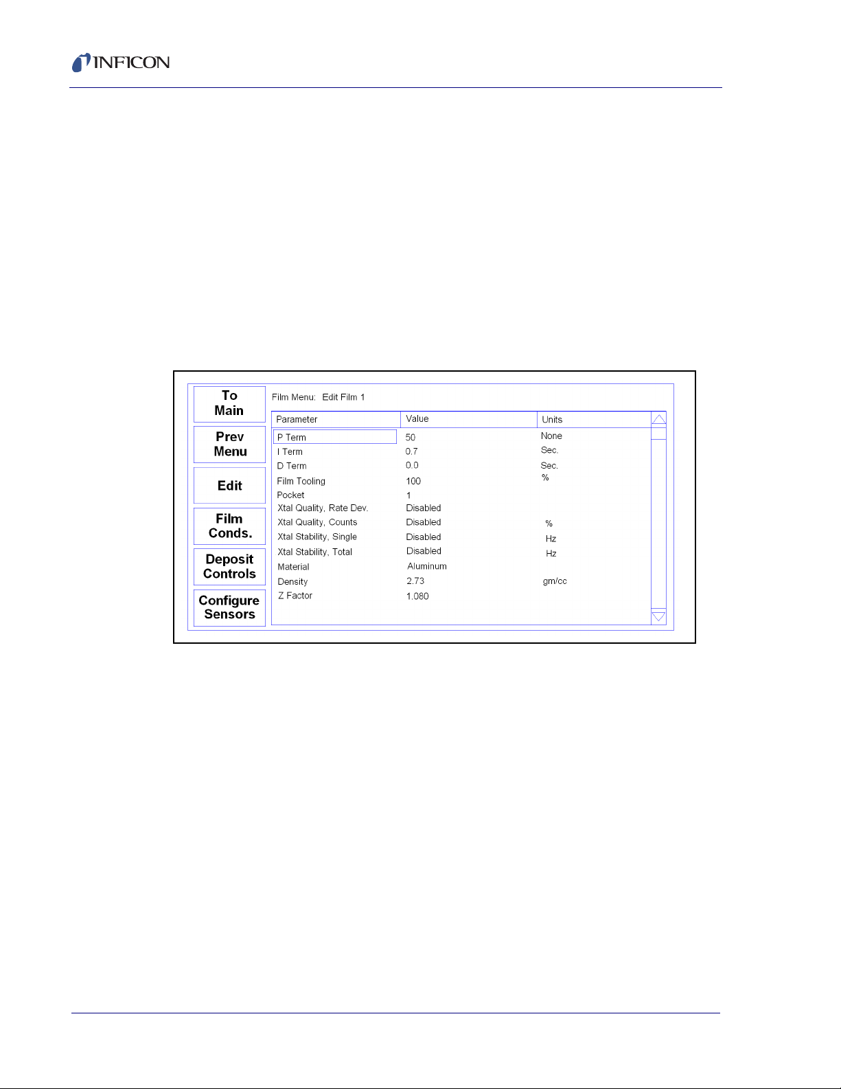
Figure 2-2 Film Edit Menu
2 - 2
P Term is the proportional gain, which is the % process rate change divided by the
% input power change. The I Term (integral) sums the rate deviations over time to
more accurately achieve the rate setpoint. The D Term (derivative) speeds
response to sudden changes in rate. Volumes have been written on determining
the proper PID settings. See section 2.8 on Loop Tuning later in this chapter for a
common PID loop tuning procedure. Start with P=25, I=.5, D=0.
Film Tooling adjusts for differences in actual versus measured thickness for this film
(material). This parameter is seldom used, but can adjust for material specific
dispersion patterns. See Xtal Tooling in the System menu for the more commonly
used tooling correction.
Pocket selects the source pocket used for this film. This parameter requires that
the System Menu, Source Setup be configured for an indexer (Sensors and
Sources Menu, see section 3.11.3).
The next chapter will cover Crystal Quality and Stability. For initial operation leave
Quality and Stability disabled.
IPN 074-550-P1B
Page 27
SQC-310 Operating Manual
With Material highlighted, press Edit to scroll through the list of available materials.
Select the desired material and press Enter. You could also change the Density
and Z-Ratio for the selected material, but it is unlikely those values are wrong. You
cannot add materials, but you can edit the Name, Density, and Z-Ratio of one of
the 100 existing materials.
Film conditioning adjusts the output power level to achieve a desired material state
before and after deposition. Press Film Conds to enter the film conditioning menu.
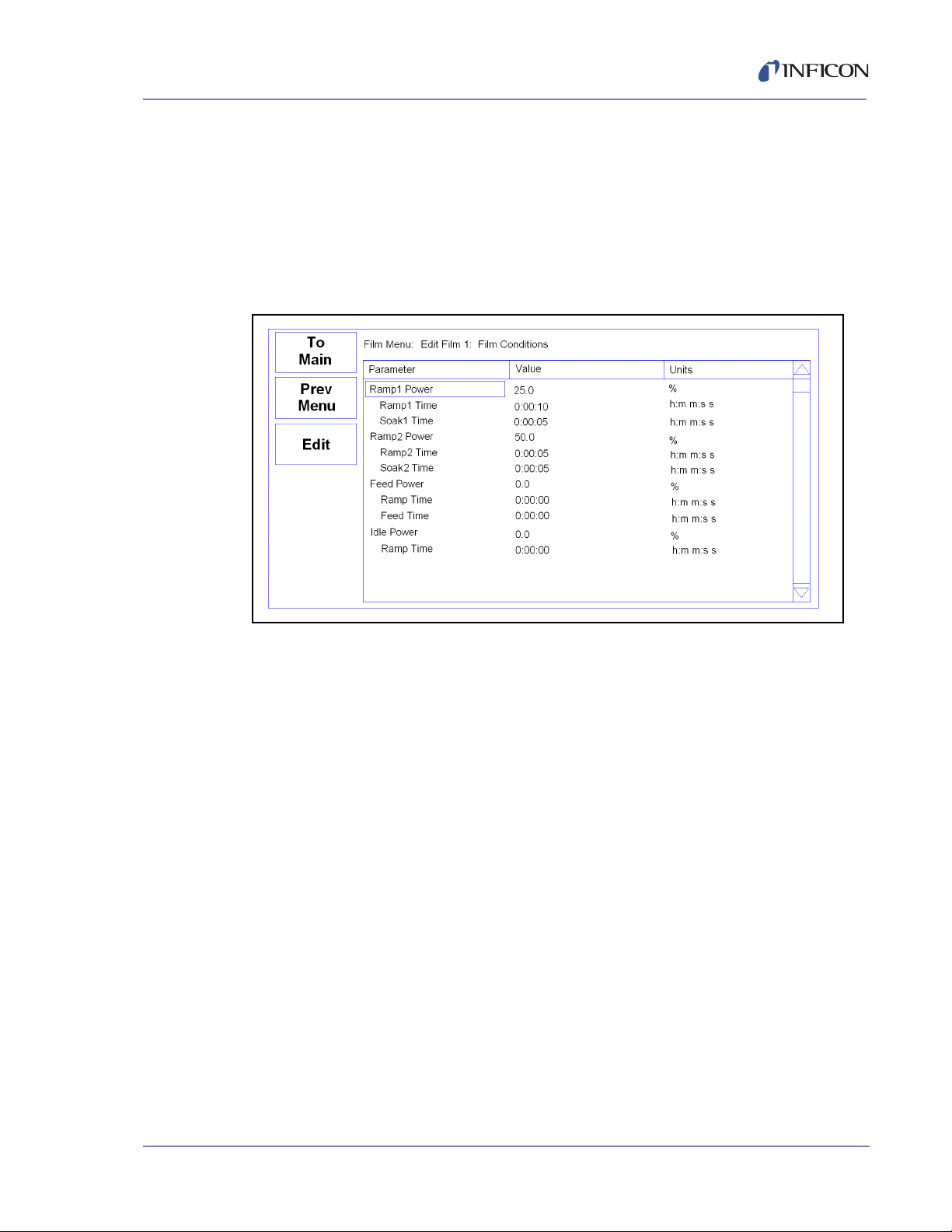
Figure 2-3 Film Conditioning Menu
Ramp1 starts at 0% power and increases the power during Ramp1 Time to the
Ramp 1 power level. Set the Ramp 1 Power and Time to gradually bring the
material to a near molten state. Set the Soak 1 Time to a value that will allow the
material to homogeneously achieve that state. Ramp 2 is used to slowly bring the
material to a power level that nearly matches the desired deposition power. Use
Soak 2 to hold the material at that level until deposition (i.e., rate control) begins.
If you use wire feed to replenish material after deposition, set the Feed Power and
times as required. The idle conditioning phase typically ramps output power back
IPN 074-550-P1B
toward zero at the end of a process.
From the Film Conds menu, press Prev Menu to return to the main Film Menu.
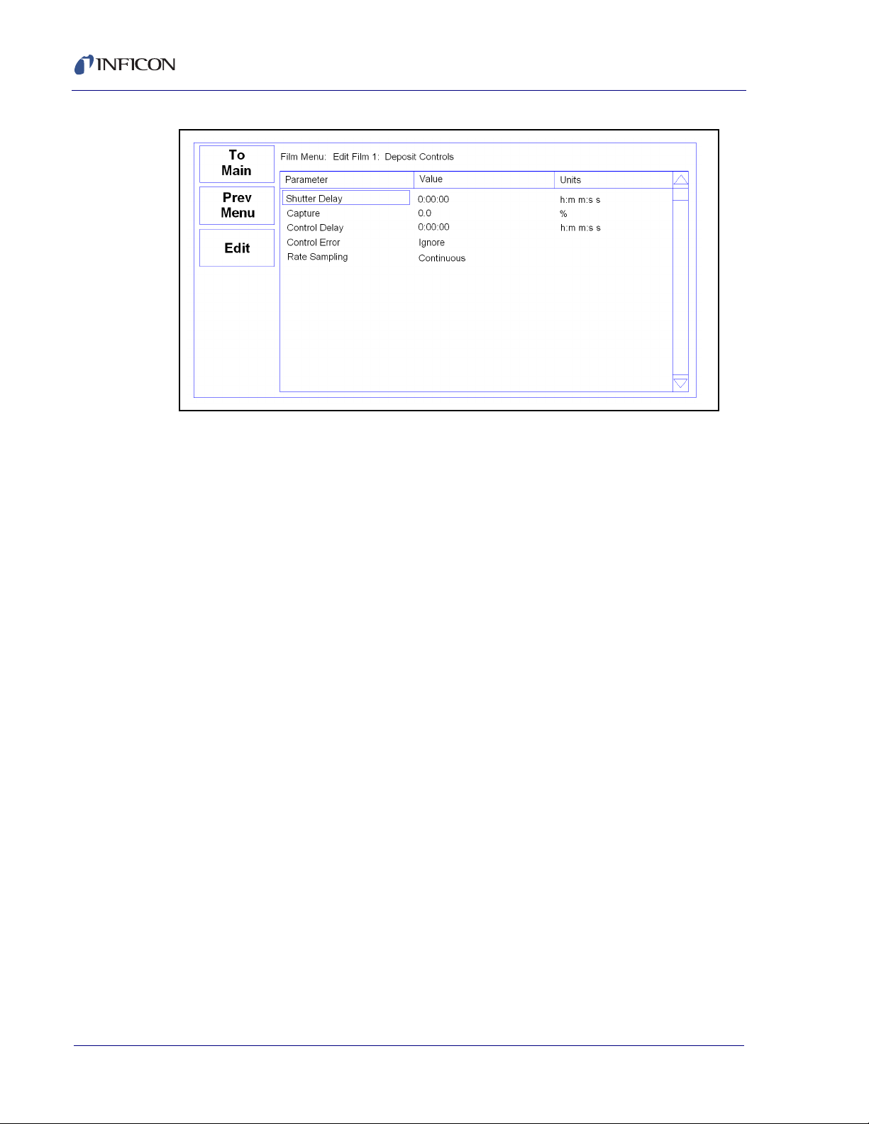
Now press Deposit Controls. The Deposit Controls menu contains parameters
that modify operation during the deposition phase. See Figure 2-4.
2 - 3
Page 28
SQC-310 Operating Manual
Figure 2-4 Deposition Controls Menu
Shutter delay causes the SQC-310 to delay opening the shutter until the process
has stabilized at the desired deposition rate. Capture is the % rate deviation that
must be achieved to open the shutter and go to the Deposit phase. Shutter delay
is the maximum amount of time to wait for capture to be achieved. Set Shutter
Delay and Capture to zero to disable this feature.
NOTE: During co-deposition, the SQC-310 waits for all films to achieve capture
before moving to the deposit phase. If any film fails to achieve rate capture
within its programmed shutter delay time, an error occurs.
When the Control Delay function is used, the control loop will not react to the rate
for a set amount of time at the beginning of the Deposit state. This helps to
eliminate overcompensation by the control loop due to rate spikes when the sensor
or source shutter opens. Control Delay is the amount of time the SQC-310 will wait
before the control loop takes over.
Control Error is a setting that instructs the SQC-310 what to do if it is unable to
maintain the desired deposition rate (for example, out of material or a bad sensor).
One of three actions is possible: Keep trying (Ignore), set power to zero to halt
deposition (Stop), or maintain constant power (Hold) and extrapolate thickness
from the last good rate reading. Until your process is known and stable, it is best to
leave the Control Error setting on Ignore.
Rate sampling can extend sensor life in high rate processes. Select Cont
(continuous) to disable rate sampling. A Time selection closes the shutter for a
fixed time, then opens the shutter for a fixed time to sample the rate. Acc Based
(accuracy based) sampling closes the shutter for a fixed time, then opens the
shutter until the desired rate is achieved. Rate Sampling assumes a very stable
process!
IPN 074-550-P1B
2 - 4
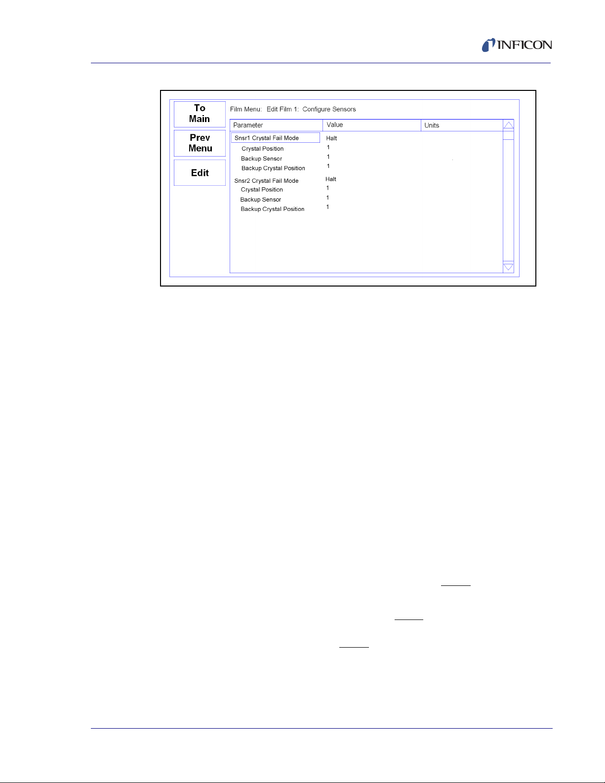
Now, from the main Film Menu, press Configure Sensors. This menu defines
operation of the film when a sensor fails. See Figure 2-5.
Page 29
SQC-310 Operating Manual
Figure 2-5 Configure Sensor Menu
Crystal Fail mode selects the action taken when a sensor crystal fails. Select Halt
to halt the process on failure. Select Halt Last if multiple sensors are used for this
film. Select Timed Power to enter Timed Power mode using the last good
rate/power measurements. Select Switch to Backup to switch to a backup crystal.
The next three parameters define which position of a multi-crystal sensor is used
as the primary, and which is the backup. The number of sensor positions displayed
is determined by the sensor configuration on the Sensors & Sources screen of the
System Menu.
2.4 Defining a Process
To define a process, press Next Menu until the Process Menu SoftKey is shown.
Press Process Menu. A list of 100 processes (or <Empty>) will be displayed. To
define a new process, scroll to <Empty> and press Create. A new Process# is
added to the list of existing processes. Press Edit Name to change the process
name.
IPN 074-550-P1B
Press Select, then Edit to display the sequence of layers and films that comprise
the selected process. To add the first layer, press Insert New. Select a film from
the films screen and press Insert Normal. To add more layers, scroll to below the
last layer and press Insert New. Layers are always added above
the selected
layer.
To insert a layer in a sequence of layers, scroll to below
the desired location in the
layer sequence, and press Insert Normal. Select a film from the list and press
Insert Normal to insert the new layer above
the selected layer. The selected layer
and subsequent layers will be shifted down.
HINT: When building a process it may be easiest to add a “dummy” last layer and
keep inserting above that layer. When the process is complete, delete the
“dummy” layer.
2 - 5
Page 30
SQC-310 Operating Manual
To add a Codeposited film to an existing layer, scroll to below the desired
Co-deposition layer. Press Insert New, select the desired film, then press Insert
CoDep. The Codeposited film will be inserted in the layer above
the selected layer,
and indented to show that it is a Co-deposition film. CoDep is available only on the
SQC-310C.
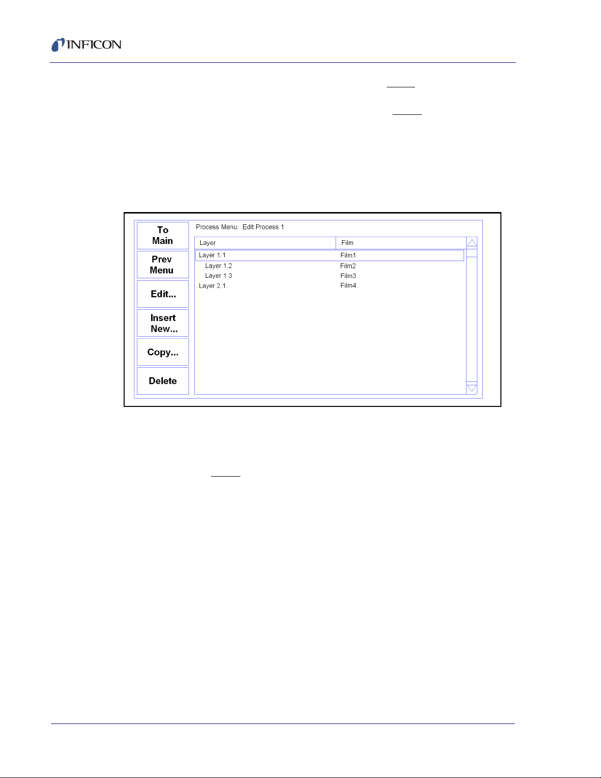
Figure 2-6 shows two films being Codeposited with Film1, then a fourth film being
deposited as an additional layer. While layers are always numbered sequentially,
the films are sequential only for this example. Any film can be used in any layer.
Figure 2-6 Edit Layer Menu
To delete a layer, highlight it in the Layer Select menu and press Delete.
To move or duplicate a layer, highlight it in the Layer Select menu and press Copy.
On the Paste menu, press Paste to replace a layer. Press Insert Normal or Insert
CoDep to insert it above the highlighted layer. A copy of the layer is saved to the
cut/paste clipboard memory.
NOTE: Once a film is assigned to a process layer, you cannot change the film.
Instead, cut the layer, then insert a new layer and select the desired film.
IPN 074-550-P1B
2 - 6
Page 31

2.5 Defining a Layer
To edit a Process Layer, press Process Menu. Select the desired process,
then press Edit. Finally, select the desired layer and press Edit....
Figure 2-7
SQC-310 Operating Manual
Initial Rate and Final Thickness are the main process setpoints for the film used in
this layer. Time Setpoint and Thickness Limit are secondary values that can
activate a relay when they are reached.
Start Mode controls operation in multi layer processes. In Auto Start the layer starts
immediately on completion of the previous layer. Manual Start waits for a user
signal via the front panel, digital input, or communications port to start the layer.
Don’t confuse this Manual Start mode with the Manual Power SoftKey function.
The SQC-310 can use multiple sensors to measure a film’s deposition rate and
thickness. If multiple sensors are selected, an average of the sensors is used. Set
each sensor that will be used to measure this film to ON.
The Source entry assigns the layer to a specific SQC-310 rear panel source output.
The layer (and associated film parameters) will be applied to the selected output.
IPN 074-550-P1B
Assign the Max, Power, Min. Power, Power Alarm Delay and Slew Rate
appropriate for the material and your power supply. For now, set Max Power & Slew
rate to 100%. Set them to lower values if you find that small power changes cause
excessively large changes in deposition rate. Leave Rate Deviation alarms at 0%
for now.
Rate Ramps allow the PID controlled deposition rate to change over time, under
PID control. Each rate ramp has a starting thickness, an elapsed time to ramp to
the new rate, and a new rate setpoint. Each process layer can have up to two rate
ramps.
2 - 7
Page 32

SQC-310 Operating Manual
Crystal Tooling
Number of Positions
2. Sensor 2
1. Source 1
2. Source 2 Indexer
Single Crystal
1
100%
v
Sensors & Sources Menu
Name
1. Sensor 1
Shutter
No
Substrate
Substrate
Tooling
Over 100%
Tooling
Under 100%
2.6 Sensor and Source Setup
The SQC-310 must be configured to match the type of sensor installed in your
system. We will set up a single sensor without a shutter. Chapter 3 discusses the
other Sensor configuration options.
Select System Menu, Sensors & Sources, scroll to Sensor 1 and press Select to
Display the Sensor 1 menu. See Figure 2-8.
Figure 2-8 Sensor 1 Edit
To
Main
Value
Pre
Menu
Done
Single Source
Edit
Crystal Tooling adjusts for the difference in measured deposition rate between the
sensor and the substrate being coated.
Figure 2-9 Tooling Over/Under
IPN 074-550-P1B
In the left illustration in Figure 2-9, the sensor will measure less rate or thickness
than is actually deposited on the substrate because of its positioning. In the right
illustration, the sensor will measure high. Tooling is the ratio of the actual substrate
deposition rate or thickness, to that measured by the sensor.
A simple rule to remember is: If the rate/thickness reading is low, then increase the
tooling value. If the rate/thickness reading is high, then lower the tooling value.
2 - 8
Page 33

SQC-310 Operating Manual
If your sensor has a shutter, select Dual or Yes. Dual sets the sensor inputs for a
dual sensor (one that uses two sensor inputs). Yes is used for either a shuttered
single or multi-crystal sensor. Either Dual or Yes will automatically assign the first
available relay as the shutter relay. The relay opens immediately when a layer
enters the Deposit, Shutter Delay, or Control Delay states.
For multi-crystal sensors set Number of Positions to the number of crystals.
Several other parameters are required for multi-crystal heads. Set the Control type
and Feedback for the type of Digital I/O used by your sensor. The SQC-310 will
automatically create relays and inputs to control the sensor. Detailed explanations
of multi-crystal setup can be found in section 3.11.3.1, Sensor Setup, on page
3-31.
Source setup is nearly identical to the Sensor Setup described above.
Set the Voltage Scale to the control voltage that corresponds to 100% output on
your source supply. The SQC-310 uses 0 volts as 0% output, and the programmed
value as 100% output. Scale values from –10 volts to 10 volts are possible.
Source shutters will open after pre-conditioning, when deposition begins. In your
system, this may actually be the substrate shutter.
For a multi-position source, select the number of positions. Control and feedback
settings similar to those used for multi-position sensors become available. See
section 3.11.3, Sensors and Sources Menu, on page 3-31 for detailed information
on these settings.
2.7 Running a Process
Once a Process is defined with the desired Layers, and the sensors and source
supply are properly connected, the deposition process is ready to run. This section
describes the steps to select, start, and stop a process.
NOTE: Depending on the Main Menu screen displayed, the last key will be shown
as either Start or Start Layer. For simplicity, this section will use Start to
refer to either.
IPN 074-550-P1B
There are three Main Menu screens while the process is stopped (two when it is
running). Pressing the Next Menu SoftKey accesses the three screens. Next Menu
is the first SoftKey in each of the three menus. Likewise, Start/Stop is the last
SoftKey on each Main Menu. Main Menu 1 displays the SoftKeys used to control
the process.
2 - 9
Page 34

SQC-310 Operating Manual
Figure 2-10 Main Screen
The Quick Edit SoftKey (available while the process is running) provides easy
access to the most commonly set process parameters.
Figure 2-11 Quick Edit Menu
2 - 10
IPN 074-550-P1B
Press Next Layer and Prev Layer on the Quick Edit screen to review each layer.
Press To Main to return to the Main screen.
Page 35

SQC-310 Operating Manual
Figure 2-12 Main Screen
The Auto/Manual key alternates between Automatic (PID) output control and
Manual (user) output control. In Manual mode, the SQC-310 immediately starts the
deposition phase for the current layer, whether the process was stopped or
running. However, the PID loop is disabled and the front panel control knob
controls output power.
In Manual Mode, you will usually display the Rate Graph, and manually adjust the
output power to achieve the desired deposition rate. It is easy to exceed a layer’s
Final Thickness in Manual mode, so watch the Thickness reading carefully. Manual
mode is particularly useful for determining preconditioning power levels, and loop
tuning.
Moving from Manual mode to Auto mode places the SQC-310 into automatic (PID)
control. The PID control loop will try to achieve rate setpoint, so there may be a
rapid change in output power.
NOTE: Don’t confuse the Auto/Manual SoftKey with a layer’s Manual/Auto Start
parameter. Manual/Auto Start is an Edit Layer parameter that tells the
SQC-310 to wait for operator intervention before starting a Layer.
IPN 074-550-P1B
The Zero SoftKey can be used to zero the thickness reading at any time. It is not
normally needed, since the SQC-310 automatically zeroes the thickness at the
beginning of each layer. However, it is useful when simulating a process, and when
operating in Manual mode.
Next Layer moves the starting point for the Start SoftKey to the next layer,
wrapping back layer 1 at the end of the process.
The last SoftKey on this menu is used to Start and Stop the deposition cycle. Press
Start to start the layer shown on the first line of the screen at the preconditioning
phase. Press Stop Layer to halt the current layer. You can restart the current layer
by pressing Start. Press Next Layer, then Start, to start any other process layer.
2 - 11
Page 36

SQC-310 Operating Manual
NOTE: It is best (and safest!) to place the SQC-310 in Simulate mode when a
process is first run. If the bottom SoftKey does not show Start Simulate,
press System Menu and turn Simulate Mode ON.
Enough preliminaries, let’s start the process!
Press Start to start deposition. If the first layer Start mode was programmed as
Manual, you will need to press the Start Layer SoftKey now to start the layer.
Figure 2-13 Preconditioning
The process starts with the first layer preconditioning phase. When preconditioning
is complete, the deposition phase begins. The deposition phase ends when Final
Thickness is reached for the layer, then Feed and Idle phases run (if programmed).
If the second layer is Auto Start, its cycle begins immediately when the first layer is
complete. If the second Layer is Manual Start, or it’s the last layer in the process,
the process halts and waits for operator intervention.
While the process is running, a Stop Layer SoftKey is shown. Pressing Stop Layer
temporarily halts the current Layer.
IPN 074-550-P1B
2 - 12
Page 37

SQC-310 Operating Manual
Figure 2-14 Layer Stopped
Start repeats the stopped layer, beginning with preconditioning. Next Layer allows
you to select another layer to start.
NOTE: Pressing the Reset SoftKey on Main Menu 2 at any time completely aborts
the process.
Spend some time in Simulate mode verifying that the process sequences through
each phase of each layer as expected. If not, use the Quick Edit, Process, and Film
menus to make corrections.
Because the process is being “simulated,” some parameters will not be correct for
your process (particularly PID). However, you can become familiar with the effect
of each parameter in this simulated process. Also practice using the Next Menu
options, especially Auto/Manual modes.
Once you have verified the process in Simulate Mode, you may return to the
System menu and turn Simulate OFF to start testing your process. Use the next
section to finalize the loop PID settings.
IPN 074-550-P1B
2.8 Loop Tuning
This section will help you adjust your SQC-310 to achieve a stable deposition
process. Keep in mind that there is no “best” way to determine tuning parameters,
and no one set of settings that are best.
The first factor to consider is the type of deposition source. Thermal sources are
slow responding and typically free of noise transients. To avoid overshooting and
constantly seeking setpoint, they require PID parameters that anticipate their long
dead time and slow response to changes. Ebeam sources, on the other hand, are
fast responding and often noisy. They are also subject to arcing, which can create
large electrical noise spikes.
2 - 13
Page 38

SQC-310 Operating Manual
NOTE: Control loop tuning is a trial and error process and there is no "best"
procedure to accomplish this task. The procedure described here works
best for fast sources.
Set System Parameters: A Period of 0.25 seconds is a good starting point. Set
Tooling parameters to 100% for now. Initially set the Rate Filter to 1.00 (no filter) to
see the noise of the system. Simulate should be OFF. Keep in mind that Simulate
mode is a tool for testing process layers. It is not likely to match the control
response of your vacuum system.
Create a One-Layer Test Process: Create a new film with all default values and
select the material you will be depositing. Create a process that has the new film
as its only layer, and edit that layer. Set Init Rate to your desired rate and Final
Thickness to a large value to avoid the layer stopping during the tests. Select the
proper Sensor(s) and Source. Leave the other layer and film parameters at their
default values.
Test the Setup: Press Next Menu until the Sensor Info button is displayed, and
press Sensor Info. Verify that the Sensor Status is ON and a stable frequency is
displayed. Exit to the main screen and press Next Menu until the Auto/Manual
button is displayed. Press Auto/Manual to enter Manual mode, then press Start
Layer.
Slowly turn the control knob to a power of 10%, and verify that your power supply
output is about 10% of full scale. Continue to turn the control knob until a Rate near
your desired setpoint is achieved. Again, verify that the power supply output agrees
with the SQC-310 Power (%) reading. If the readings don’t agree, check your wiring
and verify that the System Menu, Source setup Voltage Scale agrees with your
power supply’s input specifications.
With the power set to your desired rate (Init Rate in the Quick Edit menu), push
Next Menu then Next Graph until the Rate Deviation graph is displayed, and
observe the noise. If the system has significant short term noise at fixed power
(maybe >10%), the control loop will be very difficult to adjust, especially at low
rates. It is better to eliminate the source of the noise before attempting to set the
PID values.
Select a Filter Alpha: On the Quick Edit menu, slowly decrease the filter Alpha
from 1 to a lower value until the rate display noise is minimized. If you set Alpha too
low, the display will lag the true system response and may hide significant
problems. A value of 0.5 equally weights the current reading and the previous
filtered readings.
Determine Open Loop Gain: Record the Power reading at the desired rate as
PWR
zero. Record the zero rate Power reading as PWR
. Slowly lower the power until the Rate (Å/s) reading is just at (or near)
DR
.
0R
IPN 074-550-P1B
2 - 14
Determine Open Loop Response Time: Calculate 1/3 of your desired rate
(RATE
), and 2/3 of the desired rate (RATE
1/3
power until Rate (
Å/s) matches RATE
. Get ready to record the loop’s response
1/3
) for this layer. Slowly increase the
2/3
Page 39

SQC-310 Operating Manual
to an input change. Quickly adjust Power (%) to PWRDR. Measure the time for the
Rate (
an average response time. Displaying the Rate graph will also help. Twice
measured time is the step response time, TIME
Å/s) reading to reach RATE
. You may want to do this several times to get
2/3
the
. TIMESR is typically 0.2 to 1
SR
seconds for E-Beam evaporation, 5 to 20 seconds for thermal evaporation.
Set PID Values: Set the power to zero. In the Quick Edit menu set P=25,
I= TIME
, D=0. Set Max. Pwr to ~20% higher than PWRDR. Exit the Quick Edit
SR
menu and press Manual/Auto to move to Auto (PID control) mode and observe the
Power graph. The power should rise from 0%, and stabilize near PWR
with little
DR
ringing or overshoot. If there is more than about 10% overshoot, lower the P Term.
If the time to reach PWR
is very slow, increase the P Term. A lower I Term will
DR
increase response time, a higher value will eliminate ringing and setpoint
deviations. It is unlikely you will need any D Term.
Continue to adjust P & I values, alternating between Manual Power 0% and Auto
mode until steady-state response is smooth and the step response is reasonably
controlled. You don’t need to totally eliminate ringing during the step if the
steady-state response is smooth; preconditioning will minimize step changes.
Typical I values for thermal systems are 4 to 10; Ebeam I values are 0.5 to 2. It’s
impossible to predict P values, but it is best to select the lowest value that provides
adequate rate control.
Ebeam systems may require additional steps to limit the control loop’s response
during arcing. First, be sure Max. & Min. power are set to limit the output to
reasonable values for this material and rate. Slew Rate can further limit
too-aggressive power changes. Remember that slew rate is % of full scale per
second. At rates below 10
Å/s, a slew rate of 1-2% per second is common. Finally,
decreasing the filter Alpha will limit the PID response to occasional large noise
spikes, such as from arcing.
Set Preconditioning: The power level you recorded as PWR
is the power where
0R
deposition just begins. That’s a good value for Ramp 1 power in the Film Conds
menu. PWR
, or slightly less, is a good value for Ramp 2 Power. This will prevent
DR
a large step change when entering the deposition phase.
IPN 074-550-P1B
Once PID terms are established for a material, they will typically be similar for other
materials. Only the P Term and preconditioning power levels may need adjustment.
2.9 Troubleshooting
Most SQC-310 problems are caused by defective crystals or improper film setup,
particularly incorrect PID settings for the control loop. Follow the procedures below
to identify and correct common problems.
No Readings, or Erratic Readings from Sensors
Disconnect the deposition source power supply. This eliminates the possibility that
a noisy source, or poor loop tuning, are causing an unstable PID loop.
2 - 15
Page 40

SQC-310 Operating Manual
Verify that the sensors, oscillator and cabling are connected as shown in section
1.3 - section 1.5. Assure that a good ground connection has been made to the
SQC-310 chassis.
Replace the quartz crystal. Crystals sometimes fail unexpectedly, or exhibit erratic
frequency shifts before total failure. Depending on the material being deposited,
crystals may fail well before the typical 5 MHz value. If you find that crystals
consistently fail early, you may want to set Min Frequency in the System Menu to
a value higher than 5 MHz.
In the System Menu, assure that Simulate Mode is OFF, and Frequency Min/Max
are set properly for your crystals (typically Freq Min=5.0 MHz, Freq Max=6.0 MHz).
Some manufacturer's crystals exceed 6 MHz when new. Setting Frequency Max to
6.1 MHz will correct that problem, with no bearing on instrument accuracy.
Press Sensor Info and assure that the proper sensors are enabled. While not
depositing, observe the % Life display for each active sensor. The value should be
stable, between 20% and 100%.
If the % Life reading is zero or unstable: Recheck the wiring from the sensor to the
SQC-310, and verify that the SQC-310 is properly grounded. Also check that the
crystal is seated properly in the sensor head. You can swap the sensor to the other
SQC-310 input. If both SQC-310 inputs show zero or unstable readings, the
problem is almost certainly a wiring or sensor problem.
If the % Life is less than 50%
: Replace the crystal and assure that % Life is near
100%, very stable. If % Life is not near 100%, check the Frequency Min/Max limits.
If the problem is not corrected
: Referring to section 1.4, disconnect the 6” M/F BNC
cable from the external oscillator module. A 5.5 MHz test crystal and BNC barrel
adapter is supplied with each oscillator kit. Attach the test crystal to the oscillator
Sensor connector. The display should read about 5.5 MHz, very stable. If not,
contact INFICON technical support.
When the frequency reading is stable, reconnect the source supply and sensor.
Start the deposition process in Manual mode with 0% power. The % Life readings
should remain stable.
Slowly raise the % Power until a rate reading is displayed above the graph. As
material is deposited on the crystal, the % Life reading should remain stable, or
drop slowly and consistently. If not, check your source supply for erratic output.
Also assure that the sensor is not too close to the source (particularly in sputtering).
IPN 074-550-P1B
2 - 16
Incorrect Rate or Thickness Measurement
First, complete the procedures in the beginning of section 2.9 to assure reliable
sensor operation.
Set the Xtal Tooling as described in section 3.11, System Menu, on page 3-19.
Incorrect Xtal Tooling values will cause consistently low or high rate/thickness
values for every material.
Page 41

SQC-310 Operating Manual
Once the Xtal Tooling is set, set Film Tooling in the Film Menu to 100% unless you
are certain that another value is needed for a specific film.
Verify that the Density and Z-Factor values match those in the Materials
Parameters Appendix. If the material is not listed, check a materials handbook.
Density has a significant effect on rate/thickness calculations.
Z-Factor corrects for stresses as a crystal is coated. If readings are initially
accurate, but deteriorate as crystal life drops below 60-70%, you need to adjust the
Z-Factor or replace crystals more frequently. The relationship between Z-Factor
and Acoustic Impedance is discussed in Appendix A, Material Table.
Poor Rate Stability
First, be sure that a stable rate can be achieved in Manual mode, as explained in
section 2.8. Once a stable rate is achieved in Manual mode, follow the Loop Tuning
procedures.
IPN 074-550-P1B
2 - 17
Page 42

SQC-310 Operating Manual
This page is intentionally blank.
2 - 18
IPN 074-550-P1B
Page 43

3.1 Introduction
Zero
Next
Layer
Next
Menu
Quick
Edit
Auto /
Manual
Process 1 : Layer 1 of 1 Run # :0
yer
0.0
50.0
100.0
0.0
6.2
12.5
18.8
25.0
Power ( % vs. Time)
Out#
1
2
3
4
Rate(A/S)
0.00
0.00
0.00
0.00
Dev( %)
00.0
00.0
00.0
00.0
Thick(kA)
0.000
0.000
0.000
0.000
Pow( %)
0.0
0.0
0.0
0.0
Stopped
0:00:00
Three menus on the Main Screen control SQC-310 operation. The SoftKeys
associated with each of these menus leads to sub menus. This chapter describes
the function of each setting in each menu. It is arranged by Main Screen menus,
then by major sub menus.
The Main Screen for the SQC-310 is shown in Figure 3-1.
Figure 3-1 Main Screen
SQC-310 Operating Manual
Chapter 3
Menus
IPN 074-550-P1B
Start
La
At the top of the screen you will find information about the current process, layer,
and run status. Immediately below is the current deposition phase and error
conditions.
The central graph displays Rate, Rate Deviation, or Output Power. If multiple
materials are being deposited, the graph shows each material in a different color.
Below the graph is a display of deposition readings. This display always shows the
current rate and thickness readings. The remaining columns can be set to display
either Power and Deviation readings or Rate and Thickness setpoints. For a
standard SQC-310 there will be two lines, corresponding to the two control outputs.
With an expansion card installed there will be four lines, as shown.
The Main Screen SoftKey legends will change based on the Menu selection and
the current process status. The three different menus for the main screen are
accessed by pressing the Next Menu SoftKey.
3 - 1
Page 44

SQC-310 Operating Manual
3.2 Main Screen, Menu 1
Table 3-1 describes the function of each SoftKey on Main Screen, Menu 1.
Table 3-1 Main Screen SoftKeys
Next
Menu
Quick
Edit
Auto /
Manual
Zero Zeros the thickness reading. Useful for resetting or extending the
Next
Layer
Start
Layer
Start/Reset Starts or halts the current process. Sets all outputs to zero.
Sequences through each of the three Main Screen menus.
Displays the Quick Edit Menu of commonly changed process
values. If this key is not visible, the active process has no layers
defined.
Toggles between Auto and Manual power control. When
Auto/Manual is shown, output power is set by the SQC-310 to
achieve the programmed deposition rate. When Manual/Auto is
shown, the control knob sets the output power.
current deposition layer.
Sequences through each process layer. Use this key to start or
restart the process at any layer. Only visible when the process is
stopped.
Each layer in a process can be defined as Auto Start or Manual
Start. Auto Start layers begin immediately on completion of the
previous layer. Manual start layers wait for the operator to press
Start Layer. Only visible when waiting to start a Manual Start layer.
3.3 Main Screen, Menu 2
Table 3-2 describes the function of each SoftKey on Main Screen, Menu 2.
Table 3-2 Main Screen, Menu 2 Softkeys
Next
Menu
Next
Graph
Next
Display
3 - 2
Sequences through each of the three Main Screen menus.
IPN 074-550-P1B
Sequences through the graph options for the Main Screen. Choose
between Rate, Rate Deviation, and Power graphs. The Y-axis of the
Rate Deviation graph can be scaled in the System Parameters
menu. A fourth “graph” screen displays rate, thickness, and power
in large text format for easy viewing.
Toggles between data display options at the bottom of the Main
Screen. The first display option shows Rate, Rate Deviation,
Thickness, and Power readings. The second option shows Rate
measurements in the first column and Rate setpoints in the second
column. Thickness measurements are shown in the third column,
then Thickness setpoints in the fourth.
Page 45

SQC-310 Operating Manual
Table 3-2 Main Screen, Menu 2 Softkeys (continued)
Sensor Info Replaces the Main Screen with the Sensor screen.
Next
Layer
Start
Layer
Start/Reset Starts or halts the current process. Sets all outputs to zero.
Sequences through each process layer. Use this key to start or
restart the process at any layer.
Each layer in a process can be defined as Auto Start or Manual
Start. Auto Start layers begin immediately on completion of the
previous layer. Manual start layers wait for the operator to press
Start Layer. Only visible when waiting to Manual Start.
3.4 Main Screen, Menu 3
Menu 3 can be accessed only while the process is stopped. This menu gives
access to process, film, and system setup parameters that cannot be altered while
a process is running.
To change these parameters when a process is running: Stop the process; modify
the parameters; then restart the process at the desired layer.
IPN 074-550-P1B
Table 3-3 describes the function of each SoftKey on Main Screen Menu 3.
Table 3-3 Main Screen Menu 3 Softkeys
Next
Menu
Sequences through each of the three Main Screen menus.
Process
Menu
Film
Menu
A process is a sequence of layers of deposited film(s). The Process
Menu selection allows you to build and edit the sequence of
process layers.
A film is basically a material plus the setup information necessary
to deposit that material. Settings on the Film Menu include pre/post
conditioning, deposition error controls, and the physical chamber
setup for that material.
3 - 3
Page 46

SQC-310 Operating Manual
Table 3-3 Main Screen Menu 3 Softkeys (continued)
System
Menu
Start/Reset Starts or halts the current process. Sets all outputs to zero.
View Logic View Logic is a read-only screen available while a process is
The remainder of this chapter provides a detailed explanation of each sub menu
and its settings.
3.5 Quick Edit Menu
The Quick Edit Menu provides access to the most commonly adjusted parameters
for the current process and layer. See Figure 3-2.
Figure 3-2 Quick Edit Menu
System parameters control the overall operation of the SQC-310.
Tooling, crystal frequency, and operating modes are examples of
settings found on the System Parameters Menu.
running. This allows you to view whether logic statements are true
or false at any point in the process.
3 - 4
Table 3-4 Quick Edit Menu SoftKeys
To
Main
Returns to the Main Screen Menu 1.
IPN 074-550-P1B
Page 47

SQC-310 Operating Manual
Table 3-4 Quick Edit Menu SoftKeys (continued)
Edit Selects the highlighted parameter for edit. SoftKey functions
change to:
Next: Store parameter and move to next for editing.
Cancel: Stop editing and undo changes to selected parameter.
Enter: Stop editing and save values for selected parameter.
Control Knob: Turn to adjust value. Push to store value and move
to next parameter.
Prev Layer Displays the parameters for the previous layer in the process.
Next Layer Displays the parameters for the next layer in the process.
Quick Edit parameters are described below:
Initial Rate: The beginning rate of deposition for this layer. This is the target rate
that the control loop tries to maintain througough the deposit (assuming no rate
ramps are used).
Final Thickness: The desired final thickness of this layer. The deposition phase of
this layer will end when this thickness is reached.
P Term: The proportional term sets the gain of the control loop. High gains yield
more responsive (but potentially unstable) loops. Try a value of 25, then gradually
increase/decrease the value to respond to step changes in rate setpoint.
I Term: The integral term controls the time constant of the loop response. A small
I term, say 0.5 to 1 seconds, will smooth the response of most loops.
D Term: The differential term causes the loop to respond quickly to changes. Use
0 or a very small value to avoid oscillations.
Max Power: The maximum output power allowed for the selected source. Power
is limited to this value and a power alarm occurs if the power remains at the
maximum for "Power Alarm Delay" seconds.
Slew Rate: The maximum power change allowed on an output in % of Full Scale
IPN 074-550-P1B
per second. If power or rate ramps exceed this value, an error will occur.
Material: Selects a material assigned to this film. As materials change, their
density and Z-Factor are updated.
Density: Sets the density for this material. Material density has a significant impact
on deposition calculations.
Z-Factor: Sets the Z-factor, an empirically determined measure of a material’s
effect on quartz crystal frequency change. Z-Factor is the ratio of the acoustic
impedance of the sensor to that of the deposited material. It is used to match the
acoustic (oscillation) properties of the material to the quartz sensor. If you know the
“acoustic impedance” of your material, divide it by 8.83 (the acoustic impedance of
) to obtain the material’s Z-Factor.
SiO
2
3 - 5
Page 48

SQC-310 Operating Manual
Film Tooling: Compensates for sensor sensitivity to the selected material. Use
Xtal Tooling in the System Parameters menu to compensate for each sensor
individually.
Rate Filter Alpha: Selects the amount of filtering used to display rate data. An
Alpha of 1 is no filtering; Alpha of .1 is heavy filtering.
Ramp 1: During the deposition of a layer, it may be desirable to change the
deposition rate. For example, you may want to deposit slowly at first, then increase
the rate once an initial thickness is reached. Enabling rate ramps provides that
capability. Once enabled, these parameters are added to the list.
Start Thickness: The deposited thickness at which the new rate will begin.
Ramp Time: Time allowed for the rate to change from initial rate to new rate.
New Rate: The rate of deposition, which is reached at the end of Ramp 1.
Ramp 2 / Ramp3: Three rate ramps are available for each layer. Ramps 2 and 3
both have Start Thickness, Ramp Time, and New Rate parameters similar to those
described above for Ramp 1. The start thickness for Ramp 2 should be greater than
the start thickness for Ramp 1. Likewise, the start thickness for Ramp 3 should be
greater than the start thickness for Ramp 2.
3.6 Process Menus
There are several tiers of Process Menus. The first menu (shown in Figure 3-3)
selects the current process. The current process is the process that is ready to run,
and also the process that is selected for editing.
Figure 3-3 Process Select Menu
IPN 074-550-P1B
3 - 6
Page 49

Table 3-5 Process Select Menu SoftKeys
SQC-310 Operating Manual
To
Returns to the Main Screen, Menu 3.
Main
Edit... Edit displays the Layer Select Menu for the current process.
Edit
Name...
Displays the character entry screen to edit the selected process
name.
Delete Deletes the highlighted process and all of its layers. A prompt will
follow if delete is selected to safeguard against accidental process
deletion.
Copy/Paste Copies the highlighted process and all of its layers. Scroll to an
Empty process and press Paste to paste the copied process.
Selecting Edit on the Process Select Menu shows the sequence of layers that will
be deposited in the selected process.
Figure 3-4 Layer Select Menu
IPN 074-550-P1B
Table 3-6 Layer Select Menu SoftKeys
Main
Returns to the Main Screen Menu 3.
Screen
Prev
Returns to the Process Select Menu.
Menu
3 - 7
Page 50
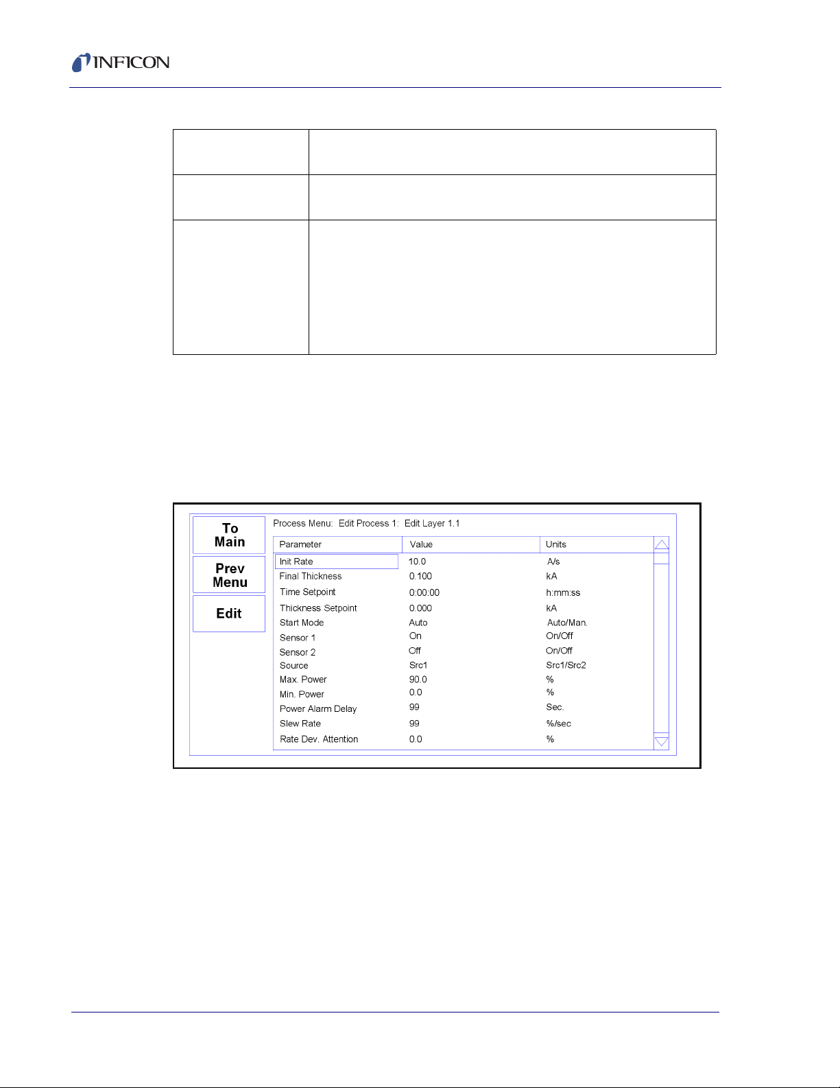
SQC-310 Operating Manual
Table 3-6 Layer Select Menu SoftKeys (continued)
Edit Displays the Layer Edit Menu for the highlighted layer (see the next
Insert New . . . Shows the list of 50 films. Select a film, then press Insert Normal or
Copy/Paste Used to develop the sequence of layers in a process.
3.7 Layer Edit Menu
Each layer consists of a film, plus the rate, thickness, and a few other parameters
needed for the layer. The Layer Edit Menu provides access to these layer
parameters. See Figure 3-5.
section).
Insert CoDep to insert the film as a new layer.
Copies the highlighted layer, which can then by pasted or inserted.
Pasting overwrites the highlighted layer. After copying, Insert also
becomes available. Insert pastes the layer in front of the highlighted
layer, see section 3.8, Layer Copy, Insert and Delete Menus, on
page 3-10.
Figure 3-5 Layer Edit Menu
IPN 074-550-P1B
3 - 8
Page 51

Table 3-7 Layer Edit Menu SoftKeys
SQC-310 Operating Manual
To
Main
Prev
Menu
Edit Selects the highlighted parameter for edit. SoftKey functions
Control Knob Scrolls through the list of layer parameters.
Returns to the Main Menu.
Returns to the Layer Select Menu.
change to:
Next: Store parameter and move to next for editing.
Cancel: Stop editing and undo changes to selected parameter.
Enter: Stop editing and save values for selected parameter.
Control Knob: Turn to adjust value. Push to store value and move
to next parameter.
A description of each parameter on the Layer Edit Menu follows:
Initial Rate: The beginning rate of deposition for this layer.This is the target rate
that the control loop tries to maintain througough the deposit (assuming no rate
ramps are used).
Final Thickness: The desired final thickness of this layer. The deposition phase of
this layer will end when this thickness is reached.
Time Setpoint: Sets an arbitrary time, after deposition begins, when the time
setpoint logic event becomes true.
Thickness Setpoint: Sets an arbitrary thickness when the thickness Setpoint logic
event becomes true.
Start Mode: Determines whether a layer begins automatically upon completion of
the previous layer. If Manual start is selected, the previous layer ends at its idle
power and waits for the user to press the Start button.
Sensor 1-4: Allows each quartz crystal Sensor to be selected for the selected film.
IPN 074-550-P1B
If multiple sensors are assigned to a film, their readings are averaged. If multiple
sensors are assigned to a film, and one fails, it is excluded from measurements.
Source: Selects the source output that is active for the selected layer.
Max. Power: The maximum output power allowed for the selected source. Power
is limited to this value and a power alarm occurs if the power remains at the
maximum for “Power Alarm Delay” seconds.
Min. Power: The minimum output power desired for the selected output. An alarm
occurs if power remains below this value for “Power Alarm Delay” seconds.
Power Alarm Delay: The time that source power must remain outside the Min/Max
Power settings to trigger an alarm.
3 - 9
Page 52

SQC-310 Operating Manual
Slew Rate: The maximum power change allowed on an output, per second. If
power or rate ramps exceed this value, an error will occur.
Rate Dev. Attention: The % rate deviation that triggers an attention alarm. The
default value of 0% disables this function.
Rate Dev. Alert: The % rate deviation that triggers an alert alarm. The default
value of 0% disables this function.
Rate Dev. Alarm: The % rate deviation that triggers an alarm. The default value of
0% disables this function.
Ramp 1: During the deposition of a layer, it may be desirable to change the
deposition rate. For example, you may want to deposit slowly at first, then increase
the rate once an initial thickness is reached. Enabling rate ramps provides that
capability. Once enabled, these parameters are added to the list.
Start Thickness: The deposited thickness at which the new rate will begin.
Ramp Time: Time allowed for the rate to change from initial rate to new rate.
New Rate: The rate of deposition, which is reached at the end of Ramp 1.
Ramp 2 / Ramp3: Three rate ramps are available for each layer. Ramps 2 and 3
both have Start Thickness, Ramp Time, and New Rate parameters similar to those
described above for Ramp 1. The start thickness for Ramp 2 should be greater than
the start thickness for Ramp 1. Likewise, the start thickness for Ramp 3 should be
greater than the start thickness for Ramp 2.
3.8 Layer Copy, Insert and Delete Menus
Copy, Delete and Insert are used to build and edit a sequence of process layers.
The Layer Select Menu, see Figure 3-6, shows a process consisting of four layers.
The first three layers will be co-deposited with Layer 1 (note the indentation of
layers 2 and 3). The fourth layer will be deposited after layers 1-3 are codeposited.
IPN 074-550-P1B
3 - 10
Page 53

SQC-310 Operating Manual
Figure 3-6 Layer Select Menu
To insert a new layer, scroll to the layer you want the new layer inserted above and
press Insert New. The Film Select menu allows you to select a film to be used for
this layer.
Figure 3-7 Film Select Menu
IPN 074-550-P1B
Once a film is selected, press Paste Normal or Paste CoDep. The Paste CoDep
option only appears when a valid layer has been selected for inserting. After the
paste, you are returned to the Layer Select menu.
3 - 11
Page 54

SQC-310 Operating Manual
Figure 3-8 Layer Select Menu
Highlight a layer and press Copy to store a copy of the layer in memory.
Figure 3-9 Copy Layer Menu
3 - 12
The display changes to the CopyLayer Menu. The Paste, Insert Normal, or Insert
IPN 074-550-P1B
CoDep SoftKeys may not be visible if the operation is not legal for the selected
layer.
Paste replaces the selected layer with the one stored in memory.
Remember that when Insert Normal or Insert Codep is used, layers are always
inserted above the highlighted layer. That is, the inserted layer will have the same
number as the highlighted layer, and the highlighted layer will move down one
layer.
HINT: When building a process it is easiest to add a “dummy” last layer and keep
inserting above that layer. When the process is complete, delete the
“dummy” layer.
Page 55

NOTE: Each CoDep layer must be assigned to a different output and sensor. A
3.9 Film Menus
Each film has certain characteristics that determine how it should be deposited.
The Film Menus allow you to set parameters that regulate the deposition of each
film. These parameters apply any time this film is used (in any process).
Figure 3-10 Film Select Menu
SQC-310 Operating Manual
warning message is displayed if there is a conflict. Highlight each CoDep
layer, press Edit, and assign unique sensors and outputs.
Table 3-8 Film Select Menu SoftKeys
Main Screen Returns to the Main Menu.
Edit Displays the Film Edit Menu for the highlighted film.
Edit Name Displays the character entry screen to edit the selected film name.
Delete Deletes the highlighted film. (Note: Films cannot be deleted if they
IPN 074-550-P1B
Copy/Paste Copies the highlighted film. Scroll to a film labeled as "<Empty>"
Create Available only when an undefined film (labeled as "<Empty>") is
are used in any process.)
and use Paste to paste the copied film.
highlighted. This button defines the empty slot as a film and assigns
it a film number, allowing it to be used in a process.
Press Edit to view the setup parameters for the selected film.
3 - 13
Page 56

SQC-310 Operating Manual
3.10 Film Edit Menu
Figure 3-11 Film Edit Menu
Table 3-9 Film Edit Menu SoftKeys
Exit to Main Returns to the Main Menu.
Prev
Menu
Edit Selects the highlighted parameter for edit. SoftKey functions
Film Conds. Displays pre/post conditioning settings (See section 3.10.1).
Deposit Controls Displays deposition control settings (See section 3.10.2).
Configure Sensors Displays crystal fail mode control settings (See section 3.10.3).
Returns to the Film Select Menu.
change to:
Next: Store parameter and move to next for editing.
Cancel: Stop editing and undo changes to selected parameter.
Enter: Stop editing and save values for selected parameter.
Control Knob: Turn to adjust value. Push to store value and
move to next parameter.
A description of each film parameter follows:
P Term: The proportional term sets the gain of the control loop. High gains yield
more responsive (but potentially unstable) loops. Try a value of 25, then gradually
increase/decrease the value to respond to step changes in rate setpoint.
I Term: The integral term controls the time constant of the loop response. Try 0.5
to 1 seconds for Ebeam systems, 5 to 10 for thermal systems.
IPN 074-550-P1B
3 - 14
D Term: The differential term causes the loop to respond quickly to changes. Use
0 or a very small value to avoid oscillations.
Page 57

SQC-310 Operating Manual
Film Tooling: Compensates for sensor sensitivity to the selected material. Use
Xtal Tooling in the System Parameters menu to compensate for each sensor
individually.
Pocket: Indicates which pocket of a multi-material indexer should be used. You
must first configure the Source in the Sources and Sensors screen of the System
Menu.
Crystal Quality, Rate Deviation: The maximum allowed rate deviation, from the
rolling average of the previous 16 rate readings. Each time the rate deviation
exceeds the selected percent value, a counter is incremented. Each time the
deviation is within the selected value, the counter decrements (to 0 minimum). If
the counter reaches Crystal Quality, Counts (see below) during a layer, the process
is aborted. Setting this value to zero disables the Crystal Quality alarm.
Crystal Quality, Counts: A counter is incremented each time Crystal Quality, Rate
Deviation is exceeded, then decremented each time a reading is within the rate
deviation. If the counter reaches Crystal Quality, Counts during a layer, the process
is aborted. Setting this value to zero also disables the Crystal Quality alarm.
NOTE: The Crystal Quality settings are very sensitive to PID loop tuning. It is best
to leave Crystal Quality disabled until you are confident of your process
and PID settings.
Crystal Stability, Single: As material is deposited on the crystal, the frequency
normally decreases. However arcing, mode hopping, or external stresses may
cause the crystal frequency to increase. If a single large positive shift exceeds this
value (in Hz) during a process, a crystal fail condition is indicated.
Crystal Stability, Total: As material is deposited on the crystal, the frequency
normally decreases. However arcing, mode hopping, or external stresses may
cause the crystal frequency to increase. If the accumulated value of these positive
frequency shifts exceeds this value (in Hz) during a process, a crystal fail condition
is indicated.
Material: Selects a material assigned to this film. As materials change, their
IPN 074-550-P1B
density and Z-Ratio are updated.
Density: Sets the density for this material. Material density has a significant impact
on deposition calculations.
Z-Factor: Sets the Z-Ratio, an empirically determined measure of a material’s
effect on quartz crystal frequency change.
3 - 15
Page 58

SQC-310 Operating Manual
3.10.1 Film Conditioning Menu
The Film Conditioning Menu contains the power settings used before and after
deposition. Definitions of each parameter appears later in this section.
Figure 3-12 Film Conditioning Menu
Ramp 1: Ramp power sets the power level (% of full scale) desired at the end of
the ramp phase. Ramp time sets the time to ramp linearly from the initial power to
the Ramp power. Soak time sets the time the output remains at the ramp power
level.
Ramp 2: Ramp 2 functions are the same as Ramp 1. Typically, Ramp 2 power is
set near the power level required to achieve the desired initial deposition rate.
Feed: The feed phase holds output power at the level and time required to wire
feed new material.
Idle: Idle power ramps output power back to zero, or holds the material at a state
that is ready for deposition (usually the same as Ramp 2 power).
IPN 074-550-P1B
3 - 16
Page 59

3.10.2 Film Deposit Controls Menu
The Deposit Controls Menu, see Figure 3-13, contains the settings used to control
shutters and instrument response during error conditions.
Figure 3-13 Deposition Controls Menu
SQC-310 Operating Manual
Shutter Delay: It is often desirable to obtain deposition control before the substrate
shutter opens. Enabling shutter delay requires that the system reach a specific
capture accuracy before the shutter opens. If the capture accuracy is not reached
within the shutter delay time, the process halts. Otherwise, the substrate shutter
opens and deposition begins when control accuracy has been maintained for 5
seconds. The thickness reading is zeroed at the end of the shutter delay period.
Capture: The control accuracy (%) that must be reached to end the shutter delay.
Control Delay: It is common to see a negative rate spike at the beginning of the
Deposit state when using a source or sensor with a shutter. This is due to the
sudden change in temperature that the crystal is exposed to when the shutter
opens. When the Control Delay function is used, the control loop will ignore the rate
for a set amount of time at the beginning of the Deposit state. This helps to
IPN 074-550-P1B
eliminate overcompensation by the control loop due to rate spikes when the sensor
or source shutter opens. The Control Delay setting is the amount of time the
SQC-310 will wait before the control loop takes over.
Control Error: If the control loop cannot maintain the desired deposition rate, due
to loss of source material, excess rate ramps, or equipment malfunction, a control
error occurs. The error condition can be ignored, the process stopped (output
power to 0%), or the output power held at the same level as when the error
occurred. If hold is selected, PID control is abandoned, but the process will
continue to be monitored for thickness setpoint.
3 - 17
Page 60

SQC-310 Operating Manual
Rate Sampling: Rate sampling can extend the life of crystals. With rate sampling,
the deposition rate is sampled for a period of time, then the sensor shutter is
closed. Power is then held at the same level as the final power setting during the
sample period.
Continuous selects no sampling; the sensor shutter remains open during
deposition.
Time based sampling opens the shutter for a fixed period of time, then closes
it for a fixed time.
Accuracy based sampling opens and closes the shutter at the rate required to
maintain the desired accuracy during the hold phase.
3.10.3 Film Configure Sensor Menu
The Configure Sensors Menu, see Figure 3-14, contains the settings used to
control crystal fail modes during error conditions.
Figure 3-14 Configure Sensors Menu
3 - 18
Crystal Fail Mode: The action that is executed if the sensor crystal fails.
Halt: The process will be halted in the event of a sensor failure.
Halt Last: The process will be halted if the last sensor of multiple assigned
sensors fails.
Timed Power: The current layer is completed based on the last power and rate
readings.
Switch to Backup:
The sensor is switched to the backup sensor (see below)
in the event of a sensor failure.
IPN 074-550-P1B
Page 61

Backup: This sensor is selected solely for use as a backup sensor. It may not
be used or selected as a sensor for a film but may be used in the event of a
sensor failure. Timed Power mode will be enabled if this is the last sensor to
fail.
Crystal Position: The desired crystal position in a multi-crystal sensor head.
Backup Sensor: The designated sensor is to be used as a backup in the event of
the main sensor failing. For example, if this setting is set to "2" under Sensor 1,
Sensor 2 will be used as a backup when Sensor 1 fails. This will automatically set
Snsr 2 Crystal Fail Mode to "Backup".
Backup Crystal Position: The position on the backup the sensor where the
backup crystal is located.
3.11 System Menu
The System Menu contains settings that affect the basic operation of the SQC-310.
System parameters generally pertain to the physical setup of your vacuum system
equipment.
SQC-310 Operating Manual
Figure 3-15 System Parameter Menu
IPN 074-550-P1B
3 - 19
Page 62

SQC-310 Operating Manual
Table 3-10 System Menu SoftKeys
To Main Returns to the Main Menu.
Edit Selects the highlighted parameter for edit. SoftKey functions
change to:
Next: Store parameter and move to next for editing.
Cancel: Stop editing and undo changes to selected parameter.
Enter: Stop editing and save values for selected parameter.
Control Knob: Turn to adjust value. Push to store value and move
to next parameter.
Input & Relays Displays menu for assigning inputs and relays.
Logic Menu Displays menu for building logic statements.
Sensors & Sources Displays menu for identifying sensor and source types.
Descriptions of each System Parameter follows:
Period
: Sets the measurement period between 0.1 second (10 readings per
second) and 1 second. A longer period gives higher reading accuracy, especially
in low rate and low density applications.
Period Frequency
(seconds)
Resolution (Hz)
.10 .03
.25 .01
.50 .005
.75 .004
1.00 .003
Simulate Mode: Normal mode uses the quartz crystals as inputs to the SQC-310
for PID calculations and source output control. Simulate mode simulates the quartz
crystals based on the crystal frequency min/max. Simulate mode is useful for
debugging process recipes but does not accurately mimic actual process control
performance.
System Tooling: Adjusts for overall sensor deposition rates that differ from the
measured substrate deposition rate.
IPN 074-550-P1B
3 - 20
Min/Max Frequency: The frequency values for the quartz crystal sensors used as
inputs to the SQC-310. The maximum frequency should be set to the frequency of
a new crystal, typically 6 MHz. Sensor readings outside the min/max values cause
an error.
Dev Graph Limit: Sets the upper limit for the Rate Deviation graph Y-axis.
Page 63

SQC-310 Operating Manual
CAUTION
Rate Filter Alpha: Establishes the amount of filtering done for rate display. Alpha
of 1 is no filtering. Alpha of 0.1 means that each new reading only represents 1/10
of the value displayed. The previous filtered value represents 9/10 of the displayed
value. Low alpha values give a very stable display, but will lag actual rate readings
and can hide noise problems.
RS-232 Comm: Baud rate used for RS-232 communications.
Password Enable: If Password is enabled, the Quick Start, Film and System
Menus require a password. The Process Menu can be used to select a process,
but a password is required to make any changes on the Process Menu.
Password: If password is enabled, this parameter sets the sequence of SoftKeys
to press to enter menus. Press the desired sequence to set the password. Refer to
figure Figure 3-16 on page 3-21 for an illustration of the password number
designations.
Figure 3-16 Password Number Designations
NOTE: Holding down SoftKeys 1 and 6 while powering up the SQC-310 sets the
password to 1111.
IPN 074-550-P1B
While holding down SoftKeys 1 and 6 during bootup will
reset the password, holding down 1, 6, and 7 (control
knob) will default memory for the entire system to the
factory settings. There is no way to reverse this, so be
sure you are holding down the correct buttons.
Alarm Sounds: Enabled/disables the audio alarm associated with alarm
conditions (most severe).
Alert Sounds: Enabled/disables the audio alarm associated with alert conditions
(less severe).
3 - 21
Page 64

SQC-310 Operating Manual
Attention Sounds: Enabled/disables the audio alarm associated with attention
conditions (least severe).
3.11.1 Input and Relay Menus
The Input and Relay Menus of the System Parameters Menu allow you to view and
customize relays and inputs.
Inputs and relays already assigned are indicated in the Use column by Snsr
(Sensor), Src (Source), or LS (Logic Statement).
This menu also displays the current state of each input or relay. Items in green are
currently active. Those is red are inactive.
The Relay selections have an additional SoftKey (Turn On Relay) that allows each
relay to be toggled manually for testing purposes, see Figure 3-17. Relays are
returned to their proper defined state on exit from this screen.
Figure 3-17 Relay Menu
3 - 22
IPN 074-550-P1B
Page 65

SQC-310 Operating Manual
Figure 3-18 Input Menu
To edit an Input or Relay, highlight it and press Select.
Editable Input parameters are:
Name: A logical name for this input. You can return to the input’s
system-defined default name by pressing the Set to Default SoftKey.
Active Level: The level, high (5 V) or low (0 V) that triggers the input.
Input Number: The physical input assigned to this logical input function. Alows
for re-assignment of inputs without physically re-wiring any inputs or
connectors.
Editable Relay parameters are:
Name: A logical name for this relay. You can return to the relay’s
system-defined default name by pressing the Set to Default SoftKey.
Type: Normally Open (NO) contacts or Normally Closed (NC) contacts. The
SQC-310 uses software to implement the NO/NC function. All relays are
IPN 074-550-P1B
actually normally open and will open when the SQC-310 is not powered.
Pulses: Selecting None causes the relay to activate when the logical relay
function is true, and deactivate when it is not. Some multi-crystal sensors
require one or two pulses for activation.
Pulse Width: The time (in seconds) that the relay activates if One or Two
Pulses are selected.
3 - 23
Page 66

SQC-310 Operating Manual
CAUTION
Relay Number: The physical output assigned to this logical relay function. This
allows for re-assignment of relays without physically re-wiring any relays or
connectors. Connector pins for these assignments are shown in Table 3-11.
Table 3-11 Relay & Input Connector Pin Assignments
Relay
Number
Relay 1 14,15 Input 1 16
Relay 2 1,2 Input 2 17
Relay 3 3,4 Input 3 18
Relay 4 5,6 Input 4 19
Relay 5 7,8 Input 5 20
Relay 6 9,10 Input 6 21
Relay 7 11,12 Input 7 22
Relay 8 13,25 Input 8 23
Connector
Pins
Input
Number
Ground 24
Connector
Pin
If changes are made in the Input or Relay Menu, be sure
to exit to the System Menu or Main Screen before
powering down. Your changes will not be saved
otherwise.
3 - 24
IPN 074-550-P1B
Page 67

3.11.2 Logic Menu
Logic statements allow you to program the SQC-310 to respond to inputs, and
activate relays, based on a variety of process conditions.
To create logic statements select System Menu, then Logic Menu. The logic
menu also displays the current state of each logic statement. Statements in green
are currently true. Those is red are false.
From the list of 32 logic statement names, scroll to a statement and select Edit to
view the Edit Logic screen. See Figure 3-19.
Figure 3-19 Edit Logic Screen
SQC-310 Operating Manual
Table 3-12 Edit Logic Screen SoftKeys
Go to
Name
Go to
Then
IPN 074-550-P1B
Go to
If
Delete Removes last condition in the logic statement.
Select Selects the highlighted condition for edit. SoftKey functions change
Moves cursor to the name field. Press Edit Name to display the
character input screen.
Moves the cursor to the THEN (action) part of the logic string. See
section 3.11.2.1 for a details on creating a logic statement.
Moves the cursor to the IF (condition) part of the logic string. See
section 3.11.2.1 for a details on creating a logic statement.
to:
Done: Returns to regular logic menu selections.
Delete: Removes last condition in selected logic statement.
Insert: Add the highlighted condition for current logic statement.
Control Knob: Turn to adjust value. Push to store value and move
to next parameter.
3 - 25
Page 68

SQC-310 Operating Manual
3.11.2.1 Entering a Logic Statement
A logic statement consists of two parts. The first part of the string (IF) indicates the
condition that must be satisfied. The second part (THEN) indicates the action that
takes place once the IF part has been satisfied.
To create a logic statement string you must follow three simple rules. For the IF
portion of the statement:
There must be an equal number of closed and open parentheses.
All conditions must be separated by an AND, OR, or NOT operator.
Condition strings cannot end in an operator.
Enter Logic Condition: To enter a logic condition, press Go to IF. Scroll down the
condition categories, and press Select to view the specific conditions for that
category. Scroll through the list of conditions and press Insert to add the condition
to the IF portion of the logic statement. Press Done to continue building the logic
statement.
To add another condition, you will need a logic operator such as AND, OR, NOT, or
a parenthesis. Scroll to the top of the condition categories, highlight Operators and
press select. Scroll to the desired operator and press Done. Enter another logic
condition as described above. Continue these operations until the desired IF
condition is built.
If you make a mistake, press Delete to delete the last entry in the IF statement.
Enter Logic Action: To enter a logic action, press Go to Then. Scroll down the
action categories, and press Select to view the specific actions for that category.
Scroll through the list of actions and press Insert to add the action to the THEN
portion of the logic statement. Press Done to complete the action portion of the
logic statement. Only one action is possible per logic statement.
When you exit the Edit Logic Statement screen, the statement is tested for proper
syntax. If there is an error, you are given the choice of correcting the statement. If
you chose to not correct errors, the logic statement will always evaluate as false.
Besides listing the names of the 32 logic statements, the Logic Menu shows the
current state of each statement. Statements that currently evaluate as true are
shown in green. Statements that evaluate as false are shown in red. This can be a
handy aid for troubleshooting logic statement and digital I/O problems.
3.11.2.2 Logic Statement Conditions ("IF")
Operators: For more complex logic statements logical operators such as AND,
OR, NOT, parentheses ( ), greater than >, and less than < can be added.
Parenthesis are used to group logic conditions, such as “IF (Input1 AND Input2)
OR Input3”. Every open parenthesis “(“ must have a matching closed parenthesis
“)”. The less than “<” and “>” than operators are used only with Timer conditions.
IPN 074-550-P1B
3 - 26
Page 69

SQC-310 Operating Manual
Numeric Values: Any integer between 1 and 64133. Numeric values are used with
timer conditions, such as IF Timer1 < 100 THEN Relay1.
Inputs: Choose the logic state (active state) of one the SQC-310 digital inputs as
a condition. If the specified input becomes active, the logic statement will become
true (choose input 1 - 16*)
Relays: Choose the logic state (active state) of one the SQC-310 relays as a
condition. If the specified relay becomes active, the the logic statement will become
true (choose relay 1 - 16*).
SoftNodes: SoftNodes allow you to build logic statements that are based on other
logic statements. There are 8 softnodes available for use.
For example, you might create a logic statement:
IF (Input1 AND Input2) OR Input3 THEN SoftNode1
You can now use that logic statement in another logic statement such as
If (SoftNode1 AND CrystalFail) THEN Stop Layer
Timers: The timer condition is evaluated true whenever the timer’s value is greater
than the value entered in the timer condition. There are 8 timers available for use.
Sensors: Allows you to choose between various sensor conditions. Available
sensor conditions include:
Sensor Enabled (choose sensor 1 - 4*)
Sensor Shutter (choose sensor 1 - 4*)
Sensor Fail (choose sensor 1 - 4*)
All Crystals Fail
All Crystals Good
Dual Crystal Shutter (choose dual sensor 1 or 2*)
Sensor Timeout (choose sensor 1 - 4*)
IPN 074-550-P1B
Sources: Allows you to choose between various source conditions. Available
source conditions include:
Source Enabled (choose source 1-4*)
Source Shutter (choose source 1-4*)
Source Timeout (choose source 1-4*)
Internal States: Allows you to choose an internal state as a condition. Available
states include:
Stopped
Crystal Verify
3 - 27
Page 70

SQC-310 Operating Manual
Initialized Layer
Manual Start Layer
Rotate Crystal
Rotate Pocket
Preconditioning
Soak Hold
Shutter Delay
Deposit
Timed Power Recovery
Crystal Switch
Next Crystal
Feed Ramp
Idle Ramp
Start Next Layer
Crystal Fail
Stop Layer
Snsor Feedback Timeout
Sorce Feedback Timeout
Sensor Feedback Error
Source Feedback Error
Invalid Crystal Position
Invalid Pocket Position
Internal Events: Allows the user to select an internal event as a condition.
Available events include:
Simulate
Manual Mode
Interlock
Last Layer
IPN 074-550-P1B
3 - 28
Process Hold
Process Active
Process Stopped
Shutter Delay Error
Page 71

SQC-310 Operating Manual
Thickness Setpoint
Final Thickness
Time Setpoint
Soak Hold
Rate Dev Alarm
Max Power Alert
Min Power Alert
Crystal Index: Allows you to select a specific crystal on a multi-crystal sensor as
a condition. Choose sensor 1 - 4* and crystal 1 - 16.
Pocket Index: Allows you to select a specific pocket on a multi-pocket source as
a condition. Choose source 1 - 4* and pocket 1 - 16.
Processes: The process condition is evaluated true whenever the selected
process is the current process. Choose process 1 - 100.
Layers: The layer condition is evaluated true whenever the current layer number
equals the specified layer number. Choose layer 1 - 100.
Films: The film condition is evaluated true whenever the current film number
equals the specified film number. Choose film 1 - 50.
NOTE: References to sensor 1 - 4, source 1 - 4, relay 1 - 16, or input 1 - 16 assume
the SQC-310 is equipped with the 4-channel option card. Units not
equipped with the option card will have sensor 1 - 2, source 1 - 2,
relay 1 - 8, and input 1 - 8.
3.11.2.3 Logic Statement Actions ("THEN")
General Actions: A selection of actions that do not fit into another category.
Available actions include:
No Action
IPN 074-550-P1B
Manual
Hold in State
Step From State
Interlock
Sensor & Sources: Actions related to moving multi-crystal sensors and
multi-pocket sources. Available actions include:
Switch Crystal (choose sensor 1 - 4*)
Move Snsr to Next Position (choose sensor 1 - 4*)
Move Src to Next Pocket (choose source 1 - 4*)
3 - 29
Page 72

SQC-310 Operating Manual
CAUTION
Relays: Activate one of the SQC-310 relays (choose relay 1 - 16*).
SoftNodes: Sets a Softened to true (choose softnote 1 - 8).
Timers: Start a timer (choose timer 1 - 8).
Alarms: Activate one of the SQC-310 alarms. Alarm options include:
Attention (least severe)
Alert (more severe)
Alarm (most severe)
Process Actions: Start or Reset current process, or select process 1 - 100.
Layer Actions: Perform an action on the current layer. Available actions include:
Start Layer
Start Next Layer
Stop Layer
Force Final Thickness
Zero Thickness
Zero Time
Soak Hold
If changes are made in the Logic Menu, be sure to exit to
the System Menu or Main Screen before powering down.
Your changes will not be saved otherwise.
IPN 074-550-P1B
3 - 30
Page 73

3.11.3 Sensors and Sources Menu
Substrate
Substrate
Tooling
Over 100%
Tooling
Under 100%
The Sensors and Sources Menu allows you to configure the SQC-310 to the types
of sensors and sources in your system, particularly multi-crystal sensors and
multi-pocket sources.
Figure 3-20 Sensor 1 Edit
SQC-310 Operating Manual
3.11.3.1 Sensor Setup
Crystal Tooling: Adjusts for the difference in measured deposition rate between
the sensor and the substrate being coated.
Figure 3-21 Tooling
IPN 074-550-P1B
In the left illustration, the sensor will measure less rate or thickness than is actually
deposited on the substrate because of its positioning. In the right illustration, the
sensor will measure more. Tooling is the ratio of the actual substrate deposition
rate or thickness, to that measured by the sensor. If the rate/thickness reading is
low, then increase the tooling value. If the rate/thickness reading is high, then lower
the tooling value.
3 - 31
Page 74

SQC-310 Operating Manual
Shutter: If the sensor has no shutter, select none to disable sensor shutter
features. If the sensor is a typical dual sensor, with a shutter that is only activated
when the primary sensor fails, select Dual. For other sensor shutters that activate
when the sensor is used, select Yes.
Shutter Delay: If the Yes option is selected for shutter, enter the time required
for the shutter to open and stabilize.
Number of Positions: This parameter defines the number of crystals available for
that sensor input. For single head sensors set to one. For a typical dual sensor
head with separate oscillators and sensor connections, this is also set to one
because there is only one crystal for each sensor input. For a rotary type
multi-crystal head set to the number of crystals available.
Current Position: If a multi-crystal sensor has position feedback, this
parameter is not needed. For sensors with only In Position or no position
feedback, enter the current crystal position.
Control Type: Defines the type of crystal or pocket position control utilized for
a multi-crystal sensor.
Manual: Not under control of the SQC-310. With manual control, the
SQC-310 will stop the process upon the completion of the current layer. If
the next layer requires a different crystal position. a message is displayed
prompting the operator for the number of the crystal required. Once the
position has been changed the operator presses the Continue SoftKey.
Direct: Used when the actuating device is driven directly. In this case the
controller creates one or two outputs, one for each available direction, to
drive a motor or solenoid.
Drive Type: Defines the drive method or direction for Direct control
Up, Down, Fast, and Inline: Select Up to create a single relay output
which the SQC-310 activates to increment the sensor to the next crystal
position. Down works identically, except the relay output is labeled
“Sensor Drive Down”. Select Fast to create both an up and down
outputs. The controller will then determine the fastest direction to the
target crystal position by activating the appropriate output. The Inline
drive type informs the controller that continuous travel in one direction
is not possible. Therefore to get from position 6 to 1, the direction must
be down through 5,4 etc. until 1 is reached.
Single Step and Double Step: Used when multi-crystal sensor heads
are actuated by pulsing a pneumatic value. INFICON CrystalSix uses
Double Step. INFICON Crystal12 and RSH-600 use Single Step.
IPN 074-550-P1B
3 - 32
Page 75

SQC-310 Operating Manual
BCD: Select when position control is through an external rotation controller
which accepts Binary Coded Decimal inputs for position selection. BCD
inputs are common because they require only a few signal lines to select
several positions. The SQC-310 automatically creates the number of relay
outputs required to interface with the external controller.
Individual: Select when position control requires a unique signal line for
each position. The SQC-310 automatically creates the number of relay
outputs required to interface with the external controller.
Feedback Type: Defines the type of feedback for a multi-crystal sensor head. This
is how the SQC-310 identifies the current crystal position.
None: No crystal feedback is provided. The SQC-310 tracks crystal position
from the current position setting (above). This setting is used for the INFICON
CrystalSix and Crystal12.
Individual: Uses one input for each pocket position in the source. All inputs are
normally false (open circuit) unless the respective pocket is in position when
that input is true (closed to ground). This setting is used for the INFICON
RSH-600.
BCD: Uses binary coding to indicate the pocket position. For example, an
eight-pocket source would use three inputs. With pocket one in position, all
inputs would be false. With pocket four in position, inputs one and two would be
true and input three would be false.
Single Home: This feedback indicates there is a single feedback signal that
indicates when pocket one is in position.
In Position: The input is normally false (open circuit) and goes true (closed to
ground) when any pocket is in position.
Indexer Delay: This parameter has two different functions. If the Feedback Type
is “None” the controller waits the designated time on the assumption that the pocket
will get into position by the end of the delay. If there is position feedback, the
controller will wait this time for the pocket to reach its target position. If it does not
IPN 074-550-P1B
receive the feedback signal, a Pocket Wait Timeout error is issued.
3 - 33
Page 76

SQC-310 Operating Manual
CAUTION
3.11.3.2 Source Setup
Source setup parameters are identical to the sensor setup parameters, with one
exception.
Voltage Scale: Sets the maximum output voltage for the source power supply
input. Voltages from –10 V to +10 V are possible. Your power supply manual will
state the required input voltage, typically 10 V, 5 V, -10 V, or –5 V.
If changes are made in the Logic Menu, be sure to exit to
the System Menu or Main Screen before powering down.
Your changes will not be saved otherwise.
3 - 34
IPN 074-550-P1B
Page 77

4.1 Introduction
WARNING
CAUTION
This section covers maintenance, cleaning, software upgrades, and the
installation of optional accessories.
4.2 Cleaning
SQC-310 Operating Manual
Chapter 4
Maintenance & Accessories
There are no adjustments or user-serviceable parts
inside the SQC-310 Series controllers. For maintenance,
contact INFICON.
Use a damp cloth, wetted with water or a mild detergent, to clean the outer
surfaces.
4.3 Software Upgrades
The SQC-310 firmware can be upgraded through its RS-232 port. Some
restrictions apply. Contact INFICON for instructions and availability of firmware
updates. Please record and have your firmware version and hardware version
(displayed at system startup) available when contacting INFICON for updates.
4.4 Clearing the Memory
The SQC-310 has two ways to clear system memory. Both involve pressing and
IPN 074-550-P1B
holding a combination of SoftKeys and the Control Knob. Figure 4-1 shows the
number designations given to each SoftKey and the Control Knob. These are the
same number designations used for entering system passwords. See section 3.11
for more information on passwords.
Memory clearing procedures cannot be reversed. Be sure
to back up your configuration file using SQC-310 Comm
software if possible before attempting to clear system
memory.
4 - 1
Page 78

SQC-310 Operating Manual
Figure 4-1 SoftKey Number Designations
To clear all memory except or the material index, press and hold the #1 and #6
SoftKeys along with the Control Knob (#7) during startup. On the bootup screen the
following should be displayed:
Loading Materials. . . . . . . . . . . . Failed!
Loading Films. . . . . . . . . . . . . . . Failed!
Loading System . . . . . . . . . . . . . Failed!
Loading Processes. . . . . . . . . . . Failed!
Once the SQC-310 boots up, turn the power off and back on again. Now the
SQC-310 should load normally and should display:
Loading Materials. . . . . . . . . . . . Done
Loading Films. . . . . . . . . . . . . . . Done
Loading System . . . . . . . . . . . . . Done
Loading Processes. . . . . . . . . . . Done
If any "Failed!" messages still appear during loading, turn the power off and back
on again. Only "Done" messages should appear after memory clearing is
complete.
To clear all memory except the material index and set the SQC-310 back to factory
default, press and hold the #2 and #5 buttons along with the Control Knob (#7)
during startup. All loading messages will now display "Failed!", except Materials.
Repeat the rebooting procedure described above until all loading messages
display "Done".
IPN 074-550-P1B
4 - 2
Page 79

4.5 Half Rack Adapter Installation
The optional Half Rack Adapter kit (PN 782-900-016) mounts two SQC-310
instruments side by side in a standard 19 in. rack.
The Half Rack Adapter kit consists of two standard rack mount ears and an adapter
bracket. Attach one of the standard rack mount ears to each SQC-310 with the
10-32 flat head screws supplied. Connect the two SQC-310 instruments together
by place them side by side and installing the adapter bracket to their back panels
using the existing screw holes. You will need to remove one screw from each back
panel to make these holes available. Attach the assembly to the 19 in. rack using
two screws on each side (not included).
4.6 Full Rack Extender Installation
The Full Rack Extender option (PN 782-900-007) mounts an SQC-310 into a full
width 19 in. rack space.
Assemble the two 3 in. x 5 in. Extender Kit side panels and the larger front and rear
panels into a box configuration using the eight 6-32 flat-head screws.
SQC-310 Operating Manual
Figure 4-2 Attaching the Extender
IPN 074-550-P1B
Thread two 10-32 shoulder screws from the inside of one of the box sides until the
threads extend fully to the outside. Now attach the Extender Kit to the SQC-310 by
threading the shoulder screws into the matching holes in the SQC-310 covers.
4 - 3
Page 80

SQC-310 Operating Manual
ABORT
Sigma
instrum ents
Handheld Controller
Attach the rack mounting ears with the 10-32 flat-head screws provided. Carefully
lift the assembly into a full width, 5¼ in . high rack space. Attach the assembly to
the rack with 10-32 screws (not provided).
4.7 Handheld Remote Controller
The Handheld Controller (PN 782-900-017) provides the capability of adjusting
output power remotely when the SQC-310 is in Manual Mode.
Figure 4-3 Handheld Remote Controller
To use the handheld controller, attach the cable from the handheld controller to the
Remote jack on the SQC-310 front panel. Select a Process using the SQC-310
front panel SoftKeys. Press Next Menu until the Auto/Manual SoftKey is displayed.
Press Auto/Manual to change to Manual power mode (SoftKey shows
Manual/Auto). Press Start to begin the film deposition.
You can now use either the front panel Control Knob or the Handheld Controller to
adjust output power. Pressing Abort on the handheld controller stops the layer and
returns output power to 0%.
IPN 074-550-P1B
4 - 4
Page 81

5.1 Introduction
The SQC-310 communicates with a host computer through three possible
protocols:
RS-232: 19200 to 115200 baud, 8 data bits, and no parity
USB: PID 8292
Ethernet (option): Port 2101, Address 192.168.1.200.
5.2 SQC-310 Comm.exe
SQC-310 Comm.exe is found on the 074-5000-G1 Thin Film Instrument and
Sensor Manuals CD supplied with your SQC-310.
SQC-310 Operating Manual
Chapter 5
Communications
The program provides real-time instrument control and process data logging. It
also allows you to set process, layer, film, and material parameters, download them
to the SQC-310 and save them to disk.
NOTE: SQC-310’s with firmware Version 5.01 and earlier are not compatible with
SQC-310 Comm. For these older units, please use SQC-300 Comm
(Version 4.xx). Contact INFICON for more information.
5.2.1 Communications Protocol
The SQC-310 only responds to commands received. It never initiates
communications.
The command protocol sent to the instrument is:
IPN 074-550-P1B
sync character> <length character> <1 to n data characters> <CRC1><CRC2>
The sync character is always an exclamation point ‘!’. Following the sync character
is the length character. This is the number of characters in the packet (not counting
the sync, length, and CRC characters). The length character has a decimal 34
added to it so there cannot accidentally be a sync character (!) embedded in the
packet.
Following the length character are the command and data characters as detailed
later in this section. After the data come two CRC characters.
NOTE: If you do not want to use CRC checking in your application, send two Null
characters (CHR$0) for the CRC. The SQC-310 will ignore the CRC. The
SQC-310 will still return a CRC in its response, but you can ignore it.
5 - 1
Page 82

SQC-310 Operating Manual
The CRC is computed using the following algorithm:
1 The CRC is initialized to 3FFF hex.
2 Each character in the message is examined, bit by bit, and added to the CRC
in the following manner:
2a The character is exclusive OR’d with the CRC.
2b The CRC is shifted right one bit position.
2c If bit position 0 has a value of 1 before each shift, the CRC is exclusive OR’d
with 2001 hex. This is done a total of 8 times per message character.
3 Step 2 is repeated for each character in the message (excluding the sync and
length characters).
4 Mask the contents of the CRC by logical AND with 3FFF hex.
5 The CRC contains 14 significant bits. This is split into two pieces of 7 bits each.
A decimal 34 (22 hex) is added to each CRC in order to avoid there being an
embedded sync character.
5a Extract bits 0 - 6 of the CRC and add a decimal 34 (22 hex). This is CRC1.
5b Extract bits 7 - 13 of the CRC and add a decimal 34 (22 hex). This is CRC2.
NOTE: Sync characters are not included in the CRC calculation.
Code examples for calculating the CRC can be found in section 5.4, CRC
Examples, on page 5-18.
Once a command is received by the SQC-310, it responds with a Response Status
character as shown in Table 5-1.
Table 5-1 Response Status Characters
Response Status Meaning
A Command understood, normal response
B Command understood, but instrument reset
C Invalid command
D Problem with data in command
E Instrument in wrong mode for this command
If the response status is “A”, the requested data follows the status character.
IPN 074-550-P1B
5 - 2
Page 83

5.3 SQC-310 Commands
5.3.1 Get Model
Command: . . . . . @
Description: . . . . Returns the model number and software version number.
Parameters: . . . . None
Example: . . . . . . The @ command returns “SQC-310 Ver 6.01”
5.3.2 Get/Set Film Parameters
Command: . . . . . A
Description: There are four film commands. A1 sets/gets the film
name. A2 sets/gets the main film edit screen parameters. A3
sets/gets the film conditioning parameters. A4 sets/gets the
deposit controls parameters.
To Get Film Parameters send the command (i.e., A1), a space,
the film number, a question mark, then a series of spaces and
parameter numbers. You may include as many parameters as
you want, in whatever order you want. The format of the return
string is a series of parameter numbers, a comma, and its value,
separated by spaces.
SQC-310 Operating Manual
To Set Film Parameters send the command, a space, the film
number, then a series of parameter numbers, a comma, and the
parameter value.
Parameters: . . . . A1: FilmName
A2: 1 P Term 7 Crystal Quality, Rate Dev %
2 I Term 8 Crystal Stability, Single Freq Shift
3 D Term 9 Xtal Fail Mode (obsolete)
4 Material # 10 Crystal Quality, Max Count
IPN 074-550-P1B
5 Pocket* 11 Crystal Stability, Total +Freq Shift
6 Tooling
A3: 1 Ramp1 Power 7 Idle Power
2 Ramp1 Time 8 Idle Ramp
3Soak1 Time 9Feed Power
4 Ramp2 Power 10 Feed Ramp
5 Ramp2 Time 11 Feed Time
6Soak2 Time
5 - 3
Page 84

SQC-310 Operating Manual
A4: 1 Shutter Delay 5 Rate Sampling (0,1,2)
2 Capture 6 Sample Accuracy
3 Control Error (0,1,2) 7 Sample Hold
4 Control Percent 8 Sample Time
A5: 1 Snsr 1 Crystal Fail Mode 9 Snsr 3 Crystal Fail Mode
2 Snsr 1 Crystal Position 10 Snsr 3 Crystal Position
3 Snsr 1 Backup Sensor 11 Snsr 3 Backup Sensor
4 Snsr 1 BackupXtalPosition 12 Snsr 3 BackupXtalPosition
5 Snsr 2 Crystal Fail Mode 13 Snsr 4 Crystal Fail Mode
6 Snsr 2 Crystal Position 14 Snsr 4 Crystal Position
7 Snsr 2 Backup Sensor 15 Snsr 4 Backup Sensor
8 Snsr 2 BackupXtalPosition 16 Snsr 4 BackupXtalPosition
Example: . . . . . . To Get the PID parameters of Film 1, send: A2 1? 1 2 3
The return string would be of the form: 1,50 2,5 3,0
To Set the PID parameters of Film 1, send: A2 1 1,50 2,5 3,0
NOTE: Numeric film parameter values sent and received by
the SQC-310 are integers. To convert between the
integer value and the parameter’s actual value, you
must multiply or divide by the number of decimal digits
in the displayed parameter.
In the examples above, the P term is displayed as an integer
value, so no conversion is required. However, the I Term is
displayed with one decimal digit (i.e., 0.5). A Get response of 5
actually represents a parameter value of .5. Similarly, a Set
value of 5 for the I Term sets its value in the SQC-310 to .5.
IPN 074-550-P1B
5 - 4
Page 85

5.3.3 Get/Set System Parameters
Command: . . . . . B
Description: . . . . Gets/Sets the system parameters screen values. The format is
similar to Get/Set Film Parameters. See the examples below.
Parameters: 1 Period 11 Scale 4 (obsolete)
2 System Tooling 12 Xtal Tool 3 (obsolete)
3 Xtal Tool 1 (obsolete) 13 Xtal Tool 4 (obsolete)
4 Xtal Tool 2 (obsolete) 14 Alarm Sounds
5 Simulate Mode 15 Alert Sounds
6 Min. Frequency 16 Attention Sounds
7 Max. Frequency 17 Rate Dev Graph Limit
8 Scale 1 (obsolete) 18 Password Enabled
9 Scale 2 (obsolete) 19 Password
10 Scale 3 (obsolete) 20 RateFilterAlphaValue
Example: . . . . . . To Get the Xtal Tool 1 and Xtal Tool 2, send: B? 3 4
The return string would be of the form: 3,100 4,100
SQC-310 Operating Manual
To Set the parameters you would send: B 3,100 4,100
Command: . . . . . BA
Description: . . . . Switch the graphs/displays on the main screen.
Parameters: 1 Display Rate vs. Time Graph
2 Display Rate Deviation vs. Time Graph
3 Display Power vs. Time Graph
4 Display Large Format Screen
Format: . . . . . . . . BA [Parameter]
IPN 074-550-P1B
Example: . . . . . . BA 1
Returns: A
Command: . . . . . BB
Description: . . . . Turns the remote mode on or off. Remote mode ignores all local
user input such as button presses.
Parameters: 1 Turn Remote Mode: Off
2 Turn Remote Mode: On
Format: . . . . . . . . BB [Parameter]
Example: . . . . . . BB 1
Returns: A
5 - 5
Page 86

SQC-310 Operating Manual
5.3.4 Get/Set Process Parameters
Command: . . . . . C
Description: . . . . Gets/sets the four process parameters. In the parameter list
below, Number Layers is the number of layers in a process,
counting CoDep layers as 1 layer. Actual Layers is the total
number of layers. For example, a process with one CoDep layer
(using two films) would have Number Layers=1 and Actual
Layers=2.
The First Layer is the layer number of the first layer in the
process. Subsequent layers are found by reading the Next
Layer parameter (see the D command, Layer Parameters).
Parameters: 1 Process Name 3 First Layer
2 Number Layers 4 Actual Layers
Example: . . . . . . To Get Process 1 name, send: C1? 1
The return string would be of the form: AnyName
To Set the parameter, send: C1 1,AnyName
NOTE: Unlike Get/Set Film Parameters, you can only get/set
one process parameter at a time.
Command: . . . . . CA
Description: . . . . Performs a process specific command.
Parameters: 1 Create A New Process
2 Delete A Process
3 Delete All Layers In This Process
4 Check This Process (1 is ‘process is OK’)
Format:. . . . . . . . CA[Process#]? [Parameter]
Example: . . . . . . CA1? 1
Returns: A1,1
Command: . . . . . CB
Description: . . . . Performs a process & layer location specific command.
Parameters: 1 Cut this Layer from this Process
Format:. . . . . . . . CB[Process#] [LayerPosition#]? [Parameter]
Example: . . . . . . CB1 2? 1
Returns: A1,1
IPN 074-550-P1B
5 - 6
Command: . . . . . CC
Description: . . . . Performs a process, layer location & film specific command.
Page 87

Parameters: Insert a NonCoDep Layer in this Process
Insert a CoDep Layer in this Process.
Format: . . . . . . . . CC[Process#] [LayerPosition#] [Film#]? [Parameter]
Example: . . . . . . CC1 2 9? 1
Returns: A1,1
5.3.5 Get/Set Layer Parameters
Command: . . . . . D
Description: . . . . Most layer parameters are directly related to a setting on the
layer edit screen. You can get/set multiple layer parameters as
explained in Film Parameters.
Parameters: 1 Init Rate 16. Ramp1 Time
2 Final Thickness 17. Ramp2 Enable
3 Time SetPoint 18. Ramp2 Start
4 Thickness Limit 19. Ramp2 Rate
SQC-310 Operating Manual
5 Start Mode 20. Ramp2 Time
6 Output 21. Film Number
7 Max. Power 24. Layer Available
8 Slew rate 25. Min. Power
9 Sensor 1 26. Power Alarm Dev (sec.)
10 Sensor 2 27. Rate Dev. Attention
11 Sensor 3 28. Rate Dev. Alert
12 Sensor 4 29. Rate Dev. Alarm
13. Ramp1 Enable
14. Ramp1 Start
15. Ramp1 Rate
IPN 074-550-P1B
Command: . . . . . DA
Description: . . . . Gets/Sets the parameters for the given layer as specified by the
given process number, layer number in the process, and the
assigned source number.
Parameters: (same as above)
1 Init Rate 16. Ramp1 Time
2 Final Thickness 17. Ramp2 Enable
3 Time SetPoint 18. Ramp2 Start
4 Thickness Limit 19. Ramp2 Rate
5 Start Mode 20. Ramp2 Time
5 - 7
Page 88

SQC-310 Operating Manual
6 Output 21. Film Number
7 Max. Power 24. Layer Available
8 Slew rate 25. Min. Power
9 Sensor 1 26. Power Alarm Dev (sec.)
10 Sensor 2 27. Rate Dev. Attention
11 Sensor 3 28. Rate Dev. Alert
12 Sensor 4 29. Rate Dev. Alarm
13. Ramp1 Enable
14. Ramp1 Start
15. Ramp1 Rate
Format:. . . . . . . . DA[Process#] [LayerInProcess#] [Source#]? [Parameter1]
[Parameter2] …
Example: . . . . . . DA1 1 1? 1 2
Returns: A1,50 2,501
Command: . . . . . DB
Description: . . . . Gets the layer that is currently running or set to run next if not
Parameters: 1 Current Layer’s Layer Numbers
Format:. . . . . . . . DB? [Parameter1] [Parameter2] …
Example: . . . . . . DB? 1 2 3 4
5.3.6 Delete All Layers
Command: . . . . . E
Description: . . . . Deletes all 1000 layers! Most often used to clear the entire
Parameters: . . . . None
currently running a layer.
2 Current Layer’s NonCoDep Position In Process
3 Current Layer’s NonCoDep Position(s) In Process With Source Num
4 Current Layer’s CoDep Positions In Process
Returns: A1,20:21:22:19 2,2 3,2.1:2.2:2.3:2.4 4,5:6:7:8
IPN 074-550-P1B
instrument in preparation for downloading a new list.
5 - 8
Page 89

5.3.7 Get/Set Material Parameters
Command: . . . . . F
Description: . . . . Gets/Sets the parameters of the 100 stored materials.
Parameters: 1. Material Name 3. Zfactor
2. Density
Example: . . . . . . To Get Material 1 name, send: F1? 1
The return string would be of the form: Aluminum
To Set the parameter you would send: F1 1,AnyName
NOTE: You can only get/set one material parameter at a time.
5.3.8 Get/Set Input & Relay Parameters
Command: . . . . . G
Description: . . . . Gets/Sets the logical function of each of the 16 digital inputs.
Parameters: 1 Start Process 32 Soak Hold
2 Abort Process 33 Zero Thickness
3 Start Layer 34 Zero Time
SQC-310 Operating Manual
4 Stop Layer 35 Out1 Pocket Ready
5 Start Next Layer 36 Out2 Pocket Ready
6 Force Final Thick 37 Out3 Pocket Ready
7-31 Start Process 1-25 38 Out4 Pocket Ready
39 Not Used
Example: . . . . . . To Get Input 1 and Input 2 functions, send: G? 1 2
The return string for Start Layer and Stop Layer would be:
1,3 2,4
To Set the same parameters you would send: G1 1,3 2,4
Command: . . . . . GA
IPN 074-550-P1B
Description: . . . . Gets/Sets the parameters of each of the 8 or 16 digital inputs.
Parameters: 1 Name 3 Pin Number
2 Active Level 4 Input In Use *
5 NameMode
Format: . . . . . . . . GA[Input#]? [Parameter1] [Parameter2] …
Example: . . . . . . GA1? 2 3
Returns: !A2,0 3,1
NOTE: When changing the name (GA1), you MUST also send
the Name Mode command (GA5) as the next
parameter.
5 - 9
Page 90

SQC-310 Operating Manual
Command: . . . . . GB
Description: . . . . Gets/Sets the parameters of each of the 8 or 16 digital relays.
Parameters: 1 Name 4 Pulse Width (milliseconds)
2 Type (N.O. or N. C.) 5 Pin Number
3 Pulses 6 Relay In Use *
7 NameMode
Format:. . . . . . . . GB[Relay#]? [Parameter1] [Parameter2] …
Example: . . . . . . GB1? 2 5
Returns: !A2,0 5,1
NOTE: When changing the name (GB1), you MUST also send
the Name Mode command (GB7) as the next
parameter.
Command: . . . . . GC
Description: . . . . Gets the current state of each of the 8 or 16 digital relays and
inputs.
Parameters: 1 Current Relay State (off=0, on=1)
2 Current Input State (off=0, on=1)
Format:. . . . . . . . GC[RelayOrInput#][?] [Parameter1] [Parameter2] …
Example: . . . . . . GC1? 1 2
Returns: A1,0 2,1
Command: . . . . . GD
Description: . . . . Override the current relay state for one of the 8 or 16 digital
relays. Overriding the relay is only available while the instrument
is stopped. If a relay is accidentally left on, the relay is turned off
at the start of a new process.
Parameters: 1 Override Relay: Turn On
2 Override Relay: Turn Off
Format:. . . . . . . . GD[Relay#] [Parameter1]
Example: . . . . . . GD1 1
Returns: A
Command: . . . . . GE
Description: . . . . Allows any relay that is not controlled by a Logic Statement,
Sensor or Source, to be set remotely. Once a relay’s state has
been set remotely, that relay is locked and the instrument will not
allow it to be controlled via a Logic Statement Action, Sensor or
Source. Be sure to unlock the relay after it is no longer needed;
doing so will also turn the relay off.
IPN 074-550-P1B
5 - 10
Page 91

SQC-310 Operating Manual
Parameters: 1 Turn Relay: On (locks relay for remote use only)
2 Turn Relay: Off (locks relay for remote use only)
3 Unlock Relay (Releases the Relay back to the Instrument)
Format: . . . . . . . . GE[Relay#] [Parameter1]
Example: . . . . . . GE1 1
Returns: A
5.3.9 Get/Set Sensor, Source, Relay Parameters
Command: . . . . . H (obsolete)
Description: . . . . Gets/Sets the logical function of each of the 16 relays.
Parameters: 1 Source 1 Shutter 21 Max. Power
2 Source 2 Shutter 22 Stopped
3 Source 3 Shutter 23 Time Setpoint
4 Source 4 Shutter 24 Thick Limit
5-8 Sensor 1-4 Shutter 25 Final Thickness
9-12 Sensor 1-4 Fail 26 Dual Xtal 1/2 Shutter
13 All Crystals Good 27 Dual Xtal 3/4 Shutter
14 All Crystals Bad 28-35 Out1 Pocket 1-8
15 Process Hold 36-43 Out1 Pocket 1-8
16 Deposit Phase 44-51 Out1 Pocket 1-8
17 PreCond Phase 52-59 Out1 Pocket 1-8
18 SoakHold Phase
19 Process Active
20 Manual Mode
Example: . . . . . . To Get Relay 1 and Relay 2 functions, send: H? 1 2
IPN 074-550-P1B
The return for Source 1 Shutter and Sensor 1 Shutter would be:
1,1 2,5
To Set the same parameters you would send: H1 1,1 2,5
Command: . . . . . HA
Description: . . . . Gets/Sets the parameters of each of the 2 or 4 sensors.
Parameters: 1 Crystal Tooling 6 Drive Type
2 Number of Positions 7 Feedback Type
3 Shutter 8 Indexer Delay (sec.)
4 Shutter Delay (ms) 9 Current Crystal Position
5 Control Type
5 - 11
Page 92

SQC-310 Operating Manual
Format:. . . . . . . . HA[Sensor#]? [Parameter1] [Parameter2] …
Example: . . . . . . HA1? 2 5 9
Returns: !A2,4 5,3 9,1
Command: . . . . . HB
Description: . . . . Gets/Sets the parameters of each of the 2 or 4 sources.
Parameters: 1 Voltage Scale 6 Drive Type
2 Number of Positions 7 Feedback Type
3 Shutter 8 Indexer Delay (sec.)
4 Shutter Delay (ms) 9 Current Pocket Position
5 Control Type
Format:. . . . . . . . HB[Source#]? [Parameter1] [Parameter2] …
Example: . . . . . . HB1? 2 5 9
Returns: !A2,4 5,3 9,1
Command: . . . . . HC
Description: . . . . Gets the status flags for each of the 2 or 4 sensors.
Parameters: 1 Dual Crystal has Switched 6 Sensor is currently in use
2 Backup Crystal Switch has begun 7 Next Crystal Move Complete
3 Backup Crystal Switch is done 8 Sensor Initiated Time Power
4 Sensor is Disabled 9 Sensor Initiated Halt
5 Original Crystal has failed
Format:. . . . . . . . HC[Sensor#]? [Parameter1] [Parameter2] …
Example: . . . . . . HC1? 5 6
Returns: A5,1 6,0
Command: . . . . . HD
Description: . . . . Gets the status flags for each of the 2 or 4 sources.
Parameters: 1 Source is currently in use
Format:. . . . . . . . HD[Source#]? [Parameter1]
Example: . . . . . . HD1? 1
Returns: A1,1
Command: . . . . . HE*
IPN 074-550-P1B
5 - 12
Description: . . . . Gets/Sets the IO mappings of each of the 2 or 4 sensors.
Parameters: 1 Input Map* 2 Relay Map*
Format:. . . . . . . . HE[Sensor#]? [Parameter1] [Parameter2] …
Page 93

Example: . . . . . . HE1? 1 2
Returns: !A1,0:0:0:0:0:0:0:0:0:0:0:0:0:0:0:0
2,0:0:0:0:0:0:0:0:0:0:0:0:0:0:0:0
Command: . . . . . HF*
Description: . . . . Gets/Sets the IO mappings of each of the 2 or 4 sources.
Parameters: 1 Input Map* 2 Relay Map*
Format: . . . . . . . . HF[Source#]? [Parameter1] [Parameter2] …
Example: . . . . . . HF1? 1 2
Returns: !A1,0:0:0:0:0:0:0:0:0:0:0:0:0:0:0:0
2,0:0:0:0:0:0:0:0:0:0:0:0:0:0:0:0
5.3.10 Get/Set Logic Statement Parameters
Command: . . . . . I
Description: . . . . Gets/Sets the parameters of each of the 32 logic statements.
Parameters: 1 Name (16 chars)* 4 If Condition Syntax Valid (get only)
SQC-310 Operating Manual
2 If Condition(max 16) * 5 IfCondition CurrentState (get only)
3 Then Action * 6 LS Defined
Format: . . . . . . . . I[LogicStatement#]? [Parameter1] [Parameter2] …
Example1: . . . . . I1? 1 2 3
Returns: A1,Statement 1 2,201:3:202 3,301
Example2: . . . . . I1 1,LS 1 2,202:3:201 3,302
Returns: A
Command: . . . . . IA
Description: . . . . Copy and Pastes a Logic Statement from one index to another.
Parameters: . . . . None
IPN 074-550-P1B
Format: . . . . . . . . IA[LogicStatement#ToCopyFrom] [LogicStatement#ToCopyTo]
Example: . . . . . . IA1 5
Returns: A
Command: . . . . . IB
Description: . . . . Deletes a Logic Statement.
Parameters: . . . . None
Format: . . . . . . . . IB[LogicStatement#]
Example: . . . . . . IB1
Returns: A
5 - 13
Page 94

SQC-310 Operating Manual
5.3.11 Get Num Channels
Command: . . . . . J
Description: . . . . Returns the number sensor/output channels installed.
Parameters: . . . . None
Example: . . . . . . The J command returns either 2 or 4.
5.3.12 Get Readings
Command: . . . . . K
Description: . . . . Returns the phase time and sensor or output readings for all
Parameters: . . . . 1 = Output Readings2 = Sensor Readings
Example: . . . . . . To Get Output readings, send: K1
installed channels.
The return string is of the form:
Time Rate1 Dev1 Thick1 Power1 Rate2 Dev2 Thick 2 etc.
Command: . . . . . K3
5.3.13 Get Sensor Rate
Command: . . . . . L
Description: . . . . Returns the sensor rate for the requested sensor.
Parameters: . . . . Sensor Number
Example: . . . . . . To Get Sensor 1 rate, send: L1
To Get Sensor readings, send: K2
The return string is of the form:
Time Rate1 Thick1 Frequency1 Rate2 Thick 2 etc.
Same as K but will respond with an error if there are not new
sensor readings since the last time the command was sent.
Used primarily for the testing the instrument.
IPN 074-550-P1B
The return string is of the form: 1.00
5 - 14
Page 95

5.3.14 Get Output Rate
Command: . . . . . M
Description: . . . . Returns the average rate of all sensors assigned to the
requested output.
Parameters: . . . . Output Number
Example: . . . . . . To Get Output 1 rate, send: M1
The return string is of the form: 1.00
5.3.15 Get Sensor Thickness
Command: . . . . . N
Description: . . . . Returns the thickness reading for the requested sensor.
Parameters: . . . . Sensor Number
Example: . . . . . . To Get Sensor 1 thickness, send: N1
The return string is of the form: 1.000
SQC-310 Operating Manual
5.3.16 Get Output Thickness
Command: . . . . . O
Description: . . . . Returns the average thickness of all sensors assigned to the
requested output.
Parameters: . . . . Output Number
Example: . . . . . . To Get Output 1 thickness send: O1
The return string is of the form: 1.000
5.3.17 Get Sensor Frequency/Crystal Life
IPN 074-550-P1B
Command: . . . . . P
Description: . . . . Returns the frequency of the requested sensor.
Parameters: . . . . Sensor Number
Example: . . . . . . To Get Sensor 1 frequency, send: P1
The return string is of the form: 5543210.00
Command: . . . . . PA
Description: . . . . Returns the status, frequency, and crystal life of the requested
sensor.
Parameters: . . . . Sensor Number
5 - 15
Page 96

SQC-310 Operating Manual
Example: . . . . . . To Get Sensor 1 info, send: PA1
The return string is of the form:
status frequency life
where status 0=inactive,1=active
For example: 1 5950000.00 95.00
5.3.18 Get Output Deviation
Command: . . . . . Q
Description: . . . . Returns the % deviation of the requested output.
Parameters: . . . . Output Number
Example: . . . . . . To Get Output 1 deviation, send: Q1
The return string is of the form: 1.00
5.3.19 Get/Set Output Power
Command: . . . . . S
Description: . . . . Returns output power. Sets outputs to PID loop mode or manual
Parameters: . . . . Output Number, Power
Example: . . . . . . To Get Output 2 power send: S? 2
5.3.20 Set Active Process
Command: . . . . . T
Description: . . . . Sets the currently selected process. If a process is running, it is
Parameters: . . . . Process Number
mode. In manual mode, also sets the output power. Power is
sent as an integer value.
To Set Output 2 to 50.0% of full scale send: S2 500
NOTE: This places other outputs in Manual mode at their
current power.
To set all outputs to PID loop control send: S0
IPN 074-550-P1B
not changed and an E response status is returned.
5 - 16
Example: . . . . . . To set the process to Process 1 send: T1
Page 97

5.3.21 Set Run State
Command: . . . . . U
Description: . . . . Sets the instruments operating state.
Parameters:
Example: . . . . . . To start the active process, send: U0
5.3.22 Get Run State
Command: . . . . . V
SQC-310 Operating Manual
0 = Start Process 32 = Zero Thickness
1 = Stop Process 33 = Zero Time
2 = Start Layer 38 = SoakHold Enable
3 = Stop Layer 39 = SoakHold Disable
4 = Next Layer
5 = Force Final Thickness
Description: . . . . Returns the Phase #, Process Elapsed Time (as shown on
display), Process #, and Active Layer of the active process.
Parameters:
0 = Stopped 13 = Deposit 26 = Manual Power
1 = Crystal Verify 14 = Rate Ramp 27 = Snsr Feedback Timeout
2 = Initialize Layer 15 = Rate Ramp Deposit 28 = Src Feedback Timeout
3 = Manual Start Layer 16 = Timed Power 29 = Invalid Crystal Position
4 = Crystal Rotate 17 = Rate Sample Hold 30 = Invalid Pocket Position
5 = Pocket Rotate 18 = Rate Sample 31 = Sample Hold
6 = PreCond (CoDep only)19 = Crystal Switch 32 = Sampel Continuous
7 = Ramp1 20 = Feed Ramp 33 = Crystal Fail, Halted
IPN 074-550-P1B
8 = Soak 1 21 = Feed Soak 34 = Next Crystal
9 = Ramp 2 22 = Idle Ramp
10 = Soak 2 23 = Start Next layer
11 = Soak Hold 24 = Crystal Fail
12 = Shutter Delay 25 = Stop Layer
Example: . . . . . . To read the run state, send: V
The return string for the Deposit Phase, Elapsed Time =15
seconds, Active Process #1, Layer #2 is: 13 15 1 2
Command: . . . . . VA
Description: . . . . Gets the on/off status of each possible alarm.
5 - 17
Page 98

SQC-310 Operating Manual
Parameters:
1 Alarm: MinRate&MaxPower 15 Alert: Min Power
2 Alarm: MaxRate&MinPower 16 Alert: Logic Statement Action
3 Alarm: ShutterDelayError 17 Attention: Crystal Failure
4 Alarm: Crystal Failure 18 Attention: Xtal Failed & Xtal Switched
5 Alarm: Source Timeout 19 Attention: Rate Deviation
6 Alarm: Sensor Timeout 20 Attention: Max Power
7 Alarm: No Sensors Enabled 21 Attention: Min Power
8 Alarm: In Time Power 22 Attention: Manually Move Source
9 Alarm: Rate Deviation 23 Attention: Manually Move Sensor
10 Alarm: Invalid Pocket 24 Attention: Interlock
11 Alarm: Invalid Crystal 25 Attention: Logic Statement Action
12 Alarm: Logic Sttmnt Action
13 Alert: Rate Deviation
14 Alert: Max Power
Format:. . . . . . . . VA? [Parameter1] [Parameter2] …
Example: . . . . . . VA? 1 2 3
Returns: A1,0 2,0 3,1
5.3.23 Start Download/Upload Session
Command: . . . . . XSTART
Description: . . . . Starts a upload/download session & places in the instrument in
remote mode. The instrument must be Stopped in order to start
an upload/download session.
Parameters:
5.3.24 Stop Download/Upload Session
Command: . . . . . XSTOP
Description: . . . . Stops an upload/download session & kicks the instrument out of
remote mode.
Parameters:
IPN 074-550-P1B
5.4 CRC Examples
In this section you will find examples of code for calculating the CRC in Visual
Basic, Java, and C++. Instructions for calculating the CRC are located in section
5.2.
5 - 18
Page 99

SQC-310 Operating Manual
5.4.1 Visual Basic® 5/6
Public Sub CalcChkSumByte(ByRef ByData() As Byte, ByRef byCRC() As
Byte)
Dim CRC As Integer
Dim TmpCRC As Integer
Dim LastIndex As Long
Dim i As Integer
Dim j As Integer
LastIndex = UBound(ByData())
' Avoid on length messages
If ByData(1) > 0 Then
' Set 14 bit CRC to all ones
CRC = &H3FFF
For j = 1 To LastIndex - 2
' XOR current character with CRC
CRC = CRC Xor ByData(j)
' Go thru lower 8 bits of CRC
For i = 1 To 8
' Save CRC before shift
TmpCRC = CRC
' Shift right one bit
CRC = Shri(CRC, 1)
If (TmpCRC And 1) = 1 Then
' If LSB is 0 (before shift), XOR with hex 2001
CRC = CRC Xor &H2001
End If
Next i
Next j
' Be sure we still have 14 bits
CRC = CRC And &H3FFF
byCRC(0) = (LoByte(CRC) And &H7F) + 34
IPN 074-550-P1B
byCRC(1) = (LoByte(Shri(CRC, 7)) And &H7F) + 34
Else
' Empty message
byCRC(0) = 0
byCRC(1) = 0
End If
End Sub
Public Function LoByte(ByVal intNumber As Integer) As Byte
' Comments : Returns the low byte of the passed integer
' Parameters: intNumber - integer value for which to return the low
byte
' Returns : byte
5 - 19
Page 100

SQC-310 Operating Manual
' Source : Total VB SourceBook 6
'
On Error GoTo PROC_ERR
LoByte = intNumber And &HFF&
PROC_EXIT:
Exit Function
PROC_ERR:
MsgBox "Error: " & Err.Number & ". " & Err.Description, , _
"LoByte"
Resume PROC_EXIT
End Function
Public Function Shri( _
ByVal lngValue As Long, _
ByVal bytPlaces As Byte) _
As Integer
' Comments : Shifts a long Value right the selected number of places
' Parameters: lngValue - integer Value to shift
' bytPlaces - number of places to shift
' Returns : Shifted value
' Source : Total VB SourceBook 6
'
Dim lngDivisor As Long
On Error GoTo PROC_ERR
' if we are shifting 16 or more bits, then the result is always
zero
If bytPlaces >= 16 Then
Shri = 0
Else
lngDivisor = 2 ^ bytPlaces
Shri = Int(IntToLong(lngValue) / lngDivisor)
End If
PROC_EXIT:
Exit Function
IPN 074-550-P1B
5 - 20
PROC_ERR:
MsgBox "Error: " & Err.Number & ". " & Err.Description, , _
"Shri"
Resume PROC_EXIT
End Function
 Loading...