

Page 1

SID-242
Thin Film Deposition Controller
SQS-242
Deposition Control Software
Version 3.00
User’s Guide
© Copyright Sigma Instruments, Inc. 1998-2002
Page 2

Sigma
instruments
Page 3
Safety Information
Read this manual before installing, operating, or servicing equipment. Do not install
substitute parts, or perform any unauthorized modification of the product. Return the
product to Sigma Instruments for service and repair to ensure that safety features are
maintained.
Safety Symbols
WARNING: Calls attention to a procedure, practice, or condition that could
possibly cause bodily injury or death.
C
AUTION: Calls attention to a procedure, practice, or condition that could
possibly cause damage to equipment or permanent loss of data.
Refer to all manual Warning or Caution information before using this product
to avoid personal injury or equipment damage.
Hazardous voltages may be present.
Earth ground symbol.
Chassis ground symbol.
Equipotential ground symbol.
Page 4

Warranty Information
This Sigma Instruments product is warranted against defects in material and
workmanship for a period of 2 years from the date of shipment, when used in
accordance with the instructions in this manual. During the warranty period, Sigma
Instruments will, at its option, either repair or replace products that prove to be
defective.
Limitation of Warranty
Defects from, or repairs necessitated by, misuse or alteration of the product, or any
cause other than defective materials or workmanship are not covered by this warranty.
NO OTHER WARRANTIES ARE EXPRESSED OR IMPLIED, INCLUDING BUT NOT
LIMITED TO THE IMPLIED WARRANTIES OF MERCHANTABILITY AND FITNESS
FOR A PARTICULAR PURPOSE. UNDER NO CIRCUMSTANCES SHALL SIGMA
INSTRUMENTS BE LIABLE FOR CONSEQUENTIAL OR OTHER DAMAGES
RESULTING FROM A BREACH OF THIS LIMITED WARRANTY, OR OTHERWISE.
Return Policy
The purchaser may return this product in new condition within 30 days after shipment
for any reason. In case of return, purchaser is liable and responsible for all freight
charges in both directions.
Sigma Instruments
120 Commerce Drive, Unit 1
Fort Collins, CO 80524 USA
970-416-9660
970-416-9330 (fax)
Page 5

Table of Contents
Chapter 1 Introduction
1.0 SID-242 Introduction ........................................................................................1-1
1.1 SRC Series Computer ......................................................................................1-1
1.2 SQM-242 Deposition Control Card ...................................................................1-2
1.3 SQS-242 CoDeposition Control Software ........................................................1-2
1.4 Digital I/O .........................................................................................................1-3
Chapter 2 Quick Start
2.0 Introduction ......................................................................................................2-1
2.1 Installation ........................................................................................................2-1
2.2 Front Panel ......................................................................................................2-2
2.3 Program Startup ...............................................................................................2-3
2.4 Single Layer Process Setup .............................................................................2-4
2.5 Single Layer Process Simulation ......................................................................2-8
2.6 SoftKey Functions ............................................................................................2-10
2.7 Multi-Layer CoDeposition Process ...................................................................2-11
2.8 Conclusion .......................................................................................................2-15
Chapter 3 SQS-242 Software
3.0 Introduction ......................................................................................................3-1
3.1 Installation and Registration .............................................................................3-2
3.2 Operation .........................................................................................................3-2
3.3 File Menu .........................................................................................................3-4
3.4 Edit Menu .........................................................................................................3-5
3.4.1 Processes....................................................................................................3-6
Layers .....................................................................................................3-7
Rate Ramps ............................................................................................3-9
Deposition ...............................................................................................3-10
Conditioning ............................................................................................3-12
Sources and Sensors ..............................................................................3-13
3.4.2 Films ............................................................................................................3-15
3.4.3 Materials ......................................................................................................3-16
Page 6

Chapter 3 SQS-242 Software (continued)
3.4.4 System ........................................................................................................3-17
Sensors ...................................................................................................3-17
Sources ...................................................................................................3-18
Digital I/O .................................................................................................3-19
PLC Setup ...............................................................................................3-22
SQM-242 Setup .......................................................................................3-23
RS232 Setup ...........................................................................................3-24
3.4.5 Security .......................................................................................................3-25
3.5 View Menu .......................................................................................................3-27
3.6 Specifications ...................................................................................................3-28
Chapter 4 SQM-242 PC Card
4.0 Introduction ......................................................................................................4-1
4.1 Installation ........................................................................................................4-2
4.2 Sensor Connections .........................................................................................4-4
4.3 Power Supply Connection ................................................................................4-4
4.4 TroubleShooting ...............................................................................................4-4
4.5 Demo Programs ...............................................................................................4-7
4.6 SQM32C.DLL ...................................................................................................4-7
4.7 Specifications ...................................................................................................4-7
Chapter 5 Digital I/O
5.0 Introduction ......................................................................................................5-1
5.1 PLC Installation ................................................................................................5-2
5.2 PLC Setup and Test .........................................................................................5-3
5.2 PLC Programming ............................................................................................5-4
Chapter 6 Computer Interface
6.0 Introduction ......................................................................................................6-1
6.1 Serial Interface .................................................................................................6-1
6.2 Ethernet Interface .............................................................................................6-1
6.3 SQS-242 Comm Program ................................................................................6-2
6.4 Protocol ............................................................................................................6-3
6.5 Command Summary ........................................................................................6-5
Appendix
A. Material Parameters
B. Loop Tuning
Page 7

Page 8
Chapter 1 Introduction
1.0 Introduction
This manual covers both the hardware and software associated with the SID-242 Thin
Film Deposition Controller. The SID-242 consists of four main elements, integrated into
a complete deposition control system:
SRC Series Rack-mount Computer
SQM-242 PC Card(s)
SQS-242 Windows CoDeposition Software
PLC for Digital I/O (option)
While the focus of this manual is on the SID-242 Controller package, it also covers each
of these components separately. If you have purchased only the SQS-242 Software
and/or the SQM-242 Card, we suggest that you also review Chapters 1 and 2 of this
manual for important information.
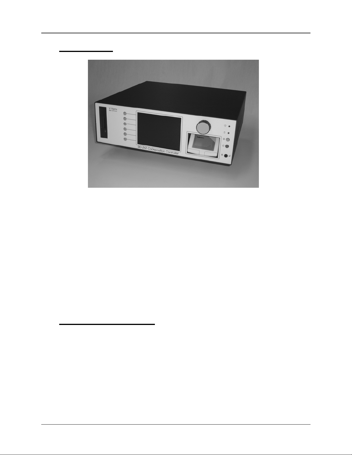
1.1 SRC Series Computer
Sigma’s SRC Series computers are Celeron (or better) class computers running the
Windows operating system. The SRC computer series uses standard off-the-shelf
components and Sigma’s custom rack-mount chassis to provide a compact, low cost
instrument.
Included in the 5.25” or 7” high rack-mount chassis are an LCD Display, a TouchPad
pointing device, a setting Knob, and six SoftKeys. A keyboard is provided for initial
setup, but is not necessary for normal operation of the SQS-242 deposition control
software. An optional rack-mount keyboard is also available.
1-1
Page 9
Chapter 1 Introduction
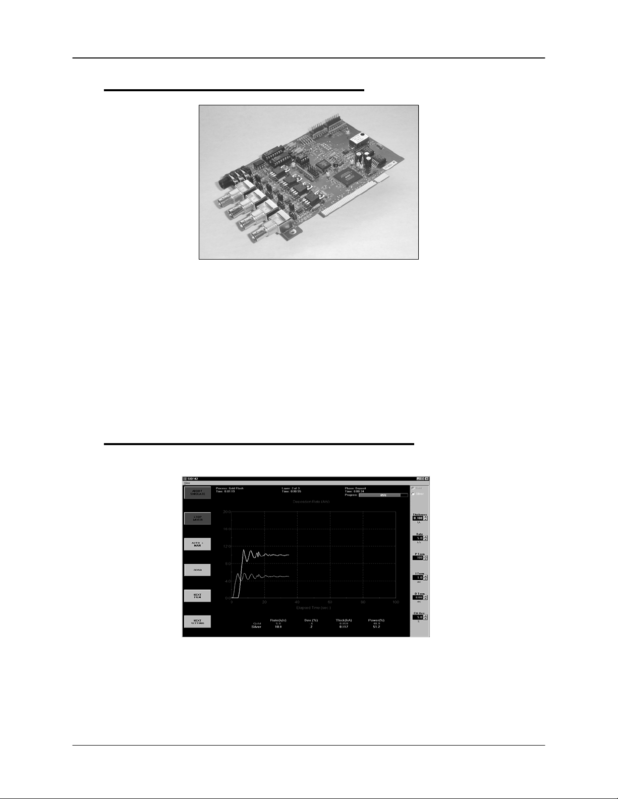
1.2 SQM-242 Deposition Control Card
Sigma’s SQM-242 is a PCI expansion card for use in computers running the Windows
operating system. Each card measures up to four quartz sensors via BNC inputs, and
supplies the control signal for two evaporation sources via a dual phone plug output.
Up to two cards can be installed in a computer, creating an eight input, four output,
codeposition controller.
The SQM-242 card is supplied with demonstration software written in Visual Basic and
LabView, including complete source code. The SQM-242 card and a Windows based
computer form a basic deposition control system (without digital I/O capabilities).
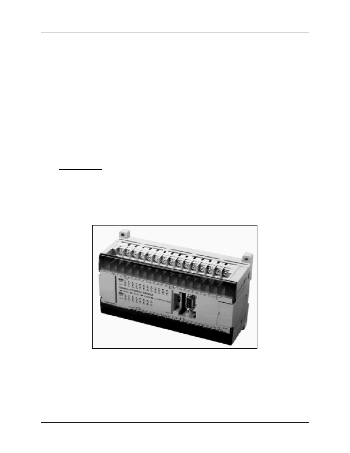
1.3 SQS-242 CoDeposition Control Software
Included with the SID-242 is Sigma’s SQS-242 software, a Windows-based program
that provides all of the functions required for an eight sensor, four output, codeposition
controller. It is optimized for use with the Setting Knob and six SoftKeys of our SID-242
controller. However, it will run on any Win98 or later system with our SQM-242 card
installed.
1-2
Page 10
Chapter 1 Introduction
The six SoftKeys provide easy access to the common operating functions. A single
tabbed dialog box provides all of the settings required for a thin film process. Material
parameters, sensor/source setup, pre/post conditioning, and error conditions are all
visible on a single screen. Process settings, numeric data, and graphical displays are
displayed during all phases of deposition.
The SQS-242 software stores process parameters in a Microsoft Access compatible
database. This provides virtually unlimited access to desktop tools for building and
analyzing thin film processes.
The SQS-242 software can be controlled from another computer using the RS-232 or
Ethernet command protocol.
1.4 Digital I/O
Digital I/O for the SID-242 is provided through an inexpensive, external, programmable
logic controller (PLC). This allows the PLC, and the associated I/O wiring, to be placed
in a convenient location in a wiring cabinet. A single, serial communications cable runs
to the SID-242 computer. The PLC provides electrical isolation, fail-safe operation, and
extensive I/O processing capabilities through its ladder logic programming.
1-3
Page 11

Chapter 1 Introduction
This page left blank for your notes.
1-4
Page 12

Chapter 1 Quick Start
1-1
Page 13

Chapter 2 Quick Start
2.0 Introduction
This section covers the minimum system connections and initial setup required to run
the SID-242 Deposition Controller. Consult later chapters of this manual for more
detailed setup and operational instructions.
2.1 Installation
All electrical connections to the SID-242 are made at the back panel of the instrument.
WARNING: Care should be exercised to route SID-242 cables as far as practical from
other cables that carry high voltages or generate noise. This includes other line voltage
cables, wires to heaters that are SCR-controlled, and cables to source power supplies
that may conduct high transient currents during arc down conditions.
Rack
Installation
Power
Connection
Sensor Input
Connections
Source Output
Connections
Digital I/O
Connections
Keyboard
Connection
The SID-242 occupies a 5.25” high (4U) rack space. Install the
unit in a 19” rack with the supplied hardware.
W
ARNING: Verify that the Voltage Selector Switch, located next
to the power switch, matches your mains supply voltage.
WARNING: Verify that the power cable provided is connected to
a properly grounded mains receptacle.
Connect the BNC cables and oscillators from your vacuum
chamber feedthrough to the desired SQM-242 Card Input(s).
Refer to Chapter 4 for detailed instructions on system hookup
to the SQM-242 card(s).
Connect the dual phone plug from the SQM-242 output jack to
your evaporation supply control input. Refer to Chapter 4 for
detailed instructions on wiring the SQM-242 output phone plug.
Digital I/O is not required for initial operation of the SID-242.
Perform initial setup and checkout of the SID-242 before
connecting your digital I/O. Refer to Chapter 5 for detailed
information on wiring the SID-242 for digital I/O.
A keyboard is supplied for initial user setup of Windows.
Attach the keyboard to the keyboard input jack on the rear of
the SID-242. Once Windows is setup, use of the keyboard is
optional.
2-1
Page 14
Chapter 2 Quick Start
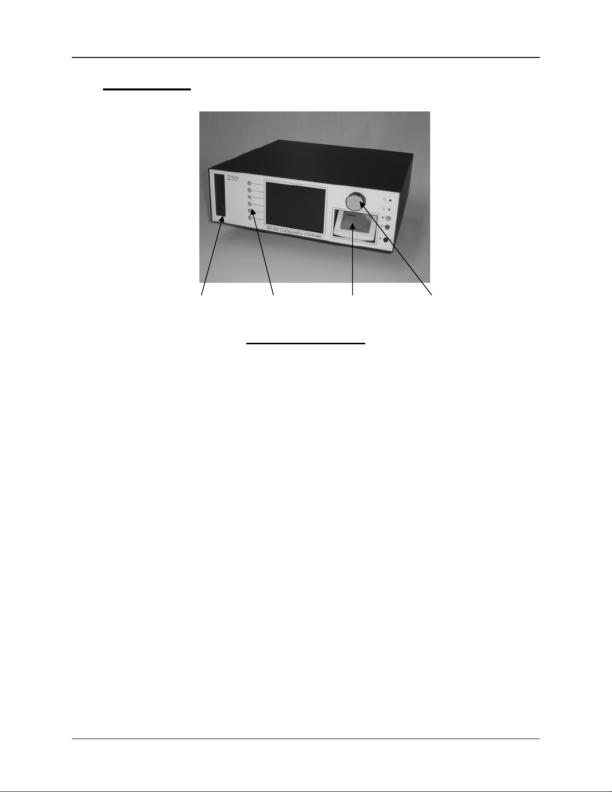
2.2 Front Panel
Floppy Disk SoftKeys TouchPad Control Knob
Front Panel Controls
KeyLock
SoftKeys
TouchPad
Control
Knob
Floppy
Disk
Keyboard
(not shown)
Insert key and turn clockwise to enable the power and reset
buttons. Turn counterclockwise to disable the power and reset.
Provide basic instrument operations within the SQS-242
deposition program. The SoftKeys are functional only in
programs written specifically for the SRC computer.
Provides mouse functions in all Windows programs, including
the SQS-242 software. Move your index finger along the
touchpad surface to move the cursor. Press the left or right
buttons below the touchpad surface to “click.”
Used to adjust values within the SQS-242 software. Pushing
the control knob stores the current setting, and moves to the
next setting. Functional only in programs written specifically for
the SRC computer.
1.44 MB floppy disk for upgrades, backup, and data
storage/transfer.
Required for Windows data entry, and useful during initial SID242 setup. Not required for SQS-242 software operation. The
F1 through F6 keys on the keyboard provide the same
functions as the six SoftKeys on the front panel.
2-2
Page 15

Chapter 2 Quick Start
2.3 Program Startup
This section will start the SID-242 and run the SQS-242 deposition control program.
Power On the
Computer
Start the
Program
User Login
Screen
Process
Database
Main Display
Insert the and turn clockwise to enable the power and reset
buttons. Push the power button to start the computer.
The SID-242 will boot Windows from the internal disk and start
the SQS-242 deposition program. If the SQS-242 program
does not start automatically, use the touchpad to double-click
the desktop icon.
Note: If you are prompted to register the software, just press
Cancel for now.
Note: The SID-242 ships with one pre-assigned user. The
user name is Super, with no Password.
The SID-242 displays a progress bar during program startup,
then a User Login screen. Select a User Name from the drop
down box, enter the Password, then click OK.
See Chapter 3 for more information on users, passwords, and
access levels and registartion.
The SID-242 normally starts with the last active process
database. If that database is not found, a Database Open
dialog will be displayed. Use the touchpad to navigate to the
desired database.
The main display shows a set of labels associated with the
function of the six SoftKeys. As you operate the SID-242,
these labels will change to display appropriate functions.
Along the top of the display is a menu of less commonly used
functions. This menu is available only when the SID-242 is
stopped (i.e. not running a deposition process).
2-3
Page 16

Chapter 2 Quick Start
Simulate Mode
Simulate mode allows you to familiarize yourself with SID-242
operation, and test process recipes. If the first SoftKey is
labeled “START SIMULATE” then the Simulate mode is active.
If the first SoftKey is labeled “START PROCESS" then normal
mode is selected. Use the touchpad to select the Setup menu,
then click System. On the SQM-242 tab, click the Simulate
option button. Click the “Save” SoftKey label, or press the top
SoftKey to activate Simulate mode.
2-4
Page 17
Chapter 2 Quick Start
2.4 Single-Layer Process Setup
A thin-film deposition process consists of one or more layers of material evaporated
onto a substrate. Let’s build a simple single-layer process.
Open
Process Edit
Add A New
Process
Edit
Film
Edit Rate and
Thickness
Use the touchpad to click on the “Edit” menu selection along
the top of the display, then click “Process.” The Process Edit
dialog will display the setup for the last process run.
To better understand process setup, see section 3.4.1.
Click the “New” button in the dialog box. An on-screen
keyboard appears, displaying the next numbered Process.
Click “Backspace” several times to delete the name. Now
“type” a new Process name using the touchpad and on-screen
keyboard. Click “Enter” to save the new name.
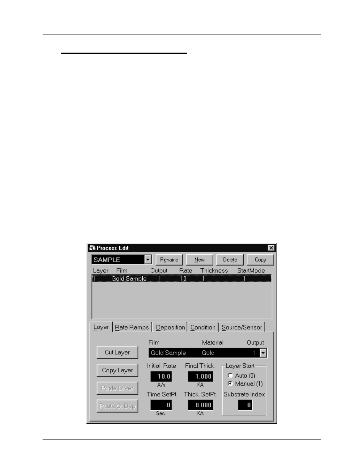
Click the “Layer” tab to assure the layer parameters are
displayed. Select “Gold Sample” in the Film dropdown box.
Click the “Initial Rate” setting, and then use the Control Knob to
adjust the Initial Rate to 10 Å/s. Adjust the “Final Thickness” to
1.000 kÅ.
2-5
Page 18
Chapter 2 Quick Start
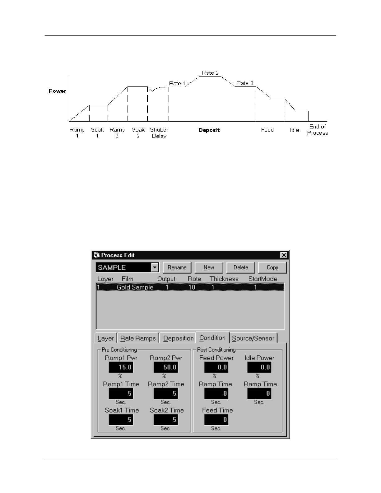
The diagram below illustrates a complete deposition cycle for a single layer. Refer to
this diagram as we set the remaining process setup parameters.
Edit
Rate Ramps
Edit Pre/Post
Conditioning
It may be desirable to vary the deposition rate during a layer.
For example, to deposit slowly at first, then more quickly once
the initial material is deposited. Click the “Rate Ramps” tab,
then click “Insert Ramp.” Adjust the “Start Thickness” to 0.400
kÅ, “Ramp Time” to 5 seconds, and “New Rate” to 15 Å/s.
Before deposition begins, the source material is often brought
to a ready state by raising the evaporation source power.
Select the “Condition” tab and set each parameter to the
values shown below.
2-6
Page 19
Chapter 2 Quick Start
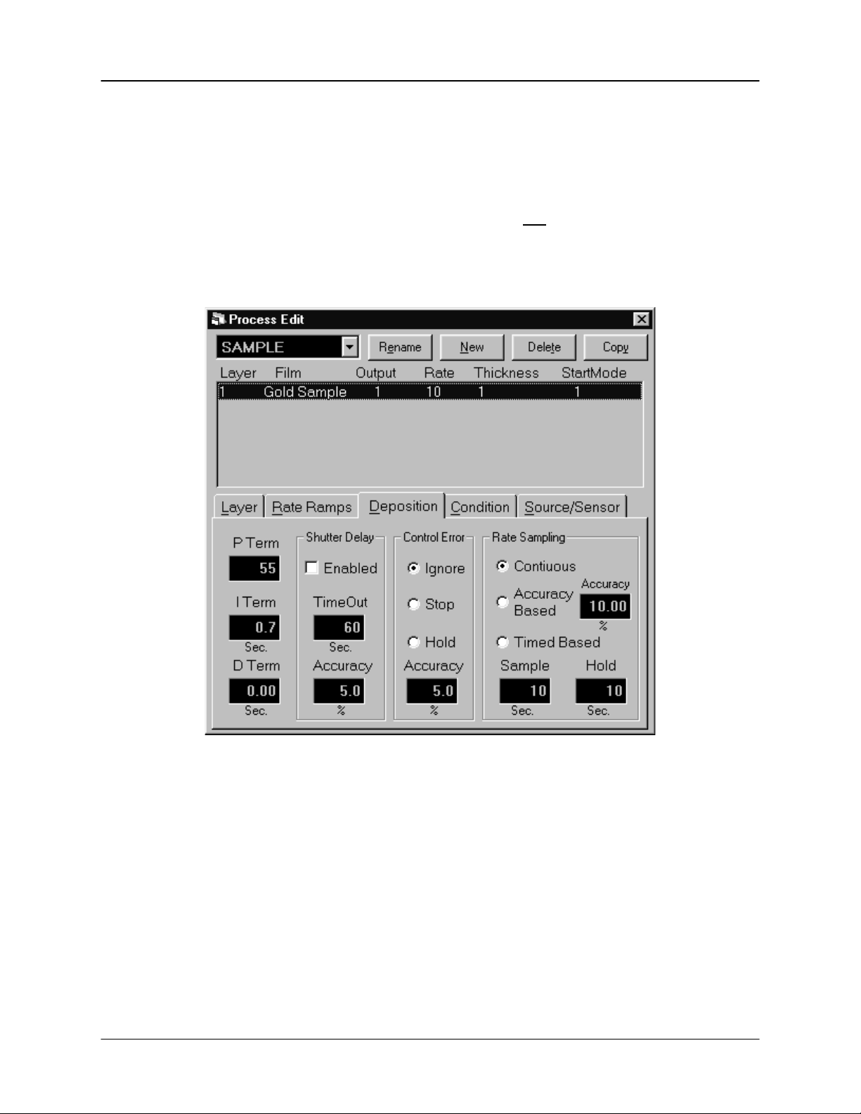
Edit
Deposition
Select the “Deposition” tab. This tab establishes the gain (P
Term), time constant (I Term), and dead time (D Term) for your
process. Set these values to 55, .7, and 0 respectively.
Be sure Shutter Delay Enabled is not selected. Select Ignore
for Control Error, and Continuous for Rate Sampling (see
picture below).
2-7
Page 20
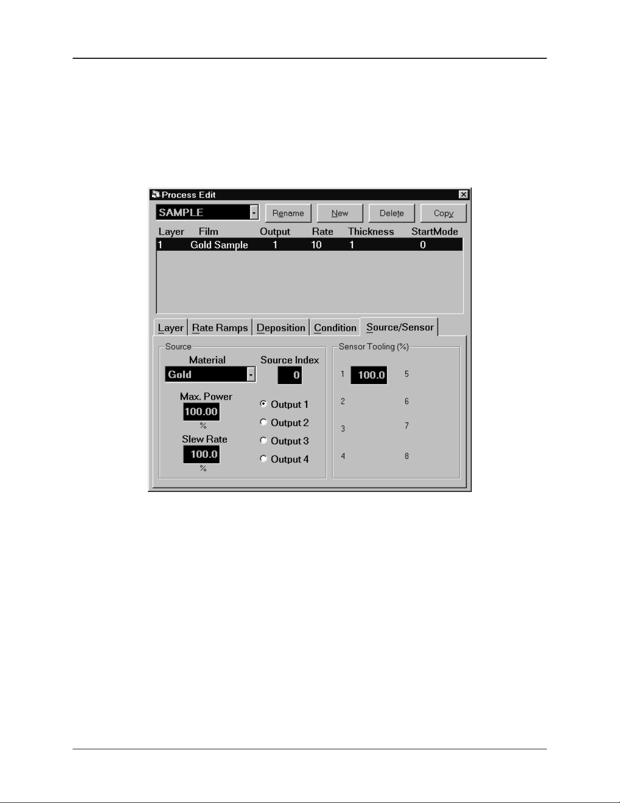
Chapter 2 Quick Start
Edit
Source/Sensor
Select the “Source/Sensor” tab. This tab contains parameters
associated with the physical layout of your evaporation system.
For now, be sure that “Output 1” is selected and “Max Power”
and “Slew Rate” are set to 100. Set the “Tooling” value to 100.
Leave the Source Index as it is.
Save Edits
Your new single-layer process is now the active process in the main window. Notice the
process, layer, and time information above the graph.
Click “Close Form” or press the first SoftKey to save this onelayer process. If you are prompted “Do you want to
change….,” answer Yes to make this the current process.
2-8
Page 21
Chapter 2 Quick Start
2.5 Single-Layer Process Simulation
If you have followed this chapter, you are ready to simulate a deposition process.
Setup
Displays
Start
Process
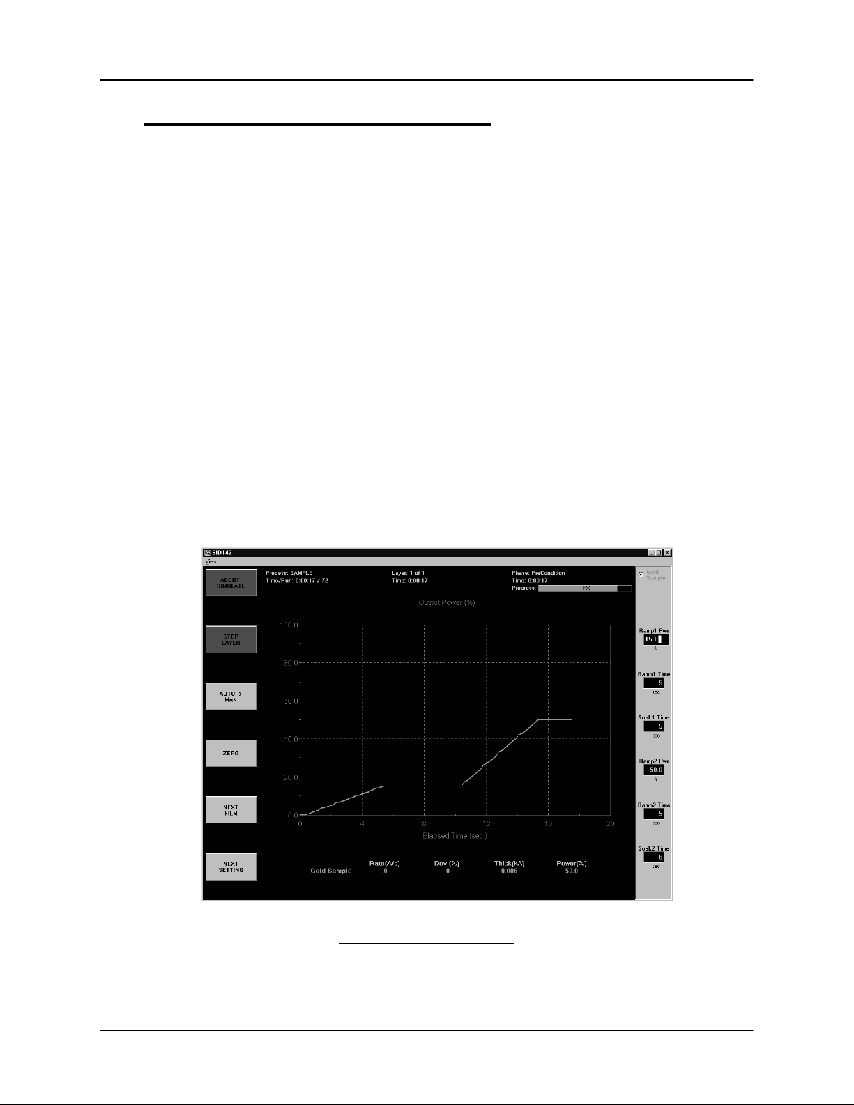
The process will start with preconditioning (i.e. Ramp1, Soak1, Ramp2, Soak2) as
shown below. Once preconditioning is complete, the process will enter the Deposit
phase. You may want to select “ABORT SIMULATE,” then “START SUMULATE”
several times to familiarize yourself with the on-screen displays during preconditioning.
You may also want to use the settings ribbon to adjust parameters while the process is
running.
Click the “View” menu and assure that these options are
selected: Film Settings, Film Readings, and Automatic. Note
that the settings “ribbon” along the right displays the preconditioning parameters you entered in the previous section.
Verify that the top SoftKey label displays “START SIMULATE.”
If “START PROCESS” is displayed, follow the instructions at
the end of Section 2.2 to enable simulate mode. Press the
“START SIMULATE” SoftKey, or click the label, to start the
process.
Preconditioning Phases
Because we selected “Automatic,” in the View menu, the graph displays Output Power
during preconditioning, then switches to Rate during the deposition phase.
2-9
Page 22
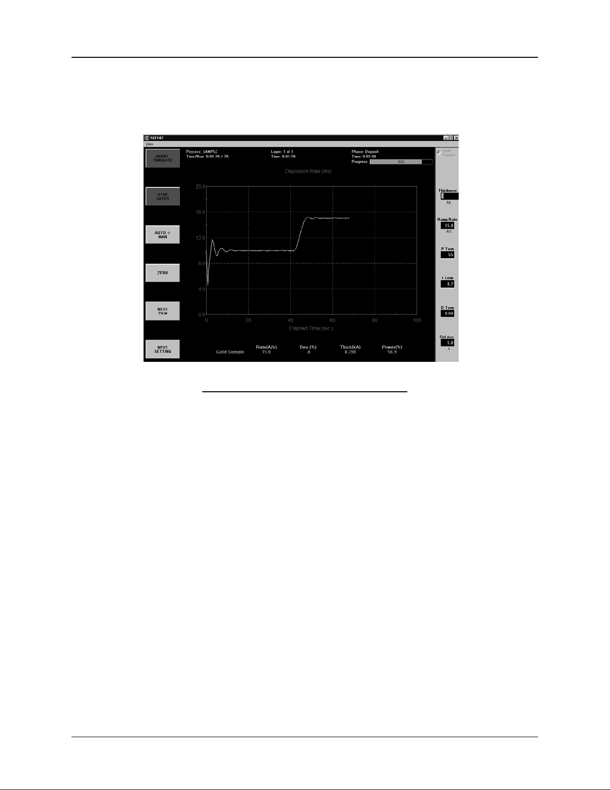
Chapter 2 Quick Start
As shown below, the initial deposition rate was 10 Å/s until a thickness of .400 kÅ.
Then the deposition rate was ramped up to 15 Å/s, and held until the desired final
thickness of 1.000 kÅ is achieved. At this point, this single-layer process is finished.
Deposition Phase with one Rate Ramp
You should adjust the PID parameters on the setting ribbon, then Start/Stop the process
several times to become familiar with their effect on control loop response.
2-10
Page 23

Chapter 2 Quick Start
2.6 SoftKey Functions
As you have seen, the SoftKey functions remain constant during deposition. Spend a
few minutes to become familiar with each of these SoftKey functions.
START
PROCESS
ABORT
PROCESS
START
LAYER
STOP
LAYER
NEXT
LAYER
AUTO->MAN
MAN->AUTO
ZERO
NEXT
FILM
NEXT
SETTING
Starts the first layer of a process when START is pushed. If
AUTO->MAN is shown on the third SofKey (AUTO Mode) the
process starts PreConditioning. If MAN->AUTO is shown on
the third Softkey (MANUAL mode) the process immediatly
starts Deposition under PID loop control.
Aborts the process. The process can only restart at the first
layer.
Starts a stopped layer, or a layer that has been designated
“Manual Start” in the process database. Starts the layer based
on the state of the AUTO->MAN SoftKey as described above.
Stops the current layer. Also changes the function of the first
SoftKey to NEXT LAYER.
Abandons the current layer and moves to the next layer in the
process. If it is the last layer of a process, the same as
pushing ABORT PROCESS.
When AUTO->MAN is pushed, the source output is set to
manual control.. You may adjust the output using the settings
ribbon. Because the PID loop is not running, you can manually
set the output power to different levels and observe the
associated deposition rate.
Returns the output to PID loop control. If the process is
running (ABORT PROCESS and STOP LAYER shown on the
first two SoftKeys) depsoition continues. If the process is
stopped, sets the output to zero and awaits a start command.
Resets the thickness reading to zero.
Sequences the setting ribbon through each Film in a
codeposition layer.
When the settings ribbon is shown, sequences the setting knob
action through each of the displayed parameters.
2-11
Page 24
Chapter 2 Quick Start
2.7 Multi-Layer CoDeposition Process
Our final example builds on the previous sections. If you have modified the setup of
your process, return to Section 2.4 and adjust the process to those values. When your
single-layer process matches Section 2.4, complete these steps:
Duplicate a
Layer
Select a
CoDep Film
Add a
CoDep Layer
Open the Edit Process dialog. Click on Layer 1, click the
“Layer” tab, then click “Copy Layer.” Now click “Paste Layer.”
A duplicate Gold Sample film will be added as Layer 2. Click
“Paste Layer” again to add a third Gold Sample layer.
Select Layer 3 in the layers list. Now select “Silver Sample” in
the films dropdown. The layers list will update to show the new
Silver Sample film assigned to Layer 3.
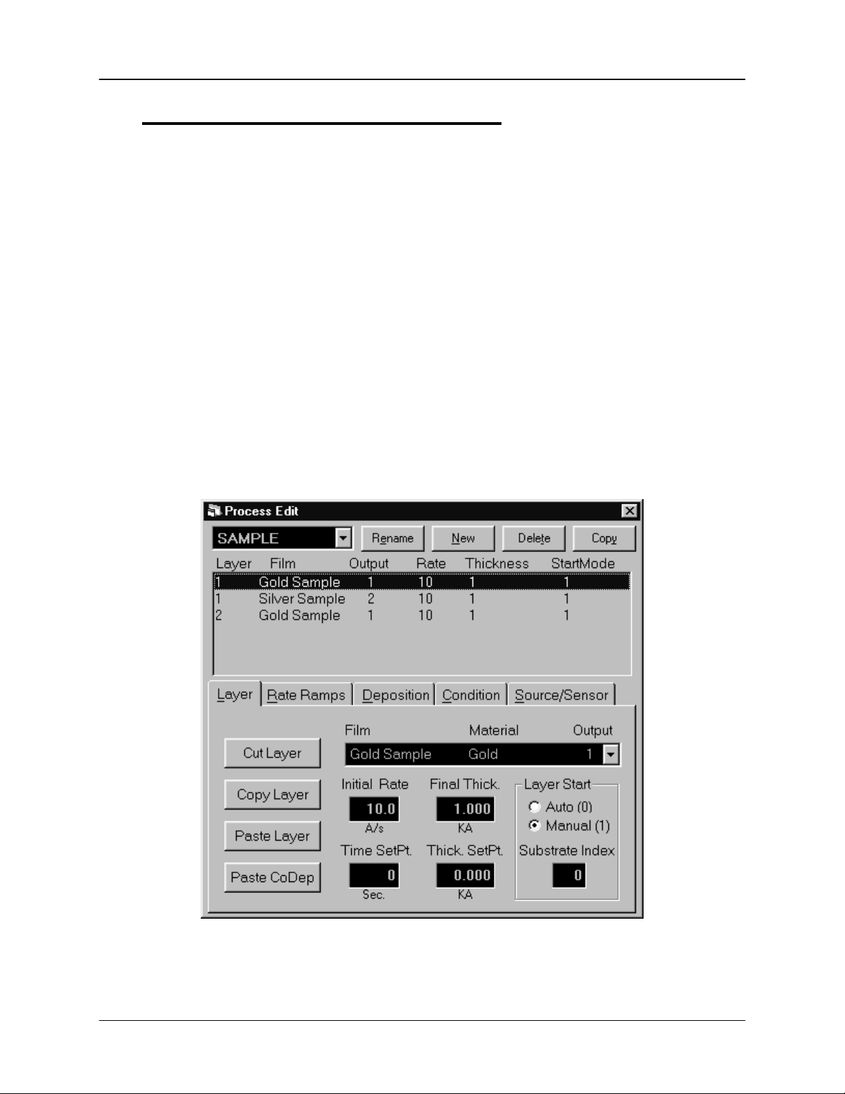
Select Layer 3 in the layers list, then click “Cut Layer.” Now
select Layer 1. Click “Paste CoDep.” The Silver Sample film
will be added below Gold Sample as a codeposition layer.
(Your setup should match the picture below.)
We now have two layers in our process. Layer 1 has Gold being deposited from source
Output 1 and Silver is being codeposited on Output 2. Layer 2 is Gold alone.
2-12
Page 25
Chapter 2 Quick Start
Hint: It’s usually best to copy a layer, then paste several temporary layers of that
type. Next, assign the films that you want to each of the pasted layers. When
selecting films for codeposition, remember that each film in a codeposited layer must
be assigned to a different source output! Now use “Cut Layer” on the temporary
layers, and “Paste CoDep” to assign the film to the desired codeposition layers.
Review this example until you are comfortable with these concepts.
Edit Layer 1
Rate & Thickness
Edit Layer 2
Rate & Thickness
Set Layers to
Auto Start
Click Silver Sample in the list of layers. Set “Initial Rate” to 15
Å/s, “Final Thickness” to 1.000 kÅ. Click the Rate Ramps tab
and adjust “Start Thickness” to 0.400 kÅ, “Ramp Time” to 15
seconds, and “New Rate” to 0 Å/s.
Click the Layer Tab, then click Layer 2. Set Final Thickness to
.5000 kÅ.
At the end of deposition, you may choose to have the next
layer wait for a Start Layer command, or to start automatically.
Select each Layer in the layers list, then click Auto to set that
layer to start automatically.
Verify that your process matches the one shown above.
Edit Silver
Deposition
Select the “Deposition” tab and the Silver Sample layer. Set
each parameter to the values shown below.
2-13
Page 26
Chapter 2 Quick Start
2-14
Page 27
Chapter 2 Quick Start
Edit Silver
Conditioning
Select the “Condition” tab and the Silver Sample layer. Set
each parameter to the values shown below.
Save Edits
Start
Process
Preconditioning of the two materials is entirely independent. If the preconditioning of
one layer takes longer than the other, the start times are adjusted so that the end times
coincide.
When preconditioning ends, codeposition of the two materials begins.
Click “Close Form” or press the first SoftKey to save this twolayer codeposition process. Answer Yes if it displays the “Do
you want to change….” message box to make this the current
process.
Press the “START SIMULATE” SoftKey to start the first layer
preconditioning phases. Note that two outputs are displayed
for this codeposition layer.
2-15
Page 28
Chapter 2 Quick Start
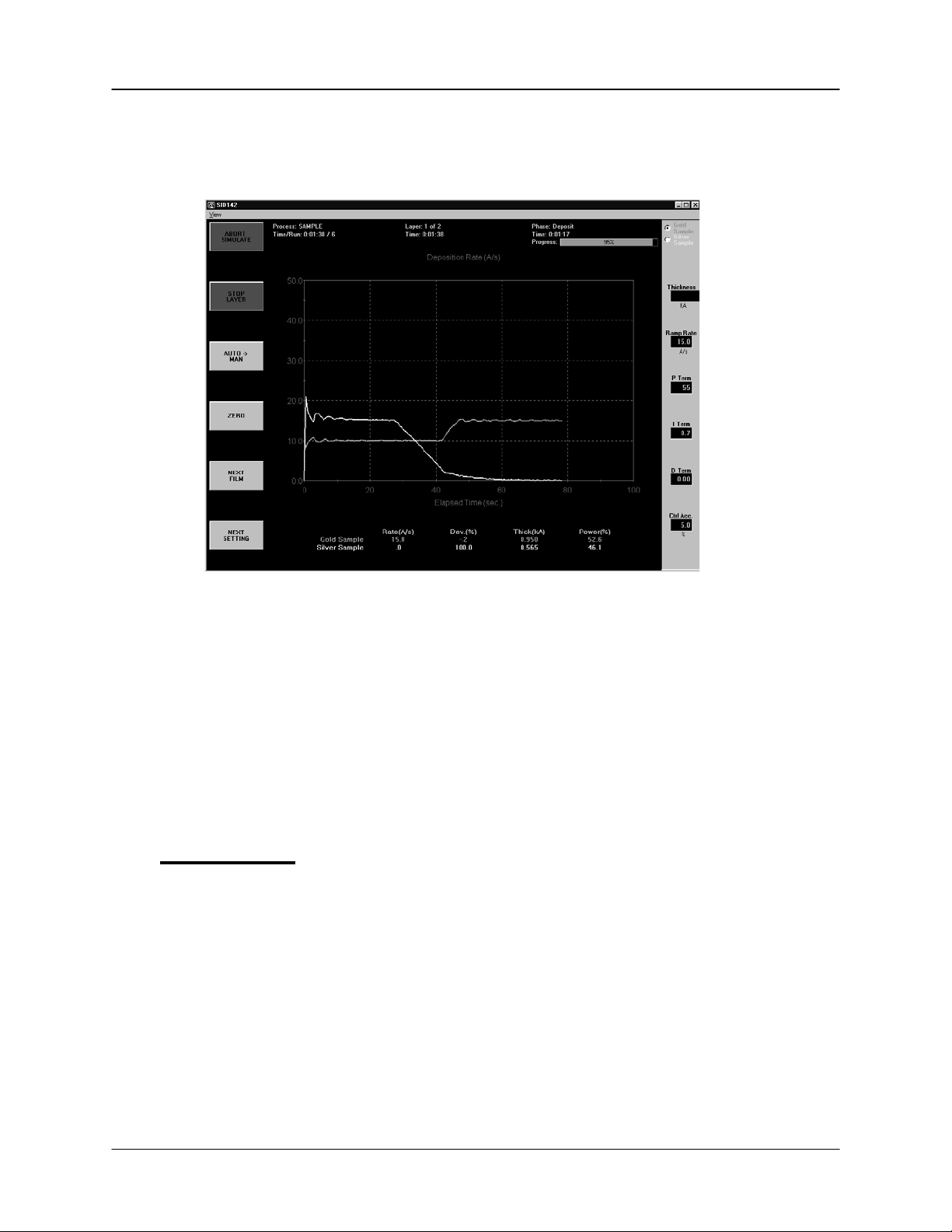
Your response should be similar to the graph shown below (your vertical scale may be
slightly different). The slight ringing on the waveforms indicates some further tuning
may be desired. However, this is an example of a reasonably well tuned loop.
At .400kÅ thickness, the Silver Sample deposition rate ramps down from 15Å/s to 0.
Similarly, at .400 kÅ thickness the Gold Sample film ramps to a higher deposition rate of
15Å/s. Because the initial rate for Gold was set lower than the initial rate for Silver,
Gold reached its .400 kÅ thickness rate ramp trigger later in the deposition cycle.
Try a P Term in the 25-30 range (less gain) for both Gold and Silver to decrease the
loop susceptibility to noise. Increasing the I Term a little, say toward 1.0, will lessen
overshoot during rate changes. The D term can be thought of as a “dead band” term.
Most systems require little or no D term.
2.8 Conclusion
Once again, spend some time with this process to become familiar with its setup, and
the effect of changes on deposition performance.
Because we selected Simulate Mode at the beginning of this Quick Start session, the
SQM-242 card is “faking” an actual process. You can use the Simulate feature at any
time to become familiar with SID-242 operation, and the effect of various settings on
process performance. It is also a very useful feature for pre-testing your process
setups. Return to the Setup menu, then select System and set the Mode to Normal to
begin running your process with the SID-242 controller.
2-16
Page 29

Chapter 2 Quick Start
This page left blank for your notes.
2-17
Page 30

Chapter 2 Quick Start
2-1
Page 31

Chapter 3 SQS-242 Software
3.0 Introduction
The SQS-242 Deposition Control Software works with Sigma Instrument’s SQM-242
Card to provide an inexpensive, yet powerful, PC based Thin Film Deposition Controller
that can:
Measure up to eight quartz crystal sensors simultaneously
Control up to four deposition source supplies simultaneously
Codeposit up to four films with preconditioning, multiple rate ramps, and
feed/idle phases
Graph deposition rate, rate deviation, or power output
Store process, film and material parameters in Microsoft Access
Use inexpensive PLCs for flexible and reliable external process controls
A typical deposition cycle for a thin film is shown below. The cycle can be broken into
three distinct phases: pre-conditioning (ramp/soak), deposition, and post-conditioning
(feed/idle). During pre-conditioning, power is supplied to prepare the source material for
deposition. When pre-conditioning ends, material deposition begins. During deposition,
the PID loop adjusts the evaporation source power as required to achieve the desired
deposition rate. When the desired thickness is reached, the evaporation source is set
to feed or idle power. At this point the process may be complete, or deposition of
another film layer may begin. If desired, up to four separate films can be codeposited
within a single layer. There is no limit to the total number of layers.
®
database
The SQS-242 software allows you to build the recipes and perform the operating
functions required to control all aspects of multi-layer thin film deposition. Process
recipes are stored in Microsoft Access format. There is no practical limit to the number
of processes, films, or materials that can be stored in the database.
3-1
Page 32

Chapter 3 SQS-242 Software
3.1 Installation and Registration
The SQS-242 install program is provided on CD-ROM. You can connect an external
USB CDROM to the SID-242 for CDROM program installation. A 3 ½" diskette install is
also possible by using another computer to copy the contents of each of the CD-ROM
“Disk” subdirectories to blank 3 ½” diskettes.
To install the program, start Windows, then insert the disk or CD-ROM into your
computer. Click Start, then Run, then type <d>:Setup (where <d> is the drive letter you
are using). Click OK to begin installation, and follow the on-screen prompts. When
installation is complete, you should restart your computer to load any new Windows DLL
and OCX support files.
The SQS-242 software can simulate deposition for demonstration and tutorial purposes.
However, an SQM-242 deposition controller card must be installed to actually read
sensors and control a source supply. The SQM-242 card can be installed before or
after the SQS-242 software. Consult the SQM-242 card User Manual for installation
information.
To start the SQS-242 program, click Start, Programs, Sigma Instruments, then SQS-
242. Until the software is registered, this Registration "nag" screen will appear.
Note: Press Cancel for full acces to the software for up to 30 runs. After 30 runs you
must contact Sigma Instruments to start the program. There is no work-around!
Press OK to show the unlock screen. In some cases your unlock "Name" may actually
be a number. If a valid Name and Unlock Code are entered, the program will start
normally. Otherwise, after three tries the program will start and decrement the
unregistered "run" counter.
3-2
Page 33

Chapter 3 SQS-242 Software
Note: If you enter a name of DEMO and Unlock Code of 5A8CAC8E5586268 the
software will be placed in Demo mode. All features of the software are permanently
available, except that readings from the SQM-242 card are only simulated. The Demo
mode can be disabled by entering a valid Name and Unlock Code later.
3.2 Operation
The SID-242 displays a progress bar during startup, then a User Login screen.
Note: The SQS-242 software ships with one pre-assigned user. The user name is
Super, with no Password. Do not confuse this with the registartion Name and Unlock
Code discussed in the previous section.
Select a User Name from the drop down box, type in the Password, and then click OK
to start the program.
If your software is configured for keyboardless operation, an on-screen keyboard will
appear as shown below. You can use your normal keyboard or mouse/touchpad to
“type” the password, then click Enter. See System Setup, SQM-242 Setup later in this
chapter to enable or disable the on-screen keyboard.
3-3
Page 34

Chapter 3 SQS-242 Software
An Access Level is associated with each User Name. The Access Level controls which
software functions are available to each user. For example, only users with an Access
Level of Supervisor can assign users. See the Security section of this chapter for
information on setting up users.
The remainder of this chapter covers the purpose and operation of each software
function, arranged by menu selections. For a more “operational” approach, consult the
previous Quick Start chapter.
Menus: The menus along the top of the main screen provide access to functions for
building deposition processes, configuring the hardware for your vacuum system, and
other less commonly used functions.
SoftKeys: The six switches to the left of the display are used for the normal operation of
the instrument, and to navigate the setup programs (see below for the individual switch
functions). Normally, you press the button that is adjacent to the labels on the SID-242
screen, but you can also use the mouse. Just move the cursor over the key label on
screen and single click the mouse. You can also use the keyboard F1 to F6 function
keys to simulate the front panel function switches. The SoftKeys change during
operation to address different user input requirements.
Setting Knob: The knob to the right of the display is used by the SID-242 to set
numeric data. A keyboard or the control’s up/down arrows can also be used.
TouchPad: On the SID-242, a touchpad is located below the setting knob. The
touchpad serves the same function as a normal mouse. Use the touchpad or mouse to
access the menus, and for functions not available from the six function keys.
3-4
Page 35

Chapter 3 SQS-242 Software
3.3 File Menu
Note: The current process must be stopped for the File menu to be available.
Process: Used to select a process from a list of all processes in the database. If the
process selected is different than the current process, you are prompted to confirm the
change.
Open Database: Selects a process database to be used for deposition. Remember, a
single process database may contain an unlimited number of processes, films, and
materials.
Save Database As: Saves the current process database to disk under a different name.
This is useful for saving the process database to floppy disk (for backup!), or for making
trial changes without affecting your working database.
Once again, a pop-up keyboard may appear. If you want to browse or type in the
database name, just select Cancel from the pop-up keyboard. Process databases are
saved in Microsoft Access format.
Data Logging: Saves deposition data to a .LOG text file. If an option other than “None”
is selected in the Log File section, data logging is activated. When the Start SoftKey is
pushed, process data is saved in a .LOG file in the SQS-242 installation directory
(typically: \Program Files\Sigma Instruments\SQS-242).
There are three options for file naming and logging. If “Overwrite” is selected, only the
last run of the process is saved as ProcessName.LOG. Subsequent runs overwrite the
log file. If “Append” is selected, each run is appended to ProcessName.LOG. If “Run#”
is selected, each run of the process is saved as a separate file under the format
ProcessName_Run#.LOG.
3-5
Page 36

Chapter 3 SQS-242 Software
A number of “events” can trigger a data entry in the log file. “End Deposit Phase”
records process data (rate, thickness, time, etc.) at the end of each layer’s deposit
phase. Similarly, “End Each Phase” logs data at the end of each phase (conditioning,
depositing, etc.). “I/O Events” logs data each time an external digital input or output
changes. Finally, “Timed Logging” records data at the selected time intervals
throughout the process.
There are two formats for writing data. If “Spreadsheet” is selected, each entry is a
comma-delimited line of data. If “Text” is selected, the data is formatted for easy
reading. The first few lines of the LOG file is a heading that illustrates the file format
and content. Log files can be viewed using a word processor or spreadsheet program.
Print Process: Prints the parameters for the current process to the system printer.
Select “Print to File” in the Printer Setup Menu to print the data to a file.
Print Setup: Selects and modifies the current system printer.
User Login: Displays the User Login screen so that a different user may log in. The
existing user is logged off automatically. The user Access Level changes immediately
to that of the new user.
Exit: Exits the SQS-242 deposition control program.
3-6
Page 37

Chapter 3 SQS-242 Software
3.4 Edit Menu
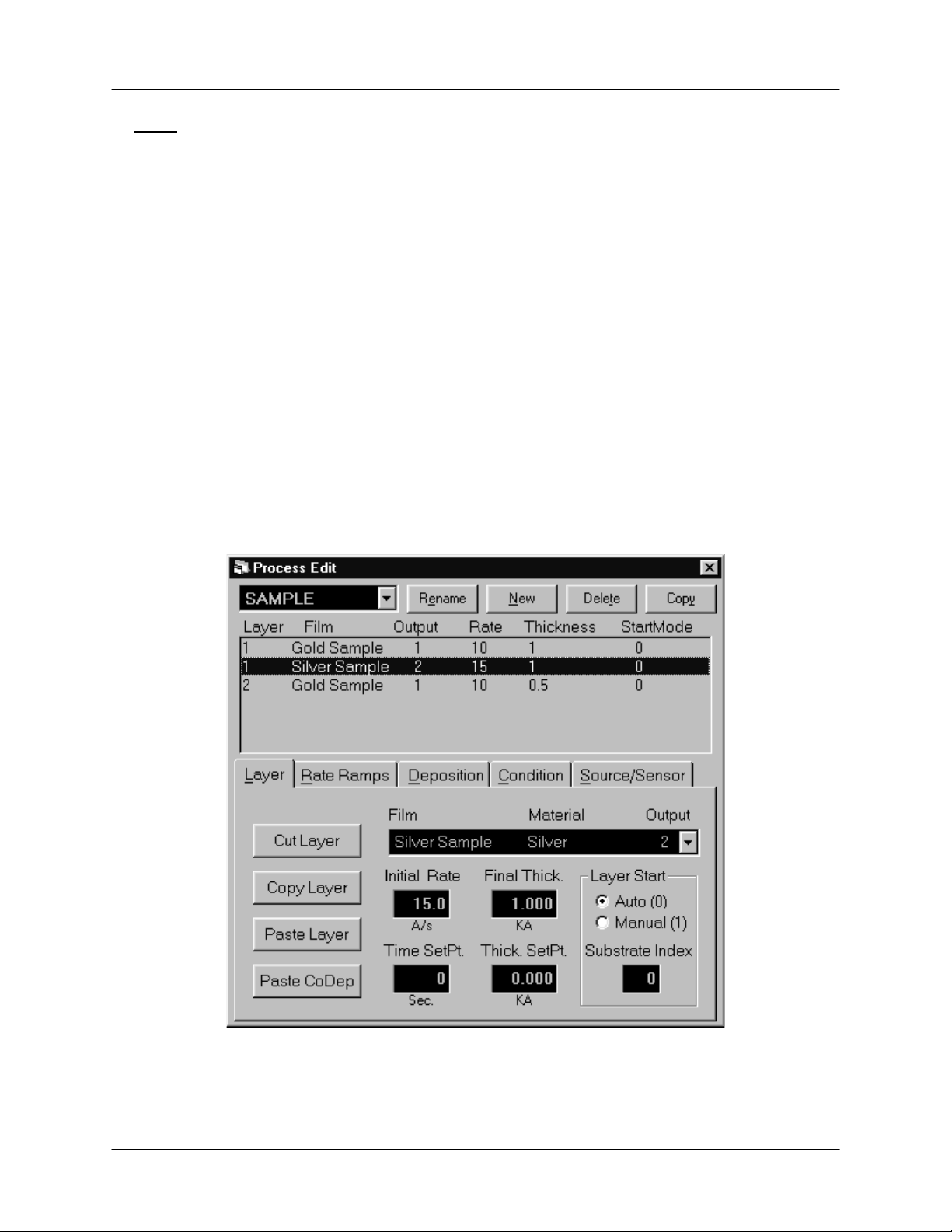
3.4.1 Edit: Process
A process is a sequence of film layers. Multiple films deposited in the same layer are
known as codeposition. A listing of each film in the selected process appears in the
layers list box. Films in codeposition layers are listed with the same layer number, but a
different output. Select a layer to edit its parameters in the tabbed dialog boxes.
The Edit Process dialog provides all the functions needed to develop a thin film
deposition process from the database of existing films and materials. The Layer and
Rate Ramp tabs specify the sequence of films to be deposited. The Deposition,
Condition, and Source/Sensor tabs provide control over the individual films assigned to
each layer.
Note: Edits to the Deposition, Condition, and Source/Sensor tabs will affect all
processes and layers that use the selected film!
Process: A drop down box that selects the process to be edited. Defaults to the current
process.
Rename: Edits the name of the selected process.
New: Creates a new process. Since every process must have at least one film, the first
film of the currently selected process is used.
Delete: Deletes the currently selected process from the database. There is no
undelete!
Copy: Creates a duplicate of the currently selected process.
3-7
Page 38

Chapter 3 SQS-242 Software
Layer Tab
The layer tab provides the capabilities needed to add and delete process layers, as well
as to edit the film, rate & thickness for each layer. Normally each film in a process is
run sequentially, as layers. Codeposition represents different films that are deposited
concurrently with other films, in the same layer.
Cut Layer: Removes the layer selected in the Layers list box from the process, and
places the layer on the clipboard.
Copy Layer: Places the layer selected in the Layers list box on the clipboard, without
removing it from the process.
Paste Layer: Inserts the clipboard layer above the currently selected layer in the Layers
list box. Existing layers are shifted down.
Paste CoDep: Pastes the clipboard layer as a codeposition layer at the currently
selected layer number. Films that use outputs already assigned to the selected layer
are invalid.
3-8
Page 39

Chapter 3 SQS-242 Software
Hint: To add layers to a process, it is easiest to click an existing layer in the layers
list then click Copy. Click Paste to insert several temporary layers of that type. Next,
assign the proper film to each of the layers, using the Film dropdown box.
When selecting a Film for a codeposition layer, remember that each film must be
assigned to a different source output! To change an existing layer to a CoDep layer,
highlight the existing layer and click “Cut Layer.” Next click the layer desired for
CoDep and click “Paste CoDep” to assign the selected layer. The Multi-Layer
CoDeposition Process section of Chapter 2 illustrates this concept.
Film: Selects the film that is assigned to the selected layer. Changing a layer’s film also
changes the film related parameters for that layer (i.e. preconditioning, PID, material,
etc.)
Initial Rate: Sets the initial deposition rate setpoint for the selected layer. If no rate
ramps are defined for the layer, this is the rate setpoint for the entire layer.
Final Thickness: Sets the endpoint thickness for the selected layer. When final
thickness is reached, deposition is stopped for that layer and the feed/hold phase is
entered.
Time Setpoint: Sets an arbitrary time, after deposition begins, when the time setpoint
relay is activated.
Thickness Limit: Sets an arbitrary thickness when the thickness limit relay is activated.
Auto/Manual Start: Determines whether a layer begins automatically upon completion
of the previous layer. If Manual Start is selected, the previous layer ends at its idle
power and waits for the user to push the Start Layer switch.
Substrate Index: If using a substrate indexer, assigns the substrate to a specific angle
or placement value (0-15). These values are sent to the digital I/O PLC at the beginning
of each layer for interfacing to a specific indexer. See System Setup and Digital I/O for
other settings that pertain to the substrate index.
3-9
Page 40

Chapter 3 SQS-242 Software
Rate Ramps Tab
Rate ramps cause changes to the deposition rate over time under PID control. Each
rate ramp has a starting thickness, an elapsed time to ramp to the new rate, and a new
rate setpoint. Each process layer can have an unlimited number of rate ramps.
Insert Ramp: Inserts a new rate ramp for the selected layer, at the selected position in
the rate ramps list. Existing rate ramps are shifted down.
Delete Ramp: Deletes the selected rate ramp.
Move Up: Shifts the selected rate ramp up one position.
Move Down: Shifts the selected rate ramp down one position.
Start Thickness: The thickness that triggers a timed ramp to a new rate. (Start
thickness should be greater for each subsequent ramp, and less than the final layer
thickness, otherwise the rate ramp is skipped.)
Ramp Time: The time (in seconds) to ramp to the new rate. If the rate ramp is too fast,
a PID control error may be generated.
New Rate: The new deposition rate setpoint for the selected layer.
3-10
Page 41

Chapter 3 SQS-242 Software
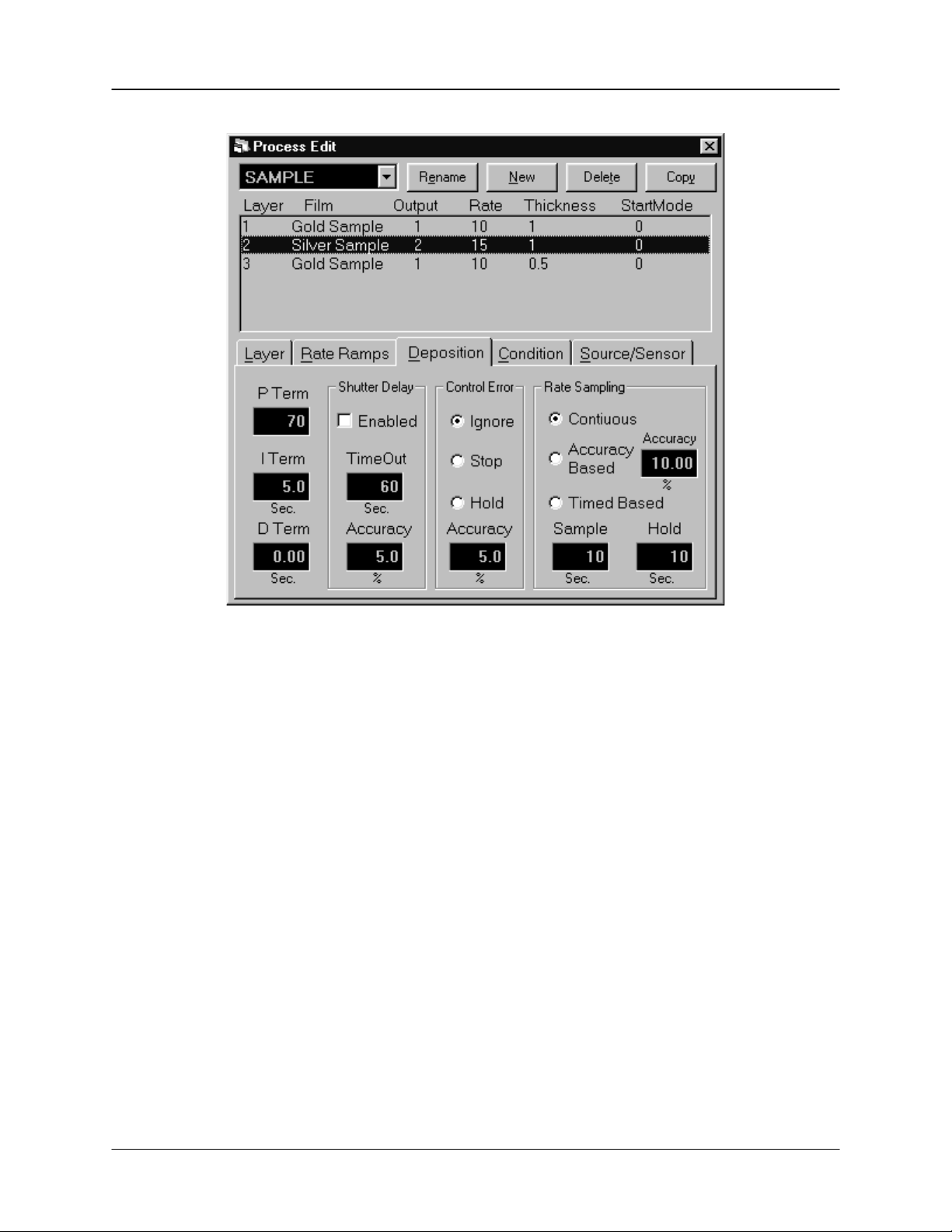
Deposition Tab
The deposition tab contains parameters that directly affect the deposition phase of the
process cycle.
P Term: Sets the gain of the control loop. High gains yield more responsive (but
potentially unstable) loops. Try a value of 50, then gradually increase/decrease the
value to respond to step changes in rate setpoint.
I Term: The integral term controls the time constant of the loop response. A small I
term, say .5 to 1 seconds, will smooth the response of most loops.
D Term: The differential term causes the loop to respond quickly to changes. Use 0 or
a very small value to avoid oscillations.
3-11
Page 42

Chapter 3 SQS-242 Software
Shutter Delay: It is often desirable to assure stable process control before the substrate
shutter opens. Enabling shutter delay requires that the system reach the programmed
control accuracy, and maintain that accuracy for 5 seconds, before deposition begins. If
the programmed accuracy is not reached, the process halts. If accuracy is reached, the
substrate shutter opens and deposition begins once the accuracy has been maintained
for 5 seconds. The Thickness reading is zeroed at the end of the shutter delay period.
The time out function sets the length of time the system will wait for control before
aborting.
Control Error: If the control loop cannot maintain the desired deposition rate, due to
loss of source material, excess rate ramps, or equipment malfunction, a control error
occurs. The error condition can be ignored, the process stopped (output power to 0%),
or the output power held at the same level as when the error occurred. If hold is
selected, PID control is abandoned, but the process will continue to be monitored for
thickness setpoint. The control error accuracy is the value that must be exceeded for 5
seconds to trigger a control error. Use shutter delay accuracy to assure adequate
process control before entering the deposition phase.
Rate Sampling: Rate sampling can extend the life of crystals. With rate sampling, the
deposition rate is sampled for a period of time, then the sensor shutter is closed. Power
is then held at the same level as the final power setting during the sample period.
Continuous selects no sampling; the sensor shutter remains open during deposition.
Accuracy Based sampling opens and closes the shutter at the rate required to maintain
the desired accuracy during the hold phase. Time Based sampling opens the shutter
for a fixed period of time then closes it for a fixed time.
3-12
Page 43

Chapter 3 SQS-242 Software
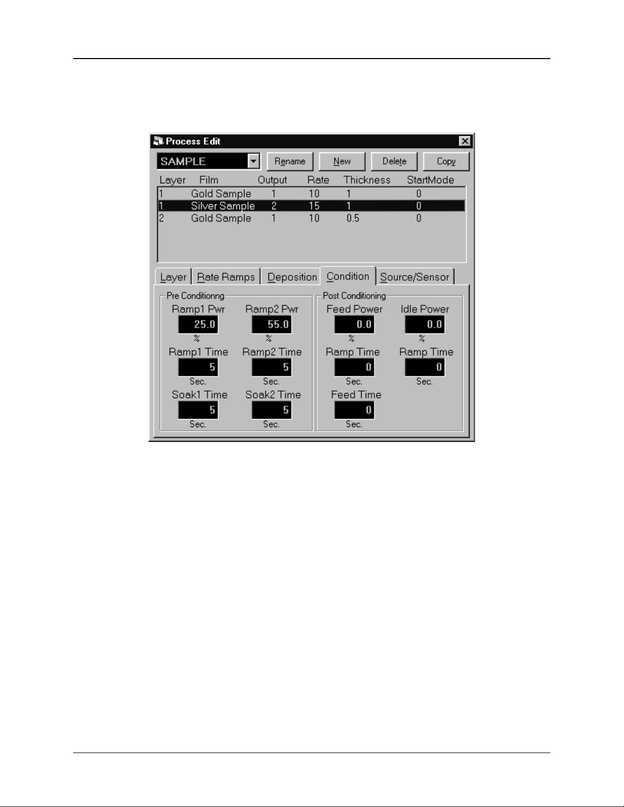
Condition Tab
Before deposition begins, it is often necessary to precondition the source material.
This places the system at the proper power level to achieve rapid PID control when
deposition begins.
Ramp 1: Ramp power sets the power level that is desired at the end of the ramp phase,
in % of full scale. Ramp time sets the time to ramp with a linear rate from the initial
power to the Ramp power. Soak time sets the time the output remains at the ramp
power level.
Ramp 2: Ramp 2 functions are the same as Ramp 1. Typically, Ramp 2 power is set
near the power level required to match the desired initial deposition rate.
Feed: The feed phase holds output power at the level and time required to wire feed
new material.
Idle: The Idle phase ramps the material to a state that is ready for deposition, typically
the same as Ramp 2 power.
3-13
Page 44

Chapter 3 SQS-242 Software
Source/Sensor Tab
The Source/Sensor tab controls the physical setup of the deposition system.
Material: Selects the physical deposition material
Max Power: The maximum output power allowed for the selected output. The full scale
output voltage is a function of the deposition power supply input specifications, and is
set in the SQM-242 setup. Max Power controls the maximum % of the full scale power
that can be used by this process layer.
Slew Rate: The maximum power change allowed on an output, per second. If rate
ramps or PID power requirements exceed this value, an error will occur.
Source Index: If using a source index, assigns each film to a specific pocket (one of 16
values). These values are sent to the PLC at the beginning of each layer. See the
System Setup for other settings that pertain to the source index.
Output: Assigns the selected material to one of the source control outputs. When an
output is selected, the Sensor Tooling panel changes to show only those sensors that
are assigned to that output in the Edit, System dialog. The combination of a source
output and its sensor inputs defines the deposition “control loop” for the selected
material.
3-14
Page 45

Chapter 3 SQS-242 Software
In codeposition, a layer may have multiple films, with each material using a different
output and sensor(s) for control. However, no layer can have the same output assigned
to more than one film. If you try to assign the same output to multiple films in a layer, an
error message will be displayed. Reassigning a film to a different output to eliminate
this error may impact other stored processes. If the change would create an output
conflict in another process, an error message is displayed.
Sensor Tooling: Adjusts for sensor measured deposition rates that differ from the
substrate deposition rate. A higher tooling value yields higher rates. For example, if the
sensor sees only 50% of the substrate rate, set the value to 200%. Setting Tooling to
0% causes a sensor to be ignored for this film.
3-15
Page 46

Chapter 3 SQS-242 Software
3.4.2 Edit: Films
The Edit Films dialog provides a subset of the functions of the Edit Processes dialog.
The functions are those that pertain only to a specific film.
NOTE: Edits to a Film will affect all processes and layers that use that film!
Film: A drop down box that selects the film parameters displayed in the edit film dialog
box. Defaults to the current process film.
Rename: Edits the name of the selected film.
New: Creates a new film.
Delete: Deletes the currently selected film from the database. A film cannot be deleted
if it is used in ANY database process!
Copy: Creates a duplicate of the currently selected film.
The function of each Edit Films tab, and its associated controls, are identical to those
detailed in the Edit Processes section. Please consult 3.4.1 for that information.
3-16
Page 47

Chapter 3 SQS-242 Software
3.4.3 Edit: Materials
The Edit Material dialog provides the functions needed to build a materials database. In
addition to the functions listed below, the main screen function keys provide capabilities
to add/edit/delete materials.
Material: Selects a material to edit.
Density: Sets the density for this material. Material density has a significant impact on
deposition calculations.
Z-Factor: Sets the Z-factor, an empirically determined measure of a material’s effect on
quartz crystal frequency change. Z factor has no effect on measurements when using a
new crystal. If the Z Factor for your material is not known, using crystals with >80% life
will eliminate the Z Factor term.
See the Appendix for a list of standard Material Parameters (Density and Z-Factor).
3-17
Page 48

Chapter 3 SQS-242 Software
3.4.4 Edit: System
Sets the operation of system Sensors, Sources, Digital I/O, and SQM-242 measurement
card(s).
Sensors Tab
Sensor Name: A meaningful name assigned to sensors 1 to 4 in single card systems; 1
to 8 in two card systems. For clear display, keep the name to less than 8 characters.
Sensor Output: The source output that a sensor is positioned to measure. Typically
each sensor measures deposition from a particular source. If multiple sensors are
assigned to a single output, the sensor readings are averaged when calculating rate
and thickness. Setting a sensor’s Tooling to 0% in Film setup can override this
assignment and disable a sensor - see the Sensor Tooling section.
Sensor Dual: Indicates that a pair of sensors is setup as primary/secondary duals.
When the primary sensor fails, the SQS-242 switches to the secondary sensor.
Max/Min/Initial Frequency: The frequency values for the quartz crystal sensors used
as inputs to the SQM-242. Sensor readings outside the min/max values cause an error.
Completion Timer: If Complete Signal is checked, the process will halt if a move
complete signal is not received within this timeout period. If Complete Signal is not
checked, the process waits for this fixed time period before starting a layer.
Complete Signal: Check this box if your substrate index sends a signal designating
that the move is complete and preconditioning can begin.
3-18
Page 49

Chapter 3 SQS-242 Software
Sources Tab
Output Name: A meaningful name assigned to SQM-242 outputs 1 and 2 in single card
systems; 1 to 4 in two card systems. For clear display, keep the name to less than 8
characters.
Full Scale: The input voltage required by the deposition source power supply to
produce 100% output power. Positive or negative full scale values are possible.
Completion Timer: If Complete Signal is checked, the process will halt if a move
complete signal is not received within this timeout period. If Complete Signal is not
checked, the process waits for this fixed time period before starting a layer.
Complete Signal: Check this box if your source index sends a signal designating that
the move is complete and preconditioning can begin.
Test Output: Useful for testing source wiring and Full Scale voltage settings. Select an
output, then click Send to set the SQM-242 card output to its Full Scale voltage. Click
Clear to return the selected output to 0 volts.
3-19
Page 50

Chapter 3 SQS-242 Software
Digital IO Tab
The SID-242 uses an inexpensive PLC to provide digital I/O capabilities. The Digital I/O
tab assigns deposition events (i.e. open shutter, start deposit, final thickness, etc.) to
the available relays and inputs on the PLC.
Note: Omron CPM series PLCs number relays from 10.00 to 10.07, then 11.00 to
11.07. These correspond to Relays 1 to 16 on the Digital I/O tab. Similarly, inputs 0.00
to 0.11 on the Omron PLC correspond to inputs 1 to 12 on this screen.
Relay Events: The relay events dropdown box lists the deposition events that can
cause a relay output to be activated. To assign a deposition event to a relay, click the
Relay #, then select the desired event from the dropdown box. As you click each
Relay#, the dropdown will change to show its currently assigned event. A description of
each relay (output) event follows:
Source Shutter 1 and 2 (and 3-4 for a Dual Card System)
These 2 relays are used to control the Shutter that covers your deposition source.
When you enter the deposit phase, the appropriate relay will close its contacts, which
causes the shutter to swing out of the way. When the deposit phase finishes the shutter
relay contacts open.
Sensor Relays 1 through 4 (and 5-8 for a Dual Card System)
These 4 relays are used to control sensor shutters. Their function depends on whether
you have single or dual sensors.
3-20
Page 51

Chapter 3 SQS-242 Software
If Dual Sensor is not selected (i.e. a single sensor), the relay contacts are closed when
you are in a layer with the sensor enabled. As an example, let’s say you have sensors
1 and 3 enabled for Film 1 and sensors 2 and 4 enabled for Film 2. When you start Film
1, the contacts for Sensor Relays 1 and 3 will close. When you start Film 2, these
contacts open and the contacts for Sensor Relays 2 and 4 will close.
If you have the SQS-242 software configured for dual sensors, the operation of these
relays is considerably different. Dual sensors use either Sensor Inputs 1 and 2, or
Inputs 3 and 4. In this case, only Sensor Shutter Relays 1 and 3 have meaning, Relays
2 and 4 are always open. With the relay contacts open, Sensors 1 and 3 are selected.
If a Crystal Fail is detected during the running of a film, the Sensor Shutter Relay’s
contacts will close for the duration of that film. This selects the second sensor in the
Dual Sensor assembly for the remainder of the film.
Xtal All Good and Xtal All Fail Relays
These two relays provide an indication of the general health of your sensors. If the Xtal
All Good Relay is closed, then all enabled sensors are returning a valid reading. If the
Xtal All Fail Relay is closed, none of the enabled sensors are returning a valid reading.
Process Stopped and Running Relays
These relays indicate the overall status of the process. The Process Running relay
closes as soon as Start Process is selected (by front panel or digital input), and opens
when Abort Process is selected. Even if a layer is stopped within a process, the
Process Running relay remains closed until the last film of a process has finished. The
Process Stopped relay contacts behave in the inverse manner.
Process Active
This relay action is similar to the Process Running relay, except it will open if the
process is temporarily halted for any reason, e.g. a Manual Start layer.
Layer Stopped and Running Relays
The Layer Running relay closes as soon as Start Layer is selected (by front panel or
digital input), and opens when Stop Process is selected. The Layer Stopped relay
contacts behave in the inverse manner.
Deposit Phase Relay
This relay indicates that you are in the deposit phase of a film. It is like having the two
Source Shutter Relays connected in parallel. If you have shutter delay enabled, this
relay will wait until the end of the shutter delay before going active.
Pre-Cond Phase Relay
This relay closes for the preconditioning phases (Ramp1, Soak1, Ramp2, Soak2) of a
film.
3-21
Page 52

Chapter 3 SQS-242 Software
Soak Hold Phase Relay
This relay closes for the Soak and Hold phases after deposition.
Manual Mode Relay
Closes when the program is placed in Manual mode.
Max Power Relay
Closes when any control voltage output is at the programmed maximum power level.
Thickness Setpoint Relay
This relay will become active when the Thickness Setpoint is reached. This is a
programmable process parameter.
Time Setpoint Relay
This relay will become active when the Time Setpoint has been reached. This is
measured from the beginning of the deposit phase, and is a programmable parameter.
Input Events: The input events dropdown box lists the deposition events that can be
caused by an external digital input. To assign a deposition event to an input, click the
Input #, then select the desired event from the dropdown box. As you click each Input#,
the dropdown will change to show its currently assigned event. A brief description of
each input event follows:
Start Process Input
Triggering this input is the same as pushing the Start Process button.
Abort Process Input
Triggering this input will abort the process.
Start Layer Input
Triggering this input will start or restart the current layer.
Stop Layer Input
Triggering this input will stop the current layer.
Start Next Layer Input
Triggering this input will skip the current layer and start the next layer.
Zero Thickness Input
This will zero the thickness. It is identical to pressing the Zero Button.
Force Final Thickness Input
Triggering this input has the same as effect reaching Final Thickness setpoint.
3-22
Page 53

Chapter 3 SQS-242 Software
PLC Tab
Comm Port: Selects the serial port used to communicate with the PLC. The Comm
Port drop down lists the available ports. However, some of the ports may be used by
other devices (modem, mouse, etc.). Select Disabled to prevent I/O from using the
PLC.
Address: Several PLCs can be controlled from a single computer Comm Port by
connecting their expansion ports. The slave address of each such PLC is usually set by
a rotary or dip switch, and must be unique. Single PLC systems usually use Address 0.
Consult your PLC User Manual.
Test: The Test section provides a simple means of testing your PLC communications
and digital I/O wiring. To set a relay on the PLC, go to the Digital I/O tab and find which
I/O event is assigned to that relay. On the PLC tab, select the same event in the Test
Relay dropdown, then click Set. The assigned Relay# should close. Click Clear to
open the relay. Use the Source and Substrate Move sections to test indexers.
To test a digital input, find the Input# that is assigned to an event on the PLC tab.
Select the input event in the dropdown, then click Read Input to verify the state of the
PLC input.
Registers: The PLC used for I/O runs a small monitor program that transfers relay and
input states from the PLC connecting block to internal registers. The SQS-242 software
reads/writes to those registers though the PLC’s Comm port. The registers shown are
those that have been programmed for your PLC. Because their redefinition is not a
trivial task, these values cannot be changed in the SQS-242 program. Contact Sigma
Instruments if you need to change the internal PLC register definitions.
3-23
Page 54

Chapter 3 SQS-242 Software
SQM-242 Tab
Normal/Simulate: In Normal mode, the SQS-242 gets readings from the SQM-242
card(s). In Simulate mode, the SQS-242 generates simulated readings even if a card is
not installed. Useful for testing new processes and learning the software.
Note: In Simulate Mode, a deposition rate is not “measured” until the output power
exceeds 50%.
Period: Sets the measurement period between .2 seconds (5 readings per second) and
2 seconds. A longer period gives higher reading accuracy, especially at low rates.
Filter: Sets the number of readings used in the reading filter. A low setting gives rapid
response to process changes, high settings give smoother graphs.
Address: Sets the address of the SQM-242 ISA card in the computer’s address space.
See the SQM-242 Chapter of this manual for detailed setup instructions.
Interrupt: Sets the interrupt used by the SQM-242 ISA card. See the SQM-242
Chapter of this manual for detailed setup instructions.
Slave Enabled: When a second SQM-242 card is present, it enables/disables sensors
5-8 and outputs 3 and 4.
Front Panel Enabled: When used with the SRC series computer, enables/disables the
SQS-242 software to read the SoftKeys and setting knob.
SQM-242 Revision: Firmware revision of the SQM-242 card.
3-24
Page 55

Chapter 3 SQS-242 Software
Comm Tab
RS-232 Port: Selects the comm port used for serial communications with another
computer. This is NOT the same port used by the PLC for I/O. The Comm Port drop
down lists available ports. However, some of the ports may be used by other devices
(PLC, modem, mouse, etc.).
Baud Rate: Sets the baud rate used for serial communications.
Ethernet Port: Sets the TCP/IP port used by the SQS-242 software for Ethernet
communications, 1001 is a typical value.
Ethernet Name: Sets the name of the external computer the software will be
communicating with. The name is either an IP address (xxx.xxx.xxx.xxx) or the Name
assigned in the Windows Network setup. It is NOT the name or IP address of the
computer the SQS-242 software is installed on.
Receive Data: Displays the Query and Update requests received from the Comm and
Ethernet port. See Appendix B for a description of the serial communications protocol.
Transmit Data: Displays the response to Query and Update requests received from the
Comm and Ethernet port.
Note: The Monitor section does not show communications with the PLC.
3-25
Page 56

Chapter 3 SQS-242 Software
3.4.5 Edit: Security
The Security menu assigns Users, their Password, and their Access Level. It also
provides a flexible way to assign program functions to different Access Levels.
Note: The Security dialog is available only to users with Supervisor Access.
Users Tab
User: Drop down used to select an existing user, to edit their Access or Password. It is
not possible to edit or add a user name in the User drop down. Use the New SoftKey to
create a new User. Use the Delete SoftKey to delete the selected user.
Access: Assigns a program access level to the selected user. Generally speaking,
Supervisor (SUPV) provides access to all program functions. Technicians (TECH) have
access to a subset of functions. While User level access (USER) has access to only
those functions needed to run deposition processes. See the Access Tab section to
assign SUPV, TECH, and USER program capabilities.
Password: Each user will typically have their own password. When a password is
entered, a second box will appear for password confirmation. If the Password box is left
blank, no Password is needed for that user to login.
3-26
Page 57

Chapter 3 SQS-242 Software
Access Tab
The Access tab allows Supervisors to assign which menu selections are available to
each of the three Access Levels. When a program menu is assigned to a particular
access level, it is automatically available to higher access levels.
In the example below, every user has access to the File Process menu and the File Exit
menu. Only Supervisors have access to the Edit System and Edit Security menus. The
remaining menus are assigned TECH access. They will be available to TECH and
SUPV users, but not to USER access users.
Those who login with USER access can select and run processes, but they cannot edit
process parameters. TECH’s can also select and run processes (because those
functions are assigned to a lower level access). However, TECH’s can also edit
process parameters. Only Supervisors can change System Setup or Security
assignments.
3-27
Page 58

Chapter 3 SQS-242 Software
3.5 View Menu
The view menu controls the appearance of the main display.
Film Settings: Displays/hides a ribbon of commonly accessed process settings along
the right of the screen. Additional process parameters are available in the Edit menu.
When displayed, the settings ribbon allows the user to easily modify process settings
during deposition without leaving the main screen. Changes are made to the current
process and the process database immediately. In codeposition, first click on the
desired film to display its parameters.
Film Readings: Displays/hides film deposition readings along the bottom of the screen.
Readouts of Film, Rate, Deviation, Thickness, and Power are displayed simultaneously
for each of the active outputs. The rate, deviation, and thickness readings displayed
represent an average of the quartz sensors assigned to each film.
Sensor Readings: Displays/hides a pop up window of sensor rate, thickness,
remaining life, and frequency readings. Unlike the main screen’s Film Readings, this
display is the raw data coming from each sensor. In addition, the output (i.e. PID
control loop) that each sensor is assigned to is displayed. Sensor assignments are
established in the SQM-242 Setup menu.
Rate Graph: Fixes the main graph to deposition rate. Deposition rate is useful during
the shutter delay, rate ramp, and deposition phases. During other phases, the power
output graph is usually more useful.
Deviation Graph: Fixes the main graph to display percent deviation from the rate
setpoint. Rate deviation is useful for fine tuning the PID control loop.
Power Graph: Fixes the main graph at output power. Output power is directly adjusted
during the preconditioning, feed, and hold phases. Output power is also useful during
the deposition phases to detect error conditions, which cause oscillations. Be sure the
Full Scale voltage is set properly in the SQM-242 Setup menu.
Automatic: Changes the main graph to display the most pertinent information for each
deposition phase. During preconditioning, output power is displayed. During shutter
delay, rate ramps, and deposition, the main graph displays deposition rate. During feed
and hold phases, the graph reverts to output power.
3-28
Page 59

Chapter 3 SQS-242 Software
3.6 Software Specifications
Display
Graphs ................................................................................. Rate, Deviation, Power
Readouts .............................................................................. Rate,Dev,Thick,Power
Process Parameters
Name .................................................................................... 12 characters
# Processes ......................................................................... Unlimited
# Layers ............................................................................... Unlimited
# Sensors (Dual) .................................................................. 1 to 8 (4 Dual)
# Sources ............................................................................. 1 to 4
Layer Parameters
Start Mode ............................................................................ Auto/Manual
Rate ...................................................................................... 0.0 to 999.9 /sec.
Thickness ............................................................................. 0.0 to 999.9
Thickness Limit .................................................................... 0.0 to 999.9
Time Setpoint ....................................................................... 0 to 30000 sec.
# Rate Ramps ...................................................................... Unlimited
Rate Ramp Start................................................................... 0.0 to 999.9
Rate Ramp Time .................................................................. 0 to 1000 sec.
New Rate ............................................................................. 0.0 to 999.9 /sec.
Substrate Index .................................................................... 0 to 15
Film Parameters
Name .................................................................................... 12 characters
Ramp Time (1,2) .................................................................. 0 to 30000 sec.
Soak Power (1,2) ................................................................. 0.0 to 100.0 %
Soak Time (1,2) .................................................................... 0 to 30000 sec.
Shutter Delay Time ............................................................... 0 to 200 sec.
Shutter Delay Error ............................................................... 0.0 to 30.0 %
P Term ................................................................................. 1 to 9999
I Term ................................................................................... 0 to 99.9 sec.
D Term ................................................................................. 0 to 99.9 sec.
Control Error ......................................................................... Ignore/Stop/Hold
Control Error Set .................................................................. 0 to 30.0 %
Feed Ramp Time.................................................................. 0 to 30000 sec.
Feed Power .......................................................................... 0.0 to 100.0 %
Feed Time ............................................................................ 0 to 30000 sec.
Idle Ramp Time .................................................................... 0 to 30000 sec.
Idle Power ............................................................................ 0.0 to 100.0 %
Tooling (Sensor 1 to 8) ......................................................... 10.0 to 999.0
Max Power ........................................................................... 0.0 to 100.0 %
Slew Rate ............................................................................. 0.0 to 100.0 %/sec.
Source Index (Pocket) .......................................................... 0 to 15
3-29
Page 60

Chapter 3 SQS-242 Software
Material Parameters
Name .................................................................................... 12 characters
Density ................................................................................. .0.40 to 99.99 gm/cm
Z-Factor ................................................................................ 0.100 to 9.900
Computer Interface
Type ..................................................................................... RS-232
Protocol ................................................................................ Text string with checksum
Digital Inputs (available only with PLC option)
Start Process ........................................................................
Stop Process ........................................................................
Start Layer ............................................................................
Stop Layer ............................................................................
Start Next Layer ...................................................................
Zero Thickness .....................................................................
Force Final Thickness .........................................................
Substrate Index Complete
Source Index Complete
Relay Outputs (available only with PLC option)
Source Shutter ..................................................................... 1 to 4
Sensor Shutter ..................................................................... 1 to 8
All Crystal Fail ......................................................................
All Crystal Good ...................................................................
Process Running ..................................................................
Process Stopped ..................................................................
Process Active .....................................................................
Deposit Phase ......................................................................
Pre-Cond Phase ...................................................................
Feed/Idle Phase ...................................................................
Manual Mode .......................................................................
Max Power ...........................................................................
Thickness Setpoint ...............................................................
Time Setpoint .......................................................................
Final Thickness ....................................................................
Substrate Index Select ......................................................... 0 to 15
Source Index (Pocket) Select ............................................... 0 to 15
Security
User Name ........................................................................... 16 characters
Password ............................................................................. 8 characters
Access .................................................................................. 3 levels
3
3-30
Page 61

Chapter 3 SQS-242 Software
This page left intentionally blank.
3-31
Page 62

Chapter 3 SQS-142 Software
3-1
Page 63

Chapter 4 SQM-142 Card
4.0 Introduction
This section covers installation, operation, and programming of the SQM-242 card.
The SQM-242 is a deposition controller on a PC card. Each SQM-242 card has four 1-
10MHz quartz sensor inputs, and two 0-10V control outputs. Up to two cards can be
installed in a computer.
The diagram below shows a typical single-sensor deposition system. The SQM-242
receives sensor inputs via a BNC cable from each sensor oscillator. It supplies a
control voltage to the evaporation power supply (this connection is not shown in this
diagram). The SQM-242’s internal circuitry measures the sensor inputs, calculates the
measured deposition rate against the desired rate, and updates the output voltage
based on its PID control loop calculations. The evaporation supply adjusts power to the
evaporation source based on the control voltage input.
Visual Basic and LabView demonstration programs allow easy setup and operation. A
Windows DLL also provides user-written programs access to SQM-242 setup and
readings.
6” BNC
Cable
In-Vac
Cable
Oscillator
Computer
Ground
Cables
Evaporation
Power Supply
10’ BNC
Cable
System Gnd
4-1
Page 64

Chapter 4 SQM-142 Card
4.1 Installation
4.1.1 PCI Model
Installation of the SQM-242 PCI card requires the driver disk supplied with the card. If
the card is the second of two SQM-242 PCI cards, a jumper must also be placed on the
bottom two pins of JP5 of the card before installation.
Driver Installation
1. Insert the Sigma Instruments Utilities CD-ROM.
2. In Windows select Start, then Run.
3. Browse to the \SQM-242 Card\Driver Install folder on the CD-ROM.
4. Run the Setup program.
SQM-242 PCI Card Installation
1. Power down the computer and install the SQM-242 in an available PCI slot.
2. Power up the computer.
3. If desired, check Windows Device Manager for proper card installation.
4.1.2 ISA Model
The SQM-242 ISA card uses a hardware interrupt (IRQ) to communicate with the
SQS-242 software. Before installation, your computer BIOS and Windows operating
system must be configured to accept the SQM-242 ISA card.
Identify an
Unused Interrupt
Set SQM-242
Jumpers
WIN 9X/ME: Open Control Panel, System, Device Manager,
Properties.
WIN NT: Open Administrative Tools, NT Diagnostics ,
Resources
WIN 2000: Open Accessories, System Tools , System Info,
Hdwe Resources
Find an unused IRQ. The default SQM-242 setting is IRQ 10.
Set JP2 to an available IRQ.
JP3 sets the I/O address. The default address (180) will work
on most systems.
Note: A slave card requires no IRQ jumper, and an address
400 above the primary card address. See address settings
below:
4-2
Page 65

Chapter 4 SQM-142 Card
Card:
Primary
Slave
Address:
180
140
1C0
220
580
540
5C0
620
JP3:
• •
• •
• •
• •
• •
• •
• •
• •
• • • •
• •
• •
• •
• •
• •
• •
• •
• •
• •
• •
• •
• •
4-3
Page 66

Chapter 4 SQM-142 Card
• •
• •
• •
• •
• •
• •
• •
• •
• •
• •
• •
• •
• •
• •
• •
• •
• •
• •
2 1
2 1
2 1
2 1
2 1
2 1
2 1
2 1
Reserve IRQ in
the BIOS
The computer BIOS is usually accessed by pressing a key
during startup - consult your computer manual. In the BIOS,
reserve the IRQ selected on JP2 of the SQM-242 for an ISA
card. Be sure to save changes on exit.
4-4
Page 67

Chapter 4 SQM-142 Card
Reserve IRQ in
Windows
Install
Card
WIN 9X/ME: Open Control Panel, System, Device Manager,
Properties. Select Reserve Resources and reserve the IRQ
selected on JP2 of the SQM-242.
WIN NT/2000: An NT Patch program is included on CD-ROM
with the SQM-242 card. Follow these three steps for NT/2000
systems:
1. Run the SETUPNT.EXE program.
2 If IRQ 10 is NOT the selected interrupt, edit the
\windows\sqm32swnt.inf file (a standard text file) to the proper
interrupt.
3. Execute the \windows\sqm32swnt.reg file to setup the
registry keys.
Power down the PC and remove the cover. Insert the card into
any available 16 bit (long) ISA slot.
4-5
Page 68

Chapter 4 SQM-142 Card
4.2 Sensor Connections
Once the SQM-242 is installed in the PC, connect the cable from the sensor oscillator to
the BNC jack on the SQM-242 card. Refer to the drawing in Section 4.0. Avoid running
the sensor wires near high voltage or noisy lines.
Control Outputs
Sensor 1
Sensor 2
Sensor 3
Sensor 4
4.3 Power Supply Connection
The connection to your evaporation power supply is done through a 1/4” Stereo Phone
Jack on the SQM-242 card. There are 2 control voltages on this connector, as shown in
the figure below. The ground is common to both channels. Power supply input
connectors vary. Consult your power supply manual.
Ground
(Sleeve)
Chan 1 (Ring)
Chan 2 (Tip)
4.4 Troubleshooting
Defective crystals or improper software setup causes most SQM-242 problems. Follow
the procedures below to identify and correct common problems.
4.4.1 No Readings, or Erratic Readings from Sensors:
Disconnect the deposition source supply. This eliminates the possibility that a noisy
source, or poor loop tuning, are causing an unstable PID loop. Verify that the sensors,
oscillator and cabling are connected as shown in Section 4.0.
4-6
Page 69

Chapter 4 SQM-142 Card
Replace the quartz crystal. Crystals sometimes fail unexpectedly, or exhibit erratic
frequency shifts before total failure. Depending on the material, crystals may fail well
before the typical 5MHz value. If you find that crystals consistently fail early, you may
want to set Min Frequency (see below) to a value higher then 5 MHz.
In the SQS-242 software Edit, System menu, assure that Simulate Mode is OFF, and
Frequency Min/Max are set properly for your crystals (typically Freq Min=5.0 MHz, Freq
Max=6.0 MHz). Some manufacturer's crystals exceed 6MHz when new. Setting
Frequency Max to 6.1 Hz will correct that problem, with no effect on measurement
accuracy. Assure that the proper sensors are enabled, and assigned to the desired
output.
Close the Edit, System menu and select View, Sensors to show sensor frequency and
% Life. While not depositing, observe the % Life display for each active sensor. The
value should be stable, between 20% and 100%.
If the % Life reading is zero or unstable: Recheck the wiring from the sensor to the
SQM-242, and verify that the system is properly grounded. Also check that the
crystal is seated properly in the sensor head.
Swap the sensor to another SQM-242 input. If both SQM-242 inputs show zero or
unstable readings, the problem is almost certainly a wiring or sensor problem.
If the % Life is less than 50%: Replace the crystal and assure that % Life is near
100%, very stable. If % Life is not near 100%, check the Frequency Min/Max limits.
If the problem is not corrected: Referring to Section 4.0, disconnect the 6” M/F BNC
cable from the feedthrough. A test crystal and BNC barrel adapter is supplied with
each Sigma oscillator. Attach the barrel adapter and test crystal to the 6” BNC cable
as show below.
4-7
Page 70

Chapter 4 SQM-142 Card
The Sensor Readings display should show 5.5 MHz, very stable. If not, contact Sigma
Instruments technical support.
When a stable frequency reading is achieved with the test oscillator, reconnect the
sensor and verify a stable reading.
When stable sensor readings are achieved without deposition, reconnect the source
supply. Start the deposition process in Manual mode with 0% output. The % Life
readings should remain stable.
Slowly raise the % Output until a rate reading is displayed in Sensor Readings. As
material is deposited on the crystal, the % Life reading should remain stable, or drop
slowly and consistently. If not, check your source supply for erratic output. Also assure
that the sensor is not too close to the source (particularly in sputtering).
4.4.2 Incorrect Rate or Thickness Measurement:
First, complete the procedures in Section 4.4.1 to assure reliable sensor operation.
Set Tooling as described in the Edit Process section of Chapter 3. Incorrect Tooling
values will cause consistently low or high rate/thickness values for a material.
Verify that the Material Density and Z-Factor values match those in the Materials
Parameters Appendix. If the material is not listed, check a materials handbook. Density
has a significant effect on rate/thickness calculations.
Z-Factor corrects for stresses as a crystal is coated. If readings are initially accurate,
but deteriorate as crystal life drops below 60-70%, you need to adjust the Z-Factor or
replace crystals more frequently. The relationship between Z-Factor and Acoustic
Impedance is discussed in the Materials Appendix.
2.8.3 Poor Rate Stability:
First, be sure that a stable rate can be achieved in Manual mode, as explained in
Section 4.4.1. Once a stable rate is achieved in Manual mode, follow the Loop Tuning
procedures of Section 4.5.
4-8
Page 71

Chapter 4 SQM-142 Card
4.5 Demo Programs
The CD-ROM supplied with each SQM-242 contains three demonstration programs:
SQS-242 Demo is a demonstration version of the SQS-242 software described earlier
in this manual. It is fully functional with two exceptions: 1) it operates only in Simulate
mode, it will not actually take readings from an SQM-242 card; 2) it will not
communicate with a PLC for digital I/O.
SQM-242 VB (SQM32.EXE) is a basic deposition control program, complete with Visual
Basic source code. Operation of SQM32.EXE is explained in the on-screen tool tips
and help file.
SQM-242 LV is a LabView program that demonstrates techniques for communicating
with the SQM-242 card using LabView.
4.6 SQM32C.DLL
SQM32C.DLL and VSQM32D.VXD are Windows programs that provide access to all
SQM-242 card functions. Both files should be copied to your \WINDOWS\SYSTEM
directory.
SQM32C.DLL can be used by C/C++, Visual Basic, and LabView. The CD-ROM that
accompanies the SQM-242 contains a text file that gives the syntax for function calls to
SQM32C.DLL
4.7 SQM-242 Specifications
Sensor Inputs ....................................................................... 4 (BNC)
Input Frequency ................................................................... 1 to 10 MHz
Input Type ............................................................................ Active Oscillator
Sample Period ...................................................................... .1 to 2 sec.
Thickness Resolution* .......................................................... .2 @ .25sec.
.025 @ 2sec.
Thickness Accuracy* ............................................................ .5% + 1 count
Control Outputs .................................................................... 2 (dual phone jack)
Output Voltage ..................................................................... 0 to 10VDC
Output Resolution................................................................. 15 bits
Output Impedance ................................................................ 1 Kohm
Density=1, Z-Factor=1, Sensor Freq.=6MHz
4-9
Page 72

Chapter 4 SQM-142 Card
This page left intentionally blank.
4-10
Page 73

Chapter 4 SQM-142 Card
4-1
Page 74

Chapter 5 Digital IO
5.0 Introduction
Digital I/O for the SQS-242 software is handled by an inexpensive Omron CPM2 series
PLC. It is not necessary, however, to use external I/O with the SQS-242 software.
There are several benefits to using an inexpensive external PLC for I/O. First, noisy
high voltage wiring can be placed near the control sources, rather than routed into the
controller’s equipment rack. Only a single serial cable runs from the PLC to the
controller. The PLC also provides electrical isolation for the process controller. And
finally, the PLC’s ladder logic programming provides fail-safe process protection and
allows I/O to be easily tailored to each end user’s installation.
The PLC runs a small ladder logic monitor program that communicates with the SQS242 software. The ladder logic program transfers relay and input states from the PLC
connecting block to internal registers. The SQS-242 software reads/writes to those
registers though the PLC’s Comm port. If you need to perform logic functions on an I/O
event, such as AND, OR, or INVERT, it can be easily accommodated by the PLC’s
ladder logic program using Omron’s CX-Programmer software.
Contact Sigma Instruments for more information on programming your PLC.
5-1
Page 75

Chapter 5 Digital IO
5.1 PLC Installation
AUTION: The Omron PLC uses a special RS-232 cable as shown below. Do not use a
C
standard serial cable. Damage to the SID-242 or the PLC could result.
Mount the PLC controller near the devices it is controlling and sensing. Connect the
PLC to a properly grounded power source. See the PLC User Manual on the SQS-242
CD-ROM for detailed PLC mounting and connection information. Connect the serial
cable supplied from the PLC serial port to your computer serial port.
Output Wiring: The 10.00 to 10.07 relays on Omron PLCs correspond to Relay# 1 to 8
in the SQS-242 software. These physical relays are mapped to relay events in the
SQS-242 System Setup dialog. Omron PLC output wiring is illustrated below. Notice
that some relays (i.e. 02/03 and 04/05/06/07 share a common terminal).
5-2
Page 76

Chapter 5 Digital IO
Input Wiring: The 0.0 to 0.11 inputs on Omron PLCs correspond to Input# 1 to 12 in
the SQS-242 software. These physical inputs are mapped to input events in the SQS242 System Setup dialog. Omron PLC input wiring is illustrated below.
Other Digital I/O: Depending on the PLC model used, additional I/O pin definitions are
available for other I/O function, such as source indexer operation.
PLC Model
PLC Pins
SQS-242
Function
900-004-8ER
Output 11.00-
11.07
Source Index
1&2, Pockets 1-4.
900-004-30/40 Output 11.00-
11.03
Source Index 1,
Pockets 1-4
Input 1.00
Source Index 1
Done
900-004-40
Output 11.04-
11.07
5-3
Page 77

Chapter 5 Digital IO
Source Index 2,
Pockets 1-4
Input 1.01
Source Index 2
Done
5.2 PLC Setup and Test
In the SQS-242 software select Edit, Setup, then the PLC tab. Set the Address to
match the PLC Address. Set the Comm Port to the serial port you are using.
The Test section provides a means of testing your PLC communications and digital I/O
wiring. To set a relay on the PLC, go to the Digital I/O tab and find which I/O event is
assigned to that relay. On the PLC tab, select the same event in the test dropdown,
then click Set. The assigned Relay# should close. Click Clear to open the relay.
To test a digital input, find the Input# that is assigned to an event on the PLC tab.
Select the input event in the dropdown, then click Read Input to verify the input state.
To move a source or substrate indexer, select the index (i.e. pocket) to activate, then
click the appropriate move button. For source indexers, each indexer will move.
5.3 PLC Programming
The Omron PLC runs a small monitor program that converts RS-232 commands to the
physical relay outputs and digital inputs wired to the PLC. Using Omron’s CXProgrammer ladder logic software, the PLC monitor program can be modified to provide
additional decision and control functions. The functions of the internal PLC registers
used by the standard SQS-242 program are shown below. Contact Sigma Instruments
for further information.
PLC Register SQS-242
Function
200
Layer/Phase
Register
Bits 0-9 are BCD layer number running
Bits 10-15 are BCD Phase# as shown below
00 Application Startup 09
ShutterDelay Phase
01 Program Initializing 10
Deposit Phase
5-4
Page 78

Chapter 5 Digital IO
02 Not Used
11 Layer Stopped
03 Not Used
12 Layer Starting
04 Process Stopped
13 Not Used
05 Ramp1 Phase
14 Feed Ramp Phase
06 Soak1 Phase
15 Feed Hold Phase
07 Ramp2 Phase
16 Idle Ramp Phase
08 Soak2 Phase
17 Idle Phase
201
Sensors/Outputs
Register (updated each layer)
Bits 0-7 are sensors used (1=used, 0=unused)
Bits 12-15 are outputs used, 12 is Out1, 13 is Out2, etc.
220
Source Index
Register (updated each layer)
Bits 0-3 are BCD
of Ouput1 source index
Bits 4-7 are BCD
of Ouput2 source index
Bits 8-11 are
BCD of Ouput3 source index
Bits 12-15 are
BCD of Ouput4 source index
221
5-5
Page 79

Chapter 5 Digital IO
Source Done
Flag (read at start of each layer)
1= Source
Indexer Done, 0=Not Done
222
Outputs 1-16
Bit 0 is Relay 1,
etc.
224
Inputs 1-12
Bit 0 is Input 1,
etc.
225
Substrate Index
used by layer
Bits 0-3 are BCD
of substrate index
226
Substrate Done
Flag (read at start of each layer)
1= Substrate
Indexer Done, 0=Not Done
5-6
Page 80

Chapter 5 Digital IO
This page left intentionally blank.
5-7
Page 81

Chapter 5 Installation
5-1
Page 82

Chapter 6 Computer Interface
6.0 Introduction
The computer interface capabilities of the SQS-242 program allow operation from an
external computer via Ethernet or RS-232 serial communications. The active process
can be selected, process parameters read or changed, operation controlled, and data
collected.
Parameters may be read (Query commands) while the process is running, but can only
be changed (Update commands) while the process is stopped. Changes to the
“structure” of a process (e.g. add or delete layers) are not allowed from the computer
interface.
6.1 Serial Interface
Connect a serial cable from the SID-242 serial port to a computer serial port. The cable
required is a DB9 female to female with pins 2 and 3 crossed, commonly referred to as
a null modem cable.
In the SQS-242 program select the Edit, System menu, then the Comm tab. Set the
Comm Port to match the serial port the cable is connected to on the SID-242. Set the
baud rate to match the baud rate of the host computer that will be connected to the
SID-242. Communications format is No Parity, 8 bits, 1 stop bit.
6.2 Ethernet Interface
Connect a cable from the Ethernet card to your Ethernet network. In the SQS-242
program select the Edit, System menu, then the Comm tab. Set the Ethernet port to
1001, and the Ethernet name to the Network name, or IP Address of the computer you
wish to communicate with.
6-1
Page 83

Chapter 6 Computer Interface
6.3 SQS-242 Comm Program
SQS-242 Comm, found on the SQS-242 CDROM, is a simple Windows program to
demonstrate SQS-242 computer interfacing concepts. With SQS-242 Comm you can
easily send commands to, and read the responses returned by, the SQS-242 program.
SQS-242 Comm is written in Visual Basic, and the source code is included as an
example of programming concepts for computer interfacing.
Make an RS-232 or Ethernet connection from the host computer to the SID-242. Start
the SQS-242 program on the SID-242 controller, and setup the RS-232 or Ethernet
settings as detailed above. Leave the Edit, System, Comm tab displayed.
Run the Setup program for SQS-242 to install it on the host computer. Start SQS-242
Comm, then select the Utility tab. Set the Comm Port and Baud Rate for the host
computer, or select Ethernet and set the Ethernet Port (typically 1001). Click the
Version button under the SID-242 Controller heading. Click Send to send the query to
the SQS-242 program.
The query string should show in the SQS-242 Monitor Receive Data, and the response
in Transmit Data. The response should also show on the SerialComm Response
display. The next section describes the Query/Update and Response strings in detail
6-2
Page 84

Chapter 6 Computer Interface
6.4 Protocol
The SQS-242 program never initiates communications. It only responds to commands
from the host computer.
SQS-242 computer Interface commands fall into two general categories. Query
commands request data from the SQS-242 program. Update commands instruct the
SQS-242 program to take an action. The SQS-242 responds to both Query and Update
commands with a response that indicates the results of the command request.
Query Command:
@<command>;<param1>;…;<paramn>;<Chksum><CR>
Query Example: Software Version Query
@QU;11;44<CR>
Description:
@ Message start character
; Separator
QU Query Utility command
; Separator
11 Parameter 11 (SID242 Software Version)
; Separator
44 Checksum (see section that follows on checksums)
<CR> Carriage Return (ASCII 13)
Response Example: Software Version Query
@QU;<ACQ>;2.1.6;??<CR> (Response to
Software Version query)
Description:
@;QU;<ACQ>; Query Acknowledged (ASCII 06)
2.1.6 Message (Software Version)
; Separator
0C Checksum (actual checksum varies with different versions)
<CR> Carriage Return (ASCII 13)
6-3
Page 85

Chapter 6 Computer Interface
Update Command:
@<command>;<param1>;...;<paramn>;<data>;<Chksum><CR>
Update Example: Set Process
@UP;11;MyProcess;44<CR>
Description:
@;UP; Update Process command
; Separator
01 Parameter 01 (Set Process)
; Separator
MyProcess Data
; Separator
?? Checksum
<CR> Carriage Return (ASCII 13)
Response Example: Set Process Completed
@UP;<ACQ>;??<CR>
Response Example: Set Process Failed
@UP;<NAK>;<ERR>;??<CR> (Response to
Update Process)
ERR: 01 Illegal Command
02 Illegal Parameter
03 Illegal Format
04 Checksum Error
05 Request Denied
06 Unknown Error
Checksum Calculation
The sample code below calculates the FCS checksum of a string of characters.
In the code, Message is a string that has been stripped of terminator and
checksum characters before being passed to this routine
' XOR ASCII codes
For i = 1 To Len(Message)
FCS = Asc(Mid$(Message, i, 1)) Xor FCS
Next i
' Convert FCS to two character hex string
If Len(Hex$(FCS)) = 1 Then
CalcChkSum = "0" & Hex$(FCS)
Else
6-4
Page 86

Chapter 6 Computer Interface
CalcChkSum = Hex$(FCS)
6.5 Command Summary
Note: Update Queries (except UP02-UP10) are only valid in Stop Mode
Query Process: @QP;<param1>
(Query)
@QP;O6;Respo
nse (ACK
Response)
@QP;21;ErrNu
m
(NAK
Response)
<param1>
01 Process Name
@QP;01
(Query Process)
@QP;06;MyProc (Process is
MyProc)
02 Process Time
@QP;02
(Query Process Time)
@QP;06;32:45 (Time is 32 min.,
45 sec.)
03 Layer
@QP;03
(Query Process Layer)
@QP;06;1
(Layer is Layer 1)
04 Layer Time
05 Phase
(Phase numbers are shown below)
00 Application Startup
09 ShutterDelay Phase
01 Program Initializing
10 Deposit Phase
02 Not Used
11 Layer Stopped
6-5
Page 87

Chapter 6 Computer Interface
03 Not Used
12 Layer Starting
04 Process Stopped
13 Not Used
05 Ramp1 Phase
14 Feed Ramp Phase
06 Soak1 Phase
15 Feed Hold Phase
07 Ramp2 Phase
16 Idle Ramp Phase
08 Soak2 Phase
17 Idle Phase
06 Phase Time
07 Run #
08 All Process Names (returns comma delimited list)
1n Source Shutter, n=1 to 4
(0=Open, 1 =Close)
@QP;12
(Query Source Shutter 2)
@QP;06;0
(Source Shutter 2 is Open)
2n Sensor Shutter, n=1 to 8
(0=Open, 1 =Close)
30 All Crystal Good
(0=False, 1=True)
3n Crystal n Good, n=1 to 8
(0=False, 1 =True)
39 All Crystal Fail
(0=False, 1=True)
Update Process:
@UP;<param1>;<data> (Update)
@UP;O6;Respo
nse (ACK
Response)
@UP;21;ErrNu
m
6-6
Page 88

Chapter 6 Computer Interface
(NAK
Response)
<param1>
01 Set Process
@UP;01;MyProc
(Select MyProc)
@UP;06;
02 Start Process
@UP;02
@UP;06
03 Stop Process
04 Start Layer
05 Stop Layer
06 Start Next layer
07 Auto Mode
08 Manual Mode
09 Zero Thickness
10 Force Final Thickness
2n Output n Power (Manual Mode Only)
@UP;21;50
(Set Output 1 to 50%)
Query/Update Layer:
@QL;<param1>;<layer>;<output>
@UL<param1>;<layer>;<output>;<value>
<param1>
01 Film Name (Example: Set
Layer 1, Output 1 film to My Film)
@UL;01;1;1;MyFilm
02 Material
03 Start Rate (A/s)
04 Start Thickness (kA)
05 Time SP (mm:ss)
06 Thickness SP (kA)
07 Start Mode (0/1)
08 Substrate Index (0 to 15)
1n Ramp n Start Thickness (n=1 to 9)
2n Ramp n Ramp Time (n=1 to 9)
3n Ramp n New Rate (n=1 to 9)
Query/Update Film:
@QF;<param1>;<layer>;<output>
6-7
Page 89

Chapter 6 Computer Interface
@UF;<param1>;<layer>;<output>;<value>
<param1>
01 P Term
02 I Term
03 D Term
04 Shutter Delay Status (0/1)
05 Shutter Timeout
06 Shutter Accuracy
07 Control Error Status (0/1/2)
08 Control Error Accuracy
09 Rate Sampling Status (0/1/2)
10 Sample Accuracy
11 Sample Time
12 Sample Hold
13 Ramp 1 Power
14 Ramp 1 Time
15 Soak 1 Time
16 Ramp 2 Power
17 Ramp 2 Time
18 Soak 2 Time
19 Feed Power
20 Feed Ramp Time
21 Feed Time
22 Idle Power
23 Idle Ramp Time
24 Output (1-4)
25 Source Index
26 Max Power
27 Slew Rate
28 Material
3n Tooling n (n=1 to 8)
Query Measurement: @QM;<param1>
1n Output n Power (n=1 to 4)
2n Output n Rate
3n Output n Thickness
4n Output n Deviation
5n Sensor n Rate (n=1 to 8)
6n Sensor n Thickness
7n Sensor n Frequency
8n Sensor n % Life
6-8
Page 90

Chapter 6 Computer Interface
Query Utility: @QU;<param1>
01 SQM242 Version
02 SQM242 Mode (0/1)
03 SQM242 Period
04 SQM242 Filter
05 SQM242 Slave Enabled (0/1)
06 Front Panel Enabled (0/1)
11 SID242 Software Version
12 SID242 Operating System
13 SID-242 Computer Name
6-9
Page 91

Chapter 6 Computer Interface
This page left intentionally blank.
6-10
Page 92

Chapter 5 Installation
5-1
Page 93

Appendix
Page 94

Appendix
A. Material Parameters
Material Density ZFactor Material Density ZFactor
Aluminum 2.73 1.08 Magnesium Fluoride 3 1
Aluminum Oxide 3.97 1 Manganese 7.2 0.377
Antimony 6.62 0.768 Manganese Sulfide 3.99 0.94
Arsenic 5.73 0.966 Mercury 13.46 0.74
Barium 3.5 2.1 Molybdenum 10.2 0.257
Beryllium 1.85 0.543 Neodymium Fluoride 6.506 1
Bismuth 9.8 0.79 Neodymium Oxide 7.24 1
Bismuth Oxide 8.9 1 Nickel 8.91 0.331
Boron 2.54 0.389 Niobium 8.57 0.493
Cadmium 8.64 0.682 Niobium Oxide 4.47 1
Cadmium Selenium 5.81 1 Palladium 12 0.357
Cadmium Sulfide 4.83 1.02 Platinum 21.4 0.245
Cadmium Teluridium 5.85 0.98 Potassium Chloride 1.98 2.05
Calcium 1.55 2.62 Rhenium 21.04 0.15
Calcium Fluoride 3.18 0.775 Rhodium 12.41 0.21
Carbon Diamond 3.52 0.22 Samarium 7.54 0.89
Carbon Graphite 2.25 3.26 Scandium 3 0.91
Cerium Fluoride 6.16 1 Selenium 4.82 0.864
Cerium Oxide 7.13 1 Silicon 2.32 0.712
Chromium 7.2 0.305 Silicon Dioxide 2.2 1.07
Chromium Oxide 5.21 1 Silicon Oxide 2.13 0.87
Cobalt 8.71 0.343 Silver 10.5 0.529
Copper 8.93 0.437 Silver Bromide 6.47 1.18
Copper Sulfide 4.6 0.82 Silver Chloride 5.56 1.32
Copper Sulfide B 5.8 0.67 Sodium 0.97 4.8
Copper Sulfide A 5.6 0.69 Sodium Chloride 2.17 1.57
Dysprosium 8.54 0.6 Sulfur 2.07 2.29
Erbium 9.05 0.74 Tantalum 16.6 0.262
Gadolinium 7.89 0.67 Tantalum Oxide 8.2 0.3
Gallium 5.93 0.593 Tellurium 6.25 0.9
Gallium Arsenide 5.31 1.59 Terbium 8.27 0.66
Germanium 5.35 0.516 Thallium 11.85 1.55
Gold 19.3 .381 Thorium Fluoride 6.32 1
Hafnium 13.1 0.36 Tin 7.3 0.724
Hafnium Oxide 9.63 1 Titanium 4.5 0.628
Holnium 8.8 0.58 Titanium Oxide 4.9 1
Indium 7.3 0.841 Titanium Oxide IV 4.26 0.4
Indium Intimnide 5.76 0.769 Tungsten 19.3 0.163
Indium Oxide 7.18 1 Tungsten Carbide 15.6 0.151
Iridium 22.4 0.129 Uranium 18.7 0.238
Iron 7.86 0.349 Vanadium 5.96 0.53
Lanthanum 6.17 0.92 Ytterbium 6.98 1.13
Lanthanum Fluoride 5.94 1 Yttrium 4.34 0.835
Lanthanum Oxide 6.51 1 Yttrium Oxide 5.01 1
Lead 11.3 1.13 Zinc 7.04 0.514
Lead Sulfide 7.5 0.566 Zinc Oxide 5.61 0.556
Lithium 0.53 5.9 Zinc Selenide 5.26 0.722
Lithium Fluoride 2.64 0.774 Zinc Sulfide 4.09 0.775
Magnesium 1.74 1.61 Zirconium Oxide 5.6 1.001
Page 95

Appendix
Z-Factor is used to match the acoustic properties of the material being deposited to the
acoustic properties of the base quartz material of the sensor crystal. Z-Factor is the
ratio of the acoustic impedance of the sensor to that of the deposited material.
If you know the acoustic impedance of your material, it is easy to calculate the Z-Factor.
The sensor is basically silicon dioxide, and has an acoustic impedance of 8.83. For
example, Gold has an acoustic impedance of 23.18, so:
Gold ZFactor = 8.83/23.18 = .381
 Loading...