


Power 720 Express 8202-E4B
Table of contents
 Loading...
IBM Power 720 Express 8202-E4B, Power 740 Express 8205-E6D, Power 740 Express 8205-E6C, Power 740 Express 8205-E6B, Power 730 Express 8231-E2B Handbook
...
Power Systems
Finding parts, locations, and addresses
IBM


Power Systems
Finding parts, locations, and addresses
IBM

Note
Before using this information and the product it supports, read the information in “Safety notices” on page v, “Notices” on
page 313, the IBM Systems Safety Notices manual, G229-9054, and the IBM Environmental Notices and User Guide, Z125–5823.
This edition applies to IBM Power Systems servers that contain the POWER7 processor and to all associated
models.
© Copyright IBM Corporation 2010, 2018.
US Government Users Restricted Rights – Use, duplication or disclosure restricted by GSA ADP Schedule Contract
with IBM Corp.

Contents
Safety notices ................................. v
Finding parts, locations, and addresses ...................... 1
What's new in parts, locations, and addresses ........................ 2
Part locations and location codes ............................ 3
8202-E4B or 8205-E6B ............................... 3
8202-E4B or 8205-E6B locations ........................... 6
8202-E4C, 8202-E4D, 8205-E6C, or 8205-E6D ....................... 15
8202-E4C, 8202-E4D, 8205-E6C, or 8205-E6D locations ................... 18
8231-E2B ................................... 26
8231-E2B locations ............................... 29
8231-E1C, 8231-E1D, 8231-E2C, 8231-E2D, or 8268-E1D .................... 35
8231-E1C, 8231-E1D, 8231-E2C, 8231-E2D, or 8268-E1D locations................ 38
8233-E8B and 8236-E8C .............................. 44
8233-E8B and 8236-E8C locations .......................... 47
8248-L4T, 8408-E8D, or 9109-RMD ........................... 54
8248-L4T, 8408-E8D, or 9109-RMD locations ...................... 57
9117-MMB and 9179-MHB ............................. 64
9117-MMB and 9179-MHB locations ......................... 67
8412-EAD, 9117-MMC, 9117-MMD, 9179-MHC, or 9179-MHD ................. 73
8412-EAD, 9117-MMC, 9117-MMD, 9179-MHC, or 9179-MHD locations ............. 76
9119-FHB ................................... 82
9119-FHB locations ............................... 85
9125-F2C ................................... 94
9125-F2C locations ............................... 97
5786, 5787, 7031-D24, and 7031-T24 .......................... 130
5786, 5787, 7031-D24, and 7031-T24 locations ...................... 133
5796 and 7314-G30 ............................... 137
5796 and 7314-G30 locations ........................... 140
5802 and 5877 ................................. 142
5802 and 5877 locations ............................. 145
5803 and 5873 ................................. 149
5803 and 5873 locations ............................. 152
5886 .................................... 155
5886 locations ................................ 158
5887 .................................... 159
5887 locations ................................ 162
5888 or EDR1 PCIe storage enclosure ......................... 164
5888 or EDR1 PCIe storage enclosure locations ..................... 167
Addresses ................................... 170
8202-E4B or 8205-E6B addresses ........................... 171
8202-E4C, 8202-E4D, 8205-E6C, or 8205-E6D addresses ................... 172
8231-E2B addresses ............................... 173
8231-E1C, 8231-E1D, 8231-E2C, 8231-E2D, or 8268-E1D addresses ................ 173
8233-E8B and 8236-E8C addresses .......................... 174
8408-E8D or 9109-RMD addresses .......................... 175
9117-MMB and 9179-MHB addresses ......................... 176
8412-EAD, 9117-MMC, 9117-MMD, 9179-MHC, or 9179-MHD addresses.............. 178
5786, 5787, 7031-D24, and 7031-T24 addresses ...................... 180
5796 and 7314-G30 addresses ............................ 181
5802 and 5877 addresses.............................. 181
5803 and 5873 addresses.............................. 182
5886 addresses ................................. 184
5887 addresses ................................. 184
5888 or EDR1 PCIe storage enclosure addresses ...................... 185
© Copyright IBM Corp. 2010, 2018 iii

System parts .................................. 186
8202-E4B or 8205-E6B system parts .......................... 186
8202-E4C, 8202-E4D, 8205-E6C, or 8205-E6D system parts .................. 194
Disk drive and solid-state drive system parts...................... 200
Keyboard parts ................................ 203
8231-E2B system parts .............................. 204
8231-E1C, 8231-E1D, 8231-E2C, 8231-E2D, or 8268-E1D system parts ............... 209
Disk drive and solid-state drive system parts...................... 214
Keyboard parts ................................ 217
8233-E8B and 8236-E8C system parts ......................... 217
8248-L4T, 8408-E8D, or 9109-RMD system parts ...................... 227
Disk drive and solid-state drive system parts...................... 233
Keyboard parts ................................ 236
Wrap plug parts ............................... 237
9117-MMB and 9179-MHB system parts ........................ 237
Disk drive and solid-state drive system parts...................... 244
Keyboard parts ................................ 246
Wrap plug parts ............................... 248
8412-EAD, 9117-MMC, 9117-MMD, 9179-MHC, or 9179-MHD system parts............. 248
Disk drive and solid-state drive system parts...................... 258
Keyboard parts ................................ 261
Wrap plug parts ............................... 262
9119-FHB system parts .............................. 263
9125-F2C system parts .............................. 275
5786, 5787, 7031-D24, and 7031-T24 system parts ..................... 286
5796 and 7314-G30 system parts ........................... 291
5802 and 5877 system parts............................. 294
5803 and 5873 system parts............................. 297
5886 system parts ................................ 300
Disk drive and solid-state drive system parts...................... 301
5887 system parts ................................ 304
Disk drive and solid-state drive system parts...................... 307
5888 or EDR1 PCIe storage enclosure system parts ..................... 310
Notices ................................... 313
Trademarks ................................... 314
Electronic emission notices .............................. 314
Class A Notices................................. 314
Class B Notices ................................. 318
Terms and conditions................................ 321
iv Finding parts, locations, and addresses

Safety notices
Safety notices may be printed throughout this guide:
v DANGER notices call attention to a situation that is potentially lethal or extremely hazardous to
people.
v CAUTION notices call attention to a situation that is potentially hazardous to people because of some
existing condition.
v Attention notices call attention to the possibility of damage to a program, device, system, or data.
World Trade safety information
Several countries require the safety information contained in product publications to be presented in their
national languages. If this requirement applies to your country, safety information documentation is
included in the publications package (such as in printed documentation, on DVD, or as part of the
product) shipped with the product. The documentation contains the safety information in your national
language with references to the U.S. English source. Before using a U.S. English publication to install,
operate, or service this product, you must first become familiar with the related safety information
documentation. You should also refer to the safety information documentation any time you do not
clearly understand any safety information in the U.S. English publications.
Replacement or additional copies of safety information documentation can be obtained by calling the IBM
Hotline at 1-800-300-8751.
German safety information
Das Produkt ist nicht für den Einsatz an Bildschirmarbeitsplätzen im Sinne § 2 der
Bildschirmarbeitsverordnung geeignet.
Laser safety information
IBM®servers can use I/O cards or features that are fiber-optic based and that utilize lasers or LEDs.
Laser compliance
IBM servers may be installed inside or outside of an IT equipment rack.
© Copyright IBM Corp. 2010, 2018 v

DANGER
When working on or around the system, observe the following precautions:
Electrical voltage and current from power, telephone, and communication cables are hazardous. To
avoid a shock hazard:
v Connect power to this unit only with the IBM provided power cord. Do not use the IBM
provided power cord for any other product.
v Do not open or service any power supply assembly.
v Do not connect or disconnect any cables or perform installation, maintenance, or reconfiguration
of this product during an electrical storm.
v The product might be equipped with multiple power cords. To remove all hazardous voltages,
disconnect all power cords.
v Connect all power cords to a properly wired and grounded electrical outlet. Ensure that the outlet
supplies proper voltage and phase rotation according to the system rating plate.
v Connect any equipment that will be attached to this product to properly wired outlets.
v When possible, use one hand only to connect or disconnect signal cables.
v Never turn on any equipment when there is evidence of fire, water, or structural damage.
v Disconnect the attached power cords, telecommunications systems, networks, and modems before
you open the device covers, unless instructed otherwise in the installation and configuration
procedures.
v Connect and disconnect cables as described in the following procedures when installing, moving,
or opening covers on this product or attached devices.
To Disconnect:
1. Turn off everything (unless instructed otherwise).
2. Remove the power cords from the outlets.
3. Remove the signal cables from the connectors.
4. Remove all cables from the devices.
To Connect:
1. Turn off everything (unless instructed otherwise).
2. Attach all cables to the devices.
3. Attach the signal cables to the connectors.
4. Attach the power cords to the outlets.
5. Turn on the devices.
(D005)
DANGER
vi Finding parts, locations, and addresses

Observe the following precautions when working on or around your IT rack system:
v Heavy equipment–personal injury or equipment damage might result if mishandled.
v Always lower the leveling pads on the rack cabinet.
v Always install stabilizer brackets on the rack cabinet.
v To avoid hazardous conditions due to uneven mechanical loading, always install the heaviest
devices in the bottom of the rack cabinet. Always install servers and optional devices starting
from the bottom of the rack cabinet.
v Rack-mounted devices are not to be used as shelves or work spaces. Do not place objects on top
of rack-mounted devices.
v Each rack cabinet might have more than one power cord. Be sure to disconnect all power cords in
the rack cabinet when directed to disconnect power during servicing.
v Connect all devices installed in a rack cabinet to power devices installed in the same rack
cabinet. Do not plug a power cord from a device installed in one rack cabinet into a power
device installed in a different rack cabinet.
v An electrical outlet that is not correctly wired could place hazardous voltage on the metal parts of
the system or the devices that attach to the system. It is the responsibility of the customer to
ensure that the outlet is correctly wired and grounded to prevent an electrical shock.
CAUTION
v Do not install a unit in a rack where the internal rack ambient temperatures will exceed the
manufacturer's recommended ambient temperature for all your rack-mounted devices.
v Do not install a unit in a rack where the air flow is compromised. Ensure that air flow is not
blocked or reduced on any side, front, or back of a unit used for air flow through the unit.
v Consideration should be given to the connection of the equipment to the supply circuit so that
overloading of the circuits does not compromise the supply wiring or overcurrent protection. To
provide the correct power connection to a rack, refer to the rating labels located on the
equipment in the rack to determine the total power requirement of the supply circuit.
v (For sliding drawers.) Do not pull out or install any drawer or feature if the rack stabilizer brackets
are not attached to the rack. Do not pull out more than one drawer at a time. The rack might
become unstable if you pull out more than one drawer at a time.
v (For fixed drawers.) This drawer is a fixed drawer and must not be moved for servicing unless
specified by the manufacturer. Attempting to move the drawer partially or completely out of the
rack might cause the rack to become unstable or cause the drawer to fall out of the rack.
(R001)
Safety notices vii

CAUTION:
Removing components from the upper positions in the rack cabinet improves rack stability during
relocation. Follow these general guidelines whenever you relocate a populated rack cabinet within a
room or building:
v Reduce the weight of the rack cabinet by removing equipment starting at the top of the rack
cabinet. When possible, restore the rack cabinet to the configuration of the rack cabinet as you
received it. If this configuration is not known, you must observe the following precautions:
– Remove all devices in the 32U position and above.
– Ensure that the heaviest devices are installed in the bottom of the rack cabinet.
– Ensure that there are no empty U-levels between devices installed in the rack cabinet below the
32U level.
v If the rack cabinet you are relocating is part of a suite of rack cabinets, detach the rack cabinet from
the suite.
v Inspect the route that you plan to take to eliminate potential hazards.
v Verify that the route that you choose can support the weight of the loaded rack cabinet. Refer to the
documentation that comes with your rack cabinet for the weight of a loaded rack cabinet.
v Verify that all door openings are at least 760 x 230 mm (30 x 80 in.).
v Ensure that all devices, shelves, drawers, doors, and cables are secure.
v Ensure that the four leveling pads are raised to their highest position.
v Ensure that there is no stabilizer bracket installed on the rack cabinet during movement.
v Do not use a ramp inclined at more than 10 degrees.
v When the rack cabinet is in the new location, complete the following steps:
– Lower the four leveling pads.
– Install stabilizer brackets on the rack cabinet.
– If you removed any devices from the rack cabinet, repopulate the rack cabinet from the lowest
position to the highest position.
v If a long-distance relocation is required, restore the rack cabinet to the configuration of the rack
cabinet as you received it. Pack the rack cabinet in the original packaging material, or equivalent.
Also lower the leveling pads to raise the casters off of the pallet and bolt the rack cabinet to the
pallet.
(R002)
(L001)
(L002)
viii Finding parts, locations, and addresses

(L003)
or
All lasers are certified in the U.S. to conform to the requirements of DHHS 21 CFR Subchapter J for class
1 laser products. Outside the U.S., they are certified to be in compliance with IEC 60825 as a class 1 laser
product. Consult the label on each part for laser certification numbers and approval information.
CAUTION:
This product might contain one or more of the following devices: CD-ROM drive, DVD-ROM drive,
DVD-RAM drive, or laser module, which are Class 1 laser products. Note the following information:
v Do not remove the covers. Removing the covers of the laser product could result in exposure to
hazardous laser radiation. There are no serviceable parts inside the device.
v Use of the controls or adjustments or performance of procedures other than those specified herein
might result in hazardous radiation exposure.
(C026)
Safety notices ix

CAUTION:
Data processing environments can contain equipment transmitting on system links with laser modules
that operate at greater than Class 1 power levels. For this reason, never look into the end of an optical
fiber cable or open receptacle. (C027)
CAUTION:
This product contains a Class 1M laser. Do not view directly with optical instruments. (C028)
CAUTION:
Some laser products contain an embedded Class 3A or Class 3B laser diode. Note the following
information: laser radiation when open. Do not stare into the beam, do not view directly with optical
instruments, and avoid direct exposure to the beam. (C030)
CAUTION:
The battery contains lithium. To avoid possible explosion, do not burn or charge the battery.
Do Not:
v ___ Throw or immerse into water
v ___ Heat to more than 100°C (212°F)
v ___ Repair or disassemble
Exchange only with the IBM-approved part. Recycle or discard the battery as instructed by local
regulations. In the United States, IBM has a process for the collection of this battery. For information,
call 1-800-426-4333. Have the IBM part number for the battery unit available when you call. (C003)
Power and cabling information for NEBS (Network Equipment-Building System)
GR-1089-CORE
The following comments apply to the IBM servers that have been designated as conforming to NEBS
(Network Equipment-Building System) GR-1089-CORE:
The equipment is suitable for installation in the following:
v Network telecommunications facilities
v Locations where the NEC (National Electrical Code) applies
The intrabuilding ports of this equipment are suitable for connection to intrabuilding or unexposed
wiring or cabling only. The intrabuilding ports of this equipment must not be metallically connected to the
interfaces that connect to the OSP (outside plant) or its wiring. These interfaces are designed for use as
intrabuilding interfaces only (Type 2 or Type 4 ports as described in GR-1089-CORE) and require isolation
from the exposed OSP cabling. The addition of primary protectors is not sufficient protection to connect
these interfaces metallically to OSP wiring.
Note: All Ethernet cables must be shielded and grounded at both ends.
The ac-powered system does not require the use of an external surge protection device (SPD).
The dc-powered system employs an isolated DC return (DC-I) design. The DC battery return terminal
shall not be connected to the chassis or frame ground.
x Finding parts, locations, and addresses

Finding parts, locations, and addresses
Locate physical part locations and identify parts with system diagrams.
You can identify the enclosure in which a field replaceable unit (FRU) is plugged by its location code. The
first character of the location code is always U followed by a 4–character feature code or enclosure type
as shown in the following example: U789C.001.10ABCDE-P3-C31 In this example, the enclosure type is
789C.
The next 3 characters of the location code indicate the model of the enclosure (001 in the example). The
next string of characters provides the enclosure serial number (10ABCDE in the example).
Using this information, locate the enclosure with the FRU you want to replace. Find the enclosure type in
the following table and go to the service guide for that enclosure.
Enclosure number System
U78AA.001 8202-E4B or 8205-E6B
U78AA.001 8202-E4C, 8202-E4D, 8205-E6C, or 8205-E6D
U78AB.001 8231-E2B
U78AB.001 8231-E1C, 8231-E1D, 8231-E2C, 8231-E2D, or 8268-E1D
U78A0.001 8233-E8B or 8236-E8C
U78C5.001 8248-L4T, 8408-E8D, or 9109-RMD
U78C0.001 9117-MMB or 9179-MHB
U78C0.001, U497B.001, or U2C4E.001 8412-EAD, 9117-MMC, 9117-MMD, 9179-MHC, or
9179-MHD
U78A2.001 9119-FHB
U78A9.001 9125-F2C
U5786.001 5786
U5787.001 5787
U7031.T24 7031-T24
U7031.D24 7031-D24
U5796.001 5796
U7314.G30 7314-G30
U5802.001 5802
U5877.001 5877
U5886.001 5886
U5887.001 5887
U5888.001 5888 PCIe storage enclosure
UEDR1.001 EDR1 PCIe storage enclosure
Locate the FRU
The string of characters following the enclosure serial number identifies the FRU location within the
enclosure: U7879.001.10ABCDE-P3-C31 In this example, P3-C31 is the location of the FRU to be replaced.
Use the graphics and tables to locate the FRU and link to its removal and replacement procedure.
© Copyright IBM Corp. 2010, 2018 1

What's new in parts, locations, and addresses
Read about new or significantly changed information in parts, locations, and addresses since the previous
update of this topic collection.
September 2013
The following updates are made to the content:
v Added information for 8412-EAD locations.
v Added information for 8412-EAD addresses.
v Added information for 8412-EAD system parts.
August 2013
The following updates are made to the content:
v Added information for 8248-L4T locations.
v Added information for 8248-L4T system parts.
June 2013
The following updates are made to the content:
v Added information for 8268-E1D locations.
v Added information for 8268-E1D addresses.
v Added information for 8268-E1D system parts.
March 2013
The following updates are made to the content:
v Added information for 8408-E8D and 9109-RMD locations.
v Added information for 8408-E8D and 9109-RMD addresses.
v Added information for 8408-E8D and 9109-RMD system parts.
v Added information for 8231-E1D and 8231-E2D locations.
v Added information for 8231-E1D and 8231-E2D addresses.
v Added information for 8231-E1D and 8231-E2D system parts.
October 2012
The following updates are made to the content:
v Added information for EDR1 PCIe storage enclosure locations, 9117-MMD, and 9179-MHD locations.
v Added information for EDR1 PCIe storage enclosure addresses, 9117-MMD, and 9179-MHD addresses.
v Added information for EDR1 PCIe storage enclosure system parts, 9117-MMD, and 9179-MHD system
parts.
May 2012
The following updates are made to the content:
v Added information for 5888 locations.
v Added information for 5888 addresses.
v Added information for 5888 system parts.
2 Finding parts, locations, and addresses

October 2011
The following updates are made to the content:
v Added information for 8202-E4C, 8205-E6C, 8231-E1C, 8231-E2C, 9117-MMC, and 9179-MHC locations.
v Added information for 8202-E4C, 8205-E6C, 8231-E1C, 8231-E2C, 9117-MMC, and 9179-MHC addresses.
v Added information for 8202-E4C, 8205-E6C, 8231-E1C, 8231-E2C, 9117-MMC, and 9179-MHC system
parts.
August 2011
The following updates are made to the content:
v Added information for 9125-F2C locations.
v Added information for 9125-F2C system parts.
September 2010
The following updates are made to the content:
v Added information for 8202-E4B, 8205-E6B, 8231-E2B, and 9119-FHB locations.
v Added information for 8202-E4B, 8205-E6B, and 8231-E2B addresses.
v Added information for 8202-E4B, 8205-E6B, 8231-E2B, and 9119-FHB system parts.
March 2010
The following updates are made to the content:
v Added information for 9117-MMB and 9179-MHB locations.
v Added information for 9117-MMB and 9179-MHB addresses.
v Added information for 9117-MMB and 9179-MHB system parts.
February 2010
Added information for IBM Power Systems™servers that contain the POWER7®processor.
Part locations and location codes
You can find part locations by using location codes. Illustrations are provided to help you map a location
code to a position on the server or expansion unit.
8202-E4B or 8205-E6B
The information provided in this topic defines specific sections of a location code string. Use this
information to understand the meaning of a location code.
Using location codes
Use the following table to link to a specific topic that you need additional information about when
reading your location code.
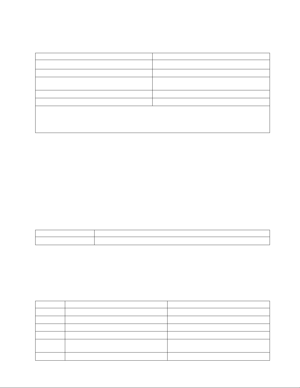
Location code topics Description
“Location code overview” on page 4 Contains background information on the use of location
codes.
“Physical location codes” on page 4 Provides a definition for physical location code.
“Logical location codes” on page 4 Provides a definition of what a logical location code is.
Finding parts, locations, and addresses 3

Location code topics Description
“Location code format” on page 5 Provides descriptive information of the Un value in the
location code string. For example, U789C.001.
“Location code labels” on page 6 Provides a table that identifies and defines the location
code labels. The location code labels begin with an
alphabetic character and follow the system serial number.
For example, U789C.001.10ABCDE-P3-C31-T2-L23. The
system serial number is 10ABCDE in the previous
example. P3, C31, T2, and L23 all contain an alphabetic
character that is identified in the Location code labels
table.
“Worldwide unique identifier” on page 6 Provides a definition for the world unique identifier. This
group of digits follows the resource code labels and
always begins with the letter W.
Location code overview
Servers (system unit and expansion units) use physical location codes to provide mapping of replaceable
units. Location codes are produced by the server's firmware, which structures them so that they can be
used to identify specific parts in a system. The location code format is the same for all servers.
If you are working with a specific location code, the unit type and model immediately follow the first
character (Utttt.mmm). Match the unit type and model to a link, as shown in the Unit type and locations
table.
If the location code ends with -Txx-Lxx, the server's firmware could not identify the physical location.
When a physical location cannot be identified, a logical location code is provided. Where logical location
codes occur in enclosures, the locations topic for the enclosure has the known conversions listed. For
logical location codes with no conversion, contact your next level of support.
If the location code begins with UTMPx, the expansion I/O unit's machine type, model, and serial
number have not been set yet and this is a temporary unit identifier. To identify the unit, examine the
display panels on all of the expansion I/O units that are connected to the server until you find one with
the same characters in the first 5 digits of the top line in the unit's display. Record the unit's real machine
type and model from the unit label. Match the unit's machine type and model in the Unit type and
locations table and follow the link to determine the service information.
Note: Locations for units that are not in the preceding list are either not supported or there is a problem
in the firmware. Contact your next level of support.
Physical location codes
Physical location codes provide a mapping of logical functions and components (such as backplanes,
removable modules, connectors, ports, cables, and devices) to their specific locations within the physical
structure of the server.
Logical location codes
If the physical location cannot be mapped to a physical location code, the server's firmware generates a
logical location code. A logical location code is a sequence of location labels that identifies the path that
the system uses to communicate with a given resource.
Note: A resource has as many logical location codes as it has logical connections to the system. For
example, an external tape device connected to two I/O adapters has two logical location codes.
4 Finding parts, locations, and addresses

An example of a logical location code is:
U789C.001.10ABCDE-P3-C31-T2-L23
The first part of the location code (through the T2 label) represents the physical location code for the
resource that communicates with the target resource. The remainder of the logical location code (L23)
represents exactly which resource is indicated.
Location code format
The location code is an alphanumeric string of variable length, consisting of a series of location
identifiers, separated by a dash. An example of a physical location for a fan is Un-A1.
The first position, represented by Un (where n is equal to any string contained between the U and the
hyphen) in the preceding example, is displayed in one of the forms in the following table.
Note: In location codes the U is a constant digit; however, the numbered positions that follow the U are
variables and are dependent on your server. Each column defines the numbers that follow the U in the
beginning of the location code.
Machine type and model number in a location code Feature codes and sequence numbers in a location code
Utttt.mmm.sssssss-A1 Uffff.ccc.sssssss-A1
The leftmost code is always U. The leftmost code is always U.
tttt represents the unit type of the enclosure (drawer or
node).
mmm represents the model of the enclosure. ccc represents the sequence number of the enclosure .
sssssss represents the serial number for the enclosure. sssssss represents the serial number of the enclosure.
Note: The mmm or ccc number might not be displayed on all location codes for all servers. If the mmm value is not
displayed, the location code is displayed in one of the following forms:
v Utttt.sssssss-A1
v Uffff.sssssss-A1
ffff represents the feature code of the enclosure (drawer
or node).
The location code is hierarchical; that is, each location identifier in the string represents a physical part.
The order (from left to right), in which each identifier is shown, allows you to determine which parts
contain other parts in the string.
The dash (-) separator character represents a relationship between two components in the unit. In the
example of the fan, whose location code is Un-A1, the dash shows that the fan (A1) is contained in the
base unit (or Un). Modules, adapters, cables, and devices are all parts that are plugged into another part.
Their location codes always show that they are plugged into another part as components of the server.
Another example follows: Un-P1-C9 is a memory DIMM (C9) that is plugged into a backplane (P1),
which is inside the unit (Un).
Note: For devices, certain error conditions might cause an IBM i device to display the device location in
an AIX®format.
Table 1. Unit type and locations
Unit type (Utttt.mmm) Link to location information
U8202.E4B or U8205.E6B 8202-E4B or 8205-E6B Locations
Finding parts, locations, and addresses 5

Location code labels
The location code label represents a physical part of the server. The following table describes the prefixes
of location code labels.
Note: These labels apply to system units only.
Table 2. Prefixes of location code labels for system units
Prefix Description Example
A Air-moving device Fan, blower
C Card connector IOP, IOA, DIMM, processor card
D Device Diskette, control panel
E Electrical Battery, power supply, ac charger
L Logical path SAS target Integrated drive electronics (IDE) address, Fibre
Channel LUN
N Horizontal placement for an empty rack location
P Planar System backplane
T Port, external cable
U Unit
V Virtual planar
W Worldwide unique ID
X EIA value for an empty rack location
Y Firmware FRU
Worldwide unique identifier
The location code label for the worldwide unique identifier consists of the prefix W followed by a
maximum of 16 uppercase hexadecimal digits with no leading zeros. A location code might not consist of
a worldwide unique identifier. When present, the worldwide unique identifier location label follows the
location label of the resource that interfaces with the resource that has the worldwide unique identifier,
usually a port.
8202-E4B or 8205-E6B locations
Use this information to help you map a location code to a position on the unit.
The following diagrams show field replaceable unit (FRU) layouts in the system. Use these diagrams with
the following tables.
Rack views
6 Finding parts, locations, and addresses
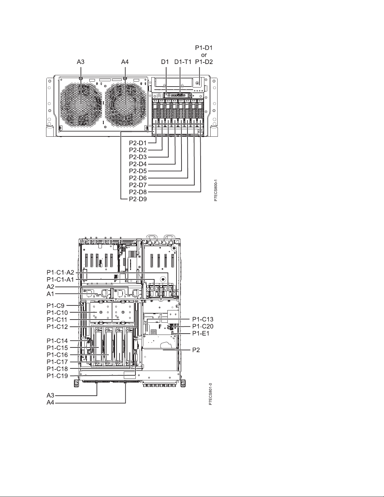
Figure 1. Rack front view
Figure 2. Rack top view
Finding parts, locations, and addresses 7
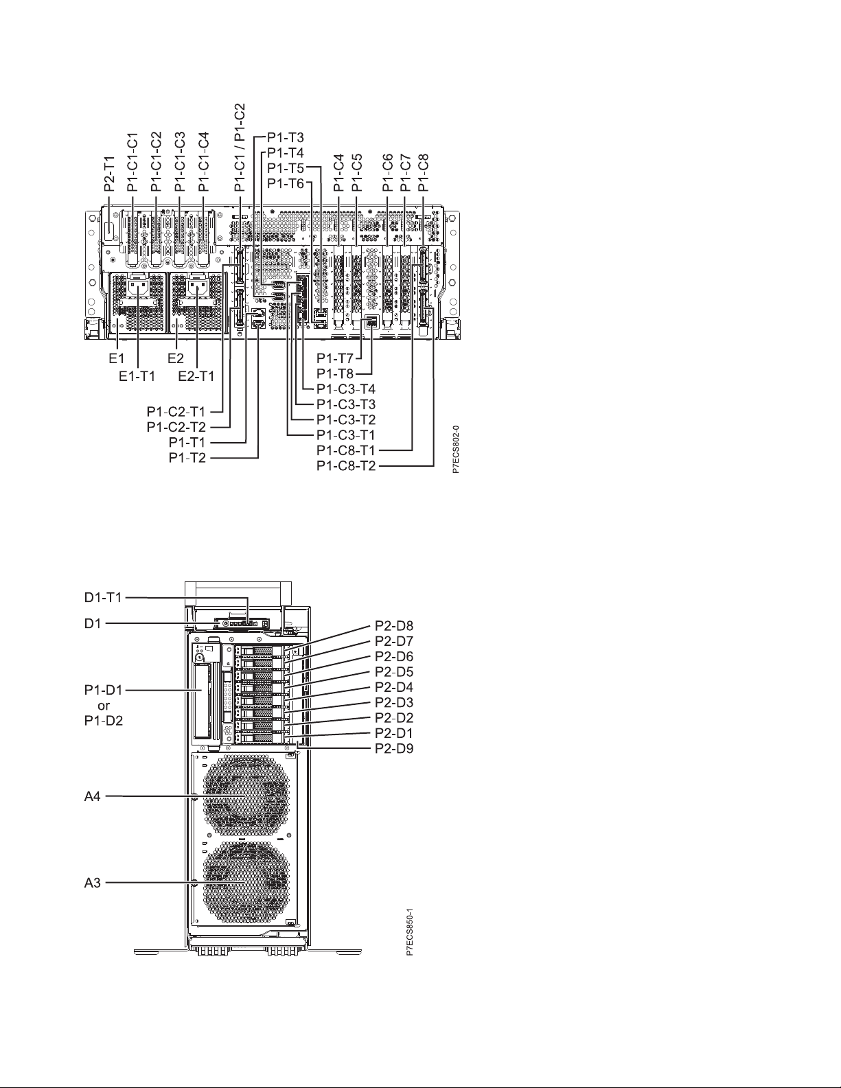
Figure 3. Rack rear view
Stand-alone views
Figure 4. Stand-alone front view
8 Finding parts, locations, and addresses

Figure 5. Stand-alone side view
Figure 6. Stand-alone rear view
Memory card locations
Finding parts, locations, and addresses 9

Figure 7. Memory card locations
PCIe SAS RAID and SSD adapter locations
Figure 8. PCIe SAS RAID and SSD adapter locations
The following table provides location codes for parts that comprise the server.
Table 3. FRU location
Failing item name Physical location code Identify LED
System unit Un
10 Finding parts, locations, and addresses
Failing item
removal and
replacement
procedures

Table 3. FRU location (continued)
Failing item
removal and
replacement
Failing item name Physical location code Identify LED
procedures
Fans
Fan 1 Un-A1 Yes See Fans.
Fan 2 Un-A2 Yes
Fan 3 Un-A3 Yes
Fan 4 Un-A4 Yes
Power supplies
Power supply 1 Un-E1 Yes See Power
Power supply 1 - Cord connector Un-E1-T1 Yes
supply.
Power supply 2 Un-E2 Yes
Power supply 2 - Cord connector Un-E2-T1 Yes
Backplanes
System backplane Un-P1 Yes See System
backplane.
Time-of-day Un-P1
Time-of-day battery Un-P1-E1 See Time-of-day
battery.
Disk drive backplane Un-P2 Yes See Disk drive
backplane.
Ports
System port 1 Un-P1-T1 No
System port 2 Un-P1-T2 No
SPCN port 1 Un-P1-T3 No
SPCN port 2 Un-P1-T4 No
HMC port 1 Un-P1-T5 No
HMC port 2 Un-P1-T6 No
USB port 1 Un-P1-T7 No
USB port 2 Un-P1-T8 No
Processor and processor regulator
POWER7 processor module 1 Un-P1-C11 Yes See System
POWER7 processor module 2 Un-P1-C10 Yes
processor
module.
POWER7 processor module 1 VRM Un-P1-C12 Yes See Voltage
POWER7 processor module 2 VRM Un-P1-C9 Yes
regulator module.
Adapters
PCIe riser Un-P1-C1 No
PCIe expansion feature - PCIe x8 slot 5 Un-P1-C1-C1 No
PCIe expansion feature - PCIe x8 slot 6 Un-P1-C1-C2 No
PCIe expansion feature - PCIe x8 slot 7 Un-P1-C1-C3 No
PCIe expansion feature - PCIe x8 slot 8 Un-P1-C1-C4 No
Finding parts, locations, and addresses 11
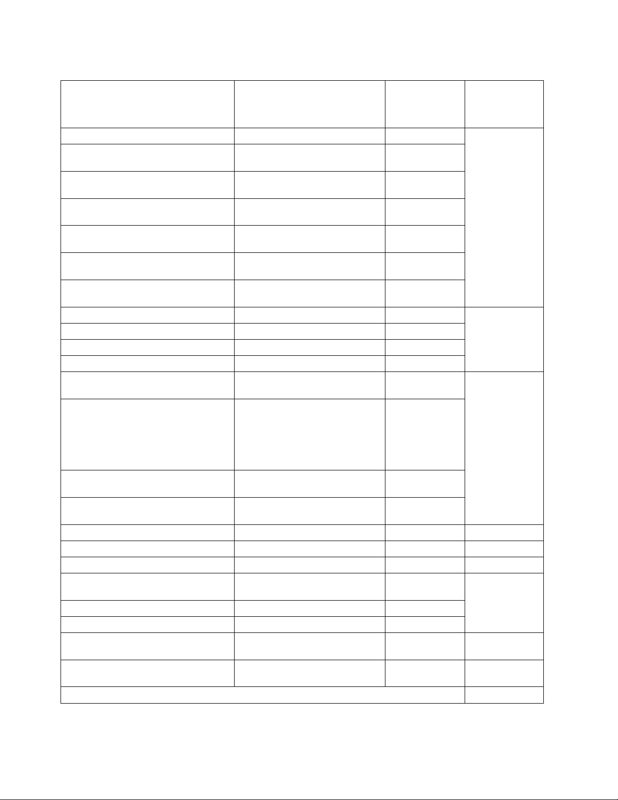
Table 3. FRU location (continued)
Failing item
removal and
replacement
Failing item name Physical location code Identify LED
Host Ethernet Adapter slot Un-P1-C3 Yes See Host Ethernet
Host Ethernet Adapter 4-Port 1 Gb card
- Port 1
Host Ethernet Adapter 4-Port 1 Gb card
- Port 2
Host Ethernet Adapter 4-Port 1 Gb card
- Port 3
Host Ethernet Adapter 4-Port 1 Gb card
- Port 4
Host Ethernet Adapter 2-Port 10 Gb card
- Port 1
Host Ethernet Adapter 2-Port 10 Gb card
- Port 2
PCIe slot 1 Un-P1-C4 No See PCI
PCIe slot 2 Un-P1-C5 No
PCIe slot 3 Un-P1-C6 No
PCIe slot 4 Un-P1-C7 No
GX Dual-Port 12X Channel Attach
adapter
GX Dual-Port 12X Channel Attach
adapter
Note: You can either install the GX
Dual-Port 12X Channel Attach adapter
in Un-P1-C2 or the PCIe riser in
Un-P1-C1, but not both at the same time.
GX Dual-Port 12X Channel Attach
adapter IB-2 card - Port 1
GX Dual-Port 12X Channel Attach
adapter IB-2 card - Port 2
PCIe expansion feature - Fan 1 Un-P1-C1-A1 Yes
PCIe expansion feature - Fan 2 Un-P1-C1-A2 Yes
System VPD card Un-P1-C20
RAID enablement card for system
backplane
Cache battery card Un-P1-C14 Yes
Battery on cache battery card Un-P1-C14-E1 Yes
RAID storage controller or RAID and
cache storage controller
Battery on RAID and cache storage
controller
Memory modules
Un-P1-C3-T1 Yes
Un-P1-C3-T2 Yes
Un-P1-C3-T3 Yes
Un-P1-C3-T4 Yes
Un-P1-C3-T1 Yes
Un-P1-C3-T2 Yes
Un-P1-C8 Yes See GX++ 12X
Un-P1-C2
Un-P1-C8-T1 Yes
Un-P1-C8-T2 Yes
Un-P1-C13 Yes See SAS RAID
Un-P1-C19 Yes
Un-P1-C19-E1 Yes
procedures
adapter.
Adapters.
channel adapters.
enablement and
cache battery
pack.
12 Finding parts, locations, and addresses
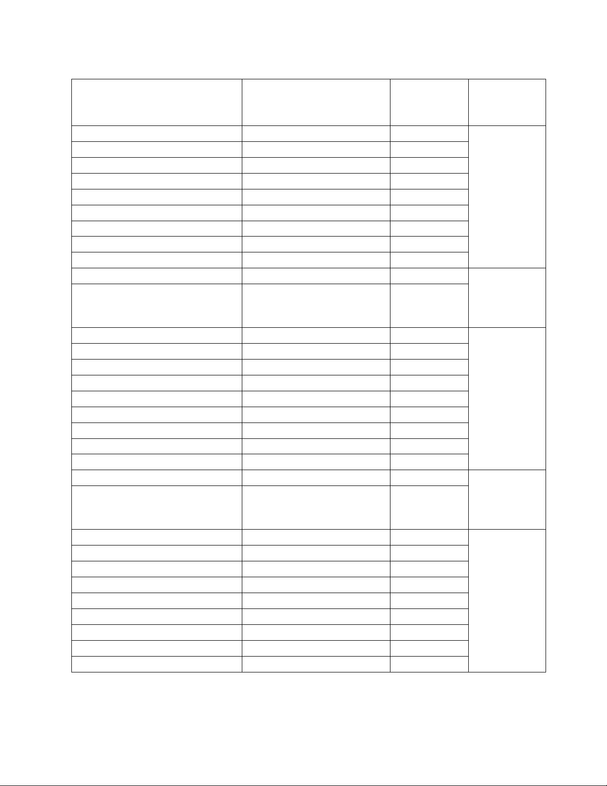
Table 3. FRU location (continued)
Failing item
removal and
replacement
Failing item name Physical location code Identify LED
procedures
Memory card 1 Un-P1-C18 Yes See Memory
Memory card 1 - DIMM 1 Un-P1-C18-C1 Yes
modules.
Memory card 1 - DIMM 2 Un-P1-C18-C2 Yes
Memory card 1 - DIMM 3 Un-P1-C18-C3 Yes
Memory card 1 - DIMM 4 Un-P1-C18-C4 Yes
Memory card 1 - DIMM 5 Un-P1-C18-C7 Yes
Memory card 1 - DIMM 6 Un-P1-C18-C8 Yes
Memory card 1 - DIMM 7 Un-P1-C18-C9 Yes
Memory card 1 - DIMM 8 Un-P1-C18-C10 Yes
Memory card 1 - 20A memory VRM Un-P1-C18-C5 Yes See Memory
Memory card 1 - 80A memory VRM Un-P1-C18-C6 Yes
voltage regulator
module for the
8202-E4B or
8205-E6B.
Memory card 2 Un-P1-C17 Yes See Memory
Memory card 2 - DIMM 1 Un-P1-C17-C1 Yes
modules.
Memory card 2 - DIMM 2 Un-P1-C17-C2 Yes
Memory card 2 - DIMM 3 Un-P1-C17-C3 Yes
Memory card 2 - DIMM 4 Un-P1-C17-C4 Yes
Memory card 2 - DIMM 5 Un-P1-C17-C7 Yes
Memory card 2 - DIMM 6 Un-P1-C17-C8 Yes
Memory card 2 - DIMM 7 Un-P1-C17-C9 Yes
Memory card 2 - DIMM 8 Un-P1-C17-C10 Yes
Memory card 2 - 20A memory VRM Un-P1-C17-C5 Yes See Memory
Memory card 2 - 80A memory VRM Un-P1-C17-C6 Yes
voltage regulator
module for the
8202-E4B or
8205-E6B.
Memory card 3 Un-P1-C16 Yes See Memory
Memory card 3 - DIMM 1 Un-P1-C16-C1 Yes
modules.
Memory card 3 - DIMM 2 Un-P1-C16-C2 Yes
Memory card 3 - DIMM 3 Un-P1-C16-C3 Yes
Memory card 3 - DIMM 4 Un-P1-C16-C4 Yes
Memory card 3 - DIMM 5 Un-P1-C16-C7 Yes
Memory card 3 - DIMM 6 Un-P1-C16-C8 Yes
Memory card 3 - DIMM 7 Un-P1-C16-C9 Yes
Memory card 3 - DIMM 8 Un-P1-C16-C10 Yes
Finding parts, locations, and addresses 13

Table 3. FRU location (continued)
Failing item
removal and
replacement
Failing item name Physical location code Identify LED
Memory card 3 - 20A memory VRM Un-P1-C16-C5 Yes See Memory
Memory card 3 - 80A memory VRM Un-P1-C16-C6 Yes
Memory card 4 Un-P1-C15 Yes See Memory
Memory card 4 - DIMM 1 Un-P1-C15-C1 Yes
Memory card 4 - DIMM 2 Un-P1-C15-C2 Yes
Memory card 4 - DIMM 3 Un-P1-C15-C3 Yes
Memory card 4 - DIMM 4 Un-P1-C15-C4 Yes
Memory card 4 - DIMM 5 Un-P1-C15-C7 Yes
Memory card 4 - DIMM 6 Un-P1-C15-C8 Yes
Memory card 4 - DIMM 7 Un-P1-C15-C9 Yes
Memory card 4 - DIMM 8 Un-P1-C15-C10 Yes
Memory card 4 - 20A memory VRM Un-P1-C15-C5 Yes See Memory
Memory card 4 - 80A memory VRM Un-P1-C15-C6 Yes
Device physical locations
Tape drive (SAS) Un-P1-D1 No
Tape drive (USB) Un-P1-D2 No
Disk drive 1 Un-P2-D1 Yes See Disk drives.
Disk drive 2 Un-P2-D2 Yes
Disk drive 3 Un-P2-D3 Yes
Disk drive 4 Un-P2-D4 Yes
Disk drive 5 Un-P2-D5 Yes
Disk drive 6 Un-P2-D6 Yes
Disk drive 7 Un-P2-D7 Yes
Disk drive 8 Un-P2-D8 Yes
Solid-state disk drive 1 on PCIe SAS
RAID and SSD adapter
Solid-state disk drive 2 on PCIe SAS
RAID and SSD adapter
Solid-state disk drive 3 on PCIe SAS
RAID and SSD adapter
Solid-state disk drive 4 on PCIe SAS
RAID and SSD adapter
DVD Un-P2-D9 Yes
SAS port Un-P2-T1 No
Embedded SAS controller Un-P1-T9 No
Un -P1-Cx-D1 or Un -P1-C1-Cx-D1 No
Un -P1-Cx-D2 or Un -P1-C1-Cx-D2 No
Un -P1-Cx-D3 or Un -P1-C1-Cx-D3 No
Un -P1-Cx-D4 or Un -P1-C1-Cx-D4 No
procedures
voltage regulator
module for the
8202-E4B or
8205-E6B.
modules.
voltage regulator
module for the
8202-E4B or
8205-E6B.
14 Finding parts, locations, and addresses

Table 3. FRU location (continued)
Failing item
removal and
replacement
Failing item name Physical location code Identify LED
Control panel
Control panel Un -D1 No See Control panel
Temperature sensor Un -D1 No
Control panel - USB port Un -D1-T1 No
Server firmware
Server firmware Um-Y1
procedures
and signal cables
for the 8202-E4B
or 8205-E6B
systems.
Related reference:
8202-E4B or 8205-E6B system parts
Indexed drawings show system part numbers for each part.
8202-E4C, 8202-E4D, 8205-E6C, or 8205-E6D
The information provided in this topic defines specific sections of a location code string. Use this
information to understand the meaning of a location code.
Using location codes
Use the following table to link to a specific topic that you need additional information about when
reading your location code.
Location code topics Description
“Location code overview” on page 16 Contains background information on the use of location
codes.
“Physical location codes” on page 16 Provides a definition for physical location code.
“Logical location codes” on page 16 Provides a definition of what a logical location code is.
“Location code format” on page 16 Provides descriptive information of the Un value in the
location code string. For example, U789C.001.
“Location code labels” on page 17 Provides a table that identifies and defines the location
code labels. The location code labels begin with an
alphabetic character and follow the system serial number.
For example, U789C.001.10ABCDE-P3-C31-T2-L23. The
system serial number is 10ABCDE in the previous
example. P3, C31, T2, and L23 all contain an alphabetic
character that is identified in the Location code labels
table.
“Worldwide unique identifier” on page 18 Provides a definition for the world unique identifier. This
group of digits follows the resource code labels and
always begins with the letter W.
Finding parts, locations, and addresses 15

Location code overview
Servers (system unit and expansion units) use physical location codes to provide mapping of replaceable
units. Location codes are produced by the server's firmware, which positions them so that they can be
used to identify specific parts in a system. The location code format is the same for all servers.
If you are working with a specific location code, the unit type and model immediately follow the first
character (Utttt.mmm). Match the unit type and model to a link, as shown in the Unit type and locations
table.
If the location code ends with -Txx-Lxx, the server's firmware could not identify the physical location.
When a physical location cannot be identified, a logical location code is provided. Where logical location
codes occur in enclosures, the locations topic for the enclosure has the known conversions listed. For
logical location codes with no conversion, contact your next level of support.
If the location code begins with UTMPx, the machine type, model, and serial number of the expansion
I/O unit have not been set yet, and this is a temporary unit identifier. To identify the unit, examine the
display panels on all of the expansion I/O units that are connected to the server until you find one with
the same characters in the first 5 digits of the top line in the unit's display. Record the unit's real machine
type and model from the unit label. Match the unit's machine type and model in the Unit type and
locations table and follow the link to determine the service information.
Note: Locations for units that are not in the preceding list are either not supported or there is a problem
in the firmware. Contact your next level of support.
Physical location codes
Physical location codes provide a mapping of logical functions and components (such as backplanes,
removable modules, connectors, ports, cables, and devices) to their specific locations within the physical
structure of the server.
Logical location codes
If the physical location cannot be mapped to a physical location code, the server's firmware generates a
logical location code. A logical location code is a sequence of location labels that identifies the path that
the system uses to communicate with a given resource.
Note: A resource has as many logical location codes as it has logical connections to the system. For
example, an external tape device connected to two I/O adapters has two logical location codes.
An example of a logical location code is:
U789C.001.10ABCDE-P3-C31-T2-L23
The first part of the location code (through the T2 label) represents the physical location code for the
resource that communicates with the target resource. The remainder of the logical location code (L23)
represents which resource is indicated.
Location code format
The location code is an alphanumeric string of variable length, consisting of a series of location
identifiers, separated by a dash. An example of a physical location for a fan is Un-A1.
The first position, represented by Un (where n is equal to any string contained between the U and the
hyphen) in the preceding example, is displayed in one of the forms in the following table.
16 Finding parts, locations, and addresses
Note: In location codes the U is a constant digit; however, the numbered positions that follow the U are
variables and are dependent on your server. Each column defines the numbers that follow the U in the
beginning of the location code.
Machine type and model number in a location code Feature codes and sequence numbers in a location code
Utttt.mmm.sssssss-A1 Uffff.ccc.sssssss-A1
The leftmost code is always U. The leftmost code is always U.
tttt represents the unit type of the enclosure (drawer or
node).
mmm represents the model of the enclosure. ccc represents the sequence number of the enclosure .
sssssss represents the serial number for the enclosure. sssssss represents the serial number of the enclosure.
Note: The mmm or ccc number might not be displayed on all location codes for all servers. If the mmm value is not
displayed, the location code is displayed in one of the following forms:
v Utttt.sssssss-A1
v Uffff.sssssss-A1
ffff represents the feature code of the enclosure (drawer
or node).
The location code is hierarchical; that is, each location identifier in the string represents a physical part.
The order (from left to right), in which each identifier is shown, helps you determine which parts contain
other parts in the string.
The dash (-) separator character represents a relationship between two components in the unit. In the
example of the fan, whose location code is Un-A1, the dash shows that the fan (A1) is contained in the
base unit (or Un). Modules, adapters, cables, and devices are all parts that are plugged into another part.
Their location codes always show that they are plugged into another part as components of the server.
Another example follows: Un-P1-C9 is a memory DIMM (C9) that is plugged into a backplane (P1),
which is inside the unit (Un).
Note: For devices, certain error conditions might cause an IBM i device to display the device location in
an AIX format.
Table 4. Unit type and locations
Unit type (Utttt.mmm) Link to location information
U78AA.001 8202-E4C, 8202-E4D, 8205-E6C, or 8205-E6D locations
Location code labels
The location code label represents a physical part of the server. The following table describes the prefixes
of location code labels.
Note: These labels apply to system units only.
Table 5. Prefixes of location code labels for system units
Prefix Description Example
A Air-moving device Fan, blower
C Card connector IOP, IOA, DIMM, processor card
D Device Diskette, control panel
E Electrical Battery, power supply, ac charger
L Logical path SAS target Integrated drive electronics (IDE) address, Fibre
Channel LUN
N Horizontal placement for an empty rack location
Finding parts, locations, and addresses 17
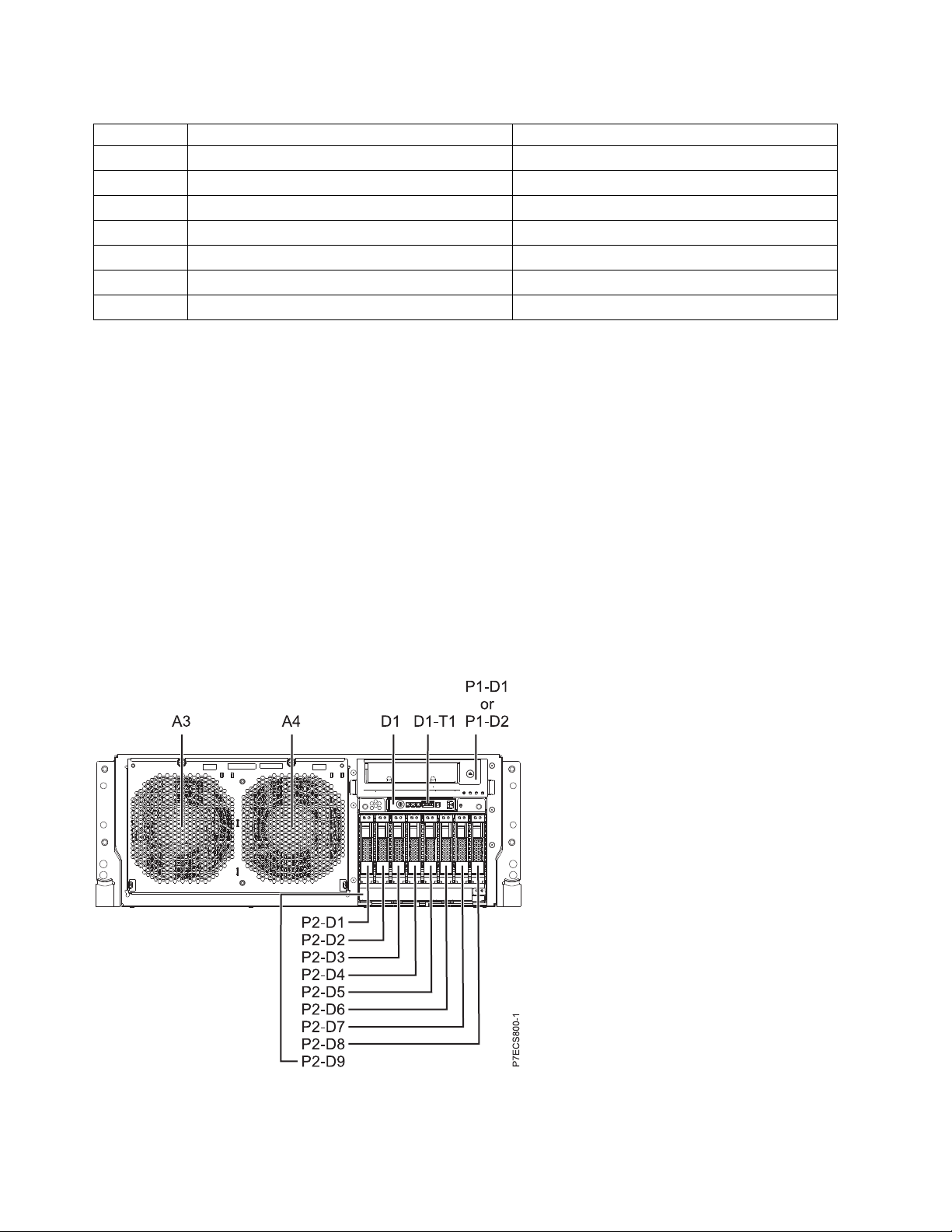
Table 5. Prefixes of location code labels for system units (continued)
Prefix Description Example
P Planar System backplane
T Port, external cable
U Unit
V Virtual planar
W Worldwide unique ID
X EIA value for an empty rack location
Y Firmware FRU
Worldwide unique identifier
The location code label for the worldwide unique identifier consists of the prefix W followed by a
maximum of 16 uppercase hexadecimal digits with no leading zeros. A location code might not consist of
a worldwide unique identifier. When present, the worldwide unique identifier location label follows the
location label of the resource that interfaces with the resource that has the worldwide unique identifier,
usually a port.
8202-E4C, 8202-E4D, 8205-E6C, or 8205-E6D locations
Use this information to help you map a location code to a position on the unit.
The following diagrams show field replaceable unit (FRU) layouts in the system. Use these diagrams with
the following tables.
Rack views
Figure 9. Rack front view
18 Finding parts, locations, and addresses
Loading...