


 Loading...
Enterprise Server S80 |
IBM |
pSeries 680 Model S85 |
Installation Guide
SA38-0582-00
First Edition (November 2000)
Before using this information and the product it supports, read the information in ªSafety Noticesº on page v,
ªAppendix B. Environmental Noticesº on page 43, and ªAppendix C. Noticesº on page 45.
© International Business Machines Corporation 2000. All rights reserved.
Note to U.S. Government Users - Documentation related to restricted rights - Use, duplication, or disclosure is subject to the restrictions set forth in the GSA ADP Schedule Contract with IBM Corp.

Contents
Safety Notices . . . . . . |
. . . |
. . . . . . . . . . . |
. . |
. |
. |
v |
Electrical Safety . . . . . . |
. . . |
. . . . . . . . . . . |
. . |
. |
. |
v |
Laser Safety Information . . . |
. . . |
. . . . . . . . . . . |
. . |
. |
. |
vi |
Data Integrity and Verification . |
. . . |
. . . . . . . . . . |
. . |
. |
. |
vii |
About This Book . . . . . |
. . . |
. . . . . . . . . . . |
. . |
. |
. |
ix |
ISO 9000 . . . . . . . . |
. . . |
. . . . . . . . . . . |
. . |
. |
. |
ix |
Online Publications. . . . . |
. . . |
. . . . . . . . . . . |
. . |
. |
. |
ix |
Related Publications . . . . . . . . . . . . . . . . . . . . . . ix
Trademarks . . . . . . . . . . . . . . . . . . . . . . . |
. |
. |
x |
|
Chapter 1. System Installation Procedure . . . . . . . . . . . . |
. |
. |
1 |
|
Step 1. Inventory . . . . . . . . . . . . . . . . . . . . . |
. |
. |
1 |
|
Step 2. |
Observe this Safety Notice During Installation . . . . . . . . . |
. |
. |
1 |
Step 3. |
Check the Customer Environment . . . . . . . . . . . . . |
. |
. |
2 |
Step 4. |
Check Customer Outlets . . . . . . . . . . . . . . . . |
. |
. |
3 |
Step 5. |
Set Up the System Racks . . . . . . . . . . . . . . . . |
. |
. |
4 |
Step 6A. Attach the I/O Rack to a Concrete Floor . . . . . . . . . . . |
. |
. |
7 |
|
Attaching the I/O Rack to a Concrete Floor . . . . . . . . . . . . |
. |
. |
8 |
|
Attaching the I/O Rack to a Concrete Floor Beneath a Raised Floor . . . . |
. |
10 |
||
Step 6B. Attach the System Rack to a Concrete Floor . . . . . . . . . . |
. |
14 |
||
Attaching the System Rack to a Concrete Floor . . . . . . . . . . . . |
. |
15 |
||
Attaching the System Rack to a Concrete Floor Beneath a Raised Floor. . . . . 16
Step 7. Attach the Front Electrical Outlet . . . . . . . . . . . . . |
. |
. |
18 |
Step 8. Attach the Rear Electrical Outlet . . . . . . . . . . . . . |
. |
. |
22 |
Step 9. Remove the Shipping Brackets and Install Covers . . . . . . . |
. |
. |
26 |
Step 10. Install the I/O Rack Door Guide . . . . . . . . . . . . . |
. |
. |
27 |
Step 11. Connect the Operator Panel Cable and the JTAG Cable Between the |
|
|
|
Racks . . . . . . . . . . . . . . . . . . . . . . . . |
. |
. |
28 |
Step 12. Connect RIO and SPCN Cables Between the Racks . . . . . . |
. |
. 28 |
|
Step 13. Set Up Attached Devices . . . . . . . . . . . . . . . |
. |
. |
28 |
Step 14. Update the Device Records . . . . . . . . . . . . . . |
. |
. |
29 |
Step 15. Attach External Devices . . . . . . . . . . . . . . . . |
. |
. |
29 |
Step 16. Connect the Power . . . . . . . . . . . . . . . . . |
. |
. |
29 |
Step 17. Power On and Check Out the System . . . . . . . . . . . |
. |
. |
29 |
Checklist If Problems Occur . . . . . . . . . . . . . . . . . |
. |
. |
29 |
Step 18. Service Processor Setup and Test . . . . . . . . . . . . |
. |
. |
30 |
Step 19. Install the Modem and Electronic Service Agent . . . . . . . . |
. |
. |
30 |
Step 20. Finish the Installation . . . . . . . . . . . . . . . . |
. |
. |
30 |
Chapter 2. Using the System Verification Procedure . . . . . . . . |
. |
. |
33 |
Chapter 3. Installing Options for Your System . . . . . . . . . . |
. |
. |
37 |
Appendix A. Communications Statements . . . . . . . . . . . . |
. |
. |
39 |
Federal Communications Commission (FCC) Statement . . . . . . . . |
. |
. |
39 |
iii
European Union (EU) Statement . . . . . . . . . . . |
. . . . |
. . |
. |
39 |
International Electrotechnical Commission (IEC) Statement . . |
. . . . |
. . |
. |
40 |
United Kingdom Telecommunications Safety Requirements . . |
. . . . |
. . |
. |
40 |
Avis de conformité aux normes du ministère des Communications du Canada . . . 40
Canadian Department of Communications Compliance Statement . . . |
. . |
. |
. |
40 |
VCCI Statement . . . . . . . . . . . . . . . . . . . . . . . 40 |
||||
Electromagnetic Interference (EMI) Statement - Taiwan . . . . . . |
. . |
. |
. |
41 |
Radio Protection for Germany . . . . . . . . . . . . . . . |
. . |
. |
. |
41 |
Appendix B. Environmental Notices . . . . . . . . . . . . |
. . |
. |
. |
43 |
Product Recycling and Disposal . . . . . . . . . . . . . . |
. . |
. |
. |
43 |
Environmental Design . . . . . . . . . . . . . . . . . |
. . |
. |
. |
43 |
Unit Emissions . . . . . . . . . . . . . . . . . . . . . . . . 43 |
||||
Appendix C. Notices . . . . . . . . . . . . . . . . . |
. . |
. |
. |
45 |
Appendix D. Cabling the System Rack and I/O Rack . . . . . . |
. . |
. |
. |
47 |
Connecting JTAG and Operator Panel Cables . . . . . . . . . |
. . |
. |
. |
48 |
I/O Rack Rear Locations . . . . . . . . . . . . . . . . |
. . |
. |
. |
49 |
I/O Drawer Locations . . . . . . . . . . . . . . . . . . |
. . |
. |
. |
50 |
10 EIA Unit I/O Drawer Front View . . . . . . . . . . . . |
. . |
. |
. |
50 |
10 EIA Unit I/O Drawer Rear View . . . . . . . . . . . . |
. . |
. |
. |
51 |
10 EIA Unit I/O Drawer System board Locations . . . . . . . . |
. . |
. |
. |
53 |
Service Processor Card Locations . . . . . . . . . . . . |
. . |
. |
. |
55 |
Fan Monitor Control (FMC) Card Locations (10 EIA Unit I/O Drawer) . . . . . 56 |
||||
Power Distribution Board Locations . . . . . . . . . . . . |
. . |
. |
. |
56 |
Connecting RIO and SPCN Cables . . . . . . . . . . . . . |
. . |
. |
. |
57 |
Appendix E. System Records . . . . . . . . . . . . . . |
. . |
. |
. |
63 |
Record the Identification Numbers . . . . . . . . . . . . . |
. . |
. |
. |
63 |
S80 and S85 System Rack . . . . . . . . . . . . . . . |
. . |
. |
. |
63 |
S80 and S85 System Rack Memory Configuration . . . . . . . |
. . |
. |
. |
63 |
S80 and S85 System Rack Cabling Configurations - RIO Cabling . . |
. . |
. |
. |
63 |
S80 and S85 System Rack Cabling Configurations - SPCN Cabling . |
. . |
. |
. 64 |
|
Primary I/O Drawer Device Records . . . . . . . . . . . . . |
. . |
. |
. |
65 |
Additional I/O Drawer Device Records . . . . . . . . . . . . |
. . |
. |
. |
68 |
Index . . . . . . . . . . . . . . . . . . . . . . . |
. . |
. |
. |
71 |
Reader's Comments Ð We'd Like to Hear From You . . . . . . |
. . |
. |
. |
73 |
iv S80, S85 Installation Guide

Safety Notices
A danger notice indicates the presence of a hazard that has the potential of causing death or serious personal injury.
A caution notice indicates the presence of a hazard that has the potential of causing moderate or minor personal injury.
Electrical Safety
Observe the following safety instructions any time you are connecting or disconnecting devices attached to the workstation.
DANGER
An electrical outlet that is not correctly wired could place hazardous voltage on metal parts of the system or the devices that attach to the system. It is the responsibility of the customer to ensure that the outlet is correctly wired and grounded to prevent an electrical shock.
Before installing or removing signal cables, ensure that the power cables for the system unit and all attached devices are unplugged.
When adding or removing any additional devices to or from the system, ensure that the power cables for those devices are unplugged before the signal cables are connected. If possible, disconnect all power cables from the existing system before you add a device.
Use one hand, when possible, to connect or disconnect signal cables to prevent a possible shock from touching two surfaces with different electrical potentials.
During an electrical storm, do not connect cables for display stations, printers, telephones, or station protectors for communication lines.
CAUTION:
This product is equipped with a three±wire power cable and plug for the user's safety. Use this power cable with a properly grounded electrical outlet to avoid electrical shock.
DANGER
To prevent electrical shock hazard, disconnect the power cable
CAUTION:
This unit has more than one power supply cord. To reduce the risk of electrical shock, disconnect two power supply cords before servicing.
v
Laser Safety Information
The optical drive in this system unit is a laser product. The optical drive has a label that identifies its classification. The label, located on the drive, is shown below.
CLASS 1 LASER PRODUCT
LASER KLASSE 1
LUOKAN 1 LASERLAITE
APPAREIL A LASER DE CLASSE 1
IEC 825:1984 CENELEC EN 60 825:1991
The optical drive in this system unit is certified in the U.S. to conform to the requirements of the Department of Health and Human Services 21 Code of Federal Regulations (DHHS 21 CFR) Subchapter J for Class 1 laser products. Elsewhere, the drive is certified to conform to the requirements of the International Electrotechnical Commission (IEC) 825 (1st edition 1984) and CENELEC EN 60 825:1991 for Class 1 laser products.
CAUTION:
A class 3 laser is contained in the device. Do not attempt to operate the drive while it is disassembled. Do not attempt to open the covers of the drive as it is not serviceable and is to be replaced as a unit.
Class 1 laser products are not considered to be hazardous. The optical drive contains internally a Class 3B gallium-arsenide laser that is nominally 30 milliwatts at 830 nanometers. The design incorporates a combination of enclosures, electronics, and redundant interlocks such that there is no exposure to laser radiation above a Class 1 level during normal operation, user maintenance, or servicing conditions.
vi S80, S85 Installation Guide

Data Integrity and Verification
IBM computer systems contain mechanisms designed to reduce the possibility of undetected data corruption or loss. This risk, however, cannot be eliminated. Users who experience unplanned outages, system failures, power fluctuations or outages, or component failures must verify the accuracy of operations performed and data saved or transmitted by the system at or near the time of the outage or failure. In addition, users must establish procedures to ensure that there is independent data verification before relying on such data in sensitive or critical operations. Users should periodically check the IBM support websites for updated information and fixes applicable to the system and related software.
vii
viii S80, S85 Installation Guide

About This Book
This book provides information on how to setup and install the system, use diagnostics, use service aids, and verify system operation. This book also provides information to help you solve some of the simpler problems that might occur.
ISO 9000
ISO 9000 registered quality systems were used in the development and manufacturing of this product.
Online Publications
RS/6000 publications are available online. To access the online books, visit our Web site at: http://www.rs6000.ibm.com/resource/hardware_docs/
Related Publications
The following publications are available:
vThe Enterprise Server S80, p Series 680 Model S85 Service Guide, order number SA38-0560, contains reference information, maintenance analysis procedures (MAPs), error codes, removal and replacement procedures, and a parts catalog.
vThe Diagnostic Information for Multiple Bus Systems, order number SA38-0509, contains diagnostic information, service request numbers (SRNs), and failing function codes (FFCs).
vThe IBM RS/6000 Adapters, Devices, and Cable Information for Multiple Bus Systems, order number SA38-0516 contains information about adapters, devices, and cables for your system. This manual is intended to supplement the service information found in the Diagnostic Information for Multiple Bus Systems.
vThe Site and Hardware Planning Information, order number SA38-0508, contains specifications to help you do space and environmental planning before your system is installed.
vThe PCI Adapter Placement Reference, order number SA38-0538, contains information about slot requirements for installing PCI adapters. This book is intended to be used to help plan and install PCI adapters for maximum performance from your system.
vSSA Adapters User's Guide and Maintenance Information, order number SA33-3272, is intended to help users and service representatives work with and diagnose problems with SSA adapters and devices.
vThe High Availability Cluster Multi-Processing for AIX, Version 4.3: Enhanced Scalability Installation and Administration Guide, order number SC23-4284, is needed for HACMP/ES planning information.
vThe High Availability Cluster Multi-Processing for AIX, Version 4.3: Planning Guide, order number SC23-4277, is needed for HACMP/ES planning information.
ix

vThe 7133 SSA Disk System: Operator Guide, order number xxxxxxx, describes how to operate the 7133 SSA Disk System and how to install or replace disk drives to the system, and how to deal with problems encountered when using the system.
vThe 7133 SSA Disk Subsystem: Service Guide, order number xxxxxxx, is used by the service technician to repair system failures in the 7133 SSA Disk System.
Trademarks
The following trademarks apply to this information:
vAIX is a registered trademark of the International Business Machines Corporation.
vIBM is a registered trademark of the International Business Machines Corporation.
vVelcro is a trademark of Velcro Industries.
x S80, S85 Installation Guide
Chapter 1. System Installation Procedure
Follow the procedures in this chapter to install the Enterprise Server S80 and the p Series 680 Model S85. The estimated installation time for the system is:
Install Activity |
3.5 Hours |
Planning Activity |
2.0 Hours |
________________ |
_________ |
Total Time |
5.5 Hours |
Step 1. Inventory
vThe About Your Machine listing is in a plastic bag attached to the outside of the carton. Check the listing to verify that you have all the items that were shipped with the system.
vAIX operating system publications
vEnterprise Server S80, p Series 680 Model S85 User's Guide, order number SA38-0557
vEnterprise Server S80, p Series 680 Model S85 Service Guide, SA38-0560
vEnterprise Server S80, p Series 680 Model S85 Installation Guide, order number SA38-0582 (this book)
vDiagnostic Information for Multiple Bus Systems, order number SA38-0509
vIBM RS/6000 Adapters, Devices, and Cable Information for Multiple Bus Systems, order number SA38-0516
vPCI Adapter Placement Reference, order number SA38-0538.
vSystem Unit Safety Information, order number SA23-2652
vElectronic Service Agent for RS/6000 User's Guide, order number ZA38-0383
vSupport Information and Warranty.
Verify with the customer that the following items are available. You will need them to complete this installation.
1.A floor plan, showing where to place each rack.
2.A console, including cables and a power source.
3.A modem for the electronic customer-support function (if the customer ordered this function). This includes the correct telephone jack, cables, and a power source.
Step 2. Observe this Safety Notice During Installation
Note: For a translation of this notice, see the System Unit Safety Information manual.
1

DANGER
An electrical outlet that is not correctly wired could place hazardous voltage on metal parts of the system or the devices that attach to the system. It is the responsibility of the customer to ensure that the outlet is correctly wired and grounded to prevent an electrical shock.
Before installing or removing signal cables, ensure that the power cables for the system unit and all attached devices are unplugged.
When adding or removing any additional devices to or from the system, ensure that the power cables for those devices are unplugged before the signal cables are connected. If possible, disconnect all power cables from the existing system before you add a device.
Use one hand, when possible, to connect or disconnect signal cables to prevent a possible shock from touching two surfaces with different electrical potentials.
During an electrical storm, do not connect cables for display stations, printers, telephones, or station protectors for communication lines.
CAUTION:
This product is equipped with a three±wire power cable and plug for the user's safety. Use this power cable with a properly grounded electrical outlet to avoid electrical shock.
CAUTION:
This unit has more than one power supply cord. To reduce the risk of electrical shock, disconnect two power supply cords before servicing.
CAUTION:
Energy hazard, remove power before servicing. Disconnect two power supply cords.
Step 3. Check the Customer Environment
1.Verify with your Installation Planning Representative or the customer that any station-protector boxes used are correctly installed according to the Site and Hardware Planning Information manual.
2.Make sure the customer is aware that the recommended temperature for IBM products is 24° C (75° F) and the recommended relative humidity is 45%. The
acceptable operating temperature range is 10° C (50° F) to 38° C (100° F), and the acceptable operating humidity range is 8% to 80%.
3.Make sure the customer is aware that the front and rear service clearances around the system rack and I/O rack should be 36 inches (900mm). The service clearances are important for proper air circulation, weight distribution, and the safety of both the service representative and the customer.
2 S80, S85 Installation Guide

Refer to ²Specifications² in the Enterprise Server S80 p Series 680 Model S85
Service Guide, order number SA38-0560, for more planning information.
Step 4. Check Customer Outlets
Note: For a translation of this notice, see the System Unit Safety Information manual, order number SA23-2652.
CAUTION:
Do not touch the receptacle or the receptacle faceplate with anything other than your test probes before you have met the requirements in Step 8 below.
__ 1. Have the customer locate and turn off the branch circuit CB (circuit breaker). Attach tag S229-0237, which reads ªDo Not Operate.º
Note: All measurements are made with the receptacle faceplate in the normal installed position.
__ 2. Some receptacles are enclosed in metal housings. On receptacles of this type, perform the following steps:
a.Check for less than 1 volt from the receptacle case to any grounded metal structure in the building, such as a raised-floor metal structure, water pipe, building steel, or similar structure.
b.Check for less than 1 volt from receptacle ground pin to a grounded point in the building.
Note: If the receptacle case or faceplate is painted, be sure the probe tip penetrates the paint and makes good electrical contact with the metal.
__ 3. Check the resistance from the ground pin of the receptacle to the receptacle case. Check resistance from the ground pin to building ground. The reading should be less than 1.0 ohm, which indicates the presence of a continuous grounding conductor.
__ 4. If any of the three checks made in substeps 2 and 3 are not correct, ask the customer to remove the power from the branch circuit and make the wiring corrections; then check the receptacle again.
Note: Do not use the digital multimeter to measure grounding resistance.
__ 5. Check for infinite resistance between the phase pins. This is a check for a wiring short.
Note: For a translation of this notice, see the System Unit Safety Information manual, order number SA23-2652.
CAUTION:
If the reading is other than infinity, do not proceed! Have the customer make necessary wiring corrections before continuing. Do not turn on the branch circuit CB until all the above steps are satisfactorily completed.
Chapter 1. System Installation Procedure 3
__ 6. Have the customer turn on the branch circuit CB. Measure for appropriate voltages between phases. If no voltage is present on the receptacle case or grounded pin, the receptacle is safe to touch.
__ 7. With an appropriate meter, verify that the voltage at the outlet is correct.
__ 8. Verify that the grounding impedance is correct by using the ECOS 1020, 1023, B7106, or an appropriately approved ground impedance tester.
Note: Do not use the 120-volt convenience outlets inside a machine to power the tester.
Step 5. Set Up the System Racks
Note: For a translation of this notice, see the System Unit Safety Information manual.
CAUTION:
The stabilizer must be firmly attached to the bottom of the I/O rack to prevent the rack from turning over when the drawers are pulled out of the rack. Do not pull out or install any drawer or feature if the stabilizer is not attached to the rack.
Shipping material must be removed, and the system rack and I/O rack and place them where they are to be installed before installation can begin. If this has not been done, consult the customer and the marketing representative as necessary.
1.Remove all packing and tape, if present, from the system rack and the I/O rack.
2.Position the racks according to the customer floor plan.
Note: As viewed from the front, position the primary I/O rack (the primary I/O rack contains the service processor) on the right side of the system rack. A clearance of 10 cm (4 inches) between the racks is required to allow access to the I/O rack door.
If you are attaching the racks to a concrete floor or a raised floor, refer to ªStep 6A. Attach the I/O Rack to a Concrete Floorº on page 7, and then return here.
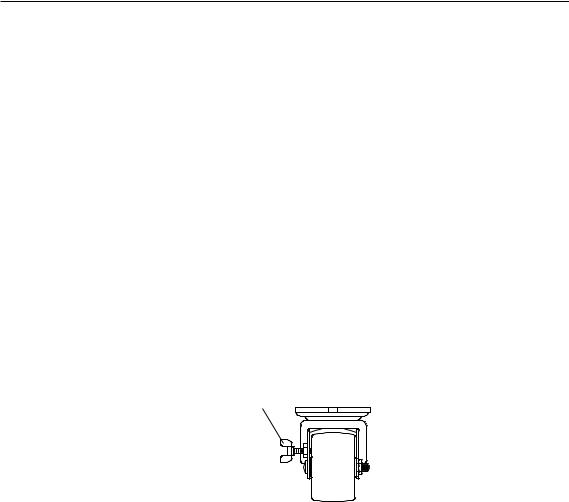
3. On both racks, lock each caster wheel by tightening the thumbscrew on the caster.
Thumbscrew
4.Adjust the leveling feet on the I/O rack by doing the following:
a.Loosen the locking nut by turning the locking nut counter-clockwise (away from the bottom of the rack).
4 S80, S85 Installation Guide
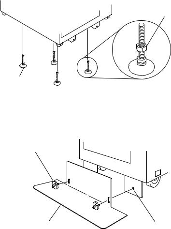
b.Adjust the height of the leveling feet by rotating the leveling feet either upward or downward according to the level of the surface on which the rack is placed. Repeat this for the remaining leveling feet as needed.
c.When the rack is leveled, tighten the locking nuts on all of the leveling feet.
Locking Nut
Leveling Feet (4)
5.Align the slots in the stabilizer with the mounting holes in the bottom front of the I/O rack.
6.Ensure that the base of the stabilizer rests firmly on the floor.
7.Install the two mounting screws and hand-tighten.
Mounting Screw
Stabilizer |
Mounting Hole |
8.Use the crank supplied with the system unit to alternately tighten the mounting screws until they are firmly seated.
Chapter 1. System Installation Procedure 5

Mounting Screw
9.Hang the crank and tightening rod on the bracket near the bottom of the right wall inside the back of the rack.
Tightening
Rod
Crank
10.Install the rear stabilizer on the I/O rack, as follows:
a.Loosen the lower screws on the stabilizer assembly.
b.Slide the stabilizer assembly onto the bottom of the rack.
c.Install screws at the top of the stabilizer assembly and tighten.
d.Tighten the lower screws on the stabilizer assembly.
6 S80, S85 Installation Guide

e.Adjust the bolts to the floor to ensure that the stabilizer is level and does not move.
11. If head protectors are installed, remove them from diskette drives.
Step 6A. Attach the I/O Rack to a Concrete Floor
Perform this step if the I/O rack is to be attached to a concrete floor or a concrete floor beneath a raised floor.
Notes:
1.Ensure that the primary I/O rack (the primary I/O rack contains the service processor) is positioned on the right side of the system rack when viewed from the front. A clearance of 10 cm (4 inches) between the racks is required to allow access to the I/O rack door.
2.If you are attaching the I/O rack:
Chapter 1. System Installation Procedure 7
vTo a concrete floor, continue with ªAttaching the I/O Rack to a Concrete Floorº.
vTo a concrete floor below a raised floor, go to ªAttaching the I/O Rack to a Concrete Floor Beneath a Raised Floorº on page 10.
If you are not attaching the I/O rack to a concrete floor, continue with ªStep 7. Attach the Front Electrical Outletº on page 18.
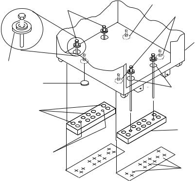
Attaching the I/O Rack to a Concrete Floor
The customer is responsible for attaching the rack-mounting plates to the concrete floor.
Note: Because of the length of the four rack-mounting bolts, the drawer located in the bottom position of the rack must be removed to install the four rack-mounting bolts to the floor.
1.Mark the floor around the edge of each leveling foot.
2.Place the two mounting plates in the approximate mounting locations under the rack.
3.To align the rack over the mounting plates, do the following:
a.Place the four rack-mounting bolts through the mounting holes at the bottom of the rack.
b.Position the mounting plates under the four rack-mounting bolts so that the mounting bolts are centered directly over the tapped holes. Insert the rack-mounting bolts three or four rotations into the tapped holes.
4.Mark the floor around the edge of both mounting plates.
5.Remove the mounting bolts from the threaded holes.
6.To access the holes in the mounting plates, raise the four leveling feet, and then move the rack away from the mounting plates.
7.Mark the floor at the center of each hole in the mounting plates (including the tapped holes).
8.Remove the two mounting plates from the marked locations.
9.At the marked location of the tapped mounting holes, drill two holes approximately 1 inch to allow clearance for the ends of the two rack-mounting bolts. The ends of the rack-mounting bolts may protrude past the thickness of the mounting plate.
Note: A minimum of three anchor bolts for each mounting plate must be used to mount the plates to the concrete floor. Because some of the drilled holes may be aligned with concrete reinforcement rods below the surface of the concrete floor, some of the drilled holes may not be usable. For each mounting plate, select at least three usable holes, two that are on opposite sides and opposite ends of each other, and one hole at the center.
8 S80, S85 Installation Guide
Rack Mounting Bolts
Mounting Holes
Front of
Rack
Mounting Holes
Holes for Anchor Bolts (10)
Mounting Plate (2)
Location Marks (Drill One of
Tapped Holes for TheseTwo Marks) Rack Mounting Bolts
Location Marks (Drill Location Marks (Drill One One of These Six Marks) of These Two Marks)
10.Drill one hole in each group of anchor bolt location marks as indicated on the marked floor.
11.Using at least three anchor bolts for each mounting plate, mount the two mounting plates to the concrete floor.
12.Using the location marks for leveling feet as a guide, reposition the rack over the mounting plates.
13.Place the four rack-mounting bolts through the four metal washers, and then through the four plastic isolator washers. The flat side of the plastic isolator washer must be facing upward.
14.To further align the rack over the mounting plates, do the following:
a.Place the four rack-mounting bolts (with the four plastic isolator washers) through the mounting holes in the bottom of the rack.
b.Align the four mounting bolts to the location of the four tapped holes in the two mounting plates.
c.Insert the rack-mounting bolts three to four rotations into the tapped holes.
Note: The bottom of the four leveling feet must be positioned over the four plastic isolator pads when the rack is leveled.
If you are installing an ac-powered rack, do not use the four plastic isolator pads.
Chapter 1. System Installation Procedure 9
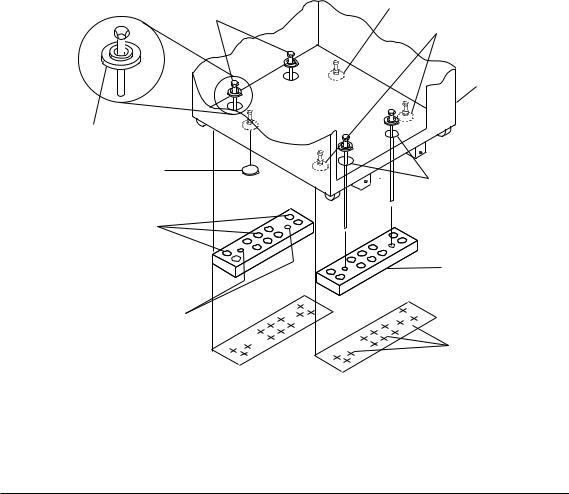
15.Place the four plastic isolator pads under the four leveling feet, and then level the rack using the four adjustable leveling feet.
16.Tighten the locking nuts on the leveling feet.
Leveling Foot (4)
Rack-Mounting
Bolts
Rack-Mounting
Bolts
Front of
Rack
Plastic Isolator
Washer (4)
Plastic Isolator
Pad (4)
Mounting
Holes
Holes for
Anchor Bolts
Mounting
Plates (2)
Tapped Holes for
Rack Mounting Bolts
Location
Marks
17.Tighten the four rack-mounting bolts into the two mounting plates.
18.If a drawer was removed from the bottom position of the rack, reinstall it.
Attaching the I/O Rack to a Concrete Floor Beneath a Raised Floor
The customer is responsible for obtaining the services of a mechanical contractor to attach the rack-mounting plates on the raised floor with hardware that goes through the raised floor into the concrete floor below the raised floor. The mechanical contractor should determine that the raised floor support and the hardware used to attach the rack mounting plates is sufficient to meet the customer's requirements for the installation.
Note: Because of the length of the four rack-mounting bolts, the drawer located in the bottom position of the rack must be removed to install the four rack-mounting bolts to the floor.
1. Mark the floor around the edge of each leveling foot.
10 S80, S85 Installation Guide
2.Place the two mounting plates in the approximate mounting locations under the rack.
3.To align the rack over the mounting plates, do the following:
a.Place the four rack-mounting bolts through the mounting holes at the bottom of the rack.
b.Position the mounting plates under the four rack-mounting bolts so that the mounting bolts are centered directly over the tapped holes. Insert the rack-mounting bolts three or four rotations into the tapped holes.
4.Mark the raised-floor panel around the edge of both mounting plates.
5.Remove the mounting bolts from the threaded holes.
6.To access the holes in the mounting plates, raise the four leveling feet, and then move the rack away from the mounting plates.
7.Mark the raised-floor panel at the center of each hole in the mounting plates (including the tapped holes).
8.Remove the two mounting plates from the marked locations.
Chapter 1. System Installation Procedure 11
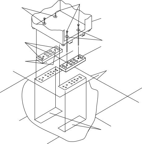
Mounting Holes
Holes for Anchor Bolts (10)
Tapped Holes for Rack Mounting Bolts
Rack Mounting Bolts
Front of
Rack
Mounting Holes
Mounting Plate (2)
Raised
Floor Panels
Projection of Mounting
Plates onto Concrete Floor
9.At the marked location of the tapped mounting holes, drill two holes approximately 1 inch to allow clearance for the ends of the two rack-mounting bolts. The ends of the rack-mounting bolts may protrude past the thickness of the mounting plate.
Note: A minimum of three anchor bolts for each mounting plate must be used to mount the plates to the raised-floor panel. For each mounting plate, select at least three usable holes, two that are on opposite sides and opposite ends of each other, and one hole at the center.
10.Drill one hole in each group of anchor bolt location marks as indicated on the marked raised floor panel.
11.Ensure that the marks for the holes for the anchor bolts in the concrete floor align with the holes in the raised floor panel.
12.Drill the holes in the concrete floor for the anchor bolts.
12 S80, S85 Installation Guide
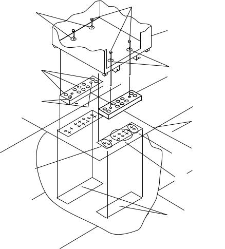
Mounting Holes
Holes for Anchor Bolts (10)
Tapped Holes for Rack Mounting Bolts
Location Marks
(Drill One of
These Two Marks)
Rack Mounting Bolts
Front of
Rack
Mounting Holes
Mounting Plate (2)
Raised
Floor Panels
Location Marks
(Drill One of
These Two Marks)
Location Marks
(Drill One of
These Six Marks)
Projection of Mounting
Plates onto Concrete Floor
13.Place the two mounting plates on the locations indicated on the marked raised-floor panel.
14.Using at least three anchor bolts for each mounting plate, mount the two mounting plates through the raised-floor panel to the concrete floor.
15.Using the location marks for leveling feet as a guide, reposition the rack over the mounting plates.
16.Place the four rack-mounting bolts through the four metal washers, and then through the four plastic isolator washers. The flat side of the plastic isolator washer must be facing upward.
17.To further align the rack over the mounting plates, do the following:
a.Place the four rack-mounting bolts (with the four plastic isolator washers) through the mounting holes in the bottom of the rack.
b.Align the four mounting bolts to the location of the four tapped holes in the two mounting plates.
Chapter 1. System Installation Procedure 13
c.Insert the rack-mounting bolts three to four rotations into the tapped holes.
Note: The bottoms of the four leveling feet must be positioned over the four plastic isolator pads when the rack is leveled. If you are installing an AC powered rack, do not use the four plastic isolator pads.
18.Place the four plastic isolator pads under the four leveling feet, and then level the rack using the four adjustable leveling feet.
19.Tighten the locking nuts on the leveling feet.
Leveling Foot (4)
Rack-Mounting
Bolts
Rack-Mounting
Bolts
Front of
Rack
Plastic Isolator
Washer (4)
Plastic Isolator
Pad (4)
Mounting
Holes
Holes for
Anchor Bolts
Mounting
Plates (2)
Tapped Holes for
Rack Mounting Bolts
Location
Marks
20.Tighten the four rack-mounting bolts into the two mounting plates.
21.If you are attaching an electrical outlet and mounting plate, skip to ªStep 7. Attach the Front Electrical Outletº on page 18 or ªStep 8. Attach the Rear Electrical Outletº on page 22 as appropriate, then return here.
22.If a drawer was removed from the bottom position of the rack, reinstall it.
Step 6B. Attach the System Rack to a Concrete Floor
Perform this step if the system rack is to be attached to a concrete floor or a concrete floor beneath a raised floor.
14 S80, S85 Installation Guide
Notes:
1.Ensure that the primary I/O rack (the primary I/O rack contains the service processor) is positioned on the right side of the system rack when viewed from the front. A clearance of 10 cm (4 inches) between the racks is required to allow access to the I/O rack door.
2.If you are attaching the system rack:
v To a concrete floor, continue with ªAttaching the System Rack to a Concrete Floorº.
vTo a concrete floor below a raised floor, go to ªAttaching the System Rack to a Concrete Floor Beneath a Raised Floorº on page 16.
If you are not attaching the system rack to a concrete floor, continue with ªStep 7. Attach the Front Electrical Outletº on page 18.
Attaching the System Rack to a Concrete Floor
The customer is responsible for attaching the rack-mounting plates to the concrete floor.
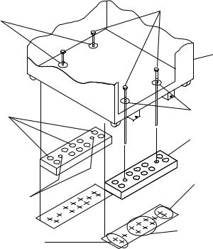
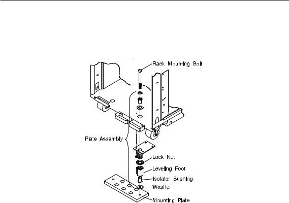
1.Install the 4 plate assemblies with the leveling feet, bushings and washers. Make sure that the leveling feet are backed off the floor level to allow space for the mounting plates.
2.Place the mounting plates, front and rear, (note that they are different) in the approximate mounting position under the system rack.
3.To align the system rack over the mounting plate, do the following:
a.Place the four rack-mounting bolts through the plate assembly holes at the bottom of the rack (install the bushings and washers to ensure bolt positioning).
Chapter 1. System Installation Procedure 15

b.Position the mounting plates under the four rack-mounting bolts so that the mounting bolts are centered directly over the tapped holes.
c.Insert the rack-mounting bolts three or four rotations into the tapped holes.
4.Mark the floor around the edge of the mounting plates.
5.Remove the mounting bolts from the threaded holes.
6.Move the rack away from the mounting plates.
7.Mark the floor at the center of each hole in the mounting plate (including tapped holes).
8.Remove the mounting plates from the marked locations.
9.At the marked location of the tapped mounting holes, drill two holes approximately 1 inch to allow clearance for the ends of the two rack-mounting bolts. The ends of the rack-mounting bolts may protrude past the thickness of the mounting plate.
Note: A minimum of three anchor bolts for each mounting plate must be used to mount the plates to the concrete floor. Because some of the drilled holes may be aligned with concrete reinforcement rods below the surface of the concrete floor, some of the drilled holes may not be usable. For each mounting plate, select at least three usable holes, two that are on opposite sides and opposite ends of each other, and one hole at the center.
Drill one hole in each group of anchor bolt location marks as indicated on the marked floor.
10.Using at least three bolts for each mounting plate, mount the mounting plates to the concrete floor.
11.Reposition the system rack over the mounting plates.
12.Place the four rack-mounting bolts through the plate assemblies with the D-washer positioned so that the straight side of the washer is facing inward toward the system rack.
13.Place the isolator bushing inside the leveling foot with a washer between the isolator bushing and the floor plate.
14.Insert the rack-mounting bolts three or four rotations into the tapped holes.
15.Turn the leveling foot of the plate assembly down until it contacts the mounting plate, and then level the rack using the four leveling feet.
16.Lock the leveling feet by tightening the lock nut.
17.Tighten the four rack-mounting bolts into the mounting plates.
Attaching the System Rack to a Concrete Floor Beneath a Raised Floor
The customer is responsible for obtaining the services of a mechanical contractor to attach the rack-mounting plates on the raised floor with hardware that goes through the raised floor into the concrete floor below the raised floor. The mechanical contractor should determine that the raised floor support and the hardware used to attach the rack mounting plates is sufficient to meet the customer's requirements for the installation.
16 S80, S85 Installation Guide
Loading...