


Pavilion dv5000
Table of contents
 Loading...
Maintenance and Service
Guide
HP Pavilion dv5100 Notebook PC
Document Part Number: 405500-002
June 2006
This guide is a troubleshooting reference used for maintaining
and servicing the computer. It provides comprehensive
information on identifying computer features, components, and
spare parts; troubleshooting computer problems; and performing
computer disassembly procedures.

© Copyright 2006 Hewlett-Packard Development Company, L.P.
Microsoft and Windows are U.S. registered trademarks of Microsoft
Corporation. Intel and Pentium are trademarks or registered trademarks of
Intel Corporation or its subsidiaries in the United States and other
countries. Bluetooth is a trademark owned by its proprietor and used by
Hewlett-Packard Company under license. SD Logo is a trademark of its
proprietor.
The information contained herein is subject to change without notice. The
only warranties for HP products and services are set forth in the express
warranty statements accompanying such products and services. Nothing
herein should be construed as constituting an additional warranty. HP shall
not be liable for technical or editorial errors or omissions contained herein.
Maintenance and Service Guide
HP Pavilion dv5100 Notebook PC
Second Edition: June 2006
First Edition: February 2006
Document Part Number: 405500-002

Maintenance and Service Guide iii
Contents
1 Product Description
1.1 Features . . . . . . . . . . . . . . . . . . . . . . . . . . . . . . . . . . . 1–2
1.2 Resetting the Computer. . . . . . . . . . . . . . . . . . . . . . . 1–4
1.3 Power Management. . . . . . . . . . . . . . . . . . . . . . . . . . 1–5
1.4 External Components . . . . . . . . . . . . . . . . . . . . . . . . 1–6
1.5 Design Overview. . . . . . . . . . . . . . . . . . . . . . . . . . . 1–20
2 Troubleshooting
2.1 Computer Setup. . . . . . . . . . . . . . . . . . . . . . . . . . . . . 2–1
Using Computer Setup . . . . . . . . . . . . . . . . . . . . . . . 2–1
Selecting from the File Menu . . . . . . . . . . . . . . . . . . 2–2
Selecting from the Security Menu . . . . . . . . . . . . . . 2–3
Selecting from the Diagnostics Menu. . . . . . . . . . . . 2–4
Selecting from the System Configuration Menu. . . . 2–5
2.2 Troubleshooting Flowcharts . . . . . . . . . . . . . . . . . . . 2–6

iv Maintenance and Service Guide
Contents
3 Illustrated Parts Catalog
3.1 Serial Number Location . . . . . . . . . . . . . . . . . . . . . . 3–1
3.2 Computer Major Components. . . . . . . . . . . . . . . . . . 3–2
3.3 Display Assembly Subcomponents. . . . . . . . . . . . . 3–16
3.4 Plastics Kit . . . . . . . . . . . . . . . . . . . . . . . . . . . . . . . 3–18
3.5 Cable Kit . . . . . . . . . . . . . . . . . . . . . . . . . . . . . . . . . 3–19
3.6 Mass Storage Devices . . . . . . . . . . . . . . . . . . . . . . . 3–20
3.7 Miscellaneous (Not Illustrated). . . . . . . . . . . . . . . . 3–22
3.8 Sequential Part Number Listing . . . . . . . . . . . . . . . 3–24
4 Removal and Replacement Preliminaries
4.1 Tools Required . . . . . . . . . . . . . . . . . . . . . . . . . . . . . 4–1
4.2 Service Considerations . . . . . . . . . . . . . . . . . . . . . . . 4–2
Plastic Parts . . . . . . . . . . . . . . . . . . . . . . . . . . . . . . . . 4–2
Cables and Connectors . . . . . . . . . . . . . . . . . . . . . . . 4–2
4.3 Preventing Damage to Removable Drives . . . . . . . . 4–3
4.4 Preventing Electrostatic Damage . . . . . . . . . . . . . . . 4–4
4.5 Packaging and Transporting Precautions . . . . . . . . . 4–5
4.6 Workstation Precautions . . . . . . . . . . . . . . . . . . . . . . 4–6
4.7 Grounding Equipment and Methods . . . . . . . . . . . . . 4–7

Contents
Maintenance and Service Guide v
5 Removal and Replacement Procedures
5.1 Serial Number . . . . . . . . . . . . . . . . . . . . . . . . . . . . . . 5–1
5.2 Disassembly Sequence Chart . . . . . . . . . . . . . . . . . . 5–2
5.3 Preparing the Computer for Disassembly . . . . . . . . . 5–4
5.4 Hard Drive. . . . . . . . . . . . . . . . . . . . . . . . . . . . . . . . . 5–6
5.5 Computer Feet. . . . . . . . . . . . . . . . . . . . . . . . . . . . . 5–10
5.6 Memory Module . . . . . . . . . . . . . . . . . . . . . . . . . . . 5–11
5.7 Mini Card Module. . . . . . . . . . . . . . . . . . . . . . . . . . 5–13
5.8 RTC Battery . . . . . . . . . . . . . . . . . . . . . . . . . . . . . . 5–16
5.9 Optical Drive. . . . . . . . . . . . . . . . . . . . . . . . . . . . . . 5–17
5.10 Switch Cover. . . . . . . . . . . . . . . . . . . . . . . . . . . . . 5–20
5.11 Keyboard Frame . . . . . . . . . . . . . . . . . . . . . . . . . . 5–22
5.12 LED Board . . . . . . . . . . . . . . . . . . . . . . . . . . . . . . 5–26
5.13 Keyboard . . . . . . . . . . . . . . . . . . . . . . . . . . . . . . . . 5–28
5.14 Display Assembly . . . . . . . . . . . . . . . . . . . . . . . . . 5–30
5.15 Top Cover . . . . . . . . . . . . . . . . . . . . . . . . . . . . . . . 5–41
5.16 Bluetooth Module . . . . . . . . . . . . . . . . . . . . . . . . . 5–48
5.17 System Board . . . . . . . . . . . . . . . . . . . . . . . . . . . . 5–50
5.18 USB/Audio Board . . . . . . . . . . . . . . . . . . . . . . . . . 5–58
5.19 Fan/Heat Sink Assembly. . . . . . . . . . . . . . . . . . . . 5–60
5.20 Processor . . . . . . . . . . . . . . . . . . . . . . . . . . . . . . . . 5–65
5.21 Speakers . . . . . . . . . . . . . . . . . . . . . . . . . . . . . . . . 5–67
5.22 PC Card Assembly . . . . . . . . . . . . . . . . . . . . . . . . 5–69
5.23 ExpressCard Assembly . . . . . . . . . . . . . . . . . . . . . 5–72

vi Maintenance and Service Guide
Contents
6 Specifications
A Screw Listing
B Software Update and Recovery
C Display Component Recycling
D Connector Pin Assignments
E Power Cord Set Requirements
Index
Maintenance and Service Guide 1–1
1
Product Description
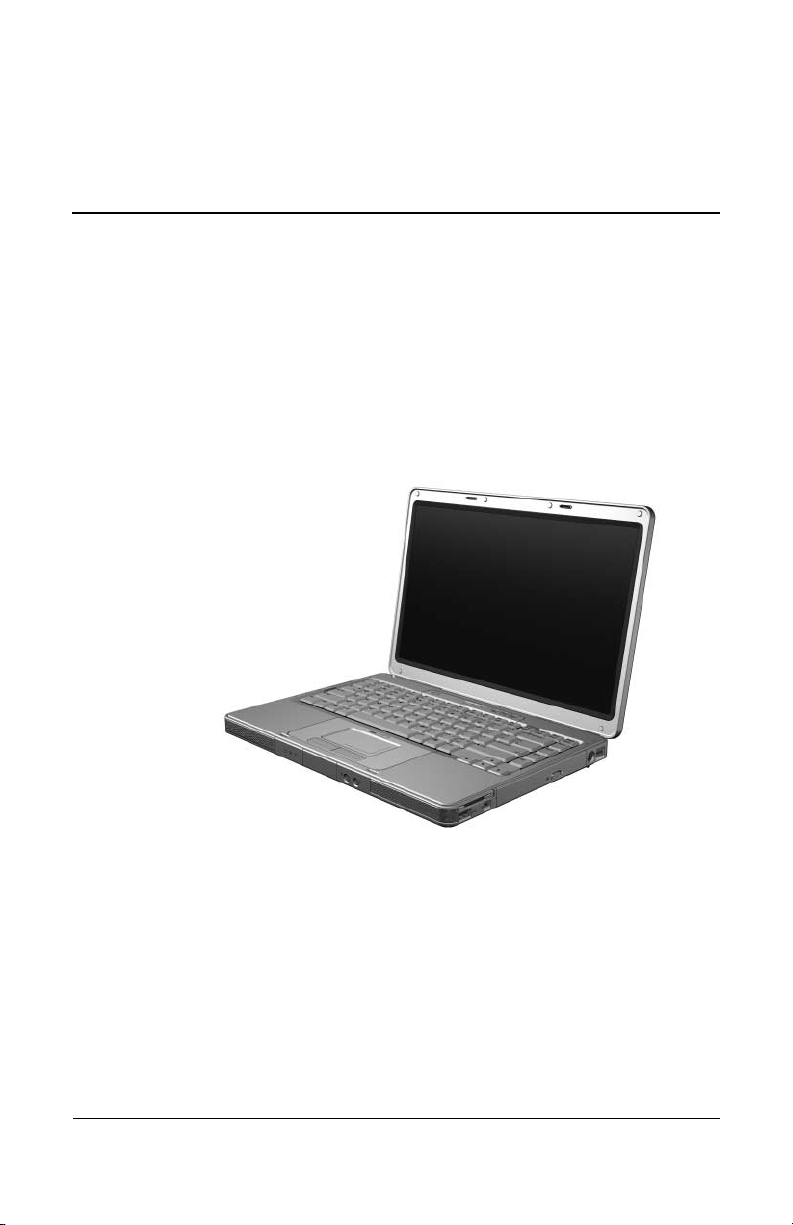
The HP Pavilion dv5100 Notebook PC offers advanced
modularity, Intel® Pentium® M processors, and extensive
multimedia support.
HP Pavilion dv5100 Notebook PC

1–2 Maintenance and Service Guide
Product Description
1.1 Features
✎
Numerous references are made throughout this Maintenance and
Service Guide to “full-featured” and “defeatured” computer
models. A model is considered to be full-featured if it has
3 Universal Serial Bus ports and the following components:
■ PC Card slot
■ IEEE 1394 port
■ Digital Media Slot
A model is considered to be defeatured if it has only two
Universal Serial Bus ports and none of the components listed
above.
■ The following processors, varying by computer model:
❏ Intel Pentium M 2.0- or 1.83-GHz
❏ Intel Celeron M 1.60-GHz or 410 1.46-GHz
❏ Intel Core Duo T2600 (2.16-GHz), T2250 (1.73-GHz),
T2300E (1.66-GHz), or T2050 (1.60-GHz)
❏ Intel Core Solo T1350 1.86-, 1.83-GHz, or 1.66-GHz
■ 15.4-inch, WXGA, TFT (1280 × 800) display with antiglare
or BrightView, varying by computer model
■ 120, 100-, 80-, 60-, or 40-GB high-capacity hard drive,
varying by computer model
■ 256-MB DDR1 synchronous DRAM (SDRAM) at 667 MHz,
expandable to 2.0 GB
■ Microsoft® Windows® XP Home Edition or Windows XP
Professional, varying by computer model
■ Full-size Windows keyboard with embedded numeric keypad
■ TouchPad pointing device, including dedicated vertical scroll
region

Product Description
Maintenance and Service Guide 1–3
■ Integrated 10Base-T/100Base-TX Ethernet local area
network (LAN) network interface card (NIC) with RJ-45 jack
■ Integrated high-speed 56K modem with RJ-11 jack
■ Integrated wireless support for Mini Card IEEE 802.11a/b/g
WLAN device
■ Support for one Type I or Type II PC Card slot, with support
for both 32-bit (CardBus) and 16-bit PC Cards
■ Support for ExpressCard slot
■ External 65-watt AC adapter with 3-wire power cord
■ 12- or 6-cell Li-Ion battery
■ Stereo speakers
■ Volume up, volume mute, and volume down buttons
■ Support for the following optical drives:
❏ DVD±RW and CD-RW Super Multi Double-Layer
Combo Drive with LightScribe
❏ DVD±RW and CD-RW Super Multi Double-Layer
Combo Drive
❏ DVD±RW and CD-RW Double-Layer Combo Drive with
LightScribe and Hitachi LG Data Storage
❏ DVD±RW and CD-RW Double-Layer Combo Drive with
LightScribe
❏ DVD/CD-RW Double-Layer Combo Drive with
LightScribe
❏ DVD/CD-RW Combo Drive
❏ DVD-ROM drive

1–4 Maintenance and Service Guide
Product Description
■ Connectors:
❏ Audio-in (microphone)
❏ Audio-out (headphone)
❏ Digital Media Slot (select models only)
❏ Expansion port 2
❏ ExpressCard slot
❏ External monitor
❏ IEEE 1394 (select models only)
❏ PC Card (select models only)
❏ Power
❏ RJ-11 (modem)
❏ RJ-45 (network)
❏ S-Video-out
❏ Universal Serial Bus (USB) v. 2.0 (2 or 3 ports, varying by
computer model)
1.2 Resetting the Computer
If the computer you are servicing has an unknown password,
follow these steps to clear the password. These steps also
clear CMOS:
1. Prepare the computer for disassembly (refer to Section 5.3,
“Preparing the Computer for Disassembly,” for more
information.)
2. Remove the real-time clock (RTC) battery (refer to Section
5.8, “RTC Battery,” for more information.)

Product Description
Maintenance and Service Guide 1–5
3. Wait approximately 5 minutes.
4. Replace the RTC battery and reassemble the computer.
5. Connect AC power to the computer. Do not reinsert any
batteries at this time.
6. Turn on the computer.
All passwords and CMOS settings have been cleared.
1.3 Power Management
The computer comes with power management features that
extend battery operating time and conserve power. The
computer supports the following power management features:
■ Standby
■ Hibernation
■ Setting customization by the user
■ Hotkeys for setting the level of performance
■ Battery calibration
■ Lid switch standby/resume
■ Power button
■ Advanced Configuration and Power Management (ACPM)
compliance

1–6 Maintenance and Service Guide
Product Description
1.4 External Components
The external components on the front of the computer are shown
below and described in Table 1-1.
Front Components

Product Description
Maintenance and Service Guide 1–7
Tabl e 1-1
Front Components
Item Component Function
1Power light ■ On: Computer is turned on.
■ Off: Computer is off or in hibernation.
■ Blinking: Computer is in standby.
2Battery light ■ On: A battery is charging or is close to
full charge capacity.
■ Off: If the computer is plugged into an
external power source, the light is turned
off when all batteries in the computer are
fully charged. If the computer is not
plugged into an external power source,
the light stays off until the battery
reaches a low-battery condition.
■ Blinking: A battery that is the only
available power source has reached a
low-battery condition. When the battery
reaches a critical low-battery condition,
the battery light begins blinking quickly.
3 Drive light On or blinking: The internal hard drive or an
optical drive is being accessed.
4 Speakers Produce stereo sound.
5 Display release latch Opens the computer.
1–8 Maintenance and Service Guide
Product Description
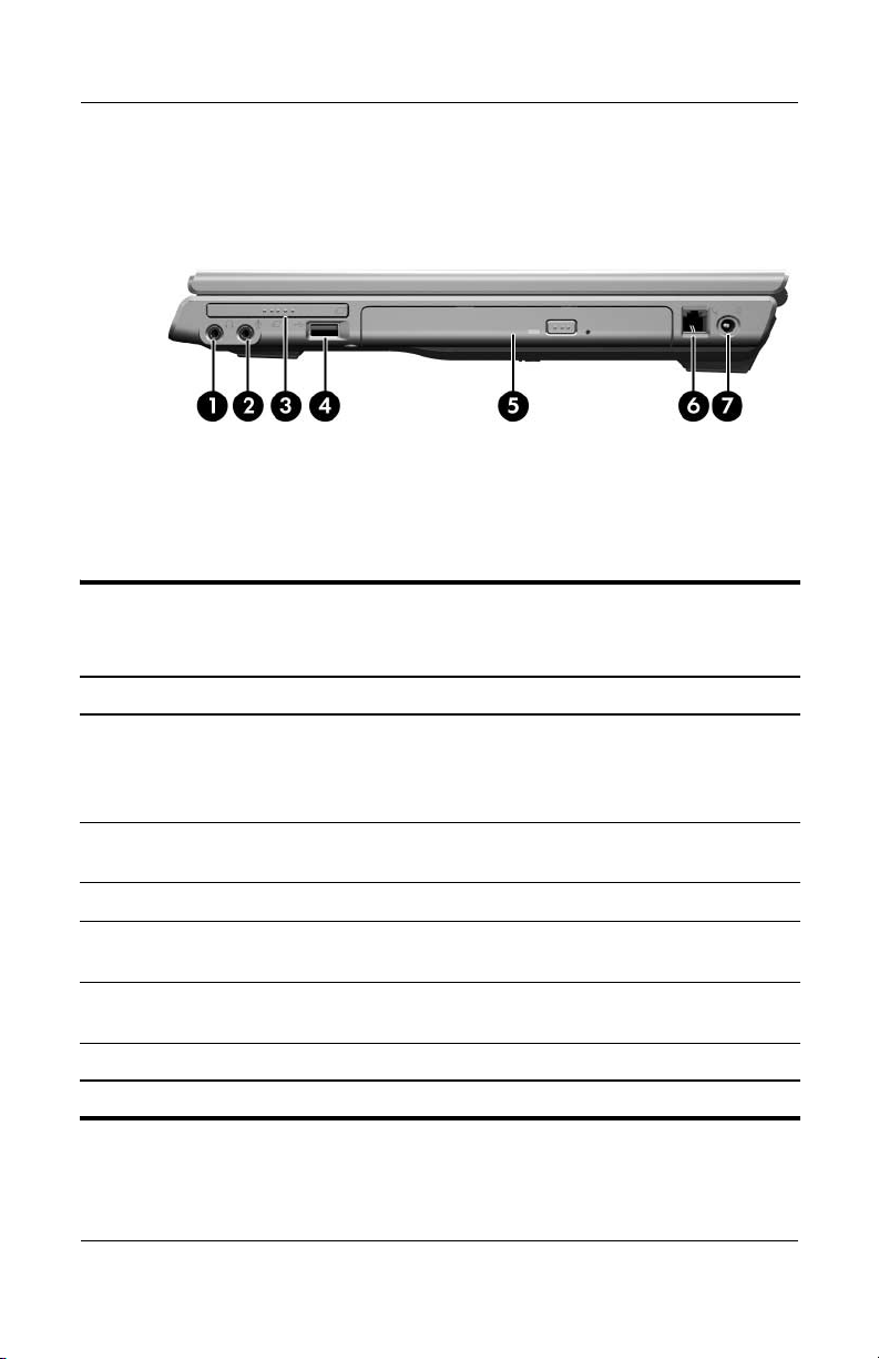
The external components on the right side of the computer are
shown below and described in Table 1-2.
Right-Side Components
Tabl e 1-2
Right-Side Components
Item Component Function
1Audio-out
(headphone) jack
Connects an optional headphone or
powered stereo speakers. Also connects
the audio function of an audio/video device,
such as a television or VCR.
2 Audio-in (microphone)
jack
Connects an optional stereo microphone.
3 ExpressCard slot Supports an optional ExpressCard.
4 USB port
(select models only)
Connects optional USB devices.
5 Optical drive Supports an optical disc, such as a CD or
DVD.
6 RJ-11 (modem) jack Connects a modem cable (not included).
7 Power connector Connects the AC adapter cable.
Product Description
Maintenance and Service Guide 1–9
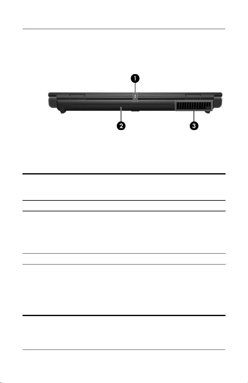
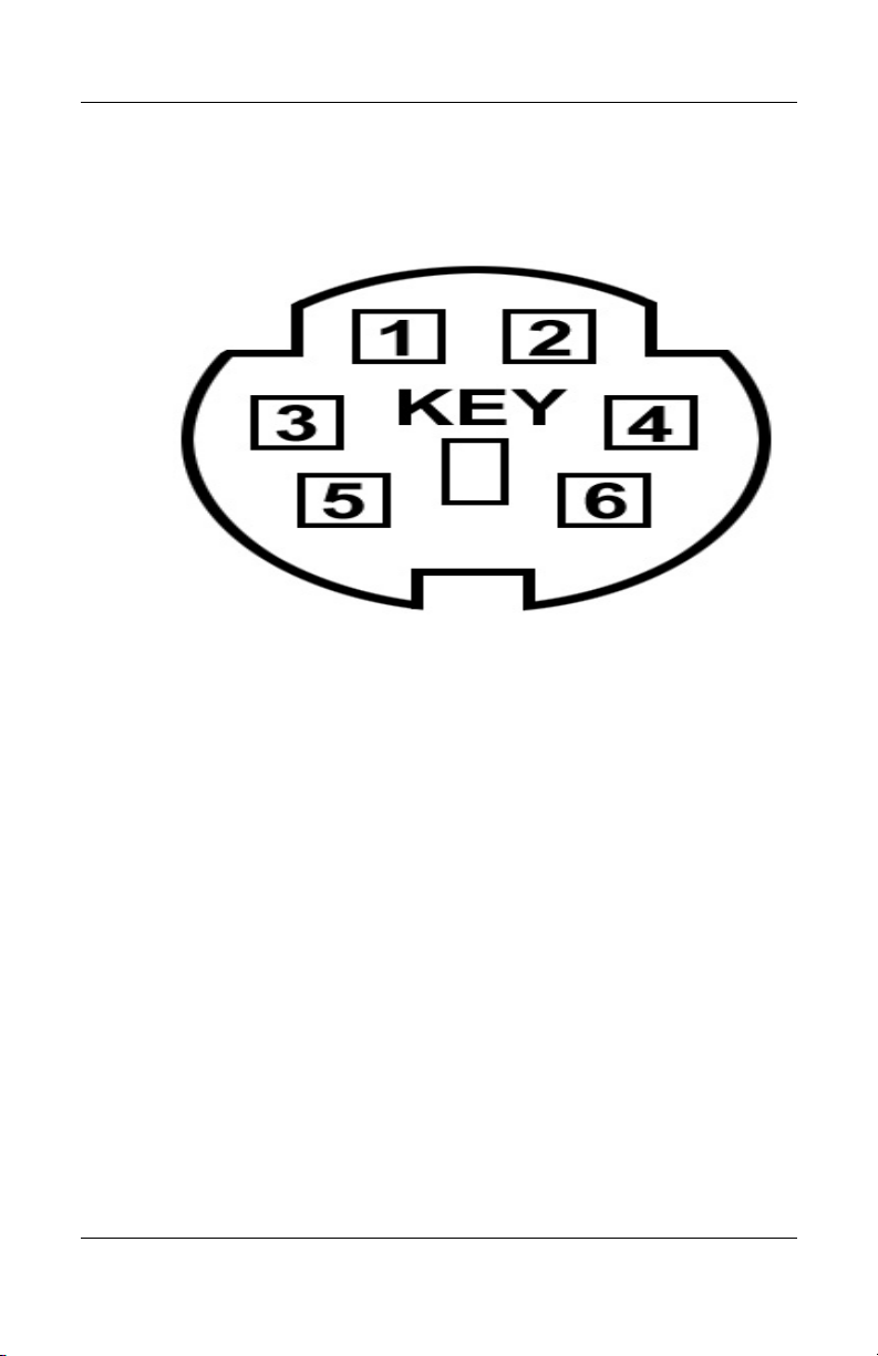
The external components on the rear panel of the computer are
shown below and described in Table 1-3.
Rear Panel Components
Tabl e 1-3
Rear Panel Components
Item Component Function
1 Wireless light On: One or more internal wireless devices
have been turned on.
✎
To establish a wireless connection, a
wireless network must already be set
up.
2 Battery bay Holds a battery.
3 Vent Provides airflow to cool internal
components.
Ä
To prevent overheating, do not
obstruct vents. Do not allow a hard
surface, such as a printer, or a soft
surface, such as pillows or thick rugs
or clothing, to block airflow.
1–10 Maintenance and Service Guide
Product Description
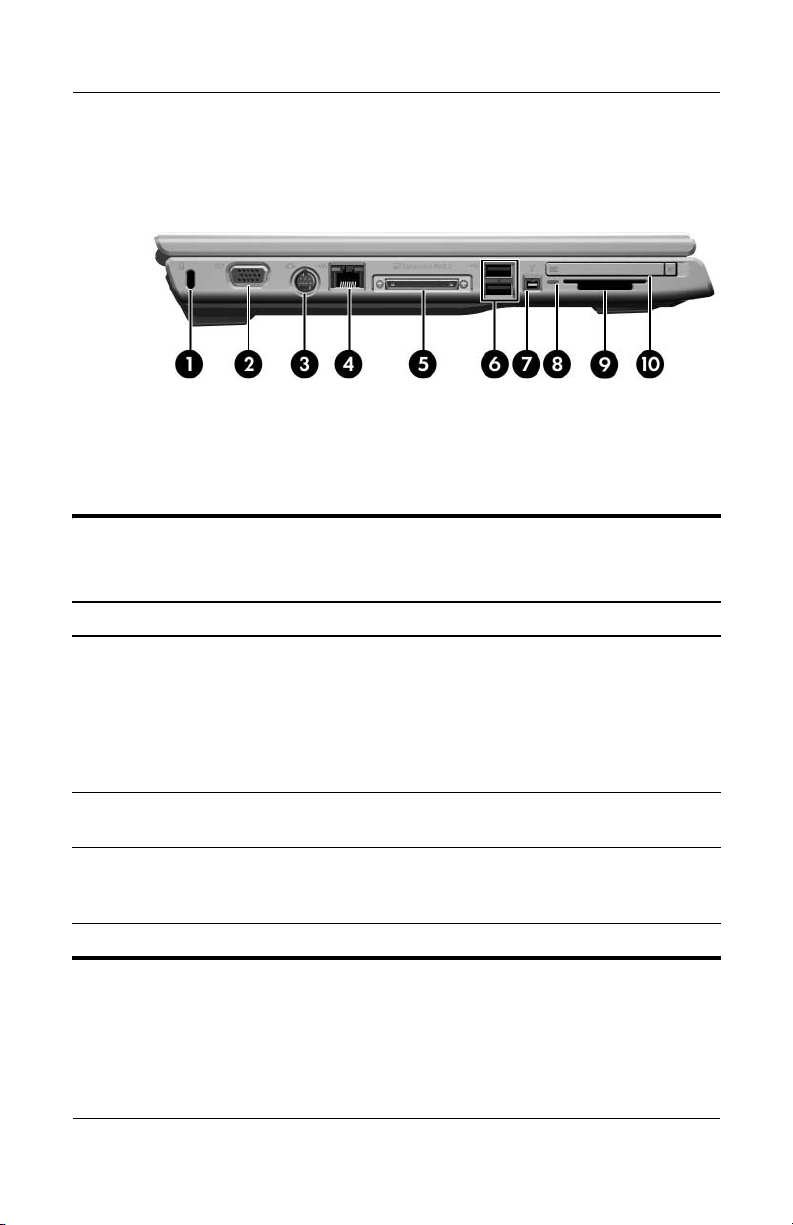
The external components on the left side of the computer are
shown below and described in Table 1-4.
Left-Side Components
Tabl e 1-4
Left-Side Components
Item Component Function
1 Security cable slot Attaches an optional security cable to the
computer.
✎
The security cable is designed to act
as a deterrent, but may not prevent
the product from being mishandled or
stolen.
2 Monitor port Connects an optional VGA monitor or
projector.
3 S-Video-out jack Connects the video function of an optional
S-Video device, such as a television, VCR,
or video capture card.
4 RJ-45 (network) jack Connects a network cable (not included).

Product Description
Maintenance and Service Guide 1–11
5 Expansion port 2 Connects the computer to an optional
expansion product.
✎
The computer has only one
expansion port. The term
expansion
port 2
describes the type of
expansion port.
6 USB ports (2) Connect optional USB devices.
7 1394 port
(select models only))
Connects an optional 1394a device such as
a scanner, a digital camera, or a digital
camcorder.
8 Digital Media Slot light
(select models only)
On: An optional digital card is being
accessed.
9 Digital Media Slot
(select models only)
Supports the following optional digital
cards: Secure Digital (SD) Memory Card,
SD I/O Card, Memory Stick, Memory Stick
Pro, MultiMediaCard, xD-Picture Card, and
SmartMedia.
10 PC Card slot
(select models only)
Supports an optional Type I or Type II
32-bit (CardBus) or 16-bit PC Card.
Tabl e 1-4
Left-Side Components
(Continued)
Item Component Function
1–12 Maintenance and Service Guide
Product Description
The standard keyboard components of the computer are shown
below and described in Table 1-5.
Standard Keyboard Components

Product Description
Maintenance and Service Guide 1–13
Table 1-5
Standard Keyboard Components
Item Component Function
1 f1 to f12 keys (12) Perform system and application tasks.
When combined with fn, function keys
perform additional tasks as hotkeys.
2 caps lock key Enables caps lock and turns on the
caps lock light.
3 fn
key Combines with other keys to perform
system tasks as hotkeys. For example,
pressing fn+f7 decreases screen
brightness.
4 Windows logo key Displays the Microsoft Windows Start
menu.
5Windows
applications key
Displays a shortcut menu for items
beneath the pointer.
6 Arrow keys Move the cursor around the screen.
7 Numeric keypad keys
(15)
Can be used like the keys on an external
numeric keypad.
8 num lock key Enables numeric lock, turns on the
embedded numeric keypad, and turns
on the num lock light.
1–14 Maintenance and Service Guide
Product Description
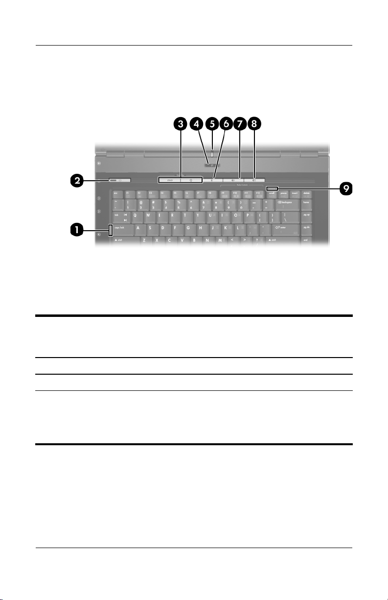
The computer top components are shown below and described in
Table 1-6.
Top Components
Table 1-6
Top Components
Item Component Function
1 Caps lock light On: Caps lock is enabled.
2Power light ■ On: The computer is on.
■ Blinking: The computer is in standby.
■ Off: The computer is off or in
hibernation.

Product Description
Maintenance and Service Guide 1–15
2 Power button When the computer is
■ Off, press to turn on the computer.
■ On, press to enter hibernation.
■ In standby, briefly press to exit standby.
■ In hibernation, briefly press to exit
hibernation.
If the computer has stopped responding
and Microsoft® Windows® shutdown
procedures cannot be used, press and
hold the power button for at least
5 seconds to turn off the computer.
3 QuickLaunch buttons Launch default multimedia, digital imaging,
or music applications.
4 Wireless button Turns the wireless functionality on or off,
but does not create a wireless connection.
✎
To establish a wireless connection,
a wireless network must already be
set up.
5 Wireless light On: One or more internal wireless devices
have been turned on.
✎
To establish a wireless connection,
a wireless network must already be
set up.
6 Volume down button Decreases speaker volume.
7 Volume mute button Mutes or restores speaker volume.
8 Volume up button Increases speaker volume.
9 Num lock light On: Num lock is enabled.
Table 1-6
Top Components
(Continued)
Item Component Function
1–16 Maintenance and Service Guide
Product Description
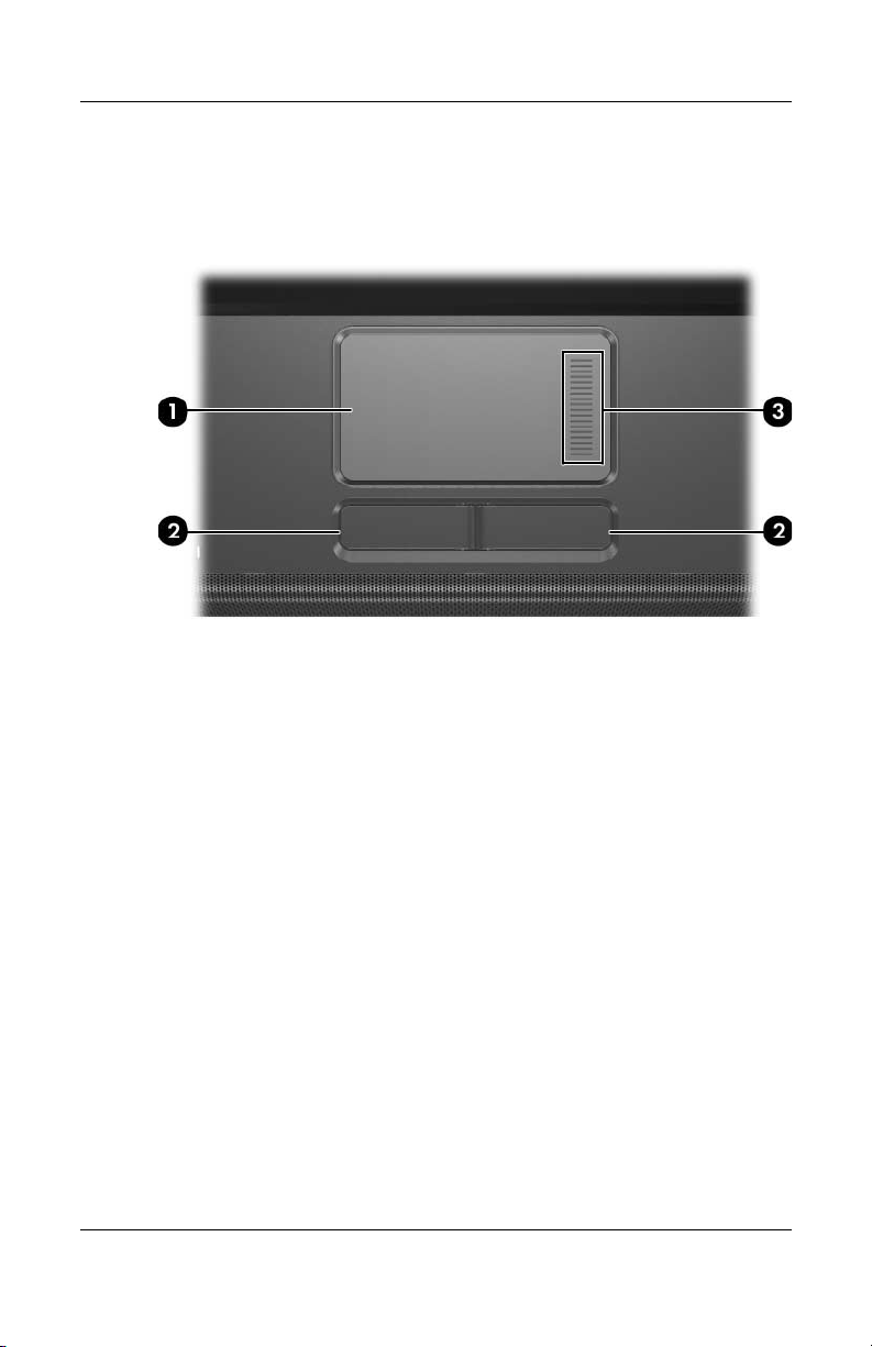
The computer TouchPad components are shown below and
described in Table 1-7.
TouchPad Components

Product Description
Maintenance and Service Guide 1–17
Table 1-7
TouchPad Components
Item Component Function
1 TouchPad Moves the pointer and selects or activates
items on the screen. Can be set to perform
other mouse functions, such as scrolling,
selecting, and double-clicking.
2 Left and right
TouchPad buttons
Function like the left and right buttons on
an external mouse.
3 TouchPad vertical
scroll zone
Scrolls up or down.
1–18 Maintenance and Service Guide
Product Description
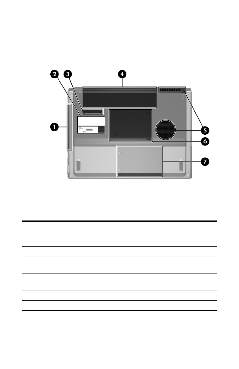
The external components on the bottom of the computer are
shown below and described in Table 1-8.
Bottom Components
Table 1 -8
Bottom Components
Item Component Function
1 Optical drive Supports an optical disc, such as a CD
or DVD.
2 Labels area Contains the serial number and other
information labels.
3 Battery release latch Releases a battery from the battery bay.
4 Battery bay Holds a battery.

Product Description
Maintenance and Service Guide 1–19
5 Vents (2) Provide airflow to cool internal
components.
Ä
To prevent overheating, do not
obstruct vents. Use the computer
only on a hard, flat surface. Do
not allow a another hard surface,
such as an adjoining optional
printer, or a soft surface, such as
pillows or thick rugs or clothing,
to block airflow.
6 Memory/Mini Card module
compartment cover
■ Contains 2 memory module slots that
support replaceable memory
modules. The number of preinstalled
memory modules varies by computer
model.
■ Holds an optional wireless LAN
device (select models only).
Ä
To prevent an unresponsive
system and the display of a
warning message, install only a
Mini Card device authorized for
use in your computer by the
governmental agency that
regulates wireless devices in
your country. If you install an
unauthorized device and then
receive a warning message,
remove the device to restore
computer functionality. Then
contact Customer Care.
7 Hard drive bay Holds the hard drive.
Table 1 -8
Bottom Components
(Continued)
Item Component Function

1–20 Maintenance and Service Guide
Product Description
1.5 Design Overview
This section presents a design overview of key parts and features
of the computer. Refer to Chapter 3, “Illustrated Parts Catalog,”
to identify replacement parts, and Chapter 5, “Removal and
Replacement Procedures,” for disassembly steps.
The system board provides the following device connections:
■ Intel Pentium M processors
■ Audio
■ Digital media card
■ Display
■ ExpressCard
■ Hard drive
■ Keyboard
■ Memory module
■ Mini Card module
■ PC Card
■ To uc hP ad
Ä
CAUTION: To properly ventilate the computer, allow at least a 7.6-cm
(3-inch) clearance on the left and right sides of the computer.
The computer uses an electric fan for ventilation. The fan is
controlled by a temperature sensor and is designed to turn on
automatically when high temperature conditions exist. These
conditions are affected by high external temperatures, system
power consumption, power management/battery conservation
configurations, battery fast charging, and software. Exhaust air is
displaced through the ventilation grill located on the left side of
the computer.

Maintenance and Service Guide 2–1
2
Troubleshooting
Å
WARNING: Only authorized technicians trained by HP should repair
this equipment. All troubleshooting and repair procedures are detailed
to allow only subassembly-/module-level repair. Because of the
complexity of the individual boards and subassemblies, do not attempt
to make repairs at the component level or modifications to any printed
wiring board. Improper repairs can create a safety hazard. Any
indication of component replacement or printed wiring board
modification may void any warranty or exchange allowances.
2.1 Computer Setup
Computer Setup is a system information and customization utility
that can be used even when the operating system is not working
or will not load. This utility includes settings that are not
available in Windows.
Using Computer Setup
Information and settings in Computer Setup are accessed from
the File, Security, Diagnostics, or System Configuration menus:
1. Turn on or restart the computer. Press
f10 while the
F10 = ROM-Based Setup message is displayed in
the lower-left corner of the screen.
❏ To change the language, use the cursor control keys
to navigate to the System Configuration menu.
❏ To view navigation information, press f1.
❏ To return to the Computer Setup menu, press esc.

2–2 Maintenance and Service Guide
Troubleshooting
2. Select the File, Security, Diagnostics, or
System Configuration menu.
3. To close Computer Setup and restart the computer:
❏ Select File > Save changes and exit, and then press enter.
– or –
❏ Select File > Ignore changes and exit, and then
press
enter.
– or –
❏ Select File > Restore defaults, and then press enter.
4. When you are prompted to confirm your action, press
f10.
Selecting from the File Menu
Table 2 -1
File Menu
Select To Do This
System Information ■ View identification information about the
computer, processor, memory and cache size,
and system ROM.
■ View BIOS revision, keyboard controller
version, and battery pack serial number
information.

Troubleshooting
Maintenance and Service Guide 2–3
Selecting from the Security Menu
Table 2 -2
Security Menu
Select To Do This
Setup Password Enter, change, or delete an Setup password.
Power-On Password Enter, change, or delete a power-on password.
Password Options
(Password options can
be selected only when
a power-on password
has been set.)
Enable/disable
■ Stringent security.
■ Requirement of password on restart.
DriveLock Passwords Enable/disable DriveLock; change a DriveLock
user or master password.
✎
DriveLock Settings are accessible only
when you enter Computer Setup by turning
on (not restarting) the computer.
Smart Card Security Enable/disable smart card power-on support.
✎
A setup password must be established to
use this feature.
TPM Embedded Security Enable/disable
■ Embedded security device state.
■ Power-on authentication support.
■ Automatic DriveLock support.
System IDs Establish
■ Notebook asset tracking number.
■ Notebook ownership tags.
Disk Sanitizer Establish fast, optimum, or custom settings for
disk sanitizing.
*Not applicable to SuperDisk LS-120 drives.

2–4 Maintenance and Service Guide
Troubleshooting
Selecting from the Diagnostics Menu
Table 2 -3
Diagnostics Menu
Select To Do This
HDD Self-Test Options Run a quick comprehensive self test on hard
drives in the system that support the test features.
Memory Check Run a quick comprehensive test on system
memory on the following categories:
■ Walking 0s
■ Walking 1s
■ High Address line testing
■ Alternate Pattern testing
Loading...