

Page 1

hp LaserJet 2300
series printer
service
Page 2

Page 3

hp LaserJet 2300 series printer
service manual _____________
Page 4

© Copyright Hewlett-Packard
Company, 2003
All Rights Reserved.
Reproduction, adaptation, or
translation without prior written
permission is prohibited, except
as allowed under the copyright
laws.
Part number: Q2472-90908
Edition 1, April 2003
Warranty
The information contained in this
document is subject to change
without notice.
Hewlett-Packard makes no
warranty of any kind with respect
to this information. HEWLETTPACKARD SPECIFICALLY
DISCLAIMS THE IMPLIED
WARRANTY OF
MERCHANTABILITY AND
FITNESS FOR A PARTICULAR
PURPOSE.
Hewlett-Packard shall not be
liable for any direct, indirect,
incidental, consequential, or
other damage alleged in
connection with the furnishing or
use of this information.
Trademark credits
Adobe® and PostScript® are
trademarks of Adobe Systems
Incorporated which may be
registered in certain jurisdictions.
®
UNIX
is a registered trademark
of the Open Group.
E
NERGY STAR
registered service mark of the
United States Environmental
Protection Agency.
®
is a U.S.
Hewlett-Packard Company
11311 Chinden Boulevard
Boise, Idaho 83714 U.S.A.
Page 5

Contents
1 Product description
Printer configurations. . . . . . . . . . . . . . . . . . . . . . . . . . . . . . . . . . . . . . . . . . . . . . . . . . . . . . . . . . .16
Printer features . . . . . . . . . . . . . . . . . . . . . . . . . . . . . . . . . . . . . . . . . . . . . . . . . . . . . . . . . . . . . . .17
Identification . . . . . . . . . . . . . . . . . . . . . . . . . . . . . . . . . . . . . . . . . . . . . . . . . . . . . . . . . . . . . . . . .19
Specifications . . . . . . . . . . . . . . . . . . . . . . . . . . . . . . . . . . . . . . . . . . . . . . . . . . . . . . . . . . . . . . . .20
Physical specifications . . . . . . . . . . . . . . . . . . . . . . . . . . . . . . . . . . . . . . . . . . . . . . . . . . . . . .20
Electrical specifications. . . . . . . . . . . . . . . . . . . . . . . . . . . . . . . . . . . . . . . . . . . . . . . . . . . . . .20
Power consumption. . . . . . . . . . . . . . . . . . . . . . . . . . . . . . . . . . . . . . . . . . . . . . . . . . . . . . . . .20
Acoustic emissions . . . . . . . . . . . . . . . . . . . . . . . . . . . . . . . . . . . . . . . . . . . . . . . . . . . . . . . . .21
Operating environment . . . . . . . . . . . . . . . . . . . . . . . . . . . . . . . . . . . . . . . . . . . . . . . . . . . . . .21
Product overview. . . . . . . . . . . . . . . . . . . . . . . . . . . . . . . . . . . . . . . . . . . . . . . . . . . . . . . . . . . . . .22
Safety information . . . . . . . . . . . . . . . . . . . . . . . . . . . . . . . . . . . . . . . . . . . . . . . . . . . . . . . . . . . . .23
Print-cartridge and toner safety. . . . . . . . . . . . . . . . . . . . . . . . . . . . . . . . . . . . . . . . . . . . . . . .23
Laser safety. . . . . . . . . . . . . . . . . . . . . . . . . . . . . . . . . . . . . . . . . . . . . . . . . . . . . . . . . . . . . . .24
Regulatory information . . . . . . . . . . . . . . . . . . . . . . . . . . . . . . . . . . . . . . . . . . . . . . . . . . . . . .24
FCC regulations . . . . . . . . . . . . . . . . . . . . . . . . . . . . . . . . . . . . . . . . . . . . . . . . . . . . . . . . . . .24
Declaration of conformity . . . . . . . . . . . . . . . . . . . . . . . . . . . . . . . . . . . . . . . . . . . . . . . . . . . .24
Environmental product stewardship program . . . . . . . . . . . . . . . . . . . . . . . . . . . . . . . . . . . . . . . .25
Protecting the environment . . . . . . . . . . . . . . . . . . . . . . . . . . . . . . . . . . . . . . . . . . . . . . . . . . .25
Material safety data sheet. . . . . . . . . . . . . . . . . . . . . . . . . . . . . . . . . . . . . . . . . . . . . . . . . . . .26
HP Printing Supplies Environmental Program information . . . . . . . . . . . . . . . . . . . . . . . . . . .26
Service approach. . . . . . . . . . . . . . . . . . . . . . . . . . . . . . . . . . . . . . . . . . . . . . . . . . . . . . . . . . . . . .27
Bench-repair warranty. . . . . . . . . . . . . . . . . . . . . . . . . . . . . . . . . . . . . . . . . . . . . . . . . . . . . . .27
HP Express Exchange . . . . . . . . . . . . . . . . . . . . . . . . . . . . . . . . . . . . . . . . . . . . . . . . . . . . . .27
Information about ordering . . . . . . . . . . . . . . . . . . . . . . . . . . . . . . . . . . . . . . . . . . . . . . . . . . .27
World Wide Web . . . . . . . . . . . . . . . . . . . . . . . . . . . . . . . . . . . . . . . . . . . . . . . . . . . . . . . . . .28
HP service parts-information compact disc. . . . . . . . . . . . . . . . . . . . . . . . . . . . . . . . . . . . . . .28
HP support-assistant compact disc. . . . . . . . . . . . . . . . . . . . . . . . . . . . . . . . . . . . . . . . . . . . .28
Reseller sales and service support. . . . . . . . . . . . . . . . . . . . . . . . . . . . . . . . . . . . . . . . . . . . .28
ENWW
2 Installation
Site requirements . . . . . . . . . . . . . . . . . . . . . . . . . . . . . . . . . . . . . . . . . . . . . . . . . . . . . . . . . . . . .30
Operating environment . . . . . . . . . . . . . . . . . . . . . . . . . . . . . . . . . . . . . . . . . . . . . . . . . . . . . .30
Printer space requirements. . . . . . . . . . . . . . . . . . . . . . . . . . . . . . . . . . . . . . . . . . . . . . . . . . .31
Interface ports . . . . . . . . . . . . . . . . . . . . . . . . . . . . . . . . . . . . . . . . . . . . . . . . . . . . . . . . . . . . . . . .33
Contents 3
Page 6

Media specifications . . . . . . . . . . . . . . . . . . . . . . . . . . . . . . . . . . . . . . . . . . . . . . . . . . . . . . . . . . . 34
General media specifications. . . . . . . . . . . . . . . . . . . . . . . . . . . . . . . . . . . . . . . . . . . . . . . . . 34
Media input options . . . . . . . . . . . . . . . . . . . . . . . . . . . . . . . . . . . . . . . . . . . . . . . . . . . . . . . . 35
Tray 1 media sizes. . . . . . . . . . . . . . . . . . . . . . . . . . . . . . . . . . . . . . . . . . . . . . . . . . . . . . . . . 35
Optional 250-sheet tray (tray 2 or tray 3) paper sizes . . . . . . . . . . . . . . . . . . . . . . . . . . . . . . 36
Optional 500-sheet tray (tray 3) paper sizes . . . . . . . . . . . . . . . . . . . . . . . . . . . . . . . . . . . . . 37
Paper sizes for automatic duplexing . . . . . . . . . . . . . . . . . . . . . . . . . . . . . . . . . . . . . . . . . . . 37
Guidelines for selecting paper . . . . . . . . . . . . . . . . . . . . . . . . . . . . . . . . . . . . . . . . . . . . . . . . 38
Envelope specifications . . . . . . . . . . . . . . . . . . . . . . . . . . . . . . . . . . . . . . . . . . . . . . . . . . . . . 39
Label specifications . . . . . . . . . . . . . . . . . . . . . . . . . . . . . . . . . . . . . . . . . . . . . . . . . . . . . . . . 41
Transparency specifications. . . . . . . . . . . . . . . . . . . . . . . . . . . . . . . . . . . . . . . . . . . . . . . . . . 42
Storing print media. . . . . . . . . . . . . . . . . . . . . . . . . . . . . . . . . . . . . . . . . . . . . . . . . . . . . . . . . 43
Shipping print media . . . . . . . . . . . . . . . . . . . . . . . . . . . . . . . . . . . . . . . . . . . . . . . . . . . . . . . 43
Paper fillers . . . . . . . . . . . . . . . . . . . . . . . . . . . . . . . . . . . . . . . . . . . . . . . . . . . . . . . . . . . . . . 43
Testing media specifications . . . . . . . . . . . . . . . . . . . . . . . . . . . . . . . . . . . . . . . . . . . . . . . . . 44
Tools and suppliers . . . . . . . . . . . . . . . . . . . . . . . . . . . . . . . . . . . . . . . . . . . . . . . . . . . . . . . . 49
3 Operation
Control panel . . . . . . . . . . . . . . . . . . . . . . . . . . . . . . . . . . . . . . . . . . . . . . . . . . . . . . . . . . . . . . . . 52
Control-panel layout. . . . . . . . . . . . . . . . . . . . . . . . . . . . . . . . . . . . . . . . . . . . . . . . . . . . . . . . 52
Changing control-panel settings. . . . . . . . . . . . . . . . . . . . . . . . . . . . . . . . . . . . . . . . . . . . . . . 54
Printing control-panel menus . . . . . . . . . . . . . . . . . . . . . . . . . . . . . . . . . . . . . . . . . . . . . . . . . 54
Control-panel menus—user . . . . . . . . . . . . . . . . . . . . . . . . . . . . . . . . . . . . . . . . . . . . . . . . . . . . . 55
Retrieve job menu . . . . . . . . . . . . . . . . . . . . . . . . . . . . . . . . . . . . . . . . . . . . . . . . . . . . . . . . . 55
Information menu . . . . . . . . . . . . . . . . . . . . . . . . . . . . . . . . . . . . . . . . . . . . . . . . . . . . . . . . . . 56
Paper-handling menu. . . . . . . . . . . . . . . . . . . . . . . . . . . . . . . . . . . . . . . . . . . . . . . . . . . . . . . 57
Configure device menu . . . . . . . . . . . . . . . . . . . . . . . . . . . . . . . . . . . . . . . . . . . . . . . . . . . . . 59
Diagnostics menu. . . . . . . . . . . . . . . . . . . . . . . . . . . . . . . . . . . . . . . . . . . . . . . . . . . . . . . . . . 71
Control-panel menus—service . . . . . . . . . . . . . . . . . . . . . . . . . . . . . . . . . . . . . . . . . . . . . . . . . . . 72
Entering service mode . . . . . . . . . . . . . . . . . . . . . . . . . . . . . . . . . . . . . . . . . . . . . . . . . . . . . . 72
4 Printer maintenance
Periodic inspection of parts . . . . . . . . . . . . . . . . . . . . . . . . . . . . . . . . . . . . . . . . . . . . . . . . . . . . 74
Cleaning the printer . . . . . . . . . . . . . . . . . . . . . . . . . . . . . . . . . . . . . . . . . . . . . . . . . . . . . . . . . . . 75
Cleaning the fuser . . . . . . . . . . . . . . . . . . . . . . . . . . . . . . . . . . . . . . . . . . . . . . . . . . . . . . . . . 76
Cleaning the outside of the printer. . . . . . . . . . . . . . . . . . . . . . . . . . . . . . . . . . . . . . . . . . . . . 76
Managing the print cartridge. . . . . . . . . . . . . . . . . . . . . . . . . . . . . . . . . . . . . . . . . . . . . . . . . . . . . 77
HP print cartridges . . . . . . . . . . . . . . . . . . . . . . . . . . . . . . . . . . . . . . . . . . . . . . . . . . . . . . . . . 77
Non-HP print cartridges . . . . . . . . . . . . . . . . . . . . . . . . . . . . . . . . . . . . . . . . . . . . . . . . . . . . . 77
Print-cartridge authentication . . . . . . . . . . . . . . . . . . . . . . . . . . . . . . . . . . . . . . . . . . . . . . . . . 77
Print-cartridge storage . . . . . . . . . . . . . . . . . . . . . . . . . . . . . . . . . . . . . . . . . . . . . . . . . . . . . . 78
Print-cartridge life expectancy . . . . . . . . . . . . . . . . . . . . . . . . . . . . . . . . . . . . . . . . . . . . . . . . 78
Checking the supply level . . . . . . . . . . . . . . . . . . . . . . . . . . . . . . . . . . . . . . . . . . . . . . . . . . . 79
Cartridge-low and cartridge-out conditions . . . . . . . . . . . . . . . . . . . . . . . . . . . . . . . . . . . . . . 80
Supplies status page . . . . . . . . . . . . . . . . . . . . . . . . . . . . . . . . . . . . . . . . . . . . . . . . . . . . . . . 81
Contents
4 ENWW
Page 7

5 Theory of operation
Introduction . . . . . . . . . . . . . . . . . . . . . . . . . . . . . . . . . . . . . . . . . . . . . . . . . . . . . . . . . . . . . . . . . .84
Basic sequence of operation. . . . . . . . . . . . . . . . . . . . . . . . . . . . . . . . . . . . . . . . . . . . . . . . . .84
Power-on sequence . . . . . . . . . . . . . . . . . . . . . . . . . . . . . . . . . . . . . . . . . . . . . . . . . . . . . . . .85
Engine control system . . . . . . . . . . . . . . . . . . . . . . . . . . . . . . . . . . . . . . . . . . . . . . . . . . . . . . . . . .86
Laser/scanner system . . . . . . . . . . . . . . . . . . . . . . . . . . . . . . . . . . . . . . . . . . . . . . . . . . . . . . . . . .87
Image-formation system . . . . . . . . . . . . . . . . . . . . . . . . . . . . . . . . . . . . . . . . . . . . . . . . . . . . . . . .88
Image-formation process . . . . . . . . . . . . . . . . . . . . . . . . . . . . . . . . . . . . . . . . . . . . . . . . . . . .89
Electrostatic latent-image-formation block . . . . . . . . . . . . . . . . . . . . . . . . . . . . . . . . . . . . . . .90
Developing block . . . . . . . . . . . . . . . . . . . . . . . . . . . . . . . . . . . . . . . . . . . . . . . . . . . . . . . . . .91
Transfer block . . . . . . . . . . . . . . . . . . . . . . . . . . . . . . . . . . . . . . . . . . . . . . . . . . . . . . . . . . . . .92
Fusing block . . . . . . . . . . . . . . . . . . . . . . . . . . . . . . . . . . . . . . . . . . . . . . . . . . . . . . . . . . . . . .93
Drum-cleaning block . . . . . . . . . . . . . . . . . . . . . . . . . . . . . . . . . . . . . . . . . . . . . . . . . . . . . . . .94
Pickup/feed system . . . . . . . . . . . . . . . . . . . . . . . . . . . . . . . . . . . . . . . . . . . . . . . . . . . . . . . . . . . .95
Single-sided printing . . . . . . . . . . . . . . . . . . . . . . . . . . . . . . . . . . . . . . . . . . . . . . . . . . . . . . . .95
Duplex printing . . . . . . . . . . . . . . . . . . . . . . . . . . . . . . . . . . . . . . . . . . . . . . . . . . . . . . . . . . . .95
Delivery . . . . . . . . . . . . . . . . . . . . . . . . . . . . . . . . . . . . . . . . . . . . . . . . . . . . . . . . . . . . . . . . .97
Automatic duplexer . . . . . . . . . . . . . . . . . . . . . . . . . . . . . . . . . . . . . . . . . . . . . . . . . . . . . . . . .98
Formatter system. . . . . . . . . . . . . . . . . . . . . . . . . . . . . . . . . . . . . . . . . . . . . . . . . . . . . . . . . . . . . .99
Formatter hardware. . . . . . . . . . . . . . . . . . . . . . . . . . . . . . . . . . . . . . . . . . . . . . . . . . . . . . . .100
Formatter subsystem . . . . . . . . . . . . . . . . . . . . . . . . . . . . . . . . . . . . . . . . . . . . . . . . . . . . . .101
Sheet feeders . . . . . . . . . . . . . . . . . . . . . . . . . . . . . . . . . . . . . . . . . . . . . . . . . . . . . . . . . . . . . . .103
Media detection . . . . . . . . . . . . . . . . . . . . . . . . . . . . . . . . . . . . . . . . . . . . . . . . . . . . . . . . . . . . . .105
Media-size detection . . . . . . . . . . . . . . . . . . . . . . . . . . . . . . . . . . . . . . . . . . . . . . . . . . . . . . .105
Jam detection . . . . . . . . . . . . . . . . . . . . . . . . . . . . . . . . . . . . . . . . . . . . . . . . . . . . . . . . . . . . . . .106
Pickup sensors . . . . . . . . . . . . . . . . . . . . . . . . . . . . . . . . . . . . . . . . . . . . . . . . . . . . . . . . . . .106
Delivery sensors . . . . . . . . . . . . . . . . . . . . . . . . . . . . . . . . . . . . . . . . . . . . . . . . . . . . . . . . . .107
Reversing sensors . . . . . . . . . . . . . . . . . . . . . . . . . . . . . . . . . . . . . . . . . . . . . . . . . . . . . . . .107
Automatic duplexer sensors . . . . . . . . . . . . . . . . . . . . . . . . . . . . . . . . . . . . . . . . . . . . . . . . .108
Paper-feed sensor. . . . . . . . . . . . . . . . . . . . . . . . . . . . . . . . . . . . . . . . . . . . . . . . . . . . . . . . .108
ContentsENWW
5
Page 8

6 Removal and replacement
Removal and replacement strategies. . . . . . . . . . . . . . . . . . . . . . . . . . . . . . . . . . . . . . . . . . . . . 111
Required tools . . . . . . . . . . . . . . . . . . . . . . . . . . . . . . . . . . . . . . . . . . . . . . . . . . . . . . . . . . . 1 1 1
Before you begin . . . . . . . . . . . . . . . . . . . . . . . . . . . . . . . . . . . . . . . . . . . . . . . . . . . . . . . . . 112
Covers . . . . . . . . . . . . . . . . . . . . . . . . . . . . . . . . . . . . . . . . . . . . . . . . . . . . . . . . . . . . . . . . . . . . 113
I/O cover. . . . . . . . . . . . . . . . . . . . . . . . . . . . . . . . . . . . . . . . . . . . . . . . . . . . . . . . . . . . . . . . 113
Print server. . . . . . . . . . . . . . . . . . . . . . . . . . . . . . . . . . . . . . . . . . . . . . . . . . . . . . . . . . . . . . 114
DIMM cover . . . . . . . . . . . . . . . . . . . . . . . . . . . . . . . . . . . . . . . . . . . . . . . . . . . . . . . . . . . . . 115
Rear cover . . . . . . . . . . . . . . . . . . . . . . . . . . . . . . . . . . . . . . . . . . . . . . . . . . . . . . . . . . . . . . 116
Front cover. . . . . . . . . . . . . . . . . . . . . . . . . . . . . . . . . . . . . . . . . . . . . . . . . . . . . . . . . . . . . . 119
Control panel . . . . . . . . . . . . . . . . . . . . . . . . . . . . . . . . . . . . . . . . . . . . . . . . . . . . . . . . . . . . 120
Top-cover assembly. . . . . . . . . . . . . . . . . . . . . . . . . . . . . . . . . . . . . . . . . . . . . . . . . . . . . . . 121
Left-side cover . . . . . . . . . . . . . . . . . . . . . . . . . . . . . . . . . . . . . . . . . . . . . . . . . . . . . . . . . . . 124
Power switch . . . . . . . . . . . . . . . . . . . . . . . . . . . . . . . . . . . . . . . . . . . . . . . . . . . . . . . . . . . . 125
Tray 1 assembly. . . . . . . . . . . . . . . . . . . . . . . . . . . . . . . . . . . . . . . . . . . . . . . . . . . . . . . . . . 126
Internal assemblies. . . . . . . . . . . . . . . . . . . . . . . . . . . . . . . . . . . . . . . . . . . . . . . . . . . . . . . . . . . 13 0
Tray 1 pickup roller. . . . . . . . . . . . . . . . . . . . . . . . . . . . . . . . . . . . . . . . . . . . . . . . . . . . . . . . 130
Pickup sensor flag . . . . . . . . . . . . . . . . . . . . . . . . . . . . . . . . . . . . . . . . . . . . . . . . . . . . . . . . 132
Tray 1 separation pad . . . . . . . . . . . . . . . . . . . . . . . . . . . . . . . . . . . . . . . . . . . . . . . . . . . . . 133
Tray 2 pickup roller. . . . . . . . . . . . . . . . . . . . . . . . . . . . . . . . . . . . . . . . . . . . . . . . . . . . . . . . 136
Tray 2 and 250-sheet feeder separation pad. . . . . . . . . . . . . . . . . . . . . . . . . . . . . . . . . . . . 139
Fan. . . . . . . . . . . . . . . . . . . . . . . . . . . . . . . . . . . . . . . . . . . . . . . . . . . . . . . . . . . . . . . . . . . . 140
Fuser . . . . . . . . . . . . . . . . . . . . . . . . . . . . . . . . . . . . . . . . . . . . . . . . . . . . . . . . . . . . . . . . . . 141
Laser/scanner . . . . . . . . . . . . . . . . . . . . . . . . . . . . . . . . . . . . . . . . . . . . . . . . . . . . . . . . . . . 143
Laser/scanner plate . . . . . . . . . . . . . . . . . . . . . . . . . . . . . . . . . . . . . . . . . . . . . . . . . . . . . . . 144
E-label reader. . . . . . . . . . . . . . . . . . . . . . . . . . . . . . . . . . . . . . . . . . . . . . . . . . . . . . . . . . . . 145
Formatter . . . . . . . . . . . . . . . . . . . . . . . . . . . . . . . . . . . . . . . . . . . . . . . . . . . . . . . . . . . . . . . 147
Drive assembly. . . . . . . . . . . . . . . . . . . . . . . . . . . . . . . . . . . . . . . . . . . . . . . . . . . . . . . . . . . 148
Main motor. . . . . . . . . . . . . . . . . . . . . . . . . . . . . . . . . . . . . . . . . . . . . . . . . . . . . . . . . . . . . . 151
Flat, flexible cable . . . . . . . . . . . . . . . . . . . . . . . . . . . . . . . . . . . . . . . . . . . . . . . . . . . . . . . . 152
Engine controller PCA . . . . . . . . . . . . . . . . . . . . . . . . . . . . . . . . . . . . . . . . . . . . . . . . . . . . . 153
Solenoid. . . . . . . . . . . . . . . . . . . . . . . . . . . . . . . . . . . . . . . . . . . . . . . . . . . . . . . . . . . . . . . . 158
Access plate. . . . . . . . . . . . . . . . . . . . . . . . . . . . . . . . . . . . . . . . . . . . . . . . . . . . . . . . . . . . . 159
Power supply . . . . . . . . . . . . . . . . . . . . . . . . . . . . . . . . . . . . . . . . . . . . . . . . . . . . . . . . . . . . 162
Top-output-bin delivery assembly . . . . . . . . . . . . . . . . . . . . . . . . . . . . . . . . . . . . . . . . . . . . 169
Registration-roller assembly. . . . . . . . . . . . . . . . . . . . . . . . . . . . . . . . . . . . . . . . . . . . . . . . . 172
Transfer roller. . . . . . . . . . . . . . . . . . . . . . . . . . . . . . . . . . . . . . . . . . . . . . . . . . . . . . . . . . . . 174
Feed belts . . . . . . . . . . . . . . . . . . . . . . . . . . . . . . . . . . . . . . . . . . . . . . . . . . . . . . . . . . . . . . 175
Trays. . . . . . . . . . . . . . . . . . . . . . . . . . . . . . . . . . . . . . . . . . . . . . . . . . . . . . . . . . . . . . . . . . . . . . 176
250-sheet feeder and 500-sheet feeder pickup roller . . . . . . . . . . . . . . . . . . . . . . . . . . . . . 176
500-sheet feeder separation pad. . . . . . . . . . . . . . . . . . . . . . . . . . . . . . . . . . . . . . . . . . . . . 178
Contents
6 ENWW
Page 9

7 Troubleshooting
Troubleshooting process . . . . . . . . . . . . . . . . . . . . . . . . . . . . . . . . . . . . . . . . . . . . . . . . . . . . . .180
Preliminary operating checks . . . . . . . . . . . . . . . . . . . . . . . . . . . . . . . . . . . . . . . . . . . . . . . .180
Basic fault isolation . . . . . . . . . . . . . . . . . . . . . . . . . . . . . . . . . . . . . . . . . . . . . . . . . . . . . . . .180
Troubleshooting process flow . . . . . . . . . . . . . . . . . . . . . . . . . . . . . . . . . . . . . . . . . . . . . . . .182
Power-on . . . . . . . . . . . . . . . . . . . . . . . . . . . . . . . . . . . . . . . . . . . . . . . . . . . . . . . . . . . . . . . . . . .183
Troubleshooting with control-panel messages . . . . . . . . . . . . . . . . . . . . . . . . . . . . . . . . . . . . . .184
Using the printer online Help system . . . . . . . . . . . . . . . . . . . . . . . . . . . . . . . . . . . . . . . . . .184
Resolving persistent messages . . . . . . . . . . . . . . . . . . . . . . . . . . . . . . . . . . . . . . . . . . . . . .184
Troubleshooting the control-panel display . . . . . . . . . . . . . . . . . . . . . . . . . . . . . . . . . . . . . .185
Interpreting control-panel messages. . . . . . . . . . . . . . . . . . . . . . . . . . . . . . . . . . . . . . . . . . .186
Media-handling problems . . . . . . . . . . . . . . . . . . . . . . . . . . . . . . . . . . . . . . . . . . . . . . . . . . . . . .199
Printing a configuration page . . . . . . . . . . . . . . . . . . . . . . . . . . . . . . . . . . . . . . . . . . . . . . . .199
Printing a Jetdirect configuration page . . . . . . . . . . . . . . . . . . . . . . . . . . . . . . . . . . . . . . . . .200
Printing a usage page . . . . . . . . . . . . . . . . . . . . . . . . . . . . . . . . . . . . . . . . . . . . . . . . . . . . . .201
Printing a supplies status page . . . . . . . . . . . . . . . . . . . . . . . . . . . . . . . . . . . . . . . . . . . . . . .201
Printing an engine test . . . . . . . . . . . . . . . . . . . . . . . . . . . . . . . . . . . . . . . . . . . . . . . . . . . . .202
Jam troubleshooting . . . . . . . . . . . . . . . . . . . . . . . . . . . . . . . . . . . . . . . . . . . . . . . . . . . . . . .204
Jam causes. . . . . . . . . . . . . . . . . . . . . . . . . . . . . . . . . . . . . . . . . . . . . . . . . . . . . . . . . . . . . .205
Typical jam locations. . . . . . . . . . . . . . . . . . . . . . . . . . . . . . . . . . . . . . . . . . . . . . . . . . . . . . .205
Image-formation troubleshooting. . . . . . . . . . . . . . . . . . . . . . . . . . . . . . . . . . . . . . . . . . . . . . . . .210
Check the print cartridge. . . . . . . . . . . . . . . . . . . . . . . . . . . . . . . . . . . . . . . . . . . . . . . . . . . .211
EconoMode . . . . . . . . . . . . . . . . . . . . . . . . . . . . . . . . . . . . . . . . . . . . . . . . . . . . . . . . . . . . .211
Image defects unique to the HP LaserJet 2300 series printers . . . . . . . . . . . . . . . . . . . . . .211
Image-defect tables. . . . . . . . . . . . . . . . . . . . . . . . . . . . . . . . . . . . . . . . . . . . . . . . . . . . . . . .212
Media troubleshooting . . . . . . . . . . . . . . . . . . . . . . . . . . . . . . . . . . . . . . . . . . . . . . . . . . . . . . . . .218
Determine the problem source: print media or printer. . . . . . . . . . . . . . . . . . . . . . . . . . . . . .218
Isolate a paper path . . . . . . . . . . . . . . . . . . . . . . . . . . . . . . . . . . . . . . . . . . . . . . . . . . . . . . .21 8
Isolate a media brand . . . . . . . . . . . . . . . . . . . . . . . . . . . . . . . . . . . . . . . . . . . . . . . . . . . . . .219
Isolate a media type . . . . . . . . . . . . . . . . . . . . . . . . . . . . . . . . . . . . . . . . . . . . . . . . . . . . . . .220
Evaluate media use practices. . . . . . . . . . . . . . . . . . . . . . . . . . . . . . . . . . . . . . . . . . . . . . . .224
Evaluate environmental conditions . . . . . . . . . . . . . . . . . . . . . . . . . . . . . . . . . . . . . . . . . . . .224
Communication troubleshooting . . . . . . . . . . . . . . . . . . . . . . . . . . . . . . . . . . . . . . . . . . . . . . . . .226
Communications check. . . . . . . . . . . . . . . . . . . . . . . . . . . . . . . . . . . . . . . . . . . . . . . . . . . . .226
Test message . . . . . . . . . . . . . . . . . . . . . . . . . . . . . . . . . . . . . . . . . . . . . . . . . . . . . . . . . . . .226
EIO troubleshooting . . . . . . . . . . . . . . . . . . . . . . . . . . . . . . . . . . . . . . . . . . . . . . . . . . . . . . .226
Troubleshooting tools . . . . . . . . . . . . . . . . . . . . . . . . . . . . . . . . . . . . . . . . . . . . . . . . . . . . . . . . .227
Repetitive defect ruler . . . . . . . . . . . . . . . . . . . . . . . . . . . . . . . . . . . . . . . . . . . . . . . . . . . . . .227
Half-self-test functional check. . . . . . . . . . . . . . . . . . . . . . . . . . . . . . . . . . . . . . . . . . . . . . . .228
Performing a self test . . . . . . . . . . . . . . . . . . . . . . . . . . . . . . . . . . . . . . . . . . . . . . . . . . . . . .229
Performing a paper path test. . . . . . . . . . . . . . . . . . . . . . . . . . . . . . . . . . . . . . . . . . . . . . . . .229
Drum-rotation functional check . . . . . . . . . . . . . . . . . . . . . . . . . . . . . . . . . . . . . . . . . . . . . . .229
Resetting the printer . . . . . . . . . . . . . . . . . . . . . . . . . . . . . . . . . . . . . . . . . . . . . . . . . . . . . . .230
Setting the language . . . . . . . . . . . . . . . . . . . . . . . . . . . . . . . . . . . . . . . . . . . . . . . . . . . . . . .230
Reference diagrams . . . . . . . . . . . . . . . . . . . . . . . . . . . . . . . . . . . . . . . . . . . . . . . . . . . . . . . . . .231
ENWW
Contents
7
Page 10

8 Parts and diagrams
Ordering parts and supplies and getting support . . . . . . . . . . . . . . . . . . . . . . . . . . . . . . . . . . . . 242
Parts. . . . . . . . . . . . . . . . . . . . . . . . . . . . . . . . . . . . . . . . . . . . . . . . . . . . . . . . . . . . . . . . . . . 2 4 2
Support. . . . . . . . . . . . . . . . . . . . . . . . . . . . . . . . . . . . . . . . . . . . . . . . . . . . . . . . . . . . . . . . . 242
Consumables, accessories, and supplies . . . . . . . . . . . . . . . . . . . . . . . . . . . . . . . . . . . . . . 243
Common fasteners . . . . . . . . . . . . . . . . . . . . . . . . . . . . . . . . . . . . . . . . . . . . . . . . . . . . . . . . . . . 244
Illustrations and parts lists . . . . . . . . . . . . . . . . . . . . . . . . . . . . . . . . . . . . . . . . . . . . . . . . . . . . . 245
Assembly locations . . . . . . . . . . . . . . . . . . . . . . . . . . . . . . . . . . . . . . . . . . . . . . . . . . . . . . . 245
Covers . . . . . . . . . . . . . . . . . . . . . . . . . . . . . . . . . . . . . . . . . . . . . . . . . . . . . . . . . . . . . . . . . . . . 246
Covers and panels . . . . . . . . . . . . . . . . . . . . . . . . . . . . . . . . . . . . . . . . . . . . . . . . . . . . . . . . 246
Top cover assembly. . . . . . . . . . . . . . . . . . . . . . . . . . . . . . . . . . . . . . . . . . . . . . . . . . . . . . . 248
Internal components. . . . . . . . . . . . . . . . . . . . . . . . . . . . . . . . . . . . . . . . . . . . . . . . . . . . . . . . . . 250
Internal components (1 of 4) . . . . . . . . . . . . . . . . . . . . . . . . . . . . . . . . . . . . . . . . . . . . . . . . 250
Internal components (2 of 4) . . . . . . . . . . . . . . . . . . . . . . . . . . . . . . . . . . . . . . . . . . . . . . . . 252
Internal components (3 of 4) . . . . . . . . . . . . . . . . . . . . . . . . . . . . . . . . . . . . . . . . . . . . . . . . 254
Internal components (4 of 4) . . . . . . . . . . . . . . . . . . . . . . . . . . . . . . . . . . . . . . . . . . . . . . . . 256
Power-supply assembly . . . . . . . . . . . . . . . . . . . . . . . . . . . . . . . . . . . . . . . . . . . . . . . . . . . . 258
Pickup assembly . . . . . . . . . . . . . . . . . . . . . . . . . . . . . . . . . . . . . . . . . . . . . . . . . . . . . . . . . 260
Engine controller . . . . . . . . . . . . . . . . . . . . . . . . . . . . . . . . . . . . . . . . . . . . . . . . . . . . . . . . . 262
PCA locations. . . . . . . . . . . . . . . . . . . . . . . . . . . . . . . . . . . . . . . . . . . . . . . . . . . . . . . . . . . . 263
Trays. . . . . . . . . . . . . . . . . . . . . . . . . . . . . . . . . . . . . . . . . . . . . . . . . . . . . . . . . . . . . . . . . . . . . . 264
250-sheet feeder . . . . . . . . . . . . . . . . . . . . . . . . . . . . . . . . . . . . . . . . . . . . . . . . . . . . . . . . . 264
500-sheet feeder . . . . . . . . . . . . . . . . . . . . . . . . . . . . . . . . . . . . . . . . . . . . . . . . . . . . . . . . . 266
Alphabetical parts list . . . . . . . . . . . . . . . . . . . . . . . . . . . . . . . . . . . . . . . . . . . . . . . . . . . . . . . . . 268
Numerical parts list. . . . . . . . . . . . . . . . . . . . . . . . . . . . . . . . . . . . . . . . . . . . . . . . . . . . . . . . . . . 273
Contents
8 ENWW
Page 11

Figures
Figure 1. Locations of identification labels. . . . . . . . . . . . . . . . . . . . . . . . . . . . . . . . . . . . . . .19
Figure 2. Sample identification label . . . . . . . . . . . . . . . . . . . . . . . . . . . . . . . . . . . . . . . . . . .19
Figure 3. Front and right side. . . . . . . . . . . . . . . . . . . . . . . . . . . . . . . . . . . . . . . . . . . . . . . . .22
Figure 4. Back and left side . . . . . . . . . . . . . . . . . . . . . . . . . . . . . . . . . . . . . . . . . . . . . . . . . .22
Figure 5. Top view . . . . . . . . . . . . . . . . . . . . . . . . . . . . . . . . . . . . . . . . . . . . . . . . . . . . . . . . .31
Figure 6. Side view. . . . . . . . . . . . . . . . . . . . . . . . . . . . . . . . . . . . . . . . . . . . . . . . . . . . . . . . .31
Figure 7. Side view (with an optional 250-sheet tray) . . . . . . . . . . . . . . . . . . . . . . . . . . . . . .32
Figure 8. Side view (with an optional 500-sheet tray . . . . . . . . . . . . . . . . . . . . . . . . . . . . . . .32
Figure 9. Interface ports. . . . . . . . . . . . . . . . . . . . . . . . . . . . . . . . . . . . . . . . . . . . . . . . . . . . .33
Figure 10. Correct double side seam. . . . . . . . . . . . . . . . . . . . . . . . . . . . . . . . . . . . . . . . . . . .40
Figure 11. Incorrect double side seam. . . . . . . . . . . . . . . . . . . . . . . . . . . . . . . . . . . . . . . . . . .40
Figure 12. Wet test for long, short, and diagonal grain curl . . . . . . . . . . . . . . . . . . . . . . . . . . .47
Figure 13. Measuring curl . . . . . . . . . . . . . . . . . . . . . . . . . . . . . . . . . . . . . . . . . . . . . . . . . . . .47
Figure 14. Control-panel layout . . . . . . . . . . . . . . . . . . . . . . . . . . . . . . . . . . . . . . . . . . . . . . . .52
Figure 15. Supplies status page. . . . . . . . . . . . . . . . . . . . . . . . . . . . . . . . . . . . . . . . . . . . . . . .81
Figure 16. Engine control system. . . . . . . . . . . . . . . . . . . . . . . . . . . . . . . . . . . . . . . . . . . . . . .86
Figure 17. Laser/scanner system. . . . . . . . . . . . . . . . . . . . . . . . . . . . . . . . . . . . . . . . . . . . . . .87
Figure 18. Image-formation system . . . . . . . . . . . . . . . . . . . . . . . . . . . . . . . . . . . . . . . . . . . . .88
Figure 19. Image-formation system . . . . . . . . . . . . . . . . . . . . . . . . . . . . . . . . . . . . . . . . . . . . .89
Figure 20. Step 1: primary charging. . . . . . . . . . . . . . . . . . . . . . . . . . . . . . . . . . . . . . . . . . . . .90
Figure 21. Step 2: laser-beam exposure . . . . . . . . . . . . . . . . . . . . . . . . . . . . . . . . . . . . . . . . .90
Figure 22. Developing block. . . . . . . . . . . . . . . . . . . . . . . . . . . . . . . . . . . . . . . . . . . . . . . . . . .91
Figure 23. Step 3: developing . . . . . . . . . . . . . . . . . . . . . . . . . . . . . . . . . . . . . . . . . . . . . . . . .91
Figure 24. Step 4: transfer . . . . . . . . . . . . . . . . . . . . . . . . . . . . . . . . . . . . . . . . . . . . . . . . . . . .92
Figure 25. Step 5: separation. . . . . . . . . . . . . . . . . . . . . . . . . . . . . . . . . . . . . . . . . . . . . . . . . .92
Figure 26. Step 6: fusing . . . . . . . . . . . . . . . . . . . . . . . . . . . . . . . . . . . . . . . . . . . . . . . . . . . . .93
Figure 27. Step 7: drum cleaning. . . . . . . . . . . . . . . . . . . . . . . . . . . . . . . . . . . . . . . . . . . . . . .94
Figure 28. Step 8: transfer charging roller cleaning. . . . . . . . . . . . . . . . . . . . . . . . . . . . . . . . .94
Figure 29. Pickup/feed system . . . . . . . . . . . . . . . . . . . . . . . . . . . . . . . . . . . . . . . . . . . . . . . .96
Figure 30. Delivery. . . . . . . . . . . . . . . . . . . . . . . . . . . . . . . . . . . . . . . . . . . . . . . . . . . . . . . . . .97
Figure 31. Automatic duplexer path . . . . . . . . . . . . . . . . . . . . . . . . . . . . . . . . . . . . . . . . . . . . .98
Figure 32. Automatic duplexer feed and delivery. . . . . . . . . . . . . . . . . . . . . . . . . . . . . . . . . . .98
Figure 33. Pickup-feed paper path . . . . . . . . . . . . . . . . . . . . . . . . . . . . . . . . . . . . . . . . . . . .103
Figure 34. Sheet-feeder pickup and feed. . . . . . . . . . . . . . . . . . . . . . . . . . . . . . . . . . . . . . . .104
Figure 35. Media-detection sensors. . . . . . . . . . . . . . . . . . . . . . . . . . . . . . . . . . . . . . . . . . . .105
Figure 36. Removing the print cartridge. . . . . . . . . . . . . . . . . . . . . . . . . . . . . . . . . . . . . . . . .112
Figure 37. Removing tray 2 . . . . . . . . . . . . . . . . . . . . . . . . . . . . . . . . . . . . . . . . . . . . . . . . . .112
Figure 38. Removing the I/O cover . . . . . . . . . . . . . . . . . . . . . . . . . . . . . . . . . . . . . . . . . . . .113
Figure 39. Removing the print server. . . . . . . . . . . . . . . . . . . . . . . . . . . . . . . . . . . . . . . . . . .114
Figure 40. Removing the DIMM cover . . . . . . . . . . . . . . . . . . . . . . . . . . . . . . . . . . . . . . . . . .115
Figure 41. Removing the rear cover (1 of 3) . . . . . . . . . . . . . . . . . . . . . . . . . . . . . . . . . . . . .116
Figure 42. Removing the rear cover (2 of 3) . . . . . . . . . . . . . . . . . . . . . . . . . . . . . . . . . . . . .117
Figure 43. Removing the rear cover (3 of 3) . . . . . . . . . . . . . . . . . . . . . . . . . . . . . . . . . . . . .118
Figure 44. Removing the front cover . . . . . . . . . . . . . . . . . . . . . . . . . . . . . . . . . . . . . . . . . . .119
Figure 45. Removing the control panel . . . . . . . . . . . . . . . . . . . . . . . . . . . . . . . . . . . . . . . . .120
Figure 46. Removing the top-cover assembly (1 of 3). . . . . . . . . . . . . . . . . . . . . . . . . . . . . .121
Figure 47. Removing the top-cover assembly (2 of 3). . . . . . . . . . . . . . . . . . . . . . . . . . . . . .122
Figure 48. Removing the top-cover assembly (3 of 3). . . . . . . . . . . . . . . . . . . . . . . . . . . . . .123
Figure 49. Removing the left-side cover . . . . . . . . . . . . . . . . . . . . . . . . . . . . . . . . . . . . . . . .124
Figure 50. Removing the power switch . . . . . . . . . . . . . . . . . . . . . . . . . . . . . . . . . . . . . . . . .125
Figure 51. Removing the tray 1 assembly (1 of 4). . . . . . . . . . . . . . . . . . . . . . . . . . . . . . . . .126
Figure 52. Removing the tray 1 assembly (2 of 4). . . . . . . . . . . . . . . . . . . . . . . . . . . . . . . . .127
ENWW
Figures 9
Page 12

Figure 53. Removing the tray 1 assembly (3 of 4) . . . . . . . . . . . . . . . . . . . . . . . . . . . . . . . . 128
Figure 54. Removing the tray 1 assembly (4 of 4) . . . . . . . . . . . . . . . . . . . . . . . . . . . . . . . . 129
Figure 55. Removing the tray 1 pickup roller (1 of 2) . . . . . . . . . . . . . . . . . . . . . . . . . . . . . . 130
Figure 56. Removing the tray 1 pickup roller (2 of 2) . . . . . . . . . . . . . . . . . . . . . . . . . . . . . . 131
Figure 57. Removing the pickup sensor flag. . . . . . . . . . . . . . . . . . . . . . . . . . . . . . . . . . . . . 132
Figure 58. Removing the tray 1 separation pad (1 of 3) . . . . . . . . . . . . . . . . . . . . . . . . . . . . 133
Figure 59. Removing the tray 1 separation pad (2 of 3) . . . . . . . . . . . . . . . . . . . . . . . . . . . . 134
Figure 60. Removing the tray 1 separation pad (3 of 3) . . . . . . . . . . . . . . . . . . . . . . . . . . . . 135
Figure 61. Removing the tray 2 pickup roller (1 of 3) . . . . . . . . . . . . . . . . . . . . . . . . . . . . . . 136
Figure 62. Removing the tray 2 pickup roller (2 of 3) . . . . . . . . . . . . . . . . . . . . . . . . . . . . . . 137
Figure 63. Removing the tray 2 pickup roller (3 of 3) . . . . . . . . . . . . . . . . . . . . . . . . . . . . . . 138
Figure 64. Removing the tray 2 and 250-sheet feeder separation pad. . . . . . . . . . . . . . . . . 139
Figure 65. Removing the fan. . . . . . . . . . . . . . . . . . . . . . . . . . . . . . . . . . . . . . . . . . . . . . . . . 140
Figure 66. Removing the fuser (1 of 2) . . . . . . . . . . . . . . . . . . . . . . . . . . . . . . . . . . . . . . . . . 141
Figure 67. Removing the fuser (2 of 2) . . . . . . . . . . . . . . . . . . . . . . . . . . . . . . . . . . . . . . . . . 142
Figure 68. Removing the laser/scanner . . . . . . . . . . . . . . . . . . . . . . . . . . . . . . . . . . . . . . . . 143
Figure 69. Removing the e-label reader (1 of 3). . . . . . . . . . . . . . . . . . . . . . . . . . . . . . . . . . 144
Figure 70. Removing the e-label reader (2 of 3). . . . . . . . . . . . . . . . . . . . . . . . . . . . . . . . . . 145
Figure 71. Removing the e-label reader (3 of 3). . . . . . . . . . . . . . . . . . . . . . . . . . . . . . . . . . 146
Figure 72. Removing the formatter . . . . . . . . . . . . . . . . . . . . . . . . . . . . . . . . . . . . . . . . . . . . 147
Figure 73. Removing the drive assembly (1 of 3) . . . . . . . . . . . . . . . . . . . . . . . . . . . . . . . . . 148
Figure 74. Removing the drive assembly (2 of 3) . . . . . . . . . . . . . . . . . . . . . . . . . . . . . . . . . 149
Figure 75. Removing the drive assembly (3 of 3) . . . . . . . . . . . . . . . . . . . . . . . . . . . . . . . . . 150
Figure 76. Removing the main motor . . . . . . . . . . . . . . . . . . . . . . . . . . . . . . . . . . . . . . . . . . 151
Figure 77. Removing the flat, flexible cable . . . . . . . . . . . . . . . . . . . . . . . . . . . . . . . . . . . . . 152
Figure 78. Removing the engine controller PCA (1 of 5) . . . . . . . . . . . . . . . . . . . . . . . . . . . 153
Figure 79. Removing the engine controller PCA (2 of 5) . . . . . . . . . . . . . . . . . . . . . . . . . . . 154
Figure 80. Removing the engine controller PCA (3 of 5) . . . . . . . . . . . . . . . . . . . . . . . . . . . 155
Figure 81. Removing the engine controller PCA (4 of 5) . . . . . . . . . . . . . . . . . . . . . . . . . . . 156
Figure 82. Removing the engine controller PCA (5 of 5) . . . . . . . . . . . . . . . . . . . . . . . . . . . 157
Figure 83. Removing the solenoid . . . . . . . . . . . . . . . . . . . . . . . . . . . . . . . . . . . . . . . . . . . . 158
Figure 84. Removing the access plate (1 of 3) . . . . . . . . . . . . . . . . . . . . . . . . . . . . . . . . . . . 159
Figure 85. Removing the access plate (2 of 3) . . . . . . . . . . . . . . . . . . . . . . . . . . . . . . . . . . . 160
Figure 86. Removing the access plate (3 of 3) . . . . . . . . . . . . . . . . . . . . . . . . . . . . . . . . . . . 161
Figure 87. Removing the power supply (1 of 6) . . . . . . . . . . . . . . . . . . . . . . . . . . . . . . . . . . 162
Figure 88. Removing the power supply (2 of 6) . . . . . . . . . . . . . . . . . . . . . . . . . . . . . . . . . . 163
Figure 89. Removing the power supply (3 of 6) . . . . . . . . . . . . . . . . . . . . . . . . . . . . . . . . . . 164
Figure 90. Removing the power supply (4 of 6) . . . . . . . . . . . . . . . . . . . . . . . . . . . . . . . . . . 165
Figure 91. Removing the power supply (5 of 6) . . . . . . . . . . . . . . . . . . . . . . . . . . . . . . . . . . 166
Figure 92. Removing the power supply (6 of 6) . . . . . . . . . . . . . . . . . . . . . . . . . . . . . . . . . . 167
Figure 93. Power-supply PCA spring-contacts . . . . . . . . . . . . . . . . . . . . . . . . . . . . . . . . . . . 168
Figure 94. Removing the top-output-bin-delivery assembly (1 of 3) . . . . . . . . . . . . . . . . . . . 169
Figure 95. Removing the top-output-bin delivery assembly (2 of 3) . . . . . . . . . . . . . . . . . . . 170
Figure 96. Removing the top-output-bin delivery assembly (3 of 3) . . . . . . . . . . . . . . . . . . . 171
Figure 97. Removing the registration-roller assembly (1 of 2) . . . . . . . . . . . . . . . . . . . . . . . 172
Figure 98. Removing the registration-roller assembly (2 of 2) . . . . . . . . . . . . . . . . . . . . . . . 173
Figure 99. Removing the transfer roller. . . . . . . . . . . . . . . . . . . . . . . . . . . . . . . . . . . . . . . . . 174
Figure 100. Removing the feed belts . . . . . . . . . . . . . . . . . . . . . . . . . . . . . . . . . . . . . . . . . . . 175
Figure 101. Removing the pickup roller from a 250-sheet or 500-sheet feeder (1 of 2). . . . . 176
Figure 102. Removing the pickup roller from a 250-sheet or 500-sheet feeder (2 of 2). . . . . 177
Figure 103. Removing the 500-sheet feeder separation pad . . . . . . . . . . . . . . . . . . . . . . . . . 178
Figure 104. Troubleshooting process flow . . . . . . . . . . . . . . . . . . . . . . . . . . . . . . . . . . . . . . . 182
Figure 105. Control panel contrast label . . . . . . . . . . . . . . . . . . . . . . . . . . . . . . . . . . . . . . . . . 185
Figure 106. Configuration page. . . . . . . . . . . . . . . . . . . . . . . . . . . . . . . . . . . . . . . . . . . . . . . . 199
Figure 107. Jetdirect configuration page. . . . . . . . . . . . . . . . . . . . . . . . . . . . . . . . . . . . . . . . . 200
Figure 108. Engine test button . . . . . . . . . . . . . . . . . . . . . . . . . . . . . . . . . . . . . . . . . . . . . . . . 202
Figure 109. Engine test page . . . . . . . . . . . . . . . . . . . . . . . . . . . . . . . . . . . . . . . . . . . . . . . . . 203
Figure 110. Image defects examples . . . . . . . . . . . . . . . . . . . . . . . . . . . . . . . . . . . . . . . . . . . 212
Figure 111. Repetitive defect ruler . . . . . . . . . . . . . . . . . . . . . . . . . . . . . . . . . . . . . . . . . . . . . 227
Figures
10 ENWW
Page 13

Figure 112. General printer-component locations . . . . . . . . . . . . . . . . . . . . . . . . . . . . . . . . . .231
Figure 113. Locations of switches . . . . . . . . . . . . . . . . . . . . . . . . . . . . . . . . . . . . . . . . . . . . . .232
Figure 114. Locations of sensors. . . . . . . . . . . . . . . . . . . . . . . . . . . . . . . . . . . . . . . . . . . . . . .233
Figure 115. Locations of solenoid . . . . . . . . . . . . . . . . . . . . . . . . . . . . . . . . . . . . . . . . . . . . . .234
Figure 116. Location of motors and fans . . . . . . . . . . . . . . . . . . . . . . . . . . . . . . . . . . . . . . . . .235
Figure 117. Engine controller PCB. . . . . . . . . . . . . . . . . . . . . . . . . . . . . . . . . . . . . . . . . . . . . .236
Figure 118. Power supply PCB . . . . . . . . . . . . . . . . . . . . . . . . . . . . . . . . . . . . . . . . . . . . . . . .237
Figure 119. General circuit diagram (1 of 2) . . . . . . . . . . . . . . . . . . . . . . . . . . . . . . . . . . . . . .238
Figure 120. General circuit diagram (2 of 2) . . . . . . . . . . . . . . . . . . . . . . . . . . . . . . . . . . . . . .239
Figure 121. General timing chart . . . . . . . . . . . . . . . . . . . . . . . . . . . . . . . . . . . . . . . . . . . . . . .240
Figure 122. Assembly locations . . . . . . . . . . . . . . . . . . . . . . . . . . . . . . . . . . . . . . . . . . . . . . . .245
Figure 123. Covers and panels . . . . . . . . . . . . . . . . . . . . . . . . . . . . . . . . . . . . . . . . . . . . . . . .246
Figure 124. Top cover assembly . . . . . . . . . . . . . . . . . . . . . . . . . . . . . . . . . . . . . . . . . . . . . . .248
Figure 125. Internal components (1 of 4). . . . . . . . . . . . . . . . . . . . . . . . . . . . . . . . . . . . . . . . .250
Figure 126. Internal components (2 of 4). . . . . . . . . . . . . . . . . . . . . . . . . . . . . . . . . . . . . . . . .252
Figure 127. Internal components (3 of 4). . . . . . . . . . . . . . . . . . . . . . . . . . . . . . . . . . . . . . . . .254
Figure 128. Internal components (4 of 4). . . . . . . . . . . . . . . . . . . . . . . . . . . . . . . . . . . . . . . . .256
Figure 129. Power-supply assembly . . . . . . . . . . . . . . . . . . . . . . . . . . . . . . . . . . . . . . . . . . . .258
Figure 130. Pickup assembly. . . . . . . . . . . . . . . . . . . . . . . . . . . . . . . . . . . . . . . . . . . . . . . . . .260
Figure 131. Engine controller. . . . . . . . . . . . . . . . . . . . . . . . . . . . . . . . . . . . . . . . . . . . . . . . . .262
Figure 132. PCA locations . . . . . . . . . . . . . . . . . . . . . . . . . . . . . . . . . . . . . . . . . . . . . . . . . . . .263
Figure 133. 250-sheet feeder. . . . . . . . . . . . . . . . . . . . . . . . . . . . . . . . . . . . . . . . . . . . . . . . . .264
Figure 134. 500-sheet feeder. . . . . . . . . . . . . . . . . . . . . . . . . . . . . . . . . . . . . . . . . . . . . . . . . .266
ENWW Figures
11
Page 14

Figures
12 ENWW
Page 15

Tables
Table 1. Features for each configuration . . . . . . . . . . . . . . . . . . . . . . . . . . . . . . . . . . . . . . .18
Table 2. Physical specifications . . . . . . . . . . . . . . . . . . . . . . . . . . . . . . . . . . . . . . . . . . . . . .20
Table 3. Electrical specifications. . . . . . . . . . . . . . . . . . . . . . . . . . . . . . . . . . . . . . . . . . . . . .20
Table 4. Power specifications1 . . . . . . . . . . . . . . . . . . . . . . . . . . . . . . . . . . . . . . . . . . . . . . .20
Table 5. Acoustic emissions specifications1. . . . . . . . . . . . . . . . . . . . . . . . . . . . . . . . . . . . .21
Table 6. Operating environment specifications. . . . . . . . . . . . . . . . . . . . . . . . . . . . . . . . . . .21
Table 7. Solutions for problem media . . . . . . . . . . . . . . . . . . . . . . . . . . . . . . . . . . . . . . . . . .38
Table 8. Envelope specifications . . . . . . . . . . . . . . . . . . . . . . . . . . . . . . . . . . . . . . . . . . . . .39
Table 9. Retrieve job menu. . . . . . . . . . . . . . . . . . . . . . . . . . . . . . . . . . . . . . . . . . . . . . . . . .55
Table 10. Information menu . . . . . . . . . . . . . . . . . . . . . . . . . . . . . . . . . . . . . . . . . . . . . . . . . .56
Table 11. Paper-handling menu . . . . . . . . . . . . . . . . . . . . . . . . . . . . . . . . . . . . . . . . . . . . . . .57
Table 12. Configure device menu—printing submenu . . . . . . . . . . . . . . . . . . . . . . . . . . . . . .59
Table 13. Configure device menu—print-quality submenu. . . . . . . . . . . . . . . . . . . . . . . . . . .61
Table 14. Configure device menu—system-setup submenu . . . . . . . . . . . . . . . . . . . . . . . . .64
Table 15. Configure device menu—I/O submenu. . . . . . . . . . . . . . . . . . . . . . . . . . . . . . . . . .67
Table 16. Configure device menu—resets submenu . . . . . . . . . . . . . . . . . . . . . . . . . . . . . . .70
Table 17. Diagnostics menu . . . . . . . . . . . . . . . . . . . . . . . . . . . . . . . . . . . . . . . . . . . . . . . . . .71
Table 18. Service menu . . . . . . . . . . . . . . . . . . . . . . . . . . . . . . . . . . . . . . . . . . . . . . . . . . . . .72
Table 19. Basic sequence of operation. . . . . . . . . . . . . . . . . . . . . . . . . . . . . . . . . . . . . . . . . .84
Table 20. Output area jams recommended actions . . . . . . . . . . . . . . . . . . . . . . . . . . . . . . .206
Table 21. Paper access area jams—recommended actions . . . . . . . . . . . . . . . . . . . . . . . .207
Table 22. Input-area jams. . . . . . . . . . . . . . . . . . . . . . . . . . . . . . . . . . . . . . . . . . . . . . . . . . .208
Table 23. Possible causes of frequent jams in the cartridge area . . . . . . . . . . . . . . . . . . . .209
Table 24. Image defects . . . . . . . . . . . . . . . . . . . . . . . . . . . . . . . . . . . . . . . . . . . . . . . . . . . .213
Table 25. Adhesive label construction . . . . . . . . . . . . . . . . . . . . . . . . . . . . . . . . . . . . . . . . .221
Table 26. Envelope construction. . . . . . . . . . . . . . . . . . . . . . . . . . . . . . . . . . . . . . . . . . . . . .222
Table 27. Technical support websites. . . . . . . . . . . . . . . . . . . . . . . . . . . . . . . . . . . . . . . . . .242
Table 28. Consumables, accessories, and supplies. . . . . . . . . . . . . . . . . . . . . . . . . . . . . . .243
Table 29. Common fasteners . . . . . . . . . . . . . . . . . . . . . . . . . . . . . . . . . . . . . . . . . . . . . . . .244
Table 30. Covers and panels . . . . . . . . . . . . . . . . . . . . . . . . . . . . . . . . . . . . . . . . . . . . . . . .247
Table 31. Top cover assembly . . . . . . . . . . . . . . . . . . . . . . . . . . . . . . . . . . . . . . . . . . . . . . .249
Table 32. Internal components (1 of 4). . . . . . . . . . . . . . . . . . . . . . . . . . . . . . . . . . . . . . . . .251
Table 33. Internal components (2 of 4). . . . . . . . . . . . . . . . . . . . . . . . . . . . . . . . . . . . . . . . .253
Table 34. Internal components (3 of 4). . . . . . . . . . . . . . . . . . . . . . . . . . . . . . . . . . . . . . . . .255
Table 35. Internal components (4 of 4). . . . . . . . . . . . . . . . . . . . . . . . . . . . . . . . . . . . . . . . .257
Table 36. Power-supply assembly . . . . . . . . . . . . . . . . . . . . . . . . . . . . . . . . . . . . . . . . . . . .259
Table 37. Pickup assembly. . . . . . . . . . . . . . . . . . . . . . . . . . . . . . . . . . . . . . . . . . . . . . . . . .261
Table 38. Engine controller. . . . . . . . . . . . . . . . . . . . . . . . . . . . . . . . . . . . . . . . . . . . . . . . . .262
Table 39. PCA locations . . . . . . . . . . . . . . . . . . . . . . . . . . . . . . . . . . . . . . . . . . . . . . . . . . . .263
Table 40. 250-sheet feeder. . . . . . . . . . . . . . . . . . . . . . . . . . . . . . . . . . . . . . . . . . . . . . . . . .265
Table 41. 500-sheet feeder. . . . . . . . . . . . . . . . . . . . . . . . . . . . . . . . . . . . . . . . . . . . . . . . . .267
Table 42. Alphabetical parts list . . . . . . . . . . . . . . . . . . . . . . . . . . . . . . . . . . . . . . . . . . . . . .268
Table 43. Numerical parts list . . . . . . . . . . . . . . . . . . . . . . . . . . . . . . . . . . . . . . . . . . . . . . . .273
ENWW
Tables 13
Page 16

Tables
14 ENWW
Page 17

1 Product description
Chapter contents
Printer configurations . . . . . . . . . . . . . . . . . . . . . . . . . . . . . . . . . . . . . . . . . . . 16
Printer features . . . . . . . . . . . . . . . . . . . . . . . . . . . . . . . . . . . . . . . . . . . . . . . . 17
Identification . . . . . . . . . . . . . . . . . . . . . . . . . . . . . . . . . . . . . . . . . . . . . . . . . . 19
Specifications . . . . . . . . . . . . . . . . . . . . . . . . . . . . . . . . . . . . . . . . . . . . . . . . . 20
Physical specifications . . . . . . . . . . . . . . . . . . . . . . . . . . . . . . . . . . . . . . . 20
Electrical specifications. . . . . . . . . . . . . . . . . . . . . . . . . . . . . . . . . . . . . . . 20
Power consumption . . . . . . . . . . . . . . . . . . . . . . . . . . . . . . . . . . . . . . . . . 20
Acoustic emissions . . . . . . . . . . . . . . . . . . . . . . . . . . . . . . . . . . . . . . . . . . 21
Operating environment . . . . . . . . . . . . . . . . . . . . . . . . . . . . . . . . . . . . . . . 21
Product overview. . . . . . . . . . . . . . . . . . . . . . . . . . . . . . . . . . . . . . . . . . . . . . . 22
Safety information . . . . . . . . . . . . . . . . . . . . . . . . . . . . . . . . . . . . . . . . . . . . . . 23
Print-cartridge and toner safety . . . . . . . . . . . . . . . . . . . . . . . . . . . . . . . . 23
Laser safety . . . . . . . . . . . . . . . . . . . . . . . . . . . . . . . . . . . . . . . . . . . . . . . 24
Regulatory information . . . . . . . . . . . . . . . . . . . . . . . . . . . . . . . . . . . . . . . 24
FCC regulations . . . . . . . . . . . . . . . . . . . . . . . . . . . . . . . . . . . . . . . . . . . . 24
Declaration of conformity . . . . . . . . . . . . . . . . . . . . . . . . . . . . . . . . . . . . . 24
Environmental product stewardship program . . . . . . . . . . . . . . . . . . . . . . . . . 25
Protecting the environment. . . . . . . . . . . . . . . . . . . . . . . . . . . . . . . . . . . . 25
Material safety data sheet. . . . . . . . . . . . . . . . . . . . . . . . . . . . . . . . . . . . . 26
HP Printing Supplies Environmental Program information. . . . . . . . . . . . 26
Bench-repair warranty . . . . . . . . . . . . . . . . . . . . . . . . . . . . . . . . . . . . . . . 27
HP Express Exchange . . . . . . . . . . . . . . . . . . . . . . . . . . . . . . . . . . . . . . . 27
Information about ordering . . . . . . . . . . . . . . . . . . . . . . . . . . . . . . . . . . . . 27
World Wide Web. . . . . . . . . . . . . . . . . . . . . . . . . . . . . . . . . . . . . . . . . . . . 28
HP service parts-information compact disc . . . . . . . . . . . . . . . . . . . . . . . 28
HP support-assistant compact disc . . . . . . . . . . . . . . . . . . . . . . . . . . . . . 28
Reseller sales and service support. . . . . . . . . . . . . . . . . . . . . . . . . . . . . . 28
ENWW Chapter 1 Product description 15
Page 18
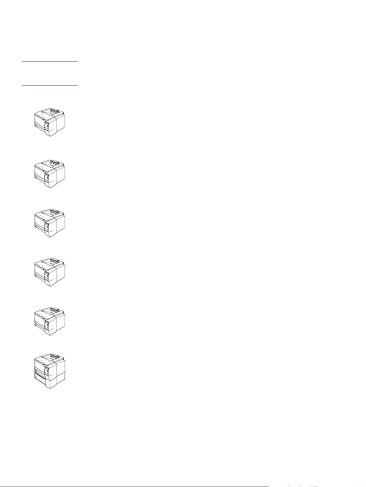
Printer configurations
The HP LaserJet 2300 series printer is available in six configurations.
Note The illustrations in this guide are based on the HP LaserJet 2300 printer model unless otherwise
stated. To find out which HP LaserJet 2300 configuration you have, look at the label on the front
of the printer.
HP LaserJet 2300L
The HP LaserJet 2300L printer prints letter-size paper at speeds up to 20 pages per minute
(ppm) or A4-size paper at up to 19 ppm. It comes with a built-in 250-sheet tra y, a parallel and a
universal serial bus (USB) port, and 32 MB RAM. The printer is ex pandable, and has one
availab le enha nced input/o utput (EIO) slot and t wo dua l inline memo ry module (DIMM) slots f or
adding a network print server card, fonts, and memory.
HP LaserJet 2300
The HP LaserJet 2300 printer is the same as the HP LaserJet 2300L printer, except that it
prints at speeds up to 25 ppm for letter-size paper and 24 ppm for A4-size paper.
HP LaserJet 2300d
The HP LaserJet 2300d printer is the same as the HP LaserJet 2300 printer, except that the
printer comes with 48 MB RAM and automatically duplexes (prints on both sides of paper).
HP LaserJet 2300n
The HP LaserJet 2300n printer is the same as the HP LaserJet 2300 printer, except that it is
designed for network users. It comes with a full-featured HP Jetdirect EIO print server card (for
connecting to a 10/100Base-TX network) and 48 MB RAM.
HP LaserJet 2300dn
The HP LaserJet 2300dn printer is the same as the HP LaserJet 2300n printer, except that the
printer also automatically duplexes (prints on both sides of paper).
HP LaserJet 2300dtn
The HP LaserJet 2300dtn printer is the same as the HP LaserJet 2300dn printer, except that it
has an additional 500-sheet tray.
16 Product description ENWW
Page 19

Printer features
The following table describes the features of the HP LaserJet 2300 series printers.
Fast print
speed
● The HP LaserJet 2300L prints on letter-size paper at speeds up to 20
pages per minute (ppm) or A4-size paper at up to 19 ppm.
● All other models print on letter-size paper at speeds up to 25 ppm or
A4-size paper at up to 24 ppm.
Built-in duplexing ● Automatic two-sided (duplex) printing is a standard feature of the
HP LaserJet 2300d, HP LaserJet 2300dn, and
HP LaserJet 2300dtn printers.
Print cartridge and status
features
● The 6,000-page HP Smart Print Cartridge detects and reports toner
status.
● The no-shake design maximizes toner use.
● The supplies status page provides a toner gauge, page count, and
information about paper sizes that have been used.
Excellent print quality ● FastRes 1200 produces 1200-dpi print quality for fast, high-quality printing
of business text and graphics.
● ProRes 1200 produces 1200-dpi printing for the best quality in line art and
graphic images.
● Adjustable settings optimize print quality.
● The HP Smart Print Cartridge produces crisp, sharp output.
Flexible paper handling
● Use tray 1 (the multipurpose tray) for letterhead, envelopes, labels,
transparencies, custom-sized media, postcards, and heavy paper.
● Use the adjustable 250-sheet tray (tray 2 or tray 3) for standard sizes of
paper.
● Use the 500-sheet tray (tray 3) for letter and A4-size paper.
● Two output bins are available: select either the top output bin or the
rear output bin for the most appropriate output location, depending on
media type.
● A straight-through paper path is available from tray 1 to the
rear output bin.
● Built-in automatic two-sided (duplex) printing is available for the
HP LaserJet 2300d, HP LaserJet 2300dn, and
HP LaserJet 2300dtn printers.
Expandability
● A 250-sheet or 500-sheet tray is av ailab le, so that you do not have to add
paper as often.
● One EIO card slot is available for interface.
● Three DIMM slots are available, two for adding memory and fonts.
Printer languages and
fonts
● Fast printing performance, advanced font and graphics technologies, and
advanced imaging capabilities are benefits of the PCL 6 printer language.
The PCL 6 technology also includes 45 scalab le TrueType™ fonts and
one bitmapped line printer font.
● The other available languages and fonts are HP PCL5e and PostScript
(PS) 3 emulation, which includes 35 built-in PS language fonts.
● The printer automatically determines and switches to the appropriate
language for the print job.
ENWW Chapter 1 Product description 17
®
Page 20

Interface connections and
networking
● The printer includes a bidirectional ECP type-B parallel port
(IEEE-1284 compliant) and a USB port (compatible with 1.1 and 2.0 lowand full-speed certified devices)
● The printer has an EIO slot for HP Jetdirect EIO print servers so that you
can connect quickly and easily.
Enhanced memory and
memory expansion
Energy savings
Economical printing
The table below gives a quick summary of the features for each model.
Table 1. Features for each configuration
● The HP LaserJet 2300 series printers come with either 32 MB or 48 MB
of memory and can be expanded to 288 or 304 MB, respectively, with the
available memory (DIMM) slots. Most documents can be printed by using
the standard amount of printer memory.
● The printer automatically conserves electricity by reducing power
consumption when it is not printing.
● When the PowerSave feature is activated, the printer conser ves energy
when it is not in use.
● As an ENERGY STAR
that this product meets E
● N-up printing saves paper by printing multiple pages on one sheet of
®
partner, Hewlett-Packard Compan y has determined
NERGY STAR
®
guidelines for energy efficiency.
media.
● Automatic two-sided printing with the built-in duplexer saves paper (the
built-in duplexer is included only with the HP LaserJet 2300d,
HP LaserJet 2300dn, and HP LaserJet 2300dtn printers).
● Printing in EconoMode saves toner.
Features
Standard memory
Maximum memory
PostScript 3
HP LaserJet
2300L
32 MB
288 MB
HP LaserJet
2300
32 MB
288 MB
HP LaserJet
2300n
48 MB
304 MB
HP LaserJet
2300d
48 MB
304 MB
HP LaserJet
2300dn
48 MB
304 MB
HP LaserJet
2300dtn
48 MB
304 MB
Standard Standard Standard Standard Standard Standard
emulation
Automatic duplex
N/A N/A N/A Standard Standard Standard
printing
250-sheet feeder Standard Standard Standard Standard Standard Standard
500-sheet feeder Optional Optional Optional Optional Optional Standard
18 Product description ENWW
Page 21
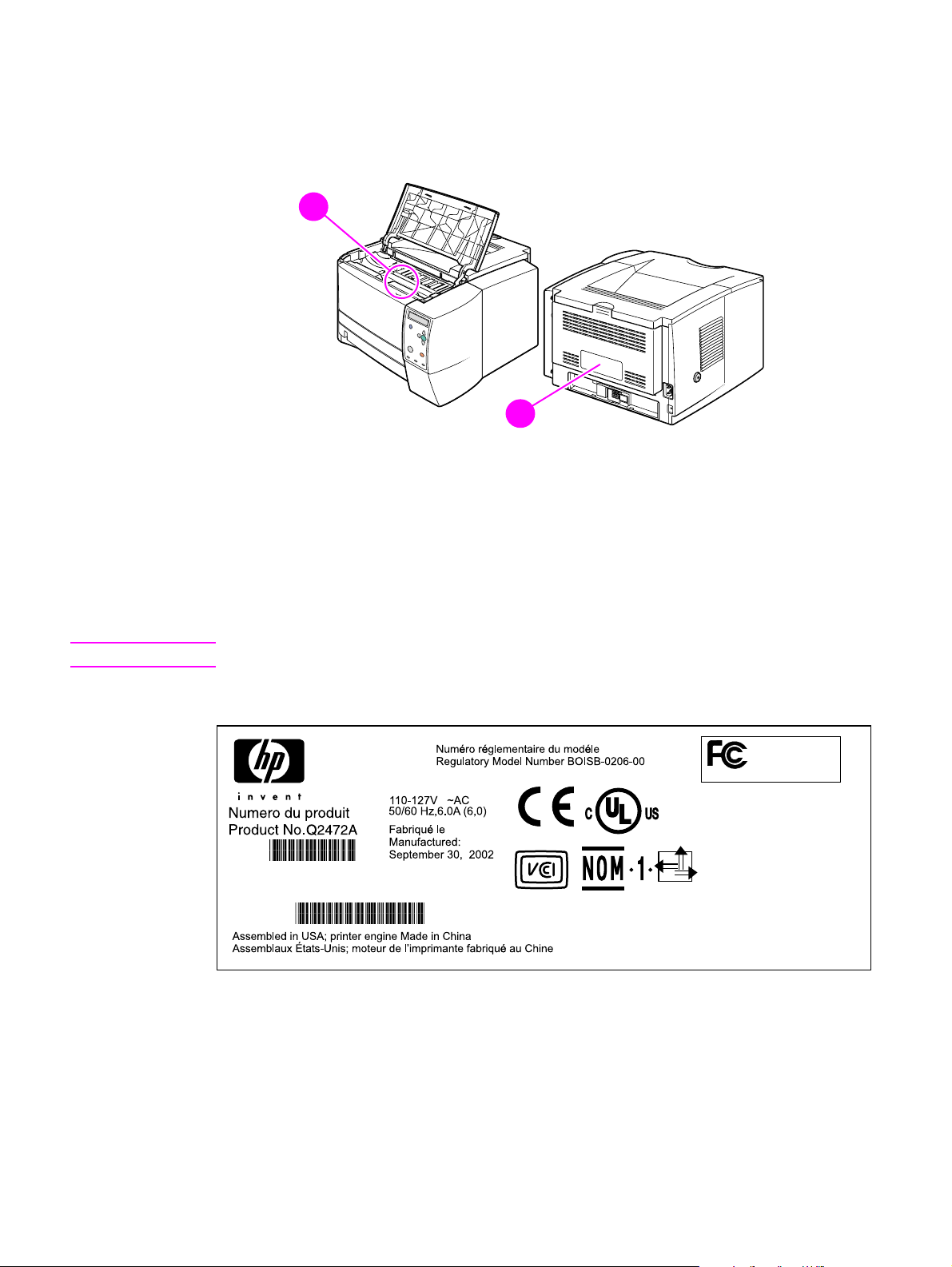
Identification
The model number and printer serial number are listed on ide nt ifica tion la bels lo cate d in side t he
top cover (callout 1) and on the rear output bin (callout 2).
2
1
Figure 1. Locations of identification labels
The model number is alphanumeric. The serial nu mber contains inf ormation about the country of
origin, as well as the revision level and the production code of the printer. An example of a serial
number is USBB123456.
2
2
The identification label on the back of the printer also contains power rating and regulatory
information. See figure 2.
Note The power rating and regulatory information vary by country/region.
Figure 2. Sample identification label
ENWW Chapter 1 Product description 19
Page 22

Specifications
Physical specifications
Table 2. Physical specifications
Height 259.7 mm (10.2 inches) 397.2 mm (15.6 inches)
Width 412.8 mm (16.2 inches) 412.8 mm (16.2 inches)
Depth (body) 450 mm (17.7 inches) 450 mm (17.7 inches)
HP LaserJet 2300L, 2300,
2300n, 2300d, 2300dn
HP LaserJet 2300dtn
(with 500-sheet tray)
Weight (with print
cartridge)
14.3 kg (31.6 lb) 18.9 kg (41.6 lb)
Electrical specifications
WARNING! Po wer requirements are based on the country/region where the printer is sold. Do not convert
operating voltages. This can damage the printer and void the product warranty.
Table 3. Electrical specifications
Electrical
specifications 110-volt models 220-volt models
Power requirements 110 to 127 V (+/- 10%)
50/60 Hz (+/- 3 Hz)
Minimum
recommended circuit
capacity
5.0 amps 2.5 amps
220 to 240 V (+/- 10%)
50/60 Hz (+/- 3 Hz)
Power consumption
Table 4. Power specifications
1
Average power consumption (in watts)
Printing
Product model
HP LaserJet 2300L 394 W — 8.8 W 8.6 W 0 W
HP LaserJet 2300 — 426 W 8.8 W 8.4 W 0 W
HP LaserJet 2300n — 426 W 9.6 W 9.3 W 0 W
HP LaserJet 2300d — 426 W 8.8 W 8.4 W 0 W
HP LaserJet 2300dn — 426 W 9.6 W 9.3 W 0 W
HP LaserJet 2300dtn — 426 W 9.6 W 9.3 W 0 W
1 Values are subject to change. See http://www.hp.com/support/lj2300
2 The PowerSave default activation time is 15 minutes.
(20 ppm)
Printing
(25 ppm) Standby PowerSave2Off
for current information.
20 Product description ENWW
Page 23

Acoustic emissions
Table 5. Acoustic emissions specifications
1
Sound power level Declared per ISO 9296
Printing
(HP LaserJet 2300L at 20 ppm)
Printing
(all other models at 25 ppm)
PowerSave/standby
(all models)
2
L
= 6.6 bels(A)
WAd
L
= 6.7 bels(A)
WAd
Inaudible
Sound pressure level, bystander position Declared per ISO 9296
Printing
(HP LaserJet 2300L at 20 ppm)
Printing
(all other models at 25 ppm)
PowerSave/standby
(all models)
2
Inaudible
L
= 52 dB(A)
pAm
Inaudible
Sound pressure level, operator position Declared per ISO 9296
Printing
(HP LaserJet 2300L at 20 ppm)
Inaudible
Printing
(all other models at 25 ppm)
PowerSave/standby
(all models)
1 Va l u es are subject to change. See http://www.hp.com/support/lj2300
2 In standby, no mechanical parts are moving and therefore no sounds are made.
2
L
= 59 dB(A)
pAm
Inaudible
for current information.
Operating environment
Table 6. Operating environment specifications
Environmental
condition Printing Storage/standby
Temperature
(printer and print
cartridge)
Relative humidity 10 to 80 percent 10 to 90 percent
15 to 32.5 degrees C
(59 to 90.5 degrees F)
-20 to 40 degrees C
(-4 to 104 degrees F)
ENWW Chapter 1 Product description 21
Page 24
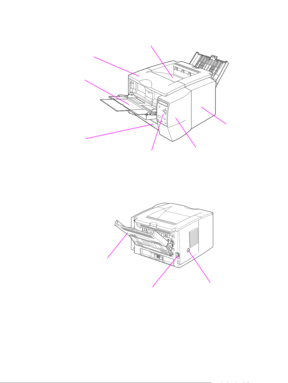
Product overview
Top cover
Tray 1
Tray 2
Top output bin
I/O cover
Figure 3. Front and right side
Rear output bin
Control panel
Power connector
DIMM cover
Power switch
Figure 4. Back and left side
22 Product description ENWW
Page 25

Safety information
Print-cartridge and toner safety
For information about print-cartridge and toner safety, see the Toner Cartridge Material Safety
Data Sheet (MSDS), which can be obtained at http://www.hp.com/go/msds
Handling and storage
WARNING! Keep print cartridges and toner particles away from excessive heat, sparks, and open flames.
If toner is spilled, avoid breathing in toner particles. Inhalation of toner particles causes
respiratory-tract irritation. Vacuum or sweep the material into a bag or other sealed container. A
vacuum specifically designed for cleaning toner can be used if it is capable of filtering fine
particles (5 microns in diameter).
WARNING! Do not vacuum toner using a con v entio nal v acu um. Toner particles used in this product might be
too fine for effective vacuuming and could result in damage to a conventional vacuum.
Dispose of waste toner in accordance with local requirements. Do not discharge toner particles
in drains.
First aid measures
● Ingestion. If you ingest toner, rinse your mouth out thoroughly with water and drink several
glasses of water. Get medical attention if symptoms occur.
● Inhalation. If you inhale toner par ticles, move to fresh air immediately. If symptoms occur,
consult a physician.
● Eye contact. If toner comes in contact with your ey es, immediat ely flush the ey es with plenty
of water for at least 15 minutes. If irritation persists, consult a physician.
● Skin contact. If toner spills on your skin, remove as much toner as possible with a dry
tissue, and then wash with cold water.
.
Clothing contact
Note Toner can stain clothing. Hot water or heat (such as heat from a clothes dryer) can cause toner to
melt and permanently fuse to clothing.
Clothing is best cleaned by removing as much toner as possible with a dry tissue, and then
washing with cold water. Air-dry the clothing.
ENWW Chapter 1 Product description 23
Page 26

Laser safety
The Center for Devices and Radiological Health (CDRH) of the U.S. Food and Drug
Administration has implemented regulations for laser products manufactured since August 1,
1976. Compliance is mandatory for products that are marketed in the United States. The printer
is certified as a Class 1 laser product under the U.S. Department of Health and Human Services
(DHHS) Radiation Pe rformance Standard according to the Radiation Control for Health and
Safety Act of 1968.
Because radiation emitted inside the printer is completely confined within protective housings
and external covers, the laser beam cannot escape during an y phase of normal user operation.
CAUTION Using controls, making adjustments, bypassing safety switches, or performing procedures other
than those specified in this service manual can result in exposure to hazardous radiation.
Regulatory information
For regulatory information and requirements, please see the user guide.
FCC regulations
For FCC regulations, please see the user guide.
Declaration of conformity
For the declaration of conformity, please see the user guide.
24 Product description ENWW
Page 27

Environmental product stewardship program
Protecting the environment
Hewlett-Packard Company is committed to providing quality products in an environmentally
sound manner. Th is prod uct has been d esigned with several attributes that minimize impacts on
our environment.
Ozone production
This product generates no appreciable ozone gas (O3).
Energy consumption
Energy usage drops significantly while the printer is in PowerSave mode, which saves natural
resources and saves money without affecting the performance of the printer. This product
qualifies for E
energy-efficient office products.
NERGY STAR
®
, a voluntary program established to encourage the development of
NERGY STAR
E
Agency. As an E
product meets the E
http://www.epa.gov/energystar/
®
is a U.S. registered service mark of the United States Environmental Protection
NERGY STAR
NERGY STAR
®
partner, Hewlett-Packard Company has determined that this
®
guidelines for energy efficiency. For more information, see
.
Toner consumption
EconoMode uses significantly less toner, which might extend the life of the print cartridge.
Paper use
This product’s automatic two-sided (duplex) printing feature and n-up printing capability (multiple
pages printed on one sheet of paper) can reduce paper usage and the resulting demands on
natural resources.
Plastics
Plastic parts more than 25 grams in weight are marked accor ding t o int ernational standards tha t
enhance the ability to identify plastics for recycling purposes at the end of the product’s life.
HP LaserJet printing supplies
In many countries/regions, this p roduct’ s p rinting supplies (f or e xample , the print cartridge, drum,
and fuser) can be returned to HP through the HP Printing Supplies Returns and Recycling
Program. An easy-to-use takeback program is available in more than 48 countries/regions.
Multilingual program information and instruction are included in every new HP LaserJet print
cartridge and consumables package.
Paper
This printer is suited for the use of recycled papers when the paper meets the guidelines outlined
in the HP LaserJet Printer Family Print Media Guide. Also, this printer is suitable for the use of
recycled paper according to DIN 19309.
ENWW Chapter 1 Product description 25
Page 28

Material safety data sheet
Material safety data sheets (MSDS) can be obtained by contacting the HP LaserJet Supplies
website at http://www.hp.com/go/msds
.
HP Printing Supplies Environmental Program information
Since 1990, the HP Printing Supplies Returns and Recycling Program has collected millions of
used LaserJet print cartridges that otherwise might have been discarded in the world’s landfills.
The HP LaserJet print cartridges and consumables are collected and bulk-shipped to our
resource and recovery partners, who disassemble the cartridges for recycling. After a thorough
quality inspection, selected parts are reclaimed for use in new cartridges. Remaining materials
are separated and converted into raw materials for use by other industries to make a variety of
useful products.
U.S. returns
For a more environmentally-responsible return of used cartridges and consumables,
HP encourages the use of bulk returns. Simply bundle two or more cartridges together and use
the single, pre-paid, pre-addressed UPS label that is supplied in the package. For more
information, call (1) (800) 340-2445 or visit the HP LaserJet Supplies website at
http://www.hp.com/recycle
Non-U.S. returns
.
Customers should call their local HP sales and service office or visit http://www.hp.com/recycle
for information regarding availability of the HP Supplies Returns and Recycling Program.
26 Product description ENWW
Page 29

Service approach
Bench-repair warranty
The warranty for this product is “return to bench” for a period of one year from the date of
purchase. This means that customers who need warranty repair must return their printer to an
HP repair center or an Authorized Service Provider (ASP). See “Reseller sales and service
support” on page 28.
HP Express Exchange
Through Customer Care Centers in the United States and Canada, custo mers ha ve an option to
initiate Express Exchange. Under this option, customers can have a factory-refurbished printer
sent to them within 24 hours.
1 The customer contacts the local HP Customer Care Center listed in the product
documentation. A technician troubleshoots the situation and determines whether the printer
has actually failed. If so, the technician refers the customer to the HP Service Center.
2 A representative from the service center requests product and customer information. In
some regions, collateral might also be requested.
3 Hewlett-Packard Company ships a refurbished replacement unit to arrive the next day.
(Geographic distance might prevent next-day shipping.)
4 The customer sends the defective printer to Hewlett-Packard at HP's expense.
Customers with onsite support service provided by HP should work directly with the local
Customer Care Center instead of following the steps outlined here.
Exchanged units carry the remainder of the original unit’s warranty or a 90-day warranty,
whicheve r is greater. The faster turnaround from HP Express Exchange minimizes downtime
over traditional service programs that require the user to ship the failed unit to the manufacturer
and then wait f or it to be repaired an d returned. Because HP pa ys the shipp ing charges , th e user
incurs no hidden costs for the service.
Note For warranty information and requirements, please see the user guide.
Information about ordering
"Ordering parts" in chapter 8 of this manual contains factory-replacable unit (FRU) and
accessory part numbers. Replacement parts can be ordered from the HP Customer Services
and Support Organization.
Use only accessories that are specifically designed for this printer. Order accessories from an
authorized service or support provider.
ENWW Chapter 1 Product description 27
Page 30

World Wide Web
Printer drivers, updated HP printer software, and product and support information can be
obtained from the following URL:
in the U.S., http://www.hp.com/support/lj2300
Printer drivers can be obtained from the following sites:
● China, ftp://www.hp.com.cn/support/lj2300
● Japan, ftp://www.jpn.hp.com/support/lj2300
● Korea, http://www.hp.co.kr/support/lj2300
● Taiwan, http://www.hp.com.tw/support/lj2300
or the local driver website, http://www.dds.com.tw
HP service parts-information compact disc
This powerful, CD-R OM-based parts-information tool is designed to giv e users f a st, easy access
to parts information, such as pricing and recommended stocking lists, for a wide range of HP
products. To subscribe to this quarterly service in the U.S. or Canada, call (1) (800) 336-5987. In
Asia Pacific countries/regions , call (65) 740- 4484. P arts identification and pricing info rmation can
also be found on the World Wide Web at http://www.hp.com/go/partsinfo
.
HP support-assistant compact disc
This support tool offers a comprehensive online information system that is designed to provide
technical and product information about Hewlett-Packard products. To subscribe to this quarterly
service in the U.S. or Ca na da, call ( 1) (8 00) 45 7- 17 62. I n Hon g Kong SAR, Indonesia, Malaysia,
or Singapore, call Mentor Media at (65) 740-4477.
Reseller sales and service support
The HP Customer Care Center is available to assist resellers and service technicians. You can
reach this support center in the U.S. or Canada by calling (1) (800) 544-9976.
HP authorized resellers and support
To locate authorized HP resellers and support, call (1) (800) 243-9816 in the U.S. or (1) (800)
387-3867 in Canada.
HP service agreements
Call (1) (800) 743-8305 in the U.S. or (1) (800) 268-1221 in Canada.
Other areas
Outside of North America and Europe, contact your local HP sales office for assistance in
obtaining technical support for resellers and service technicians.
28 Product description ENWW
Page 31

2 Installation
Chapter contents
Site requirements . . . . . . . . . . . . . . . . . . . . . . . . . . . . . . . . . . . . . . . . . . . . . . 30
Operating environment . . . . . . . . . . . . . . . . . . . . . . . . . . . . . . . . . . . . . . . 30
Printer space requirements. . . . . . . . . . . . . . . . . . . . . . . . . . . . . . . . . . . . 31
Interface ports . . . . . . . . . . . . . . . . . . . . . . . . . . . . . . . . . . . . . . . . . . . . . . . . . 33
Media specifications . . . . . . . . . . . . . . . . . . . . . . . . . . . . . . . . . . . . . . . . . . . . 34
General media specifications . . . . . . . . . . . . . . . . . . . . . . . . . . . . . . . . . . 34
Media input options. . . . . . . . . . . . . . . . . . . . . . . . . . . . . . . . . . . . . . . . . . 35
Tray 1 media sizes . . . . . . . . . . . . . . . . . . . . . . . . . . . . . . . . . . . . . . . . . . 35
Optional 250-sheet tray (tray 2 or tray 3) paper sizes . . . . . . . . . . . . . . . 36
Optional 500-sheet tray (tray 3) paper sizes. . . . . . . . . . . . . . . . . . . . . . . 37
Paper sizes for automatic duplexing. . . . . . . . . . . . . . . . . . . . . . . . . . . . . 37
Guidelines for selecting paper . . . . . . . . . . . . . . . . . . . . . . . . . . . . . . . . . 38
Envelope specifications . . . . . . . . . . . . . . . . . . . . . . . . . . . . . . . . . . . . . . 39
Label specifications . . . . . . . . . . . . . . . . . . . . . . . . . . . . . . . . . . . . . . . . . 41
Transparency specifications . . . . . . . . . . . . . . . . . . . . . . . . . . . . . . . . . . . 42
Storing print media . . . . . . . . . . . . . . . . . . . . . . . . . . . . . . . . . . . . . . . . . . 43
Shipping print media. . . . . . . . . . . . . . . . . . . . . . . . . . . . . . . . . . . . . . . . . 43
Paper fillers. . . . . . . . . . . . . . . . . . . . . . . . . . . . . . . . . . . . . . . . . . . . . . . . 43
Testing media specifications. . . . . . . . . . . . . . . . . . . . . . . . . . . . . . . . . . . 44
Tools and suppliers. . . . . . . . . . . . . . . . . . . . . . . . . . . . . . . . . . . . . . . . . . 49
ENWW 2 Installation 29
Page 32

Site requirements
Operating environment
The electrical and environmental specificatio ns must be maintained to ensure the correct
operation of this printer. Consider the following points before installing the printer:
● Install in a well-ventilated, dust-free area.
● Install on a level, flat, and continuous surface that can support the printer’s weight. Make
sure all four printer feet are level. Do not install on carpet or other soft surfaces.
● Ensure adequate power supply circuitry (see “Electrical specifications” on page 20).
● Install where there is stable temperature and humidity, with no abrupt changes (away from
water sources, humidifiers, air conditioners, refrigerators, or other major appliances). See
“Operating environment” on page 21.
● Install away from direct sunlight, areas with vibration, open flames, ultr asonic heaters,
ammonia fumes, or magnets and devices that emit a magnetic field. If the printer is placed
near a window, make sure the window has a curtain or blind to block any direct sunlight.
● Maintain enough space around the printer for proper access an d ventilation. See “Printer
space requirements” on page 31.
30 Installation ENWW
Page 33

Printer space requirements
Figure 5. Top view
450.3 mm
(17.73 inches)
412.8 mm
(16.25 inches)
Figure 6. Side view
961.7 mm (37.86 inches)
407.5 mm
(16 inches)
ENWW 2 Installation 31
Page 34

Figure 7. Side view (with an optional 250-sheet tray)
487.4 mm
(19.2 inches)
543.4 mm
(21.4 inches)
Figure 8. Side view (with an optional 500-sheet tray
32 Installation ENWW
Page 35

Interface ports
The HP LaserJet 2300 printer has two interface ports:
● IEEE-1284B Type B parallel port
● USB port (compatible with 1.1 and 2.0 lo w- and full-speed certified devices)
The HP LaserJet 2300n, HP LaserJet 2300dn, and HP LaserJet 2300dtn printers also include
an HP Jetdirect EIO print server card that contains a 10/100Base-TX port. You can purchase an
HP Jetdirect EIO print server card for the othe r HP LaserJet 2300 series printers. See Chapter 8
for inf ormation about ordering accessories.
Parallel port
(IEEE-1284B)
USB port
Figure 9. Interface ports
Network EIO port
(RJ-45)
ENWW 2 Installation 33
Page 36

Media specifications
General media specifications
The HP LaserJet 2300 series printers accept a variety of media, such as cut-sheet paper
(including up to 100 percent recycled-fiber-content paper), envelopes, labels, transparencies,
and custom-size paper. Properties such as weight, composition, grain, an d moisture co ntent ar e
important factors that aff ect printer per f ormance and output quality. Media that does not m eet the
guidelines outlined in this manual can cause the following problems:
● poor print quality
● increased jams
● premature wear on the printer, requiring repa ir
Note Some print media might meet all of the guidelines in this manual and still not produce satisfactory
results. This might be the result of improper handling, unacceptable temperature and humidity
levels, or other variables over which Hewlett-Packard has no control.
CAUTION Using print media that does not meet HP specifications might cause problems for the printer,
requiring repair. This r epair is not covered b y the Hewlett-P ackard warranty or service agreements .
Note Before purchasing large quantit ies of paper, make sure the paper meets the requir ements specified
in this service manual and in the HP LaserJet Printer Family Print Media Guide. Always test print
media before buying large quantities. For more information see the HP LaserJet Printer Family
Print Media Guide at http://www.hp.com/support/ljpaperguide.
34 Installation ENWW
Page 37

Media input options
The printer comes with up to three paper trays. The printer automatically selects the requested
media from the correct tra y if t hat media is loaded in any of the tra ys . If the media is not a vailab le ,
a message on the control panel prompts you to select the media or tray that you want instead.
Tray 1
Tray 2
(250-sheet tray)
Tray 3
(500-sheet tray,
if installed)
Tray 1 media sizes
Tray 1, a multipurpose tray, adjusts for sizes from 76 by 127 mm (3 by 5 inches) to a legal-size
sheet, 216 by 356 mm (8.5 by 14 inches). Tray 1 should be used when printing the following
types of media:
● envelopes (see “Envel ope specifications” on page 39)
● labels (see “Label specifications” on page 41)
● transparencies (see “Transparency specifications” on page 42)
● custom-sized media, cardstock, or postcards
Tray 1 Dimensions Weight Capacity
Minimum size (custom) 76 by 127 mm
(3 by 5 inches)
Maximum size (custom) 216 by 356 mm
(8.5 by 14 inches)
Transparency Minimum:
76 by 127 mm
(3 by 5 inches)
Labels Thickness:
Envelopes Up to 90 g/m
Maximum:
216 by 356 mm
(8.5 by 14 inches
60 to 163 g/m
(16- to 43-lb bond)
Thickness:
.10 to .14 mm
(0.0039 to 0.0055 inches)
.10 to .14 mm
(0.0039 to 0.0055 inches)
(16 to 24 lb)
2
2
100 sheets of 75 g/m
(20-lb bond) paper
75 (typical)
50 (typical)
Up to 10
2
ENWW 2 Installation 35
Page 38

Optional 250-sheet tray (tray 2 or tray 3) paper sizes
A 250-sheet tra y (tray 2) can be purchased as an accessory if the printer did not come with a
tray 3. Optional 250-sheet trays have setti ngs for the following paper sizes:
● A4
● A5
● B5 (ISO)
● B5 (JIS)
● Letter
● Legal
● Executive
● 8.5 by 13 inches (FoolsCap, Folio, JIS Exec)
CAUTION Load only paper in the optional 250-sheet tray. Other types of print media, such as labels or
transparencies, can jam if you try to print on them from either the optional 250-sheet tray or the
optional 500-sheet tray. Load other types of media into tray 1 only.
See the user guide for information about loading media.
Tray 2 and tray 3 Dimensions Weight Capacity
Letter 216 by 279 mm
(8.5 by 11 inches)
A4 210 by 297 mm
(8.3 by 11.7 inches)
60 to 105 g/m
2
(16- to 28-lb bond)
250 sheets of 75 g/m
(20-lb bond) paper
2
Executive 191 by 267 mm
(7.3 by 10.5 inches)
Legal 216 by 356 mm
(8.5 by 14 inches)
B5 (ISO) 176 by 250 mm
(6.9 by 9.9 inches)
B5 (JIS) 182 by 257 mm
(7.2 by 10 inches)
A5 148 by 210 mm
(5.8 by 8.2 inches)
8.5 by 13 in 216 by 330 mm
(8.5 by 13 inches)
36 Installation ENWW
Page 39

Optional 500-sheet tray (tray 3) paper sizes
A 500-sheet tray can be purchased as an accessory if the printer did not come with a tray 3. It
has settings for the following paper sizes:
● A4
● Letter
CAUTION Load only paper in the optional 500-sheet tray. Other types of print media, such as labels or
transparencies, can jam if you try to print on them from either the optional 250-sheet tray or the
optional 500-sheet tray. Load other ty pes of media into tray 1 only.
See the user guide for information about loading media.
Tray 3 (500-sheet tray) Dimensions Weight Capacity
Letter 216 by 279 mm
(8.5 by 11 inches)
A4 210 by 297 mm
(8.3 by 11.7 inches)
60 to 105 g/m
(16- to 28-lb bond)
2
500 sheets of 75 g/m
(20-lb bond) paper
Paper sizes for automatic duplexing
2
The automatic duplexer has settings for the following paper sizes:
● Letter
● A4
● Legal
● 8.5 by 13 in
See the user guide for information about loading media.
Duplexer Dimensions Weight
Letter 216 by 279 mm
(8.5 by 11 inches)
A4 210 by 297 mm
(8.3 by 11.7 inches)
Legal 216 by 356 mm
(8.5 by 14 inches)
8.5 by 13 in 216 by 330 mm
(8.5 by 13 inches)
60 to 105 g/m
(16- to 28-lb bond)
2
ENWW 2 Installation 37
Page 40

Guidelines for selecting paper
For best results, use conventional 80-g/m2 (20-lb) paper. Make sure that the paper is of good
quality, and free of cuts, nicks, tears, spots, loose particles, dust, wrinkles, voids, and curled or
bent edges.
If you are unsure about what type of paper y ou are loadin g (such as bond or recycled), chec k the
label on the package of paper.
The following prob lems with paper can cause print-quality deviation s, jamming, or damag e to the
printer.
Table 7. Solutions for problem media
Symptom Problem with paper Solution
Poor print quality, toner adhesion,
or problems with feeding
Dropouts, jamming, or curl Stored incorrectly
Increased gray background
shading, or printer wear
Excessive curl or problems with
feeding
Jamming or damage to printer Cutouts or perforations Do not use paper with cutouts or
Problems with feeding Ragged edges
Too moist, too rough, too heavy,
too smooth, or embossed; faulty
paper lot
Side-to-side variability of paper
Too heavy Use lighter paper; open the rear
Too moist, wrong grain direction,
or short-grain construction
Side-to-side variability of paper
Side-to-side variability of paper
T ry another kind of paper, between
100 and 250 Sheffield,
and with 4 percent to 6 percent
moisture content
Store paper flat in its moistureproof wrapping
Turn paper over
output bin
Open the rear output bin;
use long-grain paper
Turn paper over
perforations
Use good, high-quality paper
Turn paper over
38 Installation ENWW
Page 41

Envelope specifications
Envelope construction is critical. Envelope fold lines can vary considerably, not only between
manufacturers, but also within a box from the same manufactur er. Successful printing on
envelopes depends upon the quality of the envelopes. When selecting envelopes, consider the
following components:
● Weight: The weight of the envelope paper should not exceed 105 g/m
can occur.
● Construction: Before printing, env elopes should lie flat with less than 6 mm (0.24 inch) curl,
and should not contain air.
● Condition: Envelopes should not be wrinkled, nicked, or otherwise damaged.
● Temperature: Envelopes should be compatible with the heat and pressure of the printer.
● Size: Envelopes must be withi n the following size ranges: minimum of 76 b y 127 mm (3 by 5
inches) and maximum of 216 by 356 mm (8.5 by 14 inches).
Note Use only tray 1 to print on envelopes. Send envelo pe s straigh t thr o ug h th e printer, entering at
tray 1 and exiting from the rear output bin.
CAUTION Jams might occur when printing on media that is shorter than 178 mm (7 inches). This can result
from environmental conditions. See "Evaluate environmental conditions" in chapter 7.
Envelopes might meet the general specifications that are listed in table 8 and still not print
satisfactorily because of the printing en vironment or other v ariables o ver which HP has no con trol.
2
(28 lb) or jamming
Table 8. Envelope specifications
Description Specification
Paper Paper that is used for envelope construction must meet the paper specifications
listed in this manual and the HP LaserJet Printer Family Print Media Guide.
Basis weight 60 to 100 g/m2 (16 to 27 lb), single thickness. Jamming might result if 100-
(27-lb) weight is exceeded. See “Moisture-content field test” on page 46.
Finish Avoid using envelopes that contain adhesive that is exposed to the printer.
Envelopes must be folded accurately so that no more than two thicknesses of
paper occur anywhere along the leading edge. All folds must be well scored and
sharply creased, and construction must be tight (not baggy). Avoid using
envelopes that are stuck together with excess seam gum. See “Furnish (fibercomposition) field test” on page 48.
Fusing compatibility All inks, adhesives, and other materials that are used in the envelope must be
compatible with the heat and pressure of the fusing process. Materials must not
discolor, melt, offset materials, or release hazardous emissions when heated to
200 degrees C (392 degrees F) for 0.1 second. See “Fusing-compatibility field
test” on page 48.
Curl (Pre-printed) Envelopes must lie flat, with no more than 6 mm (0.25 inch) of curl across the
entire surface. See “Curl field test” on page 47.
Caliper Caliper of 0.084 to 0.14 mm (.0034 inch to .0056 inch), single thickness. See
“Caliper field test” on page 46.
g/m
2
ENWW 2 Installation 39
Page 42

Envelopes with adhesive strips or flaps
Envelopes with a peel-off adhesive strip or with more than one flap that folds over to seal must
use adhesives that are compatible with the heat and pressure in the printer.
CAUTION The extra flaps and strips might cause wrinkling, creasing, or jams, and can even damage the
fuser and separation pad.
Envelope storage
Proper storage of envelopes contributes to good print quality. Envelopes should be stored flat. If
air is trapped in an envelope and creates an air bubble, then the envelope might wrinkle during
printing.
Envelopes with double side seams
Double-side-seam construction has vertical seams at both ends of the envelope rather than
diagonal seams. This style might be more likely to wrinkle. Be sure that the sea m extends all the
way to the corner of the envelope, as illustrated.
Figure 10. Correct double side seam
Figure 11. Incorrect double side seam
Envelope margins
The following gives typical address margins for a commercial #10 or DL envelope.
Type of address Top margin Left margin
Return address 15 mm (0.6 inch) 15 mm (0.6 inch)
Delivery address 51 mm (2 inches) 89 mm (3.5 inches)
Note For the best print quality, position margins no closer than 15 mm (0.6 inch) from the edges of the
envelope. Avoid printing over the area where the envelope seams meet.
40 Installation ENWW
Page 43

Label specifications
When selecting labels, consider the quality of each component:
● Adhesives: The adhesive material should be stable at 200 degrees C (392 degrees F),
which is the printer’s fusing temperature.
● Arrangement: Only use labels that have no exposed backing between them. Labels can
peel off sheets that have spaces between the labels, causing jams.
● Curl: Before printing, labels must lie flat with no more than 13 mm (0.5 inch) of curl in any
direction.
● Condition: Do not use labels that have wrinkles, b ub bles, or other indications of separation.
Note Use only tray 1 to print on labels. Send labels straight through the printer, entering at tray 1 and
exiting from the rear output bin
CAUTION To avoid damaging the printer, use only labels that are recommended for laser printers.
Never print on the same sheet of labels more than once or print on a partial sheet of labels.
Description Specification
Adhesive Adhesive must not be on any external surfaces of the label before, during, or
after printing. Label construction and die-cutting must not allow labels to peel off
during transport, printing, or fusing.
Caliper Caliper must not exceed 0.19 mm (0.007 inch). See “Caliper field test” on
page 46.
Curl In ream: flat within 13 mm (0.5 inch). See “Curl field test” on page 47.
Surface resistivity 2.0 to 15 by 10 to the 10th ohm squared. See “Fusing-compatibility field test” on
page 48.
Volume resistivity 1.2 to 15 by 10 to the 11th ohm-centimeter. See “Fusing-compatibility field test”
on page 48.
Finishing precision Cut sheet within 0.79 mm (0.031 inch) of nominal and +0.20 degrees square.
Fusing compatibility All adhesives, carrier sheets, top sheets, and other materials that are used in
label construction must be compatible with the heat and pressure of the fusing
process. Materials must not discolor, melt, offset materials, or release hazardous
emissions when heated to 200 degrees C (392 degrees F) for 0.1 second. See
“Fusing-compatibility field test” on page 48.
Packaging Store in moisture-proof wrap to preserve properties.
Shelf life One year, maximum, stored at 22 degrees C (72 degrees F) and 50 percent
relative humidity.
ENWW 2 Installation 41
Page 44

Transparency specifications
Transparency construction is critical.
Note Use only tray 1 to print transparencies. Send transparencies straight through the printer , entering
at tray 1 and exiting from the rear output bin.
CAUTION Transparencies that are used in the printer must be able to withstand 200 deg rees C
(392 degrees F), the printer’s fusing temperature.
To avoid damaging the printer, use only transparencies that are recommended for use in laser
printers.
Description Specification
Surface resistivity 2.0 to 15 by 10 to the 10th ohm squared. See “Fusing-compatibility field test” on
page 48.
Volume resistivity 1.2 to 15 by 10 to the 11th ohm-cm. See “Fusing-compatibility field test” on
page 48.
Finishing precision Cut sheet within 0.79 mm (0.031 inch) of nominal and +0.20 degrees square.
Fusing compatibility Transparency materials must be compatible with the heat and pressure of the
fusing process. Materials must not discolor, melt, offset materials, or release
hazardous emissions when heated to 200 degrees C (392 degrees F) for 0.1
second. See “Fusing-compatibility field test” on page 48.
Caliper Caliper of 0.100 to 0.110 mm (0.0039 to 0.0043 inch). See “Caliper field test” on
page 46.
42 Installation ENWW
Page 45

Storing print media
Ideally, the printing and media storage environment should be at or near room temperature, and
not too dry or too humid. Remember that paper is hygroscopic; it absorbs and loses moisture
rapidly.
Heat works with humidity to damage paper. Heat causes the moisture in paper to evaporate,
while cold causes it to condense on the sheets. Heating systems and air conditioners remove
most of the humidity from a room. As a paper package is opened and used, it loses moisture,
which causes streaks and smudging in the printed output. Humid weather or water coolers can
increase the humidity in a room. As paper is opened and used, it absorbs any excess moisture,
which causes light print and dropouts in the printed output. Also, as paper loses and gains
moisture, it can distort. This can cause jams.
As a result, paper storage and handling are as important as the paper-making process itself.
Paper storage environmental conditions directly affect the feed operation.
Users should not purchase more paper than can be easily used in a short time (about three
months). Paper stored f or long periods might e xperience heat an d moisture e xtrem es, which can
cause damage. Planning is important to prevent damage to a large supply of paper.
Unopened paper in sealed reams can remain stable for several months before use. Opened
packages of paper have more potential for environmental damage, especially if they are not
wrapped with a moisture-proof barrier.
A well-maintained paper-storage environment ensures optimum printer performance. The
required environmental conditions are 20 degrees to 24 degreesC (68 degrees to
75 degrees F), with relativ e humidity of 45 percent to 55 per cent. The f ollowing guidelines should
be helpful when evaluating the papers storage environment:
● Paper should be stored at or near room temperature.
● The air should not be too dry or too humid.
● The best way to store an opened ream of paper is to rewrap it tightly in its moisture-proof
wrapping. If the printer en vironment is sub ject to extremes, unwrap only the amount of paper
that will be used during the day's operation to prevent unwanted moisture changes.
Shipping print media
When shipping print media through different environments, plastic-wrap all cartons on the
shipping pallet. When shipping media across bodies of water, also wrap individual cartons. The
packaging must protect the media from physical damage.
Paper fillers
Additional chemicals and fillers are frequently added to paper during the manufacturing process.
These can affect the paper strength, pick resistance, printability, bulk, feel, and color.
An emulsion that contains wax, rosin, starch, or other non-w ater solub le materials is add ed to the
paper pulp to help control the penetration of water and other liquids. Dyes are added and the
paper might be bleached. Bleaching is a multistep process that uses chemicals, such as
hydrogen peroxide and chlorine dioxide.
Finely ground fillers, such as clay, talc, and calcium carbonate, might be added to even out the
“peaks and valleys” that occur in the pa per mixture, and to serve as brighteners . Ov er time, these
fillers can build up on internal assemblies of the printer such as rollers or the print cartridge. This
buildup can eventually cause jams and print defects. To minimize this risk, periodically clean the
printer according to procedures (see “Cleaning the printer” on page 75).
ENWW 2 Installation 43
Page 46

Testing media specifications
The following tests describe ways to make sure that the media meets the specifications listed in
this manual and the HP LaserJet Printer F amily Print Media Guide. See “Tools and suppliers” on
page 49 for help in obtaining tools to perform these tests.
Basis-weight field test
The basis weight should be indicated on the r eam label. If the label is n ot av ailab le , a simple field
test can identify the basis weight of paper. The basis weight of paper is equal to the weight of
2000 sheets of paper, or four full reams. Weigh a full ream on a postal scale and then multiply
that weight by four. Or, weigh 10 sheets of paper, divide that weight by 10, multiply by 2000, and
then divide by 16.
Amount Formula
4 reams weight = basis weight
1 ream weight x 4 = basis weight
10 sheets (weight divided by 10) x 2000 and then divided by 16 = basis weight
Note Example:
10 sheets weigh 1.6 ounces
0.16 ounce x 2000 = 320 ounces
320 ounce ÷ 16 ounce/lb = 20 lb paper
44 Installation ENWW
Page 47

Paper weight equivalence table
Use this table to determine approximate equivalent points in weight specifications othe r th an
U.S. bond weight. For example, to determine the equivalent of 20-lb U.S. bond-weight paper in
U.S. cover-weight paper, locate the bond weight (in row 3, second column) and scan across the
row to the cover weight (in the fourth column). The equivalent is 28-b media. Shaded areas
indicate a standard weight for that grade.
U.S. postcard
thickness*
(mm)
U.S. bond
weight
(lb)
U.S. text/
book
weight
(lb)
U.S.
cover
weight
(lb)
U.S.
bristol
weight
(lb)
U.S. index
weight
(lb)
U.S. tag
weight
(lb)
Europe
metric
weight (g/
m2)
Japan
metric
weight (g/
m2)
1 16 41 22 27 33 37 60 60
2 17 43 24 29 35 39 64
3
4 21 54 30 36 44 49
20 50 28 34 42 46 75 75
80 80
5 22 56 31 38 46 51 81
6
7 27 68 37 45 55 61
8
9
24 60 33 41 50 55 90 90
100 100
28 70 39 49 58 65 105 105
32 80 44 55 67 74 120 120
10 34 86 47 58 71 79 128
11
12
.18 39 100 55 67 82 91 148 148
36 90 50 62 75 83 135 135
13 .19 42 107 58 72 87 97 157
14
.20 43 110 60 74 90 100 163 163
64
81
128
157
15 .23 47 119
16 53 134 74 90
* The U.S. postcard measurements are approximate. Use for reference only.
65 80 97 108 176 176
110 122 199 199
Metric Sizes
For metric-size paper (A4), use this method to determine basis weight:
Take 16 sheets of A4 paper and weigh them. One square meter of paper co ntains app ro xim ately
16 A4 size sheets. Compare this weight to the appropriate weight in the preceding table.
ENWW 2 Installation 45
Page 48

Caliper field test
The specified caliper differs with the type of media used. See “Operating environment” on
page 30.
Use a micrometer to measure for caliper in th e field.
CAUTION Never use the coarse-adjustment end of t he microm eter when measuring for caliper. The coarse
adjustment will compress the paper fibers, resulting in an inaccurate reading. For example, if the
fibers are compressed, 6 mil paper could measure as few as 3 mils . Always use the fine adjustm ent
to measure for caliper.
Using the fine adjustment, slide the micromet er along the edge of the paper and measure at one
end. To double-check the accuracy of the reading, always measure again at the opposite end of
the paper.
Paper-finish field test
Paper finish, or smoothn ess, can be accurate ly measured with a Sheffield meter. If this tool is not
available , use a new U.S. dollar bill as a benchmark for comparing paper texture. A dollar bill has
a finish of 350 Sheffields, which is 100 over specifications. If paper f eels as rough as a dollar bill,
it is recommended that users avoid continually using this paper in the printer.
Moisture-content field test
Use paper with 4 percent to 6 percent moisture content.
A ream or sheet of paper can be measured with a moisture meter. In general, only evaluate the
customer’s storage environment to determine if excess moisture or dryness is the cause of a
problem with paper.
46 Installation ENWW
Page 49

Grain field test
The grain direction is usually specified on the ream label (written out “long” or “short”). The paper
dimensions listed on the label also indicate grain di rection . For example, the label for short-grain
letter-size paper reads “11 by 8.5" and for long-grain paper reads “8.5 by 11."
If the grain direction is not included on the ream label, it can be determined by using a simple w et
test. Cut a small square from the corner of a sheet of paper, wet it, and observe the manner in
which it curls.
Envelopes should have a diagonal grain, which gives them the best stability. To determine this,
cut a square section from one corner of an env elope . We t this section and observe the mann er in
which it curls. Two opposite corners should curl toward each other.
Figure 12. Wet test for long, short, and diagonal grain curl
Curl field test
To check for paper curl, place a single sheet of pape r onto a flat surface and measure curl at the
greatest deflection by holding a ruler perpendicular to the flat surface.
Figure 13. Measu ri n g curl
ENWW 2 Installation 47
Page 50

Cut-edge condition field test
Use a loupe or maginfying glass to observe the condition of the cut edge . Under magn ification, a
good edge appears even. A poorly cut edge shows fraying, jagged edges, compressed fibers,
and other damage.
Furnish (fiber-composition) field test
Use paper made from 100 percent chemical wood pulp and/or cotton fiber. Recycled paper that
contains no more than 5 percent groundwood is also acceptable.
Read the ream label to determine the fiber composition of the paper. Paper is usually specified
as xerographic bond (suitable for copiers or laser printers) or cotton bond. Paper of 25 percent,
50 percent, or 100 percent cotton bond is indicated on a watermark. If paper is less than 25
percent cotton bond, the watermark will not indicate a percentage.
A wood-pulp test kit can also be used to test fiber composition.
Fusing-compatibility field test
Inspect the rollers for ink buildup from preprinted logos or letterhead, and for toner buildup or
spots. Inspect printed output for repetitive defects and smearing. If necessary, have users
contact their forms vendor to ensure that the paper is compatible with HPLaserJet printers.
48 Installation ENWW
Page 51

Tools and suppliers
Hewlett-Packard neither warrants nor recommends a particular manufacturer, supplier, or tool.
Products are subject to change and HP has no control over such changes. However, the
following table of tools and their suppliers is provided for convenience.
Tool Part Number Supplier Address
Paper moisture meter
Single-sheet clamp probe
Temperature/humidity meter #3T331 Industrial Motor Service
Sheffield tester: precisionaire column
Sheffield tester: smoothcheck gauge
Wood-pulp test kit
pH test kit
Resistivity test tool:
precision current/resistance meter
Resistivity test tool:
surface resistivity probe
2RRDMP
2R43E
TM 58-25-01
TM 58-25-02
4280-2
4360-2
278
96117-1
Mitchell Instrument
1570DDD Cheroke St.
San Marcos, CA 92069-2433
2000 Albright
Montgomery, IL 60538
TMI Testing Machines Inc.
400 Bayview A venue
Amityville, NY 11701
(516) 842-5400
Shape Products
1127 57th Avenue
Oakland, CA 94621
(800) 444-0015
Monroe Electronics
100 Housel Avenue
PO Box 100
Lyndonville, NY 14098
(800) 821-6001
ENWW 2 Installation 49
Page 52

50 Installation ENWW
Page 53

3 Operation
Chapter contents
Control panel. . . . . . . . . . . . . . . . . . . . . . . . . . . . . . . . . . . . . . . . . . . . . . . . . . 52
Control-panel layout . . . . . . . . . . . . . . . . . . . . . . . . . . . . . . . . . . . . . . . . . 52
Changing control-panel settings. . . . . . . . . . . . . . . . . . . . . . . . . . . . . . . . 54
Printing control-panel menus . . . . . . . . . . . . . . . . . . . . . . . . . . . . . . . . . . 54
Control-panel menus—user . . . . . . . . . . . . . . . . . . . . . . . . . . . . . . . . . . . . . . 55
Retrieve job menu. . . . . . . . . . . . . . . . . . . . . . . . . . . . . . . . . . . . . . . . . . . 55
Information menu . . . . . . . . . . . . . . . . . . . . . . . . . . . . . . . . . . . . . . . . . . . 56
Paper-handling menu . . . . . . . . . . . . . . . . . . . . . . . . . . . . . . . . . . . . . . . . 57
Configure device menu. . . . . . . . . . . . . . . . . . . . . . . . . . . . . . . . . . . . . . . 59
Diagnostics menu . . . . . . . . . . . . . . . . . . . . . . . . . . . . . . . . . . . . . . . . . . . 71
Control-panel menus—service . . . . . . . . . . . . . . . . . . . . . . . . . . . . . . . . . . . . 72
Entering service mode . . . . . . . . . . . . . . . . . . . . . . . . . . . . . . . . . . . . . . . 72
ENWW Chapter 3 Operation 51
Page 54

Control panel
This section provides information about the control panel and its features.
Control-panel layout
The control panel contains the following controls:
● a graphical display that can show up to two lines of messages
● four navigation buttons: (BACK arrow), (UP arrow), (DOWN arrow), and
● a (HELP) button
● a PAUSE/RESUME button
● a CANCEL JOB button
● three light-emitting diode (LED) indicator lights: Ready light, Data light, and Attention light
See “Troubleshooting with control-panel messages” on page 184 to identify and troubleshoot
control-panel messages.
(S
ELECT)
Graphical display
HELP
button
B
ACK
button
PAUSE/RESUME
button
Figure 14. Control-panel layout
R
EADY
light
D
light
ATA
TTENTION
A
light
UP
button
S
ELECT
button
DOWN
button
CANCEL JOB
button
52 Operation ENWW
Page 55

Control-panel buttons
Button Function
(HELP) ● Provides information about the message on the graphical display.
(B
ACK) ● Backs up one level in the menu tree, or backs up one numeric entry.
● Closes menus if it is held down for more than 1 second.
P
AUSE/RESUME ● Pause: Causes the printer to stop printing the current job and expel all active
pages from the paper path.
● Resume: Returns the printer to the ready or busy state from the menus or the
online Help.
P) ● Navigates to the previous item in the list, or increases the value of numerical
(U
items.
ELECT) ● Opens menus and navigates through menu levels.
(S
● Clears an error condition when the condition can be cleared.
● Saves the selected value for an item.
● Perf orms the action associated with the item that is highlighted on the graphical
display.
OWN) ● Navigates to the next item in the list, or decreases the value of n umerical items.
(D
C
ANCEL JOB ● Cancels the current print job in process and expels all active pages from the
paper path. The time that it takes to cancel the job depends on the size of the
print job. (Press the button only once.)
NOTE: The control-panel lights cycle while the print job is cleared from both the
printer and the computer, and then return to the ready state (Ready light on).
Control-panel lights
Light State Indication
Ready On The printer is online and ready to accept data to print.
Off The printer cannot accept data because it is offline (paused)
or has experienced an error.
Blinking The printer is going offline. The printer stops processing the
current print job and expels all active pages from the paper
path.
Data On The printer has data to print, but is waiting to receive all of
the data.
Off The printer has no data to print.
Blinking The printer is processing or printing th e da ta .
Attention On The printer has experienced a problem. Note the message
on the control-panel display , and then turn the printer off and
then on again. See “Troubleshooting with control-panel
messages” on page 184 for help in resolving problems.
Off The printer is functionin g without error.
Blinking Action is required. See the control-panel display.
ENWW Chapter 3 Operation 53
Page 56

Changing control-panel settings
For a complete list of menu items and possible values , see “Control-panel menus—user” on
page 55. Certain menu options appear only if the associated tray or accessory is installed. For
example, the EIO menu appears only if you have an EIO card installed.
To change a control-panel setting
1 Press (SELECT) to open the menus.
2 Use (U
(S
3 Some menus might have several submenus. Use (U
scroll to the submenu item that you want, and then press (S
4 Use (U
Some settings change rapidly if (U
P arrow) or (DOWN arrow) to scroll to the menu that you want, and then press
ELECT).
P arrow) or (DOWN arrow) to
ELECT).
P arrow) or (DOWN arrow) to scroll to the setting, and the n press (SELECT).
P arrow) or (DOWN arrow) is held down. An
asterisk (*) appears next to the selection on the display, indicating that it is now the default.
5 Press P
AUSE/RESUME to close the menu.
Note Printer-driver settings override control-panel settings. Software program settings override both
printer-driver settings and control-panel settings.
If you cannot gain access to a menu or item, it is either not an option for the printer, or you have
not enabled the associated higher-level option. See your network administrator if a function has
been locked (Access denied menus locked appears on the control-panel display).
Printing control-panel menus
To see the current settings for the men us and items that are a v ailab le at the control panel, print a
control-panel menu map. You might want to store the menu map ne ar the printer for reference.
To print a control-panel menu map
1 Press (SELECT) to open the menus.
2 Use (U
(S
ELECT).
3 Use (U
(S
ELECT).
P arrow) or (DOWN arrow) to scroll to INFORMATION, and then press
P arrow) or (DOWN arrow) to scroll to PRINT MENU MAP, and then press
54 Operation ENWW
Page 57

Control-panel menus—user
Retrieve job menu
Note The HP color LaserJet 2300 printer and the HP color LaserJet 2300L printer do not include this
menu.
This menu provides a list of the stored jobs in the printer and access to all the job-storage
features. You can print or delete these jobs at the control panel.
The section that follows lists the settings and possible values. In the Values column, the default
value for each setting is the one with an asterisk (*) next to it.
Note If you turn the printer power off, all stored jobs are deleted.
Table 9. Retrieve job menu
Item Values Explanation
[USERNAME] There is no value to
select.
[JOBNAME] There is no value to
select.
NO STORED JOBS There is no value to
select.
ALL PRIVATE JOBS There is no value to
select.
Print There is no value to
select.
ENTER PIN TO
PRINT
COPIES *
Delete There is no value to
ENTER PIN TO
DELETE
*0000 to 9999 A prompt that appears for jobs that were assigned a
1 to 32000 Is used to select the number of copies that you want to
select.
*0000 to 9999 A prompt that appears for jobs that were assigned a PIN in
The name of the person who sent the job.
The name of the job stored in the printer. Select one of your
jobs or all of your private jobs (those that were assigned a
PIN in the printer driver). To select all of your private jobs,
select ALL PRIVATE JOBS.
Indicates that there are no stored jobs to print or delete.
Appears if two or more private jobs are stored in the printer.
Selecting this item prints all private jobs stored in the printer
for that user, after the correct PIN is typed.
Prints the selected job.
personal identification number (PIN) in the printer driver.
You must type the PIN to print the job.
print.
1-32000: Prints the requested number of copies of the job.
Deletes the selected job from the printer.
the printer driver. You must type the PIN to delete the job.
ENWW Chapter 3 Operation 55
Page 58

Information menu
The Information menu contains printer information pages that give details about the printer and
its configuration. Scroll to the information page that you want and press (S
Table 10. Information menu
Item Explanation
PRINT MENU MAP The menu map shows the layout and current settings of the control-panel-menu
items. For more information, see “To print a control-panel menu map” on page 54.
ELECT).
PRINT
CONFIGURATION
PRINT SUPPLIES
STATUS PAGE
PRINT USAGE PAGE The usage page shows the quantity of pages printed, as well as the paper source
PRINT FILE
DIRECTORY
PRINT PCL FONT
LIST
PRINT PS FONT LIST The PS f ont list shows all the PS fonts that are currently available to the printer.
The configuration page shows the current printer configuration. If an HP Jetdirect
print server is installed, an HP Jetdirect configuration page will print out as well. For
more information, see “Printing a configuration page” on pag e 199.
The supplies status page shows the levels of the supplies for the printer, calculation
of the number of pages remaining, and cartridge-usa ge information. This page is
available only if you are using genuine HP supplies. For more information, see
“Supplies status page” on page 81.
used. It also shows the number of one-sided versus two-sided pages that have
been printed. For more information, see “Printing a usage page” on page 201.
NOTE: This menu item appears only if a mass-storage device that contains a
recognized file system is installed in the printer, such as an optional flash DIMM.
This item generates a page containing information that can be used for accounting
purposes.
This menu item appears only if a mass storage device that contains a recognized
file system is installed in the printer, such as an optional flash DIMM. The file
directory shows information for all installed mass storage devices.
The PCL font list shows all the PCL fonts that are currently available to the printer.
56 Operation ENWW
Page 59

Paper-handling menu
If paper-handling settings are correctly con figured at the co ntrol panel, y ou can print b y selecting
the type and size of paper in the program or printer driver.
Some items on this menu (such as duplex and manual feed) are available in the program or
printer driver (if the appropriate driver is installed). Program and printer-driver settings override
control-panel settings.
The following table lists the settings and possible values. In the Values column, the default value
for each setting is the one with an asterisk (*) next to it.
Table 11. Paper-handling menu
Item Values Explanation
TRAY 1 SIZE *ANY SIZE
LETTER
LEGAL
EXECUTIVE
8.5 x 1
A4
A5
B5 (ISO)
B5 (JIS)
EXECUTIVE (JIS)
DPOSTCARD (JIS)
16K
ENVELOPE #10
ENVELOPE MONARCH
ENVELOPE C5
ENVELOPE DL
ENVELOPE B5
CUSTOM
ANY CUSTOM
TRAY 1 TYPE *ANY TYPE
PLAIN
PREPRINTED
LETTERHEAD
TRANSPARENCY
PREPUNCHED
LABELS
BOND
RECYCLED
COLOR
CARDSTOCK>164 G/M2
ROUGH
ENVELOPE
TRAY 2 SIZE *ANY SIZE
LETTER
LEGAL
EXECUTIVE
8.5 x 1
A4
A5
B5 (ISO)
B5 (JIS)
EXECUTIVE (JIS)
16K
Sets the value to correspond with the media size currently
loaded in tray 1.
● ANY SIZE: If both the type and size for tray 1 are set to
ANY, the printer will pull media from tray 1 first as long as
media is loaded in the tray.
● A size other than ANY SIZE: The printer does not pull
from this tray unless the type or size of the print job
matches the type or size loaded in this tray.
Sets the value to correspond with the type of paper or other
print media currently loaded in tray 1.
● ANY TYPE: If both the type and size for tray 1 are set to
ANY, the printer will pull media from tray 1 first as long as
media is loaded in the tray.
● A type other than ANY TYPE: The printer does not pull
from this tray unless the type or size of the print job
matches the type or size loaded in this tray.
Sets the value to correspond with the paper size currently
loaded in tray 2.
ENWW Chapter 3 Operation 57
Page 60

Table 11. Paper-handling menu (continued)
Item Values Explanation
TRAY 2 TYPE ANY TYPE
PLAIN
PREPRINTED
*LETTERHEAD
TRANSPARENCY
PREPUNCHED
LABELS
BOND
RECYCLED
COLOR
ROUGH
TRAY 3 SIZE *ANY SIZE
LETTER
A4
TRAY 3 TYPE *ANY TYPE
PLAIN
PREPRINTED
LETTERHEAD
TRANSPARENCY
PREPUNCHED
LABELS
BOND
RECYCLED
COLOR
ROUGH
TRAY [N] CUSTOM There is no value to
select.
Sets the value to correspond with the paper type currently
loaded in tray 2.
Sets the value to correspond with the paper size currently
loaded in tray 3.
NOTE: This menu appears only if a tray3 is installed.
Sets the value to correspond with the paper type currently
loaded in tray 3.
NOTE: This menu appears only if a tray3 is installed.
This item appears only if a tray is set to a custom size.
UNIT OF MEASURE INCHES
*MILLIMETERS
X DIMENSION 3.0 to 8.50 INCHES
76 to 216 MM
Y DIMENSION 5.0 to 14.00 INCHES
127 to 356 MM
Selects the unit of measure to use when you set custom
paper sizes for the specified tray.
Sets the measurement of the width of the paper
(measurement from side to side in the tray).
Sets the measurement of the length of the paper
(measurement from front to back in the tray).
After the Y DIMENSION value is selected, a summary screen
appears. This screen contains feedback that summarizes all
the information that was selected on the previous three
screens, such as TRAY 1 SIZE= 8.50 x 14 INCHES, Setting
saved.
58 Operation ENWW
Page 61

Configure device menu
This menu contains administrative functions.
Printing submenu
Some items on this menu are av ailab le in the progr am or printer driver (if the ap propriate driver is
installed). Program and printer-driver settings override control-panel setting s. In general, it is
better to change these settings in the printer driver, if applicable.
The following table lists the settings and possible values. In the Values column, the default value
for each setting is the one with an asterisk (*) next to it.
Table 12. Configure device menu—printing submenu
Item Values Explanation
COPIES *1 to 999 Sets the default number of copies by selecting any number
from 1 to 999. Use (UP arrow) or (DOWN arrow) to
select the number of copies. This setting applies only to
print jobs that do not have the number of copies specified
in the program or printer driver, such as a UNIX
application.
NOTE: It is best to set the number of copies in the
program or printer driver. (Program and printer-driver
settings override control-panel settings.)
®
or Linux
DEFAULT PAPER
SIZE
DEFAULT CUSTOM
PAPER SIZE
DUPLEX *OFF
*LETTER
LEGAL
EXECUTIVE
8.5 x 13
A4
A5
B5 (ISO)
B5 (JIS)
EXECUTIVE (JIS)
DPOSTCARD (JIS)
16K
ENVELOPE #10
ENVELOPE MONARCH
ENVELOPE C5
ENVELOPE DL
ENVELOPE B5
CUSTOM
UNIT OF MEASURE
X DIMENSION
Y DIMENSION
ON
Sets the default image size for paper and env elopes. (The
item name changes from paper to envelope as you scroll
through the available sizes.) This setting applies only to
print jobs that do not have the paper size specified in the
program or printer driver.
Sets a default custom paper size for tray 1. This menu
appears only if the Custom-Standard switch in the
selected tray is set to Custom.
Appears only for printers that include a built-in duplexer
(HP LaserJet 2300d printer, HP LaserJet 2300dn pr inter,
and HP LaserJet 2300dtn printer). Set the value to ON to
print on both sides (duplex) or OFF to print on one side of a
sheet of paper.
DUPLEX BINDING *LONG EDGE
SHORT EDGE
OVERRIDE A4/
LETTER
*NO
YES
Changes the binding edge for duplex printing. The menu
item appears only if the printer includes a built-in duplexer
(HP LaserJet 2300d printer, HP LaserJet 2300dn pr inter,
and HP LaserJet 2300dtn printer) and DUPLEX=ON.
Directs the printer to print an A4-size job on letter-size
paper if A4-size paper is not loaded in the printer (or vice
versa).
ENWW Chapter 3 Operation 59
Page 62

Table 12. Configure device menu—printing submenu
Item Values Explanation
MANUAL FEED *OFF
ON
Feeds the paper manually from tray 1, rather than
automatically from a tray. If MANUAL FEED=ON and tray 1 is
empty, the printer goes offline when it receives a print job.
MANUALLY FEED [PAPER SIZE] appears on the controlpanel display.
COURIER FONT *REGULAR
DARK
Selects the version of Courier font to use:
● REGULAR: The internal Courier font availab le on the
HP LaserJet 4 series printers.
● DARK: The internal Courier font available on the
HP LaserJet III series printers.
WIDE A4 *NO
YES
Changes the number of characters that can be printed on
a single line of A4-size paper.
● NO: Up to 78 10-pitch characters can be printed on one
line.
● YES: Up to 80 10-pitch characters can be printed on
one line.
PRINT PS ERRORS *OFF
ON
Determines whether a PS error page prints or not.
OFF: PS error page never prints.
ON: PS error page prints when PS errors occur.
PCL There is no value to
Is used to configure the printer’s PCL settings.
select.
FORM LENGTH 5 to 128 (*60) Sets vertical spacing from 5 to 128 lines for default paper
size.
ORIENTATION *PORTRAIT
LANDSCAPE
Is used to select default page orientation.
NOTE: It is best to set the page orientation in the program
or printer driver. (Program and printer-driver settings
override control-panel settings.)
FONT SOURCE *INTERNAL
SOFT
SLOT 1, 2, or 3
● INTERNAL: Internal fonts.
● SOFT: Permanent soft fonts. This option is available
only if it is installed.
● SLOT 1, 2, or 3: Fonts stored in one of the three DIMM
slots. This option is available only if it is installed.
FONT NUMBER *0 to 999 (*0) The printer assigns a number to each font and lists the
numbers on the PCL Font List. The font number appears
in the Font # column of the printout.
FONT PITCH 0.44 to 99.99
(*10.00)
FONT POINT
SIZE
4.00 to 999.75
(*12.00)
SYMBOL SET *PC-8
Several
Selects the font pitch. This item might not appear,
depending on the font selected.
Selects the font point size. This appears only if a font with
a scalable point size is selected as the default font.
Selects any one of several available symbol sets at the
control panel. A symbol set is a unique grouping of all the
characters in a font. PC-8 or PC-850 is recommended for
line-draw characters.
APPEND CR TO
LF
*NO
YES
Select YES to append a carriage return to each line feed
encountered in backward-compatible PCL jobs (pure text,
no job control). Some environments, such as UNIX,
indicate a new line using only the line-feed control code.
Use this option to append the required carriage return to
each line feed.
60 Operation ENWW
Page 63

Print-quality submenu
Some items on this menu are av ailab le in the progr am or printer driver (if the ap propriate driver is
installed). Program and printer-driver settings override control-panel setting s. In general, it is
best to change these settings in the printer driver, if applicable.
The following table lists the settings and possible values. In the Values column, the default value
for each setting is the one with an asterisk (*) next to it.
Table 13. Configure device menu—print-quality submenu
Item Values Explanation
SET REGISTRATION There is no value to
select.
PRINT TEST
PAGE
SOURCE ALL TRAYS
ADJUST TRAY
[N]
X1 Shift
X2 Shift
Y Shift
There is no value to
select.
TRAY 1
*TRAY 2
TRAY 3
-20 to 20 (*0) Sets the registration for the specified tray, where [N] is the
Shifts the margin alignment to center the image on the
page from top to bottom, and left to right. You can also
align the image that is printed on the front with the image
that is printed on the back.
Prints a test page to show the current registration settings.
Selects the tray for which you want to print the test page.
number of the tray. A selection appears for each tray that
is installed, and registration must be set for each tray.
● X1 SHIFT: Registra tion of the image on the paper from
side to side, as the paper lies in the tray. For
duplexing, this side is the second side (back) of the
paper.
● X2 SHIFT: Registra tion of the image on the paper from
side to side, as the paper lies in the tray, for the first
side (front) of a duplexed page. This item appears only
if the printer includes a built-in duplexer
(HP LaserJet 2300d printer,
HP LaserJet 2300dn printer, and
HP LaserJet 2300dtn printer) and DUPLEX=ON (see
“DUPLEX” on page 59). Set the X1 SHIFT first.
● Y SHIFT: Registration of the image on the paper from
top to bottom as the paper lies in the tray.
ENWW Chapter 3 Operation 61
Page 64

Table 13. Configure device menu—print-quality submenu
Item Values Explanation
FUSER MODES
PLAIN
PREPRINTED
LETTERHEAD
TRANSPARENCY
PREPUNCHED
LABELS
BOND
RECYCLED
COLOR
CARDSTOCK>164
G/ROUGH
ENVELOPE
RESTORE MODES
*NORMAL
HIGH1
HIGH2
LOW
REDUCE CURL MODE
Configures the fuser mode associated with each paper
type.
Change the fuser mode only if you are experiencing
problems printing on certain paper types. After you select
a type of paper, you can select a fuser mode that is
available for that type. The available selections might
include some or all of the following modes:
● NORMAL: Used for most types of paper.
● HIGH 1: Used for rough paper.
● HIGH 2: Used for paper with a special or rough finish.
● LOW: Used for transparencies.
● REDUCE CURL MODE: Used to reduce paper curl. Turning
the option on might decrease print quality, because
the setting reduces the amount of heat that the fuser
applies during the printing process. With the lower
temperature, toner might not completely bond to the
media that you are using.
The default fuser mode is NORMAL for all print media types
except transparencies (LOW), and rough paper (HIGH1).
CAUTION: Do not change the fuser mode for
transparencies. Failure to use the LOW setting while
printing transparencies can result in permanent damage to
the printer and fuser. Always select Transparencies as the
Type in the printer driver and set the tray type at the
control panel to TRANSPARENCY.
OPTIMIZE There is no value to
select.
HIGH TRANSFER *OFF
ON
LINE DETAIL *OFF
ON
MORE
SEPARATION
RESTORE
OPTIMIZE
*OFF
ON
There is no value to
select.
When selected, RESTORE MODES resets the fuser mode for
each media type back to its default setting.
Increases the intensity at which toner is transferred to the
media. Set to ON for the following reasons:
● You are using highly resistive, lower-quality papers.
(HP recommends using only HP paper and print
media.)
● A combination of low humidity and high temperature is
causing toner to scatter around the characters (halo
effect).
Set to ON to combat toner explosion on labels and recycled
media.
Decreases the possibility for jams in the print-cartridge
area under conditions of high humidity and high
temperature.
Returns to the defaults for the Optimize settings.
62 Operation ENWW
Page 65

Table 13. Configure device menu—print-quality submenu
Item Values Explanation
RESOLUTION 300
600
*FASTRES 1200
PRORES 1200
RET OFF
LIGHT
*MEDIUM
DARK
ECONOMODE *OFF
ON
Selects the resolution. All values print at the same speed.
● 300: Produces draft print quality and can be used for
compatibility with the HP LaserJet III family of printers.
● 600: Produces high-quality text printing and can be
used for compatibility with the HP LaserJet 4 family of
printers.
● FASTRES 1200: Produces 1200-dpi print quality for fast,
high-quality printing of business text and graphics.
● PRORES 1200: Produces 1200-dpi printing for the best
quality in line art and graphic images.
NOTE: It is best to change the resolution in the program or
printer driver. (Program and printer-driver settings override
control-panel settings.)
Use the Resolution Enhancement technology (REt) setting
to produce print that has smooth angles, curves, and
edges.
REt does not affect print quality if the print resolution is set
to FastRes1200. All other print resolutions benefit from
REt.
NOTE: It is best to change the REt setting in the program
or printer driver. (Program and printer-driver settings
override control-panel settings.)
Turn EconoMode ON (to save toner) or OFF (for high
quality).
EconoMode creates draft-quality printing by reducing the
amount of toner on the printed page.
NOTE: It is best to turn EconoMode on or off in the
program or printer driver. (Program and printer-driver
settings override control-panel settings.)
CAUTION: HP does not recommend full-time use of
EconoMode. If EconoMode is used full-time, it is possible
that the toner supply will outlast the mechanical parts in
the print cartridge.
TONER DENSITY 1
CREATE CLEANING
PAGE
PROCESS CLEANING
PAGE
2
*3
4
5
There is no value to
select.
There is no value to
select.
Lighten or darken the print on the page by setting the toner
density. Select a setting ranging from 1 (light) to 5 (dark).
The default setting of 3 usually produces the best results.
Press (S
ELECT) to print a cleaning page (to clean
toner from the fuser). Open the rear output bin. Follow the
instructions on the cleaning page. For more information,
see “Cleaning the fuser” on page 76.
This item is available only after a cleaning page has been
created. Follow the instructions on the cleaning page. The
cleaning process might take up to 2.5 minutes.
ENWW Chapter 3 Operation 63
Page 66

System-setup submenu
Items on this menu aff ect p rinter beha vior. Configure the printer according to your printing needs .
The following table lists the settings and possible values. In the Values column, the default v alu e
for each setting is the one with an asterisk (*) next to it.
Table 14. Configure device menu—system-setup submenu
Item Values Explanation
JOB STORAGE LIMIT 1 to 100 (*32) Specifies the number of quick copy jobs that can be stored
on the printer.
JOB HELD TIMEOUT *OFF
1 HOUR
4 HOURS
1 DAY
1 WEEK
SHOW ADDRESS *AUTO<
OFF
TRAY BEHAVIOR USE REQUESTED
TRAY<
MANUALLY FEED
PROMPT
USE REQUESTED
TRAY
*EXCLUSIVELY
FIRST
Sets the amount of time that held jobs are kept before
being automatically deleted from the queue.
Defines whether or not the printer address is shown on the
display with the READY message.
● AUTO: The IP address is shown with the READY
message if the device is connected to a network.
● OFF: The IP address does not appear with the READY
message.
Determines how the printer responds to jobs that request
certain trays.
Determines whether the printer tries to pull media from a
tray other than the one you selected in the printer driver.
● EXCLUSIVELY: Sets the printer to pull only from the tray
you selected and not pull from another tray, even if the
tray you selected is empty.
● FIRST: Sets the printer to pull from the tray you
selected first, but allows the printer to pull from
another tray automatically if the tray you selected is
empty.
MANUALLY FEED
PROMPT
ALWAYS
*UNLESS LOADED
Determines when the printer shows a prompt regarding
pulling from tray 1 if your print job does not match the type
or size loaded in any other tray.
● ALWAYS: Select this option if you always want to be
prompted before the printer pulls from tray 1 .
● UNLESS LOADED: Prompts you only if tray 1 is empty.
DUPLEX BLANK
PAGES
*AUTO
YES
● AUTO: To increase performance, the printer does no t
print blank second sides of duplexed pages, except f or
Any, Letterhead, Preprinted , or Prepunched paper
types.
● YES: All blank pages are printed.
64 Operation ENWW
Page 67

Table 14. Configure device menu—system-setup submenu
Item Values Explanation
POWERSAVE TIME 1 MINUTE
15 MINUTES
*30 MINUTES
60 MINUTES
90 MINUTES
2 HOURS
4 HOURS
DISPLAY
BRIGHTNESS
1
2
3
4
*5
6
7
8
9
10
Sets how long the printer remains idle before it enters
PowerSave mode.
PowerSave mode does the following:
● minimizes the amount of power the printer consumes
when it is idle
● reduces wear on electronic components in the printer
(turns off the display backlight, but the display is still
readable)
The printer automatically comes out of PowerSave mode
when you send a print job, press a control-panel button,
open a tray, or open the top cover.
To turn PowerSave mode on and off, see “POWERSAVE” on
page 70.
Customizes the readability of the display panel for your
environment by lowering or raising brightness.
PERSONALITY *AUTO
PCL
PS
CLEARABLE
WARNINGS
*JOB
ON
AUTO CONTINUE OFF
*ON
Selects the default printer language (personality). Possible
values are determined by which valid languages are
installed in the printer.
Normally, you should not change the printer language. If
you change it to a specific printer language, the printer will
not switch automatically from one language to another
unless specific software commands are sent to the printer.
Sets the amount of time that a clearable warning is shown
on the control-panel display.
● JOB: The clearable warning message appears until the
end of the job that generated the message.
● ON: The clearable warning message appears until you
press (S
ELECT).
Determines how the printer reacts to errors. If the printer is
on a network, you probably want to turn
to
ON.
● ON: If an error occurs that prevents printing, the
AUTO CONTINUE
message appears on the control-panel display, and
the printer goes offline for 10 seconds before returning
online.
● OFF: If an error occurs that prevents printing, the
message remains on the control-panel display, and
the printer remains offline until you press
ELECT).
(S
ENWW Chapter 3 Operation 65
Page 68

Table 14. Configure device menu—system-setup submenu
Item Values Explanation
CARTRIDGE LOW *CONTINUE
STOP
CARTRIDGE OUT *CONTINUE
STOP
JAM RECOVERY *AUTO
OFF
ON
Determines how the printer behaves if the print cartridge is
low. The ORDER CARTRIDGE message first appears when
about 10 percent of the toner remains in the print cartridge
at 5 percent coverage (about 600 pages remaining). Print
quality is not guaranteed if you print after receiving this
message.
● CONTINUE: The printer continues to print, and the
message appears until you replace the print cartridge.
● STOP: The printer pauses printing until you replace the
print cartridge or press (SELECT) before each job
to print it. The message appears until you replace the
print cartridge.
Determines how the printer reacts if the print cartridge is
empty.
● CONTINUE: The printer continues to print, and the
REPLACE CARTRIDGE message appears until you
replace the print cartridge. HP does not guarantee
print quality if you select CONTINUE after a REPLACE
CARTRIDGE condition. Replace the print cartridge as
soon as possible to ensure print quality.
● STOP: The printer stops printing until you replace the
print cartridge.
If the end of drum life is reached, the printer stops,
regardless of the CARTRIDGE OUT setting.
Determines how the printer behaves if a jam occurs.
● AUTO: The printer automatically selects the best mode
for printer jam recovery (usually ON).
● OFF: The printer does not reprint pages following a
jam. Printing performance might be increased with this
setting.
● ON: The printer automatically reprints pages after a
jam is cleared.
RAM DISK *AUTO
OFF
LANGUAGE *ENGLISH
Several others
Determines how the RAM disk is configured. (This item
does not apply to printers with only 32 MB of RAM, such
as the HP LaserJet 2300L and
HP LaserJet 2300 printers.)
● AUTO: The printer determin es the optimal RAM-disk
size based on the amount of available memory.
● OFF: The RAM is disabled.
NOTE: If you change the setting from OFF to AUTO or from
AUTO to OFF, the printer automatically reinitializes when it
becomes idle.
Selects the language for the messages that appear on the
control-panel display.
66 Operation ENWW
Page 69

I/O submenu
Items on the I/O (input/output) menu affect the communication between the printer and the
computer. The submenu appears only when an EIO (enhanced input/output) device is installed
in an EIO slot on the printer (such as an HP Jetdirect print server). The contents of the submenu
depend on which type of EIO card is installed. If the printer co nt ains an HP Jetdirect print server
EIO card, you can configure basic networking parameters by using the submenu. These and
other parameters can also be configured through HP Web Jetadm in or other network
configuration tools, such as Telnet or the embedded Web server.
The following table lists the settings and possible values. In the Values column, the default value
for each setting is the one with an asterisk (*) next to it.
Table 15. Configure device menu—I/O submenu
Item Values Explanation
I/O TIMEOUT 5 to 300 (*15) Sel e c t th e I/ Otimeout period in seconds.
Use this setting to adjust timeout for best performance. If
data from other ports appear in the middle of your print
job, increase the timeout value.
PAGE BUFFERING *OFF
ON
PARALLEL INPUT There is no value to
select.
HIGH SPEED NO
*YES
ADVANCED
FUNCTIONS
EIO [X]
JETDIRECT MENU
OFF
*ON
There is no value to
select.
Adjust the buffering so that the engine does not spin up
and down while it waits for information to be transferred.
● OFF: Indicates maximum performance and the fastest
first page out.
● ON: Indicates minimum wear, moderate performance,
and slower first page out.
NOTE: This item should be set to ON if you are using USB
1.1 or Ethernet 10 base T and the engine continues to
spin up and down.
Configure the parallel features.
Select YES to enable the printer to accept the faster
parallel communications that are used for connections
with newer computers.
T urn the bidirectional parallel communication on or off. The
default is set for a bidirectional parallel port (IEEE-1284).
The function allows the printer to send status readback
messages to the computer. (Turning the parallel advanced
functions on might slow language switching.)
The [X] represents the slot in which the optional
HP Jetdirect print server is installed, if any. Which of the
following submenus appears depends on the type of print
server that is installed:
● TCP/IP
● IPX/SPC
● APPLETALK
● DLC/LLC
TCP/IP There is no v alue to
Use this menu to configure the printer’s TCP/IP settings.
select.
ENABLE OFF
*ON
Select whether the TCP/IP protocol stack is enabled or
disabled.
ENWW Chapter 3 Operation 67
Page 70

Table 15. Configure device menu—I/O submenu
Item Values Explanation
HOST NAME *NPIXXXXXX An alphanumeric string (up to 32 characters long) that is
used to identify the device. This name is listed on the
Jetdirect configuration page.
The default host name is NPIXXXXXX, where XXXXXX is
composed of the last six digits of the LAN hardware (MAC)
address.
CONFIG
METHOD
*BOOTP
DHCP
MANUAL
DHCP DHCP RELEASE
*NO
YES
DHCP RENEW
*NO
YES
MANUAL IP ADDRESS
n.n.n.n
SUBNET MASK
m.m.m.m
Select whether the TCP/IP configura ti o n pa rameters are
set automatically from a network server by using BootP
(Bootstrap Protocol) or DHCP (Dynamic Host
Configuration Protocol), or manually from the I/O
submenu.
● If you select DHCP and a DHCP lease exists, use the
DHCP settings to set DHCP lease options.
● If you select MANUAL, use the MANUAL settings to
configure TCP/IP parameters.
This menu appears if CONFIG METHOD is set to DHCP and a
DHCP lease for the print server exists.
● NO (default): The current DHCP lease is saved.
● YES: The current DHCP lease along with the leased IP
address are released.
This menu appears if CONFIG METHOD is set to DHCP
and a DHCP lease for the print server exists.
● NO (default): The print server does not request to
renew the DHCP lease.
● YES: The print server requests to renew the current
DHCP lease.
The unique IP address of the printer, where n is a value
from 0 to 255.
The subnet mask for the printer, where m is a value from 0
to 255. The mask is applied to IP addresses to uniquely
identify subnetworks and nodes.
SYSLOG SERVER
n.n.n.n
DEFAULT GATEWAY
n.n.n.n
The IP address of the syslog server that is used to receive
and log syslog messages.
The IP address of the gateway or route that is used for
communications with other networks.
IDLE TIMEOUT XX The timeout value (in seconds) before an idle TCP print
data connection is automatically closed. The default value
is 270 seconds. 0 disables the timeout.
IPX/SPX There is no value to
Use this menu to configure the printer’s IPX/SPX settings.
select.
ENABLE OFF
*ON
Select whether the IPX/SPX protocol stack (in Novell
NetWare networks, for example) is enabled or disabled. If
set to OFF, the FRAME TYPE and SOURCE ROUTING items do
not appear.
FRAME TYPE *AUTO
EN_8023
EN_II
EN_SNAP
TR_8022
TR_SNAP
Select the frame type setting for your network.
● AUTO (default): Automatically sets and limits the frame
type to the first one detected.
● For an Ethernet network only , frame type selections
include EN_8023, EN_II, EN_8022, and EN_SNAP.
● For a Token Ring network only, frame type selections
include TR_8022 and TR_SNAP.
68 Operation ENWW
Page 71

Table 15. Configure device menu—I/O submenu
Item Values Explanation
SOURCE
ROUTING
APPLETALK There is no value to
ENABLE OFF
DLC/LLC There is no value to
ENABLE OFF
SECURE WEB *HTTPS REQUIREMT
*AUTO
OFF
ALL ROUTES
SINGLE ROUTE
select.
*ON
select.
*ON
HTTPS OPTIONAL
For a Token Ring network only, specify the NetW are Token
Ring Source Routing parameter.
AUTO (default): The type of source routing that is required
on the network is automatically sensed.
OFF: All packets are sent without source routing, and only
packets from the same ring are received.
ALL ROUTES and SINGLE ROUTE: All packets are sent with
source routing (broadcasts and when the route is
unknown).
Use this menu to configure the printer’s AppleTalk
settings.
For an Ethernet network only, select whether the
AppleTalk protocol stack is enabled or disabled.
Use this menu to configure the printer’s DLC/LLC settings.
Select whether the DLC/LLC protocol stack is enabled or
disabled.
For configuration management, specify whether the
embedded Web server will accept communications using
HTTPS (Secure HTTP) only, or both HTTP and HTTPS.
HTTPS REQUIRED (default): For secure, encrypted
communications, only HTTPS access is accepted. The
printer server will appear as a secure site.
HTTPS OPTIONAL: Access using either HTTP or HTTPS is
permitted.
RESET SECURITY *NO
YES
LINK SPEED *AUTO
10T HALF
10T FULL
100TX HALF
100TX FULL
Specify whether the current security settings on the print
server will be saved or reset to factory defaults.
NO (default): The current security settings are maintained.
YES: Security settings are reset to factory defaults.
For an Ethernet network only, select the network link
speed and the communication mode of the HP Jetdirect
10/100Base-TX print server. The default setting is AUTO,
where the printer automatically configures itself to match
the network link speed (10 or 100 Mbps) and
communication mode (half-duplex or full-duplex).
ENWW Chapter 3 Operation 69
Page 72

Resets submenu
Items on the Resets submenu relate to returning settings to the defaults and changing settings
such as PowerSave.
The following table lists the settings and possible values. In the Values column, the default v alu e
for each setting is the one with an asterisk (*) next to it.
Table 16. Configure device menu—resets submenu
Item Values Explanation
RESTORE FACTORY
SETTINGS
CLEAR
MAINTENANCE
There is no value to
select.
There is no value to
select.
CHARGER CLEANED *NO
YES
POWERSAVE OFF
*ON
Performs a simple reset and restores most of the factory
(default) settings. This item also clears the input buffer for
the active I/O. Restoring factory settings does not affect
network parameter settings on the optional HP Jetdirect
print server.
CAUTION: Restoring memory during a print job cancels
the print job.
Clears the PERFORM PRINTER [X] MAINTENANCE warning
message displayed when the printer has reached its
prescribed number of pages printed between regularly
scheduled maintenance operations. Appears only when
the maintenance interval has been exceeded
● YES: Clears CLEAN POST CHARGER message.
● NO: Returns display to CLEAN POST CHARGER message.
Turn s PowerSave mode on or off. PowerSave mode does
the following:
● minimizes the amount of power consumed by the
printer when it is idle
● reduces wear on electronic components in the printer
(turns off the display backlight, but display is still
readable)
The printer automatically comes out of PowerSave mode
when you send a print job, press a control-panel button,
open a tray, or open the top cover.
You can set how long the printer remains idle before it
enters PowerSave mode. (See “POWERSAVE TIME” on
page 65.)
70 Operation ENWW
Page 73

Diagnostics menu
Administrators can use this menu to isolate parts and to troubleshoot jam and print-quality
issues.
The following table lists the settings and possible values. In the Values column, the default value
for each setting is the one with an asterisk (*) next to it.
Table 17. Diagnostics menu
Item Values Explanation
PRINT EVENT LOG There is no value to
select.
SHOW EVENT LOG There is no value to
select.
PAPER PATH TEST There is no value to
select.
PRINT TEST
PAGE
SOURCE ALL TRAYS
DUPLEX *OFF
There is no value to
select.
TRAY 1
*TRAY 2
TRAY 3
ON
Press (SELECT) to generate a list of the 50 most
recent entries in the event log. The printed event log
shows error number, page count, error code, and
description or personality.
Press (S
event log at the control panel and shows the 50 most
recent events . Use (U
scroll through the event log contents.
Generates a test page that is useful for testing the
paper-handling features of the printer. The following four
menu items appear after you select PAPER PATH TEST and
press (SELECT).
Press (S
source (tray), destination (output bin), duplex, and number
of copies settings that you set in the other items on the
PAPER PATH TEST menu. Set the other items before
selecting PRINT TEST PAGE.
Select the tray that uses the paper path you want to test.
You can select any tray that is installed. Select ALL TRAYS
to test all tray paper paths. (Paper must be loaded in the
selected trays.)
Determine whether or not the paper goes through the
duplexer during the paper-path test. The menu item
appears only if the printer includes a built-in duplexer
(HP LaserJet 2300d printer, HP LaserJet 2300dn pr inter,
and HP LaserJet 2300dtn printer).
ELECT) to scroll through the contents of the
P arrow) or (DOWN arrow) to
ELECT) to start the paper path test using the
COPIES *1
10
50
100
500
Set how many sheets of paper are used from each tray
during the paper-path test. If you are testing the optional
stapler stacker (DESTINATION item), select 10 or higher.
ENWW Chapter 3 Operation 71
Page 74

Control-panel menus—service
The Service menu is locked and requires a PIN for access. This menu is intended for use by
authorized service personnel.
The PIN for the HP LaserJet 2300 series printer is: 11230002.
Entering service mode
1 Press (SELECT).
2 Use (U
P arrow) or (DOWN arrow) to scroll to SERVICE, and then press (SELECT).
The message SERVICE USE ONLY appears on the control panel.
3 To type the PIN, use (U
then press (S
ELECT) to set that number and move to the next number.
For ex ample , for the first number, use (U
P arrow) or (DOWN arrow) to scroll to the correct number, and
P arrow) to scroll to 1. Then press (SELECT).
The printer changes the 1 to * and waits for you to scroll to the next number in the PIN.
4 Finish typing the PIN and press (S
ELECT). The following menu items appear.
Table 18. Service menu
Item Values Explanation
CLEAR EVENT LOG There is no value to
select.
TOTAL PAGE COUNT There is no value to
select.
REFURBISH PAGE
COUNT
There is no value to
select.
Press (SELECT) to clear the event log.
Press (S
ELECT) to view the printer’s total page count.
Use (UP arrow) or (DOWN arrow) to adjust the
count, and press (S
Press (S
ELECT). A refurbished total of 0 appears in
the control-panel display. Press (S
ELECT) to save the new total.
ELECT) again to
reset the count to 0, or use (UP arrow) or (DOWN
arrow) to adjust the count, and press (SELECT) to save
the new total.
SERIAL NUMBER There is no value to
select.
Press (S
XXXXXXXXXX. Use (U
ELECT). The control-panel display shows
set each number, and press (S
number and move to the next X. When you have entered
all 10 digits, press (S
number.
SERVICE ID There is no value to
select.
Press (S
ELECT). The control-panel display shows the
date the printer was installed (in a YYDDD format) or, if
the date was unavailable when it was installed, *00000.
Use (U
P arrow) or (DOWN arrow) to change each
0, and press (S
the next 0. When you have entered all five digits, press
ELECT) to save the new service ID number.
(S
COLD RESET PAPER *LETTER
A4
Letter is the factory def ault setting. Use (U
OWN arrow) to select the proper default paper size
(D
and press (S
ELECT) to save your selection.
Note See Chapter 7, “Troubleshooting,” for more service features.
P arrow) or (DOWN arrow) to
ELECT) to set the
ELECT) to save the new serial
ELECT) to set the number and move to
P arrow) or
72 Operation ENWW
Page 75

4 Printer maintenance
Chapter contents
Periodic inspection of parts. . . . . . . . . . . . . . . . . . . . . . . . . . . . . . . . . . . . . . . 74
Cleaning the printer. . . . . . . . . . . . . . . . . . . . . . . . . . . . . . . . . . . . . . . . . . . . . 75
Cleaning the paper path and print-cartridge areas . . . . . . . . . . . . . . . . . . 75
Cleaning the fuser. . . . . . . . . . . . . . . . . . . . . . . . . . . . . . . . . . . . . . . . . . . 76
Cleaning the outside of the printer . . . . . . . . . . . . . . . . . . . . . . . . . . . . . . 76
Managing the print cartridge . . . . . . . . . . . . . . . . . . . . . . . . . . . . . . . . . . . . . . 77
HP print cartridges . . . . . . . . . . . . . . . . . . . . . . . . . . . . . . . . . . . . . . . . . . 77
Non-HP print cartridges . . . . . . . . . . . . . . . . . . . . . . . . . . . . . . . . . . . . . . 77
Print-cartridge authentication . . . . . . . . . . . . . . . . . . . . . . . . . . . . . . . . . . 77
Print-cartridge storage . . . . . . . . . . . . . . . . . . . . . . . . . . . . . . . . . . . . . . . 78
Print-cartridge life expectancy . . . . . . . . . . . . . . . . . . . . . . . . . . . . . . . . . 78
Checking the supply level. . . . . . . . . . . . . . . . . . . . . . . . . . . . . . . . . . . . . 79
Cartridge-low and cartridge-out conditions. . . . . . . . . . . . . . . . . . . . . . . . 80
Supplies status page . . . . . . . . . . . . . . . . . . . . . . . . . . . . . . . . . . . . . . . . 81
ENWW Chapter 4 Printer maintenance 73
Page 76

Periodic inspection of parts
Periodic replacement parts are the parts that should be inspected and, if required, replaced at
regular intervals. Failure of these parts can seriously affect the printer’s performance. These
parts should be inspected during a regular service visit near the end of their expected life, and
any that are found to be worn or damaged should be replaced.
The following parts should be inspected and, if required, replaced after approximatel y 150,000
pages of use:
● fuser assembly
● transfer roller
● separation pads (tray 1, tray 2, and tray 3)
● pickup rollers (tray 1, tray 2, and tray 3)
● output feed rollers (upper and lower)
● transport belts and rollers
See "Removal and replacement" in chapter 6 for procedures to remove and replace these parts.
See "Parts and diagrams" in chapter 8 for the part numbers.
Variables such as media, environmen t, and usage can cause these parts to wear prematurely.
See "Media specifications" in chapter 2 for information about suitable media, environment, and
usage conditions.
74 Printer maintenance ENWW
Page 77

Cleaning the printer
Over time, particles of toner and paper accumulate inside the printer. This can cause print-quality
problems during printing. Cleaning the printer eliminates or reduces these problems.
2
3
4
Cleaning the paper path and print-cartridge
areas
Clean the paper path and print-cartridge areas every time that you
change the print cartridge or whenever print-quality problems occur. As
much as possible, keep the printer from dust and debris.
To clean the inside of the printer
1 Turn the printer off and unplug the power cord.
2 Open the top cover.
3 Remove the print cartridge.
CAUTION
To prevent damage to the print cartridge, do not expose it to light for
more than a few minutes.
Be careful not to touch the transf er roller (th e blac k, rubber roller loca ted
underneath the print cartridge). Skin oils on the roller can cause
print-quality problems.
4 With a dry , lint -free cloth, wipe any re sidue from the paper path area
and the print cartridge cavity.
5
5 Reinstall the print cartridge and close the top cover.
Note
If the print cartridge is difficult to reinstall, make sure that the registr ation
plate has been flipped back down into po sition and that you have
pushed the print cartridge firmly in place.
6 Plug in the power cable and turn the printer on.
ENWW Chapter 4 Printer maintenance 75
Page 78

Cleaning the fuser
Run the printer cleaning page to remov e toner and paper particles that can sometimes
accumulate on the fuser . Accum ulation of toner and pa rticles can cause specks to appear on the
front or back side of your print jobs. (See “Toner specks” on page 213.)
To ensure optimum print quality, HP recommends that you use the cleaning page e v ery time that
you replace the print cartridge or on an automatic interval that you can set up.
The cleaning procedure takes about 2.5 minutes to complete. A message (either CREATING
CLEANING PAGE or CLEANING) appears on the control-panel display while the cleaning is taking
place.
To run the cleaning page
In order for the cleaning page to work correctly, print the page on copier-grade paper (not bond,
heavy, or rough paper).
1 If your printer model includes a duplexer, open the rear output bin.
2 Press (S
3 Use (U
(S
4 Use (U
(S
5 Use (U
(S
ELECT button) to open the menus.
P button) or (DOWN button) to scroll to CONFIGURE DEVICE, and then press
ELECT button).
P button) or (DOWN button) to scroll to PRINT QUALITY, and then press
ELECT button).
P button) or (DOWN button) to scroll to CREATE CLEANING PAGE, and then press
ELECT button).
6 Follow the instructions on the cleaning page to complete the cleaning process.
7 If your printer model includes a duplexer, close the rear output bin.
Cleaning the outside of the printer
Clean the outside of the printer with a cloth that has been damp ened with water.
CAUTION Do not use ammonia-based cleaners on or around the printer.
76 Printer maintenance ENWW
Page 79

Managing the print cartridge
This section provides information about HP print cartridges, how to store them, how to identify
genuine ones, and their life expectancy. It also provides information about non-HP print
cartridges.
HP print cartridges
When you use a genuine new HP print cartridge, part number Q2610A (6,000-page cartridge),
you can obtain several types of information, such as the following:
● amount of toner remaining
● estimated number of pages remaining
● number of pages printed
● other supplies information
Non-HP print cartridges
Hewlett-Packard Company cannot recommend the use of non-HP print cartridges, either new or
remanufactured. Because they are not HP products, HP cannot influence their design or control
their quality. Service or repair that is required as a result of using a non-HP print cartridge is not
covered under the printer warranty.
If you use a non-HP print cartridge, the printer is unable to report the lev els of the supplies f or th e
printer, calculation of the number of pages remaining, and cartridge-usage information. The
printer does report a non-HP print cartridge with a message on the control-panel displa y (Non-HP
cartridge detected).
Print-cartridge authentication
The printer informs you that a print cartridge is not a genuine HP print cartridge when you insert
it into the printer.
If the control-panel message states that this is not a genuine HP print cartridge and you believe
you purchased an HP print cartridge, call the HP fraud hotline. Hewlett-Packard will help
determine if the product is genuine and take steps to resolve the problem.
In the United States, call toll-free: (1) (877) 219-3183.
Outside the United States, y ou can call collect. Dial the operat or and ask to place a collect call to
this telephone number: (1) (770) 263-4745. If you do not speak English, a representative at the
HP fraud hotline who speaks your language will assist you. Or, if someone who speaks your
language is not available , a language-line interpreter will connect approximately one minute after
the beginning of the call. The language-line interpreter is a service that translates between you
and the representative for the HP fraud hotline.
ENWW Chapter 4 Printer maintenance 77
Page 80

Print-cartridge storage
Do not remove the print cartridge from its package until you are ready to use it. Print cartridges
should be stored in an environment ranging from minus-20 degrees Celsius to 40 degrees
Celsius (minus-4 degrees Fahrenheit to 104 degrees Fahrenheit). Store the supply in a
horizontal position in a dark, dry location away from heat and magnetic sources.
CAUTION To prevent damage to the print cartridge, do not expose it to light for more than a few minutes.
Print-cartridge life expectancy
The life of the print cartridge depends on the amount of toner that print jobs require and the
length of life for the components inside the cartridge. When printing text at 5 percent coverage
(typical for a business letter), an HP print cartridge lasts an average of 6,000 pages. This
assumes that toner density is set to 3 and EconoMode is off . (These are the default settings. For
details about these settings, see the description of ECONO MO DE an d TONER DENSITY in
“Print-quality submenu” on page 61.)
At any time, you can verify life expectancy by checking the supply level, as described in
“Checking the supply level” on page 79.
Note Hewlett-Packard recommends that a print cartr i d ge be co mp le tely use d wi th in six mo nt hs of
opening the cartridge’s packaging.
78 Printer maintenance ENWW
Page 81

Checking the supply level
You can check the supply (toner) le v el using t he printer control pane l, the embedded W eb server,
the printer software, or HP Web Jetadmin.
To check the supply level by using the control panel
1 Press (SELECT button) to open the menus.
2 Use (U
3 Use (U
then press (S
P button) or (DOWN button) to scroll to INFORMATION, and then press
(S
ELECT button).
P button) or (DOWN button) to scroll to PRINT SUPPLIES STATUS PAGE, and
ELECT button). See “Supplies status page” on page 81 for information
about the supplies status page.
To check the supply level by using the embedded Web server
1 In your Web browser, enter the IP address for the printer home page. This takes you to the
printer status page. See the user guide for more information about the
embedded Web server.
2 On the left side of the screen, click Supplies Status. This takes you to the supplies status
page, which provides supply level information.
To check the supply level by using the printer software
Three things are required to use this feature:
● The Printer Status and Alerts software on the CD-ROM that came with the printer must be
installed on your computer. Printer Status and Alerts can be installed through the custom
install option on the CD-ROM. See the user guide for more information about Printer Status
and Alerts.
● The printer must be directly connected to your computer with a parallel cable.
● You must have access to the Internet.
1 At the lower-right corner of y our screen, double-click t he Printer icon. This opens the status
window.
2 On the left side of the status window, click the Printer icon from which you want to obtain
status.
3 At the top of the status window, click the Supplies link. You can also scroll down to Supplies
Status.
Note If you want to order supplies, click Order Supplies. This opens a browser that produces a URL
from which you can purchase supplies. Select the supplies that you want to order , and finish the
ordering process.
To check the supply levels using HP Web Jetadmin
In HP Web Jetadmin, select the printer device. The device status page shows supply-level
information.
ENWW Chapter 4 Printer maintenance 79
Page 82

Cartridge-low and cartridge-out conditions
The printer alerts you if the print cartridge is low on toner or out of toner.
When the cartridge is low on toner
When the cartridge is low on toner, the printer control panel shows the ORDER CARTRIDGE
message. The ORDER CARTRIDGE message first appears when about 10 percent of the toner
remains in the print cartridge (at 5 percent coverage, about 600 pages remaining).
The default is for the printer to continue printing until the toner runs out, but you might prefer to
have the p rinter stop instead of continuing when the ORDER CARTRIDGE message first appears (for
example, if you want print quality to remain consistently high during print jobs, or if you do not
want the cartridge to run out during a long print job). To configure the printer to stop, set
CARTRIDGE LOW=STOP (in the System Setup submenu of the Configure Device menu). (See
“CARTRIDGE LOW” on page 66.) Then, when ORDER CARTRIDGE appears, the printer will stop
printing. You can resume printing by pressing (S
When the cartridge is out of toner or drum life
The REPLACE CARTRIDGE message appears in one of these situations:
● When the print cartridge is out of toner. If CARTRIDGE OUT is set to CONTINUE (in the
SYSTEM SETUP submenu of the CONFIGURE DEVICE menu), the printer continues printing
without interaction until the cartridge reaches the end of drum life. HP does not guarantee
print quality after the REPLACE CARTRIDGE message first appears . Replace the print cartridge
as soon as possible. (See “Ordering parts and supplies and getting support” on page 242.)
The REPLACE CARTRIDGE message remains until you replace the print cartridge. If CARTRIDGE
OUT is set to STOP, the printer stops printing until you replace the print cartridge or resume
printing by pressing (S
● When the print-cartridge drum life is over . You must repla ce the print cartridge to continue
printing. No override is possible, even if toner remains in the cartridge. (See “Ordering parts
and supplies and getting support” on page 242.) This situation occurs to protect the printer.
ELECT) for each print job.
ELECT) for each print job.
80 Printer maintenance ENWW
Page 83

Supplies status page
Use the supplies status page to obtain info rmation about the print cartridge that is installed in the
printer, the amount of lif e re maining in the print cartridge, and the numb er of pages an d jobs that
have been processed.
Note You can also obtain supplies status information in the embedded Web server. For details, see
page 79.
To print a supplies status page at the control panel
1 Press (SELECT) to open the menus.
2 Use (U
3 Use (U
(S
ELECT).
1
2
3
4
P) or (DOWN) to scroll to INFORMATION, and then press (SELECT).
P) or (DOWN) to scroll to PRINT SUPPLIES STATUS PAGE, and then press
5
Figure 15. Supplies status page
1 Supplies website Lists the local website for ordering supplies through the Internet.
2 Cartridge
information
3 Printing statistics Lists statistics about total number of pages and jobs that have been
4 Manufacture
information
5 Recycling website Lists the website for information about returning used HP print
ENWW Chapter 4 Printer maintenance 81
Provides information about the estimated number of pages remaining
for the amount of toner left in the cartridge and the status of the toner
supply, as well as the print-cartridge serial number.
processed using this print cartridge and the page count by paper size.
Shows the installation date and last use date for this print cartridge.
cartridges.
Page 84

82 Printer maintenance ENWW
Page 85

5 Theory of operation
Chapter contents
Introduction . . . . . . . . . . . . . . . . . . . . . . . . . . . . . . . . . . . . . . . . . . . . . . . . . . . 84
Basic sequence of operation . . . . . . . . . . . . . . . . . . . . . . . . . . . . . . . . . . 84
Power-on sequence . . . . . . . . . . . . . . . . . . . . . . . . . . . . . . . . . . . . . . . . . 85
Engine control system. . . . . . . . . . . . . . . . . . . . . . . . . . . . . . . . . . . . . . . . . . . 86
Laser/scanner system. . . . . . . . . . . . . . . . . . . . . . . . . . . . . . . . . . . . . . . . . . . 87
Image-formation system . . . . . . . . . . . . . . . . . . . . . . . . . . . . . . . . . . . . . . . . . 88
Image-formation process . . . . . . . . . . . . . . . . . . . . . . . . . . . . . . . . . . . . . 89
Electrostatic latent-image-formation block . . . . . . . . . . . . . . . . . . . . . . . . 90
Developing block . . . . . . . . . . . . . . . . . . . . . . . . . . . . . . . . . . . . . . . . . . . 91
Transfer block. . . . . . . . . . . . . . . . . . . . . . . . . . . . . . . . . . . . . . . . . . . . . . 92
Fusing block . . . . . . . . . . . . . . . . . . . . . . . . . . . . . . . . . . . . . . . . . . . . . . . 93
Drum-cleaning block. . . . . . . . . . . . . . . . . . . . . . . . . . . . . . . . . . . . . . . . . 94
Pickup/feed system. . . . . . . . . . . . . . . . . . . . . . . . . . . . . . . . . . . . . . . . . . . . . 95
Single-sided printing . . . . . . . . . . . . . . . . . . . . . . . . . . . . . . . . . . . . . . . . . 95
Duplex printing . . . . . . . . . . . . . . . . . . . . . . . . . . . . . . . . . . . . . . . . . . . . . 95
Delivery. . . . . . . . . . . . . . . . . . . . . . . . . . . . . . . . . . . . . . . . . . . . . . . . . . . 97
Automatic duplexer. . . . . . . . . . . . . . . . . . . . . . . . . . . . . . . . . . . . . . . . . . 98
Formatter system . . . . . . . . . . . . . . . . . . . . . . . . . . . . . . . . . . . . . . . . . . . . . . 99
Formatter hardware . . . . . . . . . . . . . . . . . . . . . . . . . . . . . . . . . . . . . . . . 100
Formatter subsystem . . . . . . . . . . . . . . . . . . . . . . . . . . . . . . . . . . . . . . . 101
Sheet feeders . . . . . . . . . . . . . . . . . . . . . . . . . . . . . . . . . . . . . . . . . . . . . . . . 103
Media detection. . . . . . . . . . . . . . . . . . . . . . . . . . . . . . . . . . . . . . . . . . . . . . . 105
Jam detection . . . . . . . . . . . . . . . . . . . . . . . . . . . . . . . . . . . . . . . . . . . . . . . . 106
Pickup sensors . . . . . . . . . . . . . . . . . . . . . . . . . . . . . . . . . . . . . . . . . . . . 106
Delivery sensors. . . . . . . . . . . . . . . . . . . . . . . . . . . . . . . . . . . . . . . . . . . 107
Reversing sensors . . . . . . . . . . . . . . . . . . . . . . . . . . . . . . . . . . . . . . . . . 107
Automatic duplexer sensors . . . . . . . . . . . . . . . . . . . . . . . . . . . . . . . . . . 108
Paper-feed sensor . . . . . . . . . . . . . . . . . . . . . . . . . . . . . . . . . . . . . . . . . 108
ENWW Chapter 5 Theory of operation 83
Page 86

Introduction
This chapter presents an overview of the relationships between major components of the
HP LaserJet 2300 printer. The following systems are discussed:
● engine control
● laser/scanner
● image formation
● pickup and feed
● formatter
Basic sequence of operation
Operation sequences are controlled by the CPU in the eng ine controller PCA. Table 19 describes
engine operations for each period of a print operation.
Table 19. Basic sequence of operation
Period Timing Purpose Remarks
WAIT (wait period) From power-on until
completion of the mainmotor initial drive.
STBY (standby period) From the end of the WAIT
period until the print
instruction command is
received from the
formatter, or from the end
of LSTR until the print
instruction command is
input from the formatter,
or until the power is
switched off.
INTR (initial rotation
period)
PRINT (print period) From the end of INTR
From receipt of the print
instruction command
from the formatter until
the media reaches the
top-of-page sensor.
until 0.8 seconds after
the top-of-page sensor
detects the trailing edge
of the media.
Clears the drum surface
potential and cleans the
transfer charging roller.
Maintains the printer in a
ready state.
Stabilizes the sensitivity
of the photosensitive
drum in preparation for
printing.
Forms an image on the
photosensitive drum
according to instructions
from the formatter and
transfers the image to
media.
Detects whether or not
the cartridge is insta lled.
Also, during WAIT, the
LEDs cycle and the
HP logo appears on the
control-panel display.
LSTR (last rotation
period)
From completion of
printing until the main
motor stops rotating.
Delivers the final page
out of the printer and
cleans the transfer
charging roller.
If a print instruction
command is received
from the formatter, the
printer bypasses WAIT
and STANDBY and
immediately enters INTR.
84 Theory of operation ENWW
Page 87

Power-on sequence
The the following steps describe the sequence from power-on un til the printer enters the standb y
(STBY) mode.
1 Power-on.
2 CPU initialization.
3 Formatter communication start.
4 Main motor, reverse motor, and fan drive—Reads the paper-detecting status of each sensor
in the printer immediately before driving the main motor, and assesses a jam if residual
media is detected.
5 Residual paper check—After starting the main motor, detection of residual media in the
printer resumes. If residual media is detected, the printer assesse s a jam or automatically
delivers the residual media.
6 High-voltage control—Detects the cartridge presence and cleans the transfer charging roller
after the primary charging ac bias is turned on.
7 Fa ilure or abnormality check—Detects door-open, fan-motor, and fuser-unit failures during
the other sequence periods.
ENWW Chapter 5 Theory of operation 85
Page 88

Engine control system
The engine control system coordinates all printer functions. It drives the laser/scanner system,
the image-formation system, and the pickup and feed system.
Figure 16. Engine control system
The engine controller PCA controls the operation sequence of the printer.
The power supply PCA contains the following components:
● fuser control circuit—regulates the heat of the fuser
● high-voltage power supply—applies biases to the primary charging roller, developing
cylinder, transfer charging roller, and fuser film
● low-voltage power supply—converts ac power to dc power for main motor, scanner motor,
fan, and solenoid function
86 Theory of operation ENWW
Page 89

Laser/scanner system
At the laser/scanner assembly, laser beams focus onto the photosensitive drum and discharge
the drum's negative potential. This creates a latent electrostatic image, which later is developed
into a visible image.
The laser diode beams shine onto a scanning mirror. As the mirror rotates, the beams reflect off
the mirror and sweep the page from left to right.
A set of lenses and mirrors focuses the horizontal sweeping beams through t he beam access
slots in the rear of the toner cartridge and onto the photosensitive drum. Because the beams
sweep the entire leng th of the drum while th e drum rotates , t he entir e circumference of the drum
can be covered.
At the beginning of each sweep (before the beams reach the drum), the beam detect mirror
reflects the beams. The momentary pulse of light goes t o the engine controller PCA, which
converts the light to an electrical signal that is used to synchronize other activities in the printer
and to diagnose problems with the laser/scanner assembly.
Portions of the drum that are not exposed to the laser still contain the uniform negative potential
that was placed there by the primary charging roller, but the portions that have been exposed to
light have been discharged to ground to form the latent electrostatic image.
Figure 17. Laser/scanner system
ENWW Chapter 5 Theory of operation 87
Page 90

Image-formation system
The image-formation system, which forms a toner image on media, consists of several
interdependent systems.
Figure 18. Image-formation system
88 Theory of operation ENWW
Page 91

Image-formation process
Laser printing requires the interaction of several different technologies, including electronics,
optics, and electrophotographics, to provide a printed page. Each process functions
independently and must be coordinated with the other printer processes. Image formation
consists of the following five processes:
● electrostatic latent-image formation
● developing
● transfer
● fusing
● drum cleaning
The five processes contain eight steps, which are shown in figure 19 and described in the
following sections.
Figure 19. Image-formation system
ENWW Chapter 5 Theory of operation 89
Page 92

Electrostatic latent-image-formation block
Step 1: primary charging
A dc bias is applied to the primary charging roller, which tr ansfers a uniform negative potential to
the photosensitive drum.
Figure 20. Step 1: primary charging
Step 2: laser-beam exposure
The laser beam scans the photosensitive drum to neutralize negative charges on parts of the
drum. An electrostatic latent image is formed on the drum where negative charges were
neutralized.
Figure 21. Step 2: laser-beam exposure
90 Theory of operation ENWW
Page 93

Developing block
The developing cylinder comes in contact with the photosensitive d rum to deposit ton er ont o th e
electrostatic latent image.
Note The charges on the expose d area of the drum are shown as positiv e in figure 22. The charges are
actually negative, but they are more positive than the charges on the developing cylinder.
Figure 22. Developing block
Step 3: developing
Toner acquires a negative charge through friction from the developing cylinder and the blade.
When the negatively charged toner comes in contact with the drum, the toner adheres to the
electrostatic latent image. The image on the dr u m be co m es visible because of th e to ne r.
Figure 23. Step 3: developing
ENWW Chapter 5 Theory of operation 91
Page 94

Transfer block
Step 4: transfer
The transfer charging roller, to which a dc positive bias is applied, imparts a positive charge on
the print media. When the print media comes in contact with the photosensitive drum, the toner
is transferred to the print media.
Figure 24. Step 4: transfer
Step 5: separation
The elasticity of the print media causes its separation from the photo sensitive drum. A static
charge eliminator aids separation by weakening any electrostatic adhesion.
Figure 25. Step 5: separation
92 Theory of operation ENWW
Page 95

Fusing block
Step 6: fusing
The dc negative bias applied to the fusing film strengthens the ho ldin g force of the toner on the
print media and prev ents the toner from scattering.
Figure 26. Step 6: fus in g
ENWW Chapter 5 Theory of operation 93
Page 96

Drum-cleaning block
Step 7: drum cleaning
The cleaning blade scrapes the residual toner off of the photosensitive drum and deposits it into
the waste toner case.
Figure 27. Step 7: drum cleaning
Step 8: transfer charging roller cleaning
Negatively-charged residual toner on the transfer charging roller is collected by the
photosensitive drum when a dc negative bias is applied to the transfer charging roller.
Figure 28. Step 8: transfer charging roller cleaning
94 Theory of operation ENWW
Page 97

Pickup/feed system
When the formatter sends a print command to the engine controller PCB, the main motor and
scanner motor start rotating and the fuser heater temperature control starts.
The paper-feed system automatically picks print media from tray 1, tray 2, or tray 3 (if installed)
and delivers it to the registration roller. Before the media reaches the registration roller, the
separation pad separates any excess sheets of media, and the reg istration shutter corrects the
media skew.
Single-sided printing
After the top-of-page sensor detects the leading edge of the page, the engine controller PCB
sends a signal to the formatter. This signal functions as a synchronization between the engine
controller PCB and the formatter. This synchronization allows the leading edge of the image on
the photosensitive drum to match the leading edge of the page. After t he transf erring stage of the
image-formation process, the paper is fed to the fuser assembly by the feed belts.
The delivery sensor detects the exiting paper, which is usually fed to the top or rear output bin
unless duplex is enabled.
Duplex printing
To print duplex, the printer prints one side of the paper, as described in “Single-sided printing,”
transports it to the face-down tray once, and then reverses the paper by feeding it back to the
duplex feed unit.
The face-up sensor detects paper delivered face-down, with one side printed.
The delivery sensor detects the trailing edge of the paper, then signals the engine controller. The
engine controller rotates the reverse motor counterclockwise to send the paper to the duplexer
feed unit.
The reversed paper sensor receives the paper, then signals the engine controller to turn the
duplexer solenoid on. The paper is transported by the oblique roller to the registration roller. If
next paper is picked up, the duplex-fe d paper stops at the specified position. The top page
sensor senses the next paper, the specified period of time passes, then the duplex-fed paper is
retransported.
The retransporte d pa pe r is printed with the other side and delivered to the face-down tray.
ENWW Chapter 5 Theory of operation 95
Page 98

Figure 29. Pickup/feed system
PS501: Reversed paper sensor PS502: F ace-up sensor
PS503: Automatic duplex pickup sensor PS1305: Tray 2 media sensor
PS2301: Delivery sensor PS2305: Top-of-page sensor
PS3908: Tray 1 media sensor SL1: Tray 2 pickup solenoid
SL2: Tray 1 pickup solenoid SL3: Automatic duplex solenoid
96 Theory of operation ENWW
Page 99

Delivery
Figure 30. Delivery
ENWW Chapter 5 Theory of operation 97
Page 100

Automatic duplexer
Figure 31. Automatic duplexer path
Figure 32. Automatic duplexer feed and delivery
98 Theory of operation ENWW
 Loading...