


KAYAK XU800
Table of contents
 Loading...
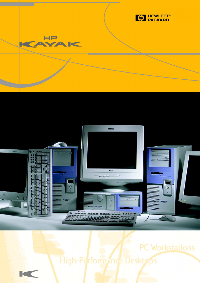
HP Kayak XM600
HP Kayak XU800


User’s Guide
Contents
Notice . . . . . . . . . . . . . . . . . . . . . . . . . . . . . . . . . . . . . . . . . . . . . . . . . . . 5
Important Warnings . . . . . . . . . . . . . . . . . . . . . . . . . . . . . . . . . . . . . . . 6
Information on Ergonomic Aspects . . . . . . . . . . . . . . . . . . . . . . . . . . 7
Information and Help. . . . . . . . . . . . . . . . . . . . . . . . . . . . . . . . . . . . . . 8
Technical Information . . . . . . . . . . . . . . . . . . . . . . . . . . . . . . . . . . . . 10
1 Setting Up and Using Your PC Workstation . . . . . . . . . . . . . . 11
Connecting Devices . . . . . . . . . . . . . . . . . . . . . . . . . . . . . . . . . . . . . . 12
The MaxiLife Status Panel. . . . . . . . . . . . . . . . . . . . . . . . . . . . . . . . . 13
Starting and Stopping Your PC Workstation. . . . . . . . . . . . . . . . . . 14
Using Your HP Enhanced Multimedia Keyboard
(some models only). . . . . . . . . . . . . . . . . . . . . . . . . . . . . . . . . . . . 16
Viewing the HP Summary Screen . . . . . . . . . . . . . . . . . . . . . . . . . . . 17
Using the HP Setup Program. . . . . . . . . . . . . . . . . . . . . . . . . . . . . . . 18
Setting Passwords in the HP Setup Program . . . . . . . . . . . . . . . . . 19
Using Power Management. . . . . . . . . . . . . . . . . . . . . . . . . . . . . . . . . 20
Manageability . . . . . . . . . . . . . . . . . . . . . . . . . . . . . . . . . . . . . . . . . . . 20
Software and Drivers . . . . . . . . . . . . . . . . . . . . . . . . . . . . . . . . . . . . . 20
2 Installing and Replacing Hardware Parts in Your
PC Workstation . . . . . . . . . . . . . . . . . . . . . . . . . . . . . . . . . . . . 21
Removing and Replacing the Cover and Front Bezel . . . . . . . . . . 23
Removing and Replacing the Airflow Guide . . . . . . . . . . . . . . . . . . 25
Removing and Replacing a Processor . . . . . . . . . . . . . . . . . . . . . . . 26
Removing, Replacing and Upgrading Memory
on HP Kayak XM600 Models Shipped with SDRAM . . . . . . . . . 28
Removing, Replacing and Upgrading Memory
on HP Kayak XM600 Models Shipped with RDRAM . . . . . . . . . 31
Memory Upgrades on the HP Kayak XU800 . . . . . . . . . . . . . . . . . . 32
Removing and Replacing a PCI Accessory Card . . . . . . . . . . . . . . 36
Installing Mass Storage Devices . . . . . . . . . . . . . . . . . . . . . . . . . . . . 38
Removing and Replacing the Primary Hard Disk Drive. . . . . . . . . 42
Installing a Second Hard Disk Drive in an Internal Shelf . . . . . . . 44
Installing a Third Hard Disk Drive . . . . . . . . . . . . . . . . . . . . . . . . . . 44
Installing an Accessory in the Front Access Cage . . . . . . . . . . . . . 45
Replacing the CD-ROM Drive (or DVD-Drive) . . . . . . . . . . . . . . . . 47
Replacing the Floppy Disk Drive . . . . . . . . . . . . . . . . . . . . . . . . . . . 48
Completing the Installation of a Mass Storage Device . . . . . . . . . 49
Replacing the Power Supply Unit. . . . . . . . . . . . . . . . . . . . . . . . . . . 50
Replacing the System Board . . . . . . . . . . . . . . . . . . . . . . . . . . . . . . 52
3

User’s Guide
Contents
Replacing the Rear Fan . . . . . . . . . . . . . . . . . . . . . . . . . . . . . . . . . . . . 54
Replacing the Fan and Speaker Assembly . . . . . . . . . . . . . . . . . . . . 56
System Board Switches. . . . . . . . . . . . . . . . . . . . . . . . . . . . . . . . . . . . 58
Replacing the Battery . . . . . . . . . . . . . . . . . . . . . . . . . . . . . . . . . . . . . 60
3 Troubleshooting Your HP PC Workstation . . . . . . . . . . . . . . 61
If Your PC Does Not Start Properly. . . . . . . . . . . . . . . . . . . . . . . . . . 62
If Your PC Has a Hardware Problem. . . . . . . . . . . . . . . . . . . . . . . . . 62
Using HP MaxiLife to Diagnose Problems . . . . . . . . . . . . . . . . . . . . 64
HP DiagTools Hardware Diagnostics Utility . . . . . . . . . . . . . . . . . . 69
Image Creation and Recovery CD-ROM . . . . . . . . . . . . . . . . . . . . . . 71
Frequently Asked Questions. . . . . . . . . . . . . . . . . . . . . . . . . . . . . . . . 74
Need More Help? . . . . . . . . . . . . . . . . . . . . . . . . . . . . . . . . . . . . . . . . . 75
Collecting Information Before Contacting HP Support . . . . . . . . . 76
4 Working in Comfort . . . . . . . . . . . . . . . . . . . . . . . . . . . . . . . . . 77
Regulatory Information. . . . . . . . . . . . . . . . . . . . . . . . . . . . . . 87
HP Software Product License Agreement and
Software Product Limited Warranty . . . . . . . . . . . . . . . . . . . 91
Index. . . . . . . . . . . . . . . . . . . . . . . . . . . . . . . . . . . . . . . . . . . . . 95
Part Number D8369-90101
4

Notice
The information contained in this document is subject to change without
notice.
Hewlett-Packard makes no warranty of any kind with regard to this
material, including, but not limited to, the implied warranties of
merchantability and fitness for a particular purpose. Hewlett-Packard shall
not be liable for errors contained herein or for incidental or consequential
damages in connection with the furnishing, performance, or use of this
material.
Hewlett-Packard assumes no responsibility for the use or reliability of its
software on equipment that is not furnished by Hewlett-Packard.
This document contains proprietary information that is protected by
copyright. All rights are reserved. No part of this document may be
photocopied, reproduced, or translated to another language without the
prior written consent of Hewlett-Packard Company.
Adobe® Reader © 1987-1997 Adobe Systems Incorporated. All rights
reserved. Adobe
TM
and AcrobatTM are trademarks of Adobe Systems
Incorporated.
Microsoft®, MS®, MS-DOS®, Windows®, and Windows NT® are U.S.
registered trademarks of Microsoft Corporation.
Pentium
TM
is a trademark of Intel Corporation.
Rambus and RDRAM are registered trademarks of Rambus Inc. Direct
Rambus, Direct RDRAM and RIMM are trademarks of Rambus Inc.
Hewlett-Packard France
Business Desktop Division (BDD)
38053 Grenoble Cedex 9
France
1999 Hewlett-Packard Company
5

Important Warnings
Avoid Electrical Shocks
WARNING To avoid electrical shock, do not open the power supply. There are no
user-serviceable parts inside.
To avoid electrical shock and harm to your eyes by laser light, do not
open the laser module. The laser module should only be serviced by
service personnel. Do not attempt to make any adjustment to the laser
unit. Refer to the label on the CD-ROM for power requirements and
wavelength. This product is a class I laser product.
Electrical
WARNING For your safety always connect equipment to a grounded wall outlet.
Always use a power cord with a properly grounded plug, such as the one
provided with the equipment, or one in compliance with your national
safety standards. This equipment can be disconnected from the power by
removing the power cord from the power outlet. This means the
equipment must be located close to an easily accessible power outlet.
Multimedia Models
WARNING If your PC is a multimedia model, or if you have installed an audio card in
your PC, always turn the volume down before connecting the
headphones or speakers. This avoids discomfort from unexpected noise
or static. Listening to loud sounds for prolonged periods of time may
permanently damage your hearing. Before putting on headphones, place
them around your neck and turn the volume down. When you put the
headphones on, slowly increase the volume until you find a comfortable
listening level. When you are able to hear comfortably and clearly,
without distortion, leave the volume in that position.
Removing and Replacing the Cover
WARNING For your safety, never remove the PC’s cover without first removing the
power cord from the power outlet and any connection to a
telecommunications network. Always replace the cover before switching
the PC on again.
6

Safety Information
WARNING There is a danger of explosion if the battery is incorrectly installed. For
your safety, never attempt to recharge, disassemble, or burn an old
battery. Only replace the battery with the same or equivalent type, as
recommended by the manufacturer. The battery in this PC is a lithium
battery which does not contain any heavy metals. Nevertheless, in order
to protect the environment, do not dispose of batteries in household
waste. Please return used batteries either to the shop from which you
bought them, to the dealer from whom you purchased your PC, or to HP
so that they can either be recycled or disposed of in the correct way .
Returned batteries will be accepted free of charge.
If you have a modem:
Do not attempt to connect this product to the phone line during a
lightning storm. Never install telephone jacks in wet locations unless the
telephone line has been disconnected at the network interface. Never
touch uninsulated telephone wires or terminals unless the telephone line
has been disconnected at the network interface. Use caution when
installing or modifying telephone lines. Avoid using a telephone (other
than a cordless type) during an lightning storm. There may be a risk from
lightning.
Do not use the telephone to report a gas leak in the vicinity of the leak.
Never touch or remove the communications board without first removing
the connection to the telephone network.
Unpacking Your PC Workstation
WARNING If you are in any doubt that you can lift the equipment safely, do not try
to move it without help.
Static Electricity
CAUTION Static electricity can damage electronic components. Turn OFF all
equipment. Don’t let your clothes touch the accessory. To equalize the
static electricity, rest the accessory bag on top of the PC Workstation
while you are removing the accessory from the bag. Handle the
accessory as little as possible and with care.
Information on Ergonomic Aspects
It is strongly recommended that you read the ergonomics information
contained in this manual (refer to page 77) before using your PC
Workstation. You can access this information from your PC by clicking the
Start button, and then Programs
➪ HP Info ➪ Working in Comfort.
7
If you want to ...
Information and Help
PC Workstation Documentation Roadmap
Access Information
Find Information
Set up your computer
Set up your computer
Learn how to use your
Learn how to use your
operating system
operating system
Learn how to upgrade
your computer by
installing accessories
Find out about the different
support options available,
and how to troubleshoot
your PC Workstation
Start ☞ Programs☞HP Info☞
Finding Information
Setup
This guide
Setting Up and Using Your PC Workstation
Reference
Operating System Online Help
☞ Help ☞Contents
Start
Operating System
User’s Guide
This guide
Troubleshooting and Support
HP Warranty and Support Guide
HP Support and Information Services
HP Troubleshooting Guide, downloadable
from: http://www.hp.com/go/kayaksupport
8

On HP’s Web Site
The HP web site contains a wide range of information, including
downloadable documentation, service and support options, and the latest
versions of drivers and utilities.
Downloadable Documentation
HP’s web site lets you download additional documentation for your
PC Workstation. This documentation is provided in Adobe Acrobat (PDF)
format.
The documentation for your PC Workstation is available free of charge on
the HP web site: http://www.hp.com/go/kayaksupport, then
select either HP Kayak XM600 or HP Kayak XU800 from the drop-down
menu.
This includes:
• Troubleshooting Guide — provides troubleshooting information.
• Technical Information — provides detailed information about your PC
Workstation, including:
System board switches, IRQs, DMAs, and I/O Addresses and Configuring
Your Network Connection.
• Service Handbook — provides information on replacement parts,
including HP part numbers.
NOTE To view and print the above guides, you need to have Adobe’s Acrobat
Reader installed on your PC Workstation. You can download it free of
charge from Adobe Systems Incorporated web site: www.adobe.com or
from the HP Kayak web site.
9

Technical Information
The following table shows standard configurations for HP Kayak XM600 and XU800 PC Workstations.
Characteristics: Description:
Weight (excl. keyboard and display) HP Kayak XM600: 14.2 kilograms (31.24 pounds).
HP Kayak XU800: 14.4 kilograms (31.68 pounds).
Dimensions 47.0 cm max. (D) by 21,0 cm (W) by 49.0 cm (H)
Footprint 0.09 m2 (1.06 sq ft).
Storage temperature -40 °C to 70°C (-40 °F to 158 °F).
Storage humidity 8% to 85% (relative).
Operating temperature 10 °C to 35 °C (50 °F to 95 °F).
Operating humidity 15% to 85% (relative).
Acoustic noise emission (as defined ISO
7779):
• Operating (typical)
Power supply • Input voltage: 100 - 127, 200 - 250 V (switch select)
(18.50 inches by 8.26 inches by 19.29 inches).
Sound Power
LwA < 42 dBA
For more information on acoustic data, refer to the PC
Workstation’s data sheet on HP’s web site at:
http://www.hp.com/desktops/kayak
• Input frequency: 50/60 Hz
• Maximum output power: 300 W continuous
• The maximum supported power consumption per PCI
accessory slot is 25 W, either from the 5 V and/or the
3.3 V supply and must respect the electrical
specification of the PCI 2.2 specification. Total power
consumption for the PCI slots must not exceed 75 W.
• The maximum power consumption tolerated in the AGP
PRO slot is limited to 50 W.
NOTE When the computer is turned off with the power button on the front panel, the
power consumption falls below 5 Watts, but is not zero. The special on/off method
used by these computers considerably extends the lifetime of the power supply. To
reach zero power consumption in “off” mode, either unplug the power outlet or use
a power block with a switch.
10

1
Setting Up and Using Your
PC Workstation
WARNING If you are in any doubt that you can lift the PC Workstation and the
display safely, do not try to move them without help.
1 When you receive your PC Workstation, unpack all of the components.
2 Place the PC Workstation on a sturdy desk with easily accessible power
outlets and enough space for the keyboard, mouse, and any other
accessories.
3 Position the PC Workstation so that its rear connectors are easily
accessible.
Installation Tools No tools are required to install your PC Workstation. However, if you plan to
install a disk drive or an accessory board inside your PC Workstation, you
will need a flat-blade screwdriver. For more information on installing
accessories, refer to "Installing and Replacing Hardware Parts in Your
PC Workstation", on page 21.
1 Setting Up and Using Your PC Workstation
Connecting Devices
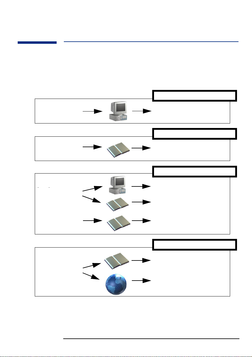
Connecting Devices
For your own safety, it is recommended that you first read the warning
notices on pages 6 and 7.
External SCSI
connector for HP
Kayak XU800
models only
Keyboard connector
Dual USB connectors
Serial port A
Serial port B
Line Out connector
Line In connector
Microphone connector
Display connector
Mouse connector
Parallel port
MIDI
connector
NOTE Universal Serial Bus (USB). Connectors can be used for USB
accessories. Most USB accessories are automatically configured as soon as
they are physically attached to the PC Workstation. USB accessories are
not supported by all operating systems.
Line Out Jack
. The internal audio speaker is deactivated when you use
the Line Out jack. External speakers should have a built-in power supply.
12
1 Setting Up and Using Your PC Workstation
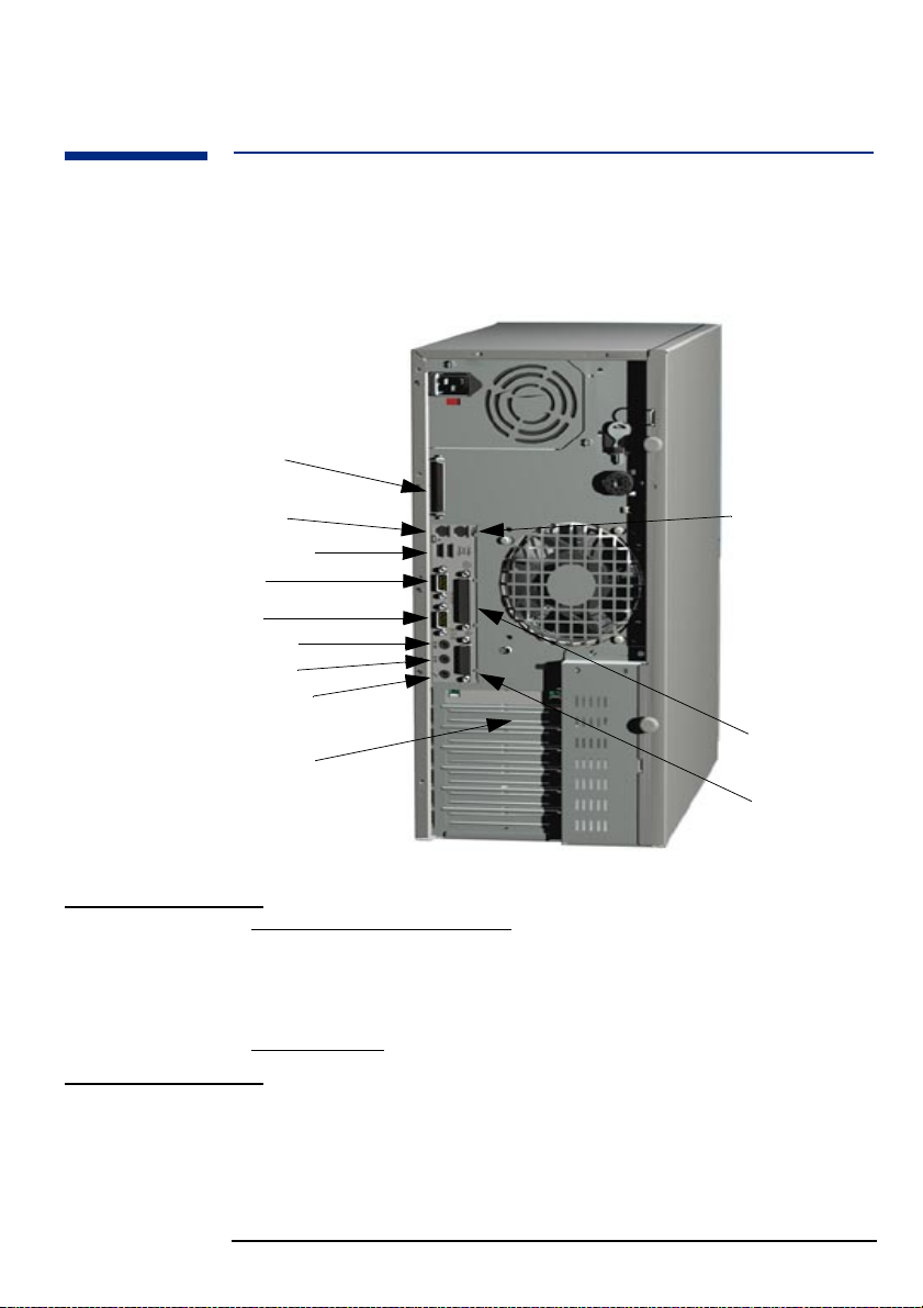
The MaxiLife Status Panel
The MaxiLife panel is located on the front of your PC Workstation.
LCD Control Buttons
PowerOn/Off
Button
Reset Button
Hard Disk
Activity Light
The MaxiLife Status Panel
HP MaxiLife and its
Liquid Crystal
Display (LCD)
Hard Disk Activity
Light
HP MaxiLife and its LCD screen helps you diagnose problems with your PC
Workstation and provides system information you may need to obtain
support. Press one of the LCD control buttons to display the menu. Use
to scroll through the menu items and to select the item required.
For more information on using the LCD, refer to “Using HP MaxiLife to
Diagnose Problems” on page 64.
This light flickers when your hard disk drive is being accessed.
13

1 Setting Up and Using Your PC Workstation
Starting and Stopping Your PC Workstation
Starting and Stopping Your PC Workstation
Starting Your PC Workstation for the First Time
If your PC Workstation has preinstalled software, it is initialized the first
time you start the PC Workstation. The software initialization process takes
a few minutes. This process sets up the software in your language and sets
up your software to use the hardware installed in your computer (you can
change the settings after the software has been initialized).
Starting Your PC Workstation
1 Before you start your PC Workstation, first switch on the display.
2 Start your PC Workstation in one of these ways:
• Press the power button on the front panel.
• Press the keyboard space bar (multimedia keyboard models only).
The keyboard power-on feature will work only if the appropriate
system board switch is set (default setting = enabled).
When you switch on the computer, it carries out the Power-On-SelfTest (POST) while the PC Workstation’s logo is displayed. If you wish to
view the details of this test, press . If there is an error in the POST,
the error will automatically be displayed.
3 If you have set a password in the PC Workstation’s Setup program, the
password prompt displays after the POST has completed. If the
Password prompt is displayed, type your password and press
to be able to use the PC Workstation.
14

1 Setting Up and Using Your PC Workstation
Starting and Stopping Your PC Workstation
Initializing Your Software
NOTE Do NOT switch OFF the PC Workstation while the software is being
initialized—this could cause unexpected results.
To initialize your software:
1 Turn on the display first, then the PC Workstation.
When the PC Workstation is switched on, the HP PC Workstation’s logo
is displayed. The PC Workstation performs a Power-On-Self-Test
(POST).
2 The software initialization process starts. It displays the software license
agreement, gives you an opportunity to read Working in Comfort
(ergonomics advice for computer users), then asks questions about the
PC Workstation.
3 While the initialization process is running, you can complete the
Warranty Registration card that came with this manual.
4 When the initialization process has finished, click OK and the
PC Workstation will restart.
Creating an Emergency Repair Disk
During the initialization of your software, it is very important that you
create an Emergency Repair Disk for the operating system, when
prompted. HP recommends that you use new diskettes for this purpose.
For more information on how to create these diskettes, refer to the
documentation that came with your application software or operating
system.
Stopping Your PC Workstation
To stop the PC Workstation, first make sure that you have exited all
applications and then use the shutdown command in the Start menu.
When prompted, press the power button on your PC Workstation’s control
panel.
CAUTION Do not use the power button until prompted to do so as you may lose
any unsaved data from open applications.
15
1 Setting Up and Using Your PC Workstation
Using Your HP Enhanced Multimedia Keyboard (some models only)
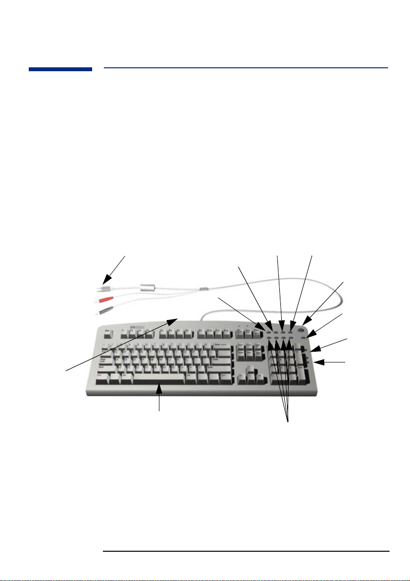
Using Your HP Enhanced Multimedia Keyboard
(some models only)
The HP enhanced multimedia keyboard includes soft keys you can use to:
• Display and configure the actions assigned to keys.
• Perform one-touch shortcuts to start applications, open files, or open
sites on the WWW.
• Launch the Internet browser supplied with your system.
• Lock or suspend your PC Workstation.
• Access HP TopTools and customer information.
• Mute or adjust the volume of the audio system.
• A headphone and microphone can be connected directly to the
keyboard. For this option to work, the headphone and microphone
connectors must be connected to their associated rear panel jacks.
Headphone and
Microphone
connectors can be
connected to the
rear panel.
Located
underneath the
keyboard top
edge, are the
Headphone and
Microphone
jacks.
Keyboard connector
Start key for space bar power on
HP TopTools
Internet key
Shortcut key
Menu key
Lock/Suspend key
HP Customer
Information
Mute key
Volume
control keys
Shortcut keys
Menu Key Pressing the “?” Menu soft key displays the soft key section of the HP
enhanced keyboard on your screen. Click any of the keys on the screen to
display the action assigned to an individual key or to change or assign an
action to a key. Shortcut keys are provided specifically for user-defined
actions.
16

1 Setting Up and Using Your PC Workstation
Viewing the HP Summary Screen
Viewing the HP Summary Screen
The HP Summary Screen gives you a summary of the current configuration
of your PC Workstation.
It is recommended that you check the configuration of your PC Workstation
when you first use it and each time after you install, remove, or upgrade
accessories. To check the configuration:
1 Turn on the display and then the PC Workstation. If the PC Workstation
is already turned on, save your data and exit all programs, then restart
the PC Workstation. Consult your operating system documentation for
any special instructions concerning turning off and restarting your PC
Workstation.
2 When the start-up logo appears on your display, press . This takes
you to the HP Summary Screen. (To go immediately into the Setup
program, and bypass the Summary Screen, press instead of ).
17

1 Setting Up and Using Your PC Workstation
Using the HP Setup Program
Using the HP Setup Program
Use the Setup program to configure your PC Workstation (for example:
setting up system and user passwords, installing and upgrading mass
storage devices), and to solve configuration problems.
It is recommended that you take note of any changes to the system setup.
NOTE Setup changes system behavior by modifying the power-on initialization
parameters. Setting incorrect values may cause system boot failure.
Should this occur, press to load the Setup default values to recover.
Starting the HP Setup Program
1 Turn on the display and then the PC Workstation. If the PC Workstation
is already turned on, save your data and exit all programs, then restart
the PC Workstation.
2 Press while Setup
If you fail to press in time and the start-up process continues, you
will need to restart your PC Workstation and go through the POST again
so you can press .
The opening screen of the PC Workstation’s Setup program is displayed.
The Main Menu presents a list of fields, for example, the installed BIOS
version or Date and Time.
A band along the top of the screen offers a list of menus. A menu is selected
by using either the left or right arrow keys.
For more information on the Setup program, refer to the Troubleshooting
Guide, available on the HP web site at:
http://www.hp.com/go/kayaksupport, then select either HP
Kayak XM600 or HP Kayak XU800 from the drop-down menu.
is displayed at the bottom of the screen.
18

1 Setting Up and Using Your PC Workstation
Setting Passwords in the HP Setup Program
Setting Passwords in the HP Setup Program
You can set passwords to provide different levels of protection for your PC
Workstation, the Administrator password, the User password and the
Power-on password. You set these passwords using the Security menu in the
Setup program.
The Administrator can access and change all settings in the Setup program,
while the User can only access and modify certain items in the Main menu.
When the Power-on Password option is enabled, you need to enter a
password everytime you boot the PC. Either the Administrator or User
Password can be used.
Setting a Password
To set a password:
1 Start the Setup program
2 Select the Security menu.
3 Select the Administrator or User password submenu.
4 Choose the Set Administrator or User password setup item. You will be asked
to enter your password twice.
To enable the Power-on Password, select the Enabled setup item.
5 To save your changes and exit the Setup program press or select
Exit Menu, then Exit Saving Changes.
To remove the password, follow the same procedure as to set a password.
You will be asked to enter the existing password first. Then, for the new
password, leave the password field blank and press . To confirm
your choice, press a second time.
19

1 Setting Up and Using Your PC Workstation
Using Power Management
Using Power Management
Power management enables you to reduce the PC’s overall power
consumption by slowing down the PC’s activity when it is idle.
For more information on power consumption data, refer to the PC
Workstation’s data sheet on HP’s web site at:
http://www.hp.com/desktops/kayak
Operating System Operating systems differ in their power management capabilities. Refer to
your operating system documentation for more information.
Manageability
Your PC is highly manageable. HP TopTools is a device management tool
that can help you in troubleshooting and makes remote administration
easier. For more information about TopTools, connect to HP’s web site at:
www.hp.com/toptools.
Software and Drivers
In the “Software and Drivers” section of the HP support site
http://www.hp.com/go/kayaksupport, then select either HP
Kayak XM600 or HP Kayak XU800 from the drop-down menu.
20
2
Installing and Replacing Hardware
Parts in Your PC Workstation
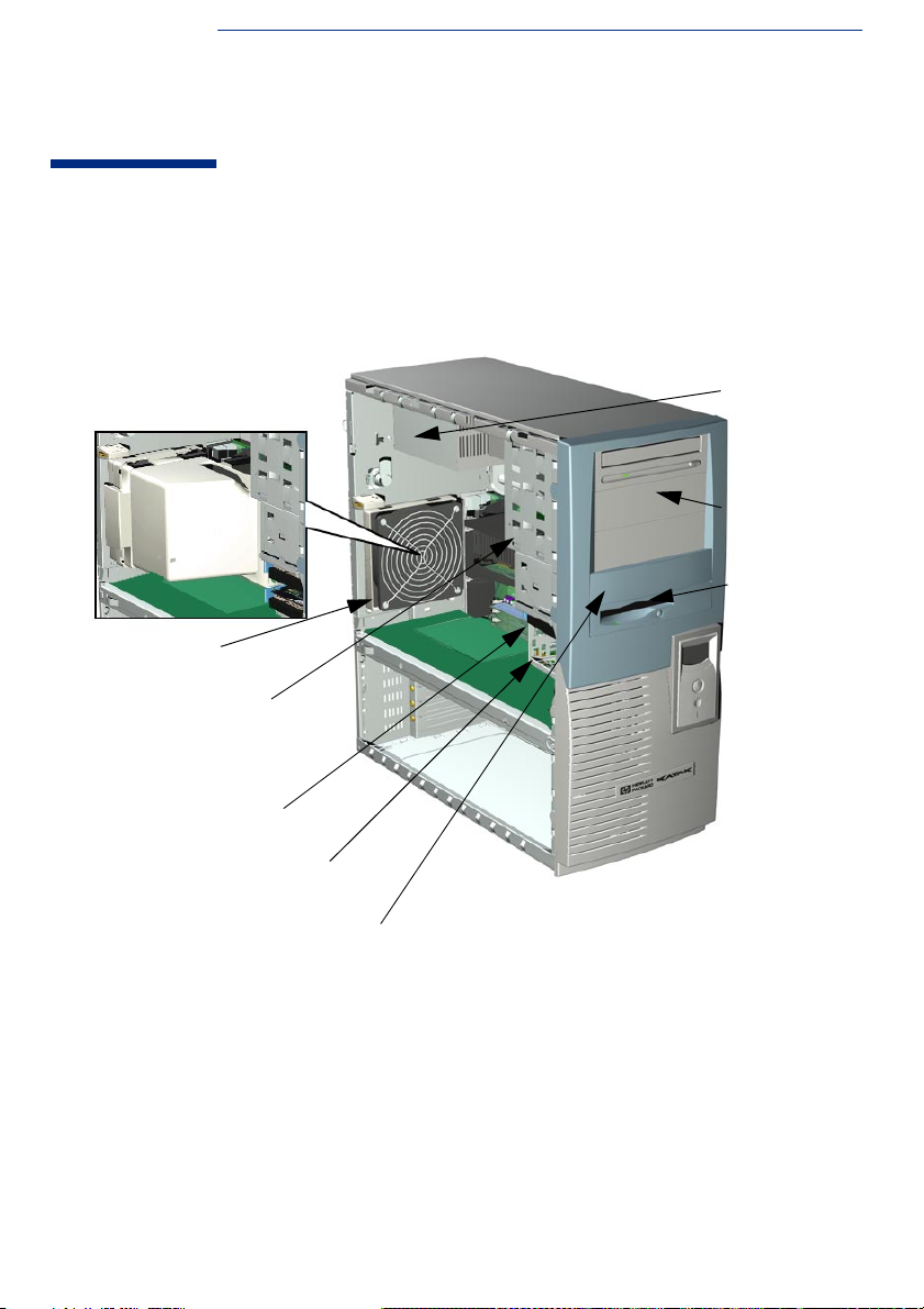
This chapter provides information about installing accessories and
replacing hardware parts in your PC Workstation.
HP UltraFlow Airflow Guide
Rear Fan
Spare mounting rails (not shown) for:
- 3.5-inch (short green) devices
(for example, zip drive),
- 5.25-inch (long green) devices,
- 3.5-inch (short blue) hard disk drives
Primary Hard Disk
Drive Shelf
Secondary Hard
Disk Drive Shelf
Power Supply Unit
Front Access
Drives, for
- three 5.25-inch
drive shelves
- two 3.5-inch
shelves including
a 1.44 MB floppy
disk drive
Second 3.5-inch shelf for zip drive
or second floppy disk drive
Contact your dealer for an up-to-date list of supported devices or check the
HP web site: http://www.hp.com/go/kayak.
2 Installing and Replacing Hardware Parts in Your PC Workstation
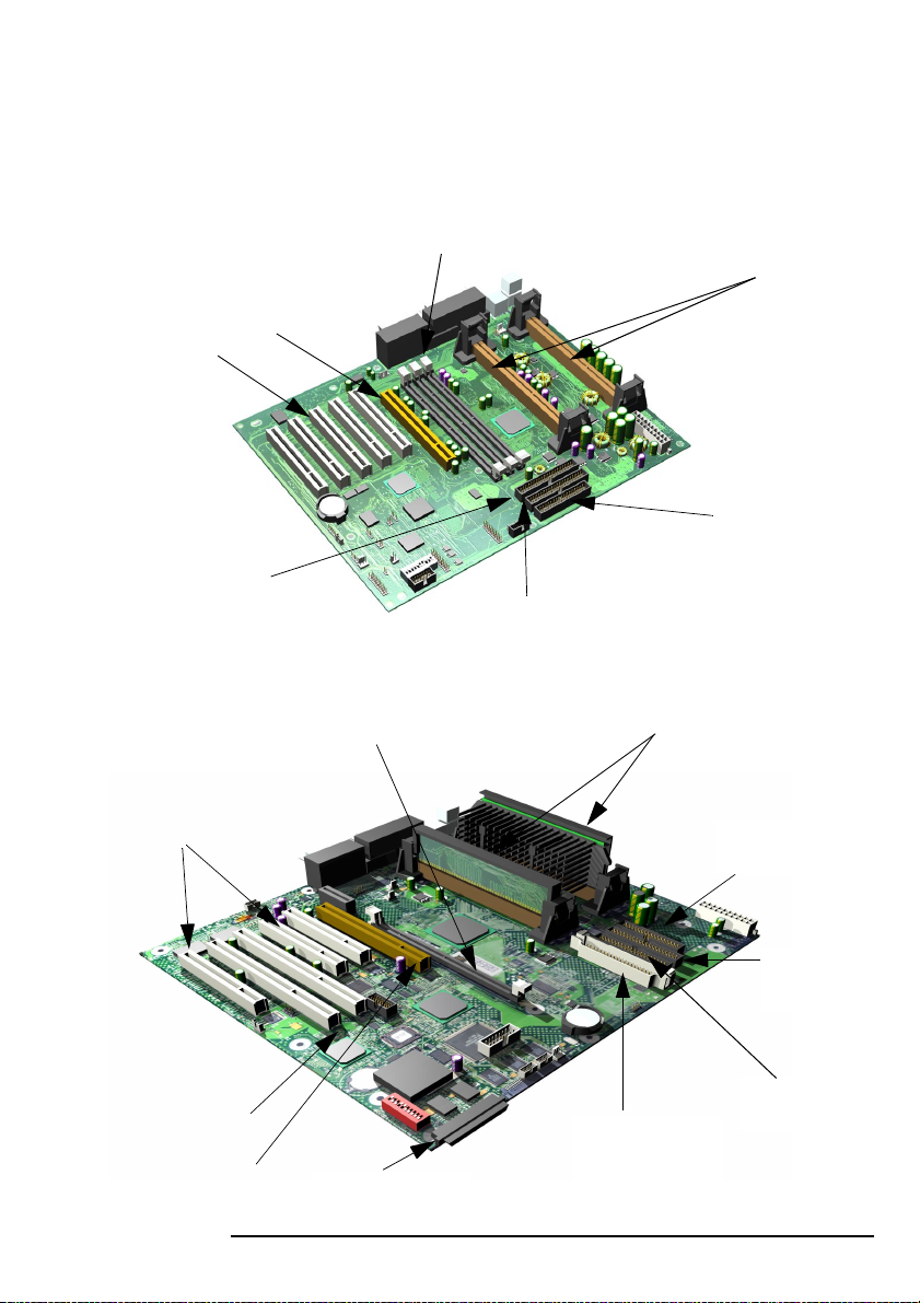
HP Kayak XM600 PC Workstation System Board
Depending on the model, the memory module sockets support either:
• Two RDRAM modules.
• Two SDRAM modules installed in a Memory Expansion Card.
Up to six accessory cards can be
installed:
- One Universal AGP PRO (graphics)
- Five 32-bit PCI slots
Primary IDE
Connector
HP Kayak XU800 PC Workstation System Board
Single Memory Expansion Card Connector, supp orting
either four RIMM sockets or, four DIMM sockets
Support for one or two
processors
Floppy Disk Drive
Connector
Secondary IDE Connector
Support for one or two
Pentium III processors
- PCI 1 slot (32-bits 33 MHz)
- PCI 2 slot (32-bits 33 MHz)
- PCI 5 slot (32-bits 33 MHz,)
- PCI 3 slot (64-bits 66 MHz)
- PCI 4 slot (64-bits 66 MHz)
One Universal AGP PRO
slot (graphics)
Floppy Disk Drive
Connector
Secondary
IDE Connector
Primary IDE
VRM socket. Only to be
used with second
16-bit Internal U160
68-pin SCSI connector
22
processor
Connector
2 Installing and Replacing Hardware Parts in Your PC Workstation
Removing and Replacing the Cover and Front Bezel
Removing and Replacing the Cover and Front Bezel
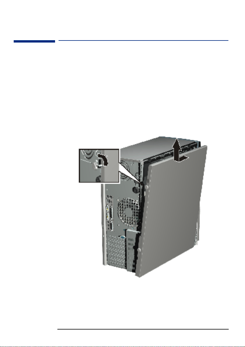
Removing the
Cover
For your own safety, it is recommended that you first read the warning
notices on pages 6 and 7.
1 Switch off the display and computer. Disconnect all power cables and
any LAN or telecommunications cables.
2 Unscrew the two thumb screws located at the back of the PC
Workstation.
3 Standing at the back of the PC Workstation, slide the cover towards you
until it clicks into place.
4 Tilt the cover sidewards, then lift off the PC Workstation chassis.
➍
Removing the
Front Bezel
5 If required, remove the front bezel which is divided into two sections:
• The upper bezel (blue) gives access to three 5.25-inch shelves and two
3.5-inch shelves.
• The lower bezel (grey) gives access to the control panel. To access the
lower bezel, you must first remove the upper bezel.
23

2 Installing and Replacing Hardware Parts in Your PC Workstation
Removing and Replacing the Cover and Front Bezel
NOTE Take care when removing the upper and lower bezels. They are not on a
hinge, so do not force them open.
To remove the upper and lower bezels:
a Unclip the two clips located on the left-hand side of the bezel.
b Open the bezel slightly, and then gently push it outwards.
➎a
➎b
➎a
Replacing the Cove r
and Front Bezel
1 Ensure that all internal cables are properly connected and safely routed.
2 If necessary, replace the front bezel. To do this, ensure that the bezel is
correctly orientated, align the two plastic tabs with their slots on the
right-hand side of the chassis, and then close the bezel. If you have
removed both sections of the front bezel, first replace the lower bezel.
3 Standing at the back of the PC, lower the cover onto the chassis (aligning
the guide rail on the bottom inside edge of the cover with the bottom
edge of the PC chassis).
4 Shut the cover ensuring that the guides on the top of the cover slide into
the rails at the top of the chassis.
5 Slide the cover forwards, then tighten the two thumbscrews.
6 If required, lock the cover using the key provided. Reconnect all the
power and telecommunications cables.
24
2 Installing and Replacing Hardware Parts in Your PC Workstation
Removing and Replacing the Airflow Guide
Removing and Replacing the Airflow Guide
Removing the HP
UltraFlow Airflow
Guide
Replacing the HP
UltraFlow Airflow
Guide
1 Switch off the display and PC Workstation. Disconnect all power cables
and any LAN or telecommunications cables.
2 Remove the PC Workstation’s cover (refer to page 23).
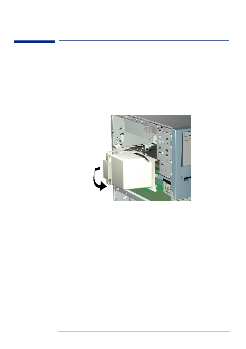
3 Grasp the handle on top of the HP UltraFlow Airflow Guide, then slide it
out of the PC Workstation.
4 Lift the HP UltraFlow Airflow Guide upwards to remove it from the PC
Workstation’s case.
1 Slide the HP UltraFlow Airflow Guide onto the processor fan housing
until it clicks into place.
2 Replace the PC Workstation’s cover (refer to page 24). Reconnect all the
power and telecommunications cables.
25

2 Installing and Replacing Hardware Parts in Your PC Workstation
Removing and Replacing a Processor
Removing and Replacing a Processor
Single-processor systems can be upgraded to dual-processor systems by
installing a second processor in the vacant processor slot. The second
processor must be of the same type, speed and level-2 cache memory
capacity as the first.
1 Switch off the display and PC Workstation. Disconnect all power cables
and any LAN or telecommunications cables.
2 Remove the PC Workstation’s cover (refer to page 23 for instructions).
3 Remove the HP UltraFlow Airflow Guide (refer to page 25).
4 If you intend to:
a Remove a Processor:
Press the retention clips on both sides of the processor outwards.
Then gently lift the processor upwards from the processor
connector, taking care not to tilt it too much.
b Install a Second Processor:
Remove the processor terminator from the CPU 2 connector. Store
the terminator in a safe place. For information about upgrading the
operating system, refer to "HP DualExpress!", on page 27.
26

2 Installing and Replacing Hardware Parts in Your PC Workstation
Removing and Replacing a Processor
Installing a
Processor
NOTE HP Kayak XU800 PC Workstations include a Voltage Regulator Module
NOTE The processor type and speed is automatically recognized by the BIOS.
1 Ensure that the edges of the processor are lined-up with the processor
connector guide rails along the retention mechanism.
2 Place one hand on the processor’s heatsink and push down onto the
processor connector. You hear two clicks as the retention mechanism
pops back, thereby locking the processor into the processor connector.
(VRM) socket on the system board. When installing a second processor,
the VRM delivered with the processor accessory kit must be installed in
this socket.
A VRM is not required on the HP Kayak XM600 PC Workstation.
3 Replace the HP UltraFlow Airflow Guide (refer to page 25).
4 Replace the PC Workstation’s cover (refer to page 24). Reconnect all the
power and telecommunications cables.
This means that no particular switch setting changes are required.
HP DualExpress!
Included with the HP Processor Accessory is the HP DualExpress!
application. This application is to be used when upgrading Windows NT
from a single-processor to a multi-processor system.
Using an installation Wizard, HP DualExpress! guides you through the
operating system upgrade which should take less than five minutes to
complete.
Launching HP
DualExpress!
The second processor must be installed and the PC booted. For now,
Windows NT will still only recognize the original processor. Insert the HP
DualExpress! floppy disk in the floppy disk drive and follow the
instructions. When the upgrade is complete, the system reboots. This time
a multi-processing system is recognized.
27
2 Installing and Replacing Hardware Parts in Your PC Workstation
Removing, Replacing and Upgrading Memory on Kayak XM600 models
Removing, Replacing and Upgrading Memory on Kayak
XM600 models
IMPORTANT NOTE This text was updated in December 2000 and replaces all earlier
information on memory replacement in the HP Kayak XM600.
Replacing SDRAM
SDRAM was available on some XM600 models shipped before May 2000.
Following an announcement made by the Intel Corporation that SDRAM
memory should not be used with the Intel 820 chipset (the chipset used in
the Kayak XM600) HP is replacing all SDRAM memory shipped with
RDRAM (RAMBUS DRAM) memory.
To determine whether you have SDRAM or RDRAM memory installed,
remove the cover of the PC. SDRAM models of the HP Kayak XM600 carry a
Memory Expansion Card supporting one or two Synchronized Dynamic
RAM (SDRAM) 100 MHz memory modules .
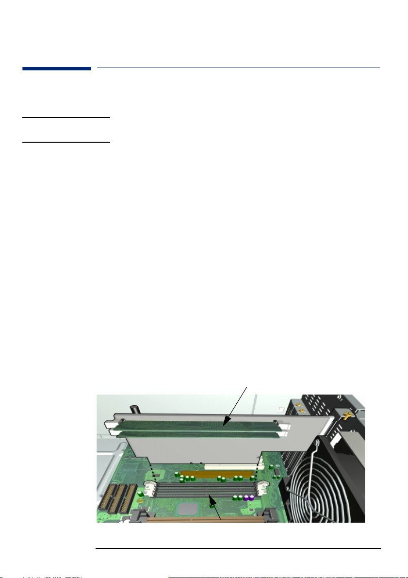
If a memory Expansion Card is installed, as shown below, then the PC
contains SDRAM memory.
To carry out the conversion, you should contact HP Support. You will then
be able to upgrade with RDRAM memory as described below.
The Memory Expansion Card is installed in a reserved memory socket on
the system board. This is the third socket, furthest from the processor(s).
The two remaining memory sockets on the system board, RIMM0 and
RIMM1 each contain a continuity module.
Removing the Memory Expansion Card
with one or two SDRAM module(s)
RIMM0 and RIMM1 sockets each contain
a continuity module
28

2 Installing and Replacing Hardware Parts in Your PC Workstation
Removing, Replacing and Upgrading Memory on Kayak XM600 models
Removing the Memory Expansion Card and SDRAM Modules
You cannot upgrade with RDRAM memory until the Memory Expansion
Card and all SDRAM memory has been removed.
Switch off the display and PC Workstation. Disconnect all power cables
1
and any LAN or telecommunications cables.
Remove the PC Workstation’s cover (refer to page 24 for detailed
2
instructions).
Remove the HP UltraFlow Airflow Guide to obtain access to the SDRAM
3
modules and sockets on the memory expansion card.
Release the retaining screw located on the Memory Expansion Card.
4
Then remove the screw from the accessory card socket.
Open the two retainin g cl ips on the system board to release the Memory
5
Expansion Card, then remove it from the connector.
Remove the memory modules from the old Memory Expansion Card. To
6
remove a memory module, open the two retaining clips and lift the
module out of the socket.
➏
➏
Install the replacement RDRAM module(s) with the necessary
7
Continuity and Terminator modules in the correct memory slots on the
mother board, as described in the following section “Upgrading RDRAM
Memory”.
29

2 Installing and Replacing Hardware Parts in Your PC Workstation
Removing, Replacing and Upgrading Memory on Kayak XM600 models
Upgrading RDRAM Memory
RDRAM models of the HP Kayak XM600 PC Workstation support one or
two RAMBUS Direct RAM (RDRAM) memory modules
NOTE Use only the HP memory modules provided for your PC model. If you want
to find out about available accessories for your PC, refer to the HP
Accessories Web site at:
If only one
one RDRAM module is installed
oneone
• it must be installed in the socket RIMM0, nearest the processor(s)
• the socket RIMM1 must contain an RDRAM Continuity Module
• the socket RIMM2 must contain an RDRAM Terminator Module.
If two
two RDRAM modules are installed
two two
• they must be installed in the two sockets nearest the processor(s),
RIMM0 and RIMM1
• ECC and non-ECC modules can be mixed, but if this is done, all memory
will operate in non-ECC mode
• the socket RIMM2 must contain an RDRAM Terminator Module.
http://www.hp.com/go/pcaccessories
Second RDRAM module, or
RDRAM Continuity Module
if unused
RDRAM Terminator Module
marked “CTRIMM”
First RDRAM module
Processor 2, or processor
terminator card if unused
Processor 1
System board edge
30
Loading...