


HP HLMP-6204, HLMP-6205, HLMP-6206, HLMP-6208, HLMP-6300 Datasheet
...H
Subminiature LED Lamps
Technical Data
Features
•Subminiature Flat Top Package
Ideal for Backlighting and Light Piping Applications
•Subminiature Dome Package
Diffused Dome for Wide Viewing Angle Nondiffused Dome for High Brightness
HLMP-PXXX Series
HLMP-QXXX Series
HLMP-6XXX Series
HLMP-70XX Series
Dome Packages
The HLMP-6XXX Series dome lamps for use as indicators use a tinted, diffused lens to provide a wide viewing angle with a high on-off contrast ratio. High brightness lamps use an untinted, nondiffused lens to provide a high luminous intensity within a narrow radiation pattern.
•Arrays
•TTL and LSTTL Compatible 5 Volt Resistor Lamps
•Available in Six Colors
•Ideal for Space Limited Applications
•Axial Leads
•Available with Lead Configurations for Surface Mount and Through Hole PC Board Mounting
Description
Flat Top Package
The HLMP-PXXX Series flat top lamps use an untinted, nondiffused, truncated lens to provide a wide radiation pattern that is necessary for use in backlighting applications. The flat top lamps are also ideal for use as emitters in light pipe applications.
Arrays
The HLMP-66XX Series subminiature lamp arrays are available in lengths of 3 to 8 elements per array. The luminous intensity is matched within an array to assure a 2.1 to 1.0 ratio.
Resistor Lamps
The HLMP-6XXX Series 5 volt subminiature lamps with built in current limiting resistors are for use in applications where space is at a premium.
Lead Configurations
All of these devices are made by encapsulating LED chips on axial lead frames to form molded epoxy subminiature lamp packages. A variety of package configuration options is available. These include special
surface mount lead configurations, gull wing, yoke lead or Z- bend. Right angle lead bends at 2.54 mm (0.100 inch) and
5.08 mm (0.200 inch) center spacing are available for through hole mounting. For more information refer to Standard SMT and Through Hole Lead Bend Options for Subminiature LED Lamps data sheet.
1-174 |
5964-9350E |
Device Selection Guide
Part Number: HLMP-XXXX
|
DH AS |
High |
|
|
High |
|
|
|
Device |
Standard |
AlGaAs |
Efficiency |
|
|
Perf. |
Emerald |
|
|
Outline |
Red |
Red |
Red |
Orange |
Yellow |
Green |
Green |
Device Description[1] |
Drawing |
|
|
P105 |
P205 |
P405 |
P305 |
P505 |
P605 |
Untinted, Nondiffused, |
A |
|
|
|
|
|
|
|
|
Flat Top |
|
|
|
|
|
|
|
|
|
|
|
|
|
P102 |
P202 |
P402 |
P302 |
P502 |
|
Untinted, Diffused, |
B |
|
|
|
|
|
|
|
|
Flat Top |
|
|
|
|
|
|
|
|
|
|
|
|
6000/6001 |
Q101 |
6300 |
Q400 |
6400 |
6500 |
Q600 |
Tinted, Diffused |
|
|
|
|
|
|
|
|
|
|
|
|
|
Q105 |
6305 |
|
6405 |
6505 |
|
Untinted, Nondiffused, |
|
|
|
|
|
|
|
|
|
High Brightness |
|
|
|
|
|
|
|
|
|
|
|
|
|
Q150 |
7000 |
|
7019 |
7040 |
|
Tinted, Diffused, Low |
B |
|
|
|
|
|
|
|
|
Current |
|
|
|
|
|
|
|
|
|
|
|
|
|
Q155 |
|
|
|
|
|
Nondiffused, Low |
|
|
|
|
|
|
|
|
|
Current |
|
|
|
|
|
|
|
|
|
|
|
|
|
|
6600 |
|
6700 |
6800 |
|
Tinted, Diffused, |
|
|
|
|
|
|
|
|
|
Resistor, 5 V, 10 mA |
|
|
|
|
|
|
|
|
|
|
|
|
|
|
6620 |
|
6720 |
6820 |
|
Diffused, Resistor, 5 V, |
|
|
|
|
|
|
|
|
|
4 mA |
|
|
|
|
|
|
|
|
|
|
|
|
6203 |
|
6653 |
|
6753 |
6853 |
|
3 Element |
Matched |
|
|
|
|
|
|
|
|
|
|
|
6204 |
|
6654 |
|
6754 |
6854 |
|
4 Element |
Array, |
|
|
|
|
|
|
|
|
|
Tinted, |
|
6205 |
|
6655 |
|
6755 |
6855 |
|
5 Element |
Diffused |
C |
|
|
|
|
|
|
|
|
|
|
6206 |
|
6656 |
|
6756 |
6856 |
|
6 Element |
|
|
|
|
|
|
|
|
|
|
|
|
6208 |
|
6658 |
|
6758 |
6858 |
|
8 Element |
|
|
|
|
|
|
|
|||||
|
|
|
|
|
|
|
|
|
|
Package Dimensions
(A) Flat Top Lamps
NOTES: |
|
1. ALL DIMENSIONS ARE IN MILLIMETERS (INCHES). |
*Refer to Figure 1 for design concerns. |
2. PROTRUDING SUPPORT TAB IS CONNECTED TO CATHODE LEAD. |
1-175

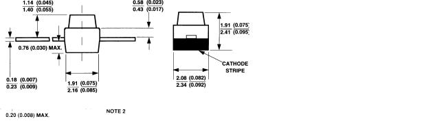
Package Dimensions (cont.)
(B) Diffused and Nondiffused
NOTES: |
|
1. ALL DIMENSIONS ARE IN MILLIMETERS (INCHES). |
*Refer to Figure 1 for design concerns. |
2. PROTRUDING SUPPORT TAB IS CONNECTED TO CATHODE LEAD. |
(C) Arrays
NOTES:
1.ALL DIMENSIONS ARE IN MILLIMETERS (INCHES).
2.PROTRUDING SUPPORT TAB IS CONNECTED TO CATHODE LEAD.
Figure 1. Proper Right Angle Mounting to a PC Board to Prevent Protruding Cathode Tab from Shorting to Anode Connection.
1-176
Absolute Maximum Ratings at TA = 25°C
|
|
DH AS |
High |
|
|
|
High |
|
|
|
Standard |
AlGaAs |
Eff. |
|
|
|
Perf. |
Emerald |
|
Parameter |
Red |
Red |
Red |
Orange |
|
Yellow |
Green |
Green |
Units |
|
|
|
|
|
|
|
|
|
|
DC Forward Current[1] |
50 |
30 |
30 |
30 |
|
20 |
30 |
30 |
mA |
Peak Forward Current[2] |
1000 |
300 |
90 |
90 |
|
60 |
90 |
90 |
mA |
|
|
|
|
|
|
|
|
|
|
DC Forward Voltage |
|
|
6 |
|
|
6 |
6 |
6 |
V |
(Resistor Lamps Only) |
|
|
|
|
|
|
|
|
|
|
|
|
|
|
|
|
|
|
|
Reverse Voltage (IR = 100 μA) |
5 |
5 |
5 |
5 |
|
5 |
5 |
5 |
V |
|
|
|
|
|
|
|
|
|
|
Transient Forward Current[3] |
2000 |
500 |
500 |
500 |
|
500 |
500 |
500 |
mA |
(10 μs Pulse) |
|
|
|
|
|
|
|
|
|
|
|
|
|
|
|
|
|
|
|
Operating Temperature Range: |
-55 to |
-40 to |
|
-55 to +100 |
-40 to |
-20 to |
|
||
Non-Resistor Lamps |
+100 |
+100 |
|
|
|
|
+100 |
+100 |
°C |
|
|
|
|
|
|
|
|
|
|
Resistor Lamps |
|
|
|
-40 to +85 |
-20 to |
||||
|
|
|
|
||||||
|
|
|
|
|
|
|
+85 |
|
|
|
|
|
|
|
|
|
|
|
|
Storage Temperature Range |
|
|
|
-55 to +100 |
|
|
|
°C |
|
|
|
|
|
|
|
|
|
|
|
For Thru Hole Devices |
|
|
260°C for 5 Seconds |
|
|
|
|||
Wave Soldering Temperature |
|
|
|
|
|
|
|
|
|
[1.6 mm (0.063 in.) from body] |
|
|
|
|
|
|
|
|
|
|
|
|
|
|
|
|
|
|
|
For Surface Mount Devices: |
|
|
235°C for 90 Seconds |
|
|
|
|||
Convective IR |
|
|
|
|
|
||||
|
|
|
|
|
|
|
|
|
|
Vapor Phase |
|
|
215°C for 3 Minutes |
|
|
|
|||
|
|
|
|
|
|
|
|
|
|
Notes:
1.See Figure 5 for current derating vs. ambient temperature. Derating is not applicable to resistor lamps.
2.Refer to Figure 6 showing Max. Tolerable Peak Current vs. Pulse Duration to establish pulsed operating conditions.
3.The transient peak current is the maximum non-recurring peak current the device can withstand without failure. Do not operate these lamps at this high current.
1-177
Electrical/Optical Characteristics, TA = 25°C
Standard Red
Device |
|
|
|
|
|
|
|
|
HLMP- |
Parameter |
Symbol |
Min. |
Typ. |
Max. |
Units |
Test Conditions |
|
|
|
|
|
|
|
|
|
|
6000 |
|
|
|
0.5 |
1.2 |
|
|
|
|
|
|
|
|
|
|
|
|
6001 |
Luminous Intensity[1] |
I |
v |
1.3 |
3.2 |
|
mcd |
I = 10 mA |
|
|
|
|
|
|
|
F |
|
6203 to |
|
|
|
0.5 |
1.2 |
|
|
|
6208 |
|
|
|
|
|
|
|
|
|
|
|
|
|
|
|
|
|
|
Forward Voltage |
VF |
1.4 |
1.6 |
2.0 |
V |
IF = 10 mA |
|
|
|
|
|
|
|
|
|
|
All |
Reverse Breakdown |
VR |
5.0 |
12.0 |
|
V |
IR = 100 μA |
|
|
Voltage |
|
|
|
|
|
|
|
P005 |
Included Angle Between |
2θ1/2 |
|
125 |
|
|
|
|
|
Half Intensity Points[2] |
|
|
|
Deg. |
|
||
All |
|
90 |
|
|
||||
|
|
|
|
|
|
|
||
Others |
|
|
|
|
|
|
|
|
|
|
|
|
|
|
|
|
|
|
Peak Wavelength |
λPEAK |
|
655 |
|
nm |
|
|
|
Dominant Wavelength[3] |
λd |
|
640 |
|
nm |
|
|
|
Spectral Line Half Width |
Δλ1/2 |
|
24 |
|
nm |
|
|
All |
Speed of Response |
τs |
|
15 |
|
ns |
|
|
|
Capacitance |
C |
|
100 |
|
pF |
VF = 0; f = 1 MHz |
|
|
|
|
|
|
|
|
|
|
|
Thermal Resistance |
RθJ-PIN |
|
170 |
|
°C/W |
Junction-to-Cathode |
|
|
|
|
|
|
|
|
|
Lead |
|
Luminous Efficacy[4] |
η |
|
65 |
|
lm/W |
|
|
|
|
|
v |
|
|
|
|
|
1-178
 Loading...