


HFBR-2416T
HP HFBR-2416T, HFBR-2416M, HFBR-2416K, HFBR-2416HB, HFBR-2416HA Datasheet
...
46
Transmitters and receivers are
directly compatible with popular
“industry-standard” connectors:
ST, SMA, SC and FC. They are
completely specified with
multiple fiber sizes; including
50/125 µm, 62.5/125 µm, 100/
140 µm, and 200 µm.
Complete evaluation kits are
available for ST and SMA product
offerings; including transmitter,
receiver, connectored cable, and
technical literature. In addition,
ST and SMA connectored cables
are available for evaluation.
Low Cost, Miniature Fiber
Optic Components with ST®,
SMA, SC and FC Ports
Technical Data
HFBR-0400 Series
Features
• Meets IEEE 802.3 Ethernet
and 802.5 Token Ring
Standards
• Low Cost Transmitters and
Receivers
• Choice of ST®, SMA, SC or
FC Ports
• 820 nm Wavelength
Technology
• Signal Rates up to 175
Megabaud
• Link Distances up to 4 km
• Specified with 50/125 µm,
62.5/125 µm, 100/140 µm,
and 200 µm HCS
®
Fiber
• Repeatable ST Connections
within 0.2 dB Typical
• Unique Optical Port Design
for Efficient Coupling
• Auto-Insertable and Wave
Solderable
• No Board Mounting Hardware Required
• Wide Operating
Temperature Range
-40°C to 85°C
• AlGaAs Emitters 100%
Burn-In Ensures High
Reliability
• Conductive Port Option with
the SMA and ST Threaded
Port Styles
Applications
• Local Area Networks
• Computer to Peripheral
Links
• Computer Monitor Links
• Digital Cross Connect Links
• Central Office Switch/PBX
Links
• Video Links
• Modems and Multiplexers
• Suitable for Tempest
Systems
• Industrial Control Links
Description
The HFBR-0400 Series of components is designed to provide cost
effective, high performance fiber
optic communication links for
information systems and
industrial applications with link
distances of up to 4 kilometers.
With the HFBR-24X6, the 125
MHz analog receiver, data rates
of up to 175 megabaud are
attainable.
ST® is a registered trademark of AT&T.
HCS® is a registered trademark of the SpecTran Corporation.
5965-1655E (1/97)
47
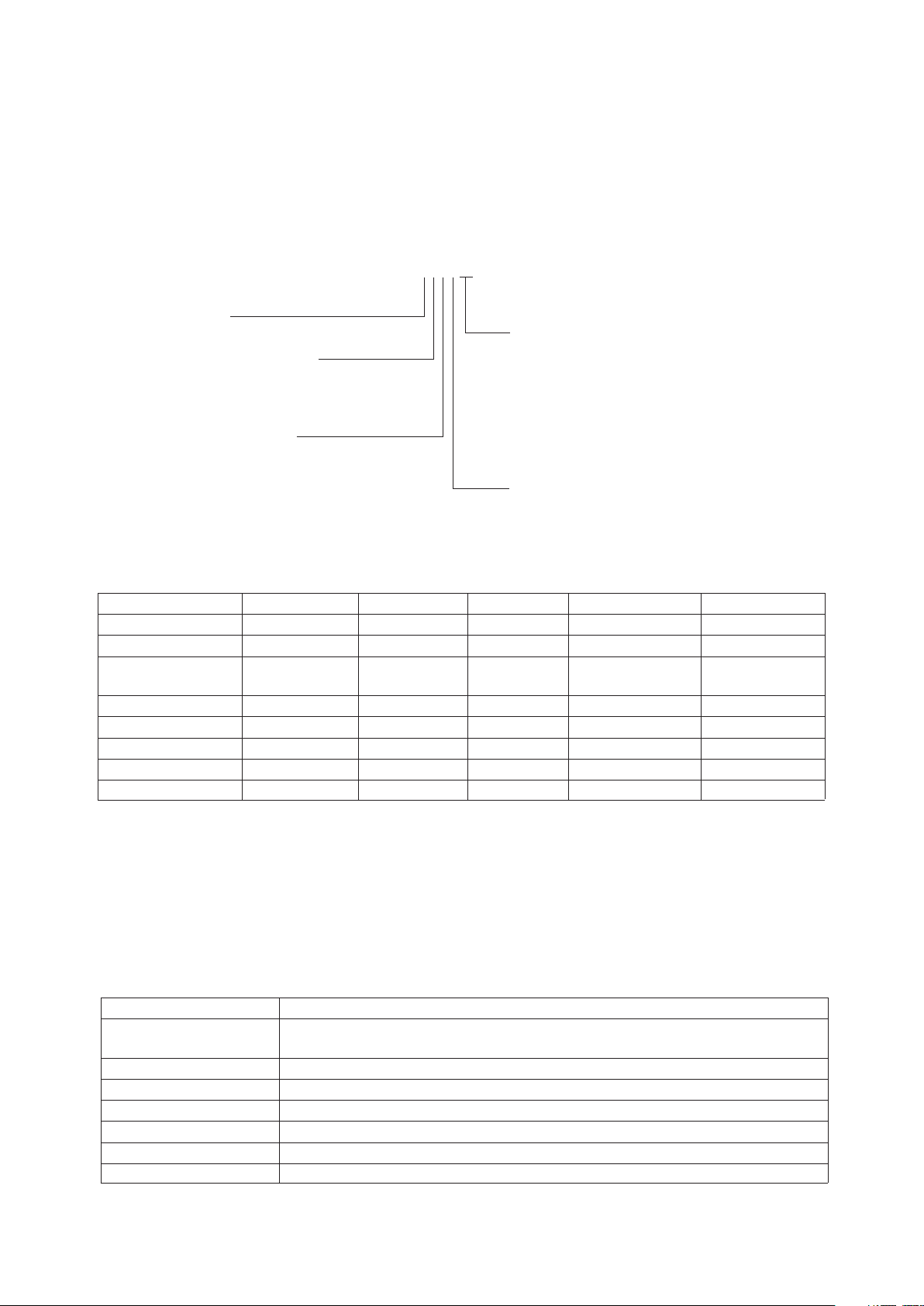
HFBR-0400 Series Part Number Guide
HFBR X4XXaa
1 = Transmitter Option T (Threaded Port Option)
2 = Receiver Option C (Conductive Port Receiver Option)
Option M (Metal Port Option)
4 = 820 nm Transmitter and Option K (Kinked Lead Option)
Receiver Products TA = Square pinout/straight lead
TB = Square pinout/bent leads
0 = SMA, Housed HA = Diamond pinout/straight leads
1 = ST, Housed HB = Diamond pinout/bent leads
2 = FC, Housed
E = SC, Housed 2 = Tx, Standard Power
3 = SMA Port, 90 deg. Bent Leads 4 = Tx, High Power
4 = ST Port, 90 deg. Bent Leads 2 = Rx, 5 MBd, TTL Output
5 = SMA Port, Straight Leads 6 = Rx, 125 MHz, Analog Output
6 = ST Port, Straight Leads
LINK SELECTION GUIDE
Data Rate (MBd) Distance (m) Transmitter Receiver Fiber Size (µm) Evaluation Kit
5 1500 HFBR-14X2 HFBR-24X2 200 HCS N/A
5 2000 HFBR-14X4 HFBR-24X2 62.5/125 HFBR-04X0
20 2700 HFBR-14X4 HFBR-24X6 62.5/125 HFBR-0414,
HFBR-0463
32 2200 HFBR-14X4 HFBR-24X6 62.5/125 HFBR-0414
55 1400 HFBR-14X4 HFBR-24X6 62.5/125 HFBR-0414
125 700 HFBR-14X4 HFBR-24X6 62.5/125 HFBR-0416
155 600 HFBR-14X4 HFBR-24X6 62.5/125 HFBR-0416
175 500 HFBR-14X4 HFBR-24X6 62.5/125 HFBR-0416
For additional information on specific links see the following individual link descriptions. Distances measured over temperature range
from 0 to 70°C.
Applications Support
Guide
This section gives the designer
information necessary to use the
HFBR-0400 series components to
make a functional fiber-optic
transceiver. HP offers a wide
selection of evaluation kits for
hands-on experience with fiberoptic products as well as a wide
Application Literature
Title Description
HFBR-0400 Series Transmitter & Receiver Reliability Data
Reliability Data
Application Bulletin 73 Low Cost Fiber Optic Transmitter & Receiver Interface Circuits
Application Bulletin 78 Low Cost Fiber Optic Links for Digital Applications up to 155 MBd
Application Note 1038 Complete Fiber Solutions for IEEE 802.3 FOIRL, 10Base-FB and 10 Base-FL
Application Note 1065 Complete Solutions for IEEE 802.5J Fiber-Optic Token Ring
Application Note 1073 HFBR-0319 Test Fixture for 1X9 Fiber Optic Transceivers
Application Note 1086 Optical Fiber Interconnections in Telecommunication Products
range of application notes complete with circuit diagrams and
board layouts. Furthermore, HP’s
application support group is
always ready to assist with any
design consideration.

48
HFBR-0400 Series
Evaluation Kits
HFBR-0410 ST Evaluation Kit
Contains the following :
• One HFBR-1412 transmitter
• One HFBR-2412 five megabaud
TTL receiver
• Three meters of ST connectored 62.5/125 (µm fiber optic
cable with low cost plastic
ferrules.
• Related literature
HFBR-0414 ST Evaluation Kit
Includes additional components
to interface to the transmitter and
receiver as well as the PCB to
reduce design time.
Contains the following:
• One HFBR-1414T transmitter
• One HFBR-2416T receiver
• Three meters of ST connectored 62.5/125 µm fiber optic
cable
• Printed circuit board
• ML-4622 CP Data Quantizer
• 74ACTllOOON LED Driver
• LT1016CN8 Comparator
• 4.7 µH Inductor
• Related literature
HFBR-0400 SMA Evaluation
Kit
Contains the following :
• One HFBR-1402 transmitter
• One HFBR-2402 five megabaud
TTL receiver
• Two meters of SMA
connectored 1000 µm plastic
optical fiber
• Related literature
HFBR-0416 Evaluation Kit
Contains the following:
• One fully assembled 1x9
transceiver board for 155 MBd
evaluation including:
-HFBR-1414 transmitter
-HFBR-2416 receiver
-circuitry
• Related literature
HFBR-0463 Ethernet MAU
Evaluation Kit
Contains the following:
• One fully assembled Media
Attachment Unit (MAU) board
which includes:
-HFBR-1414 transmitter
-HFBR-2416 receiver
-HFBR-4663 IC
• Related literature
Note: Cable not included. Order
HFBR-BXS010 seperately (2
pieces)
Package and Handling
Information
Package Information
All HFBR-0400 Series
transmitters and receivers are
housed in a low-cost, dual-inline
package that is made of high
strength, heat resistant, chemically resistant, and UL 94V-O
flame retardant ULTEM® (plastic
(UL File #E121562). The
transmitters are easily identified
by the light grey color connector
port. The receivers are easily
identified by the dark grey color
connector port. (Black color for
conductive port.) The package is
designed for auto-insertion and
wave soldering so it is ideal for
high volume production
applications.
Handling and Design
Information
Each part comes with a protective
port cap or plug covering the
optics. These caps/plugs will vary
by port style. When soldering, it
is advisable to leave the protective cap on the unit to keep the
optics clean. Good system
performance requires clean port
optics and cable ferrules to avoid
obstructing the optical path.
Clean compressed air often is
sufficient to remove particles of
dirt; methanol on a cotton swab
also works well.
Recommended Chemicals for
Cleaning/Degreasing
HFBR-0400 Products
Alcohols: methyl, isopropyl,
isobutyl. Aliphatics: hexane,
heptane, Other: soap solution,
naphtha.
Do not use partially halogenated
hydrocarbons such as 1,1.1
trichloroethane, ketones such as
MEK, acetone, chloroform, ethyl
acetate, methylene dichloride,
phenol, methylene chloride, or
N-methylpyrolldone. Also, HP
does not recommend the use of
cleaners that use halogenated
hydrocarbons because of their
potential environmental harm.
Ultem® is a registered Trademark of the GE corporation.
49
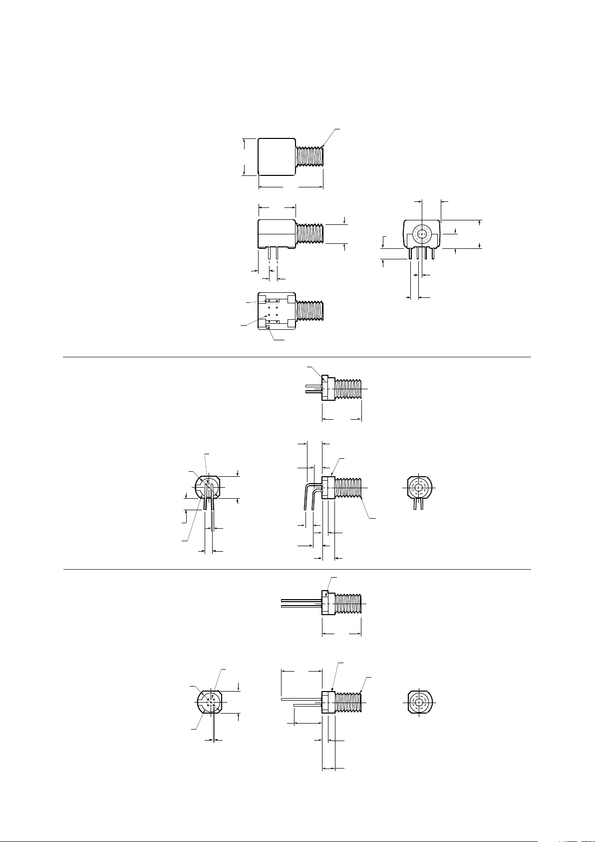
Mechanical Dimensions
HFBR-0400 SMA Series
HFBR-X43X
HFBR-X45X
HFBR-X40X
13.2
(052)
2.5
(0.10)
DIA
NOTE 2
NOTE: ALL DIMENSIONS IN MILLIMETRES AND (INCHES).
13.0
(0.51)
2.0
(0.08)
9.1
(0.36)
7.1
(0.28)
PART MARKING
.46
(0.018)
YY WW
4.1
(0.16)
1/4 - 36 UNS 2A
THREAD8.6
(0.34)
DIA
12
34
DIA PIN
CIRCLE
7.1
(0.28)
DIA
YY WW
2.5
(0.10)
7.1
(0.28)
TYP
NOTE 2
8.6
(0.34)
DIA
2.5
(0.10)
DIA PIN
CIRCLE
12
34
0.46
(0.018)
DIA
TYP
4.8
(0.19)
2.3
(0.09)
2.0
(0.08)
4.1
(0.16)
2.5
(0.10)
3.0
(0.12)
TYP
TYP
TYP
TYP
7.1
(0.28)
DIA
13.0
(0.51)
PART MARKING
1/4 - 36 UNS 2A
THREAD
3.6
(0.14)
MIN
6.35
(0.25)
2.54
(0.10)
3.81
(0.15)
6.4
(0.25)
DIA
12.7
(0.50)
12.7
(0.50)
22.2
(0.87)
5.1
(0.20)
10.2
(0.40)
3.6
(0.14)
1.27
(0.05)
2.54
(0.10)
PINS 1,4,5,8
0.51 X 0.38
(0.020 X 0.015)
PINS 2,3,6,7
0.46
(0.018)
DIA.
8
1
3
524
6
7
PIN NO. 1
INDICATOR
1/4 - 36 UNS 2A THREAD
Rx/Tx
COUNTRY OF
ORIGIN
hp YYWW
HFBR-X40X
50
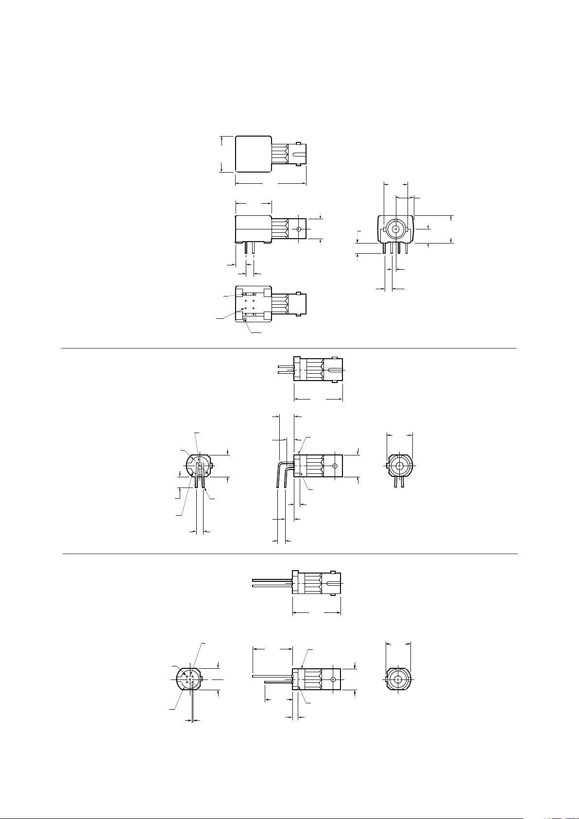
Mechanical Dimensions
HFBR-0400 ST Series
HFBR-X44X
HFBR-X46X
HFBR-X41X
13.2
(0.52)
2.5 (0.10)
DIA PIN
CIRCLE
8.6
(0.34)
PIN DIA
NOTE 2
DIA
NOTE: ALL DIMENSIONS IN MILLIMETRES AND (INCHES).
18.6
(0.73)
7.0
(0.28)
7.1
(0.28)
7.1
(0.28)
2.O
(0.08)
0.46
(0.018)
21
34
8.2
(0.32)
9.1
(0.36)
DIA
DIA
X-YWW
PART MARKING
2.5
(0.10)
7.1
(0.28)
3.6
(0.14)
TYP
NOTE 2
DIA
2.5
(0.10)
DIA PIN
CIRCLE
12
34
0.46 (0.018)
PIN DIA
4.9
(0.19)
2.4
(0.09)
2.0
(0.08)
7.0
(0.28)
3.0
(0.12)
2.5
(0.10)
TYP
TYP
TYP
TYP
7.1
(0.28)
DIA
18.6
(0.73)
8.6
(0.34)
MIN
8.2
8.2
(0.32)
DIA
X-YWW
PART MARKING
6.35
(0.25)
2.54
(0.10)
3.81
(0.15)
7.0
(0.28)
DIA
12.7
(0.50)
12.7
(0.50)
27.2
(1.07)
5.1
(0.20)
10.2
(0.40)
3.6
(0.14)
8.2
(0.32)
1.27
(0.05)
2.54
(0.10)
PINS 1,4,5,8
0.51 X 0.38
(0.020 X 0.015)
PINS 2,3,6,7
0.46
(0.018)
DIA
8
13
5
2
4
6
7
PIN NO. 1
INDICATOR
Rx/Tx
COUNTRY OF
ORIGIN
hp YYWW
HFBR-X41X
51
Mechanical Dimensions
HFBR-0400T Threaded
ST Series
HFBR-X44XT
HFBR-X46XT
HFBR-X41XT
8
1
3
5
24
6
7
DIA.
2.54
(0.10)
3.81
(0.15)
7.1
(0.28)
DIA
12.7
(0.50)
12.7
(0.50)
27.2
(1.07)
PIN NO. 1
INDICATOR
6.35
(0.25)
5.1
(0.20)
10.2
(0.40)
3.6
(0.14)
8.4
(0.33)
1.27
(0.05)
2.54
(0.10)
7.6
(0.30)
5.1
(0.20)
PINS 1,4,5,8
0.51 X 0.38
(0.020 X 0.015)
PINS 2,3,6,7
0.46
(0.018)
DIA
3/8 - 32 UNEF - 2A
Rx/Tx
COUNTRY OF
ORIGIN
hp YYWW
HFBR-X41XT
7.6
(0.30)
ACROSS THREAD
FLATS
8.4
(0.33)
4.9
(0.19)
2.4
(0.09)
2.0
(0.08)
4.1
(0.16)
3.0
(0.12)
2.5
(0.10)
2.5
(0.10)
7.1
(0.28)
3.6
(0.14)
TYP
MIN
TYP
TYP
TYP
TYP
7.1
(0.28)
DIA
5.1
(0.20)
18.5
(0.73)
YY WW
3/8 - 32 UNEF - 2A
THREAD
0.46 (0.018)
PIN DIA
NOTE 2
8.6
(0.34)
DIA
2.5
(0.10)
DIA PIN
CIRCLE
12
34
PART MARKING
0.46
(0.018)
7.1
(0.28)
PIN DIA
NOTE 2
2.5
(0.10)
DIA PIN
CIRCLE
8.4
(0.33)
7.6
(0.30)
ACROSS THREAD
FLATS
5.1
(0.20)
18.5
(0.73)
YY WW
3/8 - 32 UNEF - 2A
THREAD
13.2
(0.52)
2.0
(0.08)
9.1
(0.36)
4.1
(0.16)
8.6
(0.34)
DIA
12
34
PART MARKING

52
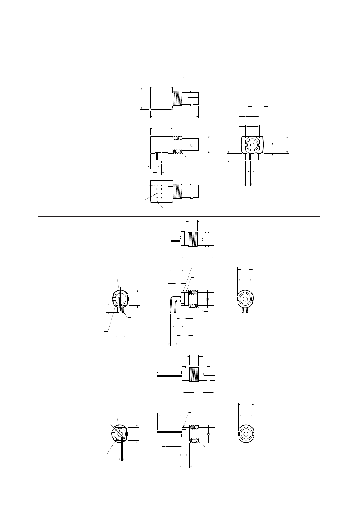
Mechanical Dimensions
HFBR-0400 FC Series
Mechanical Dimensions
HFBR-0400 SC Series
3.81
(0.15)
12.7
(0.50)
12.7
(0.50)
5.1
(0.20)
8
1
3
5
24
6
7
PIN NO. 1
INDICATOR
7.9
(0.31)
2.5
(0.10)
M8 x 0.75 6G
THREAD (METRIC)
2.5
(0.10)
3.6
(0.14)
19.6
(0.77)
10.2
(0.40)
Rx/Tx
COUNTRY OF
ORIGIN
hp YYWW
HFBR-X42X
HFBR-X4EX
28.65
(1.128)
15.95
(0.628)
10.0
(0.394)
12.7
(0.500)
Rx/Tx
COUNTRY OF
ORIGIN
hp YYWW
HFBR-X4EX
53
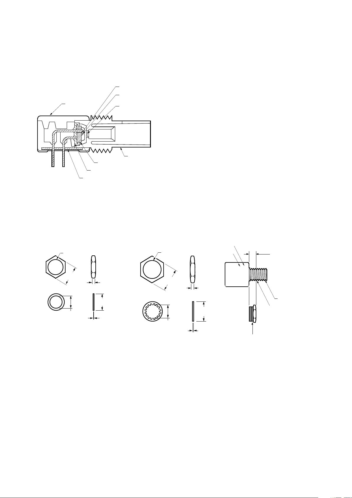
Figure 1. HFBR-0400 ST Series Cross-Sectional View.
Panel Mount Hardware
Port Cap Hardware
HFBR-4402: 500 SMA Port Caps
HFBR-4120: 500 ST Port Plugs (120 psi)
HFBR-4412: 500 FC Port Caps
HFBR-4417: 500 SC Port Plugs
HOUSING
CONNECTOR PORT
HEADER
EPOXY BACKFILL
PORT GROUNDING PATH INSERT
LED OR DETECTOR IC
LENS–SPHERE
(ON TRANSMITTERS ONLY)
LENS–WINDOW
7.87
(0.310)
TYP
DIA
0.14
(0.005)
1.65
(0.065)
1/4 – 36 UNEF –
2B THREAD
HEX-NUT
DIA
6.61
(0.260)
WASHER
7,87
(0.310)
14.27
(0.563)
TYP
DIA
10.41
(0.410)
MAX
DIA
0.46
(0.018)
1.65
(0.065)
3/8 – 32 UNEF2B THREAD
HEX-NUT
DIA
12.70
(0.50)
WASHER
HFBR-4401: for SMA Ports HFBR-4411: for ST Ports
(Each HFBR-4401 and HFBR-4411 kit consists of 100 nuts and 100 washers.)
3/8 - 32 UNEF - 2A THREADING
0.2 IN.
WALL
WASHER
NUT
1 THREAD AVAILABLE
Rx/Tx
COUNTRY OF
ORIGIN
hp YYWW
HFBR-X40X
DATE CODE
PART NUMBER
54
Options
In addition to the various port
styles available for the HFBR0400 series products, there are
also several extra options that
can be ordered. To order an
option, simply place the corresponding option number at the
end of the part number. For
instance, a metal-port option SMA
receiver would be HFBR-2406M.
You can add any number of
options in series at the end of a
part number. Please contact your
local sales office for further
information or browse HP’s fiber
optics home page at http://
www.hp.com/go/fiber
Option T (Threaded Port
Option)
• Allows ST style port components to be panel mounted.
• Compatible with all current
makes of ST multimode
connectors
• Mechanical dimensions are
compliant with MIL-STD83522/13
• Maximum wall thickness when
using nuts and washers from
the HFBR-4411 hardware kit is
2.8 mm (0.11 inch)
• Available on all ST ports
Option C (Conductive Port
Receiver Option)
• Designed to withstand electrostatic discharge (ESD) of 25kV
to the port
• Significantly reduces effect of
electromagnetic interference
(EMI) on receiver sensitivity
• Allows designer to separate the
signal and conductive port
grounds
• Recommended for use in noisy
environments
• Available on SMA and threaded
ST port style receivers only
Option M (Metal Port Option)
• Nickel plated aluminum connector receptacle
• Designed to withstand electrostatic discharge (ESD) of 15kV
to the port
• Significantly reduces effect of
electromagnetic interference
(EMI) on receiver sensitivity
• Allows designer to separate the
signal and metal port grounds
• Recommended for use in very
noisy environments
• Available on SMA, FC, ST, and
threaded ST ports
Option K (Kinked Lead
Option)
• Grounded outside 4 leads are
“kinked”
• Allows components to stay
anchored in the PCB during
wave solder and aqueous wash
processes
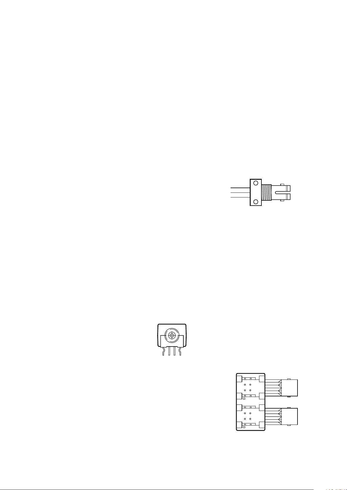
Options TA, TB, HA, HB
(Active Device Mount
Options)
(These options are unrelated to
the threaded port option T.)
• All metal, panel mountable
package with a 3 or 4 pin
receptacle end
• Available for HFBR-14X4, 24X2
and 24X6 components
• Choose from diamond or
square pinout, straight or bent
leads ADM Picture
• TA = Square pinout/straight
leads
TB = Square pinout/bent leads
HA = Diamond pinout/straight
leads
HB = Diamond pinout/bent
leads
Duplex Option
In addition to the standard
options, some HFBR-0400 series
products come in a duplex configuration with the transmitter on
the left and the receiver on the
right. This option was designed
for ergonomic and efficient
manufacturing. The following
part numbers are available in the
duplex option:
HFBR-5414 (Duplex ST)
HFBR-5414T (Duplex Threaded
ST)
HFBR-54E4 (Duplex SC)
45
36
27
36
27
18
45
18

55
Typical Link Data
HFBR-0400 Series
Description
The following technical data is
taken from 4 popular links using
the HFBR-0400 series: the 5 MBd
link, Ethernet 20 MBd link,
Token Ring 32 MBd link, and the
155 MBd link. The data given
corresponds to transceiver solutions combining the HFBR-0400
series components and various
recommended transceiver design
circuits using off-the-shelf
electrical components. This data
is meant to be regarded as an
example of typical link performance for a given design and does
not call out any link limitations.
Please refer to the appropriate
application note given for each
link to obtain more information.
5 MBd Link (HFBR-14XX/24X2)
Link Performance -40°C to +85°C unless otherwise specified
Parameter Symbol Min. Typ. Max. Units Conditions Reference
Optical Power Budget OPB
50
4.2 9.6 dB HFBR-14X4/24X2 Note 1
with 50/125 µm fiber NA = 0.2
Optical Power Budget OPB
62.5
8.0 15 dB HFBR-14X4/24X2 Note 1
with 62.5/125 µm fiber NA = 0.27
Optical Power Budget OPB
100
8.0 15 dB HFBR-14X2/24X2 Note 1
with 100/140 µm fiber NA = 0.30
Optical Power Budget OPB
200
12 20 dB HFBR-14X2/24X2 Note 1
with 200 µm fiber NA = 0.37
Date Rate Synchronous dc 5 MBd Note 2
Asynchronous dc 2.5 MBd Note 3,
Fig. 7
Propagation Delay t
PLH
72 ns TA = 25°C, Figs. 6, 7, 8
LOW to HIGH PR = -21 dBm Peak
Propagation Delay t
PHL
46 ns
HIGH to LOW
System Pulse Width t
PLH-tPHL
26 ns Fiber cable
Distortion length = 1 m
Bit Error Rate BER 10
-9
Data Rate <5 Bd
PR > -24 dBm Peak
Notes:
1. OPB at TA = -40 to 85°C, VCC = 5.0 V dc, I
F ON
= 60 mA. PR = -24 dBm peak.
2. Synchronous data rate limit is based on these assumptions: a) 50% duty factor modulation, e.g., Manchester I or BiPhase
Manchester II; b) continuous data; c) PLL Phase Lock Loop demodulation; d) TTL threshold.
3. Asynchronous data rate limit is based on these assumptions: a) NRZ data; b) arbitrary timing-no duty factor restriction; c) TTL
threshold.
 Loading...