

Page 1

DESIGNJET T790/T1300/Z5400ps
ePrinter series & T2300 eMFP series
Service manual
Page 2

For HP Internal Use Only
©Copyright Hewlett-Packard Company
2011
This document contains proprietary
information that is protected by copyright.
All rights are reserved. No part of this
document may be photocopied, reproduced,
or translated to another language without
the prior written consent of Hewlett-Packard
Company.
Edition, December 2013.
Page 3

Notices
Warranty
The information contained in this
document is subject to change without
notice.
Hewlett-Packard makes no
warranty of any kind with
regard to this material,
including, but not limited to,
the implied warranties of
merchantability and fitness for
a particular purpose.
Hewlett-Packard shall not be liable for
errors contained herein or for
incidental or consequential damages
in connection with the furnishing,
performance, or use of this material.
WARNING
The procedures described in this manual are
to be performed by HP-qualified service
personnel only.
Electrical Shock Hazard
Serious shock hazard leading to death or
injury may result if you do not take the
following precautions:
Ensure that the ac power outlet (mains)
●
has a protective earth (ground)
terminal.
Disconnect the product from the power
●
source prior to performing any
maintenance.
Prevent water or any other liquids from
●
running onto electrical components or
circuits, or through openings in the
enclosure.
Electrostatic Discharge
Refer to the beginning of Chapter 4
Introduction on page 272 of this manual,
for precautions you should take to prevent
damage to the product circuits from
electrostatic discharge.
WARNING
The Warning symbol calls attention to
a procedure, practice, or the like,
which, if not correctly performed or
adhered to, could result in personal
injury. Do not proceed beyond a
Warning symbol until the indicated
conditions are fully understood and
met.
CAUTION
The Caution symbol calls attention to
an operating procedure, practice, or
the like, which, if not correctly
performed or adhered to, could result
in damage to or destruction of part or
all of the product. Do not proceed
beyond a Caution symbol until the
indicated conditions are fully
understood and met.
Safety Symbols
General definitions of safety symbols are
given immediately after the table of
contents.
Content Management Department,
Barcelona Division,
Hewlett-Packard Espanola, S.A.
Avda. Graells, 501
08190 Sant Cugat del Valles
Spain
ENWW iii
Page 4

iv Notices ENWW
Page 5
Using this Manual
This Service Manual contains information necessary to test, calibrate, maintain and service the
following:
RTL PostScript
HP Designjet T790 24inch CR647A CR648A
HP Designjet T790 44inch CR649A CR650A
HP Designjet T1300 44inch CR651A CR652A
HP Designjet T2300 eMFP
44inch
HP Designjet T790 24inch
Rev.B
HP Designjet T790 44inch
Rev.B
HP Designjet T1300 44inch
Rev.B
HP Designjet T2300 eMFP
44inch Rev.B
HP Designjet Z5400ps 44inch - E1L21A
HP Designjet Z5400ps 44inch
Rev.B
CN727A CN728A
- CR648B
- CR650B
- CR652B
- CN728B
- E1L21B
When information is only applicable to a specific product, the text will indicate which product it is
applicable to. There are three main areas where this might occur, and at each occurrence an icon will
also be shown:
HP Designjet T2300 Printer
series
HP Designjet T790/T1300/Z5400ps
Printer series
Web Enabled
For information about using these products, refer to the corresponding User and Quick Reference
Guides.
Readership
The procedures described in this Service Manual are to be performed by HP Certified service personnel
only.
Part Numbers
ENWW v
Page 6

Part Numbers for product service parts are located in Chapter 7 Parts and Diagrams on page 239.
vi Using this Manual ENWW
Page 7

Table of contents
1 Troubleshooting ................................................................................................................ 1
Using the Touch Control Panel (MFP only) ................................................................................... 2
Using the Touch Control Panel ................................................................................................... 4
Service Key Combinations ......................................................................................................... 6
Product Troubleshooting trees (MFP) ........................................................................................... 7
Paper-handling troubleshooting ................................................................................................ 15
Ink-supplies troubleshooting ..................................................................................................... 16
Print Quality .......................................................................................................................... 37
The Service Image Quality Diagnostic Print ............................................................................... 38
Reading the Diagnostic Print Results .......................................................................................... 40
Advanced Diagnostic Prints ..................................................................................................... 45
Reading the Advanced diagnostic Print Results ........................................................................... 47
Troubleshooting Print Quality Problems ..................................................................................... 53
Connectivity troubleshooting .................................................................................................... 66
2 System Error Codes ......................................................................................................... 71
Introduction ........................................................................................................................... 71
Product logs .......................................................................................................................... 72
What to do if the Touch Control Panel is blank .......................................................................... 72
Troubleshooting system Error 08:11 using LEDs of the Formatter .................................................. 76
Continuable and Non-Continuable Error Codes ......................................................................... 77
System Error Code Brief Descriptions ........................................................................................ 77
System Error Codes—Full Descriptions ...................................................................................... 80
Appendix A: How to troubleshoot SE 79:04 ............................................................................ 109
Appendix B: Emergency firmware upgrade with USB flash drive ................................................ 121
Appendix C: Obtaining the product log and the diagnostics package ........................................ 122
Appendix D: How to check the display list memory for an HP-GL/2 job ...................................... 126
3 Diagnostics Menu ......................................................................................................... 129
Introduction ......................................................................................................................... 129
Diagnostic Tests and Utilities .................................................................................................. 131
ENWW vii
Page 8

4 Service Menu ................................................................................................................ 173
Introduction ......................................................................................................................... 173
Service Utilities .................................................................................................................... 173
Service Calibrations ............................................................................................................. 214
5 Parts and Diagrams ...................................................................................................... 239
Introduction ......................................................................................................................... 240
Product Support ................................................................................................................... 241
Center Covers Front (1 of 3) .................................................................................................. 242
Center Covers Front (2 of 3) .................................................................................................. 243
Center Covers Front (3 of 3) .................................................................................................. 244
Roll Covers .......................................................................................................................... 245
Center Covers (Rear) ............................................................................................................ 246
Right Cover ......................................................................................................................... 247
Left Cover ........................................................................................................................... 248
Right Hand Assemblies ......................................................................................................... 249
Left Hand Assemblies ............................................................................................................ 250
Carriage Assembly ............................................................................................................... 252
Scan-Axis Assemblies ........................................................................................................... 253
Paper Path Assemblies (Front) ................................................................................................ 254
Paper Path Assemblies (Rear) ................................................................................................. 255
Roll Supports ....................................................................................................................... 256
Scanner Parts (1 of 3) ........................................................................................................... 258
Scanner Parts (2 of 3) ........................................................................................................... 259
Scanner Parts (3 of 3) ........................................................................................................... 260
Tools 1 ............................................................................................................................... 261
Tools 2 ............................................................................................................................... 262
Miscellaneous Parts .............................................................................................................. 263
6 Removal and Installation .............................................................................................. 269
Introduction ......................................................................................................................... 272
Customer Self Repair parts .................................................................................................... 275
Service Calibration Guide to Removal and Installation .............................................................. 277
Belt Assembly ...................................................................................................................... 279
Bin Assembly ....................................................................................................................... 280
Bi-stable Springs .................................................................................................................. 283
Bumpers, Left and Right ......................................................................................................... 289
Engine Cables Kit ................................................................................................................ 293
Interconnect Cables Kit ......................................................................................................... 306
Carriage and Cutter Assembly ............................................................................................... 316
viii ENWW
Page 9

Carriage Bushing, Rear ........................................................................................................ 325
Carriage Cover and Carriage Latch ....................................................................................... 327
Carriage Rail Oiler .............................................................................................................. 332
Carriage PCA ...................................................................................................................... 334
Cleanout ............................................................................................................................. 339
Center Support .................................................................................................................... 341
Converger ........................................................................................................................... 345
Scanner Piston Gas (MFP only) .............................................................................................. 347
Scanner Bumper (MFP only) ................................................................................................... 350
Right Collar Cover (MFP only) ................................................................................................ 353
Front Cover ......................................................................................................................... 360
Front Top Cover Assembly (MFP only) ..................................................................................... 361
Front Top Cover ................................................................................................................... 363
Drop Detector ...................................................................................................................... 366
Aerosol Fan Assembly .......................................................................................................... 368
EE Box ................................................................................................................................ 370
Encoder Disk and Encoder Sensor .......................................................................................... 375
Encoder Strip ....................................................................................................................... 377
Encoder Strip, spring and attachment nut ................................................................................ 378
Formatter ............................................................................................................................ 381
Freewheel Assembly ............................................................................................................. 383
Right Front Trim .................................................................................................................... 386
Full Bleed Foam ................................................................................................................... 388
Hard Disk Drive ................................................................................................................... 389
Left Ink Cartridge Door ......................................................................................................... 391
Right Ink Cartridge Door ....................................................................................................... 393
Left Ink Supply Station ........................................................................................................... 395
Ink Supply Tubes & Trailing Cable .......................................................................................... 400
Ink Supply Tubes Support Rail ................................................................................................ 409
Interconnect PCA ................................................................................................................. 411
Left Collar Cover (MFP only) .................................................................................................. 413
Left Cover ........................................................................................................................... 414
Left Front Trim ...................................................................................................................... 418
Left Scanner Cover (MFP only) ............................................................................................... 420
Scanner Latch and Hook Assembly (MFP only) ......................................................................... 422
Line Sensor .......................................................................................................................... 424
Media Advance Drive .......................................................................................................... 430
Media Lever ........................................................................................................................ 438
Media Lever Position Sensor .................................................................................................. 440
Media Output Assembly ....................................................................................................... 442
Out-of-paper Sensor ............................................................................................................. 444
ENWW ix
Page 10

Left Panel ............................................................................................................................ 447
Pen to Paper Space (PPS) Solenoid ......................................................................................... 449
Pinch Arm Assembly ............................................................................................................. 451
Pinchwheel Assembly ........................................................................................................... 454
Print Zone Overdrive ............................................................................................................ 462
Power Supply Unit ................................................................................................................ 466
Real-time Clock Battery ......................................................................................................... 468
Rear Cover (MFP only) .......................................................................................................... 469
Rear Cover .......................................................................................................................... 472
Rear Deflectors .................................................................................................................... 473
Right Cover ......................................................................................................................... 475
Right Scanner Cover (MFP only) ............................................................................................. 479
Roll Cover Bumpers, Lower .................................................................................................... 482
Roll Cover, Lower ................................................................................................................. 485
Roll Cover, Upper ................................................................................................................ 489
Left Roll Guide ..................................................................................................................... 491
Right Roll Guide ................................................................................................................... 492
Roll Support, Lower Left ......................................................................................................... 493
Roll Support, Lower Right ...................................................................................................... 495
Roll Support Sensor, Lower Left .............................................................................................. 497
Roll Support Sensor, Upper Left .............................................................................................. 498
Roll Support, Upper Left ........................................................................................................ 499
Roll Support, Upper Right ...................................................................................................... 501
Scan-axis Motor ................................................................................................................... 503
Service Station ..................................................................................................................... 507
Single-sheet Sensor ............................................................................................................... 512
Spindle ............................................................................................................................... 514
Spittoon, Left ....................................................................................................................... 515
Starwheel Assembly ............................................................................................................. 517
Starwheel Lifter, Left .............................................................................................................. 519
Starwheel Lifter, Right ........................................................................................................... 521
Starwheel Motor .................................................................................................................. 525
Wall Spacers ...................................................................................................................... 527
Scanner Position Sensor (MFP only) ........................................................................................ 530
Torsion Damper (MFP only) ................................................................................................... 535
CIS Element (MFP only) ......................................................................................................... 538
Scanner Exit Media Sensors (MFP only) .................................................................................. 539
Scanner Entry Media Sensors (MFP only) ................................................................................ 540
Pressure Rollers (MFP only) .................................................................................................... 541
Scanner Controller Board (MFP only) ...................................................................................... 542
Scanner Motor Assembly (MFP only) ...................................................................................... 544
x ENWW
Page 11

Taco Sensor (MFP only) ........................................................................................................ 545
Touch Control Panel ............................................................................................................. 547
Window ............................................................................................................................. 551
Window Position Sensor ....................................................................................................... 555
7 Preventive Maintenance ............................................................................................... 557
Preventive Maintenance ........................................................................................................ 557
Preventive Maintenance Kits .................................................................................................. 565
Appendix A CSR Installation Flyers .................................................................................. 569
Cutter assembly ................................................................................................................... 570
Freewheel assembly ............................................................................................................. 572
Freewheel assembly (screwdriver) .......................................................................................... 574
Left side panel (T1200) ......................................................................................................... 576
Pinch arm assembly .............................................................................................................. 578
Pinch arm assembly (screwdriver) ........................................................................................... 580
Roll cover upper bumpers ...................................................................................................... 582
Roll cover upper bumpers (screwdriver) ................................................................................... 584
Foot Extension ..................................................................................................................... 586
Front Deflector ..................................................................................................................... 587
Rear Deflector Mylar ............................................................................................................ 589
Glass Plate .......................................................................................................................... 591
Latch Handle Cover .............................................................................................................. 593
ENWW xi
Page 12

xii ENWW
Page 13

1 Troubleshooting
Using the Touch Control Panel (MFP only)
●
Using the Touch Control Panel
●
Service Key Combinations
●
Product Troubleshooting trees (MFP)
●
Paper-handling troubleshooting
●
Ink-supplies troubleshooting
●
Print Quality
●
The Service Image Quality Diagnostic Print
●
Reading the Diagnostic Print Results
●
Advanced Diagnostic Prints
●
Reading the Advanced diagnostic Print Results
●
Troubleshooting Print Quality Problems
●
Connectivity troubleshooting
●
ENWW 1
Page 14
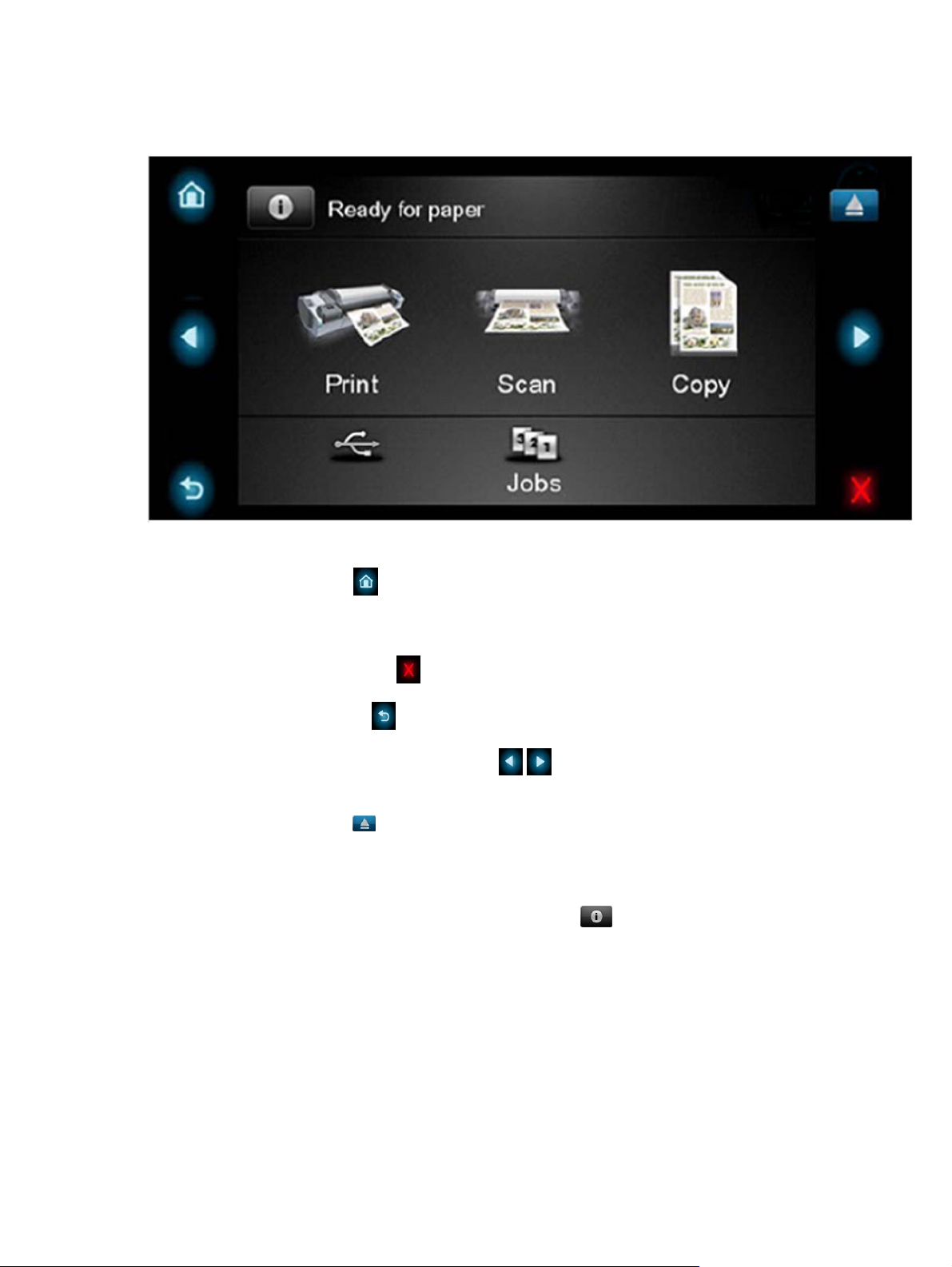
Using the Touch Control Panel (MFP only)
The external frame of the Touch Control Panel contains the following elements:
●
The Home LED (top-left)
same Home Screen is displayed. When pressed for more than 4 seconds, the Accessibility Home
Screen is displayed.
is used to return to the Home Screen. When clicked only once, this
●
The Cancel LED (bottom right)
●
The Back LED (bottom left)
●
The Arrow LEDs (in the middle of each side)
directions.
The Eject LED (top-right)
●
The internal part of the Touch Control Panel is the Home Screen and this is divided into three main
areas:
●
The upper area is for the Product Information (left icon)
alerts (in text) you can press the most critical alert in the home screen and the others (less critical)
will be shown.
The main menu of the product is accessed by clicking on the Product Information icon and then
selecting the last tab (at the right side)
The middle area is used to place the three icons for the main work flows of the product, which
●
are: Print, Scan and Copy.
The lower area of the Home Screen is reserved for the contents area. The contents area will
●
contain all the functionality related with printing content, for example in the Job Queue.
is used to cancel any action, when it is active.
is to go back to the previous screen, when it is active.
enables the user to navigate in both
enables the user to stop the USB connection.
and for displaying high priority
2 Chapter 1 Troubleshooting ENWW
Page 15

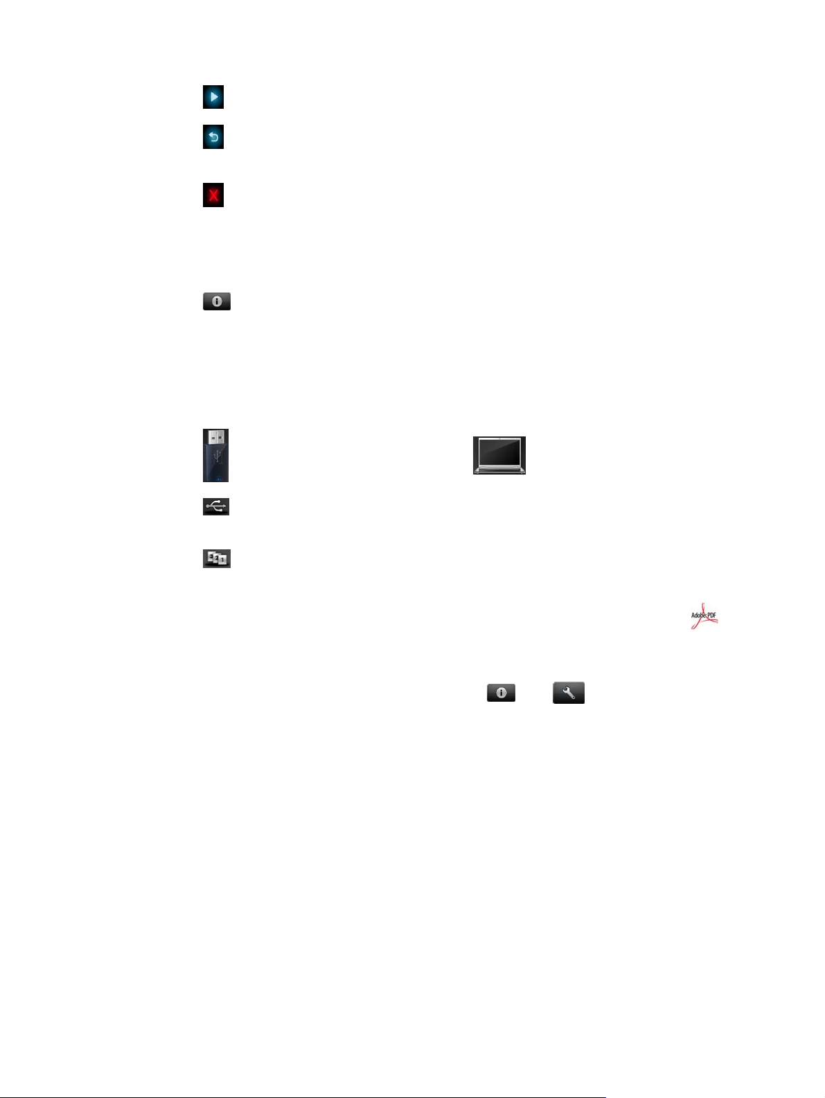
When a USB drive is inserted, a USB icon will also be displayed to the left of this area, and
when a Postscript/PDF job is being printed an Adobe logo
bottom right area
will display in the
ENWW
Using the Touch Control Panel (MFP only)
3
Page 16

Using the Touch Control Panel
The Touch Control Panel is located on the front right of the printer. It gives you complete control of your
printer: from here you can print, view information about the printer, change printer settings, perform
calibrations and tests, and so on. The Touch Control Panel also displays alerts (warning and error
messages) when needed.
1. A Hi-Speed USB host port, intended for connecting a USB flash drive, which can provide files to
be printed. When a USB flash drive is inserted, a USB icon
Panel's home screen.
2. The Touch Control Panel itself: a touch-sensitive screen with a graphical user interface.
is displayed on the Touch Control
3. The Power key, with which you can turn the printer on or off. The key is illuminated when the
printer is on. It flashes when the printer is in transition between on and off.
The Touch Control Panel has a large central area to display dynamic information and icons. On the left
and right sides you can see up to six fixed icons at different times. Normally they are not all displayed
at the same time.
Left and right fixed icons
●
Press
to return to the home screen.
●
Press
●
Press
4 Chapter 1 Troubleshooting ENWW
to view help about the current screen.
to go to the previous item.
Page 17
●
Press
●
Press
current screen.
●
Press
Home screen dynamic icons
The following items are displayed only on the home screen.
●
Press
as loading paper or replacing ink supplies. A smaller warning icon appears if there are actions
that need to be performed.
To the right of the above button is a message showing the printer status or the most important
●
current alert. Press this message to see a list of all current alerts, with an icon indicating the
severity of each alert.
●
Press
to go to the next item.
to go back to the previous screen. This does not discard any changes made in the
to cancel the current process.
to view information about printer status, change printer settings, or initiate actions such
to print a file from a USB flash drive, or to print from a computer.
●
Press
more USB flash drives are inserted.
●
Press
on hold.
●
While a PostScript or PDF job is printing (PostScript printers only), the Adobe PDF icon
displayed; pressing it has no effect.
If the printer is left idle for some time, it goes into sleep mode and switches off the front-panel display.
To change the time that elapses before sleep mode, press
panel options > Sleep mode wait time. You can set a time between 1 and 240 minutes.
The printer wakes from sleep mode and switches on the front-panel display whenever there is some
external interaction with it.
Information about specific uses of the Touch Control Panel can be found throughout this guide.
to view information about the USB flash drive(s). This icon appears only when one or
to view and manage the job queue. A smaller warning icon appears if there are jobs
is
, then , then Setup > Front
ENWW
Using the Touch Control Panel
5
Page 18

Service Key Combinations
Table 1-1 Service Key Combinations
Label Description
Diagnostic mode 1. With the product turned off, press the Power Key
Service menu (Service Engineers only) With the product is powered on, access main menu – service
Service menu (for users) With the product powered on, access main menu – service
2. When the magic frame LEDs become active, select by
touching one of the following sequences:
CANCEL + HOME + EJECT: hp-service-1: For The
●
Onsite Engineer
CANCEL + BACK + EJECT: hp-service-2: For call
●
center remote support
The LEDs in the frame will blink a response to confirm the
selected sequence.
menu.
Password is 3174
For tools that require another password, this is 5494
menu.
Password is 3174. There is an icon in front of the option,
indicating that the tool is protected (which requires a service
password).
6 Chapter 1 Troubleshooting ENWW
Page 19

Product Troubleshooting trees (MFP)
Us the following troubleshooting trees to troubleshoot issues with the MFP in the first instance.
ENWW
Product Troubleshooting trees (MFP)
7
Page 20
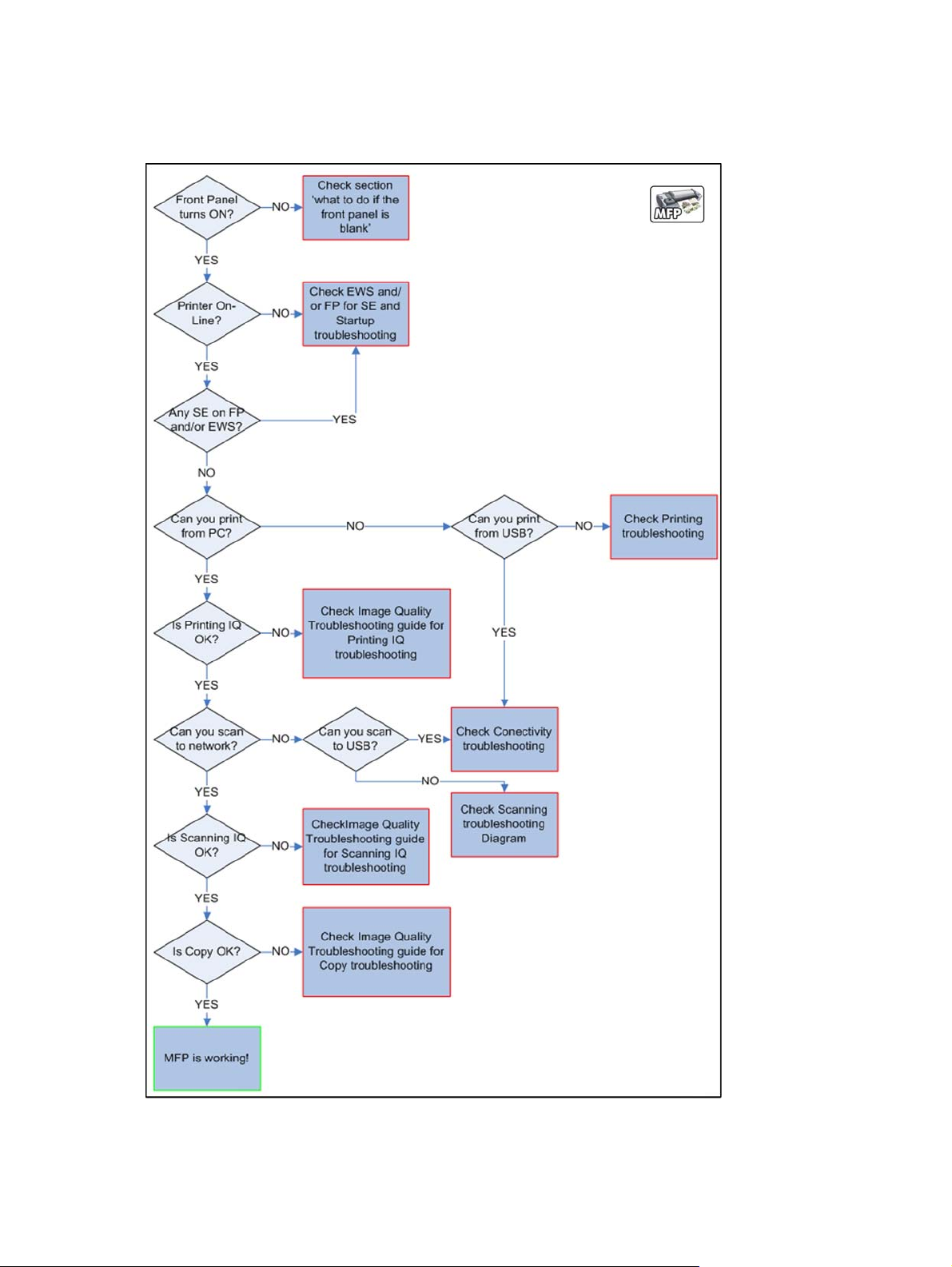
Product Troubleshooting Tree
Figure 1-1 Troubleshooting
8 Chapter 1 Troubleshooting ENWW
Page 21
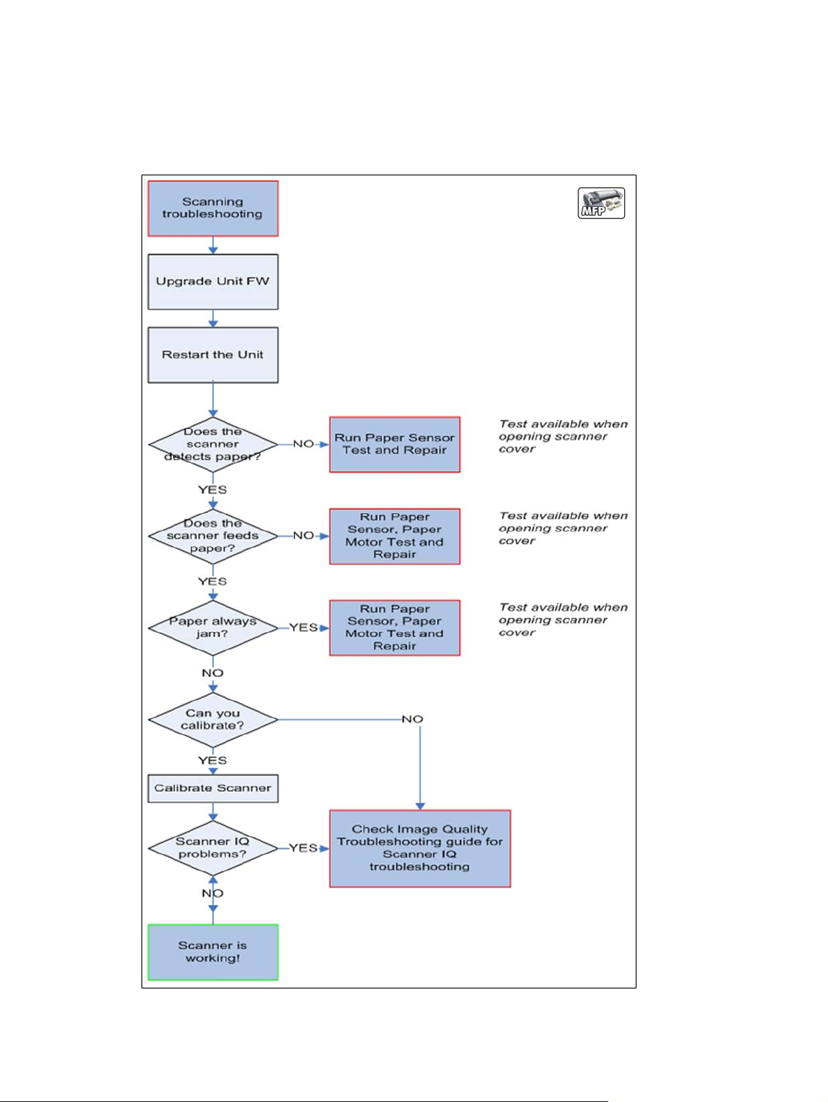
Scanner Troubleshooting Tree
Use this tree to troubleshoot the scanner in the MFP.
Figure 1-2 Scanner Troubleshooting
ENWW
Product Troubleshooting trees (MFP)
9
Page 22

Scanner CIS Troubleshooting
Use this tree to troubleshoot the CIS of the scanner in the MFP.
Figure 1-3 Scanner Troubleshooting
Troubleshooting system error codes
System Error Codes on page 71 contains a list of system error codes and their respective descriptions
and recommended corrective actions. Try only one recommended action at a time and check whether
the error code has disappeared.
If you have an error code which is not documented in this Service Manual or you have an error which
you cannot resolve, then report the error to the HP Response Center or the nearest HP Support Office.
When reporting the error, have the information ready, refer to
on page 71:
10 Chapter 1 Troubleshooting ENWW
Reporting a system error to HP support
Page 23

Performing a service test on a failed assembly
If possible, always perform a Service Test on the component/assembly that you are about to replace,
just to make sure that is the component/assembly that has failed.
Shown below is a list of the Service tests and the component(s) tested:
Scan Axis Test
●
Star Wheel Lifter
◦
PRS
◦
Scan Axis Servosystem
◦
Cutter
◦
Paper Drive Test
●
Components of the Paper Axis Subsystem
◦
Electronics Module Test
●
Formatter
◦
Carriage assembly test
●
Carriage Assembly
◦
Sensors Test
●
Scanner Position Sensor (MFP only)
◦
Media Lever Position sensor
◦
Media sensor
◦
Upper or lower roll cover sensor
◦
Single-sheet sensor
◦
Rewinder test
●
Right Roll Support.
◦
Ink Delivery System Test
●
Ink Supply Station
◦
Ink supplies
◦
Service Station test
●
Service Station.
◦
ENWW
Primer Motor
◦
Product Troubleshooting trees (MFP)
11
Page 24

NOTE: If the test on that component/assembly passes, you should not replace it.
For information on the Service Tests and how to use them see
Diagnostics Menu on page 129.
Performing the necessary service calibrations
Is the product calibrated correctly after replacing a component? For information on the Service
Calibrations and how to use them see
NOTE: Remember that certain Calibrations are required even if an Assembly has been disassembled
to gain access to another Assembly or Component.
Service Menu on page 173.
Solving scan/print-quality problems
Refer to the Image Quality Troubleshooting Guide (in the EWS-Support Tab or in the CD).
The Touch Control Panel is blank
See What to do if the Touch Control Panel is blank on page 72.
The product does not power on
See What to do if the Touch Control Panel is blank on page 72.
The product continuously rejects printheads
Clean the flex contacts on the Printhead and in the Carriage Assembly using the Carriage
▲
Interconnect Wiper and try again.
Cover sensors are not working
1. Perform the Sensors Test. See Sensors Test on page 149.
2. Check that the cable for the faulty sensor is not damaged and is connected correctly.
3. Replace the faulty Sensor.
The line sensor has problems detecting paper
1. Check the type of paper that is being used since the Line sensor may have problems detecting
transparent paper or some types of Non-HP paper. Try loading white HP paper in to the product
and check that the Line sensor detects it.
2. The Line Sensor is not calibrated correctly. Perform the Line Sensor Calibration. See
Calibration on page 228.
3. The Line Sensor is damaged or faulty. Replace the Line Sensor. See
Line Sensor
Line Sensor on page 424.
12 Chapter 1 Troubleshooting ENWW
Page 25
Troubleshooting Printer paper jams and printhead crashes
The failure modes "paper jam" and "head crash" are grouped together because in many cases a
paper jam causes the paper to lift up into the Carriage path and cause a Printhead crash, thus causing
many paper jam failures to be reported as head crashes.
1. Did the paper jam occur when loading paper?
If the client has had paper jams, it is common for pieces of paper to get stuck in the paper
●
path. Clear the paper path.
NOTE: When clearing a paper jam, sometimes paper is stuck in the paper path. To clear this,
you must lift the Media Lever and insert thicker paper into the paper path to push out the paper
that is still stuck there.
2. Is the customer using non-HP paper?
The use of non-HP paper can easily be the cause of paper jams and head crashes (especially
●
head crashes because HP paper is specially formulated to avoid cockle, one of the primary
causes of head crashes). If the paper is not HP approved, advise the customer to use HP
paper and check to see whether the problem is now solved.
Troubleshooting Scanner paper jams (MFP only)
1. If while feeding paper into the Scanner a jam occurs, use the eject button on the Touch
Control Panel to clear the jam.
2. Unlatch the CIS Cover.
ENWW
Product Troubleshooting trees (MFP)
13
Page 26

3. Open the CIS and clear the area of any paper.
The basket was damaged during the product setup
1. There are three plastic parts that could break during product installation and need replacing.
2. Check the parts table and graphics in Parts and Diagrams to identify what service parts you must
order. See
Product Support on page 241.
3. Replace the component. See
Bin Assembly on page 280.
14 Chapter 1 Troubleshooting ENWW
Page 27

Paper-handling troubleshooting
Roll paper The Touch Control Panel of the product indicates that paper is misaligned or incorrectly positioned
The roll may be loaded the wrong way. The paper should load over the roll toward you.
●
Check that the paper is correctly loaded onto the spindle.
●
The paper may be loaded at an angle. The right-hand edge must be aligned with the blue line on the
●
Print Platen.
Check that the Right Roll Support is properly attached and screwed to the product.
●
The Rewinder, located on the Right Roll Support, should maintain proper back tension. If the Right Roll
●
Support is misaligned or not properly attached to the product, the Rewinder will not function properly.
Sheet paper
To further diagnose problems with the Rewinder, see
●
If the customer is experiencing problems with paper jams, check that the Overdrive is not obstructed by
●
paper or that the Turn Drive Roller Service Utility is being used. See
While attempting to load roll media, if the Touch Control Panel prompts you to remove paper, although
●
no paper is loaded, calibrate the sheet sensor, refer to
The sheet must be loaded with the right-hand edge against the white line on the upper roll cover.
●
The paper may be crumpled or warped or may have irregular edges.
●
If the printer incorrectly detects the presence of a sheet of paper, perform the Calibrate Sheet Sensor,
●
refer to
Calibrate Sheet Sensor on page 232.
If hand-cut paper is used, the edges may not form a right-angle or they may be rough. If possible,
●
hand-cut paper should not be used. Only purchased sheet paper should be used in the product.
If you have problems with paper jams, check that the Overdrive is not obstructed by bits of paper or
●
using the Turn Drive Roller Service Utility. See
When attempting to load sheet paper from Front Panel, if the printer displays a media skew message
●
repeatedly, and sheet cannot be loaded, calibrate sheet sensor. refer to
on page 232
Rewinder Test on page 151.
Turn Drive Roller on page 177
Calibrate Sheet Sensor on page 232
Turn Drive Roller on page 177.
Calibrate Sheet Sensor
ENWW
Paper-handling troubleshooting
15
Page 28

Ink-supplies troubleshooting
Introduction to ink supplies
●
Ink cartridge levels, information and replacement
●
Printhead information, replacement and alignment
●
Ink cartridge and printhead status messages
●
Solving ink-supply problems
●
Maintaining and cleaning the printheads
●
Introduction to ink supplies
Introduction to ink supplies
What are ink supplies?
For each of the ink colors used in the product, there are two components, the Printhead and Ink
Cartridge. These components are called Ink Supplies.
Ink cartridges
The product's six Ink Cartridges provide matte black, magenta, yeloow, cyan, gray and photo black ink
to the Printheads. The color Ink Cartridges supplied with the product have a capacity of 69ml but
optional 130 ml are also available.
All these Ink cartridges are physically the same size. Only the internal capacity varies.
16 Chapter 1 Troubleshooting ENWW
Page 29
The Ink Cartridges for the T product series require no maintenance or cleaning. As long as each Ink
Cartridge is inserted correctly into its slot, the ink will flow to the Printheads. Because the Printheads
control the amount of ink transferred to the page, you will continue to see high-quality printing results
even when the ink levels are getting low.
The Touch Control Panel displays the status of the Ink Cartridge. Using the Touch Control Panel,
detailed information can be checked on the Ink Cartridges.
Table 1-2 Available Ink Cartridges
Ink cartridge Product Model Part number
HP 72 69 ml Photo Black Ink Cartridge T series models C9397A
HP 72 69 ml Cyan Ink Cartridge T series models C9398A
HP 72 69 ml Magenta Ink Cartridge T series models C9399A
HP 72 69 ml Yellow Ink Cartridge T series models C9400A
HP 72 69 ml Gray Ink Cartridge T series models C9401A
HP 72 130 ml Matte Black Ink Cartridge T series models C9403A
HP 72 130 ml Photo Black Ink Cartridge T series models C9370A
HP 72 130 ml Cyan Ink Cartridge T series models C9371A
ENWW
HP 72 130 ml Magenta Ink Cartridge T series models C9372A
HP 72 130 ml Yellow Ink Cartridge T series models C9373A
HP 72 130 ml Gray Ink Cartridge T series models C9374A
HP 726 300 ml Matte Black Ink Cartridge T1300 series only CH575A
HP 70 Matte Black 130 ml Ink Cartridge Z5400 series models C9448A
HP 70 Photo Black 130 ml Ink Cartridge Z5400 series models C9449A
HP 70 Light Gray 130 ml Ink Cartridge Z5400 series models C9451A
HP 70 Cyan 130 ml Ink Cartridge Z5400 series models C9452A
HP 70 Magenta 130 ml Ink Cartridge Z5400 series models C9453A
HP 70 Yellow 130 ml Ink Cartridge Z5400 series models C9454A
Ink-supplies troubleshooting
17
Page 30
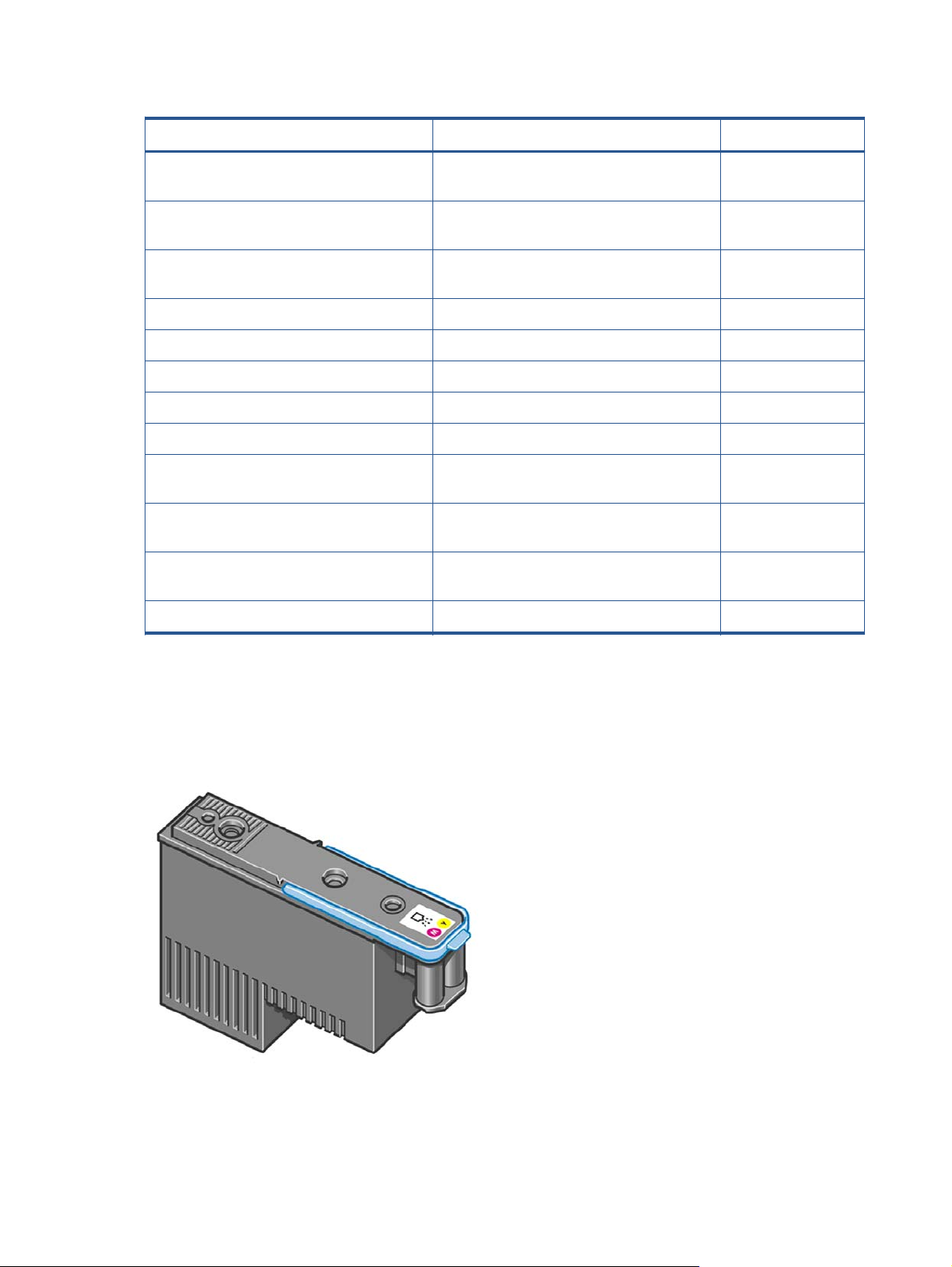
Table 1-2 Available Ink Cartridges (continued)
Ink cartridge Product Model Part number
HP 70 Matte Black 130 ml Ink Cartridge Twin
Pack
HP 70 Photo Black 130 ml Ink Cartridge Twin
Pack
HP 70 Light Gray 130 ml Ink Cartridge Twin
Pack
HP 70 Cyan 130 ml Ink Cartridge Twin Pack Z5400 series models CB343A
HP 70 Magenta 130 ml Ink Cartridge Twin Pack Z5400 series models CB344A
HP 70 Yellow 130 ml Ink Cartridge Twin Pack Z5400 series models CB345A
HP 772 300 ml Magenta Designjet Ink Cartridge Z5400 series models CN629A
HP 772 300 ml Yellow Designjet Ink Cartridge Z5400 series models CN630A
HP 772 300 ml Photo Black Designjet Ink
Cartridge
HP 772 300 ml Light Gray Designjet Ink
Cartridge
HP 772 300 ml Matte Black Designjet Ink
Cartridge
HP 772 300 ml Cyan Designjet Ink Cartridge Z5400 series models CN636A
Z5400 series models CB339A
Z5400 series models CB340A
Z5400 series models CB342A
Z5400 series models CN633A
Z5400 series models CN634A
Z5400 series models CN635A
Printheads
The Printheads are extremely durable and do not need to be replaced every time an Ink Cartridge is
replaced. They are independent of the Ink Cartridges and will continue giving excellent image-quality
results even if the Ink Cartridges are low on ink.
18 Chapter 1 Troubleshooting ENWW
Page 31

Table 1-3 Available Printheads
Product Model Part number
HP 72 Gray & Photo Black Printhead T series models C9380A
HP 72 Magenta & Cyan Printhead C9383A
HP 72 Matte Black & Yellow Printhead C9384A
HP 70 Matte Black and Cyan Printhead Z5400 series models C9404A
HP 70 Magenta and Yellow Printhead C9406A
HP 70 Photo Black and Light Gray Printhead C9407A
General information about the ink supplies
For optimum results from the product and modular ink delivery system always follow these guidelines
when handling the ink supplies:
Always install the Ink Cartridges and Printheads before the expiration date, which is on the
●
packaging.
Install Ink Cartridges and Printheads in their color-coded slots.
●
Follow the instructions on the Touch Control Panel of the product during installation.
●
Avoid unnecessary removal of the Ink Cartridges and Printheads.
●
When turning off the product always use the Power button on the Touch Control Panel. The
●
Printheads are then stored correctly which prevents them from drying out.
The Ink Cartridges should never be removed while the product is printing. They should only be
●
removed when the product is ready for you to replace them. The Touch Control Panel will guide
you through the removal and installation procedure.
General precautions when handling ink supplies
Use the following precautions when handling Ink Supplies:
NOTE: Do not touch, wipe or attempt to clean the printhead nozzles. This can damage the printhead.
Handle the ink supplies with care. In particular the Printhead, which is a high precision device and
●
must be handled carefully.
Do not touch the Printhead nozzles.
●
Do not put the Printhead down on the nozzles.
●
Do not be rough when handling the Printheads. Always set them down gently
●
ENWW
Do not drop the Printheads.
●
Proper handling will assure optimum performance throughout the Printhead life.
●
Ink-supplies troubleshooting
19
Page 32

Do not touch the end of the Ink Cartridge which is inserted into the product as there may be a
●
small amount of ink on the connection.
Avoid storing partially used Ink Cartridges on their ends.
●
When should you replace the ink supplies?
When to change the ink supplies is mostly determined by you with guidance from the Touch Control
Panel. In conjunction with the messages displayed in the Touch Control Panel and the message
explanations in this chapter, you will be able to choose for yourself when is the right time to change the
ink supplies.
The product will also display the ink level and will tell you when the ink supply is low on ink. This
means you have constantly updated information about the ink supplies.
Ink cartridge levels, information and replacement
Ink cartridge levels and information
The Touch Control Panel displays Ink Levels shown as level bars. These bars represent how much ink is
remaining in the Ink Cartridges: as ink is used up the bars get shorter in length. To view the ink levels
perform the following steps:
1.
Press on the Information icon
.
2. Press on the Ink Menu icon. Each of the Ink Cartridges is displayed as a bar indicating the level of
ink remaining.
3. To get further information of an Ink Cartridge, press on the corresponding bar that you want to
view.
The information supplied is:
20 Chapter 1 Troubleshooting ENWW
Page 33

The current status of the Ink Cartridge.
●
The current ink level of the ink cartridge in milliliters.
●
Original capacity of the ink cartridge in milliliters.
●
The make of the Ink Cartridge (HP no.72 is recommended).
●
The product name of the Ink Cartridge.
●
The product number of the Ink Cartridge.
●
The serial number of the Ink Cartridge.
●
The Expiration Date of the ink cartridge.
●
The current warranty status of the Ink Cartridge.
●
The manufacturer of the Ink Cartridge (HP is recommended).
●
The product consumes more gray ink than M, C, or Y
This is not a problem, and no action should be taken to “correct” this attribute of the product.
In general the higher frequency of change is because Matte Black ink is the one that is used for lines
and black objects in technical papers (bond, coated, HW coated, natural tracing paper, etc.), which
are the types of contents that are more commonly printed with this type of product.
About gray ink
The T Series products are the first HP Designjet technical products to include Gray ink. One thing that
users may notice is that Gray ink is used in higher quantities than Cyan, Magenta and Yellow inks. This
happens because of the following reasons:
1. Gray areas (which are very typical in technical drawings) can now be printed by using only Gray
ink. In the past, these areas had to be printed by combining Cyan, Magenta and Yellow inks. This
means that Gray ink is used more frequently than the rest of the inks (C, M, Y) which are now
used less frequently, so the difference in consumption is noticeable. However overall the T Series
products will actually need to use in total less ink to print gray areas than previous Designjet
products.
2. Soft colors can now be printed by combining C, M and Y inks with Gray. The addition of Gray
ink softens the color, improving transition areas. It also allows printing soft colors by using less C,
M and Y. These two types of contents are very typical and make the consumption of Gray to
increase and the consumption of C, M and Y to decrease.
Conclusion
However, no matter the combination of inks that are used, when the total cc’s of ink are added up, the
T Series products will always have a lower ink consumption than the HP Designjet 500, 800 and 1000
series for equivalent contents with equivalent levels of print quality.
Changing an Ink Cartridge
ENWW
There are two occasions when you need to remove an ink cartridge:
Ink-supplies troubleshooting
21
Page 34

The ink cartridge is very low and you want to replace it with a full cartridge for unattended
●
printing (you can use up the remaining ink in the first cartridge at a more convenient time).
The ink cartridge is empty or faulty, and you must replace it to continue printing.
●
NOTE: Do not try to remove an ink cartridge while printing. Remove an ink cartridge only if you are
ready to insert another one.
Make sure the product wheels are locked (the brake lever is pressed down) to prevent the product from
moving.
To change an ink cartridge there are two methods, the first is shown below by using the ink tab, the
second method is to access the main menu option (refer to the User's Guide for further details).
1. Press on the Information icon.
2. Press on the Ink Menu icon and the following screen is displayed.
Press on the Replace ink cartridge tab
3. The following screen is displayed, press OK to continue.
4. Open the relevant Ink Cartridge cover for the Ink Cartridge you want to replace.
22 Chapter 1 Troubleshooting ENWW
Page 35

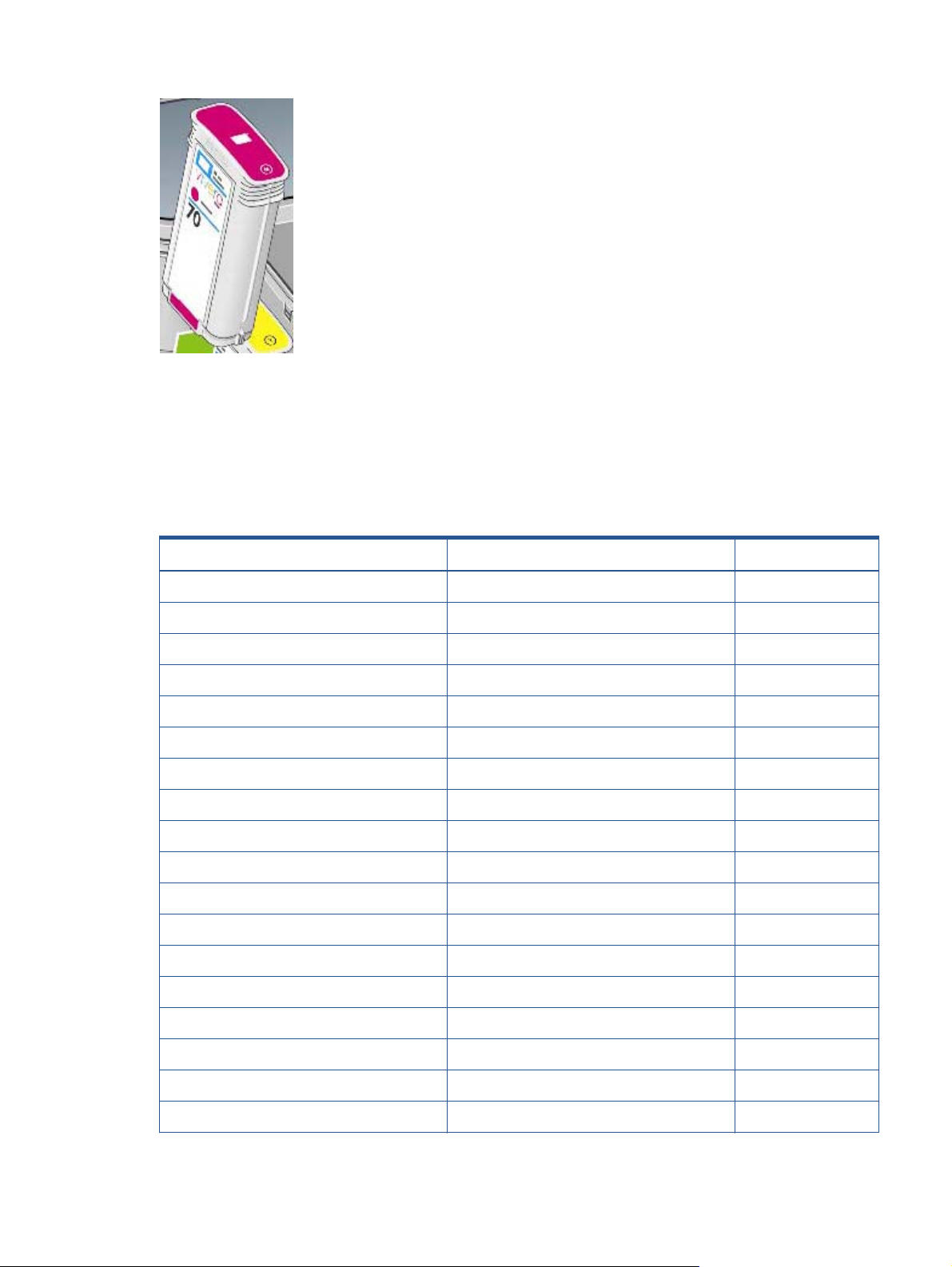
5. Pull the required Ink Cartridge straight up to remove it from the product. The Touch Control Panel
indicates the missing Ink Cartridge.
6. Before removing the cartridge from its wrapping, shake it vigorously.
7. Unwrap the new ink cartridge, find the label identifying the ink color. Check that the letter or
letters marking the empty slot, matches the letter or letters on the cartridge label.
8. Insert the ink cartridge into its slot.
9. Push the cartridge into the slot until it snaps into position. You will hear a beep and see
confirmation that the cartridge has been inserted.
10. When all cartridges have been inserted, close the cover.
Printhead information, replacement and alignment
Obtaining Printhead Information
1. Press on the Information icon.
2. Press on the Printhead Menu icon and the following screen is displayed, press on the printhead
that you want information on.
ENWW
Ink-supplies troubleshooting
23
Page 36

3. The Touch Control Panel displays information on the selected Printhead.
The information supplied is:
The current status of the printhead.
●
The color of the printhead.
●
The make of the printhead (HP no.72 is recommended).
●
The product number of the Printhead.
●
The serial number of the Printhead.
●
How much ink has been fired (consumed) by the printhead.
●
NOTE: It is possible for a printhead to consume more than one Ink Cartridge.
The current warranty status of the Printhead.
●
Changing a Printhead
To change a Printhead there are two methods, the first is shown below by using the printhead tab, the
second method is to access the main menu option (refer to the User's Guide for further details).
1. Press on the Information icon.
24 Chapter 1 Troubleshooting ENWW
Page 37

2. Press on the Printhead Menu icon and the following screen is displayed. Press on the Replace
Printhead tab.
3. A screen is displayed, showing an animation of how to install the printhead(s).
4. The product moves the Carriage to the correct position to replace Printheads.
NOTE: If the carriage is left in the removal position for more than three minutes without inserting
or removing any printheads, it will try to move back to its normal position at the right-hand end.
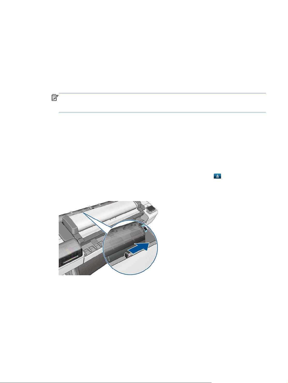
5. Open the Scanner (MFP only) or Window.
ENWW
6. Locate the carriage on the right side of the product.
7. Pull the blue handle up and toward you to release the Carriage Cover.
Ink-supplies troubleshooting
25
Page 38

8. Push the handle back.
9. This gives you access to the printheads.
10. The following screen is displayed
26 Chapter 1 Troubleshooting ENWW
Page 39

11. Remove a printhead by lifting up the blue handle.
12. Using the blue handle, use steady force to disengage the printhead.
13. Pull the blue handle upward until the printhead is released from the carriage.
CAUTION: Do not pull abruptly because this can damage the printhead.
14. The Touch Control Panel display identifies the missing printhead.
ENWW
Ink-supplies troubleshooting
27
Page 40

15. To insert a new printhead first remove the orange protective caps.
16. Insert the new printhead into its correct slot in the carriage.
CAUTION: Insert the printhead slowly and vertically, straight down. It may be damaged if you
insert it too fast, or at an angle, or if you rotate it as you insert it.
28 Chapter 1 Troubleshooting ENWW
Page 41

17. Push down as indicated by the arrow shown below.
CAUTION: When installing the new printhead there may be some resistance, so you need to
press it down firmly but smoothly. You should hear a beep and see confirmation on the Touch
Control Panel display that the printhead has been inserted.
18. Insert all other printheads that need to be installed, and close the carriage lid.
ENWW
19. Ensure the end of the blue handle catches the wire loop on the near side of the carriage.
Ink-supplies troubleshooting
29
Page 42

20. Lower the handle to rest on the carriage cover.
When all the printheads have been inserted correctly and are accepted by the product, the
product beeps.
NOTE: If the product does not beep when you insert the printhead and the Replace message
appears on the Touch Control Panel display, the printhead may need to be reinserted.
21. Lower the scanner.
22. The Touch Control Panel display confirms that all printheads are correctly inserted. The product
starts checking and preparing the printheads. The default routine process, when all printheads are
changed, takes 10 minutes. If the product finds problems in preparing the printheads, it takes
longer, up to 45 minutes. For a single printhead insertion, the times vary between 2 and 40
minutes. After all printheads are checked and prepared, the printhead realignment procedure runs
automatically if paper is loaded.
The Touch Control Panel display confirms that all printheads are correctly inserted.
The product will start checking and preparing the printheads. The default routine process, when all
printheads are changed, takes 25 minutes. If the product finds problems in preparing the
printheads, it will take longer, up to 55 minutes. For a single printhead insertion, the times vary
between 15 and 35 minutes. After all printheads are checked and prepared, for the printhead
realignment.
30 Chapter 1 Troubleshooting ENWW
Page 43

Aligning Printheads
Precise alignment between printheads is essential for accurate colors, smooth color transitions,
▲
and sharp edges in graphical elements. Your product has an automatic printhead alignment
process which runs a printhead has been accessed or replaced.
In cases where the paper has jammed, you have used a custom paper, or are experiencing
problems with color accuracy you may need to align the printheads. If the paper has jammed, it is
recommended that you reinsert the printheads and initiate the realignment procedure with the
Image Quality Maintenance menu.
NOTE: Do not use transparent and semi-transparent paper to align the printheads. Photo paper
is recommended for the best quality.
Reinsert Printheads Procedure
1. If the realignment process is running and the wrong paper is loaded, press the Cancel button on
the Touch Control Panel. Do not print if the realignment process has been canceled. You can
restart the alignment with the Image Quality Maintenance menu procedure.
2. Load the paper you wish to use. You can use a roll that is at least 610 mm (24 in) wide or a cut
sheet that is A2 landscape or larger.
3. Remove and re-insert all the printheads, see Remove a printhead and Insert a printhead. This will
start the printhead alignment procedure.
4. The process will take about six minutes. Wait until the Touch Control Panel display shows the
process complete before using the product.
Image Quality Maintenance Procedure
1. Load the paper you wish to use. You can use a roll that is at least 610 mm (24 in) wide or a cut
sheet that is A2 landscape or larger. Do not use transparent and semi-transparent paper to align
the printheads. Photo paper is recommended for the best results; plain, bond and thin coated
papers provide acceptable but marginal results.
2. Press the Menu button to access the main menu and select the Image Quality Maintenance menu
icon.
3. Select Align printheads. The product will check to see if it has enough paper to run the
realignment.
4. The realignment procedure will now be performed and the realignment pattern will be printed.
5. The process will take about five minutes. Wait until the Touch Control Panel display shows the
process complete before using the product.
Scanning errors during alignment
If the alignment process FAILs, a Scanning error message is displayed on the Touch Control Panel. This
means that the alignment has not completed successfully. The problem may be due to:
ENWW
Ink-supplies troubleshooting
31
Page 44

The paper used was not valid, repeat the alignment with valid paper.
●
Printhead health problems, clean printheads.
●
The alignment was done with the Scanner open, repeat the alignment with the cover closed.
●
If the problem persists after using valid paper, cleaning the printheads, and keeping the cover closed,
there may be a failure in the scanning system needing reparation or the printheads, although clean,
may not work and need to be replaced.
Ink cartridge and printhead status messages
Ink Cartridge Status Messages
OK The Ink Cartridge is operating correctly and no action is required.
Missing There is no Ink Cartridge present, or it is not properly connected to the product
Low The Low message is an early warning sign and it is advisable that new supplies should
be obtained of that particular color. The amount of ink remaining in the Ink Cartridge
depends on it’s capacity, but there is approximately 14% of ink available for the user.
Very Low When theVery Low message is displayed, overnight printing should not be attempted.
Changing the Ink Cartridge is strongly recommended to prevent the product from stopping
halfway through a print. There is approximately 8% of ink available for the user.
Empty The product will stop and will not be able to continue printing until a new Ink Cartridge
has been installed. If this occurs halfway through printing an image, you should check the
quality of this image, as stopping mid-plot can affect the print. It would be recommended
to reprint the image once a new Ink Cartridge has been installed.
Reseat You are recommended to remove the Ink Cartridge and then reinsert it.
Replace You are recommended to replace the Ink Cartridge with a new Ink Cartridge.
Altered There is something unexpected about the Ink Cartridge's status.
Expired The Ink Cartridge has passed the expiration date.
Printhead status messages
OK The Printhead is operating correctly and no action is required.
Missing There is no Printhead present, or it is not properly connected to the product.
Test printhead separately You are recommended to test the printheads individually to find the failing printhead.
Remove all the printheads and insert them alone one by one, Closing the latch and the
carriage cover after every insertion. The Touch Control Panel display will indicate the
failing one showing the reseat or replace message.
Reseat You are recommended to start the printhead removal process from the Touch Control
Panel, but instead of removing the printhead, simply press the OK button on the Touch
Control Panel.
Replace You are recommended to remove the printhead and then reinsert it; if that fails, clean the
electrical connections; if that fails, replace the printhead with a new printhead.
32 Chapter 1 Troubleshooting ENWW
Page 45

Replacement incomplete A printhead replacement process has not completed successfully, relaunch the replacement
process and let it finish completely (it is not needed to change the printheads).
Remove The printhead is not a suitable type for use in printing (for instance, a setup printhead).
Printhead Error Codes
The following table describes the Printhead Error Codes. Refer to the above descriptions of the status
messages for the appropriate action.
Error Code Status Name Status Message Description Comments
0 Working OK The printhead is working
properly
1 Fails Logical V Replace The printhead may have a vcc
short
2 Fails Continuity Reseat Could be caused by bad insertion.
4 Shutdown Not used
8 Fails Vpp Replace Suspected vpp ink short
16 Temp Extremely
High
32 Temp Extremely
Low
64 Temp too High Replace Printhead temperature above
128 Temp too Low Reseat Printhead temperature below
256 Bad Acumen
Info
Replace Printhead temperature above
normal margins
Reseat Printhead temperature below
normal margins
normal margins
normal margins
Replace Critical acumen info outside
margins
Better to reseat the PEN than to
reject it.
Could be caused by a short in the
ink supplies
Could be caused by bad Vpp
continuity
Could be caused by a short in the
ink supplies
Could be caused by bad Vpp
continuity
Printhead has a manufacturing
problem
ENWW
512 No Pen Missing There is no printhead
1024 Bad Accumen
Access
2048 Wrong Model Replace Wrong printhead inserted Mechanical lockouts should prevent
4096 Mismatch Replace Wrong color inserted Mechanical lockouts should prevent
8192 CSdata Not
Responding
16384 CSdata Transmit
Error
32768 Fails Energy
Calibration
Reseat or Test
Separately
Reseat CSdata commuication failed Could be caused by bad insertion
Reseat CSdata commuication
Reseat Energy calibration failed Could be caused by bad contact
Acumen cannot be accessed Bad acumen continuity or a short;
Cannot identify problem printhead
this. Error is redundant
this
Could be caused by bad contact
incorrect
Ink-supplies troubleshooting
33
Page 46

Error Code Status Name Status Message Description Comments
65536 Empty Dummy OK during Purge Requested during purge, otherwise
should be removed
131072 Full Dummy Remove Requested during purge
262144 End of Life Warning Printhead warranty expired
524288 Expired Warning Printhead has used expired or
non-HP ink
Solving ink-supply problems
Most of the problems that you could encounter when working with the ink supplies are solved with
guidance from the Touch Control Panel. A full list of Touch Control Panel messages are supplied in the
User’s Guide.
You Cannot Insert the Ink Cartridge Into the product
1. Ensure that you have the correct HP no.72 Ink Cartridge.
2. Ensure that the Ink Cartridge is the correct color for that slot.
3. Ensure that the Ink Cartridge is the correct orientation, with the color coded label at the top.
NOTE: Never clean inside the Ink Cartridge slots as this can cause damage to the product.
You Cannot Insert the Printhead Into the Product
1. Ensure that you have the correct HP no.72 Printhead.
2. Ensure that the printhead is the correct color for that slot.
3. Ensure that the printhead is in the correct orientation.
4. Ensure that the protective cap is removed from the Printhead.
The Touch Control Panel says to reset or replace a printhead
1. From the Touch Control Panel, turn the power off then on.
2. Check the Touch Control Panel display message, if it shows the ready message, the product is
ready to print. If the problem remains continue with the next step.
3. Remove the printhead.
34 Chapter 1 Troubleshooting ENWW
Page 47

4. Clean the electrical connections on the backside of the printhead with a lint-free cloth. You can
carefully use a mild rubbing alcohol if moisture is needed to remove residue. Do not use water.
You can use the Flex Contacts Cleaning Tool.
This is a delicate process and may damage the printhead. Do not touch the nozzles on the bottom
side of the printhead, especially not with any alcohol.
5. Reinsert the printhead.
6. Check the Touch Control Panel display message. If the problem remains, try a new printhead.
Maintaining and cleaning the printheads
Clean the printheads
As long as the product is kept turned on, an automatic cleaning is performed periodically. This ensures
there is fresh ink in the nozzles and prevents nozzle clogs, which ensures color accuracy.
For image quality issues, you can also refer to the Maintenance and Troubleshooting document.
To clean the printheads, press the Menu key to return to the main menu and select the Image Quality
Maintenance menu icon, then Clean printheads. If you have gone through the Image Quality
Diagnostic print process, you know which colors are failing. Select to the pair of printheads which
contain the failing colors. If you are not sure which colors to clean, you can also select to clean all
printheads.
Cleaning all printheads takes about nine minutes. Cleaning a single pair of printheads takes about six
minutes. Cleaning all printheads uses more ink than cleaning a single pair.
If you have cleaned the printheads using the Clean printheads procedure from the Touch Control Panel
and are still experiencing image quality problems, you can try cleaning the printhead nozzles manually
using the following procedure.
ENWW
NOTE: This is a delicate process and may damage the printhead. Do not touch the electrical
connections on the backside of the printhead.
Ink-supplies troubleshooting
35
Page 48

You must remove the printhead (see Changing a Printhead on page 24) and using a cotton swab and
a little de-ionized, distilled water, or Carriage Interconnect Wiper clean the bottom of the printhead
until the residue is removed.
Flex Contacts Cleaning Tool
NOTE: The Flex Contacts Cleaning Tool is part of the Maintenance Tool Kit. All the instructions
needed to use the Flex Contacts Cleaning Tool will be packaged with the kit.
Whenever you replace the Printhead, check the empty slots to see if they need cleaning. In extreme
circumstances, when a Printhead is inserted, it is possible that the product will not recognize it due to
the build-up of ink on the electrical connection between the Printhead and the Carriage Assembly.
Included with the product is a Flex Contacts Cleaning Tool. This tool is provided in a separate
package. It also contains replacement sponges and an instruction sheet. This tool should be used for
cleaning the electrical interconnects of both the Carriage Assembly and the Printhead.
If the Touch Control Panel displays the message “Reseat” or “Replace” next to the offending printhead,
try cleaning the flex circuits of the Carriage and the Printheads using the Carriage Interconnect Wiper.
NOTE: Do not touch, wipe or attempt to clean the printhead nozzles. This can damage the printhead
and reduce print quality.
36 Chapter 1 Troubleshooting ENWW
Page 49

Print Quality
Print Quality Troubleshooting Actions
NOTE: Phone support: For some Print Quality problems, a Call Agent can try and troubleshoot the
Printer by requesting the Customer to perform certain actions. Using this process, most problems can
resolved without the need of an on-site visit.
When faced with a Print Quality problem, perform the following actions in order to resolve the
problem:
1. Printer Configuration:
a. Check that the paper type loaded corresponds to the paper type selected in the front panel
and in the software. You can verify the paper type selected through the Front Panel. Press
. Press the paper icon.
b. Make sure that the correct Print Quality settings are used for different types of print content.
c. Dry time should be set to “Optimal”
2.
Perform Printhead recovery. Press
Maintenance / Clean Printheads
, then and then select Image Quality
3. Media:
a. Select the correct media type through the front panel when loading it
b. Make sure that HP or HP-approved media is being used.
4.
Perform the Printhead Alignment. Press
Maintenance/ Align Printheads),using the same paper type with which you were
experiencing unacceptable image quality, if feasible (some paper types are not suitable for
Printhead Alignment).
5. Check if the latest version of the firmware is installed. If not, install the latest firmware revision.
, then and then select Image Quality
ENWW
Print Quality
37
Page 50

The Service Image Quality Diagnostic Print
What is the Service Image Quality Diagnostic Print?
The Printer contains an internal Image Quality Test which helps you to diagnose the possible source of
any image quality defects. The Service IQ Diagnostic Print is available in the following options:
1. Image Quality Service Best Plot. This plot helps you to diagnose in more detail the possible source
of any image quality defects. It is accessible
a. Diagnostic Part 1: Printhead Reliability Test. The purpose of this test is to identify which
Printhead is faulty.
b. Diagnostic Part 2: Printhead Alignment Test. This test is designed to check any color-to-color
and bi-directional misalignment the printer may have.
c. Diagnostic Part 3: Printheads and Paper Advance test. This test is designed to check whether
the Printheads and the Media Advance Mechanism are working correctly.
2. Image Quality Service Normal Plot. This plot is the same as the Image Quality Service Best Plot but
uses the Normal Print Mode.
3. Advanced Diagnostic Plot. These tests provide more information of the IQ defects that we could
find in the Image Quality Service plot. For more information, refer to
on page 45.
Advanced Diagnostic Prints
Considerations for Printing the Diagnostic Print
1. The IQ Diagnostic Print prints in A3 and B sizes so you must have media loaded (roll or sheet) that
is this size or larger.
2. Use the same type of media that the customer was using when they found the image quality.
3. If the customer is using non-HP media and after the Image Quality Test you still have the same
image quality problems, change to genuine HP media and repeat the Image Quality Test.
4. If you do not see any problems with the Image Quality Test, the problem may not be with the
printer itself. The problem may be with the RIP or the driver.
If you do see problems with the Image Quality Test, continue with the Advanced Diagnostic procedures
which will help you diagnose the problem.
Printing the Diagnostic Print
1. In the Service Utilities submenu, scroll to “Diagnostic Print” and press OK.
38 Chapter 1 Troubleshooting ENWW
Page 51

2. You will be given three options. Use the Arrow keys to make the selection and press the OK key to
start printing the required Diagnostic Print or to enter the Advanced Diagnostics menu.
3. If you selected the Advanced Diagnostics Prints in the previous step, use the Arrow keys to make
the required selection Paper Advance, Visual Alignment Diagnostic, Nozzle Health, Force Drop
Detection or Print Banding Plot, and press the Enter key to start printing.
4. Make sure media is loaded, the Media Lever is lowered and that the Ink System is correctly
installed. Press the OK key to print the Diagnostic Print or press Back/ Cancel to exit without
printing the Diagnostic Print.
ENWW
5. The selected Diagnostic Print will now be printed.
The Service Image Quality Diagnostic Print
39
Page 52

Reading the Diagnostic Print Results
Diagnostic Part 1: Printhead Reliability
The Nozzle Print Test is designed to check if the Printhead nozzles print correctly.
The nozzles (bottom of the plot) are printed in a one-pass full swath mode. The diagnostics test prints
out every single nozzle of each Printhead without applying an error hiding or alignment algorithm.
For each Printhead, you can see both the adjacent and the consecutive nozzles.
If any nozzles are not printing correctly they will be shown on the right of each Printhead Nozzle test.
There is a series of numbered stepped diagonal lines. If one or more of the nozzles are clogged,
malfunctioning or mispositioned, you will see that the stepped lines are broken or misdirected in one or
more places.
Below, the stepped lines highlighted in yellow are broken. When the line is completely broken, this
means the nozzle is out.
Below, the stepped lines highlighted in yellow are misdirected. When the line is misdirected, this means
the nozzle is malfunctioning or out of position.
On the left of each Printhead Nozzle test, there is a series of horizontal straight lines. If one or more
nozzles are misdirected there will be unequal spaces between the corresponding lines.
40 Chapter 1 Troubleshooting ENWW
Page 53

Corrective Action
If the printer has nozzle defects, you can still get perfect print quality results. The printer can
automatically compensate for nozzle defects, so there is no need to replace the Printhead.
The method of improving Nozzle Defects is to:
1.
Recover the Printheads, using the Front Panel. Press
Quality Maintenance/ Clean Printheads.
2. Reprint the Printhead Nozzles Test Plot to verify that the defective nozzles have been corrected.
3. If the problem continues, replace the defective Printhead.
Diagnostic Part 2: Printhead Alignment
This test is designed to check any color-to-color and bi-directional misalignment the printer may have.
, then and then select Image
If the Printer is experiencing horizontal misalignment problems, the Alignment Test will show
something like this:
If the Printer is experiencing vertical misalignment problems, the Alignment Test will show something
like this:
ENWW
Reading the Diagnostic Print Results
41
Page 54

If the Printer is experiencing bi-directional misalignment problems, the Alignment Test will show
something like this:
Corrective Action
▲
Perform the Printhead Alignment using the Front Panel. Press
Image Quality Maintenance/ Align Printheads.
Diagnostic Part 3: Printheads & Paper Advance
This test is designed to check whether the Printheads and the Paper Advance Mechanism are working
correctly. This part of the Image Quality Test should NOT be used to check for color consistency or
accuracy.
Banding
If the Printer is experiencing a banding problem, you will see repetitive horizontal bands within the
printed image.
Darker horizontal bands or lines repeated along the vertical band (from top to bottom at the same
●
distance).
Whiter horizontal bands or lines along the vertical band (from top to bottom at the same distance).
●
The plot is printed in Best or Normal mode (according to the menu option selected) with Error Hiding
ON. The top band has 100% ink density patches while the bottom band has 50% ink density patches.
, then and then select
42 Chapter 1 Troubleshooting ENWW
Page 55

Troubleshooting Banding Problems
If banding does NOT occur in ALL the colors, then it is more than likely a Printhead problem. In this
case, try the following:
1. Check that the appropriate print quality settings are being used (refer to the User’s Guide for more
information).
2.
Recover the printheads using the option through the Front Panel. Press
, then and then
select Image Quality Maintenance/ Clean Printheads. Reprint the Diagnostic Print or the
print file and if the problem persists, replace the faulty Printhead.
If banding does occur in ALL the colors, then it is more than likely a Paper Advance problem:
If the bands are light, it means that the paper has advanced too much.
●
If the bands are dark, it means that the paper hasn’t advanced enough.
●
In high quality modes, graininess in ALL colors can indicate problems either with alignment or
●
Paper Advance.
Corrective Action
In order to solve problems that result in banding, try the following:
ENWW
Reading the Diagnostic Print Results
43
Page 56

1. Check that the appropriate print quality settings are being used (refer to the User’s Guide for more
information).
2. Check that the loaded media is the same type as selected in the printer. You can verify the media
type selected through the Front Panel. Press
3. If the customer is using low quality paper, try recommending better quality paper (preferably HP
paper). Printer performance can only be guaranteed by using recommended papers.
4. Perform the Paper Advance Calibration using the same type of paper that will be used for the final
print . Press
Calibration/ Calibrate Paper Advance.
If there is white point banding in only one color band and the problem cannot be fixed using the
Printhead recoveries, in some cases using the force a drop detection option can fix this issue. See
Force Drop Detection on page 52.
then and then select Image Quality Maintenance/ Paper Advance
, then press paper icon.
No Printing Defects Found in the Diagnostic Print
If all the test patterns from the Diagnostic Print are correct and you still experience Image Quality
problems, you can use the following procedures to resolve the problem.
Reading the Diagnostic Print Results on page 40
●
Printhead Alignment on page 49
●
Nozzle Health on page 51
●
Force Drop Detection on page 52
●
44 Chapter 1 Troubleshooting ENWW
Page 57

Advanced Diagnostic Prints
What are the Advanced Diagnostic Prints?
Advanced Diagnostic Plot. These tests provide more information of the IQ defects found in the Image
Quality Service plot.
The Advanced Diagnostic Plot is divided into the following parts:
Visual Media Advanced Diagnostic. Used to check advance reliability.
●
Visual Alignment Diagnostic. Used to check pen alignment reliability.
●
Visual Nozzle health Diagnostic. Used to check nozzle health reliability.
●
Force Drop Detection. Used to reset the nozzle health historic data base and force new drop
●
detection.
Printing the Advanced Diagnostic Prints
1. In the Service Utilities submenu, scroll to “Diagnostic Print” and press OK.
2. You will be given three options. Use the Arrow keys to select and press the Advanced
Diagnostics menu.
3. From the displayed options, use the Arrow keys to make the required selection Paper Advance,
Visual Alignment Diagnostic, Nozzle Health, Force Drop Detection or Print Banding Plot, and
press the Enter key to start printing.
ENWW
Advanced Diagnostic Prints
45
Page 58

4. Make sure media is loaded, the Media Lever is lowered and that the Ink System is correctly
installed. Press the OK key to print the Diagnostic Print or press Back/ Cancel to exit without
printing the Diagnostic Print.
5. The selected Advanced Diagnostic Print will now be printed.
46 Chapter 1 Troubleshooting ENWW
Page 59

Reading the Advanced diagnostic Print Results
Paper Advance
This plot helps you to visually check any alignment problems of the printer. You use it to precisely
measure the media advance error with a one dot row accuracy, and to verify the stability of the media
advance.
The whitest vertical line should be positioned in the 0 offset column with minor variations between +2
and -2 columns. If the offset is not positioned on the 0 column or between +2 and -2 columns and the
whitest vertical varies greatly, the printer requires Paper Advance Calibration. Press
and then select Image Quality Maintenance / Paper Advance Calibration / Calibrate
Paper Advance.
NOTE: It is very important to verify that the loaded media is the same media type as selected in the
front panel. You can verify the media type selected through the Front Panel. Press
icon. The wrong type of paper selected will produce an offset error in the Paper Advance.
The following plot shows correct media advance, there is a straight white line positioned close to the 0
column for the majority of the points.
then the Paper
then
ENWW
The following plot shows a bad media advance, there is a straight white line positioned close to the -6
column, instead of the 0 column for the majority of the points.
Reading the Advanced diagnostic Print Results
47
Page 60

Corrective Action
To fix Paper Advance problems, try the following:
1.
Check the Paper Advance Calibration Status. Press
then the Paper icon. At the bottom, the
Front Panel displays the Paper Advance Calibration status. There are three status messages:
DEFAULT. The paper loaded is recognized as HP paper, which is already optimized and
●
calibrated for the printer. Do not calibrate the Paper Advance for this paper.
RECOMMENDED. The paper loaded is NOT recognized as HP paper, and Paper Advance
●
values have NOT been customized for this paper type. In this case, calibrate the Paper
Advance from the user menu.
OK. This indicates that the paper loaded has been calibrated before. If the printer continues
●
to have banding and graininess problems, calibrate the Paper Advance from the user menu.
48 Chapter 1 Troubleshooting ENWW
Page 61

NOTE: Whenever the printer's firmware is upgraded, the paper advance calibration values will
be reset to factory default.
2.
To calibrate the Paper Advance from the user menu, Press
Quality Maintenance / Paper Advance Calibration / Calibrate Paper Advance.
NOTE: It is very important to verify that the loaded media is the same media type as selected in
the front panel. You can verify the media type selected through the Front Panel. Press
Paper icon. The wrong type of paper selected will produce an offset error in the Paper Advance.
NOTE: Some paper types are not suitable for Paper Advance Calibration. Do not use colored
papers or transparent materials such as translucent bond, clear film, matte film, tracing paper, or
vellum.
Paper Advance calibration from the user menu will only calibrate the Paper Advance for the paper
type loaded in the printer at that moment.
3. If Calibrate Paper Advance has mostly solved the problem, try Adjust Paper Advance to fine tune
the Paper Advance. Press
Paper Advance Calibration / Adjust Paper Advance.
Select the percentage of change from -100% to 100%. To correct light banding, decrease the
percentage. To correct dark banding, increase the percentage.
4. The Paper Advance calibration from the service menu will calibrate the Paper Advance for ALL
paper types. This action is recommended when:
then and then select Image Quality Maintenance /
then and then select Image
then the
The Paper Advance calibration from the user menu does not solve the problem.
●
The Paper Advance problems affect ALL paper types.
●
The procedure for Paper Advance Calibration is in the service menu
on page 216.
Printhead Alignment
This plot helps you to visually check any alignment problems of the printer. You use it to precisely
measure the alignment error with a one dot row accuracy. For the printer to be considered correctly
aligned, the results must be within ± 2 dot row.
The illustration shows the complete Printhead Alignment that identifies each of the specific alignment test
results covered. The plot is split into four areas printed at different speeds and resolutions:
25ips@1200dpi, 35ips@1200dpi, 36ips@600dpi and 50ips@600dpi.
Paper Advance Calibration
ENWW
What to see in the AutoPen Alignment Diagnostics
Reading the Advanced diagnostic Print Results
49
Page 62

1. At the left we have two checks for the pen to pen alignment in scan axis direction (Pen2Pen-Fwd &
Pen2Pen-Rev). It is forward and reverse. The area to check is the junction (marked with “-”) of the
black with the rest of colors. The arrows show the printing direction.
2. The bidirectional check is at the top, marked as number 2 (Bidir). Check that the lines are
continuous without a gap. The junction is marked with “-”. The arrows show the printing direction.
3. The pen to pen alignment in paper axis direction (PAD) is marked as number 3. The area to check
is the junction (marked with “|”) of the black with the rest of colors.
4. The ThetaZ of the printhead are checked in the area marked as 4. It checks in forward and
reverse direction. The area to check is the junction (marked with “-”). The lines have to be
continuous. The arrows show the printing direction.
5. The area marked as number 5 is a reference legend that shows junction misalignments of 2, 4
and 6 dots. The junction to check has to be equal to or below 2 in all the cases. If the error we
appreciate is above 2 dots, then realign the printheads again.
In the next example, the Pen2Pen (both Fwd and Rev) is above these 2 dots and the unit should be
realigned. Same happens with the ThetaZ (die2dieSAD). The rest of the pattern shows a right
alignment.
50 Chapter 1 Troubleshooting ENWW
Page 63

Nozzle Health
The print contains three separate parts.
1. The Variable Frequency Nozzle health plot with odd/even nozzles separation. This is used to
detect misdirected or weak nozzles, nozzles not working correctly at all frequencies.
2. Inspector measuring tool test plot.
NOTE: Test 2 should NOT be used by Service Engineers.
3. Nozzle Print Test which is also part of the Image Quality Service Plot. This test is designed to
check that the Printhead nozzles print correctly. The test prints out every single nozzle of each
Printhead. No error hiding or Printhead Alignment algorithm is applied. For each Printhead, you
can see both the adjacent and the consecutive nozzles.
ENWW
This is what you would see in the Nozzle Print Test part if there are nozzles not printing correctly:
Reading the Advanced diagnostic Print Results
51
Page 64

1. On the right of each Printhead Nozzle test, there is a series of numbered stepped diagonal lines.
If one or more of the nozzles are malfunctioning or out of position, you will see that the stepped
lines are broken or misdirected in one or more places.
2. On the left of each Printhead Nozzle test, there is a series of horizontal straight lines. If one or
more nozzles are misdirected there will be unequal spaces between the corresponding lines.
Corrective Action for Nozzle Defects
If the printer has nozzle defects, it does not mean that you will not get perfect print quality results. The
printer has automatic procedures to hide many nozzle defects.
1.
Perform Printhead recovery using the option through the Front Panel. Press
then select Image Quality Maintenance / Clean Printheads
2. Reprint the Nozzle Print test to check that the defective nozzles have been corrected.
3. If the problem continues, replace the defective Printhead.
In the next example, the Pen2Pen (both Fwd and Rev) is above these 2 dots and the unit should be
realigned. Same happens with the ThetaZ (die2dieSAD). The rest of the pattern shows a right
alignment.
, then and
Force Drop Detection
If the Nozzle Print Test plot has persistent white point banding in only one color that cannot be fixed
with a printhead recovery, you can use this option to resolve the problem by resetting the nozzle health
data base so that all nozzles are assumed to be correct.
Once the nozzle health data base has been reset drop detection is forced. The normal cause of this
white point banding in a single color is the incorrect detection of failed nozzles by the drop detector.
52 Chapter 1 Troubleshooting ENWW
Page 65

Troubleshooting Print Quality Problems
Print Quality General Advice
1. To achieve the best performance from the printer, only genuine HP accessories and supplies
should be used.
2. Make sure that the paper type selected in the Front Panel is the same as the paper type loaded
into the Printer.
3. Make sure to use the most appropriate print quality settings for your purposes. A lower print
quality is likely to be seen if the print quality slider has been moved to the Speed end of the
scale, or the custom quality level set to Fast.
4. Check that the environmental conditions (temperature, humidity) are within the temperature/
humidity range as specified for the Printer (refer to the User’s Guide for more information).
5. Check that the ink cartridges and printheads have not exceeded their expiration dates.
The procedure for Paper Advance Calibration is in the service menu
on page 216.
Horizontal Lines Across the Image (Banding)
Description of problem
When you look at the image you have printed, there are horizontal lines across the image. Shown
below is an example of what you might see if you have this problem:
Paper Advance Calibration
ENWW
Corrective Action
Troubleshooting Print Quality Problems
53
Page 66

1. Check that the paper type loaded corresponds to the paper type selected in the front panel and in
the software. You can verify the paper type selected through the Front Panel. Press
Paper icon.
2. Check that the appropriate print quality settings are being used (refer to the User’s Guide for more
information) and reprint the image. In some cases print quality problems can be resolved by
selecting a higher print quality level.
3. Print the Service Image Diagnostics Print, and clean any printheads that need cleaning. Reprint the
job in case the problem has been solved.
4. Check the paper advance calibration status. If the status is PENDING, perform the Paper Advance
Calibration. Press
Advance Calibration/ Calibrate Paper Advance.
5. After calibration reprint the job.
then and then select Image Quality Maintenance/ Paper
Lines are Missing, Too Thin, Too Thick
Description of problem
Shown below is an example of what you might see if you have this problem:
then the
Corrective Action
1. Check that the paper type loaded corresponds to the paper type selected in the front panel and in
the software. You can verify the paper type selected through the Front Panel. Press
Paper icon.
2. Check that the appropriate print quality settings are being used (refer to the User’s Guide for more
information). Select the custom print quality options in the Print dialog, try turning on the Maximum
detail option. Reprint the job in case the problem has been solved.
3. If the resolution of the image is greater than the printing resolution, a loss of line quality may be
seen. You can find the Max. Application Resolution option in the Windows driver dialog's
Advanced tab, under Document Options > Printer Features. Reprint the job in case the
problem has been solved.
4. Check the Printhead alignment status. If the status is PENDING, perform the Printhead Alignment.
Press
then and then select Image Quality Maintenance/ Align Printheads.
then the
54 Chapter 1 Troubleshooting ENWW
Page 67

5. Check the paper advance calibration status. If the status is PENDING, perform the paper advance
calibration. Press
Advance Calibration / Calibrate Paper Advance.
6. Use Part 3 of the Image Quality Diagnostic Print, check if there are a significant amount of nozzles
out in the color that is actually causing the problem (if see you a problem with the Black color
in the customer print, then only check the Black printhead in the Image Quality Diagnostic Print). If
there is a significant amount of nozzles out then replace the defective Printhead.
then and then select Image Quality Maintenance/ Paper
Problems with Stepped Lines
Description of problem
When you look at the image you have printed there are ‘stepped lines’ in the borders of arrows and
diagonal lines. The lines should be straight with no stepping.
Shown below is an example of what you might see if you have problems with Stepped Lines:
Corrective Action
1. The problems may be inherent in the image that you are trying to print. Try to improve the image
with the application that generated the file.
2. Check that the appropriate print quality settings are being used (refer to the User’s Guide for more
information).
3. Turn On the Maximum Detail option in the Driver.
4. Change the image rendering resolution to 300 dpi or 600 dpi depending on the printing needs.
You can find the Max. Application Resolution option in the Windows driver dialog's Advanced
tab, under Document Options > Printer Features.
Lines are Printed Double or in Wrong Colors
Description of problem
This problem can have various visible symptoms, as shown below:
ENWW
Troubleshooting Print Quality Problems
55
Page 68

Corrective Action
Reseat the Printheads by removing them and then reinserting them.
NOTE: As you reseat the printheads, the printer will automatically align the printheads. It is important
that the alignment is completed properly. See
Lines are discontinuous
If the lines are broken in the following way:
1. Check that the appropriate print quality settings are being used (refer to the User’s Guide for more
information).
2. Reseat the Printheads by removing them and then reinserting them.
NOTE: As you reseat the printheads, the printer will automatically align the printheads. It is
important that the alignment is completed properly. See
Aligning Printheads on page 31.
Aligning Printheads on page 31.
Lines are Blurred (Ink Bleeds from Lines)
Description of problem
This problem is often caused by the ink soaking into the paper, making the lines blurred and fuzzy. This
could be because of the humidity in the air.
56 Chapter 1 Troubleshooting ENWW
Page 69

Corrective Action
1. Check that the environmental conditions (temperature, humidity) are suitable for high-quality
printing.
2. Make sure that the paper type selected in the Front Panel is the same as the paper type loaded
into the Printer.
3. Try using a heavier paper type. When printing dense colors, it is recommended to use HP
Heavyweight Coated Paper HP Super, Heavyweight Coated Paper or thicker Digital Fine Art
papers.
4. If glossy paper is being used, try changing to a different type of glossy paper.
5. Select the custom print quality options in the Print dialog, and turn on the More passes option.
6. Allow the prints time to dry separately; do NOT cover or stack them.
7. Align the printheads. See the
Problems with Graininess
Description of problem
Shown below is an example of what you might see if you have problems with graininess:
Corrective Action
1. Check that the paper type loaded corresponds to the paper type selected in the front panel and in
the software. You can verify the paper type selected through the Front Panel. Press
Paper icon.
2. Check that printing is on the correct side of the paper.
Image Quality Maintenance Procedure on page 31.
then the
ENWW
Troubleshooting Print Quality Problems
57
Page 70

3. Check that the appropriate print quality settings are being used (refer to the User’s Guide for more
information). Select the custom print quality options in the Print dialog, and try turning on the
More passes detail option. Reprint the job in case the problem has been solved.
4. Check the Printhead alignment status. If the status is PENDING, perform the Printhead Alignment.
Press
5. Check the paper advance calibration status. If the status is PENDING, perform the paper advance
calibration. Press
Advance Calibration / Calibrate Paper Advance.
6. After Paper Advance Calibration, reprint the job.
Paper is not Flat
Description of problem
If the paper does not lie flat when it comes out of the Printer, but has shallow waves in it, you are likely
to see visible defects in the printed image, such as vertical stripes. This can happen when you use thin
paper that becomes saturated with ink.
Shown below is an example of what you might see if you have problems with the paper not being flat:
then and then select Image Quality Maintenance/ Align Printheads.
then and then select Image Quality Maintenance/ Paper
Corrective Action
58 Chapter 1 Troubleshooting ENWW
Page 71

1. Check that the paper type loaded corresponds to the paper type selected in the front panel and in
the software. You can verify the paper type selected through the Front Panel. Press
Paper icon.
2. Try using a heavier paper type. When printing dense colors, it is recommended to use HP
Heavyweight Coated Paper HP Super, Heavyweight Coated Paper or thicker Digital Fine Art
papers.
3. Make sure that only genuine HP paper is being used.
4. Check that the appropriate print quality settings are being used (refer to the User’s Guide for more
information).
5. Check that the environmental conditions (temperature, humidity) are within the temperature/
humidity range as specified for the Printer (refer to the User’s Guide for further information).
Print Scuffing or Scratching when Touched
Description of problem
The black ink pigment can smudge when touched by a finger, a pen, or some other object. This is
particularly noticeable on coated paper, matte proofing paper, and fine art material.
Glossy paper may be extremely sensitive to damage from the basket or to anything else that it contacts
soon after printing, depending on the amount of ink used and the environmental conditions at the time
of printing.
then the
Corrective Action
1. Handle prints carefully.
2. Avoid stacking prints on top of each other.
3. Disable the automatic cutter before printing, so that the print will not fall into the basket.
Ink marks on the paper
This problem may occur for several different reasons.
Horizontal smears on the front of coated paper
If a lot of ink is used on plain or coated paper, the paper absorbs the ink quickly and expands. As the
printheads move over the paper, the printheads may come into contact with the paper and smear the
printed image. This problem is normally seen only on cut sheets of paper (not on roll paper).
ENWW
Troubleshooting Print Quality Problems
59
Page 72

Corrective Action
1. Check that the paper type loaded corresponds to the paper type selected in the front panel and in
the software. You can verify the paper type selected through the Front Panel. Press
Paper icon.
2. Use a recommended paper type and the correct print settings.
3. If using sheet paper, try rotating the sheet 90 degrees. The orientation of the paper fibers may
affect performance.
4. Try using a heavier paper type. When printing dense colors, it is recommended to use HP
Heavyweight Coated Paper HP Super, Heavyweight Coated Paper or thicker Digital Fine Art
papers.
5. Try to increase the margins by relocating the image to the center of the page with the software
application being used.
Ink marks on the back of the paper
This can happen after a lot of border less printing, especially with nonstandard paper sizes. Ink
residues on the platen are likely to mark the back of the paper.
Corrective Action
then the
Clean the platen with a soft cloth. Clean each rib separately without touching the foam between the
ribs.
Problems with the Edges of objects
Stepped or not sharp
The edges of objects or lines appear to be poorly defined or lighter in density than expected.
60 Chapter 1 Troubleshooting ENWW
Page 73

Corrective Action
If the print quality slider has already been set to Quality in the Print dialog, select the custom print
quality options, and try setting the quality level to Normal (refer to the User’s Guide for more
information).
Darker than expected
The edges of objects seem darker than expected.
Corrective Action
If the print quality slider has already been set to Quality in the Print dialog, select the custom print
quality options, and try setting the quality level to Normal.
Bronzing
When printing on photo paper with gray and black ink only a gloss differential problem can be
encountered when light is directly reflected from the print, producing 'bronzed' reflections where ink
has been laid.
Corrective Action
Use the Full set of inks option.
Black and white prints do not look neutral
Consider printing in grayscale (color options submenu inside the printing preference menu). See the
Useŕs Guide for more information.
Horizontal lines at the end of a cut sheet print
There is a type of defect that only affects the end of a print, within approximately 30 mm of the trailing
edge of the paper. Some very thin horizontal lines may be seen across the print.
Corrective Action
ENWW
Troubleshooting Print Quality Problems
61
Page 74

1. Print the Service Image Diagnostics Print, and clean any printheads that need cleaning. Reprint the
job in case the problem has been solved.
2. Try printing with roll paper.
3. Try using larger margins around the image.
Vertical lines of different colors
The print has vertical bands of different colors along it.
Corrective Action
1. Try using a heavier paper type. When printing dense colors, it is recommended to use HP
Heavyweight Coated Paper HP Super, Heavyweight Coated Paper or thicker Digital Fine Art
papers.
2. Use higher print quality settings (refer to the User’s Guide for more information).
White spots on the print
White spots are seen on the print. This is probably due to paper fibers, dust, or loose coating material.
Corrective Action
1. Clean the paper manually with a brush before printing, to remove any loose fibers or particles.
2. Always keep the cover of the printer closed.
3. Protect paper rolls and sheets by storing them in bags or boxes.
Problems with Color Accuracy
Corrective Action
62 Chapter 1 Troubleshooting ENWW
Page 75

1. Ensure that the paper type being used has been color calibrated, which will give color consistency
from print to print, and from Printer to Printer.
2. Check that printing is on the correct side of the paper.
3. Check that the appropriate print quality settings are being used (refer to the User’s Guide for more
information). Reprint the job in case the problem has been solved.
4. If the problem consists of color differences between your print and your monitor, please follow the
instructions in the "How to calibrate your monitor" section of the HP Color Center. At this point,
you may wish to reprint your job in case the problem has been solved.
5. Select suitable options in the application (refer to the User’s Guide for more information).
6. Print the Service Image Diagnostics Print, and clean any printheads that need cleaning. Reprint the
job in case the problem has been solved.
Color accuracy using EPS or PDF images in page layout applications
Page layout applications such as Adobe InDesign and QuarkXPress do not support color management
of EPS, PDF, or grayscale files.
If these types of files have to be used, try to ensure that the EPS, PDF, or grayscale images are already
in the same color space that is intended to be used later on in Adobe InDesign or QuarkXPress. For
instance, if the final objective is to print the job in a press that follows the SWOP standard, at the time
of creating the EPS, PDF or grayscale the image should be converted into SWOP.
Output Only Contains a Partial Print
If the output that was expected only contains a partial image, then try the following to resolve the
problem:
1. Was the Cancel key pressed before all the data was received by the Printer? If so, send the file
again and make sure that the Cancel key is not pressed.
2. The I/O Timeout setting may be too short. Increase the I/O timeout setting (Setup Menu/I/O
Setup/ IO Timeout) and then send the file again.
3. There might be a communications problem between the Printer and Computer. Check the USB or
network cable between the computer and the Printer to make sure it is not damaged and is
connected correctly.
4. Make sure that the software settings are correct for the current page size (e.g. long-axis prints).
5. If network software is being used, make sure it has not timed out.
Problems with Image Clipping
This normally indicates a discrepancy between the actual printable area on the loaded paper and the
printable area as understood by the software. This kind of problem can often be identified before
printing by previewing the print.
ENWW
Troubleshooting Print Quality Problems
63
Page 76

1. Check the actual printable area for the paper size that is loaded. printable area = paper size –
margins.
2. Check what the software understands to be the printable area (which it may call “printing area” or
“imageable area”). For example, some software applications assume standard printable areas
that are larger than those used in this Printer.
3. If a custom page size with very narrow margins has been defined, the printer may impose its own
minimal margins, clipping the image slightly. Consider using a larger paper size, or border less
printing.
4. If the image contains its own margins, it may be possible to print it successfully by using the Clip
Contents by Margins option.
5. If a very long image needs to be printed on a roll, check that the software is capable of printing
an image of that size.
6. The page may have been rotated from portrait to landscape on a paper size that is not wide
enough.
7. If necessary, change the printable area in the software.
8. If necessary, reduce the size of the image or document in your software application, so it fits
between the margins.
Another Possible Explanation
Some applications, such as Adobe Photoshop, Adobe Illustrator, and CorelDRAW, use an internal 16–
bit coordinate system which means that they cannot handle an image of more than 32,768 pixels. If
you try to print an image larger than this from these applications, the bottom of the image will be
clipped. In this case, the only way to print the whole image is to reduce the resolution so that the whole
image requires fewer than 32,768 pixels. The HP-GL/2 printer driver contains an option called
Compatibility with 16–bit applications, which can be used to reduce the resolution of such
images automatically. This option can be found in the Advanced tab, under Document Options >
Printer Features.
Some objects are missing from the printed image
Large quantities of data may be necessary to print a high-quality large format print job, and in some
specific workflow there may be issues that can lead to some objects missing from the output.
Corrective Action
1. In the Advanced tab, select Document options, Printer features, and set Send job as
bitmap to Enabled (HP-GL/2 driver only).
2. In the Advanced tab, select Document options, Printer features, and set 16-bit App.
Compatibility to Enabled.
3. In the Advanced tab, select Document options, Printer features, and set Max. Application
resolution to 300.
64 Chapter 1 Troubleshooting ENWW
Page 77

The above settings are mentioned for troubleshooting purposes and may adversely affect the final
output quality or the time necessary to generate the print job. Therefore, they should be restored to their
default values if they do not help to solve the problem.
When working under Mac OS, the above settings are not available. Instead, try reducing the resolution
of bitmap images in the application software being used.
A PDF file is clipped or objects are missing
In older versions of Adobe Acrobat or Adobe Reader, large PDF files could be clipped or lose some
objects when printing with the HP-GL/2 driver at high resolution. Upgrade the Adobe Acrobat or
Adobe Reader software to the latest version. From version 7 onwards, these problems should be solved.
ENWW
Troubleshooting Print Quality Problems
65
Page 78

Connectivity troubleshooting
Connectivity problems are resolved differently for USB, embedded LAN and Jetdirect connectivity.
Follow the advice given in the appropriate section below.
Embedded LAN connectivity troubleshooting
Perform the following procedure, checking the connectivity carefully after each step to see whether the
problem has been fixed.
1. Change the LAN cable.
a. Disconnect the LAN cable at both the remote end and the product end of the cable.
b. Reconnect using the LAN cable. Use a different LAN cable if possible.
2. Try connecting to a different Ethernet socket in your network, router or switch.
3. If possible, try to reset the Ethernet switch or router. This may involve turning it off and on again.
4. Adjust the configuration settings.
a.
Print out the original product I/O settings: from the Touch Control Panel, press
then select the Internal Prints menu, then Service information prints > Print
connectivity config.
, then
b. Reset the I/O to factory defaults: from the Touch Control Panel, select the Connectivity menu,
then Advanced > Restore factory settings.
c. Restart the product and wait 5 minutes.
d.
Print out the new product I/O settings: from the Touch Control Panel, press
then select the Internal Prints menu, then Service information prints > Print
connectivity config.
e. Connect to the product’s Embedded Web Server using the URL shown in the main page of
the Touch Control Panel.
f. Compare the configuration information printed out before and after restoring to factory
default settings. Set any custom I/O settings that may have been lost back to their desired
values using the Configuration information printed.
g. Run the Network Connectivity Test in the Diagnostic & Troubleshooting wizard: From the
Touch Control Panel press
troubleshooting > Web-connected printer wizard> Network connectivity Test
, then go to Connectivity > Diagnostics &
, then
66 Chapter 1 Troubleshooting ENWW
Page 79

Internet communication failures
If the printer has difficulty in connecting to the Internet, it will display an error message, which enables
you to launch a diagnostic that will automatically detect possible issues in your networking and Internet
access. You can also run the connectivity troubleshooting wizard from the Touch Control Panel or the
EWS.
●
From the Touch Control Panel: Press
troubleshooting > Web-connected printer wizard
From the EWS: Select Support > Connectivity troubleshooting > Web-connected
●
printer wizard.
●
From the Touch Control Panel go press
information prints > Print connectivity config. the results are then printed out.
The web connected printer wizard can help you:
To correctly configure the internet connection
●
Configure the Automatic Firmware Update
●
Troubleshoot Internet connection issues
●
You can choose to perform all the tests or individual tests. The following options are available:
All tests
●
Network connectivity test: check the printer's connection to the local area network
●
Internet connectivity test: check the printer's connection to the Internet
●
then go to Connectivity > Diagnostics &
, then go to Internal prints > Service
Firmware update test: check the printer's connection to HP's firmware update servers.
●
If any test fails, the printer describes the problem and recommends how to solve it.
USB device connectivity troubleshooting
If the product experiences problems with the USB connection (the computer does not detect the product
when the USB cable is plugged in) or with USB performance (throughput is slow) then try the following
checks.
Check that the Connectivity is not disabled through the I/O Interfaces Utility,
●
Utility on page 165
Check that the USB port in the computer is a “USB 2.0 High Speed” port. Some old computers
●
and USB hubs have slower “USB 1.1 Full Speed” ports, and those should not be used with
Designjet products. Do not ignore a warning message on your computer such as:
Check the USB cable.
●
Enable I/O Interfaces
ENWW
Connectivity troubleshooting
67
Page 80

Check that the USB cable is USB 2.0 Certified: check the USB logo on the packaging of
◦
the cable, or on the cable itself, or check the specifications of the cable.
Try a shorter USB cable. Cables close to the 5 m limit often cause problems.
◦
Make sure the USB cable doesn’t pass near possible sources of electrical interference (CRT
◦
monitors, engines, etc.).
Connect the product to a different USB port on the computer. If possible, try using a different
●
computer.
Remove any other USB devices from the computer, or connect them to different USB ports.
●
EIO Jetdirect card connectivity troubleshooting
Perform the following procedure, checking the connectivity carefully after each step to see whether the
problem has been fixed.
1. Check that connectivity is not disabled, .
2. Change the LAN cable.
a. Disconnect the LAN cable at both the remote end and the product end of the cable.
b. Reconnect using the LAN cable. Use a different LAN cable if possible.
3. Try connecting to a different Ethernet socket in your network, router or switch.
4. If possible, try to reset the Ethernet switch or router. This may involve turning it off and on again.
5. Adjust the configuration settings.
a. Print out the original Jetdirect I/O settings: from the Touch Control Panel, select the Internal
Prints menu, then Service information prints > Print connectivity config.
b. Print out the original Jetdirect protocol settings: from the Touch Control Panel, select the
Connectivity menu, then Jetdirect EIO > Modify configuration > Information > Print
protocols > Yes. Return to the main menu.
c. Reset the Jetdirect I/O to factory defaults: from the Touch Control Panel, select the
Connectivity menu, then Jetdirect EIO > Restore factory settings.
d. Restart the product and wait 5 minutes.
e. Print out the new Jetdirect I/O settings: from the Touch Control Panel, select the Internal
Prints menu, then Service information prints > Print connectivity config.
f. Print out the new Jetdirect protocol settings: from the Touch Control Panel, select the
Connectivity menu, then Jetdirect EIO > Modify configuration > Information > Print
protocols > Yes. Return to the main menu.
68 Chapter 1 Troubleshooting ENWW
Page 81

g. Connect to the product’s Embedded Web Server using the URL shown in the main page of
the Touch Control Panel.
h. Compare the configuration information printed out before and after restoring to factory
default settings. Set any custom I/O settings that may have been lost back to their desired
values using the Configuration information printed.
USB host features
A USB host port is available in the formatter to support new features that may become available in the
future. As a security precaution, the USB port can be disabled through the EWS,
Utility on page 165
Accessories
There are two different accessories that can be connected into the USB Host port:.
PostScript Upgrade Dongle, part number CN500B. This accessory is compatible with all HP
●
Designjet T790, T1300 and T2300 series.
External Hard Disk Drive, part number CN501A. This accessory is compatible with all the HP
●
Designjet T790, T1300 and T2300 series. When this accessory is connected the product will
keep all user data stored in the external hard disk only, which can be removed from the product
and stored separately for confidentiality or security reasons.
Enable I/O Interfaces
Copying the diagnostic package to a USB flash drive
The diagnostic package contains useful information from the product to help you to find the cause of a
problem. The USB host port provides a quick and easy way to retrieve this information into a standard
USB flash drive. See
on page 122.
Appendix C: Obtaining the product log and the diagnostics package
Firmware upgrade with USB flash drive
The USB host port can be used to upgrade the product's firmware of the product using a standard USB
flash drive. In this case only a valid .FMW firmware package may be stored in the drive, and it must
be in the root folder, not in a sub folder. Connect the USB flash drive and follow the instructions on the
Touch Control Panel. The USB host port can be used at any time, regardless of what procedure the
printer is performing.
Special firmware upgrades
Emergency firmware upgrade using a USB flash drive
When it is not possible to perform a firmware upgrade using the normal procedures (for instance, in
case of a System Error and the Embedded Web Server is unavailable), it is possible to perform an
emergency firmware upgrade using a USB flash drive. See
with USB flash drive on page 121.
Appendix B: Emergency firmware upgrade
ENWW
Connectivity troubleshooting
69
Page 82

Forced firmware upgrade
When the product is started for the first time, a wizard will start. The last step of the wizard asks the
user to configure the automatic firmware update settings, and then and there the user is forced to check
if there is a new version of the firmware available. In certain circumstances the printer may require a
firmware upgrade before it can initialize completely. When this occurs there will be a USB flash drive
in the shipping box with
In certain circumstances the printer may require a firmware upgrade before it can initialize completely.
When this occurs there will be a USB flash drive in the shipping box with the product. Follow the
instructions that come with the flash drive.
NOTE: The USB flash drive is provided only to upgrade the product's firmware. No other uses of the
USB flash drive are supported.
If for any reason the USB flash drive upgrade option fails, download the firmware from the HP.com
website instead. Load the firmware onto any empty flash drive and insert the flash drive into one of the
USB ports of the product. The product will recognize the firmware on the flash drive and display the
install procedure on the Touch Control Panel.
70 Chapter 1 Troubleshooting ENWW
Page 83

2 System Error Codes
Introduction
●
Product logs
●
What to do if the Touch Control Panel is blank
●
Troubleshooting system Error 08:11 using LEDs of the Formatter
●
Continuable and Non-Continuable Error Codes
●
System Error Code Brief Descriptions
●
System Error Codes—Full Descriptions
●
Appendix A: How to troubleshoot SE 79:04
●
Appendix B: Emergency firmware upgrade with USB flash drive
●
Appendix C: Obtaining the product log and the diagnostics package
●
Appendix D: How to check the display list memory for an HP-GL/2 job
●
Introduction
Understand System Error Codes
System error codes are generally used to report internal system errors. The following pages contain a
list of system error codes and their respective descriptions and recommended corrective actions. Try
only one recommended action at a time, in the order that they appear, and check whether the error
code has disappeared.
Reporting a system error to HP support
If you have an error code that you cannot resolve, then report the error to the HP Response Center or
the nearest HP Support Office. When reporting the error, have the following information ready:
NOTE: If you fail to provide any of the following information, HP Support cannot help you properly.
Make sure you take time to gather all of this information.
ENWW
Introduction
71
Page 84

Model and Serial Number of the product, this can be found in the Diagnostics menu, scroll to Unit
●
Information.
Which firmware revision the unit is using. this can be found in the Diagnostics menu, scroll to Unit
●
Information.
The complete error number, this information can be found in the Product/Printer Information Area.
●
●
The Service Configuration Print. To print this press
Prints>Service Information Prints'.
, then go to 'Internal
●
The Current configuration sheet. To print this press
Prints>Service Information Prints'.
Which software application the customer is using.
●
The internal error code, file, and line fields found on the Internal Error Screens available Press on
●
the bottom right area of the touchscreen (same place where the cancel icon is usually displayed).
NOTE: The file and line fields are important to identify the source of the problem because the
same internal Error Code can be reported in different files and line. In the File field, supply only
the last part of the value (from last slash “/” to the end of the line). For example: for a
file: /ae/…./elektra/hal/motors/ControlledMotor/Elektra/ControlledMotorElektra.cpp you’ll only
need to provide the “ControlledMotorElektra.cpp” part to HP support.
TIP: When investigating a system error, you are recommended to use the diagnostic package to
further understand the problem. To obtain the diagnostic package (which takes a few minutes), see
Appendix C: Obtaining the product log and the diagnostics package on page 122.
Product logs
It is possible to view all the activities the printer performs collected in a log file. To further understand a
system error code, it is useful to have a log showing what the printer was doing at the time when the
system error occurred.
, then go to'Internal
To get product logs, see
on page 122.
Appendix C: Obtaining the product log and the diagnostics package
What to do if the Touch Control Panel is blank
The LEDs of the formatter (visible through the cover) and the power supply can help you troubleshoot a
problem if the Touch Control Panel is blank.
The following image shows the Power Supply LED, looking through the cover.
72 Chapter 2 System Error Codes ENWW
Page 85

The following image shows the Formatter LEDs, which should be marked I, II and III.
Follow these steps to troubleshoot the issue.
1. Switch the power off from the back of the product and disconnect the power cord. Reconnect the
power cord and power on the product.
2. Check that the Touch Screen Panel interface cable is not damaged and is correctly connected
between the Engine PCA and the Touch Control Panel.
3. Check that the connections between the Formatter and the Engine PCA are not damaged and are
correctly connected.
4. Use the following table to interpret the LEDs and find the source of the problem. Remember that
you should read these LEDs when you push the Power button.
Some combinations may require the replacement of two or more components. In this case, always
replace one component at a time. Test the product to see if the problem has disappeared (check
the LEDs again). If the same LED sequence continues, replace the next component indicated in the
table.
ENWW
Power
supply
LED
1 Off Off Off Off Off Power supply, see
2 On Off Off Off Off Engine PCA, see
3 On On Off Off n/a Reseat the Formatter, if this does not solve the issue,
Formatter
I LED
Formatter
II LED
Formatter
III LED
Touch
Control
Panel
status
Part to change
Power Supply Unit on page 466
EE Box on page 370.
replace the Formatter, see
Formatter on page 381.
What to do if the Touch Control Panel is blank
73
Page 86

Power
supply
LED
4On *Flashing*Off Off n/a 1. Reseat the Formatter.
Formatter
I LED
Formatter
II LED
Formatter
III LED
Touch
Control
Panel
status
Part to change
2. Hard Disk Drive, see
on page 389.
3. Formatter cannot unlock the hard disk due to a
password issue. This will happen if you try to
install an encrypted hard disk with a unique ATA
password in a different printer than the one you
installed it first. Remember to replace both
formatter and hard disk in case of a Revision B
printer.
5 On On *Flashing* Off n/a 1. Reseat the Formatter.
2. Hard Disk Drive, see
on page 389.
6OnOnOnOffn/a1. Formatter, see
2. Engine PCA, see EE Box on page 370.
7 On On On *Flashing* n/a Engine PCA, see
8 On *Flashing* On On Off Check the cables, if they are ok replace the
interconnect PCA, see
on page 411.
9 On Off On on Off 1. Check the USB cable of the Touch Control Panel,
if the cable is ok, replace the Touch Control
Panel, see
EE Box on page 370.
Touch Control Panel on page 547.
Hard Disk Drive
Hard Disk Drive
Formatter on page 381.
Interconnect PCA
2. Replace the Interconnect PCA, see
PCA on page 411.
10 On Off Off *Flashing* Off 1. Check the Power cable of the Touch Control
Panel, if the cable is ok, replace the Touch
Control Panel, see
on page 547
2. Replace the Interconnect PCA, see
PCA on page 411.
11 On Off *Flashing* *Flashing* Off 1. Issue with the firmware, upgrade the product to
the latest firmware, or reinstall the firmware.
2. Replace the Touch Control Panel, see
Control Panel on page 547
12 On On On On Touch
Control
Panel
light on
13 On On On On Off Replace the
All LEDs on for a few seconds is the normal part of the
initialization of the product. If however the LEDs stay
on, this would indicate a greater problem,
communicated via a system error code on the Touch
Control Panel.
Touch Control Panel on page 547.
Touch Control Panel
Interconnect
Interconnect
Touch
74 Chapter 2 System Error Codes ENWW
Page 87

If the printer freezes while initializing, the following explanation can help you understand at which
point of the initialization process it stopped and what could be the cause of the problem:
1%: This is equivalent to a system error 08:11, perform the troubleshooting procedure for 08:11.
●
If there is a communication failure between the Touch Control Panel and the Engine PCA, the
following message will display “Time out initialization”. If the communication is lost for more than
24 seconds, the system error 08:04 might display. In this case, perform the troubleshooting
procedure for 08:04.
2-20%: Initializing Touch Control Panel. If the printer freezes between these two percentages,
●
replace the Touch Control Panel see
20%: Linux Operating system starts up. From this point on, other parts of the printer besides the
●
Touch Control Panel on page 547
Touch Control Panel could be causing the problem.
32%: Communication between the Touch Control Panel and the printer is checked again. If the
●
connection fails it might show system error 08:04 but it might be hidden and just freeze. NVM is
also initialized at this point. If the printer freezes at this point, check the HDD, Encoder PCA and
Touch Control Panel, and follow the troubleshooting for system error 08:04.
34%: Initializing printer I/O. If the printer freezes at this point, try starting up without any external
●
connections (USB/network). Usage counters are initialized. Replace HDD, see
Hard Disk Drive
on page 389 and Formatter see Formatter on page 381.
94%: Initializing printer processes: mechanical movements, sensors, scan axis, web server. Start
●
the printer without printheads, supplies and external connections. Parts to be replaced are multiple
at this point, please check what the printer is doing just before it freezes to get more information
about what could be failing.
ENWW
What to do if the Touch Control Panel is blank
75
Page 88

Troubleshooting system Error 08:11 using LEDs of the Formatter
Formatter
LED 1
On Off Off 1. Reseat the Formatter.
Flashing Off Off 1. Reseat the Formatter.
On Flashing Off
On On Off 1. Reseat the Formatter, see note below.
On On Flashing 1. Reseat the Formatter, see note below.
Formatter
LED 2
Formatter
LED 3
Action for technician
2. Replace the Formatter, see
3. Check the connections of USB cable from Engine to Interconnect PCAs.
4. Replace the Engine PCA, see
2. Replace the Hard Disk, see
3. Check the connections of USB cable from Engine PCA to Interconnect PCA.
4. Replace the Interconnect PCA, see
2. Check the connections of USB cable from Engine to Interconnect PCAs.
3. Replace the Formatter, see
on page 370
4. Replace the Touch Control Panel, see
Formatter on page 381
EE Box on page 370
Hard Disk Drive on page 389
Interconnect PCA on page 411
Formatter on page 381 and Engine PCA, see EE Box
Touch Control Panel on page 547
2. Replace the Engine PCA, see
3. Check the connections of USB cable from Engine to Interconnect PCAs.
4. Replace the Interconnect
Interconnect PCA on page 411
, see
On On On 1. Upgrade the firmware.
2. Replace the Hard Disk Drive, see
3. Check the connections of USB cable from Engine to Interconnect PCAs.
4. Replace the Interconnect PCA, see
EE Box on page 370
Hard Disk Drive on page 389
Interconnect PCA on page 411
NOTE: Reseat the printer’s formatter by loosening the formatter screws, disconnect and reconnect the
formatter, and tighten the screws again.
NOTE: For Revision B printers the Formatter and Hard Disk are replaced as a single part,
76 Chapter 2 System Error Codes ENWW
Page 89

Continuable and Non-Continuable Error Codes
Some of the Error Codes are continuable, which means you can press OK on the Touch Screen Panel
and continue working with the product. Non-Continuable Error Codes do not allow you to continue
working with the product, in this case power the product OFF and ON again and see if the System
Error disappears. If the Error Code reappears, then the product requires an on-site visit in order to
resolve the problem.
System Error Code Brief Descriptions
Reading a System Error Code
System Error Codes explain which component/system is failing and what action should be taken to
resolve the problem.
System Error Codes are displayed directly on the Touch Control Panel (but can also be seen on the
Information Page) and have been defined in the format XX.YZ. or XX.n:YZ.m.
XX: Subsystem or process (2 digits).
●
n: Subsystem or process index (if more than one used in the product) – optional.
●
– e.g. Identify the Ink Supply (color and number).
Y: Who should perform the action (1 digit) – (0 for User or 1 for Service Engineer).
●
Z: Action to perform (1 digit).
●
System Error Code Table
The following table explains the XX part of the System Error Code or Warning:
Code Component/System
01.0 Engine PCA/Electronics module
02.1 Carriage PCA
03 Power supply
06 Formatter
08 Formatter/Touch Control Panel
09 Scanner (MFP only)
11 Trailing cable
21 Service station
22 Ink supply station
24 Tube assembly (IDS)
ENWW
26.n Ink Cartridge (color = n)
27 Printhead error
Continuable and Non-Continuable Error Codes
77
Page 90

Code Component/System
38 Output Tray
39 Roll switches
41 Paper-axis motor
42 Scan-axis motor
44 Aerosol fan
45 Rewinder
47 Star wheel motor
48 PPS mechanism
51 Top Cover Sensor
52 Drop detector
55 Line sensor
56 Drive roller analog encoder sensor
59 Electrical system
60 Initialization
61 Print queue
63 Input/output through LAN card
64 Input/output through USB port
65 Input/output (not known what port)
68 Loss of engine counters tracking
71 Memory management
72 Calibration
73 Servo
74 Firmware upgrade
74.1 Media Profile Update
75 Preventive Maintenance Kits
76 Disk Full
78 Media settings
79 Firmware
81 Media advance
84 Roll Feed
86 Paper path
78 Chapter 2 System Error Codes ENWW
Page 91

Code Component/System
87 Scan axis
93 Ink Pumping
Corrective Actions Table
The following table explains the YZ part of the System Error Code or Warning:
Code Recovery Action Response
00 Replace Possible for customer to perform
01 Reseat/Reconnect/Clean/Adjust (manually)
02 Calibrate/Adjust (using Automatic Process)
03 Power off and restart the product
04 Upgrade System Firmware
05 Upgrade Driver or Computer Software
06 Add Accessory
07 Escalate
action
08 Send Plot Again
09 Wrong Part Installed
10 Replace HP qualified personnel assistance
11 Reseat/Reconnect/Clean/Adjust (manually)
12 Calibrate/Adjust (using Automatic Process)
13 Power off
14 Upgrade System Firmware
15 Upgrade Driver or Computer Software
16 Add Accessory
17 Escalate
18 Send Plot Again
19 Wrong Part Installed
required
ENWW
System Error Code Brief Descriptions
79
Page 92

System Error Codes—Full Descriptions
This sections describes each of the system error codes and warnings that could be encountered while
using the product and provides the repaperl action required to solve the problem detected.
NOTE: Replace one component at a time and check whether the error has gone before replacing
another component. Using this procedure you will be able to determine exactly which component
failed.
System Error: 01.0:YZ
Problem Description: Communication with Engine PCA failed
Corrective action: Try the following:
1. Switch the power off from the back of the product and disconnect the power cord.
Reconnect the power cord and power on the product.
2. Remove the Formatter and reinsert it again. Ensure that it connects properly in the Engine
PCA connector.
Replace the Engine PCA. See
●
Replace the Formatter. See Formatter on page 381.
●
NOTE: For Revision B printers the Formatter and Hard Disk are replaced as a single
part,
System Error: 01.1:YZ
Problem Description: Error in the Engine PCA
Corrective action: Try the following:
1. Switch the power off from the back of the product and disconnect the power cord.
Reconnect the power cord and power on the product.
2. Replace the Engine PCA. See
3. Replace the Formatter. See
NOTE: For Revision B printers the Formatter and Hard Disk are replaced as a single
part,
System Error: 01.2:YZ
EE Box on page 370.
EE Box on page 370.
Formatter on page 381.
80 Chapter 2 System Error Codes ENWW
Page 93

Problem Description: Failure communicating with an Ink Supply
Corrective action: Try the following:
1. Switch the power off from the back of the product and disconnect the power cord.
Reconnect the power cord and power on the product.
2. Perform the Ink Delivery System diagnostic test. See
on page 153.
– If the test finds that the ink supply is defective, replace it.
– If the test does not find any errors, remove all the ink supplies from the ISS and reboot
the product.
3. Install the ink cartridges with the product booted in normal mode. Use the replacement
option available from the Touch Control Panel and install the cartridges one by one. If an
error appears after installing a supply, the last supply you installed is defective. Replace
it.
4. Check that the cables between the Left Ink Supply Station and the Engine PCA are not
damaged and are correctly connected. In case of any damage replace the cables; see
Connecting the Data Harness and ISS Harness Cable on page 302
5. Replace the Left Ink Supply Station. See Left Ink Supply Station on page 395.
6. Replace the Engine PCA. See
System Error: 02.1:YZ
Problem Description: Problem with the Carriage PCA
Corrective action: Try the following:
Ink Delivery System (IDS) Test
EE Box on page 370.
1. Switch the power off from the back of the product and disconnect the power cord.
Reconnect the power cord and power on the product.
2. Check that the Trailing Cable is not damaged. Check that the Trailing Cable is correctly
connected between the Engine PCA and Carriage PCA.
3. Replace the Carriage PCA. See
4. Replace the Trailing Cable and Carriage PCA Covers.
5. Replace the Engine PCA. See
System Error: 03:YZ
Problem Description: Problem with Power Supply Unit
Corrective action: Try the following:
1. Switch the power off from the back of the product and disconnect the power cord.
Reconnect the power cord and power on the product.
2. Replace the Power Supply Unit (PSU). See
Carriage PCA on page 334.
EE Box on page 370.
Power Supply Unit on page 466
ENWW
System Error Codes—Full Descriptions
81
Page 94

System Error: 03.0:10
Problem Description: Battery of Real Time Clock ran down
Corrective action: Replace the battery. See
System Error: 06:YZ
Problem Description: Failure reading/writing NVM in Hard disk
Corrective action: Try the following:
1. Switch the power off from the back of the product and disconnect the power cord.
Reconnect the power cord and power on the product.
2. Replace the Hard Disk. See
NOTE: For Revision B printers the Formatter and Hard Disk are replaced as a single
part,
System Error: 07:10
Problem Description: Interconnect Board or Power cable has failed
Corrective action: Try the following:
1. Check the condition and connections of the Power Cable, replace if necessary.
2. Replace the Interconnect Board, , see
Real-time Clock Battery on page 468.
Hard Disk Drive on page 389.
Interconnect PCA on page 411.
System Error: 07.01:11
Problem Description: DelSol3 ASIC not found or not responding
Corrective action: Try the following:
Check the condition and connections of the Interconnect data and power cable, replace
▲
if necessary, , see
System Error: 07.02:11
Problem Description: USB Cable not connected
Corrective action: Try the following:
Check the condition and connections of the USB cable, replace if necessary.
▲
System Error: 07.03:10
Interconnect PCA on page 411.
82 Chapter 2 System Error Codes ENWW
Page 95

Problem Description: USB Hub not found
Corrective action: Try the following:
1. Make sure Interconnect board connector labeled 'INPUT HUB' is properly connected.
2. Make sure Wukong board connector labeled JUSB2 is properly connected to the cable
coming from Interconnect board.
3. If failure continues, troubleshoot the error by changing the USB cable from Engine PCA to
Interconnect, if the error follows to the changed part the USB cable is faulty, if it does not,
the part is faulty.
4. Replace the Interconnect PCA, see
5. Replace the Formatter Board see Formatter on page 381
NOTE: For Revision B printers the Formatter and Hard Disk are replaced as a single
part,
6. Replace the Engine PCA see
System Error: 07.03:11
Problem Description: USB Scanner connected to incorrect port
Corrective action: Ensure that the USB cable from the Scanner to the Interconnect board is connected at the
connection labeled 'SCANNER' and not 'HOST CON'
System Error: 08:04
Interconnect PCA on page 411.
EE Box on page 370
ENWW
System Error Codes—Full Descriptions
83
Page 96

Problem Description: Touch Control Panel communication to the product functions at the initialization, but during
normal working the communication is lost.
Corrective action: Try the following:
1. Reseat printer’s formatter (do this by loosening the formatter screws, disconnect and
reconnect the formatter, and tighten the screws again).
2. Replace the Formatter Board see
NOTE: For Revision B printers the Formatter and Hard Disk are replaced as a single
part,
3. Perform an Emergency FW Upgrade using a USB flash drive, see
Emergency firmware upgrade with USB flash drive on page 121.
4. Check connections of USB cable from Engine PCA to Interconnect PCAs.
5. Replace the HDD, see
NOTE: For Revision B printers the Formatter and Hard Disk are replaced as a single
part,
6. Replace the Interconnect PCA, see
7. Replace the Touch Control Panel, see Touch Control Panel on page 547
8. Check the event log at the EWS support pages to see if there is another SE (for instance
07:10) and troubleshoot the problem more accurately.
product log and the diagnostics package on page 122
System Error: 08:08
Problem Description: A feature on the Touch Control Panel hangs or will not function (copy,scan etc)
Hard Disk Drive on page 389
Formatter on page 381
Appendix B:
Interconnect PCA on page 411.
Appendix C: Obtaining the
Corrective action: Try the following:
1. Turn off the product and turn on again, and check to see if the error remains.
2. Upgrade the firmware For more information, see
upgrade with USB flash drive on page 121
3. Escalate the issue.
System Error: 08:11
Appendix B: Emergency firmware
84 Chapter 2 System Error Codes ENWW
Page 97

Problem Description: No communication between the product and the Touch Control Panel
Corrective action: Try the following:
1. Ask the customer to power off the printer, wait one minute and power it on.
2. Reseat printer’s formatter (do this by loosening the formatter screws, disconnect and
reconnect the formatter, and tighten the screws again).
3. Upgrade the firmware, see
drive on page 121
4. Refer to the table used to troubleshooting system error 08:11 using the LEDS, see
Troubleshooting system Error 08:11 using LEDs of the Formatter on page 76.
5. Replace the Formatter Board see Formatter on page 381
NOTE: For Revision B printers the Formatter and Hard Disk are replaced as a single
part,
6. Check the condition of the USB cable, check it is not damaged or incorrectly connected.
Reconnect USB cable (from Engine PCA to the Interconnect PCA or from Interconnect PCA
to the Touch Control Panel. Replace cables if needed or unsure.
7. Replace the Interconnect PCA see
8. Replace the Touch Control Panel see Touch Control Panel on page 547.
9. Replace the Engine PCA see
10. Check the event log at the EWS support pages to see if there is another SE (for instance
07:10) and troubleshoot the problem more accurately.
11. Get the extended diagnostics package and escalate the case for more help.
Appendix B: Emergency firmware upgrade with USB flash
Interconnect PCA on page 411.
EE Box on page 370.
System Error: 08:01:11
Problem Description: Touch Control Panel USB Cable fails
Corrective action: Try the following:
1. Check the condition and connections of the Touch Control Panel USB cable, replace if
necessary.
2. If the error continues, replace the Touch Control Panel
System Error: 09:01
Touch Control Panel on page 547
ENWW
System Error Codes—Full Descriptions
85
Page 98

Problem Description: Media jam in Scanner
Corrective action: Try the following:
1. Turn off the product using the Power key at the front, then also turn off the power switch
at the rear and disconnect the power cable.
2. There is a small lever at the rear left of the scanner. Slide the lever to the right and open
the scanner cover.
3. Solve the media jam.
4. Check and clean the pressure rollers.
5. Close the scanner cover and gently push it down to lock it into place.
6. Reconnect the product's power cable; turn on the power switch at the rear, and turn on
the product using the Power key. If no paper is seen:
a. Open the scanner cover. Underneath you should see red flashing lights, then green,
then blue.
b. In the center of the scanner cover, between the flashing lights, you will find 4 small
sensors labeled as R, G, B and L. Put your fingers over the R, G and B sensors
simultaneously and the scanner motor should advance.
c. If there is no response from the scanner motor, replace the Engine PCA, see
on page 370 or Stepper motor see Scanner Motor Assembly (MFP only)
on page 544.
System Error: 09:02
Problem Description: Scanner not calibrated
Corrective action: Calibrate the Scanner
System Error: 09:03
Problem Description: File I/O Error
Corrective action: 1. Reboot Product.
2. Upgrade the firmware with the latest firmware, for more information, see
Emergency firmware upgrade with USB flash drive on page 121
3. Go to Jobs > Options > Delete all queue scan jobs
4. Make sure the hard disk that is installed in the printer is the correct one for the product
you are repairing.
EE Box
Calibrate the Scanner on page 234
Appendix B:
5. Check and clean scanner elements.
6. Calibrate the Scanner
7. In some corner cases, the issue could be related to media movement. Replace Media
Sensors
Scanner Exit Media Sensors (MFP only) on page 539.
Calibrate the Scanner on page 234
86 Chapter 2 System Error Codes ENWW
Page 99

System Error: 09:04
Problem Description: Contex Library failed to load
Corrective action: 1. Reboot the Product
2. Upgrade the firmware For more information, see
upgrade with USB flash drive on page 121
System Error: 09.01:10
Problem Description: Scanner Motor is failing
Corrective action: Try the following:
1. Reboot the printer.
2. If system error persists, upgrade with the last firmware version. Appendix B: Emergency
firmware upgrade with USB flash drive, see
with USB flash drive on page 121.
3. Open the scanner cover. Underneath you will see red flashing lights, then green, then
blue.
4. In the center of the scanner cover, between the flashing lights, you will find 4 small
sensors labeled as R, G, B and L. Put your fingers over the R, G and B sensors
simultaneously and the scanner motor should advance.
5. If there is no response from the scanner motor, replace the Engine PCA, see
on page 370 or Stepper motor see Scanner Motor Assembly (MFP only) on page 544.
6. Replace the Scanner Controller Board, see
on page 542.
Appendix B: Emergency firmware
Appendix B: Emergency firmware upgrade
EE Box
Scanner Controller Board (MFP only)
7. Check the Scanner Controller board cable connections and replace the cables if
required.
8. Replace Media Sensors, see
System Error: 09.02:10
Problem Description: CIS A Element is failing
Corrective action: 1. Replace CIS A Element
2. Clean the scanner of dust and dirt and perform the Scanner Calibration
Scanner on page 234
3. If the system error persists, upgrade with last firmware version. For more Information
about see
4. Replace Scanner Controller Board (SCU), see
on page 542
System Error: 09.03:10
Appendix B: Emergency firmware upgrade with USB flash drive on page 121
Scanner Exit Media Sensors (MFP only) on page 539
CIS Element (MFP only) on page 538
Calibrate the
Scanner Controller Board (MFP only)
ENWW
System Error Codes—Full Descriptions
87
Page 100

Problem Description: CIS B Element is failing
Corrective action: 1. Replace CIS B Element
2. Clean the scanner of dust and dirt and perform the Scanner Calibration
Scanner on page 234
3. If the system error persists, upgrade with last firmware version. For more Information
about see
4. Replace Scanner Controller Board (SCU), see Scanner Controller Board (MFP only)
on page 542
System Error: 09.04:10
Problem Description: CIS C Element is failing
Corrective action: 1. Replace CIS C Element
2. Clean the scanner of dust and dirt and perform the Scanner Calibration Calibrate the
Scanner on page 234
3. If the system error persists, upgrade with last firmware version. For more Information
about see
4. Replace Scanner Controller Board (SCU), see
on page 542
Appendix B: Emergency firmware upgrade with USB flash drive on page 121
Appendix B: Emergency firmware upgrade with USB flash drive on page 121
CIS Element (MFP only) on page 538
Calibrate the
CIS Element (MFP only) on page 538
Scanner Controller Board (MFP only)
System Error: 09.05:10
Problem Description: CIS D Element is failing
Corrective action: 1. Replace CIS D Element
2. Clean the scanner of dust and dirt and perform the Scanner Calibration Calibrate the
Scanner on page 234
3. If the system error persists, upgrade with last firmware version. For more Information
about see
4. Replace Scanner Controller Board (SCU), see
on page 542
System Error: 09.06:10
Problem Description: CIS E Element is failing
Corrective action: 1. Replace CIS E Element
2. Clean the scanner of dust and dirt and perform the Scanner Calibration
Scanner on page 234
3. If the system error persists, upgrade with last firmware version. For more Information
about see
Appendix B: Emergency firmware upgrade with USB flash drive on page 121
Appendix B: Emergency firmware upgrade with USB flash drive on page 121
CIS Element (MFP only) on page 538
Scanner Controller Board (MFP only)
CIS Element (MFP only) on page 538
Calibrate the
4. Replace Scanner Controller Board (SCU), see Scanner Controller Board (MFP only)
on page 542
88 Chapter 2 System Error Codes ENWW
 Loading...