

Page 1

Designjet T920, T1500 ePrinter Series and
T2500, T3500 eMultifunction Series
Service Manual
Page 2

1
Legal notices
Warranty
© 2014 Hewlett-Packard Development
Company, L.P.
This document contains proprietary
information that is protected by copyright. All
rights are reserved. No part of this document
may be photocopied, reproduced, or translated
to another language without the prior written
consent of Hewlett-Packard Company.
The information contained in this document is
subject to change without notice.
Hewlett-Packard makes no warranty of any
kind with regard to this material, including,
but not limited to, the implied warranties of
merchantability and fitness for a particular
purpose.
Hewlett-Packard shall not be liable for errors
contained herein or for incidental or
consequential damages in connection with the
furnishing, performance, or use of this
material.
Page 3

Safety
The Warning symbol calls attention to a
procedure, practice, or the like, which, if not
correctly performed or adhered to, could result
in personal injury. Do not proceed beyond a
Warning symbol until the indicated conditions
are fully understood and met.
The Caution symbol calls attention to an
operating procedure, practice, or the like,
which, if not correctly performed or adhered
to, could result in damage to or destruction of
part or all of the printer. Do not proceed
beyond a Caution symbol until the indicated
conditions are fully understood and met.
Page 4

Table of contents
1 Printer fundamentals .................................................................................................................................... 1
Introduction ........................................................................................................................................................... 2
Theory of operation ............................................................................................................................................... 5
2 Troubleshooting .......................................................................................................................................... 32
The front panel .................................................................................................................................................... 32
Service keys combination .................................................................................................................................... 35
Troubleshooting tree (T920 and T1500 only) .................................................................................................... 36
Product Troubleshooting trees (T2500 and T3500 only) ................................................................................... 38
Scanner Troubleshooting Tree ............................................................................................................................ 39
Scanner CIS Troubleshooting .............................................................................................................................. 40
Paper handling problems .................................................................................................................................... 41
Ink supply problems ............................................................................................................................................ 52
Print-quality problems ........................................................................................................................................ 61
Connectivity problems ......................................................................................................................................... 76
Scanning Problems .............................................................................................................................................. 81
Firmware upgrades .............................................................................................................................................. 83
3 System error codes ...................................................................................................................................... 84
Introduction ......................................................................................................................................................... 85
What to do if the front panel fails to initialize .................................................................................................... 87
System error codes in brief ................................................................................................................................. 89
System error codes in full ................................................................................................................................... 92
Appendix A: How to troubleshoot system error 79:04 and 79.2:04 ................................................................ 118
Appendix B: Updating firmware in boot mode .................................................................................................. 129
Appendix C: Obtaining the diagnostics package ............................................................................................... 130
4 Diagnostics, Service Utilities and Calibrations ............................................................................................. 132
Introduction ....................................................................................................................................................... 133
Diagnostic Tests and Utilities ............................................................................................................................ 134
Service Utilities .................................................................................................................................................. 151
Service Calibrations ........................................................................................................................................... 176
ENWW v
Page 5

5 Parts and diagrams .................................................................................................................................... 184
Introduction ....................................................................................................................................................... 184
Printer support .................................................................................................................................................. 185
Center and Roll covers ....................................................................................................................................... 186
Rear covers ........................................................................................................................................................ 187
Cover Front Panel Side ...................................................................................................................................... 188
Cover SVS Side ................................................................................................................................................... 189
Center Assemblies ............................................................................................................................................. 190
Front Panel Side Assemblies ............................................................................................................................. 191
SVS Side Assemblies .......................................................................................................................................... 192
Scan Axis Assemblies ........................................................................................................................................ 193
Paper Path Assemblies (Front) ......................................................................................................................... 194
Paper Path Assemblies (Center) ........................................................................................................................ 195
Stacker Parts (Rear) .......................................................................................................................................... 197
Stacker Parts (Front) ......................................................................................................................................... 198
Carriage Assembly ............................................................................................................................................. 199
Electrical Parts ................................................................................................................................................... 200
Miscellaneous Parts .......................................................................................................................................... 202
CIS Unit Construction ......................................................................................................................................... 203
Scanner Control Unit ......................................................................................................................................... 204
6 Removal and installation ........................................................................................................................... 207
Parts list; all models .......................................................................................................................................... 208
Parts list; HP Designjet T2500 and T3500 eMultifunction Series only ............................................................ 210
Parts list; HP Designjet T3500 eMultifunction Series only ............................................................................... 211
Introduction ....................................................................................................................................................... 212
Customer Self Repair parts ............................................................................................................................... 214
Service Calibration Guide to Removal and Installation .................................................................................... 215
Main cover (front panel side) ............................................................................................................................ 218
Main cover (service station side) ....................................................................................................................... 220
Center cover (T920 only) ................................................................................................................................... 222
Converger Assembly .......................................................................................................................................... 224
Cleanout ............................................................................................................................................................. 225
Output platen .................................................................................................................................................... 227
Fixed tray cover (Front Panel side) ................................................................................................................... 228
Fixed tray cover (service station side) .............................................................................................................. 229
Arch sidewall cover (front panel side) .............................................................................................................. 230
Arch sidewall cover (service station side) ......................................................................................................... 231
Rear cover .......................................................................................................................................................... 232
Window Sensor .................................................................................................................................................. 233
Open the E-Box .................................................................................................................................................. 235
E-Box fan ........................................................................................................................................................... 238
Jester PCA .......................................................................................................................................................... 240
Power supply unit .............................................................................................................................................. 241
vi ENWW
Page 6

Hard disk drive ................................................................................................................................................... 243
Engine PCA ......................................................................................................................................................... 244
Formatter PCA ................................................................................................................................................... 245
Front panel ........................................................................................................................................................ 248
Carriage .............................................................................................................................................................. 251
Line Sensor ........................................................................................................................................................ 255
Carriage PCA ...................................................................................................................................................... 256
Rail Oiler Kit ....................................................................................................................................................... 258
PRS Actuator ...................................................................................................................................................... 259
Belt ..................................................................................................................................................................... 261
Encoder Strip ..................................................................................................................................................... 262
Scan Axis Motor ................................................................................................................................................. 264
Drop Detector .................................................................................................................................................... 267
Service Station with Drop Detector ................................................................................................................... 268
Primer Assembly ............................................................................................................................................... 272
ISS (Ink Supply Statino) Front Panel Side ......................................................................................................... 275
ISS SVS Side ....................................................................................................................................................... 278
Ink Tubes and Trailing Cable ............................................................................................................................. 282
Media Sensor ..................................................................................................................................................... 285
Bottom Rewinder Support ................................................................................................................................ 287
Top Rewinder Support ....................................................................................................................................... 289
Top Tip Support ................................................................................................................................................. 291
Bottom Tip Support ........................................................................................................................................... 292
Vertical Media Guide .......................................................................................................................................... 294
Center Support .................................................................................................................................................. 296
Full Bleed ........................................................................................................................................................... 297
Auto Pinch Lifter ................................................................................................................................................ 298
Pinch Wheel Assembly ...................................................................................................................................... 303
Motor Media Advance Transmission with Encoder ........................................................................................... 305
Starwheel Motor ................................................................................................................................................ 313
Starwheel Support ............................................................................................................................................. 318
Second Starwheel Rail ....................................................................................................................................... 320
Overdrive ........................................................................................................................................................... 322
Cutter Platten .................................................................................................................................................... 324
Sensor Valves .................................................................................................................................................... 326
Valves Motor ...................................................................................................................................................... 329
Stacker ............................................................................................................................................................... 330
Stacker adaptor for MFP ................................................................................................................................... 332
Stacker Pinches ................................................................................................................................................. 336
Stacker Hand Off ............................................................................................................................................... 337
Stacker Hand Off Assy Service Kit (CR357-67041) ........................................................................................... 338
OPTO Sensor ...................................................................................................................................................... 341
REDI sensor ........................................................................................................................................................ 343
OVD Transmission with Motor ........................................................................................................................... 344
ENWW vii
Page 7

Ramps Motor ..................................................................................................................................................... 346
Stacker Arm Sensor ........................................................................................................................................... 348
Bump Cutter Actuator ........................................................................................................................................ 350
How to release Service Station Caps ................................................................................................................. 351
How to manually move Valves .......................................................................................................................... 352
How to manually move Stacker Ramps ............................................................................................................ 353
Scanner Controller Unit (SUP) ........................................................................................................................... 354
CIS Tiles .............................................................................................................................................................. 355
CIS Modules ........................................................................................................................................................ 356
CIS FFC Cables .................................................................................................................................................... 357
CIS Glass ............................................................................................................................................................. 358
Stepper Motor Assembly (taco sensor, and belt) ............................................................................................. 359
Stepper Motor Assembly (cable) ....................................................................................................................... 361
Paper and Lid Sensors ....................................................................................................................................... 362
Paper and Lid Sensor Cable ............................................................................................................................... 364
USB & Awake / Power Cable .............................................................................................................................. 365
CIS Bridge Damper ............................................................................................................................................. 367
CIS Scanner Latch .............................................................................................................................................. 369
Pressure Rollers ................................................................................................................................................ 370
Front panel side scanner cover ......................................................................................................................... 371
Service station side scanner cover .................................................................................................................... 372
Rear scanner cover ............................................................................................................................................ 373
Bumper bracket ................................................................................................................................................. 374
Deflector hinge .................................................................................................................................................. 375
Lift assembly ..................................................................................................................................................... 376
Scanner front beam bumper assembly ............................................................................................................ 377
Scanner latch hook assembly ........................................................................................................................... 378
Top scanner cover ............................................................................................................................................. 379
Batch scanning piece ......................................................................................................................................... 380
7 Maintenance ............................................................................................................................................. 381
Preventive Maintenance .................................................................................................................................... 382
Preventive Maintenance Kits ............................................................................................................................. 388
8 Customer Self Repair Flyers ........................................................................................................................ 389
viii ENWW
Page 8

1 Printer fundamentals
●
Introduction
●
Theory of operation
ENWW 1
Page 9

Introduction
This service manual contains information necessary to test, maintain, and service the following:
●
HP Designjet T920 ePrinter
●
HP Designjet T920 PostScript ePrinter
●
HP Designjet T1500 ePrinter
●
HP Designjet T1500 PostScript ePrinter
●
HP Designjet T2500 eMultifunction
●
HP Designjet T2500 PostScript eMultifunction
●
HP Designjet T3500 Production eMultifunction
●
HP Designjet T3500 Production PostScript eMultifunction
For information about using these printers, see the user's guide.
Features overview
There are 6 versions of the HP Designjet T920-T1500–T2500–T3500 series:
●
CR354A HP Designjet T920 36-in ePrinter
●
CR355A/B HP Designjet T920 36-in PostScript ePrinter
●
CR356A HP Designjet T1500 36-in ePrinter
●
CR357A/B HP Designjet T1500 36-in PostScript
●
CR358A HP Designjet T2500 eMultifunction
●
CR358A/B HP Designjet T2500 PostScript eMultifunction
●
B9E24A/B HP Designjet T3500 Production eMFP
NOTE: As of August 2013 there are no plans for an upgrade to enable PostScript features from non-
PostScript capabilities.
The different sku features are:
Feature CR354A HP
Designjet T920
36-in ePrinter
Paper source One 36-in roll, and single sheets Two 36-in rolls, and single sheets
CR355A/B HP
Designjet T920
36-in PostScript
ePrinter
CR356A HP
Designjet T1500
36-in ePrinter
CR357A/B HP
Designjet T1500
36-in PostScript
CR358A HP
Designjet T2500
eMultifunction
and CR358A/B
HP Designjet
T2500
PostScript
eMultifunction
B9E24A/B HP
Designjet T3500
Production
eMFP
Paper output Stacker, accepting up to 50 A1 plain-paper sheets, and basket
Connectivity Gigabit Ethernet LAN (1000 base T)
One USB HS host connector in the front panel, for USB flash drives
IPv4, IPv6, IPSec, TCP9100, LPR, DHCP, AutoIP/Zeroconf, Bonjour, SNMP/v3, Airprint
Web services Automatic firmware upgrade, HP Designjet ePrint & Share, printing by email
2 Chapter 1 Printer fundamentals ENWW
Page 10

Feature CR354A HP
Designjet T920
36-in ePrinter
Speed Line-drawing, fast, plain paper: 21.6 s mono or color on A1&D
Color image, normal, plain paper: 69 s on A1&D
Color image, best, glossy paper: 246 s on A1&D
Resolution Up to 2400×1200 optimized dpi from 1200×1200 input ppi
Memory 1.5GB RAM (2.5GB RAM T3500);1GB in Formatter and 512MB in Engine PCA), 320 GB hard disk, 32 GB Dedicated
file-processing memory, 32GB (T920 series), 64 GB (T1500 series), and 128 GB (T2500 and T3500 series), Virtual
Memory
Supplies Off-axis ink cartridges:
●
Introductory supplies: 69 ml (40 ml T3500) matte black, photo black, gray, cyan, magenta, yellow
●
Replacement supplies: 69 ml / 300 ml (130 ml T3500) matte black, for other colors 40 ml / 130 ml; photo
black, gray, cyan, magenta, yellow
●
Can be replaced by the customer
One printhead for all colors:
CR355A/B HP
Designjet T920
36-in PostScript
ePrinter
CR356A HP
Designjet T1500
36-in ePrinter
CR357A/B HP
Designjet T1500
36-in PostScript
CR358A HP
Designjet T2500
eMultifunction
and CR358A/B
HP Designjet
T2500
PostScript
eMultifunction
B9E24A/B HP
Designjet T3500
Production
eMFP
●
9/8-in length
●
Drop size: 9 pl matte black / 6 pl other inks
●
Can be replaced by the customer
Hardware
differentiation:
Second roll X X X X
Borderless
printing on roll
photo media
Other
differentiations
:
Languages
supported
Virtual Memory
[GB]
X X X X
X X X X
X X X X
HP-GL/2, HPRTL, TIFF, JPEG,
CALS G4, HP PCL
3 GUI, URF
32 32 64 64 128 128
Adobe
PostScript 3,
Adobe PDF
1.7ext3 HPGL/2, HP-RTL,
TIFF, JPEG, CALS
G4, HP PCL 3
GUI, URF
HP-GL/2, HPRTL, TIFF, JPEG,
CALS G4, HP PCL
3 GUI, URF
Adobe PostScript 3, Adobe PDF 1.7ext3 HP-GL/2, HPRTL, TIFF, JPEG, CALS G4, HP PCL 3 GUI, URF
1 job in queue
(last job reprint)
Job queues X X X X X
Job preview
from queue
X
X X X X X
ENWW Introduction 3
Page 11

Feature CR354A HP
Designjet T920
36-in ePrinter
CR355A/B HP
Designjet T920
36-in PostScript
ePrinter
CR356A HP
Designjet T1500
36-in ePrinter
CR357A/B HP
Designjet T1500
36-in PostScript
CR358A HP
Designjet T2500
eMultifunction
and CR358A/B
HP Designjet
T2500
PostScript
eMultifunction
B9E24A/B HP
Designjet T3500
Production
eMFP
Crop marks and
nesting
EWS job
submmital
Job on-hold for
media
(mummify)
Auto rotate,
automatic blank
area removal
Accounting in
EWS
Readership
The procedures described in this service manual are to be performed by HP Certified service personnel only.
Part numbers
Part numbers for printer service parts are located in Parts and diagrams on page 184.
Warning labels
X X X X
X X X X
X X X X X
X X X X X X
X X X X
Electric shock hazard
Hazardous voltage inside the printer (built-in power supply) could result in death or serious
personal injury. See the installation instructions before connecting power. Ensure that the input
voltage is within the printer's rated voltage range. Use only earthed mains outlets and the power
cords supplied by HP with the printer. There are no operator-serviceable parts inside the printer.
Refer servicing to qualified service personnel. Disconnect the power cord before servicing. Voltage
is still present in the built-in power supply after the main switch is turned off.
Double pole/neutral fusing
Electric shock hazard. The built-in power supply incorporates a fuse on each conductor, therefore
the printer could be energized even when one fuse has blown. There are no operator-replaceable
fuses inside. Refer servicing to qualified service personnel. Disconnect the power cord before
servicing.
4 Chapter 1 Printer fundamentals ENWW
Page 12

Theory of operation
Schematics
Electronics are based on 3 main components:
●
E-box - contains the power supply and all the PCAs (driving the printer), plus the Ethernet port.
●
Carriage PCA - drives the printhead.
●
Front Panel - user interface and USB port.
The following diagram describes the connections between components and electronic boards and the data
line type for T920, T1500 and T2500.
Block Diagram
(HP Designjet T3500 eMultifunction Series only)
ENWW Theory of operation 5
Page 13

6 Chapter 1 Printer fundamentals ENWW
Page 14

Block Diagram
(HP Designjet T2500 and T3500 eMultifunction Series only)
Wiring Diagram
(HP Designjet T2500 and T3500 eMultifunction Series only)
Scanner Controller Board Layout (SULG)
(HP Designjet T2500 and T3500 eMultifunction Series only)
Voltage Min limit Max limit
TP1 5V-Main (Always on when there
is power to the board)
TP2 5V 4.75 5.25
TP3 1.2V 1.1 1.3
TP8 3.3V 3.2 3.4
TP6 2.5V 2.4 2.6
TP7 1.8V 1.7 1.9
TP15 0.9V 0.8 1.0
IC201 3.3VLDO 3.1 3.5
ENWW Theory of operation 7
4.75 5.25
Page 15

Voltage Min limit Max limit
IC203 3.3VLDO 3.1 3.5
IC204 3.3VLDO 3.1 3.5
8 Chapter 1 Printer fundamentals ENWW
Page 16

ENWW Theory of operation 9
Page 17

10 Chapter 1 Printer fundamentals ENWW
Page 18

ENWW Theory of operation 11
Page 19

Printer Initialization
There are 3 main blocks to be initialized before the printer can be operated:
Electronic components init
1. The front panel shows a white background and blue HP logo.
12 Chapter 1 Printer fundamentals ENWW
Page 20

2. The upper LED in the formatter is ON, indicating that the formatter has been initialized.
3. The middle LED in the formatter blinks, indicating that the HDD has been initialized.
NOTE: Steps 2&3 are the same when waking from Sleep Mode except the 3 LEDs are not on but; ON-
Blinking-OFF
OS & Firmware init
1. The OS is loaded into RAM. The Front Panel blinks for a second.
2. If boot up is after a bad power-off, the boot sequence automatically runs a file system check.
a. The Front Panel shows the FSCK, text.
b. First, FSCK runs on the root partition.
c. If FSCK is successful, the OS boots up from the root partition and runs FSCK on the data partition.
3. After FSCK, the OS finishes booting from the HDD.
4. The home button lights up to allow stopping the boot sequence, and entry to the diagnostics menu, see
Diagnostics, Service Utilities and Calibrations on page 132.
Mechanical components init
1. The Front Panel shows a black background with a blue circle in the middle. The “Initializing” message
appears. A progress bar shows the percentage of subsystems that have been initialized.
2. The printer moves the carriage from side to side to validate its position within the scan axis. The printer
initializes the service station, moving the caps from bumper to bumper.
3. The pinches move down into position.
4. T2500 and T3500 only: The printer will initialize the Scanner and start checking it.
5. The carriage and service station move to the home position
6. The printer checks the status of supplies and the printhead, and then initializes the Ink Supply Stations.
ENWW Theory of operation 13
Page 21

7. Servicing routines are launched. The routines refresh the printhead depending on the time that the
printer has been off. The Front Panel shows “Preparing Print System”.
8. The paper path subsystems are initialized by exercising the ramps and rewinder, checking if there is
media present over the Media Sensor.
9. At the end of the process, the home screen appears in the Front Panel.
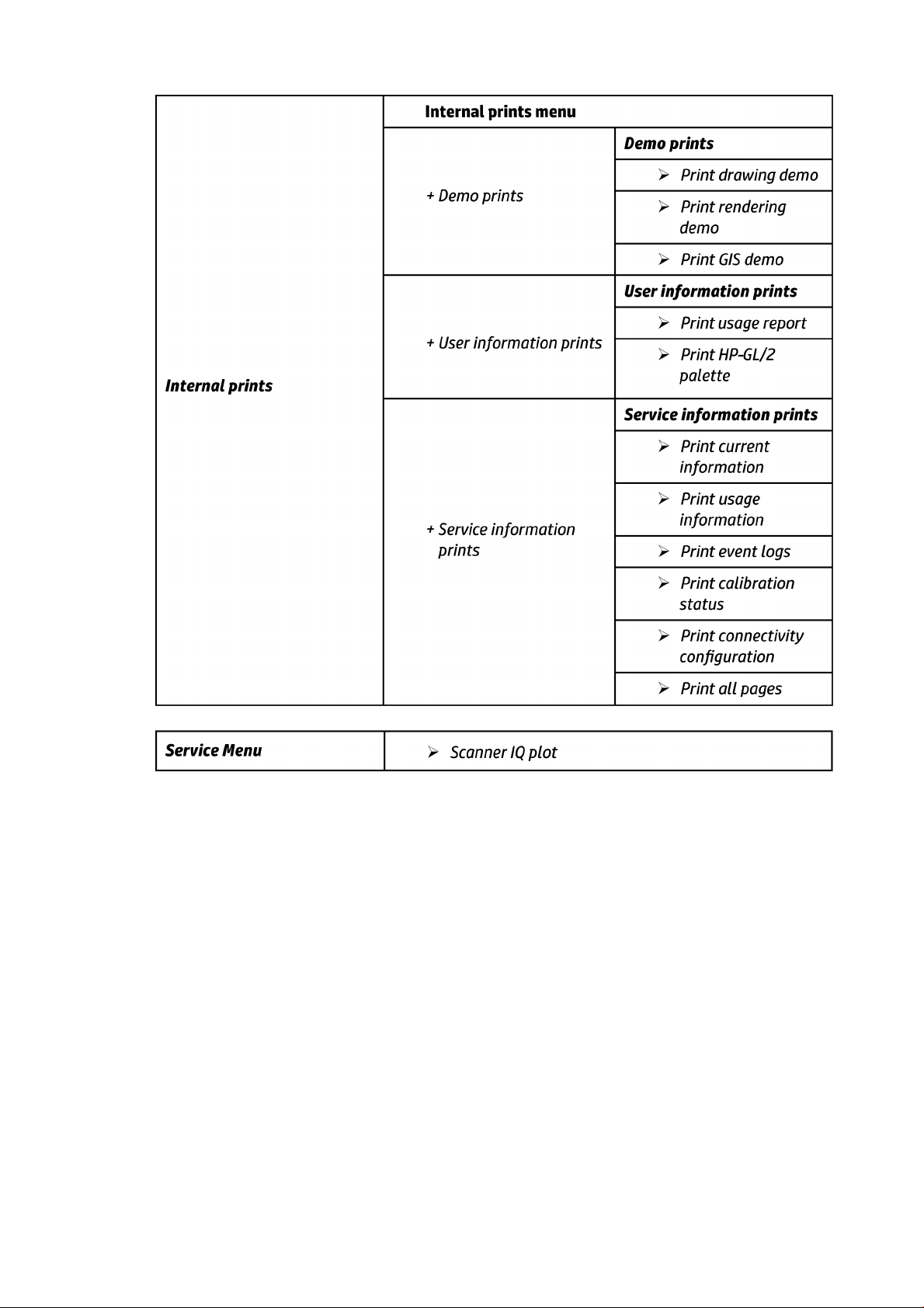
Front Panel Menu Map
The following tables show the front panel menu layout.
14 Chapter 1 Printer fundamentals ENWW
Page 22

ENWW Theory of operation 15
Page 23

16 Chapter 1 Printer fundamentals ENWW
Page 24

ENWW Theory of operation 17
Page 25

18 Chapter 1 Printer fundamentals ENWW
Page 26

ENWW Theory of operation 19
Page 27

20 Chapter 1 Printer fundamentals ENWW
Page 28

ENWW Theory of operation 21
Page 29

22 Chapter 1 Printer fundamentals ENWW
Page 30

ENWW Theory of operation 23
Page 31

24 Chapter 1 Printer fundamentals ENWW
Page 32
ENWW Theory of operation 25
Page 33

Front Panel Menu Map (T3500 only)
26 Chapter 1 Printer fundamentals ENWW
Page 34

HP 727 PH Start-up process
1. Insert cartridges: If the printhead is initialized during the installation of the printer, the printer will first
check for new supplies.
“Ink cartridge missing. Install ink cartridge.”
ENWW Theory of operation 27
Page 35

”Change cartridges now. Press OK to continue.”
If the printer still needs to purge the ink tubes and there are cartridges already installed in it, the printer
will reject the supplies, reporting them as “Not Valid” and will request to “remove and reinsert” the
supplies. Cartridges can be reseated in order to be accepted by the printer before the tubes are purged.
This allows the printer to do a full validation of the supply before running a tube purge.
If the cartridges used for installation do not contain the required 60cc of ink for purging, the printer will
report that “cartridge is not valid for setup”.
NOTE: keep in mind that to initialize a printhead you need 40ml of Matte Black ink and 30ml of ink for
the rest of the colors. To purge ink tubes, you need 60cc of all colors. If in doubt, use 130ml cartridges.
2. After inserting the cartridges, the printer requests the printhead.
“Preparing for printhead replacement”
“Open window to access printheads or press Cancel to quit”
NOTE: If printhead insertion is completed during printer installation, remember to remove the orange
caps.
28 Chapter 1 Printer fundamentals ENWW
Page 36

3. After inserting the printhead, the printer will check electronic connections. If the check fails, the printer
will ask to reseat the printhead.
“Checking printheads. Please wait”
4. Once it is certain that the printhead is recognized, the printer will purge the ink tubes if they are empty.
It will also fill the printhead.
“Preparing the printhead for first usage”
If the process finishes OK, the printer will flag the printer tubes and printhead as filled with ink.
If during the process the printer detects that a cartridge has been removed it will show the message “A
supply has been removed” and it will go back to step 1.
After this step, all ink tubes should be completely filled. The circles on top of the printhead should also
look filled.
5. At this point, the printer will run 2 checks to validate the start-up: first will check for ink pressure and
second for printhead temperature while spitting. If the pressure fails, it will be logged as a SE 93.0.n:10
in the service plot (where n is the failing color). If the temperature check fails, it will be logged as a SE
93.2.n:10 in the service plot (where n is the failing color). The SE are not shown in the front panel. In
both cases, the printer will request to Reseat the printhead. After the reseat the printer will try to fill
again the tubes and ph by going to step 3.
n indicates the missing color:
●
n=0 stands for photo black
●
n=1 stands for gray
●
n=2 stands for matte black
●
n=3 stands for cyan
●
n=4 stands for magenta
●
n=5 stands for yellow
6. After this second trial, the pressure and temperature tests will be repeated. If the pressure fails, it will
be logged as a SE 93.1.n:10 in the service plot (where n is the failing color). If the temperature check
fails, it will be logged as a SE 93.3.n:10 in the service plot (where n is the failing color). The SE are not
shown in the front panel. In any case, the printer will move to step 3 and try to execute it.
ENWW Theory of operation 29
Page 37

7. After the printhead and tubes are filled, the printer completes some printhead servicing to finalize the
initialization.
“Preparing print system”
If successful. If the printhead is properly initialized, the printer shows the following message:
“Printhead replacement. Printhead successfully replaced. Press OK to continue.”
If unsuccessful. If there is a problem the printer, depending on the problem, one of the two following
messages appears:
“Replace printhead. The printhead failed to complete the replacement process. Replace printhead.
Press OK to continue with printhead replacement.”
“Reseat the printhead. Press OK to continue.”
CIS Technology
Example of a CIS Element, Contact Image Sensor:
30 Chapter 1 Printer fundamentals ENWW
Page 38
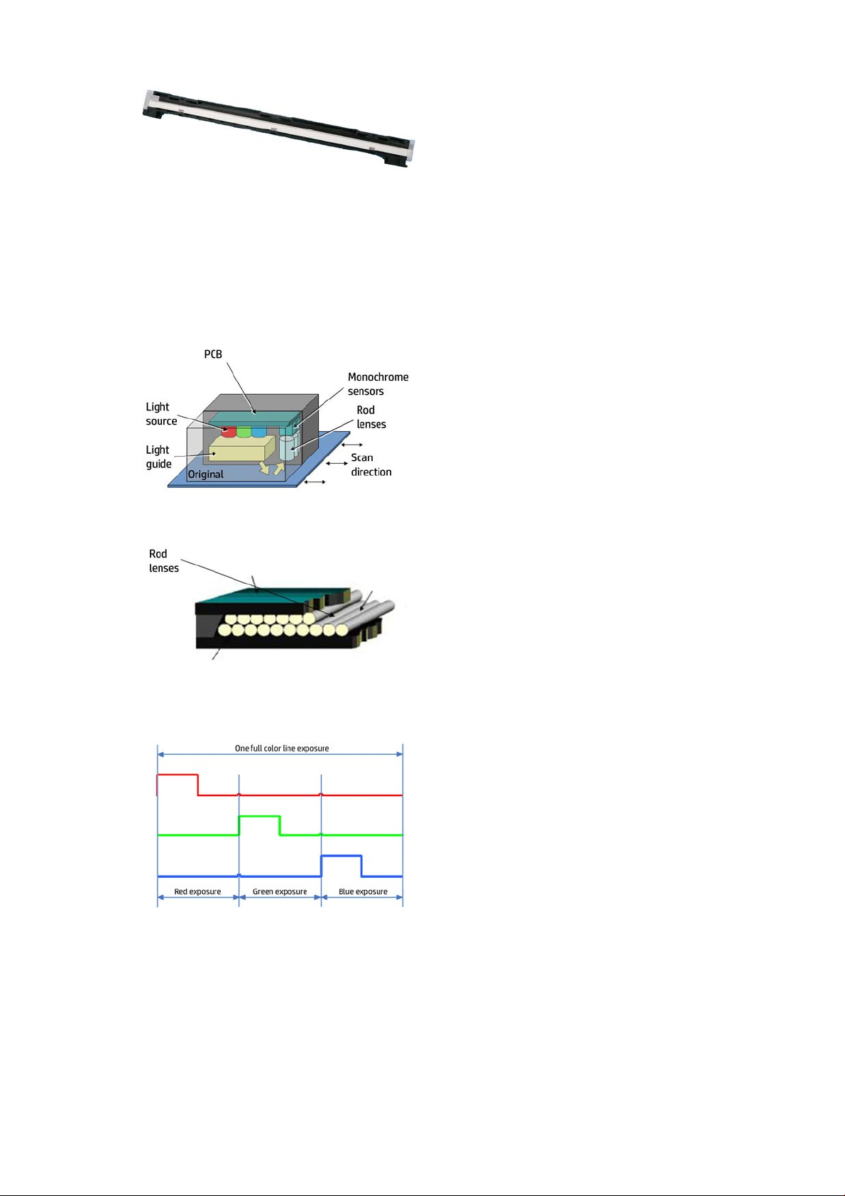
The CIS Element consist of 3 major parts:
●
Sensor
●
Lens
●
Light source
The Light source is 3 RGB LEDs that are lit one at a time. The sensor consists of 10368 individual
monochrome sensors.
The purpose of the lens is to channel the light from the “pixels” on the image to the sensors. There is no
magnification in the lens (1x1).
Due to the very short focal length, the focus depth is limited. The original has to be in contact with the
surface of the glass plate in order to be in focus.
The LED’s flash one at a time, capturing one color at a time.
ENWW Theory of operation 31
Page 39

2 Troubleshooting
●
The front panel
●
Service keys combination
●
Troubleshooting tree (T920 and T1500 only)
●
Product Troubleshooting trees (T2500 and T3500 only)
●
Scanner Troubleshooting Tree
●
Scanner CIS Troubleshooting
●
Paper handling problems
●
Ink supply problems
●
Print-quality problems
●
Connectivity problems
●
Scanning Problems
●
Firmware upgrades
The front panel
The front panel is located on the front right of the printer. It gives you complete control of your printer: from
the front panel, you can print, view information about the printer, change printer settings, perform
calibrations and tests, and so on. The front panel also displays alerts (warning and error messages) when
necessary.
For more information about front panel, refer to the users guide.
32 Chapter 2 Troubleshooting ENWW
Page 40

Sleep mode
Sleep mode puts the printer into a reduced power state after a period of inactivity, turning off the front panel
display to save energy. Printer features can be enabled from this mode, and the printer maintains network
connectivity, waking up only as necessary. The printer can be woken from sleep mode by the Power button,
by sending a print job, or by opening the window, the roll cover, or the stacker cover. The printer wakes up in
several seconds, more quickly than if it is completely turned off. While in sleep mode, the Power button
blinks.
To change the time that elapses before sleep mode, press , then , then Setup > Front panel
options > Sleep mode wait time. You can set a time between 1 and 240 minutes; the default time is 30
minutes.
Printer Monitoring (with thde Print Spooler) and Remote Printer Management with the HP Utility and Web
JetAdmin continue to be available during sleep mode. Some remote management tasks offer the option of
remotely waking up the printer if needed to perform the task.
Other Power States
Besides sleep mode, the printer has 5 different power states (including ready and sleep). Depending on the
power state, the printer has different subsystems wake up and ready for use.
(1) After 50 cycles of sleep-mode, the printer performs an auto-reboot, done between 22h00 and 06h00.
Background information
* Assumes printer is never switched off.
** Total DECC equiv. CO2 footprint of all IB during 5 years May-2013 / May-2018 assuming 20%, switches-off
printer or office power and 33% programs schedule on/off.
ENWW The front panel 33
Page 41

Auto-off
Auto-off sets the printer to "soft-off" mode after the period of time set by the user can in the Front Panel.
This feature is disabled when the printer is connected to the LAN, and in this case, the printer can't go to softoff automatically. The default value from factory for the Auto-off time out is 120min.
NOTE: In some situations this can be confusing since printers without LAN will be set to off automatically
during the night. Furthermore, once the printer has been switched off automatically it needs to be turned on
with the Blue Power Button on the printer. Switching on from the rear button will not wake up the printer.
34 Chapter 2 Troubleshooting ENWW
Page 42

Service keys combination
Entering the diagnostics menu
1. Make sure the product is switched off with the Power button on the side of the Front Panel, and not with
the power switch on the back of the product.
2. Press and release the Power key to switch on the product.
3. Wait for the Home button light to come on.
4. Press the Home button; the button will acknowledge by blinking.
5. All LEDs will come on; press and release them one after another:
●
The Cancel icon
●
The Home icon
●
The Help icon
NOTE: Do not push the icons all at the same time, push each one in the order shown above and
release each icon before pressing on the next icon
6
. The 6 buttons on the Front Panel then blink 4 times; wait until the product completes the initialization
sequence and shows the Diagnostics menu.
7
. In the Diagnostics menu, scroll up and down sliding a finger vertically on the Front Panel, and press on
the desired option.
NOTE: The Diagnostic Tests and Utilities work in a special mode that does not require the full initialization
of the product. Therefore, whenever a test is finished a test, switch off the product and switch it on again
before printing, or executing another test.
NOTE: A quick press of a button on the Front Panel frame may not be recognized by the product. When
pressing a button, be sure to press it for about 1 second.
NOTE: If the product hangs up during a test; switch the product off and restart from step 1.
Entering the service utilities menu
. From the home screen, select the Information icon in the top left corner. For information about the
1
Front Panel keys, see using
2. From the product information area, press the main menu / tool icon on the bottom right corner of the
screen.
. Scroll down to the lowest menu option and select the Service menu option.
3
. Enter the 4-digit 1st level access code “3174” and press OK.
4
. Select the Service utilities menu option.
5
The front panel on page 32 or:
. From the service utilities menu you can scroll up and down to see all the available utilities. Press on the
6
selected menu option.
ENWW Service keys combination 35
Page 43

Troubleshooting tree (T920 and T1500 only)
As a general approach, the following tree should be followed to troubleshoot any issue. This helps
understand at which point the problem was caused. The tree is sequential; before checking a subsystem, the
previous steps need to be working. Once a sub system is identified as causing the problem, the service and
utilities related to that component can be used to troubleshoot further. See Diagnostics, Service Utilities and
Calibrations on page 132.
36 Chapter 2 Troubleshooting ENWW
Page 44

NOTE: Once an issue is confirmed, check that printer has latest firmware installed.
ENWW Troubleshooting tree (T920 and T1500 only) 37
Page 45

Product Troubleshooting trees (T2500 and T3500 only)
Figure 1-1 Troubleshooting
38 Chapter 2 Troubleshooting ENWW
Page 46

Scanner Troubleshooting Tree
Figure 1-2 Scanner Troubleshooting
ENWW Scanner Troubleshooting Tree 39
Page 47

Scanner CIS Troubleshooting
Figure 1-3 Scanner Troubleshooting
40 Chapter 2 Troubleshooting ENWW
Page 48

Paper handling problems
●
The paper has jammed in the print platen
●
The paper has jammed in the stacker
●
Thin paper is jamming in the stacker
●
High density plots jamming in the stacker
●
Stacker capacity lower than expected
●
The stacker detects "Stacker is full" permently
●
The printer rejects the paper during paper load
●
Prints do not fall neatly into the basket
●
The paper type is not in the list
●
The printer printed on the wrong paper type
●
An “on hold for paper” message
●
The printer displays out of paper when paper is available
●
The print remains in the printer after printing has completed
●
The cutter does not cut well
●
The roll is loose on the spindle
The paper has jammed in the print platen
When a paper jam occurs, you normally see the Possible paper jam message in the front panel display, and a
system error 81:01 or 86:01.
1. Open the window.
ENWW Paper handling problems 41
Page 49

2. Move the carriage manually to the left side of the printer, if feasible.
3. Go to the paper path.
4. Cut the paper with a pair of scissors.
42 Chapter 2 Troubleshooting ENWW
Page 50

5. Open the roll cover.
6. Manually rewind paper onto the roll.
ENWW Paper handling problems 43
Page 51

7. If the leading edge of the paper is ragged, trim it carefully with scissors.
NOTE: In the T3500 the guide can be used for cutting.
. Remove the paper left in the printer.
8
44 Chapter 2 Troubleshooting ENWW
Page 52

9. Make sure you have removed every fragment of paper.
10. Close the window and the roll cover.
11. Restart the printer by holding down the power button for a few seconds, or by turning the power switch
at the rear off and then on.
12. Reload the roll, or load a new sheet.
NOTE: If you find that there is still some paper causing an obstruction within the printer, restart the
procedure and carefully remove all pieces of paper.
The paper has jammed in the stacker
When a stacker jam is detected, printing is paused, and the front panel asks you to open the stacker cover
and clear the jam by pulling out the paper.
When the stacker cover is closed and the printer detects no jammed paper, the front panel requests
confirmation to continue printing.
Thin paper is jamming in the stacker
When using a media thinner than 75gsm, the blue lever needs to be pulled forwards so that there is a larger
gap between the arms and stacker tray when the arms are closed.
ENWW Paper handling problems 45
Page 53

After printing with thin media, remember to return the blue lever so that there is a small gap between the
arms and stacker tray.
High density plots jamming in the stacker
If you are printing high-density plots (over 15ngrs ink density) with media below 80grs/m2, and you
encounter that plots have problems curving at the end of the stacker, or do not stack properly, and cause
jams:
●
Use Manual mode.
●
Print to the basket.
●
Use thicker media; over 80grs/m2.
46 Chapter 2 Troubleshooting ENWW
Page 54

Stacker capacity lower than expected
Stacker capacity is defined as up to 50 pages (T920/T1500/T2500), and 100 pages (T3500), A1/D size line
drawing plots in landscape on bond media, but stacker capacity depends on media thickness and page size. If
you are printing plots shorter than A1 and you experience a reduction in the stacker capacity because they
collapse and the curling fills the available stacking space:
●
Try to increase the length of the plots when printing A2 and A3 sizes:
◦
Print A2 sizes in portrait position, using low-width rolls or nesting to minimize waste of paper.
◦
For A3 size, group different jobs in the same plot.
The stacker detects "Stacker is full" permently
Even when there are no pages in the stacker, it detects that is it full.
●
Run the capacity sensor diagnostic.
●
Run the ramps motor diagnostic.
●
Check that when the ramps are up all are at the same height.
The printer rejects the paper during paper load
If the roll load process is too long and unsuccessful, check the following items:
●
Roll paper is properly inserted in the spindle and pressed uniformly by the hubs.
●
The core of the roll paper is not misplaced. If this is the case, try to correct its position.
●
Check if the black hub of the spindle is damaged. If any part of the spindle is damaged, it could cause
roll load problems.
Prints do not fall neatly into the basket
●
Ensure that the network and power cables are not getting in the way.
●
Ensure that the basket is correctly installed.
●
Ensure that the basket is open.
ENWW Paper handling problems 47
Page 55

●
Ensure that the basket is not full.
●
Ensure that the paper is not jammed.
●
Paper often tends to curl near the end of a roll, which can cause output problems. Load a new roll, or
remove prints manually as they are completed.
If you see the message Please remove the print from the basket and press OK to continue, empty the
basket, check that there is no paper in the path to the basket, then press OK. The printer checks that the
problem has been fixed.
The paper type is not in the list
To work with a paper that does not appear in the list in the driver or front panel, you can choose one of the
other papers in the list. However, you should at least choose a paper of the same type: transparent or
translucent, photo or bond, coated or technical.
NOTE: For photo paper, it is important to select a photo paper type, as the printer adjusts its use of ink for
photo paper.
Transparent or translucent film
If your paper is a transparent film (for example, a transparency), select paper type Film > Transparent/Clear
film.
If your paper is a translucent paper or film (for example, technical paper), select paper type Film > Matte
film.
Photo paper
If your paper is a photo paper, use the Photo Paper category. For gloss or high-gloss paper, select paper type
Photo Gloss Paper. For semi-gloss, satin, pearl, or luster finishes, select paper type Photo Semi-gloss/Satin
Paper.
To increase gamut on photo paper, select paper type HP Universal Gloss Photo Paper or HP Universal Satin
Photo Paper, depending on the finish.
Bond and coated or technical paper
Your paper type selection for generic paper depends on the paper’s ink absorption capacity.
●
For thin papers (< 90 g/m2) or uncoated papers (for example plain paper or bright white paper), select
paper type Bond and Coated Paper
●
For light coated papers (< 110 g/m2), select paper type
●
For heavyweight coated papers (< 200 g/m2), select paper type Bond and Coated Paper > Heavyweight
Coated Paper
.
Black ink is easily removed when touched
This happens when your paper is incompatible with matte black ink. To use an optimized ink combination,
select paper type Photo Paper > Photo Gloss Paper.
> Plain Paper. You can also select Recycled Bond Paper.
Bond and Coated Paper > HP Coated Paper.
After printing, the paper has wrinkles or there is too much ink
Reduce the quantity of ink, or use thicker paper. Matte paper categories from thinnest to thickest are:
●
Plain Paper
●
Coated Paper
48 Chapter 2 Troubleshooting ENWW
Page 56

●
Heavyweight Coated Paper
●
Super Heavyweight Plus Matte Paper
TIP: If you load paper that is slightly thicker than the paper type you selected, the printer will use less ink
than usual for the loaded paper.
The printer printed on the wrong paper type
If the printer prints your job before you were able to load your desired paper, you may have Any or Use
printer settings selected for the Paper Type in the printer driver. In this case, the printer will print
immediately on whichever paper is loaded. Load your desired paper, and select your paper type specifically in
the driver.
●
In the Windows driver dialog: select the Paper/Quality tab, then select your paper type from the Paper
Type list.
●
In the Mac OS X Print dialog: select the Paper/Quality panel, then select your paper type from the
Paper Type list.
NOTE: The driver default is Any for Mac OS and Use printer settings for Windows; they have the same
effect.
An “on hold for paper” message
Based on a set of conditions that you can set when sending a job to a two-roll printer, the printer will decide
which of the loaded rolls of paper is more suitable to print the job. If there is no roll of paper available that
meets all the conditions, the printer will put the job on hold for paper. You can manually resume the job,
forcing it to print on a paper other than the one originally specified, otherwise it will stay on hold.
Which criteria are used to decide on which roll a job will be printed?
When a user sends a job, the desired paper type can be set (in the driver or in the Embedded Web Server). The
printer will print the job on a roll of paper of the chosen paper type that is large enough to print the drawing
without clipping. If there is more than one roll on which the job could be printed meeting all the criteria, the
roll will be chosen according to your preferences. These can be set from the front panel.
When is a job put on hold for paper?
If the paper mismatch action is set to Put job on hold, a job is put on hold for paper in the following cases:
●
The paper type that has been selected by the user is not currently loaded on the specified roll—or on
either of the rolls, if no roll has been specified.
●
The paper type that has been selected by the user is loaded on the specified roll, but the drawing is too
large to fit on the roll—or on either of the rolls, if no roll has been specified.
If I load a new roll of paper, will jobs that were on hold for paper be automatically printed?
Yes. Every time a new roll of paper is loaded, the printer will check if there are any jobs on hold for paper that
could be printed on the loaded roll.
I don’t like jobs being put on hold for paper. Can I prevent it?
Yes, this can be done from the front panel.
ENWW Paper handling problems 49
Page 57

I set the option “Paper mismatch action” to “Print anyway”, but some jobs are still put on hold
(Windows driver only)
If the Show print preview option is selected in the driver or the Embedded Web Server, jobs are put on hold
until you have checked the preview and resumed the job. Check that the Show print preview option is not
checked in the driver, and that there are no pending preview windows waiting for confirmation to continue
printing.
My job is exactly as wide as the roll of paper that is loaded on the printer, but is put on hold for
paper
Margins are managed in different ways depending on the file type:
●
For HP-GL/2 and HP RTL files, by default, margins are included inside the drawing, so a 914 mm (36 in)
HP-GL/2 and HP RTL file can be printed on a 914 mm (36 in) roll of paper and will not be put on hold for
paper.
●
For other file formats, such as PostScript, PDF, TIFF or JPEG, the printer assumes that margins need to
be added outside the drawing (as, in many cases, these formats are used for photographs and other
images that do not include margins). This means that, to print a 914 mm (36 in) TIFF, the printer needs
to add margins, and the drawing needs 925 mm (36.4 in) of paper to be printed; this would cause the job
to be put on hold if the paper that is loaded on the printer is only 914 mm (36 in) wide.
If you wish to print these file formats without adding extra margins outside of the drawing, the Clip
contents by margins option can be used. This option will force the margins to be set inside of the
drawing, so a 914 mm (36 in) TIFF can be printed on a 914 mm (36 in) roll of paper without being put on
hold. However, if there is no white space already included in the drawing’s borders, some contents could
be clipped because of the margins.
NOTE: If you choose the option Match exact size, your job will be printed only on paper whose width
exactly matches the width of the job.
The printer displays out of paper when paper is available
If the roll has become loose from its core, it will not feed correctly and the printer will not load the paper. If
possible, tighten the paper to its core or load a new roll.
The print remains in the printer after printing has completed
The printer holds the paper to allow the print to dry after printing. If a sheet of paper is only partially ejected
after the drying time, gently pull it out of the printer.
The cutter does not cut well
By default, the printer is set to cut the paper automatically after each job.
If the cutter is turned on but not cutting correctly, check that the cutter rail is clean and clear of any
obstacles.
Even if the cutter is set to Off, the printer will still cut while:
●
Switching from Roll 1 to Roll 2 or viceversa
●
Switching the output from Stacker to Basket, and viceversa
If the cutter is not cutting, check that the carriage engages properly with the cutter actuator in order to
activate it.
●
Launch printhead replacement.
●
Power of the printer with the rear power switch when the carriage is in the middle of the printer.
50 Chapter 2 Troubleshooting ENWW
Page 58

●
At this point, the cutter should be activated.
●
Move the carriage manually to the service station side end to disengage the cutter.
●
Move the carriage manually to the Front panel side end to engage it again.
●
Notice the noise made by the engagement/disengagement, and also that the carriage friction is higher
when the cutter is engaged.
●
Finally, move the carriage manually to the service station side end to disengage the cutter.
●
Power on the printer.
Finally, if code SE86:01 appears while cutting, it may be required to manually readjust the Encoder Strip and
move it up slightly.
The roll is loose on the spindle
The roll may need to be replaced or reloaded.
ENWW Paper handling problems 51
Page 59

Ink supply problems
●
Cannot insert an ink cartridge
●
Ink cartridge status messages
●
Cannot insert the printhead
●
The front panel display recommends reseating or replacing the printhead
●
Clean the printhead
●
Align the printhead
●
Printhead status messages
●
PH 727 Error codes
Cannot insert an ink cartridge
1. Check that you have the correct type of cartridge (model number).
2. Check that the colored label on the cartridge is the same color as the label on the slot.
3. Check that the cartridge is correctly oriented, with the letter or letters marking the cartridge label right-
side up and readable.
CAUTION: Never clean inside the ink cartridge slots.
Ink cartridge status messages
These are the possible ink cartridge status messages:
●
●
●
●
●
●
●
●
●
●
: The cartridge is working normally, with no known problems.
OK
Missing
Low
Very low
Empty
Reseat
Replace
Expired
Incorrect
cartridges.
Non-HP
: There is no cartridge present, or it is not correctly connected to the printer.
: The ink level is low.
: The ink level is very low.
: The cartridge is empty.
: You are recommended to remove the cartridge and then reinsert it.
: You are recommended to replace the cartridge with a new cartridge.
: It is past the cartridge's expiration date.
: The cartridge is not compatible with this printer. The message includes a list of compatible
: The cartridge is used, refilled, or counterfeit.
●
Not Valid: If the printer doesn't have enough ink to perform an operation, it will display the front panel
message “Not Valid For Operation”. In order to remove the messag,e a cartridge containing more ink is
needed.
52 Chapter 2 Troubleshooting ENWW
Page 60

Cannot insert the printhead
1. Check that you have the correct type of printhead (model number).
2. Check that the printhead is correctly oriented.
3. Check that you have correctly closed and latched the printhead cover.
The front panel display recommends reseating or replacing the printhead
1. The printer rebooted during the start-up; printhead initialization took a long time and was then
canceled.
Root Cause
●
Printhead issue.
●
Incorrect error message from drop detection that causes the printer to carry out additional
servicing routines.
●
Other issues.
Corrective action
●
Do not stop the servicing routines, allow the printhead to be initialized.
●
If, after the start-up, the image quality is poor, carry out the usual image quality troubleshooting.
2. The carriage does not close fully; it appears to be closed, but the blue latch sticks up a little and does
not stay flat.
How to check:
If the carriage latch is not closed properly, it is very important to ensure that:
a. The carriage latch is properly engaged.
ENWW Ink supply problems 53
Page 61

b. The latch is completely down.
If these two conditions are not met, printhead installation may fail and/or some tubes may not be filled
with ink.
NOTE: If the carriage is open, it will be detected by the printer and the customer will be asked to try to
close it again. However, if the carriage is not closed and the printer is powered off, there is a risk that,
after booting up, the printer will raise service system error 86:01. In this case, turn the printer off again,
close the carriage (removing the printhead, if necessary), and then move the printhead to the Service
Station. Finally boot up the printer again.
Root Cause
Incorrect printhead insertion can cause errors because of insufficient lubrication or the latch not
engaging properly.
Corrective action
For printers with serial numbers CN35xxxxxx, CN36xxxxxx, CN37xxxxxx, CN38xxxxxx, SG35xxxxxx,
SG36xxxxxx, SG37xxxxxx, or SG38xxxxxx, the tube connectors can be lubricated by moistening with
water to help with the insertion of the printhead. This can be done as follows:
a. Moisten a soft cloth with water.
54 Chapter 2 Troubleshooting ENWW
Page 62

b. Open the carriage latch completely.
c. Use the wet cloth to moisten the septum.
d. Try to close the carriage latch again. If necessary, push against the rear side of the carriage to
ensure it is properly closed.
ENWW Ink supply problems 55
Page 63

3. ALL ink tubes are empty, or the printhead is rejected immediately after insertion and no tubes start to
fill. The printer brings the printhead to the Service Station and rejects it immediately.
How to check:
In some of these cases the printer will show Front Panel printhead error Code 0x00002.
When visually checking the tubes:
a. Open the carriage.
b. Check the end of the tubes. They should appear as shown in the picture below. The rest of the ink
circuit can be checked for bubbles and ink. When the tubes are empty, they will have a bluish color.
When filled, the tubes will look darker and the yellow channel will have a slight magenta color (due
to the combination of ink color and tube color).
Filled tubes:
Empty tubes:
Root Cause
If the printer rejects the printhead before even trying to initiate tube purging, it can indicate that the
printer does not recognize the printhead. This may also cause a 0x00002 Front Panel printhead Error
Code.
Corrective action
First, try using a different printhead. If the replacement printhead still fails, the issue can be due to the
Carriage PCA.
4. The printhead is rejected and some ink tubes are not filled: Yellow and Matte Black are missing, or Cyan,
Magenta, Gray, and Photo Black are missing.
Root Cause
56 Chapter 2 Troubleshooting ENWW
Page 64

There are two primer channels. Yellow and Matte Black share one primer channel. Cyan, Magenta, Gray,
and Photo Black share the other primer channel. If one primer fails, one of the groups might not get
filled.
Corrective action
Run the primer test to check if the primer is working. If it fails, replace the primer. Also, ensure that the
ink tube connectors are properly lubricated. Run a tube purge to fill all the tubes, including the missing
color. To purge the tubes, first remove all supplies (ink and printhead). Then run “Purge tubes” from the
service utilities. Re-insert the inks and printhead, as requested.
NOTE: If a cartridge is inserted and the ink tube is not filled, the printer can potentially mark the
cartridge as “Out Of Ink”. To prevent this from happening, do not install cartridges when some tubes are
empty.
5. The printhead is rejected and some of the ink tubes are not filled: Gray, Photo Black, & Matte Black, or
Cyan, Magenta, & Yellow are missing.
Root Cause
The Ink Supply Station has separate System Errors from the printhead. However, if the missing colors
are grouped as they are in the Ink Supply Station, this issue can be related to that part of the printer.
Corrective action
Run the “Ink Delivery System diagnostic” to check the status of the Ink Supply Station and troubleshoot
accordingly. Also, ensure that the ink tube connectors are properly lubricated. Run a tube purge to fill
all the tubes, including the missing color. To purge the tubes, first remove all supplies (ink and
printhead). Then run “Purge tubes” from the service utilities Re-insert the inks and printhead, as
requested.
6. The printhead is rejected, and some ink tubes are not filled: any other color combination.
Root Cause
If only one tube is empty, any of the aforementioned root causes may apply.
Corrective action
Test the primer and Ink Supply Station. Ensure the ink tube connectors are properly lubricated. Run a
tube purge to fill all the tubes, including the missing color. To purge the tubes, first remove all supplies
(ink and printhead). Then run “Purge tubes” from the service utilities. Re-insert the inks and printhead,
as requested.
7. The printhead shows error code 0x00002, 0x02000, or 0x04000.
Root Cause
The printer is not able to communicate with the printhead.
Corrective action
First, try using a new printhead. If the error continues, try a new carriage PCA.
8. The printhead shows an Error Code 0x00010 or 0x00040.
Root Cause
The nozzle area is overheating. This can be due to air present in the nozzle area of the printhead.
Corrective action
Check that the ink tubes are filled and have no air bubbles. Run manual printhead cleaning to try to
restore the printhead. Ultimately, replace the printhead if needed.
ENWW Ink supply problems 57
Page 65

9. All ink tubes are filled, but the printer requests a random printhead reseat..
Root Cause
To analyze the root cause, check the printhead Error Code in the table at the end of this document.
Corrective action
The printhead reseat issue can be solved by simply removing and reinstalling the printhead. If, after the
reseat, the error message continues, try a new printhead. If the reseat message continues to appear,
check the carriage PCA using the Carriage test in the diagnostic menu.
10. During printer installation troubleshooting, the printer asks if the printhead to be used is “New” or
“Reused”.
Root Cause
Depending on the situation, when trying to replace the printhead with a new one, the printer can ask if
the printhead that is going to be used is “New” or “Reused”. For instance, this can happen when the ink
tubes are filled, but the printhead installation fails during the servicing routines.
Corrective action
If doing a reseat of the old printhead, the “Reused” option should be selected. The “New” option should
only be selected if the printhead that is going to be used needs to be filled with ink. When “New” is
selected, the printer will check if there is enough ink to run the new printhead installation. If there is not
enough ink, the printer will only carry out the servicing routines to prepare the printhead.
Clean the printhead
As long as the printer is kept turned on, automatic cleaning is performed periodically. This ensures there is
fresh ink in the nozzles and prevents nozzle clogs, thus preserving print quality. If you have print quality
problems, please see Print-quality problems on page 61 before proceeding.
To clean the printhead, go to the front panel and press , then , then Image Quality Maintenance
> Clean printhead, and select the color group including the color that needs cleaning (Clean all, Clean MK-Y,
Clean C-M-PK-G).
Align the printhead
Precise printhead alignment is essential for accurate colors, smooth color transitions, and sharp edges in
graphical elements. Your printer has an automatic printhead alignment process which runs whenever the
printhead has been accessed or replaced.
You may need to align the printhead after a paper jam or if you are experiencing print-quality problems.
1. Load the paper you wish to use. You can use a roll or a cut sheet; plain white paper is recommended.
CAUTION: Do not use transparent or semi-transparent paper to align the printhead.
. Ensure that the window is closed, as a strong light source near the printer during printhead realignment
2
can affect alignment.
.
3
From the front panel, press
, then Image Quality Maintenance >
Align printhead
.
NOTE: Printhead alignment can also be started from the Embedded Web Server (
Quality Troubleshooting), or from the HP Utility (Windows: Support > Print Quality Troubleshooting;
Mac OS X: Information and Print Quality > Align).
58 Chapter 2 Troubleshooting ENWW
Support > Print
Page 66

4. If the loaded paper is satisfactory, the printer runs the realignment and prints a realignment pattern.
5. The process takes about five minutes. Wait until the front panel display shows the process complete
before using the printer.
If the printer cannot complete the printhead alignment successfully, you may be asked to clean the printhead
and try again.
Printhead status messages
These are the possible printhead status messages:
●
OK: The printhead is working normally, with no known problems
●
Missing: There is no printhead present, or it is not correctly installed in the printer.
●
Reseat: You are recommended to remove the printhead and then reinsert it. If that fails, clean the
electrical connections, see The front panel display recommends reseating or replacing the printhead
on page 53. If that fails, replace the printhead with a new one.
●
Replace: The printhead is failing. Replace the printhead with a working one.
●
Replacement incomplete: The printhead replacement process has not completed successfully; relaunch the replacement process and let it finish completely.
●
Remove: The printhead is not a suitable type for use in printing.
●
Non-HP ink: Ink from a used, refilled, or counterfeit ink cartridge has passed through the printhead. See
the limited warranty document provided with your printer for details of the warranty implications.
PH 727 Error codes
How to check the printhead error code:
●
Generate the Service plot. Go to the Embedded Web Server: Support tab > Service support > Printer
informationn. This will open a new page. Select the All pages tab. Download this page or print it to a
PDF file.
●
Alternatively, check the printhead “Status” in the Front Panel.
PH 727 error codes:
The following table lists the potential error codes reported by the printer:
ENWW Ink supply problems 59
Page 67

Status / Failure
mode
WORKING OK 0 0x00000 The pen is working properly
FAILS_LOGICAL_V RESEAT 1 0x00001 Under-voltage, over-voltage or ink shortage detected in Vcc (5V)
FAILS_CONTINUITYRESEAT 2 0x00002 Failed pen ID programming or pen continuity tests
SHUTDOWN REPLACE 4 0x00004 CsData fault, printhead clock or temperature error
FAILS_VPP RESEAT 8 0x00008 Under-voltage, over-voltage, leakage or ink shortage detected in Vpp
Action
reported
to user
Service
Support /
Printer
Informatio
n Code by
EWS
Printhead
Informatio
n by
Control
Panel
Description
or VppLogic
TEMP_EXTREMEL
Y_HIGH
TEMP_EXTREMEL
Y_LOW
TEMP_TOO_HIGH RESEAT 64 0x00040 The temperature of the pen has been above the normal margins for
TEMP_TOO_LOW RESEAT 128 0x00080 The temperature of the pen has been below the normal margins for
BAD_ACUMEN_INFOREPLACE 256 0x00100 Parity error on printhead bits
NO_PEN MISSING 512 0x00200 There is no pen detected
BAD_ACUMEN_AC
CESS
WRONG_MODEL REMOVE 2048 0x00800 The model inserted is not the model required by the printer
MISMATCH REMOVE 4096 0x01000 The color or the printhead version is not in the required slot
CSDATA_NOT_RE
SPONDING
CSDATA_TRANSM
IT_ERROR
EXPIRED_WARRA
NTY
REPLACE 16 0x00010 The temperature of the pen is beyond maximum margin
REPLACE 32 0x00020 The temperature of the pen is under minimum margin
too long
too long
RESEAT 1024 0x00400 Error while reading or writing printhead bits
RESEAT 8192 0x02000 The CSDATA communication failed
RESEAT 16384 0x04000 The CSDATA communication failed
— 524288 0x80000 The printhead is ok but failed the warranty validation
60 Chapter 2 Troubleshooting ENWW
Page 68

Print-quality problems
●
General advice
●
Print-quality troubleshooting wizard
●
Recalibrate the paper advance
●
Horizontal lines across the image (banding)
●
Lines are too thick, too thin or missing
●
Lines appear stepped or jagged
●
Lines print double or in the wrong colors
●
Lines are discontinuous
●
Lines are blurred
●
Line lengths are inaccurate
●
The whole image is blurry or grainy
●
The paper is not flat
●
The print is scuffed or scratched
●
Ink marks on the paper
●
Black ink comes off when you touch the print
●
Edges of objects are stepped or not sharp
●
Edges of objects are darker than expected
●
Horizontal lines at the end of a cut sheet print
●
Vertical bands of different colors
●
White spots on the print
●
Colors are inaccurate
●
Colors are fading
●
The image is incomplete (clipped at the bottom)
●
The image is clipped
●
Some objects are missing from the printed image
●
A PDF file is clipped or objects are missing
●
The Image Diagnostics Print
●
If you still have a problem
General advice
When you have any print-quality problem:
ENWW Print-quality problems 61
Page 69

●
To achieve the best performance from your printer, use only genuine manufacturer's supplies and
accessories, whose reliability and performance have been thoroughly tested to give trouble-free
performance and best-quality prints. For details of recommended papers, see users guide.
●
Make sure that the paper type selected in the front panel is the same as the paper type loaded into the
printer (see users guide). At the same time, check that the paper type has been calibrated. Also make
sure that the paper type selected in your software is the same as the paper type loaded into the printer.
CAUTION: If you have the wrong paper type selected, you could experience poor print quality and
incorrect colors, and perhaps even damage to the printhead.
●
Check that you are using the most appropriate print-quality settings for your purposes (see users
guide). You are likely to see lower print quality if you have moved the print-quality slider to the 'Speed'
end of the scale, or set the custom quality level to Fast.
●
Check that your environmental conditions (temperature, humidity) are in the recommended range. See
users guide.
●
Check that your ink cartridges and printhead have not passed their expiration dates: see users guide.
For the latest information, please visit http://www.hp.com/go/T920/support or http://www.hp.com/go/
T1500/support.
Print-quality troubleshooting wizard
The print-quality troubleshooting wizard can help with the following problems:
●
Horizontal lines across the image (banding)
●
The whole image is blurry or grainy
●
Lines are too thick, too thin or missing
●
Colors are inaccurate
To start the wizard:
●
From the HP Designjet Utility for Windows: Go to the Support tab, and select Print Quality Toolbox.
●
From the HP Utility for Mac OS X: Select Print quality troubleshooting in the Support group.
●
From the Embedded Web Server: Go to the Support tab, then select Print quality troubleshooting.
●
From the front panel: Press , then , then Image quality maintenance.
Alternatively, or if you have other print-quality problems, you can continue reading this chapter.
Recalibrate the paper advance
Accurate paper advance is important to image quality because it is part of controlling the proper placement
of dots on the paper. If the paper is not advanced the proper distance between printhead passes, light or dark
bands appear in the print and image grain may increase.
The printer is calibrated to advance correctly with all the papers appearing in the front panel. When you
select the type of loaded paper, the printer adjusts the rate at which to advance the paper while printing.
However, if you are not satisfied with the default calibration of your paper, you may need to recalibrate the
rate at which the paper advances. See users guide for steps to determine if paper advance calibration will
solve your issue.
You can check the paper advance calibration status of the currently loaded paper at any time from the front
panel. Press , then , then Image quality maintenance > Calibration status. The status may be
one of the following.
62 Chapter 2 Troubleshooting ENWW
Page 70

●
DEFAULT: This status appears when loading any paper that has not been calibrated. HP papers in the
Front Panel have been optimized by default and unless you experience image quality problems in your
printed image such as banding or graininess it is not recommended to recalibrate the paper advance.
●
OK: This status indicates that the loaded paper has been calibrated before. However you may need to
repeat the calibration if you experience image quality problems such as banding or graininess in your
printed image.
NOTE: Whenever you update the printer’s firmware, the paper advance calibration values are reset to
factory default, see users guide.
CAUTION: Transparent papers and films must be calibrated by pressing , then , then Image
quality maintenance > Paper advance calibration > Adjust paper advance, from step four in Recalibrating
the paper advance procedure.
Recalibrating the paper advance procedure
1.
From the front panel, press , then , then Image quality maintenance > Paper advance
calibration > Calibrate paper advance. The printer automatically recalibrates the paper advance and
prints a paper advance calibration image, which you can send to stacker or basket.
2. Wait until the front panel displays the status screen, then reprint your print.
NOTE: The recalibration procedure takes a few minutes. Do not worry about the paper advance
calibration image. The front-panel display shows any errors in the process.
If you are satisfied with your print continue using this calibration for your paper type. If you see
improvement in your print, continue with step three. If you are dissatisfied with the recalibration, return
to the default calibration, see Return to default calibration on page 64.
3.
If you would like to fine-tune the calibration or are using a transparent paper, press , then ,
then Image quality maintenance > Paper advance calibration > Adjust paper advance.
ENWW Print-quality problems 63
Page 71

4. Select the percentage of change from –100% to +100%. To correct light banding, decrease the
percentage.
To correct dark banding, increase the percentage.
5. Press OK on the front panel, to save the value.
6. Wait until the front panel displays the status screen and reprint your print.
Return to default calibration
Returning to the default calibration sets all the corrections made by the paper advance calibration to zero. To
return to the default paper advance calibration value, you must reset the calibration.
1.
From the front panel, press , then , then Image quality maintenance > Paper advance
calibration > Reset paper advance.
2. Wait until the front panel displays the operation has completed successfully.
Horizontal lines across the image (banding)
If your printed image suffers from added horizontal lines as shown (the color may vary):
64 Chapter 2 Troubleshooting ENWW
Page 72

1
. Check that the paper type you have loaded corresponds to the paper type selected in the front panel
and in your software. See users guide.
2
. Check that you are using appropriate print-quality settings for your purposes (see users guide). In some
cases, you can overcome a print-quality problem merely by selecting a higher print-quality level. For
instance, if you have set the Print Quality slider to Speed, try setting it to Quality. If you change the
print-quality settings, you may wish to reprint your job at this point in case the problem has been
solved.
3
. Print the Image Diagnostics Print. See
4.
If the printhead is working correctly, go to the front panel and press , then , then
quality maintenance > Calibration status to see the paper advance calibration status. If the status is
DEFAULT, try performing paper advance calibration: see
In case you are using rolls with 3-in core adaptors:
1
. Check that the roll core is not damaged.
2
. Make sure that the 3-in adaptor is correctly attached to the spindle.
3
. Print using Roll 1 for better performance.
4
. Print in a higher quality/slower mode.
5
. If horizontal banding is only showing in the laterals of the media, check that the 3-in. adaptors are
positioned so that the spring of the black hub and the blue hub are aligned:
If the problem persists despite all the above actions, contact your customer service representative for
further support.
The Image Diagnostics Print on page 75.
Image
Recalibrate the paper advance on page 62.
ENWW Print-quality problems 65
Page 73

Lines are too thick, too thin or missing
. Check that the paper type you have loaded corresponds to the paper type selected in the front panel
1
and in your software. See users guide.
. Check that you are using appropriate print-quality settings for your purposes (see users guide). If
2
printing on photo paper, select the custom print-quality options in the driver dialog, and try turning on
the Maximum detail option (if available). You may wish to reprint your job at this point in case the
problem has been solved.
. If the resolution of your image is greater than the printing resolution, you may notice a loss of line
3
quality. If you are using the PCL3GUI or the HP-GL/2 driver for Windows, you can find the Max.
Application Resolution option in the driver dialog's Advanced tab, under Document Options > Printer
Features. If you change this option, you may wish to reprint your job at this point in case the problem
has been solved.
. When printing on uncoated paper in Fast mode, try loading the paper as Bright Bond.
4
.
5
If the problem remains, go to the front panel and press
maintenance
should align the printhead. See
your job in case the problem has been solved.
.
6
Go to the front panel and press
status to see the paper advance calibration status. If the status is DEFAULT, you should perform paper
advance calibration: see Recalibrate the paper advance on page 62.
7. If lines are too thin or missing, print the Image Diagnostics Print. See The Image Diagnostics Print
on page 75.
If the problem persists despite all the above actions, contact your customer service representative for
further support.
> Align printhead to see the printhead alignment status. If the status is PENDING, you
Lines appear stepped or jagged
If lines in your image appear stepped or jagged when printed:
, then , then Image quality
Align the printhead on page 58. After alignment, you may wish to reprint
, then , then Image quality maintenance > Calibration
66 Chapter 2 Troubleshooting ENWW
Page 74

1. The problem may be inherent in the image. Try to improve the image with the application you are using
to edit it.
2. Check that you are using appropriate print-quality settings. See users guide.
3. Select the custom print-quality options in the driver dialog, and turn on the Maximum detail option (if
available).
Lines print double or in the wrong colors
This problem can have various visible symptoms:
●
Colored lines are printed double, in different colors.
●
The borders of colored blocks are wrongly colored.
To correct this kind of problem:
1. Align the printhead. See Align the printhead on page 58.
2. Reseat the printhead by removing and then reinserting it. See users guide.
Lines are discontinuous
If your lines are broken in the following way:
1. Check that you are using appropriate print-quality settings. See users guide.
2. When printing on uncoated paper in Fast mode, try loading the paper as Bright Bond.
3. Align the printhead. See Align the printhead on page 58.
4. Reseat the printhead by removing and then reinserting it. See users guide.
ENWW Print-quality problems 67
Page 75

Lines are blurred
Humidity can cause ink to soak into the paper, making the lines blurred and fuzzy. Try the following:
1. Check that your environmental conditions (temperature, humidity) are suitable for high-quality printing.
See users guide.
2. Check that the paper type selected in the front panel is the same as the paper type you are using. See
users guide.
3. Try changing to a heavier paper type, such as HP Heavyweight Coated Paper or HP Super Heavyweight
Plus Matte Paper.
4. Select a paper type that is slightly thinner than the paper you have loaded; this will persuade the printer
to use less ink. Here are some example paper types in ascending order of thickness: Plain Paper, Coated
Paper, Heavyweight Coated Paper, Super Heavyweight Plus Matte Paper.
5. If you are using photo paper, try changing to a different type of photo paper.
6. Align the printhead. See Align the printhead on page 58.
Line lengths are inaccurate
If you have measured your printed lines and find that the lengths are not sufficiently accurate for your
purposes, you can try to improve line length accuracy in the following ways.
1. Print on HP Matte Film, for which your printer's line length accuracy is specified. See users guide.
Polyester film is about ten times more dimensionally stable than paper. However, using film that is
thinner or thicker than HP Matte Film will reduce line length accuracy.
2. Set the Print Quality slider to Quality.
3. Maintain the room at a steady temperature between 10 and 30°C (50 and 86°F).
4. Load the roll of film and let it rest for five minutes before printing.
5. If you are still not satisfied, try recalibrating the paper advance. See Recalibrate the paper advance
on page 62.
68 Chapter 2 Troubleshooting ENWW
Page 76

The whole image is blurry or grainy
1. Check that the paper type you have loaded corresponds to the paper type selected in the front panel
and in your software. See users guide.
2. Check that you are printing on the correct side of the paper.
3. Check that you are using appropriate print-quality settings (see users guide). In some cases, you can
overcome a print-quality problem merely by selecting a higher print-quality level. For instance, if you
have set the Print Quality slider to Speed
settings, you may wish to reprint your job at this point in case the problem has been solved.
4.
Go to the front panel and press , then , then Image quality maintenance > Calibration
status to see the printhead alignment status. If the status is PENDING, you should align the printhead.
See Align the printhead on page 58. After alignment, you may wish to reprint your job in case the
problem has been solved.
, try setting it to Quality. If you change the print-quality
5.
Go to the front panel and press , then , then Image quality maintenance > Calibration
status to see the paper advance calibration status. If the status is DEFAULT, you should perform paper
advance calibration: see Recalibrate the paper advance on page 62.
If the problem persists despite all the above actions, contact your customer service representative for
further support.
The paper is not flat
If the paper does not lie flat when it comes out of the printer, but has shallow waves in it, you are likely to see
defects in the printed image, such as vertical stripes. This can happen when you use thin paper that becomes
saturated with ink.
1. Check that the paper type you have loaded corresponds to the paper type selected in the front panel
and in your software. See users guide.
2. Try changing to a thicker paper type, such as HP Heavyweight Coated Paper or HP Super Heavyweight
Plus Matte Paper.
ENWW Print-quality problems 69
Page 77

3. Select a paper type that is slightly thinner than the paper you have loaded; this will persuade the printer
to use less ink. Here are some example paper types in ascending order of thickness: Plain Paper, Coated
Paper, Heavyweight Coated Paper, Super Heavyweight Plus Matte Paper.
4. If you see horizontal stripes, try printing the same job rotated; this sometimes reduces the visibility of
the stripes.
The print is scuffed or scratched
The black ink pigment can be scuffed or scratched when touched by a finger, a pen or some other object. This
is particularly noticeable on coated paper.
Photo paper may be extremely sensitive to the basket or to anything else that it contacts soon after printing,
depending on the amount of ink used and the environmental conditions at the time of printing.
To reduce the risk of scuffs and scratches:
●
Handle prints carefully.
●
Catch your prints as they are cut from the roll and do not let them fall into the basket. Alternatively,
leave a sheet of paper in the basket so that freshly printed sheets do not make direct contact with the
basket.
Ink marks on the paper
This problem can occur for several different reasons.
Horizontal smears on the front of the paper
When a lot of ink is used on a paper-based material, the paper absorbs the ink quickly and expands. If the
paper is stiff and curled, near the end of the roll the leading edge of the paper may rise slightly in the print
area. As the printhead moves over the paper, it may come into contact with the paper and smear the printed
image.
Whenever you notice this problem, cancel the printing job immediately. Press on the front panel and also
cancel the job from your computer application. Soaked paper can damage the printhead.
Try the following suggestions to avoid this problem:
1. Increase the margins by relocating the image to the center of the page, either with your software or
with the front panel’s Move Paper option (see users guide). To prevent such smears most effectively,
the distance from the image to the leading edge of the paper should be at least 20 mm (0.8 in).
2. Select a faster print mode: change from Best to Normal, or from Normal to Fast mode.
Other smears on the paper
The following suggestions may be used for all kinds of smears, including those on the front of the paper:
70 Chapter 2 Troubleshooting ENWW
Page 78

1. Check that the paper type you have loaded corresponds to the paper type selected in the front panel
and in your software. See users guide.
2. Use a recommended paper type (see users guide) and the correct print settings.
3. If using sheet paper, try rotating the sheet 90 degrees. The orientation of the paper fibers may affect
performance.
4. Try changing to a thicker paper type, such as HP Heavyweight Coated Paper or HP Super Heavyweight
Plus Matte Paper.
5. Select a paper type that is slightly thinner than the paper you have loaded; this will persuade the printer
to use less ink. Here are some example paper types in ascending order of thickness: Plain Paper, Coated
Paper, Heavyweight Coated Paper, Super Heavyweight Plus Matte Paper.
Black ink comes off when you touch the print
This problem may be caused by printing with matte black ink on photo paper. The printer will not use matte
black ink if it knows that the paper will not retain it. To be sure of avoiding matte black ink, you can select
Photo Gloss Paper as the paper type (in the Photo Paper category).
Edges of objects are stepped or not sharp
If edges of objects or lines appear to be poorly defined or lighter in density, and you have already set the
print-quality slider to Quality in the driver dialog, select the custom print-quality options, and try setting the
quality level to Normal. See users guide.
Edges of objects are darker than expected
If edges of objects seem darker than expected, and you have already set the print-quality slider to Quality in
the driver dialog, select the custom print-quality options, and try setting the quality level to Normal. See
users guide.
Horizontal lines at the end of a cut sheet print
This type of defect affects only the end of a print, within approximately 30 mm of the trailing edge of the
paper. You may see some very thin horizontal lines across the print.
ENWW Print-quality problems 71
Page 79

To avoid this problem:
1. Print the Image Diagnostics Print. See The Image Diagnostics Print on page 75.
2. Consider printing with roll paper.
3. Consider using larger margins around your image.
Vertical bands of different colors
If your print has vertical bands of different colors along it:
1. Try using higher print-quality settings (see users guide). For instance, if you have set the Print Quality
slider to Speed, try setting it to Quality.
2. Try using thicker paper, choosing from the recommended paper types such as HP Heavyweight Coated
Paper and HP Super Heavyweight Paper. See users guide.
White spots on the print
You may notice white spots on the print. This is probably due to paper fibers, dust or loose coating material.
To avoid this problem:
1. Try cleaning the paper manually with a brush before printing, to remove any loose fibers or particles.
2. Always keep the cover of your printer closed.
3. Protect your paper rolls and sheets by storing them in bags or boxes.
Colors are inaccurate
If the colors of your print do not match your expectations, try the following:
. Check that the paper type you have loaded corresponds to the paper type selected in the front panel
1
and in your software. See users guide. Also, press
> Calibration status to check the color calibration status. If the status is PENDING or OBSOLETE, you
should perform color calibration: see users guide. If you have made any changes, you may wish to
reprint your job in case the problem has been solved.
, then , then
Image quality maintenance
. Check that you are printing on the correct side of the paper.
2
. Check that you are using appropriate print-quality settings (see users guide). If you have selected the
3
Speed or Fast options, you may not get the most accurate colors. If you change the print-quality
settings, you may wish to reprint your job at this point in case the problem has been solved.
. If you are using Application Color Management, check that the color profile you are using corresponds
4
to the selected paper type and print-quality settings. If you have doubts about which color settings to
use, see users guide.
72 Chapter 2 Troubleshooting ENWW
Page 80

5. If the problem consists of color differences between your print and your monitor, please follow the
instructions in the “How to calibrate your monitor” section of the HP Color Center. At this point, you may
wish to reprint your job in case the problem has been solved.
6. Print the Image Diagnostics Print. See The Image Diagnostics Print on page 75.
7. Try using the color adjustment options to produce the colors you want. See users guide.
If the problem persists despite all the above actions, contact your customer service representative for
further support.
Color accuracy using EPS or PDF images in page layout applications
Page layout applications such as Adobe InDesign and QuarkXPress do not support color management of EPS,
PDF or grayscale files.
If you have to use such files, try to ensure that the EPS, PDF or grayscale images are already in the same
color space that you intend to use later on in Adobe InDesign or QuarkXPress. For instance, if your final goal
is to print the job in a press that follows the SWOP standard, convert the image into SWOP when you create it.
Colors are fading
If you print on instant-dry photo paper, your prints will fade rapidly. If you plan to display the prints for more
than two weeks, you should laminate them to achieve longer life.
Prints on swellable coated papers will fade much less rapidly. However, lamination will increase the life of
prints (depending on the type of lamination) with all paper types. For more information, consult your
laminate provider.
The image is incomplete (clipped at the bottom)
●
Did you press before all the data were received by the printer? If so, you have ended the data
transmission and will have to print the page again.
●
There may be a communications problem between your computer and the printer. Check your network
cable.
●
Check to make sure that your software settings are correct for your current page size (for example,
long-axis prints).
●
If you are using network software, make sure it has not timed out.
The image is clipped
Clipping normally indicates a discrepancy between the actual printable area on the loaded paper and the
printable area as understood by your software. You can often identify this kind of problem before printing by
previewing your print (see users guide).
●
Check the actual printable area for the paper size you have loaded.
printable area = paper size – margins
●
Check what your software understands to be the printable area (which it may call "printing area" or
"imageable area"). For example, some software applications assume standard printable areas that are
larger than those used in this printer.
●
If you have defined a custom page size with very narrow margins, the printer may impose its own
minimal margins, clipping your image slightly. You may want to consider using a larger paper size, or
borderless printing (see users guide).
ENWW Print-quality problems 73
Page 81

●
If your image contains its own margins, you may be able to print it successfully by using the Clip
Contents by Margins option (see users guide).
●
If you are trying to print a very long image on a roll, check that your software is capable of printing an
image of that size.
●
You may have asked to rotate the page from portrait to landscape on a paper size that is not wide
enough.
●
If necessary, reduce the size of the image or document in your software application, so it fits between
the margins.
There is another possible explanation for a clipped image. Some applications, such as Adobe Photoshop,
Adobe Illustrator and CorelDRAW, use an internal 16-bit coordinate system which means that they cannot
handle an image of more than 32,768 pixels.
NOTE: An image 32,768 pixels long would print at a length of 1.39 m (54.61 in) if you select Best or Quality
in the driver, 2.78 m (109.23 in) if you select Fast, Normal or Speed in the driver.
If you try to print an image larger than this from these applications, the bottom of the image may be clipped.
To print the whole image, try these suggestions:
●
Try using the PostScript printer driver to print your job, if you have not already tried it.
●
The Windows HP-GL/2 driver dialog includes an option called Max. application resolution, which
enables you to print successfully in this situation. You will not normally need to change the default
setting, which is Auto. However, you can find the option in the Advanced tab, under Document Options
> Printer Features.
●
Save the file in another format, such as TIFF or EPS, and open it with another application.
●
Use a RIP to print the file.
Some objects are missing from the printed image
Large quantities of data may be necessary to print a high-quality large-format print job, and in some specific
workflows there may be issues that can lead to some objects missing from the output. Here are some
suggestions to help you to avoid this problem.
●
Try using the PostScript printer driver to print your job, if you have not already tried it.
●
Select a smaller page size and scale to the desired final page size in the driver or in the front panel.
●
Save the file in another format, such as TIFF or EPS, and open it with another application.
●
Use a RIP to print the file.
●
Reduce the resolution of bitmap images in your application software.
●
Select a lower print quality in order to reduce the resolution of the printed image.
NOTE: If you are working under Mac OS X, not all of these options are available.
These options are suggested for troubleshooting purposes and may adversely affect the final output quality
or the time necessary to generate the print job. Therefore, they should be cancelled if they do not help to
solve the problem.
A PDF file is clipped or objects are missing
In older versions of Adobe Acrobat or Adobe Reader, large PDF files could be clipped or lose some objects
when printing with the HP-GL/2 driver at high resolution. In order to avoid such problems, update your Adobe
74 Chapter 2 Troubleshooting ENWW
Page 82

Acrobat or Adobe Reader software to the latest version. From version 7 onwards, these problems should be
solved.
The Image Diagnostics Print
See Diagnostics Print on page 154.
If you still have a problem
If you still experience print-quality problems after applying the advice in this chapter, here are some further
things that you can do:
●
Try using a higher print-quality option. See users guide.
●
Check the driver you are using to print with. If it is a non-HP driver, consult the driver vendor about the
problem. You could also try using the correct HP driver, if feasible. The latest HP drivers can be
downloaded from http://www.hp.com/go/T920/drivers, http://www.hp.com/go/T1500/drivers,
http://www.hp.com/go/T2500/drivers,.or http://www.hp.com/go/T3500/drivers.
●
If you are using a non-HP RIP, its settings may be incorrect. See the documentation that came with the
RIP.
●
Check that your printer's firmware is up to date. See users guide.
●
Check that you have the right settings in your software application.
ENWW Print-quality problems 75
Page 83

Connectivity problems
●
General network troubleshooting
●
Printer discovery
●
Connectivity Configuration page
●
LEDs
●
Link troubleshooting
●
Link configuration methods
●
Reset network parameters
●
Internet connection troubleshooting
●
Problems with proxy
●
Security
General network troubleshooting
Some symptoms are:
●
The front panel display does not show the Receiving message when an image is sent to the printer.
●
Computer displays an error message when trying to print.
●
Computer or printer hangs (stays idle), while communication is taking place.
●
Printed output shows random or inexplicable errors (misplaced lines, partial graphics etc.).
To solve a communication problem:
●
Ensure that the correct printer is selected in the application.
●
Ensure that the printer works correctly when printing from other applications.
●
Remember that very large prints may take some time to receive, process and print.
●
If the printer is connected to a network, check the printer connectivity status: the printer should have an
IP address and it should match the IP address specified in the printing computer. If the addresses do not
match, then configure correctly; if the issue persists, check the network configuration.
●
Try another interface cable.
●
When a network device automatically configures itself on an IP address from the DHCP service, the IP
address may differ from the time the device was last switched off to the time it is next switched on. This
can lead to the device being shown as "offline" when driver port settings are configured with the original
IP address. There are at least three possible ways to avoid this:
◦
Increase the lease time of the DHCP server device.
◦
Set a fixed IP address for the printer that will not be changed by DHCP.
◦
Configure the printer and driver to refer to the hostname instead of the numeric IP address. To set
a fixed IP address for the printer:
Finally, the T790, T1500, T2500, and T3500 embedd a Jet Direct (JDI) connectivity card. For detailed
information see:
76 Chapter 2 Troubleshooting ENWW
Page 84

●
HP Jetdirect Print Servers Administrator’s Guide.
●
http://www.hp.com/go/jetdirect
To use the hostname instead of the numeric IP address:
1.
Go to the front panel and press or .
2. Take a note of the IP address and the hostname (HP XXXXXX format).
3. If the computer is running Windows, go to Control Panel > Printers >, right-click the printer and select
Properties > Ports> Configure Port, and in the Printer name or IP address field enter the hostname.
Finally, if unexpected printer behavior is experienced, one can restore most of the printer’s settings:
●
Basic networking settings can be reset by pressing , then , then Connectivity > Network
connectivity > Advanced > Restore factory settings.
●
Network security settings can be reset by pressing , then , then Connectivity > Network
connectivity > Gigabit Ethernet > Modify configuration > Reset Security.
Printer discovery
If unable to install the HP software provided with the printer, check that:
●
All cable connections to the computer and the printer are secure.
●
The network is operational and the network hub is turned on.
●
All applications, including virus protection programs, spyware protection programs, and firewalls, are
closed or disabled for computers running Windows.
●
The printer is installed on the same subnet as the computers that use the printer. If the installation
program cannot discover the printer, print the network configuration page, and enter the IP address
manually in the installation program.
Though it is not recommended that a static IP address is assigned to the printer, it might resolve some
installation problems (such as a conflict with a personal firewall) by doing so.
Connectivity Configuration page
The Connectivity Configuration page provides comprehensive print server status. It is an important diagnostic
tool, especially if network communications are not available. For a description of messages that may appear
on the Connectivity Configuration page, see the HP Jetdirect Print Servers Administrator’s Guide for the print
server model.
The connectivity configuration page can be printed by pressing the setting icon in the Front Panel > Internal
Prints > Printer Usage Information > Service Information Prints > Print Connectivity configuration.
LEDs
The printer has status lights (LEDs) that indicate the link status and network activity.
●
When the green light is on, the printer has successfully linked to the network.
●
When the yellow light is blinking, there is network transmission activity.
Link troubleshooting
If the printer does not successfully connect to the network:
ENWW Connectivity problems 77
Page 85

●
Both LEDs will be off.
●
LAN Error- Loss of Carrier will be indicated on the Connectivity Configuration page.
If a link failure is indicated, try the following:
●
Check the cable connections, or try another cable.
●
Manually configure the link setting to match the port configuration of the network hub or switch. Turn
the printer off, then on again, to re-initialize the setting.
●
Print an Connectivity Configuration page and check link settings.
Item Description
Port Config If the printer is properly linked, this item has one of the following values:
●
10BASE-T HALF: 10 Mbps, half-duplex
●
10BASE-T FULL: 10 Mbps, full-duplex
●
100TX-HALF: 100 Mbps, half-duplex
●
100TX-FULL: 100 Mbps, full-duplex
●
1000TX FULL
If the printer is not properly linked, one of the following messages will appear:
●
UNKNOWN: The printer is in an initialization state.
●
DISCONNECTED: A network connection has not been detected. Check network cables. Reconfigure the
link settings, or restart the printer.
Auto Negotiation Indicates whether auto-negotiation for link configuration is on or off:
●
ON (default):The printer will attempt to automatically configure itself onto the network at the proper
speed and communication mode.
●
OFF: Manually configure the link speed and communication mode using the front panel. The settings
must match those of the network for proper operation.
Link configuration methods
The printer supports 10, 100, or 1000 Mbps network link speeds using full-duplex or half-duplex
communication modes (a 1000T half-duplex selection is not supported). By default, it will attempt to
autonegotiate its link operation with the network. When connecting to network hubs and switches that do
not support auto-negotiation, the printer will configure itself for 10 Mbps or 100 Mbps half-duplex operation.
For example, when connected to a nonnegotiating 10 Mbps hub, the print server will automatically set itself
to operate at 10 Mbps half-duplex.
If the printer is not able to connect to the network through auto-negotiation, set the link setting by one of the
following methods:
●
The front panel.
●
The Embedded Web Server.
●
Telnet interface, through a system command prompt.
●
A TFTP (Trivial File Transfer Protocol) configuration file that is downloaded, for example, from a BootP
or DHCP server.
●
Network management tools such as HP Web Jetadmin.
78 Chapter 2 Troubleshooting ENWW
Page 86

Reset network parameters
Network parameters (for example, the IP address) can be reset to factory default values: Front Panel >
settings > connectivity > network connectivity > advanced > restore factory settings and then turning the
printer off and on again. After restoring, print an Connectivity Configuration page to confirm that factory
reset values have been assigned.
CAUTION: A factory-installed HP Jetdirect X.509 certificate will be saved over a cold reset to factory default
values. However, a Certificate Authority (CA) certificate that has been installed by the user to validate a
network authentication server will not be saved.
Internet connection troubleshooting
If your printer has difficulty in connecting to the Internet, it may start the Connectivity Wizard automatically.
You can also start the wizard manually at any time.
●
From the front panel: Press , then , then Connectivity > Connectivity wizard.
●
From the front panel: Press , then , then Internal prints > Service information prints >
Print connectivity config. In this case, the results are printed out.
NOTE: The results printed out are from the last run of the Connectivity wizard, so you must already
have run the Connectivity wizard in order to get any results.
The Connectivity Wizard performs a series of tests automatically. You can also choose to perform individual
tests. From the front panel, press , then , then Connectivity > Diagnostics & troubleshooting.
The following options are available.
●
All tests
●
Network connectivity test: Check the printer's connection to the local area network.
●
Internet connectivity test: Check the printer's connection to the Internet.
●
HP Designjet ePrint & Share test: Check the printer's connection to HP Designjet ePrint & Share (not
T3500).
●
HP ePrint Center connectivity test: Check the printer's connection to the HP ePrint Center.
●
Firmware update test: Check the printer's connection to HP's firmware update servers.
●
Email server test: Check the printer’s connection to the configured email server.
●
Customer Involvement Program test: Check the printer’s connection to the CIP.
Alternatively, these tests can be launched from the Embedded Web Server: select Support > Connectivity
troubleshooting.
If any test fails, the printer describes the problem and recommends how to solve it.
Problems with proxy
If during the connectivity wizard process the test internet connectivity settings of step 2 fails; you need enter
the proxy address manually. For that, press Details > Modify > Enable proxy > Use proxy server, and then
enter your proxy address and port.
A proxy is a server that acts as an intermediary between computers on your local network and servers on the
internet. Before setting up the printer, please check if your network requires a web proxy.
To check this open Internet Explorer or Safari on any computer within your network, and browse to the
http://hp.com site. If you cannot connect to hp.com, your network does not have internet access and you
ENWW Connectivity problems 79
Page 87

Security
need to consult with your IT provider on how to configure internet access. If you can connect to hp.com, you
can check the browser settings for proxy configuration as follows:
●
For Internet Explorer, go to Tools > Internet Options > Connections > Local Area Network (LAN)
Settings. In the "Proxy server" part of the window, if the "Use a proxy server" box is unchecked, you do
not need a web proxy. If it is checked, make a note of the Address and Port settings in the main window,
or in the HTTP part of the Advanced settings window.
●
For Safari, go to Preferences > Advanced > Proxies > Change Settings. If the "Web Proxy (HTTP)" box is
unchecked, you do not need a web proxy. If it is checked, make a note of the Web Proxy Server name
(before the ":") and port (after the ":").
●
Proxy server names are typically like "proxy.mycompany.com" and proxy port is typically 80, but details
are network dependent. If you are unable to determine whether you need a web proxy or how to
configure it, please consult with your network administrator or Internet Service Provider. When in
doubt, you probably do not need a web proxy.
If you are unable to determine whether you need a web proxy or how to configure it, please consult with your
network administrator or Internet Service Provider. When in doubt, you probably do not need a web proxy.
For security troubleshooting, please refer to the “HP Designjet Security white paper”:
http://www.hp.com/go/designjet/security
80 Chapter 2 Troubleshooting ENWW
Page 88

Scanning Problems
●
Banding Problems
●
Image quality problems
●
Dust problems
●
Stitching problems
Banding Problems
Bad/no gray balance calibration (CIS module to module match).
Image quality problems
Scanning originals that have folds or are crumpled on a CIS scanner is often taken to be a scanner defect,
where in reality it is a limitation of the technology being used. Due to the very short distance from sensor to
surface of the original, also called “Focal Length”, there is also a very short “Focus Depth”, meaning that if
the original is NOT in contact with the glass plate, it is very likely to be out of focus.
Dust problems
There are image quality problems not related to hardware errors, these can be due to either insufficient
cleaning, bad calibration or limitations in the CIS technology.
ENWW Scanning Problems 81
Page 89

Streaks running in the scan direction which seem to appear and disappear during the scan aremost likely
caused by dust. Clean the scanner and the original. The streaks are often a darker shade of color.
Streaks that run in the scan direction, that are color dependent, or a lighter shade of the color are often
related to calibration. Dust that was present in the scanner during calibration, but has been cleaned away
since.
Stitching problems
Other issues can be that the scanner simply needs to be calibrated, either because the parameter block has
been erased, never been calibrated, or that the scanner has been moved around.
Stitching problem between 2 CIS modules:
82 Chapter 2 Troubleshooting ENWW
Page 90

Firmware upgrades
●
How to upgrade
●
Embedded web server
●
USB upgrade
How to upgrade
To obtain the latest firmware, please check http://www.hp.com/go/T790/firmware, or
http://www.hp.com/go/T1500/firmware, or http://www.hp.com/go/T2500/firmware, or www.hp.com/go/
T3500/firmware
There are 3 ways of updating the firmware in the printer:
●
Automatic firmware upgrade if web services are enabled
●
Embedded web server. See users guide
●
Using a USB key
Embedded web server
Once the file is downloaded open the EWS with any web browser and go to “Maintenance” – Upgrade
Firmware”
USB upgrade
1. Upload the fmw file onto an empty USB stick.
2. Turn off the printer.
3. Plug in the USB stick.
4. Turn on the printer and follow instructions.
ENWW Firmware upgrades 83
Page 91

3 System error codes
●
Introduction
●
What to do if the front panel fails to initialize
●
System error codes in brief
●
System error codes in full
●
Appendix A: How to troubleshoot system error 79:04 and 79.2:04
●
Appendix B: Updating firmware in boot mode
●
Appendix C: Obtaining the diagnostics package
84 Chapter 3 System error codes ENWW
Page 92

Introduction
System error codes are generally used to report internal system errors. The following pages contain a list of
system error codes with their descriptions and recommended corrective actions. Try only one recommended
action at a time, in the order in which they appear in this manual, and restart the printer after each action. If
the error code no longer appears, there is no need for any more corrective actions.
Errors of two kinds
Some system errors are continuable or advisory, which means that you can press OK on the front panel and
continue using the printer.
Other system errors are non-continuable, which means that you cannot continue using the printer. In this
case, turn the printer off and on again. If the error code reappears, then the printer requires an on-site visit in
order to resolve the problem.
Reporting a system error to HP Support
If you have an error code that you cannot resolve, then report the error to HP Support. When reporting the
error, have the following information ready.
NOTE: If you fail to provide any of this information, HP Support cannot help you properly. Make sure you
take time to gather all of the information.
●
The model and serial number of the printer, which can be seen in Unit Information, in the Diagnostics
menu.
●
Which firmware version the printer is using, which can be seen in Unit Information, in the Diagnostics
menu.
●
The complete error number, which can be seen in the Printer Information Area.
●
The printer information or service plot of all pages. There are several ways of obtaining it:
◦
Go to the Control Panel, press , then , then Internal prints > printer usage
information > Service information prints.
◦
Through the EWS. To access the EWS you have 2 options. Open a web browser and type the IP
address of the printer. From the HP printer utility by clicking on the ADMIN tab and the launch the
EWS. Once you have access to the Embedded Web Server. Go to , then , then Service
Support > Printer information. Specific pages can be requested but it is recommended to request
“all pages” which contain all the printer information. Note that it can take a significant amount of
time to generate. Once generated you may be asked to email the file to the support center helping
you, therefore you can save it from your Web browser, and later send the file, from Internet
Explorer, for example, you can send the page directly: select File > Send > Page by email.
●
Which software application the customer is using.
●
The internal error code, file, and line fields found on the internal error screens, available by pressing
when the system error is shown on the front panel. To get the file and line fields, you need to scroll
down to the next screen.
NOTE: The file and line fields are important to identify the source of the problem because the same internal
error code can be reported in different files and lines. In the File field, supply only the filename: the part after
the last slash (/). For example, for a file /ae/…./elektra/ hal/motors/ControlledMotor/Elektra/
ControlledMotorElektra.cpp, you need to provide only the ControlledMotorElektra.cpp part to HP Support.
TIP: When investigating a system error, you are recommended to use the diagnostic package to further
understand the problem. To obtain the diagnostic package (which takes a few minutes), see Appendix C:
Obtaining the diagnostics package on page 130.
ENWW Introduction 85
Page 93

Diagnostic package
It is possible to view all the actions the printer performs collected in a log file. To further understand a
system error code, it is useful to have a log showing what the printer was doing at the time when the system
error occurred. To get the diagnostic package, see Appendix C: Obtaining the diagnostics package
on page 130.
86 Chapter 3 System error codes ENWW
Page 94

What to do if the front panel fails to initialize
The LEDs of the formatter (visible at the rear of the printer, see figure number 2 below), the power supply,
and the network interface card can help you troubleshoot a problem if the front panel is not working. All
these LEDs are located in the E-Box placed below the printer.
Follow these steps to troubleshoot the problem:
1. Switch the power off at the rear of the printer and disconnect the power cord. Reconnect the power cord
and switch on the printer.
2. Check that the front panel interface cable is undamaged and correctly corrected to the engine PCA.
3. Use the following table to interpret the LEDs and find the source of the problem. Remember that you
should read these LEDs when you press the power button. Some combinations may require the
replacement of more than one component. In this case, always replace one component at a time. Check
the LEDs again to see whether the problem has disappeared. If the same LED sequence appears, replace
the next component indicated in the table.
NOTE: Once the printer has gone through the "Ready" state, the LEDs are no longer representative; in
particular you will notice that on waking from "Sleep mode" the LEDs turn to PSU-On, Upper-On, Midblinking and Lower-Off.
PSU LED Upper Mid Lower Problem and recommendations
Off Off Off Off The printer is not receiving electrical power.
1. Ensure that the printer is connected to the power outlet.
2. Ensure that the outlet delivers the expected power.
3. Replace the power supply unit.
On Off Off Off There is a possible power failure in the formatter.
1. Reseat the power connector in the formatter.
2. Replace the formatter.
3. Replace the power supply unit.
On On Off Off The formatter BIOS is unable to start.
1. Update the BIOS.
2. Replace the formatter.
On Blinking Off Off The formatter BIOS cannot detect the hard disk drive.
1. Reseat the hard disk drive connectors.
2. Replace the hard disk drive.
ENWW What to do if the front panel fails to initialize 87
Page 95

PSU LED Upper Mid Lower Problem and recommendations
On On Blinking Off The operating system has experienced a fatal error.
▲
Replace the hard disk drive.
On On On Off There is a communication failure with the engine PCA.
1. Reseat the engine PCA.
2. Replace the engine PCA.
On On On Blinking There is a possible failure in the engine PCA.
▲
Replace the engine PCA.
On On On On There is a communication failure in the front panel.
1. Ensure that the front panel cable is properly connected to the
engine PCA.
2. Replace the front panel.
Finally, there’s another case where the printer seems to be in sleep mode but is not able to boot. All the
formatter LEDs are off, but the PSU LED is On.
Front
Power
(Blue)
Button
Flashing
(like in
sleep
mode)
PSU LED Upper Mid Lower Problem and recommendations
On Off Off Off There’s a short-circuit in the 32v power line. The printer seems to
be in sleep mode, but is not able to boot. All the formatter LEDs
are Off.
1. Replace the engine PCA.
2. If the problem persists, replace the power supply unit.
88 Chapter 3 System error codes ENWW
Page 96

System error codes in brief
Reading a system error code
System error codes explain which component or system is failing, and what action should be taken to resolve
the problem.
System error codes are displayed directly on the front panel’s home page (they can also be seen on the
Information page) and have been defined in the format XX.YZ. or XX.n:YZ.m.
●
XX: Subsystem or process (2 digits)
●
n or m: Subsystem or process index (optional), for example to identify the color of the ink cartridge
●
Y: Who should perform the action (1 digit): 0 for user or 1 for service engineer
●
Z: Action to perform (1 digit)
Subsystems
The following table explains the XX part of the system error code.
Code Component or system
01 Engine PCA
02 Carriage PCA
03 Power supply unit and E-Box fans
05 Formatter and BIOS
06 Hard disk drive
08 Front panel
11 Trailing cable
21 Service station
22 Ink supply station
24 Tube assembly (IDS)
26.n Ink cartridge (n=color)
27 Drop detector/Printhead
39 Roll switches
41 Paper-axis motor
42 Scan-axis motor
45 Rewinder
46 Pumps
47 Starwheel motor
48 PPS mechanism
52 Drop detector
54 Pinchwheel motor
55 Line sensor
56 Drive roller analog encoder sensor
59 Component authentication
ENWW System error codes in brief 89
Page 97

Code Component or system
60 Printer setup
61 Printing language
63 Input/output through LAN card
71 Memory management
72 Calibration
74 Firmware update
76 Hard disk full
78 Paper settings
79 Firmware
80 Stacker overdrive motor
81 Paper advance
86 Scan axis
87 Scan-axis encoder
89 Stacker ramp motor
90 Valve motor
93 Ink Delivery System
Actions for customers
The following table explains the YZ part of the system error code.
Code Action
00 Replace
01 Reseat/Reconnect/Clean/Adjust (manually)
02 Calibrate/Adjust (using automatic process)
03 Restart the printer
04 Update firmware
05 Update software
06 Add accessory
07 Escalate
08 Send print again
09 Wrong part installed
Actions for qualified HP personnel
The following table explains the YZ part of the system error code.
Code Action
10 Replace
11 Reseat/Reconnect/Clean/Adjust (manually)
90 Chapter 3 System error codes ENWW
Page 98

Code Action
12 Calibrate/Adjust (using automatic process)
13 Turn off the printer
14 Update firmware
15 Update software
16 Add accessory
17 Escalate
18 Send print again
19 Wrong part installed
20 Replacement recommended but not essential
ENWW System error codes in brief 91
Page 99

System error codes in full
This section describes each of the system error codes that may be encountered while using the printer and
suggests actions to solve the problem in each case.
IMPORTANT: Try only one recommended action at a time, in the order in which they appear in this manual,
and restart the printer after each action (unless the action was to restart the printer). If the error code no
longer appears, there is no need for any more corrective actions.
01.7:10 Communication errors between engine PCA and formatter
Call agent:
▲
Use the power switch at the rear to turn off the printer, then disconnect the power cord. Reconnect the
power cord, and then turn on the printer.
Service engineer:
1. Replace the formatter.
2. If the problem persists, replace the Engine PCA. See Engine PCA on page 244.
01.0:10 Problem with the engine PCA
Call agent:
▲
Use the power switch at the rear to turn off the printer, then disconnect the power cord.
Reconnect the power cord, then turn on the printer.
Service engineer:
▲
Replace the engine PCA. See Engine PCA on page 244.
NOTE: If the 01.0:10 is not solved after replacing the engine PCA, or after replacing it a SE 02.1:10
code appears (carriage PCA), check the trailing cable to engine PCA connection; It's low probability, but
possible, that a wrong connection could cause the damage to the carriage PCA and / or engine PCA.
01.1:10 Error in the engine PCA
Call agent:
▲
Use the power switch at the rear to turn off the printer, then disconnect the power cord.
Reconnect the power cord, then turn on the printer.
Service engineer:
▲
Replace the engine PCA. See Engine PCA on page 244
NOTE: If the 01.1:10 is not solved after replacing the engine PCA, or after replacing it a SE 02.1:10
code appears (carriage PCA), check the trailing cable to engine PCA connection; It's low probability, but
possible, that a wrong connection could cause the damage to the carriage PCA and / or engine PCA.
01.2:10 Problem with the backup NVM
Call agent:
▲
Use the power switch at the rear to turn off the printer, then disconnect the power cord.
Reconnect the power cord, then turn on the printer.
92 Chapter 3 System error codes ENWW
Page 100

Service engineer:
1. Check that the Encoder PCA Cable is correctly connected.
2. If the cable is correctly connected, replace the encoder PCA. See Encoder Strip on page 262.
NOTE: The backup NVM is located in the Paper Path Encoder PCA. In order to replace this part, you
need to order the service kit CR357-67009 " Motor Media Advance Transmission with Encoder", then
only use the Encoder PCA part from this kit.
01.7:10 Communication errors between engine PCA and formatter
Call agent:
▲
Use the power switch at the rear to turn off the printer, then disconnect the power cord.
Reconnect the power cord, then turn on the printer.
Service engineer:
1. Replace the formatter.
2. If the problem persists, replace the engine PCA. See Engine PCA on page 244.
02.1:10 Problem with the carriage PCA
Call agent:
▲
Use the power switch at the rear to turn off the printer, then disconnect the power cord.
Reconnect the power cord, then turn on the printer.
Service engineer:
1. Check that the Trailing Cable is correctly connected between the Engine PCA and Carriage PCA.
2. Replace the carriage PCA. See Carriage PCA on page 256.
NOTE: If the 02.1:10 is not solved after replacing the carriage PCA or after replacing it a SE 1.0:10 or
SE 01.1:10 code appears (engine PCA), check the trailing cable connection to the engine PCA.; It's low
probability, but possible, that a wrong connection could cause the damage to the carriage PCA and / or
engine PCA.
03.2:10 Problem with the E-Box cooling fans
Call agent:
▲
Use the power switch at the rear to turn off the printer, then disconnect the power cord.
Reconnect the power cord, then turn on the printer.
Service engineer:
1. Check the fans to see which is not rotating by checking for airflow coming from the ebox; place a hand
over the fan holes in the ebox underneath the printer to check for air coming from both fans.
2. Remove the E-Box (see Open the E-Box on page 235) open it, and check that the cable of the non-
functional cooling fan is correctly connected. Reconnect the power cord and power on the E-Box. Check
whether the fan is now rotating.
3. Replace the fan. See E-Box fan on page 238.
ENWW System error codes in full 93
 Loading...