


HP Compaq Presario R3000, Compaq Presario R3000T, Compaq Presario R3000Z CTO, Compaq Presario R3001, Compaq Presario R3001AP Hardware manual
...b
Hardware Guide
Compaq Notebook Series
Document Part Number: 355390-001
November 2003
This guide explains how to identify and use notebook hardware features, including connectors for external devices. It also includes power and environmental specifications, which might be helpful when traveling with the notebook.
© 2003 Hewlett-Packard Development Company, L.P.
Microsoft® and Windows® are U.S. registered trademarks of Microsoft Corporation. SD Logo is a trademark of its proprietor. Bluetooth® is a trademark owned by its proprietor and used by Hewlett-Packard Company under license.
The information contained herein is subject to change without notice. The only warranties for HP products and services are set forth in the express warranty statements accompanying such products and services. Nothing herein should be construed as constituting an additional warranty. HP shall not be liable for technical or editorial errors or omissions contained herein.
Hardware Guide
Compaq Notebook Series
First Edition November 2003
Reference Number: R3000
Document Part Number: 355390-001

Contents
1 Hardware Components
Identifying Parts of the Notebook . . . . . . . . . . . . . . . . . . 1–1
Display . . . . . . . . . . . . . . . . . . . . . . . . . . . . . . . . . . . . . . . 1–1
TouchPad . . . . . . . . . . . . . . . . . . . . . . . . . . . . . . . . . . . . . 1–2
Top Components . . . . . . . . . . . . . . . . . . . . . . . . . . . . . . . 1–3
Power Lights . . . . . . . . . . . . . . . . . . . . . . . . . . . . . . . 1–3
Keyboard and Drive Lights . . . . . . . . . . . . . . . . . . . . 1–4
Power and Volume Controls . . . . . . . . . . . . . . . . . . . 1–5
Wireless On/Off Button and Application Keys. . . . . 1–6
Function and Keypad Keys . . . . . . . . . . . . . . . . . . . . 1–7
Front Components . . . . . . . . . . . . . . . . . . . . . . . . . . . . . . 1–8
Rear Components. . . . . . . . . . . . . . . . . . . . . . . . . . . . . . 1–10
Left-Side Components . . . . . . . . . . . . . . . . . . . . . . . . . . 1–11
Right-Side Components . . . . . . . . . . . . . . . . . . . . . . . . . 1–13
Bottom Components. . . . . . . . . . . . . . . . . . . . . . . . . . . . 1–15
Labels. . . . . . . . . . . . . . . . . . . . . . . . . . . . . . . . . . . . 1–16
Additional Standard Components . . . . . . . . . . . . . . . . . 1–17
Documentation Library CD. . . . . . . . . . . . . . . . . . . 1–17
Cords, Cables and Adapters. . . . . . . . . . . . . . . . . . . 1–18
2 TouchPad and Keyboard
Using the TouchPad . . . . . . . . . . . . . . . . . . . . . . . . . . . . . 2–1
Setting TouchPad Preferences . . . . . . . . . . . . . . . . . . 2–2
Using the Hotkeys . . . . . . . . . . . . . . . . . . . . . . . . . . . 2–3
Hardware Guide |
iii |

Contents
Hotkey Quick Reference . . . . . . . . . . . . . . . . . . . . . . 2–4
Hotkey Procedures. . . . . . . . . . . . . . . . . . . . . . . . . . . 2–5
Hotkey Commands . . . . . . . . . . . . . . . . . . . . . . . . . . 2–5
Keypad . . . . . . . . . . . . . . . . . . . . . . . . . . . . . . . . . . . . . . . 2–8
Using the Keypad . . . . . . . . . . . . . . . . . . . . . . . . . . . 2–8
3 Battery Packs
Running the Notebook on Battery Power . . . . . . . . . . . . 3–1 Inserting or Removing the Battery Pack . . . . . . . . . . . . . 3–2 Charging a Battery Pack. . . . . . . . . . . . . . . . . . . . . . . . . . 3–3 Obtaining Accurate Charge Information . . . . . . . . . . 3–3 Accessing the Battery Charge Display . . . . . . . . . . . 3–4 Placing the Power Meter Icon on the Taskbar . . . . . . . . . 3–4 Managing Low-Battery Conditions . . . . . . . . . . . . . . . . . 3–5 Identifying a Low-Battery Condition . . . . . . . . . . . . 3–5 Identifying a Critical Low-Battery Condition . . . . . . 3–5 Verifying Hibernation Settings . . . . . . . . . . . . . . . . . 3–6 Resolving Low-Battery Conditions . . . . . . . . . . . . . . . . . 3–6 Calibrating a Battery Pack . . . . . . . . . . . . . . . . . . . . . . . . 3–7 When to Calibrate . . . . . . . . . . . . . . . . . . . . . . . . . . . 3–7 How to Calibrate . . . . . . . . . . . . . . . . . . . . . . . . . . . . 3–7 Battery Conservation Procedures and Settings . . . . . . . . 3–9 Conserving Power as You Work . . . . . . . . . . . . . . . . 3–9 Storing a Battery Pack . . . . . . . . . . . . . . . . . . . . . . . 3–10 Disposing of a Used Battery Pack . . . . . . . . . . . . . . . . . 3–11 Finding More Power Information . . . . . . . . . . . . . . . . . 3–11
4 Drives
About Drive Terms . . . . . . . . . . . . . . . . . . . . . . . . . . . . . 4–1 Caring for Drives and Drive Media . . . . . . . . . . . . . . . . . 4–3 Caring for Drives . . . . . . . . . . . . . . . . . . . . . . . . . . . . 4–3 Caring for Drive Media . . . . . . . . . . . . . . . . . . . . . . . 4–4
iv |
Hardware Guide |

Contents
Using Drive Media. . . . . . . . . . . . . . . . . . . . . . . . . . . . . . 4–4 Avoiding Standby and Hibernation . . . . . . . . . . . . . . 4–4 Displaying Media Contents . . . . . . . . . . . . . . . . . . . . 4–5 Adding a Drive to the System . . . . . . . . . . . . . . . . . . . . . 4–6 Using the IDE Drive Light. . . . . . . . . . . . . . . . . . . . . . . . 4–7 Inserting and Removing Drive Media . . . . . . . . . . . . . . . 4–8 Inserting a CD or DVD . . . . . . . . . . . . . . . . . . . . . . . 4–8 Removing a CD or DVD (With Power) . . . . . . . . . . 4–9 Removing a CD or DVD (Without Power) . . . . . . . 4–10 Inserting a Diskette (Select Models) . . . . . . . . . . . . 4–11 Removing a Diskette (Select Models). . . . . . . . . . . 4–11
Installing an Optional HP USB Digital Drive
(Select Models) . . . . . . . . . . . . . . . . . . . . . . . . . . . . . . . 4–12 Installing an Optional SD Memory Card. . . . . . . . . 4–13 Connecting an Optional Digital Drive to the
USB Port . . . . . . . . . . . . . . . . . . . . . . . . . . . . . . . . . 4–14 Inserting an Optional Digital Drive into an
Optional Digital Bay . . . . . . . . . . . . . . . . . . . . . . . . 4–17 Removing an Optional Digital Drive from an
Optional Digital Bay . . . . . . . . . . . . . . . . . . . . . . . . 4–18 Finding Optional Drive Software Information . . . . 4–18
5 Audio and Video
Adjusting Volume . . . . . . . . . . . . . . . . . . . . . . . . . . . . . . 5–1
Using the Volume Buttons . . . . . . . . . . . . . . . . . . . . 5–1
Using the Volume Control Icon. . . . . . . . . . . . . . . . . 5–2
Using the Internal Speakers . . . . . . . . . . . . . . . . . . . . . . . 5–2
Connecting an Audio Device . . . . . . . . . . . . . . . . . . . . . . 5–3
Identifying Audio Jacks. . . . . . . . . . . . . . . . . . . . . . . 5–3
Using the Microphone Jack . . . . . . . . . . . . . . . . . . . . 5–3
Using the Audio-Out Jack . . . . . . . . . . . . . . . . . . . . . 5–4
Connecting an S-Video Device . . . . . . . . . . . . . . . . . . . . 5–5
Connecting the Audio . . . . . . . . . . . . . . . . . . . . . . . . 5–5
Turning a Video Device On and Off . . . . . . . . . . . . . 5–6
Changing the Color Television Format . . . . . . . . . . . 5–6
Hardware Guide |
v |

Contents
6 External Device Connections
Connecting a Standard Device . . . . . . . . . . . . . . . . . . . . . 6–1 Connecting a USB Device . . . . . . . . . . . . . . . . . . . . . . . . 6–2 Using a USB Device . . . . . . . . . . . . . . . . . . . . . . . . . 6–3 Linking to an Infrared Device (Select Models) . . . . . . . . 6–3 Setting Up an Infrared Transmission. . . . . . . . . . . . . 6–4 Avoiding Standby While Using Infrared. . . . . . . . . . 6–5 Connecting an Optional Cable Lock . . . . . . . . . . . . . . . . 6–6
7 Modem and Network Connections
Using the Modem (Select Models) . . . . . . . . . . . . . . . . . 7–1 Connecting the Modem to an RJ-11 Jack . . . . . . . . . 7–3 Connecting the Modem with an Adapter. . . . . . . . . . 7–4 Special Restrictions in Certain Countries . . . . . . . . . 7–5 Changing Your Modem Settings . . . . . . . . . . . . . . . . 7–5
Connecting to a Local Area Network (LAN). . . . . . . . . . 7–6 Turning a Network Connection Off and On . . . . . . . 7–8
Making Wireless Network Connections
(Select Models) . . . . . . . . . . . . . . . . . . . . . . . . . . . . . . . . 7–8 Turning Wireless Communication On and Off . . . . 7–10 Connecting to a Wireless Network . . . . . . . . . . . . . 7–11 Checking the Wireless Connection Status. . . . . . . . 7–12
Making Bluetooth Wireless Connections
(Select Models) . . . . . . . . . . . . . . . . . . . . . . . . . . . . . . . 7–12
8 Hardware Upgrades
Obtaining Upgrades . . . . . . . . . . . . . . . . . . . . . . . . . . . . . 8–1
Using PC Cards . . . . . . . . . . . . . . . . . . . . . . . . . . . . . . . . 8–2
Selecting a PC Card. . . . . . . . . . . . . . . . . . . . . . . . . . 8–2
Configuring a PC Card . . . . . . . . . . . . . . . . . . . . . . . 8–2
Inserting a PC Card . . . . . . . . . . . . . . . . . . . . . . . . . . 8–3
Stopping and Removing a PC Card. . . . . . . . . . . . . . 8–4
vi |
Hardware Guide |

Contents
Using Digital Media Cards (Select Models) . . . . . . . . . . 8–5 Inserting an Optional Digital Media Card . . . . . . . . . 8–6 Removing an Optional Digital Media Card. . . . . . . . 8–7 Disabling an Optional Digital Media Card . . . . . . . . 8–8 Increasing Memory . . . . . . . . . . . . . . . . . . . . . . . . . . . . . 8–8 Displaying Memory Information. . . . . . . . . . . . . . . . 8–8 Removing or Inserting a Memory Module . . . . . . . . 8–9 Replacing the Hard Drive. . . . . . . . . . . . . . . . . . . . . . . . 8–14 Finding More Upgrade Information. . . . . . . . . . . . . . . . 8–17
9 Specifications
Operating Environment . . . . . . . . . . . . . . . . . . . . . . . . . . 9–1
Rated Input Power . . . . . . . . . . . . . . . . . . . . . . . . . . . . . . 9–1
Index
Hardware Guide |
vii |
1
Hardware Components
Identifying Parts of the Notebook
Components included with the notebook vary by geographical region and by model. This guide includes illustrations for
the different models and features. In each section, refer to the illustrations that closely match your notebook.
The illustrations in Chapter 1 identify the standard external features included in most notebook models.
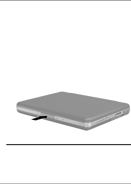
Display
Component |
Description |
|
|
Display release latch |
Opens the notebook. |
|
|
Hardware Guide |
1–1 |
Hardware Components
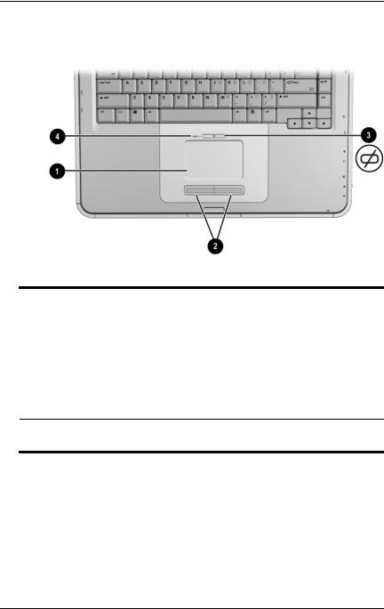
TouchPad
Component |
Description |
|
|
|
|
1 |
TouchPad* |
Moves the pointer and selects or |
|
|
activates items on the screen. |
|
|
|
2 |
Left and right TouchPad |
Function like the left and right buttons |
|
buttons |
on an external mouse. |
|
|
|
3 |
TouchPad on/off button |
Turns TouchPad on or off. |
|
|
|
4 |
TouchPad light |
On: TouchPad is enabled. |
*For information about TouchPad settings, see Chapter 2, “TouchPad and Keyboard.”
1–2 |
Hardware Guide |
Hardware Components
Top Components
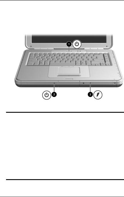
Power Lights
Component |
Description |
|
|
|
|
1 |
Power button light |
On: Notebook is turned on. |
|
|
Blinking: Notebook is in Standby. |
|
|
Off: Notebook is off or in Hibernation. |
|
|
|
2 |
Power/Standby light |
On: Notebook is turned on. |
|
|
Blinking: Notebook is in Standby. |
|
|
Off: Notebook is off or in Hibernation. |
|
|
|
3 |
Battery light |
On: Battery pack is charging. |
|
|
Blinking: Battery pack has reached a |
|
|
low-battery condition. |
Off: AC power is applied, with battery pack either fully charged or not installed, or no AC power is applied.
Hardware Guide |
1–3 |
Hardware Components
Keyboard and Drive Lights
Component |
Description |
|
|
|
|
1 |
Caps lock light |
On: Caps lock is on. |
|
|
|
2 |
Num lock light |
On: Num lock or the internal |
|
|
keypad is on.* |
|
|
|
3 |
IDE (Integrated Drive |
On: The internal hard drive or the |
|
Electronics) light; also |
optical drive bay is being accessed. |
|
referred to as hard |
|
|
drive/optical drive activity |
|
|
light |
|
|
|
|
4 |
Optical disk drive light |
On: The optical drive bay is being |
|
|
accessed. |
|
|
|
5 |
5-in-1 Memory Reader light |
On: Memory Reader is accessing an |
|
(select models) |
optional digital media card. |
*For information about using num lock, the internal keypad, or an external keypad, see Chapter 2, “TouchPad and Keyboard.”
1–4 |
Hardware Guide |

Hardware Components
Power and Volume Controls
Component |
Description |
|
|
|
|
1 |
Power button* |
When the notebook is: |
|
|
■ Off, press the button to turn on the notebook. |
|
|
■ On, briefly press the button to initiate Hibernation. |
|
|
■ In Standby, briefly press the button to resume |
|
|
from Standby. |
|
|
■ In Hibernation, briefly press the button to resume |
|
|
from Hibernation. |
|
|
If the system has stopped responding and |
|
|
Microsoft® Windows® shutdown |
|
|
procedures cannot be used, press and hold |
|
|
the button for at least 4 seconds to turn off |
|
|
the notebook. |
|
|
|
2 |
Mute button |
On: Audio is muted. |
|
|
|
3 |
Volume |
Decrease and increase the system volume: |
|
buttons (2) |
■ To decrease volume, use the left button. |
|
|
|
■ To increase volume, use the right button.
*This table describes default settings. For information about changing the function of the power button, refer to the “Power” chapter in the Software Guide on this CD.
Hardware Guide |
1–5 |
Hardware Components
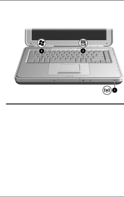
Wireless On/Off Button and
Application Keys
Component |
Description |
|
|
|
|
1 |
Wireless On/Off button |
Enables wireless functionality, but |
|
|
does not create a wireless connection. |
|
|
To set up and complete a |
|
|
wireless connection, |
|
|
additional hardware and |
|
|
software might be required. |
|
|
|
2 |
Windows logo key |
Displays Windows Start menu. |
|
|
|
3 |
Windows Applications key |
Displays shortcut menu for any |
|
|
highlighted items. |
|
|
|
1–6 |
Hardware Guide |

Hardware Components
Function and Keypad Keys
Component |
Description |
|
|
|
|
1 |
Fn key |
Combines with the function keys to |
|
|
perform additional system and |
|
|
application tasks. For example, |
|
|
pressing Fn+F8 increases screen |
|
|
brightness. |
|
|
|
2 |
Function keys (11)* |
Perform system and application tasks. |
|
|
When combined with the Fn key, |
|
|
function keys F1 through F12 perform |
|
|
additional tasks as hotkeys. (The |
|
|
F2 function key is not used.) |
|
|
|
3 |
Keypad keys (15) |
Can be used like the keys on an |
|
|
external numeric keypad. |
*For more information, refer to the “Hotkey Quick Reference” section in Chapter 2, “TouchPad and Keyboard.”
Hardware Guide |
1–7 |
Hardware Components
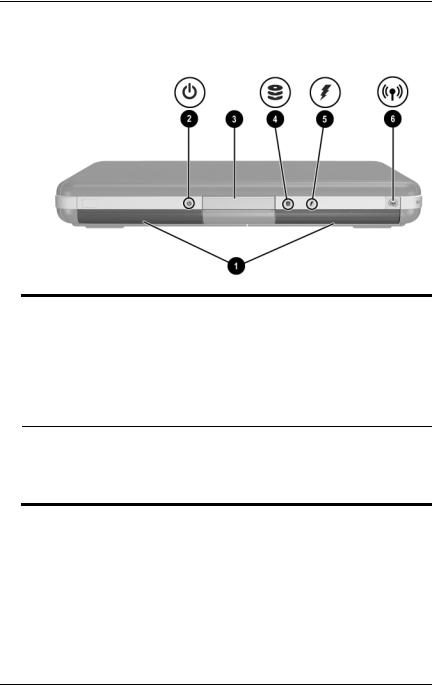
Front Components
Component |
Description |
|
|
|
|
1 |
Stereo speakers (2) |
Produce stereo sound. |
|
|
|
2 |
Power/Standby light |
On: Notebook is turned on. |
|
|
Blinking: Notebook is in Standby. |
|
|
Off: Notebook is off or in Hibernation. |
|
|
|
3 |
Display release latch |
Opens the notebook. |
4IDE (Integrated Drive Electronics) light; also referred to as hard drive/optical drive activity light
On: The internal hard drive or optical drive bay is being accessed.
(continued)
1–8 |
Hardware Guide |

|
|
|
Hardware Components |
|
|
|
|
5 |
Battery light |
On: Battery pack is charging. |
|
|
|
|
Blinking: Battery pack has reached a |
|
|
|
low-battery condition. |
|
|
|
Off: AC power is applied, with battery |
|
|
|
pack either fully charged or not |
|
|
|
installed, or no AC power is applied. |
|
|
|
|
6 |
Wireless On/Off button |
Enables wireless functionality, but |
|
|
|
|
does not create a wireless connection. |
To set up and complete a wireless connection, additional hardware and software might be required.
Hardware Guide |
1–9 |

Hardware Components
Rear Components
Component |
Description |
|
|
|
|
1 |
Power connector |
Connects an AC adapter. |
|
|
|
2 |
Exhaust vent |
Allows airflow to cool internal |
|
|
components. Additional vents are |
|
|
on the bottom of the notebook. |
|
|
Ä To prevent overheating, do |
|
|
not obstruct the vent. Do not |
|
|
allow a hard surface, such as |
|
|
an adjoining printer, or a soft |
|
|
surface, such as bedding or |
|
|
clothing, to block airflow. |
|
|
|
3 |
External monitor connector |
Connects an optional external monitor |
|
|
or overhead projector. |
|
|
|
4 |
Parallel connector |
Connects an optional parallel device, |
|
|
such as a printer. |
|
|
|
5 |
RJ-11 jack (select models) |
Connects the modem cable. |
|
|
(select models) |
|
|
|
1–10 |
Hardware Guide |
Hardware Components
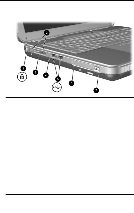
Left-Side Components
1
Component |
Description |
|
|
|
|
1 |
Security cable slot |
Attaches an optional security cable to |
|
|
the notebook. |
|
|
The purpose of security |
|
|
solutions is to act as a |
|
|
deterrent. These solutions do |
|
|
not prevent the product from |
|
|
being mishandled or stolen. |
|
|
|
2 |
5-in-1 Memory Reader and |
Supports 5 optional digital media |
|
light (select models) |
formats: SD Memory Card, |
|
|
MultiMediaCard, SmartMedia, |
|
|
Memory Stick, and Memory Stick Pro. |
|
|
Light On: Slot is accessing digital |
|
|
media. |
|
|
|
3 |
PC Card slot (1 or 2 slots, |
Supports an optional Type I or Type II |
|
select models) |
32-bit (CardBus) or 16-bit PC Card. |
|
|
|
4 |
PC Card eject button (1 or |
Ejects an optional PC Card from the |
|
2 buttons, select models) |
PC Card slot. |
(continued)
Hardware Guide |
1–11 |

Hardware Components
5 |
USB connectors (2) |
Connect optional USB devices, such as |
|
|
printers. |
|
|
|
6 |
Three drive configurations: |
Digital Bay: Supports optional |
|
optional Digital Bay, optional |
pocket-sized Digital Drive. |
|
diskette drive, no drive |
Diskette drive: Supports standard |
|
|
1.4-MB diskette. |
|
|
No drive: No drive bay is installed. |
7One of 4 optical drive bay configurations
■CD-ROM drive
■DVD-ROM drive
■DVD/CD-RW combo drive—Can write to recordable CDs, but cannot write to recordable DVDs. (Type of drive varies by model.)
■DVD+RW/R and CD-RW combo drive—Can write to both recordable CDs and DVDs.
1–12 |
Hardware Guide |

Hardware Components
Right-Side Components
Component |
Description |
|
|
|
|
1 |
Wireless on/off light |
On: Wireless functionality is enabled, but |
|
|
wireless connection might not be |
|
|
configured. |
|
|
Off: No wireless device is active. |
|
|
|
2 |
Volume buttons (3) and |
Decrease, mute, and increase the system |
|
audio mute light |
volume: |
|
|
■ To decrease volume, use left button. |
|
|
■ To increase volume, use middle |
|
|
button. |
|
|
■ To mute or restore volume, use right |
|
|
button. |
|
|
■ Light on: Audio is muted. |
|
|
|
3 |
Audio-out headphone jack |
Connects an optional headphone, a |
|
|
headset, or powered stereo speakers. |
|
|
Also connects the audio function of an |
|
|
audio/video device, such as a television |
|
|
or VCR. |
(continued)
Hardware Guide |
1–13 |
Hardware Components
4 |
Audio-in microphone jack |
Connects an optional external |
|
|
microphone. |
|
|
|
5 |
USB connector |
Connects an optional USB device, such |
|
|
as a printer. |
|
|
|
6 |
1394 connector |
Connects an optional IEEE 1394 device, |
|
(select models) |
such as a camcorder. |
|
|
|
7 |
Infrared port |
Provides wireless communication |
|
(select models) |
between the notebook and an optional |
|
|
IrDA-compliant device. |
|
|
|
8 |
Expansion port |
Connects an optional HP Notebook |
|
|
Expansion Base. |
|
|
|
9 |
RJ-45 network jack |
Connects an optional network cable. |
|
|
|
- |
S-Video-out jack |
Connects an optional S-Video device, |
|
|
such as a television, VCR, camcorder, |
|
|
overhead projector, or video capture card. |
|
|
|
1–14 |
Hardware Guide |

Hardware Components
Bottom Components
Component |
Description |
|
|
|
|
1 |
Battery release latch |
Releases the battery pack from the |
|
|
battery bay. |
|
|
|
2 |
Battery bay |
Holds the battery pack. (Battery shipment |
|
|
and type vary by model.) |
|
|
|
3 |
Exhaust vents |
Allow airflow to cool internal components. |
|
|
Ä To prevent overheating, do not |
|
|
obstruct the vent. Do not allow a |
|
|
hard surface, such as an |
|
|
adjoining printer, or a soft |
|
|
surface, such as bedding or |
|
|
clothing, to block airflow. |
|
|
|
4 |
Hard drive bay |
Holds the primary hard drive. |
|
|
|
5 |
Memory compartment |
Contains 2 memory slots, one of which is |
|
|
accessible for an optional 128-MB, |
|
|
256-MB, 512-MB, or 1024-MB memory |
|
|
module upgrade. As shipped, the memory |
|
|
slot might be filled with a replaceable |
|
|
memory module, or it might be vacant, |
|
|
depending on the notebook model. |
|
|
|
Hardware Guide |
1–15 |

Hardware Components
Labels
The labels affixed to the bottom of the notebook and to the inside of the battery compartment provide information you might need when troubleshooting system problems or traveling abroad with the notebook.
■The Service Tag label affixed to the bottom of the notebook contains the product name, product number (P/N), and serial number (S/N). You will need the notebook serial number and product number if you call customer support.
■The Microsoft Certificate of Authenticity label affixed to the bottom of the notebook contains the Product Key. You might need this number to update or troubleshoot problems with the operating system.
■The System label affixed to the inside of the battery compartment provides regulatory information about the notebook.
■The Product identification label affixed to the inside of the battery compartment contains the serial number (S/N) of the notebook and a code describing the original configuration of the notebook.
■The Modem approval label affixed to an optional internal modem provides regulatory information.
■The wireless certification labels affixed to the inside of the battery compartment are specific to various types of optional wireless devices. These labels provide regulatory information and list the countries in which the optional wireless devices have been approved for use. You might need the wireless device information in order to use the wireless device while traveling.
1–16 |
Hardware Guide |

Hardware Components
Additional Standard Components
The components included with the notebook vary by geographic region and by model. The following illustrations and tables identify the standard external components included with most notebook models.
Documentation Library CD
Your notebook Documentation Library CD includes the following guides:
■Hardware Guide (the document you are viewing)
■Software Guide
■Maintenance, Shipping and Travel guide
■Regulatory and Safety Notices
■Safety & Comfort Guide
■Troubleshooting guide
■Modem and Networking guide
For information about using the Documentation Library CD, refer to the printed Startup Guide included with the notebook.
Hardware Guide |
1–17 |
Hardware Components
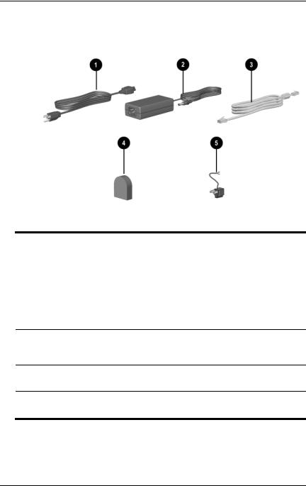
Cords, Cables and Adapters
Component |
Description |
|
|
|
|
1 |
Power cord* |
Connects the AC adapter to an |
|
|
AC electrical outlet. |
|
|
|
2 |
AC adapter** |
Converts AC power to DC power. |
|
|
|
3 |
Modem cables |
Connects the modem to an |
|
(select models)* |
RJ-11 telephone jack or to a |
|
|
country-specific modem adapter. |
4Country-specific modem adapter (included by region as required)
Adapts the modem cable to a non-RJ-11 telephone jack.
5 Japan-specific outlet adapter |
Connects the AC adapter to a 2-prong |
(Japan only) |
electrical outlet. |
*Power cords and modem cables vary in appearance by region. **AC adapters vary by region.
1–18 |
Hardware Guide |
2
TouchPad and Keyboard
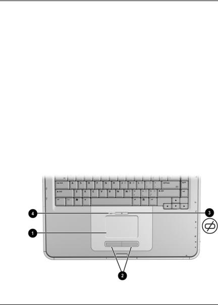
Using the TouchPad
The TouchPad duplicates the functions of an optional external mouse.
■To move the pointer, slide your finger across the TouchPad surface 1 in the direction you want to move the cursor.
If the cursor continues to move after you take your finger off the TouchPad, wait a few seconds for the cursor to stop moving.
■Use the left and right TouchPad buttons 2 as you would the left and right buttons on an external mouse.
■Use the TouchPad on/off button 3 to turn off the Touchpad. This also turns off the TouchPad light 4.
Identifying TouchPad components
Hardware Guide |
2–1 |

TouchPad and Keyboard
Setting TouchPad Preferences
The TouchPad is supported by the mouse software in the operating system. To access the Mouse Properties window, select Start > Control Panel > Printers and Other Hardware > Mouse.
Among the settings you can select are:
■TouchPad tapping, which enables you to tap the TouchPad once or twice to select an object.
■Inertial Movement, which enables you to continue to scroll even though your finger has reached the edge of the TouchPad.
■Typing, which prevents inadvertent tapping when typing on the keyboard.
Other features, such as sensitivity, virtual scrolling, mouse trails, and mouse speed preferences, are available in the Mouse Properties window.
2–2 |
Hardware Guide |

TouchPad and Keyboard
Using the Hotkeys
In this guide, the function keys are capitalized (Fn, F5). The function keys on your keyboard might be lowercase (fn, f5).
Hotkeys are preset combinations of the Fn key 1 and one of the function keys 2. Excluding function key F2, the icons on F1 through F12 represent the hotkey functions available on your notebook. The F2 function key is not used.
Identifying hotkeys
Hardware Guide |
2–3 |

TouchPad and Keyboard
Hotkey Quick Reference
The following table identifies the hotkey functions set at the factory.
Default Function |
Hotkey |
|
|
Open Help and Support Center. |
Fn+F1 |
|
|
Not used. |
Fn+F2 |
|
|
Open Microsoft Internet Explorer. |
Fn+F3 |
|
|
Switch display image. |
Fn+F4 |
|
|
Initiate Standby. |
Fn+F5 |
|
|
Initiate QuickLock. |
Fn+F6 |
|
|
Decrease screen brightness. |
Fn+F7 |
|
|
Increase screen brightness. |
Fn+F8 |
|
|
Play, pause, or resume an audio CD or DVD. |
Fn+F9 |
|
|
Stop an audio CD or DVD. |
Fn+F10 |
|
|
Play the previous track or chapter of an audio |
Fn+F11 |
CD or DVD. |
|
|
|
Play the next track of an audio CD or DVD. |
Fn+F12 |
|
|
2–4 |
Hardware Guide |

TouchPad and Keyboard
Hotkey Procedures
To use a hotkey command on the notebook keyboard:
■Briefly press the Fn key, and then briefly press the second key of the command.
-or-
■Press and hold down the Fn key, briefly press the second key, and then release both keys simultaneously.
Hotkey Commands
Open Help and Support Center (Fn+F1)
The Help and Support Center provides a comprehensive online resource tool for contacting a Compaq support specialist, for downloading the latest software driver updates and product information, and for learning more about using and maintaining your notebook.
Press the Fn+F1 hotkey to open the Help and Support Center window.
Open Internet Explorer (Fn+F3)
Press the Fn+F3 hotkey to open Microsoft Internet Explorer.
Switch Display Image (Fn+F4)
The Fn+F4 hotkey switches the image among display devices connected to the notebook. For example, if an external monitor is connected to the notebook, pressing Fn+F4 multiple times switches the image among the notebook display, the external monitor display, and a simultaneous display on both the notebook and the external monitor.
Hardware Guide |
2–5 |
 Loading...