


 Loading...
HP Compaq Evo n800c, Compaq Presario 2800AU, Compaq Presario 2800CA, Compaq Presario 2800SC, Compaq Presario 2800TC Hardware manual
...b
Hardware Guide
Compaq Notebook Series
Document Part Number: 265656-001
June 2002
This guide explains how to identify and use notebook hardware features, including connectors for external devices. It also includes power and environmental specifications, which may be helpful when traveling with the notebook.
© 2002 Compaq Information Technologies Group, L.P.
Compaq, the Compaq logo, Evo, and Presario are trademarks of Compaq Information Technologies Group, L.P. in the U.S. and/or other countries.
Microsoft and Windows are trademarks of Microsoft Corporation in the U.S. and/or other countries.
All other product names mentioned herein may be trademarks of their respective companies.
Compaq shall not be liable for technical or editorial errors or omissions contained herein. The information is provided “as is” without warranty of any kind and is subject to change without notice. The warranties for Compaq products are set forth in the express limited warranty statements accompanying such products. Nothing herein should be construed as constituting an additional warranty.
Hardware Guide
First Edition June 2002
Reference Number: N800/2800
Document Part Number: 265656-001

Contents
1 Identifying External Hardware
Display Components . . . . . . . . . . . . . . . . . . . . . . . . . . . . 1–1
Pointing Device Components. . . . . . . . . . . . . . . . . . . . . . 1–2
TouchPad Models . . . . . . . . . . . . . . . . . . . . . . . . . . . 1–2
Dual Device Models . . . . . . . . . . . . . . . . . . . . . . . . . 1–3
Top Components . . . . . . . . . . . . . . . . . . . . . . . . . . . . . . . 1–4
Power Lights . . . . . . . . . . . . . . . . . . . . . . . . . . . . . . . 1–4
Keyboard and Drive Lights . . . . . . . . . . . . . . . . . . . . 1–5
Power and Volume Controls . . . . . . . . . . . . . . . . . . . 1–6
Easy Access Buttons and Keyboard Keys. . . . . . . . . 1–7
Function and Keypad Keys . . . . . . . . . . . . . . . . . . . . 1–8
Front Panel Components . . . . . . . . . . . . . . . . . . . . . . . . . 1–9
Rear Panel Components . . . . . . . . . . . . . . . . . . . . . . . . . 1–10
Connectors . . . . . . . . . . . . . . . . . . . . . . . . . . . . . . . . 1–10
Vent, Port and Jacks . . . . . . . . . . . . . . . . . . . . . . . . 1–11
Left Side Components . . . . . . . . . . . . . . . . . . . . . . . . . . 1–12
Right Side Components . . . . . . . . . . . . . . . . . . . . . . . . . 1–13
Underside Components . . . . . . . . . . . . . . . . . . . . . . . . . 1–14
Memory and Mini PCI Compartments . . . . . . . . . . 1–14
Bay Components . . . . . . . . . . . . . . . . . . . . . . . . . . . 1–15
Vent and Docking Components. . . . . . . . . . . . . . . . 1–16
Labels. . . . . . . . . . . . . . . . . . . . . . . . . . . . . . . . . . . . 1–17
Additional Standard Components . . . . . . . . . . . . . . . . . 1–18
Documentation and Restore CDs . . . . . . . . . . . . . . 1–18
Cord and Cables. . . . . . . . . . . . . . . . . . . . . . . . . . . . 1–19
Adapters and Accessories . . . . . . . . . . . . . . . . . . . . 1–20
Hardware Guide |
iii |

Contents
2 Pointing Devices and Keyboard
Pointing Devices . . . . . . . . . . . . . . . . . . . . . . . . . . . . . . . 2–1
Pointing Devices on TouchPad Models Only . . . . . . 2–1
Pointing Devices on Dual Device Models Only . . . . 2–2
Setting Pointing Device Preferences . . . . . . . . . . . . . 2–4
Hotkeys . . . . . . . . . . . . . . . . . . . . . . . . . . . . . . . . . . . . . . 2–5
Identifying Hotkeys . . . . . . . . . . . . . . . . . . . . . . . . . . 2–5
Hotkey Quick Reference . . . . . . . . . . . . . . . . . . . . . . 2–6
Hotkey Procedures. . . . . . . . . . . . . . . . . . . . . . . . . . . 2–6
Hotkey Commands . . . . . . . . . . . . . . . . . . . . . . . . . . 2–7
Easy Access Buttons . . . . . . . . . . . . . . . . . . . . . . . . . . . 2–11
Using the Default Settings. . . . . . . . . . . . . . . . . . . . 2–11
Using Custom Assignments and Schemes. . . . . . . . 2–13
Keypads . . . . . . . . . . . . . . . . . . . . . . . . . . . . . . . . . . . . . 2–14
Using the Internal Keypad. . . . . . . . . . . . . . . . . . . . 2–14
Using an External Keypad. . . . . . . . . . . . . . . . . . . . 2–16
3 Battery Packs
Running the Notebook on Battery Power . . . . . . . . . . . . 3–1 Identifying Battery Packs. . . . . . . . . . . . . . . . . . . . . . . . . 3–2 Inserting or Removing a Primary Battery Pack . . . . . . . . 3–3 Inserting or Removing a MultiBay Battery Pack. . . . . . . 3–4 Charging a Battery Pack. . . . . . . . . . . . . . . . . . . . . . . . . . 3–5
Charging a New Battery Pack . . . . . . . . . . . . . . . . . . 3–6 Charging an In-Use Battery Pack . . . . . . . . . . . . . . . 3–6 Charging a Primary and a MultiBay Battery Pack . . 3–6 Monitoring the Charge in a Battery Pack. . . . . . . . . . . . . 3–7 Obtaining Accurate Charge Information . . . . . . . . . . 3–7 Displaying Charge Information on the Screen . . . . . 3–7 Displaying Charge Information on a Battery Pack . . 3–9 Managing Low-Battery Conditions . . . . . . . . . . . . . . . . 3–10 Identifying Low-Battery Conditions . . . . . . . . . . . . 3–10 Resolving Low-Battery Conditions . . . . . . . . . . . . . . . . 3–11
iv |
Hardware Guide |

Contents
Calibrating a Battery Pack . . . . . . . . . . . . . . . . . . . . . . . 3–12 When to Calibrate . . . . . . . . . . . . . . . . . . . . . . . . . . 3–12 How to Calibrate . . . . . . . . . . . . . . . . . . . . . . . . . . . 3–12 Battery Conservation Procedures and Settings . . . . . . . 3–15 Conserving Power as You Work . . . . . . . . . . . . . . . 3–15 Selecting Power Conservation Settings. . . . . . . . . . 3–16 Storing a Battery Pack . . . . . . . . . . . . . . . . . . . . . . . . . . 3–17 Disposing of a Used Battery Pack . . . . . . . . . . . . . . . . . 3–18 Finding More Power Information . . . . . . . . . . . . . . . . . 3–18
4 Drives
Adding a Drive to the System . . . . . . . . . . . . . . . . . . . . . 4–1 Understanding Drive Terms. . . . . . . . . . . . . . . . . . . . . . . 4–2 Terms for Types of Drives. . . . . . . . . . . . . . . . . . . . . 4–2 Terms for Drive Media . . . . . . . . . . . . . . . . . . . . . . . 4–2 Caring for Drives . . . . . . . . . . . . . . . . . . . . . . . . . . . . . . . 4–3 Using the IDE Drive Light. . . . . . . . . . . . . . . . . . . . . . . . 4–4 Removing and Inserting a MultiBay Drive . . . . . . . . . . . 4–5 Using a MultiBay Hard Drive Adapter . . . . . . . . . . . 4–5 Removing a Drive from the MultiBay. . . . . . . . . . . . 4–8 Inserting a Drive into the MultiBay. . . . . . . . . . . . . 4–10 Inserting and Removing Drive Media . . . . . . . . . . . . . . 4–11 Inserting a CD or DVD . . . . . . . . . . . . . . . . . . . . . . 4–11 Removing a CD or DVD (With Power) . . . . . . . . . 4–12 Removing a CD or DVD (Without Power) . . . . . . . 4–13 Inserting a Diskette or Disk . . . . . . . . . . . . . . . . . . . 4–14 Removing a Diskette or Disk. . . . . . . . . . . . . . . . . . 4–14 Using Drive Media. . . . . . . . . . . . . . . . . . . . . . . . . . . . . 4–15 Avoiding Standby and Hibernation . . . . . . . . . . . . . 4–15 Displaying Media Contents . . . . . . . . . . . . . . . . . . . 4–15 Caring for Drive Media . . . . . . . . . . . . . . . . . . . . . . 4–17 Finding More Drive Software Information . . . . . . . . . . 4–18
Hardware Guide |
v |

Contents
5 Audio and Video
Adjusting Volume . . . . . . . . . . . . . . . . . . . . . . . . . . . . . . 5–1 Using the Volume Buttons . . . . . . . . . . . . . . . . . . . . 5–1 Using the Volume Control Icon. . . . . . . . . . . . . . . . . 5–2 Using the Internal Speakers . . . . . . . . . . . . . . . . . . . . . . . 5–3 Using the Internal Microphone . . . . . . . . . . . . . . . . . . . . 5–4 Connecting an Audio Device . . . . . . . . . . . . . . . . . . . . . . 5–5 Identifying Audio Jacks. . . . . . . . . . . . . . . . . . . . . . . 5–5 Using the Microphone Jack . . . . . . . . . . . . . . . . . . . . 5–6 Using the Audio-Out Jack . . . . . . . . . . . . . . . . . . . . . 5–6 Connecting a Video Device . . . . . . . . . . . . . . . . . . . . . . . 5–7 S-Video and Composite-Video Connections. . . . . . . 5–7 Connecting an S-Video Device . . . . . . . . . . . . . . . . . 5–8 Turning a Video Device On and Off . . . . . . . . . . . . . 5–9 Changing the Color Television Format . . . . . . . . . . 5–10 Finding CD and DVD Software Information. . . . . . . . . 5–11
6 External Device Connections
Connecting a Standard Device . . . . . . . . . . . . . . . . . . . . . 6–1 Connecting a USB Device . . . . . . . . . . . . . . . . . . . . . . . . 6–2 Using a USB Device . . . . . . . . . . . . . . . . . . . . . . . . . 6–3 Enabling USB Legacy Support . . . . . . . . . . . . . . . . . 6–3 Linking to an Infrared Device . . . . . . . . . . . . . . . . . . . . . 6–4 Setting Up an Infrared Transmission. . . . . . . . . . . . . 6–5 Avoiding Standby While Using Infrared. . . . . . . . . . 6–5 Connecting an Optional Cable Lock . . . . . . . . . . . . . . . . 6–6 Finding Communication and Security Information . . . . . 6–6
7 Hardware Upgrades
Obtaining Upgrades . . . . . . . . . . . . . . . . . . . . . . . . . . . . . 7–1
Using PC Cards . . . . . . . . . . . . . . . . . . . . . . . . . . . . . . . . 7–1
Selecting a PC Card. . . . . . . . . . . . . . . . . . . . . . . . . . 7–1
Configuring a PC Card . . . . . . . . . . . . . . . . . . . . . . . 7–2
Inserting a PC Card . . . . . . . . . . . . . . . . . . . . . . . . . . 7–2
Stopping and Removing a PC Card. . . . . . . . . . . . . . 7–3
vi |
Hardware Guide |

Contents
Increasing Memory . . . . . . . . . . . . . . . . . . . . . . . . . . . . . 7–4 Displaying Memory Information. . . . . . . . . . . . . . . . 7–4 Removing or Inserting a Memory Board. . . . . . . . . . 7–5 Replacing the Primary Hard Drive. . . . . . . . . . . . . . . . . 7–10 Finding Mini PCI and MultiPort Information . . . . . . . . 7–12
8 Specifications
Regulatory Agency Series Numbers . . . . . . . . . . . . . . . . 8–1
Notebook Dimensions . . . . . . . . . . . . . . . . . . . . . . . . . . . 8–2
Operating Environment . . . . . . . . . . . . . . . . . . . . . . . . . . 8–2
Rated Input Power . . . . . . . . . . . . . . . . . . . . . . . . . . . . . . 8–3
Modem Specifications . . . . . . . . . . . . . . . . . . . . . . . . . . . 8–3
Finding More Environmental Information. . . . . . . . . . . . 8–4
Index
Hardware Guide |
vii |
1
Identifying External Hardware
Display Components
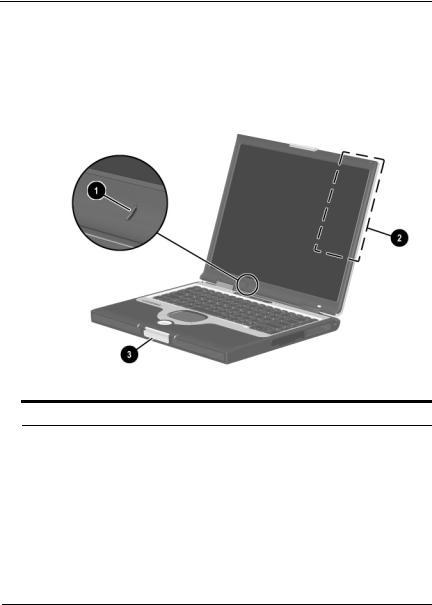
Display Components
1 |
Microphone |
Inputs single-channel sound. |
|
|
|
2 |
MultiPort |
Supports an optional USB-enabled |
|
|
wireless device such as a Bluetooth |
|
|
MultiPort, 802.11b Wireless LAN |
|
|
MultiPort, and future wireless |
|
|
technologies. |
|
|
|
3 |
Display release latch |
Opens the notebook. |
|
|
|
Hardware Guide |
1–1 |
Identifying External Hardware
Pointing Device Components
TouchPad Models
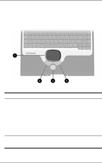
Pointing Device Components: TouchPad Models
1 |
TouchPad |
Moves the cursor. Can be set to |
|
|
perform additional mouse functions |
|
|
such as scroll, select, and |
|
|
double-click.* |
|
|
|
2 |
Left and right TouchPad |
Function like the left and right buttons |
|
buttons |
on an external mouse. |
|
|
|
3 |
Scroll button |
Scrolls up, down, left, or right through |
|
|
most application and Internet browser |
|
|
windows. |
*For information about modifying pointing device functions, refer in this guide to the “Pointing Devices and Keyboard” section, “Setting Pointing Device Preferences.”
1–2 |
Hardware Guide |
Identifying External Hardware
Dual Device Models
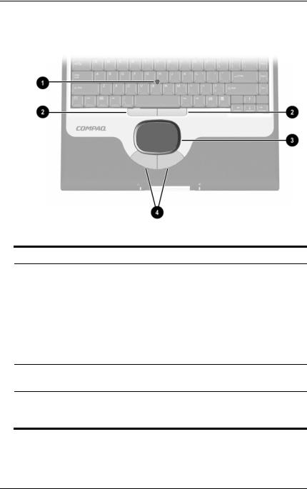
Pointing Device Components: Dual Device Models
1 |
Pointing stick |
Moves the cursor and selects and |
|
|
activates items on the screen. |
|
|
|
2 |
Left and right pointing-stick |
Function like the left and right buttons |
|
buttons |
on an external mouse. |
|
|
|
3 |
TouchPad |
Moves the pointer. Can be set to |
|
|
perform additional mouse functions |
such as scroll, select, and double-click.*
4Left and right TouchPad buttons
Function like the left and right buttons on an external mouse.
*For information about modifying pointing device functions, refer in this guide to the “Pointing Devices and Keyboard” section, “Setting Pointing Device Preferences.”
Hardware Guide |
1–3 |
Identifying External Hardware
Top Components
Power Lights
Top Components: Power Lights
1 |
AC Adapter light |
On: AC power is being supplied |
|
|
through the AC Adapter. |
|
|
|
2 |
Power/standby light |
On: Power is turned on. |
|
|
Blinking: Notebook is in Standby. |
|
|
|
3 |
Battery light |
On: A battery pack is charging. |
|
|
Blinking: A battery pack that is the |
|
|
only available power source has |
|
|
reached a low-battery condition. |
|
|
|
1–4 |
Hardware Guide |

Identifying External Hardware
Keyboard and Drive Lights
Top Components: Keyboard and Drive Lights
1 |
Num lock light |
On: Num lock is on or the internal |
|
|
keypad is on.* |
|
|
|
2 |
Caps lock light |
On: Caps lock is on. |
|
|
|
3 |
IDE (Integrated Drive |
On: One of the following drives is |
|
Electronics) drive light |
being accessed: |
■ Hard drive in the hard drive bay.
■ Optional hard drive, Zip drive, SuperDisk drive, or any type of CD or DVD drive in the MultiBay.
*For more information about using num lock, the internal keypad, or an external keypad, refer in this guide to the “Pointing Devices and Keyboard” section, “Keypads.”
Hardware Guide |
1–5 |
Identifying External Hardware
Power and Volume Controls
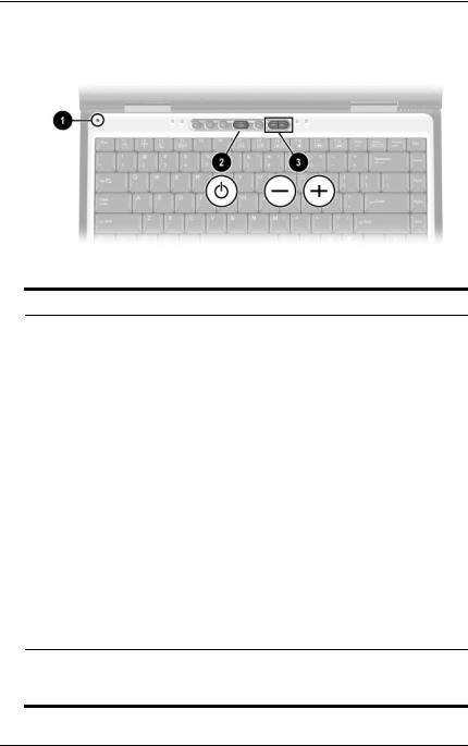
Top Components: Power and Volume Controls
1 |
Display switch* |
Turns off the notebook display if the |
|
|
notebook is closed while it is on. |
|
|
|
2 |
Power button* |
When the notebook is: |
|
|
■ Off, briefly press to turn on the |
|
|
notebook. |
|
|
■ On, briefly press to initiate |
|
|
Hibernation. |
|
|
■ In Standby, briefly press to exit |
|
|
Standby. |
|
|
■ In Hibernation, briefly press to exit |
|
|
Hibernation. |
|
|
If the system has stopped responding |
|
|
and Windows shut down procedures |
|
|
cannot be used, press and hold for 4 |
|
|
seconds to turn off the notebook. |
|
|
|
3 |
Volume buttons (2) |
Adjust, mute, or restore system volume. |
|
|
To mute or restore volume, press both |
|
|
volume buttons at the same time. |
*This table describes default settings. For information about changing the function of the power button, display switch, or Fn+F3 hotkeys, refer on this CD to the Software Guide, “Power” section.
1–6 |
Hardware Guide |
Identifying External Hardware
Easy Access Buttons and Keyboard Keys
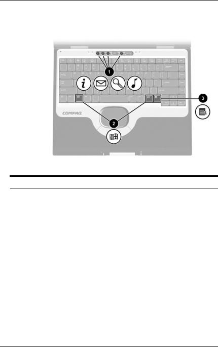
Top Components: Easy Access Buttons and Keyboard Keys
1Easy Access Buttons (4) Provide quick access to Internet or
|
|
network destinations, or to software |
|
|
applications or data files on a drive. |
|
|
The icon on each button represents |
|
|
the default destination. Buttons can |
|
|
be programmed to different |
|
|
destinations. |
|
|
|
2 |
Microsoft logo keys (2) |
Display Windows Start menu. |
|
|
|
3 |
Applications key |
Displays shortcut menu for item |
|
|
beneath the pointer. |
|
|
|
Hardware Guide |
1–7 |
Identifying External Hardware
Function and Keypad Keys
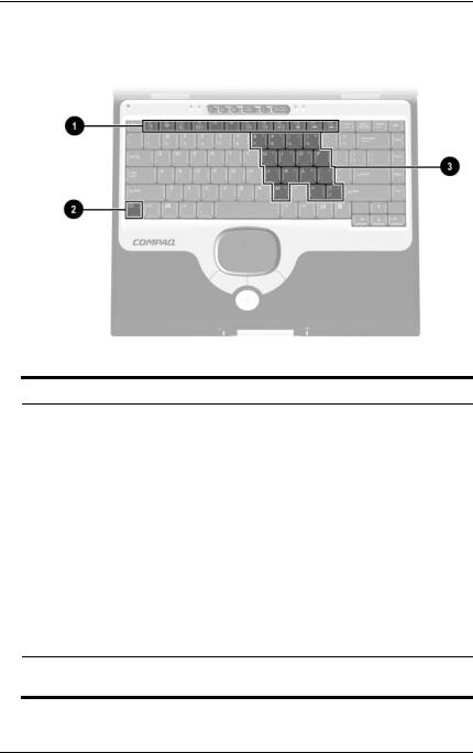
Top Components: Function and Keypad Keys
1 |
Function keys (12) |
Perform system and application |
|
|
tasks. For example, in Windows and |
|
|
many applications, pressing F1 opens |
|
|
a Help file. When combined with the |
|
|
Fn key, the function keys F2 through |
|
|
F4 and F7 through F12 perform |
|
|
additional tasks as hotkeys.* |
|
|
|
2 |
Fn key |
Combines with other keys to perform |
|
|
system tasks. For example, pressing |
|
|
the Fn+F7 hotkeys decreases screen |
|
|
brightness and pressing the Fn+F8 |
|
|
hotkeys increases screen brightness. |
|
|
|
3 |
Keypad keys (15)* |
Can be used like the keys on an |
|
|
external numeric keypad. |
*For more information about using hotkeys or keypad keys, refer in this guide to the “Pointing Devices and Keyboard” section.
1–8 |
Hardware Guide |
Identifying External Hardware
Front Panel Components
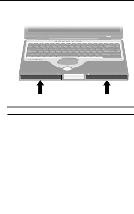
Front Panel Components
Stereo speakers (2) |
Produce stereo sound. |
|
|
Hardware Guide |
1–9 |
Identifying External Hardware
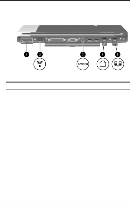
Rear Panel Components
Connectors
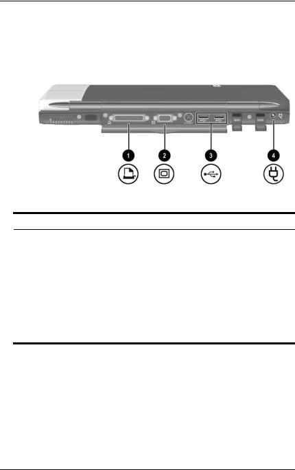
Rear Panel Components: Connectors
1 |
Parallel connector |
Connects an optional parallel device |
|
|
such as a printer. |
|
|
|
2 |
External monitor connector |
Connects an optional external |
|
|
monitor or overhead projector. |
|
|
|
3 |
USB connectors (2) |
Connect optional USB devices. |
|
|
|
4 |
DC power connector |
Connects an AC Adapter or an |
|
|
optional DC Cable, Aircraft Power |
Adapter, or Automobile Power
Adapter/Charger.
1–10 |
Hardware Guide |
Identifying External Hardware
Vent, Port and Jacks
Rear Panel Components: Vent, Port and Jacks
1 |
Vent (1 of 3) |
Allows airflow to cool internal |
|
|
components. |
|
|
ÄTo prevent overheating, do |
|
|
not obstruct the vent. Do not |
|
|
allow a hard surface, such as |
|
|
an adjoining optional printer, |
|
|
or a fabric, such as bedding |
|
|
or clothing, to block airflow. |
|
|
|
2 |
Infrared port |
Provides wireless communication |
|
|
between the notebook and an |
|
|
optional IrDA-compliant device. |
|
|
|
3 |
S-video-out jack |
Connects an optional S-video device |
|
|
such as a television, VCR, or |
|
|
camcorder. |
|
|
|
4 |
RJ-11 telephone jack |
Connects the modem cable. |
|
|
|
5 |
RJ-45 network jack |
Connects a network cable. A network |
|
|
cable is included with select models. |
|
|
|
Hardware Guide |
1–11 |
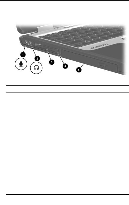
Identifying External Hardware
Left Side Components
Left Side Components
1 |
Microphone jack |
Connects an optional single-sound channel |
|
|
microphone. |
|
|
|
2 |
Audio-out jack |
Connects optional headphones, a headset, |
|
|
or powered stereo speakers. Also connects |
|
|
the audio function of an audio/video device |
|
|
such as a television or VCR. |
|
|
|
3 |
PC Card slot |
Supports an optional Type I or Type II 32-bit |
|
|
(CardBus) or 16-bit PC Card. |
|
|
|
4 |
PC Card eject button |
Ejects an optional PC Card from the |
|
|
PC Card slot. |
|
|
|
5 |
MultiBay |
Supports an optional MultiBay device such |
|
|
as a drive or a battery pack. |
■ If a MultiBay drive is included with your notebook, the drive may ship inside the MultiBay.
■ If your notebook did not ship with a drive inside the MultiBay, the MultiBay contains a weight saver. The weight saver protects the MultiBay and reduces notebook weight.
1–12 |
Hardware Guide |
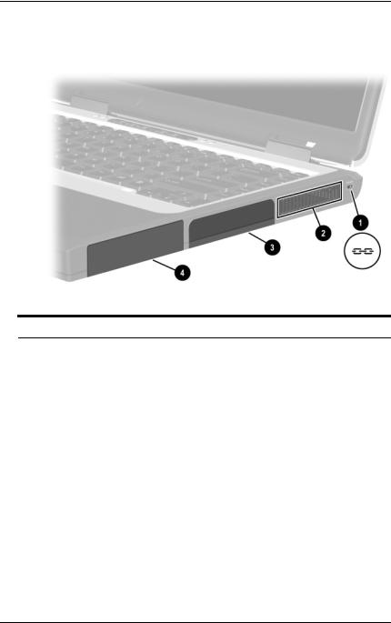
Identifying External Hardware
Right Side Components
Right Side Components
1 |
Security cable slot |
Attaches an optional security cable to |
|
|
the notebook. |
|
|
|
2 |
Vent (1 of 3) |
Allows airflow to cool internal |
|
|
components. |
|
|
ÄTo prevent overheating, do |
|
|
not obstruct the vent. Do not |
|
|
allow a hard surface, such as |
|
|
an adjoining optional printer, |
|
|
or a fabric, such as bedding |
|
|
or clothing, to block airflow. |
|
|
|
3 |
Hard drive bay |
Holds the primary hard drive. |
|
|
|
4 |
Battery bay |
Holds the primary battery pack. |
|
|
|
Hardware Guide |
1–13 |
Identifying External Hardware
Underside Components
Memory and Mini PCI Compartments
Underside Components: Memory and Mini PCI Compartments
1 |
Memory compartment |
Contains 2 memory slots for |
|
|
PC21000-compliant memory boards. |
|
|
As shipped, the memory |
|
|
compartment may contain 1 or 2 |
|
|
memory boards. |
|
|
|
2 |
Mini PCI (peripheral |
Supports an optional mini PCI board |
|
component interconnect) |
such as a modem board. (A modem |
|
compartment |
board is included with some notebook |
|
|
models.) |
|
|
|
1–14 |
Hardware Guide |
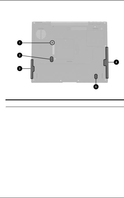
Identifying External Hardware
Bay Components
Underside Components: Bay Components
1 |
Hard drive bay retaining |
Secures the primary hard drive in the |
|
screw |
hard drive bay. |
|
|
|
2 |
Battery release latch |
Releases the primary battery pack |
|
|
from the battery bay. |
|
|
|
3 |
Battery bay recess |
Provides a grip area for removing |
|
|
a primary battery pack from the |
|
|
battery bay. |
|
|
|
4 |
MultiBay recess |
Provides a grip area for removing an |
|
|
optional MultiBay device from the |
|
|
MultiBay. |
|
|
|
5 |
MultiBay release latch |
Releases an optional MultiBay device |
|
|
from the MultiBay. |
|
|
|
Hardware Guide |
1–15 |
Identifying External Hardware
Vent and Docking Components
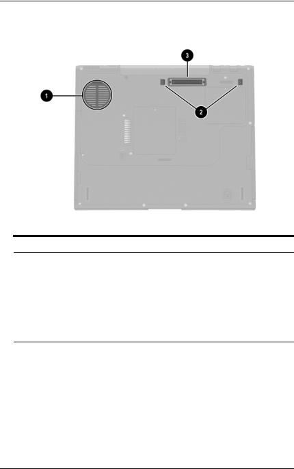
Underside Components: Vent and Docking Components
1 Vent (1 of 3) |
Provides airflow to cool internal |
|
components. |
|
ÄTo prevent overheating, do |
|
not obstruct the vent. Using |
|
the notebook on a soft |
|
surface, such as a pillow, |
|
blanket, rug, or thick clothing, |
|
may block airflow. |
2Docking latch recesses (2) Help secure the notebook to a port
|
replicator. |
|
|
3 Docking connector |
Connects the notebook to an optional |
|
port replicator. |
|
|
1–16 |
Hardware Guide |
Identifying External Hardware
Labels
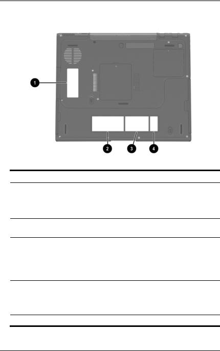
Underside Components: Labels
1Microsoft Certificate of Authenticity label*
Contains your Product Key number.
You may need this information to update or troubleshoot the operating system.
2 System label* |
Provides regulatory information about |
|
the notebook. |
3MultiPort agency approvals label* (models that ship with a wireless device only)
Lists the countries in which the wireless device has been approved for use.
You may need this information to use the wireless device while traveling.
4 Serial number* |
Identifies the notebook. You will need |
|
this number if you call Compaq |
|
customer support or download |
|
software from the Compaq Web site. |
*The appearance and position of labels varies by model.
Hardware Guide |
1–17 |
Identifying External Hardware
Additional Standard Components
The components included with the notebook vary by geographical region and the notebook hardware ordered. The following illustrations and tables identify the standard external components included with most notebook models.
These illustrations do not include printed documentation, supplementary software, or drives. The primary hard drive ships inside the hard drive bay. An optional MultiBay drive may ship inside the MultiBay.
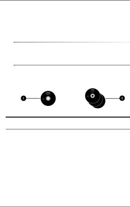
Documentation and Restore CDs
Additional Standard Components: Documentation and
Restore CDs
1 |
Documentation Library CD |
Includes the following guides: |
|
|
|
■ |
Hardware Guide |
|
|
■ |
Software Guide |
|
|
■ |
Modem and Networking |
|
|
■ |
Modem Command Guidelines |
|
|
|
(Advanced Users Only) |
|
|
■ |
Maintenance, Shipping and |
|
|
|
Travel |
|
|
■ |
Troubleshooting |
|
|
■ Regulatory and Safety Notices |
|
|
|
|
|
2 |
Restore CDs |
Contain the software preinstalled on |
|
|
|
the notebook. |
|
|
|
|
|
1–18 |
Hardware Guide |
Identifying External Hardware
Cord and Cables
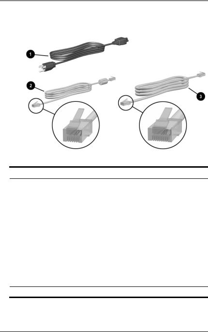
Additional Standard Components: Cord and Cables
1 |
Power cord* |
Connects the AC Adapter to an |
|
|
AC electrical outlet. |
|
|
|
2 |
Modem cable |
Connects the modem to an RJ-11 |
|
|
telephone jack or to a country-specific |
|
|
modem adapter. |
|
|
The modem cable has a |
|
|
6-pin RJ-11 telephone |
|
|
connector at each end. |
|
|
|
3 |
Network cable (select |
Connects the notebook to an |
|
models only) |
Ethernet network jack. |
The network cable has an 8-pin RJ-45 network connector at each end.
*Power cords vary in appearance by region.
Hardware Guide |
1–19 |
Identifying External Hardware
Adapters and Accessories
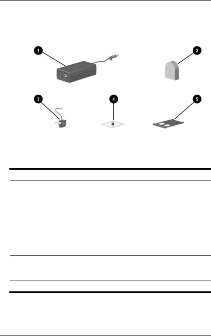
Additional Standard Components: Adapters and Accessories
1 |
AC Adapter* |
Converts AC power to DC power. |
|
|
|
2 |
Country-specific modem |
Adapts the modem cable to a |
|
adapter (included by region |
non-RJ-11 telephone jack. |
|
as required) |
|
|
|
|
3 |
Japan-specific outlet |
Connects the AC Adapter to a |
|
adapter (Japan only) |
2-prong electrical outlet. |
|
|
|
4 |
Spare pointing stick cap |
Replaces a worn pointing stick cap. |
|
(dual device models only) |
|
5Weight saver (may ship in MultiBay)
Can replace an optional MultiBay device to protect the MultiBay and reduce notebook weight
*AC Adapters vary in appearance by region.
1–20 |
Hardware Guide |
2
Pointing Devices and Keyboard
Pointing Devices
Pointing Devices on TouchPad Models Only
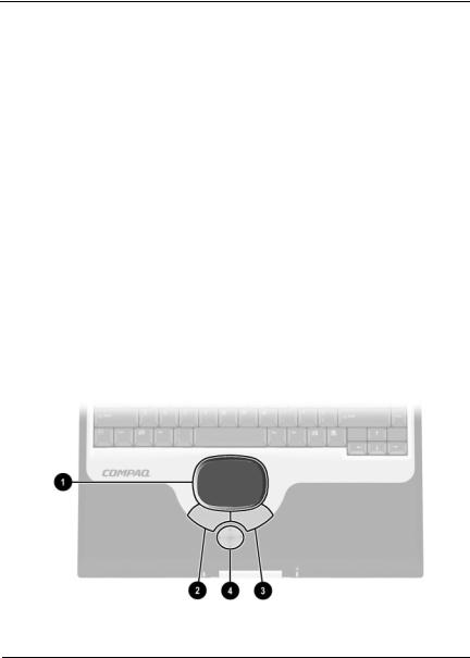
To move the cursor, sometimes called the pointer, slide your finger across the TouchPad surface 1 in the direction you want to move the cursor. If the cursor continues to move after you release the TouchPad, wait a few seconds and the cursor will stop moving.
Use the left 2 and right 3 TouchPad buttons as you would the left and right buttons on an external mouse.
Use the arrows on the scroll button 4 as you would the arrows on the scroll bars on the edges of windows. The scroll button moves the viewing area up, down, right, and left in Internet browser windows as well as most application windows.
Identifying TouchPad components
Hardware Guide |
2–1 |
Pointing Devices and Keyboard
Pointing Devices on Dual Device Models Only
The notebook is set at the factory to enable you to use the pointing stick and TouchPad components interchangeably. For information about disabling some or all dual device components, refer to “Enabling or Disabling Dual Device Components,” next in this section.
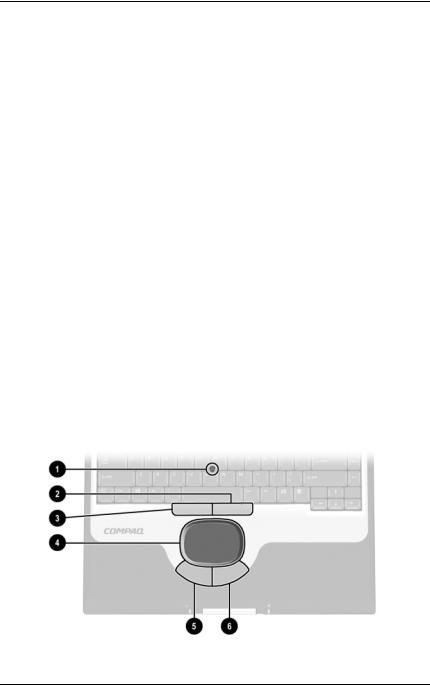
Using the Pointing Stick Components
To move the cursor, sometimes called the pointer, press the pointing stick 1 in the direction you want to move the cursor. To increase or decrease cursor speed, increase or decrease the directional (not downward) pressure on the pointing stick. If the cursor continues to move after you release the pointing stick, wait a few seconds and the cursor will stop moving.
Use the right 2 and left 3 pointing-stick buttons as you would the right and left buttons on an external mouse.
Using the TouchPad Components
To move the cursor, slide your finger across the TouchPad surface 4 in the direction you want to move the cursor.
Use the left 5 and right 6 TouchPad buttons as you would the left and right buttons on an external mouse.
Identifying dual device components
2–2 |
Hardware Guide |

Pointing Devices and Keyboard
Enabling or Disabling Dual Device Components
All dual device components are set at the factory to work interchangeably. For example, you can move the cursor with either the pointing-stick or the TouchPad.
You can set the notebook to respond to some, none, or all dual device components through the operating system.
To enable or disable dual device components:
1.Access the Mouse Properties window:
In Windows 2000 Professional, select Start > Settings > Control Panel > Mouse icon.
In Windows XP Home or Windows XP Professional, select Start > Control Panel > Printers and Other Hardware > Mouse icon.
2.Select the Advanced Features tab.
3.In the Devices list, select the device you want to enable or disable. Then:
To enable the device, select the Enable button.
To disable the device, select the Disable button.
4.Select the OK button.
Hardware Guide |
2–3 |
Loading...