


b
Maintenance and Service Guide
Compaq Evo Notebook N800c Series
Compaq Evo Notebook N800v Series
Compaq Evo Notebook N800w Series
Compaq Presario 2800 Mobile PC
Document Part Number: 268135-002
October 2002
This guide is a troubleshooting reference used for maintaining and servicing the notebook. It provides comprehensive information on identifying computer features, components, and spare parts, troubleshooting computer problems, and performing computer disassembly procedures.
© 2002 Compaq Information Technologies Group, L.P.
Compaq, the Compaq logo, Evo, and Presario are trademarks of Compaq Information Technologies Group, L.P. in the U.S. and/or other countries. Microsoft and Windows are trademarks of Microsoft Corporation in the U.S. and/or other countries. Intel, Pentium, and SpeedStep are trademarks of the Intel Corporation in the U.S. and/or other countries. All other product names mentioned herein may be trademarks of their respective companies.
Compaq shall not be liable for technical or editorial errors or omissions contained herein. The information in this document is provided “as is” without warranty of any kind and is subject to change without notice. The warranties for Compaq products are set forth in the express limited warranty statements accompanying such products. Nothing herein should be construed as constituting an additional warranty.
Maintenance and Service Guide
Second Edition October 2002
First Edition April 2002
Document Part Number: 268135-002

Contents
1 Product Description
1.1 Features . . . . . . . . . . . . . . . . . . . . . . . . . . . . . . . . . . . 1–2
1.2 Clearing a Password. . . . . . . . . . . . . . . . . . . . . . . . . . 1–4
1.3 Power Management . . . . . . . . . . . . . . . . . . . . . . . . . . 1–5
1.4 Computer External Components . . . . . . . . . . . . . . . . 1–6
1.5 Design Overview . . . . . . . . . . . . . . . . . . . . . . . . . . . 1–16
2 Troubleshooting
2.1 Computer Setup and Diagnostics Utilities . . . . . . . . . 2–1 Selecting Computer Setup or Compaq Diagnostics . 2–1 Selecting from the File Menu . . . . . . . . . . . . . . . . . . 2–3 Selecting from the Security Menu. . . . . . . . . . . . . . . 2–4 Selecting from the Advanced Menu . . . . . . . . . . . . . 2–5
2.2 Using Compaq Diagnostics . . . . . . . . . . . . . . . . . . . . 2–7 Obtaining, Saving, or Printing
Configuration Information. . . . . . . . . . . . . . . . . . . . . 2–7 Obtaining, Saving, or Printing Diagnostic
Test Information . . . . . . . . . . . . . . . . . . . . . . . . . . . . 2–8 2.3 Troubleshooting Flowcharts. . . . . . . . . . . . . . . . . . . 2–10
3 Illustrated Parts Catalog
3.1 Serial Number Location . . . . . . . . . . . . . . . . . . . . . . . 3–1
3.2 Computer System Major Components. . . . . . . . . . . . 3–2
3.3 Miscellaneous Plastics/Hardware Kit Components . 3–14
3.4 Mass Storage Devices . . . . . . . . . . . . . . . . . . . . . . . 3–16
3.5 Miscellaneous. . . . . . . . . . . . . . . . . . . . . . . . . . . . . . 3–18
Maintenance and Service Guide |
iii |

Contents
4 Removal and Replacement Preliminaries
4.1 Tools Required. . . . . . . . . . . . . . . . . . . . . . . . . . . . . . 4–1 4.2 Service Considerations. . . . . . . . . . . . . . . . . . . . . . . . 4–2 Plastic Parts . . . . . . . . . . . . . . . . . . . . . . . . . . . . . . . . 4–2 Cables and Connectors . . . . . . . . . . . . . . . . . . . . . . . 4–2 4.3 Preventing Damage to Removable Drives . . . . . . . . . 4–3 4.4 Preventing Electrostatic Damage . . . . . . . . . . . . . . . . 4–4 4.5 Packaging and Transporting Precautions . . . . . . . . . . 4–4 4.6 Workstation Precautions . . . . . . . . . . . . . . . . . . . . . . 4–5 4.7 Grounding Equipment and Methods . . . . . . . . . . . . . 4–6
5 Removal and Replacement Procedures
5.1 Serial Number . . . . . . . . . . . . . . . . . . . . . . . . . . . . . . 5–2 5.2 Disassembly Sequence Chart . . . . . . . . . . . . . . . . . . . 5–2 5.3 Preparing the Computer for Disassembly . . . . . . . . . 5–4 5.4 Computer Feet . . . . . . . . . . . . . . . . . . . . . . . . . . . . . . 5–9 5.5 Memory Expansion Board . . . . . . . . . . . . . . . . . . . . . 5–9 5.6 Mini PCI Communications Board . . . . . . . . . . . . . . 5–12 5.7 Connector Cover . . . . . . . . . . . . . . . . . . . . . . . . . . . 5–15 5.8 LED Cover . . . . . . . . . . . . . . . . . . . . . . . . . . . . . . . . 5–16 5.9 Keyboard . . . . . . . . . . . . . . . . . . . . . . . . . . . . . . . . . 5–18 5.10 Display . . . . . . . . . . . . . . . . . . . . . . . . . . . . . . . . . . 5–22 5.11 Top Cover. . . . . . . . . . . . . . . . . . . . . . . . . . . . . . . . 5–26 5.12 Speaker Assembly . . . . . . . . . . . . . . . . . . . . . . . . . 5–31 5.13 Display Release Assembly. . . . . . . . . . . . . . . . . . . 5–33 5.14 TouchPad . . . . . . . . . . . . . . . . . . . . . . . . . . . . . . . . 5–35 5.15 Fan . . . . . . . . . . . . . . . . . . . . . . . . . . . . . . . . . . . . . 5–38 5.16 Processor . . . . . . . . . . . . . . . . . . . . . . . . . . . . . . . . 5–40 5.17 Disk Cell RTC Battery. . . . . . . . . . . . . . . . . . . . . . 5–42 5.18 System Board . . . . . . . . . . . . . . . . . . . . . . . . . . . . . 5–44 5.19 Modem Cable. . . . . . . . . . . . . . . . . . . . . . . . . . . . . 5–49
iv |
Maintenance and Service Guide |

Contents
6 Specifications
AConnector Pin Assignments
BPower Cord Set Requirements
3-Conductor Power Cord Set . . . . . . . . . . . . . . . . . . . . . . B–1
General Requirements . . . . . . . . . . . . . . . . . . . . . . . . B–1
Country-Specific Requirements. . . . . . . . . . . . . . . . . . . . B–2
Notes . . . . . . . . . . . . . . . . . . . . . . . . . . . . . . . . . . . . . B–3
C Screw Listing
Index
Maintenance and Service Guide |
v |
1
Product Description
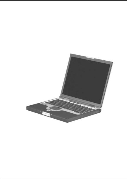
The Compaq Presario 2800 Series Mobile PC and Evo Notebook N800 Series offer advanced modularity, Intel Mobile Pentium 4 processors with SpeedStep technology with 64-bit architecture, industry-leading Accelerated Graphics Port (AGP) implementation, and extensive multimedia support.
Figure 1-1. Compaq Presario 2800 and Evo Notebook N800
Maintenance and Service Guide |
1–1 |

Product Description
1.1Features
■2.2-, 2.0-, 1.9-, 1.8-, 1.7-, 1.6-, 1.5-, or 1.4-GHz Intel Mobile Pentium 4 processor with SpeedStep technology, with 256-KB integrated L2 cache, varying by computer model
■ATI Mobile Radeon 9000 or ATI P7 graphics controller with 32 to 64 MB of shared SDRAM and 4X AGP graphics card, varying by computer model
■128-MB high-performance Synchronous DRAM (SDRAM), expandable to 1.0 GB
■Microsoft Windows 2000, Windows XP Home, or Windows XP Professional, varying by computer model
■15.0-inch UXGA (1600 × 1200), SXGA+ (1400 × 1050), or XGA (1024 × 768), or 14.1-inch XGA (1024 × 768),
TFT display with over 16.7 million colors, varying by computer model
■Full-size Windows 98 keyboard with:
TouchPad pointing device (Presario 2800 and Evo Notebook N800c models)
TouchPad and point stick (Evo Notebook N800c models only)
■Network interface card (NIC) integrated on the system board, with a mini PCI V.92 modem
■Integrated wireless support of 802.11b and Bluetooth devices through MultiPort
■Support for one Type I or II PC Card slot with support for both 32-bit CardBus and 16-bit PC Cards
■External 65 W AC adapter with power cord
■8-cell lithium ion (Li ion) battery pack
1–2 |
Maintenance and Service Guide |

Product Description
60-, 40-, 30-, or 20-GB high-capacity hard drive, varying by computer model
Support for the following drives through the MultiBay:
1.44-MB diskette drive
24X Max CD-ROM drive
8X Max CD-RW drive
8X Max DVD-ROM drive
8X Max DVD-CDRW combination drive
40or 30-GB hard drive
LS-120 drive
8-cell battery pack
Connectors for:
RJ-45 network
RJ-11 modem
Universal Serial Bus
Parallel devices
External monitor
AC power
Stereo line out/headphone
Mono microphone
S-video
Port replicator
Infrared
JBL Pro stereo speakers with bass reflex
Dolby Digital certified sound
Maintenance and Service Guide |
1–3 |

Product Description
1.2 Clearing a Password
If the notebook you are servicing has an unknown password, follow these steps to clear the password. These steps also clear CMOS:
1.Prepare the computer for disassembly (refer to Section 5.3, “Preparing the Computer for Disassembly,” for more information).
2.Remove the RTC battery (refer to Section 5.17, “Disk Cell RTC Battery”).
3.Wait approximately five minutes.
4.Replace the RTC battery and reassemble the computer.
5.Connect AC power to the computer. Do not reinsert any battery packs at this time.
6.Turn on the computer.
All passwords and all CMOS settings have been cleared.
1–4 |
Maintenance and Service Guide |

Product Description
1.3 Power Management
The computer comes with power management features that extend battery operating time and conserve power. The computer supports the following power management features:
■Suspend
■Hibernation
■Setting customization by the user
■Hotkeys for setting level of performance
■Smart battery that provides an accurate battery power gauge
■Battery calibration
■Lid switch Suspend/resume
■Power/Suspend button
■Advanced Configuration and Power Management (ACP) compliance
Maintenance and Service Guide |
1–5 |
Product Description
1.4 Computer External Components
The external components on the front and right side of the computer are shown in Figure 1-2 and described in Table 1-6.
.
Figure 1-2. Front and Right Side Components
Table 1-6
Front and Right Side Components
Item |
Component |
Function |
|
|
|
1 |
Stereo speakers (2) |
Produce stereo sound. |
|
|
|
2 |
Power/Suspend light |
On: Power is turned on. |
|
|
Off: Power is turned off. |
|
|
Blinking: Computer is in Suspend mode. |
|
|
|
1–6 |
Maintenance and Service Guide |

Product Description
Table 1-6
Front and Right Side Components (Continued)
Item |
Component |
Function |
|
|
|
3 |
Display release latch |
Opens the computer. |
|
|
|
4 |
Battery light |
On: A battery pack is charging. |
|
|
Blinking: A battery pack that is the only |
|
|
available power source has reached a |
|
|
low-battery condition. |
|
|
|
5 |
Battery bay |
Accepts an 8-cell lithium ion (Li ion) |
|
|
battery pack. |
|
|
|
6 |
Hard drive bay |
Supports the removable primary hard drive. |
|
|
The hard drive is secured to the computer |
|
|
by one screw. |
|
|
|
7 |
Vent |
Allows airflow to cool internal components. |
|
Ä CAUTION: To prevent damage, the computer shuts down if an |
|
|
overheating condition occurs. Do not block the cooling vent. |
|
|
Avoid placing the computer on a blanket, rug, or other flexible |
|
|
surface that may cover the vent area. |
|
|
|
|
8 |
Security cable slot |
Attaches an optional security cable to the |
|
|
computer. |
|
|
|
Maintenance and Service Guide |
1–7 |
Product Description
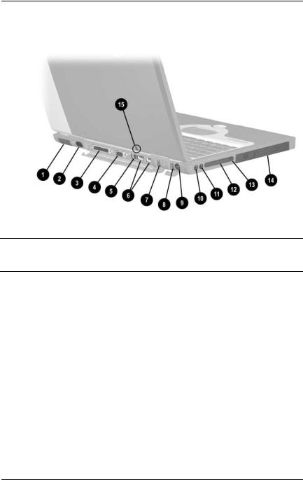
The computer rear panel and left side components are shown in Figure 1-3 and described in Table 1-7.
Figure 1-3. Rear Panel and Left Side Components
Table 1-7
Rear Panel and Left Side Components
Item |
Component |
Function |
|
|
|
1 |
Vent |
Allows airflow to cool internal components. |
|
CAUTION: To prevent damage, the computer shuts down if an |
|
|
overheating condition occurs. Do not block the cooling vent. |
|
|
Avoid placing the computer on a blanket, rug, or other flexible |
|
|
surface that may cover the vent area. |
|
|
|
|
2 |
Infrared port |
Provides wireless communication between |
|
|
the computer and another infrared- |
|
|
equipped device using an infrared beam. |
|
|
|
3 |
Parallel connector |
Connects a parallel device. |
|
|
|
1–8 |
Maintenance and Service Guide |

Product Description
Table 1-7
Rear Panel and Left Side Components (Continued)
Item |
Component |
Function |
|
|
|
|
|
4 |
External monitor |
Connects an external monitor or overhead |
|
|
connector |
projector. |
|
|
|
|
|
5 |
S-Video connector |
Connects a television, VCR, camcorder, or |
|
|
|
overhead projector. |
|
|
|
|
|
6 |
USB connectors (2) |
Connect USB devices. |
|
|
|
|
|
7 |
RJ-11 modem jack |
Connects the modem cable to an internal |
|
|
|
modem. A modem cable is included with |
|
|
|
internal modem models. |
|
|
|
|
|
8 |
RJ-45 network jack |
Connects the network cable. A network |
|
|
|
cable is not included with the computer. |
|
|
|
|
|
9 |
DC power jack |
Connects any one of the following: |
|
|
|
■ |
AC adapter |
|
|
■ |
Optional automobile power |
|
|
|
adapter/charger |
|
|
■ Optional aircraft power adapter |
|
|
|
|
|
10 |
Mono microphone jack |
Connects a mono microphone, disabling the |
|
|
|
built-in microphone. |
|
|
|
|
|
11 |
Stereo speaker/ |
Connects stereo speakers, headphones, |
|
|
headphone jack |
headset, or television audio. |
|
|
|
|
|
12 |
PC Card slot |
Supports a 32-bit (CardBus) or 16-bit PC |
|
|
|
Card. |
|
|
|
|
|
13 |
PC Card eject button |
Ejects a PC Card from the PC Card slot. |
|
|
|
|
|
14 |
MultiBay |
Accepts MultiBay devices, such as a |
|
|
|
diskette drive, optical drive, hard drive, |
|
|
|
or optional battery pack. |
|
|
|
|
|
Maintenance and Service Guide |
1–9 |

Product Description
The computer keyboard components are shown in Figure 1-4 and described in Table 1-8.
Figure 1-4. Keyboard Components
|
|
Table 1-8 |
|
|
Keyboard Components |
|
|
|
Item |
Component |
Function |
|
|
|
1 |
F1 through F12 |
Perform preset functions. |
|
function keys |
|
|
|
|
2 |
Num lock key |
On: Num lock is on and the embedded |
|
|
numeric keypad is enabled. |
|
|
|
1–10 |
Maintenance and Service Guide |

Product Description
Table 1-8
Keyboard Components (Continued)
Item |
Component |
Function |
|
|
|
3 |
Embedded numeric |
Converts keys to numeric keypad. |
|
keypad |
|
|
|
|
4 |
Cursor control keys |
Move the cursor around the screen. |
|
|
|
5 |
Windows application |
Displays a menu when using a Microsoft |
|
key |
application. The menu is the same one that |
|
|
is displayed by pressing the right mouse |
|
|
button. |
|
|
|
6 |
Windows logo keys |
Displays the Windows Start menu. |
|
|
|
7 |
Fn key |
Used with hotkeys to perform preset hotkey |
|
|
functions. |
|
|
|
Maintenance and Service Guide |
1–11 |
Product Description
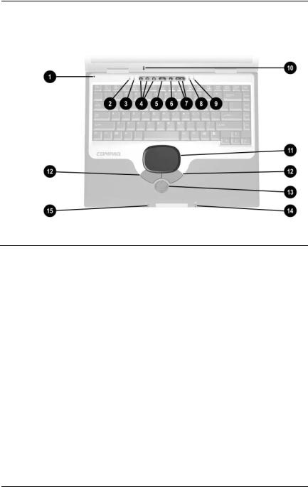
The computer top components are shown in Figure 1-5 and described in Table 1-9.
Figure 1-5. Top Components
|
|
Table 1-9 |
|
|
Top Components |
|
|
|
Item |
Component |
Function |
|
|
|
1 |
Display lid switch |
Turns off the computer display if the |
|
|
computer is closed while on. |
|
|
|
2 |
Power light |
On: Power is turned on. |
|
|
Blinking: Computer is in Suspend mode. |
|
|
The power light also blinks if a battery pack |
|
|
that is the only available power source |
|
|
reaches a low-battery condition. |
|
|
|
3 |
Num lock light |
On: Num lock is on and the embedded |
|
|
numeric keypad is enabled. |
|
|
|
4 |
Easy Access |
Provide quick access to the Internet. Refer |
|
Buttons (3) |
to the Hardware Guide that ships with the |
|
|
computer for information about these |
|
|
buttons. |
|
|
|
1–12 |
Maintenance and Service Guide |

Product Description
Table 1-9
Top Components (Continued)
Item |
Component |
Function |
|
|
|
5 |
Power button |
Turns on the computer. Use the operating |
|
|
system Shut Down command to turn off the |
|
|
computer. |
|
|
|
6 |
Digital audio button |
Launches Windows Media Player to play |
|
|
MP3 music. |
|
|
|
7 |
Volume control buttons |
Adjust the volume of the stereo speakers. |
|
|
|
8 |
Caps lock light |
On: Caps lock is on. |
|
|
|
9 |
Drive indicator light |
Turns on when the hard drive, CD-, or |
|
|
DVD-ROM drive is accessed. |
|
|
|
10 |
Microphone |
Allows for audio input. |
|
|
|
11 |
TouchPad |
Moves the mouse cursor, selects, and |
|
|
activates. |
|
|
|
12 |
TouchPad buttons |
Function like the left and right mouse |
|
|
buttons on an external mouse. |
|
|
|
13 |
EasyScroll |
Scrolls the screen left, right, up, and down. |
|
|
|
14 |
Battery power light |
On: A battery pack is charging. |
|
|
Blinking: A battery pack that is the only |
|
|
available power source has reached a |
|
|
low-battery condition. |
|
|
|
15 |
Power/Suspend light |
On: Power is turned on. |
|
|
Off: Power is turned off. |
|
|
Blinking: Computer is in Suspend mode. |
|
|
|
Maintenance and Service Guide |
1–13 |
Product Description
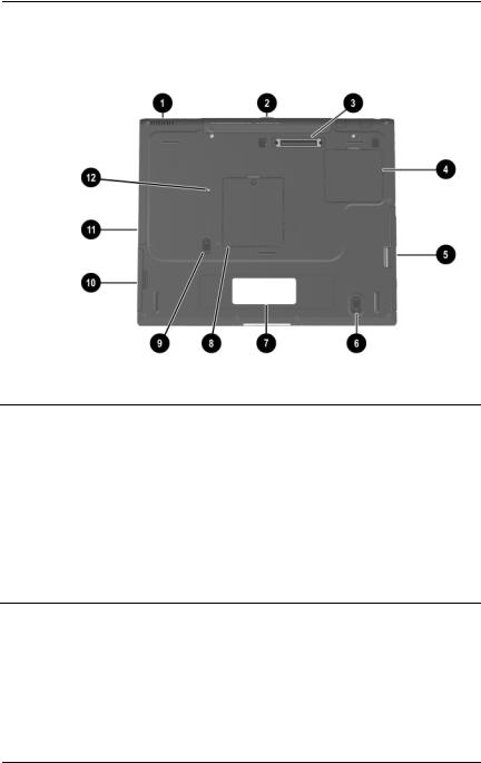
The external components on the bottom of the computer are shown in Figure 1-6 and described in Table 1-10.
Figure 1-6. Bottom Components
|
|
Table 1-10 |
|
|
Bottom Components |
|
|
|
Item |
Component |
Function |
|
|
|
1 |
Vent |
Allows airflow to cool internal |
|
|
components. |
CAUTION: To prevent damage, the computer shuts down if an overheating condition occurs. Do not block the cooling vent. Avoid placing the computer on a blanket, rug, or other flexible surface that may cover the vent area.
2 |
Connector cover |
Protects the parallel, external |
|
|
monitor, external keyboard/mouse, |
|
|
and USB connectors. |
|
|
|
3 |
Docking connector |
Connects the computer to an |
|
|
optional port replicator. |
|
|
|
1–14 |
Maintenance and Service Guide |

Product Description
Table 1-10
Bottom Components (Continued)
Item |
Component |
Function |
|
|
|
4 |
Mini PCI communications |
Contains the mini PCI modem |
|
compartment |
card. |
|
|
|
5 |
MultiBay |
Accepts a diskette drive, optical |
|
|
drive, hard drive, or battery pack. |
|
|
|
6 |
MultiBay release switch |
Releases the MultiBay device from |
|
|
the connector. |
|
|
|
7 |
Serial number |
Identifies the computer; needed |
|
|
when you call Compaq customer |
|
|
support. |
|
|
|
8 |
Memory expansion |
Covers the memory expansion |
|
compartment |
compartment that contains two |
|
|
memory expansion slots for |
|
|
memory expansion boards. |
|
|
|
9 |
Battery pack release switch |
Releases the battery pack from |
|
|
the battery compartment. |
|
|
|
10 |
Battery bay |
Accepts an 8-cell lithium ion |
|
|
(Li ion) battery pack. |
|
|
|
11 |
Hard drive bay |
Supports the primary hard drive. |
|
|
The hard drive is secured to the |
|
|
computer by one screw. |
|
|
|
12 |
Hard drive retention screw |
Secures the hard drive to the |
|
|
computer. |
|
|
|
Maintenance and Service Guide |
1–15 |
Product Description
1.5 Design Overview
This section presents a design overview of key parts and features of the computer. Refer to Chapter 3, “Illustrated Parts Catalog,” to identify replacement parts, and Chapter 5, “Removal and Replacement Procedures,” for disassembly steps. The system board provides the following device connections:
■Memory expansion board
■Hard drive
■Display
■Keyboard/TouchPad or pointing stick
■Audio
■Intel Mobile Pentium 4 processors with SpeedStep technology
■Fan
■PC Card
■Modem or modem/NIC
The computer uses an electrical fan for ventilation. The fan is controlled by a temperature sensor and is designed to turn on automatically when high temperature conditions exist. These conditions are affected by high external temperatures, system power consumption, power management/battery conservation configurations, battery fast charging, and software applications. Exhaust air is displaced through the ventilation grill located on the left side of the computer.
ÄCAUTION: To properly ventilate the computer, allow at least a 3-inch (7.6 cm) clearance on the left and right sides of the computer.
1–16 |
Maintenance and Service Guide |

2
Troubleshooting
ÅWARNING: Only authorized technicians trained by Compaq should repair this equipment. All troubleshooting and repair procedures are detailed to allow only subassembly/module level repair. Because of the complexity of the individual boards and subassemblies, no one should attempt to make repairs at the component level or to make modifications to any printed wiring board. Improper repairs can create a safety hazard. Any indication of component replacement or printed wiring board modification may void any warranty or exchange allowances.
2.1Computer Setup and Diagnostics Utilities
Selecting Computer Setup or Compaq Diagnostics
The computer features two Compaq system management utilities:
■Computer Setup—A system information and customization utility that can be used even when your operating system is not working or will not load. This utility includes settings that are not available in Windows.
Maintenance and Service Guide |
2–1 |

Troubleshooting
Compaq Diagnostics—A system information and diagnostic utility that is used within your Windows operating system. Use this utility whenever possible to:
Display system information.
Test system components.
Troubleshoot a device configuration problem in Windows 2000, Windows XP Professional, or Windows XP Home.
It is not necessary to configure a device connected to a USB connector on the computer or an optional docking base.
Using Computer Setup
Information and settings in Computer Setup are accessed from the File, Security, or Advanced menus:
1.Turn on or restart the computer. Press F10 while the F10 = ROM Based Setup message is displayed in the lower-left corner of the screen.
To change the language, press F2.
To view navigation information, press F1.
To return to the Computer Setup menu, press esc.
2.Select the File, Security, or Advanced menu.
3.To close Computer Setup and restart the computer:
Select File > Save Changes and Exit and press enter.
or
Select File > Ignore Changes and Exit and press enter.
4.When you are prompted to confirm your action, press F10.
2–2 |
Maintenance and Service Guide |

|
|
Troubleshooting |
|
|
|
|
|
Selecting from the File Menu |
|||
|
|
|
|
|
|
Table 2-1 |
|
|
|
File Menu |
|
|
|
|
|
|
Select |
To Do This |
|
|
|
|
|
|
System Information |
■ View identification information about the |
|
|
|
computer, a docking base, and any battery |
|
|
|
packs in the system. |
|
|
|
■ View specification information about the |
|
|
|
processor, memory and cache size, and |
|
|
|
system ROM. |
|
|
|
|
|
|
Save to Floppy |
Save system configuration settings to a diskette. |
|
|
|
|
|
|
Restore from Floppy |
Restore system configuration settings from a |
|
|
|
diskette. |
|
|
|
|
|
|
Restore Defaults |
Replace configuration settings in Computer |
|
|
|
Setup with factory default settings. (Identification |
|
|
|
information is retained.) |
|
|
|
|
|
|
Ignore Changes and Exit |
Cancel changes entered during the current |
|
|
|
session, then exit and restart the computer. |
|
|
|
|
|
|
Save Changes and Exit |
Save changes entered during the current |
|
|
|
session, then exit and restart the computer. |
|
|
|
|
|
Maintenance and Service Guide |
2–3 |

Troubleshooting
Selecting from the Security Menu
|
|
Table 2-2 |
|
|
Security Menu |
||
|
|
||
Select |
To Do This |
||
|
|
||
Setup Password |
Enter, change, or delete a setup password. |
||
|
(The setup password is called an administrator |
||
|
password in Compaq Computer Security, a |
||
|
program accessed from the Windows Control |
||
|
Panel.) |
||
|
|
||
Power-on Password |
Enter, change, or delete a power-on password. |
||
|
|
||
DriveLock Passwords |
Enable/disable DriveLock; change a DriveLock |
||
|
User or Master password. |
||
|
DriveLock Settings are accessible only |
||
|
|
when you enter Computer Setup by |
|
|
|
turning on (not restarting) the computer. |
|
|
|
||
Password Options |
Enable/Disable: |
||
Password options can be |
■ |
QuickLock |
|
selected only when a |
■ |
QuickLock on Suspend |
|
power-on password has |
|||
■ |
QuickBlank |
||
been set. |
|||
|
|
||
|
To enable QuickLock on Suspend or |
||
|
|
QuickBlank, you must first enable |
|
|
|
QuickLock. |
|
|
|
||
Device Security |
Enable/Disable: |
||
|
■ Ports or diskette drives* |
||
|
■ |
Diskette write* |
|
|
■ CD-ROM or diskette startup |
||
|
Settings for a DVD-ROM can be |
||
|
|
entered in the CD-ROM field. |
|
|
|
||
System IDs |
Enter identification numbers for the computer, |
||
|
a docking base, and all battery packs in the |
||
|
system. |
||
*Not applicable to SuperDisk LS-120 drives.
2–4 |
Maintenance and Service Guide |

Troubleshooting
Selecting from the Advanced Menu
|
Table 2-3 |
|
Advanced Menu |
|
|
Select |
To Do This |
|
|
Language (or press F2) |
Change the Computer Setup language. |
|
|
Boot Options |
Enable/Disable: |
|
■ QuickBoot, which starts the computer more |
|
quickly by eliminating some startup tests. |
|
(If you suspect a memory failure and want |
|
to test memory automatically during startup, |
|
disable QuickBoot.) |
|
■ MultiBoot, which sets a startup sequence |
|
that can include most bootable devices and |
|
media in the system. |
|
|
Device Options |
■ Enable/disable the embedded numeric |
|
keypad at startup. |
|
■ Enable/disable multiple standard pointing |
|
devices at startup. (To set the computer to |
|
support only a single, usually nonstandard, |
|
pointing device at startup, select Disable.) |
|
■ Enable/disable USB legacy support for a |
|
USB keyboard. (When USB legacy support |
|
is enabled, the keyboard works even when a |
|
Windows operating system is not loaded.) |
|
■ Set an optional external monitor or overhead |
|
projector connected to a video card in a |
|
docking base as the primary device. (When |
|
the computer display is set as secondary, |
|
the computer must be shut down before |
|
undocking from a docking base.) |
|
|
Maintenance and Service Guide |
2–5 |

Troubleshooting
|
Table 2-3 |
Advanced Menu (Continued) |
|
|
|
Select |
To Do This |
|
|
Device Options |
■ Change the parallel port mode from EPP |
(continued) |
(Enhanced Parallel Port [default]) to |
|
standard, bidirectional, EPP or ECP |
|
(Enhanced Capabilities Port). |
|
■ Set video-out mode to NTSC (default), PAL, |
|
NTSC-J, or PAL-M.* |
|
■ Enable/disable all settings in the SpeedStep |
|
window. (When Disable is selected, the |
|
computer runs in Battery Optimized mode.) |
|
■ Specify how the computer recognizes |
|
multiple identical docking bases that are |
|
identically equipped. (Select Disable to |
|
recognize the docking bases as a single |
|
docking base; select Enable to recognize |
|
the docking bases individually, by serial |
|
number.) |
|
■ Enable/disable the reporting of the |
|
processor serial number by the processor to |
|
the software. |
|
|
HDD Self Test Options |
Run a quick comprehensive self test on hard |
|
drives in the system that support the test |
|
features. |
*Video modes vary even within regions. However, NTSC is common in North America; PAL, in Europe, Africa, and the Middle East; NTSC-J, in Japan; and PAL-M, in Brazil. Other South and Central American regions may use NTSC, PAL, or PAL-M.
2–6 |
Maintenance and Service Guide |

Troubleshooting
2.2 Using Compaq Diagnostics
When you access Compaq Diagnostics, a scan of all system components is displayed on the screen before the Compaq Diagnostics window opens.
You can display more or less information from anywhere within Compaq Diagnostics by selecting Level on the menu bar.
Compaq Diagnostics is designed to test Compaq components. If non-Compaq components are tested, the results may be inconclusive.
Obtaining, Saving, or Printing
Configuration Information
1.Access Compaq Diagnostics by selecting Start > Settings >
Control Panel > Compaq Diagnostics.
2.Select Categories, then select a category from the drop-down list.
To save the information, select File > Save As.
To print the information, select File > Print.
3.To close Compaq Diagnostics, select File > Exit.
Maintenance and Service Guide |
2–7 |

Troubleshooting
Obtaining, Saving, or Printing Diagnostic Test Information
1.Access Compaq Diagnostics by selecting Start > Settings >
Control Panel > Compaq Diagnostics.
2.Select the Test tab.
3.In the scroll box, select the category or device you want to test.
4.Select a test type:
Quick Test—Runs a quick, general test on each device in a selected category.
Complete Test—Performs maximum testing on each device in a selected category.
Custom Test—Performs maximum testing on a selected device.
To run all tests for your selected device, select the
Check All button.
To run only the tests you select, select the Uncheck All button, then select the checkbox for each test you want to run.
2–8 |
Maintenance and Service Guide |

Troubleshooting
5.Select a test mode:
Interactive Mode—Provides maximum control over the testing process. You determine whether the test was passed or failed and may be prompted to insert or remove devices.
Unattended Mode—Does not display prompts. If errors are found, they are displayed when testing is complete.
6.Select the Begin Testing button.
7.Select a tab to view a test report:
Status tab—Summarizes the tests run, passed, and failed during the current testing session.
Log tab—Lists tests run on the system, the number of times each test has run, the number of errors found on each test, and the total run time of each test.
Error tab—Lists all errors found in the computer with their error codes.
8.Select a tab to save the report:
Log tab—Select the Log tab Save button.
Error tab—Select the Error tab Save button.
9.Select a tab to print the report:
Log tab—Select File > Save As, then print the file from your folder.
Maintenance and Service Guide |
2–9 |
 Loading...