


 Loading...
Compaq Deskpro Workstation AP250
Hardware Reference Guide

Deskpro Workstation AP250
Hardware Reference Guide

Notice
Compaq Computer Corporation shall not be liable for technical or editorial errors or omissions contained herein. The information in this guide is subject to change without notice.
© 2000 Compaq Computer Corporation. Except for use in connection with the accompanying Compaq product, no part of this guide may be photocopied or reproduced in any form without prior written consent from Compaq Computer Corporation.
COMPAQ, the Compaq logo, and Deskpro Registered in U.S. Patent and Trademark Office.
Microsoft, Windows, Windows NT, Windows 2000 Professional, and other names of Microsoft products referenced herein are trademarks or registered trademarks of Microsoft Corporation.
Intel and Pentium are registered trademarks of Intel Corporation.
All other product names mentioned herein may be trademarks or registered trademarks of their respective companies.
The following words and symbols mark special messages throughout this guide:
WARNING: Text set off in this manner indicates that failure to follow directions could result in bodily harm or loss of life.
CAUTION: Text set off in this manner indicates that failure to follow directions could result in damage to equipment or loss of information.
Compaq Deskpro Workstation AP250
Hardware Reference Guide
First Edition (June 2000)
Part Number 191009-001
Compaq Computer Corporation

CONTENTS |
|
chapter 1 |
|
Product Features |
|
Standard Configuration Features............................................................................................. |
1-1 |
Front Panel Components ......................................................................................................... |
1-2 |
Rear Panel Components .......................................................................................................... |
1-3 |
System Board Components ..................................................................................................... |
1-4 |
Changing from a Minitower to a Desktop Configuration ....................................................... |
1-5 |
Changing from a Desktop to a Minitower Configuration ....................................................... |
1-8 |
Windows Logo Key .............................................................................................................. |
1-11 |
Special Mouse Functions....................................................................................................... |
1-11 |
Serial Number Location ........................................................................................................ |
1-11 |
chapter 2 |
|
Hardware Upgrades |
|
Installation Sequence............................................................................................................... |
2-2 |
Removing the Workstation Access Panel................................................................................ |
2-3 |
Removing the Front Bezel....................................................................................................... |
2-4 |
Installing Additional Memory................................................................................................. |
2-5 |
Guidelines for RIMM Installation ..................................................................................... |
2-5 |
Installing RIMMs .............................................................................................................. |
2-6 |
Removing RIMMs............................................................................................................. |
2-7 |
Installing Additional Drives .................................................................................................... |
2-8 |
Drive Bay Components ..................................................................................................... |
2-8 |
Preparing for Drive Installation......................................................................................... |
2-9 |
Removing the Bezel Blank .......................................................................................... |
2-9 |
Installing a Drive ............................................................................................................. |
2-10 |
Installing a Hard Drive into a 3.5-inch Drive Bay..................................................... |
2-10 |
Installing a Hard Drive into a 5.25-inch Drive Bay................................................... |
2-12 |
Removing a Drive............................................................................................................ |
2-14 |
Installing and Removing an Expansion Board ...................................................................... |
2-16 |
Identifying the PCI and ISA Expansion Slots ................................................................. |
2-16 |
Installing an Expansion Board......................................................................................... |
2-17 |
Removing an Expansion Board ....................................................................................... |
2-18 |
Identifying the AGP Graphics Controller Expansion Slot............................................... |
2-19 |
Installing and Removing an AGP Graphics Controller ................................................... |
2-20 |
Installing a Processor ............................................................................................................ |
2-21 |
Attaching the Heatsink to the Processor.......................................................................... |
2-21 |
Installing the Processor/Heatsink Assembly.................................................................... |
2-24 |
Index..................................................................................................................................................... |
I-1 |
Compaq Deskpro Workstation AP250 Hardware Reference Guide iii

?D=FJAH
PRODUCT FEATURES
Standard Configuration Features
The Compaq™ Deskpro™ Workstation AP250 workstation is a minitower system that can be easily converted to a desktop. Features may vary depending on your model. For a complete listing of the hardware and software installed in your workstation, run the INSPECT utility described in the Troubleshooting Guide.
Compaq Deskpro Workstation AP250 Hardware Reference Guide 1-1
Front Panel Components
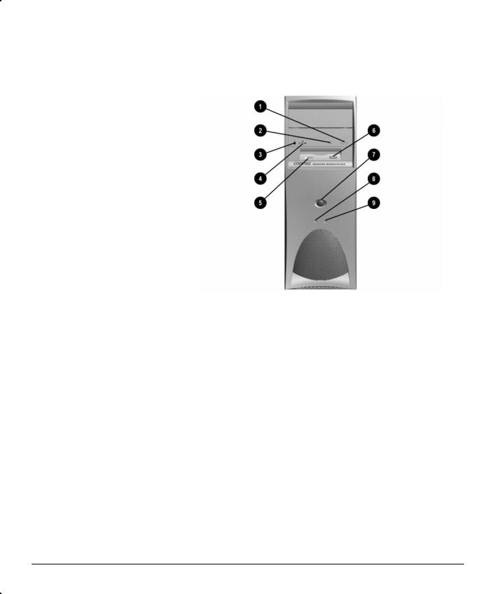
Front panel components
1 |
CD-ROM eject button |
2 |
CD-ROM drive activity light |
3 |
CD-ROM headphone jack |
4 |
CD-ROM volume |
5 |
Diskette drive activity light |
6 |
Diskette eject button |
7 |
Power button |
8 |
Power-on light |
9 |
Hard drive activity light |
1-2 Product Features

Rear Panel Components
Rear panel components
1Power cord connector
2Voltage select switch
3Two universal serial bus (USB) connectors
4Keyboard connector
5Mouse connector
6Serial connector (COMM1)
7Serial connector (COMM2)
8Headphone connector
9Line-out audio connector
:Parallel connector
;Microphone connector
ωLine-in audio connector
εVGA (AGP) video connector
ρExternal SCSI connector (on select models)
Compaq Deskpro Workstation AP250 Hardware Reference Guide 1-3

System Board Components
System board components
1ISA expansion slot
2Shared PCI/ISA expansion slot
3PCI expansion slots
4AGP expansion slot
5Primary processor
6RIMM slots 1-2
7Power connector
8Battery
9Diskette drive connector
−Secondary IDE connector
θPrimary IDE connector
ωPower switch and LED connector
εPower-on password (P49) enabled jumper
ρSW50 CMOS pushbutton switch
τWOL header connector
ψCD-ROM audio cable connector
1-4 Product Features
Changing from a Minitower to a Desktop Configuration
To change from a minitower to a desktop configuration:
1.Turn off the workstation and any external devices.
2.Disconnect the power cord from the grounded AC outlet and the back of the workstation, then disconnect the network cable from the system, and any external devices.
3.Remove the workstation access panel. Refer to “ Removing the Workstation Access Panel” in Chapter 2.
4.Remove the front bezel. Refer to “ Removing the Front Bezel” in Chapter 2.
5.Disconnect all power and data cables from the drives in the 5.25-inch drive bay.
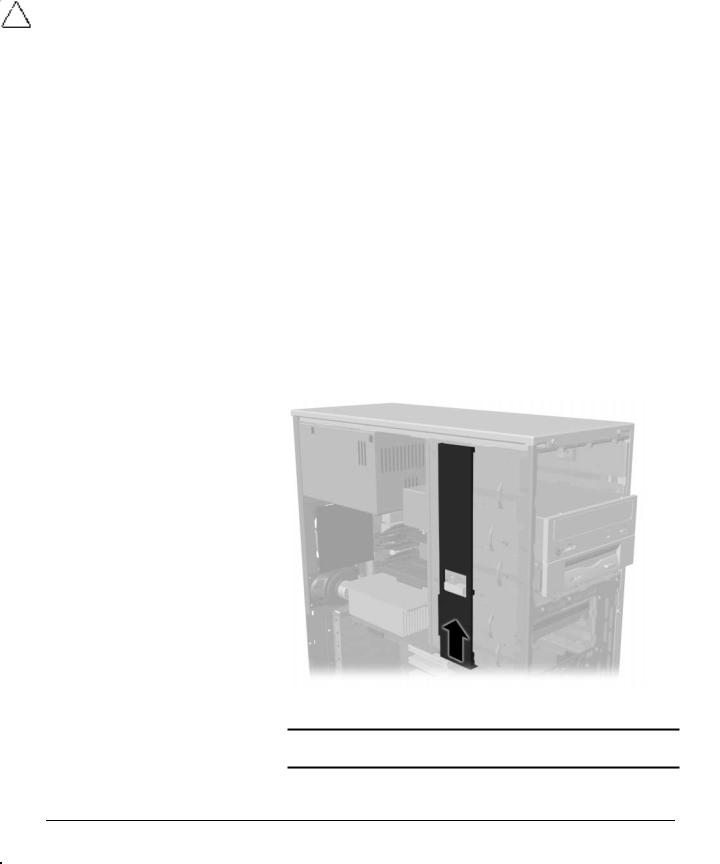
6.To release a drive from the 5.25-inch drive bay, slide the drivelock as shown. Carefully push the drive from the back of the unit until the drive casing can be grasped.
Releasing the drives with the drivelock
CAUTION: Do not hold the face plate while removing a drive. Only hold a drive by its casing.
7.While holding the drive casing, gently pull the drive out of the drive bay.
Compaq Deskpro Workstation AP250 Hardware Reference Guide 1-5

CAUTION: When removing the drives, do not pull the drives from the front of the drive bay. To prevent damage to the drive bezel, push the drives from the rear to remove them from the front of the drive bay.
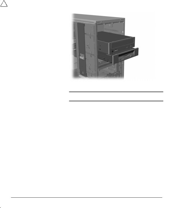
8.After placing the workstation in the desktop position, gently slide the drives back into the bay.
Installing the drives
CAUTION: The use of unnecessary force when installing the drive may result in damage to the drive.
Always place the diskette drive in the bay nearest the top (bay 3) of the chassis in the desktop configuration to ensure proper drive clearance and access. When all of the drives are properly inserted, the drivelock will secure the drives in place.
9.Reconnect the power and data cables to the drives as labeled.
1-6 Product Features
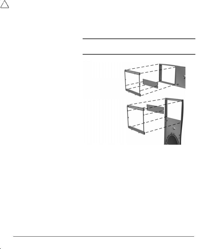
10.Remove the subpanel as described in the “ Removing the Bezel Blank” section in Chapter 2 and reposition the subpanel with the bezel blank in the proper orientation for the desktop configuration.
CAUTION: Hold the subpanel straight when you pull it away from the front bezel. Pulling the subpanel away at an angle could damage the pins that align it within the front bezel.
Changing from a minitower to a desktop configuration
11.Replace the subpanel, front bezel, and the workstation access panel. Be sure the subpanel and front bezel align properly with the alignment tabs.
When converting from a minitower to a desktop orientation, use the replacement bezel blank that was shipped with your workstation to ensure the Compaq logo is properly oriented.
12.Reconnect the power cord to the grounded AC outlet, then reconnect the network cable and any external devices to the system.
Compaq Deskpro Workstation AP250 Hardware Reference Guide 1-7

Changing from a Desktop to a Minitower Configuration
To change from a desktop to a minitower configuration:
1.Turn off the workstation and any external devices.
2.Disconnect the power cord from the grounded AC outlet and the back of the workstation, then disconnect the network cable from the system, and any external devices.
3.Remove the workstation access panel. Refer to “ Removing the Workstation Access Panel” in Chapter 2.
4.Remove the front bezel. Refer to “ Removing the Front Bezel” in Chapter 2.
5.Disconnect all power and data cables from the drives in the 5.25-inch drive bay.
6.To release a drive from the 5.25-inch drive bay, slide the drivelock as shown.
Releasing the drives with the drivelock
7.While pressing the drivelock button, push from the back of the drives until the drive casing can be grasped.
8.While holding the drive casing, pull the drives out of the drive bay.
9.After placing the workstation in the minitower position, gently slide the drives back into the bay.
1-8 Product Features
Installing the drives
CAUTION: The use of unnecessary force when installing the drives may damage the drives.
Always place the diskette drive in the bay nearest the internal 3.5-inch drives (bay 3) in the minitower configuration for proper clearance within the chassis. When the drives are properly inserted, the drivelock will secure them.
10.Reconnect the power and data cables to the drives as labeled.
Compaq Deskpro Workstation AP250 Hardware Reference Guide 1-9
11.Remove the subpanel as described in the “ Removing the Bezel Blank” section of Chapter 2 and reposition the subpanel with the bezel blank in the proper orientation for the minitower configuration.
CAUTION: Hold the subpanel straight when you pull it away from the front bezel. Pulling the subpanel away at an angle could damage the pins that align it within the front bezel.
Changing from a desktop to a minitower configuration
12.Replace the subpanel, front bezel, and workstation access panel. Be sure the subpanel and front bezel align properly with the alignment tabs.
When converting from a desktop to a minitower orientation, use the replacement bezel blank that is shipped with your workstation to ensure the Compaq logo is properly oriented.
13.Reconnect the power cord to the grounded AC outlet, then reconnect the network cable and any external devices to the system.
1-10 Product Features

Windows Logo Key
Use the Windows Logo key in combination with other keys to perform certain functions in Windows 2000 Professional and Windows NT Workstation 4.0.
Windows logo key + F1 |
Displays a pop-up menu for the |
|
selected object |
Windows logo key + Tab |
Activates the next Taskbar |
|
button |
Windows logo key + E |
Launches Explore My Computer |
Windows logo key + F |
Launches Find Document |
Windows logo key + Ctrl + F |
Launches Find Computer |
Windows logo key + M |
Minimizes all open applications |
Shift + Windows logo key + M |
Undoes Minimize All |
Windows logo key + R |
Displays Run dialog box |
Special Mouse Functions
Most software applications support the use of a mouse. The functions assigned to each mouse button depend on the software application you are using.
Serial Number Location
Each computer has a unique serial number located on the corner of the computer access panel and on the rear panel of the computer. Keep this number available when contacting Compaq customer service.
Compaq Deskpro Workstation AP250 Hardware Reference Guide 1-11

?D=FJAH
HARDWARE UPGRADES
This chapter explains how to remove the workstation access panel and the front bezel. It also explains how to install the following hardware:
■Memory
■Drives
■Expansion boards
■Processors
Compaq recommends that you finish the setup procedures for the preinstalled software before you install any optional hardware or third-party devices that were not included with your workstation.
Compaq Deskpro Workstation AP250 Hardware Reference Guide 2-1

Installation Sequence
Follow this sequence of steps to ensure the proper installation of any optional equipment. Before you begin, observe the following precautions:
!WARNING: To reduce the risk of personal injury from hot surfaces, allow the internal system components to cool before touching them.
!WARNING: To reduce the risk of electrical shock, fire, or damage to the equipment, do not plug telecommunications/telephone connectors into the network interface controller (NIC) receptacles.
CAUTION: Static electricity can damage the electronic components of the workstation or optional equipment. Before beginning these procedures, ensure that you are discharged of static electricity by briefly touching a grounded metal object.
1.Turn off the workstation and disconnect the power cord from the grounded AC outlet and the back of the workstation.
2.Disconnect the keyboard, monitor, network cable, and other external equipment connected to the workstation.
3.Open the workstation by removing its workstation access panel. See the section, “ Removing the Workstation Access Panel,” in this chapter for instructions.
4.If you are installing or removing drives in the front bays, see the section, “ Removing the Front Bezel,” in this chapter for instructions.
5.Install any optional equipment, such as memory, drives, expansion boards, processors, or batteries. See the appropriate sections in this chapter or the appendices for installation instructions. Also refer to the documentation provided with the optional equipment.
6.Replace the front bezel and the workstation access panel, if necessary.
7.Reconnect the keyboard, monitor, network cable, and other external devices.
8.Reconnect the power cord to the back of the workstation and plug the power cord into a grounded AC outlet.
9.Turn on the monitor, workstation, and any devices you installed.
10.Reconfigure the workstation, if necessary.
11.Test the workstation (optional) using the TEST utility.
2-2 Hardware Upgrades

Removing the Workstation Access Panel
To remove the workstation access panel:
1.Turn off the workstation and any external devices.
2.Disconnect the power cord from the grounded AC outlet and the back of the workstation.
3.Refer to the following illustration to remove the workstation access panel.
Loosening the two thumbscrews and removing the workstation access panel
When replacing the workstation access panel, be sure to tighten both thumbscrews.
Compaq Deskpro Workstation AP250 Hardware Reference Guide 2-3
Removing the Front Bezel
To remove the front bezel:
1.Turn off the workstation and any external devices.
2.Disconnect the power cord from the grounded AC outlet and the back of the workstation.
3.Remove the workstation access panel. Refer to “ Removing the Workstation Access Panel” in this chapter.
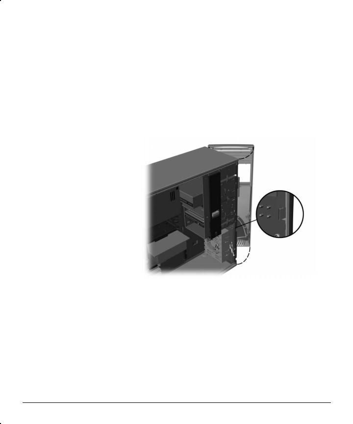
4.Push in on the two front bezel release tabs, then rotate the front bezel away from the chassis to release it.
Pressing the front bezel release tabs to remove the front bezel
When replacing the front bezel, ensure that the bottom hinge points are properly placed in the chassis before rotating the front bezel back into its original position.
2-4 Hardware Upgrades

Installing Additional Memory
The Compaq Deskpro Workstation AP250 workstation supports Error Checking and Correcting (ECC) Direct Rambus inline memory modules (RIMMs). Additional RIMMs are available to upgrade the memory. A maximum of 32 count Direct RDRAM devices is supported on each Direct Rambus memory channel. Continuity RIMMs (CRIMMs) must populate any empty slots.
Guidelines for RIMM Installation
When installing RIMMs, you must follow the guidelines listed below:
■A RIMM can be installed only one way. Be sure to match the two key slots on the RIMM with the tabs on the RIMM socket. Push the RIMM down into the RIMM socket, ensuring that it is fully inserted and properly seated, and that the retaining arms are locked in place.
■For optimal performance, install RIMMs in Slot 1, then Slot 2, and so on.
■CRIMMs must be installed in all empty RIMM sockets. The CRIMMs are removed when you populate the sockets with RIMMs.
■Never populate Slot 1 with a CRIMM. The correct configurations are:
Slot 1 (RIMM) and Slot 2 (CRIMM), or
Slot 1 (RIMM) and Slot 2 (RIMM)
■Do not exceed 32-count Direct RDRAM devices on each Direct Rambus memory channel. A label on the RIMM will indicate the number of Direct RDRAM devices on the RIMM and their speed.
You cannot remove or add Direct RDRAMS to a RIMM because the Direct RDRAMS are soldered on and encased by another material.
■Do not mix RIMMs with different memory speeds. Performance will reflect the slowest speed RIMMs.
Compaq Deskpro Workstation AP250 Hardware Reference Guide 2-5
■For proper system operation, the RIMMs must be industrystandard, 168-pin, unbuffered RIMMs. The RIMMs must support CAS Latency 2 or 3 (CL = 2 or CL = 3). They also must contain the mandatory Joint Electronic Device Engineering Council (JEDEC) Serial Presence Detect (SPD) information.
CAUTION: Static electricity can damage the electronic components of the workstation or optional boards. Before beginning these procedures, ensure that you are discharged of static electricity by briefly touching a grounded metal object.
CAUTION: The above guidelines must be followed when installing
RIMMs or your workstation will not function.
CAUTION: When handling a memory module, do not touch any of the contacts. Doing so can damage the module.
Installing RIMMs
!WARNING: To reduce the risk of personal injury when replacing or removing RIMMs, allow the module being removed from the RIMM slot sufficient time to cool. RIMM temperatures can reach
100°C (212°F).
CAUTION: When handling a RIMM, do not touch any of the contacts. Doing so may damage the module.
CAUTION: Static electricity can damage the electronic components of the workstation or option boards. Before beginning these procedures, ensure that you are discharged of static electricity by briefly touching a grounded metal object.
Before installing additional RIMMs, read “ Guidelines for RIMM
Installation” in this chapter.
CRIMMs must be installed in all unpopulated RIMM slots.
2-6 Hardware Upgrades
To install a memory module:
1.Turn off the workstation and any external devices, then disconnect the power cord from the grounded AC outlet.
On a power-managed system, the power cord must be disconnected from the grounded AC outlet.
2.Remove the workstation access panel and locate the RIMM sockets.
CAUTION: Be sure to follow the correct configuration guidelines respective to your memory board or your system will not function.
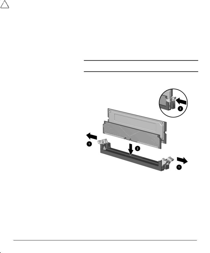
3.Using the following illustration as a guide, insert the RIMM module into the empty RIMM socket.
Installing a RIMM module
4.Replace the workstation access panel.
5.Plug the power cord back into the grounded AC outlet. Reconnect external devices.
6.Turn on the workstation. The workstation will automatically recognize the added memory.
Removing RIMMs
To remove a memory module from a RIMM slot, reverse the previous procedure.
Compaq Deskpro Workstation AP250 Hardware Reference Guide 2-7

Installing Additional Drives
Drive Bay Components
Your workstation supports up to five drive bays. See the following list for a description of the drive bay components.
Identifying drive bay components
Drive bays 1 through 3 are located on the front of the workstation. Bays 4 and 5 are located inside the workstation. The drives support various drive configurations.
1Bay 1 – 5.25-inch, half-height bay for optional drive
2Bay 2 – 5.25-inch, half-height bay for optional drive
3Bay 3 – 3.5-inch, high-density diskette drive mounted in the 5.25-inch, one-third height bay
4Bay 4 – 3.5-inch, one-third height bay for hard drive
5Bay 5 – 3.5-inch, one-third height bay for hard drive
Drive bay numbers are stamped on the chassis, behind the front bezel.
2-8 Hardware Upgrades
Loading...