


 Loading...
b
Hardware Reference Guide
Evo Desktop Family
Evo Workstation Family
Small Form Factor Models -
Intel Pentium 4 Version
Document Part Number: 243849-001
September 2001
This book provides basic information for upgrading this series of computers.

© 2001 Compaq Computer Corporation
Compaq, the Compaq logo, Armada, Deskpro Registered in U. S. Patent and Trademark Office.
Evo is a trademark of Compaq Information Technologies Group, L.P. in the United States and other countries.
Microsoft, MS-DOS, Windows, Windows NT are trademarks of Microsoft Corporation in the United States and other countries.
Intel, Pentium, Intel Inside, and Celeron are trademarks of Intel Corporation in the United States and other countries.
All other product names mentioned herein may be trademarks of their respective companies.
Compaq shall not be liable for technical or editorial errors or omissions contained herein. The information in this document is provided “as is” without warranty of any kind and is subject to change without notice. The warranties for Compaq products are set forth in the express limited warranty statements accompanying such products. Nothing herein should be construed as constituting an additional warranty.
Compaq service tool software, including associated documentation, is the property of and contains confidential technology of Compaq Computer Corporation. Service customer is hereby licensed to use the software only for activities directly relating to the delivery of, and only during the term of, the applicable services delivered by Compaq or its authorized service provider. Customer may not modify or reverse engineer, remove, or transfer the software or make the software or any resultant diagnosis or system management data available to other parties without Compaq’s or its authorized service provider’s consent. Upon termination of the services, customer will, at Compaq’s or its service provider’s option, destroy or return the software and associated documentation in its possession.
ÅWARNING: Text set off in this manner indicates that failure to follow directions could result in bodily harm or loss of life.
ÄCAUTION: Text set off in this manner indicates that failure to follow directions could result in damage to equipment or loss of information.
Printed in the U.S.A.
Hardware Reference Guide First Edition (September 2001)
Document Part Number: 243849-001

Contents
1 Product Features
Standard Configuration Features. . . . . . . . . . . . . . . . . . . . . . . . . . . . . . . . . . . . . . . . . . 1–1
Front Panel Components . . . . . . . . . . . . . . . . . . . . . . . . . . . . . . . . . . . . . . . . . . . . . . . . 1–2
Rear Panel Components . . . . . . . . . . . . . . . . . . . . . . . . . . . . . . . . . . . . . . . . . . . . . . . . 1–3
Using the Keyboard. . . . . . . . . . . . . . . . . . . . . . . . . . . . . . . . . . . . . . . . . . . . . . . . . . . . 1–4
Windows Logo Key . . . . . . . . . . . . . . . . . . . . . . . . . . . . . . . . . . . . . . . . . . . . . . . . 1–5
Special Mouse Functions. . . . . . . . . . . . . . . . . . . . . . . . . . . . . . . . . . . . . . . . . . . . . . . . 1–5
Serial Number Location . . . . . . . . . . . . . . . . . . . . . . . . . . . . . . . . . . . . . . . . . . . . . . . . 1–6
2 Hardware Upgrades
Installation Sequence. . . . . . . . . . . . . . . . . . . . . . . . . . . . . . . . . . . . . . . . . . . . . . . . . . . 2–1 Drawer Installation Method. . . . . . . . . . . . . . . . . . . . . . . . . . . . . . . . . . . . . . . . . . . . . . 2–2 Smart Cover Lock . . . . . . . . . . . . . . . . . . . . . . . . . . . . . . . . . . . . . . . . . . . . . . . . . . . . . 2–3 Using the Smart Cover FailSafe Key . . . . . . . . . . . . . . . . . . . . . . . . . . . . . . . . . . . 2–3 Removing the Computer Cover. . . . . . . . . . . . . . . . . . . . . . . . . . . . . . . . . . . . . . . . . . . 2–5 Installing Additional Memory . . . . . . . . . . . . . . . . . . . . . . . . . . . . . . . . . . . . . . . . . . . . 2–7 DIMMs . . . . . . . . . . . . . . . . . . . . . . . . . . . . . . . . . . . . . . . . . . . . . . . . . . . . . . . . . . 2–7 Memory Module Installation . . . . . . . . . . . . . . . . . . . . . . . . . . . . . . . . . . . . . . . . . 2–8 Removing the Expansion Card Cage. . . . . . . . . . . . . . . . . . . . . . . . . . . . . . . . . . . . . . 2–11 Installing an Expansion Card . . . . . . . . . . . . . . . . . . . . . . . . . . . . . . . . . . . . . . . . . . . 2–12 Removing the AGP Card. . . . . . . . . . . . . . . . . . . . . . . . . . . . . . . . . . . . . . . . . . . . . . . 2–15 Drive Positions . . . . . . . . . . . . . . . . . . . . . . . . . . . . . . . . . . . . . . . . . . . . . . . . . . . . . . 2–16 Installing Additional Drives . . . . . . . . . . . . . . . . . . . . . . . . . . . . . . . . . . . . . . . . . . . . 2–17 Upgrading the Hard Drive . . . . . . . . . . . . . . . . . . . . . . . . . . . . . . . . . . . . . . . . . . 2–17 Removing a CD-ROM Drive . . . . . . . . . . . . . . . . . . . . . . . . . . . . . . . . . . . . . . . . 2–19 Installing an Optional CD-ROM or DVD-ROM Drive . . . . . . . . . . . . . . . . . . . . 2–21
Hardware Reference Guide |
iii |

Contents
ASpecifications
BHard Drive Installation Guidelines
Using the Cable-Select Feature with Ultra ATA Devices. . . . . . . . . . . . . . . . . . . . . . . B–1 Guidelines for Installing Ultra ATA Devices . . . . . . . . . . . . . . . . . . . . . . . . . . . . . B–2 SCSI Devices. . . . . . . . . . . . . . . . . . . . . . . . . . . . . . . . . . . . . . . . . . . . . . . . . . . . . . . . . B–3 Guidelines for Using SCSI Devices . . . . . . . . . . . . . . . . . . . . . . . . . . . . . . . . . . . . B–3 Guidelines for Installing Optional SCSI Devices . . . . . . . . . . . . . . . . . . . . . . . . . . B–5 SCSI Controllers . . . . . . . . . . . . . . . . . . . . . . . . . . . . . . . . . . . . . . . . . . . . . . . . . . . B–5 SCSI Cables . . . . . . . . . . . . . . . . . . . . . . . . . . . . . . . . . . . . . . . . . . . . . . . . . . . . . . B–6 Using a SCSI Cable . . . . . . . . . . . . . . . . . . . . . . . . . . . . . . . . . . . . . . . . . . . . . . . . B–6 Using SCSISelect with SCSI Devices . . . . . . . . . . . . . . . . . . . . . . . . . . . . . . . . . . B–6 Choosing the Quiet Drive Options . . . . . . . . . . . . . . . . . . . . . . . . . . . . . . . . . . . . . . . . B–7
CBattery Replacement
DSecurity Lock Provisions
Installing a Security Lock . . . . . . . . . . . . . . . . . . . . . . . . . . . . . . . . . . . . . . . . . . . . . . . D–1
E Electrostatic Discharge
Preventing Electrostatic Damage . . . . . . . . . . . . . . . . . . . . . . . . . . . . . . . . . . . . . . . . . E–1
Grounding Methods. . . . . . . . . . . . . . . . . . . . . . . . . . . . . . . . . . . . . . . . . . . . . . . . . . . . E–1
F Routine Computer Care and Shipping Preparation
Routine Computer Care. . . . . . . . . . . . . . . . . . . . . . . . . . . . . . . . . . . . . . . . . . . . . . . . . F–1
CD-ROM Drive Precautions . . . . . . . . . . . . . . . . . . . . . . . . . . . . . . . . . . . . . . . . . . . . . F–2
Operation . . . . . . . . . . . . . . . . . . . . . . . . . . . . . . . . . . . . . . . . . . . . . . . . . . . . . . . . F–2
Cleaning . . . . . . . . . . . . . . . . . . . . . . . . . . . . . . . . . . . . . . . . . . . . . . . . . . . . . . . . . F–2
Safety . . . . . . . . . . . . . . . . . . . . . . . . . . . . . . . . . . . . . . . . . . . . . . . . . . . . . . . . . . . F–2
Shipping Preparation . . . . . . . . . . . . . . . . . . . . . . . . . . . . . . . . . . . . . . . . . . . . . . . . . . . F–3
Index
iv |
Hardware Reference Guide |

1
Product Features
Standard Configuration Features
The Compaq Evo™ Small Form Factor Personal Computer comes with features that may vary depending on your model. For a complete listing of the hardware and software installed in your computer, run Compaq Diagnostics for Windows or the INSPECT utility (available on some models). Instructions for using these utilities are provided in the Troubleshooting Guide on the Reference Library CD.
Hardware Reference Guide |
1–1 |

Product Features
Front Panel Components
Table for Front Panel Components
1 |
CD-ROM Drive Busy Indicator |
6 |
Optional Microphone Connector |
|
|
|
|
2 |
CD-ROM Eject Button |
7 |
Optional Stereo Headphone Jack |
|
|
|
(system) |
|
|
|
|
3 |
Power-On Light/Diagnostic LED |
8 |
Diskette Drive Activity Light |
|
|
|
|
4 |
Dual-State Power Button |
9 |
Diskette Eject Button |
|
|
|
|
5 |
Hard Drive Activity |
- |
Optional USB Connectors |
|
Light/Diagnostic LED |
|
|
|
|
|
|
1–2 |
Hardware Reference Guide |

Product Features
Rear Panel Components
Table for Rear Panel Components
1 |
Power Cord Connector |
6 |
Ethernet RJ-45 Connector |
|
|
|
|
2 |
Mouse Connector |
7 |
Parallel Connector |
|
|
|
|
3 |
Keyboard Connector |
8 |
Monitor Connector |
|
|
|
|
4 |
Universal Serial Bus (USB) Connector |
9 |
Line-out Connector |
|
|
|
|
5 |
Serial Connector (COM1) |
- |
Serial Connector (COM2) |
|
|
|
|
Hardware Reference Guide |
1–3 |

Product Features
Using the Keyboard
Compaq Enhanced Keyboard Components
1 |
Ctrl Key |
Used in combination with another key; its effect |
|
|
depends on the application software you are using. |
|
|
|
2 |
Windows Logo Key* |
Used to open the Start menu in Microsoft Windows. |
|
|
Used in combination with other keys to perform other |
|
|
functions. (See following section.) |
|
|
|
3 |
Alt Key |
Used in combination with another key; its effect |
|
|
depends on the application software you are using. |
|
|
|
4 |
Application Key* |
Used (like the right mouse button) to open pop-up |
|
|
menus in a Microsoft Office application. May perform |
|
|
other functions in other software applications. |
|
|
|
5 |
Editing Keys |
Includes the following: Insert, Home, Page Up, Delete, |
|
|
End, and Page Down. |
Holding down Ctrl and Alt while pressing Delete allows you to restart your computer.
*Keys available in select geographic regions.
1–4 |
Hardware Reference Guide |

Product Features
Compaq Enhanced Keyboard Components (Continued)
6 |
Num Lock light |
Indicates whether the Num Lock feature is on or off. |
|
|
|
7 |
Caps Lock light |
Indicates whether the Caps Lock feature is on or off. |
|
|
|
8 |
Scroll Lock light |
Indicates whether the Scroll Lock feature is on or off. |
|
|
|
Windows Logo Key
Use the Windows Logo Key in combination with other keys to perform certain functions available in the Windows operating systems.
Windows Logo Key + F1 |
Displays a pop-up menu for the selected object |
|
|
Windows Logo Key + Tab |
Activates the next Taskbar button |
|
|
Windows Logo Key + e |
Launches Explore My Computer |
|
|
Windows Logo Key + f |
Launches Find Document |
|
|
Windows Logo Key + Ctrl + f |
Launches Find Computer |
|
|
Windows Logo Key + m |
Minimizes all open applications |
|
|
Shift + Windows Logo Key + m |
Undoes Minimize All |
|
|
Windows Logo Key + r |
Displays the Run dialog box |
|
|
Special Mouse Functions
Most software applications support the use of a mouse. The functions assigned to each mouse button depend on the software applications you are using.
Hardware Reference Guide |
1–5 |
Product Features
Serial Number Location
Each computer has a unique serial number which may be located on the cover top or the side panel of the computer. Keep this number available for use when contacting Compaq customer service for assistance.
Serial Number Location
1–6 |
Hardware Reference Guide |
2
Hardware Upgrades
Installation Sequence
It is very important that you follow this sequence of steps to ensure the proper installation of any optional equipment.
For more information about Computer Setup, refer to the Computer
Setup Guide.
1.If your computer includes the Smart Cover Lock feature and you have set the lock, use Computer Setup to unlock the lock and disable the Smart Cover Sensor.
2.For more information about Computer Setup, refer to the
Computer Setup Guide.
3.If the computer is already on, turn it off and disconnect the power cord from the wall outlet.
ÅWARNING: To reduce the risk of personal injury from electrical shock and/or hot surfaces, be sure to disconnect the power cord from the wall outlet, and allow the internal system components to cool before touching.
ÅWARNING: To reduce the risk of electrical shock, fire, or damage to the equipment, do not plug telecommunications or telephone connectors into the network interface controller (NIC) receptacles.
ÄCAUTION: Static electricity can damage the electronic components of the computer or optional equipment. Before beginning these procedures, ensure that you are discharged of static electricity by briefly touching a grounded metal object. See Appendix E, “Electrostatic Discharge,” for more information.
Hardware Reference Guide |
2–1 |

Hardware Upgrades
4.Open the computer by removing its outside cover. See the procedures for removing the computer cover later in this chapter.
5.Install any optional equipment. See the applicable sections of this guide or refer to the documentation provided with the optional equipment for instructions.
6.Replace the computer cover.
7.Turn on the monitor, computer, and any devices you want to test.
8.Reconfigure the computer, if necessary. Refer to the Computer Setup Guide for instructions about using Computer Setup.
Drawer Installation Method
When installing the computer chassis in a drawer, the following conditions must be met to ensure proper air flow:
■At least 3 inches (7.6 cm) of clear space between the back of the drawer and anything behind it, such as a wall or the back panel of a desk.
■At least two 2-inch (5.1-cm) diameter holes in the back of the drawer. One hole must be immediately behind the power supply for exhaust air, and the other should be used for routing the cables.
ÄCAUTION: Cables should not be run through the exhaust air hole.
■At least nine holes in the front drawer panel or in the bottom of the drawer in front of the chassis for fresh air intake. The diameter of the holes must be between 0.38 and 0.5 inch (1.0 and 1.3 cm).
■At least 1 inch (2.54 cm) of clear space below the drawer to ensure proper air flow, if vent holes are located in the bottom of the mounting drawer.
■At least 1 inch (2.54 cm) of clear space above the top of the chassis.
2–2 |
Hardware Reference Guide |

Hardware Upgrades
Smart Cover Lock
The Smart Cover Lock is an optional feature and is available on select models only.
The Smart Cover Lock is a software-controllable cover lock, controlled by the setup password. This lock prevents unauthorized access to the internal components. The computer ships with the Smart Cover Lock in the unlocked position. For more information about locking the Smart Cover Lock, refer to the Desktop Management guide.
Using the Smart Cover FailSafe Key
If you enable the Smart Cover Lock and cannot enter your password to disable the lock, you will need a Smart Cover FailSafe Key to open the computer cover. You will need the key in any of the following circumstances:
■Power outage
■Startup failure
■PC component (for example, processor or power supply) failure
■Forgotten password
ÄCAUTION: The Smart Cover FailSafe Key is a specialized tool available from Compaq. Be prepared; order this key before you need one.
To obtain a FailSafe Key:
■Contact your authorized Compaq reseller or service provider.
■Refer to the Compaq Web site (www.compaq.com) for ordering information.
■Call the appropriate number listed in the warranty.
Hardware Reference Guide |
2–3 |
Hardware Upgrades
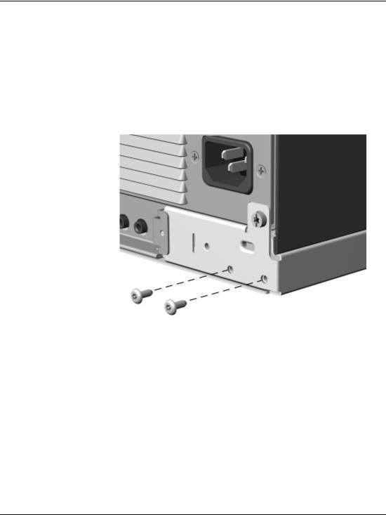
To open the computer cover:
1.Turn off the computer and any external devices.
2.Disconnect the power cord from the power outlet, and disconnect any external devices.
3.Using the Smart Cover FailSafe Key, remove the two tamper-proof screws that secure the Smart Cover Lock to the chassis.
Removing the Smart Cover Lock Screws
4. Remove the Smart Cover Lock.
To reattach the Smart Cover Lock, secure the lock in place with the tamper-proof screws.
2–4 |
Hardware Reference Guide |

Hardware Upgrades
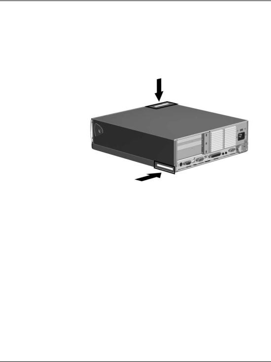
Removing the Computer Cover
To install optional equipment, you must remove the computer cover to gain access to internal components. The quick release cover latches located on the sides of the computer allow easy removal of the computer cover without the use of tools. To remove the cover, follow these steps:
1.If you have locked the Smart Cover Lock, refer to the previous section on Smart Cover Lock or use Computer Setup to unlock it.
2.Turn off the computer and any external devices.
3.Disconnect the power cord from the power outlet, and disconnect any external devices.
ÅWARNING: Before removing the computer cover, ensure that the computer is turned off and that the power cord is disconnected from the electrical outlet.
4.Press in the button on each side of the front bezel to release the quick release cover latches.
Hardware Reference Guide |
2–5 |

Hardware Upgrades
5.As you slide the computer cover forward, release the buttons and allow them to return to the original position, then lift the cover up and off the unit.
To replace the cover, reverse this procedure.
Removing the Computer Cover
2–6 |
Hardware Reference Guide |

Hardware Upgrades
Installing Additional Memory
The computer comes with synchronous dynamic random access memory (SDRAM) dual inline memory modules (DIMMs).
DIMMs
The memory sockets on the Intel 845 chipset-based system board can be populated with industry-standard DIMMs. These memory module slots are populated with at least one preinstalled memory module. To achieve the maximum memory support, you may be required to replace the preinstalled DIMM with a higher capacity DIMM.
For proper system operation, the DIMMs must be industry-standard 168-pin, PC133-compliant SDRAM DIMMs, depending on the model. The SDRAM DIMMs must support CAS Latency 2 or 3 (CL = 2 or CL = 3). They must also contain the mandatory Joint Electronic Device Engineering Council (JEDEC) Serial Presence Detect (SPD) information. DIMMs constructed with x4 SDRAM are not supported; the system will not start using unsupported DIMMs.
ÄCAUTION: Some models support ECC memory and some support non-ECC memory. For those systems that do support ECC, Compaq does not support mixing ECC and non-ECC memory. Doing so will cause the system to blink the NUMLOCK LED on the keyboard continuously and, if a speaker is installed in the system, there will be a short beep followed by 2 long beeps. In addition, the system will not boot the operating system.
Hardware Reference Guide |
2–7 |

Hardware Upgrades
Memory Module Installation
ÄCAUTION: Your memory module sockets have gold metal contacts. When upgrading your memory, it is important to use memory modules with gold metal contacts to prevent corrosion and/or oxidation resulting from having incompatible metals in contact with each other.
ÄCAUTION: Static electricity can damage the electronic components of the computer or optional cards. Before beginning these procedures, ensure that you are discharged of static electricity by briefly touching a grounded metal object. See Appendix E, “Electrostatic Discharge,” for more information.
ÄCAUTION: When handling a memory module, be careful not to touch any of the contacts. Doing so may damage the module.
1.If you have locked the Smart Cover Lock, use Computer Setup to unlock the lock.
2.Shut down the operating system properly, then turn off the computer and any external devices, then disconnect the power cord from the power outlet.
3.Remove the computer cover.
2–8 |
Hardware Reference Guide |
Loading...