


1905-24

i
HP V1905 Switch Series
Getting Started Guide
*5998-2235*
Part number: 5998-2235
Document version: 2

ii
HP V1905 Switch Series Getting Started Guide describes the appearance; installation, configuration, and
troubleshooting of the HP V1905 switch series.
This documentation set is intended for:
Network planners
Field technical support and servicing engineers
Network administrators working with the HP V1910 switches
Legal and notice information
© Copyright 2011 Hewlett-Packard Development Company, L.P.
No part of this documentation may be reproduced or transmitted in any form or by any means without prior
written consent of Hewlett-Packard Development Company, L.P.
The information contained herein is subject to change without notice.
HEWLETT-PACKARD COMPANY MAKES NO WARRANTY OF ANY KIND WITH REGARD TO THIS
MATERIAL, INCLUDING, BUT NOT LIMITED TO, THE IMPLIED WARRANTIES OF MERCHANTABILITY AND
FITNESS FOR A PARTICULAR PURPOSE. Hewlett-Packard shall not be liable for errors contained herein or
for incidental or consequential damages in connection with the furnishing, performance, or use of this
material.
The only warranties for HP products and services are set forth in the express warranty statements
accompanying such products and services. Nothing herein should be construed as constituting an
additional warranty. HP shall not be liable for technical or editorial errors or omissions contained herein.
Warranty
The Hewlett-Packard Limited Warranty Statement for this product and the HP Software License Terms which
apply to any software accompanying this product are available on the HP networking Web site at
http://www.hp.com/networking/warranty. The customer warranty support and services information are
available on the HP networking Web site at http://www.hp.com/networking/support. Additionally, your
HP-authorized network reseller can provide you with assistance, both with services that they offer and with
services offered by HP.

iii
Contents
Getting Started ····························································································································································· 1
Introducing the Switch ························································································································································· 1
Overview of the Switch ················································································································································· 1
Summary of Hardware Features ·································································································································· 1
Front View Detail ··························································································································································· 2
LED Status Indicators······················································································································································ 3
System Specifications ···················································································································································· 4
Installing the Switch ····························································································································································· 5
Before You Begin ··························································································································································· 5
Positioning the Switch ···················································································································································· 5
Rack-Mounting or Free-Standing ·································································································································· 6
Supplying Power to the Switch ····································································································································· 7
Checking for Correct Operation ·································································································································· 8
Using SFP Transceivers ·················································································································································· 8
Performing Spot Checks ············································································································································· 10
Configuring IP Address ···················································································································································· 10
Automatic IP Configuration using DHCP ·················································································································· 10
Manual IP Configuration ············································································································································ 10
Connecting To the Web Interface ····························································································································· 12
Requirements for Accessing the Web Interface ············································································································· 12
Choosing a Web Browser ··············································································································································· 12
Default User and Password ·············································································································································· 12
Logging On to the Web Interface ··································································································································· 13
Navigating the Web Interface ········································································································································ 13
Menu ············································································································································································ 13
Buttons ·········································································································································································· 16
Configuring the Switch ·············································································································································· 18
Configuring System Access ·············································································································································· 18
Defining System Access ············································································································································· 18
Modifying System Access ·········································································································································· 19
Removing System Access ··········································································································································· 20
Viewing System Access Settings ······························································································································· 20
Configuring IP and MAC Address Information ············································································································· 21
Defining IP Address ···················································································································································· 21
Configuring ARP Settings ··········································································································································· 21
Configuring MAC Address Table ····························································································································· 24
Configuring Port ································································································································································ 28
Configuring Port Basic Settings ································································································································· 28
Configuring PoE ·························································································································································· 31
Viewing Port Statistics ················································································································································ 34
Configuring VLAN ···························································································································································· 35
Creating VLANs ·························································································································································· 36
Modifying VLAN ························································································································································· 37
Modifying Port VLAN Settings ··································································································································· 38
Renaming VLANs ························································································································································ 38
Removing VLANs ························································································································································ 39

iv
Viewing VLAN Details ················································································································································ 39
Viewing VLAN Port Details ········································································································································ 40
Aggregating Port ······························································································································································ 41
Overview ····································································································································································· 41
LACP ············································································································································································· 41
Link Aggregation Types ·············································································································································· 41
Configuring Link Aggregation ··································································································································· 42
Configuring LACP ······················································································································································· 45
Configuring STP ································································································································································ 46
Configuring IGMP Snooping ··········································································································································· 52
Defining IGMP Snooping ··········································································································································· 52
Configuring ACL ······························································································································································· 53
Configuring MAC Based ACL ··································································································································· 53
Configuring IP Based ACL ········································································································································· 57
Configuring ACL Binding ··········································································································································· 62
Configuring QoS ······························································································································································ 64
Configuring CoS ························································································································································· 64
Configuring Queue Algorithm ··································································································································· 65
Configuring CoS to Queue ········································································································································ 66
Configuring DSCP to Queue ····································································································································· 67
Configuring Trust Mode ············································································································································· 69
Configuring Bandwidth Settings ································································································································ 69
Configuring Voice VLAN ··········································································································································· 71
Configuring SNMP ··························································································································································· 76
Defining SNMP Communities ···································································································································· 76
Removing SNMP Communities ·································································································································· 77
Defining SNMP Traps ················································································································································· 77
Removing SNMP Traps ·············································································································································· 78
Configuring LLDP ······························································································································································· 79
LLDP Overview ···························································································································································· 79
Configuring Global LLDP Parameters ······················································································································· 79
Configuring Port-Level LLDP Parameters ···················································································································· 80
Viewing LLDP Information ·········································································································································· 83
Managing Switch Security ··············································································································································· 85
Defining Port-Based Authentication (802.1X) ·········································································································· 85
Defining Radius Client ················································································································································ 89
Configuring LDB ·························································································································································· 89
Configuring Broadcast Storm Control ······················································································································ 93
Managing System Information ········································································································································ 94
Viewing Basic Settings ··············································································································································· 95
Configuring System Name ········································································································································· 96
Configuring System Time ··········································································································································· 97
Save Configuration ····················································································································································· 99
Resetting the Switch ···················································································································································· 99
Managing System Files ···················································································································································· 99
Managing System Logs ·················································································································································· 102
Configuring Logging ················································································································································· 103
Viewing Logs ····························································································································································· 104
Managing Switch Diagnostics ······································································································································· 105
Configuring Port Mirroring ······································································································································ 105
Configuring Cable Diagnostics ······························································································································· 106

v
Troubleshooting ······················································································································································· 108
Resetting to Factory Defaults ·········································································································································· 108
Forgotten Password ························································································································································ 108
Reset the switch ························································································································································· 108
Configure a new user ··············································································································································· 108
Forgotten Static IP Address ············································································································································ 109
Solving LED Issues ··························································································································································· 109
CLI Reference Guide ··············································································································································· 111
Getting Started with the Command Line Interface ······································································································· 111
Prerequisites ······························································································································································· 111
Logging on to the CLI ··············································································································································· 111
CLI Features ····································································································································································· 112
Online Help ······························································································································································· 112
Command History ····················································································································································· 113
Error Messages ························································································································································· 114
Command Edit ·························································································································································· 114
CLI Configuration ···························································································································································· 115
display ip ··································································································································································· 115
display management-vlan ········································································································································ 116
display version ·························································································································································· 116
ip address ·································································································································································· 117
ip address dhcp-alloc ··············································································································································· 117
ip gateway ································································································································································ 118
localuser ····································································································································································· 118
management-vlan ······················································································································································ 118
management-vlan port ·············································································································································· 119
ping ············································································································································································ 120
quit ·············································································································································································· 120
reboot ········································································································································································· 121
restore ········································································································································································ 121
save ············································································································································································ 122
tftp update ································································································································································· 122
Support and other resources ·································································································································· 123
Contacting HP ································································································································································· 123
Related information ························································································································································· 123
Conventions ····································································································································································· 123
Subscription service ························································································································································ 124
Glossary ··································································································································································· 125
Index ········································································································································································ 128

1
Getting Started
NOTE:
This manual applies to the HP V1905-48 Switch JD994A, HP V1905-24 Switch JD990A, and HP
V1905-24-PoE Switch JD992A, which are referred to as the Switch.
This manual uses the Web interfaces of the HP V1905-24-PoE Switch JD992A in the example text.
This chapter contains introductory information about the installation of the Switch and how the Switch can
be used in your network. It covers the following topics:
Introducing the Switch
Installing the Switch
Configuring IP Address
Introducing the Switch
This chapter covers summary information about the hardware and the following topics:
Overview of the Switch
Summary of Hardware Features
Front View Detail
LED Status Indicators
System Specifications
Overview of the Switch
The HP V1905-24 Switch JD990A is a versatile, easy-to-use configurable switch.
The HP V1905-24-PoE Switch JD992A is a versatile, easy-to-use configurable Power-over-Ethernet
(PoE) Switch.
The HP V1905-48 Switch JD994A is a versatile, easy-to-use configurable switch.
Each Switch is ideal for users who want the high-speed performance of 10/100 switching with the added
functionality of Gigabit copper and fiber links, but do not need sophisticated management capabilities. The
Switch is shipped ready for use. No configuration is necessary.
Summary of Hardware Features
Table 37 summarizes the hardware features supported by the Switch.
Table 37 Hardware Features
Feature Descri
p
tion
Addresses Up to 8192 supported.
Auto-negotiation Supported on all ports.
2
Feature Descri
p
tion
Forwarding Modes
Store and Forward.
Duplex Modes Half and full duplex on all front panel ports.
Auto MDI/MDIX
Supported on all ports. If fiber SFP transceivers are used, Auto
MDIX is not supported.
Flow Control In full duplex operation all ports are supported.
Traffic Prioritization Four traffic queues per port.
Ethernet Ports
10/100 Mbps ports.
Each port automatically determines the speed and duplex mode of
the connected equipment and provides a suitable switched
connection. The 10/100 Mbps ports can operate in either
half-duplex or full-duplex mode.
Gigabit Combo Ports
The 2 Gigabit combo ports support fiber Gigabit Ethernet
short-wave (SX) and long-wave (LX) SFP transceivers in any
combination. This offers you the flexibility of using SFP transceivers
to provide connectivity between the Switch and a 1000 Mbps core
network.
When an SFP port is in operation, the corresponding 1000BASE-T
port is disabled. The 1000 Mbps connections can only operate in
full duplex mode.
Mounting 19-inch rack or standalone mounting.
Fanless design (supported by HP
V1905-24 Switch JD990A and HP
V1905-48 Switch JD994A)
Silent operation whether used in a rack or desktop situation.
PoE (Only supported by HP
V1905-24-PoE Switch JD992A)
Each RJ-45 port supports the IEEE 802.3af PoE standard. Any
802.3af compliant device attached to a port can directly draw
power from the switch over the Ethernet cable without requiring its
own separate power source. This capability gives network
administrators centralized power control for devices such as IP
phones and wireless access points, which translates into greater
network availability.
Front View Detail
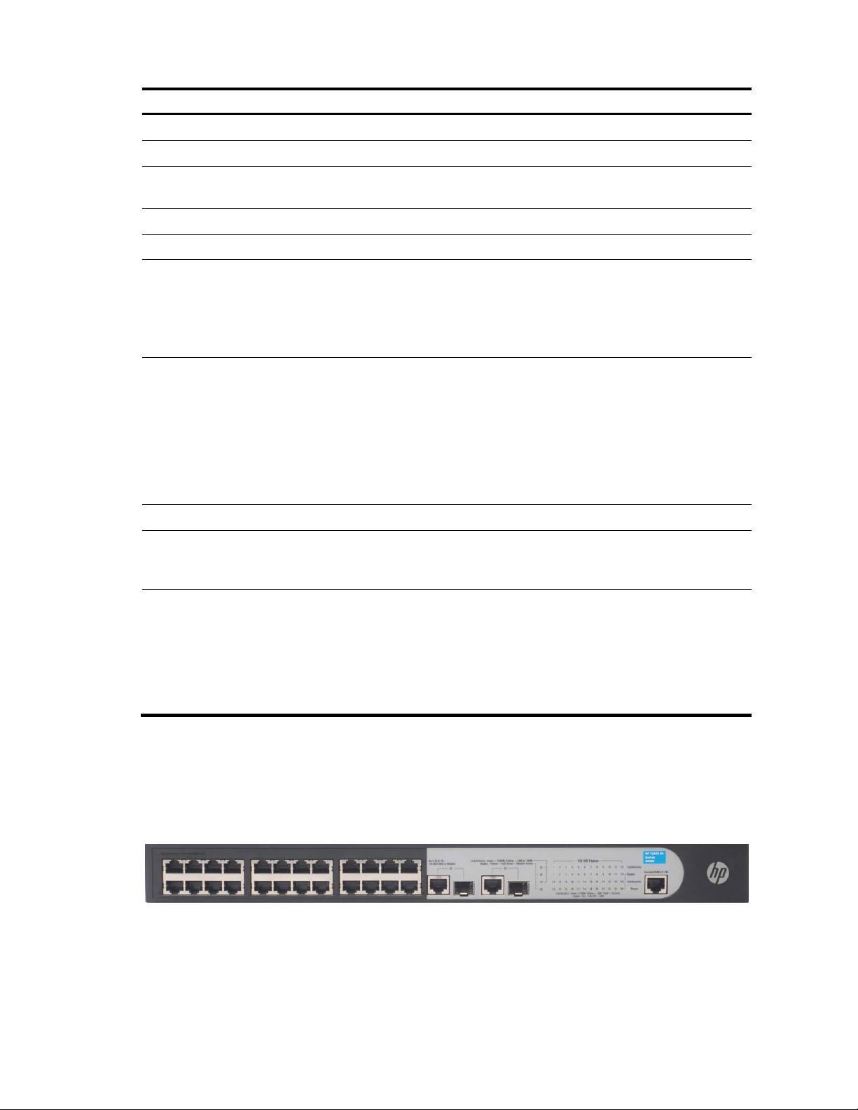
Figure 46 shows the front panel of the HP V1905-24 Switch JD990A 26-Port unit.
Figure 46 HP V1905-24 Switch JD990A 26-Port—front panel.
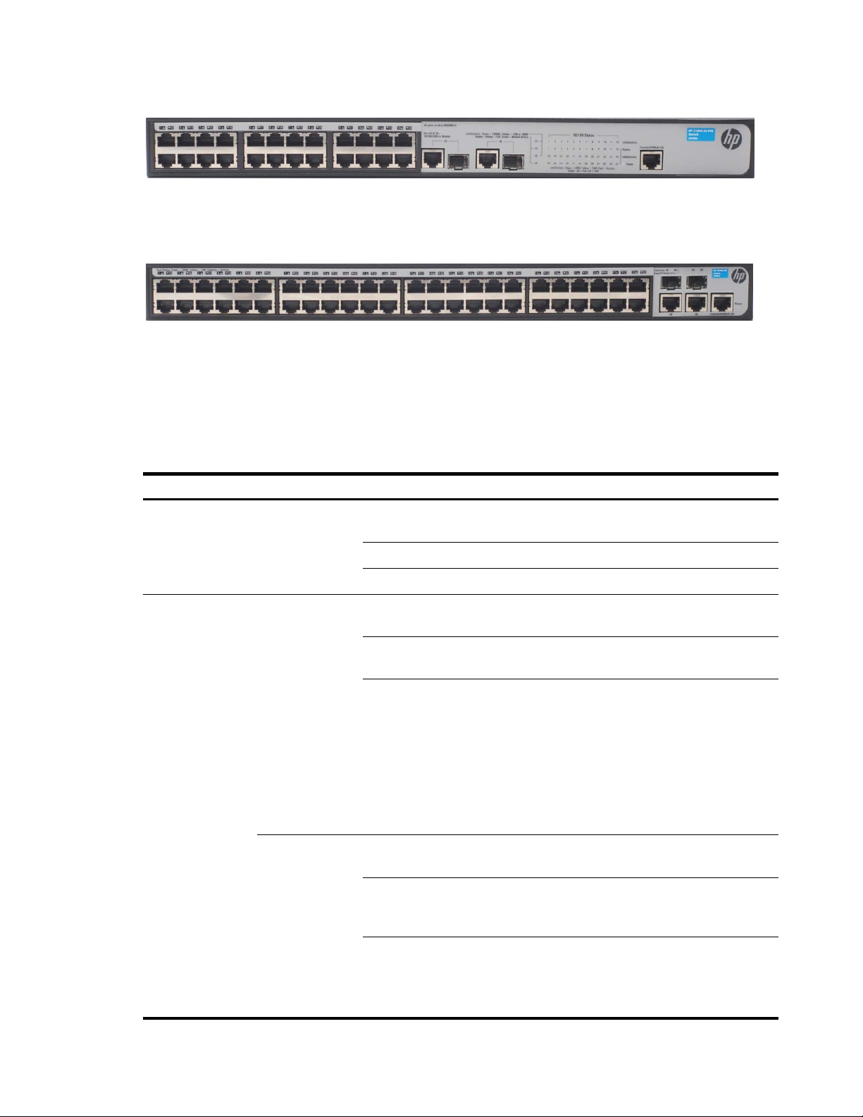
Figure 47 shows the front panel of the HP V1905-24-PoE Switch JD992A 26-Port unit.
3
Figure 47 HP V1905-24-PoE Switch JD992A 26-Port—front panel.
Figure 48 shows the front panel of the HP V1905-48 Switch JD994A 50-Port unit.
Figure 48 HP V1905-48 Switch JD994A 50-Port—front panel.
LED Status Indicators
The Switch provides LED indicators on the front panel to monitor the switch. Table 38 describes the
meanings of the LEDs.
Table 38 Description on the LEDs of the Switch
LED Status
Descri
p
tion
Power
Green
The switch starts normally. The LED flashes when the
system is performing Power-On Self-Test (POST).
Yellow The system has failed the POST.
OFF The switch is powered off.
Link/Activity
10/100BASE-T
port
Green
The port works at the rate of 100 Mbps; the LED flashes
quickly when the port is sending or receiving data.
Yellow
The port works at the rate of 10 Mbps; the LED flashes
quickly when the port is sending or receiving data.
OFF
The link has not been established, either nothing is
connected to the port, or there is a problem:
Check that the attached device is powered on.
Check that the cable is the correct type and is not
faulty.
If these checks do not identify the cause of the problem, it
may be that the unit or the device connected to the port is
faulty. Contact your supplier for further advice.
10/100/1000
BASE-T port
Green
The port works at the rate of 1000 Mbps; the LED flashes
quickly when the port is sending or receiving data.
Yellow
The port works at the rate of 10/100 Mbps; the LED
flashes quickly when the port is sending or receiving
data.
OFF
The link has not been established, either nothing is
connected to the port, or there is a problem:
Check that the attached device is powered on.
Check that the cable or fiber is the correct type and is

4
LED Status
Descri
p
tion
not faulty.
For fiber connections, ensure that the receive (RX) and
transmit (TX) cable connectors are not swapped.
If these checks do not identify the cause of the problem, it
may be that the unit or the device connected to the port is
faulty. Contact your supplier for further advice.
Duplex
10/100/1000
BASE-T port
Yellow The port is in full duplex mode.
OFF The port is not connected, or is in half duplex mode.
Module Active SFP port
Green The SFP module is inserted.
OFF The SFP module is not inserted or is not recognized.
PoE Power (Only supported by HP
V1905-24-PoE Switch JD992A)
Green The port is supplying power to the device connected to it.
OFF
The port is not supply power to the device connected to it
or not connected.
System Specifications
Table 39 contains the system specifications of the Switch.
Table 39 System specifications of the Switch.
S
p
ecification V1905-24
V1905-24-PoE
V1905-48
Physical dimensions
(H×W×D)
44 mm×440 mm×170
mm
44 mm×440 mm×238
mm
44 mm×440 mm×238
mm
Weight 1.6 kg 3.2 kg 2.9 kg
Console port 1 1 1
Ethernet port 24
24 (Each port can
provide a power
supply of 25 W)
48
Gigabit Combo port 2 2 2
AC Input voltage
Rated voltage range:
100–240V AC, 50/60
Hz
Rated voltage range:
100–240V AC, 50/60
Hz
Rated voltage range:
100–240V AC, 50/60
Hz
Power consumption (full
load)
17 W 205 W 26 W
Operating temperature 0°C to 40°C (32°F to 104°F)
Storage temperature –40°C to +70°C (–40°F to 158°F)
Operating humidity
(noncondensing)
5% to 95%
Storage humidity
(noncondensing)
5% to 95%

5
Installing the Switch
This section contains information that you need to install and set up the switch. It covers the following topics:
Before You Begin
Positioning the Switch
Rack-Mounting or Free-Standing
Supplying Power to the Switch
Checking for Correct Operation
Using SFP Transceivers
Performing Spot Checks
Before You Begin
Before installing or removing any components from the switch or carrying out any maintenance procedures,
read the Safety and Compliance Guide chapter in this guide.
Positioning the Switch
The switch is suitable for use in an office environment where it can be free-standing or mounted in a
standard 19-inch equipment rack.
Alternatively, the switch can be rack-mounted in a wiring closet or equipment room. A mounting kit,
containing two mounting brackets and four screws, is supplied with the switch.
When deciding where to position the switch, ensure that:
It is accessible and cables can be connected easily.
Cabling is away from sources of electrical noise. These include lift shafts, microwave ovens, and air
conditioning units. Electromagnetic fields can interfere with the signals on copper cabling and
introduce errors, thereby slowing down your network.
Water or moisture cannot enter the case of the unit.
Air flow around the unit and through the vents on the side of the case is not restricted (HP recommends
that you provide a minimum of 25 mm (1 in.) clearance).
The air is as free from dust as possible.
Temperature operating limits are not likely to be exceeded. HP recommends that the unit is installed in
a clean, air conditioned environment.
NOTE:
It is always good practice to wear an anti-static wrist strap connected to a ground point when installing
network equipment. If one is not available, try to keep in contact with a
g
rounded rack and avoid touchin
g
the unit's ports and connectors, if possible. Static discharge can cause reliability problems in your
equipment.
6
Rack-Mounting or Free-Standing
The unit can be mounted in a 19-inch equipment rack using the mounting kit or it can be free standing. Do
not place objects on top of the unit or stack.
CAUTION:
If installing the switch in a free-standing stack of different size Baseline or Super stack 3 units, the smaller
units must be installed above the larger ones. Do not have a free-standing stack of more than six units.
Using the Mounting Kit
The switch is supplied with two mounting brackets and four screws. These are used for rack mounting the
unit. When mounting the unit, refer to the guidelines given in Positioning the Switch.
The switch is 1U (1.7 inches) high and will fit in a standard 19-inch rack.
CAUTION:
Disconnect all cables from the unit before continuing. Remove the self-adhesive pads from the underside
of unit, if already fitted.
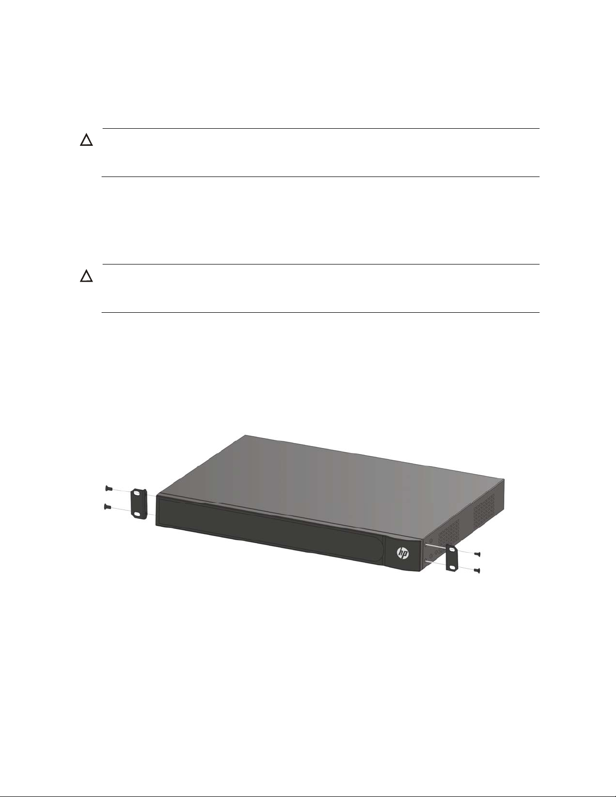
To rack-mount the switch:
1. Place the unit the right way up on a hard, flat surface with the front facing towards you.
2. Locate a mounting bracket over the mounting holes on one side of the unit.
3. Insert the two screws supplied in the mounting kit and fully tighten with a suitable screwdriver, as
shown in Figure 49.
Figure 49 Rack Mounting the Unit
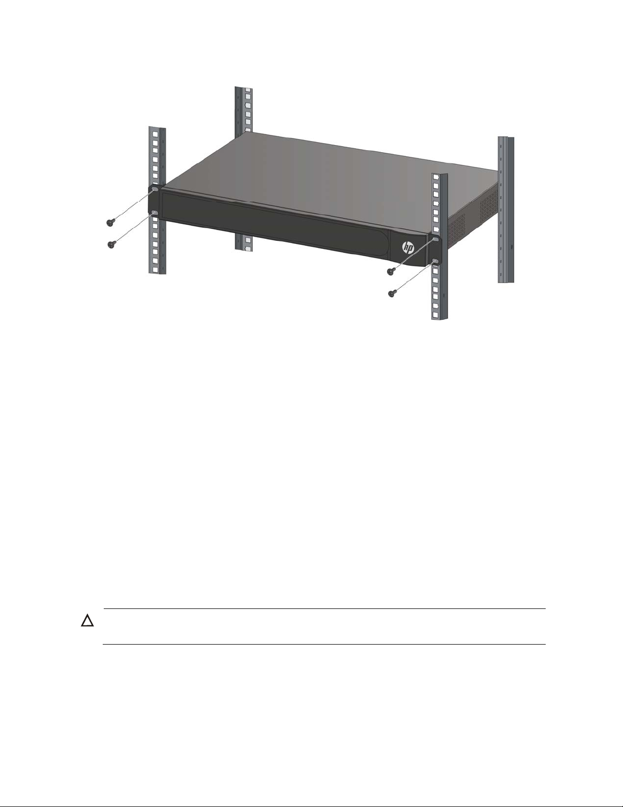
4. Insert the unit into the 19-inch rack and secure with suitable screws (not provided), as shown in Figure
50
7
Figure 50 Mount the HP V1905 Switch to a rack
5. Reconnect the cables.
Placing Units On Top of Each Other
If the switch units are free-standing, up to six units can be placed one on top of the other. If you are mixing
a variety of Baseline and Super Stack units, the smaller units must be positioned at the top.
If you are placing switch units one on top of the other, you must use the self-adhesive rubber pads supplied.
Apply the pads to the underside of each switch, sticking one in the marked area at each corner.
Place the switch units on top of each other, ensuring that the pads of the upper unit line up with the recesses
of the lower unit.
Supplying Power to the Switch
Power problems can be the cause of serious failures and downtime in your network. Ensure that the power
input to your system is clean and free from sags and surges to avoid unforeseen network outages. HP
recommends that you install power conditioning, especially in areas prone to blackout, power dips and
electrical storms.
The unit is intended to be grounded. Ensure it is connected to earth ground during normal use. Installing
proper grounding helps to avoid damage from lightning and power surges.
CAUTION:
Before powering on the switch, verify that the network cables and the power cable are securely connected.
To power on the switch:
1. Plug the power cord into the power socket on the rear panel of the switch.
2. Plug the other end of the power cord into a power outlet.

8
Checking for Correct Operation
After you power on the switch, it automatically performs a power-on self-test (POST). During POST, the
Power LED on the front panel of the switch flashes green.
When POST is complete, the Power LED turns green. If the Power LED turns yellow after POST, it means that
POST failed and the switch has entered its fail-safe mode.
The following summarizes the possible colors for the Power LED after POST.
Table 40 Summarizes the possible colors for the Power LED after POST
Status Meaning
Green The unit is powered on and ready for use.
Yellow
Power-on self-test or loop back test failed. The switch is in fail-safe mode. This can
happen if a port or ports fail when the switch was powered on.
Off
The unit is not receiving power.
Verify that the power cord is connected correctly, and then try powering on the
switch again
If the switch still does not operate, contact your HP network supplier
If POST fails, try the following:
Power off the switch, and then power it on again. Check the Power LED and see if POST was
successfully completed.
Reset the switch. See “Resetting to Factory Defaults.”
CAUTION:
Resetting the switch to its factory default erases all your settings. You will need to reconfigure the switch
after you reset it.
If these do not resolve the issue, please contact your HP network supplier for assistance.
Using SFP Transceivers
The following sections describe how to insert an SFP transceiver into an SFP slot.
NOTE:
SFP transceivers are hot-insertable and hot-swappable. You can remove them from and insert them into
any SFP port without having to power down the switch.
Inserting an SFP Transceiver
To be recognized as valid, the SFP transceiver must have the following characteristics:
1000BASE-SX or 1000BASE-LX media type:
1000BASE-SX SFP transceiver
Use this transceiver to connect the switch directly to a multimode fiber-optic cable.
1000BASE-LX SFP transceiver
9
Use this transceiver to connect the switch directly to a single mode fiber-optic cable or to multi-mode fiber
using a conditioned launch cable.
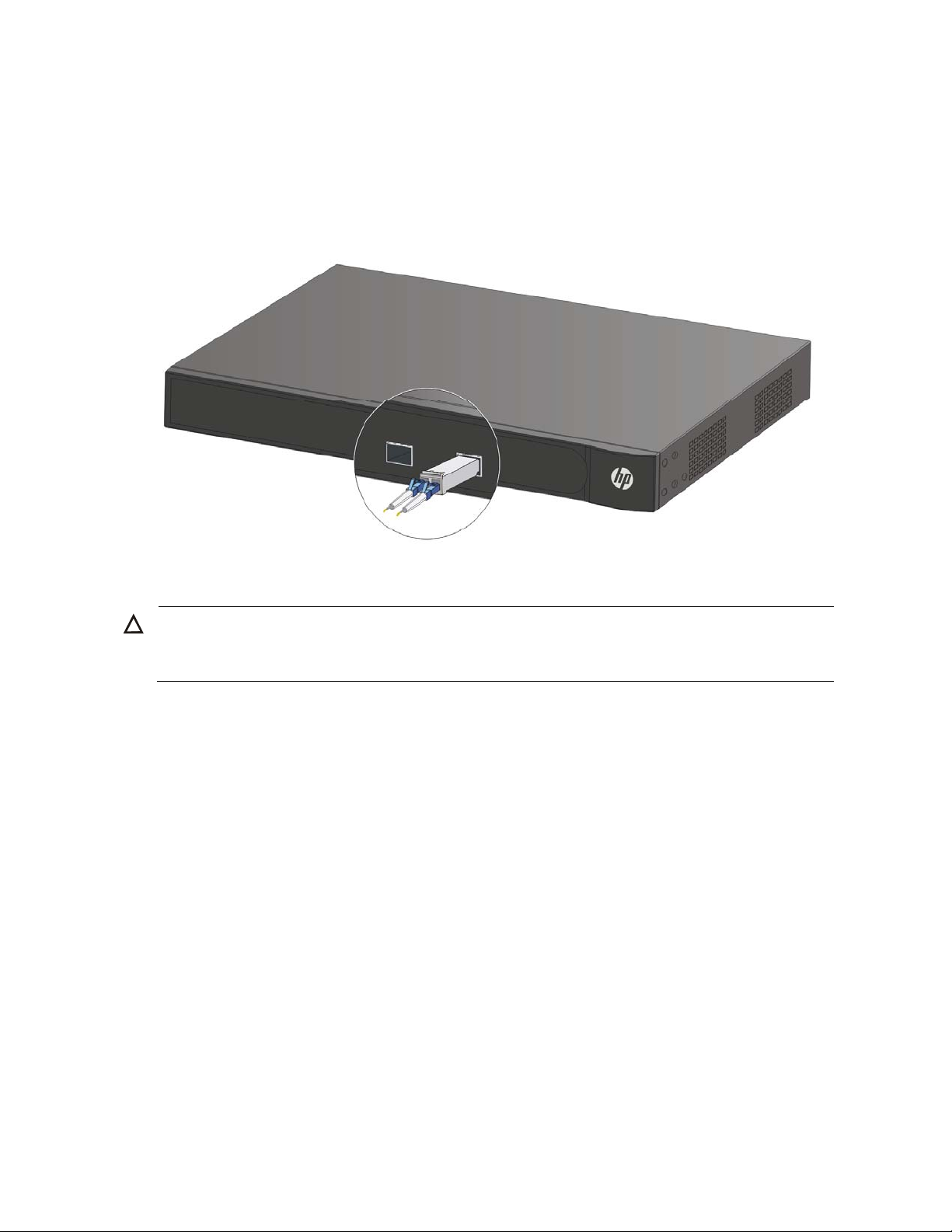
To activate the SFP port:
1. Hold the transceiver so that the fiber connector is toward you and the product label is visible, as shown
in Figure 51.Ensure the wire release lever is closed (in the upright position).
Figure 51 Inserting an SFP Transceiver
2. Gently slide the transceiver into the SFP slot until it clicks into place.
CAUTION:
SFP transceivers are keyed and can be properly inserted only one way. If the transceiver does not click
w
hen you insert it, remove it, turn it over, and reinsert it.
3. Remove the plastic protective cover, if fitted.
4. Connect the fiber cable.
5. Attach a male duplex LC connector on the network cable into the duplex LC connector on the
transceiver.
6. Connect the other end of the cable to a device fitted with an appropriate Gigabit Ethernet connection.
7. Check the Module Active LEDs on the front of the switch to ensure that the SFP transceiver is operating
correctly.
Removing an SFP Transceiver
To remove an SFP transceiver:
1. Disconnect the cable from the transceiver.
2. Move the wire release lever downwards until it is pointing toward you.
3. Pull the wire release lever toward you to release the catch mechanism.
The SFP transceiver should slide out easily.

10
Performing Spot Checks
At frequent intervals, you should visually check the switch. Regular checks can give you an early warning
of a possible failure; any problems can then be attended to when there will be least effect on users.
HP recommends periodically checking the items listed in Table 41.
Table 41 Items to Check
Item O
p
eration
Cooling fan
Where possible, check that the cooling fan is operating by listening to the unit. The fan
is fitted near to the front right hand side of the unit (when viewed from the front).
Cabling
Check that all external cabling connections are secure and that no cables are pulled
taut.
Configuring IP Address
The switch’s IP configuration is determined automatically using DHCP, or manually using values you assign.
By default, the switch will use its default IP information. The default IP address is 169.254.xxx.xxx. If the
MAC address is 08004E000102, the IP address would be 169.254.1.2.
Automatic IP Configuration using DHCP
When you use the automatic IP configuration method, the switch tries to obtain its IP information without
requesting user intervention from a DHCP server on the network.
You should use the automatic IP configuration method if:
Your network uses DHCP to allocate IP information, or
Flexibility is needed. If the switch is deployed onto a different subnet, it will automatically reconfigure
itself with an appropriate IP address, instead of you having to manually reconfigure the switch.
You can use ip address dhcp-alloc command to define automatic IP configuration method and use display
ip command to view the automatically allocated IP Information through the Console Port (see “CLI Reference
Guide”).
Manual IP Configuration
When you configure the IP information manually, the switch remembers the information that you enter until
you change it again.
You should use the manual IP configuration method if:
You do not have a DHCP server on your network, or
You want to remove the risk of the IP address ever changing, or
Your DHCP server does not allow you to allocate static IP addresses.

11
NOTE:
For most installations, HP recommends that you configure the switch IP information manually. This makes
management simpler and more reliable as it is not dependent on a DHCP server, and eliminates the risk
of the IP address changing.
You can use ip address command to configure the static IP for your switch through the Console Port (see “CLI
Reference Guide”).

12
Connecting To the Web Interface
The switch has a built-in Web interface that you can use to set the user password, change the IP address that
is assigned to the switch, and configure its advanced settings.
This chapter introduces the setting the menu items and buttons that are available on the Web interface. The
following topics are covered:
Requirements for Accessing the Web Interface
Choosing a Web Browser
Default User and Password
Logging On to the Web Interface
Navigating the Web Interface
Requirements for Accessing the Web Interface
To connect to the Web interface, you need the following:
Ensure that the switch is connected to the network using a Category 5 twisted pair Ethernet cable with
RJ-45 connectors.
Ensure that you know your switch’s IP address. See “Configuring IP Address”.
Check that your management workstation is on the same subnet as your switch.
Choose a suitable Web browser.
Choosing a Web Browser
To display the Web interface correctly, use one of the following Web browsers and platform combinations:
Table 42 Supported Web Browsers and Platforms
Browser Windows 2000
Windows XP
Windows Vista
Internet Explorer 6 Yes Yes Yes
Internet Explorer 7 Yes Yes Yes
Firefox 3 Yes Yes Yes
Netscape 8 Yes Yes Yes
For the browser to operate the Web interface correctly, JavaScript and Cascading Style Sheets must be
enabled on your browser. These features are enabled on a browser by default. You will only need to enable
them if you have changed your browser settings.
Default User and Password
If you intend to manage the switch or to change the default password, you must log in with a valid user
name and password. The switch has one default user name. The default user is listed in Table 43.
13
Table 43 Default User and Password
User Name Default Password
Access Level
admin -
Management: The user can access and change all
manageable parameters
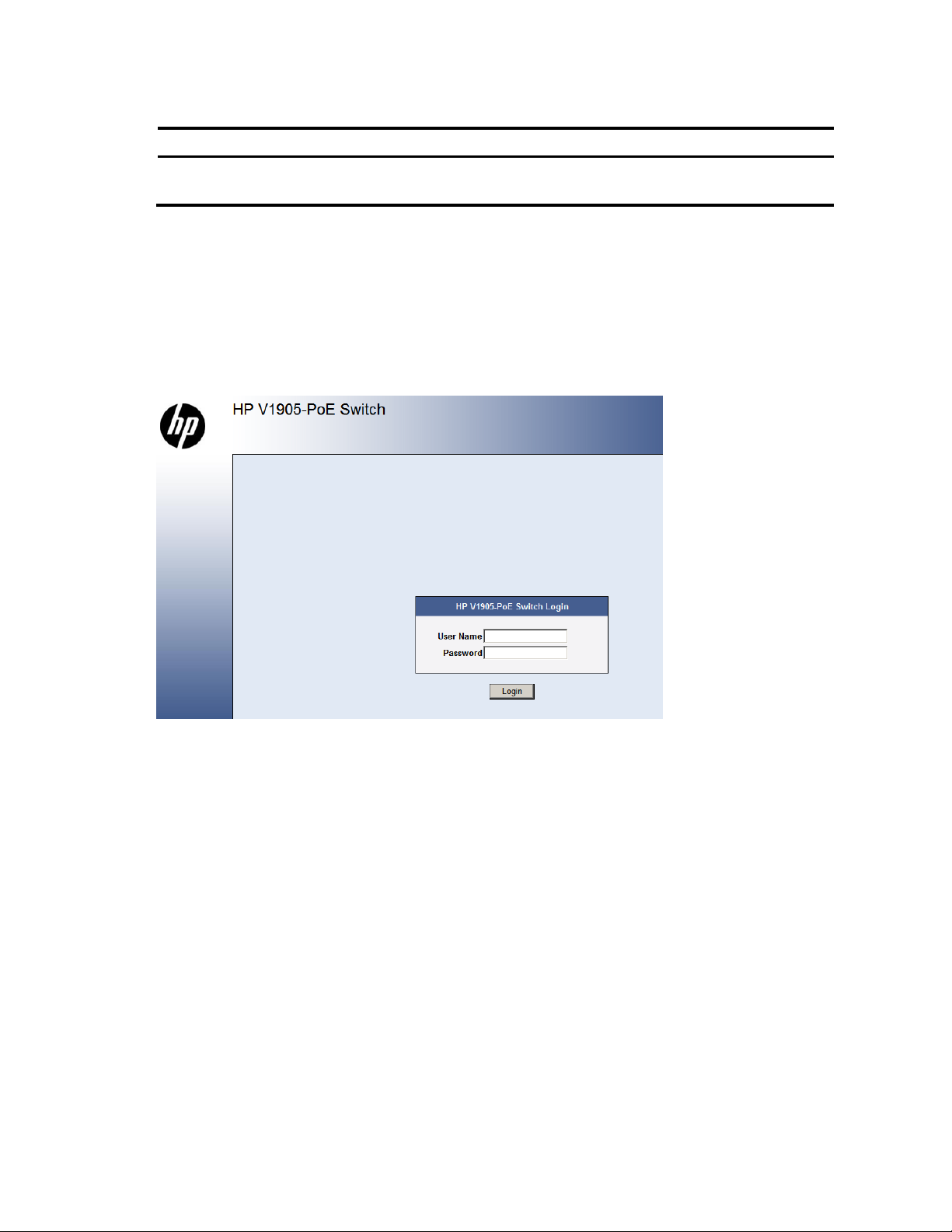
Logging On to the Web Interface
To log on to the Web interface, do the following:
1. Open your Web browser and enter the IP address of the switch that you wish to manage in the address
bar (For example, in the following format: http://xxx.xxx.xxx.xxx). The Login Page appears:
Figure 52 Login Page
2. Enter admin as your user name and leave the password field blank.
3. Click Login. The main Web interface page is displayed.
Navigating the Web Interface
The Web interface has been designed to enable you to easily perform advanced configuration tasks and
view information about the switch.
Menu
The menu is located on the left side of the Web interface. When you click an item on the menu, the related
screen appears in the main part of the interface. Some menu items will give you sub-menu tabs to choose
from.

14
Figure 53 Switch Screen Layout
Table 44 Available Menu Items
Menu Item Descri
p
tion
Device Summary
Contains tabs that allow you to:
Provide a summary of the switch’s basic settings and versions of
current components.
Display the description for each color coded port.
Save Configuration Saves the switch’s configuration
Administration
IP Setup
Allows you to setup, modify, or view the IP configuration
parameters.
ARP Setting
Allows a host to communicate with other hosts when only the IP
address of its neighbors is known.
Backup & Restore Allows you to backup and restore the switch’s configuration.
Firmware Upgrade Allows you to upgrade the current firmware via TFTP or HTTP
Reset Allows you to reset the switch to factory default settings
System Access
Contains tabs that allow you to:
Display user summary information.
Create a new user.
Modify existing users.
Remove existing users.
System Name Allows you to set the system name.
System Time Allows you to set the system time.
Logging
System Logs record and manage events and report errors and
informational messages
SNMP
Contains tabs that allow you to:
Add community strings.
Remove community strings.
Define SNMP traps
Remove SNMP traps

15
Menu Item Descri
p
tion
Device
VLAN
Contains tabs that allow you to:
Create a VLAN.
Modify a VLAN.
Modify VLAN membership for a port.
Rename a VLAN.
Remove a VLAN.
Display VLAN membership for a port.
Display VLAN information.
Spanning Tree
Allows you to configure a Spanning Tree Protocol.
Contains tabs that allow you to:
Display selected spanning tree information for every port.
Display individual port spanning tree information.
Modify the spanning tree settings for a port.
IGMP Snooping
Allows you to enable or disable IGMP snooping and IGMP query
modes.
Broadcast Storm Allows you to enable or disable broadcast control.
ACL Configures the ACL.
MAC Based ACL Configures MAC Based ACL on the switch.
IP Based ACL Configures IP Based ACL on the switch.
ACL Binding Configures ACL Binding on the switch.
QoS Configures QoS settings.
CoS
Contains tabs that allow you to:
Displays CoS default settings assigned to ports.
Defines CoS
Queue Configures Queue Setting.
CoS to Queue Displays and defines CoS to Queue.
DSCP to Queue Contains fields for mapping DSCP settings to traffic queues.
Trust Configures Trust Settings.
Bandwidth Displays and defines Bandwidth Settings.
VoIP Traffic Setting
Contains tabs that allow you to:
Display Voice VLAN summary.
Configure Voice VLAN global settings.
Configure Voice VLAN port settings.
Display port information for Voice VLAN.
Display OUI summary.
Add or remove OUI.
LLDP Allows you to configure LLDP global and port settings.

16
Menu Item Descri
p
tion
Port
Administration
Contains tabs that allow you to:
Display selected port information for the entire switch.
Display individual port information.
Modify the port settings.
Link Aggregation
Contains tabs that allow you to:
Display link aggregation summary.
Create an aggregation group.
Modify the port memberships.
Remove an aggregation group.
LACP Configures the LACP.
PoE(Only supported
by V1905-24-PoE
Switch)
Contains tabs that allow you to:
Display PoE summary.
Configure PoE settings.
Statistics Display statistics for a selected port.
Security
Radius Client
Contains tabs that allow you to:
Display Radius Client information.
Configure Radius Client settings and set authentication
parameters.
802.1X
Contains tabs that allow you to:
Display system authentication summary.
Display detailed information per port.
Configure system authentication settings.
LDB
Contains tabs that allow you to:
Configure LDB Parameters
Configure an Authentication Server
Configure a User Account
Monitoring
Address Table Displays MAC address table information for ports and VLANs.
Port Mirroring Monitor traffic going in or out of ports.
Cable Diagnostics
Contains tabs that allow you to:
Display selected cable diagnostics information for all ports.
Display all cable diagnostics information for a single port.
Help
Displays HP contact information and describes how to use the online
help system.
Logout Allows you to securely log off the Web interface.
Buttons
Depending on the screen that is currently displayed, the following buttons may appear:
Apply: Click to apply any changes that you have made.
Cancel: Click to discard any unsaved changes.

17
Select All: Allows the user to select all ports.
Select None: Removes the ports selected.
Help: Click to display the context-sensitive help information for the screen that is currently displayed.
The help pages provide information on the tasks that you can perform on each screen.
18
Configuring the Switch
Configuring System Access
Network administrators can define user name, password, and access level for users using the System
Access Interface. The Multi-Session Web feature is enabled on switch and allows 10 users to be created
and access the switch concurrently. Access levels provide read or read/write permissions to users for
configuring the switch. Login information is managed in the local database. A unique password is required
for each user. Two access levels exist on the Web Interface:
Management access level: Provides the user with read/write access rights. There is always one
management level user configured for the switch.
Monitor access level: Provides the user with read-only system access rights.
This section contains the following topics:
Defining System Access
Modifying System Access
Removing System Access
Viewing System Access Settings
CAUTION:
To ensure that unauthorized users do not access the Web interface, HP recommends that you set an admin
password when you first configure the switch.
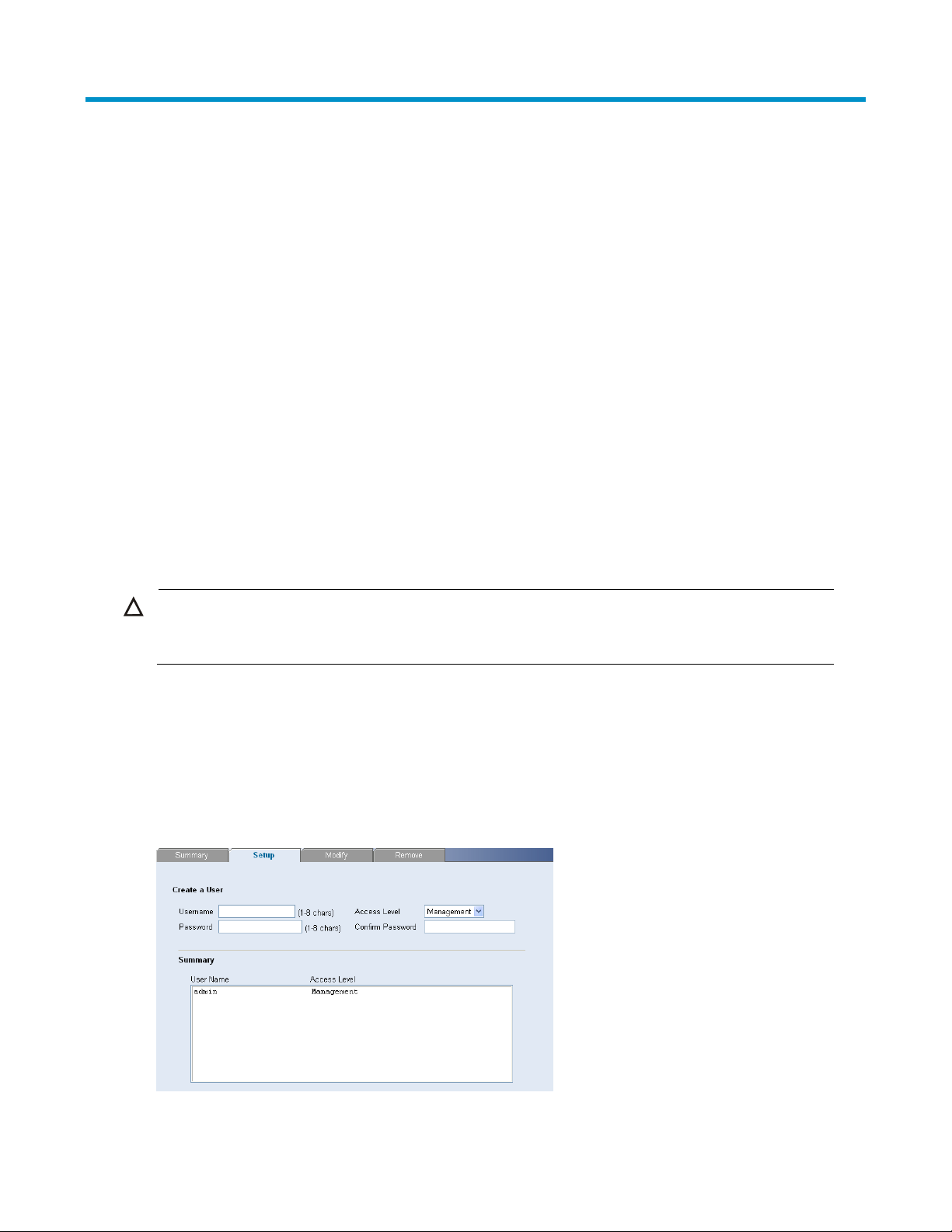
Defining System Access
The System Access Setup Page allows network administrators to define users, passwords, and access levels
for users using the System Access Interface.
Click Administration System Access Setup. The System Access Setup Page opens.
Figure 54 System Access Setup Page
19
The System Access Setup Page contains the following fields:
Table 45 System Access Setup Page item description
Item Descri
p
tion
User Name Defines the user name. The default value is admin.
Access Level
Defines the user access level. The lowest user access level is Monitor and the
highest is Management.
Management: Provides the user with read and write access rights. This is the
default.
Monitor: Provides the user with read access rights.
Password Defines the local user password. The default is blank.
Confirm Password Verifies the password.
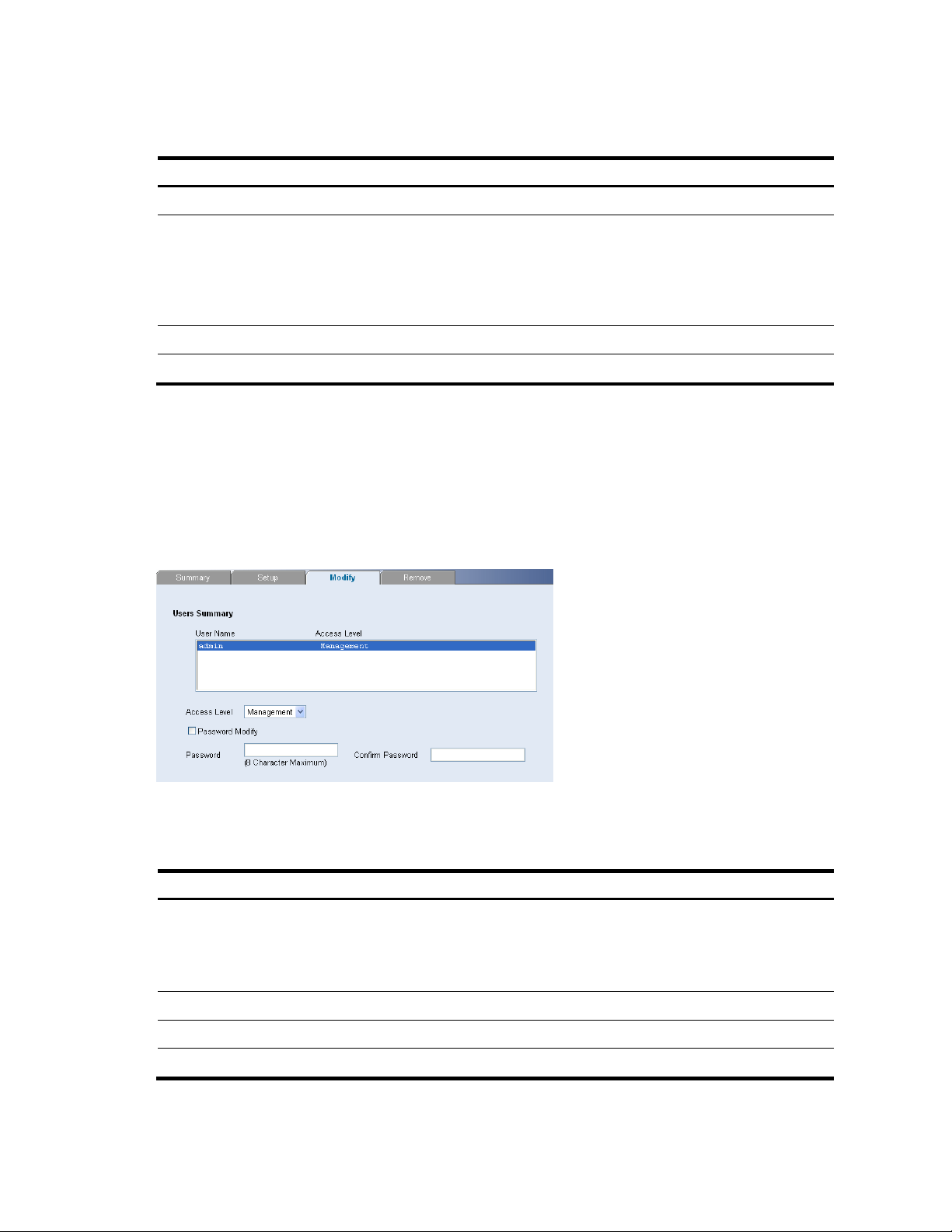
Modifying System Access
The System Access Modify Page allows network administrators to modify users, passwords, and access
levels for users using the System Access Interface.
Click Administration System Access Modify. The System Access Modify Page opens.
Figure 55 System Access Modify Page
The System Access Modify Page contains the following fields:
Table 46 System Access Modify Page item description
Item Descri
p
tion
Access Level
Defines the user access level. The lowest user access level is Monitor and the
highest is Management.
Management: Provides the user with read and write access rights.
Monitor: Provides the user with read access rights.
Password Modify Enables modifying a password for an existing user.
Password Modifies the local user password.
Confirm Password Verifies the password.
20
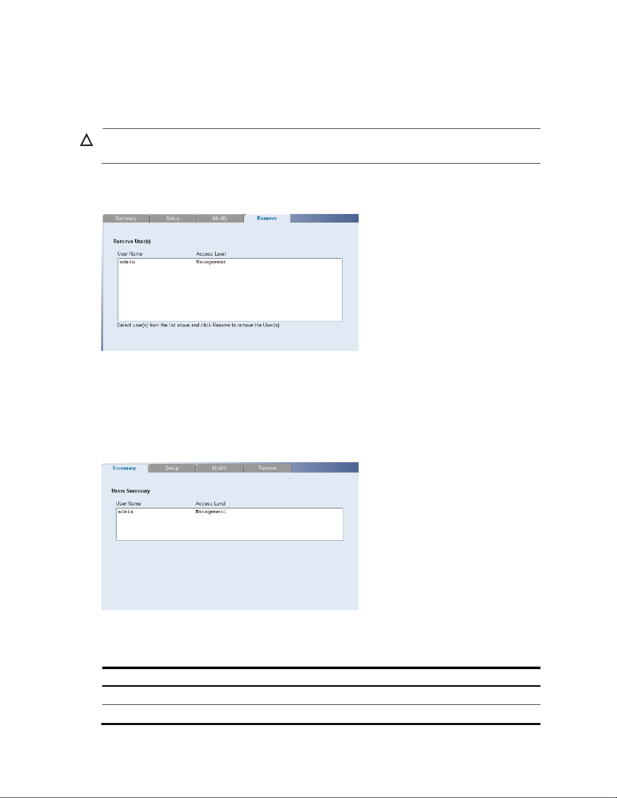
Removing System Access
The System Access Remove Page allows network administrators to remove users from the System Access
Interface.
CAUTION:
The last user with management access may not be deleted.
Click Administration System Access Remove. The System Access Remove Page opens.
Figure 56 System Access Remove Page
Viewing System Access Settings
The System Access Summary Page displays the current users and access levels defined on the switch.
Click Administration System Access Summary. The System Access Summary Page opens.
Figure 57 System Access Summary Page
The System Access Summary Page contains the following fields:
Table 47 System Access Summary Page item description
Item Descri
p
tion
User Name Displays the user name.
Access Level Displays the user access level.
21
Configuring IP and MAC Address Information
This section contains information for defining IP interfaces, and includes the following sections:
Defining IP Address
Configuring ARP Settings
Configuring MAC Address Table
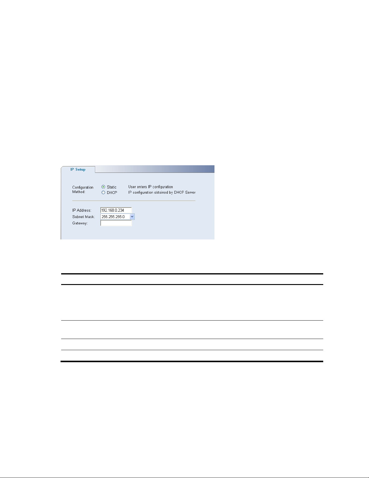
Defining IP Address
To enable the other devices on the network to communicate with the switch, you need to assign an IP
address to it: either by DHCP or by assigning a static IP address.
Click Administration IP Setup. The IP Setup Page opens.
Figure 58 IP Setup Page
The IP Setup Page contains the following fields:
Table 48 IP Setup Page item description
Item Descri
p
tion
Configuration Method
Defines whether the IP address is configured statically or dynamically. The
possible field values are:
Static: Specifies that the IP address is configured by the user.
DHCP: Specifies that the IP address is dynamically obtained by DHCP Server.
IP Address
Defines the IP address. The default value is 169.254.xxx.xxx. If the MAC address
is 08004E000102, the IP address would be 169.254.1.2.
Subnet Mask Defines the subnet mask. The default value is 255.255.0.0.
Gateway Defines the gateway address. The default value is blank.
Configuring ARP Settings
The Address Resolution Protocol (ARP) converts IP addresses into physical addresses, and maps the IP
address to a MAC address. ARP allows a host to communicate with other hosts when only the IP addresses
of its neighbors are known.
This section includes the following topics:
Defining ARP Settings

22
Removing ARP Entries
Viewing ARP Settings
Defining ARP Settings
The ARP Settings Setup Page allows network managers to define ARP parameters for specific interfaces.
Click Administration ARP Settings Setup. The ARP Settings Setup Page opens.
Figure 59 ARP Settings Setup Page
The ARP Settings Setup Page contains the following fields:
Table 49 ARP Settings Setup Page item description
Item Descri
p
tion
Interface Indicates the management VLAN (VLAN 1) for which ARP parameters are defined.
IP Address Defines the static IP address, which is associated with the static MAC address.
MAC Address Defines the static MAC address, which is associated with the static IP address.
ARP Entry Age Out
Specifies the aging time for dynamic ARP entries. After the ARP Entry Age,
dynamic ARP entries are deleted from the table. The range is 1-40000000. The
default value is 1200 seconds.
Removing ARP Entries
The ARP Entries Remove Page provides parameters for removing ARP entries from the ARP Table.
Click Administration ARP Settings Remove. The ARP Entries Remove Page opens.

23
Figure 60 ARP Entries Remove Page
The ARP Entries Remove Page contains the following fields:
Table 50 ARP Entries Remove Page item description
Item Descri
p
tion
Clear ARP Table Entries
Specifies the types of ARP entries that are cleared. The possible values are:
None: Maintains the ARP entries.
All: Clears all ARP entries.
Dynamic: Clears only dynamic ARP entries.
Static: Clears only static ARP entries.
Interface Indicates the VLAN for which ARP parameters are defined.
IP Address Indicates the IP address which is associated with the MAC address.
MAC Address
Displays the MAC address, which is associated in the ARP table with the IP
address.
Status
Displays the ARP table entry type. Possible field values are:
Dynamic: Indicates the ARP entry is learned dynamically.
Static: Indicates the ARP entry is a static entry.
Viewing ARP Settings
The ARP Settings Summary Page displays the current ARP settings.
Click Administration ARP Settings Summary. The ARP Settings Summary Page opens.

24
Figure 61 ARP Settings Summary Page
The ARP Settings Summary Page contains the following fields:
Table 51 ARP Settings Summary Page item description
Item Descri
p
tion
Interface Indicates the VLAN for which ARP parameters are defined.
IP Address Indicates the IP address, which is associated with the MAC Address.
MAC Address
Displays the station MAC address, which is associated in the ARP table with the IP
address.
Status
Displays the ARP table entry type. Possible field values are:
Dynamic: Indicates the ARP entry is learned dynamically.
Static: Indicates the ARP entry is a static entry.
Configuring MAC Address Table
MAC addresses are stored in either the static address or the dynamic address databases. A packet
addressed to a destination stored in one of the databases is forwarded immediately to the port.
The Dynamic Address Table can be sorted by interface, VLAN, and MAC address. MAC addresses are
dynamically learned as packets from sources arrive at the switch. MAC addresses are associated with ports
by learning the ports from the frames source address. Frames addressed to a destination MAC address that
is not associated with any port are flooded to all ports of the relevant VLAN.
Static addresses are manually configured. In order to prevent the bridging table from overflowing, dynamic
MAC addresses, from which no traffic is seen for a certain period, are erased.
This section includes the following sections:
Adding MAC Addresses to the Address Table
Defining Aging Time
Removing MAC Addresses for the specific port
Removing MAC Addresses from the Address Table
Viewing Address Table Settings
Viewing Port Summary Settings

25
Adding MAC Addresses to the Address Table
The Address Table Add Page allows the network manager to assign MAC addresses to ports with VLANs.
Click Monitoring Address Table Add. The Address Table Add Page opens.
Figure 62 Address Table Add Page
The Address Table Add Page contains the following fields:
Table 52 Address Table Add Page item description
Item Descri
p
tion
VLAN ID Selects a VLAN ID.
MAC Address Defines a MAC address to be assigned to the specific port and VLAN ID.
No Aging
Marks the aging status of the MAC address assigned by the user. The possible values
are:
Checked: Indicates that the Address Table entry assigned by the user is not aged
out.
Unchecked: Indicates that the Address Table entry assigned by the user is aged
out.
Defining Aging Time
The Address Table Aging Time Setup Page allows the network manager to define the Address Table Aging
Time. The Aging Time is the amount of time the MAC addresses remain in the Dynamic Address table before
they are timed out if no traffic from the source is detected. The default value is 300 seconds.
Click Monitoring Address Table Setup. The Address Table Aging Time Setup Page opens.
Figure 63 Address Table Aging Time Setup Page
 Loading...