Hitachi HTC426060G8CE00, HTC426040G8CE00, HTC426030G5CE00, HTC426020G5CE00 Quick Installation Guide

Quick Installation Guide
Hitachi Travelstar C4K60 Slim
Models: HTC426060G8CE00
HTC426040G8CE00
HTC426030G5CE00
HTC426020G5CE00
Handling precautions
ySet the drive down gently to prevent damage from impact or vibration.
yHandle the drive carefully by the edges. Do not touch the exposed printed circuit board or any electronic components.
yDo not press on the top or bottom of the drive.
yBefore handling the drive, discharge any static electricity from yourself and your clothing. With one hand touch an unpainted metal surface, then touch the ESD bag with the other hand. Remain in contact with the chassis and the bag for a minimum of two seconds.
yVibration, shock and static electricity to the drive will damage the precision parts. In particular, prevent vibration or shock generated by dropping, knocking over or hitting the drive. Also, avoid touching the electrical components directly, which can discharge electrostatic energy and damage the drive.
Page 1 |
version 1.0 |

Hitachi Global Storage Technologies
Mounting Recommendations
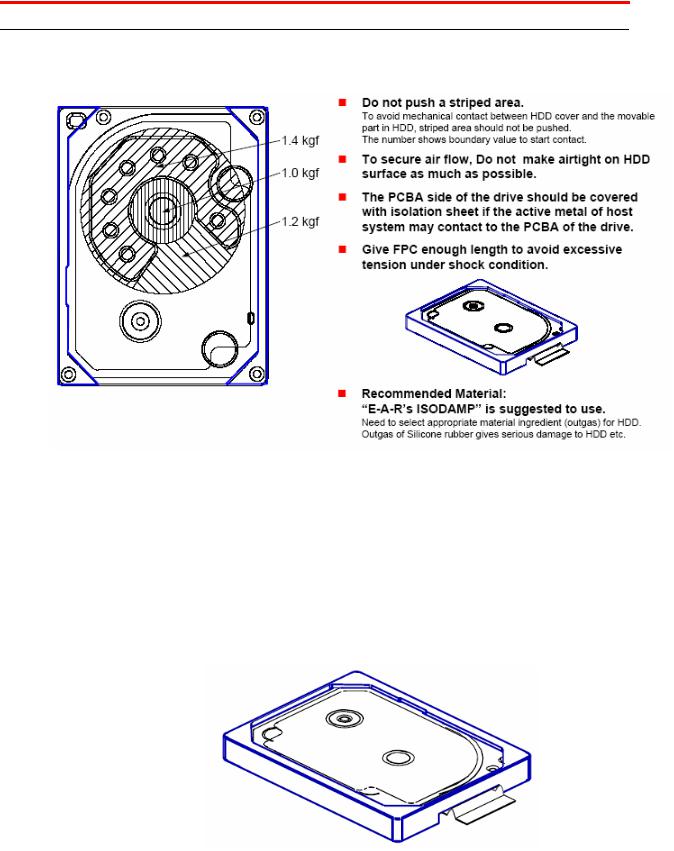
•There are no screw holes in the Travelstar C4K60 Slim hard disk drive. Hitachi recommends you secure the drive by placing it in a case as shown in the diagram below. Hitachi GST will assist customers with mounting design.
•The temperature of the center of the hard drive cover should remain less than 65°C at all times.
•The inertia of the chassis around the Z-axis of the gravity center of the device must be more than 3 x 10⁻⁴kg m2.
•In case of general Sub-notebook PC weight (1.7kg), the inertia of the chassis around the Z-axis of the gravity center of the device is greater than 100 x 10-4 kg m2. Therefore, the required inertia level does not conflict with the general electronic equipment.
•If installing the C4K60 next to a steel plate, the cover of the C4K60 and the steel plate must have at least 2mm of space between them. This is necessary for air flow and cooling requirements.
•The PCBA side of the drive should be covered with insulation if it is in contact with any metal part of the host system. Contact between the PCBA and metal may result in drive failure.
•The blue frame shown below represents the casing used when the drive can not be secured with screws.
Page 2 |
version 1.0 |
 Loading...