

Page 1

Technical Manual
TNC 426 CB/PB/M
TNC 430 CA/PA/M
NC Software 280 470-12
280 471-12
280 472-14
280 473-14
280 474-19
280 475-19
280 476-21
280 477-21
December 2001 343 734-21 · 10 · 12/2001 · Bi · Printed in Germany · Subject to change without notice
(343 734-E6)
Page 2

Foreword
This Technical Manual has been written for all machine tool manufacturers and
distributors. It contains all of the information necessary for the mounting,
electrical connection, commissioning and PLC programming of HEIDENHAIN
contouring controls.
Every time the hardware or software of HEIDENHAIN's contouring control is
updated, you will receive a set of supplementary pages free-of-charge. Always
sort these pages into your Technical Manual immediately. In this way, your
manual will always be up-to-date.
You can use extracts from this manual to supplement your machine
documentation. If you increase the size of the manual format (17 cm x 24 cm)
by the factor 1.225, you will have DIN A4 format.
No documentation is perfect. Documentation is alive. It thrives on your
comments and suggestions for improvement. Please help us by sending us
your ideas.
DR. JOHANNES HEIDENHAIN GmbH
E/P Department
Dr.-Johannes-Heidenhain-Str. 5
83301 Traunreut
Page 3

1 Update Information No. 6
1.1 Releases
The following NC software was released:
n NC software 280 474-18 and 280 475-18 June 2001
n NC software 280 474-19 and 280 475-19 August 2001
n NC software 280 476-15 and 280 477-15 November 2000
n NC software 280 476-16 and 280 477-16 December 2000
n NC software 280 476-17 and 280 477-17 March 2001
n NC software 280 476-18 and 280 477-18 April 2001
n NC software 280 476-19 and 280 477-19 July 2001
n NC software 280 476-20 and 280 477-20 August 2001
n NC software 280 476-21 and 280 476-21 November 2001
1.2 NC software 280 474-xx
NC software Setup Disks Release
280 474-18 286 195-21 06/2001
Export version:
280 475-18 286 195-21 06/2001
NC Software Setup Disks Release
280 474-19 286 195-22 08/2001
Export version:
280 475-19 286 195-22 08/2001
1.3 NC software 280 476-xx
NC software Setup Disks Release
280 476-15 286 197-17 11/2000
Export version:
280 477-15 286 197-17 11/2000
Machine parameters
Machine integration
n MP7441 has been expanded:
Bit 1: Reserved, enter 0
Bit 2: Error message “Enter depth as negative” when a positive depth was
programmed in the fixed cycles.
= 0: Error message is suppressed
= 1: Error message is not suppressed
n MP7682 has been expanded:
Bit 3: Reserved, enter 0
Bit 4: Reserved, enter 0
n Before a probing block, the control checks whether M4501 is set. If it is, the
probing block start is delayed by 1 second.
December 2001 Update Information No. 6 1 – 1
Page 4

NC software Setup Disks Release
280 476-16 286 197-18 12/2000
Export version:
280 477-16 286 197-18 12/2000
Machine parameters
PLC programming n FN18: SYSREAD has been expanded:
Machine parameters
n MP2221 has been expanded:
All HEIDENHAIN inverters except the UE 2xx compact inverter provide the
error signal ERR-IZ
Bit 2 = 0: Do not monitor the ERR-IZ
this signal (SIEMENS and INDRAMAT inverters, and HEIDENHAIN UE 2xx
compact inverters).
Bit 2 = 1: Monitor the ERR-IZ
compact inverters).
n The minimum input value of MP7430 was changed from 0.1 to 0.001.
You can ascertain the angle of misalignment between the spindle and the
tilted coordinate system.
ID210
NR8
n FN18: SYSREAD has been expanded:
You can find the measurement results of touch probe cycles 0 and 1 without
probe radius and length compensation.
ID360
NR3
NC Software Setup Disks Release
280 476-17 286 197-19 03/2001
Export version:
280 477-17 286 197-19 03/2001
n The PLC can change machine parameter MP2397.x.
n MP7683 has been expanded:
Bit 7: AUTOSTART function of an NC program through the PLC
0: AUTOSTART function of an NC program is performed by the NC.
1: AUTOSTART function of an NC program is performed by the PLC.
The NC does not trigger an NC start.
.
signal (HEIDENHAIN inverters except UE 2xx
signal, or the inverter doesn't supply
Machine integration
1 – 2 HEIDENHAIN Technical Manual TNC 426, TNC 430
n M4182 is new:
The marker indicates whether the autostart function was activated.
n M4183 is new:
The marker indicates whether the time from the autostart function has
expired.
n If an NC program block is interrupted in Single block mode or by a STOP
block and the positions of NC axes are changed, the NC program can be
restarted at the changed positions. If STRICTREPOS = YES in OEM.SYS, the
function for restoring the position is activated.
Page 5

Miscellaneous n When the control starts, it checks whether there is enough space on the
hard disk for system files. If not, the error message Too many setup files
appears. In this event, delete any unnecessary NC software or setup files
from the hard disk.
n When the control starts, the data of the fixed cycles and touch probe cycles
are checked and the resulting information is saved in the log.
NC software Setup Disks Release
280 476-17 286 197-20 03/2001
Export version:
280 477-17 286 197-20 03/2001
NC Software Setup Disks Release
280 476-18 286 197-21 04/2001
Export version:
280 477-18 286 197-21 04/2001
Machine parameters
Machine integration
n The maximum input values of MP1060.x and MP1070.x were extended to
30 [m/s
2
or 1000°/s2].
n MP7682 has been expanded:
Bit 4: Tolerance of rotary axes with M128
= 0: With consideration of head dimensions
= 1: Without consideration of head dimensions
n Since no speed encoder is used during volts-per-hertz (U/f) control mode,
W322 = 0. Module 9164 supplies the actual speed value while the spindle
is active, and not during the acceleration and braking phase.
NC Software Setup Disks Release
280 476-18 286 197-22 05/2001
Export version:
280 477-18 286 197-22 05/2001
NC Software Setup Disks Release
280 476-18 286 197-23 05/2001
Export version:
280 477-18 286 197-23 05/2001
NC Software Setup Disks Release
280 476-19 286 197-24 07/2001
Export version:
280 477-19 286 197-24 07/2001
Machine parameters
n MP2180 has been expanded, MP2181 has been added:
MP2180 has been expanded into MP2180.0 to MP2180.8.
In MP2180.0 to MP2180.8 and in MP2181, the same value must be entered.
n The maximum input value of MP2600.x was increased to
30 000 [A/(rev/s2)].
n MP7160 has been expanded:
Bit 3 = 0: IPC and acceleration feedforward control active
Bit 3 = 1: IPC and acceleration feedforward control not active
December 2001 Update Information No. 6 1 – 3
Page 6

Machine integration
PLC modules Module 9120 Starting a PLC axis
n If you save the actual position value with Module 9146 and then close the
position control loop, or if the position control loop is closed and the actual
position value is then saved with Module 9146, the error message Actual
position value saved <Axis> appears. The error message triggers an
emergency stop.
n A maximum of 16 variables can be used in the MP7530 column and in the
TEMPCOMP column of the description tables for the swivel axis geometry.
Module 9120 was expanded by an error code:
6= Feed rate not permitted
Module 9123 Traversing the reference marks of PLC axes
Module 9123 was expanded by an error code:
6= Feed rate not permitted
Miscellaneous n If REMOTE.PLCPASSWORDFORCED = YES in OEM.SYS, machine backup, full
Machine parameters
Machine integration
backup and setup are only possible with the code word defined in
PLCPASSWORD =.
NC Software Setup Disks Release
280 476-20 286 197-25 08/2001
Export version:
280 477-20 286 197-25 08/2001
NC Software Setup Disks Release
280 476-20 286 197-26 09/2001
Export version:
280 477-20 286 197-26 09/2001
NC software Setup disks Release
280 476-21 286 197-27 11/2001
Export version:
280 477-21 286 197-27 11/2001
n MP1152 is new:
0: I3 (control-is-ready signal acknowledgement) is passed on directly to
the NC
1: I3 is processed by the PLC before being passed on to the NC
n The machining plane position indication (MP7500 bit 1 = 1) has been
expanded by the following swivel-axis combination:
Swivel head and rotary table: axis sequence B variable, A variable (tool
axis Z)
n An internal EMERGENCY STOP can be simulated with the code number
FAILTEST in order to check the wiring of the machine. The control-is-ready
output is reset. The NC and PLC are no longer operable.
Danger
Hanging axes must be supported before the test in order to prevent
damage to the machine in case of error.
1 – 4 HEIDENHAIN Technical Manual TNC 426, TNC 430
Page 7

n The power module table was expanded by the following columns: I-N-DC,
T-DC, F-DC, T-AC, F-AC, T-IGBT, I-N-AC-3333, I-N-AC-4000, I-N-AC-5000,
I-N-AC-6666, I-N-AC-8000 and I-N-AC-10000. The columns currently have no
function.
n The motor table was expanded by the following columns T-DC, F-DC, T-AC
and F-AC. The columns currently have no function.
Miscellaneous n In the Machine-parameter programming mode, the DELETE ALL and SELECT
soft keys after the DEL/SEL SETUP soft key were switched.
1.4 Use of Speed Encoders with EnDat Interface
Regardless of the Type of encoder in the motor table, the control attempted
to communicate with a speed encoder with EnDat interface. If this did not
succeed, a speed encoder with Z1 track was assumed.
If an error occurred during communication with the EnDat encoder, the control
assumed that it was dealing with an encoder with a Z1 track. This was not the
case, however, since encoders with EnDat interface do not have a Z1 track.
This resulted in the error message C310 Z1 track error.
As of NC software 280 476-18 (in conjunction with the setup 286 197-22), the
control uses the Type of encoder entry in the motor table. If an encoder with
Z1 track is entered in the motor table, the message C310 Z1 track error
appears in the event of an error. If an encoder with EnDat interface is entered
in the motor table, the control attempts to communicate with the encoder. If
this fails, the error message C3F0 EnDat not found <axis> appears.
Warning
If you use the HEIDENHAIN standard motor table motor.mot and motors
with EnDat encoders, you might have to change the entry for the motor in
the SYS column (type of encoder) of the motor table or enter a new motor.
n SYS = 1: Incremental rotary encoder with Z1 track
n SYS = 2: Absolute speed encoder with EnDat interface
If you use the motor table motor.sn instead of motor.mot, the control
attempts to communicate with an encoder with EnDat interface. If this fails,
due to an error or because no EnDat encoder is connected, the control
assumes that it is dealing with an encoder with Z1 track and tries to read it. If
this fails, the error message C310 Z1 track error appears.
December 2001 Update Information No. 6 1 – 5
Page 8

1.5 Tool-Oriented Machining
As of NC software 280 476-17, “tool-oriented” pallet table machining is also
possible. For more information, please refer to the User's Manual.
A special tool-change macro is required for tool-oriented pallet machining. This
is defined through the keyword TCTOOLMODE= in NCMACRO.SYS.
This macro is called for tool oriented machining instead of the tool-change
macro. If this macro is not defined in NCMACRO.SYS, a HEIDENHAIN standard
macro is run.
The HEIDENHAIN standard macro performs the following functions:
n Positioning to clearance height
n Execution of M146
n Tool change through TOOL CALL. The existing tool-change macro is called.
The following new functions are available for interrogating whether a
clearance height was programmed in the pallet table:
n FN18: SYSREAD ID510 NR5 IDX(axis)
This function can ascertain whether a clearance height was programmed for
the corresponding axis.
n FN18: SYSREAD ID510 NR6 IDX(axis)
This function can ascertain the clearance height for the corresponding axis.
With the M function M146 the current geometry information is saved in a
temporary file.
An NC macro can be defined through the keyword CLAMP= in NCMACRO.SYS. The
macro is called when a loaded fixture (FIX) is called.
In addition to the standard prototype for pallet tables, the COPY SAMPLE
FILES soft key copies the prototype for tool-oriented pallet table machining
into the PLC:\PROTO directory. Both prototypes are offered when you create a
new pallet table. If you do not want this, delete a prototype from the
PLC:\PROTO directory. The existing prototype is then used automatically.
n Prototyp.P = standard prototype
n Proto_to.P = prototype for tool-oriented machining
1 – 6 HEIDENHAIN Technical Manual TNC 426, TNC 430
Page 9
1.6 Field Orientation
If a synchronous spindle is used along with an encoder without Z1 track or a
nonaligned encoder with EnDat interface, there is no assignment between the
encoder and rotor magnets. This is remedied by NC software 280 476-13 with
the new FIELD ORIENTATION function on the LE 426 M/30 000 rpm and the
LE 430 M. When put into service, the control automatically finds the
assignment between the encoder and the rotor magnets and saves this
information on the hard disk. From this time on the assignment is available to
the servo controller.
1.7 New Motor Table
As of NC software 280 476-13, the motor table motor.mot is used as the
standard table instead of the previous standard motor tables motor.asn and
motor.sn. Synchronous and asynchronous motors are registered in
motor.mot. If the new motor table motor.mot is not available, the control looks
for motor.asn and motor.sn.
You can transfer asynchronous motors from motor.asn into motor.mot. To
transfer synchronous motors into motor.mot, please contact HEIDENHAIN.
1.8 Hardware
New receiver units The EA 550 and EA 552 receiver units and the APE 511 interface electronics
for the connection of two EA 552 to the LE have been superseded by new
units.
LE 430 M/9 axes with flash EPROMs
Old units New units
EA 550 (Id. Nr. 262 904-xx) EA 632 (Id. Nr. 346 322-xx)
EA 552 (Id. Nr. 339 317-xx) EA 652 (Id. Nr. 346 323-xx)
APE 511 (Id. Nr. 275 759-xx) APE 652 (Id. Nr. 354 656-01)
On the LE 430/9 axes with flash EPROMs, only the speed encoder inputs and
the position encoder inputs X1 to X6 (but not X35 to X38) are equipped with
EnDat interface.
December 2001 Update Information No. 6 1 – 7
Page 10

1.9 Replacing Instructions
Page Change Remove
Page
Title New software December 2000 December 2001
Chapter 1 Update information – Update Info. 6
Chapter 2 Errors corrected, some descriptions
changed and updated
Chapter 3 Errors corrected, some descriptions
changed and updated
Chapter 4 Machine parameter list updated Entire chapter Entire chapter
Chapter 5 Module, marker and word lists updated Entire chapter Entire chapter
Chapter 6 Errors corrected, some descriptions
changed, updated and expanded
Chapter 7 Errors corrected, some descriptions
changed and updated
Chapter 8 Errors corrected, some descriptions
changed and updated, new descriptions
added
Chapter 9 No changes Entire chapter Entire chapter
Chapter 10 Errors corrected Entire chapter Entire chapter
Chapter 11 Index updated Entire chapter Entire chapter
Entire chapter Entire chapter
Entire chapter Entire chapter
Entire chapter Entire chapter
Entire chapter Entire chapter
Entire chapter Entire chapter
Insert
Page
1 – 8 HEIDENHAIN Technical Manual TNC 426, TNC 430
Page 11

2 Introduction
2.1 General Information ........................................................................ 2 – 3
2.2 Overview of Components ............................................................... 2 – 5
2.3 Brief Description ............................................................................ 2 – 22
2.4 Hardware ........................................................................................ 2 – 29
2.4.1 Designation of the Logic Unit .................................................. 2 – 29
2.5 Software ......................................................................................... 2 – 30
2.5.1 Designation of the Software ................................................... 2 – 30
2.5.2 Software Option ...................................................................... 2 – 32
2.5.3 PLC Software .......................................................................... 2 – 32
2.5.4 NC Software Exchange ........................................................... 2 – 33
2.5.5 Data Backup ............................................................................ 2 – 40
2.6 Software Releases ......................................................................... 2 – 42
2.6.1 NC Software 280 470-xx and 280 471-xx ................................ 2 – 42
2.6.2 NC Software 280 472-xx and 280 473-xx ................................ 2 – 45
2.6.3 NC Software 280 474-xx and 280 475-xx ................................ 2 – 52
2.6.4 NC Software 280 476-xx and 280 477-xx ................................ 2 – 61
December 2001 2 – 1
Page 12

2 – 2 HEIDENHAIN Technical Manual TNC 426, TNC 430
Page 13
2 Introduction
2.1 General Information
HEIDENHAIN contouring controls are designed for use with milling, drilling
and boring machines as well as machining centers.
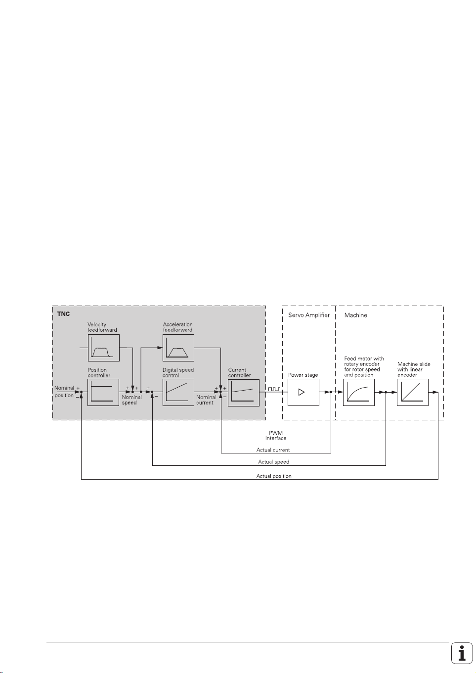
The TNC 426 PB/M, TNC 430 PA/M features integral digital drive control and
controls the power stages via PWM signals.
Integration of the drive controller in the TNC 426 PB/M, TNC 430 PA/M offers
the following advantages:
n All the software is contained centrally in the NC; this means that the
individual components of the NC such as feed axes, spindle, NC or PLC are
optimally matched.
n High control quality, because the position controller, speed controller and
current controller are combined into one unit.
n The same functions are available for commissioning, optimizing and
diagnosing feed drives as well as spindles.
With the TNC 426 PB, up to five axes and spindle speeds of up to
12 000 rpm can be controlled digitally (option: 30 000 rpm).
The TNC 430 PA supports up to 6 digitally controlled NC axes, 3 analog
controlled secondary axes, and digitally controlled spindle speeds up to
30 000 rpm.
December 2001 General Information 2 – 3
Page 14
The TNC 426 M offers digital control for up to 5 axes and spindle speeds up
to 12 000 rpm (option: 30 000 rpm). The TNC 430 M offers digital control for
up to six or nine axes and spindle speeds up to 30 000 rpm.
The TNC 426 M, TNC 430 M is designed for connection of a compact or
modular inverter system. Thus, together with HEIDENHAIN motors, a
complete control package including servo drive can be offered (see Technical
Manual “Inverter Systems and Motors”).
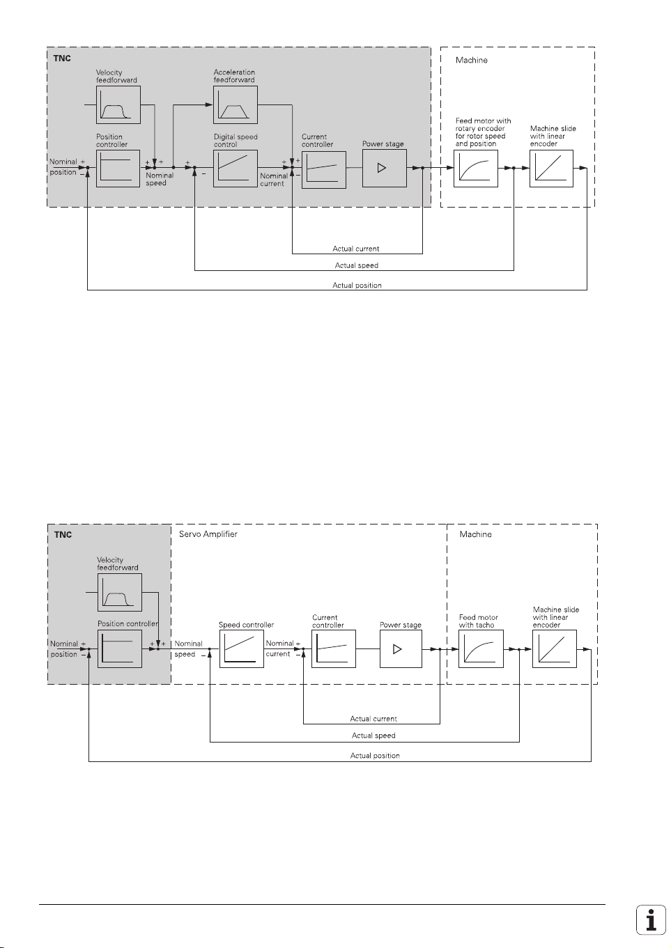
The TNC 426 CB is the version of the TNC 426 that is equipped with analog
speed command interface and can control machines with up to five axes plus
spindle. The TNC 430 CA also has an analog speed command interface for
machines with up to eight axes plus spindle. A ninth axis can be controlled
with an additional PCB.
2 – 4 HEIDENHAIN Technical Manual TNC 426, TNC 430
Page 15
2.2 Overview of Components
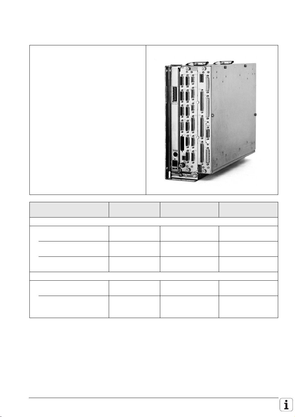
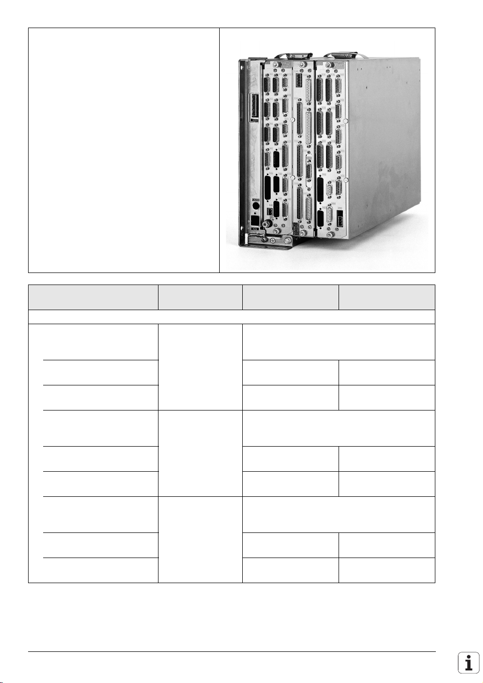
LE 426 CB, LE 430 CA Logic Unit
Logic unit Signal inputs ID numbers of LE for
BC 120 display unit
LE 426 CB
5 position inputs
1 spindle position input
5 position inputs
1 spindle position input
5 position inputs
1 spindle position input
1 V
(350 kHz)
PP
1VPP (350 kHz)
1 V
(50 kHz)
PP
(350 kHz)
1V
PP
11 µA
(50 kHz)
PP
1 VPP (350 kHz)
312 001-xx 313 524-xx
326 415-xx 326 419-xx
312 002-xx 313 525-xx
LE 430 CA
8 position inputs
1 spindle position input
5 position inputs
3 position inputs
1 spindle position input
1 V
(350 kHz)
PP
1VPP (350 kHz)
1 VPP (50 kHz)
1VPP (350 kHz)
1VPP (350 kHz)
311 050-xx 313 523-xx
326 418-xx 326 424-xx
ID numbers of LE for
BF 120 display unit
December 2001 Overview of Components 2 – 5
Page 16
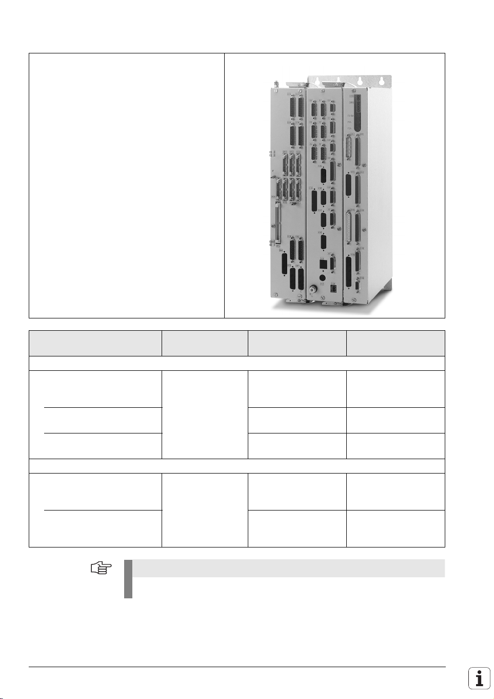
LE 426 PB, LE 430 PA Logic Unit
Logic unit Signal inputs ID numbers of LE for
BC 120 display unit
LE 426 PB
5 position inputs
1 spindle position input
6 speed inputs
Spindle
1 V
(350 kHz)
PP
1VPP (350 kHz)
1V
PP
312 000-xx 313 527-xx
up to 12 000 rpm
Spindle
315 475-xx 318 178-xx
up to 30 000 rpm
5 position inputs
1 spindle position input
6 speed inputs
Spindle
1 V
1V
1V
(50 kHz)
PP
(350 kHz)
PP
PP
326 414-xx 326 421-xx
up to 12 000 rpm
Spindle
326 416-xx 326 420-xx
up to 30 000 rpm
5 position inputs
1 spindle position input
6 speed inputs
Spindle
11 µAPP (50 kHz)
1VPP (350 kHz)
1V
PP
311 999-xx 313 526-xx
up to 12 000 rpm
Spindle
317 349-xx 318 177-xx
up to 30 000 rpm
ID numbers of LE for
BF 120 display unit
2 – 6 HEIDENHAIN Technical Manual TNC 426, TNC 430
Page 17

Logic unit Signal inputs ID numbers of LE for
BC 120 display unit
LE 430 PA
5 position inputs
1 spindle position input
7 speed inputs
5 position inputs
1 spindle position input
7 speed inputs
1 V
(350 kHz)
PP
1VPP (350 kHz)
1V
PP
1 VPP (50 kHz)
1VPP (350 kHz)
1V
PP
311 049-xx 313 521-xx
326 417-xx 325 716-xx
ID numbers of LE for
BF 120 display unit
December 2001 Overview of Components 2 – 7
Page 18
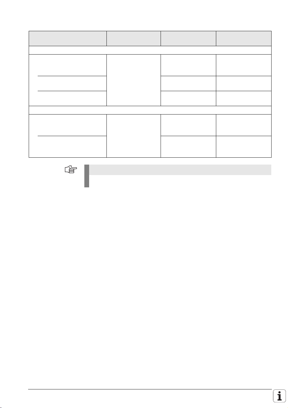
LE 426 M, LE 430 M Logic Unit
Logic unit Signal inputs ID numbers of LE for
BC 120 display unit
LE 426 M with EPROMs
6 position inputs
11 µA
PP
/1 VPP
(2 EnDats)
6 speed inputs
Spindle
1 V
PP
(2 EnDats)
324 990-xx 324 991-xx
up to 12 000 rpm
Spindle
324 994-xx 324 995-xx
up to 30 000 rpm
LE 430 M with EPROMs
6 position inputs
11 µA
PP
/1 VPP
324 992-xx 324 993-xx
(2 EnDats)
7 speed inputs
10 position inputs
10 speed inputs
(2 EnDats)
1 V
PP
11 µA
PP
/1 VPP
(6 EnDats)
(10 EnDats)
1 V
PP
324 996-xx 324 997-xx
Note
A BC 120 can also be attached to the LE for the BF 120 at the same time.
ID numbers of LE for
BF 120 display unit
2 – 8 HEIDENHAIN Technical Manual TNC 426, TNC 430
Page 19
Logic unit Signal inputs ID numbers of LE for
BC 120 display unit
LE 426 M with flash EPROMs
6 position inputs
11 µA
PP
/1 V
PP
(6 EnDats)
6 speed inputs
Spindle
1 V
/EnDat
PP
344 958-xx 344 959-xx
up to 12 000 rpm
Spindle
344 962-xx 344 963-xx
up to 30 000 rpm
LE 430 M with flash EPROMs
6 position inputs
11 µA
PP
/1 V
PP
344 960-xx 344 961-xx
(6 EnDats)
7 speed inputs
10 position inputs
10 speed inputs
1 VPP/EnDat
11 µAPP /1 V
(6 EnDats)
1 VPP/EnDat
PP
344 964-xx 344 965-xx
Note
A BC 120 can also be attached to the LE for the BF 120 at the same time.
ID numbers of LE for
BF 120 display unit
December 2001 Overview of Components 2 – 9
Page 20
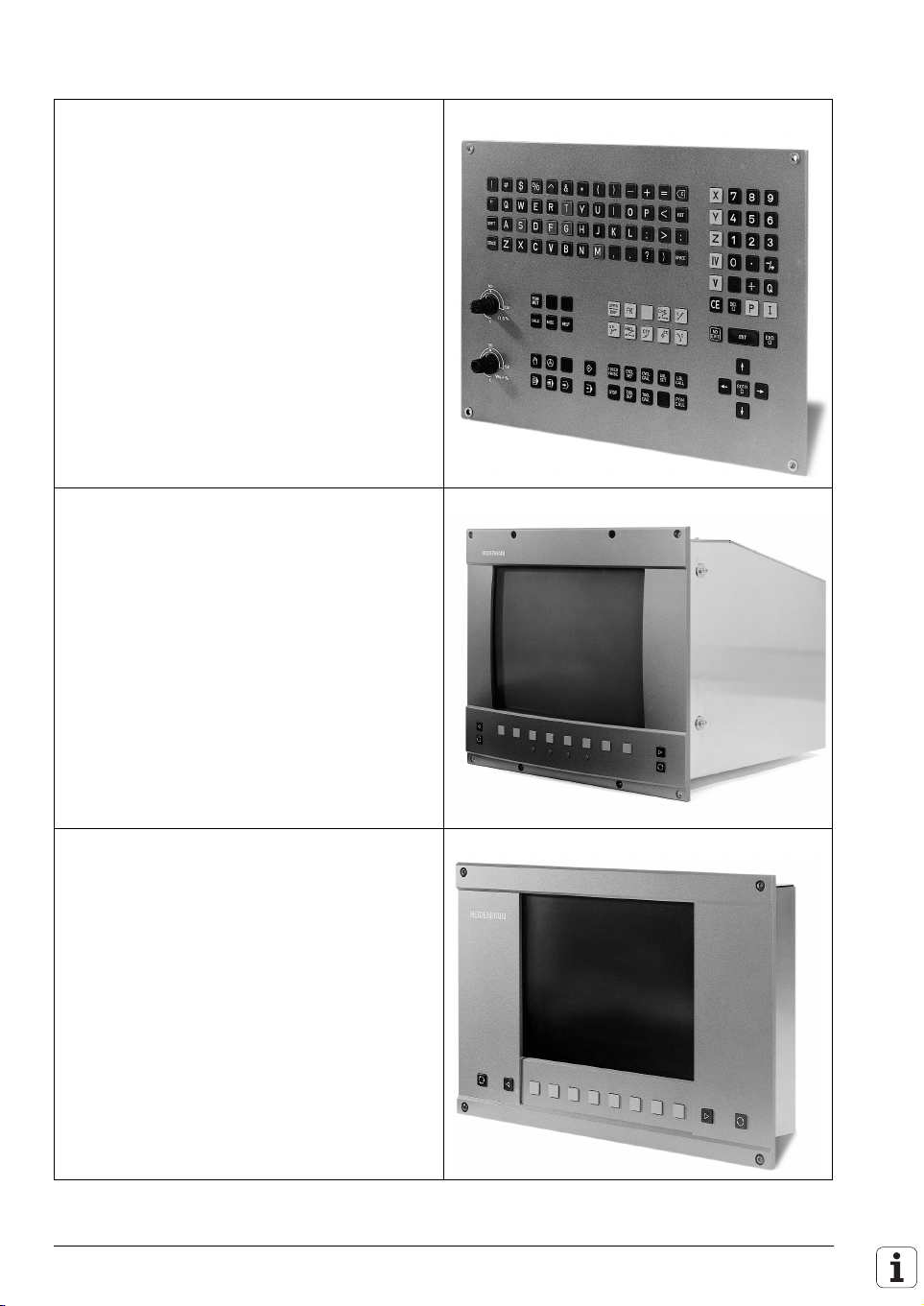
TE 420 Operating Panel
The IV and V keys are snap-ons, and can be
switched.
Id. Nr. 313 038-11
You can find an overview of the available key
symbols on Page 2 – 15.
Horizontal rows to match the design of the flatpanel display
Id. Nr. 316 343-01
BC 120 Visual Display Unit
15-inch color screen (640 x 480 pixels)
Id. Nr. 313 037-02
BF 120 Visual Display Unit
10.4-inch color flat panel display (640 x 480
pixels) Id. Nr. 313 506-02
2 – 10 HEIDENHAIN Technical Manual TNC 426, TNC 430
Page 21
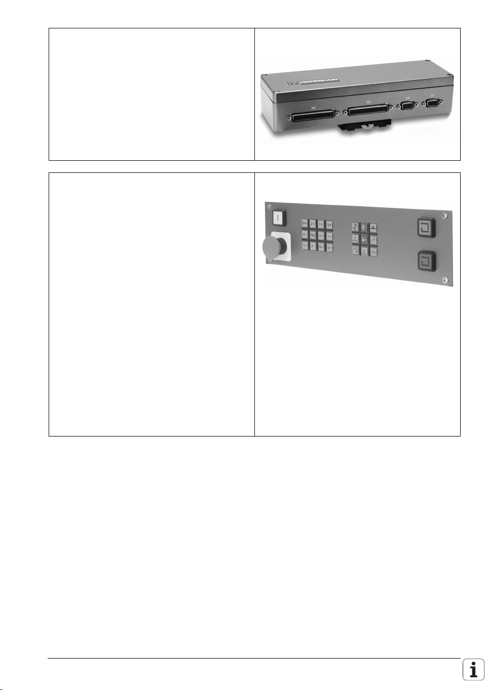
BTS 1x0 Monitor/Keyboard Switch
With the BTS 1x0, it is possible to connect two
monitors and two operating panels to an LE.
Id. Nr. 317 292-01
Id. Nr. 329 965-02
MB 420 Machine Operating Panel
Machine operating panel with snap-on
(switchable) keys. You can find an overview of
the available key symbols on Page 2 – 15.
Key assignment:
n Emergency stop
n Machine control voltage
n NC start, NC stop
n Five axis keys
n Rapid traverse
n Coolant
n Spindle start, spindle stop
n 7 keys for machine functions
• Standard assignment: FN 1 to FN 5
• Assignment for HEIDENHAIN basic PLC
program: Retract axis, Tool change, Unlock
tool, Menu selection →, Unlock door,
Rinse water jet, Chip removal
Id. Nr. 293 757-33
Id. Nr. 293 757-45
BTS 110 (2 x BC 120)
(see figure at right)
BTS 120 (2 x BF 120)
Standard
Basic PLC program
December 2001 Overview of Components 2 – 11
Page 22
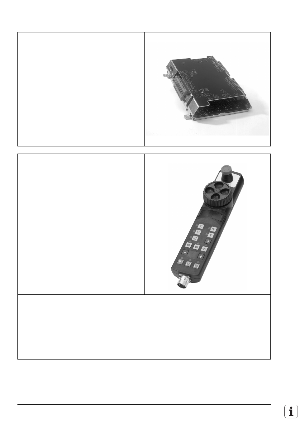
PL 410 B PLC Input/Output Unit
For the expansion of PLC inputs and outputs
Id. Nr. 263 371-12
64 inputs
31 outputs
Id. Nr. 263 371-02
PL 405 B PLC Input/Output Unit
Id. Nr. 263 371-22 32 inputs
HR 410 Handwheel
Portable handwheel with snap-on (switchable)
keys. You can find an overview of the available
key symbols on Page 2 – 15.
Assignment:
n Keys for selection of 5 axes
n Keys for traverse direction
n Keys for preset feeds
n Key for actual value position capture
n Three keys for machine functions (definable
with PLC)
• Spindle right, Spindle left, Spindle stop
• NC start, NC stop, Spindle start
(for HEIDENHAIN basic PLC program)
n Two permissive buttons
n Emergency stop
n Magnetic holding pads
Id. Nr. 296 469-44 HR 410 handwheel (Spindle right, Spindle left, Spindle stop)
Id. Nr. 296 469-45 HR 410 handwheel (NC start, NC stop, Spindle start)
64 inputs
31 outputs
4 analog inputs ± 10 V
4 inputs for
Pt 100
thermistors
15 outputs
Id. Nr. 312 879-01 Connecting cable for cable adapter (spiral cable 3 m)
Id. Nr. 296 467-xx Connecting cable for cable adapter (normal cable)
Id. Nr. 296 687-xx Connecting cable for cable adapter (metal armor)
Id. Nr. 296 466-xx Adapter cable to LE
Id. Nr. 281 429-xx Extension to adapter cable
Id. Nr. 271 958-03 Dummy plug for emergency-stop circuit
2 – 12 HEIDENHAIN Technical Manual TNC 426, TNC 430
Page 23

HR 130 Handwheel
Panel-mounted handwheel
Id. Nr. 254 040-05 With ergonomic control
knob, radial cable outlet
December 2001 Overview of Components 2 – 13
Page 24
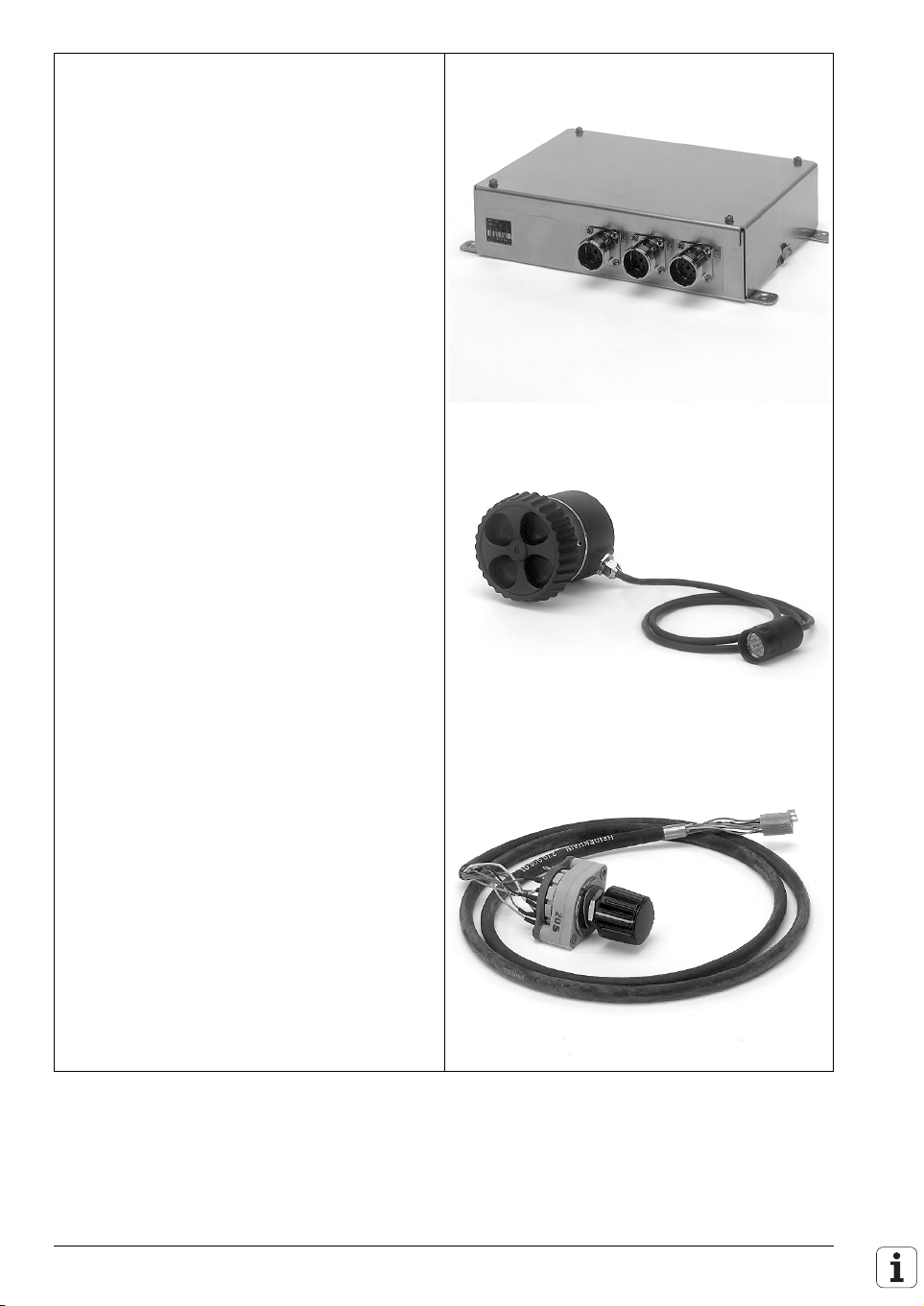
HRA 110 Handwheel Adapter
For connecting up to three HR 150 handwheels
with the TNC.
The axes and the subdivision factor are selected
via rotary switch.
Id. Nr. 261 097-03
HRA 110
Id. Nr. 257 061-09
Id. Nr. 270 908-01
HR 150, radial cable
outlet
Handwheel selection
switch
2 – 14 HEIDENHAIN Technical Manual TNC 426, TNC 430
Page 25
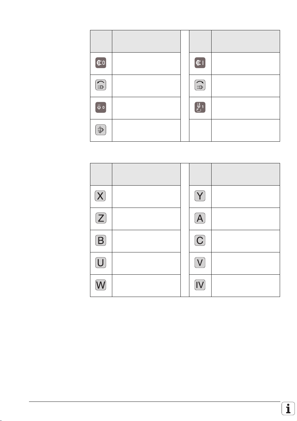
Key symbols for the spindle
Key Designation
Print/Background
Id. Nr.
Spindle stop
White/Red
330 816-08
Spindle direction left
Black/Gray
330 816-40
Spindle stop
White/Red
330 816-47
Clamp the axis
Black/Gray
330 816-48
Key symbols with axis designations
Key Designation
Print/Background
Id. Nr.
X
Black/Orange
330 816-24
Z
Black/Orange
330 816-25
B
Black/Orange
330 816-26
U
Black/Orange
330 816-43
W
Black/Orange
330 816-45
Key Designation
Print/Background
Id. Nr.
Spindle start
White/Green
330 816-09
Spindle direction right
Black/Gray
330 816-41
Spindle start
White/Green
330 816-46
Key Designation
Print/Background
Id. Nr.
Y
Black/Orange
330 816-36
A
Black/Orange
330 816-42
C
Black/Orange
330 816-23
V
Black/Orange
330 816-38
IV
Black/Orange
330 816-37
December 2001 Overview of Components 2 – 15
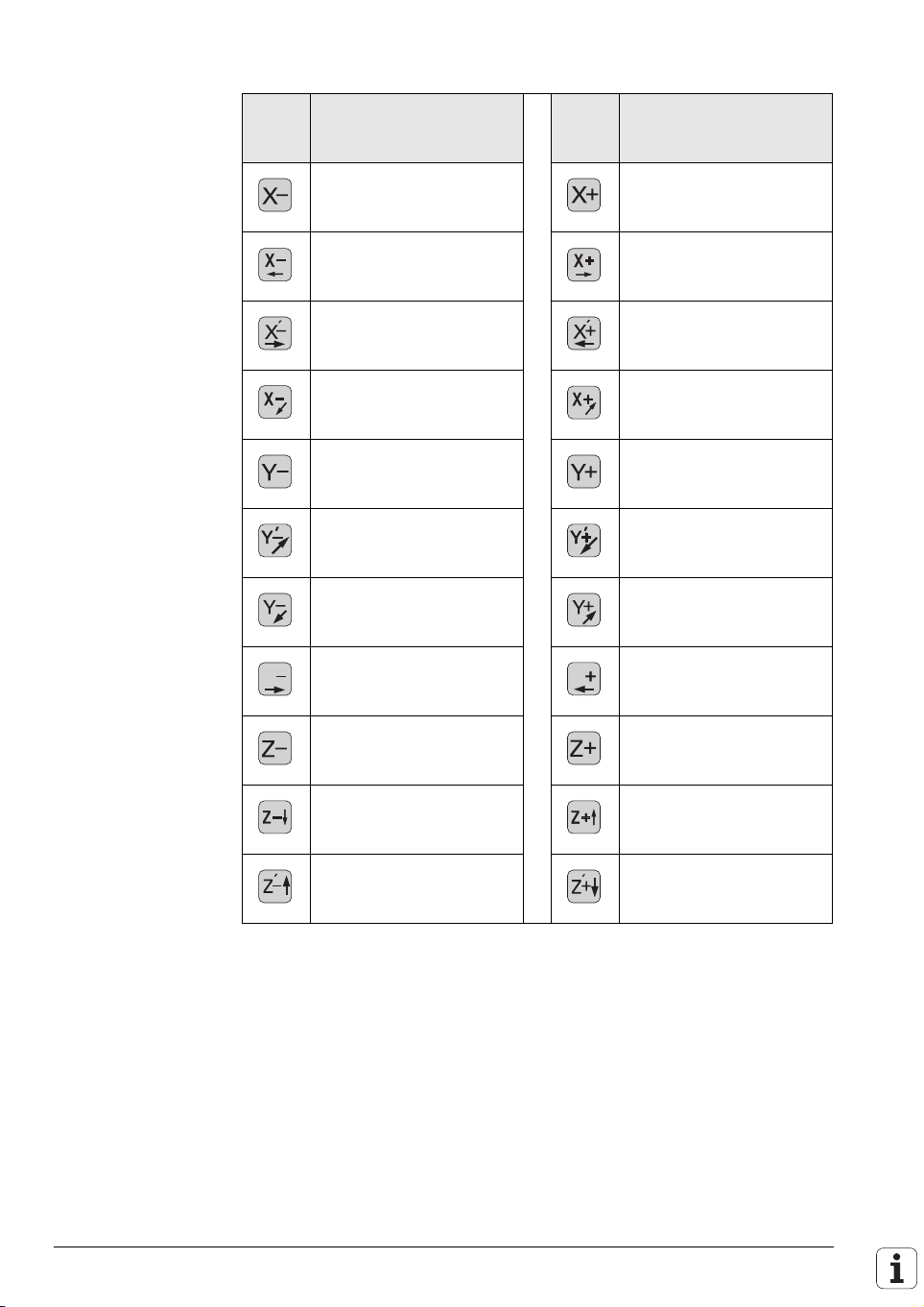
Page 26
Axis direction keys for the principle axes
Key Designation
Print/Background
Id. Nr.
X –
Black/Gray
330 816-63
X– <–
Black/Gray
330 816-18
X’– –>
Black/Gray
330 816-0W
X– <–
Black/Gray
330 816-0N
Y –
Black/Gray
330 816-67
Y’– –>
Black/Gray
330 816-21
Y– <–
Black/Gray
330 816-0P
Y– –>
Y
Black/Gray
330 816-0D
Z –
Black/Gray
330 816-65
Z– <–
Black/Gray
330 816-19
Z’– –>
Black/Gray
330 816-0L
Key Designation
Print/Background
Id. Nr.
X +
Black/Gray
330 816-64
X+ –>
Black/Gray
330 816-17
X’+ <–
Black/Gray
330 816-0V
X+ –>
Black/Gray
330 816-0M
Y +
Black/Gray
330 816-68
Y’+ <–
Black/Gray
330 816-20
Y+ –>
Black/Gray
330 816-0R
Y+ <–
Y
Black/Gray
330 816-0E
Z +
Black/Gray
330 816-66
Z+ –>
Black/Gray
330 816-16
Z’– <–
Black/Gray
330 816-0K
2 – 16 HEIDENHAIN Technical Manual TNC 426, TNC 430
Page 27
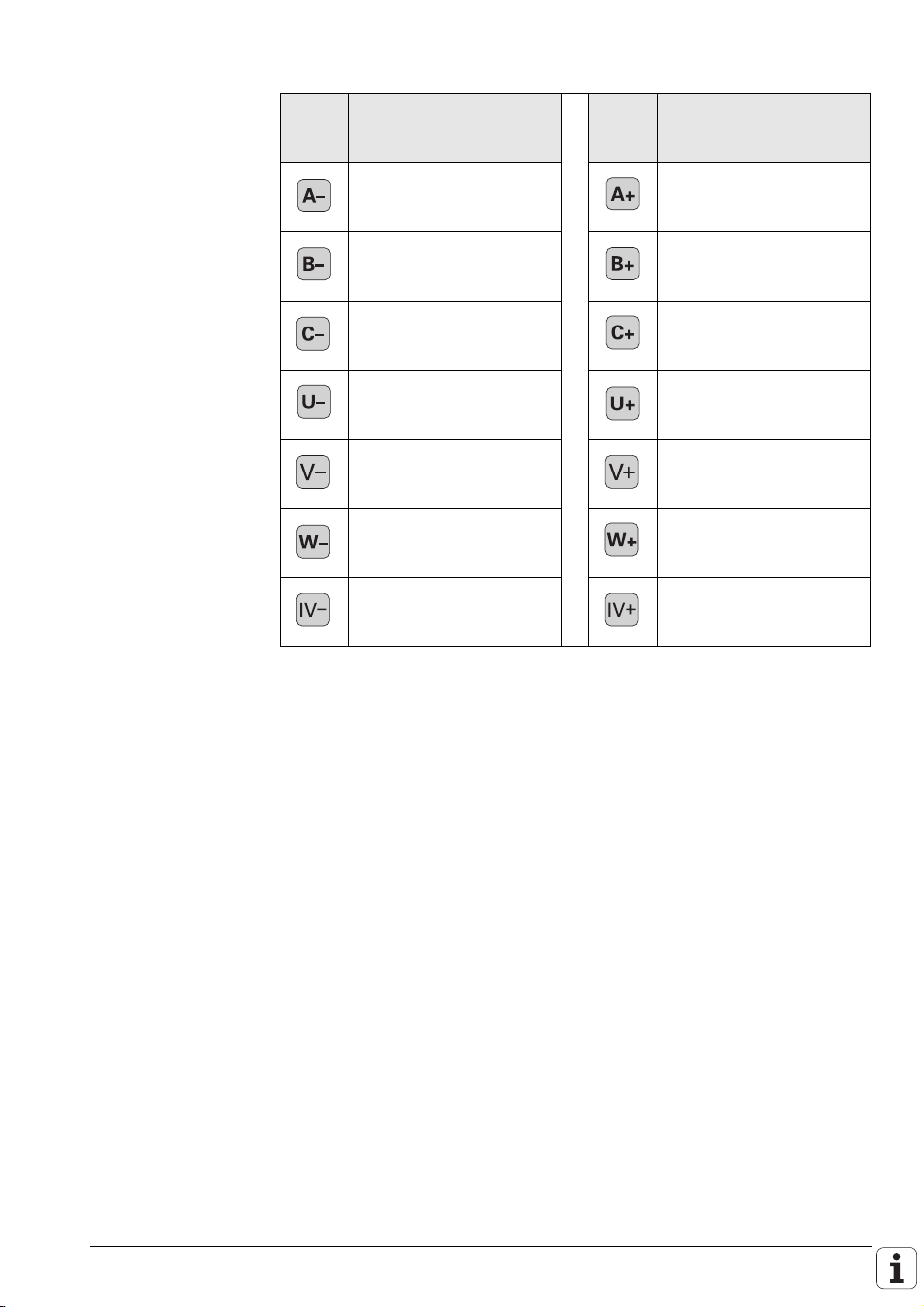
Key symbols for axis direction keys for rotary and secondary linear axes
Key Designation
Print/Background
Id. Nr.
A–
Black/Gray
330 816-95
B–
Black/Gray
330 816-97
C–
Black/Gray
330 816-99
U–
Black/Gray
330 816-0B
V–
Black/Gray
330 816-70
W–
Black/Gray
330 816-0G
IV–
Black/Gray
330 816-71
Key Designation
Print/Background
Id. Nr.
A+
Black/Gray
330 816-96
B+
Black/Gray
330 816-98
C+
Black/Gray
330 816-0A
U+
Black/Gray
330 816-0C
V+
Black/Gray
330 816-69
W+
Black/Gray
330 816-0H
IV+
Black/Gray
330 816-72
December 2001 Overview of Components 2 – 17
Page 28
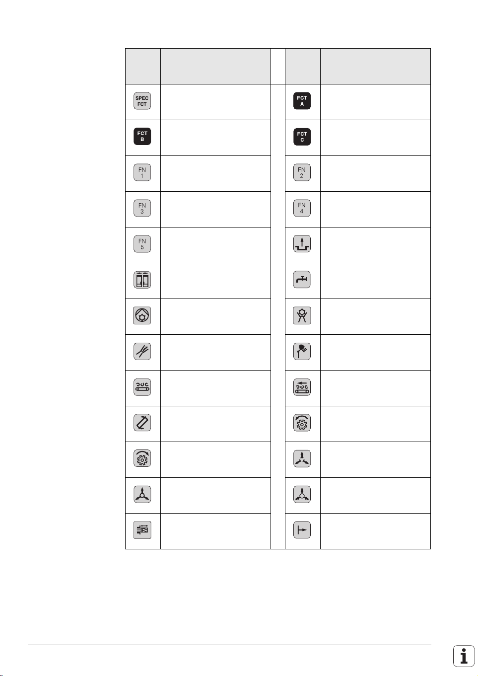
Key symbols for machine functions
Key Designation
Print/Background
Id. Nr.
Special function
Black/Gray
330 816-0X
Function B
White/Black
330 816-31
Function 1
Black/Gray
330 816-73
Function 3
Black/Gray
330 816-75
Function 5
Black/Gray
330 816-77
Unlock door
Black/Gray
330 816-79
Coolant (internal)
Black/Gray
330 816-0S
Rinse water jet
Black/Gray
330 816-81
Chip removal
Black/Gray
330 816-83
Tool change
Black/Gray
330 816-89
Tool changer right
Black/Gray
330 816-86
Unlock tool
Black/Gray
330 816-88
Lock tool
Black/Gray
330 816-0U
Key Designation
Print/Background
Id. Nr.
Function A
White/Black
330 816-30
Function C
White/Black
330 816-32
Function 2
Black/Gray
330 816-74
Function 4
Black/Gray
330 816-76
Unlock door
Black/Gray
330 816-78
Coolant
Black/Gray
330 816-80
Coolant (external)
Black/Gray
330 816-0T
Spotlight
Black/Gray
330 816-82
Chip conveyor
Black/Gray
330 816-84
Tool changer left
Black/Gray
330 816-85
Unlock tool
Black/Gray
330 816-87
Lock tool
Black/Gray
330 816-94
Retract axis
Black/Gray
330 816-91
2 – 18 HEIDENHAIN Technical Manual TNC 426, TNC 430
Page 29
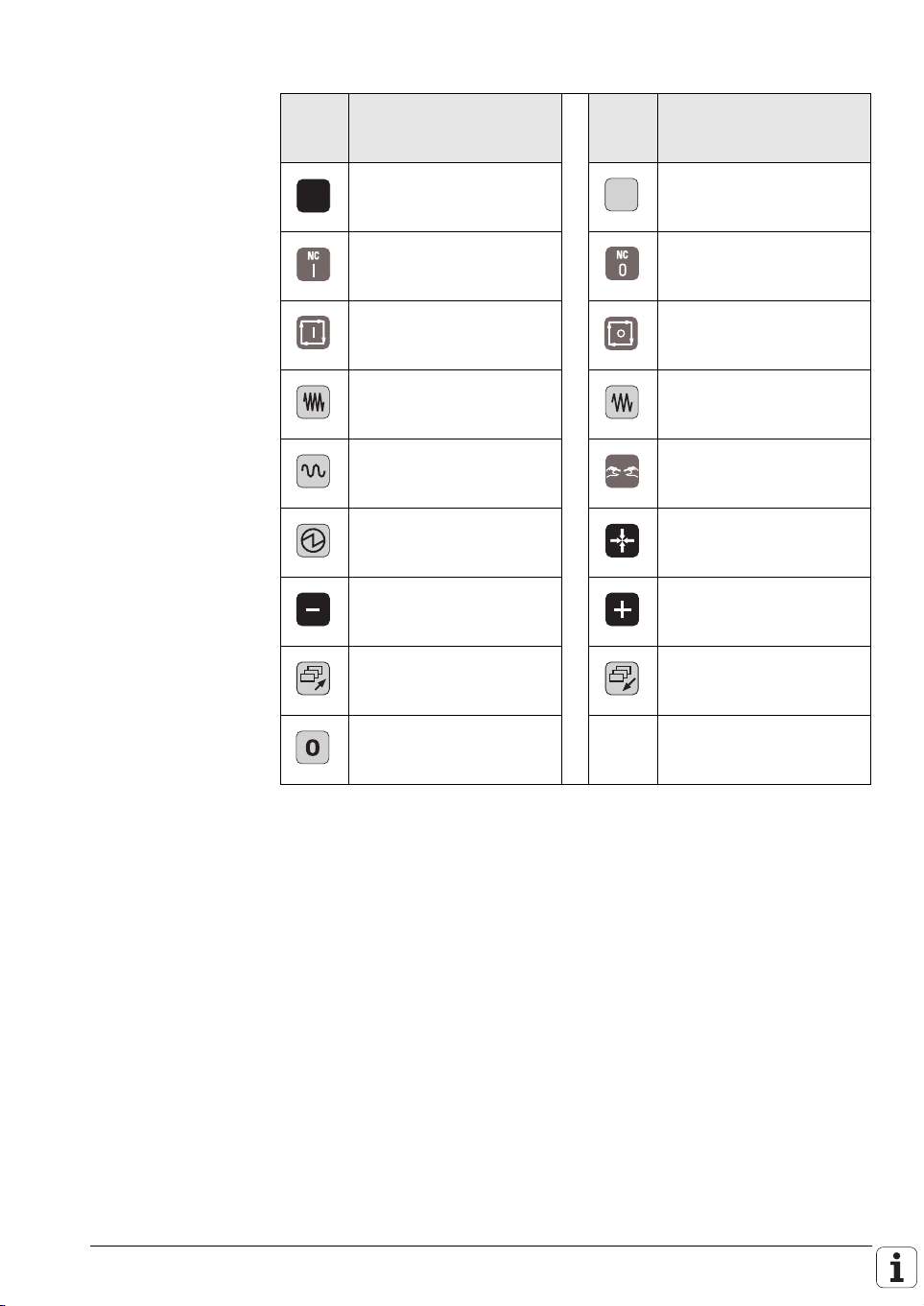
Other key symbols
Key Designation
Print/Background
Id. Nr.
No symbol
–/Black
330 816-01
NC start
White/Green
330 816-11
NC start
White/Green
330 816-49
Feed rate 1
Black/Gray
330 816-33
Rapid traverse
Black/Gray
330 816-35
Permissive key
Black/Gray
330 816-90
–
White/Black
330 816-28
Menu selection –>
Black/Gray
330 816-92
0
Black/Gray
330 816-0Y
Key Designation
Print/Background
Id. Nr.
No symbol
–/Gray
330 816-61
NC stop
White/Red
330 816-12
NC stop
White/Red
330 816-50
Feed rate 2
Black/Gray
330 816-34
Permissive key
White/Green
330 816-22
Actual position capture
White/Black
330 816-27
+
White/Black
330 816-29
Menu selection <–
Black/Gray
330 816-93
December 2001 Overview of Components 2 – 19
Page 30
TS 220 Touch Probe
Touch-trigger probe with cable connection for
workpiece setup, measurement during
machining, and digitizing.
Id. Nr. 293 488-xx
Id. Nr. 274 543-xx
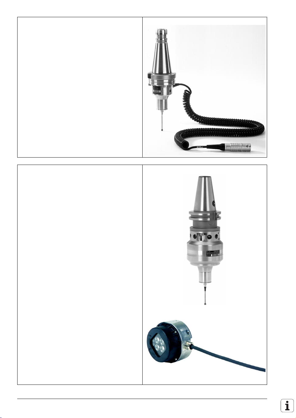
TS 632 Touch Probe
Touch-trigger probe with infrared transmission,
for workpiece setup and measurement during
machining.
Id. Nr. 331 397-xx
Id. Nr. 346 322-xx
Id. Nr. 346 323-xx
TS 220
Adapter cable for
connection to the LE
TS 632
EA 632 receiver unit
EA 652 receiver unit
Id. Nr. 354 656-xx
Id. Nr. 310 197-xx
2 – 20 HEIDENHAIN Technical Manual TNC 426, TNC 430
APE 652 interface
electronics for connecting
two EA 652 to the LE
Adapter cable for
connecting the EA 632 or
the APE 652 with the LE
Page 31

TT 130 Tool Touch Probe
Touch-trigger probe for measuring tools.
Id. Nr. 296 537-xx
TT 130
Id. Nr. 335 332-xx
Adapter cable for
connection to the LE
Further components Id. Nr.
Options for TNC 426 CB/PB, TNC 430 CA/PA
Additional position input for a 6th or 9th axis
311 537-51
(350 kHz)
Only TNC 430 PA:
294 130-51
Position input for 3 additional axes with nominal
speed command interface (350 kHz)
Ethernet interface 293 890-xx
Digitizing with triggering 3-D touch probe 286 405-01
Digitizing with a measuring 3-D touch probe
311 647-51
(SP 2/1)
Options for TNC 426 M, TNC 430 M
Ethernet interface 293 890-xx
Digitizing with triggering 3-D touch probe 286 405-01
Digitizing with a measuring 3-D touch probe
325 818-51
(SP 2/1)
Adapters for encoder signals
TTL (HEIDENHAIN layout)/1 V
TTL (SIEMENS layout)/1 V
11 µA
to LE 426 M, LE 430 M
PP
PP
PP
317 505-01
317 505-02
317 505-05
(as of xxx xxx-3x)
11 µA
PP
/1 V
PP
313 119-01
Documentation Items supplied with the control include:
n 1 User’s Manual for conversational programming
n 1 User’s Manual for ISO programming
n 1 Pilot (brief user’s programming guide)
The HEIDENHAIN inverters and motors for the TNC 426 M and the
TNC 430 M are described in the Technical Manual “Inverter Systems and
Motors.”
The components required for operating the TNC 426 and TNC 430 with nonHEIDENHAIN inverter systems are described in the “Technical Information for
Operation of SIMODRIVE and POWER DRIVE inverter systems.”
You will receive a set of supplementary pages every time changes are made
to this manual.
December 2001 Overview of Components 2 – 21
Page 32

2.3 Brief Description
Specifications TNC 426 TNC 430
Basic version with integrated motor control
TNC 426 PB, TNC 430 PA:
All position and speed inputs 1 V
TNC 426 M, TNC 430 M:
All position inputs 1 V
All speed inputs 1 VPP or EnDat
TNC 426 PB:
n 5 axes plus spindle (up to
12 000 rpm) with position
and speed inputs
n 5 axes plus spindle (up to
30 000 rpm) with position
and speed inputs
TNC 426 M:
n 5 axes plus spindle
(up to 12 000 rpm) with
position and speed inputs
n 5 axes plus spindle (up to
30 000 rpm) with position
and speed inputs
Basic version with analog speed command interface
Position inputs 1 V
TNC 426 CB:
n 5 axes plus spindle
Options
n Digitizing with triggering touch probe
n Digitizing with measuring touch probe
n Ethernet interface
PP
or EnDat
PP
PP
TNC 430 PA:
n 5 axes plus spindle (up to
30 000 rpm) with position
and speed inputs
n 6th axis with speed input
TNC 430 M:
n 6 axes plus spindle (up to
30 000 rpm) with 6
position and 7 speed
inputs
n 9 axes plus spindle (up to
30 000 rpm) with position
and speed inputs
TNC 430 CA:
n 8 axes plus spindle
TNC 430 CA:
n Position input for the
9th axis
TNC 430 PA:
n Position inputs for 3
additional axes with
analog speed interface
n Position input for the
6th axis
2 – 22 HEIDENHAIN Technical Manual TNC 426, TNC 430
Page 33

Specifications TNC 426 TNC 430
Display
n 15-inch CRT color screen
n 10.4-inch TFT color flat-panel display
Program memory
Hard disk with > 2 gigabytes
Input resolution and display step
Up to 0.1 µm for linear axes
Up to 0.0001° for angular axes
Interpolation
Straight lines 5 of 5 axes 5 of 9 axes
Circle n 2 of 5 axes
n 3 of 5 axes with tilted
working plane
Helices Superimposition of circular and linear paths
Interpolation
Spline Cubical splines can be executed
Block processing time
From the hard disk: 4 ms
n 2 of 9 axes
n 3 of 9 axes with tilted
working plane
December 2001 Brief Description 2 – 23
Page 34

Machine Integration TNC 426 TNC 430
Feedback control
Integral drive control TNC 426 PB, TNC 426 M TNC 430 PA, TNC 430 M
Analog speed command interface TNC 426 CB TNC 430 CA
Position loop resolution
Cycle time for path interpolation TNC 426 CB/PB, TNC 430 CA/PA: 3 ms
Cycle time for speed TNC 426 PB/M, TNC 430 PA/M: 0.6 ms
Nominal feed rate TNC 426 PB/M, TNC 430 PA/M:
Speed TNC 426 PB (Standard),
Signal period
----------------------------------------1024
TNC 426 M, TNC 430 M: can be set between 3 ms and
6ms
24000
----------------------------------------------------
No. of pole pairs
TNC 426 PB/M, TNC 430 PA/M:
n Up to 60 m/min for encoders with 20 µm grating period
n Up to 300 m/min for encoders with 100 µm grating
period
TNC 426 M/12 000 rpm:
24000
---------------------------------------------------No. of pole pairs
TNC 426 PB (option),
TNC 426 M/30 000 rpm:
60000
---------------------------------------------------No. of pole pairs
Volts-per-hertz control
mode
TNC 426 M/12 000 rpm:
24000
---------------------------------------------------No. of pole pairs
⋅⋅
srew pitch min
1–
⋅
min
TNC 430 PA,
TNC 430 M:
⋅
⋅
min
min
1–
1–
60000
---------------------------------------------------No. of pole pairs
Volts-per-hertz control
mode
TNC 430 M:
60000
---------------------------------------------------No. of pole pairs
1–
1–
min
⋅
1–
⋅
min
TNC 426 M/30 000 rpm:
60000
---------------------------------------------------No. of pole pairs
TNC 426 CB: TNC 430 CA:
100000 rpm 100000 rpm
Error compensation
n Linear and nonlinear axis error
n Backlash
n Reversal spikes during circular movements
n Offset
n Thermal expansion
n Stiction
n Sliding friction
2 – 24 HEIDENHAIN Technical Manual TNC 426, TNC 430
⋅
min
1–
Page 35

Machine Integration TNC 426 TNC 430
Integral PLC
PLC memory Hard disk
Main memory (RAM) 512 KB
PLC cycle time TNC 426 CB/PB, TNC 430 CA/PA: 21 ms
TNC 426 M, TNC 430 M: can be set between 21 ms and
120 ms
PLC inputs 24 Vdc 56 (additional inputs as option)
PLC outputs 24 Vdc 31 (additional outputs as option)
Analog inputs ±10 V 3 (additional analog inputs as option)
Analog outputs ±10 V TNC 426 PB/M: 13 TNC 430 PA/M: 13
TNC 430 CA: 3 with 9 NC
axes plus spindle
TNC 430 CB: 7 with 5 NC
axes plus spindle
Inputs for thermistors 3 (additional inputs as option)
Commissioning aids
n Oscilloscope
n Trace function
n Table function
n Logic diagram
n Log
Data Interfaces
n One each RS-232-C/V.24 and RS-422/V.11 with max.
115 Kbps
n Expanded data interface with LSV2 protocol for external
operation of the TNC
n Option: Ethernet interface approx. 200 kbps to 1 Mbps
December 2001 Brief Description 2 – 25
Page 36

User functions TNC 426 and TNC 430
Program entry HEIDENHAIN conversational and ISO
Position data n Nominal positions for straight lines and circles in Cartesian or
Contour approach and departure n Via straight line: tangential or perpendicular (APPR/DEP)
Tool compensation n Tool radius in the working plane, tool length
Cutting data table For automatic calculation of speed and feed rate from various
Constant contour speed n With respect to the path of the tool center
3-D machining n Reduced feed rate during plunging (M103)
Machining with rotary tables n Programming a contour on a cylindrical surface as if on a plane
FK free contour programming FK free contour programming in HEIDENHAIN conversational
Subprogramming Program section repeats, subprograms, program calls
Background programming Creating or editing a program while another program is being run
Fixed cycles n Peck drilling, tapping with or without a floating tap holder,
polar coordinates
n Absolute or incremental dimensional data
n Display and input in mm or inches
n Display of handwheel path during machining with handwheel
superpositioning
n Via circular arc (APPR/DEP)
n Via rounding radius (RND)
n Radius compensated contour look ahead for up to 99 blocks
(M120)
definable combinations of tool and workpiece materials
n With respect to the tool cutting edge (M109, M110, M111)
n 3-D tool compensation through surface normal vectors
n Automatic compensation of machine geometry when working
with tilted axes (M114, M115, M128, M129, M130)
n Changing the position of the swivel head with the electronic
handwheel during program run. The position of the tool tip does
not change.
n Jerk reduction
n Spline
n Tool perpendicular to contour
n Tool radius compensation perpendicular to traversing and tool
direction
n Feed rate in mm/min (M116)
format with graphic support for workpiece drawings not
dimensioned for NC
— also with graphical support
reaming, boring, hole patterns, slot milling, rectangular and
circular pocket milling, stud finishing, face milling of plane
surfaces
n OEM cycles (special cycles developed by the machine tool
builder) can also be integrated
n Contour pockets — also contour parallel
n Contour train
2 – 26 HEIDENHAIN Technical Manual TNC 426, TNC 430
Page 37

User functions TNC 426 and TNC 430
Coordinate transformation n Datum shift, rotation, mirroring
n Scaling factor (axis specific)
n Tilting the working plane
Touch probe cycles n Touch probe calibration
n Compensating workpiece tilt manually and automatically
n Setting the datum manually and automatically
n Automatic workpiece measurement
n Cycles for automatic tool measurement
n Digitizing cycles
Q parameters — programming
with variables
n Mathematical functions =, +, –, *, /, sin α, cos α, angle α from
sin α and cos α,
,
a
a2b2+
n Logical comparisons (=, =/, <, >,)
n Parentheses
n
n tan α, arc sin, arc cos, arc tan, a
, en, ln, log, absolute value of a
number, constant π, negation, truncation before or after decimal
point
Programming aids n Pocket calculator
n Structuring of part programs
n Graphic support for the programming of cycles
Actual position capture Actual positions can be transferred directly into the part program
Test graphics — display modes Graphical simulation before a program run:
n Plan view
n Projection in three planes
n 3-D view
n Magnification of details
Programming graphics In the Programming and Editing operating mode, the contours of
the NC blocks are drawn while they are being entered (2-D penciltrace graphics)
Program run graphics — display
modes
Graphic simulation during real-time machining:
n Plan view
n Projection in three planes
n 3-D view
Machining time n Calculation of approximate machining time in the Test Run mode
of operation
n Display of the current machining time in the Program Run modes
of operation
Returning to the contour n Mid-program startup in any block in the program, returning the
tool to the calculated nominal position to continue machining
n Program interruption, contour departure and return
Datum tables Multiple datum tables, each with 254 datums
Pallet tables Multiple pallet tables with any number of entries for selection of
pallets, part programs and datums
December 2001 Brief Description 2 – 27
Page 38

Export versions TNC 426 CF, TNC 426 PF,
TNC 426 ME
Linear interpolation 4 of 5 axes 4 of 9 axes
Accessories TNC 426 and TNC 430
Electronic handwheels n One portable HR 410 handwheel, or
n One panel-mounted HR 130 handwheel, or
n Up to 3 HR 150 panel-mounted handwheels via the HRA 110
handwheel adapter
Superimpose handwheel positioning during program run (M118)
Touch probe systems n TS 220 triggering 3-D touch probe with cable connection, or
n TS 632 triggering 3-D touch probe with infrared transmission, or
n TT 130 triggering 3-D touch probe for tool measurement
Digitizing of 3-D surfaces n With the TS 220 triggering 3-D touch probe and software module
Data transfer software TNCremoNT, TNCremo
PLC development software PLCdesign
Software for generating cycle
structure
PLC input/output unit Up to four PL 410B or one PL 405B
for the TNC (option)
n Adapter kit for measuring 3-D touch probe (option)
n PC evaluation software for digitized data: SUSA
CycleDesign
PL 410B Version 1:
Additional 64 PLC inputs and 31 PLC outputs per PL
PL 410B Version 2:
Additional 64 PLC inputs and 31 PLC outputs as well as 4 analog
inputs ± 10 V and 4 inputs for thermistors per PL
PL 405 B:
Additional 32 PLC inputs and 15 PLC outputs per PL
TNC 430 CE, TNC 430 PE,
TNC 430 ME
2 – 28 HEIDENHAIN Technical Manual TNC 426, TNC 430
Page 39

2.4 Hardware
2.4.1 Designation of the Logic Unit
ID number of the logic unit:
Basic ID number
The basic ID number indicates hardware differences.
This first digit of the variant number indicates hardware changes.
The second digit of the variant number specifies the option:
312 001-27
Variant
Options
Hardware change
Option
number
3 Export version with “digitizing with triggering touch probe”
4 Standard version with “digitizing with triggering touch probe”
7 Standard version with “digitizing with measuring and triggering
8 Export version without option
9 Standard version without option
Variant Changes to LE 426 C/P, LE 430 C/P
xxx xxx-2x Initial version
xxx xxx-3x Stronger rectifier in power supply
xxx xxx-4x 4 MB RAM; 3-row VGA connection;
xxx xxx-5x Power supply unit with higher performance
Variant Changes to
xxx xxx-1x – flash EPROMs,
xxx xxx-2x Initial version –
xxx xxx-3x New hard disk suspension,
Meaning
option
option
touch probe” option
3-phase current controller
LE 426 M, LE 430 M
324 990-xx to 324 997-xx
certain position encoder inputs
with EnDat interface
Changes to
LE 426 M, LE 430 M
344 958-xx to 344 965-xx
all encoder inputs with EnDat
interface
–
December 2001 Hardware 2 – 29
Page 40

2.5 Software
2.5.1 Designation of the Software
The logic unit features a separate software for the NC and the PLC. The NC
software is identified with an eight-digit number. The ID number is displayed
briefly after the TNC is switched on:
If you press the MOD key in any operating mode, you can display the ID
numbers of the NC software, the DSP software and the setup disks. If the
hardware contains flash EPROMs, the letter “F” is displayed before the NC
software Id. Nr.
2 – 30 HEIDENHAIN Technical Manual TNC 426, TNC 430
Page 41

Software type The following software versions are available for the TNC 426 and TNC 430
controls:
NC software version Setup disks Export version
4 EPROMs
280 470-xx
4 EPROMs
280 472-xx
4 EPROMs
280 474-xx
6 EPROMs
280 476-xx
(Delivered software)
NC software version Data record for controls with flash EPROMs
280 476-xx 340 436-xx 340 437-xx
Due to restrictions on the export of the TNC, HEIDENHAIN can also supply a
special export version. This export version differs from the standard control
though the installed NC software version. HEIDENHAIN releases a new NC
software version whenever it introduces extensive new functions.
Certain software versions do not run on all hardware versions. Please consult
the following table, which assigns each NC software version to a hardware
version:
1 disk
280 640-xx
3 disks
280 641-xx
(to 280 641-05 2 disks)
3 disks
286 195-xx
4 disks
286 197-xx
(to 286 197-03 3 disks)
Standard Export
4 EPROMs
280 471-xx
4 EPROMs
280 473-xx
4 EPROMs
280 475-xx
6 EPROMs
280 477-xx
Hardware
version
xxx xxx-1x –– as of 280 476-07
xxx xxx-2x 280 470-xx
xxx xxx-3x 280 470-xx
xxx xxx-4x 280 470-xx
xxx xxx-5x 280 470-xx
LE 426 C/P, LE 430 C/P LE 426 M, LE 430 M
324 990-xx to 324 997-xx
(EPROMs)
280 474-xx
280 472-xx
280 472-xx
280 472-xx
280 474-xx
280 476-xx
280 472-xx
280 474-xx
280 476-xx
280 476-xx
280 474-xx
280 476-xx
––
––
LE 426 M, LE 430 M
344 958-xx to 344 965-xx
(flash EPROMs)
–
–
December 2001 Software 2 – 31
Page 42

2.5.2 Software Option
The following software options are available for the TNC 426 and TNC 430:
n Digitizing with triggering touch probe
n Digitizing with triggering and measuring touch probes
If you have ordered a TNC with an option, the software number will be
supplemented by an option number displayed after the TNC is switched on.
The TNC can also be retrofitted with one of the options. Please contact
HEIDENHAIN for further information.
2.5.3 PLC Software
Option Option
number
Digitizing with triggering
touch probe
Digitizing with the SP 2/1
triggering and measuring
touch probe
The PLC software is stored on the hard disk of the TNC. You can order a PLC
commissioning program directly from HEIDENHAIN. With the PLC
development software PLCdesign, the PLC program can very easily be
adapted to the requirements of the machine.
1 286 405-01 246 051-01
11 TNC 426 CB/PB,
Id. Nr. of the
adapter kit
TNC 430 CA/PA:
311 647-51
TNC 426 M,
TNC 430 M:
325 818-51
Id. Nr. of the
software module
–
2 – 32 HEIDENHAIN Technical Manual TNC 426, TNC 430
Page 43

2.5.4 NC Software Exchange
The following controls are equipped with EPROMs (not flash EPROMs):
n TNC 426 CB/PB
n TNC430 CA/PA
n TNC 426 M (324 990-xx, 324 991-xx, 324 994-xx, 324 995-xx)
n TNC 430 M (324 992-xx, 324 993-xx, 324 996-xx, 324 997-xx)
The following controls are equipped with flash EPROMs (not EPROMs):
n TNC 426 M (344 958-xx, 344 959-xx, 344 962-xx, 344 963-xx)
n TNC 430 M (344 960-xx, 344 961-xx, 344 964-xx, 344 965-xx)
The NC software and the English conversational language are stored in
EPROMs. Other conversational languages are stored on the hard disk. If no
current conversational languages are on the hard disk, load the English
language through machine parameter MP 7230.x. If a software exchange
becomes necessary, HEIDENHAIN provides new EPROMs and setup disks,
or a new complete setup for controls with flash EPROMs.
Information about the cycles
Change the OEM cycles into binary format before reconversion, otherwise the
TNC will not recognize these cycles, and will add ERROR blocks to the NC
programs. These ERROR blocks must be deleted manually.
After an NC software exchange, to be able to use the latest HEIDENHAIN
cycles together with your existing customized cycles, you will need the PC
software CycleDesign to insert the new cycles in your *.CDF file. The new
*.CDF file and the appropriate CONSTCYC.CDC for the HEIDENHAIN cycles
are provided on the setup disks of the NC software. For further information,
refer to the User's Manual or the help texts for CycleDesign.
December 2001 Software 2 – 33
Page 44

Entries in the log file
If errors occur during conversion, the TNC will display error messages and log
them in the log file. During the NC software switch, the name and path of a
log file can be entered in the header after Path =; the extension *.A must be
used. If no entry is made in this line, the file TNC:\CVREPORT.A is created.
Each error message contains
n Error message
n Error number
n Error cause
n File concerned
Example:
==================================================
ERROR :REMANENT PLC DATA NOT RESTORED
ERRNO :2
ERROR MESSAGE :Program name not found
FILE :PLCMEM.A
==================================================
Error message Meaning
CANNOT OPEN DIRECTORY Directory cannot be opened
REMANENT PLC DATA NOT
RESTORED
NOT ENOUGH SPACE Not enough free memory on the hard
CONVERSION BIN ASC FAILED A binary file has an incorrect format
CONVERSION ASC BIN FAILED An ASCII file on the hard disk is incorrect
The file PLCMEM.A cannot be accessed
disk
(e.g., binary format from an old NC
software)
2 – 34 HEIDENHAIN Technical Manual TNC 426, TNC 430
Page 45

NC software switch procedure on controls with EPROMs
The software must be exchanged only by trained personnel.
The READ_MP.A file on the provided floppy disks contains information on
machine parameters. The README.TXT file provides notes on the software
exchange.
Warning
Any contact with statically charged objects or handling without MOS
protection can destroy the EPROMs!
7777 In the PROGRAMMING AND EDITING mode of operation, press the MOD
key.
7777 Enter the code number 95148 and confirm with ENT.
7777 In the machine-parameter-editing mode of operation, press the MOD key.
7777 Ensure that the free space on the hard disk is at least 50% the size of the
occupied space. If that is not the case you must save the files to a PC, e.g.,
with the PC software TNCBACK.EXE, TNCremo or TNCremoNT.
7777 Press the UPDATE DATA and CONVERT BIN -> ASC soft keys to change
the files on the hard disk from binary to ASCII format.
Equivalent file name extensions in binary and ASCII format
.H .H% .I .I% .T .T%
.TCH .TC% .D .D% .P .P%
.PNT .PN% .COM .CO% .CMA .CM%
7777 The name and path of a log file can be entered after Path = in the header.
Danger
Danger of electrical shock! Disconnect the power before opening the unit.
7777 After conversion, switch the control off.
7777 Exchange the EPROMs on the processor board with the IC
extraction/insertion tool: expansion slots, see graphic.
7777 After exchanging the EPROMs, switch the TNC on again.
7777 Complete or erase the machine parameters. Information about the machine
parameters can be found on the READ_MP.A file on the first provided setup
disk, or on the TNC in the directory PLC:\JH\.
7777 Exit the machine parameter editor: Press the END key. The message
LANGUAGE LOAD ERROR appears.
7777 Connect the TNC to a PC through a serial data interface or by Ethernet.
December 2001 Software 2 – 35
Page 46

7777 On the PC, enter the command SETUP or SETUP32 to copy the NC dialogs,
HEIDENHAIN cycles etc. from the provided setup disks. After setup the
control carries out a RESET.
• DOS and Windows in the DOS window: Use the SETUP command,
followed by the number of the PC’s serial port (e.g., SETUP 2 for the
COM2 port).
• Windows 95, 98, NT: Use the SETUP32 command, followed by the
number of the PC’s serial port (e.g., SETUP32 2 for the COM2 port) or the
TNC’s IP address (e.g., SETUP32 160.1.180.21).
Note
As of NC software 280 476-17, when the control starts, it checks whether
there is enough space on the hard disk for system files. If not, the error
message Too many setup files appears. In this event, delete any
unnecessary setup files from the hard disk. (See “Activating and deleting
already existing NC software” on page 2 – 39.)
7777 On the TNC, switch to the PROGRAMMING AND EDITING mode of
operation and press the MOD key.
7777 Enter the code number 95148 and confirm with ENT.
7777 In the machine-parameter-editing mode of operation, press the MOD key.
7777 Convert updated data to binary format: Press the soft key UPDATE DATA
and CONVERT ASC -> BIN. The name of a log file may also be entered.
7777 Read-in files which you had saved to a PC.
7777 End of the NC software switch.
7777 With the COPY SAMPLE FILES soft key, the cutting data tables, the tables
for tilted-axis geometry, and the table of M-function macros can be copied
into the corresponding directory.
2 – 36 HEIDENHAIN Technical Manual TNC 426, TNC 430
Page 47

Position of EPROMs LE 426 CB/PB and LE 430 CA/PA
LE 426 M and LE 430 M
Software module
for digitizing
EPROMs
IC 5
IC 3 IC 4
IC 1
IC 6
IC 2
Buffer battery
December 2001 Software 2 – 37
Page 48

NC software switch procedure on controls with flash EPROMs
The software must be exchanged only by trained personnel.
The READ_MP.A file on the provided data record contains information on
machine parameters. The README.TXT file provides notes on the software
exchange.
7777 In the PROGRAMMING AND EDITING mode of operation, press the MOD
key.
7777 Enter the code number 95148 and confirm with ENT.
7777 In the machine-parameter-editing mode of operation, press the MOD key.
7777 Ensure that the free space on the hard disk is at least 50% the size of the
occupied space. If that is not the case you must save the files to a PC, e.g.,
with the PC software TNCBACK.EXE, TNCremo or TNCremoNT.
7777 Press the UPDATE DATA and COVERT BIN -> ASC soft keys to change the
files on the hard disk from binary to ASCII format.
Equivalent file name extensions in binary and ASCII format
.H .H% .I .I% .T .T%
.TCH .TC% .D .D% .P .P%
.PNT .PN% .COM .CO% .CMA .CM%
7777 The name and path of a log file can be entered after Path = in the header.
7777 Connect the TNC to a PC through a serial data interface or by Ethernet.
7777 Enter the SETUP or SETUP32 command on the PC to read-in the new NC
software. After setup the control carries out a RESET.
• DOS and Windows in the DOS window: Use the SETUP command,
followed by the number of the PC’s serial port (e.g., SETUP 2 for the
COM2 port).
• Windows 95, 98, NT: Use the SETUP32 command, followed by the
number of the PC’s serial port (e.g., SETUP32 2 for the COM2 port) or the
TNC’s IP address (e.g., SETUP32 160.1.180.21).
Note
As of NC software 280 476-17, when the control starts, it checks whether
there is enough space on the hard disk for system files. If not, the error
message Too many setup files appears. In this event, delete any
unnecessary NC software from the hard disk. (See “Activating and deleting
already existing NC software” on page 2 – 39.)
2 – 38 HEIDENHAIN Technical Manual TNC 426, TNC 430
Page 49

7777 Complete or erase the machine parameters. Information about the machine
parameters can be found on the READ_MP.A file on the first provided setup
disk, or on the TNC in the directory PLC:\JH\.
7777 Exit the machine parameter editor: Press the END key. The message
LANGUAGE LOAD ERROR appears.
7777 On the TNC, switch to the PROGRAMMING AND EDITING mode of
operation and press the MOD key.
7777 Enter the code number 95148 and confirm with ENT.
7777 In the machine-parameter-editing mode of operation, press the MOD key.
7777 Convert updated data to binary format: Press the soft key UPDATE DATA
and CONVERT ASC -> BIN. The name of a log file may also be entered.
7777 Read-in files which you had saved to a PC.
7777 End of the NC software switch.
7777 With the COPY SAMPLE FILES soft key, the cutting data tables, the tables
for tilted-axis geometry, and the table of M-function macros can be copied
into the corresponding directory.
Activating and deleting already existing NC software
For controls with flash EPROMs, each new NC software is saved to its own
directory in the SYS partition.
Note
For controls with EPROMs, only the contents of the setup disks are copied
to the appropriate directories. The NC software automatically chooses the
correct setup.
You can also delete setups that are no longer needed with the procedure
detailed below:
To activate already existing NC software:
7777 While in the Programming and Editing operating mode, press the MOD key.
7777 Enter the code number 95148.
7777 Press the MOD key.
7777 Press the UPDATE DATA soft key.
7777 Press the DEL/SEL SETUP soft key.
7777 Use the arrow keys to select the desired NC software.
7777 Press the SELECT soft key.
December 2001 Software 2 – 39
Page 50

2.5.5 Data Backup
To delete already existing NC software from the hard disk:
7777 While in the Programming and Editing operating mode, press the MOD key.
7777 Enter the code number 95148.
7777 Press the MOD key.
7777 Press the UPDATE DATA soft key.
7777 Press the DEL/SEL SETUP soft key.
7777 Use the arrow keys to select the desired NC software.
7777 Press the DELETE ALL soft key.
7777 Confirm the confirmation question with the YES soft key.
HEIDENHAIN provides a data backup program called TNCBACK.EXE free of
charge.
HEIDENHAIN recommends that the machine manufacturer use the software
TNCBACK.EXE to save all his machine-specific data to a floppy disk, and that
he supply the disk with the machine. The disk must also contain the program
TNCBACK.EXE.
The customer, too, can save his TNC data before exchanging the control. It is
also advisable that the customer save all of the files and programs created on
the TNC at regular intervals. Data backup is described in detail in the
“Readme” file, which is included on the disk.
2 – 40 HEIDENHAIN Technical Manual TNC 426, TNC 430
Page 51

December 2001 Software 2 – 41
Page 52

2.6 Software Releases
2.6.1 NC Software 280 470-xx and 280 471-xx
NC software
280 470-01 (export
version 280 471-01)
NC software
280 470-02 (export
version 280 471-02)
NC software
280 470-03 (export
version 280 471-03)
NC software
280 470-04 (export
version 280 471-04)
Release: 05/96
Initial version
Release: 06/96
Improvements:
n M132 with TIME parameter
n Module 9035 parameter 21: control type
n M118, M120 also in ISO
n Cycle 27 cylindrical surface also in tilted working plane
n MP7680 bit 9 new
n MP2423, MP2425, MP2427, MP2433, MP2451, MP2451, MP7245,
MP7250 removed
n MP2402 changed: current gain at maximum speed
Release: 08/96
Improvements:
n New:
GROSS POSITIONING ERROR
Release: 09/96
Improvements:
n MP6500 bit 4 and bit 5 new
n FN18: group numbers 350 and 500 new
n FN17: group number 500 new
n Cycles for tool measurement (31 to 33) expanded by the entry of a Q
parameter in which the result of measurement is saved.
NC software
280 470-05 (export
version 280 471-05)
2 – 42 HEIDENHAIN Technical Manual TNC 426, TNC 430
Release: 12/96
Improvements:
n Rotary axes can be synchronized
n MP7682 bit 1 new
n In the compensation value tables .CMA and .COM the numbers of the axes
are given instead of the names.
n Threshold for PLC: Time Out increased from 200 % to 300 %
n MP6500 bit 5, bit 6 and bit 8 new
n FN18: group numbers 51 and 52 new
n FN17: group number 210 new
n Input range of MP2500 and MP2501 increased to 1000
n The maximum number of points of all compensation value tables was
increased to 1280.
n Coded NC error messages are displayed in plain language
Page 53

NC software
280 470-06 (export
version 280 471-06)
Release: 2/97
Improvements:
n The datum is set with the keys
A B, C, X, Y, Z, U, V, W, a, b, c, x, y, z, u, v, w
n The software also runs on the special hardware of the LE 426 PB with
spindle speeds up to 24 000 rpm.
n The NC software also runs on the new hardware of the LE 426 B and LE 430
with the Id. Nr. xxx xxx 4x.
NC software
280 470-07 (export
version 280 471-07)
NC software
280 470-08 (export
version 280 471-08)
NC software
280 470-09 (export
version 280 471-09)
NC software
280 470-10 (export
version 280 471-10)
Release: 03/97
Improvements:
n MP2541 and MP2551 (band-rejection filter for spindle) new. Input is same
as for MP2540 and MP2551 for the axes.
n Reversal spike compensation for circular movements with MP711.x to
MP716.x was improved.
Release: 5/97
Improvements:
n Hungarian conversational language new
n D760 new (offset for tilted axes, touch probe center misalignment)
n MP750 and MP752 new (backlash compensation)
n MP3143 expanded: 3 = same as input value 1, except that the second
reference mark is evaluated.
Release: 06/97
Improvements:
n MP6500 expanded: bit 10 and bit 11
Release: 07/97
NC software
280 470-11 (export
version 280 471-11)
NC software
280 470-12 (export
version 280 471-12)
December 2001 Software Releases 2 – 43
Release: 06/98
Improvements:
n Input range of MP2510 and MP2511 extended to 30 000
n MP6500 bit 12: Consider PLC datum shift during tool measurement
n MP7500 bit 3: Displace datum with rotary tables in connection with “Tilt
working plane” function
Release: 03/99
Improvements
n Cycle 201, 202, 203: The default value in Q208 was increased to 30 000 mm
or 1200 inches
n Cycle 210, 211: The starting point for the finishing cut is approached at the
machining feed rate
n Cycle 212, 214: The contour is approached at the programmed machining
feed rate
Page 54

2 – 44 HEIDENHAIN Technical Manual TNC 426, TNC 430
Page 55

2.6.2 NC Software 280 472-xx and 280 473-xx
NC software
280 472-01 (export
version 280 473-01)
Release: 04/97
Improvements:
n New function “Fast contour milling”: Cycle 32 or G62 and MP1096
n Automatic calculation of cutting data
n TCPM (Tool Center Point Management): With M128 you can superimpose
manual axial machine movements during program run, whereby the offsets
of the tilting axes are automatically compensated.
n Additional information with the HELP key
n Input menu for fixed input values is selected with the GOTO key.
n New pallet management
n Freely definable tables
n NC blocks can be transferred in spline format.
n More memory on the hard disk (1.5 GB)
n The MOD function PGM MGT enables the user to choose between
standard and extended file management.
n In the status display the positions of all nine axes are shown. The spindle
position overwrites the ninth axis.
n The progress of the copying process is shown in a pop-up window.
n The number of Q parameters was increased from 299 to 399.
n Q parameters are also permitted in FK blocks
n M110 is also effective in the contour pocket cycle
n Cycle 204: Back boring
n With MP7682 bit 2 you can define whether rotary axes should always be
positioned by the shortest path.
n It is now possible to enter a chamfering feed rate in an NC block for
chamfering (CHF).
n Cycle 19 “Working plane” has been extended with parameters for feed rate
and safety clearance. (This applies only if the cycle positions tilted axes,
which is defined in MP7500.)
n M114 can also be used with non-controlled axes or PLC axes.
n Hungarian conversational language added
n All soft keys appear in the defined conversational language.
n Language-dependent soft keys for OEM cycles
n The soft keys for FK programming do not appear until you have pressed the
FK key.
n Soft key F for feed rate in the manual operating modes
n New soft key: JOG INCREMENT OFF/ON
n New soft key: HIDE TOOLS OFF/ON: In the tool table, only the tools in the
tool magazine are displayed
n New soft keys for copying fields in the tool table
n PLC soft keys can be appended to NC soft-key rows.
n Ethernet: It is possible to enter the name of a network printer.
n The probe results of the manual probing function can be transferred
immediately to the datum tables.
n MP6170, MP6171: multiple measurement with measuring tolerance
n Separate set of calibration data for TS and TT for every traverse range
December 2001 Software Releases 2 – 45
Page 56

n With MP6500 bit 4 you can define whether speed should be limited to
1000 rpm during tool measurement with TT.
n MP6500 bit 9: Automatic determination of the basic rotation for tool
measurement with the cubical probe contact
n W760: Angular misalignment of the tilting axes for automatic adjustment of
touch probe center misalignment
n The calibration data of the TS can be saved in the tool table by soft key.
n Cycle 31 to 33 (tool measurement) were expanded by the input field “Q
parameter for result.”
n With MP6500 bit 5 and bit 6 you can define the reaction to tool breakage.
n FN17, FN18 ID990 NR1 behavior during programmed probing
n FN17: ID210 NR6 Tilting the working plane during program run
active/inactive
n FN17: ID50 Overwrite tool table
n FN17: ID210 Overwrite basic rotation
n FN18 ID350 Extended touch probe data
n FN23: CDATA Calculating the circle center from three probe points
n FN24: CDATA Calculating the circle center from four probe points
n FN25: Setting the datum
n ISO: Cycles with numbers greater than 200 can be programmed with
graphic support (also OEM cycles)
n ISO: Cycles G75 and G76 (rectangular pocket) now include an input box for
corner radius
n ISO: Parameter H (limit angle) can be entered after M112
n ISO: G60 Running digitized data new
n MP2000 removed. Digital axes can be defined in MP120
n In the compensation value tables COM and CMA you select the columns for
the desired axes with soft keys.
n Nonlinear axis-error compensation: maximum number of compensation
points increased from 640 to 1280
n A formula can be entered in MP2020 (distance per motor revolution).
n MP2541, MP2451: Band filter for spindle
n The number of tools in the tool table was increased from 254 to 32 767.
n M4019: Reversing the counting direction of the position encoder on the
spindle
n Cooperative multitasking in the PLC (SPAWN command)
n Automatic tool recognition (BIS)
n String operand S#Axx new
n Module 9019: Check program stack
n Module 9035: Expanded by parameters 3, 1000, 1001
n Module 9038: Read axis information
n Module 9096: Erasing a line in the tool table
n Module 9112: Transmitting ASCII characters via RS-232-C
n Module 9113: Receiving ASCII characters via RS-232-C
n Module 9151: Select traverse range and axis designation
2 – 46 HEIDENHAIN Technical Manual TNC 426, TNC 430
Page 57

n Module 9200/9201: Expanded (PLC soft keys can be appended to NC soft-
key rows)
n Module 9215: PLC pop-up window
n Module 9270: Read from OEM.SYS
n Module 9271: Write to OEM.SYS
n Automatic offset compensation of encoder signals
n Oscilloscope records can be saved in a file.
n MP7365.5: Selected channel in oscilloscope (input $00000FF)
NC software
280 472-02 (export
version 280 473-02)
NC software
280 472-03 (export
version 280 473-03)
NC software
280 472-04 (export
version 280 473-04)
Release: 07/97
Improvements:
n Cycle 32 changed to “tolerance”
n M134 new
n System file TNC.SYS new
n MP6500 expanded: Bit 10 probing routine, bit 11 tool checking and changing
the tool table
n MP7500 expanded: Bit 3 Setting the datum in a tilted coordinate system
n Editor for creating the format of freely definable tables
n FN18: ID200 and ID270 new
n FN17: ID350 new
n M4161 new
n PLC commands BTX, BCX and BSX new
Release: 08/97
Improvements:
n Spline blocks also in tilted working plane
n MP7680, bit 10 new (spline curve at compensated outside corners)
n The software also runs on the old hardware of the LE 426 CB/PA and
LE 430 CA/PA, but with reduced functions.
n Cycle 19: “Setup clearance” input box new
Release: 10/97
Improvements:
n Code words LSV2TIME0 to LSV2TIME2 new
n Module 9038 expanded by transfer value –1
n DR2 can be defined in TOOL CALL block
n Spindle DSP limits max. torque to 2.5 · rated torque
December 2001 Software Releases 2 – 47
Page 58

NC software
280 472-05 (export
version 280 473-05)
Release: 11/97
Improvements:
n Maximum spindle speed without spindle DSP was increased to 12 000 rpm.
n Maximum spindle speed with spindle DSP was increased to 24 000 rpm.
n MP6180.x, MP6181.x, MP6182.x: Approximate position of ring gauge
center for probing cycle CALIBRATE TS
n MP6185: Distance below top surface for probing during calibration
n MP7471: Maximum speed of the linear axes for compensatory traverse by
positioning the angular axes with M128.
n FN18: ID505 Datum table selected?
n FN18: ID1010 Does MP exist?
n Module 9135: Switch on infrared probe
n D364: Nominal speed new
n D368: Actual speed new
n Language-dependent text blocks in the print masks of the probing cycles
n New code word: LOGBOOK
NC software
280 472-06 (export
version 280 473-06)
NC software
280 472-07 (export
version 280 473-07)
Release: 12/97
Improvements:
n FN17: ID990 NR2 Switch sensor monitoring on or off
n FN17: ID990 NR3 Transfer sensor data to tool table
n FN17: ID990 NR4 Coordinate transformation
n New timers T96 to T143
n M4065: All workpiece dimensions are OK
n M4066: Workpiece must be remachined
n M4067: Workpiece to be scrapped
n New touch probe cycles
Release: 02/98
Improvements:
n MP2180: PWM frequency
n MP6500 bit 12: Consider PLC datum shift during tool measurement
n MP6120, MP6350, MP6360, MP6520: Minimum input value reduced to 1
n MP7260: Maximum input value reduced to 30 000
n MP7683 bit 3: Behavior at reaching end of pallet table
n FN18 ID50: Read data from tool table
n FN18 ID220 NR2: Read current datum shift
n FN18 ID220 NR4: Read current PLC datum shift
n Module 9008: Read certain inputs of PLC input/output unit
n Module 9009: Set certain outputs of PLC input/output unit
n Module 9145: Automatic actual and nominal value transfer
2 – 48 HEIDENHAIN Technical Manual TNC 426, TNC 430
Page 59

NC software
280 472-08 (export
version 280 473-08)
Release: 07/98
Improvements:
n MP2510 and MP2511: Maximum input value reduced to 30 000
n MP2191: Decelerating spindle at EMERGENCY STOP
n MP6161: M function for orienting infrared probe before measurement
n MP6162: Orientation angle
n MP6163: Minimum difference before executing an oriented spindle stop
n New strings S4 to S7
n FN17 ID50: Overwrite data in tool table
n FN17 ID420: Effectiveness of cycles 7, 8, 10, 11, 26 and 19
n Module 9032: “No system memory” error code
n Module 9071, 9082, 9210: Transfer of an immediate string
n “Shut down” soft key to shut down the control
n Automatic tool compensation with the touch-probe cycles 421 to 426
n ISO: With G36 (spindle orientation) it is possible to program a Q parameter
as an angular value.
NC software
280 472-09 (export
version 280 473-09)
NC software
280 472-10 (export
version 280 473-10)
NC software
280 472-11 (export
version 280 473-11)
NC software
280 472-12 (export
version 280 473-12)
Release: 10/98
Improvements:
n MP6500 bit 13: Tilted system in which the tool is measured
n Module 9210: Path and name of the screen mask as an immediate string
n Cycle 420: Determine angle in the touch probe axis
n Cycle 427: Automatic length and radius compensation
Release: 11/98
Improvements:
n The version of the setup disks is also displayed via the MOD key.
Release: 11/98
Improvements:
n MP334: Number of grating periods between the zero pulses on encoders
with distance-coded reference marks
Release: 12/98
Improvements:
n Cycle 201, 202, 203: The default value in Q208 was increased to 30 000 mm
or 1200 inches
n Cycle 212, 214: The contour is approached at the programmed machining
feed rate
n Cycle 210, 211: The starting point for the finishing cut is approached at the
machining feed rate
n Cycle 421, 422: A basic rotation or a rotation via cycle 10 is considered for
the probing direction
December 2001 Software Releases 2 – 49
Page 60

NC software
280 472-13 (export
version 280 473-13)
Release: 06/99
NC software
280 472-14 (export
version 280 473-14)
Release: 12/99
Improvements:
n When the control is shut down, the hard disk is put into sleep mode.
n MP2600: Input range changed
2 – 50 HEIDENHAIN Technical Manual TNC 426, TNC 430
Page 61

December 2001 Software Releases 2 – 51
Page 62

2.6.3 NC Software 280 474-xx and 280 475-xx
NC software
280 474-01 (export
version 280 475-01)
NC software
280 474-02 (export
version 280 475-02)
NC software
280 474-03 (export
version 280 475-03)
Release: 12/97
Improvements:
n MP115: Signals at the encoder inputs
n MP120, MP121: Assignment of the nominal speed value outputs by
indicating connector
n MP7500 bit 4: Compensation of offset by exchanging spindle head
n MP7550: Angular coordination of tilting element
n Rapid traverse speed can be reduced with the F MAX soft key
n The radius compensation RR/RL in conjunction with M128 is effective in the
plane perpendicular to the tool axis programmed in TOOL CALL.
n With the cycles 6, 7, 8, 16, 17 and 18 only one line can be digitized.
n Q150 to Q167 and Q180 to Q182 are used for the measuring results of the
touch-probe cycles.
n New touch-probe cycles for workpiece measurement, datum setting and
probe calibration.
n F AUTO can be programmed in OEM cycles.
n In the creation of OEM cycles, INCH programs are supported with a
separate standard value entry.
Release: 01/98
Release: 04/98
Improvements:
n MP111: Position encoder input for first and second spindle
n MP112: Speed encoder inputs for the axes
n MP113: Speed encoder input for first and second spindle
n MP121: Nominal speed value output for first and second spindle
n MP2180: PWM frequency
n MP2191: Decelerating spindle at EMERGENCY STOP
n MP2510, MP2511: Maximum input value reduced to 30 000
n MP2900, MP2910, MP2920, MP2930: Reserved
n MP4020 bit 5: Single or double spindle operation
n MP6120, MP6350, MP6360, MP6520: Minimum input value reduced to 1
n MP6540: Safety clearance to probe contact of TT130 during tool
measurement
n MP7262: Maximum index number for indexed tools
n MP7683 bit 3: Behavior at reaching end of pallet table
n MP13010 to MP13520: Machine parameters for second spindle
n FN18 ID50: Read data from tool table
n FN18 ID220: Read current PLC datum shift
n M4065: All workpiece dimensions are OK
n M4066: Workpiece must be remachined
n M4067: Workpiece to be scrapped
2 – 52 HEIDENHAIN Technical Manual TNC 426, TNC 430
Page 63

n New timers T96 to T143
n New strings S4 to S7
n W266: Index number of a programmed indexed tool
n D604: Maximum possible spindle speed
n Module 9008: Read certain inputs of PLC input/output unit
n Module 9009: Set certain outputs of PLC input/output unit
n Module 9088: Display M functions in status window
n Module 9091: Determine line number of tool in tool table
n Module 9145: Automatic actual and nominal value transfer
n Module 9175: Activate spindle
n Module 9202: A PLC window can be activated if the table editor is active
n Two spindles can be operated alternately
n The active M functions can be displayed with the STATUS M FUNCT. soft
key.
n Indexed tools can be entered
n Program sections can be marked, deleted and copied in the NC editor
n ISO: Tool offsets can be entered when the tool number is programmed
n With M128 a feed rate can be entered for the maximum speed of the
compensation traverse for the linear axes
n Cycle 205: Universal pecking
n Cycle 206: Tapping
n Cycle 207: Rigid tapping
n Cycle 208: Helical finish milling
n Cycle 200: Dwell time at bottom of hole
n Cycle 203: Retraction path at chip breaking
n Cycle 220: Approach clearance height during machining
n Cycle 210, 211, 212, 213, 214, 215, 220, 221: Preposition with positioning
logic
n Cycle 410 to 418: Set datum not equal to zero
December 2001 Software Releases 2 – 53
Page 64

NC software
280 474-04 (export
version 280 475-04)
Release: 05/98
Improvements:
n MP860: Define axis as torque-master-slave axis
n MP2900: Torque bias of the torque-master-slave control
n MP2910: Gain in the torque-master-slave control
n MP2920: Torque distribution of the torque-master-slave control
n MP2930: Speed rating factor of the torque-master-slave control
n MP7160 bit 1: Limiting the spindle speed during rigid tapping
n MP7263 bit 0: Display POCKET TABLE soft key
n MP7440 bit 6: Activating M134
n MP7441 bit 0: Suppress error message when machining cycle is called
without M3 or M4
n MP7683 bit 4: Edit pallet table
n Indication of position of machining plane expanded
n FN17 ID50: Overwrite data in tool table
n Module 9092, 9093: Element numbers for tool number and index
n Module 9147: Assign new Ref value
n Module 9155: Switch axis from controlled/uncontrolled state
n Module 9156: Switch axis from uncontrolled/controlled state
n Module 9220: Traversing the reference marks in each operating mode and
with PLC axes
n Module 9225: Compensation value for zero pulse
n Master-slave torque control
n ISO: With G36 (spindle orientation) it is possible to program a Q parameter
as an angular value.
n ISO: In cycle G80, a feed rate and a safety clearance can be programmed as
an option.
n Cycle 202, 204: Input parameters for angle in oriented spindle stop
n Several pocket tables possible
n M104 reactivates the manually set datum of all axes
n The ID number of the DSP software is shown in the system info
n Automatic tool compensation and monitoring of the breakage tolerance in
the touch-probe cycles 421 to 426
n With the soft key EDIT PALLET, the current pallet table can be edited in
pallet operation.
n Face milling: With M128 in connection with LN blocks, the tool is held
perpendicular to the contour.
n Peripheral milling: With M128 in connection with RR/RL, the negative radius
oversize (DR) is compensated perpendicular to the machining and tool
direction.
2 – 54 HEIDENHAIN Technical Manual TNC 426, TNC 430
Page 65

NC software
280 474-05 (export
version 280 475-05)
Release: 06/98
Improvements:
n MP6150, MP6361, MP6550: Maximum input value increased to 20 000
n MP7266.27: PLC value
n MP7600.0: Reserved
n MP7600.1: PLC cycle time
n Indication of position of machining plane expanded
n FN17 ID50: Write data to the PLC value column of the tool table
n FN18 ID50: Read data from PLC value column
n FN18 ID360: Read last datum of a manual touch-probe cycle or last touch
point of the touch-probe cycle 0
n Module 9092, 9093, 9094: Element number 26 (PLC-VAL)
n Module 9145: With PLC axes, a strobe or M4176 = 1 is not necessary
n C-axis operation
n PLC axes can be operated with velocity feedforward control
n If the axis is moved between opening and closing the position control loop,
the function “Approach position” is activated
n New column “PLC value” in the tool table
n In the pallet editor, you can transfer actual or reference values as well as the
values from the previous manual touch-probe cycle with the key “Actual
position capture”
n ISO: Cycle G128 (Cylinder surface slot)
NC software
280 474-06 (export
version 280 475-06)
NC software
280 474-07 (export
version 280 475-07)
Release: 07/98
Release: 08/98
Improvements:
n MP1094: Cutoff frequency for HSC filter
n MP1220 Removed
n MP1390 Removed
n MP1392: Axis-specific switching between operation with following error or
velocity feedforward control
n MP2560, MP2560: Low-pass filter in speed control loop
n MP4020 bit 6: Reserved
n MP4020 bit 7: Transferring the values of the Pt100 inputs
n MP6161: M function for orienting infrared probe before measurement
n MP6162: Orientation angle
n MP6163: Minimum difference before executing an oriented spindle stop
n MP7267.5: Tool name
n MP7367.x: Colors for the large PLC window
n MP7500 bit 5: Tilting axis settings during datum setting
n MP7600.0: Position controller cycle time
n MP7650: Axis-specific count direction for handwheels
n FN17 ID420: Effectiveness of cycles 7, 8, 10, 11, 26 and 19
n FN17 ID960: For touch-probe cycle 3, it is possible to switch between X12
and X13
December 2001 Software Releases 2 – 55
Page 66

n FN26, FN27, FN28: Open, describe and read numeric cells for freely-
definable tables
n W1062: Disable axis-specific handwheel pulses
n Module 9153: Define probe axis for manual measurement
n Module 9211: Assign identifiers for fields of the large PLC window
n Module 9280: Start NC macro (Run pallet entry)
n The gear range from W256 is output when the spindle speed is 0
n New column TNAME in the pocket table
n New column LOCK in the pallet table
n Format instructions for the large PLC window expanded
n New code words MPPASSWORD and MPLOCKFILE for OEM.SYS
n New code word PALEPILOG for NCMAKRO.SYS
n During start-up of the control, a customer-specific company logo can be
displayed
n “Shut down” soft key to shut down the control
n The cycle structure can consist of up to 9 cycle trees
n M117: M116 is switched off
n M136, M137: Switching the contour feed from mm/min to mm/spindle
revolution and vice versa
n M138: Axes with M114, M128 and “Tilt the working plane,” but without
M116, can be indicated.
n With touch-probe cycle 3, you can probe without retraction
n The block number for mid-program startup or the block number for Test Run
is input in a pop-up window.
NC software
280 474-08 (export
version 280 475-08)
NC software
280 474-09 (export
version 280 475-09)
Release: 09/98
Improvements:
n ISO: New soft key for ordering block numbers with constant increment
Release: 10/98
Improvements:
n MP334: Number of grating periods between the zero pulses on encoders
with distance-coded reference marks
n MP7289: Display step for spindle position
n FN18 ID200: Determine current tool radius with sign
n FN17 ID510: Determine current line of a pallet table
n FN17 ID510: Determine last line of the NC program of the current pallet
n Module 9210: Transfer of an immediate string
n Module 9247: All tables can be searched for contents in a field
n Module 9290: Select NC program
n Cycle 405: Correct workpiece angular tilt via C axis
n Cycle 420: Determine angle in the touch probe axis
2 – 56 HEIDENHAIN Technical Manual TNC 426, TNC 430
Page 67

NC software
280 474-10 (export
version 280 475-10)
Release: 12/98
Improvements:
n MP1521: Transient response during acceleration and deceleration
n MP2360, MP2361: Time constant for deceleration of spindle at
EMERGENCY STOP
n MP2391: Max. braking performance of spindle at EMERGENCY STOP
n MP6500 bit 13: Tilted system in which the tool is measured
n MP7160 bit 2: Spindle in position control loop during rigid tapping
n MP7245: Disable auxiliary cycles
n FN18 ID20: Determine index of active tool
n FN18 ID990: Program run in mid-program startup or automatic mode?
n FN18 ID280: M128 active/not active
n FN18 ID280: Determine programmed feed rate with M128
n Module 9035: Transfer values for M128 active and status of pallet
processing
n Module 9159: Interrogate which drives are to be switched off in 200 ms
(only TNC 426 M, TNC 430 M)
n Module 9169: Define axes for which I32 does not cause drive switch-off
(only TNC 426M / TNC 430M).
n Module 9120, 9123, 9221, 9223: New error code when programming a non-
controlled axis.
n The control type, NC software, files selected and control-in-operation
symbol status are recorded in the log book.
n Format instructions for the large PLC window expanded
n The fast PLC input defined in MP4130.0 no longer causes automatic switch-
off of the drive.
n The version of the setup disks is also displayed via the MOD key.
n With the manual touch-probe cycles, the datum must be set by soft key.
n Cycle 427: Automatic length and radius compensation
n Cycle 210, 211: The starting point for the finishing cut is approached at the
machining feed rate
n The default value in Q208 of the machining cycles 201, 202 and 203 was
increased to 30 000 mm/min or 1200 inch/min.
n Mid-program startup in a radius-compensated NC program is only necessary
if the program was interrupted at a transitional spline.
n Current *.CDF and CONSTCYC.CDC file on the setup disks
n With manual touch-probe cycles, the measuring result can be transferred to
the datum table or become the datum via soft key
NC software
280 474-11 (export
version 280 475-11)
December 2001 Software Releases 2 – 57
Release: 12/98
Improvements:
n MP1090: Input range expanded to 0.1 to 1000.0
n Cycle 421, 422: A basic rotation or a rotation via cycle 10 is considered for
the probing direction
Page 68

NC software
280 474-12 (export
version 280 475-12)
Release: 03/99
Improvements:
n MP2221: Monitoring the reference pulse of the spindle-speed encoder
n M4181: NC program selected
n Input value of the rated frequency in the motor table for asynchronous
motors increased from 999.9 Hz to 2000.0 Hz
n Module 9175: Error code approach position active
n Module 9281: Set cursor on a line in the selected pallet table
n Cycle 207, 17, 18: Maximum input value from Q239 expanded to 99.9999
mm
n New error number 1068 (Datum table?) for the function FN14: ERROR
NC software
280 474-13 (export
version 280 475-13)
NC software
280 474-14 (export
version 280 475-14)
Release: 06/99
Improvements:
n MP340: External interpolation
n In the manual operating modes, the highest axis feed is stored in D388
n In the format instructions for the large PLC window, special characters can
be entered with /xYY.
n With C-axis operation, the bit for the spindle or the axis can be transferred
to modules 9161 and 9162.
n Module 9035: Axis-specific handwheel superpositioning (M118)
n Module 9040 and 9041: Reference values with calculated backlash
compensation
n Module 9044: Spindle coordinates in the form 0.0001°
n Module 9122: Interrogate whether PLC axis has reached target position
n Module 9281: Datum shift and datum set can still be carried out, even if the
line is disabled by an entry in LOCK.
n If a customer-specific company logo is displayed, the control description is
no longer shown.
n Cycle 17, 18: If an interruption occurs during a tilted working plane, the soft
key MANUAL TRAVERSE appears.
Release: 07/99
Improvements:
n MP7500: Tilting-axis positioning during datum setting
n FN17 ID501: Write to REF-referenced datum table
n FN18 ID501: Read from REF-referenced datum table
n Module 9189: Shut down the control
2 – 58 HEIDENHAIN Technical Manual TNC 426, TNC 430
Page 69

NC software
280 474-15 (export
version 280 475-15)
Release: 10/99
Improvements:
n MP2221: Monitoring of rotational direction for spindle with integral DSP
n Input range of the STR column in the motor tables expanded
n When operating two spindles, the speed encoder may be disconnected and
reconnected
n Direction monitoring of digitally controlled spindles
n M4179: Control is shut down
n M4220: Error from PET table/F stop active
n M4221: Error from PET table/NC stop active
n M4222: Error from PET table/EM. STOP active
n Before the PLC program is converted, the PLC outputs are reset.
n Module 9002, 9003, 9005, 9008, 9009: Error code 24 (Module was called in
the submit job or spawn job) added
n Module 9130: New error codes 1 (Invalid analog output) and 2 (Disabled
analog output) added
n Module 9189: The drive ready signal is removed
n ISO: The Q key of the numerical keypad or the ASCII keyboard may be used
n When the control is shut down, the hard disk is put into sleep mode.
n Improved search function
n Cycles 400 to 403: An error message appears if a measurement in a tilted
plane is to be carried out
n Cycle 204: A value with digits after the decimal point may be entered in
Q255
NC software
280 474-16 (export
version 280 475-16)
Release: 03/00
Improvements:
n MP420, MP430: Changes no longer lead to a control reset
n MP2600: Input range changed
n MP6510: Second measuring error added
n MP7640, MP7641, MP7645 are no longer shown through code number 123
n A German and an English machine parameter description, as well as the
configuration files for CycleDesign, are saved in PLC:\JH.
n M141: Suppress touch probe monitoring
December 2001 Software Releases 2 – 59
Page 70

NC software
280 474-17 (export
version 280 475-17)
Release: 09/00
NC software
280 474-18 (export
version 280 475-18)
NC software
280 474-19 (export
version 280 475-19)
Release: 06/01
Release: 08/01
2 – 60 HEIDENHAIN Technical Manual TNC 426, TNC 430
Page 71

2.6.4 NC Software 280 476-xx and 280 477-xx
NC software
280 476-01 (export
version 280 477-01)
Release: 05/99
Improvements:
n MP340: External interpolation
n MP1097, MP1098: Input range expanded from 1 to 1000 [m/s3] to 0.1 to
1000.0 [m/s
3
]
n MP1150 expanded: MP1150.1 Time duration for which monitoring
functions must remain switched off; MP1150.2 Time duration for which
monitoring functions must remain active
n MP2221: Monitoring the reference pulse of the spindle-speed encoder
n MP2360, MP2361: Time constant for deceleration of spindle at
EMERGENCY STOP
n MP2391: Max. braking performance of spindle at EMERGENCY STOP
n MP2393: Performance limit of spindle motor
n MP4030: Assignment physical/logical PL
n MP6585, MP6586: Monitoring the position of the rotary and additional linear
axes during the tool measurement cycles
n MP7245: Disable auxiliary cycles
n MP7266.28: Center offset of sensor in main axis
n MP7266.29: Center offset of sensor in secondary axis
n MP7266.30: Spindle angle during calibration
n MP7411: One block/several blocks of sensor calibration data
n MP7500: Cycle 19 with spatial angle C not equal to 0
n MP7530: Input of a formula for temperature compensation with swivel
heads and tilting tables
n MP73xx: New default values for color settings
n HSC filter: The jerk value in MP1097.x is for curvature changes
n If the fast PLC input defined in MP4130.0 is set, the drive is no longer
switched off automatically.
n New tilting axis combinations for spatial angle
n M4181: NC program selected
n Input value of the rated frequency in the motor table for asynchronous
motors increased from 999.9 Hz to 2000.0 Hz
n Several blocks of touch probe calibration data in the tool table
n In the manual operating modes, the highest axis feed is stored in D388
n Maximum spindle speed with spindle DSP was increased to 30 000 rpm.
n After the drive is switched on, the control waits 1.2 seconds for the “ready”
signal.
n FN17 ID230: Overwrite software limit switches
n FN18 ID990: Number of axes that are programmed in the current datum
table
n Module 9035: Axis-specific handwheel superpositioning (M118)
n Module 9040 and 9041: Reference values with calculated backlash
compensation
December 2001 Software Releases 2 – 61
Page 72

n Module 9122: Interrogate whether PLC axis has reached target position
n Module 9151: The axis designations remain the same even if other machine
parameters are edited
n Module 9152: Selection of axis display, designation and traverse range
n Module 9158: Limiting the maximum torque of an axis
n Module 9169: Define axes for which I32 does not cause drive switch-off
(only TNC 426M / TNC 430M).
n Module 9175: Error code approach position active
n Module 9275: Write ASCII data to the log book
n Module 9276: Write contents of operands to the log book
n Module 9281: Set cursor on a line in the selected pallet table
n Cycle 33: Thread on taper
n The values from the offset adjusting via code number 75368 are displayed
in a pop-up window
n With the machine parameters MP910.x to MP951.x, the coordinates can be
transferred with the “Actual position capture” key.
n M136: Switching from mm/min to mm/spindle revolution
n Feed rate with three decimal places
n Number of transfer parameters for OEM cycles increased to 32
n The last input value is suggested as default value with the “F” and “F MAX”
soft keys.
n M91, M92: Linear movements in the machine coordinate system with tilted
working plane
n File access in LSV2 protocol via Ethernet with TNCremo
n New error number 1068 (Datum table?) for the function FN14: ERROR
n Cycle 207, 17, 18: Maximum input value from Q239 expanded to 99.9999
mm
n DIN/ISO: Cycles for tool measurement with G480 to G483
n Cycle 247: Set datum during program run via datum table
n Traversing the reference marks is carried out with a new screen layout
n Soft key “Optional stop”: Stop program where M01 is programmed
n Soft key “Edit datum table”: Edit datum table
n Error messages for the first spindle are marked with “S1,” and for the
second spindle with “S2”
n DSP error messages were classified
n M112: Feed rate limit so that jerk is not exceeded, exception: F MAX is
programmed
2 – 62 HEIDENHAIN Technical Manual TNC 426, TNC 430
Page 73

NC software
280 476-02 (export
version 280 477-02)
Release: 05/99
Improvements:
n In the format instructions for the large PLC window, special characters can
be entered with /xYY.
n Module 9281: Datum shift and datum set can still be carried out, even if the
line is disabled by an entry in LOCK.
n In ASCII element fields, line breaks occur after whole words.
NC software
280 476-03 (export
version 280 477-03)
Release: 08/99
Improvements:
n MP21: Encoder monitoring for first and second spindle
n MP1089: Axis-specific jerk for Pass Over Reference Point mode
n MP2590, MP2591: Steepness of the braking ramp during an emergency
stop
n MP4020: Automatically activate Return to Contour after an external
emergency stop
n MP7281: Depiction of the NC program
n MP7500: Tilting-axis positioning during datum setting
n MP7683: Display the AUTOSTART soft key
n Numerical range for M functions from 0 to 999
n Assignment of NC macros to M functions through a table
n Description of tilting-axis geometry in tables
n M4586: Autostart
n NCMACRO.SYS: Executing an NC macro in case of an error or after an
external/internal stop
n NCMACRO.SYS: Executing a macro after leaving Pass Over Reference
Point mode
n NCMACRO.SYS: Executing a macro when a block scan has been
interrupted
n After reestablishing machine status, the status set by the PLC is checked to
see if it agrees with the status calculated by the NC.
n PGM CALL and CYCLE CALL (cycles greater than 68) are calculated
automatically with the look-ahead function and run without exact stop
(FN20: WAIT FOR SYNC).
n The integrated oscilloscope can record the jerk and the acceleration of the
axes.
n W1018: Number of files opened by the PLC
n W1020: Number of open files
n M4546: Second tool age has expired
December 2001 Software Releases 2 – 63
Page 74

n FN17 ID290: Activate tilting-axis geometry description
n FN18 ID290: Ascertain tilting-axis geometry description
n FN17 ID210: Tilted working plane in Manual mode
n FN18 ID210: Is tilted working plane in Manual mode active?
n FN17 ID230: Turn limit switch monitoring on and off
n FN17 ID501: Write to REF-referenced datum table
n FN18 ID501: Read from REF-referenced datum table
n FN17 ID20: Switchover spindle 1 / spindle 2
n FN31: Switch range of traverse, axis assignment, axis display
n FN32: Setting the datum
n Module 9044: Reading the spindle coordinates in 0.0001°
n Module 9097: Selecting the geometry description
n Module 9161, 9162: The bit for the spindle or the axis can be transferred
with C-axis operation
n Module 9189: Shut down the control
n Module 9291: Calling an NC macro
n Strings can be shown in the TABLE function
n Before the PLC program is converted, the PLC outputs are reset.
n Various LSV2 telegrams are entered in the log book.
n Two M functions in one NC block
n New NC blocks: SEL TABLE, SEL PATTERN and CYCL CALL PAT
n Cycle 208: Parameter Q342
n Cycle 247: Coordinates always interpreted in reference coordinates
n Cycles 262, 263, 264, 265, 267: Thread milling
n Cycle 209: Tapping with chip breaking
n Cycles 410 to 418: Also function when a basic rotation is active.
n Sample tables are copied into the appropriate directories with COPY
SAMPLE FILES.
n Multiple empty coordinate fields in NC programs are skipped.
n If a company logo is displayed, the control description is no longer shown.
NC software
280 476-04 (export
version 280 476-04)
2 – 64 HEIDENHAIN Technical Manual TNC 426, TNC 430
Release: 09/99
Page 75

NC software
280 476-05 (export
version 280 477-05)
Release: 10/99
Improvements:
n MP2602, MP2604: Integral Phase Compensation - IPC
n Temperature compensation with M128 etc. through the description tables
of the tilting-axis geometry
n The selected geometry description is indicated in the program
management.
n Input range of the STR column in the motor tables expanded
n A DSP error message appears if the ready signal is missing from the speed
encoder inputs for vertical axes.
n Direction monitoring of digitally controlled spindles
n M4179: Control is shut down
n M4230: NC start via LSV2
n M4231: NC stop via LSV2
n M4220: Error from PET table/F stop active
n M4221: Error from PET table/NC stop active
n M4222: Error from PET table/EM. STOP active
n Module 9002, 9003, 9005, 9008, 9009: Error code 24 (Module was called in
the submit job or spawn job) added
n Module 9007: Diagnostic information of the PL
n Module 9040, 9041: Coordinate type 8 (temperature compensation from
description tables) added
n Module 9087: Status of PLC error message
n Module 9098: Ascertain the active geometry description
n Module 9130: New error codes 1 (Invalid analog output) and 2 (Disabled
analog output) added
n Module 9158: The torque of the active spindle can also be limited
n Module 9189: The drive ready signal is removed
n Module 9196: Finding the PLC cycle time
n Improved search function
n ISO: A Q parameter can be entered for the feed rate after M128 or G80
n ISO: The Q key of the numerical keypad or the ASCII keyboard may be used
n When the control is shut down, the hard disk is put into sleep mode.
n Cycle 440: Heat compensation
December 2001 Software Releases 2 – 65
Page 76

NC software
280 476-06 (export
version 280 477-06)
Release: 12/99
Improvements:
n MP420, MP430: Changes no longer lead to a control reset
n MP2221: Monitoring of rotational direction for spindle with integral DSP
n MP2600: Input range changed
n MP6510: Second measuring error added
n MP7640, MP7641, MP7645 are no longer shown through code number 123
n All machine parameters that can be changed by the PLC can be changed in
a running NC program.
n Overflows from multiturn encoders are entered in the NCDATA.SYS system
file.
n Before the PLC program is converted , the memories of the PLC outputs are
reset.
n Pointers to error messages are entered in the log book.
n M4547: T and G strobes with TOOL CALL
n FN17 ID990: Orient spindle
n FN18 ID990: Find spindle angle
n Hard disks larger than 3.25 MB are supported
n Module 9035: Transfer value 26 (jog increment limiting) added
n Module 9060: Status of M functions
n Module 9186: Transfer value 6 (jog increment) added
n Module 9300: Locking/releasing the pocket table
n Module 9305: Pocket exchange in the pocket table
n Module 9310: Read the machine parameter from the run-time memory
n Module 9320: Status of NC program end
n M140: Depart contour in the current tool-axis direction
n M141: Suppress touch probe monitoring
n New LSV2 telegrams
n Cycle 204: A value with digits after the decimal point may be entered in
Q255
n A German and an English machine parameter description, as well as the
configuration files for CycleDesign, are saved in PLC:\JH.
n Every NC setup is saved in its own directory and can be selected.
n M functions M0 to M999 are possible in Manual mode; M100 to M299
result in error messages
2 – 66 HEIDENHAIN Technical Manual TNC 426, TNC 430
Page 77

NC software
280 476-07 (export
version 280 477-07)
Release: 02/00
Improvements:
n MP812: Software limit switches also with M94, modulo display and
encoders with EnDat interface
n MP2606: Influence following error during the jerk phase
n MP3030: Zero spindle speed when switching to another gear range
n MP6500: Tool measurement with stationary spindle
n MP7261: Pockets in tool magazines 1 through 4
n MP7267: Position of the comment from the tool table in the pocket table
n MP7620: Feed-rate smoothing
n MP7683: Display of pallet table and NC program
n Up to 4 tool magazines may be managed in the pocket table.
n Encoders with EnDat interface can be used as position encoders for rotary
axes.
n Monitoring of the number of grating periods between the reference end
position and the first reference mark
n In a tilted working plane in Manual mode, more than one axis can be moved
simultaneously, and the start key can be used to traverse the reference
marks.
n In the WAIT column of the table of M-function macros, you can determine
if the NC should wait for acknowledgement from the PLC.
n With the aid of the “machine parameter subfile” column in the assignment
table of the tilting-axis geometry description, a function for changing milling
heads can be created.
n 16 strings
n After the drive is switched on, the control waits 2 s for the “ready” signal.
n Module 9097: Error codes 9 (Error in the MPFILE column), 10 (Error in the
MP7500 column) and 11 (Error in the machine parameter subfile) added
n Module 9031: Find the number of an entry in the pocket table
n Module 9032: Look for a free pocket in the tool magazine
n Module 9036: Switch tools between tool magazines
n Cylindrical surface interpolation in a tilted working plane
n SUPPORT soft key for remote diagnosis with TeleService
n A comment can be entered in the DOC column of the datum tables.
n M142: Delete modal program information
n M143: Delete programmed basic rotation
n Display “TNC 426/430 x” when control is switched on
n M109 or M110 are automatically cancelled when an OEM cycle ends or is
cancelled.
NC software
280 476-07 (export
version 280 477-07)
December 2001 Software Releases 2 – 67
Release: 02/00
Improvements:
n MP812: Software limit switches also with M94, modulo display and
encoders with EnDat interface
Page 78

NC software
280 476-08 (export
version 280 477-08)
Release: 05/00
NC software
280 476-09 (export
version 280 477-09)
Release: 05/00
Improvements:
n MP10: Change no longer results in a reset
n MP1095: Nominal position value filter for manual and automatic operating
modes
n MP1396: Feedback control with velocity semifeedforward
n MP1516: k
factor for velocity feedforward
V
n MP2170: Waiting time between switching on the drive and the drive’s
standby signal
n MP2391: Max. braking performance of spindle during a powerfail
n MP4020: Pass on simulated and disabled keys to NC and PLC windows
n MP6572: Limit spindle speed in tool measurement cycles
n MP7230: Conversational language Russian
n MP7442: Number of the M function for the spindle orientation in cycles
n MP7502: Functionality of M144/M145
n A maximum of 10 variables can be used in the description tables for the
tilting-axis geometry.
n Numbers in hexadecimal and binary form in freely definable tables
n New error messages for FN14
n M4587: Feed rate limit not effective
n During powerfail: Attempt to reset PLC outputs and to maintain readiness
for 3 seconds
n FN17 ID600: Factor for velocity semifeedforward
n FN17 ID600: Factor from MP1396 for velocity semifeedforward
n FN18 ID20: Coordination between logical and geometrical axis
n FN18 ID310: M144 active
n Module 9035: Status information of active range of traverse
n Module 9061: Status of non-modal M functions
n Module 9066: Status of HEIDENHAIN inverter
n Module 9133: Temperature of the LE
n Module 9279: Control reset
n M144: When an axis is moved, the kinematics are recorded in the display,
but without compensatory motions.
n Increased protection of the controls from unauthorized data accessing
n If the hardware contains flash EPROMs, the letter “F” is displayed before
the NC software Id. Nr.
n When transferring an actual position capture to a datum table, it can be
referenced to either the workpiece datum or the machine datum.
n When transferring measured values from the manual touch probe cycles to
a datum table, they can be referenced to either the workpiece datum or the
machine datum.
2 – 68 HEIDENHAIN Technical Manual TNC 426, TNC 430
Page 79

NC Software
280 476-10 (export
version 280 477-10)
Release: 06/00
n MP6165: New probing function for the TS 632
n New password AXISNUMBER for OEM.SYS, to limit the number of
machine parameter indexes
NC software
280 476-11 (export
version 280 477-11)
NC software
280 476-12 (export
version 280 477-12)
NC software
280 476-13 (export
version 280 477-13)
Release: 07/00
n MP1087.x: Axis-specific jerk for Manual mode
n MP7680 bit 12: Behavior of Cycle 28
n New error message for FN14
n FN17 ID990: Axis shown on top of other axis due to tilting motion?
Release: 07/00
Release: 10/00
n MP110.x and MP111.x no longer result in a RESET
n Maximum input ranges for MP2391.x, MP2393.x, MP2395.x, MP2500.x,
MP2501.x, MP2510.x and MP2511.x, MP6160, MP6161, MP6560, MP7442
expanded
n MP7500 bit 8: Recalculate the datum to the home position of the tilting
element
n EnDat multiturn encoders as position encoders
n Actual-to-nominal value transfer only occurs in the affected axis during an
erasable positioning error
n New function: Field orientation for synchronous spindles with encoders
without a Z1 track, or nonaligned encoders with EnDat interface
n New motor table motor.mot
n FN18 ID290: Determine the value of the bits in MP7500
n Module 9146: Saving and reestablishing actual position values
n Module 9147: Bit from W1032 is reset
n Module 9157: Drive controller status
n Behavior during calibration of the touch-trigger probe with infrared
transmission changed
n Tool-by-tool execution of pallet tables
n Cycle 431: Establish spatial angle
n Cycle 247: Set a datum from a datum table as the datum in the REF system
NC software
280 476-14 (export
version 280 477-14)
December 2001 Software Releases 2 – 69
Release: 11/00
n FN18 ID214: Ascertain tolerance in Cycle 32 or MP1096
Page 80

NC software
280 476-15 (export
version 280 477-15)
Release: 11/00
n MP7441 bit 1: Reserved
n MP7441 bit 2: Error message when a positive depth is programmed in
machining cycles
n MP7682 bit 3 and bit 4: Reserved
n Was M4051 set before starting the probe block?
NC software
280 476-16 (export
version 280 477-16)
NC software
280 476-17 (export
version 280 477-17)
NC software
280 476-18 (export
version 280 477-18)
Release: 12/00
n MP2221: Monitor ERR-IZ
n MP7430: Input range changed
n FN18 ID210 NR8: Angle of misalignment between the spindle and the tilted
coordinate system
n FN18 ID360 NR3: Measurement results of touch probe cycles 0 and 1
without probe radius and length compensation
Release: 03/01
n MP2397: Can be changed by the PLC
n MP7683 bit 7: Execute AUTOSTART function by PLC
n M4182: AUTOSTART function activated
n M4183: Time for AUTOSTART function expired
n STRICTREPOS= in OEM.SYS can be used to activate the function for restoring
the position when an NC program is interrupted during Single Block mode
or by a STOP block and the positions of the NC axes are changed.
n Check the available memory on the hard disk when the control is started
n Check the cycle data when the control is started and enter information into
the log file
n Tool-oriented machining of pallet tables
Release: 04/01
n MP1060.x and MP1070.x: Input range expanded
n In volts-per-hertz control mode, W322 = 0
n Improved behavior when using a speed encoder with EnDat interface
signal
2 – 70 HEIDENHAIN Technical Manual TNC 426, TNC 430
Page 81

NC software
280 476-19 (export
version 280 477-19)
Release: 07/01
n MP2180 has been expanded into MP2180.0 to MP2180.8.
n MP2600.x: Input range expanded
n MP7160 bit 3: IPC and acceleration feedforward for Cycle 17 and 18
n New error message Actual position saved <axis> when a calling of
Module 9146 is not permitted
n In the MP7530 column and in the TEMPCOMP column of the description tables
for the swivel axis geometry, a maximum of 16 variables can be used.
n Module 9120 and 9123: Error code 6 (feed rate not permitted) added
n New code word REMOTE.PLCPASSWORDFORCED = for OEM.SYS, in order to
permit machine backup, full backup and setup only with the code word
defined with PLCPASSWORD =.
NC software
280 476-20 (export
version 280 477-20)
NC software
280 476-21 (export
version 280 477-21)
Release: 08/01
Release: 11/01
n MP1152: I3 (control-is-ready signal acknowledgement) is passed on directly
to the NC, or is first processed by the PLC
n The machining plane position indication (MP7500 bit 1 = 1) has been
expanded by the following swivel-axis combination:
Swivel head and rotary table: axis sequence B variable, A variable (tool
axis Z)
n FAILTEST code number for testing an internal EMERGENCY STOP
n The power module table was expanded by the following columns: I-N-DC,
T-DC, F-DC, T-AC, F-AC, T-IGBT, I-N-AC-3333, I-N-AC-4000, I-N-AC-5000,
I-N-AC-6666, I-N-AC-8000 and I-N-AC-10000. The columns currently have no
function.
n The motor table was expanded by the following columns T-DC, F-DC, T-AC
and F-AC. The columns currently have no function.
n In the Machine-parameter programming mode, the DELETE ALL and
SELECT soft keys after the DEL/SEL SETUP soft key were switched.
December 2001 Software Releases 2 – 71
Page 82

2 – 72 HEIDENHAIN Technical Manual TNC 426, TNC 430
Page 83

3 Mounting and Electrical Installation
3.1 General Information ........................................................................ 3 – 5
3.1.1 Degrees of Protection ...............................................................3 – 5
3.1.2 Electromagnetic Compatibility ................................................... 3 – 5
3.1.3 Shipping Brace for Hard Disk (LE 426 M, LE 430 M) ................3 – 6
3.2 Ambient conditions ......................................................................... 3 – 7
3.2.1 Heat Generation and Cooling ....................................................3 – 7
3.2.2 Humidity .................................................................................... 3 – 8
3.2.3 Mechanical Vibration .................................................................3 – 8
3.2.4 Mounting Position ..................................................................... 3 – 8
3.3 Connection Overview.................................................................... 3 – 13
3.3.1 LE 426 CB ...............................................................................3 – 13
3.3.2 LE 426 PB (Spindle up to 12 000 rpm) .................................... 3 – 14
3.3.3 LE 426 PB (Spindle up to 30 000 rpm) .................................... 3 – 15
3.3.4 LE 430 CA ...............................................................................3 – 16
3.3.5 LE 430 PA ................................................................................ 3 – 17
3.3.6 LE 426 M (Spindle up to 12 000 rpm) .....................................3 – 18
3.3.7 LE 426 M (Spindle up to 30 000 rpm) .....................................3 – 19
3.3.8 LE 430 M/6 Axes ..................................................................... 3 – 20
3.3.9 LE 430 M/9 Axes ..................................................................... 3 – 21
3.4 Power Supply................................................................................. 3 – 23
3.4.1 NC Power Supply for LE 426 CB/PB, LE 430 CA/PA ............... 3 – 23
3.4.2 NC Power Supply for LE 426 M, LE 430 M ............................. 3 – 24
3.4.3 Buffer Battery for the Logic Unit ............................................. 3 – 26
3.4.4 PLC Power Supply ................................................................... 3 – 27
3.4.5 Power Supply for the PL 4xxB ................................................ 3 – 28
3.4.6 Supply Voltage for Control-is-Ready Signal
(LE 426 M, LE 430 M) ...................................................................... 3 – 29
3.4.7 Power Supply for Visual Display Units .................................... 3 – 29
3.5 Encoders ......................................................................................... 3 – 31
3.5.1 Prerequisites ........................................................................... 3 – 31
3.5.2 Position Encoder ..................................................................... 3 – 31
3.5.3 Speed Encoder (LE 426 PB/M, LE 430 PA/M) ......................... 3 – 37
3.5.4 Adapters for Encoder Signals .................................................. 3 – 40
3.6 Connecting the Motor Power Module ......................................... 3 – 44
3.7 Analog Input................................................................................... 3 – 47
3.8 Analog Output................................................................................ 3 – 50
3.8.1 Nominal Value Output .............................................................3 – 50
3.9 Touch Probe Systems.................................................................... 3 – 55
3.9.1 Triggering Touch Probe for Workpiece Measurement ............ 3 – 55
3.9.2 Triggering Touch Probe for Tool Measurement ...................... 3 – 57
3.9.3 Measuring Touch Probe (Option) ............................................3 – 58
3.10 Data Interface ............................................................................... 3 – 60
3.10.1 RS-232-C/V.24 Data Interface ................................................3 – 60
3.10.2 RS-422/V.11 Data Interface ...................................................3 – 61
3.10.3 Ethernet Interface (Option) ....................................................3 – 62
3.11 Handwheel Input.......................................................................... 3 – 64
3.11.1 HR 410 Portable Handwheel ................................................. 3 – 65
3.11.2 HR 130 Panel-Mounted Handwheel ...................................... 3 – 67
3.11.3 HRA 110 Handwheel Adapter .............................................. 3 – 68
December 2001 3 – 1
Page 84

3.12 Input: Spindle Reference Signal ................................................. 3 – 71
3.13 Input: Drive Motor Enabling (LE 426 PB, LE 430 PA) ................ 3 – 72
3.14 Switching Inputs 24 Vdc (PLC) ................................................... 3 – 73
3.14.1 Input Signals and Addresses ................................................. 3 – 73
3.14.2 PLC Inputs on the PL 410B ................................................... 3 – 75
3.14.3 PLC Inputs on the PL 405B ................................................... 3 – 77
3.15 Switching Outputs 24 Vdc (PLC)................................................ 3 – 78
3.16 Connecting the PL 4xxB Input/Output Unit.............................. 3 – 83
3.17 Machine Operating Panel............................................................ 3 – 87
3.18 TNC Keyboard Unit...................................................................... 3 – 90
3.19 Visual Display Unit ...................................................................... 3 – 92
3.20 BTS 1x0 Monitor/Keyboard Switch ......................................... 3 – 100
3.21 Mounting the Optional PCBs in
the LE 426 CB/PB, LE 430 CA/PA.............................................. 3 – 102
3.22 Mounting the Optional PCBs in the LE 426 M, LE 430 M....... 3 – 103
3.22.1 Ethernet Interface ............................................................... 3 – 103
3.22.2 Digitizing with the Measuring 3-D Touch Probe .................. 3 – 104
3.23 Dimensions................................................................................. 3 – 105
3.23.1 LE 426 PB, LE 430 PA ......................................................... 3 – 106
3.23.2 LE 426 CB, LE 430 CA ........................................................ 3 – 107
3.23.3 LE 426 M, LE 430 M (Max. 6 Axes) .................................... 3 – 108
3.23.4 LE 430 M (Max. 9 Axes) ...................................................... 3 – 109
3.23.5 TE 420 ................................................................................. 3 – 110
3.23.6 MB 420 ................................................................................ 3 – 111
3.23.7 BC 120 ................................................................................. 3 – 112
3.23.8 BF 120 ................................................................................. 3 – 113
3.23.9 BTS 110 ............................................................................... 3 – 114
3.23.10 BTS 120 ............................................................................. 3 – 115
3.23.11 PL 4xx B ............................................................................ 3 – 116
3.23.12 Adapter Block for the Data Interface ................................. 3 – 117
3.23.13 Voltage Controller ..............................................................3 – 118
3.23.14 Handwheels ...................................................................... 3 – 119
3.23.15 Touch probe systems ........................................................ 3 – 125
3.24 Grounding Diagrams ................................................................. 3 – 133
3.24.1 Grounding diagram TNC 426 CB/PB, TNC 430 CA/PA ........ 3 – 133
3.24.2 Grounding Diagram for TNC 426 M, TNC 430 M
with Modular Nonregenerative HEIDENHAIN Inverter ...... 3 – 134
3.24.3 Grounding Diagram for TNC 426 M, TNC 430 M
with Modular Energy Recovery HEIDENHAIN Inverter ...... 3 – 135
3.24.4 Grounding Diagram for TNC 426 M, TNC 430 M
with HEIDENHAIN Compact Inverter UE 2xx B ................. 3 – 136
3.24.5 Grounding plan TNC 426 M, TNC 430 M with
POWERDRIVE Inverter System ......................................... 3 – 137
3.24.6 Grounding plan TNC 426 M, TNC 430 M with
SIMODRIVE Inverter System in single-row configuration .. 3 – 138
3.24.7 Grounding plan TNC 426 M, TNC 430 M with
SIMODRIVE Inverter System in double-row configuration 3 – 139
3 – 2 HEIDENHAIN Technical Manual TNC 426, TNC 430
Page 85

3.25 Basic Circuit Diagrams .............................................................. 3 – 140
3.25.1 Basic Circuit Diagram TNC 426 PB, TNC 430 PA ................ 3 – 140
3.25.2 Basic Circuit Diagram for TNC 426 M, TNC 430 M
with Modular Nonregenerative HEIDENHAIN Inverter ...... 3 – 141
3.25.3 Basic Circuit Diagram for TNC 426 M, TNC 430 M
with Modular Energy-Recovery HEIDENHAIN Inverter ...... 3 – 142
3.25.4 Basic Circuit Diagram for TNC 426 M with
HEIDENHAIN Compact Inverter UE 2xx with UV 102 ........ 3 – 143
3.25.5 Basic Circuit Diagram for TNC 426 M with UE 2xxB
Nonregenerative HEIDENHAIN Compact Inverter .............3 – 144
3.25.6 Basic Circuit Diagram for TNC 426 M with UR 2xxB
Regenerative HEIDENHAIN Compact Inverter ................... 3 – 145
3.25.7 Basic Circuit Diagram TNC 426 M, TNC 430 M
with SIMODRIVE 611D in Single Row ............................... 3 – 146
3.25.8 Basic Circuit Diagram TNC 426 M, TNC 430 M with
SIMODRIVE 611D in Double Row ..................................... 3 – 147
3.26 Cable Overviews ........................................................................ 3 – 148
3.26.1 Cable Overview TNC 426 CB,
TNC 430 CA - Basic Configuration ...................................... 3 – 148
3.26.2 Cable Overview TNC 426 PB,
TNC 430 PA - Basic Configuration ...................................... 3 – 149
3.26.3 Cable Overview for TNC 426 M, TNC 430 M with
Modular HEIDENHAIN Inverter - Basic Configuration ........ 3 – 150
3.26.4 Cable Overview for TNC 426 M, TNC 430 M
with HEIDENHAIN Nonregenerative Compact Inverter
UE 2xxB - Basic Configuration ............................................ 3 – 151
3.26.5 Cable Overview for TNC 426 M, TNC 430 M with
HEIDENHAIN Regenerative Compact Inverter
UR 2xxB - Basic Configuration ........................................... 3 – 152
3.26.6 Cable Overview for TNC 426 M, TNC 430 M with Modular
SIMODRIVE 611 D (Single Row) - Basic Configuration ...... 3 – 153
3.26.7 Cable Overview for TNC 426 M, TNC 430 M with Modular
SIMODRIVE 611 D (Double Row) - Basic Configuration ....3 – 154
3.26.8 Cable Overview TNC 426 M, TNC 430 M with
POWER DRIVE - Basic Configuration ................................. 3 – 155
3.26.9 Cable Overview for TNC 426 CB/PB/M,
TNC 430 CA/PA/M - Accessories ....................................... 3 – 156
December 2001 3 – 3
Page 86

3 – 4 HEIDENHAIN Technical Manual TNC 426, TNC 430
Page 87

3 Mounting and Electrical Installation
3.1 General Information
Warning
Keep the following in mind during mounting and electrical installation:
n National regulations for power installations
n Interference and noise immunity
n Conditions of operation
n Mounting attitude
3.1.1 Degrees of Protection
The following components fulfill the requirements for IP54 (dust and splashproof protection).
n Visual display unit (when properly installed)
n Keyboard unit (when properly installed)
n Machine operating panel
n Handwheel
3.1.2 Electromagnetic Compatibility
Intended area of application
Likely sources of
interference
Protective measures
This device complies with EN 61800-3, and fulfills the requirements of an
industrial low-voltage main power line. It is not designed to be used on a public
low-voltage main power line from which households are supplied. This device
can cause high-frequency disturbances.
Protect your equipment from interference by observing the following rules and
recommendations.
Noise is mainly produced by capacitive and inductive coupling from electrical
conductors or from device inputs/outputs, such as:
n Strong magnetic fields from transformers or electric motors
n Relays, contactors and solenoid valves
n High-frequency equipment, pulse equipment and stray magnetic fields from
switch-mode power supplies
n Power lines and leads to the above equipment
n A minimum distance of 20 cm from the logic unit and its leads to interfering
equipment
n A minimum distance of 10 cm from the logic unit and its leads to cables that
carry interference signals. For cables in metallic ducting, adequate
decoupling can be achieved by using a grounded separation shield.
n Shielding according to EN 50 178
n Potential compensating lines Ø 6 mm
chapter)
n Use only genuine HEIDENHAIN cables, connectors and couplings
2
(see Grounding Diagram at end of
December 2001 General Information 3 – 5
Page 88

3.1.3 Shipping Brace for Hard Disk (LE 426 M, LE 430 M)
The hard disks of the LE 426 M and the LE 430 M are fitted with a shipping
brace. The shipping brace consists of two screws, which are used to secure
the hard disk to the housing of the LE. There are also two additional free
threaded holes in the housing, into which the screws are inserted after the
hard disk has been released.
When is it
necessary to use
the shipping brace?
n Before beginning operation, the shipping brace of the hard disk must be
released and the screws inserted in the storage holes.
n The shipping brace for the hard disk is not required when the machine is
being transported.
n Should servicing become necessary (i.e. the LE is being shipped on its own),
the hard disk must be secured with the shipping brace.
3 – 6 HEIDENHAIN Technical Manual TNC 426, TNC 430
Page 89

3.2 Ambient conditions
3.2.1 Heat Generation and Cooling
The permissible ambient temperature in operation is between 0 °C and 45 °C.
Any deviation from this will impair the operating safety of the machine.
The permissible storage temperature is between –35 °C and +65 °C.
The following measures can ensure adequate heat removal:
n Provide sufficient space for air circulation.
n Build in a fan to intensify the natural convection. The fan must extract the
warm air from the logic unit. There must be no pre-warmed air blown into
the unit. The warmed air should flow over surfaces that have good thermal
conductivity to the external surroundings.
n For a closed steel housing without assisted cooling, the figure for heat
conduction is 3 watt/m
between inside and outside.
n Use of a heat exchanger with separate internal and external circulation.
HEIDENHAIN advises against blowing external air through the control cabinet
to replace the internal air. Electronic assemblies may be adversely affected by
fine dust or vapors. If no other method of cooling is possible, then ensure that
the fan extracts the warmed air from the electrical cabinet and that the air
drawn in is adequately filtered. Regular servicing of the filter is essential.
2
of surface per °C air temperature difference
LE
Blocking
elements
Elements with
generate heat
CorrectWrong
LE
December 2001 Ambient conditions 3 – 7
Page 90

3.2.2 Humidity
Permissible humidity:
n Maximum 75% in continuous operation
n Maximum 95% for not more than 30 days a year (randomly distributed)
In tropical areas it is recommended that the TNC not be switched off, so as to
avoid condensation on the circuit boards.
3.2.3 Mechanical Vibration
Permissible vibration: ± 0.075 mm, 10 to 41 Hz
Permissible shock: 50 m/s2, 11 ms
Permissible shock when hard disk shipping brace is used
(only LE 426 M, LE 430 M): 300 m/s2, 11 ms
3.2.4 Mounting Position
5 m/s2, 41 Hz to 500 Hz
Warning
When mounting, please observe proper minimum clearance, space
requirements, and length of connecting cable.
3 – 8 HEIDENHAIN Technical Manual TNC 426, TNC 430
Page 91

Logic unit
*
*
*
*
*
*
*
*
LE 426 CB,
LE 430 CA
Minimum clearance
for servicing!
recommended: =
approx. 250 mm
Maintain clearance
for screwdriver
Connecting cables
must not hinder
swivel movement
of the control
>577
°C
°C
>22.72"
Air outlet
Air inlet
80
3.15"
°C
°C
40
1.57"
°C
30
160
1. 1 8 "
6.3"
100
30
3.94"
1. 1 8 "
100
3.94"
>110
>4.33"
40
1.57"
80
3.15"
246
9.65"
40
1.57"1.57"
83
3.27"
30
1. 1 8 "
°C
Measuring point for
°C
ambient temperature
Free space for air circulation
Free space for servicing
°C
40
B
R 325
R 12.8"
40
1.57"
40°
Illustration of
max. swivel range.
The minimum angle of
swivel for exchange
of subassemblies should
be at least 90°.
145
5.71"
December 2001 Ambient conditions 3 – 9
Page 92

Logic unit
*
*
*
*
*
*
*
*
LE 426 PB,
LE 430 PA
Minimum clearance
for servicing!
recommended: =
approx. 250 mm
Maintain clearance
for screwdriver
Connecting cables
must not hinder
swivel movement
of the control
>110
>4.33"
40
1.57"
80
°C
°C
>577
>22.72"
Air outlet
Air inlet
80
3.15"3.15"
°C
°C
40
1.57"
°C
160
30
1. 1 8 "
6.3"
100
30
3.94"
1. 1 8 "
100
3.94"
40
40
40
1.57"
1.57"1.57"
83
3.27"
B
°C
12.09"
1. 1 8 "
40°
307
30
°C
R 331
R 12.8"
Measuring point for
°C
ambient temperature
Free space for air circulation
Free space for servicing
Illustration of
max. swivel range.
The minimum angle of
swivel for exchange
of subassemblies should
be at least 90°.
215
8.46"
3 – 10 HEIDENHAIN Technical Manual TNC 426, TNC 430
Page 93

Logic unit LE 426 M,
LE 430 M
Air outlet
>3.54"
Leave space for
air circulation!
Temperatures of
>150°Care
possible with
UE 21x B with
integral braking resist
or; Do not mount
any temperaturesensitive
components!
Leave space for
air circulation and
servicing!
>3.54"
>4.72" 5.91"
Air inlet
Leave space for
air circulation and
servicing!
7.87"
Leave space for
servicing!
Connecting cables
must be laid in a way
that allows the LE to
be opened!
December 2001 Ambient conditions 3 – 11
Page 94

BC 120 visual display unit
Strong electromagnetic or magnetic fields can lead to a slight distortion of the
picture on the BC 120.
To prevent distortion:
7777 Maintain a minimum clearance of 0.5 m between the screen housing and
sources of interference. Possible sources of interference include permanent
magnets, motors and transformers.
Space requirements for air circulation are shown in the dimension drawing at
the end of this chapter.
BF 120 visual display unit
PLC input/
output unit
The BF 120 flat-panel display must be viewed with a slight backward slant.
7777 During installation, ensure a viewing angle of 150° > α > 90°.
α
BF 120
TE
A maximum of four PL 410B or one PL 405B can be connected to the TNC.
TNC 426 CB, TNC 430 CA:
n You can mount one PL on the logic unit.
n Additional PLs must be mounted separately in the electrical cabinet.
TNC 426 PB/M, TNC 430 PA/M:
n The PLs must be mounted separately in the electrical cabinet.
3 – 12 HEIDENHAIN Technical Manual TNC 426, TNC 430
Page 95

3.3 Connection Overview
3.3.1 LE 426 CB
Warning
Do not engage or disengage any connecting elements while the unit is
under power!
X13
X12
X23
X21
X22
X8
X44
X41
X42
X46
X31
X25
X26
X2
X4
X6
X9
X14
X30
X1
X3
X5
B
X48
X45
X43
X47
X1 to
X6 Position encoder
X8 Analog output 1 to 6
X9 Analog output 7 to 13
X12 Triggering touch probe for workpiece measurement
X13 Triggering touch probe for tool measurement
X14 Measuring touch probe (option)
X21 RS-232-C/V.24 data interface
X22 RS-422/V.11 data interface
X23 Handwheel input
X25 Ethernet interface (option)
X26 Ethernet interface (option)
X30 Reference signal for spindle
X31 NC power supply
X41 PLC output
X42 PLC input
X43 CRT screen or
X49 Color flat-panel display
X44 PLC supply voltage
X45 TNC keyboard unit
X46 Machine operating panel
X47 PLC expansion
X48 PLC analog input
B Signal ground
Equipment ground (YL/GN)
December 2001 Connection Overview 3 – 13
Page 96

3.3.2 LE 426 PB (Spindle up to 12 000 rpm)
Warning
Do not engage or disengage any connecting elements while the unit is
under power!
X31
X2
X4
X6
X1
X3
X5
X13
X12
X23
X21
X44
X41
X42
X48
X45
X18
X20
X15
X17
X19
X9
X43
X14
X22
X46
X57
X47
X25
X30
X8
B
X56
X26
X51X16
X52
X53
X54
X55
X50
X1 to
X6 Position encoder
X8 Analog output 1 to 6
X9 Analog output 7 to 13
X12 Triggering touch probe for workpiece
measurement
X13 Triggering touch probe for tool
measurement
X14 Measuring touch probe (option)
X15 to
X20 Encoder for speed
X21 RS-232-C/V.24 data interface
X22 RS-422/V.11 data interface
X23 Handwheel input
X25 Ethernet interface (option)
X26 Ethernet interface (option)
X30 Reference signal for spindle
X31 NC power supply
X41 PLC output
X42 PLC input
X43 CRT screen or
X49 Color flat-panel display
X44 PLC supply voltage
X45 TNC keyboard unit
X46 Machine operating panel
X47 PLC expansion
X48 PLC analog input
X50 Input for drive motor enabling
X51 to
X56 Output to axes motor power module
X57 Reserved
B Signal ground
Equipment ground (YL/GN)
3 – 14 HEIDENHAIN Technical Manual TNC 426, TNC 430
Page 97

3.3.3 LE 426 PB (Spindle up to 30 000 rpm)
Warning
Do not engage or disengage any connecting elements while the unit is
under power!
X31
X2
X4
X6
X1
X3
X5
X13
X12
X23
X21
X44
X41
X42
X48
X45
X18
X15
X17
X19
X9
X43
X14
X22
X46
X60
X57
X47
X25
X30
X8
X61
B
X26
X51X16
X52
X53
X54
X55
X50
X1 to
X6 Position encoder
X8 Analog output 1 to 6
X9 Analog output 7 to 13
X12 Triggering touch probe for workpiece
measurement
X13 Triggering touch probe for tool
measurement
X14 Measuring touch probe (option)
X15 to
X19 Encoder for speed
X21 RS-232-C/V.24 data interface
X22 RS-422/V.11 data interface
X23 Handwheel input
X25 Ethernet interface (option)
X26 Ethernet interface (option)
X30 Reference signal for spindle
X31 NC power supply
X41 PLC output
X42 PLC input
X43 CRT screen or
X49 Color flat-panel display
X44 PLC supply voltage
X45 TNC keyboard unit
X46 Machine operating panel
X47 PLC expansion
X48 PLC analog input
X50 Input for drive motor enabling
X51 to
X55 Output to axes motor power module
X57 Reserved
X60 Encoder for spindle speed
X61 Output to motor power module of the spindle
B Signal ground
Equipment ground (YL/GN)
December 2001 Connection Overview 3 – 15
Page 98

3.3.4 LE 430 CA
X31
X25
X26
X2
X4
X6
X9
X14
X30
B
Warning
Do not engage or disengage any connecting elements while the unit is
under power!
X1 to
X1
X3
X5
X35
X36
X37
X13
X12
X23
X21
X22
X8
X44
X41
X42
X46
X6 Position encoder
X48
X8 Analog output 1 to 6
X9 Analog output 7 to 13
X12 Triggering touch probe for workpiece measurement
X13 Triggering touch probe for tool measurement
X14 Measuring touch probe (option) or
X45
X38 Additional position encoder input (option)
X21 RS-232-C/V.24 data interface
X22 RS-422/V.11 data interface
X23 Handwheel input
X25 Ethernet interface (option)
X26 Ethernet interface (option)
X43
X30 Reference signal for spindle
X31 NC power supply
X35 to
X37 Position encoder
X41 PLC output
X47
X42 PLC input
X43 CRT screen or
X49 Color flat-panel display
X44 PLC supply voltage
X45 TNC keyboard unit
X46 Machine operating panel
X47 PLC expansion
X48 PLC analog input
B Signal ground
Equipment ground (YL/GN)
3 – 16 HEIDENHAIN Technical Manual TNC 426, TNC 430
Page 99

3.3.5 LE 430 PA
X2
X4
X31
X6
X9
X14
X25
X30
B
X26
X1
X3
X5
X35
X36
X37
X13
X12
X23
X21
X22
X8
Warning
Do not engage or disengage any connecting elements while the unit is
under power!
X1 to
X44
X41
X42
X46
X48
X45
X43
X47
X18
X20
X60
X61
X15
X17
X19
X55
X57
X56
X50
X6 Position encoder
X51X16
X8 Analog output 1 to 6
X9 Analog output 7 to 13
X12 Triggering touch probe for workpiece
X52
X53
X54
measurement
X13 Triggering touch probe for tool
measurement
X14 Measuring touch probe (option) or
Additional position encoder input (option)
X38
X15 to
X20 Encoder for axes speed
X21 RS-232-C/V.24 data interface
X22 RS-422/V.11 data interface
X23 Handwheel input
X25 Ethernet interface (option)
X26 Ethernet interface (option)
X30 Reference signal for spindle
X31 NC power supply
X35 to Position encoder for 3 axes with analog
X37 speed command interface (option)
X41 PLC output
X42 PLC input
X43 CRT screen or
X49 Color flat-panel display
X44 PLC supply voltage
X45 TNC keyboard unit
X46 Machine operating panel
X47 PLC expansion
X48 PLC analog input
X50 Input for drive motor enabling
X51 to
X56 Output to motor power module
X57 Reserved
X60 Encoder for spindle speed
X61 Output to motor power module of the spindle
B Signal ground
Equipment ground (YL/GN)
December 2001 Connection Overview 3 – 17
Page 100

3.3.6 LE 426 M (Spindle up to 12 000 rpm)
Warning
Do not engage or disengage any connecting elements while the unit is
under power!
X15 X17
X16 X18
X51X52 X53
X54X55 X56
X19
X69
X66
X20 X67
X2 X1 X13
X4 X3
X6 X5
X14
X26
B
X12
X23
X21
X22
X8
X9
X30
X34
X44
X47 X41
X65 X42
X45 X46
X48
X49
X43
X1 to
X6 Position encoder
X8 Analog output 1 to 6
X9 Analog output 7 to 13
X12 Triggering touch probe for workpiece
measurement
X13 Triggering touch probe for tool
measurement
X14 Measuring touch probe (option)
X15 to
X20 Encoder for speed
X21 RS-232-C/V.24 data interface
X22 RS-422/V.11 data interface
X23 Handwheel input
X26 Ethernet interface (option)
X30 Reference signal for spindle
X34 Input 24 V for “Control-is
ready”
X41 PLC output
X42 PLC input
X43 CRT screen or
X49 Color flat-panel display
X44 PLC supply voltage
X45 TNC keyboard unit
X46 Machine operating panel
X47 PLC expansion
X48 PLC analog input
X51 to
X56 Output to motor power module
X65 to
X67 Reserved
X69 Power supply
B Signal ground
Equipment ground (YL/GN)
3 – 18 HEIDENHAIN Technical Manual TNC 426, TNC 430
 Loading...