

Page 1

Technical Manual
TNC 426 CB/PB
TNC 430
NC-Software 280 470-12
280 471-12
280 472-12
280 473-12
280 474-12
280 475-12
280 476-01
280 477-01
April 1999
208 896 21 · 7 · 4/99 · S · Printed in Germany · Subject to change without notice
(208 896 EC)
Page 2

Foreword
This Technical Manual is intended for manufacturers and distributors of machine tools. It contains all
the necessary information for the assembly, electrical installation, start-up, and PLC programming
for the HEIDENHAIN contouring controls.
When hardware or software is improved in these HEIDENHAIN contouring controls you will
receive a free delivery of updated information. Please arrange and insert this updated information in
your manual without delay. This will ensure that your manual always remains at the current revision
level.
You can use extracts from this manual for your machine documentation. An enlargement of
the manual’s format (17 cm x 24 cm) by a factor of 1.225 will produce pages in A4 format.
No documentation can be perfect. Like all living things it must grow and change. Among
other things, it lives from your impulses and suggestions for improvement. Please help us by letting
us know your ideas.
DR. JOHANNES HEIDENHAIN GmbH
Department E/P
Dr.-Johannes-Heidenhain-Str. 5
D-83301 Traunreut
Germany
November 97 Foreword TNC 426B, TNC 430
Page 3

Contents Technical Manual TNC 426 B, TNC 430
Update Informations No. 12 - 7, older Informations
Update information for your TNC.
Introduction
Technical data and general information on software and ID numbers.
Mounting and Electrical Installation
Mounting restrictions, power supply, pin layouts of the units and cables.
Machine Integration
Detailed description of machine functions with the respective machine parameters, markers, words and
PLC modules.
PLC Programming
General information on the PLC, TRACE functions, complete set of PLC commands.
1
2
3
4
5
Data interfaces
Detailed description of the data interfaces.
Original Equipment Manufacturer’s (OEM) Cycles
Important on the OEM cycles.
Appendix
List of the PLC error messages, tables, dimensions, block diagrams, cable overviews.
Machine Parameters
Machine parameter input and output, complete list of the machine parameters.
List of Markers and Words
Complete list of the markers and words.
List of Modules
Complete list of the PLC modules.
6
7
8
9
10
11
Page 4

1 Update Informations No. 12 - 7, older informations 1–1
2 Introduction 2–1
2.1 Integrated Current Control 2–1
2.2 Brief Description 2–2
2.3 Software 2–7
2.3.1 NC Software 2–7
2.3.2 Software Option 2–7
2.3.3 PLC Software 2–8
2.3.4 Software Exchange 2–8
2.3.5 Data Backup 2–9
2.4 Hardware 2–9
2.4.1 ID Numbers 2–10
2.5 Release Dates 2–13
2.5.1 NC Software Versions 280 470 and 280 471 2–13
2.5.2 NC software versions 280 472 and 280 473 2–15
3 Mounting and Electrical Installation 3–1
3.1 Electrical Noise Immunity 3–1
3.2 Heat Generation and Cooling 3–2
3.3 Humidity 3–3
3.4 Mechanical Vibration 3–3
3.5 Mounting Position 3–3
3.6 Degree of Protection 3–6
3.7 Connection Overview 3–8
3.7.1 LE 426 CB 3–8
3.7.2 LE 426 PB (Spindle with up to 9000 rpm) 3–9
3.7.3 LE 426 PB (Spindle with up to 15 000 rpm) 3–10
3.7.4 LE 430 CA 3–11
3.7.5 LE 430 PA 3–12
3.8 Power Supply 3–15
3.8.1 NC Power Supply 3–15
3.8.2 Buffer Battery Backup 3–16
3.8.3 PLC Power Supply 3–17
3.8.4 Power Supply for the Visual Display Units 3–19
3.9 Measuring Systems 3–20
3.9.1 Encoders for Position 3–20
3.9.2 Encoders for Speed (TNC 426 PB and TNC 430 PA Only) 3–23
3.9.3 Adapter for Encoder Signals 3–24
3.10 Motor Power Stage Connection 3–25
3.11 Analog Inputs 3–29
3.12 Analog Outputs 3–32
November 97 Contents TNC 426 B, TNC 430 2
Page 5

3.13 Touch Probes 3–35
3.13.1 Triggering Touch Probe for Workpiece Measurement 3–35
3.13.2 Touch Trigger Probe for Tool Measurement 3–37
3.13.3 Measuring Touch Probe (Option) 3–38
3.14 Data Interface 3–41
3.14.1 RS-232-C/V.24 Data Interface 3–41
3.14.2 RS-422/V.11 Data Interface 3–42
3.14.3 Ethernet Interface (Option) 3–43
3.15 Handwheel Input 3–45
3.15.1 Connector Assignment on the LE 3–45
3.15.2 HR 410 Portable Handwheel 3–46
3.15.3 Panel-Mounted Handwheel HR 130 3–48
3.15.4 Handwheel Adapter HRA 110 3–49
3.16 Input: Spindle Reference Signal 3–53
3.17 Input: Drive Motor Enabling (Only TNC 426 PB, TNC 430 PA) 3–53
3.18 Switching Inputs 24 Vdc (PLC) 3–54
3.19 Switching Outputs 24 Vdc (PLC) 3–57
3.20 Connection of the PLC Expansion 3–60
3.21 Machine Operating Panel 3–65
3.22 TNC Keyboard 3–67
3.23 Visual Display Unit 3–69
3.24 Mounting the Optional PCBs 3–75
4 Machine Integration 4–1
4.1 Machine Axes 4–1
4.1.1 Encoders 4–2
4.1.2 Axis Designation 4–4
4.1.3 Assignment of Axes 4–5
4.1.4 Reading axis information 4–7
4.1.5 Traverse Ranges 4–8
4.1.6 Lubrication Pulse 4–10
4.2 PLC Axes 4–11
4.3 Axis Error Compensation 4–14
4.3.1 Backlash Compensation 4–14
4.3.2 Linear Axis-Error Compensation 4–15
4.3.3 Nonlinear Axis Error Compensation 4–16
4.3.4 Temperature Compensation 4–20
4.3.5 Compensation for Reversal Errors in Circular Motion 4–21
4.3.6 Compensation of Static Friction 4–24
4.3.7 Compensation of Sliding Friction 4–25
4.4 PLC Positioning Commands 4–26
November 97 Contents TNC 426 B, TNC 430 3
Page 6

4.5 Tilting Axes 4–29
4.5.1 “Tilt Working Plane” Feature 4–29
4.5.2 Automatic Compensation of Offset for Tilting Axes 4–37
4.5.3 Cylinder Surface 4–38
4.6 Synchronized Axes 4–39
4.6.1 Synchronization Control 4–39
4.6.2 Conventions 4–40
4.7 Reference Marks 4–41
4.7.1 Traversing the Reference Marks 4–42
4.8 The Control Loop 4–51
4.8.1 Interpolator 4–53
4.8.2 Position Controllers 4–56
4.8.3 Motor Speed Controller (Only TNC 426 PB, TNC 430 PA) 4–67
4.8.4 Current Controller (Only TNC 426 PB, 430 PA) 4–73
4.9 Offset Adjustment 4–75
4.9.1 Offset Adjustment by Code Number 4–75
4.9.2 Automatic Cyclic Offset Adjustment 4–75
4.9.3 Offset Adjustment with Integral Factor 4–76
4.10 Contour Behavior 4–76
4.10.1 Radial Acceleration 4–76
4.10.2 Contour Speed in Corners 4–77
4.11 Monitoring Functions 4–79
4.11.1 Position Monitoring 4–80
4.11.2 Nominal Speed Monitoring 4–81
4.11.3 Movement Monitoring 4–81
4.11.4 Standstill Monitoring 4–82
4.11.5 Positioning Window 4–82
4.11.6 NC Supply Voltage Monitoring 4–84
4.11.7 Temperature Monitoring 4–84
4.11.8 I²t Monitoring (Digital Axes Only) 4–85
4.11.9 Monitoring: Power Stage, DC-Link Voltage (Digital Axes Only) 4–87
4.11.10 Instantaneous Utilization of the Servo Drives (Digital Axes Only) 4–87
4.11.11 EMERGENCY STOP Monitoring 4–89
4.12 Spindle 4–94
4.12.1 Position Encoder of the Spindle 4–94
4.12.2 Analog and Digital Spindle Control 4–96
4.12.3 Coded Output of Spindle Speed 4–102
4.12.4 Oriented Spindle Stop 4–104
4.12.5 Tapping with Floating Tap Holder and Nominal Speed Output 4–108
4.12.6 Tapping with Floating Tap Holder and Coded Spindle-Speed Output 4–111
4.12.7 Rigid Tapping 4–112
4.12.8 Speed Controller (Only TNC 426 PB, TNC 430 PA) 4–114
4.12.9 Current Controller (Only TNC 426 PB, TNC 430 PA) 4–114
4.12.10 Wye Connection / Delta Connection (Only with Spindle DSP) 4–115
November 97 Contents TNC 426 B, TNC 430 4
Page 7

4.13 Display and Operation 4–117
4.13.1 Machine Datum 4–117
4.13.2 Color Adjustment 4–119
4.13.3 Graphic Display 4–122
4.13.4 Status Display 4–124
4.13.5 PLC Display 4–133
4.13.6 Small PLC Window 4–133
4.13.7 Large PLC Window 4–137
4.13.8 PLC Soft Keys 4–150
4.13.9 Help 4–152
4.13.10 Superimpose PLC Window 4–154
4.13.11 M Functions 4–156
4.13.12 Error Messages 4–159
4.13.13 Cycles 4–163
4.13.14 Returning to the Contour 4–167
4.13.15 Files 4–171
4.13.16 Datum Tables (.D) 4–172
4.13.17 Pallet Management 4–173
4.13.18 Freely Defined Tables 4–177
4.13.19 PLC Files 4–184
4.13.20 User Parameters 4–187
4.13.21 Code Numbers 4–188
4.13.22 Programming Station 4–188
4.13.23 Conversational Language 4–189
4.13.24 Memory Test 4–190
4.13.25 Arc End-Point Tolerance 4–190
4.13.26 Radius Compensation R+, R- 4–190
4.13.27 Power Interrupted Message 4–191
4.13.28 Operating Times 4–191
4.14 Keystroke Simulation 4–196
4.14.1 TNC Keyboard 4–196
4.14.2 Machine Operating Panel 4–201
4.15 Touch Probe 4–204
4.15.1 Standard Probing Cycles 4–204
4.15.2 Logging Probe Measurements 4–208
4.15.3 Digitizing with the Triggering Touch Probe 4–212
4.15.4 Digitizing with the Measuring Touch Probe 4–219
4.15.5 Tool Measurement 4–224
4.16 Electronic Handwheel 4–232
4.16.1 HR 130 Panel-Mounted Handwheel 4–234
4.16.2 HR 410 Portable Handwheel 4–235
4.16.3 HR 150 Panel-Mounted Handwheels with HRA 110 Adapter 4–236
November 97 Contents TNC 426 B, TNC 430 5
Page 8

4.17 PLC Inputs/Outputs 4–238
4.17.1 24-Vdc Switching Inputs/Outputs 4–238
4.17.2 Analog Inputs 4–240
4.17.3 Analog Outputs 4–241
4.18 Incremental Jog Positioning 4–242
4.19 Hirth Coupling 4–243
4.20 Datum Shift 4–244
4.21 Tool Changer 4–246
4.21.1 Tool Table, Pocket Table 4–246
4.21.2 Automatic Calculation of Cutting Data 4–254
4.21.3 Automatic Tool Recognition 4–257
4.21.4 Controlling the Tool Changer 4–267
4.21.5 PLC Programming Example 4–284
4.22 Special Functions for Laser Cutting Machines 4–297
4.22.1 Analog Voltage Output 4–297
4.22.2 Graphic Simulation Without TOOL CALL 4–299
4.22.3 Program Stop with M Functions and TOOL CALL S 4–300
4.23 Integrated Oscilloscope 4–302
4.24 Commissioning 4–307
4.24.1 Preparation 4–307
4.24.2 Digital Axis 4–307
4.24.3 Analog Axes 4–328
4.24.4 Digital Spindle for TNC 426 without Spindle DSP 4–333
4.24.5 Digital Spindle for TNC 430 / TNC 426 with Spindle DSP 4–337
4.24.6 Analog Spindle 4–339
5 PLC Programming 5–1
5.1 PLC Functions 5–1
5.1.1 Select PLC Operation 5–1
5.1.2 PLC Main Menu 5–2
5.1.3 File Management 5–4
5.1.4 TRACE Functions 5–5
5.1.5 Logic Diagram 5–6
5.1.6 TABLE Function 5–7
5.1.7 COMPILE Function 5–8
5.2 Operands 5–9
5.2.1 Operand Directory 5–9
5.2.2 Operand Addressing 5–10
5.2.3 Data Transfer 5–11
5.2.4 Data Transfer NC → PLC 5–11
5.2.5 Data Transfer PLC → NC 5–17
5.2.6 Timer 5–25
5.2.7 Counters 5–27
5.2.8 Fast PLC Inputs 5–29
November 97 Contents TNC 426 B, TNC 430 6
Page 9

5.3 Hard-Disk Organization 5–30
5.4 Program Creation 5–33
5.4.1 ASCII Editor 5–33
5.4.2 Program Format 5–33
5.4.3 Program structure 5–34
5.4.4 Logical Names for Files 5–34
5.4.5 PLC compatibility with TNC 415 / TNC 425 5–36
5.5 PLC Program Example 5–37
5.6 Commands 5–75
5.6.1 Execution Times 5–75
5.6.2 LOAD (L) L 5–77
5.6.3 LOAD NOT (LN) LN 5–79
5.6.4 LOAD TWO'S-COMPLEMENT (L–) 5–81
5.6.5 LOAD BYTE (LB) LB 5–82
5.6.6 LOAD WORD (LW) LW 5–82
5.6.7 LOAD DOUBLEWORD (LD) LD 5–82
5.6.8 ASSIGN (=) 5–84
5.6.9 ASSIGN BYTE (B=) 5–86
5.6.10 ASSIGN WORD (W=) W= 5–86
5.6.11 ASSIGN DOUBLEWORD (D=) 5–87
5.6.12 ASSIGN NOT (=N) 5–88
5.6.13 ASSIGN TWO'S COMPLEMENT (=-) 5–88
5.6.14 SET (S) 5–89
5.6.15 RESET (R) 5–90
5.6.16 SET NOT (SN) 5–91
5.6.17 RESET NOT (RN) RN 5–92
5.6.18 AND (A) 5–93
5.6.19 AND NOT (AN) AN 5–95
5.6.20 OR (O) O 5–97
5.6.21 OR NOT (ON) 5–99
5.6.22 EXCLUSIVE OR (XO) 5–101
5.6.23 EXCLUSIVE OR NOT (XON) XON 5–103
5.6.24 ADDITION (+) 5–105
5.6.25 SUBTRACTION (–) 5–106
5.6.26 MULTIPLICATION (x) 5–107
5.6.27 DIVISION (/) 5–108
5.6.28 REMAINDER (MOD) 5–109
5.6.29 INCREMENT (INC) 5–110
5.6.30 DECREMENT (DEC) 5–110
5.6.31 EQUAL TO (==) 5–111
5.6.32 LESS THAN (<) 5–112
5.6.33 GREATER THAN (>) 5–113
5.6.34 LESS THAN OR EQUAL TO (<=) 5–114
5.6.35 GREATER THAN OR EQUAL TO (>=) 5–115
November 97 Contents TNC 426 B, TNC 430 7
Page 10

5.6.36 UNEQUAL (<>) 5–116
5.6.37 AND [ ] (A[ ]) 5–117
5.6.38 AND NOT [ ] (AN[ ] 5–117
5.6.39 OR [ ] (O[ ]) 5–117
5.6.40 OR NOT [ ] (ON[ ]) 5–117
5.6.41 EXCLUSIVE OR [ ] (XO[ ]) 5–118
5.6.42 EXCLUSIVE OR NOT [ ] (XON[ ]) 5–118
5.6.43 ADD [ ] (+[ ]) 5–120
5.6.44 SUBTRACT [ ] (–[ ]) 5–120
5.6.45 MULTIPLICATION [ ] (x[ ]) 5–120
5.6.46 DIVISION [ ] (/[ ]) 5–120
5.6.47 REMAINDER [ ] (MOD[ ]) 5–121
5.6.48 EQUAL TO [ ] (==[ ]) 5–123
5.6.49 LESS THAN [ ] (<[ ]) 5–123
5.6.50 GREATER THAN [ ] (>[ ]) 5–123
5.6.51 LESS THAN OR EQUAL TO [ ] (<=[ ]) 5–123
5.6.52 GREATER THAN OR EQUAL TO [ ] (>=[ ]) 5–124
5.6.53 NOT EQUAL TO [ ] (<>[ ]) 5–124
5.6.54 SHIFT LEFT (<<) 5–126
5.6.55 SHIFT RIGHT (>>) 5–127
5.6.56 BIT SET (BS) 5–128
5.6.57 BIT RESET (BC) 5–129
5.6.58 BIT TEST (BT) 5–130
5.6.59 Load Data onto the Data Stack (PS) 5–131
5.6.60 Acquire Data from the Data Stack (PL) 5–132
5.6.61 Load Logic Accumulator onto the Data Stack (PSL) 5–132
5.6.62 Load Word Accumulator onto the Data Stack (PSW) 5–133
5.6.63 Acquire Logic Accumulator from the Data Stack (PLL) 5–133
5.6.64 Acquire Word Accumulator from the Data Stack (PLW) 5–133
5.6.65 Unconditional Jump (JP) 5–135
5.6.66 Jump if Logic Accumulator = 1 (JPT) 5–135
5.6.67 Jump if Logic Accumulator = 0 (JPF) 5–136
5.6.68 Call Module (CM) 5–137
5.6.69 Call Module if Logic Accumulator = 1 (CMT) 5–137
5.6.70 Call Module if Logic Accumulator = 0 (CMF) 5–138
5.6.71 End of Module, Program End (EM) 5–139
5.6.72 End of Module if Logic Accumulator = 1 (EMT) 5–139
5.6.73 End of Module if Logic Accumulator = 0 (EMF) 5–139
5.6.74 Jump Label (LBL) 5–139
5.7 INDEX Register 5–144
November 97 Contents TNC 426 B, TNC 430 8
Page 11

5.8 Commands for STRING Execution 5–146
5.8.1 LOAD (L) 5–147
5.8.2 ADD (+) 5–147
5.8.3 Storing a STRING (=) 5–147
5.8.4 Overwriting of a STRING (OVWR) 5–148
5.8.5 Logical Comparisons in STRING Execution 5–149
5.8.6 EQUAL TO (==) 5–149
5.8.7 LESS THAN (<) 5–149
5.8.8 GREATER THAN (>) 5–149
5.8.9 LESS THAN OR EQUAL TO (<=) 5–150
5.8.10 GREATER THAN OR EQUAL TO (>=) 5–150
5.8.11 UNEQUAL (<>) 5–150
5.8.12 Modules for String Execution 5–152
5.9 Submit Programs 5–153
5.9.1 Call up of the Submit Program (SUBM) 5–153
5.9.2 Status Interrogation of a Submit Program (RPLY) 5–154
5.9.3 Cancellation of a Submit Program (CAN) 5–154
5.10 Cooperative Multitasking
1)
5–156
5.10.1 Starting a Parallel Process 5–156
5.10.2 Control of Events 5–157
5.11 Constants Field (KF) 5–164
5.12 Program Structures 5–164
5.12.1 IF ... ELSE ... ENDI Structure 5–165
5.12.2 REPEAT ... UNTIL Structure 5–165
5.12.3 WHILE ... ENDW Structure 5–166
5.12.4 CASE Branch 5–166
5.13 Linking Files 5–168
5.13.1 USES Instruction 5–168
5.13.2 GLOBAL Instruction 5–169
5.13.3 EXTERN Instruction 5–170
5.14 PLC Modules 5–176
5.14.1 Markers, Bytes, Words, Doublewords 5–176
5.14.2 Number Conversion 5–179
6 Data Interfaces 6–1
6.1 Introduction 6–1
6.1.1 Principles of Data Transfer 6–2
6.1.2 Handshaking 6–7
6.2 TNC Data Interfaces 6–8
6.2.1 General 6–8
6.2.2 RS-232-C/V.24 Interface 6–8
6.2.3 RS-422/V.11 Interface 6–10
6.2.4 Saving/Reading Files 6–12
November 97 Contents TNC 426 B, TNC 430 9
Page 12

6.3 Configuration of Interfaces 6–14
6.3.1 Selection of Interfaces 6–14
6.3.2 Freely Configurable Interfaces 6–15
6.4 Data Transmission Protocols 6–19
6.4.1 Standard Transmission Protocol 6–19
6.4.2 Data Transfer with Block Check Character 6–23
6.4.3 LSV2 Protocol 6–30
6.5 Data Transfer by PLC 6–31
6.5.1 Settings 6–31
6.5.2 PLC Modules 6–31
6.6 External Programming 6–38
6.7 Error Messages 6–39
6.7.1 TNC Error Messages 6–39
6.7.2 Error Codes for HEIDENHAIN Peripherals 6–40
6.8 Ethernet Interface (Option) 6–42
6.8.1 Hardware 6–42
6.8.2 Software 6–42
7 Original Equipment Manufacturer's (OEM) Cycles 7–1
7.1 HEIDENHAIN Standard Cycles 7–1
7.2 CycleDesign 7–1
7.3 Application of OEM Cycles 7–1
7.4 Compatibility with “Old” OEM Cycles 7–4
8 Appendix 8–1
8.1 Error Messages 8–1
8.2 Tables 8–7
8.2.1 Seven-Bit ASCII Code 8–7
8.2.2 Powers of Two 8–11
8.3 Dimensions 8–12
8.3.1 LE 426 PB, LE 430 PA 8–12
8.3.2 LE 426 CB, LE 430 PA 8–13
8.3.3 TE 420 8–14
8.3.4 MB 420 8–15
8.3.5 BC 120 8–16
8.3.6 BF 120 8–17
8.3.7 PL 410 B 8–18
8.3.8 Adapter Block for Data Interface 8–19
8.3.9 Electronic Handwheels 8–20
8.3.10 Touch Probe Systems 8–26
8.4 Grounding Diagram 8–31
8.5 Basic Circuit Diagram: Motor Control with TNC 426 PB, TNC 430 PA 8–33
8.6 Block Diagram TNC 426 PB, TNC 430 PA 8–35
November 97 Contents TNC 426 B, TNC 430 10
Page 13

8.7 Cable Overview 8–37
8.7.1 TNC 426 8–37
8.7.2 TNC 430 8–39
9 Machine Parameters 9–1
9.1 What is a Machine Parameter? 9–1
9.2 Input and Output of Machine Parameters 9–2
9.2.1 Input Format 9–2
9.2.2 Activating the Machine Parameter Settings 9–3
9.2.3 Changing the Input Values 9–3
9.3 List of Machine Parameters 9–7
9.3.1 Encoders and Machine 9–7
9.3.2 Positioning 9–14
9.3.3 Operation with Velocity Feedforward 9–17
9.3.4 Operation with Servo Lag 9–18
9.3.5 Integral Speed and Current Control (Digital Axes Only) 9–19
9.3.6 Spindle 9–24
9.3.7 Integral PLC 9–27
9.3.8 Configuration of Data Interfaces 9–29
9.3.9 3-D Touch Probe 9–30
9.3.10 Digitizing with TS (Available Only with Digitizing Option) 9–32
9.3.11 Digitizing with Measuring Touch Probe (Available Only with Digitizing Option) 9–33
9.3.12 Tool Measurement with TT 9–34
9.3.13 Tapping 9–38
9.3.14 Display and Operation 9–39
9.3.15 Colors 9–45
9.3.16 Machining and Program Run 9–48
9.3.17 Hardware 9–54
9.3.18 Second Spindle 9–58
10 List of Markers and Words 10–1
10.1 List of Markers 10–1
10.2 List of Words 10–7
11 List of Modules 11–1
12 Subject Index 12–1
October 98 Contents TNC 426 B, TNC 430 11
Page 14

1 Update Information No. 6
The following NC software has been released:
NC Software Date of release
280 472 05 11/97 Export-Version: 280 473 05
Improvements:
• On the TNC 426 PB without spindle DSP (from hardware version xxx xxx 4x) the maximum
spindle speed was increased from 9000 rpm to 12 000 rpm.
• On the TNC 426 PB with spindle DSP and the TNC 430 PA (from hardware version xxx xxx 4x)
the maximum spindle speed was increased from 15 000 rpm to 24 000 rpm.
• Module 9135 has been introduced:
The infrared touch probe TS 630 can be switched on by the PLC. If the touch probe does not
report readiness while M4056 is set, the feed rate enable is reset (previously: NC stop).
Call:
CM 9135
M4203= 0: no error during module execution
1: error during module execution
• MP3210.x extended:
Input range (S analog voltage or motor revolutions) increased to 100.000
• D364 (nominal speed) and D368 (actual speed) have been added, since speeds greater than
32767 rpm cannot be represented in the words W320 (nominal speed) and W322 (actual speed).
• In the print masks of the touch probe cycles, it is now possible to distinguish between languages
by means of code words. The text block defined in MP7230.0 is output.
Language code word Dialog language
L_ENGLISH 0 = English
L_GERMAN 1 = German
L_CZECH 2 = Czech
L_FRENCH 3 = French
L_ITALIAN 4 = Italian
L_SPANISH 5 = Spanish
L_PORTUGUE 6 = Portuguese
L_SWEDISH 7 = Swedish
L_DANISH 8 = Danish
L_FINNISH 9 = Finnish
L_DUTCH 10 = Dutch
L_POLISH 11 = Polish
L_HUNGARIA 12 = Hungarian
L_ALL Language-neutral texts
• Code number for LOGBOOK has been added:
The data from the log can be transferred to an ASCII file. The user must specify a file name and
the time at which the data transfer is to begin. The log contains the most recent keystrokes,
control resets, error messages and the register status in case of blinking error messages.
December 97 Update Information No. 6 TNC 426 B, TNC 430 1–1
Page 15

• MP7471 has been added:
Maximum speed of linear axes for compensating movements caused by the positioning of
angular axes with M128.
• New machine parameters for new touch probe cycle (CALIBRATE TS):
MP6180.0-2, MP6181.0-2 and MP6182.0-2: Approximate position of the ring gauge center (X, Y
and Z in REF coordinates for three traverse ranges)
Input: –99 999.9999 to +99 999.9999 [mm]
MP6185: Distance below the upper edge of the ring gauge to be probed during calibration.
Input: 0.001 to 99 999.9999 [mm]
• FN18:SYSREAD has been expanded:
It is now possible to determine whether a datum table is selected in the current operating mode.
ID505
NR1
0 = no datum table selected
1 = datum table selected
• FN18: SYSREAD has been expanded:
It is now possible to determine whether the addressed MP exists.
ID1010
NRxxxx MP number
IDXxxxx MP index
0 = MP does not exist
1 = MP exists
NC software Date of release
280 472 06 12/97 Export version: 280 473 06
Improvements:
• New touch probe cycles. These cycles are defined like the fixed cycles via the TOUCH PROBE
key and soft keys. All touch probe system functions are now described in a separate manual:
User's Manual touch probe cycles – German 329203 10
– English 329203 20
• Three new markers for workpiece measurement:
Set Reset
M4065: All dimensions of the workpiece are OK NC PLC
M4066: Workpiece needs rework NC PLC
M4067: Workpiece must be scrapped NC PLC
• Timers T96 to T143 have been added:
The new timers can be started only through Module 9006. The timer is set immediately after
module call and reset after expiration of the run time.
• FN17:SYSWRITE has been expanded:
The touch probe monitoring can be switched on and off.
ID990
NR2 = numerical value
Numerical value = 0 touch probe monitoring off
Numerical value ≠ 1 touch probe monitoring on
• FN17:SYSWRITE has been expanded:
The touch probe data of the manual probing cycles are transferred to the tool table.
ID990
NR3 = Qxxx or any numerical value
1–2 TNC 426 B, TNC 430 Update Information No. 6 December 97
Page 16

• FN17:SYSWRITE has been expanded:
A point in the working plane (i.e., the plane perpendicular to the tool axis) of the workpiece
coordinate system can be transformed into the corresponding plane of the machine coordinate
system and vice versa, whereby the corresponding plane of the machine coordinate system is
the plane whose normal vector has the designation of the tool axis.
ID990
NR4
IDX 1 = Qxxx (Transformation of workpiece coordinate system to machine coordinate system)
2 = Qxxx (Transformation of machine coordinate system to workpiece coordinate system)
Qxxx Number of the first of four consecutive Q parameters
1. Q parameter: Coordinate of the 1st axis of the point to be transformed
2. Q parameter: Coordinate of the 2nd axis of the point to be transformed
3. Q parameter: Coordinate of the 1st axis of the transformed point
4. Q parameter: Coordinate of the 2nd axis of the transformed point
December 97 Update Information No. 6 TNC 426 B, TNC 430 1–3
Page 17

1 Update Information No. 5
1.1 NC Software
HEIDENHAIN has released a new NC software:
NC software Release
280 472 04 10/97 Export version: 280 473 04
Improvements:
• Code words LSV2TIME0 to LSV2TIME2 are new
• Module 9038 was expanded by transfer value –1
• DR2 can now be defined in the TOOL CALL block
• Spindle DSP limits max. torque to 2.5 • rated torque
1.2 Hardware
The maximum input frequency of the position encoder inputs X1 to X5 was reduced to 50 kHz for 1
V
signals. You will find the new ID numbers on page 3-10. Changeover date will be end of
PP
December 1997. We will still provide the old logic units with unchanged input frequency under the
old ID numbers upon special request.
1.3 Documentation
Various changes were made to the Technical Manual. The list on the next 3 pages gives an insight
into what changes were made, and where the information can be found.
November 97 Update Information No. 5 TNC 426 B, TNC 430 1–1
Page 18

1 Update Information No. 4
With Update Information No. 3 you received completely new pages for your TNC 426 B / TNC 430
Technical Manual. Since then the following changes have been made to the software.
1.1 NC Software 280 472
NC Software Release
280 472 01 6/97 Export version: 280 473 01
NC Software Release
280 472 02 7/97 Export version: 280 473 02
• MP6500 expanded:
Bit 9
reserved
Bit 10 probing routine (Bit 8 = 1)
0 = The starting point is pre-positioned in all three principle axes.
1 = The starting point is pre-positioned only in the tool axis and in the axis of the probing
direction (MP6505).
Bit 11 Checking the tool and adjusting the tool table
0 = After "tool checking" the tool table is adjusted.
1 = After "tool checking" the tool table is not adjusted.
• MP7500 expanded:
Bit 3 Setting the datum in a tilted coordinate system
0 = Datum setting is possible in tilted coordinate system.
1 = During datum setting the current positions of the tilting axes are not offset.
NC Software Release
280 472 03 8/97 Export version: 280 473 03
• MP7680 expanded:
Bit 10 see item 1.1.2 "Optimization of Tool-Radius-Compensated Outside Corners."
• The software also runs on the old hardware of the LE 426 CB/PB and LE 430 CA/PA, however
with less feature content.
1.1.1 Nominal Position Value Filter
For optimum adjustment of the velocity and acceleration the nominal position values are filtered.
This results in smoother (jerk-limited) traverse. The TNC calculates the filter parameters weighting
and width (order) using the permissible axis-specific jerk and the tolerance. The filter is effective in
all operating modes. For rigid tapping (Cycle 17) the nominal position value filter is automatically
switched off.
With MP1095 you can select whether the TNC uses a single or double filter. The single filter causes
a linear change in acceleration and therefore a step in the jerk.
With Cycle 32 the user can overwrite the tolerance defined in MP1096 for contour transitions. Cycle
32 was renamed to "fast contour milling" because the nominal position value filter is effective not
only for 3-D contours.
November 97 Update Information No. 4 TNC 426 B, TNC 430 1–1
Page 19

MP1095 Nominal position value filter
Input: 0 = single filter
1 = double filter
Suggested input value = 0
MP1096 Tolerance
Input: 0 = no nominal position value filter
0.001 to 3.000 [mm] = permissible tolerance at contour transitions
MP1097 Axis specific jerk for single filters (MP1096 = 0)
Input: 1 to 1 000 [m/s³]
MP1097.0-8 Axis 1 to axis 9
MP1098 Axis specific jerk for double filters (MP1096 = 1)
Input: 1 to 1 000 [m/s³]
Suggested input value = 2 • MP1097.x
MP1098.0-8 Axis 1 to axis 9
MP1099 Minimum filtering order
Input: 0 to 20
MP1099.0 Minimum filtering order for single filters (MP1096 = 0)
Suggested input value = 5
MP1099.1 Minimum filtering order for double filters (MP1096 = 1)
Suggested input value = 3
Commissioning
➤ Determine minimum filtering order. Suggested input values: MP1099.0 = 5, MP1099.1 = 3
➤ Switch off the nominal position value filter (MP1096 = 0).
➤ Determine MP1090.x, MP1092, MP1510.x as described on page 4-318/4-319. Enter the
optimum jerk values for each axis MP1097.x.
➤ In MP1098.x enter twice the value from MP1097.x.
➤ Define the tolerance in MP1096 (e.g. 0.02 mm)
1.1.2 Optimization of Tool-Radius-Compensated Outside Corners
With MP7680, bit 10 you set whether a circular arc or a spline should be inserted for the tool center
path at tool-radius-compensated outside corners. Inserting a spline has the advantage of limiting the
jerk at the corners and, when the nominal position value filter (MP1096 > 0) is active, of milling the
corners more precisely.
MP7680 Machines parameters with multiple function
Input: %xxxxxxxxxxx
Bit10 Tool-radius-compensated outside corners
0 = Insert a circular arc
1 = Insert a spline curve
Suggested input value = %1xxxxxxxxxx
1–2
TNC 426 B, TNC 430 Update Information No. 4 November 97
Page 20

1.1.3 New Backlash Compensation
A new type of backlash compensation is effective beginning with NC software 280 470 08 and
280 472 01. Unlike the backlash compensation possible with MP710, you can compensate the
backlash in the entire controlled system with MP750 and MP752. This means that you can now also
compensate play between the motion of the motor and the table with position measurement via
linear encoders. This feature also compensates the reversal spikes resulting from circular traverse,
and the machine parameters MP711 to MP716 are therefore no longer needed.
In MP750 you enter the backlash in mm. In MP752 you enter the time within which the
compensated distance should be traversed.
Example:
MP750 = 0.03 mm, MP752 = 15 ms
For every reversal in axis direction, for 15 ms a nominal speed command signal is output
corresponding to a feed rate of 120 mm/min (0.03 mm / 15 ms = 0.002 m/s = 120 mm/min).
MP750 Backlash
Input: –1.0000 to +1.0000 [mm]
MP750.0-8 Axis 1 to axis 9
MP752 Compensation time for value from MP750.x
Input: 0 to 1000 [ms]
MP750.0-8 Axis 1 to axis 9
Commissioning
➤ Enter the following test program:
LBL 1
L X100 R0 F10
L X0
CALL LBL 1 REP 100/100
➤ With the internal oscilloscope, record ACTL.SPEED and V (ACT RPM)
t
➤ At the reversal point the actual feed rate lags behind the actual RPM with the time delay
➤ Input values: MP750 = t • ∆ACTL.SPEED
MP752 = approx. 20 ms (optimum value determined empirically with this test)
.
1.1.4 Other Changes in the Technical Manual
• MP7460 (constant contouring speed at corners) has been replaced by MP1096 (tolerance), pages
4-77, 9-45.
• MP1091 (Jerk limiting for 3-D milling with Cycle 32) will not be introduced, pages 4-62, 4-78,
9-13.
• Module 9037 (read general axis information) was renamed to Module 9038, pages 4-7,
11-1.
November 97 Update Information No. 4 TNC 426 B, TNC 430
1–3
Page 21

1.2 NC Software 280 470
NC Software Release
280 470 08 5/97 Export version: 280 471 08
• Hungarian dialog added
• D760 (Offset for tilting axes, probe center offset) added
• MP750 and MP752 (backlash compensation) added
• MP3143 expanded:
3 = same as input value 1, except that the second reference mark is evaluated first.
NC Software Release
280 470 09 6/97 Export version: 280 471 09
• MP6500 expanded:
Bit 9
reserved
Bit 10 probing routine (bit 8 = 1)
0 = The starting point is pre-positioned in all three principle axes.
1 = The starting point is pre-positioned only in the tool axis and the axis for the probing direction
(MP6505).
Bit 11 Checking the tool and adjusting the tool table
0 = After "tool checking" the tool table is adjusted.
1 = After "tool checking" the tool table is not adjusted.
NC Software Release
280 470 10 7/97 Export version: 280 471 10
1–4
TNC 426 B, TNC 430 Update Information No. 4 November 97
Page 22

1 Update Information No. 3
HEIDENHAIN released the new NC software 280 472 01 in June 1997. This software will only run
on logic units with Id. Nr. xxx xxx 4x.
The new functions (listed below) and the changes in hardware are described in detail in the
new Technical Manual (English version not yet available).
Conditions of delivery
As of June 1997 HEIDENHAIN will only supply the new hardware (Id. Nr. xxx xxx 4x). The NC
software 280 480 runs on this new hardware as of version 06. For the present the new software (Id.
Nr. 280 472 xx) will be supplied only where expressly ordered. As of September 1997 the old NC
software will no longer be delivered.
NC software Release
280 472 01 6/97 Export version: 280 473 01
Improvements Technical
Manual
New function "3-D milling": Cycle 32 or G62 and MP1091.x 4–78 213
Automatic calculation of cutting data 4–255 92
TCPM (Tool Center Point Management): With M128 you can
superimpose manual axis traverse during program run. Misalignments
in the tilting axes are then automatically compensated.
Additional information with HELP key 4–154 64
Input menu for fixed input values can be selected with the GOTO key
(e.g. baud rate)
New pallet management 4–174 65
Freely-definable tables 4–178 95
You can select between standard and enhanced file management with
the MOD function PGM MGT
The positions of all nine axes are shown in the status display. The
spindle position overwrites the ninth axis
Copying progress is shown in a superimposed window – 35
The number of Q parameters was increased from 299 to 399 – 250
Q parameters also permissible in FK blocks – 125
M110 also effective in contour pocket cycle – 146
Cycle 204: Counterbore back – 163
With MP7682 Bit 2 you can set whether rotary axes should always be
positioned by the shorter path
A chamfer feed rate can be entered in the NC block "Chamfer" (CHF) – 109
– 151
– 326
– 330
–5
4–124 148
User's
Manual
November 97 Update Information No. 3 TNC 426 B, TNC 430 1–1
Page 23

Improvements Technical
Manual
Cycle 19 "Machining plane" was expanded by the parameters feed rate
and setup clearance (only when the tilting axes are positioned with
Cycle 19. This is set in MP7500)
M114 can also be used with non-controlled or PLC axes 4–34 150
Hungarian as additional conversational language 4–189 344
All soft keys appear in the set conversational language – –
Language-dependent soft keys for OEM cycles – –
The soft keys for FK programming only appear once you press the FK
key
Soft key F for feed rate in the manual operating modes 4–127 17
New soft key: INCREMENT OFF/ON 4–242 17
New soft key: HIDE TOOLS OFF/ON: the only tools shown in the tool
table are those in the tool magazine
New soft keys for copying fields in the tool table – 74
PLC soft keys can be added to NC soft-key rows 4–151 –
Ethernet: the name of a network printer can be given 6–40 –
The probe results of the manual probing function can be taken over
immediately in the datum tables
MP6170, MP6171: Multiple measurement with measuring tolerance 4–207 305
A separate block of calibration data for TS and TT for every traverse
range
With MP6500 Bit 4 you can set whether or not speed should be
limited to 1000 rpm during tool measurement with TT
MP6500 Bit 9: Automatic determination of the basic rotation for
cubical probe contacts
W760: Angular offset of the tilting axes for automatic adjustment of
the touch probe center offset
The TS calibration data can be stored in the tool table using soft key – 297
Cycles 31 to 33 (Tool measurement) were expanded by the input field
"Q parameters for result"
With MP6500 Bit 5 and Bit 6 you can define how to proceed if tool
breaks
FN17, FN18 ID990 NR1 Programmed probing 5–13 –
FN17: ID210 NR6 Tilting the working plane during program run
active/inactive
FN18 ID350 Enhanced touch probe data 5–20 263
4–29 227
– 126
–74
– 293
4–206 –
4–227 –
4–227 –
4–207 –
–87
4–227 –
5–13 –
User's
Manual
1–2 TNC 426 B, TNC 430 Update Information No. 3 November 97
Page 24

Improvements Technical
Manual
User's
Manual
FN23: CDATA Calculating the circle center from 3 touch points – 255
FN24: CDATA Calculating the circle center from 4 touch points – 255
FN25: Setting the datum 4–117 –
ISO: Cycles with a number ≥ 200 can be programmed with graphic
––
support (also OEM cycles)
ISO: Cycles G75 and G76 (Rectangular pocket) were expanded by the
––
input field "corner radius"
ISO: Parameter H (max. permissible angle) can be entered after M112 – –
ISO: G60 Running digitized data is new – –
MP2000 was removed. Digital axes can be defined in MP120 4–6 –
In the compensation value tables COM and CMA you can use soft
4–17 –
keys to select the columns for the desired axes
Non-linear axis error compensation: Max. number of compensation
4–16 –
points increased from 640 to 1280
A formula can be input in MP2020 (Distance covered in one motor
4–81 –
revolution)
MP2541, MP2551: Frequency filter for spindle 4–114 –
The number of tools in the tool table was increased from 254 to
4–248 71
65 535
M4014: Reversing the count direction of the linear encoder for the
4–97 –
spindle
Cooperative multi-tasking in the PLC (SPAWN command) 5–156 –
Module 9019: Check program storage 5–34 –
Oscilloscope recordings can be stored in a file. 4–305 –
If you are using OEM cycles, you need to create a new cycle structure with CycleDesign to
be able to program the new HEIDENHAIN cycles 32 and 204. You will need the
CycleDesign software version 1.21
November 97 Update Information No. 3 TNC 426 B, TNC 430 1–3
Page 25

New hardware
Since February 1997 HEIDENHAIN has been delivering a new hardware for the LE 426 B and
LE 430.
The advantages of the new hardware:
• 3-row VGA connector for BC 120. With the new connecting cable Id. Nr. 312 878 .. there is no
longer need for an adapter connector
• Internal working memory doubled (4 MB)
• More memory space available on larger hard disk (1.5 GB)
• LE 426 PB and LE 430 PA: Three current controllers. Maximum speed = value from Siemens
data sheet
The NC software 280 470 runs on this new hardware as of version 06.
The full benefit of its new range of features can only be seen however if the new hardware is used
together with the new NC software 280 472 as of version 01.
LE 426 PB with digital spindle to 15 000 rpm
As an option the LE 426 PB is supplied for digital spindles with up to 15 000 rpm. See pages 2–10
and 3–10 in the new Technical Manual.
1–4 TNC 426 B, TNC 430 Update Information No. 3 November 97
Page 26
2 Introduction
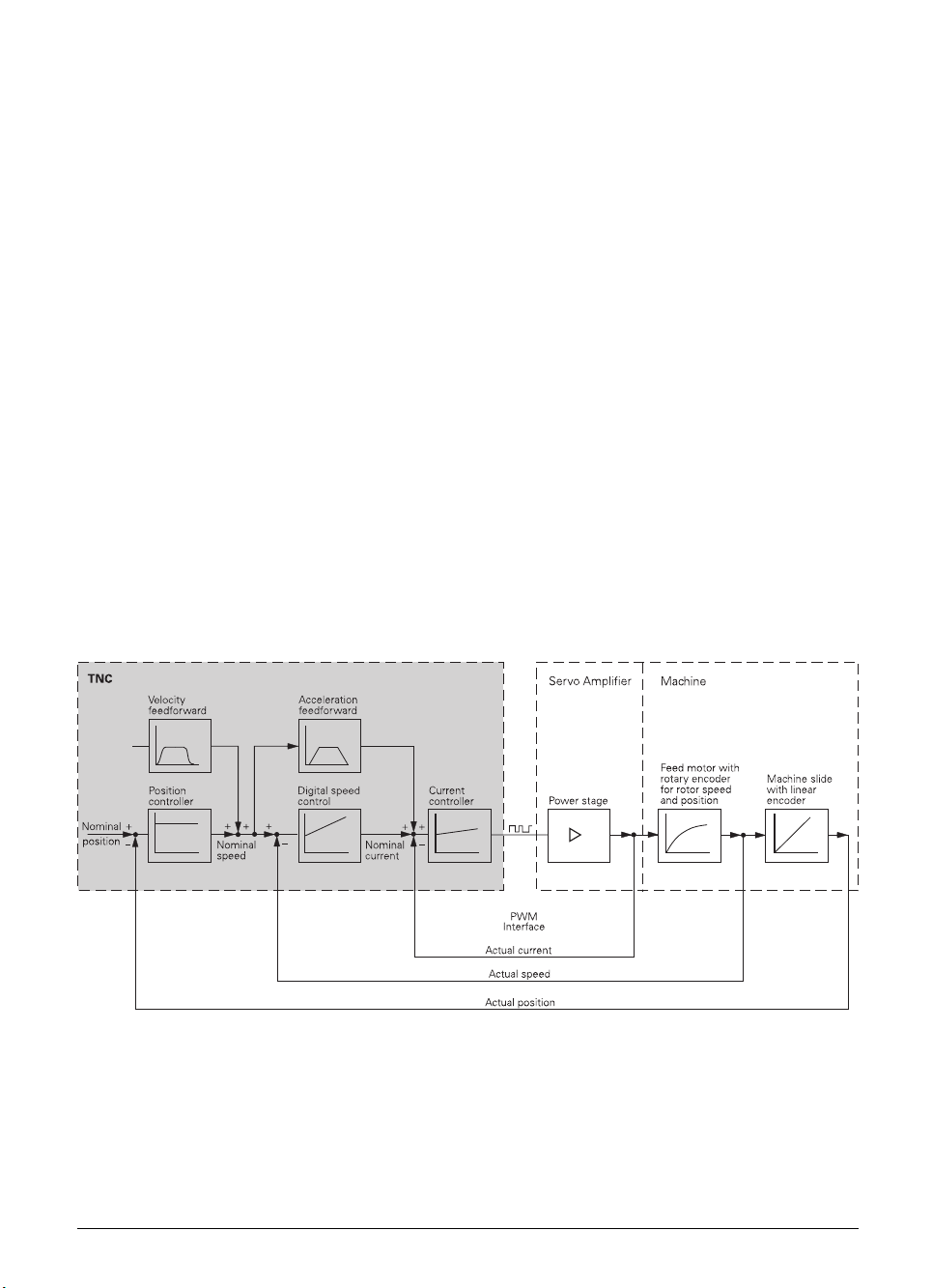
2.1 Integrated Current Control
HEIDENHAIN contouring controls are designed for integration in milling, drilling and boring machines
as well as machining centers.
The TNC 426 PB / TNC 430 PA has integral drive controllers; these control the drive amplifier by
means of Pulse Width Modulated (PWM) signals.
Integration of the drive controllers in the TNC 426 PB / 430 PA offers the following advantages:
• All the software is contained centrally in the NC; this means that the individual components of
the NC such as feed axes, spindle, NC or PLC are optimally matched.
• High control quality, because the position control, speed control and current control are
combined into one unit.
• For commissioning, optimization and diagnosis, the same functions are available both for the
feed drive and the main spindle.
The TNC 426 PB can control machines with up to five axes and spindle speeds up to 9000 rpm,
option: 15 000 rpm (spindle speeds are valid for motors with two pole pairs). Powerful
microprocessor hardware and an integrated hard disk with 900 MB guarantee almost unlimited NC
memory and a short processing time — even for long programs. These are ideal preconditions for
tool and mold construction.
The TNC 430 PA supports six digitally controlled NC axes and three analog controlled secondary
axes, as well as digitally controlled spindle speeds up to 15 000 rpm (for motors with two pole pairs).
Control concept of the TNC 4xx PA
The TNC 426 CB is the version of the TNC 426 that is equipped with analog speed command
interface and can control machines with up to five axes plus spindle.
The TNC 430 CA also has analog speed command interface for machines with up to eight axes plus
spindle. A ninth axis can be controlled with an additional PCB.
November 97 Integrated Current Control TNC 426 B, TNC 430 2–1
Page 27

2.2 Brief Description
Technical Data TNC 426 TNC 430
Basic model with integral drive
control
All position encoder and motor encoder inputs 1 V
TNC 426PB:
5 axes plus spindle
(max. 9000 rpm, option:
15 000 rpm) with position
encoder and motor encoder
inputs.
TNC 430PA:
• 5 axes plus spindle
(max. 15000 rpm) with
position encoder and motor
encoder inputs
th
axis with motor encoder
•6
input
PP
Basic model with analog speed
All position inputs 1 V
PP
command interface
TNC 426CB:
5 axes plus spindle
Options Position inputs for the axes:
11 µA
PP
–
• Digitizing with 3-D triggering touch probe
• Digitizing with 3-D measuring touch probe
• Ethernet interface
Display 15-inch CRT color monitor
Program memory Hard disk with 900 MB
Input precision and
display step
Interpolation
Straight lines 5 of 5 axes 5 of 9 axes
Circular arcs 2 of 5 axes;
Helices Combination of circular and linear motion
Spline
Block processing time From the hard disk: 4 ms
Up to 0.1 µm for linear axes
Up to 0.0001° for angular axes
3 of 5 axes with tilted
working plane
–
TNC 430CA:
8 axes plus spindle
–
TNC 430CA:
Position input for 9
th
axis
TNC 430PA:
• Position inputs for 3
additional axes with analog
speed command interface
• Position input for 6
th
axis
2 of 9 axes;
3 of 9 axes with tilted
working plane
Cubical splines can be input
2–2 TNC 426 B, TNC 430 Brief Description November 97
Page 28

Machine Integration TNC 426 TNC 430
Control
Integral drive control TNC 426 PB TNC 430PA
Analog speed command
interface
Position loop resolution
Cycle time: path
interpolation
Cycle time: speed TNC 426 PB, TNC 430PA: 0.6 ms
Feed rate
Speed
Error compensation Linear / non-linear axis error, backlash, reversal spikes during
Integrated PLC
PLC memory Hard disk
Main memory (RAM) 128 KB (approx. 16000 commands)
PLC cycle time 21 ms
PLC inputs 24 Vdc 56 (additional inputs as option: see PL 410B)
PLC outputs 24 Vdc 31 (additional outputs as option: see PL 410 B)
Analog inputs ±10 V 3 (additional analog inputs as option: see PL 410 B)
Analog outputs ±10 V TNC 426 PB: 13
Inputs for thermistors 3 (additional inputs as option: see PL 410B)
Commissioning aids • Oscilloscope
Data interfaces • One each RS-232-C/ V.24 and RS-422/ V.11 up to 115 kbaud
TNC 426CB TNC 430CA
Signal period
1024
3 ms
TNC 426PB, TNC 430 PA:
TNC 426 CB, TNC 430 CA: Up to 60
TNC 426PB (standard):
TNC 426PB (option), TNC 430 PA:
TNC 426 CB, TNC 430 CA: 100 000
circular movements, offset, thermal expansion, stiction,
sliding friction
TNC 430CB: 7 (with 5 NC
axes + spindle)
• Trace function
• Expanded data interface with LSV2 protocol for external
operation of the TNC
• Option: Ethernet interface, approx. 200 to 1000 kilobaud
18 000
No. pole pairs
20 µm grating period
Up to 300
100 µm grating period
TNC 430 PA: 13
TNC 430 CA: 3 (with 9 NC
axes + spindle)
• Screw pitch
m
for encoders with
min
m
for encoders with
min
18 000
No. pole pairs
30 000
No. pole pairs
1
min
min
min
1
1
1
min
November 97 Brief Description TNC 426 B, TNC 430 2–3
Page 29

User Functions TNC 426 TNC 430
Programming HEIDENHAIN plain language and ISO
Position data Nominal positions for straight lines and circular arcs in Cartesian
or polar coordinates, absolute or incremental dimensional data,
display and entry in mm and inches
Contour approach and departure • Via straight line: tangential or perpendicular (APPR/DEP),
• Via circular arc (APPR-/DEP)
• Via rounding radius (RND)
Tool compensation • Tool radius in the working plane and tool length
• Radius-compensated contour look ahead for up to 99 blocks
(M120)
Cutting data tables For the automatic calculation of speed and feed rate from
various definable cutting/workpiece material combinations
Constant contouring speed • Relative to the tool's center point path
• Relative to the tool's cutting edge (M109, M110, M111)
3-D machining • Insertion of rounding radius between two straight line
segments (M112, M113, M124)
• Feed rate reduction during plunging (M103)
• 3-D tool compensation through surface normal vectors
• Automatic compensation of machine geometry when
working with tilted axes (M114, M115, M128, M130)
• Changing the position of the swivel head with the electronic
handwheel during program run. The position of the tool tip
does not change.
• Jolt reduction
• Spline
Machining with rotary tables • Programming of cylindrical contours
• Feed rate in mm/min (M116)
FK free contour programming FK free contour programming in HEIDENHAIN plain language
with graphic support for workpiece drawings not dimensioned
for NC
Subprogramming Program section repeats, subprograms, program calls
Background
programming
Fixed cycles • Peck drilling, tapping with or without a floating tap holder,
Coordinate transformation • Datum shift, rotation, mirror image
Creating programs while another program is being run, also with
graphic support
reaming, boring, hole patterns, slot milling, rectangular and
circular pocket milling, multipass milling of plane surfaces
• OEM cycles (special cycles developed by the machine tool
builder) can also be integrated.
• Contour pockets – also contour-parallel
• Contour train
• Scaling factor (axis specific)
• Tilting the working plane
2–4 TNC 426 B, TNC 430 Brief Description November 97
Page 30

User Functions TNC 426 TNC 430
Q parameters; programming
with variables
Programming aids • Pocket calculator
Teach in Actual positions can be transferred directly into the NC program
Test graphics Graphic simulation before a program run:
Programming graphics In the Programming and Editing operating mode, the contours of
Program run graphics; display
modes
Machining time • Calculation of machining time in the Test Run operating
Returning to the contour • Mid-program startup in any block in the program, returning
Datum tables Several datum tables, each with 254 datums
Pallet tables Several pallet tables with various different entries for selection
• Mathematical functions =, +,–, *, ÷, sin α, cos α,
angle α from sin α and cos α, a, a² + b²
• Logical comparisons (=, ≠, <, >)
• Parentheses
• tan α, arc sin, arc cos, arc tan, an, en, ln, log, absolute value
of a number, constant π, negation
decimal point
• Structuring of part programs
• Graphic support for the programming of cycles
• Plan view
• Projection in three planes
• 3-D representation
• Magnification of details
the NC blocks are drawn while they are being entered
(2-D pencil-trace graphics)
Graphic simulation during real time machining:
• Plan view
• Projection in three planes
• 3-D representation
mode
• Display of the current machining time in the program run
modes
the tool to the calculated nominal position to continue
machining
• Program interruption, contour departure and reapproach
of pallets, NC programs and datums
truncation before or after
,
Export versions TNC 426 CF, TNC 426 PF TNC 430 CE, TNC 430 PE
Linear interpolation 4 of 5 axes 4 of 9 axes
November 97 Brief Description TNC 426 B, TNC 430 2–5
Page 31

Accessories TNC 426 TNC 430
Electronic handwheels One HR 410 portable handwheel, or
one HR 130 panel-mounted handwheel, or
up to 3 HR 150 panel-mounted handwheels via HRA 110
handwheel adapter
Superimpose handwheel positioning during program run (M118)
Touch probe systems TS 220 3-D triggering touch probe with cable
connection, or
TS 630 3-D triggering touch probe with infrared
transmission
TT 120 3-D triggering touch probe for tool
measurement and inspection
Digitizing of 3-D surfaces • Option: with the TS 220 3-D triggering touch probe and a
software module for the TNC
• Option: adapter kit for a 3-D measuring touch probe.
• PC evaluation software for digitized data: SUSA
PC evaluation software for
SUSA for PCs
digitized data
Interface card TNC 426 PB, TNC 430 PA: For connection of
power modules for the SIMODRIVE 611 inverter system
Protective PCB for dc-link
power supply
Protective PCB for integration in the SIEMENS input module to
secure the dc-link power supply of the logic unit.
PLC input/output unit Up to four PL 410 B
Version 1:
Additional 64 PLC inputs and 31 PLC outputs per input/output
unit
Version 2:
Additional 64 PLC inputs and 31 PLC outputs, plus four
± 10 V analog inputs and 4 inputs for thermistors per
input/output unit
2–6 TNC 426 B, TNC 430 Brief Description November 97
Page 32

2.3 Software
The logic unit contains separate software for the NC section and the PLC section. The software is
identified by an eight-figure number.
After switching on the control, the NC software, PLC software and software-options
numbers are displayed on the screen. The software number can also be directly requested with the aid
of the MOD function.
2.3.1 NC Software
NC software number
The first 6 figures of the NC software number identify the type of control, the last two identify the
version of the software.
Software type
Due to restrictions on the export of the TNC, HEIDENHAIN can also deliver a special export version.
This export version differs from the standard control through the installed software type.
HEIDENHAIN assigns a new software type whenever comprehensive new functions are introduced.
Software type Linear interpolation
TNC 426 PB, TNC 426 CB
TNC 430 PA, TNC 426 CA
TNC 426 PF, TNC 426 CF
TNC 430 PE, TNC 426 CE
280 470 280 472 Up to 5 axes
280 471 280 473 Up to 4 axes
2.3.2 Software Option
HEIDENHAIN offers “Digitizing with a Triggering Touch Probe” and “Digitizing with Triggering and
Measuring Touch Probes” as software options (see chapter “Machine Integration”). Whenever a
contouring control is ordered with one of these options, HEIDENHAIN installs an additional software
module or PCB in the logic unit and assigns another variant to the part identification number (Id. Nr.)
of the logic unit. The option number is displayed on the screen in addition to the NC and PLC
software numbers.
Logic units already in the field can be retrofitted by the end user with the digitizing software
module. Please contact HEIDENHAIN
Option Option No. Id. Nr. of the
Digitizing with triggering touch probe 1 286 405 01 246 051 01
Digitizing with measuring and triggering
touch probes
SP 2/1 11 311 647 51 –
November 97 Software TNC 426 B, TNC 430 2–7
for more information.
component set
Id. Nr. of the
software module
Page 33

2.3.3 PLC Software
The PLC software is stored on the hard disk of the TNC. HEIDENHAIN has developed a PLC
commissioning program for the TNC. The source code is available from HEIDENHAIN. This program
can be easily adapted to suit your machine with the PLC programming software PLCdesign.
2.3.4 Software Exchange
The NC software is located on EPROMs (the sockets are illustrated below). The dialog languages are
stored on the hard disk. If there are no up-to-date dialog languages on the hard disk, load the English
dialog language from the EPROMs (selectable with MP7230.x). If a software exchange becomes
necessary, HEIDENHAIN
dialog languages.
Procedure for software exchange:
The software must be exchanged only by trained personnel.
⇒ Enter the code number 95148
⇒ Press the MOD key
⇒ Press the UPDATE DATA and CONVERT BIN=>ASC soft key:
All files on the hard disk will be converted from binary to ASCII format. The free space on the
hard disk must be at least 50% larger than the largest file. If this is not the case you must save
this file through the data interface. The extensions of the binary files and of the corresponding
converted ASCII files are:
.H ⇔ .H% .I ⇔ .I% .T ⇔ .T%
.TCH ⇔ .TC% .D ⇔ .D% .P ⇔ .P%
.PNT ⇔ .PN% .COM ⇔ .CO% .CMA ⇔ .CM%
⇒ Exchange the EPROMs
will provide the EPROMs with the NC software and a floppy disk with all
Sockets on processor board
IC 3
NC 4 MB
IC S
SW module
Danger of electrical shock!
Switch off the main switch before opening the housing.
2–8 TNC 426 B, TNC 430 Software November 97
IC 1
NC 4 MB
IC 4
NC 4 MB
IC 2
NC 4 MB
Page 34

⇒ Edit or erase the machine parameters. You will find information on the machine parameters in
the MPDOC.A file on the supplied floppy disk.
⇒ Press the END key to exit the machine parameter editor. The error message LANGUAGE LOAD
ERROR appears.
⇒ On the PC, enter the SETUP command to load the NC dialogs, HEIDENHAIN cycles etc. from the
provided floppy disk. The floppy disk also contains a detailed description in the README.TXT file.
⇒ Press the UPDATE DATA and CONVERT ASC=>BIN soft key:
All files on the hard disk are converted from ASCII into binary format.
⇒ Reload the files that you have backed up through the data interface.
⇒ Switch the TNC off and on to activate the new NC dialogs.
2.3.5 Data Backup
HEIDENHAIN provides a free program, TNCBACK.EXE, for backing up files in the TNC 426. We
recommend to the manufacturer whenever he supplies a machine tool to also provide a floppy disk
containing a copy of all machine-specific data, backed up with TNCBACK.EXE. The floppy disk
must also contain a copy of TNCBACK.EXE.
Before exchanging his control unit, the customer can save the data from the TNC,
especially the TNC:\ partition with its directories containing the part programs (see the user's
instructions on the floppy disk).
2.4 Hardware
The eight-digit ID number of the logic unit consists of the 6-digit basic ID number followed by the 2digit version number. The basic ID number designates significant hardware differences (e.g. type of
logic unit encoder inputs). The version number identifies the following differences:
version xy:
x = Identifier for a hardware change
y = 3 = Export version with “Digitizing with Triggering Touch Probe” option
4 = Standard version with “Digitizing with Triggering Touch Probe” option
7 = Standard version with “Digitizing with Measuring and Triggering Touch Probes” option
8 = Export version without option
9 = Standard version without option
November 97 Hardware TNC 426 B, TNC 430 2–9
Page 35

2.4.1 ID Numbers
BC 120 BF 120
LE 426 CB
5 position inputs 1 V
1 spindle position 1 V
5 position inputs 1 V
1 spindle position 1 V
5 position inputs 11 µA
1 spindle position 1 V
(350 kHz)
PP
(350 kHz)
PP
(50 kHz)
PP
(350 kHz)
PP
(50 kHz)
PP
(350 kHz)
PP
LE 426 PB
5 position inputs 1 V
1 spindle position 1 V
6 motor encoder inputs 1 V
(350 kHz)
PP
(350 kHz)
PP
PP
Spindle with up to 9000 rpm Id. Nr. 312 000 .. Id. Nr. 313 527 ..
Spindle with up to 15 000 rpm Id. Nr. 315 475 .. Id. Nr. 318 178 ..
5 position inputs 1 V
1 spindle position 1 V
6 motor encoder inputs 1 V
(50 kHz)
PP
(350 kHz)
PP
PP
Spindle with up to 9000 rpm Id. Nr. 326 414 .. Id. Nr. 326 421 ..
Spindle with up to 15 000 rpm Id. Nr. 326 416 .. Id. Nr. 326 420 ..
5 position inputs 11 µA
1 spindle position 1 V
6 motor encoder inputs 1 V
PP
(350 kHz)
PP
PP
(50 kHz)
Spindle with up to 9000 rpm Id. Nr. 311 999 .. Id. Nr. 313 526 ..
Spindle with up to 15 000 rpm Id. Nr. 317 349 .. Id. Nr. 318 177 ..
LE 430 CA
8 position inputs 1 V
1 spindle position 1 V
5 position inputs 1 V
3 position inputs 1 V
1 spindle position 1 V
(350 kHz)
PP
(350 kHz)
PP
(50 kHz)
PP
(350 kHz)
PP
(350 kHz)
PP
LE 430 PA
5 position inputs 1 V
1 spindle position 1 V
7 motor encoder inputs 1 V
5 position inputs 1 V
1 spindle position 1 V
7 motor encoder inputs 1 V
(350 kHz)
PP
(350 kHz)
PP
PP
(50 kHz)
PP
(350 kHz)
PP
PP
Id. Nr. 312 001 .. Id. Nr. 313 524 ..
Id. Nr. 326 415 .. Id. Nr. 326 419 ..
Id. Nr. 312 002 .. Id. Nr. 313 525 ..
Id. Nr. 311 050 .. Id. Nr. 313 523 ..
Id. Nr. 326 418 .. Id. Nr. 326 424 ..
Id. Nr. 311 049 .. Id. Nr. 313 521 ..
Id. Nr. 326 417 .. Id. Nr. 325 716 ..
Version Change
xxx xxx 2x First issue
xxx xxx 3x More powerful inverter
xxx xxx 4x 4 MB RAM; 3-row VGA connection; 3-phase current controller
2–10 TNC 426 B, TNC 430 Hardware November 97
Page 36

TE 401 B
Suitable for BC 110 B (black) Id. Nr. 250 517 05
TE 420
Suitable for BC 120 / BF 120 (gray) Id. Nr. 313 038 10
MB 420
Suitable for BC 120 / BF 120 (gray) Id. Nr. 293 757 12
BC 110 B (black)
14-inch screen with color graphics
Id. Nr. 260 520 01
(640 x 490 pixels)
2-row/3-row adapter for connection to LE
Id. Nr. 313 434 01
with Id. Nr. xxx xxx 4x via connecting
cable Id. Nr. 312 878 ..
2-row/3-row adapter for connection to
Id. Nr. 324 862 01
LE with Id. Nr. xxx xxx 4x via connecting
cable Id. Nr. 250 477 ..
BC 120 (gray)
15-inch screen with color graphics
Id. Nr. 313 037 01
(640 x 490 pixels)
3-row/2-row adapter for connection to LE
Id. Nr. 313 434 02
with Id. Nr. xxx xxx 3x
BF 120
TFT color flat-panel display Id. Nr. 313 506 10
PL 410 B
64 switching inputs 24 Vdc
Id. Nr. 263 217 12
31 switching outputs 24 Vdc
64 switching inputs 24 Vdc
Id. Nr. 263 217 02
31 switching outputs 24 Vdc
4 analog inputs ±10 V
4 inputs for thermistors
November 97 Hardware TNC 426 B, TNC 430 2–11
Page 37

Options
Interface card for connection of
Id. Nr. 291 070 01
power modules for the SIMODRIVE 611
inverter system
Protective PCB for dc-link power supply Id. Nr. 296 965 01
Additional position input for a 6th/9
th
axis
Id. Nr. 311 537 51
(350 kHz)
Position inputs for 3 additional axes with
Id. Nr. 294 130 51
nominal speed command interface
(350 kHz)
Ethernet interface Id. Nr. 293 890 51
Digitizing with triggering 3-D touch probe Id. Nr. 286 405 01
Digitizing with measuring 3-D touch
Id. Nr. 311 647 51
probe (SP 2/1)
Adapter for encoder signals
TTL (HEIDENHAIN layout) / 1 V
TTL (SIEMENS layout) / 1 V
11 µAPP / 1 V
PP
PP
PP
Id. Nr. 317 505 01
Id. Nr. 317 505 02
Id. Nr. 313 119 01
2–12 TNC 426 B, TNC 430 Hardware November 97
Page 38

2.5 Release Dates
2.5.1 NC Software Versions 280 470 and 280 471
NC software Release date
280 470 01 05/96 Export version: 280 471 01
First release:
NC software Release date
280 470 02 06/96 Export version: 280 471 02
Improvements:
• M132 with TIME parameter
• Module 9035 Parameter 21: Control model
• M118, M120 also in ISO
• Cycle 27: Cylinder surface also in tilted working plane
• MP7680 Bit 9 was added
• MP2423, MP2425, MP2427, MP2433, MP2451, MP2451, MP7245, MP7250 were removed
• MP2402 was changed: Gain for axis current controller at maximum speed
NC software Release date
280 470 03 08/96 Export version: 280 471 03
Improvements:
• GROSS POSITIONING ERROR F is new
NC software Release date
280 470 04 09/96 Export version: 280 471 04
Improvements:
• MP6500 Bit 4 and Bit 5 were added
• FN18: Group numbers 350 and 500 are new
• FN17: Group number 500 is new
• A Q-parameter was added to the cycles for tool measurement (31 to 33), where the
measurement result will be stored
NC software Release date
280 470 05 12/96 Export version: 280 471 05
Improvements:
• Rotary axes can be synchronized axes
• MP7682 Bit 1 was added
• In the compensation value tables .CMA and .COM the numbers of the axes will be entered as
opposed to the names
• Threshold for PLC: Time Out was increased from 200% to 300%
• MP6500 Bit 5, Bit 6 and Bit 8 were added
• FN18: Group numbers 51 and 52 are new
• FN17: Group number 210 is new
• Input range for MP2500 and MP2501 increased to 1000
• The maximum number of points for all compensation value tables was increased to 1280
• Coded NC error messages are displayed in the conversational format
November 97 Release Dates TNC 426 B, TNC 430 2–13
Page 39

NC software Release date
280 470 06 2/97 Export version: 280 471 07
Improvements:
• Datums can be set using the keys A B, C, X, Y, Z, U, V, W, a, b, c, x, y, z, u, v, w
• The software also runs on the special hardware version of the LE 426 PB with spindle speeds up
to 15 000 rpm
• The NC software also runs on the new LE 426 B and LE 430 hardware with the
Id. Nr. xxx xxx 4x
NC software Release date
280 470 07 03/97 Export version: 280 471 07
Improvements:
• MP2541 and MP2551 (frequency filter for spindle) are new. Input as with MP2540 and MP2551
for the axes.
• The compensation of reversal peaks during circular traverse was improved (MP711.x to
MP716.x).
NC software Release date
280 470 08 5/97 Export version: 280 471 08
Improvements:
• Hungarian conversational language new
• D760 (offset for tilting axes, touch probe center offset) new
• MP750 and MP752 (compensation of reversal error) new
• MP3143 expanded:
3 = as for input value 1, however the second reference mark is evaluated first
NC software Release date
280 470 09 6/97 Export version: 280 471 09
Improvements:
• MP6500 expanded: bit 10 and bit 11
NC software Release date
280 470 10 7/97 Export version: 280 471 10
2–14 TNC 426 B, TNC 430 Release Dates November 97
Page 40

2.5.2 NC software versions 280 472 and 280 473
NC software Release date
280 472 01 4/97 Export version: 280 473 01
Improvements:
• New function "Fast contour milling": Cycle 32 or G62 and MP1091.x
• Automatic calculation of cutting data
• TCPM (Tool Center Point Management
during machine run. Any misalignments in tilted axes are then corrected automatically.
• Additional information with the HELP key
• Input menu for fixed input values can be selected with the GOTO key
(e.g. baud rate)
• New pallet management
• Freely-definable tables
• NC blocks can be transferred in spline format
• More hard-disk memory space (1.5 gigabytes)
• You can select between standard and enhanced file management with the MOD function PGM
MGT
• The positions of all nine axes are shown in the status display. The spindle position overwrites the
ninth axis
• Copying progress is shown in a superimposed window
• The number of Q parameters was increased from 299 to 399
• Q parameters also permissible in FK blocks
• M110 also effective in contour pocket cycle
• Cycle 204: Back boring
• With MP7682 Bit 2 you can set whether rotary axes should always be positioned by the shorter
path
• A chamfer feed rate can be entered in the NC block "Chamfer" (CHF)
• Cycle 19 "Machining plane" was expanded by the parameters feed rate and setup clearance
(only when the tilting axes are positioned with Cycle 19. This is set in MP7500)
• M114 can also be used with non-controlled or PLC axes
• Hungarian as additional conversational language
• All soft keys appear in the set conversational language
• Language-dependent soft keys for OEM cycles
• The soft keys for FK programming only appear once you press the FK key
• Soft key F for feed rate in the manual operating modes
• New soft key: INCREMENT OFF/ON
• New soft key: HIDE TOOLS OFF/ON: the only tools shown in the tool table are those in the tool
magazine
• New soft keys for copying fields in the tool table
• PLC soft keys can be added to NC soft-key rows
• Ethernet: the name of a network printer can be given
• The probe results of the manual probing function can be taken over immediately in the datum
tables
• MP6170, MP6171: Multiple measurement with measuring tolerance
• A separate block of calibration data for TS and TT for every traverse range
• With MP6500 Bit 4 you can set whether or not speed should be limited to 1000 rpm during tool
measurement with TT
• MP6500 Bit 9: Automatic determination of the basic rotation for the cubical probe contact
• W760: Angular misalignment of the tilting axes for automatic adjustment of the touch probe
center misalignment
• The TS calibration data can be stored in the tool table via soft key
November 97 Release Dates TNC 426 B, TNC 430 2–15
: With M128 you can superimpose manual axis traverse
)
Page 41

• Cycles 31 to 33 (Tool measurement) were expanded by the input field "Q parameters for result"
• With MP6500 Bit 5 and Bit 6 you can define how to proceed if tool breaks
• FN17, FN18 ID990 NR1 Programmed probing
• FN17: ID210 NR6 Tilting the working plane during program run active/inactive
• FN17: ID50 Overwrite tool table
• FN17: ID210 Overwrite basic rotation
• FN18 ID350 Enhanced touch probe data
• FN23: CDATA Calculating the circle center from 3 touch points
• FN24: CDATA Calculating the circle center from 4 touch points
• FN25: Setting the datum
• ISO: Cycles with a number ≥ 200 can be programmed with graphic support (also OEM cycles)
• ISO: Cycles G75 and G76 (Rectangular pocket) were expanded by the input field "corner radius"
• ISO: Parameter H (max. permissible angle) can be entered after M112
• ISO: G60 Running digitized data is new
• MP2000 was removed. Digital axes can be defined in MP120
• In the compensation value tables COM and CMA you can use soft keys to select the columns for
the desired axes
• Non-linear axis error compensation: Max. number of compensation points increased from 640 to
1280
• A formula can be input in MP2020 (Distance covered in one motor revolution)
• MP2541, MP2551: Frequency filter for spindle
• The number of tools in the tool table was increased from 254 to 37 767
• M4019: Reversing the count direction of the linear encoder on the spindle
• Cooperative multi-tasking in the PLC (SPAWN command)
• Automatic tool recognition (BIS)
• String operand S#Axx new
• Module 9019: Checking program storage
• Module 9035: Expansion of parameters 3, 1000, 1001
• Module 9038: Reading axis information
• Module 9096: Deleting a line in the tool table
• Module 9112: Sending ASCII characters via RS-232
• Module 9113: Receiving ASCII characters via RS-232
• Module 9151: Selecting traverse range and axis designation
• Module 9200/9201: Expanded (PLC soft keys can be added to NC soft-key rows)
• Module 9215: Superimposing PLC window
• Module 9270: Reading from OEM.SYS
• Module 9271: Writing to OEM.SYS
• Automatic offset compensation of the encoder signals
• The oscilloscope recordings can be stored in a file.
• MP7365.5: Selected oscilloscope channel (input $00000FF)
2–16 TNC 426 B, TNC 430 Release Dates November 97
Page 42

NC software Release date
280 472 02 7/97 Export version: 280 473 02
Improvements:
• Cycle 32 changed to "Tolerance"
• M134 new
• System file TNC.SYS new
• MP6500 expanded: Bit 10 Probing routine, Bit 11 Checking tool and changing the tool table
• MP7500 expanded: Bit 3 Setting the datum in a tilted coordinate system
• Editor for creating the format of freely-definable tables
• FN18: ID200 and ID270 new
• FN17: ID350 new
• M4161 new
• PLC commands BTX, BCX, and BSX new
NC software Release date
280 472 03 8/97 Export version: 280 473 03
Improvements:
• Spline blocks also in tilted working plane
• MP7680, bit 10 new (spline at compensated outside corners)
• This software also runs on the old LE 426 CB/PB and LE 430 CA/PA hardware, however with
reduced function range
• Cycle 19: Dialog box "Setup clearance" new
NC software Release date
280 472 04 10/97 Export version: 280 473 04
Improvements:
• Code words LSV2TIME0 to LSV2TIME2 new
• Module 9038 expanded by transfer parameter –1
• DR2 can now be defined in TOOL CALL block
• Spindle DSP limits maximum torque to 2.5 • rated torque
November 97 Release Dates TNC 426 B, TNC 430 2–17
Page 43

✎
2–18 TNC 426 B, TNC 430 Release Dates November 97
Page 44

3 Mounting and Electrical Installation
3.1 Electrical Noise Immunity
Location for use
This device corresponds to Class A according to EN 55022 and is intended primarily for operation in
industrially zoned areas.
Remember that the vulnerability of electronic equipment to noise increases with faster signal
processing and higher sensitivity. Protect your equipment by observing the following rules and
recommendations.
Noise voltages are mainly produced and transmitted by capacitive and inductive coupling. Electrical
noise can be picked up by the inputs and outputs to the equipment, and the cabling.
Likely sources of interference are:
• Strong magnetic fields from transformers and electric motors
• Relays, contactors and solenoid valves
• High-frequency equipment, pulse equipment and stray magnetic fields from switch-mode power
supplies
• Mains leads and leads to the above equipment
Electrical interference can be avoided by:
• A minimum distance between the logic unit (and its leads) and interfering equipment > 20 cm.
• A minimum distance between the logic unit (and its leads) and cables carrying interference
signals > 10 cm. (Where signal cables and cables that carry interference signals are laid together
in metallic ducting, adequate decoupling can be achieved by using a grounded separation shield.)
• Shielding according to IEC 742 EN 50 178.
• Potential compensating lines dia. ≥ 6 mm² (see Grounding Diagram).
• Use of original HEIDENHAIN cables, connectors and couplings.
November 97 Electrical Noise Immunity TNC 426 B, TNC 430 3–1
Page 45

3.2 Heat Generation and Cooling
Please note that the reliability of electronic equipment is greatly reduced by continuous operation at
high temperatures. Be sure to make the necessary arrangements to keep within the permissible
ambient temperature range.
Permissible ambient temperature in operation: 0° C to 45° C
The following means may be employed to ensure adequate heat removal:
• Provide sufficient space for air circulation.
• Build in a ventilator fan to circulate the air inside the control cabinet. The fan must reinforce the
natural convection. It must be mounted so that the warm air is extracted from the logic unit and
no pre-warmed air is blown into the unit. The warmed-up air should flow over surfaces that have
good thermal conductivity to the external surroundings (e.g. sheet metal).
• For a closed steel housing without assisted cooling, the figure for heat conduction is 3 watt/m² of
surface per °C air temperature difference between inside and outside.
• Use of a heat exchanger with separate internal and external circulation.
• Cooling by blowing external air through the control cabinet to replace the internal air. In this case
the ventilator fan must be mounted so that the warm air is extracted from the control cabinet
and only filtered air can be drawn in. HEIDENHAIN advises against this method of cooling, since
the function and reliability of electronic assemblies are adversely affected by contaminated air
(fine dust, vapors etc.). In addition to these disadvantages, a filter that is not adequately serviced
leads to a loss in cooling efficiency. Regular servicing is therefore absolutely vital.
LE
Incorrect
Obstructive
elements
Heat generating
elements
Correct
LE
3–2 TNC 426 B, TNC 430 Heat Generation and Cooling November 97
Page 46

3.3 Humidity
Permissible humidity: < 75% in continuous operation,
< 95% for not more than 30 days p.a. (randomly distributed).
In tropical areas it is recommended that the TNC not be switched off, so that condensation is
avoided on the circuit boards. The heat generation prevents condensation and has no further
disadvantages.
3.4 Mechanical Vibration
Permissible vibration: < 0.5 g
3.5 Mounting Position
Note the following fundamental points on mounting:
• mechanical accessibility,
• permissible environmental conditions,
• electrical noise immunity,
• the electrical regulations that are in force in your country.
November 97 Humidity TNC 426 B, TNC 430 3–3
Page 47

LE 426 CB Logic Unit, TNC 430 CA
>110
>4.33"
Minimum clearance
for servicing!
recommended: =
approx. 250 mm
40
1.57"
80
3.15"
°C
>577
>22.72"
80
3.15"
Air outlet
*
°C
**
40
1.57"
30
100
3.94"
1. 1 8 "
Maintain clearance
for screwdriver
Connecting cables
must not hinder
swivel movement
of the control
9.65"
30
1. 1 8 "
83
3.27"
40
1.57"1.57"
°C
*
40
B
246
°C
*
6.3"
160
30
1. 1 8 "
**
°C
°C
**
R 325
R 12.8"
Air inlet
°C
*
**
°C
Measuring point for
ambient temperature
Free space for air circulation
Free space for servicing
Illustration of
max. swivel range.
The minimum angle of
swivel for exchange
of subassemblies should
be at least 90°.
100
3.94"
145
5.71"
40
1.57"
3–4 TNC 426 B, TNC 430 Mounting Position November 97
40°
Page 48

LE 426 PB Logic Unit, TNC 430 PA
>110
>4.33"
Minimum clearance
for servicing!
recommended: =
approx. 250 mm
Maintain clearance
for screwdriver
Connecting cables
must not hinder
swivel movement
of the control
307
12.09"
40
1.57"
80
°C
°C
>577
>22.72"
80
3.15"3.15"
Air outlet
**
°C
*
40
1.57"
°C
30
100
3.94"
1. 1 8 "
*
6.3"
160
30
1. 1 8 "
*
Air inlet
*
°C
100
3.94"
40
40
40
1.57"
1.57"1.57"
83
3.27"
°C
B
*
40°
30
1. 1 8 "
*
°C
R 331
R 12.8"
Measuring point for
°C
*
ambient temperature
Free space for air circulation
Free space for servicing
Illustration of
max. swivel range.
The minimum angle of
swivel for exchange
of subassemblies should
be at least 90°.
215
8.46"
November 97 Mounting Position TNC 426 B, TNC 430 3–5
Page 49

Visual Display Unit
BC 120
When mounting the BC 120, remember that this unit is very sensitive to magnetic or electromagnetic pick-up. The picture can be disturbed by strong magnetic fields. For this reason, keep a
minimum distance of 0.5 m between the VDU housing and the source of any disturbance (e.g.
permanent magnets, motors, transformers etc.).
Free space for air circulation, see dimension drawing in Appendix
BF 120
The BF 120 flat-panel display must be viewed at the so-called "6 o'clock angle". Thus the display
must be mounted as shown below.
α
BF 120
TE
150° > α > 90°
PLC Input/Output Unit
Up to four PL 410 B input/output units can be connected to the TNC.
TNC 426 CB, TNC 430 CA: One PL can be mounted on the logic unit. the others must be
mounted in a separate switch cabinet.
TNC 426 PB, TNC 430 PA: No PL can be mounted on the logic unit.
3.6 Degree of Protection
When mounted, the visual display unit and the keyboard unit provide class IP54 protection against
dust and splashwater.
3–6 TNC 426 B, TNC 430 Degree of Protection November 97
Page 50

3.7 Connection Overview
3.7.1 LE 426 CB
X44
X2
X1
X13
X48
X1
to
X5 Position encoder
X31
X25
X26
X4
X6
X9
X14
X30
X12
X23
X21
X22
X8
X41
X45
X42
X43
X46
X47
X3
X5
B
X6 Encoder for spindle
X8 Analog output 1 to 6
X9 Analog output 7 to 13
X12 Triggering touch probe for workpiece measurement
X13 Triggering touch probe for tool measurement
X14 Measuring touch probe (option)
X21 RS-232-C/V24 data interface
X22 RS-422/V11 data interface
X23 Handwheel input
X25 Ethernet interface (option)
X26 Ethernet interface (option)
X30 Reference signal for spindle
X31 NC power supply
X41 PLC output
X42 PLC input
X43 CRT visual display unit or
X49 Color flat panel display
X44 PLC power supply
X45 TNC keyboard
X46 Machine operating panel
X47 PLC expansion
X48 PLC analog input
B Signal ground
Protective ground (YE/GN)
Danger to internal components!
Do not engage or disengage any connections while the unit is under power.
3–8 TNC 426 B, TNC 430 Connection Overview November 97
Page 51

3.7.2 LE 426 PB (Spindle with up to 9000 rpm)
X1
X2
X1
X13
X44
X48
X15
X51X16
to
X5 Position encoder
X31
X25
X26
X4
X6
X9
X14
X30
X6 Encoder for spindle
X8 Analog output 1 to 6
X9 Analog output 7 to 13
X12 Triggering touch probe for workpiece
measurement
X13 Triggering touch probe for tool
measurement
X14 Measuring touch probe (option)
X15
to
X20 Speed encoder
X21 RS-232-C/ V24 data interface
X22 RS-422/V11 data interface
X23 Handwheel input
X25 Ethernet interface (option)
X26 Ethernet interface (option)
X30 Reference signal for spindle
X3
X5
X12
X23
X21
X22
X8
X41
X42
X46
X45
X43
X47
X18
X20
X52
X17
X53
X19
X54
X55
X57
X56
X50
X31 NC power supply
B
X41 PLC output
X42 PLC input
X43 CRT visual display unit or
X49 Color flat panel display
X44 PLC power supply
X45 TNC keyboard
X46 Machine operating panel
X47 PLC expansion
X48 PLC analog input
X50 Input for drive motor enabling
X51
to
X56 Output to motor power stage
X57
Reserved
B Signal ground
Protective ground (YE/GN)
Danger to internal components!
Do not engage or disengage any connections while the unit is under power.
November 97 Connection Overview TNC 426 B, TNC 430 3–9
Page 52

3.7.3 LE 426 PB (Spindle with up to 15 000 rpm)
X1
X2
X1
X13
X44
X48
X15
X51X16
to
X5 Position encoder
X31
X25
X26
X4
X6
X9
X14
X30
X6 Encoder for spindle
X8 Analog output 1 to 6
X9 Analog output 7 to 13
X12 Triggering touch probe for workpiece
measurement
X13 Triggering touch probe for tool
measurement
X14 Measuring touch probe (option)
X15
to
X19 Speed encoder
X21 RS-232-C/ V24 data interface
X22 RS-422/V11 data interface
X23 Handwheel input
X25 Ethernet interface (option)
X26 Ethernet interface (option)
X30 Reference signal for spindle
X3
X5
X12
X23
X21
X22
X8
X41
X42
X46
X45
X43
X47
X18
X60
X61
X52
X17
X53
X19
X54
X55
X57
X50
X31 NC power supply
B
X41 PLC output
X42 PLC input
X43 CRT visual display unit or
X49 Color flat panel display
X44 PLC power supply
X45 TNC keyboard
X46 Machine operating panel
X47 PLC expansion
X48 PLC analog input
X50 Input for drive motor enabling
X51
to
X55 Output to motor power stage
X57
Reserved
X60 Encoder for spindle speed
X61 Output to motor power stage of the spindle
B Signal ground
Protective ground (YE/GN)
Danger to internal components!
Do not engage or disengage any connections while the unit is under power.
3–10 TNC 426 B, TNC 430 Connection Overview November 97
Page 53

3.7.4 LE 430 CA
X1
X2
X13
X44
X48
X1
to
X5 Position encoder
X31
X25
X26
X4
X6
X9
X14
X30
B
X3
X5
X35
X36
X37
X12
X23
X21
X22
X8
X41
X42
X46
X45
X43
X47
X6 Encoder for spindle
X8 Analog output 1 to 6
X9 Analog output 7 to 13
X12 Triggering touch probe for workpiece measurement
X13 Triggering touch probe for tool measurement
X14 Measuring touch probe (option), or
X38 Additional position encoder input (option)
X21 RS-232-C/V24 data interface
X22 RS-422/V11 data interface
X23 Handwheel input
X25 Ethernet interface (option)
X26 Ethernet interface (option)
X30 Reference signal for spindle
X31 NC power supply
X35
to
X37 Position encoder
X41 PLC output
X42 PLC input
X43 CRT visual display unit or
X49 Color flat panel display
X44 PLC power supply
X45 TNC keyboard
X46 Machine operating panel
X47 PLC expansion
X48 PLC analog input
B Signal ground
Protective ground (YE/GN)
Danger to internal components!
Do not engage or disengage any connections while the unit is under power.
November 97 Connection Overview TNC 426 B, TNC 430 3–11
Page 54

3.7.5 LE 430 PA
X1
X31
X25
X26
X2
X4
X6
X9
X14
X30
B
X3
X5
X35
X36
X37
X13
X12
X23
X21
X22
X8
X44
X41
X42
X46
X48
X45
X43
X47
X18
X20
X60
X61
X15
X17
X19
X57
X56
X51X16
X52
X53
X54
X55
X50
X1 to
X5 Position encoder
X6 Encoder for spindle
X8 Analog output 1 to 6
X9 Analog output 7 to 13
X12 Triggering touch probe for workpiece
measurement
X13 Triggering touch probe for tool
measurement
X14 Measuring touch probe (Option), or
X38 Additional position encoder input
(Option)
X15 to
X20 Speed encoder
X21 RS-232-C/ V24 data interface
X22 RS-422/V11 data interface
X23 Handwheel input
X25 Ethernet interface (Option)
X26 Ethernet interface (Option)
X30 Reference signal for spindle
X31 NC power supply
X35
to
X37 Position encoder for 3 axes with analog
speed command interface (Option)
X41 PLC output
X42 PLC input
X43 CRT visual display unit or
X49 Color flat panel display
X44 PLC power supply
X45 TNC keyboard
X46 Machine operating panel
X47 PLC expansion
X48 PLC analog input
X50 Input for drive motor enabling
X51 to
X56 Output to motor power stage
X57
Reserved
X60 Encoder for spindle speed
X61 Output to spindle drive power stage
B Signal ground
Protective ground (YE/GN)
Danger to internal components!
Do not engage or disengage any connections while the unit is under power.
3–12 TNC 426 B, TNC 430 Connection Overview November 97
Page 55

3.8 Power Supply
3.8.1 NC Power Supply
LE 426 CB, LE 430 CA:
An NC power supply of 140 Vac to 450 Vac at terminals U
and the LE 430 CA. Power supply monitoring is switched off with Module 9167. To ensure
compliance with the European standards for electromagnetic emission (EN 55022), the LE may be
connected to the public power lines only through an isolating transformer or in conjunction with line
filters. Compliance to these standards is one of the requirements for the use of the CE mark. If a line
filter is already provided for the power stage, this power supply may also be used for the LE.
LE 426 PB, LE 430 PA:
For the LE 426 PB and the LE 430 PA, an NC power supply of 330 Vac to 450 Vac must be
connected to U
and U2. Here however this must be supplied via an isolating transformer (100 VA)
1
with basic insulation according to IEC 742 EN 50 178.
To guarantee a secure power supply for the drive controllers in the event of a power failure,
the LE must be supplied with the DC link voltage of the power stage (385 Vdc to 660 Vdc) at the
terminals +U
and −U
Z
If the DC link voltage is guaranteed to be available after switching the main
.
Z
switch on, the power supply of 190 Vac to 440 Vac at terminals U1 and U2 can be omitted. In this
case, a jumper must be connected between +U
surge voltage (approx. 5 s) of up to 720 Vdc is permitted. If 720 Vdc is exceeded, the NC revokes
the pulse release (Reset
——————
) for the IGBT of the power stage. The motors run down out of loop and no
and U1. The rectified voltage is monitored. A brief
Z
feedback to the DC link is possible. If 385 Vdc is not reached (power fail), all drives are brought to a
stop under control. This power supply monitoring is enabled and disabled with Module 9167. If the
voltage falls below 155 Vdc, a control unit reset takes place; the dc link power supply disconnects at
135 Vdc.
and U2 is adequate for the LE 426 CB
1
X31 NC power supply
Terminals Assignment LE 426 PB, LE 430 PA LE 426 CB, LE 430
CA
Protective ground (YE/GN)
U
1
U
2
Phase 1 330 Vac to 450 Vac via 140 Vac to 450 Vac
Phase 2 isolating transformer 50 to
50 to 60 Hz
60 Hz
–U
Z
+U
Z
1) other voltage ranges available upon request
DC-link voltage – 385 Vdc to 660 Vdc
DC-link voltage
+
1)
–
Power consumption: approx. 55 W
Danger of electrical shock!
The dc-link power supply must be opened only by your HEIDENHAIN service agency.
November 97 Power Supply TNC 426 B, TNC 430 3–15
Page 56

The NC power supply is stored in the logic unit. You must provide fuse protection for the supply line.
To protect the circuitry of the dc-link voltage, HEIDENHAIN offers a protective PCB for installation in
SIEMENS power supply modules. This PCB is equipped with 4 A / 500 V fuses.
Id. Nr. 296 965 01
+
–
+
–
Siemens power supply module
X131
U1
V1
W1
3.8.2 Buffer Battery Backup
When the control is switched off, a buffer battery backup supplies the TNC with enough power to
prevent data being lost from the RAM memory. If the message EXCHANGE BUFFER BATTERY
appears on the TNC it is time for you to change the batteries. The batteries can be found in the logic
unit, beside the power supply (round, black housing). The TNC also has an energy storage
mechanism for supplying power to the TNC while the batteries are being changed (max. stored
energy time: 24 hours).
Danger of electrical shock!
The machine tool and the TNC should be switched off while the battery is being changed!
The buffer batteries may only be changed by trained personnel!
Battery type: 3 round cells, leak-proof, IEC designation "LR6"
3–16 TNC 426 B, TNC 430 Power Supply November 97
Page 57

3.8.3 PLC Power Supply
(whe
outputs
(whe
e
outputs are o
The PLC of the LE and PL is powered by the 24 Vdc control voltage of the machine, which is generated in
accordance with IEC 742 EN 50 178 (base insulation). Superimposed ac components, such as those
caused by a three-phase bridge rectifier without smoothing, are permissible up to a ripple factor of
5% (see DIN 40110/10.75, Section 1.2).
U
32.6 V
31 V
20.4 V
18.5 V
t
The 0 V-line of the PLC-power supply must be grounded with an earth lead (∅ ≥ 6 mm2) to the main
frame ground of the machine.
Supply
voltage
Voltage range,
mean dc voltage
Max. current
consumption
n half of the
are on simultaneously)
24 Vdc
IEC 742
EN 50 178,
base insulation
Lower limit
20.4 V
- - -
Upper limit
31 V
- - -
LE: 2 A
PL 410 B: 20 A
Voltage surges up to
36 V - - - for t < 100 ms are
permissible.
X44 PLC power supply for the LE
Terminal Assignment PLC outputs
1 + 24 Vdc cannot be
switched off via
O24 to O30
Control ready for operation
EMERGENCY STOP
2 +24 Vdc can be switched O16 to O23
3
off via EMERGENCY STOP
O0 to O15
40V
Danger to internal components!
Use only original replacement fuses.
Current consumption
n half of th
n
simultaneously)
LE: 48 W
PL 410 B: 480 W
If the TNC 426 is used as a programming station, the PLC power supply must also be connected
(connections no. 1 and 2).
November 97 Power Supply TNC 426 B, TNC 430 3–17
Page 58

Power supply for the PL 410 B
Terminal Assignment 1st PL 2nd PL 3rd PL 4th PL
X9 0 V
X10 +24 Vdc power for logic unit and for control-is-ready signal
X11 +24 Vdc power supply for
outputs
X12 +24 Vdc power supply for
outputs
X13 +24 Vdc power supply for
outputs
X14 +24 Vdc power supply for
outputs
O32 to O39 O64 to O71 O95 to O102 O127 to
O134
O40 to O47 O72 to O79 O130 to
O110
O48 to O55 O80 to O87 O111 to
O118
O56 to O62 O88 to O94 O114 to
O125
O135 to
O142
O143 to
O150
O151 to
O157
The PL 410 B input/output unit for the PLC is available as an option. It provides additional analog
inputs and inputs for Pt 100 thermistors. The power supply for these analog inputs and thermistors
must comply with IEC 742 EN 50 178, 5.88, “low-voltage electrical separation.”
X23 Power supply of analog inputs on the PL 410 B
Terminal Assignment
1 + 24 Vdc (IEC 742 EN 50 178, 5.88, low-voltage electrical separation)
20 V
3–18 TNC 426 B, TNC 430 Power Supply November 97
Page 59

3.8.4 Power Supply for the Visual Display Units
BC 120
Line voltage 100V to 240V
Frequency range 50 Hz to 60 Hz
Power consumption 80 W
Connection to line voltage via Euro connector
Terminal Assignment
L1 L1 (BK)
N MP (BL)
Protective ground (YL/GY)
BF 120
X1 Power supply
Terminal Assignment
1 +24Vdc operational voltage with basic insulation in accordance with
IEC 742, EN 50 178
20 V
Power consumption: 15 W
November 97 Power Supply TNC 426 B, TNC 430 3–19
Page 60

3.9 Measuring Systems
r
HEIDENHAIN TNC contouring controls are designed for use with incremental linear and angular
position feedback encoders as measuring systems.
It does not matter whether the encoders feature single or distance-coded reference marks,
the TNC supports both types. However, HEIDENHAIN recommends using encoders with distancecoded reference marks because they significantly reduce the traverse distance required to establish
the absolute position.
Maximum current consumption per encoder input: 200 mA
Maximum total current consumption for all encoder inputs:
TNC 426 CB, TNC 430 CA: 1.2 A
TNC 426 PB, TNC 430 PA 2.4 A
Use only original HEIDENHAIN encoder cables, connectors and couplings. For maximum cable
lengths see “Cable Overview.”
3.9.1 Encoders for Position
LE 426 PB Id. Nr. 311 999 .. 313 526 .. 317 349 .. 318 177 ..
LE 426 CB Id. Nr. 312 002 .. 313 525 ..
X1, X2, X3 X4, X5 Encoder 1, 2, 3, 4, 5 (11 µA
PP
)
Maximum input frequency: 50 kHz
Logic Unit Encoder cable
D-sub terminal
(male) 15-pin
Assignment D-sub connecto
(female) 15-pin
1 + 5 V 1 Brown
2 0 V 2 White
3I
4I
+ 3 Green
1
– 4 Yellow
1
5 0 V 5 White/Brown (internal shield)
6I
7I
+ 6 Blue
2
– 7 Red
2
80 V 8
9 + 5 V 9
10 I0+ 10 Gray
11 0 V 11
12 I0– 12 Pink
13 0 V 13
14
15
Do not assign
Do not assign
14
15
Housing External shield Housing External shield
The interface complies with the recommendations in IEC 742, EN 50 178 for separation
from line power.
3–20 TNC 426 B, TNC 430 Measuring Systems November 97
Page 61

Encoder (1 V
PP
)
Connection Id. Nr. Max. input
frequency
LE 426 PB
X6 311 999 .., 312 000 .., 313 526 .., 313 527 .., 315 475 ..,
350 kHz
317 349 .., 318 177 .., 318 178 .., 326 414 .., 326 416 ..,
326 420 .., 326 421 ..
X1 to X5 312 000 .., 313 527 .., 315 475 .., 318 178 .. 350 kHz
326 414 .., 326 416 .., 326 420 .., 326 421 .. 50 kHz
LE 426 CB
X6 312 001 .., 312 002 .., 313 524 .., 313 525 .., 326 415 ..,
350 kHz
326 419 ..
X1 to X5 312 001 .., 313 524 .. 350 kHz
326 415 .., 326 419 .. 50 kHz
LE 430 PA
X6 311 049 .., 313 521 .., 326 417 .., 325 716 .. 350 kHz
X1 to X5 311 049 .., 313 521 .. 350 kHz
325 716 .., 326 417 .. 50 kHz
X35 to X38 311 049 .., 313 521 .., 326 417 .., 325 716 .. 350 kHz
LE 430 CA
X6 311 050 .., 313 523 .., 326 418 .., 326 424 .. 350 kHz
X1 to X5 311 050 .., 313 523 .. 350 kHz
326 418 .., 326 424 .. 50 kHz
X35 to X38 311 050 .., 313 523 .., 326 418 .., 326 424 .. 350 kHz
November 97 Measuring Systems TNC 426 B, TNC 430 3–21
Page 62

Logic Unit Encoder cable
D-sub terminal
(male) 15-pin
1 + 5 V (UP) 1 Brown/Green
2 0 V (UN) 2 White/Green
3 A+ 3 Brown
4 A– 4 Green
50 V 5
6 B+ 6 Gray
7 B– 7 Pink
80 V 8
9 + 5 V 9 Blue
10 R+ 10 Red
11 0 V 11 White
12 R– 12 Black
13 0 V 13
14
15
Housing External shield Housing External shield
Assignment D-sub
connector
(female) 15-pin
Do not assign
Do not assign
14 Violet
15
The interface complies with the recommendations in IEC 742, EN 50 178 for separation
from line power.
3–22 TNC 426 B, TNC 430 Measuring Systems November 97
Page 63

3.9.2 Encoders for Speed (TNC 426 PB and TNC 430 PA Only)
X15 to X20, X60 Encoder for speed (1 VPP)
Maximum input frequency: X15 to X20, X60 350 kHz
X60 as of NC software 280 472 01 410 kHz
Logic unit Adapter Cable Id. Nr. 289 440 ..
D-sub terminal
(male) 25-pin
1(U
2 0 V (UN) 2 White/Green 7
3 A+ 3 Green/Black 1
4 A– 4 Yellow/Black 2
50 V 5
6 B+ 6 Blue/Black 11
7 B– 7 Red/Black 12
8 0 V 8 Internal shield 17
9
10 0 V 10
11
12
13 Temperature + 13 Yellow 8
14 + 5 V or not used
15 Analog output (test) 15
16 0 V 16 White 15
17 R+ 17 Red 3
18 R– 18 Black 13
19 C+ 19 Green 5
20 C– 20 Brown 6
21 D+ 21 Gray 14
22 D– 22 Pink 4
23 + 5 V (Test) 23
24 0 V 24
25 Temperature – 25 Violet 9
Housing External shield Housing External shield Housing
)
1
The operating voltage is set by jumper on the PCB to match the voltage of the connected encoders.
Assignment D-sub
connector
(female)
25-pin
) + 5 V or + 6.4V
P
Do not assign
Do not assign
Do not assign
1)
1 Brown/Green 10
9
11
12
1)
14 Blue 16
Connector
(female)
17-pin
The interface complies with the recommendations in IEC 742, EN 50 178 for separation
from line power.
X15 Axis 1 X18 Axis 4 X60 TNC 430 PA only: Spindle
X16 Axis 2 X19 Axis 5 TNC 426 PB (15 000):
X17 Axis 3 X20 TNC 430 PA: Axis 6
TNC 426 PB (9000): Spindle
November 97 Measuring Systems TNC 426 B, TNC 430 3–23
Page 64

3.9.3 Adapter for Encoder Signals
HEIDENHAIN offers a range of adapter connectors for adapting 11µAPP or TTL encoder signals to
the 1V
remains the same.
Remember also that a square-wave signal has only 4-fold evaluation (cannot be interpolated).
Neither can the TNC evaluate the fault detection signal of a square-wave encoder.
interface of the logic unit.
PP
Please note that these adapters change the signal levels only, while the form of the signal
>2 V
>2 V
SIEMENS
0
11µA
Id.-Nr. 317 505 01
Id.-Nr. 317 505 02
Id.-Nr. 313 119 01
1 V
LE
1 V
LE
U
0
1 V
LE
3–24 TNC 426 B, TNC 430 Measuring Systems November 97
Page 65

3.10 Motor Power Stage Connection
The SIMODRIVE 611 D is fitted with an expansion board ordered separately from HEIDENHAIN.
These expansion boards are designed for two axes (inputs X1 and X2) and are connected to the
logic unit via a connecting cable (see “Cable Overview”).
The expansion board must be connected according to the Basic Circuit Plan.
X51 to X56, X61 Output to motor power stage (only TNC 426 PB, TNC 430 PA)
Logic unit Connecting Cable
Id. Nr. 289 208 ..
D-sub terminal
(female) 15-pin
1
2 PWM U
3 PWM U
4 PWM U
5
6 Ready 6
7I
8I
9 0V U
10 0V U
11 0V U
12 0V (analog) 12 Yellow 12 12
13
14 I
15 I
Housing External shield Housing External
Assignment D-sub
connector
(male)
15-pin
Do not assign
1
2
3
Reset
– 7 Gray/Pink 7 7
actual. 2
– 8 Black 8 8
actual. 1
1
2
3
Tempertr. warning
+ 14 Red/Blue 14 14
actual. 2
+ 15 Violet 15 15
actual. 1
1 Black 1 1
2 Blue 2 2
3 Gray 3 3
4 White 4 4
5
9 Red 9 9
10 Pink 10 10
11 Brown 11 11
13
Green
White/Green
Brown/Green
shield
D-sub
connector
(female) 15-pin
55
66
13 13
Housing Housing
Expansion board
Id. Nr. 324 952 ..
X1, X2
D-sub terminal
(female) 15-pin
The interface complies with the recommendations in IEC 742, EN 50 178 for separation
from line power.
Logic level: 5 V
Analog signals I
: ± 7.5 V
actual
Maximum PWM frequency: 5 kHz
X51 Axis 1 X54 Axis 4 X61 Only TNC 430 PA: Spindle
X52 Axis 2 X55 Axis 5 TNC 426 PB (15 000):
X53 Axis 3 X56 TNC 430 PA: Axis 6
TNC 426 PB (9000): Spindle
November 97 Motor Power Stage Connection TNC 426 B, TNC 430 3–25
Page 66

Connection overview of the HEIDENHAIN expansion board
X1
NB
IF
K 663
K 9
X2
X351
AS 1
AS 2
X1 and X2 Connection to LE 426 PA / LE 430 PA
X351 SIMODRIVE hardware bus
NB (Red) Not ready
Monitoring of U
, temperature, power supply and pulse release
z
IF (Green) Pulse release
AS1 Forced break contact 1
AS2 Forced break contact 2
K663 Safety relay for pulse release
K9 Power supply from SIMODRIVE hardware bus
3–26 TNC 426 B, TNC 430 Motor Power Stage Connection November 97
Page 67

✎
November 97 Motor Power Stage Connection TNC 426 B, TNC 430 3–27
Page 68

✎
3–28 TNC 426 B, TNC 430 Motor Power Stage Connection November 97
Page 69

3.11 Analog Inputs
The logic unit and the PLC input/output board have analog inputs (± 10 V) and inputs for Pt 100
thermistors. The PL 410 B is available with or without analog inputs. The analog inputs must be
activated on the PL 410 B by a DIL switch.
Analog inputs (±10 V) Inputs for Pt 100 thermistors
Logic unit 3 3
PL 410 B 4 4
The current values of these inputs are interrogated with Module 9003.
Analog inputs:
Voltage range − 10 V to + 10 V
Input resistance > 250 kΩ
Resolution 100 mV
Internal value range – 100 to + 100
Inputs for Pt 100 thermistors:
Constant current 5 mA
Temperature range 0° C to 100° C
Resolution 0.5° C
Internal value range 0 to 200
November 97 Analog Inputs TNC 426 B, TNC 430 3–29
Page 70

X48 Analog input (PLC) on the LE
D-sub terminal
Assignment
(female) 25-pin
1I
2I
3U
4U
5I
6I
7U
8U
9I
+ Constant current for Pt 100
1
– Constant current for Pt 100
1
+ Measuring input for Pt 100
1
– Measuring input for Pt 100
1
+ Constant current for Pt 100
2
– Constant current for Pt 100
2
+ Measuring input for Pt 100
2
– Measuring input for Pt 100
2
+ Constant current for Pt 100
3
10 I3– Constant current for Pt 100
11 U3+ Measuring input for Pt 100
12 U3– Measuring input for Pt 100
14 Analog input 1 –10 V to +10 V
15 Analog input 1 0 V (reference potential)
16 Analog input 2 –10 V to +10 V
17 Analog input 2 0 V (reference potential)
18 Analog input 3 –10 V to +10 V
19 Analog input 3 0 V (reference potential)
13, 20 to 25
Do not assign
Housing External shield
The correct polarity of analog inputs is essential.
X15 to X18 Analog input on the PL 410 B
Terminal Assignment
1 –10 V to +10 V
2 0 V (reference potential)
3 Shield
3–30 TNC 426 B, TNC 430 Analog Inputs November 97
Page 71

X19 to X22 Connection for Pt 100 on the PL 410 B
1
2
4
5
Measuring input U+
Measuring input U–
→
I+
→
I–
3
Terminal Assignment
1 I + Constant current for Pt 100
2 U + Measuring input for Pt 100
3 U – Measuring input for Pt 100
4 I – Constant current for Pt 100
5 Shield
Connection to the analog inputs
Connecting cable, 2 x 0.14 mm
Connection to the inputs for Pt 100 thermistors
The connection to the Pt 100 thermistors must be arranged as a four-wire circuit.
e.g. PL 410 B X19:
Pt100 Customer's cable
2
shielded, max. 50 m.
4 x 0.14 mm² shielded, max. 50 m (164 ft)
November 97 Analog Inputs TNC 426 B, TNC 430 3–31
Page 72

3.12 Analog Outputs
Maximum loading of the analog outputs: 2 mA
Maximum capacitance: 2 nF
There are 13 analog outputs available:
• Connection X8: analog output 1 to 6
• Connection X9: analog output 7 to 13
PLC analog outputs
The PLC analog outputs can be switched via Module 9130.
Nominal value output:
• For analog axes and analog spindle, use MP120.x and MP121 to assign the corresponding analog
outputs on connection X8 or X9 to the nominal speed outputs.
• The connecting cables to the nominal value outputs must not have more than one intermediate
terminal.
• If it is necessary to branch to physically separate servo inputs, the connection must be made in a
grounded terminal box. Suitable terminal boxes is available from HEIDENHAIN (Id. Nr. 251 249
01).
• The chassis of the terminal box must be electrically connected with the frame of the machine.
• The 0 V connection of the nominal-value-difference inputs must be connected with signal
ground. Required cross section ≥ Ø 6 mm².
• Use only original HEIDENHAIN cables and connecting elements.
The following wiring plan is suggested for shielding the terminal box:
LE
•
1 2 3 4 5 6 7 8 9 1 0 11 12 13 14 15 16
Insulated against housing.
Leads are provided with end sleeves.
Cable shielding is led onto 14 mm²
insulated strands via crimp eyelets.
•
Z
IV V
S
Y
X
SERVO
3–32 TNC 426 B, TNC 430 Analog Outputs November 97
Page 73

Connection terminal Assignment
1 Nominal value output: ±10 V X axis
2 Nominal value output: 0 V X axis
3 Nominal value output: ±10 V Y axis
4 Nominal value output: 0 V Y axis
5 Nominal value output: ±10 V Z axis
6 Nominal value output: 0 V Z axis
7 Nominal value output: ±10 V Axis 4
8 Nominal value output: 0 V Axis 4
9 Nominal value output: ±10 V Axis 5
10 Nominal value output: 0 V Axis 5
11 Nominal value output: ±10 V Spindle
12 Nominal value output: 0 V Spindle
13 Shield connection
14 Shield connection
15 Shield connection
16 Shield connection
X8 Analog output 1 to 6
Logic unit Connecting Cable
D-sub terminal
(female) 15-pin
1 Analog output 1: ±10 V 1 BN
2
3 Analog output 2: ±10 V 3 YL
4 Analog output 5: ±10 V 4 RD/BL
5 Analog output 3: ±10 V 5 PK
6 Analog output 5: 0 V 6 GY/PK
7 Analog output 4: ±10 V 7 RD
8 Analog output 6: ±10 V 8 VI
9 Analog output 1: 0 V 9 WH
10
11 Analog output 2: 0 V 11 GN
12
13 Analog output 3: 0 V 13 GY
14 Analog output 4: 0 V 14 BL
15 Analog output 6: 0 V 15 BK
Housing External shield Housing External shield
Assignment D-sub
connector
(male) 15-pin
Do not assign
Do not assign
Do not assign
2 BN/GN
10 WH/GY
12
Color
November 97 Analog Outputs TNC 426 B, TNC 430 3–33
Page 74

X9 Analog output 7 to 13
Logic unit Connecting cable
D-sub terminal
(female) 15-pin
1 Analog output 7: ±10 V 1 BN
2 Analog output 13: ±10 V 2 BN/GN
3 Analog output 8: ±10 V 3 YL
4 Analog output 12: ±10 V 4 RD/BL
5 Analog output 9: ±10 V 5 PK
6 Analog output 12: 0 V 6 GY/PK
7 Analog output 10: ±10 V 7 RD
8 Analog output 11; ±10 V 8 VI
9 Analog output 7: 0 V 9 WH
10 Analog output 13: 0 V 10 WH/GY
11 Analog output 8: 0 V 11 GN
12
13 Analog output 9: 0 V 13 GY
14 Analog output 10: 0 V 14 BL
15 Analog output 11: 0 V 15 BK
Housing External shield Housing External shield
Assignment D-sub
connector
(male) 15-pin
Do not assign
12
Color
For connecting cable see “Cable Overview.”
3–34 TNC 426 B, TNC 430 Analog Outputs November 97
Page 75

3.13 Touch Probes
The following touch probes can be connected:
The triggering touch probes
TS 220 With cable connection; for digitizing, workpiece setup and measurement during
machining
or
TS 630 With infrared transmission; for workpiece setup and measurement during machining
and
TT 120 For tool measurement
and
One measuring touch probe
For information on touch probe connecting cables see “Cable overview.”
3.13.1 Triggering Touch Probe for Workpiece Measurement
X12 Triggering Touch Probe for workpiece measurement
Logic unit
D-sub terminal
(female) 15-pin
1 0 V (internal shield)
3 Ready
4 Start
5 +15 V ± 10% (UP)
6 + 5 V ± 5% (UP)
7
8 0 V (UN)
9 Trigger signal
10
2, 11 to 15
Housing External shield
Assignment
Battery warning
Trigger signal
1)
Do not assign
1) Stylus at rest means logic level High.
The interface complies with the recommendations in IEC 742, EN 50 178 for separation
from line power.
November 97 Touch Probes TNC 426 B, TNC 430 3–35
Page 76

Adapter Cable
Id. Nr. 274 543
D-sub
connector
(male) 15-pin
3 Pink 4 4 Gray
5 Gray
6 Brown/Green 2 2 Brown
7 Gray 3 3 Gray
8 White/Green 1 1 White
9 Green 5 5 Green
10 Yellow 6 6 Yellow
Housing External shield Housing Housing External shield
Connecting Cable Id. Nr. 310 197 .. EA Id. Nr. 262 904 01 TS 630
D-sub
connector
(male) 15-pin
1 White/Brown
Internal shield
3 Gray 5 5 Gray
4 Yellow 3 3
5 Brown 2 2 Brown
7 Blue 6 6 Blue
8 White 1 1 White
10 Green 4 4 Green
Housing External shield Housing Housing External shield
Coupling on
mounting base
6-pin
Connector
(female)
7-pin
7 7 Internal shield
TS120 Id. Nr. 265 348 ..
TS220 Id. Nr. 293 488 ..
Quick disconnect
6-pin
Coupling on
mounting
base 7-pin
Id. Nr.
293 714 ..
3–36 TNC 426 B, TNC 430 Touch Probes November 97
Page 77

3.13.2 Touch Trigger Probe for Tool Measurement
X13 Touch Trigger Probe for tool measurement
Logic unit
D-sub terminal
(female) 9-pin
1 Ready
2 0 V (UN)
4 +15 V ± 5% (UP)
7 +5 V ± 5% (UP)
8 Trigger signal
9
3, 5, 6
Housing External shield
1)
Stylus at rest means logic level High.
The interface complies with the recommendations in IEC 742, EN 50 178 for separation
from line power.
Adapter Cable Id. Nr. 310 200 .. TT 120 Id. Nr. 295 743 03
D-sub
connector
(male) 9-pin
1 Pink 6 6
2 White/Green 1 1 White
4 Gray 5 5
7 Brown/Green 2 2 Brown
8 Green 3 3 Green
9 Yellow 4 4 Yellow
Housing External shield Housing Housing External shield
Assignment
Trigger signal
Do not assign
1)
Coupling on
mounting base
(female) 6-pin
Connector
(male) 6-pin
November 97 Touch Probes TNC 426 B, TNC 430 3–37
Page 78

3.13.3 Measuring Touch Probe (Option)
In the standard version, the X14 socket is not present on the logic unit. With the "Digitizing with
measuring touch probe" option you receive an adapter kit with the X14 socket. In the TNC 430 you
can install either the adapter kit for the measuring touch probe at X14 or the adapter kit for an
additional linear encoder input X38.
• Adapter kit for SP 2/1 Id. Nr. 311 647 51
X14 Measuring Touch Probe SP 2/1
Logic unit (adapter kit
Id. Nr. 311 647 51)
D-sub
terminal
(female)
25-pin
3
4
16 Ua2 16 Gray 6
17 Ua1 17 Green 4
7
8
20 Ua2 20 White/Blue 10
21 Ua1 21 Blue 8
11
12
24 Ua2 24 Black 18
25 Ua1 25 Gray/Pink 12
1 0 V 1 White 1
5 + 12 V 5 Brown 3
9 Overtravel 1 9 White/Green 15
13 0 V 13
14 Overtravel 2 14 Brown/Green 21
18 ERROR 18 White/Gray 14
22
2, 6, 10,
15, 19, 23
Housing External shield Housing External shield Housing Housing
Assignment D-sub
connector
(male) 25pin
Ua2
Axis X 4 Yellow 5
Ua1
Ua2
Axis Y 8
Ua1
Ua2
Axis Z 12 Red/Blue 13
Ua1
SWITCH
Do not assign
3 Pink 7
7 Brown/Blue 11
11 Violet 19
22 Gray/Brown 20
Adapter Cable
Id. Nr. 296 839
Red 9
Coupling
on mounting base
(female)
21-pin
Connecting Cable A-1016-6640
Connector
(male)
21-pin
Renishaw
External
shield
Renishaw SP
2/1
Housing Housing
The interface complies with the recommendations in IEC 742, EN 50 178 for separation
from line power.
3–38 TNC 426 B, TNC 430 Touch Probes November 97
Page 79

✎
November 97 Touch Probes TNC 426 B, TNC 430 3–39
Page 80

✎
3–40 TNC 426 B, TNC 430 Touch Probes November 97
Page 81

3.14 Data Interface
-
The TNC features three data interfaces:
• one RS-232-C/V.24 data interface and
• one V.11/RS-422 data interface
• one Ethernet interface
Devices can be connected to all three interfaces, and the user can select which one he wishes to
use, see "Data Interface."
3.14.1 RS-232-C/V.24 Data Interface
• Maximum cable length is 20 meters (66 ft).
• To connect a peripheral device you must install an adapter cable either in the switching cabinet
or on the operating panel. See also the “Dimensions” section in the Appendix.
• For information on interface cables, see “Cable Overview.”
X21 RS-232-C/V.24 Data interface
Logic unit Connecting Cable
Id. Nr. 239 760 ..
D-sub
terminal
(female)
25-pin
1 GND 1 WH/BN
2 RXD 2 Green 3 3 3 3 Yellow 2
3 TXD 3 Yellow 2 2 2 2 Green 3
4 CTS 4 Gray 5 5 5 5 Pink 4
5 RTS 5 Pink 4 4 4 4 Gray 5
6 DTR 6 Blue 20 20 20 20 Brown 6
7 Signal GND 7 Red 7 7 7 7 Red 7
20 DSR 20 Brown 6 6 6 6 Blue 20
8 to 19,
21 to 25
Housing External
Assignment D-sub con
nector
(male) 25pin
Do not assign
Housing External
shield
External
shield
shield
D-sub
connector
(female)
25-pin
1 1 1 1 WH/BN
8888 8
Housing Housing Housing Housing External
Adapter Block
Id. Nr. 310 085 01
D-sub
terminal
(male)
25-pin
D-sub
terminal
(female)
25-pin
Connecting Cable
Id. Nr. 274 545 01
D-sub
connector
(male)
25-pin
External
shield
shield
The interfaces complies with the recommendations in IEC 742 EN 50 178 for separation
from line power.
D-sub
connector
(female)
25-pin
1
Housing
November 97 Data Interface TNC 426 B, TNC 430 3–41
Page 82

3.14.2 RS-422/V.11 Data Interface
• Maximum cable length is 1000 meters (3280 ft).
• To connect a peripheral device you must install an adapter cable either in the switching cabinet
or on the operating panel. See also the "Dimensions" section in the Appendix.
• For information on interface cables see “Cable Overview.”
Cable type LIYCY [7 (2 x 0.14 mm
2
)] Cu must be used for connection to the peripheral device.
HEIDENHAIN offers a 15-pin D-subminiature connector (Id. Nr. 315 650 03) for this cable.
X22 RS-422/V.11 Data interface
Logic unit Connecting Cable
Id. Nr. 289 208 ..
D-sub
terminal
(female)
15-pin
1 Chassis GND 1 Black
2 RXD 2 Blue 2 2 2
3 CTS 3 Gray 3 3 3
4 TXD 4 White 4 4 4
5 RTS 5 Green 5 5 5
6 DSR 6 White/Green 6 6 6
7 DTR 7 Green/Pink 7 7 7
8 Signal GND 8 Black 8 8 8
9
10
11
12
13
14
15
Housing External
Assignment D-sub
connector
(male)
15-pin
RXD
CTS
TXD
RTS
DSR
DTR
Do not assign
shield
9 Red 9 9 9
10 Pink 10 10 10
11 Brown 11 11 11
12 Yellow 12 12 12
13 Brown/Green 13 13 13
14 Red/Blue 14 14 14
15 Violet 15 15 15
Housing Housing Housing Housing
D-sub
connector
(female)
15-pin
111
External
shield
Adapter Block
Id. Nr. 311 086 01
D-sub
terminal
(male)
15-pin
D-sub
terminal
(female)
15-pin
The interfaces complies with the recommendations in IEC 742 EN 50 178 for separation
from line power.
3–42 TNC 426 B, TNC 430 Data Interface November 97
Page 83

3.14.3 Ethernet Interface (Option)
Maximum transfer speed: 200 to 1000 kilobaud
X25 Ethernet Interface RJ45 connection
Maximum cable length: unshielded: 100 m (329 ft)
shielded: 400 m (1312 ft)
RJ45 connection
(female) 8-pin
1 TX+
2 TX–
3 REC+
4
5
6 REC–
7
8
The interfaces complies with the recommendations in IEC 742 EN 50 178 for separation
from line power.
X26 Ethernet Interface BNC connection (coax cable)
Maximum cable length: 180 m
BNC connection (female) Assignment
Inner conductor (core) Data (RXI, TXO)
Shielding GND
Assignment
Do not assign
Do not assign
Do not assign
Do not assign
November 97 Data Interface TNC 426 B, TNC 430 3–43
Page 84

✎
3–44 TNC 426 B, TNC 430 Data Interface November 97
Page 85

3.15 Handwheel Input
The following handwheels are compatible with HEIDENHAIN contouring controls:
• One HR 130 panel-mounted handwheel, or
• HR 150 panel-mounted handwheels via HRA 110 handwheel adapter, or
• One HR 410 portable handwheel
3.15.1 Connector Assignment on the LE
X23 Handwheel Input
D-sub terminal
(female) 9-pin
20 V
4 +12 V ± 0.6 V (Uv)
6 DTR
7 TxD
8 RxD
9 DSR
1, 3, 5
Housing External shield
The interfaces complies with the recommendations in IEC 742 EN 50 178 for separation
from line power.
Assignment
Do not assign
November 97 Handwheel Input TNC 426 B, TNC 430 3–45
Page 86

3.15.2 HR 410 Portable Handwheel
)
The HR 410 is a portable electronic handwheel with:
• Five axis-selection keys
• Two traverse direction keys
• Three keys with predefined traverse speeds (slow, medium, fast)
• Actual-position-capture key
• Three keys for machine functions to be determined by the machine tool builder
• Two permissive keys
• EMERGENCY STOP button
• Holding magnets
Dummy plug for EMERGENCY STOP circuit Id. Nr. 271 958 03
Connecting cables: Helix cable 3m Id. Nr. 312 879 01
Normal cable Id. Nr. 296 467 ..
Metal armor Id. Nr. 296 687 ..
Extension Cable
Id. Nr. 281 429..
D-sub
connector (male
9-pin
Housing Shield Housing Housing Shield Housing Housing Shield Housing Housing Shield
2 White 2 2 White E E White E E
4 Brown 4 4 Brown D D Brown D D
6 Yellow 6 6 Yellow B B Yellow B B
7 Gray 7 7 Gray A A Gray A A
8 Green 8 8 Green C C Green C C
D-sub
connector
(female)
9-pin
D-sub
connector
(male)
9-pin
Adapter Cable
Id. Nr. 296 466..
Coupling
on mounting base
(female)
(5+7)-pin
66BK66
7 7 RD/BL 7 7
55RD55
44BL44
2 2 WH/GN22
3 3 BN/GN 3 3
1 1 GY/PK 1 1
Connecting Cable
Id. Nr. see above
Connector
(male)
(5+7)-pin
Connector
(female)
(5+7)-pin
HR 410
Id. Nr. 296 469 01
Connector
(male)
(5+7)-pin
WH/BN 3 Contact 1 + 2
WH/YL 2 Contact 2 (left) Permissive button
WH/GN 1 Contact 1 (right)
WH/BL 1 Contact 1
WH/RD 2 Contact 1 EMERGENCY STOP
YL/BK 3 Contact 2
WH/BK 4 Contact 2
3–46 TNC 426 B, TNC 430 Handwheel Input November 97
Page 87

The adapter includes plug-in terminal strips for the contacts of the EMERGENCY STOP button and
permissive button (maximum load 1.2 A).
Internal wiring of the contacts to the permissive buttons and the EMERGENCY STOP button of the
HR 410:
Permissive button 1
Permissive button 2
EMERGENCY STOP
1
1
Contact 2
2
Contact 1
2
Right Left
Cable adapter
4
Contact 2
2
1
3
3
2
1
Contact 1
Contact 1
Contact 2
Contact 1+2
Contact 2
Contact 1
X2
X1
The plug-in terminal strips are included in delivery with the adapter cable. If you have an immediate
need for these terminal strips before the adapter cable, they can be ordered separately:
Plug-in terminal strip, 3-pin Id. Nr. 266 364 06
Plug-in terminal strip, 4-pin Id. Nr. 266 364 12
November 97 Handwheel Input TNC 426 B, TNC 430 3–47
Page 88

3.15.3 Panel-Mounted Handwheel HR 130
The HR 130 is the panel-mount version of the HR 410 without axis keys, rapid traverse keys, etc. It
is connected to the logic unit directly or by extension cable.
The HR 130 is available in various versions (standard cable length 1 meter):
• Small knob, axial cable outlet: Id. Nr. 254 040 01
• Small knob, radial cable outlet: Id. Nr. 254 040 02
• Large knob, axial cable outlet: Id. Nr. 254 040 03
• Large knob, radial cable outlet: Id. Nr. 254 040 04
• Ergonomic knob, radial cable outlet: Id. Nr. 254 040 05
See also the "Dimensions" section in the Appendix.
Extension Cable Id. Nr. 281 429 .. HR 130 Id. Nr. 254 040 ..
D-sub
connector
(male) 9-pin
Housing Shield Housing Housing Shield
2 White 2 2 White
4 Brown 4 4 Brown
6 Yellow 6 6 Yellow
8 Green 8 8 Green
7 Gray 7
D-sub
connector
(female) 9-pin
D-sub
connector
(male) 9-pin
3–48 TNC 426 B, TNC 430 Handwheel Input November 97
Page 89

3.15.4 Handwheel Adapter HRA 110
You can connect two or three HR 150 panel-mount handwheels to the TNC using the HRA 110
handwheel adapter. The first two handwheels are assigned to axes 1 and 2. The third handwheel
can be assigned to axes 1 to 5 either via a step switch (option) or with MP7645 (see also the chapter
on "Machine Integration").
HR 150
HRA 110
X31 24 V
X1
S2
Achswahl (Option)
AXIS SELECTION (OPTIONAL)
X2
S1
Unterteilungsfaktorwahl (Option)
INTERPOLATION FACTOR (OPTIONAL)
X3
X23
X23 (LE)
Id.-Nr. 270 909..
max. 20 m
max. 50 m
A further step switch (option) offers the possibility to select the interpolation factor for the
handwheels. You have to evaluate the current position of the switch in the PLC, and then you can
activate the corresponding interpolation factor with Module 9036.
X1, X2, X3 on the HRA 110: Handwheel Inputs for HR 150
HRA 110
Terminal (female)
Assignment
9-pin
1I
2I
5I
6I
7I
8I
+
1
–
1
+
2
–
2
+
0
–
0
3 + 5 V
40V
9 Internal shield
Housing External shield
November 97 Handwheel Input TNC 426 B, TNC 430 3–49
Page 90

X23 on the HRA 110: Connection to the Logic Unit
HRA 110
D-sub connector
(male) 9-pin
1 RTS
20V
3 CTS
4 +12V + 0.6 V (Uv)
5
6 DSR
7 RxD
8 TxD
9 DTR
Housing External shield
X31 on the HRA 110: Power Supply
Terminal Assignment
1 + 24 Vdc
20V
Assignment
Do not use
HRA 110
Power supply: 24 Vdc in accordance with IEC 742 EN 50 178 (basic insulation)
Max. current consumption: 200 mA
The same power supply must not be used for the PLC and the HRA 110 at the same time,
because this would bridge the metallic isolation of the PLC inputs/outputs.
3–50 TNC 426 B, TNC 430 Handwheel Input November 97
Page 91

✎
November 97 Handwheel Input TNC 426 B, TNC 430 3–51
Page 92

✎
3–52 TNC 426 B, TNC 430 Handwheel Input November 97
Page 93

3.16 Input: Spindle Reference Signal
With MP3143 you can set whether or not you will use the input X30 for the evaluation of the spindle
reference signal, see section "Spindle." If you have mounted the HEIDENHAIN rotary encoder
directly on the spindle, you must not switch this input.
X30 Spindle Reference Signal
Terminal Assignment
1 +24 V
20V
3.17 Input: Drive Motor Enabling (Only TNC 426 PB, TNC 430 PA)
A power supply of 24 V is necessary for drive motor enabling.
Logic unit to Id. Nr. xxx xxx 3x
X50 Drive motor enabling
Terminal Assignment
1 + 24 Vdc
2
30 V
Do not assign
Logic unit from Id. Nr. xxx xxx 4x
X50 Drive motor enabling
Terminal Assignment
1 + 24 Vdc
2
30 V
November 97 Input: Spindle Reference Signal TNC 426 B, TNC 430 3–53
Do not assign
Page 94

3.18 Switching Inputs 24 Vdc (PLC)
Voltage range: Logic unit PL 410 B
“1” signal: U
“0” signal: U
i
i
Current ranges:
“1” signal: I
i
3.8 mA to 8.9 mA 2.5 mA to 6 mA
“0” signal: Ii when Ui = 3.2 V 1.0 mA 0.65 mA
Address No. of inputs Device
I0 to I31 31 + control-is-ready signal Logic unit X42 (PLC input)
I128 to I152 25 Logic unit X46 (machine operating panel)
I64 to I127 64 First PLC input/output board
I192 to I255 64 Second PLC input/output board
I256 to I319 64 Third PLC input/output board
I320 to I383 64 Fourth PLC input/output board
13 V to 30.2 V
– 20 V to 3.2 V
3–54 TNC 426 B, TNC 430 Switching Inputs 24 Vdc (PLC) November 97
Page 95

X42 PLC Inputs on the LE
Logic unit Conn. Cable Id. Nr 244 005 .. / Id. Nr. 263 954 ..
D-sub terminal
(female) 37-pin
1 I0 1 Gray/Red
2 I1 2 Brown/Black
3 I2 3 White/Black
4
5 I4 5 Brown/Red
6 I5 6 White/Red
7 I6 7 White/Green
8 I7 8 Red/Blue
9 I8 9 Yellow/Red
10 I9 10 Gray/Pink
11 I10 11 Black
12 I11 12 Pink/Brown
13 I12 13 Yellow/Blue
14 I13 14 Green/Blue
15 I14 15 Yellow
16 I15 16 Red
17 I16 17 Gray
18 I17 18 Blue
19 I18 19 Pink
20 I19 20 White/Gray
21 I20 21 Yellow/Gray
22 I21 22 Green/Red
23 I22 23 White/Pink
24 I23 24 Gray/Green
25 I24 25 Yellow/Brown
26 I25 26 Gray/Brown
27 I26 27 Yellow/Black
28 I27 28 White/Yellow
29 I28 29 Gray/Blue
30 I29 30 Pink/Blue
31 I30 31 Pink/Red
32 I31 32 Brown/Blue
33
34
35 0 V (PLC) Test output;
36 0 V (PLC) Test output;
37 0 V (PLC) Test output;
Housing External shield Housing External shield
Assignment D-sub connector
(male) 37-pin
I3
acknowledgment of control-is-ready
signal
Do not use
Do not use
Do not use
Do not use
Do not use
4 Green/Black
33 Pink/Green
34 Brown
35 Yellow/Pink
36 Violet
37 White
November 97 Switching Inputs 24 Vdc (PLC) TNC 426 B, TNC 430 3–55
Page 96

PLC Inputs on the PL 410 B
X3 X4
Terminal Assignment Terminal Assignment
1st PL 2nd PL 3rd PL 4th PL 1st PL 2nd PL 3rd PL 4th PL
1 I64 I192 I256 I320 1 I80 I208 I272 I336
2 I65 I193 I257 I321 2 I81 I209 I273 I337
3 I66 I194 I258 I322 3 I82 I210 I274 I338
4 I67 I195 I259 I323 4 I83 I211 I275 I339
5 I68 I196 I260 I324 5 I84 I212 I276 I340
6 I69 I197 I261 I325 6 I85 I213 I277 I341
7 I70 I198 I262 I326 7 I86 I214 I278 I342
8 I71 I199 I263 I327 8 I87 I215 I279 I343
9 I72 I200 I264 I328 9 I88 I216 I280 I344
10 I73 I201 I265 I329 10 I89 I217 I281 I345
11 I74 I202 I266 I330 11 I90 I218 I282 I346
12 I75 I203 I267 I331 12 I91 I219 I283 I347
13 I76 I204 I268 I332 13 I92 I220 I284 I348
14 I77 I205 I269 I333 14 I93 I221 I285 I349
15 I78 I206 I270 I334 15 I94 I222 I286 I350
16 I79 I207 I271 I335 16 I95 I223 I287 I351
X5 X6
Terminal Assignment Terminal Assignment
1st PL 2nd PL 3rd PL 4th PL 1st PL 2nd PL 3rd PL 4th PL
1 I96 I224 I288 I352 1 I112 I240 I304 I368
2 I97 I225 I289 I353 2 I113 I241 I305 I369
3 I98 I226 I290 I354 3 I114 I242 I306 I370
4 I99 I227 I291 I355 4 I115 I243 I307 I371
5 I100 I228 I292 I356 5 I116 I244 I308 I372
6 I101 I229 I293 I357 6 I117 I245 I309 I373
7 I102 I230 I294 I358 7 I118 I246 I310 I374
8 I103 I231 I295 I359 8 I119 I247 I311 I375
9 I104 I232 I296 I360 9 I120 I248 I312 I376
10 I105 I233 I297 I361 10 I121 I249 I313 I377
11 I106 I234 I298 I362 11 I122 I250 I314 I378
12 I107 I235 I299 I363 12 I123 I251 I315 I379
13 I108 I236 I300 I364 13 I124 I252 I316 I380
14 I109 I237 I301 I365 14 I125 I253 I317 I381
15 I110 I238 I302 I366 15 I126 I254 I318 I382
16 I111 I239 I303 I367 16 I127 I255 I319 I383
3–56 TNC 426 B, TNC 430 Switching Inputs 24 Vdc (PLC) November 97
Page 97

3.19 Switching Outputs 24 Vdc (PLC)
Transistor outputs with current limitation
Logic unit PL 410 B
Min. output voltage for “1” signal 3 V below supply voltage
Nominal operating current per output 0.1 A 1.2 A
• Permissible load: resistive load; inductive load only with quenching diode parallel to the
inductance.
• No more than one output may be shorted on the logic unit at any time. Short circuit of one
output does not cause an overload.
• No more than half the PLC outputs may be driven at the same time (simultaneity factor 0.5).
Address No. of outputs Device
O0 to O30 31 Logic unit X41 (PLC output)
O0 to O7 Logic unit X46 (machine operating panel)
O32 to O62 31 First PLC input/output board
O64 to O94 31 Second PLC input/output board
O128 to O158 31 Third PLC input/output board
O160 to O190 31 Fourth PLC input/output board
November 97 Switching Outputs 24 Vdc (PLC) TNC 426 B, TNC 430 3–57
Page 98

X41 PLC output on the LE
Logic unit Conn. Cable Id.-Nr 244 005 .. / Id. Nr. 263 954 ..
D-sub terminal
(female) 37-pin
Power supply via X44, pin 3; can be switched off with
EMERGENCY STOP
1 O0 1 Gray/Red
2 O1 2 Brown/Black
3 O2 3 White/Black
4 O3 4 Green/Black
5 O4 5 Brown/Red
6 O5 6 White/Red
7 O6 7 White/Green
8 O7 8 Red/Blue
9 O8 9 Yellow/Red
10 O9 10 Gray/Pink
11 O10 11 Black
12 O11 12 Pink/Brown
13 O12 13 Yellow/Blue
14 O13 14 Green/Blue
15 O14 15 Yellow
16 O15 16 Red
Power supply via X44, pin 2; can be switched off with
EMERGENCY STOP
17 O16 17 Gray
18 O17 18 Blue
19 O18 19 Pink
20 O19 20 White/Gray
21 O20 21 Yellow/Gray
22 O21 22 Green/Red
23 O22 23 White/Pink
24 O23 24 Gray/Green
Power supply via X44, pin 1;
EMERGENCY STOP
25 O24 25 Yellow/Brown
26 O25 26 Gray/Brown
27 O26 27 Yellow/Black
28 O27 28 White/Yellow
29 O28 29 Gray/Blue
30 O29 30 Pink/Blue
31 O30 31 Pink/Red
Assignment D-sub connector
(male) 37-pin
be switched off with
cannot
3–58 TNC 426 B, TNC 430 Switching Outputs 24 Vdc (PLC) November 97
Page 99

Logic unit Conn. Cable Id.-Nr 244 005 .. / Id. Nr. 263 954 ..
D-sub terminal
(female) 37-pin
32 Test output;
33 Test output;
34 Control-is-ready 34 Brown
35 Test output;
36 Test output;
37 Test output;
Housing External shield Housing External shield
Assignment D-sub connector
(male) 37-pin
Do not use
Do not use
Do not use
Do not use
Do not use
32 Brown/Blue
33 Pink/Green
35 Yellow/Pink
36 Violet
37 White
PLC outputs on the PL 410 B
X7 X8
Terminal Assignment Terminal Assignment
1st PL 2nd PL 3rd PL 4th PL
1 O32 O64 O128 O160 1 O48 O80 O144 O176
2 O33 O65 O129 O161 2 O49 O81 O145 O177
3 O34 O66 O130 O162 3 O50 O82 O146 O178
4 O35 O67 O131 O163 4 O51 O83 O147 O179
5 O36 O68 O132 O164 5 O52 O84 O148 O180
6 O37 O69 O133 O165 6 O53 O85 O149 O181
7 O38 O70 O134 O166 7 O54 O86 O150 O182
8 O39 O71 O135 O167 8 O55 O87 O151 O183
9 O40 O72 O136 O168 9 O56 O88 O152 O184
10 O41 O73 O137 O169 10 O57 O89 O153 O185
11 O42 O74 O138 O170 11 O58 O90 O154 O186
12 O43 O75 O139 O171 12 O59 O91 O155 O187
13 O44 O76 O140 O172 13 O60 O92 O156 O188
14 O45 O77 O141 O173 14 O61 O93 O157 O189
15 O46 O78 O142 O174 15 O62 O94 O158 O190
16 O47 O79 O143 O175 16 Control-is-ready
1st PL 2nd PL 3rd PL 4th PL
November 97 Switching Outputs 24 Vdc (PLC) TNC 426 B, TNC 430 3–59
Page 100

3.20 Connection of the PLC Expansion
Up to four PL 410 B can be connected to the TNC.
TNC 426 CB, TNC 430 CA: One PL can be mounted on the logic unit. Further PLs must
be mounted separately in the control cabinet.
TNC 426 PB, TNC 430 PA: No PL may be mounted on the logic unit.
The PL 410 B is available with or without analog inputs. The analog inputs must be activated by
means of a DIL switch on the PL.
PL 410 B Switching
inputs 24 Vdc
Id. Nr. 263 371 12 64 31 – –
Id. Nr. 263 371 02 64 31 4 4
Switching
outputs 24 Vdc
Analog inputs
(±10 V)
Inputs for Pt 100 thermistors
3–60 TNC 426 B, TNC 430 Connection of the PLC Expansion November 97
 Loading...