

Page 1
Touch Probe Cycles
TNC 426
TNC 430
NC Software
280 472-xx
280 473-xx
280 474-xx
280 475-xx
280 476-xx
280 477-xx
User’s Manual
English (en)
6/2003
Page 2

Page 3
TNC Model, Software and Features
This manual describes functions and features provided by TNCs as of
the following NC software numbers.
TNC model NC software number
TNC 426, TNC 430 280 472-10
TNC 426, TNC 430 280 474-13
TNC 426, TNC 430 280 476-04
The suffixes E and F indicate the export versions of the TNC The
export versions of the TNC have the following limitations:
n Linear movement is possible in no more than 4 axes simultaneously.
The machine tool builder adapts the useable features of the TNC to his
machine by setting machine parameters. Some of the functions
described in this manual may not be among the features provided by
your machine tool.
TNC functions that may not be available on your machine include:
n Digitizing option
n Tool Measurement with the TT
Please contact your machine tool builder to become familiar with the
features of your machine.
Many machine manufacturers, as well as HEIDENHAIN, offer
programming courses for the TNCs. We recommend these courses as
an effective way of improving your programming skill and sharing
information and ideas with other TNC users.
User’s Manual:
All TNC functions that have no connection with touch
probes are described in the User's Manual of the
respective control. Please contact HEIDENHAIN if you
need a copy of this User’s Manual.
Location of use
The TNC complies with the limits for a Class A device in accordance
with the specifications in EN 55022, and is intended for use primarily
in industrially-zoned areas.
HEIDENHAIN TNC 426, TNC 430 I
Page 4

New features of the NC software 280 476-xx
n Management of an arbitrary number of calibration data with the TS
triggering touch probe (see “Managing more than one block of
calibrating data (as of NC software 280 476-xx)” on page 15)
n Cycles for automatic tool measurement with the TT 130 according
to ISO (see “Overview” on page 112)
n Cycle for measuring the thermal behavior of a machine (see
“MEASURE AXIS SHIFT (touch probe cycle 440, ISO: G440,
available as of NC software 280 476-xx)” on page 106)
Changed features of the NC software 280 476-xx
n All cycles for the automatic datum setting can now also be run
during an active basic rotation (see “Characteristics common to all
touch probe cycles for datum setting” on page 43).
n Cycle 431 find the angular values needed for tilting the working
plane with a spatial angle (see “MEASURE PLANE (touch probe
cycle 431, ISO: G431)” on page 97).
II
Page 5

Contents
Introduction
Touch Probe Cycles in the Manual and
Electronic Handwheel Modes
Touch Probe Cycles for Automatic
Workpiece Inspection
Touch Probe Cycles for Automatic Tool
Measurement
1
2
3
4
Digitizing
5
HEIDENHAIN TNC 426, TNC 430 III
Page 6

Page 7

1 Introduction ..... 1
1.1 General Information on Touch Probe Cycles ..... 2
Function ..... 2
Touch Probe Cycles in the Manual and Electronic Handwheel Modes ..... 3
Touch probe cycles for automatic operation ..... 3
1.2 Before You Start Working with Touch Probe Cycles! ..... 5
Maximum traverse to touch point: MP6130 ..... 5
Safety clearance to touch point: MP6140 ..... 5
Orient the infrared touch probe to the programmed probe direction: MP6165 (as of 280 476-10) ..... 5
Multiple measurement: MP6170 ..... 5
Confidence interval for multiple measurement: MP6171 ..... 5
Touch trigger probe, probing feed rate: MP6120 ..... 6
Touch trigger probe, rapid traverse for pre-positioning: MP6150 ..... 6
Measuring touch probe, probing feed rate: MP6360 ..... 6
Measuring touch probe, rapid traverse for pre-positioning: MP6361 ..... 6
Running touch probe cycles ..... 7
HEIDENHAIN TNC 426, TNC 430 V
Page 8

2 Touch Probe Cycles in the Manual and Electronic Handwheel Modes ..... 9
2.1 Introduction ..... 10
Overview ..... 10
Selecting probe cycles ..... 10
Recording Measured Values from the Probe Cycles ..... 11
Writing the measured values from probe cycles in datum tables ..... 12
2.2 Calibrating a Touch Trigger Probe ..... 13
Introduction ..... 13
Calibrating the effective length ..... 13
Calibrating the effective radius and compensating center misalignment ..... 14
Displaying calibration values ..... 15
Managing more than one block of calibrating data (as of NC software 280 476-xx) ..... 15
2.3 Calibrating a Measuring Touch Probe ..... 16
Introduction ..... 16
Course of actions ..... 16
Displaying calibration values ..... 17
2.4 Compensating Workpiece Misalignment ..... 18
Introduction ..... 18
Measuring the basic rotation ..... 18
Displaying a basic rotation ..... 19
Cancel a basic rotation ..... 19
2.5 Setting the Datum with a 3-D Touch Probe ..... 20
Introduction ..... 20
To set the datum in any axis (see figure at right) ..... 20
Corner as datum—using points that were already probed for a basic rotation (see figure at right) ..... 21
Corner as datum—without using points that were already probed for a basic rotation ..... 21
Circle center as datum ..... 22
Setting datum points using holes/cylindrical studs ..... 23
2.6 Measuring Workpieces with a 3-D Touch Probe ..... 24
Introduction ..... 24
To find the coordinate of a position on an aligned workpiece: ..... 24
Finding the coordinates of a corner in the working plane ..... 24
Measuring workpiece dimensions ..... 25
To find the angle between the angle reference axis and a side of the workpiece ..... 26
VI
Page 9

3 Touch Probe Cycles for Automatic Workpiece Inspection ..... 27
3.1 Measuring Workpiece Misalignment ..... 28
Overview ..... 28
Characteristics common to all touch probe cycles for measuring workpiece misalignment ..... 28
BASIC ROTATION (touch probe cycle 400, ISO: G400) ..... 29
BASIC ROTATION from two holes (touch probe cycle 401, ISO: G401) ..... 31
BASIC ROTATION over two studs (touch probe cycle 402, ISO: G402) ..... 33
BASIC ROTATION compensation via rotary axis (touch probe cycle 403, ISO: G403) ..... 35
SET BASIC ROTATION (touch probe cycle 404, ISO: G404, available as of NC software 280 474-xx) ..... 37
Compensating workpiece misalignment by rotating the C axis (touch probe cycle 405, ISO: G405, available as of
NC software 280 474-xx) ..... 38
3.2 Automatic Datum Setting ..... 42
Overview ..... 42
Characteristics common to all touch probe cycles for datum setting ..... 43
DATUM FROM INSIDE OF RECTANGLE (touch probe cycle 410, ISO: G410) ..... 44
DATUM FROM OUTSIDE OF RECTANGLE (touch probe cycle 411, ISO: G411) ..... 46
DATUM FROM INSIDE OF CIRCLE (touch probe cycle 412, ISO: G412) ..... 48
DATUM FROM OUTSIDE OF CIRCLE (touch probe cycle 413, ISO: G413) ..... 50
DATUM FROM OUTSIDE OF CORNER (touch probe cycle 414, ISO: G414) ..... 52
DATUM FROM INSIDE OF CORNER (touch probe cycle 415, ISO: G415) ..... 55
DATUM CIRCLE CENTER (touch probe cycle 416, ISO: G416) ..... 58
DATUM IN TOUCH PROBE AXIS (touch probe cycle 417, ISO: G417) ..... 60
DATUM AT CENTER BETWEEN 4 HOLES (touch probe cycle 418, ISO: G418) ..... 61
HEIDENHAIN TNC 426, TNC 430 VII
Page 10

3.3 Automatic Workpiece Measurement ..... 68
Overview ..... 68
Recording the results of measurement ..... 69
Measurement results in Q parameters ..... 70
Classification of results ..... 70
Tolerance monitoring ..... 70
Tool monitoring ..... 71
Reference system for measurement results ..... 71
REFERENCE PLANE (touch probe cycle 0, ISO: G55) ..... 72
DATUM PLANE (touch probe cycle 1) ..... 73
MEASURE ANGLE (touch probe cycle 420, ISO: G420) ..... 74
MEASURE HOLE (touch probe cycle 421, ISO: G421) ..... 76
MEASURE CIRCLE OUTSIDE (touch probe cycle 422, ISO: G422) ..... 79
MEASURE RECTANGLE FROM INSIDE (touch probe cycle 423, ISO: G423) ..... 82
MEASURE RECTANGLE FROM OUTSIDE (touch probe cycle 424, ISO: G424) ..... 85
MEASURE INSIDE WIDTH (touch probe cycle 425, ISO: G425) ..... 88
MEASURE RIDGE WIDTH (touch probe cycle 426, ISO: G426) ..... 90
MEASURE COORDINATE (touch probe cycle 427, ISO: G427) ..... 92
MEASURE BOLT HOLE CIRCLE (touch probe cycle 430, ISO: G430) ..... 94
MEASURE PLANE (touch probe cycle 431, ISO: G431) ..... 97
3.4 Special Cycles ..... 103
Overview ..... 103
CALIBRATE TS (touch probe cycle 2) ..... 104
MEASURING (touch probe cycle 3, available as of NC software 280 474-xx) ..... 105
MEASURE AXIS SHIFT (touch probe cycle 440, ISO: G440, available as of NC software 280 476-xx) ..... 106
VIII
Page 11

4 Touch Probe Cycles for Automatic Tool Measurement ..... 109
4.1 Tool Measurement with the TT Tool Touch Probe ..... 110
Overview ..... 110
Setting the machine parameters ..... 110
Display the results of measurement ..... 111
4.2 Available Cycles ..... 112
Overview ..... 112
Differences between Cycles 31 to 33 and Cycles 481 to 483 ..... 112
Calibrating the TT ..... 113
Measuring the tool length ..... 114
Measuring the tool radius ..... 116
Measuring tool length and radius ..... 118
5 Digitizing ..... 121
5.1 Digitizing with Triggering or Measuring Touch Probe (Option) ..... 122
Overview ..... 122
Function ..... 123
5.2 Programming Digitizing Cycles ..... 124
Selecting digitizing cycles ..... 124
Defining the digitizing range ..... 124
Point Tables ..... 126
5.3 Types of Digitizing ..... 129
Meander digitizing ..... 129
Contour line digitizing ..... 131
Unidirectional line digitizing ..... 133
Digitizing with rotary axes ..... 136
5.4 Using Digitized Data in a Part Program ..... 140
Resulting NC blocks of a file containing data that were digitized with the CONTOUR LINES cycle. ..... 140
HEIDENHAIN TNC 426, TNC 430 IX
Page 12

X
Page 13
Introduction
1
Page 14
1.1 General Information on Touch
Probe Cycles
The TNC must be specially prepared by the machine tool
builder for the use of a 3-D touch probe.
If you are carrying out measurements during program run,
be sure that the tool data (length, radius) can be used from
the calibrated data or from the last TOOL CALL block
(selected with MP7411).
If you are working alternately with a triggering and a
measuring touch probe, be sure that
n You have selected the correct touch probe in MP 6200.
n The measuring and triggering touch probes are never
connected to the control at the same time.
The TNC cannot detect which probe is actually in the
spindle.
Function
Whenever the TNC runs a touch probe cycle, the 3-D touch probe
approaches the workpiece in one linear axis. This is also true during an
active basic rotation or with a tilted working plane. The machine tool
builder determines the probing feed rate in a machine parameter (see
“Before You Start Working with Touch Probe Cycles” later in this
chapter).
When the probe stylus contacts the workpiece,
1.1 General Information on Touch Probe Cycles
n the 3-D touch probe transmits a signal to the TNC: the coordinates
of the probed position are stored,
n the touch probe stops moving, and
n returns to its starting position in rapid traverse.
If the stylus is not deflected within a distance defined in MP 6130), the
TNC displays an error message.
Z
Y
F
F MAX
X
2 1 Introduction
Page 15
Touch Probe Cycles in the Manual and Electronic Handwheel Modes
In the Manual and Electronic Handwheel operating modes, the TNC
provides touch probe cycles that allow you to:
n Calibrate the touch probe
n Compensate workpiece misalignment
n Datum setting
Touch probe cycles for automatic operation
Besides the touch probe cycles, which you can use in the Manual and
Electronic handwheel operating modes, the TNC provides numerous
cycles for a wide variety of applications in automatic operation:
n Calibrating the touch probe (Chapter 3)
n Compensating workpiece misalignment (Chapter 3)
n Setting datums (Chapter 3)
n Automatic workpiece inspection (Chapter 3)
n Automatic workpiece measurement (Chapter 4)
Digitizing with triggering or measuring touch probe (Option, Chapter 5)
n
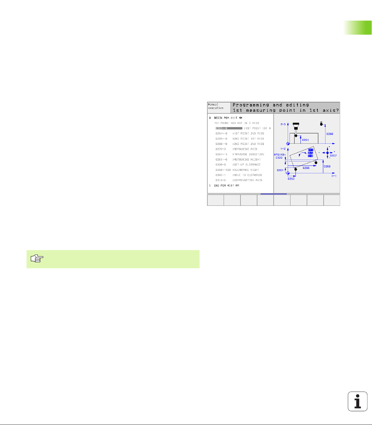
You can program the touch probe cycles in the Programming and
Editing operating mode via the TOUCH PROBE key. Like the most
recent fixed cycles, touch probe cycles use Q parameters with
numbers of 400 and above as transfer parameters. Parameters with
the same function that the TNC requires in several cycles always have
the same number: For example, Q260 is always assigned the
clearance height, Q261 the measuring height, etc.
To simplify programming, the TNC shows an illustration during cycle
definition. In the illustration, the parameter that needs to be entered is
highlighted (see figure at right).
1.1 General Information on Touch Probe Cycles
To improve clarity, the help illustrations sometimes omit
certain parameters.
HEIDENHAIN TNC 426, TNC 430 3
Page 16
Defining the touch probe cycle in the Programming and Editing
operation mode
UUUU The soft-key row shows all available touch probe
functions divided into groups.
UUUU Select the desired probe cycle, for example datum
setting. Digitizing cycles and cycles for automatic tool
measurement are available only if your machine has
been prepared for them.
UUUU Select a cycle, e.g. datum setting at pocket. The TNC
initiates the programming dialog and asks all required
input values. At the same time a graphic of the input
parameters is displayed in the right screen window.
The parameter that is asked for in the dialog prompt
is highlighted.
UUUU Enter all parameters requested by the TNC and
conclude each entry with the ENT key.
UUUU The TNC ends the dialog when all required data has
been entered.
Group of measuring cycles Soft key
Cycles for automatic measurement and compensation
of workpiece misalignment
Cycles for automatic datum setting
Example: NC blocks
5 TCH PROBE 410 DATUM INSIDE RECTAN.
Q321=+50 ;CENTER IN 1ST AXIS
Q322=+50 ;CENTER IN 2ND AXIS
Q323=60 ;1ST SIDE LENGTH
Q323=60 ;1ST SIDE LENGTH
Q324=20 ;2ND SIDE LENGTH
Q261=-5 ;MEASURING HEIGHT
Q320=0 ;SET-UP CLEARANCE
Q260=+20 ;CLEARANCE HEIGHT
Q301=0 ;TRAVERSE TO CLEAR HEIGHT
Q305=10 ;NO. IN TABLE
Q331=+0 ;DATUM
Q332=+0 ;DATUM
Cycles for automatic workpiece inspection
Automatic calibration cycle
1.1 General Information on Touch Probe Cycles
Cycles for digitizing with measuring touch probe
(option, not available for ISO)
Cycles for digitizing with measuring touch probe
(option, not available for ISO)
Cycles for automatic tool measurement (enabled by
the machine tool builder, not ISO)
4 1 Introduction
Page 17
1.2 Before You Start Working with
Touch Probe Cycles!
To make it possible to cover the widest possible range of applications,
machine parameters enable you to determine the behavior common
to all touch probe cycles:
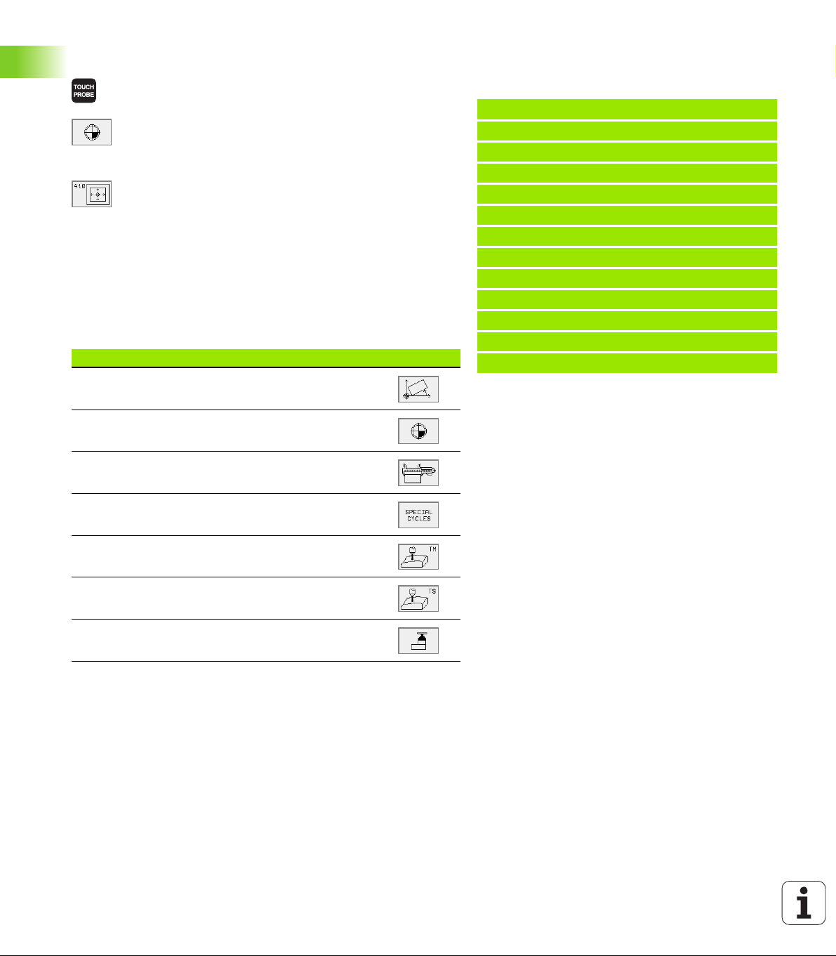
Maximum traverse to touch point: MP6130
If the stylus is not deflected within the path defined in MP6130, the
TNC outputs an error message.
Safety clearance to touch point: MP6140
In MP6140 you define how far from the defined (or calculated) touch
point the TNC is to pre-position the touch probe. The smaller the value
you enter, the more exactly must you define the touch point position.
In many touch probe cycles you can also define a setup clearance in
addition that is added to machine parameter 6140.
Orient the infrared touch probe to the
programmed probe direction: MP6165 (as
of 280 476-10)
To increase measuring accuracy, you can use MP 6165 = 1 to have an
infrared touch probe oriented in the programmed probe direction
before every probe process. In this way the stylus is always deflected
in the same direction.
Multiple measurement: MP6170
To increase measuring certainty, the TNC can run each probing
process up to three times in sequence. If the measured position
values differ too greatly, the TNC outputs an error message (the limit
value is defined in MP6171). With multiple measurement it is possible
to detect random errors, e.g., from contamination.
If the measured values lie within the confidence interval, the TNC
saves the mean value of the measured positions.
Confidence interval for multiple measurement: MP6171
In MP6171 you store the value by which the results may differ when
you make multiple measurements. If the difference in the measured
values exceeds the value in MP6171, the TNC outputs an error
message.
HEIDENHAIN TNC 426, TNC 430 5
1.2 Before You Start Working with Touch Probe Cycles!
Page 18
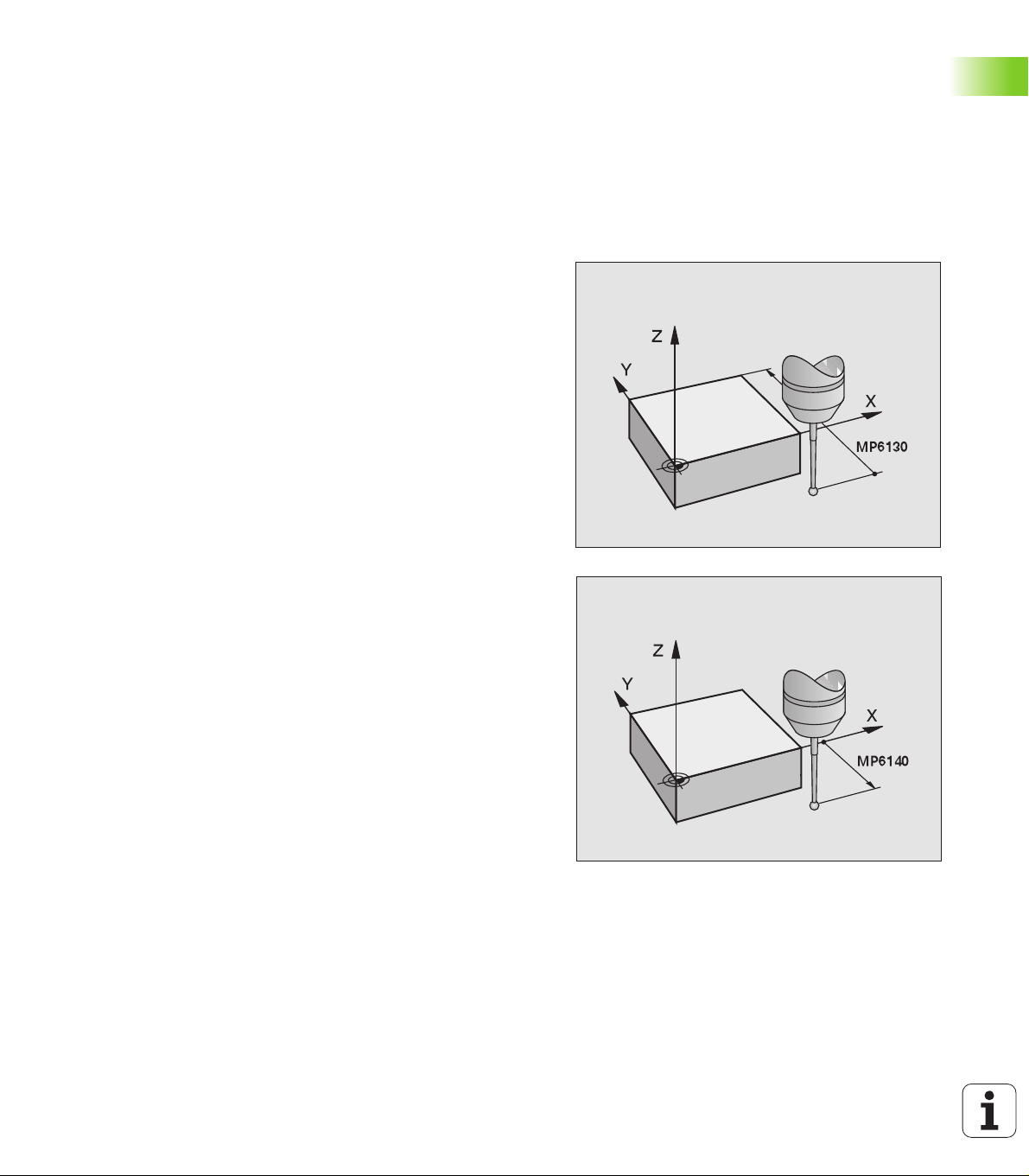
Touch trigger probe, probing feed rate: MP6120
In MP6120 you define the feed rate at which the TNC is to probe the
workpiece.
Touch trigger probe, rapid traverse for prepositioning: MP6150
In MP6150 you define the feed rate at which the TNC pre-positions the
touch probe, or positions it between measuring points.
Measuring touch probe, probing feed rate: MP6360
In MP6360 you define the feed rate at which the TNC is to probe the
workpiece.
Measuring touch probe, rapid traverse for prepositioning: MP6361
In MP6361 you define the feed rate at which the TNC pre-positions the
touch probe, or positions it between measuring points.
1.2 Before You Start Working with Touch Probe Cycles!
6 1 Introduction
Page 19
Running touch probe cycles
All touch probe cycles are DEF active. This means that the TNC runs
the cycle automatically as soon as the TNC executes the cycle
definition in the program run.
Make sure that at the beginning of the cycle the
compensation data (length, radius) from the calibrated
data or from the last TOOL CALL block are active
(selection via MP7411, see the User's Manual of the
respective control, “General User Parameters”).
NC software 280.476-xx
You can also run the touch probe cycles 410 to 418 during
an active basic rotation. Make sure, however, that the
basic rotation angle does not change when you use cycle
7 “zero shift from datum table” after the measuring cycle.
Touch probe cycles with a number greater than 400 position the touch
probe according to a positioning logic:
n If the current coordinate of the south pole of the stylus is less than
the coordinate of the clearance height (defined in the cycle), the TNC
retracts the touch probe in the probe axis to the clearance height
and then positions it in the working plane to the first starting
position.
n If the current coordinate of the south pole of the stylus is greater
than the coordinate of the clearance height, the TNC first positions
the probe in the working plane to the first starting position and then
moves it immediately to the measuring height in the touch probe
axis.
HEIDENHAIN TNC 426, TNC 430 7
1.2 Before You Start Working with Touch Probe Cycles!
Page 20

Page 21
2
Touch Probe Cycles in the Manual and Electronic Handwheel Modes
Page 22
2.1 Introduction
Overview
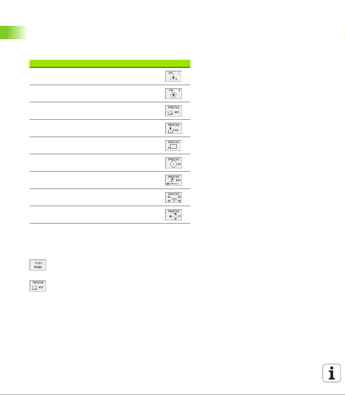
The following touch probe cycles are available in the manual mode:
Function Soft key
Calibrate the effective length
2.1 Introduction
Calibrate the effective radius
Measure a basic rotation using a line
Datum setting in any axis
Set the datum at a corner
Set the datum at a circle center
Measure a basic rotation using two holes/cylindrical
studs
Set the datum using four holes/cylindrical studs
Set the circle center using three holes/cylindrical studs
Selecting probe cycles
UUUU Select the Manual Operation or Electronic Handwheel mode of
operation.
UUUU To choose the touch probe functions, press the
TOUCH PROBE soft key. The TNC displays additional
soft keys—see table at right.
UUUU To select the probe cycle: press the appropriate soft
key, for example PROBING ROT, and the TNC
displays the associated menu.
10 2 Touch Probe Cycles in the Manual and Electronic Handwheel Modes
Page 23
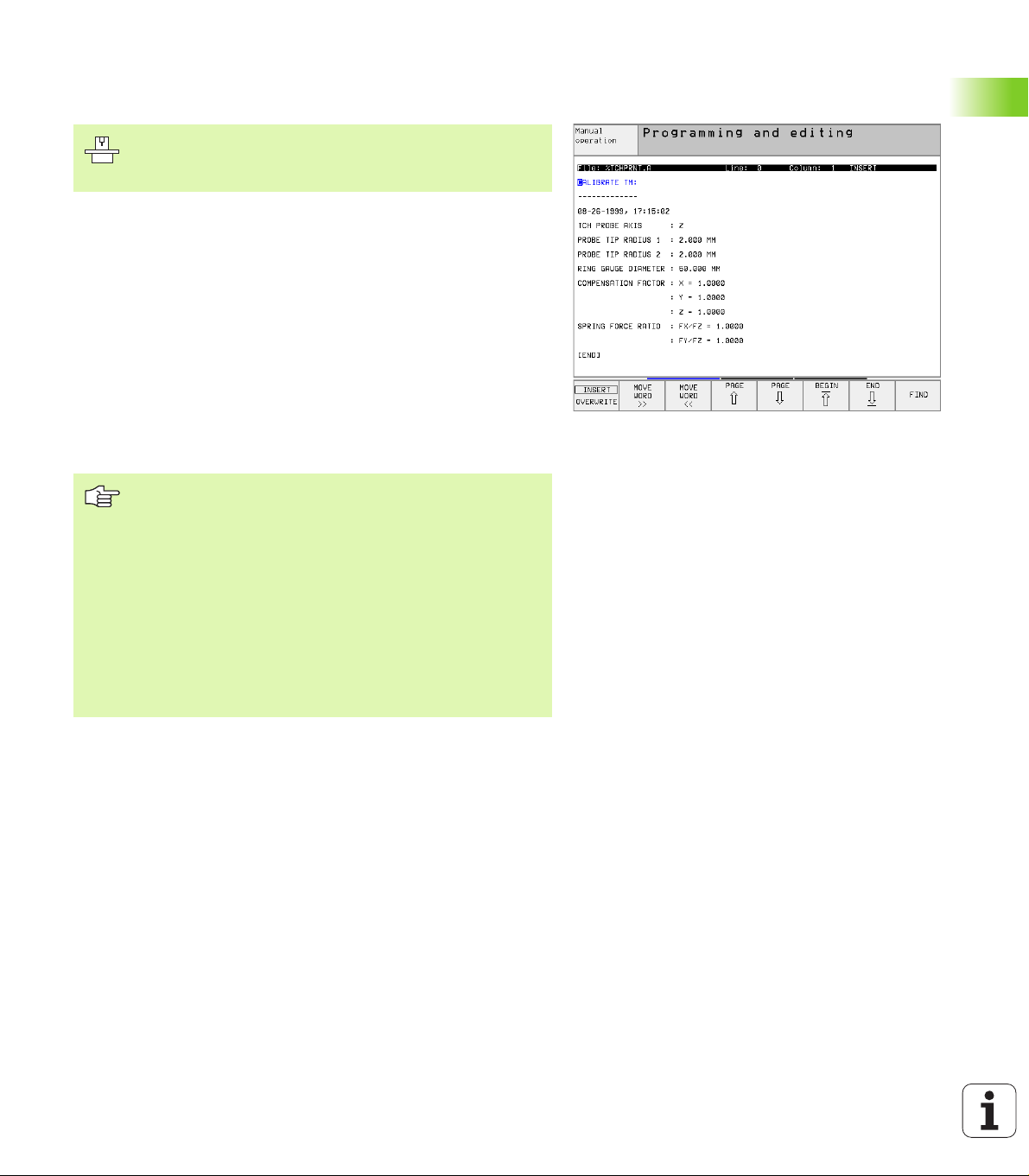
Recording Measured Values from the Probe Cycles
The TNC must be specially prepared by the machine tool
builder for use of this function. The machine tool manual
provides further information.
After executing any selected probe cycle, the TNC displays the soft
key PRINT. If you press this soft key, the TNC will record the current
values determined in the active probe cycle. You can then use the
PRINT function in the menu for setting the data interface (see the
User's Manual Chapter 12, “MOD Functions, Setting the Data
Interfaces”) to define whether the TNC is to
n print the measuring result,
n store the measuring results on the TNC’s hard disk, or
n store the measuring results on a PC.
If you store the measuring results, the TNC creates the ASCII file
%TCHPRNT.A. Unless you define a specific path and interface in the
interface configuration menu, the TNC will store the %TCHPRNT file
in the main directory TNC:\.
When you press the PRINT soft key, the %TCHPRNT.A
file must not be
active in the Programming and Editing mode of operation.
The TNC will otherwise display an error message.
The TNC stores the measured data in the %TCHPRNT.A
file only. If you execute several probe cycles in succession
and want to store the resulting measured data, you must
make a backup of the contents stored in %TCHPRNT.A
between the individual cycles by copying or renaming the
file.
Format and contents of the %TCHPRNT file are preset by
the machine tool builder.
2.1 Introduction
HEIDENHAIN TNC 426, TNC 430 11
Page 24
Writing the measured values from probe cycles in datum tables
This function is active only if you have datum tables active
on your TNC (bit 3 in machine parameter 7224.0 =0).
With the ENTER IN DATUM TABLE soft key, the TNC can write the
values measured during a probe cycle in a datum table:
UUUU Select any probe function.
2.1 Introduction
UUUU Enter the desired coordinates of the datum in the appropriate input
fields (depends on the touch probe cycle being run).
UUUU Enter the datum number in the datum number = input box.
UUUU Enter the name of the datum table (complete path) in the datum
table input box.
UUUU Press the soft key ENTER IN DATUM TABLE. The TNC displays
whether the data are to be transferred to the indicated datum table
as actual values or reference values.
If, in addition to the desired coordinate of the datum, you wish to enter
an incremental distance in the table, switch the soft key DISTANCE to
ON. The TNC then displays an additional input box for each axis, in
which you can enter the desired distance. The TNC then writes the
sum of the desired datum and its assigned distance into the table.
If immediately after probing you have used the probing
menu to reset the datum, do not write the probe values to
a datum table. The probe values saved by the TNC are
always based on the datum that was active at the time of
probing. Writing the probe values to a datum table would
result in incorrect entries.
12 2 Touch Probe Cycles in the Manual and Electronic Handwheel Modes
Page 25
2.2 Calibrating a Touch Trigger
Probe
Introduction
The touch probe must be calibrated in the following cases:
n Commissioning
n Stylus breakage
n Stylus exchange
n Change in the probe feed rate
n Irregularities caused, for example, when the machine heats up
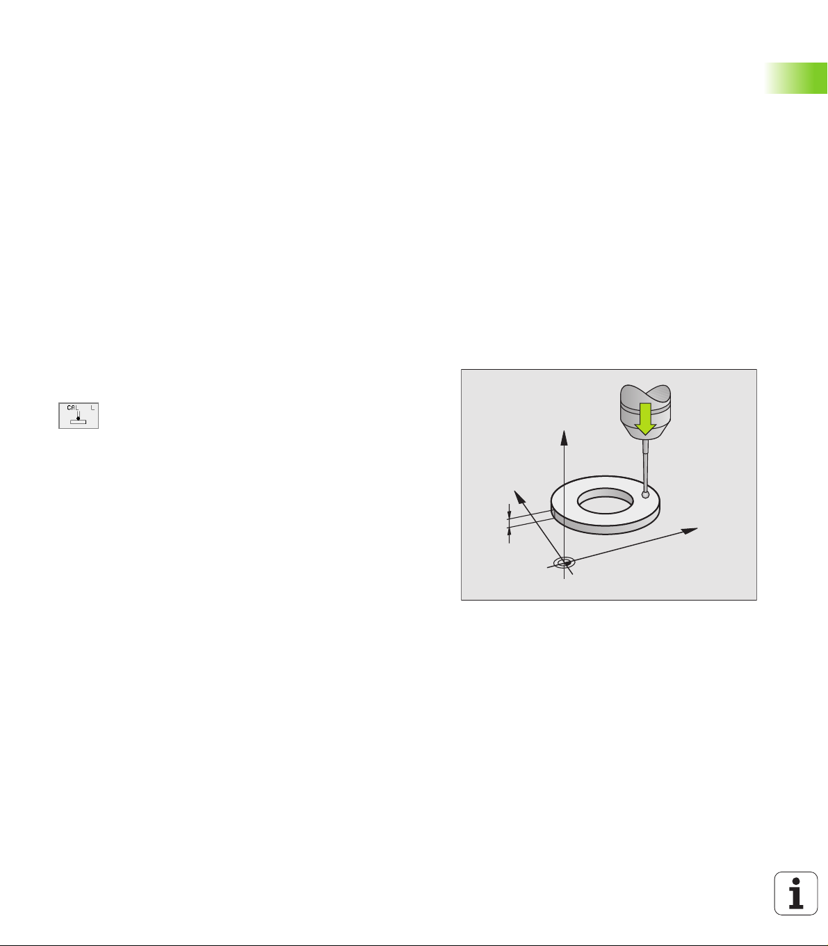
During calibration, the TNC finds the “effective” length of the stylus
and the “effective” radius of the ball tip. To calibrate the touch probe,
clamp a ring gauge of known height and known internal radius to the
machine table.
Calibrating the effective length
UUUU Set the datum in the spindle axis such that for the machine tool table
Z=0.
UUUU To select the calibration function for the touch probe
length, press the TOUCH PROBE and CAL L soft
keys. The TNC then displays a menu window with
four input fields.
UUUU Enter the tool axis (with the axis key).
UUUU Datum: Enter the height of the ring gauge.
UUUU The menu items Effective ball radius and Effective
length do not require input.
UUUU Move the touch probe to a position just above the ring
gauge.
UUUU To change the traverse direction (if necessary) press a
soft key or an arrow key.
UUUU To probe the upper surface of the ring gauge, press
the machine START button.
Z
2.2 Calibrating a Touch Trigger Probe
Y
5
X
HEIDENHAIN TNC 426, TNC 430 13
Page 26
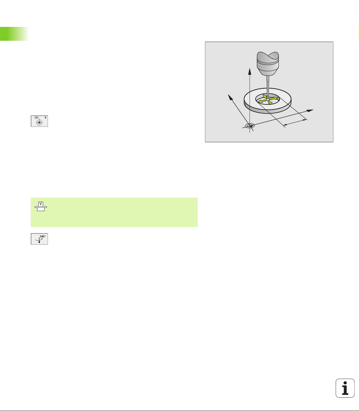
Calibrating the effective radius and compensating center misalignment
After the touch probe is inserted it normally needs to be aligned
exactly with the spindle axis. The misalignment is measured with this
calibration function and compensated electronically.
For this operation the TNC rotates the 3-D touch probe by 180°. The
rotation is initiated by a miscellaneous function that is set by the
machine tool builder in machine parameter 6160.
The center misalignment is measured after the effective ball tip radius
is calibrated.
UUUU In the Manual Operation mode, position the ball tip in the bore of the
ring gauge.
UUUU To select the calibration function for the ball-tip radius
and the touch probe center misalignment, press the
CAL R soft key.
UUUU Select the tool axis and enter the radius of the ring
gauge.
UUUU To probe the workpiece, press the machine START
button four times. The touch probe contacts a
position on the bore in each axis direction and
calculates the effective ball-tip radius.
2.2 Calibrating a Touch Trigger Probe
UUUU If you want to terminate the calibration function at this
point, press the ENDE soft key.
Z
Y
X
10
In order to be able to determine ball-tip center
misalignment, the TNC needs to be specially prepared by
the machine manufacturer. The machine tool manual
provides further information.
UUUU If you want to determine the ball-tip center
misalignment, press the180° soft key. The TNC
rotates the touch probe by 180°.
UUUU To probe the workpiece, press the machine START
button four times. The touch probe contacts a
position on the bore in each axis direction and
calculates the ball-tip center misalignment.
14 2 Touch Probe Cycles in the Manual and Electronic Handwheel Modes
Page 27
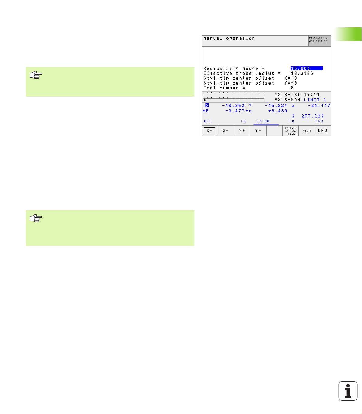
Displaying calibration values
The TNC stores the effective length and radius, as well as the center
misalignment, for use when the touch probe is needed again. You can
display the values on the screen with the soft keys CAL L and CAL R.
Storing calibration values in the TOOL.T tool table
This function is only available if bit 0 in machine parameter
7411 = 1 is set (activate touch probe data with TOOL CALL),
and tool table TOOL.T is active (machine parameter 7260
not equal to 0).
If you conduct measurements during program run, the compensation
data for the touch probe can be activated from the tool table via a TOOL
CALL. To store the calibration data in the TOOL.T tool table, enter the
tool number in the calibration menu (confirm with ENT) and then press
the ENTER R IN TOOL TABLE or the ENTER L IN TOOL TABLE soft
key.
Managing more than one block of calibrating data (as of NC software 280 476-xx)
To be able to use more than one block of calibration data, you must set
bit one in machine parameter 7411. The calibration data (length,
radius, center misalignment, and spindle angle) are then always saved
by the TNC in the tool table TOOL.T under a tool number that can be
selected in the calibration menu (see also User's Manual, section 5.2,
“Tool Data”).
2.2 Calibrating a Touch Trigger Probe
If you use this function, you must first activate the
corresponding tool number with a tool call before
executing a touch probe cycle, regardless of whether you
wish to run the touch probe cycle in automatic mode or
manual mode.
You can view and edit the calibration data in the calibration menu, but
you must make sure to write the changes back into the tool table by
pressing the ENTER R IN TOOL TABLE or ENTER L IN TOOL TABLE
soft key. The TNC does not write the calibration values into the table
automatically!
HEIDENHAIN TNC 426, TNC 430 15
Page 28
2.3 Calibrating a Measuring Touch
Probe
Introduction
If the TNC displays the error message "Stylus already in
contact," select the 3-D calibration menu and press the
RESET 3D soft key.
The measuring touch probe must be calibrated whenever
the machine parameters for 3-D touch probes are changed.
The effective length is calibrated in the same way as with
triggering touch probes. You must also enter tool radius R2
(corner radius).
With MP6321 you can define whether the TNC should
probe to find the stylus center.
The 3-D calibration cycle for measuring touch probes enables you to
measure a standard ring gauge fully automatically. (The standard ring
gauge is available from HEIDENHAIN). Fix the standard ring gauge to
the machine table with fixing clamps.
From the data measured during calibration, the TNC calculates the
spring rate of the touch probe, the stylus deflection and the stylus
center misalignment. At the end of the calibration cycle, the TNC
automatically stores these values in the input menu.
2.3 Calibrating a Measuring Touch Probe
Course of actions
UUUU In the Manual Operation mode, position the touch probe to a
position approximately in the center of the standard ring gauge and
set it to 180°.
UUUU To select the 3-D calibration cycle, press the 3D CAL
soft key
UUUU Enter the values for stylus radius 1 and stylus radius 2.
Enter the same value for stylus radius 1 and 2 if you
are using a stylus with ball tip. Enter different values
for stylus radius 1 and 2 if you are using a stylus with
a corner radius.
UUUU Diameter ring gauge: The diameter is engraved on the
standard ring gauge.
UUUU
To start the calibration cycle, press the machine START
button: The touch probe measures the standard ring
gauge in a programmed sequence of steps.
UUUU Rotate the touch probe to 0° as soon as the TNC asks
you to.
UUUU To start the calibration cycle once again to determine
center misalignment, press the machine START
button. The touch probe again measures the standard
ring gauge in a programmed sequence of steps.
16 2 Touch Probe Cycles in the Manual and Electronic Handwheel Modes
Page 29
Displaying calibration values
The compensation factors and force ratios are stored in the TNC for
later use whenever the measuring touch probe is needed.
You can display the stored values on the screen by pressing the 3D
CAL soft key.
Storing calibration values in the TOOL.T tool table
This function is only available if machine parameter 7411
= 1 is set (activate touch probe data with TOOL CALL), and
tool table TOOL.T is active (machine parameter 7260 not
equal to 0).
If you conduct measurements during program run, the compensation
data for the touch probe can be activated from the tool table via a TOOL
CALL. To store the calibration data in the TOOL.T tool table, enter the
tool number in the calibration menu (confirm with ENT) and then press
the ENTER R IN TOOL TABLE soft key.
The TNC stores the stylus radius 1 in the R column, and the stylus
radius 2 in the R2 column.
2.3 Calibrating a Measuring Touch Probe
HEIDENHAIN TNC 426, TNC 430 17
Page 30
2.4 Compensating Workpiece
Misalignment
Introduction
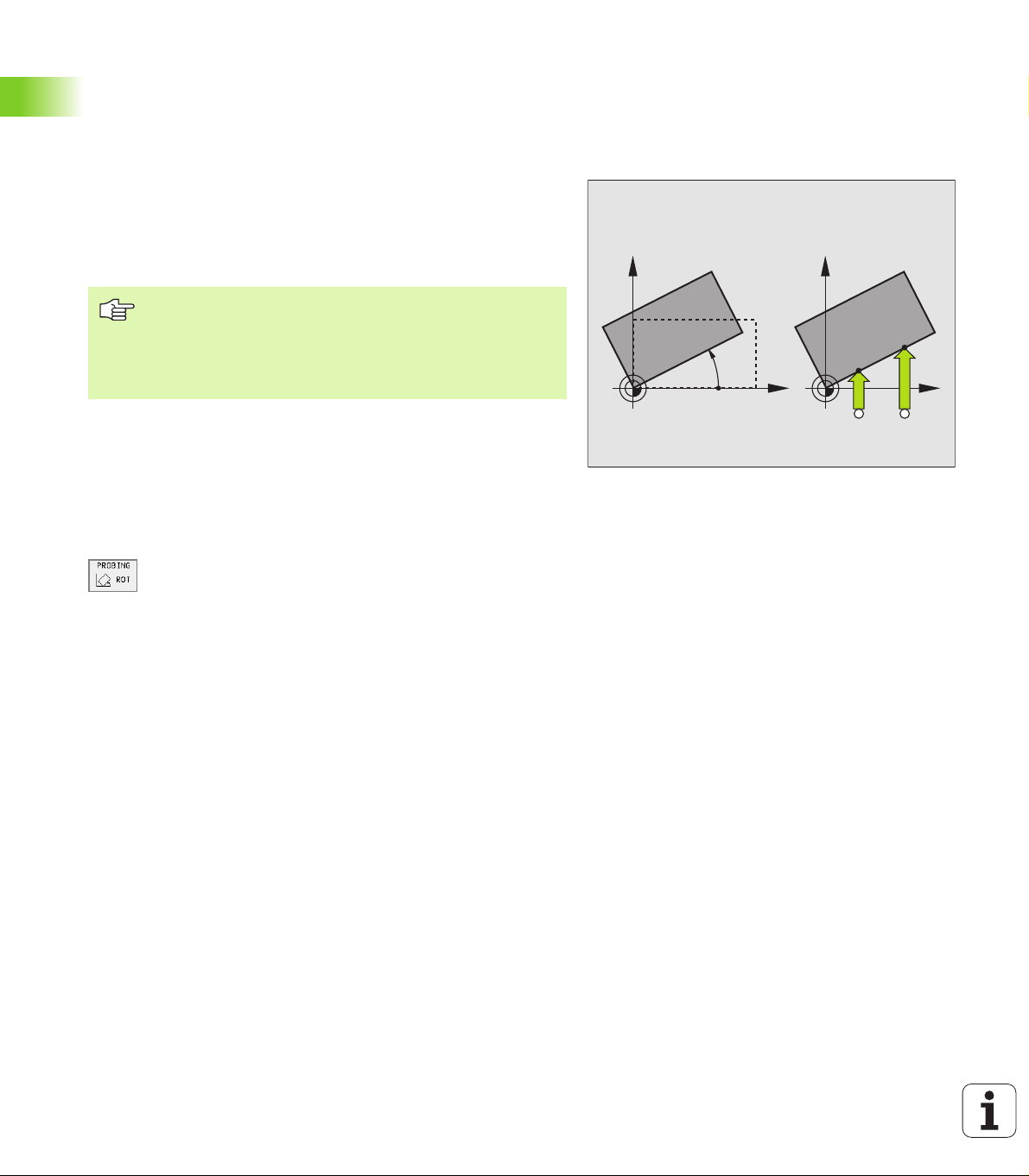
The TNC electronically compensates workpiece misalignment by
computing a “basic rotation.”
For this purpose, the TNC sets the rotation angle to the desired angle
with respect to the reference axis in the working plane. See figure at
right.
Select the probe direction perpendicular to the angle
reference axis when measuring workpiece misalignment.
To ensure that the basic rotation is calculated correctly
during program run, program both coordinates of the
working plane in the first positioning block.
Measuring the basic rotation
UUUU Select the probing function by pressing the PROBING
ROT soft key.
2.4 Compensating Workpiece Misalignment
The TNC saves the basic rotation in non-volatile memory. The basic
rotation is effective for all subsequent program runs and graphic
simulation.
UUUU Position the ball tip at a starting position near the first
touch point.
UUUU Select the probe direction perpendicular to the angle
reference axis: Select the axis by soft key.
UUUU To probe the workpiece, press the machine START
button.
UUUU Position the ball tip at a starting position near the
second touch point.
UUUU To probe the workpiece, press the machine START
button.
Y
PA
Y
X
A B
X
18 2 Touch Probe Cycles in the Manual and Electronic Handwheel Modes
Page 31

Displaying a basic rotation
The angle of the basic rotation appears after ROTATION ANGLE
whenever PROBING ROT is selected. The TNC also displays the
rotation angle in the additional status display (STATUS POS.).
In the status display a symbol is shown for a basic rotation whenever
the TNC is moving the axes according to a basic rotation.
Cancel a basic rotation
UUUU Select the probing function by pressing the PROBING ROT soft key.
UUUU Enter a rotation angle of zero and confirm with the ENT key.
UUUU To terminate the probe function, press the END key.
HEIDENHAIN TNC 426, TNC 430 19
2.4 Compensating Workpiece Misalignment
Page 32

2.5 Setting the Datum with a 3-D
Touch Probe
Introduction
The following functions are available for setting the datum on an
aligned workpiece:
n Datum setting in any axis with PROBING POS
n Defining a corner as datum with PROBING P
n Setting the datum at a circle center with PROBING CC
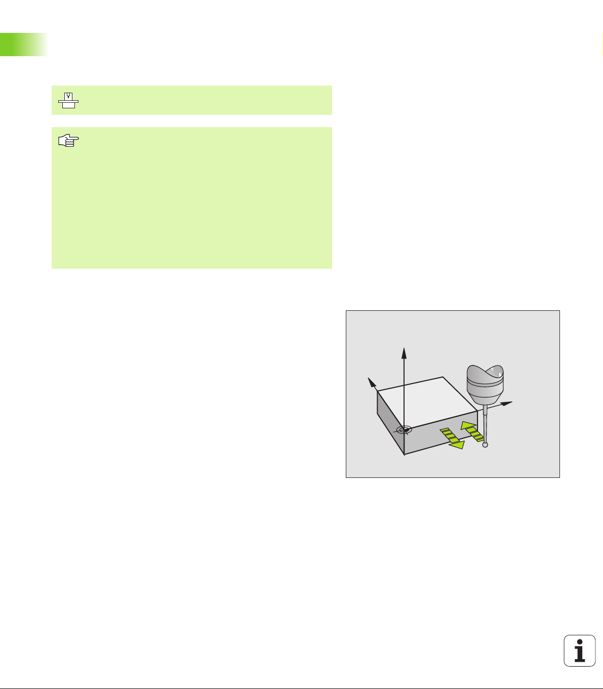
To set the datum in any axis (see figure at right)
UUUU Select the probing function by pressing the PROBING
POS soft key.
UUUU Move the touch probe to a starting position near the
touch point.
UUUU Select the probe axis and direction in which you wish
to set the datum, such as Z in direction Z–. Selection
is made via soft keys.
UUUU To probe the workpiece, press the machine START
button.
UUUU Datum: Enter the nominal coordinate and confirm your
entry with ENT.
Z
Y
X
2.5 Setting the Datum with a 3-D Touch Probe
20 2 Touch Probe Cycles in the Manual and Electronic Handwheel Modes
Page 33

Corner as datum—using points that were
already probed for a basic rotation (see figure at
right)
UUUU To select the probe function, press ANTASTEN P.
UUUU Touch points of basic rotation ?: Press ENT to transfer
the touch point coordinates to memory.
UUUU Position the touch probe at a starting position near the
first touch point of the side that was not probed for
basic rotation.
UUUU Select the probe direction with a soft key.
UUUU To probe the workpiece, press the machine START
button.
UUUU Position the touch probe near the second touch point
on the same side.
UUUU To probe the workpiece, press the machine START
button.
UUUU Datum: Enter both datum coordinates into the menu
window, and confirm your entry with the ENT key.
UUUU To terminate the probe function, press the END key.
Corner as datum—without using points that
were already probed for a basic rotation
Y=?
Y
P
X=?
Y
P
X
X
UUUU To select the probe function, press PROBING P.
UUUU Touch points of basic rotation?: Press NO ENT to ignore the
previous touch points. (The dialog question only appears if a basic
rotation was made previously.)
UUUU Probe both workpiece sides twice.
UUUU Enter the coordinates of the datum and confirm your entry with ENT.
UUUU To terminate the probe function, press the END key.
HEIDENHAIN TNC 426, TNC 430 21
2.5 Setting the Datum with a 3-D Touch Probe
Page 34

Circle center as datum
With this function, you can set the datum at the center of bore holes,
circular pockets, cylinders, studs, circular islands, etc.
Inside circle
The TNC automatically probes the inside wall in all four coordinate axis
directions.
For incomplete circles (circular arcs) you can choose the appropriate
probing direction.
UUUU Position the touch probe approximately in the center of the circle.
UUUU To select the probe function, press ANTASTEN CC.
UUUU To probe the workpiece, press the machine START
button four times. The touch probe touches four
points on the inside of the circle.
UUUU If you are probing to find the stylus center (only
available on machines with spindle orientation,
depending on MP6160), press the 180° soft key and
probe another four points on the inside of the circle.
UUUU If you are not probing to find the stylus center, press
the END key.
UUUU Datum: Enter both circle center coordinates into the
menu window, and confirm your entry with ENT.
UUUU To terminate the probe function, press the END key.
Y
Y+
X+X–
Y–
X
Y
Y–
X+
Outside circle
UUUU Position the touch probe at the starting position for the first touch
point outside of the circle.
UUUU Select the probe direction with a soft key.
2.5 Setting the Datum with a 3-D Touch Probe
UUUU To probe the workpiece, press the machine START button.
UUUU Repeat the probing process for the remaining three points. See
figure at lower right.
UUUU Enter the coordinates of the datum and confirm your entry with ENT.
After the probing procedure is completed, the TNC displays the
coordinates of the circle center and the circle radius PR.
Y+
X–
X
22 2 Touch Probe Cycles in the Manual and Electronic Handwheel Modes
Page 35

Setting datum points using holes/cylindrical studs
A second soft-key row provides soft keys for using holes or cylindrical
studs to set datums.
Define whether a hole or stud is to be probed
UUUU Select the probing functions with the TOUCH PROBE,
shift the soft-key row.
UUUU Select the probing function: For example, press the
PROBING ROT soft key.
UUUU Select holes or cylindrical studs: the selected element
appears in a box
Probing holes
Pre-position the touch probe approximately in the center of the hole.
After you have pressed the external START key, the TNC automatically
probes four points on the wall of the hole.
Move the touch probe to the next hole and have the TNC repeat the
probing procedure until all the holes have been probed to set datums.
Probing cylindrical studs
Position the ball tip at a starting position near the first touch point of
the stud. Select the probing direction by soft key and press the
machine START button to start probing. Perform the above procedure
four times.
Overview
Cycle Soft key
Basic rotation using 2 holes:
The TNC measures the angle between the line
connecting the centers of two holes and a nominal
position (angle reference axis).
Datum using 4 holes:
The TNC calculates the intersection of the line
connecting the first two probed holes with the line
connecting the last two probed holes. You need to
probe diagonally opposite holes one after another (as
shown on the soft key), as otherwise the datum
calculated by the TNC will be incorrect.
Circle center using 3 holes:
The TNC calculates a circle that intersects the centers
of all three holes, and finds the center.
2.5 Setting the Datum with a 3-D Touch Probe
HEIDENHAIN TNC 426, TNC 430 23
Page 36

2.6 Measuring Workpieces with a
3-D Touch Probe
Introduction
You can also use the touch probe in the Manual and Electronic
Handwheel operating modes to make simple measurements on the
workpiece. With a 3-D touch probe you can determine:
n position coordinates, and from them,
n dimensions and angles on the workpiece.
To find the coordinate of a position on an aligned workpiece:
UUUU Select the probing function by pressing the PROBING
POS soft key.
UUUU Move the touch probe to a starting position near the
touch point.
UUUU Select the probe direction and axis of the coordinate.
Use the corresponding soft keys for selection.
UUUU To probe the workpiece, press the machine START
button.
The TNC shows the coordinates of the touch point as datum.
Finding the coordinates of a corner in the working plane
Find the coordinates of the corner point: See “Corner as datum—
without using points that were already probed for a basic rotation,”
page 21. The TNC displays the coordinates of the probed corner as
2.6 Measuring Workpieces with a 3-D Touch Probe
datum.
24 2 Touch Probe Cycles in the Manual and Electronic Handwheel Modes
Page 37

Measuring workpiece dimensions
UUUU Select the probing function by pressing the PROBING
POS soft key.
UUUU Position the touch probe at a starting position near the
first touch point A.
UUUU Select the probing direction with a soft key.
UUUU To probe the workpiece, press the machine START
button.
UUUU If you will need the current datum later, write down
the value that appears in the datum display.
UUUU Datum: Enter “0”.
UUUU To terminate the dialog, press the END key.
UUUU Select the probing function by pressing the PROBING
POS soft key.
UUUU Position the touch probe at a starting position near the
second touch point B
UUUU Select the probe direction with the soft keys: Same
axis but from the opposite direction.
UUUU To probe the workpiece, press the machine START
button.
The value displayed as datum is the distance between the two points
on the coordinate axis.
Z
Y
B
A
X
l
To return to the datum that was active before the length
measurement:
UUUU Select the probing function by pressing the PROBING POS soft key.
UUUU Probe the first touch point again.
UUUU Set the datum to the value that you wrote down previously.
UUUU To terminate the dialog, press the END key.
Measuring angles
You can use the 3-D touch probe to measure angles in the working
plane. You can measure
n the angle between the angle reference axis and a workpiece side, or
n the angle between two sides.
The measured angle is displayed as a value of maximum 90°.
HEIDENHAIN TNC 426, TNC 430 25
2.6 Measuring Workpieces with a 3-D Touch Probe
Page 38

To find the angle between the angle reference axis and a side of the workpiece
UUUU Select the probing function by pressing the PROBING
ROT soft key.
UUUU Rotation angle: If you will need the current basic
rotation later, write down the value that appears
under Rotation angle.
UUUU Make a basic rotation with the side of the workpiece
(see “Compensating Workpiece Misalignment” on
page 18).
UUUU Press the PROBING ROT soft key to display the angle
between the angle reference axis and the side of the
workpiece as the rotation angle.
UUUU Cancel the basic rotation, or restore the previous basic
rotation:
UUUU This is done by setting the rotation angle to the value
that you wrote down previously.
PA
To measure the angle between two workpiece sides:
UUUU Select the probing function by pressing the PROBING ROT soft key.
UUUU Rotation angle: If you will need the current basic rotation later, write
down the value that appears under Rotation angle.
UUUU Make a basic rotation with the side of the workpiece (see
“Compensating Workpiece Misalignment” on page 18).
UUUU Probe the second side as for a basic rotation, but do not set the
rotation angle to zero!
UUUU Press the PROBING ROT soft key to display the angle PA between
the two sides as the rotation angle.
UUUU Cancel the basic rotation, or restore the previous basic rotation by
setting the rotation angle to the value that you wrote down
previously.
2.6 Measuring Workpieces with a 3-D Touch Probe
100
Y
–10
Z
L?
α?
X
α?
100
26 2 Touch Probe Cycles in the Manual and Electronic Handwheel Modes
Page 39

3
Touch Probe Cycles for Automatic Workpiece Inspection
HEIDENHAIN TNC 426, TNC 430 27
Page 40

3.1 Measuring Workpiece
Misalignment
Overview
The TNC provides five cycles that enable you to measure and
compensate workpiece misalignment. In addition, you can reset a
basic rotation with Cycle 404.
Cycle Soft key
400 BASIC ROTATION Automatic measurement
using two points. Compensation via basic
rotation.
401 ROT OF 2 HOLES Automatic measurement
using two holes. Compensation via basic
rotation.
402 ROT OF 2 STUDS Automatic measurement
using two studs. Compensation via basic
rotation.
403 ROT IN ROTARY AXIS Automatic
measurement using two points. Compensation
via basic rotation.
405 ROT IN C AXIS Automatic alignment of an
angular offset between a hole center and the
3.1 Measuring Workpiece Misalignment
positive Y axis. Compensation via table rotation.
404 SET BASIC ROTATION Setting any basic
rotation
Characteristics common to all touch probe cycles for measuring workpiece misalignment
For the cycles 400, 401 and 402 you can define through parameter
Q307 Default setting for basic rotation whether the
measurement result is to be corrected by a known angle a (see figure
at right). This enables you to measure the basic rotation against any
straight line 1 of the workpiece and to establish the reference to the
actual 0° direction 2.
28 3 Touch Probe Cycles for Automatic Workpiece Inspection
1
2
Page 41

BASIC ROTATION (touch probe cycle 400, ISO: G400)
Touch probe cycle 400 determines a workpiece misalignment by
measuring two points, which must lie on a straight surface. With the
basic rotation function the TNC compensates the measured value
(See also “Compensating Workpiece Misalignment” on page 18).
1 The TNC positions the touch probe to the starting points at rapid
traverse (value from MP6150 or MP6361) following the positioning
logic (see “Running touch probe cycles” on page 7) to the
programmed starting point 1. The TNC offsets the touch probe by
the safety clearance in the direction opposite the defined traverse
direction.
2 Then the touch probe moves to the entered measuring height and
probes the first touch point at the probing feed rate (MP6120 or
MP6360).
3 Then the touch probe moves to the next starting position 2 and
probes the second position.
4 The TNC returns the touch probe to the clearance height and
performs the basic rotation.
Before programming, note the following:
Before a cycle definition you must have programmed a
tool call to define the touch probe axis.
The TNC will reset an active basic rotation at the beginning
of the cycle.
1
2
3.1 Measuring Workpiece Misalignment
HEIDENHAIN TNC 426, TNC 430 29
Page 42

UUUU First measuring point in the 1st axis Q263
(absolute): coordinate of the first touch point in the
reference axis of the working plane.
UUUU First measuring point in the 2nd axis Q264
(absolute): coordinate of the first touch point in the
minor axis of the working plane.
UUUU Second measuring point in the 1st axis Q265
(absolute): coordinate of the second touch point in the
reference axis of the working plane
UUUU Second measuring point in the 2nd axis Q266
(absolute): coordinate of the second touch point in the
minor axis of the working plane
UUUU Measuring axis Q272: axis in the working plane in
which the measurement is to be made:
1: Reference axis = measuring axis
2: Minor axis = measuring axis
UUUU Traverse direction 1 Q267: direction in which the
probe is to approach the workpiece:
-1: Negative traverse direction
+1: Positive traverse direction
UUUU Measuring height in the touch probe axis Q261
(absolute): coordinate of the ball tip center (= touch
point) in the touch probe axis in which the
measurement is to be made.
UUUU Setup clearance Q320 (incremental): additional
3.1 Measuring Workpiece Misalignment
distance between measuring point and ball tip. Q320
is added to MP6140.
UUUU Clearance height Q260 (absolute): coordinate in the
touch probe axis at which no collision between tool
and workpiece (fixtures) can occur.
UUUU Traversing to clearance height Q301: definition of
how the touch probe is to move between the
measuring points:
0: Move at measuring height between measuring
points
1:
Move at clearance height between measuring
points
UUUU Default setting for basic rotation Q307
(absolute): If the misalignment is to be measured
against a straight line other than the reference axis,
enter the angle of this reference line. The TNC will
then calculate the difference between the measured
value and the angle of the reference line for the basic
rotation.
Y
Q272=2
Q266
Q264
Q263
–
Q265
Example: NC blocks
5 TCH PROBE 400 BASIC ROTATION
Q263=+10 ;1ST POINT 1ST AXIS
Q264=+3.5 ;1ST POINT 2ND AXIS
Q265=+25 ;2ND POINT 1ST AXIS
Q266=+2 ;2ND POINT 2ND AXIS
Q272=2 ;MEASURING AXIS
Q267=+1 ;TRAVERSE DIRECTION
Q261=-5 ;MEASURING HEIGHT
Q320=0 ;SET-UP CLEARANCE
Q260=+20 ;CLEARANCE HEIGHT
Q301=0 ;TRAVERSE TO CLEAR HEIGHT
Q307=+0 ;PRESET BASIC ROTATION
+
Q267
–
MP6140
+
Q320
X
Q272=1
+
30 3 Touch Probe Cycles for Automatic Workpiece Inspection
Page 43

BASIC ROTATION from two holes (touch probe cycle 401, ISO: G401)
The touch probe cycle 401 measures the centers of two holes. Then
the TNC calculates the angle between the reference axis in the
working plane and the line connecting the two hole centers. With the
basic rotation function the TNC compensates the calculated value
(See also “Compensating Workpiece Misalignment” on page 18).
1 Following the positioning logic (see “Running touch probe cycles”
on page 7), the TNC positions the touch probe at rapid traverse
(value from MP6150 or MP6361) to the point entered as center of
the first hole 1.
2 Then the probe moves to the entered measuring height and
probes four points to find the first hole center.
3 The touch probe returns to the clearance height and then to the
position entered as center of the second hole 2.
4 The TNC moves the touch probe to the entered measuring height
and probes four points to find the second hole center.
5 Then the TNC returns the touch probe to the clearance height and
performs the basic rotation.
Before programming, note the following:
Before a cycle definition you must have programmed a
tool call to define the touch probe axis.
The TNC will reset an active basic rotation at the beginning
of the cycle.
2
1
3.1 Measuring Workpiece Misalignment
HEIDENHAIN TNC 426, TNC 430 31
Page 44

UUUU First hole: Center in 1st axis Q268 (absolute):
center of the first hole in the reference axis of the
working plane.
UUUU First hole: Center in 2nd axis Q269 (absolute):
center of the first hole in the minor axis of the working
plane.
UUUU Second hole: Center in 1st axis Q270 (absolute):
center of the second hole in the reference axis of the
working plane.
UUUU Second hole: Center in 2nd axis Q271 (absolute):
center of the second hole in the minor axis of the
working plane.
UUUU Measuring height in the touch probe axis Q261
(absolute): coordinate of the ball tip center (= touch
point) in the touch probe axis in which the
measurement is to be made.
UUUU Clearance height Q260 (absolute): coordinate in the
touch probe axis at which no collision between tool
and workpiece (fixtures) can occur.
UUUU Default setting for basic rotation Q307
(absolute): If the misalignment is to be measured
against a straight line other than the reference axis,
enter the angle of this reference line. The TNC will
then calculate the difference between the measured
value and the angle of the reference line for the basic
3.1 Measuring Workpiece Misalignment
rotation.
Example: NC blocks
5 TCH PROBE 401 ROT OF 2 HOLES
Q268=-37 ;1ST CENTER 1ST AXIS
Q269=+12 ;1ST CENTER 2ND AXIS
Q270=+75 ;2ND CENTER 1ST AXIS
Q271=+20 ;2ND CENTER 2ND AXIS
Q261=-5 ;MEASURING HEIGHT
Q260=+20 ;CLEARANCE HEIGHT
Q307=+0 ;PRESET BASIC ROT.
32 3 Touch Probe Cycles for Automatic Workpiece Inspection
Page 45

BASIC ROTATION over two studs (touch probe cycle 402, ISO: G402)
The touch probe cycle 402 measures the centers of two studs. Then
the TNC calculates the angle between the reference axis in the
working plane and the line connecting the two stud centers. With the
basic rotation function the TNC compensates the calculated value
(See also “Compensating Workpiece Misalignment” on page 18).
1 Following the positioning logic (see “Running touch probe cycles”
on page 7), the TNC positions the touch probe in rapid traverse
(value from MP6150 or MP6361) to the starting point for probing
the first stud 1.
2 Then the probe moves to the entered measuring height 1 and
probes four points to find the center of the first stud. The touch
probe moves on a circular arc between the touch points, each of
which is offset by 90°.
3 The touch probe returns to the clearance height and then to the
starting point for probing 5 the second stud.
4 The TNC moves the touch probe to the entered measuring height
2 and probes four points to find the center of the second stud.
5 Then the TNC returns the touch probe to the clearance height and
performs the basic rotation.
Before programming, note the following:
Before a cycle definition you must have programmed a
tool call to define the touch probe axis.
The TNC will reset an active basic rotation at the beginning
of the cycle.
Y
5
1
X
3.1 Measuring Workpiece Misalignment
HEIDENHAIN TNC 426, TNC 430 33
Page 46

UUUU First stud: Center in 1st axis Q268 (absolute):
center of the first stud in the reference axis of the
working plane.
UUUU First stud: Center in 2nd axis Q269 (absolute):
center of the first stud in the minor axis of the
working plane.
UUUU Diameter of stud 1 Q313: approximate diameter of
the 1st stud. Enter a value that is more likely to be too
large than too small.
UUUU Measuring height 1 in the probe axis Q261
(absolute): coordinate of the ball tip center (= touch
point in the touch probe axis) at which stud 1 is to be
measured.
UUUU Second stud: Center in 1st axis Q270 (absolute):
center of the second stud in the reference axis of the
working plane.
UUUU Second stud: Center in 2nd axis Q271 (absolute):
center of the second stud in the minor axis of the
working plane.
UUUU Diameter of stud 2 Q314: approximate diameter of
the 2nd stud. Enter a value that is more likely to be
too large than too small.
UUUU Measuring height 2 in the probe axis Q315
(absolute): coordinate of the ball tip center (= touch
point in the touch probe axis) at which stud 2 is to be
3.1 Measuring Workpiece Misalignment
measured.
UUUU Setup clearance Q320 (incremental): additional
distance between measuring point and ball tip. Q320
is added to MP6140.
UUUU Clearance height Q260 (absolute): coordinate in the
touch probe axis at which no collision between tool
and workpiece (fixtures) can occur.
UUUU Traversing to clearance height Q301: definition of
how the touch probe is to move between the
measuring points:
0: Move at measuring height between measuring
points
1: Move at clearance height between measuring
points
UUUU Default setting for basic rotation Q307
(absolute): If the misalignment is to be measured
against a straight line other than the reference axis,
enter the angle of this reference line. The TNC will
then calculate the difference between the measured
value and the angle of the reference line for the basic
rotation.
Y
Q271
Q269
Q313
Q268 Q270
Z
Q261
Q315
MP6140
+
Q320
Example: NC blocks
5 TCH PROBE 402 ROT OF 2 STUDS
Q268=-37 ;1ST CENTER 1ST AXIS
Q269=+12 ;1ST CENTER 2ND AXIS
Q313=60 ;DIAMETER OF STUD 1
Q261=-5 ;MEASURING HEIGHT 1
Q270=+75 ;2ND CENTER 1ST AXIS
Q271=+20 ;2ND CENTER 2ND AXIS
Q314=60 ;DIAMETER STUD 2
Q315=-5 ;MEASURING HEIGHT 2
Q320=0 ;SET-UP CLEARANCE
Q260=+20 ;CLEARANCE HEIGHT
Q301=0 ;TRAVERSE TO CLEAR HEIGHT
Q307=+0 ;PRESET BASIC ROT.
Q314
X
Q260
X
34 3 Touch Probe Cycles for Automatic Workpiece Inspection
Page 47

BASIC ROTATION compensation via rotary axis (touch probe cycle 403, ISO: G403)
Touch probe cycle 403 determines a workpiece misalignment by
measuring two points, which must lie on a straight surface. The TNC
compensates the misalignment by rotating the A, B or C axis. The
workpiece can be clamped in any position on the rotary table.
1 The TNC positions the touch probe to the starting points at rapid
traverse (value from MP6150 or MP6361) following the positioning
logic (see “Running touch probe cycles” on page 7) to the
programmed starting point 1. The TNC offsets the touch probe by
the safety clearance in the direction opposite the defined traverse
direction.
2 Then the touch probe moves to the entered measuring height and
probes the first touch point at the probing feed rate (MP6120 or
MP6360).
3 Then the touch probe moves to the next starting position 2 and
probes the second position.
4 The TNC returns the touch probe to the clearance height and
moves the rotary axis, which was defined in the cycle, by the
measured value.
Before programming, note the following:
Before a cycle definition you must have programmed a
tool call to define the touch probe axis.
2
11
3.1 Measuring Workpiece Misalignment
HEIDENHAIN TNC 426, TNC 430 35
Page 48

UUUU First measuring point in the 1st axis Q263
(absolute): coordinate of the first touch point in the
reference axis of the working plane.
UUUU First measuring point in the 2nd axis Q264
(absolute): coordinate of the first touch point in the
minor axis of the working plane.
UUUU Second measuring point in the 1st axis Q265
(absolute): coordinate of the second touch point in the
reference axis of the working plane
UUUU Second measuring point in the 2nd axis Q266
(absolute): coordinate of the second touch point in the
minor axis of the working plane
UUUU Measuring axis Q272: axis in which the measurement
is to be made:
1: Reference axis = measuring axis
2: Minor axis = measuring axis
3: Touch probe axis = measuring axis
UUUU Traverse direction 1 Q267: direction in which the
probe is to approach the workpiece:
-1: Negative traverse direction
+1: Positive traverse direction
UUUU Measuring height in the touch probe axis Q261
(absolute): coordinate of the ball tip center (= touch
point) in the touch probe axis in which the
measurement is to be made.
3.1 Measuring Workpiece Misalignment
UUUU Setup clearance Q320 (incremental): additional
distance between measuring point and ball tip. Q320
is added to MP6140.
UUUU Clearance height Q260 (absolute): coordinate in the
touch probe axis at which no collision between tool
and workpiece (fixtures) can occur.
UUUU Traversing to clearance height Q301: definition of
how the touch probe is to move between the
measuring points:
0: Move at measuring height between measuring
points
1: Move at clearance height between measuring
points
UUUU Axis for compensation motion Q312: assignment of
the rotary axis in which the TNC is to compensate the
measured misalignment:
4: Compensate misalignment with rotary axis A
5: Compensate misalignment with rotary axis B
6: Compensate misalignment with rotary axis C
Y
Q272=2
–
A
B
C
Q266
Q264
Q263
Example: NC blocks
5 TCH PROBE 403 ROT IN C-AXIS
Q263=+0 ;1ST POINT 1ST AXIS
Q264=+0 ;1ST POINT 2ND AXIS
Q265=+20 ;2ND POINT 1ST AXIS
Q266=+30 ;2ND POINT 2ND AXIS
Q272=1 ;MEASURING AXIS
Q267=+1 ;TRAVERSE DIRECTION
Q261=-5 ;MEASURING HEIGHT
Q320=0 ;SET-UP CLEARANCE
Q260=+20 ;CLEARANCE HEIGHT
Q301=0 ;TRAVERSE TO CLEAR HEIGHT
Q312=6 ;COMPENSATION AXIS
Q265
+
Q267
–
MP6140
+
Q320
X
Q272=1
+
36 3 Touch Probe Cycles for Automatic Workpiece Inspection
Page 49

SET BASIC ROTATION (touch probe cycle 404,
ISO: G404, available as of NC software
280 474-xx)
With touch probe cycle 404 you can set any basic rotation
automatically during program run. This cycle is intended primarily for
resetting a previous basic rotation.
UUUU Preset value for basic rotation: Angular value at
which the basic rotation is to be set.
Example: NC blocks
5 TCH PROBE 404 BASIC ROTATION
307=+0 ;PRESET BASIC ROTATION
3.1 Measuring Workpiece Misalignment
HEIDENHAIN TNC 426, TNC 430 37
Page 50

Compensating workpiece misalignment by rotating the C axis (touch probe cycle 405, ISO: G405, available as of NC software 280 474-xx)
With touch probe cycle 405 you can measure
n the angular offset between the positive Y axis of the active
coordinate system and the center of a hole, or
n the angular offset between the nominal position and the actual
position of a hole center.
The TNC compensates the misalignment by rotating the C axis. The
workpiece can be clamped in any position on the rotary table, but the
Y coordinate of the hole must be positive. If you measure the angular
misalignment of the hole with touch probe axis Y (horizontal position
of the hole), it may be necessary to conduct the cycle more than once
because the measuring strategy causes an inaccuracy of approx. 1%
of the misalignment.
1 The TNC positions the touch probe to the starting points at rapid
traverse (value from MP6150 or MP6361) following the positioning
logic (see “Running touch probe cycles” on page 7) to the starting
point 1. The TNC calculates the probe starting points from the data
in the cycle and the safety clearance from MP6140.
2 Then the touch probe moves to the entered measuring height and
probes the first touch point at the probing feed rate (MP6120 or
MP6360). The TNC derives the probing direction automatically
from the programmed starting angle.
3 Then the touch probe moves in a circular arc either at measuring
3.1 Measuring Workpiece Misalignment
height or at clearance height to the next starting point 2 and probes
the second touch point.
4 The TNC positions the probe to starting point 3 and then to starting
point 4 to probe the third and fourth touch points and positions the
touch probe on the hole centers measured.
5 Finally the TNC returns the touch probe to the clearance height and
aligns the workpiece by rotating the table. The TNC rotates the
rotary table so that the hole center after compensation lies in the
direction of the positive Y axis, or on the nominal position of the
hole center—both with a vertical and horizontal touch probe axis.
The measured angular misalignment is also available in parameter
Q150.
2
111
3
4
Before programming, note the following:
To prevent a collision between the touch probe and the
workpiece, enter a low estimate for the nominal diameter
of the pocket (or hole).
If the dimensions of the pocket and the safety clearance
do not permit pre-positioning in the proximity of the touch
points, the TNC always starts probing from the center of
the pocket. In this case the touch probe does not return to
the clearance height between the four measuring points.
Before a cycle definition you must have programmed a
tool call to define the touch probe axis.
38 3 Touch Probe Cycles for Automatic Workpiece Inspection
Page 51

UUUU Center in 1st axis Q321 (absolute value): Center of
the pocket in the reference axis of the working plane.
UUUU Center in 2nd axis Q322 (absolute value): Center of
the pocket in the minor axis of the working plane If
you program Q322 = 0, the TNC aligns the hole center
to the positive Y axis. If you program Q322 not equal
to 0, then the TNC aligns the hole center to the
nominal position.
UUUU Nominal diameter Q262: approximate diameter of the
circular pocket (or hole). Enter a value that is more
likely to be too small than too large.
UUUU Starting angle Q325 (absolute): angle between the
reference axis of the working plane and the first touch
point.
UUUU Stepping angle Q247 (incremental): Angle between
two measuring points. The algebraic sign of the
stepping angle determines the direction of rotation
(negative = clockwise) in which the touch probe
moves to the next measuring point. If you wish to
probe a circular arc instead of a complete circle, then
program the stepping angle to be less than 90°.
The smaller the angle, the less accurately the TNC can
calculate the circle center. Minimum input value: 5°.
Q322
Y
Q247
Q325
Q262
X
Q321
3.1 Measuring Workpiece Misalignment
HEIDENHAIN TNC 426, TNC 430 39
Page 52

UUUU Measuring height in the touch probe axis Q261
(absolute): coordinate of the ball tip center (= touch
point) in the touch probe axis in which the
measurement is to be made.
UUUU Setup clearance Q320 (incremental): additional
distance between measuring point and ball tip. Q320
is added to MP6140.
UUUU Clearance height Q260 (absolute): coordinate in the
touch probe axis at which no collision between tool
and workpiece (fixtures) can occur.
UUUU Traversing to clearance height Q301: definition of
how the touch probe is to move between the
measuring points:
0: Move at measuring height between measuring
points
1: Move at clearance height between measuring
points
UUUU Set to zero after alignment Q337: definition of
whether the TNC should set the display of the C-axis
to zero, or write the angular misalignment in column
C of the datum table:
0: Set display of C to 0
>0: Write the angular misalignment, including
algebraic sign, in the datum table. Line number =
value of Q337. If a C-axis shift is registered in the
datum table, the TNC adds the measured angular
misalignment.
3.1 Measuring Workpiece Misalignment
Z
Q261
MP6140
+
Q320
Example: NC blocks
5 TCH PROBE 405 ROT IN C-AXIS
Q321=+50 ;CENTER IN 1ST AXIS
Q322=+50 ;CENTER IN 2ND AXIS
Q262=10 ;NOMINAL DIAMETER
Q325=+0 ;STARTING ANGLE
Q247=90 ;STEPPING ANGLE
Q261=-5 ;MEASURING HEIGHT
Q320=0 ;SET-UP CLEARANCE
Q260=+20 ;CLEARANCE HEIGHT
Q301=0 ;TRAVERSE TO CLEAR HEIGHT
Q337=0 ;SET TO ZERO
Q260
X
40 3 Touch Probe Cycles for Automatic Workpiece Inspection
Page 53

Example: Determining a basic rotation from two holes
0 BEGIN PGM CYC401 MM
1 TOOL CALL 0 Z
2 TCH PROBE 401 ROT OF 2 HOLES
Q268=+25 ;1ST CENTER 1ST AXIS
Q269=+15 ;1ST CENTER 2ND AXIS
Q270=+80 ;2ND CENTER 1ST AXIS
Q271=+35 ;2ND CENTER 2ND AXIS
Q261=-5 ;MEASURING HEIGHT
Q260=+20 ;CLEARANCE HEIGHT
Q307=+0 ;PRESET BASIC ROTATION
3 CALL PGM 35K47
4 END PGM CYC401 MM
Y
35
15
25
Center of the 1st hole: X coordinate
Center of the 1st hole: Y coordinate
Center of the 2nd hole: X coordinate
Center of the 2nd hole: Y coordinate
Coordinate in the touch probe axis in which the measurement is
made
Height in the touch probe axis at which the probe can traverse
without collision
Angle of the reference line
Part program call
80
X
Y
Z
3.1 Measuring Workpiece Misalignment
HEIDENHAIN TNC 426, TNC 430 41
Page 54

3.2 Automatic Datum Setting
Overview
The TNC provides nine cycles for automatic datum setting or
automatic entry of the measured values into the active datum table:
Cycle Soft key
410 DATUM INSIDE RECTAN. Measuring the
inside length and width of a rectangle, and
defining the center as datum
411 DATUM OUTSIDE RECTAN. Measuring the
outside length and width of a rectangle, and
defining the center as datum
412 DATUM INSIDE CIRCLE Measuring any four
points on the inside of a circle, and defining the
center as datum
3.2 Automatic Datum Setting
413 DATUM OUTSIDE CIRCLE Measuring any
four points on the outside of a circle, and defining
the center as datum
414 DATUM OUTSIDE CORNER Measuring two
lines from the outside of the angle, and defining
the intersection as datum
415 DATUM INSIDE CORNER Measuring two
lines from within the angle, and defining the
intersection as datum
416 DATUM CIRCLE CENTER (2nd soft-key
level) Measuring any three holes on a bolt hole
circle, and defining the bolt-hole center as datum
417 DATUM IN TS AXIS (2nd soft-key level)
Measuring any position in the touch probe axis
and defining it as datum
418 DATUM FROM 4 HOLES (2nd soft-key level)
Measuring 4 holes crosswise and defining the
intersection of the lines between them as datum
42 3 Touch Probe Cycles for Automatic Workpiece Inspection
Page 55

Characteristics common to all touch probe cycles for datum setting
In TNCs with NC software 280 476-xx you may also run
the touch probe cycles 410 to 418 during an active basic
rotation (basic rotation or Cycle 10). In previous versions
the TNC displays an error message if the basic rotation is
active.
Datum point and touch probe axis
From the touch probe axis that you have defined in the measuring
program the TNC determines the working plane for the datum:
Active touch probe axis Datum setting in
Z or W X and Y
Y or V Z and X
X or U Y and Z
Writing the calculated datum to a datum table
In all cycles for datum setting you can use the input parameter Q305
to define whether you wish the TNC to set the calculated datum
shown in the display or enter it in a datum table.
If you want the calculated datum to be entered in a datum
table, you must first activate a datum table (status M) in a
program run mode before starting the measuring program.
When writing to a datum table, the TNC observes machine
parameter 7475:
MP7475 = 0: Values are referenced to workpiece datum,
MP7475 = 1: Values are referenced to the machine datum.
If you change the setting in MP7475, the TNC does not
convert the values already saved in datum tables.
3.2 Automatic Datum Setting
HEIDENHAIN TNC 426, TNC 430 43
Page 56

DATUM FROM INSIDE OF RECTANGLE (touch probe cycle 410, ISO: G410)
Touch probe cycle 410 finds the center of a rectangular pocket and
defines its center as datum. If desired, the TNC can also enter the
coordinates into a datum table.
1 The TNC positions the touch probe to the starting points at rapid
traverse (value from MP6150 or MP6361) following the positioning
logic (see “Running touch probe cycles” on page 7) to the starting
point 1. The TNC calculates the probe starting points from the data
in the cycle and the safety clearance from MP6140.
2 Then the touch probe moves to the entered measuring height and
probes the first touch point at the probing feed rate (MP6120 or
MP6360).
3 Then the touch probe moves either paraxially at the measuring
height or linearly at the clearance height to the next starting point
2 and probes the second touch point.
4 The TNC positions the probe to starting point 3 and then to starting
point 4 to probe the third and fourth touch points.
3.2 Automatic Datum Setting
5 Finally the TNC returns the touch probe to the clearance height and
sets the datum in the pocket center, or enters the coordinates of
the pocket center in the active datum table.
Before programming, note the following:
To prevent a collision between touch probe and
workpiece, enter low estimates for the lengths of the 1st
and 2nd sides.
If the dimensions of the pocket and the safety clearance
do not permit pre-positioning in the proximity of the touch
points, the TNC always starts probing from the center of
the pocket. In this case the touch probe does not return to
the clearance height between the four measuring points.
Before a cycle definition you must have programmed a
tool call to define the touch probe axis.
4
1
3
2
44 3 Touch Probe Cycles for Automatic Workpiece Inspection
Page 57

UUUU Center in 1st axis Q321 (absolute value): Center of
the pocket in the reference axis of the working plane.
UUUU Center in 2nd axis Q322 (absolute value): Center of
the pocket in the minor axis of the working plane.
UUUU First side length Q323 (incremental value): Pocket
length, parallel to the reference axis of the working
plane.
UUUU Second side length Q324 (incremental value): Pocket
length, parallel to the minor axis of the working plane
UUUU Measuring height in the touch probe axis Q261
(absolute): coordinate of the ball tip center (= touch
point) in the touch probe axis in which the
measurement is to be made.
UUUU Setup clearance Q320 (incremental): additional
distance between measuring point and ball tip. Q320
is added to MP6140.
UUUU Clearance height Q260 (absolute): coordinate in the
touch probe axis at which no collision between tool
and workpiece (fixtures) can occur.
UUUU Traversing to clearance height Q301: definition of
how the touch probe is to move between the
measuring points:
0: Move at measuring height between measuring
points
1: Move at clearance height between measuring
points
UUUU Datum number in table Q305: Enter the datum
number in the table in which the TNC is to save the
coordinates of the pocket center. If you enter
Q305=0, the TNC automatically sets the display so
that the new datum is at the center of the pocket.
UUUU New datum for reference axis Q331 (absolute):
coordinate in the reference axis at which the TNC
should set the pocket center. Basic setting = 0
UUUU New datum for minor axis Q332 (absolute):
coordinate in the minor axis at which the TNC should
set the pocket center. Basic setting = 0
Y
Q322
Q323
Q321
MP6140
+
Q320
Example: NC blocks
5 TCH PROBE 410 DATUM INSIDE RECTAN.
Q321=+50 ;CENTER IN 1ST AXIS
Q322=+50 ;CENTER IN 2ND AXIS
Q323=60 ;1ST SIDE LENGTH
Q324=20 ;2ND SIDE-LENGTH
Q261=-5 ;MEASURING HEIGHT
Q320=0 ;SET-UP CLEARANCE
Q260=+20 ;CLEARANCE HEIGHT
Q301=0 ;TRAVERSE TO CLEAR HEIGHT
Q305=10 ;NO. IN TABLE
Q331=+0 ;DATUM
Q332=+0 ;DATUM
Q324
X
3.2 Automatic Datum Setting
HEIDENHAIN TNC 426, TNC 430 45
Page 58

DATUM FROM OUTSIDE OF RECTANGLE (touch probe cycle 411, ISO: G411)
Touch probe cycle 411 finds the center of a rectangular stud and
defines its center as datum. If desired, the TNC can also enter the
coordinates into a datum table.
1 The TNC positions the touch probe to the starting points at rapid
traverse (value from MP6150 or MP6361) following the positioning
logic (see “Running touch probe cycles” on page 7) to the starting
point 1. The TNC calculates the probe starting points from the data
in the cycle and the safety clearance from MP6140.
2 Then the touch probe moves to the entered measuring height and
probes the first touch point at the probing feed rate (MP6120 or
MP6360).
3 Then the touch probe moves either paraxially at the measuring
height or linearly at the clearance height to the next starting point
2 and probes the second touch point.
4 The TNC positions the probe to starting point 3 and then to starting
point 4 to probe the third and fourth touch points.
3.2 Automatic Datum Setting
5 Finally the TNC returns the touch probe to the clearance height and
sets the datum at the measured center, or enters its coordinates
in the active datum table.
Before programming, note the following:
To prevent a collision between the touch probe and
workpiece, enter high estimates for the lengths of the 1st
and 2nd sides.
Before a cycle definition you must have programmed a
tool call to define the touch probe axis.
4
1 3
2
46 3 Touch Probe Cycles for Automatic Workpiece Inspection
Page 59

UUUU Center in 1st axis Q321 (absolute value): Center of
the stud in the reference axis of the working plane.
UUUU Center in 2nd axis Q322 (absolute value): Center of
the stud in the minor axis of the working plane.
UUUU First side length Q323 (incremental value): Stud
length, parallel to the reference axis of the working
plane
UUUU Second side length Q324 (incremental value): Stud
length, parallel to the secondary axis of the working
plane.
UUUU Measuring height in the touch probe axis Q261
(absolute): coordinate of the ball tip center (= touch
point) in the touch probe axis in which the
measurement is to be made.
UUUU Setup clearance Q320 (incremental): additional
distance between measuring point and ball tip. Q320
is added to MP6140.
UUUU Clearance height Q260 (absolute): coordinate in the
touch probe axis at which no collision between tool
and workpiece (fixtures) can occur.
UUUU Traversing to clearance height Q301: definition of
how the touch probe is to move between the
measuring points:
0: Move at measuring height between measuring
points
1: Move at clearance height between measuring
points
UUUU Datum number in table Q305: Enter the datum
number in the table in which the TNC is to save the
coordinates of the stud center. If you enter Q305=0,
the TNC automatically sets the display so that the
new datum is on the stud center.
UUUU New datum for reference axis Q331 (absolute):
coordinate in the reference axis at which the TNC
should set the stud center. Basic setting = 0
UUUU New datum for minor axis Q332 (absolute):
coordinate in the minor axis at which the TNC should
set the stud center. Basic setting = 0
3.2 Automatic Datum Setting
Example: NC blocks
5 TCH PROBE 411 DATUM OUTS. RECTAN.
Q321=+50 ;CENTER IN 1ST AXIS
Q322=+50 ;CENTER IN 2ND AXIS
Q323=60 ;1ST SIDE LENGTH
Q324=20 ;2ND SIDE-LENGTH
Q261=-5 ;MEASURING HEIGHT
Q320=0 ;SET-UP CLEARANCE
Q260=+20 ;CLEARANCE HEIGHT
Q301=0 ;TRAVERSE TO CLEAR HEIGHT
Q305=0 ;NO. IN TABLE
Q331=+0 ;DATUM
Q332=+0 ;DATUM
HEIDENHAIN TNC 426, TNC 430 47
Page 60

DATUM FROM INSIDE OF CIRCLE (touch probe cycle 412, ISO: G412)
Touch probe cycle 412 finds the center of a circular pocket (or of a
hole) and defines its center as datum. If desired, the TNC can also
enter the coordinates into a datum table.
1 The TNC positions the touch probe to the starting points at rapid
traverse (value from MP6150 or MP6361) following the positioning
logic (see “Running touch probe cycles” on page 7) to the starting
point 1. The TNC calculates the probe starting points from the data
in the cycle and the safety clearance from MP6140.
2 Then the touch probe moves to the entered measuring height and
probes the first touch point at the probing feed rate (MP6120 or
MP6360). The TNC derives the probing direction automatically
from the programmed starting angle.
3 Then the touch probe moves in a circular arc either at measuring
height or at clearance height to the next starting point 2 and probes
the second touch point.
4 The TNC positions the probe to starting point 3 and then to starting
3.2 Automatic Datum Setting
point 4 to probe the third and fourth touch points.
5 Finally the TNC returns the touch probe to the clearance height and
sets the datum at the measured center, or enters its coordinates
in the active datum table.
Before programming, note the following:
To prevent a collision between the touch probe and the
workpiece, enter a low estimate for the nominal diameter
of the pocket (or hole).
If the dimensions of the pocket and the safety clearance
do not permit pre-positioning in the proximity of the touch
points, the TNC always starts probing from the center of
the pocket. In this case the touch probe does not return to
the clearance height between the four measuring points.
Before a cycle definition you must have programmed a
tool call to define the touch probe axis.
2
3
1
4
48 3 Touch Probe Cycles for Automatic Workpiece Inspection
Page 61

UUUU Center in 1st axis Q321 (absolute value): Center of
the pocket in the reference axis of the working plane.
UUUU Center in 2nd axis Q322 (absolute value): Center of
the pocket in the minor axis of the working plane If
you program Q322 = 0, the TNC aligns the hole center
to the positive Y axis. If you program Q322 not equal
to 0, then the TNC aligns the hole center to the
nominal position.
UUUU Nominal diameter
Q262: approximate diameter of the
circular pocket (or hole). Enter a value that is more
likely to be too small than too large.
UUUU Starting angle Q325 (absolute): angle between the
reference axis of the working plane and the first touch
point.
UUUU Stepping angle Q247 (incremental): Angle between
two measuring points. The algebraic sign of the
stepping angle determines the direction of rotation
(negative = clockwise) in which the touch probe
moves to the next measuring point. If you wish to
probe a circular arc instead of a complete circle, then
program the stepping angle to be less than 90°.
Q322
Y
Q247
Q325
Q262
X
Q321
Z
3.2 Automatic Datum Setting
The smaller the angle, the less accurately the TNC can
calculate the datum. Minimum input value: 5°
UUUU Measuring height in the touch probe axis Q261
(absolute): coordinate of the ball tip center (= touch
point) in the touch probe axis in which the
measurement is to be made.
UUUU Setup clearance Q320 (incremental): additional
distance between measuring point and ball tip. Q320
is added to MP6140.
UUUU Clearance height Q260 (absolute): coordinate in the
touch probe axis at which no collision between tool
and workpiece (fixtures) can occur.
UUUU Traversing to clearance height
Q301: definition of
how the touch probe is to move between the
measuring points:
0:
Move at measuring height between measuring
points
1:
Move at clearance height between measuring points
UUUU
Datum number in table
Q305: Enter the datum number
in the table in which the TNC is to save the coordinates
of the pocket center. If you enter Q305=0, the TNC
automatically sets the display so that the new datum is
on the pocket center.
UUUU New datum for reference axis Q331 (absolute):
coordinate in the reference axis at which the TNC
should set the pocket center. Basic setting = 0
UUUU New datum for minor axis Q332 (absolute):
coordinate in the minor axis at which the TNC should
set the pocket center. Basic setting = 0
Q261
MP6140
+
Q320
Example: NC blocks
5 TCH PROBE 412 DATUM INSIDE CIRCLE
Q321=+50 ;CENTER IN 1ST AXIS
Q322=+50 ;CENTER IN 2ND AXIS
Q262=65 ;NOMINAL DIAMETER
Q325=+0 ;STARTING ANGLE
Q247=90 ;STEPPING ANGLE
Q261=-5 ;MEASURING HEIGHT
Q320=0 ;SET-UP CLEARANCE
Q260=+20 ;CLEARANCE HEIGHT
Q301=0 ;TRAVERSE TO CLEAR HEIGHT
Q305=12 ;NO. IN TABLE
Q331=+0 ;DATUM
Q332=+0 ;DATUM
Q260
X
HEIDENHAIN TNC 426, TNC 430 49
Page 62

DATUM FROM OUTSIDE OF CIRCLE (touch probe cycle 413, ISO: G413)
Touch probe cycle 413 finds the center of a circular stud and defines
it as datum. If desired, the TNC can also enter the coordinates into a
datum table.
1 The TNC positions the touch probe to the starting points at rapid
traverse (value from MP6150 or MP6361) following the positioning
logic (see “Running touch probe cycles” on page 7) to the starting
point 1. The TNC calculates the probe starting points from the data
in the cycle and the safety clearance from MP6140.
2 Then the touch probe moves to the entered measuring height and
probes the first touch point at the probing feed rate (MP6120 or
MP6360). The TNC derives the probing direction automatically
from the programmed starting angle.
3 Then the touch probe moves in a circular arc either at measuring
height or at clearance height to the next starting point 2 and probes
the second touch point.
4 The TNC positions the probe to starting point 3 and then to starting
3.2 Automatic Datum Setting
point 4 to probe the third and fourth touch points.
5 Finally the TNC returns the touch probe to the clearance height and
sets the datum at the measured center, or enters its coordinates
in the active datum table.
Before programming, note the following:
To prevent a collision between the touch probe and the
workpiece, enter a high estimate for the nominal diameter
of the pocket (or hole).
Before a cycle definition you must have programmed a
tool call to define the touch probe axis.
2
3
4
1
50 3 Touch Probe Cycles for Automatic Workpiece Inspection
Page 63

UUUU Center in 1st axis Q321 (absolute value): Center of
the stud in the reference axis of the working plane.
UUUU Center in 2nd axis Q322 (absolute value): Center of
the stud in the minor axis of the working plane. If you
program Q322 = 0, the TNC aligns the hole center to
the positive Y axis. If you program Q322 not equal to
0, then the TNC aligns the hole center to the nominal
position.
UUUU Nominal diameter Q262: approximate diameter of the
stud. Enter a value that is more likely to be too large
than too small.
UUUU Starting angle Q325 (absolute): angle between the
reference axis of the working plane and the first touch
point.
UUUU Stepping angle Q247 (incremental): Angle between
two measuring points. The algebraic sign of the
stepping angle determines the direction of rotation
(negative = clockwise) in which the touch probe
moves to the next measuring point. If you wish to
probe a circular arc instead of a complete circle, then
program the stepping angle to be less than 90°.
The smaller the angle, the less accurately the TNC can
calculate the datum. Minimum input value: 5°.
UUUU Measuring height in the touch probe axis Q261
(absolute): coordinate of the ball tip center (= touch
point) in the touch probe axis in which the
measurement is to be made.
UUUU Setup clearance Q320 (incremental): additional
distance between measuring point and ball tip. Q320
is added to MP6140.
UUUU Clearance height Q260 (absolute): coordinate in the
touch probe axis at which no collision between tool
and workpiece (fixtures) can occur.
UUUU
Traversing to clearance height
Q301: definition of
how the touch probe is to move between the
measuring points:
0:
Move at measuring height between measuring
points
1: Move at clearance height between measuring points
UUUU Datum number in table Q305: Enter the datum
number in the table in which the TNC is to save the
coordinates of the stud center. If you enter Q305=0,
the TNC automatically sets the display so that the
new datum is on the stud center.
UUUU New datum for reference axis Q331 (absolute):
coordinate in the reference axis at which the TNC
should set the stud center. Basic setting = 0
UUUU New datum for minor axis Q332 (absolute):
coordinate in the minor axis at which the TNC should
set the stud center. Basic setting = 0
Y
Q247
Q322
Q321
Example: NC blocks
5 TCH PROBE 413 DATUM OUTSIDE CIRCLE
Q321=+50 ;CENTER IN 1ST AXIS
Q322=+50 ;CENTER IN 2ND AXIS
Q262=65 ;NOMINAL DIAMETER
Q325=+0 ;STARTING ANGLE
Q247=90 ;STEPPING ANGLE
Q261=-5 ;MEASURING HEIGHT
Q320=0 ;SET-UP CLEARANCE
Q260=+20 ;CLEARANCE HEIGHT
Q301=0 ;TRAVERSE TO CLEAR HEIGHT
Q305=15 ;NO. IN TABLE
Q331=+0 ;DATUM
Q332=+0 ;DATUM
Q325
Q262
X
3.2 Automatic Datum Setting
HEIDENHAIN TNC 426, TNC 430 51
Page 64

DATUM FROM OUTSIDE OF CORNER (touch probe cycle 414, ISO: G414)
Touch probe cycle 414 finds the intersection of two lines and defines
it as the datum. If desired, the TNC can also enter the intersection into
a datum table.
1 Following the positioning logic (see “Running touch probe cycles”
on page 7), the TNC positions the touch probe at rapid traverse
(value from MP6150 or MP6361) to the first touch point 1 (see
figure at upper right). The TNC offsets the touch probe by the
safety clearance in the direction opposite the respective traverse
direction.
2 Then the touch probe moves to the entered measuring height and
probes the first touch point at the probing feed rate (MP6120 or
MP6360). The TNC derives the probing direction automatically
from the programmed 3rd measuring point.
The TNC always measures the first line in the direction of
the minor axis of the working plane.
3.2 Automatic Datum Setting
3 Then the touch probe moves to the next starting position 2 and
probes the second position.
4 The TNC positions the probe to starting point 3 and then to starting
point 4 to probe the third and fourth touch points.
5 Finally the TNC returns the touch probe to the clearance height and
sets the datum at the intersection of the measured lines, or enters
its coordinates in the active datum table.
Before programming, note the following:
By defining the position of the measuring points 1 and 3
you also determine the corner at which the TNC sets the
datum (see figure at right and table at lower right).
Before a cycle definition you must have programmed a
tool call to define the touch probe axis.
4
3
1
3
1
1
3
2
3
1
1
3
Corner Condition X Condition Y
A X1 greater than X3 Y1 less than Y3
B X1 less than X3 Y1 less than Y3
C X1 less than X3 Y1 greater than Y3
D X1 greater than X3 Y1 greater than Y3
52 3 Touch Probe Cycles for Automatic Workpiece Inspection
Page 65

UUUU First measuring point in the 1st axis Q263
(absolute): coordinate of the first touch point in the
reference axis of the working plane.
UUUU First measuring point in the 2nd axis Q264
(absolute): coordinate of the first touch point in the
minor axis of the working plane.
UUUU Spacing in 1st axis Q326 (incremental): distance
between the first and second measuring points in the
reference axis of the working plane.
UUUU 3rd measuring point in 1st axis Q296 (absolute):
coordinate of the third touch point in the reference
axis of the working plane.
UUUU 3rd measuring point in 2nd axis Q297 (absolute):
coordinate of the third touch point in the minor axis of
the working plane.
UUUU Spacing in 2nd axis Q327 (incremental): distance
between third and fourth measuring points in the
minor axis of the working plane.
UUUU Measuring height in the touch probe axis Q261
(absolute): coordinate of the ball tip center (= touch
point) in the touch probe axis in which the
measurement is to be made.
UUUU Setup clearance Q320 (incremental): additional
distance between measuring point and ball tip. Q320
is added to MP6140.
UUUU Clearance height Q260 (absolute): coordinate in the
touch probe axis at which no collision between tool
and workpiece (fixtures) can occur.
UUUU Traversing to clearance height Q301: definition of
how the touch probe is to move between the
measuring points:
0: Move at measuring height between measuring
points
1: Move at clearance height between measuring
points
UUUU Execute basic rotation Q304: definition of whether
the TNC should compensate workpiece misalignment
with a basic rotation:
0: No basic rotation
1: Basic rotation
Q297
Y
Q327
Q296
MP6140
+
Q320
Q263
Q326
Q264
X
3.2 Automatic Datum Setting
HEIDENHAIN TNC 426, TNC 430 53
Page 66

3.2 Automatic Datum Setting
UUUU Datum number in table Q305: Enter the datum
number in the table in which the TNC is to save the
coordinates of the corner. If you enter Q305=0, the
TNC automatically sets the display so that the new
datum is on the corner.
UUUU New datum for reference axis Q331 (absolute):
coordinate in the reference axis at which the TNC
should set the corner. Basic setting = 0
UUUU New datum for minor axis Q332 (absolute):
coordinate in the minor axis at which the TNC should
set the corner. Basic setting = 0
Example: NC blocks
5 TCH PROBE 414 DATUM OUTSIDE CORNER
Q263=+37 ;1ST POINT 1ST AXIS
Q264=+7 ;1ST POINT 2ND AXIS
Q326=50 ;SPACING IN 1ST AXIS
Q296=+95 ;3RD POINT 1ST AXIS
Q297=+25 ;3RD POINT 2ND AXIS
Q327=45 ;SPACING IN 2ND AXIS
Q261=-5 ;MEASURING HEIGHT
Q320=0 ;SET-UP CLEARANCE
Q260=+20 ;CLEARANCE HEIGHT
Q301=0 ;TRAVERSE TO CLEAR HEIGHT
Q304=0 ;BASIC ROTATION
Q305=7 ;NO. IN TABLE
Q331=+0 ;DATUM
Q332=+0 ;DATUM
54 3 Touch Probe Cycles for Automatic Workpiece Inspection
Page 67

DATUM FROM INSIDE OF CORNER (touch probe cycle 415, ISO: G415)
Touch probe cycle 415 finds the intersection of two lines and defines
it as the datum. If desired, the TNC can also enter the intersection into
a datum table.
1 Following the positioning logic (see “Running touch probe cycles”
on page 7), the TNC positions the touch probe at rapid traverse
(value from MP6150 or MP6361) to the first touch point 1 (see
figure at upper right) that you have defined in the cycle. The TNC
offsets the touch probe by the safety clearance in the direction
opposite the respective traverse direction.
2 Then the touch probe moves to the entered measuring height and
probes the first touch point at the probing feed rate (MP6120 or
MP6360). The probing direction is derived from the number by
which you identify the corner.
The TNC always measures the first line in the direction of
the minor axis of the working plane.
4
3
1
2
3 Then the touch probe moves to the next starting position 2 and
probes the second position.
4 The TNC positions the probe to starting point 3 and then to starting
point 4 to probe the third and fourth touch points.
5 Finally the TNC returns the touch probe to the clearance height and
sets the datum at the intersection of the measured lines, or enters
its coordinates in the active datum table.
Before programming, note the following:
Before a cycle definition you must have programmed a
tool call to define the touch probe axis.
3.2 Automatic Datum Setting
HEIDENHAIN TNC 426, TNC 430 55
Page 68

3.2 Automatic Datum Setting
UUUU First measuring point in the 1st axis Q263
(absolute): coordinate of the first touch point in the
reference axis of the working plane.
UUUU First measuring point in the 2nd axis Q264
(absolute): coordinate of the first touch point in the
minor axis of the working plane.
UUUU Spacing in 1st axis Q326 (incremental): distance
between the first and second measuring points in the
reference axis of the working plane.
UUUU Spacing in 2nd axis Q327 (incremental): distance
between third and fourth measuring points in the
minor axis of the working plane.
UUUU Corner Q308: number identifying the corner which the
TNC is to set as datum.
UUUU Measuring height in the touch probe axis Q261
(absolute): coordinate of the ball tip center (= touch
point) in the touch probe axis in which the
measurement is to be made.
UUUU Setup clearance Q320 (incremental): additional
distance between measuring point and ball tip. Q320
is added to MP6140.
UUUU Clearance height Q260 (absolute): coordinate in the
touch probe axis at which no collision between tool
and workpiece (fixtures) can occur.
UUUU Traversing to clearance height Q301: definition of
how the touch probe is to move between the
measuring points:
0: Move at measuring height between measuring
points
1: Move at clearance height between measuring
points
UUUU Execute basic rotation Q304: definition of whether
the TNC should compensate workpiece misalignment
with a basic rotation:
0: No basic rotation
1: Basic rotation
Q264
Y
Q327
MP6140
+
Q320
Q308=4
Q308=1 Q308=2
Q326
Q263
Q308=3
X
56 3 Touch Probe Cycles for Automatic Workpiece Inspection
Page 69

UUUU Datum number in table Q305: Enter the datum
number in the table in which the TNC is to save the
coordinates of the corner. If you enter Q305=0, the
TNC automatically sets the display so that the new
datum is on the corner.
UUUU New datum for reference axis Q331 (absolute):
coordinate in the reference axis at which the TNC
should set the corner. Basic setting = 0
UUUU New datum for minor axis Q332 (absolute):
coordinate in the minor axis at which the TNC should
set the corner. Basic setting = 0
Example: NC blocks
5 TCH PROBE 415 DATUM OUTSIDE CORNER
Q263=+37 ;1ST POINT 1ST AXIS
Q264=+7 ;1ST POINT 2ND AXIS
Q326=50 ;SPACING IN 1ST AXIS
Q327=45 ;SPACING IN 2ND AXIS
Q308=3 ;CORNER
Q261=-5 ;MEASURING HEIGHT
Q320=0 ;SET-UP CLEARANCE
Q260=+20 ;CLEARANCE HEIGHT
Q301=0 ;TRAVERSE TO CLEAR HEIGHT
Q304=0 ;BASIC ROTATION
Q305=8 ;NO. IN TABLE
Q331=+0 ;DATUM
Q332=+0 ;DATUM
3.2 Automatic Datum Setting
HEIDENHAIN TNC 426, TNC 430 57
Page 70

DATUM CIRCLE CENTER (touch probe cycle 416, ISO: G416)
Touch probe cycle 416 finds the center of a bolt hole circle and defines
its center as datum. If desired, the TNC can also enter the coordinates
into a datum table.
1 Following the positioning logic (see “Running touch probe cycles”
on page 7), the TNC positions the touch probe at rapid traverse
(value from MP6150 or MP6361) to the point entered as center of
the first hole 1.
2 Then the probe moves to the entered measuring height and
probes four points to find the first hole center.
3 The touch probe returns to the clearance height and then to the
position entered as center of the second hole 2.
4 The TNC moves the touch probe to the entered measuring height
and probes four points to find the second hole center.
5 The touch probe returns to the clearance height and then to the
position entered as center of the third hole 3.
6 The TNC moves the touch probe to the entered measuring height
3.2 Automatic Datum Setting
and probes four points to find the third hole center.
7 Finally the TNC returns the touch probe to the clearance height and
sets the datum at the measured center of the bolt hole circle, or
enters its coordinates in the active datum table.
Before programming, note the following:
Before a cycle definition you must have programmed a
tool call to define the touch probe axis.
1
2
3
58 3 Touch Probe Cycles for Automatic Workpiece Inspection
Page 71

UUUU Center of 1st axis Q273 (absolute): bolt hole circle
center (nominal value) in the reference axis of the
working plane.
UUUU Center in 2nd axis Q274 (absolute): bolt hole circle
center (nominal value) in the minor axis of the working
plane.
UUUU Nominal diameter Q262: enter the approximate bolt
hole circle diameter. The smaller the hole diameter,
the more exact the nominal diameter must be.
UUUU Angle of 1st hole Q291 (absolute): polar coordinate
angle of the first hole center in the working plane.
UUUU Angle of 2nd hole Q292 (absolute): polar coordinate
angle of the second hole center in the working plane.
UUUU Angle of 3rd hole Q293 (absolute): polar coordinate
angle of the third hole center in the working plane.
UUUU Measuring height in the touch probe axis Q261
(absolute): coordinate of the ball tip center (= touch
point) in the touch probe axis in which the
measurement is to be made.
UUUU Clearance height Q260 (absolute): coordinate in the
touch probe axis at which no collision between tool
and workpiece (fixtures) can occur.
UUUU Datum number in table Q305: enter the datum
number in the table in which the TNC is to save the
coordinates of the bolt-hole circle center. If you enter
Q305=0, the TNC automatically sets the display so
that the new datum is on the bolt hole center.
UUUU New datum for reference axis Q331 (absolute):
coordinate in the reference axis at which the TNC
should set the bolt-hole center.
Basic setting = 0
UUUU New datum for minor axis Q332 (absolute):
coordinate in the minor axis at which the TNC should
set the bolt-hole center.
Basic setting = 0
3.2 Automatic Datum Setting
Example: NC blocks
5 TCH PROBE 416 DATUM CIRCLE CENTER
Q273=+50 ;CENTER IN 1ST AXIS
Q274=+50 ;CENTER IN 2ND AXIS
Q262=90 ;NOMINAL DIAMETER
Q291=+35 ;ANGLE OF 1ST HOLE
Q292=+70 ;ANGLE OF 2ND HOLE
Q293=+210 ;ANGLE OF 3RD HOLE
Q261=-5 ;MEASURING HEIGHT
Q260=+20 ;CLEARANCE HEIGHT
Q305=12 ;NO. IN TABLE
Q331=+0 ;DATUM
Q332=+0 ;DATUM
HEIDENHAIN TNC 426, TNC 430 59
Page 72

DATUM IN TOUCH PROBE AXIS (touch probe cycle 417, ISO: G417)
Touch probe cycle 417 measures any coordinate in the touch probe
axis and defines it as datum. If desired, the TNC can also enter the
measured coordinate into a datum table.
1 The TNC positions the touch probe to the starting points at rapid
traverse (value from MP6150 or MP6361) following the positioning
logic (see “Running touch probe cycles” on page 7) to the
programmed starting point 1. The TNC offsets the touch probe by
the safety clearance in the positive direction of the touch probe
axis.
2 Then the touch probe moves in its own axis to the coordinate
entered as starting point 1 and measures the actual position with
a simple probing movement.
3 Finally the TNC returns the touch probe to the clearance height and
sets the datum in the touch probe axis, or enters its coordinates in
the active datum table.
1
3.2 Automatic Datum Setting
Before programming, note the following:
Before a cycle definition you must have programmed a
tool call to define the touch probe axis. The TNC then sets
the datum in this axis.
UUUU First measuring point in the 1st axis Q263
(absolute): coordinate of the first touch point in the
reference axis of the working plane.
UUUU First measuring point in the 2nd axis Q264
(absolute): coordinate of the first touch point in the
minor axis of the working plane.
UUUU First measuring point in the 3rd axis Q294
(absolute): coordinate of the first touch point in the
touch probe axis.
UUUU Setup clearance Q320 (incremental): additional
distance between measuring point and ball tip. Q320
is added to MP6140.
UUUU Clearance height Q260 (absolute): coordinate in the
touch probe axis at which no collision between tool
and workpiece (fixtures) can occur.
UUUU Datum number in table Q305: Enter the datum
number in the table in which the TNC is to save the
coordinate. If you enter Q305=0, the TNC
automatically sets the display so that the new datum
is on the probed surface.
UUUU New datum for touch probe axis Q333 (absolute):
coordinate in the touch probe axis at which the TNC
should set the datum. Basic setting = 0
Z
+
Q320
MP6140
Q294
Example: NC blocks
5 TCH PROBE 417 DATUM IN TS AXIS
Q263=+25 ;1ST POINT 1ST AXIS
Q264=+25 ;1ST POINT 2ND AXIS
Q294=+25 ;1ST POINT 3RD AXIS
Q320=0 ;SET-UP CLEARANCE
Q260=+50 ;CLEARANCE HEIGHT
Q305=0 ;NO. IN TABLE
Q333=+0 ;DATUM
1
Q260
X
60 3 Touch Probe Cycles for Automatic Workpiece Inspection
Page 73

DATUM AT CENTER BETWEEN 4 HOLES (touch probe cycle 418, ISO: G418)
Touch probe cycle 418 calculates the intersection of the lines
connecting opposite corners of a rectangle defined by four hole
centers. If desired, the TNC can also enter the intersection into a
datum table.
1 Following the positioning logic (see “Running touch probe cycles”
on page 7), the TNC positions the touch probe at rapid traverse
(value from MP6150 or MP6361) to the center of the first hole 1.
2 Then the probe moves to the entered measuring height and
probes four points to find the first hole center.
3 The touch probe returns to the clearance height and then to the
position entered as center of the second hole 2.
4 The TNC moves the touch probe to the entered measuring height
and probes four points to find the second hole center.
5 The TNC repeats steps 3 and 4 for the holes 3 and 4.
6 Finally the TNC returns the touch probe to the clearance height and
sets the datum at the intersection of the diagonal lines connecting
opposite holes 1/3 and 2/4 or writes the coordinates of the
intersection to the active datum table.
Before programming, note the following:
Before a cycle definition you must have programmed a
tool call to define the touch probe axis.
Y
4
1
3
2
X
3.2 Automatic Datum Setting
HEIDENHAIN TNC 426, TNC 430 61
Page 74

3.2 Automatic Datum Setting
UUUU
First center in 1st axis
Q268 (absolute): center of
the 1st hole in the reference axis of the working plane.
UUUU
First center in 2nd axis
Q269 (absolute): center of
the 1st hole in the minor axis of the working plane.
UUUU
Second center in 1st axis
Q270 (absolute): center of
the 2nd hole in the reference axis of the working
plane.
UUUU
Second center in 2nd axis
Q271 (absolute): center of
the 2nd hole in the minor axis of the working plane.
UUUU
Third center in 1st axis
Q316 (absolute): center of
the 3rd hole in the reference axis of the working plane.
UUUU
Third center in 2nd axis
Q317 (absolute): center of
the 3rd hole in the minor axis of the working plane.
UUUU
Fourth center in 1st axis
Q318 (absolute): center of
the 4th hole in the reference axis of the working plane.
UUUU
Fourth center in 2nd axis
Q319 (absolute): center of
the 4th hole in the minor axis of the working plane.
UUUU Measuring height in the touch probe axis Q261
(absolute): coordinate of the ball tip center (= touch
point) in the touch probe axis in which the
measurement is to be made.
UUUU Clearance height Q260 (absolute): coordinate in the
touch probe axis at which no collision between tool
and workpiece (fixtures) can occur.
Q319
Q269
Q318 Q316
Y
Q268 Q270
Z
Q261
Q317
Q271
X
Q260
X
62 3 Touch Probe Cycles for Automatic Workpiece Inspection
Page 75

UUUU Datum number in table: Enter the datum number in
the table in which the TNC is to save the coordinates
of the line intersection. If you enter Q305=0, the TNC
automatically sets the display so that the new datum
is at the intersection of the connecting lines.
UUUU New datum for reference axis Q331 (absolute):
coordinate in the reference axis at which the TNC
should set the intersection of the connecting lines.
Basic setting = 0
UUUU New datum for minor axis Q332 (absolute):
coordinate in the minor axis at which the TNC should
set the intersection of the connecting lines. Basic
setting = 0
Example: NC blocks
5 TCH PROBE 418 DATUM FROM 4 HOLES
Q268=+20 ;1ST CENTER 1ST AXIS
Q269=+25 ;1ST CENTER 2ND AXIS
Q270=+150 ;2ND CENTER 1ST AXIS
Q271=+25 ;2ND CENTER 2ND AXIS
Q316=+150 ;3RD CENTER 1ST AXIS
Q317=+85 ;3RD CENTER 2ND AXIS
Q318=+22 ;4TH CENTER 1ST AXIS
Q319=+80 ;4TH CENTER 2ND AXIS
Q261=-5 ;MEASURING HEIGHT
Q260=+10 ;CLEARANCE HEIGHT
Q305=12 ;NO. IN TABLE
Q331=+0 ;DATUM
Q332=+0 ;DATUM
3.2 Automatic Datum Setting
HEIDENHAIN TNC 426, TNC 430 63
Page 76

Example: Datum setting on top surface of workpiece and in center of a circular segment
3.2 Automatic Datum Setting
0 BEGIN PGM CYC413 MM
1 TOOL CALL 0 Z
2 TCH PROBE 417 DATUM IN TS AXIS
Q263=+25 ;1ST POINT 1ST AXIS
Q264=+25 ;1ST POINT 2ND AXIS
Q294=+25 ;1ST POINT 3RD AXIS
Q320=2 ;SET-UP CLEARANCE
Q260=+20 ;CLEARANCE HEIGHT
Q305=0 ;NO. IN TABLE
Q333=+0 ;DATUM
Call tool 0 to define the touch probe axis
Cycle definition for datum setting in the touch probe axis
Touch point: X coordinate
Touch point: Y coordinate
Touch point: Z coordinate
Safety clearance in addition to MP6140
Height in the touch probe axis at which the probe can traverse
without collision
Set display
Set touch-probe axis to 0
64 3 Touch Probe Cycles for Automatic Workpiece Inspection
Page 77

3 TCH PROBE 413 DATUM OUTSIDE CIRCLE
Q321=+25 ;CENTER IN 1ST AXIS
Q322=+25 ;CENTER IN 2ND AXIS
Q262=30 ;NOMINAL DIAMETER
Q325=+90 ;STARTING ANGLE
Q247=+45 ;STEPPING ANGLE
Q261=-5 ;MEASURING HEIGHT
Q320=2 ;SET-UP CLEARANCE
Q260=+10 ;CLEARANCE HEIGHT
Q301=0 ;TRAVERSE TO CLEAR HEIGHT
Q305=0 ;NO. IN TABLE
Q331=+0 ;DATUM
Q332=+10 ;DATUM
Q332=+10 ;DATUM
4 CALL PGM 35K47
5 END PGM CYC413 MM
Center of circle: X coordinate
Center of circle: Y coordinate
Diameter of circle
Polar coordinate angle for 1st touch point
Stepping angle for calculating the starting points 2 to 4
Coordinate in the touch probe axis in which the measurement is
made
Safety clearance in addition to MP6140
Height in the touch probe axis at which the probe can traverse
without collision
Do not move to clearance height between measuring points
Set display
Set the display in X to 0
Set the display in Y to 10
Set the display in Y to 10
Part program call
3.2 Automatic Datum Setting
HEIDENHAIN TNC 426, TNC 430 65
Page 78

Example: Datum setting on top surface of workpiece and in center of a bolt hole circle
The measured bolt hole center shall be written in
the datum table so that it may be used at a later
time.
1
2
3
3.2 Automatic Datum Setting
0 BEGIN PGM CYC416 MM
1 TOOL CALL 0 Z
2 TCH PROBE 417 DATUM IN TS AXIS
Q263=+7.5 ;1ST POINT 1ST AXIS
Q264=+7.5 ;1ST POINT 2ND AXIS
Q294=+25 ;1ST POINT 3RD AXIS
Q320=0 ;SET-UP CLEARANCE
Q260=+50 ;CLEARANCE HEIGHT
Q305=1 ;NO. IN TABLE
Q333=+0 ;DATUM
Call tool 0 to define the touch probe axis
Cycle definition for datum setting in the touch probe axis
Touch point: X coordinate
Touch point: Y coordinate
Touch point: Z coordinate
Safety clearance in addition to MP6140
Height in the touch probe axis at which the probe can traverse
without collision
Enter Z coordinate in the datum table
Set touch-probe axis to 0
66 3 Touch Probe Cycles for Automatic Workpiece Inspection
Page 79

3 TCH PROBE 416 DATUM CIRCLE CENTER
Q273=+35 ;CENTER 1ST AXIS
Q274=+35 ;CENTER IN 2ND AXIS
Q262=50 ;NOMINAL DIAMETER
Q291=+90 ;ANGLE OF 1ST HOLE
Q292=+180 ;ANGLE OF 2ND HOLE
Q293=+270 ;ANGLE OF 3RD HOLE
Q261=+15 ;MEASURING HEIGHT
Q260=+10 ;CLEARANCE HEIGHT
Q305=1 ;NO. IN TABLE
Q331=+0 ;DATUM
Q332=+0 ;DATUM
4 CYCL DEF 7.0 DATUM SHIFT
5 CYCL DEF 7.1 #1
6 CALL PGM 35KL7
7 END PGM CYC416 MM
Center of the bolt hole circle: X coordinate
Center of the bolt hole circle: Y coordinate
Diameter of the bolt hole circle
Polar coordinate angle for 1st hole center 1
Polar coordinate angle for 2nd hole center 2
Polar coordinate angle for 3rd hole center 3
Coordinate in the touch probe axis in which the measurement is
made
Height in the touch probe axis at which the probe can traverse
without collision
Enter center of bolt hole circle (X and Y) in the datum table
Use Cycle 7 to shift datum to the center of the bolt hole circle
3.2 Automatic Datum Setting
Part program call
HEIDENHAIN TNC 426, TNC 430 67
Page 80

3.3 Automatic Workpiece
Measurement
Overview
The TNC offers twelve cycles for measuring workpieces
automatically.
Cycle Soft key
0 REFERENCE PLANE Measuring a coordinate in a
selectable axis
1 POLAR DATUM PLANE Measuring a point in a
probing direction
420 MEASURE ANGLE Measuring an angle in the
working plane
421 MEASURE HOLE Measuring the position and
diameter of a hole
422 MEAS. CIRCLE OUTSIDE Measuring the position
and diameter of a circular stud
423 MEAS. RECTAN. INSIDE Measuring the position,
length and width of a rectangular pocket
3.3 Automatic Workpiece Measurement
424 MEAS. RECTAN. OUTSIDE Measuring the
position, length and width of a rectangular stud
425 MEASURE INSIDE WIDTH (2nd soft-key level)
Measuring slot width
426 MEASURE RIDGE WIDTH (2nd soft-key level)
Measuring the width of a ridge
427 MEASURE COORDINATE (2nd soft-key level)
Measuring any coordinate in a selectable axis
430 MEAS. BOLT HOLE CIRC. (2nd soft-key level)
Measuring position and diameter of a bolt hole circle
431 MEASURE PLANE (2nd soft-key level) Measuring
the A and B axis angles of a plane
68 3 Touch Probe Cycles for Automatic Workpiece Inspection
Page 81

Recording the results of measurement
For all cycles in which you automatically measure workpieces (with
the exception of Cycles 0 and 1), the TNC records the results. As
standard procedure the TNC saves the measuring log as an ASCII file
in the directory from which you run the measuring program. As an
alternative you can also send the measuring log directly to a printer or
transfer it to a PC. To do this, set the print function (in the interface
configuration menu) to RS232:\ (see also the User's Manual under
"MOD Functions, Setting Up the Data Interface").
All measured values listed in the log file are referenced to
the datum that is active during the respective cycle you are
running. In addition, the coordinate system may have been
rotated in the plane or the plane may have been tilted by
using 3D-ROT. In this case, the TNC converts the
measuring results to the respective active coordinate
system.
Use the HEIDENHAIN data transfer software TNCremo if
you wish to output the measuring log via the data
interface.
Example: Measuring log for touch probe cycle 423:
*** Measuring Log for Probing Cycle 421 Hole Measuring ***
Date: 29-11-1997
Time: 6:55:04
Measuring program: TNC:\GEH35712\CHECK1.H
-------------------------------------------------------------------------------------------------------------Nominal values: Center in reference axis: 50.0000
Center in minor axis: 65.0000
Diameter: 12.0000
-------------------------------------------------------------------------------------------------------------Given limit values: Maximum limit for center in reference axis:
50.1000 Minimum limit for center in reference axis: 49.9000
Maximum limit for center in minor axis: 65.1000
Minimum limit for center in minor axis: 64.9000
Maximum dimension for hole: 12.0450
Minimum dimension for hole 12.0000
*******************************************************
Actual values: Center in reference axis: 50.0810
Center in minor axis: 64.9530
Diameter: 12.0259
-------------------------------------------------------------------------------------------------------------Deviations: Center in reference axis: 0.0810
Center in minor axis: -0.0470
Diameter: 0.0259
*******************************************************
Further measuring results: Measuring height: -5.0000
***************** End of measuring log *****************
3.3 Automatic Workpiece Measurement
HEIDENHAIN TNC 426, TNC 430 69
Page 82

Measurement results in Q parameters
The TNC saves the measurement results of the respective touch
probe cycle in the globally effective Q parameters Q150 to Q160.
Deviations from the nominal value are saved in the parameters Q161
to Q166. Note the table of result parameters that are listed with every
cycle description.
During cycle definition the TNC also shows the result parameters for
the respective cycle in a help graphic (see figure at upper right).
Classification of results
For some cycles you can inquire the status of measuring results
through the globally effective Q parameters Q180 to Q182:
Class of results Parameter value
Measurement results are within tolerance Q180 = 1
Rework is required Q181 = 1
Scrap Q182 = 1
The TNC sets the rework or scrap marker as soon as one of the
measuring values falls outside of tolerance. To determine which of the
measuring results lies outside of tolerance, check the measuring log,
or compare the respective measuring results (Q150 to Q160) with
their limit values.
3.3 Automatic Workpiece Measurement
The TNC also sets the status marker if you have defined
no tolerance values or largest/smallest dimensions.
Tolerance monitoring
For most of the cycles for workpiece inspection you can have the TNC
conduct tolerance monitoring. This requires that you define the
necessary limit values during cycle definition. If you do not wish to
monitor for tolerances, simply leave the 0 (the default value) in the
monitoring parameters.
70 3 Touch Probe Cycles for Automatic Workpiece Inspection
Page 83

Tool monitoring
For some cycles for workpiece inspection you can have the TNC
conduct tool monitoring. The TNC then monitors whether
n The tool radius should be compensated because of the deviations
from the nominal value (values in Q16x).
n The deviations from the nominal value (values in Q16x) are greater
than the tool breakage tolerance.
Tool compensation
This function works only:
n If the tool table is active.
n If tool monitoring is switched on in the cycle (enter Q330
not equal to 0).
The TNC always compensates the tool radius in the DR column of the
tool table, even if the measured deviation lies within the given
tolerance. You can inquire whether re-working is necessary via
Parameter Q181 in the NC program (Q181=1: must be reworked).
For Cycle 427:
n If an axis of the active working plane is defined as measuring axis
(Q272 = 1 or 2), the TNC compensates the tool radius as described
above. From the defined traversing direction (Q267) the TNC
determines the direction of compensation.
n If the touch probe axis is defined as measuring axis (Q272 = 3), the
TNC compensates the tool length.
3.3 Automatic Workpiece Measurement
Tool breakage monitoring
This function works only:
n If the tool table is active.
n If tool monitoring is switched on in the cycle (enter Q330
not equal to 0).
n If the breakage tolerance RBREAK for the tool number
entered in the table is greater than 0 (see also the User's
Manual, section 5.2 “Tool Data”).
The TNC will output an error message and stop program run if the
measured deviation is greater than the breakage tolerance of the tool.
At the same time the tool will be deactivated in the tool table (column
TL = L).
Reference system for measurement results
The TNC transfers all the measurement results to the results
parameter and the protocol file in the active coordinate system, or as
the case may be, the displaced coordinate system.
HEIDENHAIN TNC 426, TNC 430 71
Page 84

REFERENCE PLANE (touch probe cycle 0, ISO: G55)
1 The touch probe moves at rapid traverse (value from MP6150 or
MP6361) to the starting position 1 programmed in the cycle.
2 Then the touch probe approaches the workpiece at the feed rate
assigned in MP6120 or MP6360. The probing direction is to be
defined in the cycle.
3 After the TNC has saved the position, the probe retracts to the
starting point and saves the measured coordinate in a
Q parameter. The TNC also stores the coordinates of the touch
probe position at the time of the triggering signal in the parameters
Q115 to Q119. For the values in these parameters the TNC does
not account for the stylus length and radius.
Before programming, note the following:
Pre-position the touch probe in order to avoid a collision
when the programmed pre-positioning point is
approached.
1
3.3 Automatic Workpiece Measurement
UUUU Parameter number for result: Enter the number of
the Q parameter to which you want to assign the
coordinate.
UUUU Probing axis/Probing direction: Enter the probing
axis with the axis selection keys or ASCII keyboard
and the algebraic sign for the probing direction.
Confirm your entry with the ENT key.
UUUU Position value: Use the axis selection keys or the
ASCII keyboard to enter all coordinates of the nominal
pre-positioning point values for the touch probe.
UUUU To end input: press the ENT key
Example: NC blocks
67 TCH PROBE 0.0 REF. PLANE Q5 X68 TCH PROBE 0.1 X+5 Y+0 Z-5
72 3 Touch Probe Cycles for Automatic Workpiece Inspection
Page 85

DATUM PLANE (touch probe cycle 1)
Touch probe cycle 1 measures any position on the workpiece in any
direction.
1 The touch probe moves at rapid traverse (value from MP6150 or
MP6361) to the starting position 1 programmed in the cycle.
2 Then the touch probe approaches the workpiece at the feed rate
assigned in MP6120 or MP6360. During probing the TNC moves
simultaneously in 2 axes (depending on the probing angle). The
scanning direction is defined by the polar angle entered in the
cycle.
3 After the TNC has saved the position, the probe returns to the
starting point. The TNC also stores the coordinates of the touch
probe position at the time of the triggering signal in parameters
Q115 to Q119.
Before programming, note the following:
Pre-position the touch probe in order to avoid a collision
when the programmed pre-positioning point is
approached.
Y
1
X
UUUU Probing axis: Enter the probing axis with the axis
selection keys or ASCII keyboard. Confirm your entry
with the ENT key.
UUUU Probing angle: Angle, measured from the probing
axis, at which the touch probe is to move.
UUUU Position value: Use the axis selection keys or the
ASCII keyboard to enter all coordinates of the nominal
pre-positioning point values for the touch probe.
UUUU To end input: press the ENT key
Example: NC blocks
67 TCH PROBE 1.0 POLAR DATUM PLANE
68 TCH PROBE 1.1 X ANGLE: +30
69 TCH PROBE 1.2 X+5 Y+0 Z-5
3.3 Automatic Workpiece Measurement
HEIDENHAIN TNC 426, TNC 430 73
Page 86

MEASURE ANGLE (touch probe cycle 420, ISO: G420)
Touch probe cycle 420 measures the angle that any straight surface
on the workpiece describes with respect to the reference axis of the
working plane.
1 The TNC positions the touch probe to the starting points at rapid
traverse (value from MP6150 or MP6361) following the positioning
logic (see “Running touch probe cycles” on page 7) to the
programmed starting point 1. The TNC offsets the touch probe by
the safety clearance in the direction opposite the defined traverse
direction.
2 Then the touch probe moves to the entered measuring height and
probes the first touch point at the probing feed rate (MP6120 or
MP6360).
3 Then the touch probe moves to the next starting position 2 and
probes the second position.
4 The TNC returns the touch probe to the clearance height and saves
the measured angle in the following Q parameter:
2
1
Parameter number Meaning
Q150 The measured angle is referenced to the
reference axis of the machining plane.
Before programming, note the following:
3.3 Automatic Workpiece Measurement
Before a cycle definition you must have programmed a
tool call to define the touch probe axis.
UUUU First measuring point in the 1st axis Q263
(absolute): coordinate of the first touch point in the
reference axis of the working plane.
UUUU First measuring point in the 2nd axis Q264
(absolute): coordinate of the first touch point in the
minor axis of the working plane.
UUUU Second measuring point in the 1st axis Q265
(absolute): coordinate of the second touch point in the
reference axis of the working plane
UUUU Second measuring point in the 2nd axis Q266
(absolute): coordinate of the second touch point in the
minor axis of the working plane
UUUU Measuring axis Q272: axis in which the measurement
is to be made:
1: Reference axis = measuring axis
2: Minor axis = measuring axis
3: Touch probe axis = measuring axis
Q272=2
Q266
Q264
+
Q267
Y
–
+
–
MP6140
+
Q320
X
Q263
Q265
Q272=1
74 3 Touch Probe Cycles for Automatic Workpiece Inspection
Page 87

If touch probe axis = measuring axis, then:
Set Q263 equal to Q265, if the angle about the A axis is to
be measured; Set Q263 not equal to Q265 if the angle is
to be measured about the B axis.
UUUU Traverse direction 1 Q267: direction in which the
probe is to approach the workpiece:
-1: Negative traverse direction
+1: Positive traverse direction
UUUU Measuring height in the touch probe axis Q261
(absolute): coordinate of the ball tip center (= touch
point) in the touch probe axis in which the
measurement is to be made.
UUUU Setup clearance Q320 (incremental): additional
distance between measuring point and ball tip. Q320
is added to MP6140.
UUUU Clearance height Q260 (absolute): coordinate in the
touch probe axis at which no collision between tool
and workpiece (fixtures) can occur.
UUUU Traversing to clearance height Q301: definition of
how the touch probe is to move between the
measuring points:
0: Move at measuring height between measuring
points
1: Move at clearance height between measuring
points
UUUU Measuring log Q281: definition of whether the TNC is
to create a measuring log:
0: No measuring log
1: Generate measuring log: with the standard setting
the TNC saves the log file TCHPR420.TXT in the
directory in which your measuring program is also
stored.
Example: NC blocks
5 TCH PROBE 420 MEASURE ANGLE
Q263=+10 ;1ST POINT 1ST AXIS
Q264=+10 ;1ST POINT 2ND AXIS
Q265=+15 ;2ND POINT 1ST AXIS
Q266=+95 ;2ND POINT 2ND AXIS
Q272=1 ;MEASURING AXIS
Q267=-1 ;TRAVERSE DIRECTION
Q261=-5 ;MEASURING HEIGHT
Q320=0 ;SET-UP CLEARANCE
Q260=+10 ;CLEARANCE HEIGHT
Q301=1 ;TRAVERSE TO CLEAR HEIGHT
Q281=1 ;MEASURING LOG
3.3 Automatic Workpiece Measurement
HEIDENHAIN TNC 426, TNC 430 75
Page 88

MEASURE HOLE (touch probe cycle 421, ISO: G421)
Touch probe cycle 421 measures the center and diameter of a hole (or
circular pocket). If you define the corresponding tolerance values in
the cycle, the TNC makes a nominal-to-actual value comparison and
saves the deviation values in system parameters.
1 The TNC positions the touch probe to the starting points at rapid
traverse (value from MP6150 or MP6361) following the positioning
logic (see “Running touch probe cycles” on page 7) to the starting
point 1. The TNC calculates the probe starting points from the data
in the cycle and the safety clearance from MP6140.
2 Then the touch probe moves to the entered measuring height and
probes the first touch point at the probing feed rate (MP6120 or
MP6360). The TNC derives the probing direction automatically
from the programmed starting angle.
3 Then the touch probe moves in a circular arc either at measuring
height or at clearance height to the next starting point 2 and probes
the second touch point.
4 The TNC positions the probe to starting point 3 and then to starting
point 4 to probe the third and fourth touch points.
5 Finally the TNC returns the touch probe to the clearance height and
saves the actual values and the deviations in the following
Q parameters:
Parameter number Meaning
Q151 Actual value of center in reference axis
3.3 Automatic Workpiece Measurement
Q152 Actual value of center in minor axis
2
3
1
4
Q153 Actual value of diameter
Q161 Deviation from center of reference axis
Q162 Deviation from center of minor axis
Q163 Deviation from diameter
Before programming, note the following:
Before a cycle definition you must have programmed a
tool call to define the touch probe axis.
76 3 Touch Probe Cycles for Automatic Workpiece Inspection
Page 89

UUUU Center in 1st axis Q273 (absolute value): center of
the hole in the reference axis of the working plane.
UUUU Center in 2nd axis Q274 (absolute value): center of
the hole in the minor axis of the working plane.
UUUU Nominal diameter Q262: Enter the diameter of the
hole.
UUUU Starting angle Q325 (absolute): angle between the
reference axis of the working plane and the first touch
point.
UUUU Stepping angle Q247 (incremental): angle between
two measuring points. The algebraic sign of the
stepping angle determines the direction of rotation
(negative = clockwise). If you wish to probe a circular
arc instead of a complete circle, then program the
stepping angle to be less than 90°.
The smaller the angle, the less accurately the TNC can
calculate the hole dimensions. Minimum input value: 5°.
UUUU Measuring height in the touch probe axis Q261
(absolute): coordinate of the ball tip center (= touch
point) in the touch probe axis in which the
measurement is to be made.
UUUU Setup clearance Q320 (incremental): additional
distance between measuring point and ball tip. Q320
is added to MP6140.
UUUU Clearance height Q260 (absolute): coordinate in the
touch probe axis at which no collision between tool
and workpiece (fixtures) can occur.
UUUU Traversing to clearance height Q301: definition of
how the touch probe is to move between the
measuring points:
0: Move at measuring height between measuring
points
1: Move at clearance height between measuring
points
UUUU Maximum dimension of size for hole Q275:
maximum permissible dimension for the hole (circular
pocket).
UUUU Minimum dimension for hole Q276: minimum
permissible dimension for the hole (circular pocket).
UUUU Tolerance value for center 1st axis Q279:
permissible position deviation in the reference axis of
the working plane.
UUUU Tolerance value for center 2nd axis Q280:
permissible position deviation in the minor axis of the
working plane
Q274
Y
±Q280
Q247
Q273
MP6140
+
Q320
Q325
±Q279
Q276
Q262
X
Q275
3.3 Automatic Workpiece Measurement
HEIDENHAIN TNC 426, TNC 430 77
Page 90

UUUU Measuring log Q281: definition of whether the TNC is
to create a measuring log:
0: No measuring log
1: Generate measuring log: with the standard setting
the TNC saves the log file TCHPR421.TXT in the
directory in which your measuring program is also
stored.
UUUU PGM stop if tolerance error Q309: definition of
whether in the event of a violation of tolerance limits
the TNC is to interrupt the program run and output an
error message:
0: Do not interrupt program run, no error message
1: Interrupt program run, output an error message
UUUU Tool number for monitoring Q330: definition of
whether the TNC is to monitor the tool (see “Tool
monitoring” on page 71)
0: Monitoring not active
>0: Tool number in the tool table TOOL.T
Example: NC blocks
5 TCH PROBE 421 MEASURE HOLE
Q273=+50 ;CENTER IN 1ST AXIS
Q274=+50 ;CENTER IN 2ND AXIS
Q262=75 ;NOMINAL DIAMETER
Q325=+0 ;STARTING ANGLE
Q247=+60 ;STEPPING ANGLE
Q261=-5 ;MEASURING HEIGHT
Q320=0 ;SET-UP CLEARANCE
Q260=+20 ;CLEARANCE HEIGHT
Q301=1 ;TRAVERSE TO CLEAR HEIGHT
Q275=75.12;MAXIMUM DIMENSION
Q276=74.95;MINIMUM DIMENSION
Q279=0.1 ;TOLERANCE 1ST CENTER
Q280=0.1 ;TOLERANCE 2ND CENTER
Q281=1 ;MEASURING LOG
Q309=0 ;PGM-STOP IF ERROR
Q330=0 ;TOOL NUMBER
3.3 Automatic Workpiece Measurement
78 3 Touch Probe Cycles for Automatic Workpiece Inspection
Page 91

MEASURE CIRCLE OUTSIDE (touch probe cycle 422, ISO: G422)
Touch probe cycle 422 measures the center and diameter of a circular
stud. If you define the corresponding tolerance values in the cycle, the
TNC makes a nominal-to-actual value comparison and saves the
deviation values in system parameters.
1 The TNC positions the touch probe to the starting points at rapid
traverse (value from MP6150 or MP6361) following the positioning
logic (see “Running touch probe cycles” on page 7) to the starting
point 1. The TNC calculates the probe starting points from the data
in the cycle and the safety clearance from MP6140.
2 Then the touch probe moves to the entered measuring height and
probes the first touch point at the probing feed rate (MP6120 or
MP6360). The TNC derives the probing direction automatically
from the programmed starting angle.
3 Then the touch probe moves in a circular arc either at measuring
height or at clearance height to the next starting point 2 and probes
the second touch point.
4 The TNC positions the probe to starting point 3 and then to starting
point 4 to probe the third and fourth touch points.
5 Finally the TNC returns the touch probe to the clearance height and
saves the actual values and the deviations in the following
Q parameters:
Parameter number Meaning
Q151 Actual value of center in reference axis
Q152 Actual value of center in minor axis
2
3
4
1
3.3 Automatic Workpiece Measurement
Q153 Actual value of diameter
Q161 Deviation from center of reference axis
Q162 Deviation from center of minor axis
Q163 Deviation from diameter
Before programming, note the following:
Before a cycle definition you must have programmed a
tool call to define the touch probe axis.
HEIDENHAIN TNC 426, TNC 430 79
Page 92

3.3 Automatic Workpiece Measurement
UUUU Center in 1st axis Q273 (absolute value): Center of
the stud in the reference axis of the working plane.
UUUU Center in 2nd axis Q274 (absolute value): Center of
the stud in the minor axis of the working plane.
UUUU Nominal diameter Q262: enter the diameter of the
stud.
UUUU Starting angle Q325 (absolute): angle between the
reference axis of the working plane and the first touch
point.
UUUU Stepping angle Q247 (incremental): angle between
two measuring points. The algebraic sign of the
stepping angle determines the direction of rotation
(negative = clockwise). If you wish to probe a circular
arc instead of a complete circle, then program the
stepping angle to be less than 90°.
The smaller the angle, the less accurately the TNC can
calculate the stud dimensions. Minimum input value: 5°
UUUU Measuring height in the touch probe axis Q261
(absolute): coordinate of the ball tip center (= touch
point) in the touch probe axis in which the
measurement is to be made.
UUUU Setup clearance Q320 (incremental): additional
distance between measuring point and ball tip. Q320
is added to MP6140.
UUUU Clearance height Q260 (absolute): coordinate in the
touch probe axis at which no collision between tool
and workpiece (fixtures) can occur.
UUUU Traversing to clearance height Q301: definition of
how the touch probe is to move between the
measuring points:
0: Move at measuring height between measuring
points
1: Move at clearance height between measuring
points
UUUU Maximum dimension of size for stud Q275:
maximum permissible dimension for the stud.
UUUU Minimum dimension of size for the stud Q276:
minimum permissible dimension for the stud.
UUUU Tolerance value for center 1st axis Q279:
permissible position deviation in the reference axis of
the working plane.
UUUU Tolerance value for center 2nd axis Q280:
permissible position deviation in the minor axis of the
working plane
80 3 Touch Probe Cycles for Automatic Workpiece Inspection
Page 93

UUUU Measuring log Q281: definition of whether the TNC is
to create a measuring log:
0: No measuring log
1: Generate measuring log: with the standard setting
the TNC saves the log file TCHPR422.TXT in the
directory in which your measuring program is also
stored.
UUUU PGM stop if tolerance error Q309: definition of
whether in the event of a violation of tolerance limits
the TNC is to interrupt the program run and output an
error message:
0: Do not interrupt program run, no error message
1: Interrupt program run, output an error message
UUUU Tool number for monitoring Q330: definition of
whether the TNC is to monitor the tool (see “Tool
monitoring” on page 71):
0: Monitoring not active
>0: Tool number in the tool table TOOL.T
Example: NC blocks
5 TCH PROBE 422 MEAS. CIRCLE OUTSIDE
Q273=+20 ;CENTER IN 1ST AXIS
Q274=+30 ;CENTER IN 2ND AXIS
Q262=35 ;NOMINAL DIAMETER
Q325=+90 ;STARTING ANGLE
Q247=+30 ;STEPPING ANGLE
Q261=-5 ;MEASURING HEIGHT
Q320=0 ;SET-UP CLEARANCE
Q260=+10 ;CLEARANCE HEIGHT
Q301=0 ;TRAVERSE TO CLEAR HEIGHT
Q275=35.15;MAXIMUM DIMENSION
Q276=34.9 ;MINIMUM DIMENSION
Q279=0.05 ;TOLERANCE 1ST CENTER
Q280=0.05 ;TOLERANCE 2ND CENTER
Q281=1 ;MEASURING LOG
Q309=0 ;PGM-STOP IF ERROR
Q330=0 ;TOOL NUMBER
3.3 Automatic Workpiece Measurement
HEIDENHAIN TNC 426, TNC 430 81
Page 94

MEASURE RECTANGLE FROM INSIDE (touch probe cycle 423, ISO: G423)
Touch probe cycle 423 finds the center, length and width of a
rectangular pocket. If you define the corresponding tolerance values in
the cycle, the TNC makes a nominal-to-actual value comparison and
saves the deviation values in system parameters.
1 The TNC positions the touch probe to the starting points at rapid
traverse (value from MP6150 or MP6361) following the positioning
logic (see “Running touch probe cycles” on page 7) to the starting
point 1. The TNC calculates the probe starting points from the data
in the cycle and the safety clearance from MP6140.
2 Then the touch probe moves to the entered measuring height and
probes the first touch point at the probing feed rate (MP6120 or
MP6360).
3 Then the touch probe moves either paraxially at the measuring
height or linearly at the clearance height to the next starting point
2 and probes the second touch point.
4 The TNC positions the probe to starting point 3 and then to starting
point 4 to probe the third and fourth touch points.
5 Finally the TNC returns the touch probe to the clearance height and
saves the actual values and the deviations in the following
Q parameters:
Parameter number Meaning
Q151 Actual value of center in reference axis
3.3 Automatic Workpiece Measurement
Q152 Actual value of center in minor axis
4
1
3
2
Q154 Actual value of length in the reference
axis
Q155 Actual value of length in the minor axis
Q161 Deviation from center of reference axis
Q162 Deviation from center of minor axis
Q164 Deviation of length in reference axis
Q165 Deviation of length in minor axis
Before programming, note the following:
Before a cycle definition you must have programmed a
tool call to define the touch probe axis.
If the dimensions of the pocket and the safety clearance
do not permit pre-positioning in the proximity of the touch
points, the TNC always starts probing from the center of
the pocket. In this case the touch probe does not return to
the clearance height between the four measuring points.
82 3 Touch Probe Cycles for Automatic Workpiece Inspection
Page 95

UUUU Center in 1st axis Q273 (absolute value): Center of
the pocket in the reference axis of the working plane.
UUUU Center in 2nd axis Q274 (absolute value): Center of
the pocket in the minor axis of the working plane.
UUUU First side length Q282: pocket length, parallel to
the reference axis of the working plane.
UUUU Second side length Q283: pocket length, parallel to
the secondary axis of the working plane.
UUUU Measuring height in the touch probe axis Q261
(absolute): coordinate of the ball tip center (= touch
point) in the touch probe axis in which the
measurement is to be made.
UUUU Setup clearance Q320 (incremental): additional
distance between measuring point and ball tip. Q320
is added to MP6140.
UUUU Clearance height Q260 (absolute): coordinate in the
touch probe axis at which no collision between tool
and workpiece (fixtures) can occur.
UUUU Traversing to clearance height Q301: definition of
how the touch probe is to move between the
measuring points:
0: Move at measuring height between measuring
points
1: Move at clearance height between measuring
points
UUUU Max. size limit 1st side length Q284: maximum
permissible length of the pocket
UUUU Min. size limit 1st side length Q285: minimum
permissible length of the pocket
UUUU Max. size limit 2nd side length Q286: maximum
permissible width of the pocket
UUUU Min. size limit 2nd side length Q287: minimum
permissible width of the pocket
UUUU Tolerance value for center 1st axis Q279:
permissible position deviation in the reference axis of
the working plane.
UUUU Tolerance value for center 2nd axis Q280:
permissible position deviation in the minor axis of the
working plane
Q274
Y
±Q280
Z
Q284
Q282
Q285
Q273
Q261
MP6140
+
Q320
±Q279
Q260
Q287
Q283
X
X
Q286
3.3 Automatic Workpiece Measurement
HEIDENHAIN TNC 426, TNC 430 83
Page 96

UUUU Measuring log Q281: definition of whether the TNC is
to create a measuring log:
0: No measuring log
1: Generate measuring log: with the standard setting
the TNC saves the log file TCHPR423.TXT in the
directory in which your measuring program is also
stored.
UUUU PGM stop if tolerance error Q309: definition of
whether in the event of a violation of tolerance limits
the TNC is to interrupt the program run and output an
error message:
0: Do not interrupt program run, no error message
1: Interrupt program run, output an error message
UUUU Tool number for monitoring Q330: definition of
whether the TNC is to monitor the tool (see “Tool
monitoring” on page 71)
0: Monitoring not active
>0: Tool number in the tool table TOOL.T
Example: NC blocks
5 TCH PROBE 423 MEAS. RECTAN. INSIDE
Q273=+50 ;CENTER IN 1ST AXIS
Q274=+50 ;CENTER IN 2ND AXIS
Q282=80 ;1ST SIDE LENGTH
Q283=60 ;2ND SIDE LENGTH
Q261=-5 ;MEASURING HEIGHT
Q320=0 ;SET-UP CLEARANCE
Q260=+10 ;CLEARANCE HEIGHT
Q301=1 ;TRAVERSE TO CLEAR HEIGHT
Q284=0 ;MAX. LIMIT 1ST SIDE
Q285=0 ;MIN. LIMIT 1ST SIDE
Q286=0 ;MAX. LIMIT 2ND SIDE
Q287=0 ;MIN. LIMIT 2ND SIDE
Q279=0 ;TOLERANCE 1ST CENTER
Q280=0 ;TOLERANCE 2ND CENTER
Q281=1 ;MEASURING LOG
Q309=0 ;PGM-STOP IF ERROR
Q330=0 ;TOOL NUMBER
3.3 Automatic Workpiece Measurement
84 3 Touch Probe Cycles for Automatic Workpiece Inspection
Page 97

MEASURE RECTANGLE FROM OUTSIDE (touch probe cycle 424, ISO: G424)
Touch probe cycle 424 finds the center, length and width of a
rectangular stud. If you define the corresponding tolerance values in
the cycle, the TNC makes a nominal-to-actual value comparison and
saves the deviation values in system parameters.
1 The TNC positions the touch probe to the starting points at rapid
traverse (value from MP6150 or MP6361) following the positioning
logic (see “Running touch probe cycles” on page 7) to the starting
point 1. The TNC calculates the probe starting points from the data
in the cycle and the safety clearance from MP6140.
2 Then the touch probe moves to the entered measuring height and
probes the first touch point at the probing feed rate (MP6120 or
MP6360).
3 Then the touch probe moves either paraxially at the measuring
height or linearly at the clearance height to the next starting point
2 and probes the second touch point.
4 The TNC positions the probe to starting point 3 and then to starting
point 4 to probe the third and fourth touch points.
5 Finally the TNC returns the touch probe to the clearance height and
saves the actual values and the deviations in the following
Q parameters:
Parameter number Meaning
Q151 Actual value of center in reference axis
Q152 Actual value of center in minor axis
4
1
2
3
3.3 Automatic Workpiece Measurement
Q154 Actual value of length in the reference axis
Q155 Actual value of length in the minor axis
Q161 Deviation from center of reference axis
Q162 Deviation from center of minor axis
Q164 Deviation of length in reference axis
Q165 Deviation of length in minor axis
Before programming, note the following:
Before a cycle definition you must have programmed a
tool call to define the touch probe axis.
HEIDENHAIN TNC 426, TNC 430 85
Page 98

3.3 Automatic Workpiece Measurement
UUUU Center in 1st axis Q273 (absolute value): Center of
the stud in the reference axis of the working plane.
UUUU Center in 2nd axis Q274 (absolute value): Center of
the stud in the minor axis of the working plane.
UUUU First side length Q282: stud length, parallel to the
reference axis of the working plane
UUUU Second side length Q283: stud length, parallel to the
secondary axis of the working plane
UUUU Measuring height in the touch probe axis Q261
(absolute): coordinate of the ball tip center (= touch
point) in the touch probe axis in which the
measurement is to be made.
UUUU Setup clearance Q320 (incremental): additional
distance between measuring point and ball tip. Q320
is added to MP6140.
UUUU Clearance height Q260 (absolute): coordinate in the
touch probe axis at which no collision between tool
and workpiece (fixtures) can occur.
UUUU Traversing to clearance height Q301: definition of
how the touch probe is to move between the
measuring points:
0: Move at measuring height between measuring
points
1: Move at clearance height between measuring
points
UUUU Max. size limit 1st side length Q284: maximum
permissible length of the stud
UUUU Min. size limit 1st side length Q285: minimum
permissible length of the stud
UUUU Max. size limit 2nd side length Q286: maximum
permissible width of the stud
UUUU Min. size limit 2nd side length Q287: minimum
permissible width of the stud
UUUU Tolerance value for center 1st axis Q279:
permissible position deviation in the reference axis of
the working plane.
UUUU Tolerance value for center 2nd axis Q280:
permissible position deviation in the minor axis of the
working plane
Q274
Y
±Q280
Z
Q284
Q282
Q285
Q273
Q261
MP6140
+
Q320
±Q279
Q260
Q287
X
X
Q283
Q286
86 3 Touch Probe Cycles for Automatic Workpiece Inspection
Page 99

UUUU Measuring log Q281: definition of whether the TNC is
to create a measuring log:
0: No measuring log
1: Generate measuring log: with the standard setting
the TNC saves the log file TCHPR424.TXT in the
directory in which your measuring program is also
stored.
UUUU PGM stop if tolerance error Q309: definition of
whether in the event of a violation of tolerance limits
the TNC is to interrupt the program run and output an
error message:
0: Do not interrupt program run, no error message
1: Interrupt program run, output an error message
UUUU Tool number for monitoring Q330: definition of
whether the TNC is to monitor the tool (see “Tool
monitoring” on page 71):
0: Monitoring not active
>0: Tool number in the tool table TOOL.T
Example: NC blocks
5 TCH PROBE 424 MEAS. RECTAN. OUTS.
Q273=+50 ;CENTER IN 1ST AXIS
Q274=+50 ;CENTER IN 2ND AXIS
Q282=75 ;1ST SIDE LENGTH
Q283=35 ;2ND SIDE LENGTH
Q261=-5 ;MEASURING HEIGHT
Q320=0 ;SET-UP CLEARANCE
Q260=+20 ;CLEARANCE HEIGHT
Q301=0 ;TRAVERSE TO CLEAR HEIGHT
Q284=75.1 ;MAX. LIMIT 1ST SIDE
Q285=74.9 ;MIN. LIMIT 1ST SIDE
Q286=35 ;MAX. LIMIT 2ND SIDE
Q287=34.95;MIN. LIMIT 2ND SIDE
Q279=0.1 ;TOLERANCE 1ST CENTER
Q280=0.1 ;TOLERANCE 2ND CENTER
Q281=1 ;MEASURING LOG
Q309=0 ;PGM-STOP IF ERROR
Q330=0 ;TOOL NUMBER
3.3 Automatic Workpiece Measurement
HEIDENHAIN TNC 426, TNC 430 87
Page 100

MEASURE INSIDE WIDTH (touch probe cycle 425, ISO: G425)
Touch probe cycle 425 measures the position and width of a slot (or
pocket). If you define the corresponding tolerance values in the cycle,
the TNC makes a nominal-to-actual value comparison and saves the
deviation value in a system parameter.
1 The TNC positions the touch probe to the starting points at rapid
traverse (value from MP6150 or MP6361) following the positioning
logic (see “Running touch probe cycles” on page 7) to the starting
point 1. The TNC calculates the probe starting points from the data
in the cycle and the safety clearance from MP6140.
2 Then the touch probe moves to the entered measuring height and
probes the first touch point at the probing feed rate (MP6120 or
MP6360). 1. The first probing is always in the positive direction of
the programmed axis.
3 If you enter an offset for the second measurement, the TNC then
moves the touch probe paraxially to the next starting point 2 and
probes the second touch point. If you do not enter an offset, the
TNC measures the width in the exact opposite direction.
4 Finally the TNC returns the touch probe to the clearance height and
saves the actual values and the deviation in the following
Q parameters:
Parameter number Meaning
Q156 Actual value of measured length
3.3 Automatic Workpiece Measurement
Q157 Actual value of the centerline
2
1
Q166 Deviation of the measured length
Before programming, note the following:
Before a cycle definition you must have programmed a
tool call to define the touch probe axis.
88 3 Touch Probe Cycles for Automatic Workpiece Inspection
 Loading...