

Page 1
Pilot
TNC 426
TN C 42 6B
TNC 4 30
TNC 43 0
NC-Software
280 476-xx
280 477-xx
8/2000
Page 2
The Pilot
Contents
... is your concise programming guide for the HEIDENHAIN
TNC 426 and TNC 430 contouring controls. For more
comprehensive information on programming and operating,
refer to the TNC User's Manual. There you will find complete information on:
Q-parameter programming
The central tool file
3-D tool compensation
Tool measurement
Certain symbols are used in the Pilot to denote specific
types of information:
Important note
WARNING: danger for the user or the machine!
The TNC and the machine tool must be prepared by
the machine tool builder to perform these functions!
Chapter in User's Manual where you will find more
detailed information on the current topic.
The information in this Pilot applies to TNCs with the following
software numbers:
Control NC Software Number
TNC 426, TNC 430 280 476-xx
TNC 426*, TNC 430* 280 477-xx
Fundamentals ................................................................... 4
Contour Approach and Departure .................................... 13
Path Functions .................................................................. 18
FK Free Contour Programming ........................................ 25
Subprograms and Program Section Repeats ................... 33
Working with Cycles ........................................................ 36
Cycles for Machining Holes and Threads ........................ 39
Pockets, Studs, and Slots ................................................. 56
Point Patterns ................................................................... 65
SL Cycles .......................................................................... 67
Multipass Milling .............................................................. 75
Coordinate Transformation Cycles................................... 78
Special Cycles ................................................................... 85
Digitizing 3-D Surfaces ..................................................... 88
Graphics and Status Displays ........................................... 94
ISO Programming ............................................................. 97
Miscellaneous Functions M ............................................. 103
Contents
*) Export version
3
Page 3
Fundamentals
Files in the TNC
File type
Programs/Files
See Programming, File Management
The TNC keeps its programs, tables and texts in files.
A file designation consists of two components:
THREAD2.H
File name File type
Maximum length: see table at right
16 characters
Fundamentals
Creating a New Part Program
Select the directory in which the program is stored
Enter a new file name with file type
Select unit of measure for dimensions (mm or inches)
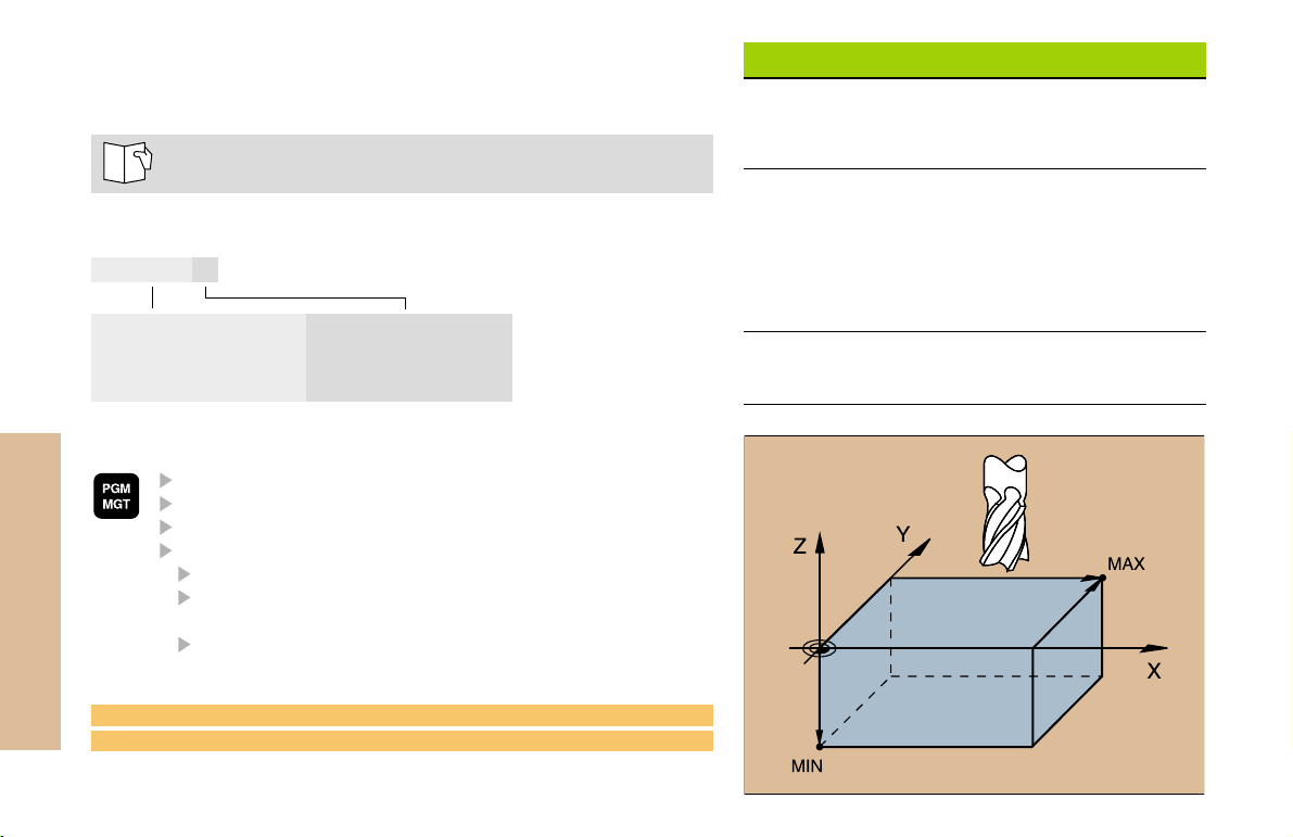
Define the blank form (BLK) for graphics:
Enter the spindle axis
Enter coordinates of the MIN point:
the smallest X, Y and Z coordinates
Enter coordinates of the MAX point:
the greatest X, Y and Z coordinates
1 BLK FORM 0.1 Z X+0 Y+0 Z-50
2 BLK FORM 0.2 X+100 Y+100 Z+0
Programs
in HEIDENHAIN format
in ISO format
Tables for
Tools
Datums
Pallets
Cutting data
Positions
Texts as
ASCII files
.H
.I
.T
.D
.P
.CDT
.PNT
.A
4
Page 4
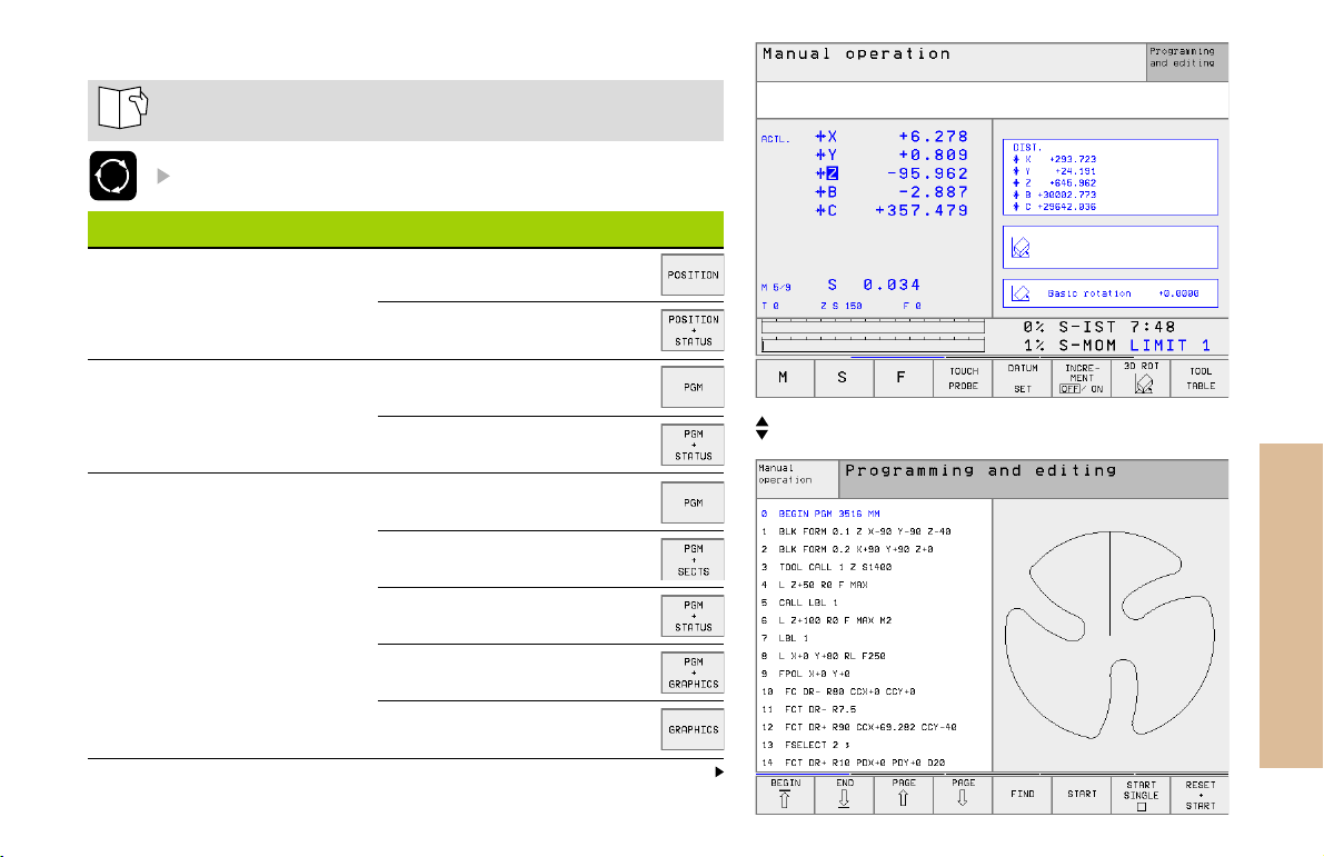
Choosing the Screen Layout
See Introduction, the TNC 426, TNC 430
Show soft keys for setting the screen layout
Mode of operation Screen contents
Manual operation
Electronic handwheel
Positioning with
manual data input
Program run,
full sequence
Program run,
single block test run
Positions
Positions at left
Status at right
Program
Program at left
Status at right
Program
Program at left
Program structure at right
Program at left
Status at right
Program at left
Graphics at right
Graphics
Positions at left, status at right
Program at left, graphics at right
Fundamentals
Continued
5
Page 5
Mode of operation Screen contents
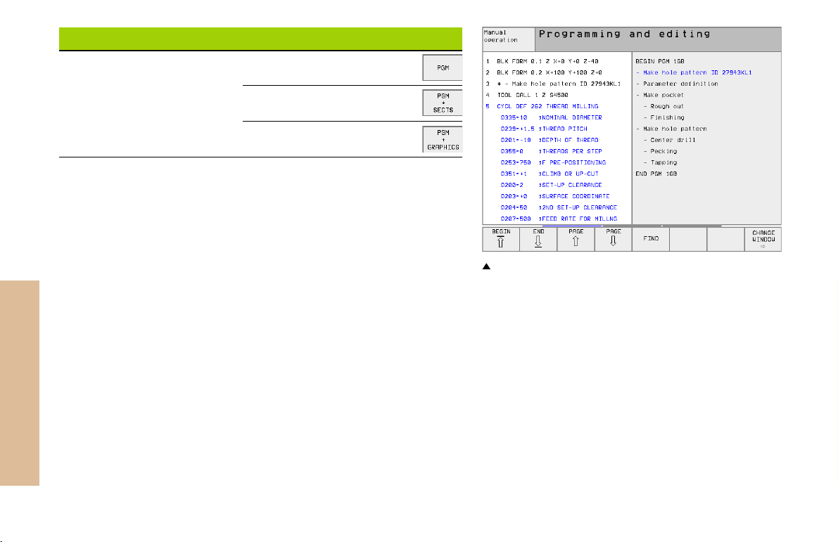
Programming and editing
Program
Program at left
Program structure at right
Program at left
Programming graphics at right
Fundamentals
6
Program at left, program structure at right
Page 6
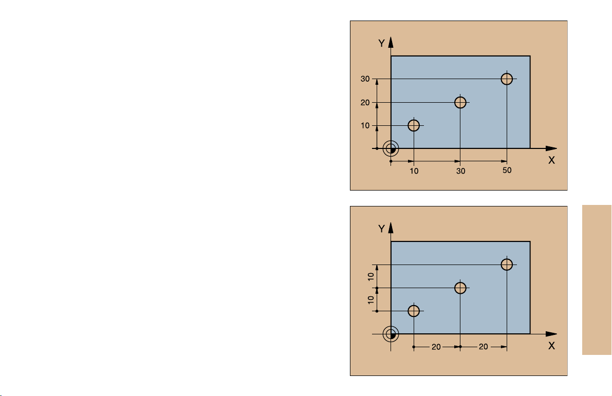
Absolute Cartesian Coordinates
The dimensions are measured from the current datum.
The tool moves to the absolute coordinates.
Programmable axes in an NC block
Linear motion: 5 axes
Circular motion: 2 linear axes in a plane or
3 linear axes with cycle 19 WORKING PLANE
Incremental Cartesian Coordinates
The dimensions are measured from the last programmed position of
the tool.
The tool moves by the incremental coordinates.
Fundamentals
7
Page 7
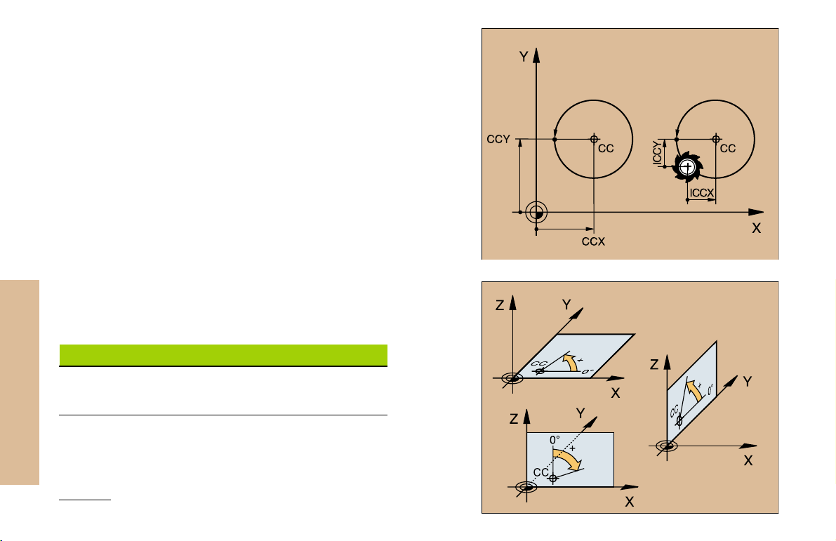
Circle Center and Pole: CC
The circle center (CC) must be entered to program circular tool
movements with the path function C (see page 21). CC is also needed
to define the pole for polar coordinates.
CC is entered in Cartesian coordinates*.
An absolutely defined circle center or pole is always measured from
the workpiece datum.
An incrementally defined circle center or pole is always measured
from the last programmed position of the workpiece.
Fundamentals
Angle Reference Axis
Angles such as a polar coordinate angle PA or an angle of rotation
ROT are measured from the angle reference axis.
Working plane Ref. axis and 0° direction
X/Y X
Y/Z Y
Z/X Z
8
*Circle center in polar coordinates: See FK programming
Page 8
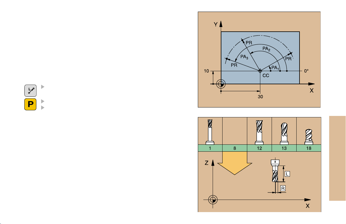
Polar Coordinates
Dimensions in polar coordinates are referenced to the pole (CC).
A position in the working plane is defined by
Polar coordinate radius PR = Distance of the position from the pole
Polar coordinate angle PA = Angle from the angle reference axis to
the straight line CC PR
Incremental dimensions
Incremental dimensions in polar coordinates are measured from the
last programmed position.
Programming polar coordinates
Select the path function
Press the P key
Answer the dialog prompts
Defining Tools
Tool data
Every tool is designated by a tool number between 1 and 254 or, if
you are using tool tables, by a tool name.
Entering tool data
You can enter the tool data (length L and radius R)
in a tool table (centrally, Program TOOL.T)
or
within the part program in TOOL DEF blocks (locally)
Fundamentals
9
Page 9
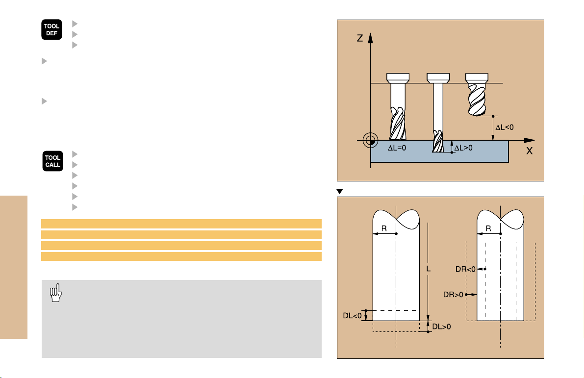
Program the tool length as its difference DL to the zero tool:
DL>0: The tool is longer than the zero tool
DL<0: The tool is shorter than the zero tool
With a tool presetter you can measure the actual tool length, then
program that length.
Calling the tool data
Fundamentals
3 TOOL DEF 6 L+7.5 R+3
4 TOOL CALL 6 Z S2000 F650 DL+1 DR+0.5
5 L Z+100 R0 FMAX
6 L X-10 Y-10 R0 FMAX M6
Tool change
10
Tool number
Tool length L
Tool radius R
Tool number or name
Working spindle axis: tool axis
Spindle speed S
Feed rate
Tool length oversize DL (e.g. to compensate wear)
Tool radius oversize DR (e.g. to compensate wear)
Beware of tool collision when moving to the tool change
position!
The direction of spindle rotation is defined by M function:
M3: Clockwise
M4: Counterclockwise
The maximum permissible oversize for tool radius or length
is ±99.999mm!
Oversizes on an end mill
Page 10
Tool Compensation
The TNC compensates the length L and radius R of the tool during
machining.
Length compensation
Beginning of effect:
Tool movement in the spindle axis
End of effect:
Tool exchange or tool with the length L=0
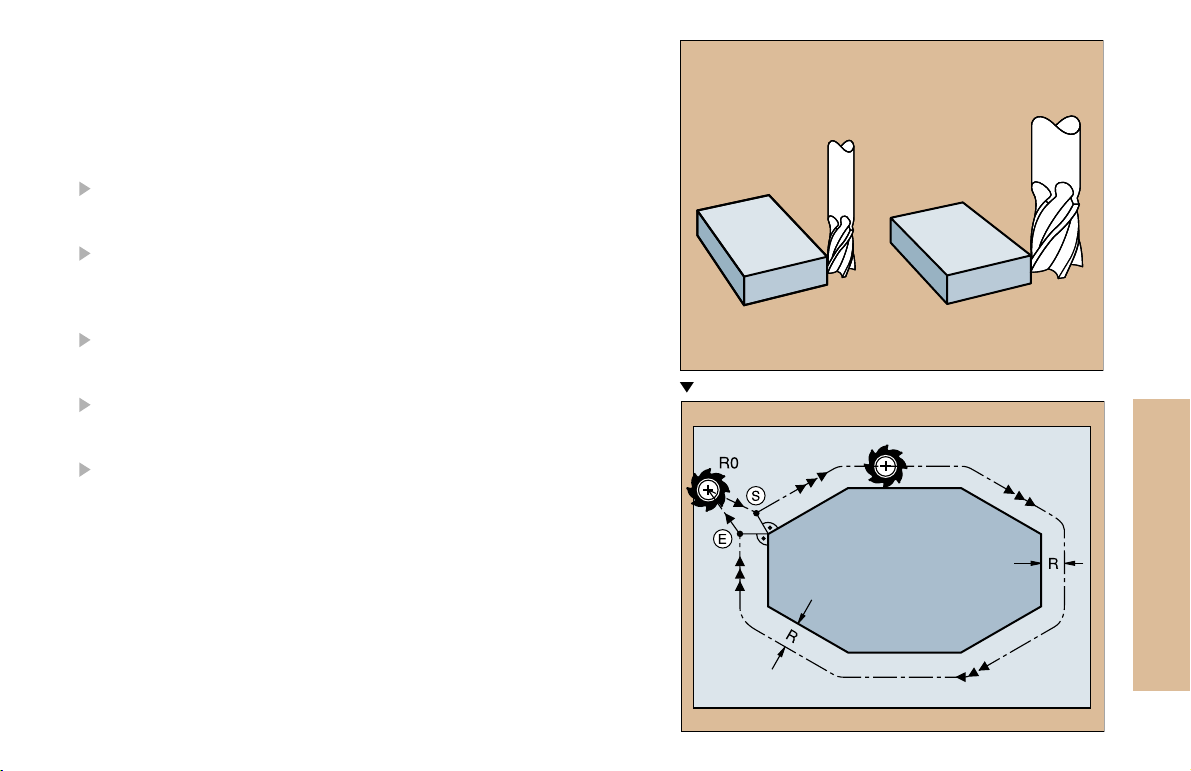
Radius compensation
Beginning of effect:
Tool movement in the working plane with RR or RL
End of effect:
Execution of a positioning block with R0
Working without radius compensation (e.g. drilling):
Tool movement with R0
S = Start; E = End
Fundamentals
11
Page 11
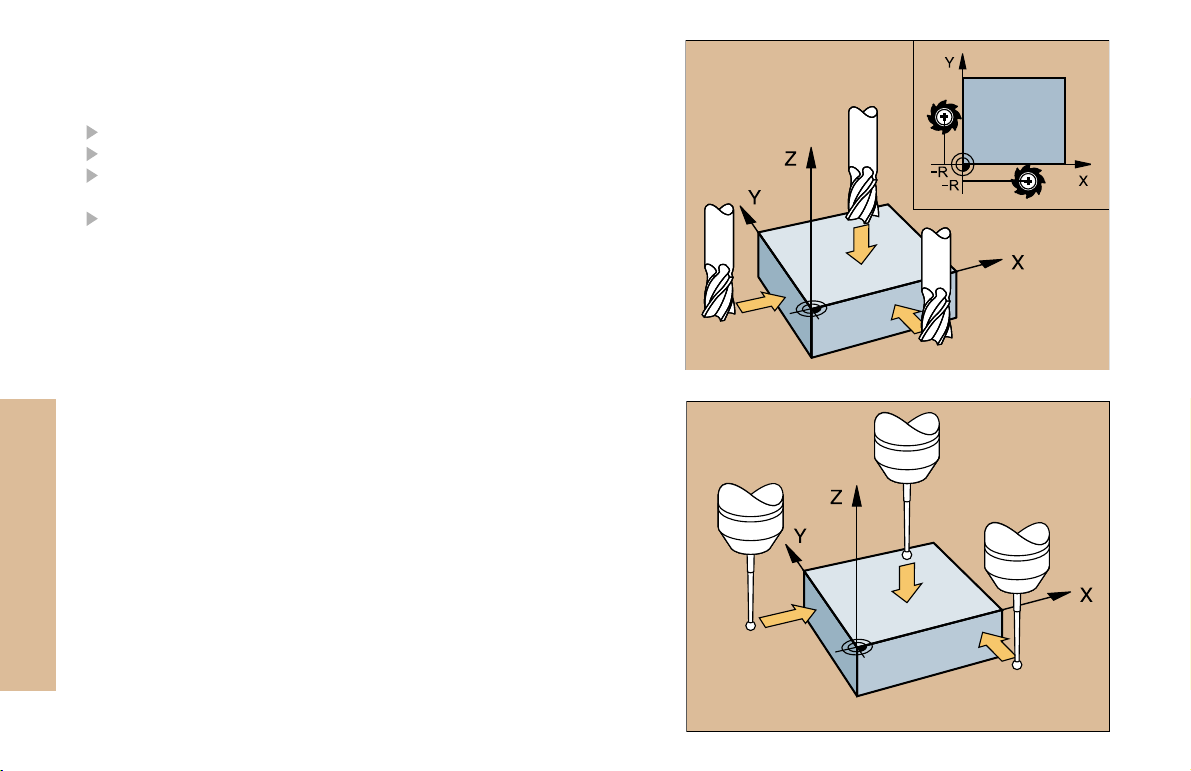
Datum Setting without a 3-D Touch Probe
During datum setting you set the TNC display to the coordinates of a
known position on the workpiece:
Insert a zero tool with known radius
Select the manual operation or electronic handwheel mode
Touch the reference surface in the tool axis with the tool and enter
its length
Touch the reference surface in the working plane with the tool and
enter the position of the tool center
Fundamentals
Setup and Measurement with 3-D Touch Probes
A HEIDENHAIN 3-D touch probe enables you to setup the machine very
quickly, simply and precisely.
Besides the probing functions for workpiece setup on the Manual and
Electronic Handwheel modes, the Program Run modes provide a
series of measuring cycles (see also the User's Manual for Touch
Probe Cycles):
Measuring cycles for measuring and compensating workpiece
misalignment
Measuring cycles for automatic datum setting
Measuring cycles for automatic workpiece measurement with
tolerance checking and automatic tool compensation
12
Page 12
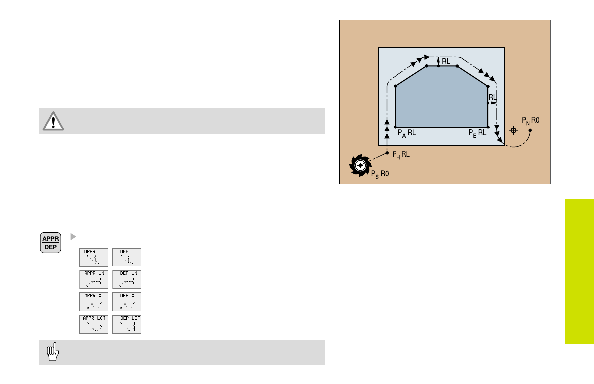
Contour Approach and Departure
Starting point P
PS lies outside of the contour and must be approached without radius
S
compensation.
Auxiliary point P
PH lies outside of the contour and is calculated by the TNC.
The tool moves from the starting point P
P
at the feed rate last programmed feed rate!
H
First contour point P
The first contour point PA is programmed in the APPR (approach) block.
H
and last contour point P
A
to the auxiliary point
S
E
The last contour point is programmed as usual.
End point P
PN lies outside of the contour and results from the DEP (departure)
block. P
N
is automatically approached with R0.
N
Path Functions for Approach and Departure
Press the soft key with the desired path function:
Straight line with tangential connection
Straight line perpendicular to the
contour point
Circular arc with tangential connection
Straight line segment tangentially connected to the contour through an arc
Contour Approach
and Departure
Program a radius compensation in the APPR block!
DEP blocks set the radius compensation to 0!
13
Page 13
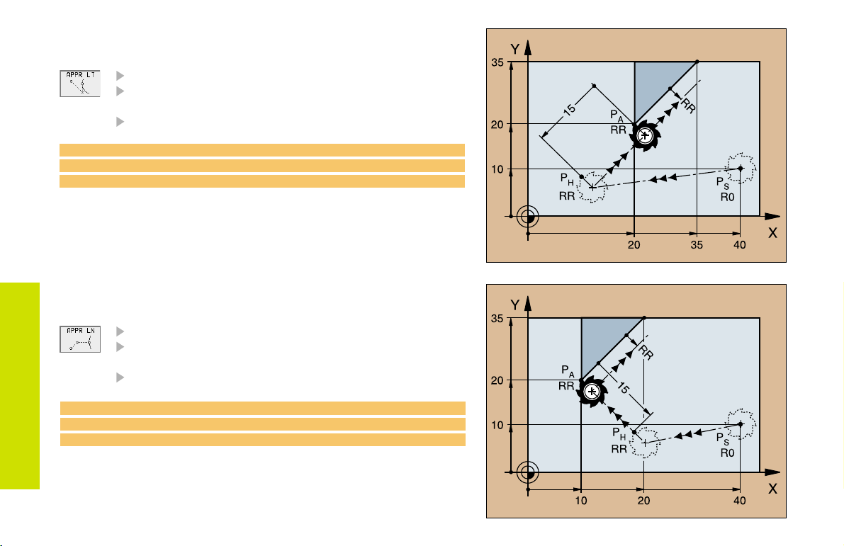
Approaching on a Straight Line with
Tangential Connection
Coordinates for the first contour point P
Distance Len (length) from PH to P
Enter a length Len > 0
Tool radius compensation RR/RL
A
7 L X+40 Y+10 R0 FMAX M3
8 APPR LT X+20 Y+20 LEN 15 RR F100
9 L X+35 Y+35
Contour Approach
and Departure
Approaching on a Straight Line Perpendicular
to the First Contour Element
Coordinates for the first contour point P
Distance Len (length) from PH to P
Enter a length Len > 0
Tool radius compensation RR/RL
7 L X+40 Y+10 R0 FMAX M3
8 APPR LN X+10 Y+20 LEN 15 RR F100
9 L X+20 Y+35
A
A
A
14
Page 14
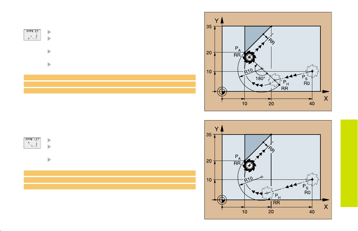
Approaching Tangentially on an Arc
Coordinates for the first contour point P
Radius R
Enter a radius R > 0
Circle center angle (CCA)
Enter a CCA > 0
Tool radius compensation RR/RL
A
7 L X+40 Y+10 R0 FMAX M3
8 APPR CT X+10 Y+20 CCA 180 R10 RR F100
9 L X+20 Y+35
Approaching Tangentially on an Arc
and a Straight Line
Coordinates for the first contour point P
Radius R
Enter a radius R > 0
Tool radius compensation RR/RL
7 L X+40 Y+10 R0 FMAX M3
8 APPR LCT X+10 Y+20 R10 RR F100
9 L X+20 Y+35
A
Contour Approach
and Departure
15
Page 15
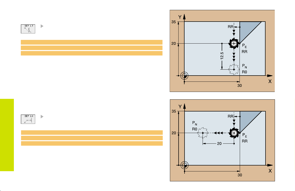
Departing Tangentially on a Straight Line
Distance Len (length) from PE to P
Enter a length Len > 0
N
23 L X+30 Y+35 RR F100
24 L Y+20 RR F100
25 DEP LT LEN 12.5 F100 M2
Contour Approach
and Departure
Departing on a Straight Line
Perpendicular to the Last Contour Element
Distance Len (length) from PE to P
Enter a length Len > 0
23 L X+30 Y+35 RR F100
24 L Y+20 RR F100
25 DEP LN LEN+20 F100 M2
N
16
Page 16
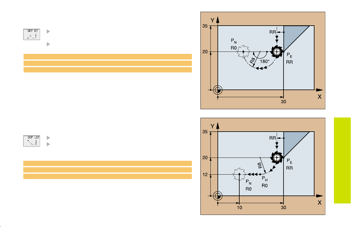
Departing Tangentially on an Arc
Radius R
Enter a radius R > 0
Circle center angle (CCA)
23 L X+30 Y+35 RR F100
24 L Y+20 RR F10
25 DEP CT CCA 180 R+8 F100 M2
Departing on an Arc Tangentially Connecting
the Contour and a Straight Line
Coordinates of the end point P
Radius R
Enter a radius R > 0
23 L X+30 Y+35 RR F100
24 L Y+20 RR F100
25 DEP LCT X+10 Y+12 R8 F100 M2
N
Contour Approach
and Departure
17
Page 17
Path Functions for Positioning Blocks
Path functions
See Programming: Programming contours.
Programming the Direction of Traverse
Regardless of whether the tool or the workpiece is actually moving,
you always program as if the tool is moving and the workpiece is
stationary.
Entering the Target Positions
Target positions can be entered in Cartesian or polar coordinates
either as absolute or incremental values, or with both absolute and
incremental values in the same block.
Entries in the Positioning Block
Path Functions
A complete positioning block contains the following data:
Path function
Coordinates of the contour element end points (target position)
Radius compensation RR/RL/R0
Feed rate F
Miscellaneous function M
Before you execute a part program, always pre-position the tool to
prevent the possibility of damaging the tool or workpiece!
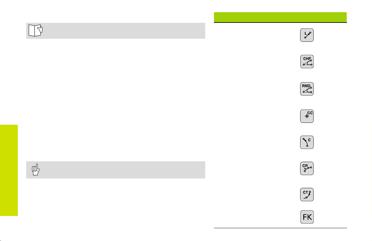
Straight line
Chamfer between two
straight lines
Corner rounding
Circle center or pole for
polar coordinates
Circular path aroundthe
circle center CC
Circular path with
known radius
Circular path with
tangential connection to
previous contour
Page 19
Page 20
Page 20
Page 21
Page 21
Page 22
Page 23
18
FK Free Contour
Programming
Page 25
Page 18

Straight Line
Coordinates of the straight line end point
Tool radius compensation RR/RL/R0
Feed rate F
Miscellaneous function M
With Cartesian coordinates:
7 L X+10 Y+40 RL F200 M3
8 L IX+20 IY-15
9 L X+60 IY-10
With polar coordinates:
12 CC X+45 Y+25
13 LP PR+30 PA+0 RR F300 M3
14 LP PA+60
15 LP IPA+60
16 LP PA+180
You must first define the pole CC before you can program
polar coordinates!
Program the pole CC only in Cartesian coordinates!
The pole CC remains effective until you define a new one!
Path Functions
19
Page 19
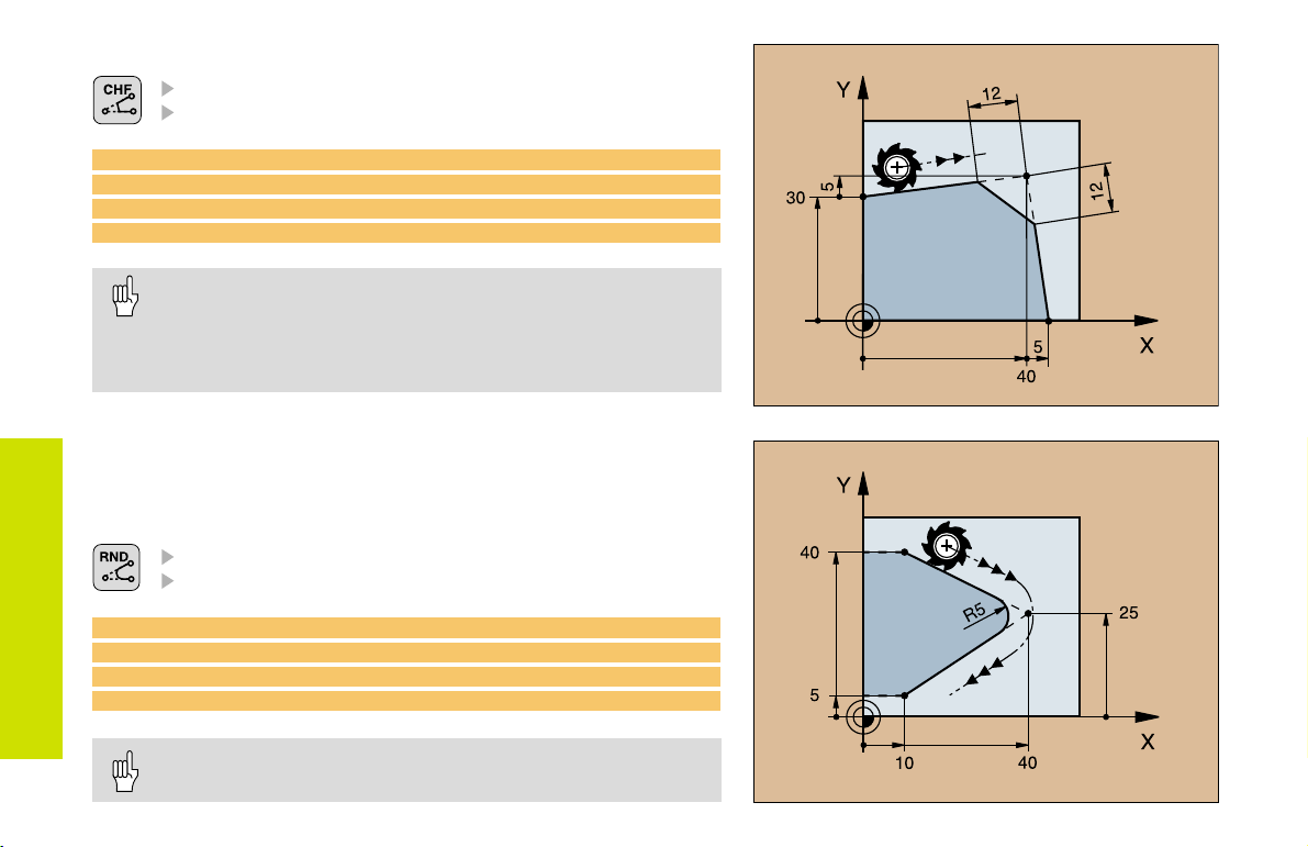
Inserting a Chamfer Between Two Straight Lines
Chamfer side length
Feed rate F for the chamfer
7 L X+0 Y+30 RL F300 M3
8 L X+40 IY+5
9 CHF 12 F250
10 L IX+5 Y+0
You cannot start a contour with a CHF block!
The radius compensation before and after the CHF block must
be the same!
An inside chamfer must be large enough to accommodate
the current tool!
Path Functions
Corner Rounding
The beginning and end of the arc extend tangentially from the previous
and subsequent contour elements.
Radius R of the circular arc
Feed rate F for corner rounding
5 L X+10 Y+40 RL F300 M3
6 L X+40 Y+25
7 RND R5 F100
8 L X+10 Y+5
20
An inside arc must be large enough to accommodate the
current tool!
Page 20
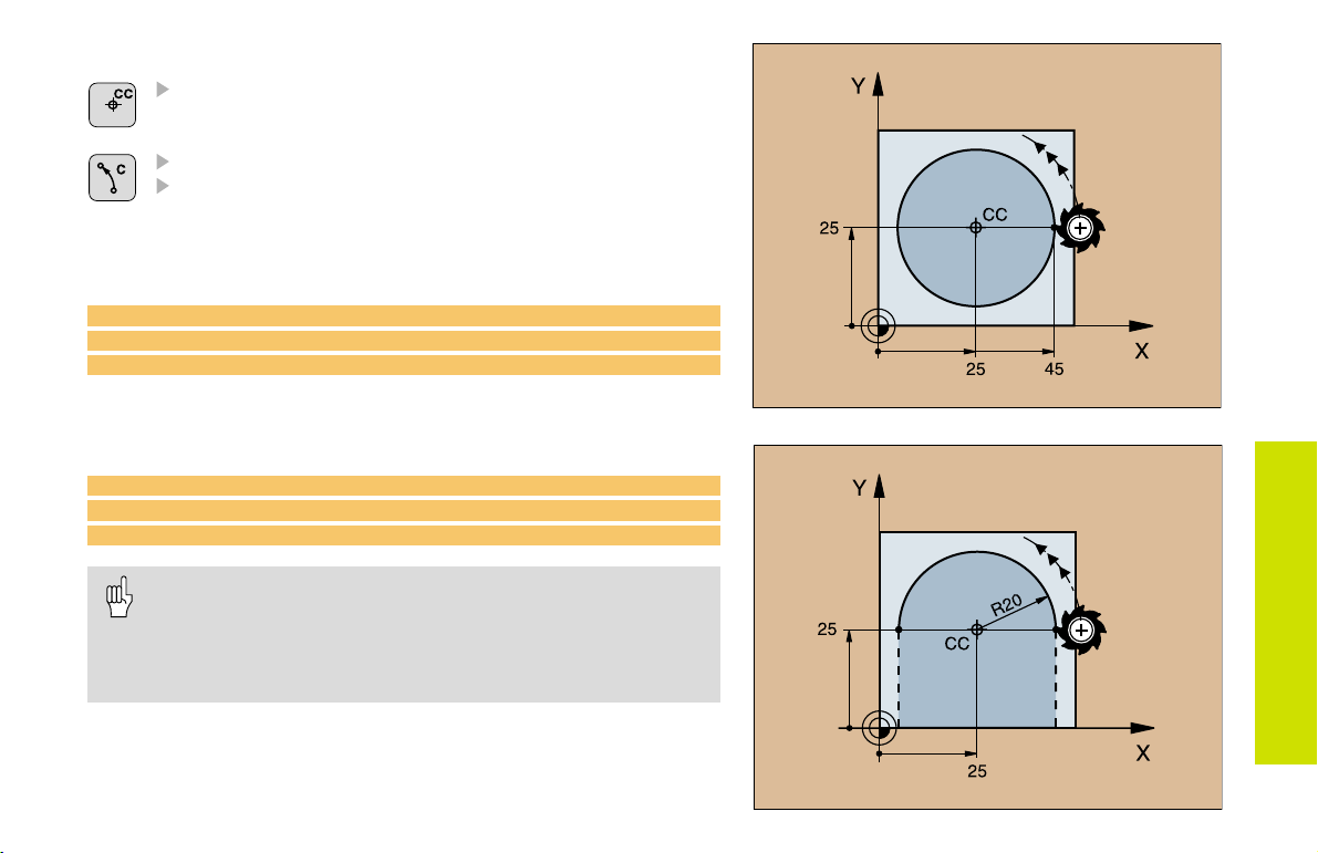
Circular Path Around the Circle Center CC
Coordinates of the circle center CC
Coordinates of the arc end point
Direction of rotation DR
C and CP enable you to program a complete circle in one block.
With cartesian coordinates:
5 CC X+25 Y+25
6 L X+45 Y+25 RR F200 M3
7 C X+45 Y+25 DR+
With polar coordinates:
18 CC X+25 Y+25
19 LP PR+20 PA+0 RR F250 M3
20 CP PA+180 DR+
Define the pole CC before programming polar coordinates!
Program the pole CC only in Cartesian coordinates!
The pole CC remains effective until you define a new one!
The arc end point can be defined only with the polar
coordinate angle (PA)!
Path Functions
21
Page 21
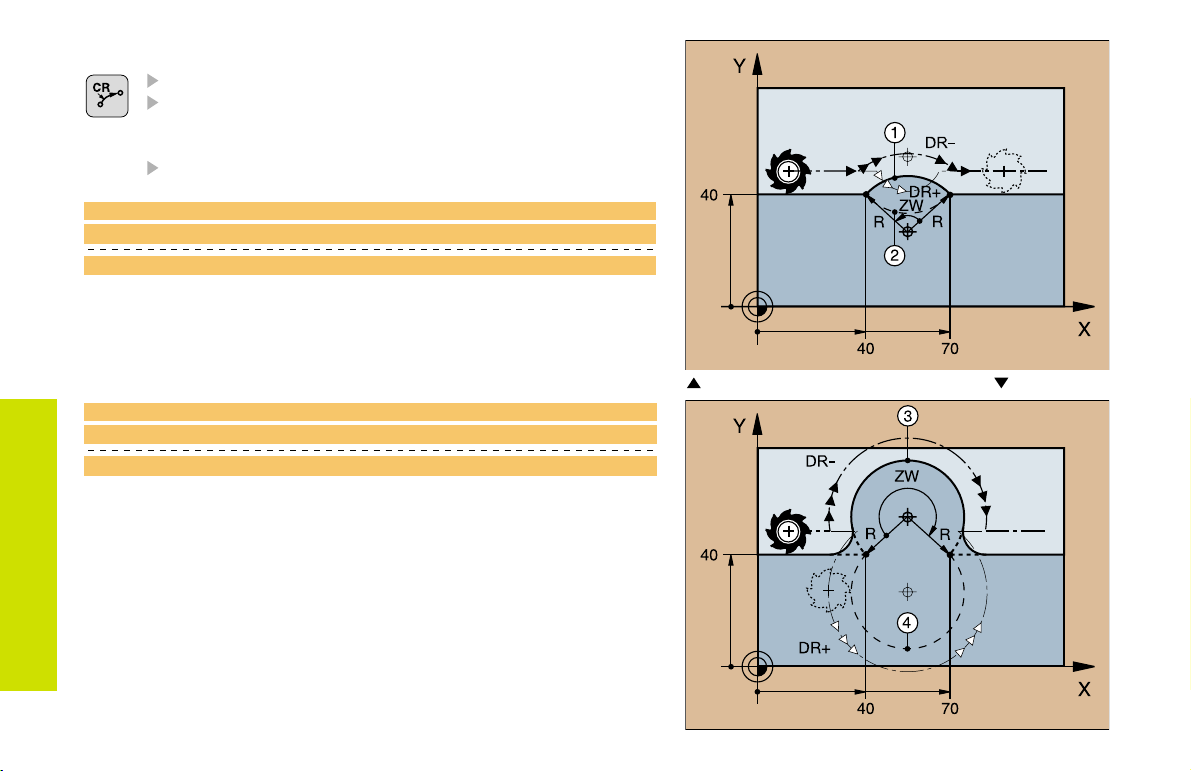
Circular Path with Known Radius (CR)
Coordinates of the arc end point
Radius R
If the central angle ZW > 180, R is negative.
If the central angle ZW < 180, R is positive.
Direction of rotation DR
10 L X+40 Y+40 RL F200 M3 Arc starting point
11 CR X+70 Y+40 R+20 DR- Arc
11 CR X+70 Y+40 R+20 DR+ Arc
1
2
or
Path Functions
10 L X+40 Y+40 RL F200 M3 Arc starting point
11 CR X+70 Y+40 R-20 DR- Arc
11 CR X+70 Y+40 R-20 DR+ Arc
22
3
4
or
Arcs
and
1
2
Arcs 3 and
4
Page 22
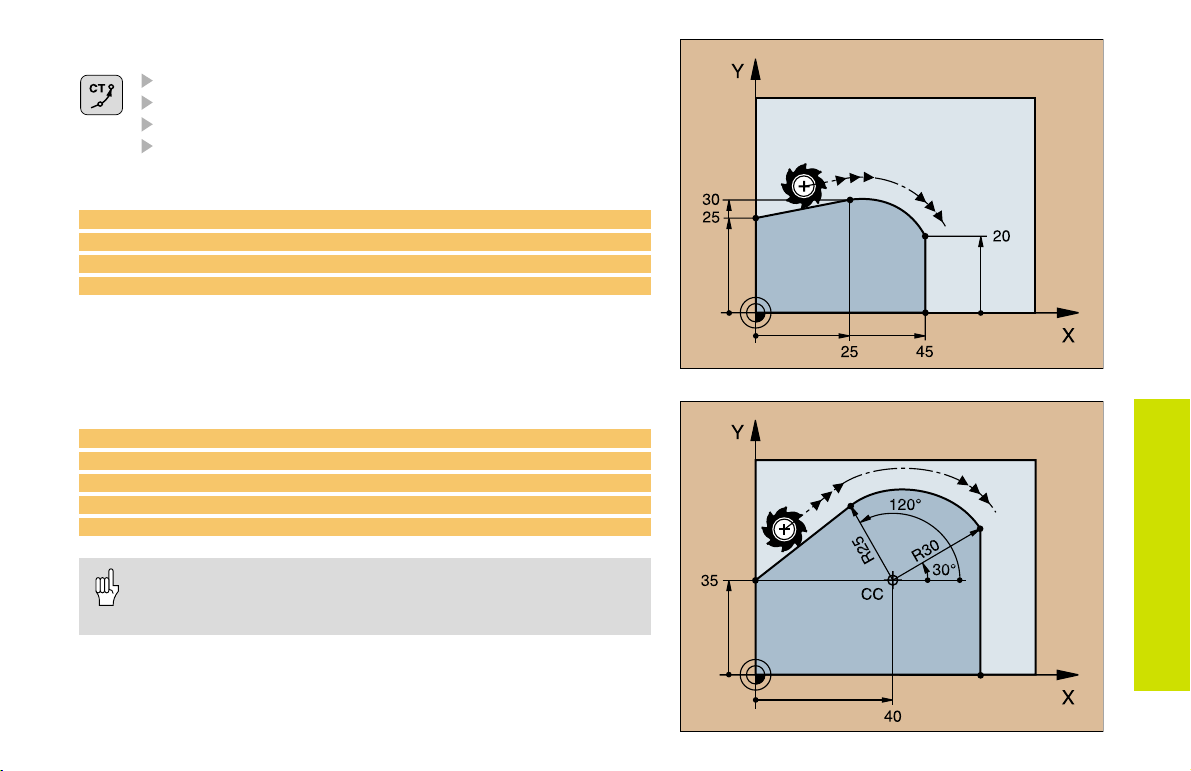
Circular Path CT with Tangential Connection
Coordinates of the arc end point
Radius compensation RR/RL/R0
Feed rate F
Miscellaneous function M
With cartesian coordinates:
5 L X+0 Y+25 RL F250 M3
6 L X+25 Y+30
7 CT X+45 Y+20
8 L Y+0
With polar coordinates:
12 CC X+40 Y+35
13 L X+0 Y+35 RL F250 M3
14 LP PR+25 PA+120
15 CTP PR+30 PA+30
16 L Y+0
Define the pole CC before programming polar coordinates!
Program the pole CC only in Cartesian coordinates!
The pole CC remains effective until you define a new one!
Path Functions
23
Page 23
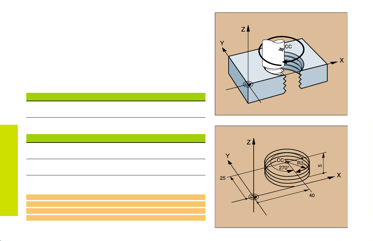
Helix (Only in Polar Coordinates)
Calculations (upward milling direction)
Path revolutions: n = Thread revolutions + overrun at start and
end of thread
Total height: h = Pitch P x path revolutions n
Incr. coord. angle: IPA = Path revolutions n x 360°
Start angle: PA = Angle at start of thread + angle for
overrun
Start coordinate: Z = Pitch P x (thread revolutions + thread
overrun at start of thread)
Shape of helix
Internal thread Work direction Direction Radius comp.
Right-hand Z+ DR+ RL
Left-hand Z+ DR RR
Path Functions
Right-hand Z DR RR
Left-hand Z DR+ RL
External thread
Right-hand Z+ DR+ RR
Left-hand Z+ DR RL
Right-hand Z DR RL
Left-hand Z DR+ RR
24
M6 x 1 mm thread with 5 revolutions
12 CC X+40 Y+25
13 L Z+0 F100 M3
14 LP PR+3 PA+270 RL
15 CP IPA-1800 IZ+5 DR- RL F50
:
Page 24
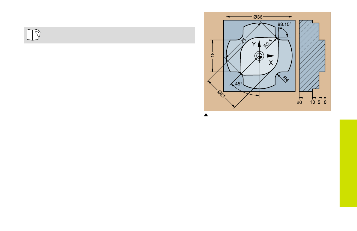
FK Free Contour Programming
See Programming Tool Movements FK Free Contour
Programming
If the end point coordinates are not given in the workpiece drawing
or if the drawing gives dimensions that cannot be entered with the
gray path function keys, you can still program the part by using the
FK Free Contour Programming.
Possible data on a contour element:
Known coordinates of the end point
Auxiliary points on the contour element
Auxiliary points near the contour element
A reference to another contour element
Directional data (angle) / position data
Data regarding the course of the contour
To use FK programming properly:
All contour elements must lie in the working plane.
Enter all available data on each contour element.
If a program contains both FK and conventional blocks, the FK
contour must be fully defined before you can return to conventional
programming.
These dimensions can be programmed with FK
FK Free Contour
Programming
25
Page 25
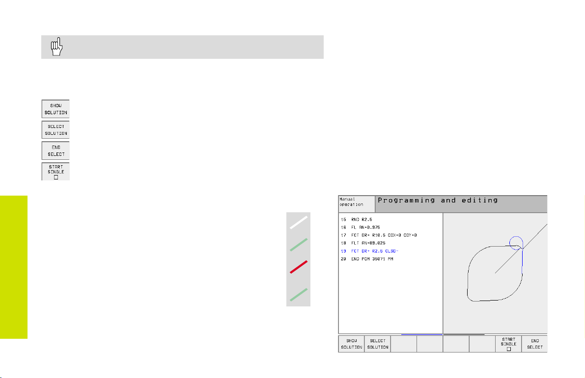
Working with the Interactive Graphics
Select the PGM+GRAPHICS screen layout!
The interactive graphics show the contour as you are programming it.
If the data you enter can apply to more than one solution, the following
soft keys will appear:
To show the possible solutions
To enter the displayed solution in the part program
To enter data for subsequent contour elements
FK Free Contour
Programming
Standard colors of the interactive graphics
Fully defined contour element
The displayed element is one of a limited number of
possible solutions
The element is one of an infinite number of solutions
Contour element from a subprogram
To graphically display the next programmed block
26
Page 26
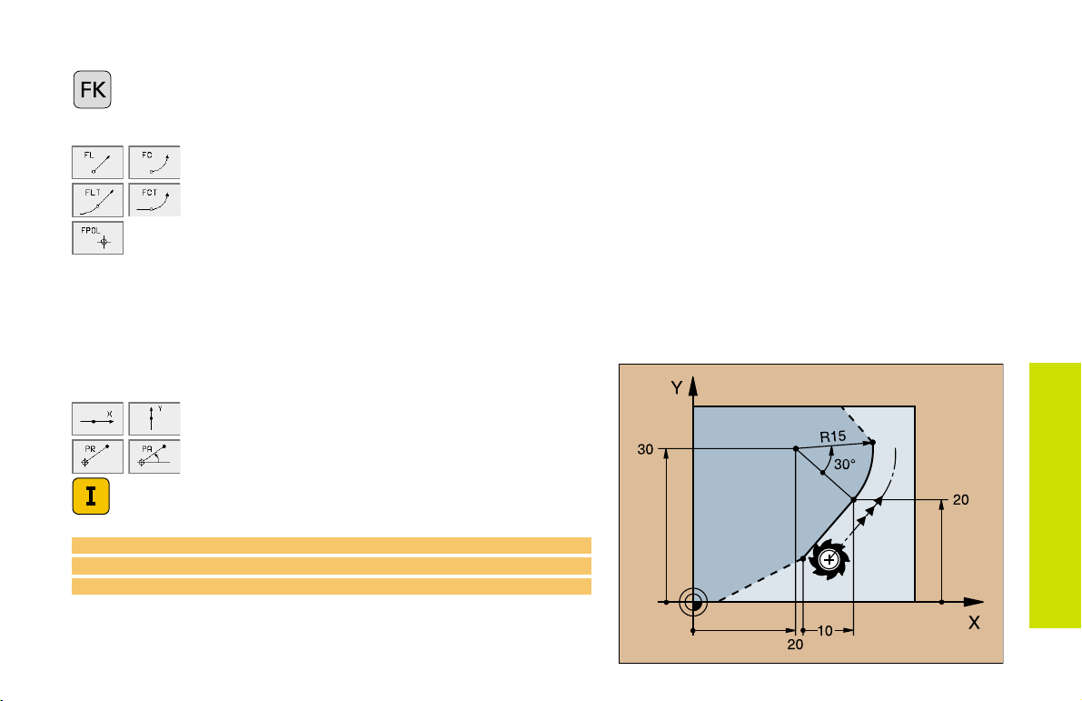
Initiating the FK Dialog
Initiate the FK dialog
Straight Circular
Contour element without tangential connection
Contour element with tangential connection
Pole for FK programming
End Point Coordinates X, Y or PA, PR
Cartesian coordinates X and Y
Polar coordinates referenced to FPOL
Incremental input
7 FPOL X+20 Y+30
8 FL IX+10 Y+20 RR F100
9 FCT PR+15 IPA+30 DR+ R15
FK Free Contour
Programming
27
Page 27
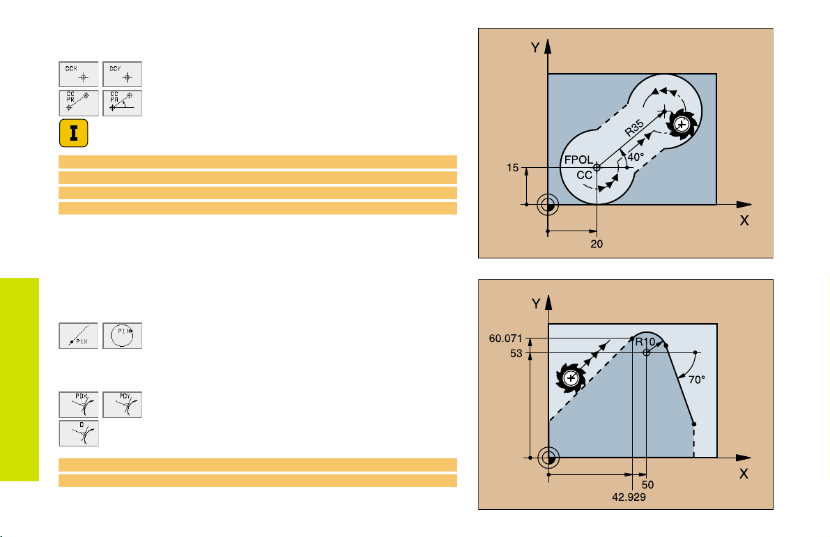
Circle Center (CC) in an FC/ FCT block
Cartesian coordinates of the circle center
Polar coordinates of the circle center
referenced to FPOL
Incremental input
10 FC CCX+20 CCY+15 DR+ R15
11 FPOL X+20 Y+15
...
13 FC DR+ R15 CCPR+35 CCPA+40
FK Free Contour
Programming
Auxiliary Points
... P1, P2, P3 on a contour
:
For straight lines
For circles: up to 3 auxiliary points
... next to a contour
Coordinates of the auxiliary points
Perpendicular distance
up to 2 auxiliary points
28
13 FC DR- R10 P1X+42.929 P1Y+60.071
14 FLT AN-70 PDX+50 PDY+53 D10
Page 28
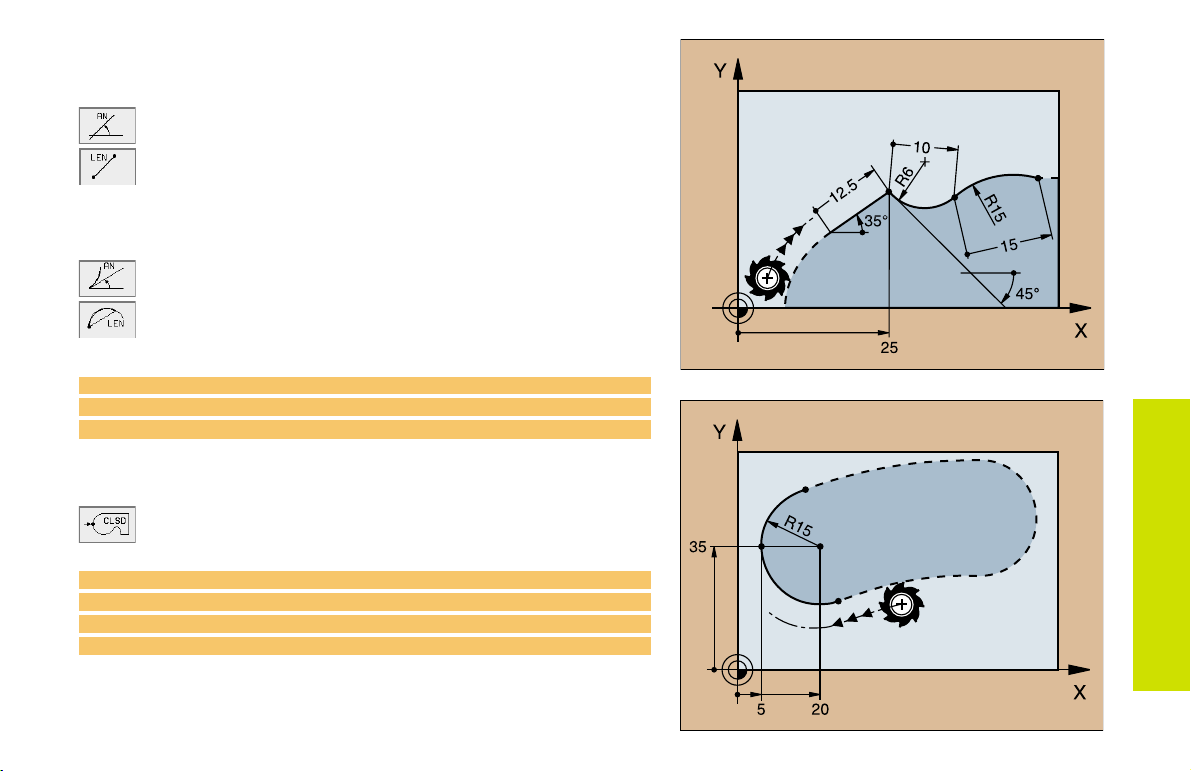
Direction and Length of the Contour Element
Data on a straight line
Gradient angle of a straight line
Length of a straight line
Data on a circular path
Gradient angle of the entry tangent
Length of an arc chord
27 FLT X+25 LEN 12.5 AN+35 RL F200
28 FC DR+ R6 LEN 10 AN-45
29 FCT DR- R15 LEN 15
Identifying a closed contour
Beginning: CLSD+
End: CLSD
12 L X+5 Y+35 RL F500 M3
13 FC DR- R15 CLSD+ CCX+20 CCY+35
...
17 FCT DR- R+15 CLSD-
FK Free Contour
Programming
29
Page 29
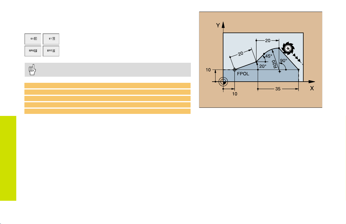
Values Relative to Block N:
Entering Coordinates
Cartesian coordinates relative to block N
Polar coordinates relative to block N
Relative data must be entered incrementally!
CC can also be programmed in relative values!
12 FPOL X+10 Y+10
13 FL PR+20 PA+20
14 FL AN+45
FK Free Contour
15 FCT IX+20 DR- R20 CCA+90 RX 13
Programming
16 FL IPR+35 PA+0 RPR 13
30
Page 30
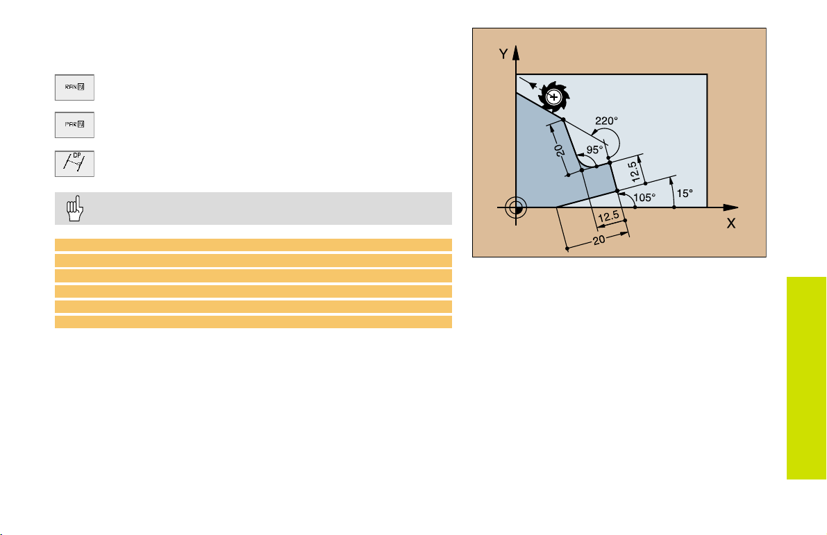
Values Relative to Block N:
Direction and Distance of the Contour Element
Gradient angle
Parallel to a straight contour element
Parallel to the entry tangent of an arc
Distance from a parallel element
Always enter relative values incrementally!
17 FL LEN 20 AN+15
18 FL AN+105
19 FL LEN 12.5 PAR 17 DP 12.5
20 FSELECT 2
21 FL LEN 20 IAN+95
22 FL IAN+220 RAN 18
FK Free Contour
Programming
31
Page 31

Values Relative to Block N:
Circle Center CC
Cartesian coordinates of a circle center relative to
block N
Polar coordinates of the circle center relative to
block N
Always enter relative data as incremental values!
FK Free Contour
Programming
13 FL ...
14 FL X+18 Y+35
15 FL ...
16 FL ...
17 FC DR- R10 CCA+0 ICCX+20 ICCY-15
RCCX12 RCCY14
32
12 FL X+10 Y+10 RL
Page 32

Subprograms and Program Section
Repeats
Subprograms and program section repeats enable you to program a
machining sequence once and then run it as often as needed.
Working with Subprograms
The main program runs up to the subprogram call CALL LBL1.
1
The subprogram labeled with LBL1 runs through to its end LBL0.
2
The main program resumes.
3
It's good practice to place subprograms after the main program
end (M2).
Answer the dialog prompt REP with the NOENT key!
You cannot call LBL0!
Working with Program Section Repeats
The main program runs up to the call for a section repeat CALL LBL1
1
REP2/2.
The program section between LBL1 and CALL LBL1 REP2/2 is
2
repeated the number of times indicated with REP.
After the last repetition the main program resumes.
3
S = Jump; R = Return jump
Subprograms
Altogether, the program section is run once more than the
number of programmed repeats!
33
Page 33

Subprogram Nesting:
A Subprogram within a Subprogram
The main program runs up to the first subprogram call CALL LBL1.
1
Subprogram 1 runs up to the second subprogram call CALL LBL2.
2
Subprogram 2 runs to its end.
3
Subprogram 1 resumes and runs to its end.
4
The main program resumes.
5
A subprogram cannot call itself!
Subprograms can be nested up to a maximum depth
of 8 levels!
Subprograms
34
= Jump; R = Return jump
S
Page 34

Any Program as a Subprogram
The calling program A runs up to the program call CALL PGM B.
1
The called program B runs through to its end.
2
The calling program A resumes.
3
The called program must not end with M2 or M30!
S = Jump; R = Return jump
Subprograms
35
Page 35

Working with Cycles
Certain frequently needed machining sequences are stored in the TNC
as cycles. Coordinate transformations and some special functions are
also available as cycles.
In a cycle, positioning data entered in the tool axis are
always incremental, even without the I key!
The algebraic sign of the cycle parameter depth determines
the working direction!
Example
6 CYCL DEF 1.0 PECKING
7 CYCL DEF 1.1 SET UP 2
8 CYCL DEF 1.2 DEPTH -15
Working with Cycles
9 CYCL DEF 1.3 PECKG 10
...
Feed rates are entered in mm/min, the dwell time in seconds.
Defining cycles
Select the Cycle Overview:
Select the cycle group
Cycles for Machining Holes
and Threads
1 PECKING Page 39
200 DRILLING Page 40
201 REAMING Page 41
202 BORING Page 42
203 UNIVERSAL DRILLING Page 43
204 COUNTERBORE BACK Page 44
205 UNIVERSAL PECKING Page 45
208 BORE MILLING Page 46
2 TAPPING Page 47
206 TAPPING NEW Page 48
17 RIGID TAPPING Page 48
207 RIGID TAPPING NEW Page 49
18 THREAD CUTTING Page 49
209 TAPPING W/ CHIP BRKG Page 50
262 THREAD MILLING Page 51
263 THREAD MLLNG/CNTSNKG Page 52
264 THREAD DRILLNG/MLLNG Page 53
265 HEL. THREAD DRLG/MLG Page 54
267 OUTSIDE THREAD MLLNG Page 55
36
Select the cycle
Continued on next page
Page 36

Pockets, Studs, and Slots
4 POCKET MILLING Page 56
212 POCKET FINISHING Page 57
213 STUD FINISHING Page 58
5 CIRCULAR POCKET MILLING Page 59
214 CIRCULAR POCKET FINISHING Page 60
215 CIRCULAR STUD FINISHING Page 61
3 SLOT MILLING Page 62
210 SLOT WITH RECIP. PLUNGE Page 63
211 CIRCULAR SLOT Page 64
SL Cycles
14 CONTOUR GEOMETRY Page 67
20 CONTOUR DATA Page 68
21 PILOT DRILLING Page 69
22 ROUGH-OUT Page 69
23 FLOOR FINISHING Page 70
24 SIDE FINISHING Page 70
25 CONTOUR TRAIN Page 71
27 CYLINDER SURFACE Page 72
28 CYLINDER SURFACE SLOT Page 73
Point Patterns
220 CIRCULAR PATTERN Page 65
221 LINEAR PATTERN Page 66
Multipass Milling
30 RUN DIGITIZED DATA Page 74
230 MULTIPASS MILLING Page 75
231 RULED SURFACE Page 76
Working with Cycles
Cycles for Coordinate Transformations
7 DATUM SHIFT Page 78
247 DATUM SETTING Page 79
8 MIRROR IMAGE Page 80
10 ROTATION Page 81
19 WORKING PLANE Page 82
11 SCALING FACTOR Page 83
26 AXIS-SPECIFIC SCALING Page 84
Spezial Cycles
9 DWELL TIME Page 85
12 PGM CALL Page 85
13 ORIENTED SPINDLE STOP Page 86
32 TOLERANCE Page 87
37
Page 37

Graphic Support During Cycle Programming
As you create a program, the TNC provides you with graphic illustrations of the input parameters.
Calling a Cycle
The following cycles are effective as soon as they are defined:
Cycles for coordinate transformations
DWELL TIME cycle
The SL cycles CONTOUR GEOMETRY and CONTOUR DATA
Point patterns
TOLERANCE cycle
All other cycles go into effect when they are called through
CYCL CALL: effective for one block
CYCL CALL PAT: used non-modally in connection with point tables
Working with Cycles
M99: effective for one block
M89: effective until canceled (depends on machine parameter
settings)
38
Page 38

Cycles for Machining
Holes and Threads
PECKING (1)
CYCL DEF: Select Cycle 1 PECKING
Set-up clearance:
Total hole depth (distance from the workpiece surface to the bottom
of the hole):
Pecking depth:
Dwell time in seconds
Feed rate F
If the total hole depth is greater than or equal to the pecking depth,
the tool drills the entire hole in one plunge.
6 CYCL DEF 1.0 PECKING
7 CYCL DEF 1.1 SET UP +2
8 CYCL DEF 1.2 DEPTH -15
9 CYCL DEF 1.3 PECKG +7.5
10 CYCL DEF 1.4 DWELL 1
11 CYCL DEF 1.5 F80
12 L Z+100 R0 FMAX M6
13 L X+30 Y+20 FMAX M3
14 L Z+2 FMAX M99
15 L X+80 Y+50 FMAX M99
16 L Z+100 FMAX M2
A
B
C
Cycles for Machining
Holes and Threads
39
Page 39

DRILLING (200)
CYCL DEF: Select Cycle 200 DRILLING
The TNC automatically pre-positions the tool in the tool axis. If the
depth is greater than or equal to the pecking depth, the tool drills to
Cycles for Machining
the depth in one plunge.
Holes and Threads
11 CYCL DEF 200 DRILLING
Q200 = 2 ;SET-UP CLEARANCE
Q201 = -15 ;DEPTH
Q206 = 250 ;FEED RATE FOR PLUNGING
Q202 = 5 ;PLUNGING DEPTH
Q210 = 0 ;DWELL TIME AT TOP
Q203 = +0 ;SURFACE COORDINATE
Q204 = 100 ;2ND SET-UP CLEARANCE
Q211 = 0.1 ;DWELL TIME AT DEPTH
12 L Z+100 R0 FMAX M6
13 L X+30 Y+20 FMAX M3
14 CYCL CALL
15 L X+80 Y+50 FMAX M99
16 L Z+100 FMAX M2
40
Set-up clearance: Q200
Depth Distance between workpiece surface and bottom
of hole: Q201
Feed rate for plunging: Q206
Pecking depth: Q202
Dwell time at top: Q210
Surface coordinate: Q203
2nd set-up clearance: Q204
Dwell time at depth: Q211
Page 40

REAMING (201)
CYCL DEF: Select Cycle 201 REAMING
Set-up clearance: Q200
Depth Distance between workpiece surface and bottom
of hole: Q201
Feed rate for plunging: Q206
Dwell time at depth: Q211
Retraction feed rate: Q208
Surface coordinate: Q203
2nd set-up clearance: Q204
The TNC automatically pre-positions the tool in the tool axis.
11 CYCL DEF 201 REAMING
Q200 = 2 ;SET-UP CLEARANCE
Q201 = -15 ;DEPTH
Q206 = 100 ;FEED RATE FOR PLNGNG
Q211 = 0.5 ;DWELL TIME AT DEPTH
Q208 = 250 ;RETRACTION FEED RATE
Q203 = +0 ;SURFACE COORDINATE
Q204 = 100 ;2ND SET-UP CLEARANCE
12 L Z+100 R0 FMAX M6
13 L X+30 Y+20 FMAX M3
14 CYCL CALL
15 L X+80 Y+50 FMAX M99
16 L Z+100 FMAX M2
Cycles for Machining
Holes and Threads
41
Page 41

BORING (202)
CYCL DEF: Select Cycle 202 BORING
Set-up clearance: Q200
Depth Distance between workpiece surface and bottom of hole:
Q201
Feed rate for plunging: Q206
Cycles for Machining
Holes and Threads
Dwell time at depth: Q211
Retraction feed rate: Q208
Surface coordinate: Q203
2nd set-up clearance: Q204
Disengaging directn (0/1/2/3/4) at bottom of hole: Q214
Angle for oriented spindle stop: Q336
The TNC automatically pre-positions the tool in the tool axis.
The machine and TNC must be prepared for the BORING
cycle by the machine tool builder!
This cycle requires a position-controlled spindle!
Danger of collision! Choose a disengaging direction that
moves the tool away from the wall of the hole.
42
Page 42

UNIVERSAL DRILLING (203)
CYCL DEF: Select Cycle 203 UNIVERSAL DRILLING
Set-up clearance: Q200
Depth Distance between workpiece surface and bottom
of hole: Q201
Feed rate for plunging: Q206
Pecking depth: Q202
Dwell time at top: Q210
Surface coordinate: Q203
2nd set-up clearance: Q204
Decrement after each pecking depth: Q212
Nr of breaks Number of chip breaks before retraction: Q213
Min. pecking depth if a decrement has been entered: Q205
Dwell time at depth: Q211
Retraction feed rate: Q208
Retract dist. for chip breaking: Q256
The TNC automatically pre-positions the tool in the tool axis. If the
depth is greater than or equal to the pecking depth, the tool drills to
the depth in one plunge.
Cycles for Machining
Holes and Threads
43
Page 43

COUNTERBORE BACK (204)
CYCL DEF: Select Cycle 204 COUNTERBORE BACK
Set-up clearance: Q200
Depth of counterbore: Q249
Material thickness: Q250
Tool edge off-center distance: Q251
Cycles for Machining
Holes and Threads
Tool edge height: Q252
Feed rate for pre-positioning: Q253
Feed rate for counterboring: Q254
Dwell time at counterbore floor: Q255
Workpiece surface coordinate: Q203
2nd set-up clearance: Q204
Disengaging direction (0/1/2/3/4): Q214
Angle for oriented spindle stop: Q336
The machine and TNC must be prepared for the
COUNTERBORE BACK cycle by the machine tool builder!
This cycle requires a position-controlled spindle!
Danger of collision! Select the disengaging direction that
gets the tool clear of the counterbore floor!
Use this cycle only with a reverse boring bar!
44
Page 44

UNIVERSAL PECKING (205)
CYCL DEF: Select Cycle 205 UNIVERSAL PECKING
Set-up clearance: Q200
Depth: Distance between workpiece surface
and bottom of hole: Q201
Feed rate for plunging: Q206
Pecking depth: Q202
Workpiece surface coordinate: Q203
2nd set-up clearance: Q204
Decrement after each pecking depth: Q212
Minimum pecking depth if decrement value entered: Q205
Upper advanced stop distance: Q258
Lower advanced stop distance: Q259
Infeed depth for chip breaking: Q257
Retract dist. for chip breaking: Q256
Dwell time at bottom: Q211
Cycles for Machining
Holes and Threads
45
Page 45

BORE MILLING (208)
Pre-position to the center of the hole with R0
CYCL DEF: Select Cycle 208 BORE MILLING
Set-up clearance: Q200
Depth: Distance between workpiece surface
and bottom of hole: Q201
Feed rate for plunging: Q206
Infeed per helix: Q334
Workpiece surface coordinate: Q203
2nd set-up clearance: Q204
Nominal diameter of hole: Q335
Pilot-drilled diameter: Q342
Cycles for Machining
Holes and Threads
46
Page 46

TAPPING (2) with Floating Tap Holder
Insert the floating tap holder
CYCL DEF: Select cycle 2 TAPPING
Set-up clearance:
Total hole depth (thread length = distance between the
workpiece surface and the end of the thread):
Dwell time in seconds (a value between 0 and 0.5 seconds)
Feed rate F = Spindle speed S x thread pitch P
For tapping right-hand threads, actuate the spindle with M3,
for left-hand threads use M4!
25 CYCL DEF 2.0 TAPPING
26 CYCL DEF 2.1 SET UP 3
27 CYCL DEF 2.2 DEPTH -20
28 CYCL DEF 2.3 DWELL 0.4
29 CYCL DEF 2.4 F100
30 L Z+100 R0 FMAX M6
31 L X+50 Y+20 FMAX M3
32 L Z+3 FMAX M99
A
B
Cycles for Machining
Holes and Threads
47
Page 47

TAPPING NEW (206) with Floating Tap Holder
Insert the floating tap holder
CYCL DEF: Select Cycle 206 TAPPING NEW
Cycles for Machining
Holes and Threads
RIGID TAPPING (17) without Floating Tap Holder
CYCL DEF: Select cycle 17 RIGID TAPPING
48
Set-up clearance: Q200
Depth: thread length = distance between the
workpiece surface and the end of the thread: Q201
Feed rate F = spindle speed S x thread pitch P: Q206
Dwell time at bottom (enter a value between 0 and 0.5 seconds):
Q211
Workpiece surface coordinate: Q203
2nd set-up clearance: Q204
For tapping right-hand threads, actuate the spindle with M3, for
left-hand threads use M4!
Machine and TNC must be prepared by the machine tool
builder to perform rigid tapping!
In rigid tapping, the spindle speed is synchronized with the
tool axis feed rate!
Set-up clearance:
Tapping depth (distance between workpiece surface and end
of thread):
Pitch:
C
The algebraic sign determines the direction of the thread:
Right-hand thread: +
Left-hand thread:
A
B
Page 48

Z
X
Q203
Q204
Q200
Q201
Q239
RIGID TAPPING NEW (207) without Floating Tap Holder
Machine and TNC must be prepared by the machine tool
builder to perform rigid tapping!
Rigid tapping is carried out with a controlled spindle!
CYCL DEF: Select Cycle 207 RIGID TAPPING NEW
Set-up clearance: Q200
Depth: thread length = distance between workpiece
surface and end of thread: Q201
Pitch: Q239
The algebraic sign determines the direction of the thread:
Right-hand thread: +
Left-hand thread:
Workpiece surface coordinate: Q203
2nd set-up clearance: Q204
THREAD CUTTING (18)
The machine and TNC must be prepared by the machine
tool builder for THREAD CUTTING!
The spindle speed is synchronized with the tool axis feed
rate!
CYCL DEF: Select cycle 18 THREAD CUTTING
Depth (distance between workpiece surface and end of
thread):
Pitch:
The algebraic sign:
Right-hand thread: +
Left-hand thread:
B
C
Cycles for Machining
Holes and Threads
49
Page 49

TAPPING WITH CHIP BREAKING (209)
Z
X
Q203
Q204
Q200
Q201
Q239
CYCL DEF: Select Cycle 209 TAPPING W/ CHIP BRKG .
Set-up clearance: Q200
Thread depth: Thread length = Distance between workpiece
surface and thread termination: Q201
Thread pitch: Q239
The algebraic sign determines the direction of the thread:
Right-hand thread: +
Left-hand thread:
Coordinate of top of workpiece: Q203
Cycles for Machining
Holes and Threads
2nd set-up clearance: Q204
Infeed depth for chip breaking: Q257
Retraction distance for chip breaking: Q256
Angle for spindle orientation: Q336
The machine and TNC must be prepared for the TAPPING
WITH CHIP BREAKING cycle by the machine tool builder!
This cycle requires a position-controlled spindle!
50
Page 50

THREAD MILLING (262)
X
Z
Q203
Q253
Q239
Q201
Q204
Q200
X
Y
Q207
Q335
Pre-position above the hole center with R0
CYCL DEF: Select Cycle 262 THREAD MILLING
Nominal diameter of the thread: Q335
Thread pitch: Q239
The algebraic sign determines the thread direction:
Right-hand thread: +
Left-hand thread:
Thread depth: Distance from top of workpiece to thread
termination: Q201
Number of threads per step: Q355
Feed rate for pre-positioning: Q253
Type of milling: Q351
Climb: +1
Up-cut: 1
Set-up clearance: Q200
Workpiece surface coordinate: Q203
2nd set-up clearance: Q204
Feed rate for milling: Q207
Cycles for Machining
Holes and Threads
51
Page 51

THREAD MILLING AND COUNTERSINKING (263)
Pre-position above the hole center with R0
CYCL DEF: Select Cycle 263 THREAD MILLING AND
COUNTERSINKING
Nominal diameter of thread: Q335
Thread pitch: Q239
The algebraic sign determines the direction of the thread:
Right-hand thread: +
Left-hand thread:
Thread depth: Distance from top of workpiece to thread
termination: Q201
Countersinking depth: Distance from workpiece surface to bottom
of hole: Q356
Feed rate for pre-positioning: Q253
Cycles for Machining
Holes and Threads
Type of milling: Q351
Climb: +1
Up-cut: 1
Set-up clearance: Q200
Lateral set-up clearance: Q357
Sinking depth at front: Q358
Countersinking offset at front: Q359
Workpiece surface coordinate: Q203
2nd set-up clearance: Q204
Feed rate for counterboring: Q254
Feed rate for milling: Q207
Z
Q358
Q356
Z
Q359
Q253
Q239
Q200
Q204
Q201
Q203
X
52
X
Q357
Page 52

THREAD DRILLING AND MILLING (264)
X
Z
Q203
Q239
Q201
Q204
Q200
Q253
Q202
Q257
Q356
X
Z
Q359Q359
Q358
Pre-position over the hole center with R0
CYCL DEF: Select Cycle 264 THREAD DRLLNG/MLLNG
Nominal diameter of thread: Q335
Thread pitch: Q239
The algebraic sign determines the thread direction:
Right-hand thread: +
Left-hand thread:
Thread depth: Distance from top of workpiece to thread
termination: Q201
Hole depth: Distance from top of workpiece to bottom of hole: Q201
Feed rate for pre-positioning: Q253
Type of milling: Q351
Climb: +1
Up-cut: 1
Plunging depth: Q202
Upper advanced stop distance: Q258
Infeed depth for chip breaking: Q257
Retraction distance for chip breaking: Q256
Dwell time at bottom: Q211
Sinking depth at front: Q358
Countersinking offset at front: Q359
Set-up clearance: Q200
Workpiece surface coordinate: Q203
2nd set-up clearance: Q204
Feed rate for plunging: Q206
Feed rate for milling: Q207
Cycles for Machining
Holes and Threads
53
Page 53

HELICAL THREAD DRILLING AND MILLING (265)
Pre-position over the hole center with R0
CYCL DEF: Select Cycle 265 HEL. THREAD DRLG/MLG
Nominal diameter of the thread: Q335
Thread pitch: Q239
The algebraic sign determines the thread direction:
Right-hand thread: +
Left-hand thread:
Thread depth: Distance from top of workpiece to thread
termination: Q201
Feed rate for pre-positioning: Q253
Sinking depth at front: Q358
Countersinking offset at front: Q359
Countersink: Q360
Cycles for Machining
Holes and Threads
Set-up clearance: Q200
Workpiece surface coordinate: Q203
2nd set-up clearance: Q204
Feed rate for countersinking: Q254
Feed rate for milling: Q207
Z
Q358
Q253
Z
Q239
Q200
Q204
Q201
Q203
X
Q359
54
X
Page 54

OUTSIDE THREAD MILLING (267)
X
Z
Q203
Q253
Q201
Q204
Q200
Q239
Q335
X
Y
Q207
Q335
Pre-position over the hole center with R0
CYCL DEF: Select Cycle 267 OUTSIDE THREAD MLLNG
Nominal diameter of thread: Q335
Thread pitch: Q239
The algebraic sign determines the thread direction:
Right-hand thread: +
Left-hand thread:
Hole depth: Distance from top of workpiece to bottom of hole: Q201
Number of threads per step: Q355
Feed rate for pre-positioning: Q253
Type of milling: Q351
Climb: +1
Up-cut: 1
Set-up clearance: Q200
Sinking depth at front: Q358
Countersinking offset at front: Q359
Workpiece surface coordinate: Q203
2nd set-up clearance: Q204
Feed rate for countersinking: Q254
Feed rate for milling: Q207
Cycles for Machining
Holes and Threads
55
Page 55

Pockets, Studs, and Slots
POCKET MILLING (4)
This cycle requires either a center-cut end mill (ISO 1641) or
pilot drilling at the pocket center!
The tool begins milling in the positive axis direction of the longer side.
In square pockets it moves in the positive Y direction.
The tool must be pre-positioned over the center of the slot with tool
radius compensation R0
CYCL DEF: Select cycle 4 POCKET MILLING
Set-up clearance:
Milling depth (depth of the pocket):
Pecking depth:
Feed rate for pecking
First side length (length of the pocket, parallel to the first main axis
Pockets, Studs, and Slots
of the working plane):
Second side length (width of pocket, sign always positive):
Feed rate
Rotation clockwise: DR
Climb milling with M3: DR+
Up-cut milling with M3: DR
Rounding-off radius R (radius for the pocket corners)
12 CYCL DEF 4.0 POCKET MILLING
13 CYCL DEF 4.1 SET UP2
14 CYCL DEF 4.2 DEPTH-10
15 CYCL DEF 4.3 PECKG4 F80
16 CYCL DEF 4.4 X80
17 CYCL DEF 4.5 Y40
18 CYCL DEF 4.6 F100 DR+ RADIUS 10
19 L Z+100 R0 FMAX M6
20 L X+60 Y+35 FMAX M3
21 L Z+2 FMAX M99
56
A
C
B
D
E
Page 56

POCKET FINISHING (212)
CYCL DEF: Select Cycle 212 POCKET FINISHING
Set-up clearance: Q200
Depth Distance between workpiece surface and bottom of hole:
Q201
Feed rate for plunging: Q206
Pecking depth: Q202
Feed rate for milling: Q207
Surface coordinate: Q203
2nd set-up clearance: Q204
Center in 1st axis: Q216
Center in 2nd axis: Q217
First side length: Q218
Second side length: Q219
Corner radius: Q220
Allowance in 1st axs: Q221
The TNC automatically pre-positions the tool in the tool axis and in the
working plane. If the depth is greater than or equal to the pecking
depth, the tool drills to the depth in one plunge.
Pockets, Studs, and Slots
57
Page 57

STUD FINISHING (213)
CYCL DEF: Select Cycle 213 STUD FINISHING
Set-up clearance: Q200
Depth Distance between workpiece surface and bottom of hole:
Q201
Feed rate for plunging: Q206
Pecking depth: Q202
Feed rate for milling: Q207
Surface coordinate: Q203
2nd set-up clearance: Q204
Center in 1st axis: Q216
Center in 2nd axis: Q217
First side length: Q218
Second side length: Q219
Pockets, Studs, and Slots
Corner radius: Q220
Allowance in 1st axs: Q221
The TNC automatically pre-positions the tool in the tool axis and in the
working plane. If the depth is greater than or equal to the pecking
depth, the tool drills to the depth in one plunge.
58
Page 58

CIRCULAR POCKET MILLING (5)
This cycle requires either a center-cut end mill (ISO 1641) or
pilot drilling at pocket center!
The tool must be pre-positioned over the center of the slot with tool
radius compensation R0
CYCL DEF: Select cycle 5
Set-up clearance:
Milling depth (depth of the pocket):
Pecking depth:
Feed rate for pecking
Circle radius R (radius of the pocket)
Feed rate
Rotation clockwise: DR
Climb milling with M3: DR+
Up-cut milling with M3: DR
17 CYCL DEF 5.0 CIRCULAR POCKET
18 CYCL DEF 5.1 SET UP 2
19 CYCL DEF 5.2 DEPTH -12
20 CYCL DEF 5.3 PECKG 6 F80
21 CYCL DEF 5.4 RADIUS 35
22 CYCL DEF 5.5 F100 DR+
23 L Z+100 R0 FMAX M6
24 L X+60 Y+50 FMAX M3
25 L Z+2 FMAX M99
A
B
C
Pockets, Studs, and Slots
59
Page 59

CIRCULAR POCKET FINISHING (214)
CYCL DEF: Select Cycle 214 CIRCULAR POCKET FINISHING
Set-up clearance: Q200
Depth Distance between workpiece surface and bottom of hole:
Q201
Feed rate for plunging: Q206
Pecking depth: Q202
Feed rate for milling: Q207
Surface coordinate: Q203
2nd set-up clearance: Q204
Center in 1st axis: Q216
Center in 2nd axis: Q217
Workpiece blank dia.: Q222
Finished part dia.: Q223
Pockets, Studs, and Slots
The TNC automatically pre-positions the tool in the tool axis and in the
working plane. If the depth is greater than or equal to the pecking
depth, the tool drills to the depth in one plunge.
60
Page 60

CIRCULAR STUD FINISHING (215)
CYCL DEF: Select Cycle 215 CIRCULAR STUD FINISHING
Set-up clearance: Q200
Depth Distance between workpiece surface and bottom of hole:
Q201
Feed rate for plunging: Q206
Pecking depth: Q202
Feed rate for milling: Q207
Surface coordinate: Q203
2nd set-up clearance: Q204
Center in 1st axis: Q216
Center in 2nd axis: Q217
Workpiece blank dia.: Q222
Finished part dia.: Q223
The TNC automatically pre-positions the tool in the tool axis and in the
working plane. If the depth is greater than or equal to the pecking
depth, the tool drills to the depth in one plunge.
Pockets, Studs, and Slots
61
Page 61

SLOT MILLING (3)
This cycle requires either a center-cut end mill (ISO 1641)
or pilot drilling at the starting point!
The cutter diameter must be smaller than the slot width and
larger than half the slot width!
The tool must be pre-positioned over the midpoint of the slot and
offset by the tool radius with tool radius compensation at R0
CYCL DEF: Select cycle 3 SLOT MILLING
Set-up clearance:
Milling depth (depth of the slot):
Pecking depth:
Feed rate for pecking (traverse velocity for plunging)
First side length ? (length of the slot):
Pockets, Studs, and Slots
The algebraic sign determines the first cutting direction
Second side length ? (width of the slot):
Feed rate (for milling)
10 TOOL DEF 1 L+0 R+6
11 TOOL CALL 1 Z S1500
12 CYCL DEF 3.0 SLOT MILLING
13 CYCL DEF 3.1 SET UP 2
14 CYCL DEF 3.2 DEPTH -15
15 CYCL DEF 3.3 PECKG 5 F80
16 CYCL DEF 3.4 X50
17 CYCL DEF 3.5 Y15
18 CYCL DEF 3.6 F120
19 L Z+100 R0 FMAX M6
20 L X+16 Y+25 R0 FMAX M3
62
21 L Z+2 M99
A
C
B
D
E
Page 62

SLOT WITH RECIPROCATING PLUNGE-CUT (210)
The cutter diameter must be no larger than the width of the
slot, and no smaller than one third!
CYCL DEF: Select Cycle 210 SLOT RECIP. PLNG
Set-up clearance: Q200
Depth Distance between workpiece surface and bottom of hole:
Q201
Feed rate for milling: Q207
Pecking depth: Q202
Machining operation (0/1/2) 0 = roughing and finishing,
1 = roughing only, 2 = finishing only: Q215
Surface coordinate: Q203
2nd set-up clearance: Q204
Center in 1st axis: Q216
Center in 2nd axis: Q217
First side length: Q218
Second side length: Q219
Angle of rotation (angle by with the slot is rotated): Q224
Infeed for finishing: Q338
The TNC automatically pre-positions the tool in the tool axis and in the
working plane. During roughing the tool plunges obliquely into the
metal in a back-and-forth motion between the ends of the slot. Pilot
drilling is therefore unnecessary.
Pockets, Studs, and Slots
63
Page 63

CIRCULAR SLOT with reciprocating plunge (211)
The cutter diameter must be no larger than the width of the
slot, and no smaller than one third!
CYCL DEF: Select Cycle 211 CIRCULAR SLOT
Set-up clearance: Q200
Depth Distance between workpiece surface and bottom of hole:
Q201
Feed rate for milling: Q207
Pecking depth: Q202
Machining operation (0/1/2) 0 = roughing and finishing,
1 = roughing only, 2 = finishing only: Q215
Surface coordinate: Q203
2nd set-up clearance: Q204
Pockets, Studs, and Slots
Center in 1st axis: Q216
Center in 2nd axis: Q217
Pitch circular dia.: Q244
Second side length: Q219
Starting angle of the slot: Q245
Angular length of the slot: Q248
Infeed for finishing: Q338
The TNC automatically pre-positions the tool in the tool axis and in the
working plane. During roughing the tool plunges obliquely into the
metal in a back-and-forth helical motion between the ends of the slot.
Pilot drilling is therefore unnecessary.
64
Page 64

Point Patterns
CIRCULAR PATTERN (220)
CYCL DEF: Select Cycle 220 CIRCULAR PATTERN
Center in 1st axis: Q216
Center in 2nd axis: Q217
Angle of rotation: Q244
Starting angle: Q245
Stopping angle: Q246
Stepping angle: Q247
Nr of repetitions: Q241
Set-up clearance: Q200
Surface coordinate: Q203
2nd set-up clearance: Q204
Move to clearance height: Q301
Cycle 220 POLAR PATTERN is effective immediately upon
definition!
Cycle 220 automatically calls the last defined fixed cycle!
Cycle 220 can be combined with Cycles 1, 2, 3, 4, 5, 17, 200,
201, 202, 203, 204, 205, 206, 207, 208, 209, 212, 213, 214, 215,
262, 263, 264, 265, 267
In combined cycles, the set-up clearance, surface coordinate
and 2nd set-up-clearance are always taken from Cycle 220!
The TNC automatically pre-positions the tool in the tool axis and in the
working plane.
Point Patterns
65
Page 65

LINEAR PATTERN (221)
CYCL DEF: Select Cycle 221 LINEAR PATTERN
Startng pnt 1st axis: Q225
Startng pnt 2nd axis: Q226
Spacing in 1st axis: Q237
Spacing in 2nd axis: Q238
Number of columns: Q242
Number of lines: Q243
Angle of rotation: Q224
Set-up clearance: Q200
Surface coordinate: Q203
2nd set-up clearance: Q204
Move to clearance height: Q301
Point Patterns
The TNC automatically pre-positions the tool in the tool axis and in the
working plane.
66
Cycle 221 LINEAR PATTERN is effective immediately upon
definition!
Cycle 221 automatically calls the last defined fixed cycle!
Cycle 221 can be combined with Cycles 1, 2, 3, 4, 5, 17, 200,
201, 202, 203, 204, 205, 206, 207, 208, 209, 212, 213, 214, 215,
262, 263, 264, 265, 267
In combined cycles, the set-up clearance, surface coordinate
and 2nd set-up-clearance are always taken from Cycle 221!
Page 66

SL Cycles
General Information
SL cycles are useful when you wish to machine a contour consisting of
several subcontours (up to 12 islands or pockets).
The subcontours are defined in subprograms.
When working with subcontours, always remember:
For a pocket the tool machines an inside contour, for an
island it is an outside contour!
Tool approach and departure as well as infeed in the
tool axis cannot be programmed in SL cycles!
Each contour listed in Cycle 14 CONTOUR GEOMETRY
must be a closed contour!
There is a limit to the amount of memory an SL cycle can
occupy! A maximum of 128 straight line blocks, for example,
can be programmed in an SL cycle.
The contour for cycle 25 CONTOUR TRAIN must not be
closed!
Make a graphic test run before actually machining a part. That
way you can be sure that you defined the contour correctly!
SL Cycles
67
Page 67

CONTOUR GEOMETRY (14)
In Cycle 14 CONTOUR GEOMETRY you list the subprograms that you
wish to superimpose to make a complete closed contour.
CYCL DEF: Select Cycle 14 CONTOUR GEOMETRY
Label nubers for contour: List the LABEL numbers of the
subprograms that you wish to superimpose to make a complete
closed contour.
Cycle 14 CONTOUR GEOMETRY is effective immediately
upon definition!
4 CYCL DEF 14.0 CONTOUR GEOM
5 CYCL DEF 14.1 CONTOUR LABEL 1/2/3
...
SL Cycles
36 L Z+200 R0 FMAX M2
37 LBL1
38 L X+0 Y+10 RR
39 L X+20 Y+10
40 CC X+50 Y+50
...
45 LBL0
46 LBL2
...
58 LBL0
A and B are pockets, C and D islands
68
Page 68

CONTOUR DATA (20)
Cycle 20 CONTOUR DATA defines the machining information for
cycles 21 to 24.
CYCL DEF: Select Cycle 20 CONTOUR DATA
Milling depth Q1:
Distance from workpiece surface to pocket floor; incremental
Path overlap factor Q2:
Q2 x tool radius = stepover factor k
Allowance for side Q3:
Finishing allowance for the walls of the pocket or island
Allowance for floor Q4:
Finishing allowance for the pocket floor
Workpiece surface coordinates Q5:
Coordinate of the workpiece surface referenced to the current
datum; absolute
Set-up clearance Q6:
Distance from the tool to the workpiece surface; incremental
Clearance height Q7:
Height at which the tool cannot collide with the workpiece;
absolute
Rounding radius Q8:
Rounding radius of the tool at inside corners
Direction of rotation Q9:
Clockwise Q9 = 1
Counter clockwise Q9 = +1
SL Cycles
Cycle 20 CONTOUR DATA is effective immediately upon
definition!
69
Page 69

PILOT DRILLING (21)
CYCL DEF: Select Cycle 21 PILOT DRILLING
Pecking depth Q10; incremental
Feed rate for pecking Q11
Rough mill Q13: Number of the roughing tool
SL Cycles
ROUGH-OUT (22)
The tool moves parallel to the contour at every pecking depth.
CYCL DEF: Select Cycle 22 ROUGH-OUT
Pecking depth Q10; incremental
Feed rate for pecking Q11
Feed rate for milling Q12
Coarse roughing tool number Q18
Feed rate for reciprocation Q19
70
Page 70

FLOOR FINISHING (23)
During finishing, the surface is machined parallel to the contour and to
the depth previously entered under ALLOWANCE FOR FLOOR.
CYCL DEF: Select Cycle 23 FLOOR FINISHING
Feed rate for pecking Q11
Feed rate for milling Q12
SIDE FINISHING (24)
Finishing the individual contour elements
CYCL DEF: Select Cycle 24 SIDE FINISHING
Direction of rotation? Clockwise = 1 Q9:
Clockwise Q9 = 1
Counterclockwise Q9 = +1
Pecking depth Q10; incremental
Feed rate for pecking Q11
Feed rate for milling Q12
Finishing allowance for side Q14: Allowance for finishing
in several passes
The sum of Q14 + finishing mill radius must be smaller than
the sums Q3 (Cycle 20) + roughing tool radius!
Call Cycle 22 ROUGH-OUT before calling Cycle 24!
SL Cycles
71
Page 71

CONTOUR TRAIN (25)
This cycle is for entering data for machining an open contour that has
been defined in a contour subprogam.
CYCL DEF: Select Cycle 25 CONTOUR TRAIN
Milling depth Q1; incremental
Allowance for side Q3:
Finishing allowance in the working plane
Workpiece surface coordinates Q5:
Coordinates referenced to the workpiece datum; absolute
Clearance height Q7:
Height at which the tool cannot collide with the workpiece; absolute
Pecking depth Q10; incremental
Feed rate for pecking Q11
SL Cycles
Feed rate for milling Q12
Climb or up-cut ? Up-cut = 1 Q15
Climb milling: Q15 = +1
Up-cut milling: Q15 = 1
Alternately in reciprocating cuts: Q15 = 0
Cycle 14 CONTOUR can have only one label number.
A subprogram can hold no more than 128 line segments.
72
Page 72

CYLINDER SURFACE (27)
This cycle requires a center-cut end mill (ISO 1641)!
Cycle 27 CYLINDER SURFACE enables you to program a cylindrical
contour in only two axes, as if in a plane. The TNC then rolls it onto a
cylindrical surface.
Define a contour in a subprogram and list it in Cycle 14 CONTOUR
GEOMETRY
CYCL DEF: Select Cycle 27 CYLINDER SURFACE
Milling depth Q1
Finishing allowance for side Q3: Enter the finishing allowance
(Either Q3>0 or Q3<0)
Set-up clearance ? Q6: Distance from the tool to the workpiece
Plunging depth Q10
Feed rate for plunging Q11
Feed rate for milling Q12
Cylinder radius Q16: Radius of the cylinder
Dimension type? Deg=0 mm/inch=1 Q17: You can enter
coordinates in the subprogram in degrees or millimeters
The machine and TNC must be prepared for the CYLINDER
SURFACE cycle by the machine tool builder!
The workpiece must be set up concentrically on the rotary
table!
The tool axis must be perpendicular to the axis of the rotary
table!
Cycle 14 CONTOUR GEOMETRY can have only one label
number!
A subprogram can hold no more than 128 line segments!
SL Cycles
The unrolled contour
73
Page 73

CYLINDER SURFACE (28)
This cycle requires a center-cut end mill (ISO 1641)!
Cycle 28 CYLINDER SURFACE enables you to program a slot in only
two axes and then machine it on a cylindrical surface without distorting the angle of the slot walls.
Define a contour in a subprogram and list it in Cycle 14 CONTOUR
GEOMETRY.
CYCL DEF: Select Cycle 28 CYLINDER SURFACE
Milling depth Q1
Finishing allowance for side Q3: Enter the finishing allowance
(Q3>0 or Q3<0)
Set-up clearance Q6: Distance from the tool to the workpiece
SL Cycles
surface
Plunging depth Q10
Feed rate for plunging Q11
Feed rate for milling Q12
Cylinder radius Q16: Radius of the cylinder
Dimension type? Deg=0 mm/inch=1 Q17: Coordinates in the
subprogram in degrees or millimeters
Slot width Q20
The machine and TNC must be prepared for the CYLINDER
SURFACE CYCLE by the machine tool builder!
The unrolled contour
74
The workpiece must be set up concentrically on the table!
The tool axis must be perpendicular to the rotary table axis!
Cycle 14 CONTOUR GEOMETRY can have only one label
number!
A subprogram can hold no more than 128 line segments!
Page 74

Multipass Milling
RUN DIGITIZED DATA (30)
This cycle requires a center-cut end mill as per ISO 1641!
CYCL DEF: Select Cycle 30 RUN DIGITIZED DATA
pgm name for digitized data
MIN. point range
MAX. point range
Set-up clearance:
Pecking depth:
Feed rate for pecking:
Feed rate:
Miscellaneous function M
7 CYCL DEF 30.0 RUN DIGITIZED DATA
8 CYCL DEF 30.1 PROGRAM1
9 CYCL DEF 30.2 X+0 Y+0 Z-35
10 CYCL DEF 30.3 X+250 Y+125 Z+15
11 CYCL DEF 30.4 SET UP 2
12 CYCL DEF 30.5 PECKG 5 F125
13 CYCL DEF 30.6 F350 M112 T0.01 A+10
A
C
D
B
Multipass Milling
75
Page 75

MULTIPASS MILLING (230)
From the current position, the TNC positions the tool
automatically at the starting point of the first machining
operation, first in the working plane and then in the tool axis.
Pre-position the tool in such a way that there is no danger
of collision with the workpiece or fixtures.
CYCL DEF: Select Cycle 230 MULTIPASS MILLING
Starting point in 1st axis: Q225
Starting point in 2nd axis: Q226
Starting point in 3rd axis: Q227
First side length: Q218
Second side length: Q219
Number of cuts: Q240
Multipass Milling
Feed rate for plunging: Q206
Feed rate for milling: Q207
Stepover feed rate: Q209
Set-up clearance: Q200
76
Page 76

RULED SURFACE (231)
Starting from the initial position, the TNC positions the tool at
the starting point (point 1), first in the working plane and then
in the tool axis.
CYCL DEF: Select Cycle 231 RULED SURFACE
Starting point in 1st axis: Q225
Starting point in 2nd axis: Q226
Starting point in 3rd axis: Q227
2nd point in 1st axis: Q228
2nd point in 2nd axis: Q229
2nd point in 3rd axis: Q230
3rd point in 1st axis: Q231
3rd point in 2nd axis: Q232
3rd point in 3rd axis: Q233
4th point in 1st axis: Q234
4th point in 2nd axis: Q235
4th point in 3rd axis: Q236
Number of cuts: Q240
Feed rate for milling: Q207
Multipass Milling
77
Page 77

Cycles for Coordinate Transformation
Cycles for coordinate transformation permit contours to be
Shifted Cycle 7 DATUM SHIFT
Mirrored Cycle 8 MIRROR IMAGE
Rotated (in the plane) Cycle 10 ROTATION
Tilted out of the plane Cycle 19 WORKING PLANE
Enlarged or reduced Cycle 11 SCALING
Cycle 26 AXIS-SPECIFIC SCALING
Cycles for coordinate transformation are effective upon definition
until they are reset or redefined. The original contour should be
defined in a subprogram. Input values can be both absolute and
incremental.
Cycles for Coordinate
Transformations
DATUM SHIFT (7)
CYCL DEF: Select Cycle 7 DATUM SHIFT
Enter the coordinates of the new datum or the number of the
datum from the datum table.
To cancel a datum shift: Re-enter the cycle definition with the input
value 0.
9 CALL LBL1 Call the part subprogram
10 CYCL DEF 7.0 DATUM SHIFT
11 CYCL DEF 7.1 X+60
12 CYCL DEF 7.2 Y+40
13 CALL LBL1 Call the part subprogram
78
When combining transformations, the datum shift must be
programmed before the other transformations!
Page 78

DATUM SETTING (247)
CYCL DEF: Select Cycle 247 DATUM SETTING
Datum number: Enter the number from the active datum table
containing the REF coordinates of the datum to be set.
Reset
You can reactivate the datum that was last set in the Manual operating
mode by entering the miscellaneous function M104.
If required, activate the desired datum table with the NC
block SEL TABLE.
The TNC sets the datum only in the axes that are active in
the datum table.
Cycle 247 always interprets the values saved in the datum
tables as coordinates relative to the machine datum.
Machine parameter 7475 has no influence.
Cycles for Coordinate
Transformations
79
Page 79

MIRROR IMAGE (8)
CYCL DEF: Select Cycle 8 MIRROR IMAGE
Enter the mirror image axis: Either X, Y, or both
To reset the mirror image, re-enter the cycle definition with NO ENT.
15 CALL LBL1
16 CYCL DEF 7.0 DATUM SHIFT
17 CYCL DEF 7.1 X+60
18 CYCL DEF 7.2 Y+40
19 CYCL DEF 8.0 MIRROR IMAGE
20 CYCL DEF 8.1 Y
21 CALL LBL1
Cycles for Coordinate
Transformations
The tool axis cannot be mirrored!
The cycle always mirrors the original contour (in this example
in subprogram LBL1)!
80
Page 80

Rotation (10)
CYCL DEF: Select Cycle 10 ROTATION
Enter the rotation angle:
Input range 360° to +360°
Reference axes for the rotation angle
Working plane Reference axis and 0° direction
X/Y X
Y/Z Y
Z/X Z
To reset a ROTATION, re-enter the cycle with the rotation angle 0.
12 CALL LBL1
13 CYCL DEF 7.0 DATUM SHIFT
14 CYCL DEF 7.1 X+60
15 CYCL DEF 7.2 Y+40
16 CYCL DEF 10.0 ROTATION
17 CYCL DEF 10.1 ROT+35
18 CALL LBL1
Cycles for Coordinate
Transformations
81
Page 81

WORKING PLANE (19)
Cycle 19 WORKING PLANE supports machining operations with a
swivel head and/or tilting table.
Call the tool
Retract the tool in the tool axis (to prevent collision)
If required, use an L block to position the rotary axes to the desired
angle
CYCL DEF: Select Cycle 19 WORKING PLANE
Enter the tilt angle of the corresponding axis or angle in space
If required, enter the feed rate of the rotary axes during automatic
positioning
If required, enter the setup-clearance
Activate compensation: move all the axes
Cycles for Coordinate
Program the contour as if the plane were not tilted
Transformations
To cancel the WORKING PLANE cycle, re-enter the cycle definition
with a 0° angle.
The machine and TNC must be prepared for the WORKING
PLANE cycle by the machine tool builder!
4 TOOL CALL 1 Z S2500
5 L Z+350 R0 FMAX
6 L B+10 C+90 R0 FMAX
7 CYCL DEF 19.0 WORKING PLANE
8 CYCL DEF 19.1 B+10 C+90
9 L Z+200 R0 F1000
10 L X-50 Y-50 R0
82
Page 82

SCALING (11)
CYCL DEF: Select Cycle 11 SCALING
Enter the scaling factor (SCL):
Input range 0.000001 to 99.999999:
To reduce the contour ... SCL < 1
To enlarge the contour ... SCL > 1
To cancel the SCALING, re-enter the cycle definition with SCL1.
11 CALL LBL1
12 CYCL DEF 7.0 DATUM SHIFT
13 CYCL DEF 7.1 X+60
14 CYCL DEF 7.2 Y+40
15 CYCL DEF 11.0 SCALING
16 CYCL DEF 11.1 SCL 0.75
17 CALL LBL1
SCALING can be effective in the working plane only or in all
three main axes (depending on machine parameter 7410)!
Cycles for Coordinate
Transformations
83
Page 83

AXIS-SPECIFIC SCALING (26)
CYCL DEF: Select Cycle 20 AXIS-SPEC. SCALING
Axis and factor: Coordinate axes and factors for extending or
compressing contour dimensions
Centerpoint coord. of extention: Center of the extension or
compression
To cancel the AXIS-SPEC. SCALING, re-enter the cycle definition
assigning the factor 1 to the affected axes.
Coordinate axes sharing coordinates for arcs must be
extended or compressed by the same scaling factor!
Cycles for Coordinate
Transformations
25 CALL LBL1
26 CYCL DEF 26.0 AXIS-SPEC. SCALING
27 CYCL DEF 26.1 X 1.4 Y 0.6 CCX+15 CCY+20
28 CALL LBL1
84
Page 84

Special Cycles
DWELL TIME (9)
The program run is interrupted for the duration of the DWELL TIME.
CYCL DEF: Select cycle 9 DWELL TIME
Enter the dwell time in seconds
48 CYCL DEF 9.0 DWELL TIME
49 CYCL DEF 9.1 DWELL 0.5
PGM CALL (12)
CYCL DEF: Select cycle 12 PGM CALL
Enter the name of the program that you wish to call
Cycle 12 PGM CALL must be called to become active!
7 CYCL DEF 12.0 PGM CALL
8 CYCL DEF 12.1 LOT31
9 L X+37.5 Y-12 R0 FMAX M99
Special-Cycles
85
Page 85

Spindle ORIENTATION
CYCL DEF: Select cycle 13 ORIENTATION
Enter the orientation angle referenced to the angle reference axis
of the working plane:
Input range 0 to 360°
Input resolution 0.1°
Call the cycle with M19 or M20
The machine and TNC must be prepared for spindle
ORIENTATION by the machine tool builder!
12 CYCL DEF 13.0 ORIENTATION
13 CYCL DEF 13.1 ANGLE 90
Special-Cycles
86
Page 86

TOLERANCE (32)
The machine and the TNC must be specially prepared for fast
contour milling by the machine tool builder!
Cycle 32 TOLERANCE is effective as soon as it is defined in
the part program!
The TNC automatically smooths the contour between any (compensated
or uncompensated) contour elements. The tool therefore moves continuously on the workpiece surface. If necessary, the TNC automatically
reduces the programmed feed rate so that the program can be run at
the fastest possible speed and without "jerk".
A contour deviation results from the smoothing out. The size of this
deviation (TOLERANCE VALUE) is set in a machine parameter by the
machine manufacturer. You can change the pre-set tolerance value
with Cycle 32 (see figure at top right).
CYCL DEF: Select Cycle 32 TOLERANCE
Tolerance T: permissible contour deviation in mm
T
Z
X
Special-Cycles
87
Page 87

Digitizing 3D Surfaces
The machine and TNC must be prepared for digitizing by the
machine tool builder!
The TNC features the following cycles for digitizing with a measuring
touch probe:
Fix the scanning range: TCH PROBE 5 RANGE
TCH PROBE 15 RANGE
Digitize in reciprocating lines: TCH PROBE 16 MEANDER
Digitize level by level: TCH PROBE 17 CONTOUR LINES
Digitize in unidirectional lines: TCH PROBE 18 LINE
The digitizing cycles can be programmed only in plain language dialog.
They can be programmed for the main axes X, Y and Z as well as for
the rotary axes A, B and C.
Digitizing
Digitizing is not possible while coordinate transformations
or a basic rotation is active!
Digitizing cycles need not be called. They are effective
immediately upon definition!
Selecting digitizing cycles
Call an overview of touch probe functions
Select digitizing cycles
88
e.g. select Cycle 15
Page 88

Digitizing Cycle RANGE (5)
Define the data transmission interface
TOUCH PROBE: Select Cycle 5 RANGE
PGM name for digitized data: Enter a name for the
NC program in which the digitized data should be stored.
Tch probe axis: Enter the axis of the touch probe
MIN. point range
MAX. point range
Clearance heigth: Height at which the stylus cannot collide
with the model surface: Z
5 TCH PROBE 5.0 RANGE
6 TCH PROBE 5.1 PGM NAME: DIGI1
7 TCH PROBE 5.2 Z X+0 Y+0 Z+0
8 TCH PROBE 5.3 X+100 Y+100 Z+20
9 TCH PROBE 5.4 HEIGHT: +100
S
Digitizing
89
Page 89

Digitizing Cycle RANGE (15)
Define the data transmission interface
TOUCH PROBE: Select Cycle 15 RANGE
PGM name for digitized data: Enter a name for the
NC program in which the digitized data should be stored.
Tch probe axis: Enter the axis of the touch probe
PGM name for range data: The name of the point table in
which the range is defined
MIN point TCH PROBE axis: The minimum point in the touch probe
axis
MAX point TCH PROBE axis: The maximum point in the
touch probe axis
Clearance height: Height at which the stylus cannot collide
Digitizing
with the model surface: Z
5 TCH PROBE 15.0 RANGE
6 TCH PROBE 15.1 PGM DIGIT.: DATA
7 TCH PROBE 15.2 Z PGM RANGE: TAB1
8 TCH PROBE 15.3 MIN:+0 MAX:+35 HEIGHT:+125
S
90
Page 90

Digitizing Cycle MEANDER (16)
Cycle 16 MEANDER is for digitizing a 3D contour in a series of
back-and-forth line movements.
Define Cycle 5 RANGE or 15 RANGE
TOUCH PROBE: Select Cycle 16 MEANDER
Line direction: Coordinate axis in whose positive direction the
probe moves after touching the first contour point
Scanning angle: Direction of touch probe traverse relative to
the axis entered in line direction
Feed rate F: Maximum digitizing feed rate
Min. feed rate: Feed rate for scanning the first line
Feed rate reduction at edges: Distance at which the TNC begins to
reduce the scanning feed rate before steep edges
Min. line spacing: Minimum distance moved forward to start the
next line at steep surfaces
Line spacing: Max. distance moved forward to start the next line
Max. probe point interval
Tolerance value: The TNC suppresses the storage of probe points
whose distance from a straight line defined by the last two stored
points is less than the tolerance value.
The line spacing and max. probe point interval cannot exceed
20 mm!
Set a line direction that is as perpendicular as possible
to steep surfaces!
P: PP. INT = Probe point interval
L: L. SPAC = Line spacing
Digitizing
7 TCH PROBE 16.0 MEANDER
8 TCH PROBE 16.1 DIRECTN X ANGLE: +0
9 TCH PROBE 16.2 F1500 FMIN 500 MIN.L.SPAC:0.2
L.SPAC:0.5 PP.INT:0.5 TOL:0.1 DIST 0.5
91
Page 91

Digitizing Cycle CONTOUR LINES (17)
Cycle 17 CONTOUR LINES enables you to digitize a 3D surface
level by level.
Define Cycle 5 RANGE or 15 RANGE
TOUCH PROBE: Select Cycle 17 CONTOUR LINES
Time limit: If the touch probe has not orbited the model and
returned to the first touch point within this time, the TNC will
terminate the cycle. If you do not want a time limit, enter 0.
Starting point: Coordinates of the starting position
Axis and direction of approach: Coordinate axis and direction in
which the probe approaches the model
Starting probe axis and direction: Coordinate axis and direction in
which the probe begins scanning the model
Feed rate F: Maximum digitizing feed rate
Min. feed rate: Feed rate for scanning the first line
Digitizing
Feed rate reduction at edges: Distance at which the TNC begins to
reduce the scanning feed rate before steep edges
Min. line spacing: Minimum height moved to start the next
line at slightly inclined surfaces
Line spacing and direction: Maximum height moved to start the
next contour line
Max. probe point interval
Tolerance value: The TNC suppresses the storage of probe points
whose distance from a straight line defined by the last two stored
points is less than the tolerance value.
The line spacing and max. probe point interval cannot exceed
20 mm!
P: PP. INT = Probe point interval
L: L. SPAC = Line spacing
92
10 TCH PROBE 17.0 CONTOUR LINES
11 TCH PROBE 17.1 TIME: 200 X+50 Y+0
12 TCH PROBE 17.2 ORDER Y+/X+
13 TCH PROBE 17.3 F1000 FMIN 400
L.SPAC:0.5 PP.INT:0.5 TOL:0.1
MIN.L.SPAC:0.2
DIST 0.5
Page 92

Digitizing Cycle LINE (18)
Cycle 18 LINE is for digitizing a 3D surface in lines in one direction.
It was developed mainly for digitizing with rotary axes.
Define Cycle 5 RANGE or 15 RANGE
TOUCH PROBE: Select Cycle 18 LINE
Line direction: Coordinate axis of the digitizing lines.
Scanning angle: Direction of touch probe traverse relative to
the axis entered in line direction
Height for feed rate reduction: Coordinate in the tool axis at which
at the start of each line the TNC switches from rapid traverse to
the probing feed rate.
Feed rate F: Maximum digitizing feed rate
Min. feed rate: Feed rate for scanning the first line
Feed rate reduction at edges: Distance at which the TNC begins to
reduce the scanning feed rate before steep edges
Min. line spacing: Minimum distance moved forward to start the
next line at steep surfaces
Lline spacing an direction: Maximum distance moved to start the
next line
Max. probe point interval
Tolerance value: The TNC suppresses the storage of probe
points whose distance from a straight line defined by the last two
stored points is less than the tolerance value.
The line spacing and max. probe point interval cannot exceed
20 mm!
10 TCH PROBE 18.0 LINE
11 TCH PROBE 18.1 DIRECTN X
ANGLE:+0 HEIGHT:+125
12 TCH PROBE 18.2 F1000 FMIN 400 MIN.L.SPAC:0.2
L.SPAC:0.5 PP.INT:0.5 TOL:0.1 DIST 0.5
Digitizing
93
Page 93

Graphics and Status Displays
See Graphics and Status Displays
Defining the Workpiece in the Graphic Window
The dialog prompt for the BLK-FORM appears automatically whenever
you create a new part program.
Create a new program or, if you are already in a program, press the
soft key BLK FORM
Spindle axis
MIN and MAX point
The following is a selection of frequently needed functions.
Graphics and
Status Displays
Interactive Programming Graphics
Select the PGM+GRAPHICS screen layout!
The TNC can generate a two-dimensional graphic of the contour while
you are programming it:
Automatic graphic generation during programming
Manually start graphic generation
94
Generate interactive graphics blockwise
Page 94

Test Graphics and Program Run Graphics
Select the GRAPHICS or PGM+GRAPHICS screen layout!
In the test run and program run modes the TNC can graphically simulate
the machining process. The following display types are available via soft
key:
Plan view
Projection in three planes
3D view
Graphics and
Status Displays
95
Page 95

Status Displays
Select the PGM+STATUS or POSITION+STATUS screen
layout!
In the program run modes a window in the lower part of the screen
shows information on
Tool position
Feed rate
Active miscellaneous functions
Further status information is available via soft key for display in an
additional window:
Graphics and
Status Displays
96
Program information
Tool positions
Tool data
Coordinate transformations
Tool measurement
Active miscellaneous functions M
Page 96

ISO Programming
Programming Tool Movements with Cartesian
Coordinates
G00 Linear motion in rapid traverse
G01 Linear motion
G02 Circular motion, clockwise
G03 Circular motion, counterclockwise
G05 Circular motion without directional data
G06
G07* Paraxial positioning block
G10 Linear motion in rapid traverse
G11 Linear motion
G12 Circular motion, clockwise
G13 Circular motion, counterclockwise
G15 Circular motion without directional data
G16 Circular movement with tangential contour
Circular movement with tangential contour connection
Programming Tool Movements with
Polar Coordinates
connection
Drilling Cycles
G83 Pecking
G200 Drilling
G201 Reaming
G202 Boring
G203 Universal boring
G204 Back boring
G205 Universal pecking
G208 Bore milling
G84 Tapping
G206 Tapping NEW
G85 Rigid tapping (controlled spindle)
G207 Rigid tapping (controlled spindle) NEW
G86 Thread cutting
G209 Tapping with chip breaking
G262 Thread milling
G263 Thread milling and countersinking
G264 Thread drilling and milling
G265 Helical thread drilling and milling
G267 Outside thread milling
ISO Programming
*) Effective blockwise
97
Page 97

Pockets, Studs and Slots
G75 Rectangular pocket milling, clockwise machining
direction
G76 Rectangular pocket milling, counterclockwise
machining direction
G212 Pocket milling
G213 Stud milling
G77 Circular pocket milling, clockwise machining
direction
G78 Circular pocket milling, counterclockwise
machining direction
G214 Circular pocket finishing
G215 Circular stud finishing
ISO Programming
G74 Slot milling
G210 Slot milling with reciprocating plunge
G211 Circular slot
SL Cycles, Group II
G37 List of contour subprograms
G120 Contour data
G121 Pilot drilling
G122 Rough-out
G123 Floor finishing
G124 Side finishing
G125 Contour train
G127 Cylinder surface
G128 Cylinder surface slot milling
Multipass milling
G60 Run digitized data
G230 Multipass milling
G231 Ruled surface
98
Point Patterns
G220 Circular point pattern
G221 Linear point pattern
SL Cycles, Group I
G37 List of contour subprograms
G56 Pilot drilling
G57 Rough-out
G58 Contour milling, clockwise
G59 Contour milling, counterclockwise
Cycles for Coordinate Transformation
G53 Datum shift from datum tables
G54 Entering datum shift directly
G247 Datum setting
G28 Mirror image
G73 Rotating the coordinate system
G72 Scaling factor: enlarging/reducing contours
G80 Working plane
Page 98

Special Cycles
G04* Dwell time
G36 Oriented spindle stop
G39 Designating a program as a cycle
G79* Cycle call
Touch Probe Cycles
G55
* Measure coordinate
G400
* Basic rotation over 2 points
G401
* Basic rotation over 2 holes
G402
* Basic rotation over 2 studs
G403
* Basic rotation over a rotary table
G404
* Set basic rotation
G405* Basic rotation over rotary table, hole center
Touch Probe Cycles
* Datum at center of rectangular pocket
G410
G411
* Datum at center of rectangular stud
G412
* Datum at center of hole
G413
* Datum at center of circular stud
G414
* Datum at outside corner
G415
* Datum at inside corner
G416
* Datum at center of bolt hole circle
G417
* Datum in touch probe axis
G418
* Datum at center of 4 holes
G420
* Measure angle
G421
* Measure hole
G422
* Measure circular stud
G423
* Measure rectangular pocket
G424
* Measure rectangular stud
G425
* Measure slot width
G426
* Measure ridge width
G427
* Measure any coordinate
G430
* Measure bolt hole circle
G431
* Measure plane
G440
* Thermal compensation
G480
* Calibrate TT
G481
* Measuring tool length
G482
* Measuring tool length
G483G483
G483* Measuring tool length and radius
G483G483
ISO Programming
*) Effective blockwise
99
Page 99

Defining the Working Plane
G17 X/Y working plane, tool axis Z
G18 Z/X working plane, tool axis Y
G19 Y/Z working plane, tool axis X
G20 Fourth axis is tool axis
Chamfer, Rounding, Approach/Departure
G24* Chamfer with side length R
G25* Corner rounding with radius R
G26* Tangential contour approach on an arc with radius R
G27*
ISO Programming
G99* Tool definition in the program with length L and
G40 No radius compensation
G41 Radius compensation to the left of the contour
G42 Radius compensation to the right of the contour
G43 Paraxial radius compensation: the path is
G44 Paraxial radius compensation: the path is
Tangential contour departure on an arc with radius R
Tool Definition
radius R
Tool Radius Compensation
lengthened
shortened
Dimensional Data
G90 Absolute dimensions
G91 Incremental (chain) dimensions
Unit of Measure (at Beginning of Program)
G70 Inches
G71 Millimeters
Blank Form Definition for Graphics
G30 Setting the working plane, MIN point coordinates
G31 Dimensional data (with G90, G91),
coordinates of the MAX point
Other G functions
G29 Define last nominal position value as pole
G38 Stopping the program run
G51* Calling the next tool (only with central tool file)
G98* Setting a label number
100
*) Effective blockwise
Page 100

Q Parameter Functions
D00 Assign a value directly
D01 Calculate and assign the sum of two values
D02 Calculate and assign the difference of two values
D03 Calculate and assign the product of two values
D04 Calculate and assign the quotient of two values
D05 Calculate and assign the root from a value
D06 Calculate and assign the sine of an angle in
degrees
D07 Calculate and assign the cosine of an angle in
degrees
D08 Calculate and assign the square root of the sum of
two squares (Pythagorean theorem)
D09 If equal, jump to the given label
D10 If not equal, jump to the given label
D11 If greater than, jump to the given label
D12 If less than, jump to the given label
D13 Find and assign an angle from the arc tangent of
two sides or from the sine and cosine of an angle
D14 Output text to screen
D15 Output text or parameter contents through the
data interface
D19 Transfer numerical values or Q parameters
to the PLC
ISO Programming
101
 Loading...