

Page 1
NC Software
280 620-xx
280 621-xx
286 180-xx
User’s Manual
Conversational
Programming
English (en)
4/2001
Page 2

1
50
0
50
100
F %
Controls on the visual display unit
Split screen layout
Switch between machining or
programming modes
Soft keys for selecting functions in screen
Switching the soft-key rows
Changing the screen settings
(only BC 120)
Typewriter keyboard for entering letters and symbols
File names
Comments
ISO
programs
Machine operating modes
MANUAL OPERATION
INCREMENTAL JOG
POSITIONING WITH MDI
PROGRAM RUN, SINGLE BLOCK
PROGRAM RUN, FULL SEQUENCE
Programming modes
PROGRAMMING AND EDITING
TEST RUN
Program/file management, TNC functions
Delete programs and files (only TNC 406)
Activate external data transfer (only TNC 406)
Pocket calculator
Select programs and files
Moving the highlight, going directly to blocks, cycles
and parameter functions
Go directly to blocks, cycles and parameter
Move highlight
functions
Override control knobs for feed rate/C axis
100
0
1
S %
50
50
Programming path movements
Straight line
Circle center/pole for polar coordinates
Circle with center
Circle with radius
Circular arc with tangential connection
Corner rounding
Electrode data
Enter and call electrode length and radius
Activate electrode radius compensation
Cycles, subprograms and program section
repeats
Program stop in a program
Enter touch probe functions in a program
Define and call cycles
Enter and call labels for subprogramming and
program section repeats
Coordinate axes and numbers:Entering and editing
. . .
. . .
Decimal point
Change arithmetic sign
Polar coordinates
Incremental dimensions
Q parameters
Capture actual position
Skip dialog questions, delete words
Confirm entry and resume dialog
End block
Clear numerical entry or TNC error
message
Abort dialog, delete program section
Select coordinate axes or
enter them into the program
Numbers
Page 3

Page 4
Page 5

Page 6

TNC Models, Software and Features
This manual describes functions and features provided by the TNCs as
of the following NC software numbers.
TNC Model NC Software No.
TNC 406 280 620-12
TNC 416 286 180-06
Location of use
The TNC complies with the limits for a Class A device in accordance
with the specifications in EN 55022, and is intended for use primarily
in industrially-zoned areas.
280 621-12
280 622-12
New features of the NC software 280 62x-xx and 280 180-xx
Cycle 14 CONTOUR GEOMETRY (see also ”Cycle 14 CONTOUR
GEOMETRY” on page 137)
Q parameters for the roughness (see also ”Data from the erosion
table” on page 203)
Q parameters for the gap size (see also ”Gap size LS max when
machining which Cycle 1 GENERATOR: Q164” on page 206)
After manual traverse, the incremental coordinates always refer to
the actual position (see also ”Resuming program run with the
GOTO key” on page 226)
Expansion of the tool table with tool pocket number, tool undersize
and radius (see also ”Entering electrode data in tables” on page 74)
Probed values can be written to a datum table as well as to a tool
table (see also ”Writing probed values to tables” on page 28)
Enhancement of functions FN14 and FN15 (see also ”Output of Q
Parameters and Messages” on page 197)
M108/M109 (see Overview of Miscellaneous Functions on the
inside rear cover of this manual)
HEIDENHAIN TNC 406, TNC 416 I
Page 7

Page 8

Contents
Introduction
Manual Operation, Setup and Probing
Functions
Positioning with manual data input
(MDI)
Programming: Fundamentals, Files,
Program Entry, Spark Erosion, Erosion
Ta b l e s
1
2
3
4
Programming: Tools
Programming: Programming Contours
Programming: Miscellaneous Functions
Programming: Cycles
Programming: Subprograms and
Program Section Repeats
Programming: Q Parameters
Test Run and Program Run
MOD Functions
Tables and Overviews
5
6
7
8
9
10
11
12
13
HEIDENHAIN TNC 406, TNC 416 III
Page 9

Page 10

1 Introduction ..... 1
1.1 The TNC 406, the TNC 416 ..... 2
Controls ..... 2
Visual display unit and keyboard ..... 2
Programming ..... 2
Graphics ..... 2
Compatibility ..... 2
1.2 Visual Display Unit and Keyboard ..... 3
Visual display unit ..... 3
Screen layout ..... 4
Keyboard ..... 5
1.3 Modes of Operation ..... 6
Manual Operation, Incremental Jog, and Positioning with Manual Data Input ..... 6
Programming and Editing ..... 7
Test Run ..... 7
Program Run, Full Sequence and Program Run, Single Block ..... 8
1.4 Status Display ..... 9
General status display ..... 9
Additional status displays ..... 9
1.5 Accessory: Electronic Handwheels from HEIDENHAIN ..... 13
HR electronic handwheels ..... 13
HEIDENHAIN TNC 406, TNC 416 I
Page 11

2 Manual Operation, Setup and Probing Functions ..... 15
2.1 Switch-on ..... 16
Switch-on ..... 16
2.2 Moving the Machine Axes ..... 18
Note ..... 18
To traverse with the machine axis direction buttons: ..... 18
Traversing with the HR 410 electronic handwheel ..... 19
Incremental jog positioning ..... 20
Positioning with manual data input (MDI) ..... 20
Eroding a workpiece manually ..... 21
2.3 Datum Setting ..... 22
Example ..... 22
2.4 Calibration and Setup ..... 23
Using an electrode ..... 23
Select the touch probe function ..... 24
Calibrating the probing electrode ..... 25
Compensating workpiece misalignment ..... 27
2.5 Datum Setting with a Probing Electrode ..... 28
Functions for setting the datum ..... 28
Writing probed values to tables ..... 28
Datum setting in any axis ..... 29
Manual probing ..... 29
Workpiece center as datum ..... 30
Corner as datum ..... 31
Circle center as datum ..... 32
2.6 Measuring with a Probing Electrode ..... 33
Introduction ..... 33
To find the coordinate of a position on an aligned workpiece ..... 33
Finding the coordinates of a corner in the working plane ..... 33
Measuring workpiece dimensions ..... 34
Measuring angles ..... 35
2.7 Entering and Starting Miscellaneous Functions M ..... 36
Entering values ..... 36
3 Positioning with Manual Data Input (MDI) ..... 37
3.1 Positioning with Manual Data Input (MDI) ..... 38
Positioning with manual data input (MDI) ..... 38
Protecting and erasing programs in $MDI ..... 39
II
Page 12

4 Programming: Fundamentals, Files,
Program Entry, Spark Erosion, Erosion Tables ..... 41
4.1 Fundamentals of Positioning ..... 42
Introduction ..... 42
What is NC? ..... 42
The part program ..... 42
Programming ..... 42
Position encoders and reference marks ..... 43
Reference system ..... 43
Reference system with EDMs ..... 44
Programming electrode movement ..... 44
Polar coordinates ..... 45
Absolute and incremental workpiece positions ..... 46
Setting the datum ..... 47
4.2 Files ..... 48
File directory ..... 48
Selecting, copying, deleting and protecting files ..... 50
4.3 Creating and Writing Programs ..... 51
Organization of an NC program in HEIDENHAIN conversational format. ..... 51
Defining the blank form–BLK FORM ..... 51
Creating a new part program ..... 52
Programming tool movements in conversational format ..... 54
Editing a program ..... 55
4.4 Automatic Workpiece Change with WP-Call ..... 57
Programming a workpiece change ..... 57
4.5 Fundamentals of Spark Erosion ..... 58
4.6 Erosion Tables ..... 61
Using erosion tables in a program ..... 61
Working without an erosion table ..... 61
Ready-to-use erosion tables ..... 61
HEIDENHAIN TNC 406, TNC 416 III
Page 13

4.7 Parameters in the Erosion Table ..... 62
To enter erosion parameters in the erosion table ..... 63
Power stage (NR) ..... 64
Low voltage current (LV) ..... 64
High voltage current (HV) ..... 64
Gap voltage (GV) ..... 64
Pulse-on duration and pulse-off duration ..... 65
Servo sensitivity SV ..... 65
Erosion time ET, Auto jump distance AJD ..... 65
Arc sensitivity (AR) ..... 66
Electrode polarity (P) ..... 66
High voltage selector HS ..... 66
Wear rate WR ..... 67
Surface finish RA ..... 67
Stock removal SR ..... 68
Two-times gap (2G) ..... 68
Minimum undersize (UNS) ..... 69
Auxiliary parameters AUX 1, AUX 2, ... AUX 6 ..... 69
5 Programming: Tools ..... 71
5.1 Electrodes ..... 72
Electrode axis C ..... 72
Determining the electrode data ..... 72
Entering electrode data into a program ..... 73
Entering electrode data in tables ..... 74
Calling electrode data ..... 76
Following electrode ..... 77
Changing the electrode ..... 77
Electrode compensation ..... 78
5.2 Electrode Compensation Values ..... 79
Electrode length compensation ..... 79
Electrode radius compensation ..... 80
Radius compensation: Machining corners ..... 82
5.3 Entering Electrode-Related Data ..... 83
Introduction ..... 83
Feed rate F ..... 83
5.4 Actual Position Capture ..... 84
Function ..... 84
IV
Page 14

6 Programming: Programming Contours ..... 85
6.1 General Information on Programming Electrode Movements ..... 86
Path functions ..... 86
Machines with 5 axes ..... 86
Subprograms and program section repeats ..... 86
Cycles ..... 87
Parametric programming ..... 87
6.2 Contour Approach and Departure ..... 88
Starting point and end point of machining ..... 88
Tangential contour approach and departure ..... 91
6.3 Path functions ..... 92
General ..... 92
Programmed machine axis movement ..... 92
6.4 Path Contours — Cartesian Coordinates ..... 93
Overview of path functions ..... 93
Straight line L ..... 94
Inserting a chamfer CHF between two straight lines ..... 96
Corner rounding RND ..... 97
Circles and circular arcs ..... 97
Circle center CC ..... 98
Circular path C around circle center CC ..... 100
Circular path CR with defined radius ..... 101
Circular path CT with tangential connection ..... 103
6.5 Path Contours — Polar Coordinates ..... 109
Overview ..... 109
Polar coordinate origin: Pole CC ..... 109
Straight line LP ..... 110
Circular path CP around pole CC ..... 111
Circular path CTP with tangential connection ..... 112
Helical interpolation ..... 113
HEIDENHAIN TNC 406, TNC 416 V
Page 15

7 Programming: Miscellaneous functions ..... 119
7.1 Entering Miscellaneous Functions M and STOP ..... 120
Fundamentals ..... 120
7.2 Miscellaneous Functions for Program Run Control, Electrode and Flushing ..... 122
Overview ..... 122
7.3 Miscellaneous Functions for Contouring Behavior and Coordinate Data ..... 123
Introduction ..... 123
Machining small contour steps: M97 ..... 123
Machining open contours: M98 ..... 124
Programming machine-referenced coordinates: M91/M92 ..... 124
Retracting electrode to block starting point at end of block: M93 ..... 125
7.4 Vacant miscellaneous functions ..... 126
VI
Page 16

8 Programming: Cycles ..... 129
8.1 General Overview of Cycles ..... 130
Prerequisites ..... 130
Start of effect ..... 130
Dimensions in the electrode axis ..... 130
OEM cycles ..... 130
Programming a cycle ..... 131
8.2 Cycle 1 GENERATOR ..... 133
Working with an erosion table ..... 133
Working without an erosion table ..... 133
To enter Cycle 1.0 GENERATOR ..... 133
Changing the power stage ..... 134
8.3 Electrode Definition ..... 135
Cycle 3 TOOL DEF ..... 135
Example NC blocks ..... 136
8.4 Erosion Cycles ..... 137
Overview ..... 137
Cycle 14 CONTOUR GEOMETRY ..... 137
Cycle 16 ORBIT ..... 139
Cycle 17 DISK ..... 142
Cycle 2 ERO.TIME LIM. ..... 145
Cycle 4 SPARK-OUT TIME ..... 146
8.5 Coordinate Transformation Cycles ..... 155
Cycles for electrode definition ..... 155
Coordinate transformation cycles ..... 155
DATUM SHIFT (Cycle 7) ..... 156
Working with datum tables ..... 157
MIRROR IMAGE (Cycle 8) ..... 158
ROTATION (Cycle 10) ..... 159
SCALING FACTOR (Cycle 11) ..... 160
WORKING PLANE (Cycle 19) ..... 161
8.6 Other Cycles ..... 171
DWELL TIME (Cycle 9) ..... 171
PGM-CALL (Cycle 12) ..... 171
HEIDENHAIN TNC 406, TNC 416 VII
Page 17

9 Programming: Subprograms and Program Section Repeats ..... 173
9.1 Labeling Subprograms and Program Section Repeats ..... 174
Labels ..... 174
9.2 Subprograms ..... 175
Operating sequence ..... 175
Programming notes ..... 175
Programming a subprogram ..... 175
Calling a subprogram ..... 175
9.3 Program Section Repeats ..... 176
Label LBL ..... 176
Operating sequence ..... 176
Programming notes ..... 176
Resetting the program repeat counters after an interruption ..... 176
Programming a program section repeat ..... 176
Calling a program section repeat ..... 177
9.4 Separate Program as Subprogram ..... 178
Operating sequence ..... 178
Programming notes ..... 178
Calling any program as a subprogram ..... 178
9.5 Nesting ..... 179
Types of nesting ..... 179
Nesting depth ..... 179
Subprogram within a subprogram ..... 179
Repeating program section repeats ..... 180
Repeating a subprogram ..... 181
VIII
Page 18

10 Programming: Q Parameters ..... 185
10.1 Principle and Overview ..... 186
Automatic deletion of Q parameters ..... 186
10.2 Part Families – Q Parameters in Place of Numerical Values ..... 187
Example NC blocks ..... 187
Example ..... 187
To assign numerical values to Q parameters ..... 188
10.3 Describing Contours through Mathematical Operations ..... 189
Function ..... 189
Overview ..... 189
Programming example for basic mathematical operations ..... 190
10.4 Trigonometric Functions ..... 192
Definitions ..... 192
Overview of functions ..... 193
10.5 If-Then Decisions with Q Parameters ..... 194
Function ..... 194
Unconditional jumps ..... 194
Programming If-Then decisions ..... 194
Abbreviations used: ..... 195
10.6 Checking and Changing Q Parameters ..... 196
Procedure ..... 196
10.7 Output of Q Parameters and Messages ..... 197
Output of error messages ..... 197
Output through an external data interface ..... 197
Indexed assignment ..... 198
Transferring values to/from the PLC ..... 198
10.8 Measuring with a probing electrode during program run ..... 199
Introduction ..... 199
To program the use of a probing electrode ..... 200
10.9 Q Parameters with Special Functions ..... 202
Vacant Q parameters ..... 202
Preassigned Q parameters ..... 202
Q parameters with special functions ..... 202
Preassigned Q parameters ..... 202
Q parameters with special functions ..... 206
HEIDENHAIN TNC 406, TNC 416 IX
Page 19

11 Test run and Program Run ..... 215
11.1 Graphics ..... 216
Function ..... 216
Overview of display modes ..... 216
Plan view ..... 217
Projection in 3 planes ..... 217
3-D view ..... 217
Magnifying details ..... 218
Repeating graphic simulation ..... 219
11.2 Test run ..... 220
Function ..... 220
Running a program test ..... 220
Running a program test up to a certain block ..... 221
Operating time ..... 221
11.3 Program run ..... 222
Application ..... 222
Background programming ..... 222
Operating time ..... 222
Changing the erosion parameters during program run ..... 222
Running a part program ..... 223
Interrupting machining ..... 223
Mid-program startup (block scan) ..... 224
Resuming program run after an interruption ..... 225
Returning to the interruption spot ..... 226
Resuming program run with the GOTO key ..... 226
Resetting the counters ..... 227
Time capture table TIME.W ..... 227
X
Page 20

12 MOD Functions ..... 229
12.1 MOD functions ..... 230
Selecting, Changing and Exiting the MOD Functions ..... 230
Overview of MOD functions ..... 230
Position Display Types ..... 231
Unit of measurement ..... 231
System Information ..... 232
Setting the external data interfaces ..... 232
BAUD RATE ..... 232
RS-232-C interface ..... 232
12.2 External Data Transfer ..... 233
Application examples ..... 233
LSV-2 protocol ..... 233
Protecting files ..... 233
12.3 Menu for External Data Transfer ..... 233
To select external data transfer ..... 233
Windows for external data transfer ..... 234
12.4 Selecting and Transferring Files ..... 235
Selecting the transfer function ..... 235
Selecting a file ..... 235
Transferring files ..... 235
Formatting disks ..... 236
Deleting files ..... 236
12.5 Software for Data Transfer ..... 237
Software for data transfer ..... 237
12.6 Enter Axis Traverse Limits ..... 240
Introduction ..... 240
12.7 Machine-Specific User Parameters ..... 242
Function ..... 242
12.8 Code Number ..... 243
Function ..... 243
12.9 Q Parameter Status Display ..... 244
Function ..... 244
HEIDENHAIN TNC 406, TNC 416 XI
Page 21

13 Tables and Overviews ..... 245
13.1 General User Parameters ..... 246
Entering machine parameters ..... 246
Selecting the General User Parameters ..... 246
13.2 Pin Layout and Connecting Cable for the Data Interfaces ..... 254
RS-232-C/V.24 Interface HEIDENHAIN devices ..... 254
RS-422/V.11 Interface ..... 255
13.3 Preparing the Devices for Data Transfer ..... 256
HEIDENHAIN devices ..... 256
Non-HEIDENHAIN devices ..... 256
13.4 Technical Information ..... 257
13.5 TNC Error Messages ..... 259
TNC error messages during programming ..... 259
TNC error messages during test run and program run ..... 259
XII
Page 22
Introduction
1
Page 23

1.1 The TNC 406, the TNC 416
Controls
The TNC 406 and the TNC 416 are shop-floor programmable
contouring controls for EDM machines with up to five axes.
Visual display unit and keyboard
The 14-inch color monitor (TNC 406) and 15-inch color monitor
(TNC 416) display all information necessary for effective use of the
TNC’s capabilities.
Program entry is supported by soft keys on the monitor.
The keys on the operating panel are grouped according to function.
This makes it easier to create programs and use the TNC’s functions.
Programming
1.1 The TNC 406, the TNC 416
The user programs the TNC 406/TNC 416 right at the machine with
interactive conversational-type guidance.
Graphics
Workpiece machining can be graphically simulated. Various display
modes are available.
Compatibility
The TNC 406/TNC 416 can execute all programs whose commands
belong to the command set of the TNC 406/TNC 416.
2 1 Introduction
Page 24
1.2 Visual Display Unit and
Keyboard
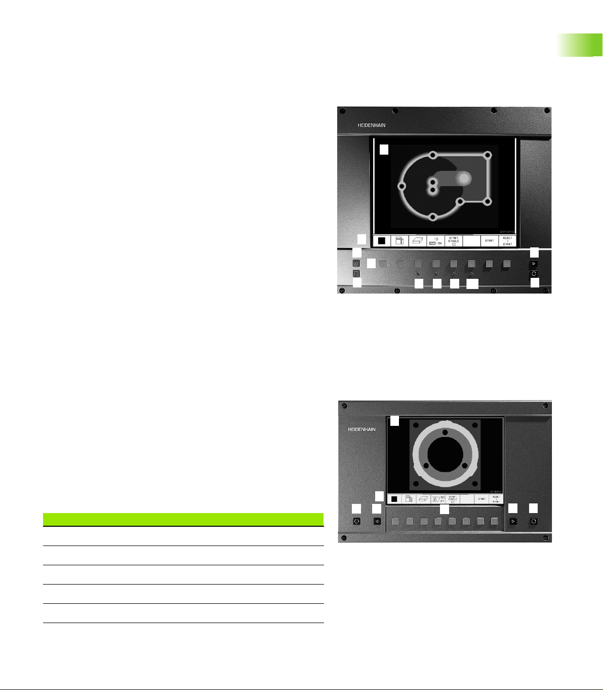
Visual display unit
The TNC 406 is delivered with the BC 110 color monitor (CRT); the
TNC 416 can be delivered with the BC 120 color monitor (CRT) or the
BF 120 flat-screen color monitor (TFT). The figure at top right shows
the keys and controls on the BC 120, and the figure at bottom right
shows those of the BF 120.
1 Header
When the TNC is on, the selected operating modes are shown in
the screen header.
2 Soft keys
In the footer the TNC indicates additional functions in a soft-key
row. You can select these functions by pressing the keys
immediately below them. The lines immediately above the softkey row indicate the number of soft-key rows that can be called
with the black arrow keys to the right and left. The line
representing the active soft-key row is highlighted.
3 Soft key selector keys
4 Switching the soft-key rows
5 Setting the screen layout
6 Shift key for switchover between machining and programming
modes
1
1
2
4
3
1
5
7
9
8
10
4
6
1
1.2 Visual Display Unit and Keyboard
Keys on BC 120 only
7 Screen demagnetization; Exit main menu for screen settings
8 Select main menu for screen settings:
In the main menu: Move highlight downward
In the submenu: Reduce value or move picture to the left or
downward
9 In the main menu: Move highlight upward
In the submenu: Increase value or move picture to the right or
upward
10 In the main menu: Select submenu
In the submenu: Exit submenu
5
1
Main menu dialog Function
BRIGHTNESS Adjust brightness
CONTRAST Adjust contrast
H-POSITION Adjust horizontal position
V-POSITION Adjust vertical position
V-SIZE Adjust picture height
HEIDENHAIN TNC 406, TNC 416 3
1
2
4
6
4
11
3
1
Page 25
Main menu dialog Function
SIDE-PIN Correct barrel-shaped distortion
TRAPEZOID Correct trapezoidal distortion
ROTATION Correct tilting
COLOR TEMP Adjust color temperature
R-GAIN Adjust strength of red color
B-GAIN Adjust strength of blue color
RECALL No function
The BC 110 and BC 120 are sensitive to magnetic and electromagnetic
noise, which can distort the position and geometry of the picture.
Alternating fields can cause the picture to shift periodically or to
become distorted.
Screen layout
You select the screen layout yourself: In the TEST RUN mode of
operation, for example, you can have the TNC show program blocks in
the left window while the right window displays programming
graphics. You could also display the tool status in the right window
1.2 Visual Display Unit and Keyboard
instead, or display only program blocks in one large window. The
available screen windows depend on the selected operating mode.
To change the screen layout:
Press the SPLIT SCREEN key: The soft-key row
shows the available layout options (see ”Modes of
Operation” on page 6).
Select the desired screen layout.
4 1 Introduction
Page 26
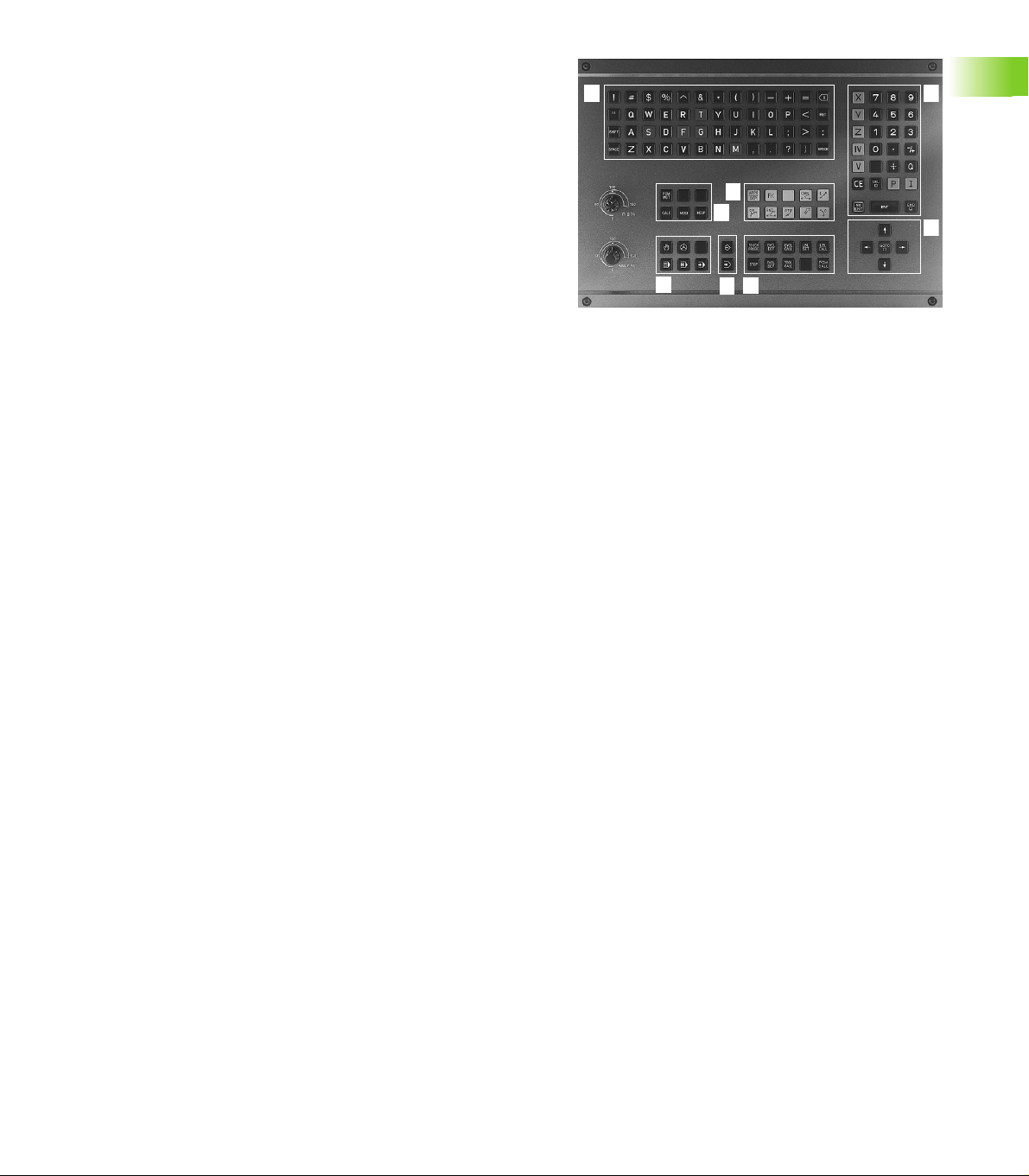
Keyboard
The figure at right shows the keys of the keyboard grouped according
to their functions:
1 Alphabetic keyboard for entering text and file names
2 File management
MOD functions
3 Programming modes
4 Machine operating modes
5 Initiation of programming dialog
6 Arrow keys and GOTO jump command
7 Numerical input and axis selection
The functions of the individual keys are described on the inside front
cover. Machine panel buttons, e.g. NC START, are described in the
manual for your machine tool.
1
5
2
1
4
1
5
3
7
6
1.2 Visual Display Unit and Keyboard
HEIDENHAIN TNC 406, TNC 416 5
Page 27
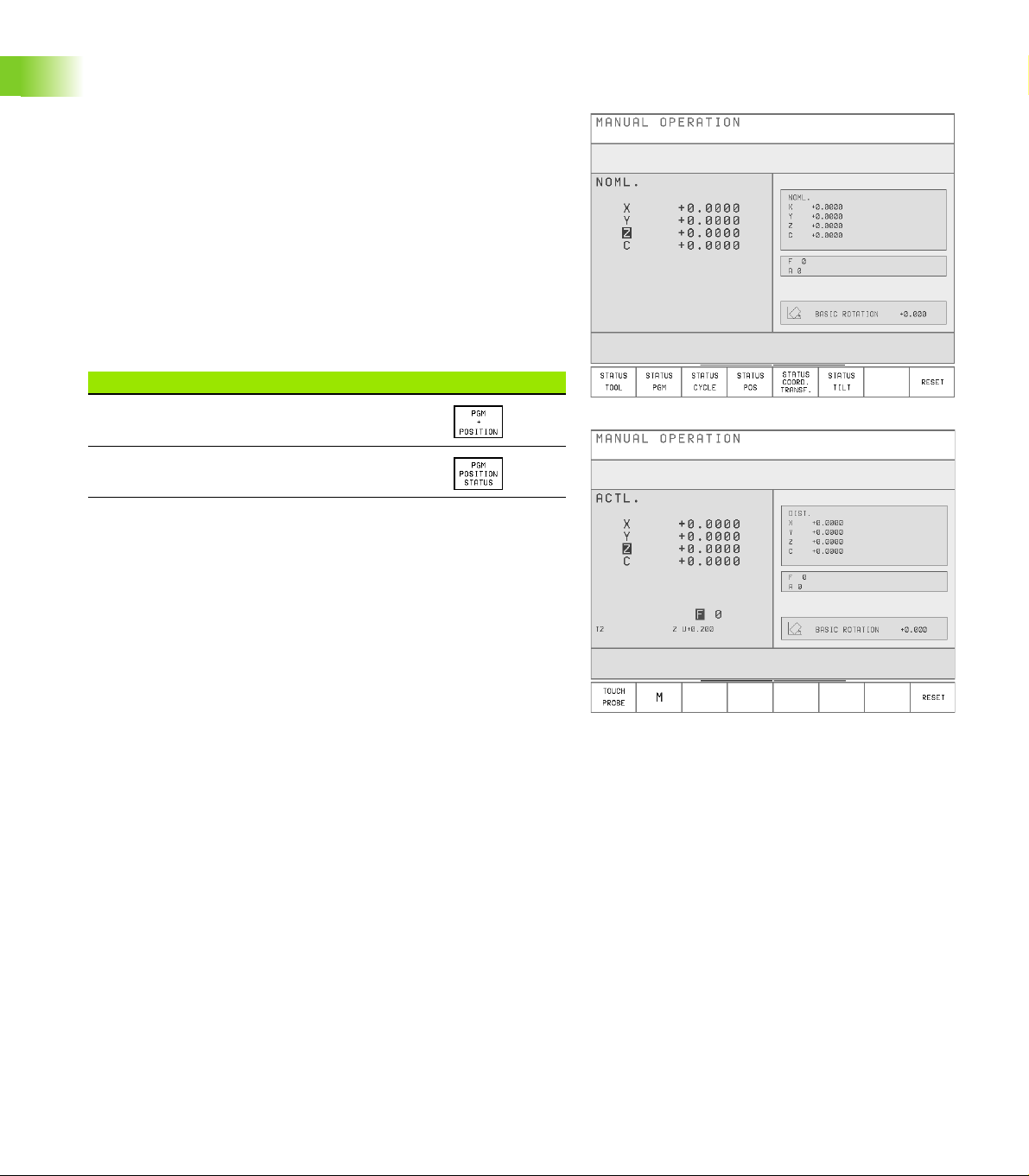
1.3 Modes of Operation
Manual Operation, Incremental Jog, and Positioning with Manual Data Input
The Manual Operation mode is required for setting up the machine
tool. In this mode of operation, you can position the machine axes
manually or by increments, set the datums, and tilt the working plane.
The Incremental Jog mode of operation allows you to move the
machine axes manually with the HR electronic handwheel.
Simple traverse movements can be programmed in the Positioning
with Manual Data Input (MDI) mode of operation.
Soft keys for selecting the screen layout (see ”Screen layout” on
page 4)
1.3 Modes of Operation
Screen windows Soft key
Positions
Left: positions. Right: status display.
6 1 Introduction
Page 28
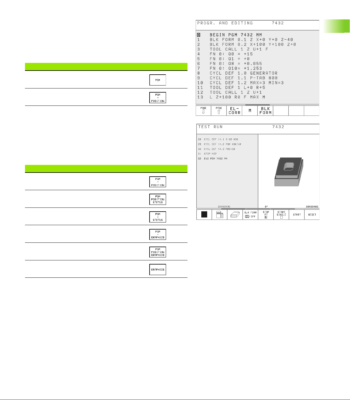
Programming and Editing
In this mode of operation you can write your part programs. The
various cycles and Q parameter functions help you with programming
and add necessary information.
Soft keys for selecting the screen layout
Screen windows Soft key
Top: program. Bottom: positions
Top left: program. Top right: status
Bottom: positions
Test Run
In the Test Run mode of operation, the TNC checks programs and
program sections for errors, such as geometrical incompatibilities, or
missing or incorrect data within the program. This simulation is
supported graphically in different display modes.
Soft keys for selecting the screen layout
Screen windows Soft key
Top: program. Bottom: positions
Top left: program. Top right: status
Bottom: positions
Left: program. Right: status
Left: program. Right: graphics
Top left: program. Top right: graphics
Bottom: positions
Graphics
1.3 Modes of Operation
HEIDENHAIN TNC 406, TNC 416 7
Page 29
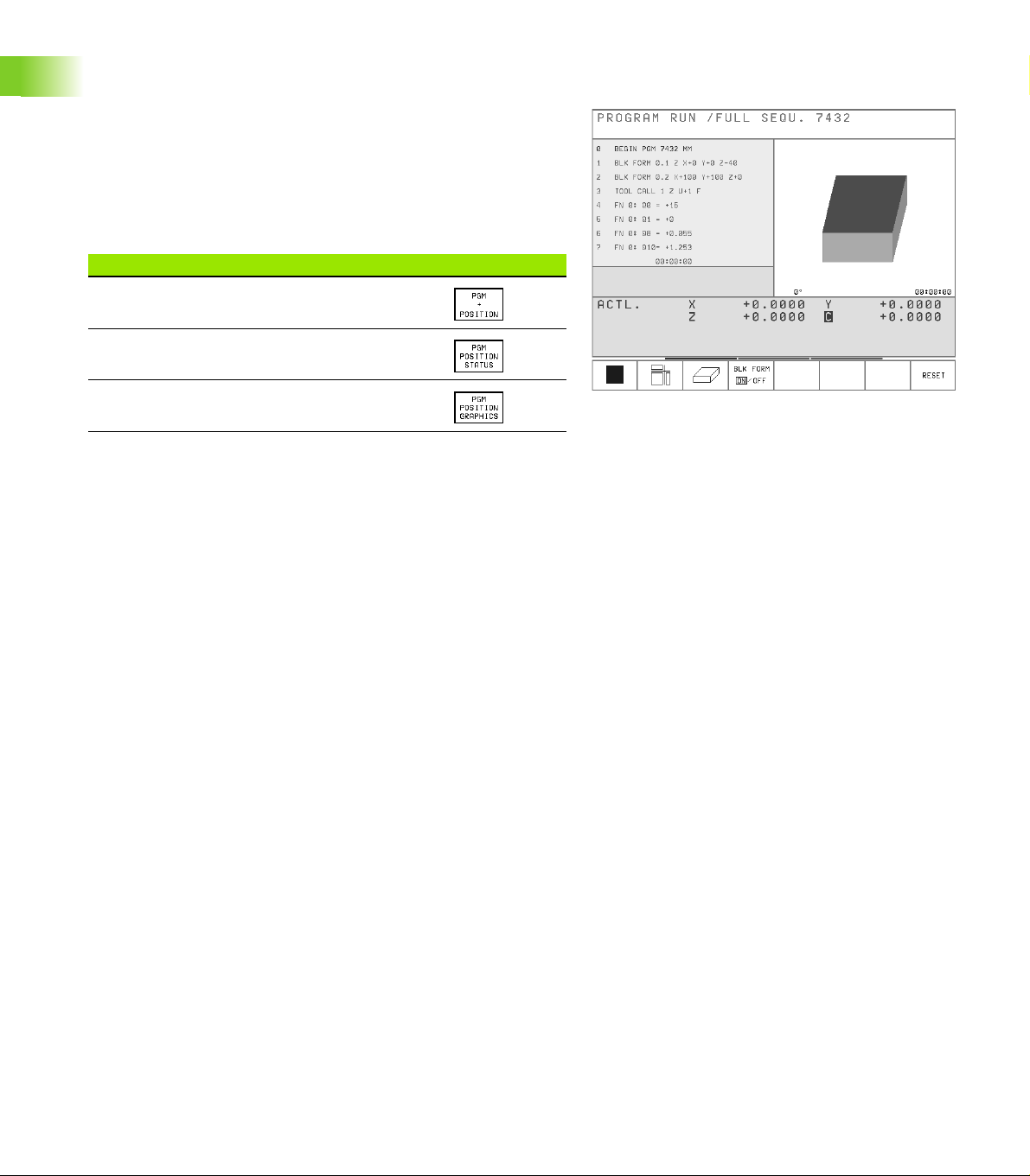
Program Run, Full Sequence and Program Run, Single Block
In the Program Run, Full Sequence mode of operation the TNC
executes a part program continuously to its end or to a manual or
programmed stop. You can resume program run after an interruption.
In the Program Run, Single Block mode of operation you execute each
block separately by pressing the machine START button.
Soft keys for selecting the screen layout
Screen windows Soft key
Top: program. Bottom: positions
Top left: program. Top right: status
1.3 Modes of Operation
Bottom: positions
Top left: program. Top right: graphics
Bottom: positions
8 1 Introduction
Page 30
1.4 Status Display
General status display
Besides the coordinates, the status display also contains the following
information:
Type of position display (ACTL, NOML, etc.)
Axis is locked ( on the axis)
Number of the current electrode T
Electrode axis
Feed rate F
Active miscellaneous functions M
TNC is in operation (indicated by )
Name of the selected erosion table
Permissible power stages (GENERATOR cycle)
Current power stage
Additional status displays
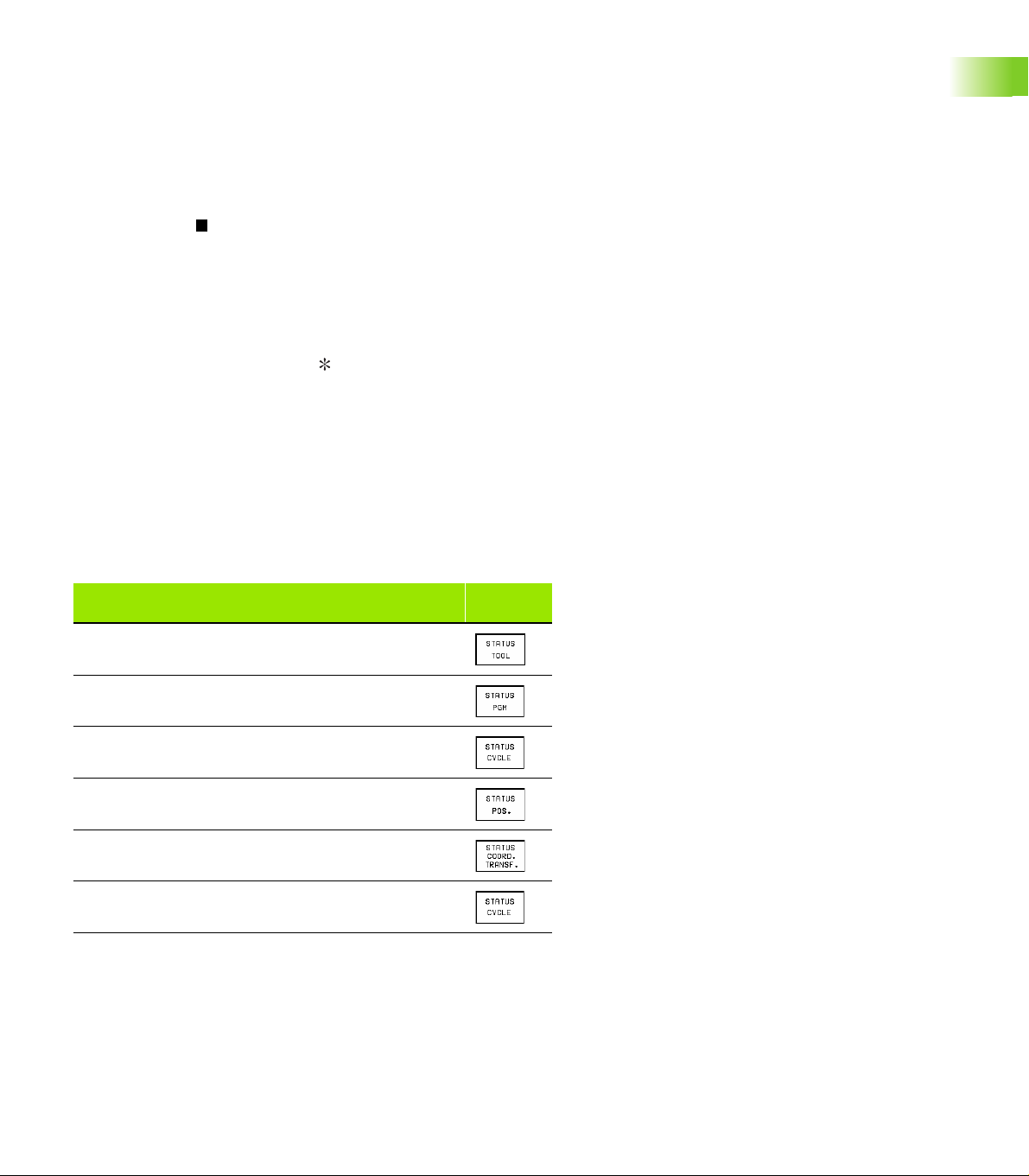
In all modes of operation (except PROGRAMMING AND EDITING),
you can split the screen layout to display additional status information
in the right screen window:
1.4 Status Display
Additional status display
Information on the current electrode
General program information
Information on the current OEM cycle
Positions and coordinates
Active coordinate transformations
Tilting the working plane
HEIDENHAIN TNC 406, TNC 416 9
Soft
keys
Page 31

Information on the current electrode
1 Electrode length
2 Electrode radius
3 Electrode undersize
4 Electrode axis
1.4 Status Display
General program information
1 Programs called with PGM CALL
2 Active cycle
3 Active circle center
4 Dwell time counter
5 Status for eroding with time limit
6 Operating time
1
2
3
4
1
2
3
4
5
10 1 Introduction
6
Page 32

Information on the current OEM cycle
1 Active OEM cycle (number and name)
2 Number of the transfer parameters
3 Content of each transfer parameter
Positions and coordinates
1 Second position display
2 Feed rate and angular position for Cycle 17 DISK
3 Active basic rotation
1
23
1.4 Status Display
1
2
3
HEIDENHAIN TNC 406, TNC 416 11
Page 33

Active coordinate transformations
1 Active datum table and active datum number
2 Datum shift
3 Rotation
4 Mirror image
5 Scaling factor
1
2
3
4
1.4 Status Display
Tilting the working plane
1 Active basic rotation
2 Active tilting angle
5
1
2
12 1 Introduction
Page 34

1.5 Accessory: Electronic
Handwheels from HEIDENHAIN
HR electronic handwheels
The electronic handwheels facilitate precise manual control of the axis
slides.
Similar to a conventional machine tool, you move the machine slide a
defined distance by turning the handwheel.
A wide range of traverses per revolution is available.
Portable handwheels, such as the HR 410, are connected via cable to
the TNC.
Integral handwheels, such as the HR 130, are built into the machine
control panel.
Your machine manufacturer can tell you more about the handwheel
configuration of your machine.
HEIDENHAIN TNC 406, TNC 416 13
1.5 Accessory: Electronic Handwheels from HEIDENHAIN
Page 35

Page 36

2
Manual Operation, Setup and Probing Functions
Page 37

2.1 Switch-on
Switch-on
Switch-on and traversing the reference points can vary
depending on the individual machine tool. Refer to your
machine manual.
2.1 Switch-on
Switch on the power supply for control and machine. The TNC
automatically initiates the following dialog
MEMORY TEST
The TNC memory is automatically checked.
POWER INTERRUPTED
TNC message that the power was interrupted —
clear the message.
TRANSLATE PLC PROGRAM
The PLC program of the TNC is automatically compiled.
RELAY EXT. DC VOLTAGE MISSING
Switch on external dc voltage. The TNC checks the
functioning of the EMERGENCY STOP circuit.
MANUAL OPERATION
TRAVERSE REFERENCE POINTS
Cross the reference points manually in the displayed
sequence: For each axis press the machine START
button, or
Cross the reference points in any sequence: Press
and hold the machine axis direction button for each
axis until the reference point has been traversed.
16 2 Manual Operation, Setup and Probing Functions
Page 38

The TNC is now ready for operation in the Manual Operation mode.
The reference points need only be traversed if the
machine axes are to be moved. If you intend only to write,
edit or test programs, you can select the Programming
and Editing or Test Run modes of operation immediately
after switching on the control voltage.
You can traverse the reference marks later by choosing
the Manual mode of operation.
2.1 Switch-on
HEIDENHAIN TNC 406, TNC 416 17
Page 39

2.2 Moving the Machine Axes
and
Note
The TNC shows the position of up to five machine axes.
The machine manufacturer can enable the position of the
fifth axis, for example with the machine axis-direction
buttons, with jog increments, with the electronic
handwheel or through ”PLC positioning”.
Contact your machine manufacturer if you need to
position a fifth axis.
To traverse with the machine axis direction buttons:
2.2 Moving the Machine Axes
Select the Manual Operation mode.
Press the machine axis-direction button and hold it as
long as you wish the axis to move, or
Move the axis continuously: Press and hold the
machine axis direction button, then press the
machine START button
To stop the axis, press the machine STOP button.
18 2 Manual Operation, Setup and Probing Functions
Page 40

Traversing with the HR 410 electronic
or
handwheel
The portable HR 410 handwheel is equipped with two permissive
buttons. The permissive buttons are located below the star grip.
You can only move the machine axes when an permissive button is
depressed (machine-dependent function).
The HR 410 handwheel features the following operating elements:
1 EMERGENCY STOP
2 Handwheel
3 Permissive buttons
4 Axis address keys
5 Actual-position-capture key
6 Keys for defining the feed rate (slow, medium, fast; the feed rates
are set by the machine tool builder)
7 Direction in which the TNC moves the selected axis
8 Machine function (set by the machine tool builder)
1
2
4
6
8
3
4
5
7
The red indicators show the axis and feed rate you have selected.
It is also possible to move the machine axes with the handwheel
during a program run.
To move an axis:
Select the Jog Increment mode.
Press and hold the permissive button.
Select the axis.
Select the feed rate.
Move the active axis in the positive or negative
direction.
2.2 Moving the Machine Axes
HEIDENHAIN TNC 406, TNC 416 19
Page 41

If short-circuit monitoring is active: When the electrode
makes sparking contact, the TNC stops positioning in the
direction of the workpiece, and only permits retracting in
the opposite direction. Also, the axes cannot be switched.
After they have been retracted at least 10 µm, the TNC
switches back to normal Handwheel operation mode.
This function is not active while the reference marks are
being traversed.
The axes can also be positioned with the electronic
handwheel in the PROGRAMMING AND EDITING mode.
You must set machine parameter MP7655=1.
Incremental jog positioning
With incremental jog positioning you can move a machine axis by a
preset distance.
Incremental Jog Positioning must be enabled by the
machine tool builder. Refer to your machine manual.
2.2 Moving the Machine Axes
Select the Jog Increment mode.
Z
INTERPOLATION FACTOR =
Enter interpolation factor, i.e. 4
Go to JOG INCREMENT.
JOG INCREMENT =
Enter the jog increment in millimeters, i.e. 8 mm.
The axis moves by the jog increment every time an
external axis-direction button is pressed.
Positioning with manual data input (MDI)
Positioning with manual input of the target coordinates is described in
Chapter 3 (see ”Positioning with Manual Data Input (MDI)” on page
38).
8 8
816
X
20 2 Manual Operation, Setup and Probing Functions
Page 42

Eroding a workpiece manually
The MANUAL and JOG INCREMENT modes of operation enable you
to erode a workpiece manually. This function is especially useful for
initial erosion and datum setting. The present gap must be taken into
account when setting the datum.
Prerequisite
Cycle 1 GENERATOR must be active.
Procedure
8 Select the MANUAL or JOG INCREMENT mode of operation.
8 Switch on the generator with M36
8 Use the axis direction buttons to preposition the electrode in the
working plane. During free run of the electrode, the manual feed
rate is effective.
8 Move the electrode with the axis direction button until it touches the
workpiece. Gap control becomes effective upon contact. The TNC
deduces the eroding direction from the axis direction button that
was last pressed.
In the MANUAL mode of operation, you can erode up to
the limit switch. In the JOG INCREMENT mode of
operation, the workpiece is eroded the preset distance.
During erosion you can only move the electrode in the
other axes by using the handwheel.
2.2 Moving the Machine Axes
8 To end the erosion process, press the machine axis-direction button
for the opposite direction.
HEIDENHAIN TNC 406, TNC 416 21
Page 43

2.3 Datum Setting
The production drawing identifies a certain form element of the
workpiece (usually a corner) as the absolute datum, and usually one or
more form elements as relative datums (see ”Setting the datum” on
page 47). Through the datum setting process, the origin of the
absolute or relative coordinate systems is set to these datums:
The workpiece – aligned to the machine axes – is brought into a certain
position relative to the electrode, and the display is set to zero or the
appropriate position value (i.e., to account for the electrode radius).
Example
2.3 Datum Setting
Coordinates of Point 1:
X = 10 mm
Y = 5 mm
Z = 0 mm
The datum of the rectangular coordinate system is located
negative 10 mm on the X axis and negative 5 mm on the Y axis from
Point 1.
The fastest, easiest and most accurate way of setting the datum is by
using the probing functions for datum determination.
Z
Y
X
Z
Y
X
1
5
10
22 2 Manual Operation, Setup and Probing Functions
Page 44

2.4 Calibration and Setup
Using an electrode
An electrode and the probing functions of the TNC 406 can
significantly reduce setup time. The TNC 406 offers the following
probing functions:
Compensation of workpiece misalignment
(Basic rotation)
Datum setting
Measuring
- lengths and positions on the workpiece
- angles
- circle radii
- circle centers
Measurements during program run
The TNC must be prepared by the machine tool builder
before the probing functions can be used.
In probing functions, the electrode starts moving after the external
START button is pressed. The machine tool builder determines the
feed rate F for movement towards the workpiece.
When the probing electrode touches the workpiece,
the TNC stores the coordinates of the probed position,
the probing electrode stops moving,
the probing electrode returns to its starting position in rapid
traverse.
2.4 Calibration and Setup
F
F
Machine parameter 6100 determines whether each
probing process is to be executed once or several times
(maximum number of probing processes: 5). If you wish to
probe several times, the TNC calculates the average of all
touch points. This average value is the probing result.
(See also ”Selecting the General User Parameters” on
page 246)
HEIDENHAIN TNC 406, TNC 416 23
F
max
Page 45

Select the touch probe function
Overview
The following probing functions are available in the Manual and Jog
Increment modes:
Function Soft key
Measuring a basic rotation using a line
Manual probing
Set the datum in any axis
Set the datum at a workpiece center
2.4 Calibration and Setup
Set the datum at a circle center
Set the datum at a corner
Select the calibration function for the electrode length
(second soft-key row)
Select the calibration function for the electrode radius
(second soft-key row)
Select the touch probe function
8 Select the Manual Operation or Jog Increment mode.
8 Select the probing function by pressing the TOUCH
PROBE soft key. The TNC displays additional soft
keys- see table above.
8 To select the probe cycle: press the appropriate soft
key, for example PROBING ROT, and the TNC
displays the associated menu.
24 2 Manual Operation, Setup and Probing Functions
Page 46

Calibrating the probing electrode
The probing electrode is to be calibrated in the following situations:
During commissioning
When the electrode is changed
When the probing feed rate is changed
In case of irregularities, such as those arising when the machine
heats up
During calibration, the TNC finds the effective length and the effective
radius of the electrode.
To calibrate the electrode, clamp a ring gauge of known height and
inside diameter to the machine table.
To calibrate the effective length:
8 Set the datum in the spindle axis such that for the machine tool table
Z=0.
8 Select the calibration function for the electrode length
(second soft-key row).
8 (QWHUWKHWRROD[LVZLWKWKHD[LVNH\
8 'DWXP(QWHUWKHKHLJKWRIWKHULQJJDXJH
8 Move the probing electrode to a position just above
the ring gauge.
8 ,IQHFHVVDU\FKDQJHWKHGLUHFWLRQZLWKWKHFXUVRU
NH\V
8 The electrode probes the surface of the ring gauge:
Press the START button.
2.4 Calibration and Setup
HEIDENHAIN TNC 406, TNC 416 25
Page 47

To calibrate the effective radius:
8 Position the probing electrode in the hole of the ring gauge.
8 Select the calibration function for the electrode radius
(second soft-key row).
8 Select the tool axis and enter the radius of the ring
gauge.
8 To probe the workpiece, press the machine START
button four times. The probing electrode touches the
hole in each axis direction.
8 If you want to terminate the calibration function at this
point, press the END soft key.
Z
Y
10
Displaying calibration values
The effective length and radius of the probing electrode are stored in
the TNC’s memory, and are taken into account when the electrode is
used later.
2.4 Calibration and Setup
The stored values are displayed on the screen whenever the
calibration functions are selected.
X
26 2 Manual Operation, Setup and Probing Functions
Page 48

Compensating workpiece misalignment
The TNC electronically compensates workpiece misalignment by
computing a ”basic rotation”.
For this purpose, the rotation angle is set to the desired angle with
respect to the reference axis in the working plane. If the tilt working
plane function is used, the TNC also takes the basic rotation into
account in the tilted system.
Measuring the basic rotation
8 Select probing function BASIC ROTATION.
8 Set ROTATION ANGLE to the nominal value.
8 Move the electrode to position A near the first probe
point 1.
8 Select the probe direction perpendicular to the angle
reference axis: Select the axis by soft key.
8 To probe the workpiece, press the machine START
button.
8 Move the electrode to position B near the second
probe point 2.
8 To probe the workpiece, press the machine START
button.
A basic rotation is stored in nonvolatile memory and is effective for all
subsequent program runs and graphic simulations.
Y
Y
2.4 Calibration and Setup
PA
X
A B
X
Displaying a basic rotation
The angle of the basic rotation is shown after ROTATION ANGLE. The
rotation angle is also shown in the additional status display window
whenever a basic rotation is active.
To cancel a basic rotation:
8 Select BASIC ROTATION again.
8 Enter a rotation angle of zero and confirm with the ENT key.
8 To terminate the probe function, press the END key.
HEIDENHAIN TNC 406, TNC 416 27
Page 49

2.5 Datum Setting with a
Probing Electrode
Functions for setting the datum
Function Soft key
Set the datum in any axis
Manual probing
Set the datum at a workpiece center
Set the datum at a circle center
Set the datum at a corner
After probing you can set a new datum or transfer the captured values
to a datum or tool table.
Writing probed values to tables
In order to write probed values to datum tables, the tables
2.5 Datum Setting with a Probing Electrode
The TNC writes the probed value to a table after the TRANSFER TO
TABLE soft key is pressed. You can choose a datum table (NAME.D)
as well as a tool table (NAME.T):
8 Select manual probing by pressing the TOUCH PROBE soft key.
8 Enter the name of the datum or tool table.
8 Enter the datum number or tool number.
8 Select the probing function and begin probing.
8 Press the TRANSFER TO TABLE soft key for the TNC to write the
probed value to the selected table.
Writing probed values to a table while a program is running
You can also write probed values to the TOOL table during program
run. Use miscellaneous function M109 to transfer the contents of the
Q parameters Q81 to Q84 into the table TOOL.T.
You can also use M108 to read the tool compensation values from the
TOOL table into parameters Q81 to Q84 (see also ”Q parameters for
the datum table: Q81 to Q84” on page 206).
28 2 Manual Operation, Setup and Probing Functions
must be active on your TNC (bit 2 in machine parameter
7224 = 0).
Page 50

Datum setting in any axis
8 Select the probing function by pressing the PROBING
POS soft key.
8 Move the touch probe to a starting position near the
touch point.
8 Select the probe axis and direction in which you wish
to set the datum, such as Z in direction Z–. Selection
is made via soft keys.
8 To probe the workpiece, press the machine START
button.
8 Datum: Enter the nominal coordinate and confirm your
entry with ENT.
Manual probing
The PROBING DEPTH function enables you to probe the workpiece as
often as desired in one axis. At the same time, you can move all
remaining axes with the electronic handwheel. This probing function
is particularly convenient for finding peaks and valleys.
In this process, the TNC always stores the last point of electrode
contact with the workpiece. You can end the probing process with the
CYCLE STOP button.
8 Select the probing function PROBING DEPTH.
8 Move the probing electrode to a starting position near the touch
point.
8 Set the axis traverse limit, i.e. the maximum permissible traverse of
the electrode in the probing axis, and confirm with ENT.
8 Select the probe axis and direction in which you wish to set the
datum, such as Z in direction Z–.
8 Start the probing process. The TNC moves the electrode in the
selected axis direction until it makes contact with the workpiece.
This coordinate is stored in the TNC memory.
The probing process is repeated until you end the probing function
with CYCLE STOP.
8 Use the electronic handwheel to move the electrode in any of the
remaining axes to be scanned for peaks or valleys.
8 Enter the nominal coordinate of the datum and confirm with ENT.
2.5 Datum Setting with a Probing Electrode
HEIDENHAIN TNC 406, TNC 416 29
Page 51

Workpiece center as datum
With the function PROBING CENTER, you can find the center of
square or rectangular workpieces and set the datum at that point. The
workpiece must be aligned paraxially to use this function.
8 Select the probing function by pressing the PROBING
CENTER soft key.
8 Move the probing electrode to a position near the first
touch point.
8 Select the probing direction via soft key, e.g. X+.
8 To probe the workpiece, press the machine START
button.
8 Move the probing electrode to a position near the
second touch point.
8 To probe the workpiece, press the machine START
button.
8 Enter the first coordinate of the datum, for example on
the X axis.
8 Repeat the process for the third and fourth touch
points on the second axis, for example on the Y axis.
8 Enter the second coordinate of the datum, for
example on the Y axis.
8 End the probing function.
Z
Y
l
X
1
2
2.5 Datum Setting with a Probing Electrode
30 2 Manual Operation, Setup and Probing Functions
Page 52

Corner as datum
8 To select the probe function, press PROBING P.
8 Move the probing electrode to a position near the first
touch point.
8 Select the probing direction via soft key, e.g. X+.
8 To probe the workpiece, press the machine START
button.
8 Position the probing electrode near the second touch
point on the same side.
8 To probe the workpiece, press the machine START
button.
8 Probe two points on the next edge in the same
manner.
8 Datum: Enter both datum coordinates into the menu
window, and confirm your entry with the ENT key.
8 To terminate the probe function, press the END key.
Y=?
Y
P
X=?
Y
P
X
X
HEIDENHAIN TNC 406, TNC 416 31
2.5 Datum Setting with a Probing Electrode
Page 53
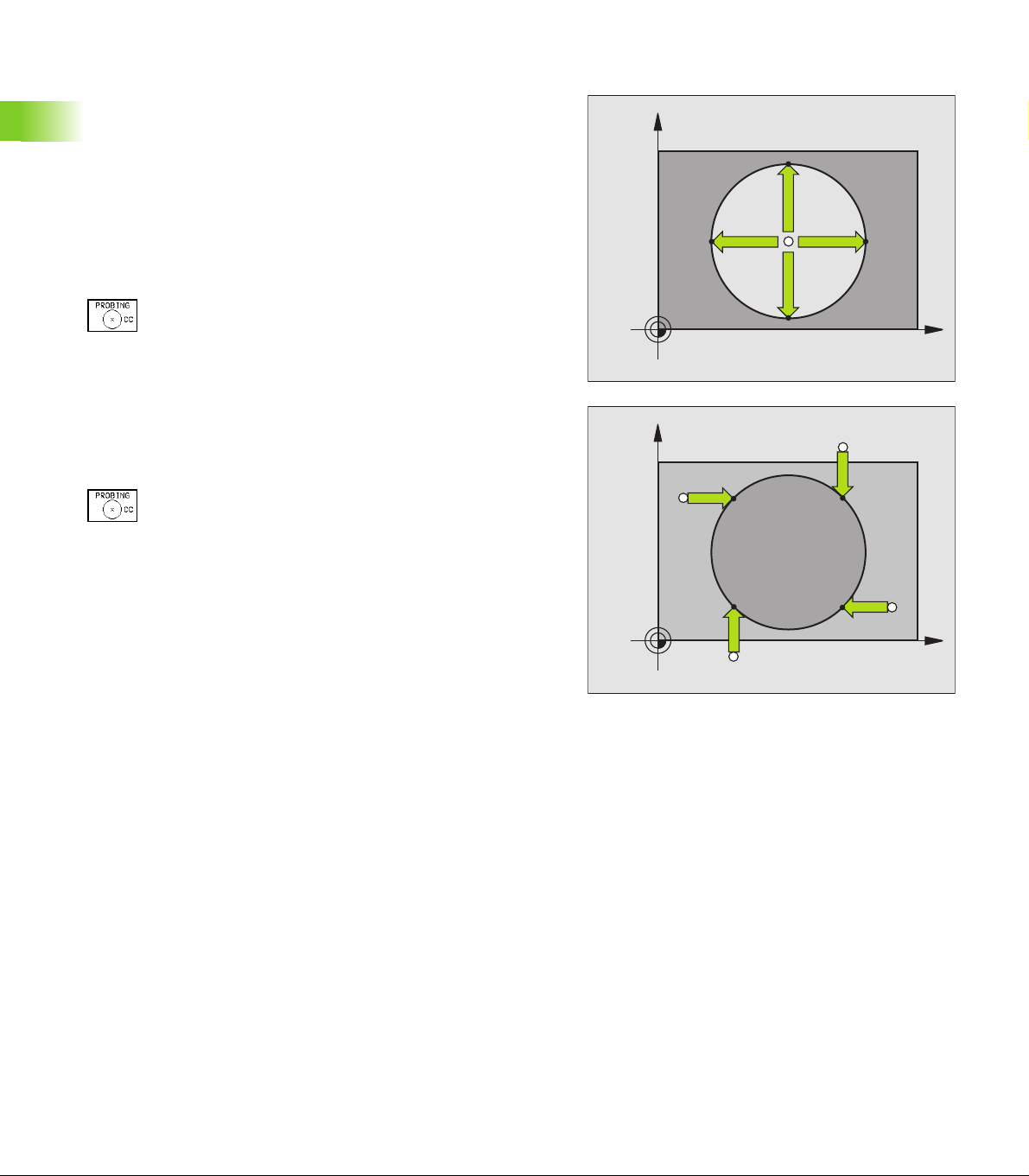
Circle center as datum
With this function, you can set the datum at the center of bore holes,
circular pockets, cylinders, studs, circular islands, etc.
Inside circle
The TNC automatically probes the inside wall in all four coordinate axis
directions.
For incomplete circles (circular arcs) you can choose the appropriate
probing direction.
8 Move the electrode to a position approximately in the center of the
circle.
8 To select the probe function, press PROBING CC.
8 To probe the workpiece, press the machine START
button four times. The touch probe touches four
points on the inside of the circle.
8 Datum: Enter both circle center coordinates into the
menu window, and confirm your entry with ENT.
8 To terminate the probe function, press the END key.
Outside circle
8 To select the probe function, press PROBING CC.
8 Move the probing electrode to a position near the first
touch point outside of the circle.
8 Select the probe direction with a soft key.
8 To probe the workpiece, press the machine START
2.5 Datum Setting with a Probing Electrode
After the probing procedure is completed, the TNC displays the
coordinates of the circle center and the circle radius PR on the
monitor.
button.
8 Repeat the probing process for the remaining three
points. See figure at lower right.
8 Enter the coordinates of the circle center.
Y
Y+
X+X–
Y–
X
Y
Y–
X+
X–
Y+
X
32 2 Manual Operation, Setup and Probing Functions
Page 54

2.6 Measuring with a
Probing Electrode
Introduction
An electrode can be used to determine
position coordinates, and from them,
dimensions and angles on the workpiece.
To find the coordinate of a position on an aligned workpiece
8 Select the probing function by pressing PROBING
POS.
8 Move the probing electrode to a starting position near
the touch point.
8 Select the probe direction and axis of the coordinate.
Use the corresponding soft keys for selection.
8 To probe the workpiece, press the machine START
button.
The TNC shows the coordinates of the touch point as datum.
Finding the coordinates of a corner in the working plane
Find the coordinates of the corner point as described under ”Corner
as datum”.
The TNC displays the coordinates of the probed corner as datum.
2.6 Measuring with a Probing Electrode
HEIDENHAIN TNC 406, TNC 416 33
Page 55

Measuring workpiece dimensions
8 Select the probing function by pressing PROBING
POS.
8 Move the probing electrode to a position near the first
touch point 1.
8 Select the probing direction with a soft key.
8 To probe the workpiece, press the machine START
button.
8 If you will need the current datum later, write down
the value that appears in the Datum display.
8 Set the datum to 0.
8 To terminate the dialog, press the END key.
8 Select the touch probe function again:
Press PROBING POS.
8 Move the probing electrode to a position near the
second touch point 2.
8 Select the probe direction with the soft keys: Same
axis but from the opposite direction.
8 To probe the workpiece, press the machine START
button.
The value displayed as DATUM is the distance between the two
points on the coordinate axis.
2.6 Measuring with a Probing Electrode
To return to the datum that was active before the length
measurement:
8 Select the probing function by pressing PROBING POS.
8 Probe the first touch point again.
8 Set the DATUM to the value that you wrote down previously.
8 To terminate the dialog, press the END key.
Z
Y
l
X
1
2
34 2 Manual Operation, Setup and Probing Functions
Page 56

Measuring angles
You can also use the probing electrode to measure angles in the
working plane. You can measure
the angle between the angle reference axis and a workpiece side, or
the angle between two sides.
The measured angle is displayed as a value of maximum 90°.
To find the angle between the angle reference axis and a side of
the workpiece
8 Select the probing function by pressing the PROBING
ROT soft key.
8 Rotation angle: If you will need the current basic
rotation later, write down the value that appears
under Rotation angle.
8 Make a basic rotation with the side of the workpiece
(see ”Compensating workpiece misalignment” on
page 27).
8 Press the PROBING ROT soft key to display the angle
between the angle reference axis and the edge of the
workpiece as the rotation angle.
8 Cancel the basic rotation, or restore the previous basic
rotation by setting the Rotation angle to the value that
you wrote down previously.
To measure the angle between two workpiece sides:
8 Select the probing function by pressing the PROBING ROT soft key.
8 Rotation angle: If you will need the current basic rotation later, write
down the value that appears under Rotation angle.
8 Make a basic rotation with the side of the workpiece (see
”Compensating workpiece misalignment” on page 27).
8 Probe the second side as for a basic rotation, but do not set the
Rotation angle to zero!
8 Press the PROBING ROT soft key to display the angle PA between
the two sides as the Rotation angle.
8 Cancel the basic rotation, or restore the previous basic rotation by
setting the Rotation angle to the value that you wrote down
previously.
100
Y
–10
PA
2.6 Measuring with a Probing Electrode
Z
L?
α?
X
α?
100
HEIDENHAIN TNC 406, TNC 416 35
Page 57

2.7 Entering and Starting
Miscellaneous Functions M
Entering values
Miscellaneous function M
To enter the miscellaneous function, press the M soft
key.
MISCELLANEOUS FUNCTION M =
6
The machine tool builder determines which miscellaneous
functions M are available on your TNC and what
function they have. Refer to your machine manual.
2.7 Entering and Starting Miscellaneous Functions M
Enter a miscellaneous function, e.g. M6.
Start the miscellaneous function.
36 2 Manual Operation, Setup and Probing Functions
Page 58

3
Positioning with Manual Data Input (MDI)
Page 59

3.1 Positioning with Manual Data
Input (MDI)
The POSITIONING WITH MANUAL DATA INPUT mode of operation is
particularly convenient for simple machining operations or exact prepositioning of the electrode. You can write a program in conversational
programming and execute it immediately. You can also define and call
TNC cycles. The program is stored in the file $MDI.
PGM CALL can not be used to call a program.
LBL CALL can not be used for calling sub-routines or
repeating sections of programs.
For a TOOL CALL block to processed, the
corresponding TOOL DEF tool definition must be
programmed within the $MDI file.
Incremental positionings always refers to the present
electrode position.
Programming a radius compensation (RL/RR) is not
permitted.
Positioning with manual data input (MDI)
Select the Positioning with MDI mode of operation.
Program the file $MDI as you wish.
3.1 Positioning with Manual Data Input (MDI)
Example: Programming and processing a line
38 3 Positioning with Manual Data Input (MDI)
To start program run, press the machine START button.
Select operating mode: Positioning with MDI.
Select the axis, and enter the end-point coordinates
of the line and the feed rate,
i.e.: L X+125 R F100 M
Conclude entry.
Start positioning block.
Page 60

Protecting and erasing programs in $MDI
74523
The $MDI file is generally intended for short programs that are only
needed temporarily. Nevertheless, you can store a program, if
necessary, by proceeding as described below:
Select the Programming and Editing mode of
operation.
To call the file manager, press the PGM MGT key
(program management).
Move the highlight to the $MDI file.
To select the file copying function, press the COPY
soft key.
TARGET FILE =
Enter the name under which you want to save the
current contents of the $MDI file.
End the copying process with the ENT key.
Erasing the contents of the $MDI file is done in a similar way: Instead
of copying the contents, however, you erase them with the DELETE
soft key. The next time you select the operating mode Positioning with
MDI, the TNC will display an empty $MDI file.
If you wish to delete $MDI, then
you must not have selected the Positioning with MDI
mode.
you must not have selected the $MDI file in the
Programming and Editing mode.
HEIDENHAIN TNC 406, TNC 416 39
3.1 Positioning with Manual Data Input (MDI)
Page 61

Page 62

4
Programming: Fundamentals, Files, Program Entry, Spark Erosion, Erosion Tables
Page 63

4.1 Fundamentals of Positioning
Introduction
This chapter covers the following topics:
What is NC?
The part program
Programming
Position encoders and reference marks
Reference system
Reference system with electrical discharge machines (EDM)
Programming electrode movement
Polar coordinates
Absolute and incremental workpiece positions
Setting the datum
What is NC?
NC stands for Numerical Control, that is, the operation of a machine
4.1 Fundamentals of Positioning
tool by a series of coded instructions comprised of numbers.
Modern controls such as TNCs have a built-in computer for this
purpose and are therefore called CNC (Computerized Numerical
Control).
The part program
The part program is a complete list of instructions for machining a part.
It contains such information as the target position of an electrode
movement, the path function (how the electrode should move toward
the target position) and the feed rate.
Information on the radius and length of the electrode and the electrode
axis must also be included in the program.
Programming
Conversational programming is a particularly easy method of writing
and editing part programs.
HEIDENHAIN NCs were developed specifically for the machine
operator who keys in programs right at the machine. This is why they
are called TNC (Touch Numerical Control).
You begin each machining step by pressing a key. The TNC then asks
you for all the information it needs to execute the step.
42 4 Programming: Fundamentals, Files, Program Entry, Spark Erosion, Erosion Tables
Page 64

Position encoders and reference marks
The machine axes are equipped with position encoders that register
the positions of the machine table or tool. When a machine axis
moves, the corresponding position encoder generates an electrical
signal. The TNC evaluates this signal and calculates the precise actual
position of the machine axis.
If there is an interruption of power, the calculated position will no
longer correspond to the actual position of the machine slide. The TNC
can re-establish this relationship with the aid of reference marks when
power is returned. The scales of the position encoders contain one or
more reference marks that transmit a signal to the TNC when they are
crossed over. From the signal the TNC identifies that position as the
machine-axis reference point and can re-establish the assignment of
displayed positions to machine axis positions.
Linear encoders are generally used for linear axes. Rotary tables and
tilt axes have angle encoders. If the position encoders feature
distance-coded reference marks, you only need to move each axis a
maximum of 20 mm (0.8 in.) for linear encoders, and 20° for angle
encoders, to re-establish the assignment of the displayed positions to
machine axis positions.
X
MP
X (Z,Y)
Z
Y
Reference system
A reference system is required to define positions in a plane or in
space. The position data are always referenced to a predetermined
point and are described through coordinates.
The Cartesian coordinate system (a rectangular coordinate system) is
based on the three coordinate axes X, Y and Z. The axes are mutually
perpendicular and intersect at one point called the datum. A
coordinate identifies the distance from the datum in one of these
directions. A position in a plane is thus described through two
coordinates, and a position in space through three coordinates.
Coordinates that are referenced to the datum are referred to as
absolute coordinates. Relative coordinates are referenced to any other
known position (datum) you define within the coordinate system.
Relative coordinate values are also referred to as incremental
coordinate values.
X
4.1 Fundamentals of Positioning
Z
Y
X
HEIDENHAIN TNC 406, TNC 416 43
Page 65

Reference system with EDMs
When using an EDM, you orient tool movements to the Cartesian
coordinate system. The illustrations at right show how the Cartesian
coordinate system describes the machine axes. The figure at center
right illustrates the ”right-hand rule” for remembering the three axis
directions: the middle finger is pointing in the positive direction of the
tool axis from the workpiece toward the tool (the Z axis), the thumb is
pointing in the positive X direction, and the index finger in the positive
Y direction.
The TNC 406/TNC 416 can control up to 5 axes. The axes U, V and W
are secondary linear axes parallel to the main axes X, Y and Z,
respectively. Rotary axes are designated as A, B and C. The illustration
at lower right shows the assignment of secondary axes and rotary
axes to the main axes.
Programming electrode movement
Depending on the machine tool, either the machine table with the
workpiece moves or the electrode moves.
You always program as if the electrode moves and the
4.1 Fundamentals of Positioning
If the machine table moves, the corresponding axes are identified on
the machine operating panel with a prime mark (e.g., X’, Y’). The
programmed direction of such axis movement always corresponds to
the direction of electrode movement relative to the workpiece but in
the opposite direction.
workpiece remains stationary, no matter the type of
machine.
+Y
+Z
+X
+Z
+Y
+X
+X
Z
Y
W+
C+
B+
V+
A+
X
U+
44 4 Programming: Fundamentals, Files, Program Entry, Spark Erosion, Erosion Tables
Page 66

Polar coordinates
If the production drawing is dimensioned in Cartesian coordinates, you
also write the part program using Cartesian coordinates. For parts
containing circular arcs or angles it is often simpler to give the
dimensions in polar coordinates (see „Path Contours — Polar
Coordinates” on page 109).
While the Cartesian coordinates X, Y and Z are three-dimensional and
can describe points in space, polar coordinates are two-dimensional
and describe points in a plane. Polar coordinates have their datum at a
circle center (CC), or pole. A position in a plane can be clearly defined
by the:
Polar Radius, the distance from the circle center CC to the position,
and the
Polar Angle, the size of the angle between the reference axis and
the line that connects the circle center CC with the position.
See figure at upper right.
Definition of pole and angle reference axis
The pole is set by entering two Cartesian coordinates in one of the
three planes. These coordinates also set the reference axis for the
polar angle PA.
Coordinates of the pole (plane) Reference axis of the angle
X/Y +X
10
Z
Y
R
H
2
H
3
R
CC
R
H
1
0°
X
30
Y
4.1 Fundamentals of Positioning
Y/Z +Y
Z/X +Z
Z
Y
X
Z
Y
X
X
HEIDENHAIN TNC 406, TNC 416 45
Page 67

Absolute and incremental workpiece positions
Absolute workpiece positions
Absolute coordinates are position coordinates that are referenced to
the datum of the coordinate system (origin). Each position on the
workpiece is uniquely defined by its absolute coordinates.
Example 1: Holes dimensioned in absolute coordinates
Hole 1 Hole 2 Hole 3
X = 10 mm X = 30 mm X = 50 mm
Y = 10 mm Y = 20 mm Y = 30 mm
Incremental workpiece positions
Incremental coordinates are referenced to the last programmed
nominal position of the tool, which serves as the relative (imaginary)
datum. When you write a part program in incremental coordinates,
you thus program the tool to move by the distance between the
previous and the subsequent nominal positions. Incremental
coordinates are therefore also referred to as chain dimensions.
To program a position in incremental coordinates, enter the prefix "I"
before the axis.
4.1 Fundamentals of Positioning
Example 2: Holes dimensioned in incremental coordinates
Absolute coordinates of hole 4
X = 10 mm
Y = 10 mm
Hole 5, referenced to 4 Hole 6, referenced to 5
X = 20 mm X = 20 mm
Y = 10 mm Y = 10 mm
Absolute and incremental polar coordinates
Absolute polar coordinates always refer to the pole and the reference
axis.
Incremental polar coordinates always refer to the last programmed
nominal position of the tool.
30
20
10
10
10 10
Y
3
1
2
1
1
1
X
3010
50
Y
6
1
5
1
4
1
X
10
20
20
Y
+IPR
PR
10
PR
+IPA
+IPA
CC
PA
PR
0°
X
30
46 4 Programming: Fundamentals, Files, Program Entry, Spark Erosion, Erosion Tables
Page 68

Setting the datum
The production drawing identifies a certain form element of the
workpiece (usually a corner) as the absolute datum, and usually one or
more form elements as relative datums. Through the datum setting
process, the origin of the absolute or relative coordinate systems is set
to these datums: The workpiece – aligned to the machine axes – is
brought into a certain position relative to the electrode, and the display
is set to zero or the appropriate position value (i.e., to account for the
electrode radius) (see „Datum Setting” on page 22).
Example
The workpiece drawing at right shows holes (1 to 4) whose
dimensions are shown with respect to an absolute datum with the
coordinates X=0, Y=0. The holes (5 to 7) are dimensioned with respect
to a relative datum with the absolute coordinates X=450, Y=750. With
the DATUM SHIFT cycle you can temporarily set the datum to the
position X=450, Y=750, to be able to program the holes (5 to 7)
without further calculations.
Z
Y
MAX
X
MIN
750
320
Y
4.1 Fundamentals of Positioning
150
7
1
0
6
1
-150
5
1
0,1
±
300
1
1
325
3
1
0
2
1
450 900
950
4
1
X
HEIDENHAIN TNC 406, TNC 416 47
Page 69

4.2 Files
The TNC 416 saves programs and tables as files. The TNC can store
up to 100 files. A file is identified by its file name and file extension.
4.2 Files
The file name is entered when a new file is created.
The file extension is separated from the file name by a period, and
indicates what type of file it is.
Files in the TNC Ty p e
Programs
In HEIDENHAIN format .H
Tables for
Erosion
Datum
Tools
Time capture
The tool table TOOL.T is only active if bit 2 of MP7224 is
set to 0.
File directory
You call the file directory with the PGM NAME key (TNC 406) or the
PGM MGT key (TNC 416).
To delete files from the TNC, use CL PGM on the TNC 406 to call up
the directory.
Overview of the file management functions:
.E
.D
.T
Time.W
File
... Create or
... Edit or
... Delete or
... Test or
... Run or
48 4 Programming: Fundamentals, Files, Program Entry, Spark Erosion, Erosion Tables
Operating
mode
Call file directory with
Page 70

The file directory contains the following information:
Display Meaning
FILE NAME Name (up to 8 characters plus file extension)
BYTE File size in bytes
STATUS
R
E
P
I
STORAGE AREA
AND NUMBER
INTERNAL
FILES
EXTERNAL FILES
Files in ROM
Pressing the ROM soft key displays files that the machine tool builder
wrote and stored in ROM, such as erosion tables. These files can be
edited.
Identification of protected files
The TNC inserts a ”P” in the first and last lines of write- and eraseprotected files.
The file directory also shows a ”P” next to the file name.
Properties of the file:
File is active for Program Run/Program Test.
File is active for Programming and Editing.
File is protected against editing and erasure.
Dimensions are given in inches.
Files in the TNC memory
Files, e.g., on a PC 401
4.2 Files
HEIDENHAIN TNC 406, TNC 416 49
Page 71

Selecting, copying, deleting and protecting files
Activate the file directory
8 Use the PGM MGT key with the TNC 416, and the PGN NAME key
with the TNC 406. If you want to delete files with the TNC 406, you
4.2 Files
must call the file directory with the CL PGM key.
Select the file
8 Enter the file name (not for CL PGM) or move the highlight with the
cursor keys to the desired file.
Function Soft key
Go to the next page
Go to the previous page
Display files in ROM
Select file (such as for a test run)
Copy file: Enter the name of the target file
File protection
Cancel file protection
Deleting a file
Close the file directory
50 4 Programming: Fundamentals, Files, Program Entry, Spark Erosion, Erosion Tables
Page 72

4.3 Creating and Writing Programs
Organization of an NC program in HEIDENHAIN conversational format.
A part program consists of a series of program blocks. The figure at
right illustrates the elements of a block.
The TNC numbers the blocks in ascending sequence.
The first block of a program is identified by BEGIN PGM, the program
name and the active unit of measure.
The subsequent blocks contain information on:
The workpiece blank
Tool definitions, tool calls
Feed rates and spindle speeds, as well as
Path contours, cycles and other functions
The last block of a program is identified by END PGM, the program
name and the active unit of measure.
Defining the blank form–BLK FORM
Immediately after initiating a new program, you define a cuboid
workpiece blank. If you wish to define the blank at a later stage, press
the BLK FORM soft key. This definition is needed for the TNC’s
graphic simulation feature. The sides of the workpiece blank lie parallel
to the X, Y and Z axes and can be up to 30 000 mm long. The blank
form is defined by two of its corner points:
MIN point: the smallest X, Y and Z coordinates of the blank form,
entered as absolute values.
MAX point: the largest X, Y and Z coordinates of the blank form,
entered as absolute or incremental values.
Blocks
10 L X+10 Y+5 R0 F100 M3
Path function
Block number
Z
Y
MAX
Words
4.3 Creating and Writing Programs
X
You only need to define the blank form if you wish to run
a graphic test for the program!
MIN
HEIDENHAIN TNC 406, TNC 416 51
Page 73

Creating a new part program
0
You always enter a part program in the Programming and Editing
mode of operation. Program initiation in an example:
Select the Programming and Editing mode of
operation.
Press the key to call the file directory.
FILE NAME = 7432
Enter the new program name and confirm your entry
with the ENT key.
Choose the type of file: Press the .H, .E or .D soft key.
The TNC changes to the program window.
4.3 Creating and Writing Programs
WORKING SPINDLE AXIS X/Y/Z ?
DEF BLK FORM: MIN-CORNER ?
0
-40
DEF BLK FORM: MAX-CORNER ?
100
100
0
To define the BLK-FORM, press the BLK-FORM soft
key. The TNC opens a dialog for defining the
BLK FORM.
Enter the spindle axis.
Enter in sequence the X, Y and Z coordinates of the
MIN point.
Enter in sequence the X, Y and Z coordinates of the
MAX point.
52 4 Programming: Fundamentals, Files, Program Entry, Spark Erosion, Erosion Tables
Page 74

Example: Display the BLK form in the NC program.
0 BEGIN PGM NEW MM
1 BLK FORM 0.1 Z X+0 Y+0 Z-40
2 BLK FORM 0.2 X+100 Y+100 Z+0
3 END PGM NEW MM
The TNC automatically generates the block numbers as well as the
BEGIN and END blocks.
If you do not wish to define a blank form, cancel the dialog
at Working spindle axis X/Y/Z by pressing the DEL key!
The TNC can display the graphic only if the ratio of the
short side to the long sides of the BLK FORM is greater than
1:64!
Program begin, name, unit of measure
Spindle axis, MIN point coordinates
MAX point coordinates
Program end, name, unit of measure
4.3 Creating and Writing Programs
HEIDENHAIN TNC 406, TNC 416 53
Page 75

Programming tool movements in conversational
20
3
format
To program a block, initiate the dialog by pressing a function key. In the
screen headline, the TNC then asks you for all the information
necessary to program the desired function.
Example of a dialog
Dialog initiation
COORDINATES ?
10
RADIUS COMP. RL/RR/NO COMP. ?
4.3 Creating and Writing Programs
FEED RATE ? F= / F MAX = ENT
100
MISCELLANEOUS FUNCTION M ?
6
The program blocks window will display the following line:
3 L X+10 Y+20 R0 F100 M36
Enter the target coordinate for the X axis.
Enter the target coordinate for the Y axis, and go to
the next question with ENT.
Enter ”No radius compensation” and go to the next
question with ENT.
Enter a feed rate of 100 mm/min for this path contour;
go to the next question with ENT.
Enter the miscellaneous function M36 ”eroding ON”;
pressing the ENT key terminates this dialog.
54 4 Programming: Fundamentals, Files, Program Entry, Spark Erosion, Erosion Tables
Page 76

Function Key
Continue the dialog
Ignore the dialog question
End the dialog immediately
Abort the dialog and erase the block
Editing a program
While you are creating or editing a part program, you can select any
desired line in the program or individual words in a block with the
arrow keys or the soft keys:
Function Soft keys/keys
Go to the previous page
Go to the next page
Move from one block to the next
Select individual words in a block
Function Key
Set the selected word to zero
Erase an incorrect number
Clear a (non-blinking) error message
Delete the selected word
Delete the selected block
Erase cycles and program sections: First
select the last block of the cycle or program
section to be erased, then erase with the DEL
key.
4.3 Creating and Writing Programs
HEIDENHAIN TNC 406, TNC 416 55
Page 77

Inserting blocks at any desired location
8 Select the block after which you want to insert a new block and
initiate the dialog.
Editing and inserting words
8 Select a word in a block and overwrite it with the new one. The plain-
language dialog is available while the word is highlighted.
8 To accept the change, press the END key.
If you want to insert a word, press the horizontal arrow key repeatedly
until the desired dialog appears. You can then enter the desired value.
Looking for the same words in different blocks
To select a word in a block, press the arrow keys
repeatedly until the highlight is on the desired word.
Select a block with the arrow keys.
Select a block directly.
4.3 Creating and Writing Programs
The word that is highlighted in the new block is the same as the one
you selected previously.
56 4 Programming: Fundamentals, Files, Program Entry, Spark Erosion, Erosion Tables
Page 78
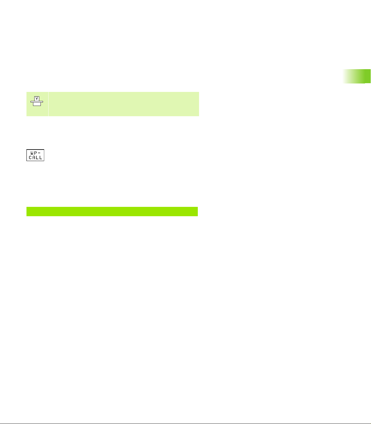
4.4 Automatic Workpiece Change
with WP-Call
If your machine features an automatic handling system, you can
program an automatic workpiece change with the WP-CALL function.
WP-CALL resets an active rotation, and can be programmed to
subsequently execute a datum shift and activate the rotation again, if
desired. The values for datum shift and rotation are transferred by the
PLC.
The function for automatic workpiece change is adapted to
the TNC by the machine tool builder. Refer to your
machine tool manual.
Programming a workpiece change
8 Select the Programming and Editing mode of operation.
8 Press the WP-CALL soft key.
8 Workpiece name: Enter the name of the pallet
(for example, 1). You can enter up to 16 characters
(letters and numbers).
8 Number of tilts: Enter the number of tilts (maximum
input value: 9).
Example NC block
7 WP–CALL 1 / 1
HEIDENHAIN TNC 406, TNC 416 57
4.4 Automatic Workpiece Change with WP-Call
Page 79

4.5 Fundamentals of Spark Erosion
Electrical discharge machining is an electrothermal process which
uses a spark to remove metal by melting and vaporizing (”eroding”)
the workpiece surface.
In contrast, cutting machine tools such as milling machines remove
metal by direct abrasive action.
The spark erosion process is described on the following pages.
The electrode (e) and the workpiece (w) are submerged in a dielectric
fluid (d).
A generator applies a voltage to the electrode and the workpiece (both
the electrode and the workpiece are then electrodes).
An electric field is then created in the gap between the electrode and
the workpiece.
The electric field is strongest where the gap is the smallest.
The electrically conductive particles in the dielectric fluid are
concentrated at this point.
4.5 Fundamentals of Spark Erosion
I
d
e
W
+
U
+
A bridge of electrically conductive particles forms between the
electrode and the workpiece.
+
58 4 Programming: Fundamentals, Files, Program Entry, Spark Erosion, Erosion Tables
Page 80

After a certain length of time (the ignition delay time), a discharge
channel suddenly forms across the bridge of particles, and current
starts to flow between the electrode and the workpiece. The current
flow increases the temperature in the discharge channel, and further
electrically charged particles are created (ions). The current increases.
The temperature in the discharge channel becomes so great that the
dielectric fluid there vaporizes.
+
+
4.5 Fundamentals of Spark Erosion
The discharge channel expands in the middle while at the electrode
and workpiece it becomes narrower.
The temperature increases to a point where the surfaces of the
electrode and workpiece melt. Part of the molten metal vaporizes.
+
HEIDENHAIN TNC 406, TNC 416 59
Page 81

When the voltage is removed, the discharge channel collapses
(implodes).
When the discharge channel collapses, the implosion thrusts the
molten metal into the dielectric fluid.
4.5 Fundamentals of Spark Erosion
+
+
A small crater remains on the electrode and the workpiece. The debris
of melted electrode or workpiece material remains suspended in the
dielectric fluid.
+
60 4 Programming: Fundamentals, Files, Program Entry, Spark Erosion, Erosion Tables
Page 82

4.6 Erosion Tables
The machine tool builder can define the erosion tables as
required. He may also define additional parameters that
are not mentioned in your TNC manual. Refer to your
machine tool manual.
The spark erosion process is influenced by process variables called
erosion parameters. You can enter the erosion parameters for a
machining sequence in erosion tables for the TNC 406/416.
For example, you can create a separate erosion table for each
combination of electrode and workpiece material.
All parameters are then clearly grouped in this table. The TNC can
access the parameters for a particular machining sequence.
Using erosion tables in a program
If you want to work with erosion tables in a program, you must copy
Cycle 1 (GENERATOR) into the program (see „Cycle 1 GENERATOR”
on page 133). In this cycle you declare what erosion table you are
working with.
Working without an erosion table
It is also possible to work without an erosion table. In this case the
TNC stores the erosion parameters in the Q parameters Q90 to Q99
(see „Preassigned Q parameters” on page 202). Your machine manual
provides more information on these Q parameters.
4.6 Erosion Tables
Ready-to-use erosion tables
The machine builder can prepare erosion tables and store them in the
TNC’s ROM. Proceed as follows if you want to work with these
erosion tables:
8 Press the PGM NAME key in the PROGRAMMING AND EDITING
mode of operation.
8 Press the ROM soft key.
The machine tool builder can give you additional information on these
erosion tables.
HEIDENHAIN TNC 406, TNC 416 61
Page 83

4.7 Parameters in the Erosion Table
You can enter the following erosion parameters in one erosion table:
Meaning Range
Power stage (NR) 25 to 1
Low voltage current (LV) 0 to 99
High voltage current (HV) 0 to 9
Gap voltage (GV) 0 to 99
Pulse-on duration (TON) 0 to 999
Pulse-off duration (TOFF) 0 to 255
Servo sensitivity (SV) 0 to 99 %
Auto jump distance (AJD) 0 to 99.9 mm
Erosion time (ET) 0 to 999 s
Arc sensitivity (AR) 0 to 99
Electrode polarity (P) 0 or 1
4.7 Parameters in the Erosion Table
High voltage selector (HS) 0 to 99
Wear rate (WR) 0 to 99 %
Surface finish (RA) 0 to 99.9 µm
Stock removal (SR) 0 to 999.999 ccm/min
Two-times gap (2G) 0 to 9.999 mm
Minimum undersize (UNS) 0 to 9.999 mm
Auxiliary parameters (AUX 1 to AUX 6)
62 4 Programming: Fundamentals, Files, Program Entry, Spark Erosion, Erosion Tables
Page 84

To enter erosion parameters in the erosion table
Activate file management.
FILE NAME ?
Select a file with the arrow keys.
15
PROGRAM SELECTION
POWER STAGE NUMBER
1
The TNC then asks for all further erosion parameters described in this
chapter.
To enter erosion parameters for additional power stages
Enter the file name directly, e.g. 15. For a new erosion
table you must enter the name.
Open the selected erosion table.
Select program type .E (erosion table).
Enter the number of the power stage for the following
data. Confirm with ENT.
With INSERT, erosion parameters for up to 25 power
stages can be entered.
4.7 Parameters in the Erosion Table
To conclude entry
Return to program management with PGM NAME.
To go to a certain power stage
Use GOTO to directly access a certain power stage number in the
erosion table (do not enter the table row number).
Unit of measurement in the table
With the TAB soft key you can change the name of the table and the
unit of measurement. The same unit (millimeters or inches) should be
used in the erosion tables as in the NC program.
HEIDENHAIN TNC 406, TNC 416 63
Page 85

Power stage (NR)
The power stages determine the type of machining (roughing,
finishing or polishing).
Recommended input
Roughing NR = 15 to 10
Finishing NR = 10 to 6
Fine finishing NR = 6 to 1
Polishing NR = 5
Input range
15 (25) to 1 in decreasing order.
To change the power stage in the program
The current power stage is given by Q parameter Q99.
If you change Q99, you also change the power stage.
Low voltage current (LV)
The machine tool builder can give you information on this
4.7 Parameters in the Erosion Table
Input range
0 to 99 in up to 100 increments.
erosion parameter. Refer to your machine tool manual.
High voltage current (HV)
The machine tool builder can give you information on this
erosion parameter. Refer to your machine tool manual.
Input range
0 to 9 in up to 10 increments.
Gap voltage (GV)
The TNC adjusts the width of the gap between the electrode and the
workpiece by controlling the gap voltage. The nominal gap voltage GV
should be chosen with care.
Setting
If the gap voltage is too high, the rate of stock removal will be too
low.
If the gap voltage is too low, irregularities will occur (arcing, short
circuiting).
64 4 Programming: Fundamentals, Files, Program Entry, Spark Erosion, Erosion Tables
Page 86

Pulse-on duration and pulse-off duration
The pulse-on duration (TON) is the time in which the generator
applies a voltage to the electrode and workpiece.
Ignition and subsequent discharge take place during this time.
The pulse-off duration (TOF) is the time in which no voltage is
generated.
During this time the gap is flushed and deionized.
Select the TON/TOF ratio according to the type of machining:
Setting
Roughing: Long pulse-on duration, short pulse-off duration
Finishing and polishing: Short pulse-on duration, long pulse-off
duration
Servo sensitivity SV
The machine tool builder specifies a characteristic curve
for servo sensitivity (see figure center right). Refer to your
machine tool manual.
The servo sensitivity influences the reaction speed of the gap control.
Setting
High servo sensitivity: fast gap control
Low servo sensitivity: slow gap control
1
2
F
U
U
T- ON TF
T- ON TF
SV= 99
SV= 60
U gap
t
t
4.7 Parameters in the Erosion Table
Input range
0 to 99 %
Erosion time ET, Auto jump distance AJD
The erosion time determines how long an erosion step lasts. When
the programmed erosion time has run out, the electrode retracts by
the auto jump distance and subsequently returns to the position
given in machine parameter MP2051.
Intermittent flushing
To improve deionization of the gap and flush away debris, you can
activate miscellaneous function M8 (intermittent flushing ON).
HEIDENHAIN TNC 406, TNC 416 65
ET
ET
AJD
AJD
MP 2051
Page 87

Arc sensitivity (AR)
The arc sensitivity setting influences the gap signal that the generator
sends to the TNC. The characteristic curve shows the nominal speed
value plotted against the gap voltage.
The machine tool builder can give you information on this
erosion parameter. Refer to your machine tool manual.
Electrode polarity (P)
To minimize wear on the electrode and ensure a high rate of stock
removal, you must set the correct electrode polarity.
Input value
Positive electrode: 0
Negative electrode: 1
If you mount the electrode on the machine table, you must
change the electrode polarity defined in the machine table.
The TNC does not reverse the polarity automatically.
4.7 Parameters in the Erosion Table
High voltage selector HS
The high voltage is the voltage that the generator applies to the
electrode and workpiece.
Setting
High value for HS:
For large gaps and for high rate of stock removal.
Low value for HS (with ignition pulse):
For small gaps and for low rate of stock removal.
Low value for HS (without ignition pulse):
For a few specific hard metals and very small electrodes.
HS
U
T- ON
t
66 4 Programming: Fundamentals, Files, Program Entry, Spark Erosion, Erosion Tables
Page 88

Wear rate WR
The wear rate is the ratio between the volume of material removed
from an electrode (Ve) and the volume of material removed from the
workpiece (Vw).
WR = Ve / Vw • 100 %
For the wear rate on the electrode for your particular machining task
and combination of materials, refer to the electrode table.
Surface finish RA
Surface finish is a measure of machining quality. A machined surface
is never absolutely smooth, but consists of a series of peaks and
valleys.
Ve
Vw
4.7 Parameters in the Erosion Table
Maximum surface roughness R
max
The maximum surface roughness Rmax is the difference in height
between the highest peak and the lowest valley.
The maximum surface roughness Rmax is also calculated from the
width of the two-times gap 2G and the minimum undersize UNS as
follows:
R
= 0.5 • ( UNS – 2G )
max
Determining surface finish RA according to VDI 3400
1 Determine the centerline of R
max
2 Measure all peaks and valleys from the centerline
3 Add the measured values together and divide by the number of
measured values. The result is the surface finish RA in [µm]
R
max
R2 R3 R4
RA
R1
max
min
Rn
HEIDENHAIN TNC 406, TNC 416 67
Page 89

Stock removal SR
The stock removal is the volume of removed workpiece material (Vw)
per unit of time.
Stock removal is measured in ccm/minute.
Two-times gap (2G)
During the erosion process, a minimum gap G must be maintained
between the electrode and the workpiece. The higher the current, the
larger the gap (G = radial gap) can (and should) be.
4.7 Parameters in the Erosion Table
Minimum for the two-times gap
The two-times gap 2G is the minimum total gap (2 x G in millimeters)
that must be maintained in the cavity between the electrode and the
workpiece (2G = diametrical gap).
R
max
Vw
R
G
G
max
68 4 Programming: Fundamentals, Files, Program Entry, Spark Erosion, Erosion Tables
Page 90

Minimum undersize (UNS)
The electrode diameter (Re) must be smaller than the cavity diameter
by at least the value of the minimum undersize UNS.
Roughing
For roughing, the minimum undersize UNS is calculated from the
two-times gap 2G and the maximum surface roughness R
Finishing and polishing
For finishing and polishing, the minimum undersize UNS is equal to
the two-times gap 2G. (The maximum surface roughness R
be disregarded.)
max
max
.
can
UM
2
R
max
G
UNS
=
2
Selecting the actual undersize UM
For a simple cavity (movement only in the electrode axis):
UNS = UM
For contour eroding and eroding with DISC cycle
(movement of the electrode in all axes): UM ≥ UNS
Auxiliary parameters AUX 1, AUX 2, ... AUX 6
The machine tool builder can assign functions to up to six
auxiliary parameters. Refer to your machine tool manual.
e
4.7 Parameters in the Erosion Table
HEIDENHAIN TNC 406, TNC 416 69
Page 91

Page 92

5
Programming: Tools
Page 93

5.1 Electrodes
Each electrode is identified by a number.
The electrode data, consisting of the
Length L
Radius R
are assigned to the electrode number.
5.1 Electrodes
The electrode data are entered into the program with the TOOL DEF
command.
The TNC takes the electrode length and radius into account when the
electrode is called by its number.
If you are working with standard electrodes you can also define all the
electrode data in a separate program.
In the part program you then call the program containing the electrode
definitions with the PGM CALL command.
Electrode axis C
You can define the C axis as the electrode axis.
The TNC then operates as if the Z axis were the electrode axis. This
also holds for radius compensation and for the ROTATION cycle.
Determining the electrode data
Electrode number
Each electrode is assigned a number from 0 to 99 999 999.
Electrode number 0 is defined as having length L = 0 and radius R = 0
when the electrode data are entered into the program.
Electrode radius R
The radius of the electrode is entered directly.
Electrode length L
The compensation value for the electrode length is defined
as a length difference between the electrode and a zero electrode,
or
with a tool presetter.
If electrode lengths are determined with a tool presetter they should
be entered directly into the electrode definition (TOOL DEF block)
without further conversions.
72 5 Programming: Tools
Page 94

Determining the electrode length with a zero electrode
Sign of the electrode length L:
L>L0: The tool is longer than the zero tool
L<L0: The tool is shorter than the zero tool
To determine the length:
8 Move zero electrode to the reference position in electrode axis
(such as workpiece surface with Z = 0).
8 If necessary, set datum in electrode axis to zero.
8 Insert electrode.
8 Move electrode to the same reference position as zero electrode.
8 The compensation value for length L of the electrode is displayed.
8 Write down the value and enter it later, or transfer the value with the
actual position capture function.
Entering electrode data into a program
For each electrode the electrode data can be entered once in the part
program:
Electrode number
Electrode length compensation value L
Electrode radius R
To enter the electrode data into a program block
The number, length and radius of a specific electrode is defined in the
TOOL DEF block of the part program.
8 To select tool definition, press the TOOL DEF key.
8 Tool number : Assign a number to the electrode
8 Tool length : Compensation value for the tool length
8 Tool radius : Compensation value for the tool radius
T
N
T
1
T
2
5.1 Electrodes
Z = 0
L = 0
L
L +
The electrode length L can be transferred directly into
the electrode definition with the actual position capture
function (see ”Actual Position Capture” on page 84).
Cycle 3 TOOL DEF (see ”Cycle 3 TOOL DEF” on page
135) deletes the tool length from the TOOL DEF(inition)!
Example
4 TOOL DEF 5 L+10 R+5
HEIDENHAIN TNC 406, TNC 416 73
Page 95

Entering electrode data in tables
You can define and store up to 999 tools and their tool data in a tool
table. You can assign a pocket number in the tool magazine to the
tools.
With MP7261 you can limit the number of pockets in the
tool magazine. There is no limiting if MP7261=0.
Setting MP7265=1 prevents multiple assignment of a
5.1 Electrodes
Tool table: Standard tool data
Abbr. Input Dialog
NR Number by which the tool is called in the program (e.g. 5) Tool number ?
PT Pocket number in the tool magazine Pocket number?
U Tool undersize (diametrical) Tool undersize? (diametrical)
X Tool compensation value for the X axis Tool compensation?
Y Tool compensation value for the Y axis Tool compensation?
Z Tool compensation value for the Z axis Tool compensation?
C Tool compensation value for the C axis Tool compensation?
R Compensation value for the tool radius R Tool radius R?
pocket number.
Tool undersize from the table is only active if you do not
define it again during TOOL CALL.
Editing tool tables
The tool table that is active during execution of the part program is
designated TOOL.T. It can only be edited in the Programming and
Editing mode. Other tool tables that are used for archiving or test runs
are given different file names with the extension .T .
To open any other tool table:
8 Select the Programming and Editing mode of operation.
8 Call the program directory.
8 Choose the desired TOOL table, and confirm your
choice with the ENT key or with the SELECT soft key.
When you have opened the tool table, you can edit the tool data by
moving the cursor to the desired position in the table with the arrow
keys or the soft keys. You can overwrite the stored values, or enter
new values at any position. The available editing functions are
illustrated in the table below.
74 5 Programming: Tools
Page 96

If the TNC cannot show all positions in the tool table in one screen
page, the highlight bar at the top of the table will display the symbol
”>>” or ”<<”.
Exiting the tool table
8 Call the file manager and select a file of a different type, e.g. a part
program.
Editing functions for tool tables Soft key
Insert new line above the highlighted field
Delete line
Create new TOOL table by entering a new name
5.1 Electrodes
HEIDENHAIN TNC 406, TNC 416 75
Page 97

Calling electrode data
Electrode data are called into the part program with TOOL CALL.
TOOL CALL is programmed with
Tool number
Spindle axis
Undersize
Code indicating whether the electrode is a following electrode
5.1 Electrodes
You can skip individual entries with NO ENT, for example to enter only
one (new) undersize.
Calling electrode data
8 Select the tool call function with the TOOL CALL key.
8 Tool number: Enter the number of the electrode as
defined in TOOL DEF block. Confirm your entry with
the ENT key.
8 Working tool axis X/Y/Z/4: Enter the tool axis, e.g.
Z.
8 Tool undersize (diameter): Enter the electrode
undersize (diameter), e.g. 0.5. Confirm with the ENT
key or
skip the entry with the NOENT key.
8 Folw. electrode YES=ENT/NO=NOENT: e.g., to identify
the electrode as a following electrode.
If you define a value for the tool undersize in the TOOL
CALL, the value from the TOOL table is ignored.
Otherwise the undersize from the TOOL table is valid.
Example: Electrode call
Call electrode number 5 in the tool axis Z.
The diametrical electrode undersize is + 0.5 mm.
20 TOOL CALL 5 Z U+0.5 F
76 5 Programming: Tools
Page 98

Following electrode
Answering ”YES” to FOLW. ELECTRODE prevents the workpiece
from being damaged by too large an amount of taper (caused by
insufficient flushing or deep mold cavities) during roughing operations
at high current. For the gap between the electrode and the workpiece
the TNC multiplies the minimum gap by the value in Q157.
The value in Q157 is determined by your answer to FOLW.
ELECTRODE.
Call with following electrode: finishing, small undersize (narrow gap):
Q157 = 1
Call without following electrode: roughing, large undersize (wide gap):
1< Q157 < 2.5
Changing the electrode
The electrode can be changed automatically or manually.
Automatic electrode change with EL-CALL
The function for automatic electrode change is adapted to
the TNC by the machine tool builder. Refer to your
machine tool manual.
If your machine features an automatic handling system, you can
program an automatic electrode change with the EL-CALL function.
EL-CALL combines the functions TOOL DEF and TOOL CALL.
8 Select the Programming and Editing mode of operation.
8 Select the EL-CALL function with the EL-CALL soft
key.
8 Electrode name: Enter the name of the electrode, e.g.
1. You can enter up to 16 characters (letters and
numbers). Confirm your entry with the ENT key.
8 Working tool axis X/Y/Z/4: Enter the tool axis.
8 Folw. electrode YES=ENT/NO=NOENT:
e.g., to identify the electrode as a following electrode.
Example
5.1 Electrodes
4 EL-CALL 1 /ZF
To ensure that the TNC shifts the electrode correctly to
the programmed position, you must enter the correct
C axis coordinates in a traversing block with L,
programmed directly after the EL-CALL block.
HEIDENHAIN TNC 406, TNC 416 77
Page 99

Manual electrode change
Before a manual electrode change, you must move the electrode to a
changing position. Course of actions:
Interrupt program run (see ”Interrupting machining” on page 223)
Move the electrode to the change position (can be programmed)
Change electrode
Resume the program run (see ”Resuming program run after an
interruption” on page 225)
5.1 Electrodes
Electrode change position
The electrode change position must be capable of being approached
without collision next to or over the workpiece.
The coordinates of the change position can also be entered as
machine-based coordinates with miscellaneous functions M91 and
M92.
If TOOL CALL 0 is programmed before the first electrode call, the TNC
moves the clamping shaft in the spindle axis to a position that is
independent of the electrode length.
Electrode compensation
You can compensate the electrode length and radius in a separate
program block.
8 Select the Programming and Editing mode of operation.
8 Select the EL-CORR function with the EL-CORR soft
key.
8 Undersize comp: Enter the undersize compensation.
Confirm your entry with the ENT key.
8 Electrode length comp:
Enter the electrode length compensation value.
Confirm your entry with the ENT key.
If no electrode length compensation: Press the NO
ENT key.
8 Electrode radius comp:
Enter the electrode radius compensation value.
Confirm your entry with the ENT key.
If no electrode radius compensation: Press the NO
ENT key.
Example
4 EL-CORR U+1 L R+0.5
Effect on Q parameters
The EL CORR block influences the pre-assigned Q parameters Q108,
Q158 and Q159 (see also ”Electrode data: Q108, Q158 to Q160” on
page 203).
78 5 Programming: Tools
Page 100

5.2 Electrode Compensation Values
For each electrode, the TNC takes the compensation value for the
electrode length into account for the electrode axis. In the working
plane, it compensates the electrode radius.
Electrode length compensation
The compensation value for the electrode length goes into effect
automatically as soon as an electrode is called and the spindle axis is
moved.
The compensation value for the electrode length is cancelled by calling
an electrode with length L = 0.
If a positive length compensation was active before TOOL
CALL 0, the distance to the workpiece will be reduced.
If the electrode axis is positioned incrementally
immediately following a TOOL CALL, then in addition to
the programmed value the length difference between the
old and new electrodes will also be traversed.
5.2 Electrode Compensation Values
HEIDENHAIN TNC 406, TNC 416 79
 Loading...