

Page 1

Technical Information
¬
NC Software 286 02x xx
zadsnnn
Page 2

Contents
1 Specifications 1–1
2 Components 2–4
3 Mounting and Electrical Installation 3–6
3.1 Electrical Noise Immunity 3–6
3.2 Heat Generation and Cooling 3–7
3.3 Humidity 3–7
3.4 Mechanical Vibration 3–7
3.5 Degree of Protection 3–7
3.6 Mounting Position 3–8
3.7 Connection Overview 3–10
3.7.1 LE 370 D 3–10
3.7.2 Power Supply 3–11
3.7.3 Measuring System Inputs 3–13
3.7.4 Reference Signal for the Spindle 3–14
3.7.5 Supply voltage for "Control-is-ready" 3–14
3.7.6 Analog Nominal Value Output 3–15
3.7.7 Switching Inputs 24 Vdc for the PLC 3–17
3.7.8 Switching Outputs 24 Vdc for the PLC 3–20
3.7.9 Machine Operating Panel 3–23
3.7.10 TNC Keyboard 3–24
3.7.11 Visual Display Unit 3–26
3.7.12 PLC input/output unit PL 410 B/ PL 405 B 3–27
3.7.13 Touch Trigger Probes 3–28
3.7.14 RS-232-C/V.24 Data Interface 3–31
3.7.15 Handwheel Input 3–32
3.7.16 Analog Inputs 3–37
3.8 Visual Display Unit BF 370 B 3–40
3.9 Mounting Dimensions 3–41
3.10 Cable overview 3–44
3.11 Grounding plan 3–45
4.1 What Is a Machine Parameter? 4–47
4.2 Input and Output of Machine Parameters 4–48
4.2.1 Input Format 4–48
4.2.2 Activating the Machine Parameter Settings 4–48
4.2.3 Changing the Input Values 4–49
4.3 List of Machine Parameters 4–52
4.3.1 Encoders and Machine 4–52
4.4 Positioning 4–57
4.5 Operation with Velocity Feedforward 4–59
4.6 Operation with Servo Lag 4–60
4.7 Main Spindle 4–60
4.8 Integrated PLC 4–64
July 02 Specifications TNC 370 D 1–1
Page 3

4.9 Adaptation of the Data Interfaces 4–66
4.10 3-D Touch Probe 4–67
4.11 Tool Measurement with TT 130 4–68
4.12 Tapping 4–70
4.13 Display and Operation 4–71
4.14 Machining and Program Run 4–75
4.15 Hardware 4–79
5 List of Markers and Words 5–81
5.1 List of Markers 5–81
5.2 List of Words 5–85
6 List of Modules 6–88
1–2 TNC 370 D Specifications July 02
Page 4

1 Specifications
Axes 3 or 4 and spindle S;
All axes can be defined as NC or PLC axes
Program memory 128 KB (64 NC programs with a total of approx. 6000 blocks)
Input resolution and
display step
Interpolation
Linear interpolation 3 of 4 axes
Circular interpolation 2 of 4 axes
Helix Superimposition of circular arcs and straight lines
Tapping without
floating tap holder
Block processing time2) 6 ms
Axis control Velocity feedforward control;
Position control
resolution
Cycle time path
interpolation
Error compensation · Linear axis error
Data interface RS–232–C/ V.24, max. 115 200 baud
1) This function must be implemented by the machine manufacturer.
2) 3-D straight lines without radius compensation
1 µm for linear axes
0.001 degrees for rotary axes
Yes
1)
Operation with servo lag
Fehler!
6 ms
· Multipoint axis error
· Backlash
· Reversal spikes during circular motion
· Thermal expansion
· Offset
July 02 Specifications TNC 370 D 1–1
Page 5
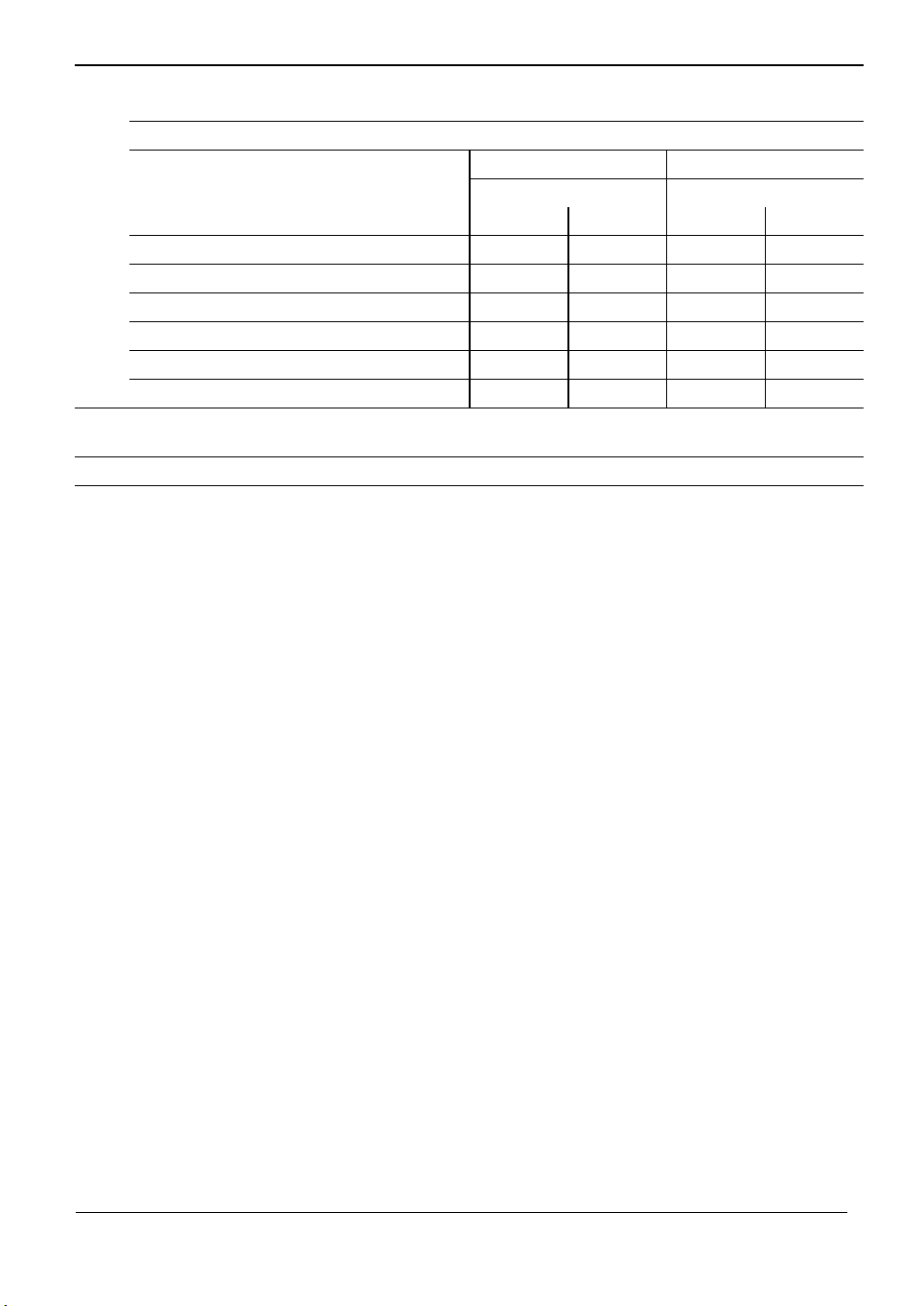
Integral PLC
PLC memory Approx. 8 000 commands
PLC cycle time 24 ms
LE LE + PL 410 B LE + 2 PL 410 B
Analog input PT 100 Analog input PT 100
without with without with
PLC inputs 24 Vdc 56 119 119 183 183
PLC outputs 24 Vdc 31 62 62 93 93
Analog inputs ± 10 V 3 (option) – 7 – 11
Inputs for PT100 thermistors 2 (option) – 6 – 10
"Control-is-ready" signal output 1 2 3
"Control-is-ready" signal input 1 1 1
Power supply for logic
Power supply for PLC
400 Vac ± 10 %
24 Vdc
Weight 6 kg
1–2 TNC 370 D Specifications July 02
Page 6

User Functions
Program input In HEIDENHAIN conversational programming and according to ISO
Position data Nominal positions in Cartesian or polar coordinates, dimensional data
absolute or incremental, display and input in mm or inches
Subprogramming Program section repeat, subprograms, program calls
Parallel operation Creation of a program while another program is being run
Fixed cycles · Peck drilling, tapping, slot milling, rectangular and circular pockets,
contour pockets
· OEM cycles
Coordinate
transformation
Q parameters
for programming using
variables
Tools
FK free contour
programming
Return to contour/
Mid-program startup
Position capture Actual positions are transferred
Datum tables Tables with 256 datums
Pattern Tables with 256 datums
Test graphics
Display modes
· Shift, rotation, mirror, scaling (axis-specific)
· Mathematical functions =, +,–, *, /, sin a, cos a, angle a from sin a and
cos a,
absolute value of a number, the constant p, negation, truncation
before or after decimal point
· Logical comparisons (=, ¹, <, >)
· Parentheses
Compensation Tool radius in the working plane
Management Tool table for max. 256 tools with
FK free contour programming in
HEIDENHAIN plain language with
graphic support for non NCdimensioned workpieces
Possible
directly to the NC programs
Graphic simulation of machining
process
· Plan view
· view in three planes
· 3-D view
· Detail enlargement
,a, ,a² + b², tan a, arc sin, arc cos, arc tan, an, en, ln, log,
and tool length
flexible pocket coding, tool-life
monitoring and sister tool
organization
July 02 Specifications TNC 370 D 1–3
Page 7

2 Components
LE 370 D logic unit
Id. Nr. 337 526-xx
BF 370 B visual display unit
Id. Nr. 288 708-04
TE 370 keyboard unit
Id. Nr. 288 713-01
Accessories
LE in M design for analog axis control with integrated power
supply
Visual display unit with flat-panel display
(monochrome, 192 mm x 120 mm)
Keyboard unit with integrated handwheel and machine
operating keys
PLC input/output unit PL 410 B
Id. Nr. 263 371 12
PLC input/output unit PL 410 B
Id. Nr. 263 371-02
PLC input/output unit PL 405 B
Id. Nr. 263 371 21
TS 220 touch probe
Id. Nr. 293 488-xx
TS 220/LE adapter cable
Id. Nr. 274 543-xx
TS 630 touch probe
Id. Nr. 293 714-xx
EA 550 receiver unit
Id. Nr. 262 904-01
EA 550/LE adapter cable
Id. Nr. 310 197-xx
TT 130 touch probe
Id.-Nr. 296 537-xx
TS 130/LE adapter cable
Id. Nr. 335 332-xx
64 inputs 24 Vdc
31 outputs 24 Vdc
64 inputs 24 Vdc
31 outputs 24 Vdc
4 analog inputs ± 10 V
4 inputs for PT100 thermistors
32 inputs 24 Vdc
15 outputs 24 Vdc
Triggering touch probe, transmission via cable
Adapter cable for connecting the touch probe to the logic unit
Triggering touch probe, infrared transmission, omnidirectional
transmission
Receiver unit for trigger signals
Adapter cable for connecting the EA 550 receiver unit to the
logic unit
Triggering touch probe, transmission via cable, for tool
measurement
Adapter cable for connecting the touch probe to the logic unit
2–4 TNC 370 D Components July 02
Page 8

HR 410 handwheel
Id. Nr. 296 469-xx
Connecting cable to handwheel
Id. Nr. 312 879-01
Adapter cable HR 410/LE
Id. Nr. 296 466-xx
HR 130 handwheel
Id. Nr. 254 040-05
Portable electronic handwheel
Spiral cable 3m
Adapter cable for connecting the spiral cable, emergency stop
and permissive keys
Integral handwheel
July 02 Components TNC 370 D 2–5
Page 9

3 Mounting and Electrical Installation
3.1 Electrical Noise Immunity
Location for Use
This device corresponds to Class A according to EN 55022 and is intended primarily for operation in
industrially zoned areas.
Remember that the vulnerability of electronic equipment to noise increases with faster signal
processing and higher sensitivity. Protect your equipment by observing the following rules and
recommendations.
Noise voltages are mainly produced and transmitted by capacitive and inductive coupling.
Electrical noise can be picked up by the inputs and outputs to the equipment, and the cabling.
Likely sources of interference are:
· Strong magnetic fields from transformers and electric motors
· Relays, contactors and solenoid valves
· High-frequency equipment, pulse equipment and stray magnetic fields from switch-mode
power supplies
· Mains leads and leads to the above equipment
Electrical interference can be avoided by:
· A minimum distance of 20 cm between the logic unit (and its leads) and interfering equipment.
· A minimum distance of 10 cm between the logic unit (and its leads) and cables carrying
interference signals. (Where signal cables and cables that carry interference signals are laid
together in metallic ducting, adequate decoupling can be achieved by using a grounded
separation shield.)
· Shielding according to IEC 742 EN 50 178
· Potential compensating lines — Æ ³ 6 mm²/10 mm² (see Grounding Plan)
· Use of original HEIDENHAIN cables, connectors and couplings.
3–6 TNC 370 D Mounting and Electrical Installation July 02
Page 10

3.2 Heat Generation and Cooling
Please note that the reliability of electronic equipment is greatly reduced by continuous operation at
high temperatures. Be sure to make the necessary arrangements to keep within the permissible
ambient temperature range.
Permissible ambient temperature in operation: 0 °C to 45 °C (32 to 113 °F)
The following means may be employed to ensure adequate heat removal:
· Provide sufficient space for air circulation.
· Build in a fan to circulate the air inside the control cabinet. The fan must reinforce the natural
convection. It must be mounted so that the warm air is extracted from the logic unit
and no pre-warmed air is blown into the unit. The warmed air should flow over surfaces that
have good thermal conductivity to the external surroundings (for example sheet metal).
· For a closed steel housing without assisted cooling, the figure for heat conduction is 3 Watt/m²
of surface per °C air temperature difference between inside and outside.
· Use of a heat exchanger with separate internal and external circulation.
· Cool by blowing external air through the control cabinet to replace the internal air. In this case
the fan must be mounted so that the warm air is extracted from the control
cabinet and only filtered air can be drawn in. HEIDENHAIN advises against this method of
cooling, since the function and reliability of electronic assemblies are adversely affected by
contaminated air (fine dust, vapors, etc.). Besides these disadvantages, a filter that is not
adequately serviced leads to a loss in cooling efficiency. Regular servicing is therefore vital.
3.3 Humidity
Permissible humidity: < 75% in continuous operation,
< 95% for not more than 30 days p.a. (randomly distributed).
In tropical areas it is recommended that the TNC not be switched off, so that condensation is
avoided on the circuit boards. The heat generation prevents condensation and has no further
disadvantages.
3.4 Mechanical Vibration
Permissible vibration: < 0.5 m/s2
3.5 Degree of Protection
Visual display unit when mounted Protection class IP54
Keyboard unit when mounted Protection class IP54
HR 410 handwheel Protection class IP54
IP54 = Protection against dust and splashwater
July 02 Mounting and Electrical Installation TNC 370 D 3–7
Page 11

3.6 Mounting Position
Note the following fundamental points on mounting:
· Mechanical accessibility
· Permissible environmental conditions
· Electrical noise immunity
· The electrical regulations that are in force in your country
Visual Display Unit BF 370 B
The required clearance for air circulation is shown in the dimension drawing in the Appendix!
3–8 TNC 370 D Mounting and Electrical Installation July 02
Page 12
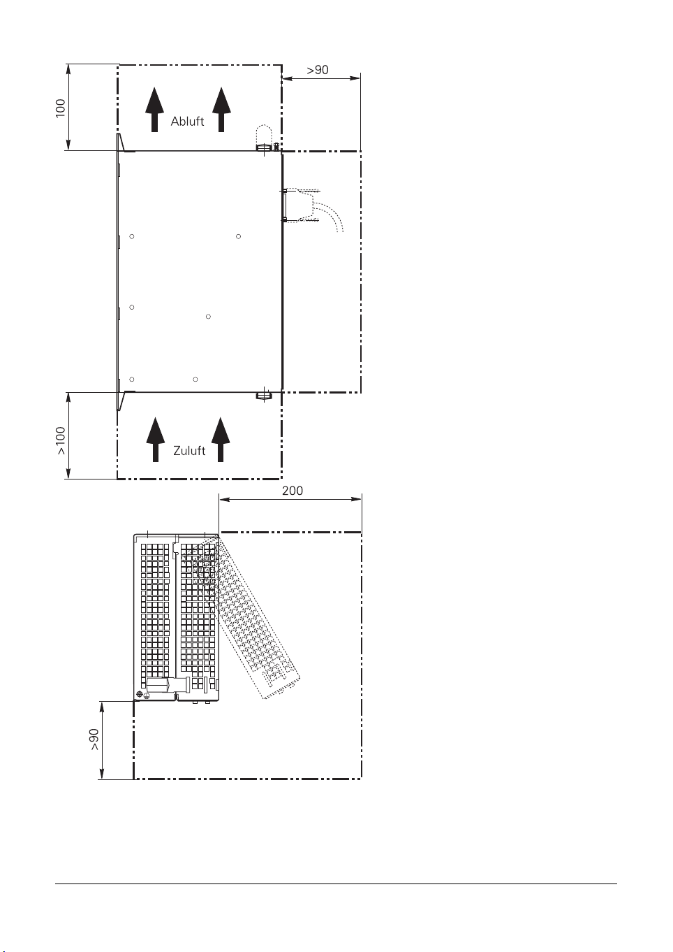
Mounting Position of LE 370 D
Free space for air
circulation!
Leave space for
servicing
Free space for
air circulation
and servicing
Leave space for
servicing.
Connecting cables must
be laid in a way that allows
the LE to be opened!
Id. Nr.
July 02 Mounting and Electrical Installation TNC 370 D 3–9
Page 13
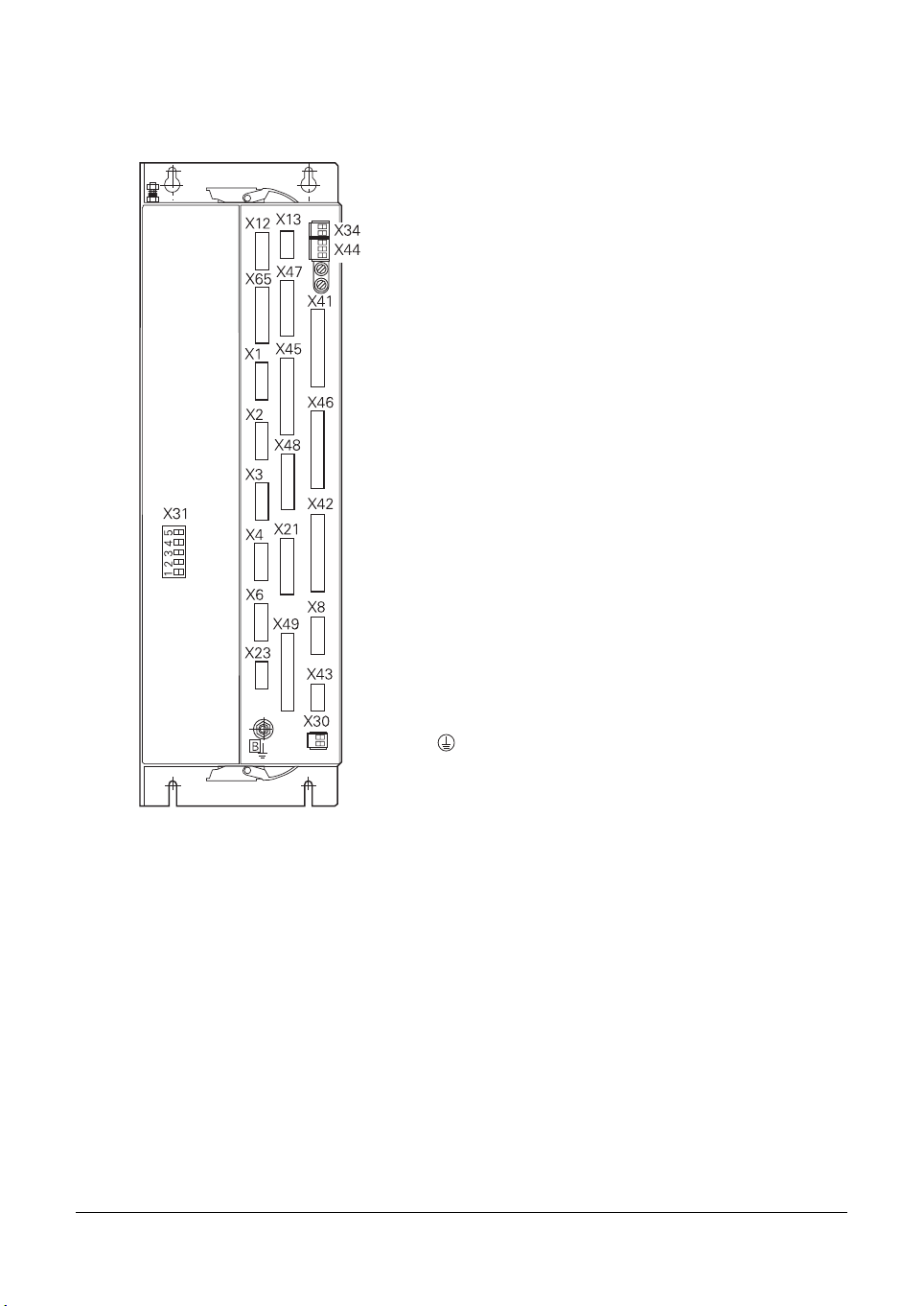
3.7 Connection Overview
3.7.1 LE 370 D
X1
to
X4 Position encoder
X6 Encoder for spindle position
X8 Nominal value output
X12 Triggering touch probe for workpiece
measurement
X13 Triggering touch probe for tool measurement
X21 RS-232-C/V24 data interface
X23 Handwheel input
X30 Reference signal for spindle
X41 PLC output
X42 PLC input
X44 PLC power supply
X43 Flat-panel display BF 370 B
X45 TNC keyboard
X46 Machine operating panel
X47 PLC expansion PL410B/PL405B
X48 PLC analog input
X31 NC power supply
B Signal ground
Protective ground (YL/GN)
3–10 TNC 370 D Mounting and Electrical Installation July 02
Page 14

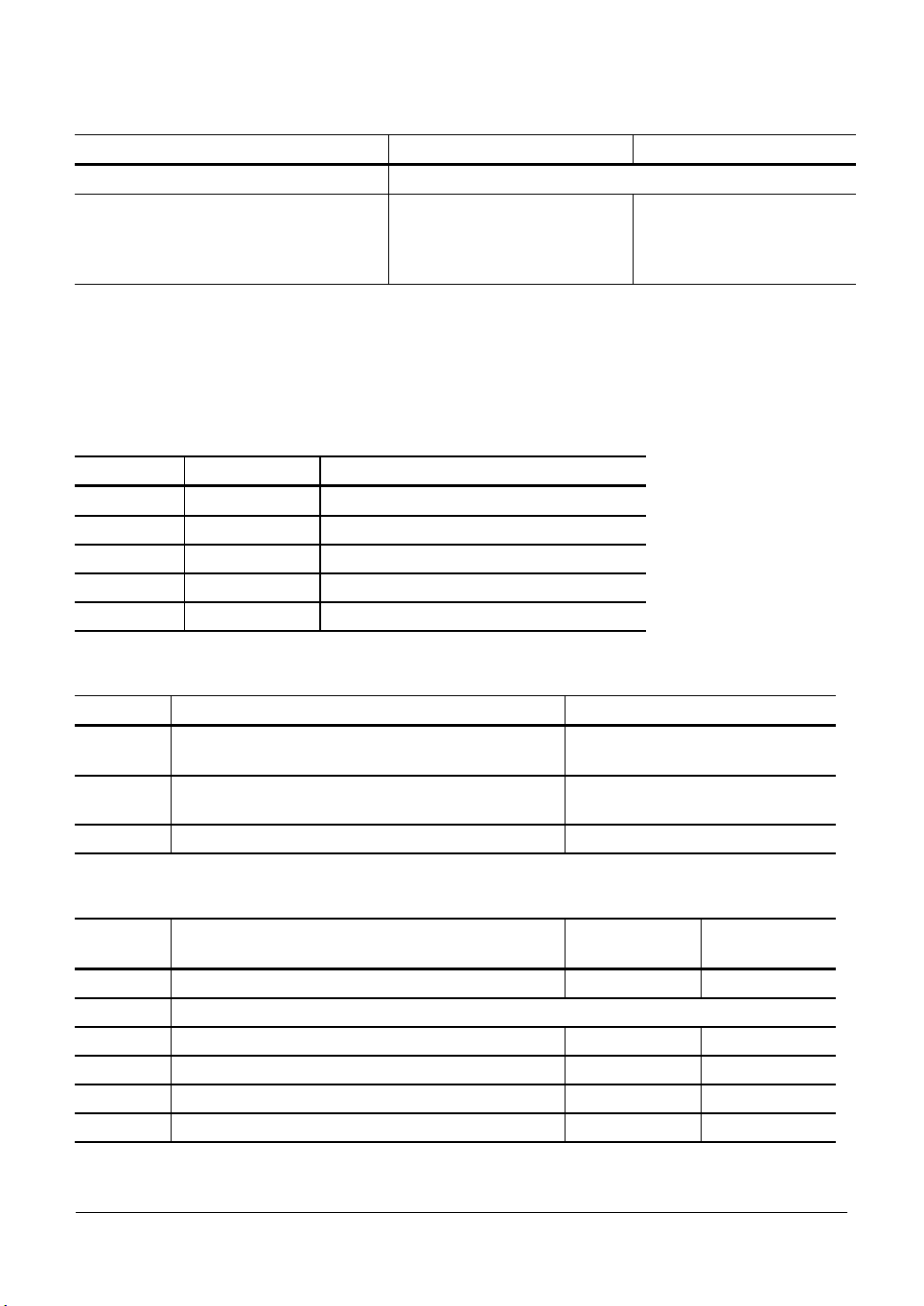
3.7.2 Power Supply
X31 NC Power Supply
Terminal
X31
PE
U1 L1 330 Vac to 450 Vac;
U2 L2
–UZ Do not use
+UZ Do not use
Danger to internal components!
Do not engage or disengage any connections while the unit is under power.
Assignment
Protective ground (YL/GN)
50 to 60 Hz
July 02 Mounting and Electrical Installation TNC 370 D 3–11
Page 15

X44 PLC Power Supply
Terminal Assignment Fuse
1 + 24 Vdc can be switched off via EMERGENCY STOP F 3,15 A
2 + 24 Vdc cannot be switched off via EMERGENCY STOP F 2 A
3 0 V
HEIDENHAIN recommends that you operate the PLC of the LE (and the PL 410B/PL 405B) with a 24 V
control voltage that is generated as per VDE 0551. The control voltage must be smoothed with approx.
150µF / A (at 15 A, this corresponds to a smoothing capacity of 2250 µF), where a minimum capacity of
1000µF (63V) is to be ensured.
2
The 0 V line of the PLC power voltage must be connected by a grounding line (Ƴ 6 mm
) with the
central signal ground of the machine.
Supply
voltage
Voltage range,
mean dc voltage
Max. current consumption
(when half of the outputs
are on simultaneously)
Current
consumption
(when half of the
outputs are on
simultaneously)
24 Vdc
EN 61 1312: 1994;
VDE 0411 Part
500
Lower limit
19,2 V
Upper limit
30 V
- - -
- - -
,
,
LE 370 D: 2 A
LE 370 D: 48 W
Besides the voltage tolerance, a dc component with a peak value of 5% of the rated voltage is
permissible. The absolute limits lie at 30 V/19.2 V.
Danger to internal components!
Use only original replacement fuses.
3–12 TNC 370 D Mounting and Electrical Installation July 02
Page 16

3.7.3 Measuring System Inputs
HEIDENHAIN TNC contouring controls are designed for use with incremental linear and angular
encoders as measuring systems.
However, HEIDENHAIN recommends using encoders with distance-coded reference marks because
they significantly reduce the traverse distance required to establish the absolute position.
Maximum current load per encoder input: 200 mA
Use only original HEIDENHAIN encoder cables, connectors and couplings. For maximum cable
lengths see “Cable Overview.”
Encoder for Position with 1 V
Maximum input frequency: 350 kHz (via MP 115.1 switchable to 50 kHz)
X1, X2, X3, X4 and X6 (Spindle) Encoder (1 V
Logic unit Encoder cable
D-sub
Assignment D-sub
terminal
(male) 15-pin
1 + 5 V (UP) 1 Brown/Green
2 0 V (UN) 2 White/Green
3 A+ 3 Brown
4 A– 4 Green
5 0 V 5
6 B+ 6 Gray
7 B– 7 Pink
8 0 V 8
9 + 5 V 9 Blue
10 R+ 10 Red
11 0 V 11 White
12 R– 12 Black
13 0 V 13
14 Do not use 14 Violet
15 Do not use 15
Housing External shield Housing External shield
For the spindle position, HEIDENHAIN recommends the ROD 486 with 1024 or 2048 lines.
The 1 VPP signals are interpolated by a factor of 1024.
SS
) (via MP 115.0 switchable to 11µA)
PP
connector
(female) 15-pin
July 02 Mounting and Electrical Installation TNC 370 D 3–13
Page 17

3.7.4 Reference Signal for the Spindle
Usually, the reference mark of the spindle encoder is evaluated as a reference signal for the spindle.
In special cases, a 24 V signal on terminal X30 can be evaluated as a reference signal for the spindle
or as a reference signal release (see chapter “Spindle”). For reliable evaluation, the signal must last
for at least 3 milliseconds.
X30 Spindle Reference Signal
Terminal Assignment
1 +24 V input
2 0 V
3.7.5 Supply voltage for Control-is-Ready Signal
The power supply for the control-is-ready signal is taken from the 24 V power supply of the PLC.
X34 power supply for control-is-ready signal
Connecting terminal Assignment
1 +24 V PLC
2 0 V
3–14 TNC 370 D Mounting and Electrical Installation July 02
Page 18

3.7.6 Analog Nominal Value Output
Maximum loading of the analog outputs: 2 mA
Maximum capacitance: 2 nF
X8 Nominal Value Output
Logic unit Connecting Cable
D-sub terminal
(female) 15-pin
1 Nominal value output 1 1 BN
2 Analog input 2 BN/GN
3 Nominal value output 2 3 YL
4 Do not use 4 RD/BL
5 Nominal value output 3 5 PK
6 Do not use 6 GY/PK
7 Nominal value output 4 7 RD
8 Nominal value output 5 8 VI
9 0V Nominal value output 1 9 WH
10 0V Analog input 10 WH/GY
11 0V Nominal value output 2 11 GN
12 Do not use 12
13 0V Nominal value output 3 13 GY
14 0V Nominal value output 4 14 BL
15 0V Nominal value output 5 15 BK
Housing External shield Housing External shield
· The connecting cables to the nominal value outputs must not have more than one intermediate
terminal.
· If it is necessary to branch to physically separate servo inputs, the connection must be
made in a grounded terminal box. Suitable terminal boxes are available from HEIDENHAIN
(Id. Nr. 251 249 01).
· The chassis of the terminal box must be electrically connected with frame of the machine.
· The 0 V connection of the nominal-value-difference inputs must be connected with signal
ground. Required cross section ³ Ø 6 mm².
· Use only original HEIDENHAIN connecting cables and connecting elements.
Assignment D-sub
connector
(male) 15-pin
Color
July 02 Mounting and Electrical Installation TNC 370 D 3–15
Page 19

The following wiring plan is suggested for shielding in the terminal box :
1 2 3 4 5 6 7 8 9 10 11 12 13 14 15 16
Y
X
LE
Z
SERVO
IV
Insulated against housing
•
Leads are provided
with en sleeves.
Cable screens are led onto 0.14 mm
insulated strands via crimp eyelets.
•
S
Insulated against housing
2
Leads are provided with end sleeves
Cable shields are led onto 0.14 mm² insulated
wires via crimp eyelets.
Connection
Assignment
terminal
1 Nominal value output X axis
2 Nominal value output 0 V X axis
3 Nominal value output Y axis
4 Nominal value output 0 V Y axis
5 Nominal value output Z axis
6 Nominal value output 0 V Z axis
7 Nominal value output IV axis
8 Nominal value output 0 V IV axis
9 Not used
10 Not used
11 Nominal value output S axis
12 Nominal value output 0 V S axis
13 Shield connection
14 Shield connection
15 Shield connection
16 Shield connection
3–16 TNC 370 D Mounting and Electrical Installation July 02
Page 20

3.7.7 Switching Inputs 24 Vdc for the PLC
Voltage ranges: Logic unit PL 410 B/PL 405 B
“1” signal: Ui 13 V to 30.2 V
“0” signal: Ui –20 V to 3.2 V
Current ranges:
“1” signal: Ii 3.8 mA to 8.9 mA 2.5 mA to 6 mA
“0” signal: Ii when Ui = 3.2 V 1.0 mA 0.65 mA
Address No. of inputs Device
I0 to I31 31 + control-is-ready signal Logic unit X42 (PLC input)
I128 to I152 25 Logic unit X46 (machine operating panel)
I64 to I127 64 First PLC input/output board PL 410 B
I92 to I255 64 Second PLC input/output board PL 410 B
I64 to I95 32 PL 405 B
July 02 Mounting and Electrical Installation TNC 370 D 3–17
Page 21

X42 PLC Input at the LE
p
p
Logic unit Con. cable Id.-Nr 244 005 .. / Id. Nr. 263 954 ..
D-sub connector
(female) 37-
1 D-sub connection (female) 37-pin 1 Gray/Red
2 I1 2 Brown/Black
3 I2 3 White/Black
4 I3 acknowledge "control-is-ready"; main processor 4 Green/Black
5 I4 5 Brown/Red
6 I5 6 White/Red
7 I6 7 White/Green
8 I7 8 Red/Blue
9 I8 9 Yellow/Red
10 I9 10 Gray/Pink
11 I10 11 Black
12 I11 12 Pink/Brown
13 I12 13 Yellow/Blue
14 I13 14 Green/Blue
15 I14 15 Yellow
16 I15 16 Red
17 I16 17 Gray
18 I17 18 Blue
19 I18 19 Pink
20 I19 20 White/Gray
21 I20 21 Yellow/Gray
22 I21 22 Green/Red
23 I22 23 White/Pink
24 I23 24 Gray/Green
25 I24 25 Yellow/Brown
26 I25 26 Gray/Brown
27 I26 27 Yellow/Black
28 I27 28 White/Yellow
29 I28 29 Gray/Blue
30 I29 30 Pink/Blue
31 I30 31 Pink/Red
32 I31 32 Brown/Blue
33 I32 (do not use) 33 Pink/Green
34 Do not use 34 Brown
35 0 V (PLC) Test output; Do not use 35 Yellow/Pink
36 0 V (PLC) Test output; Do not use 36 Violet
37 0 V (PLC) Test output; Do not use 37 White
Housing External shield Housing External shield
Assignment
in
D-sub connector
(male) 37-
in
3–18 TNC 370 D Mounting and Electrical Installation July 02
Page 22

PLC Input at the PL 410 B/PL 405 B
X3
Connection terminal Assignment Connection terminal Assignment
1st PL 410 B
PL 405 B
1 I64 I192 1 I80 I208
2 I65 I193 2 I81 I209
3 I66 I194 3 I82 I210
4 I67 I195 4 I83 I211
5 I68 I196 5 I84 I212
6 I69 I197 6 I85 I213
7 I70 I198 7 I86 I214
8 I71 I199 8 I87 I215
9 I72 I200 9 I88 I216
10 I73 I201 10 I89 I217
11 I74 I202 11 I90 I218
12 I75 I203 12 I91 I219
13 I76 I204 13 I92 I220
14 I77 I205 14 I93 I221
15 I78 I206 15 I94 I222
16 I79 I207 16 I95 I223
X5
Connection terminal Assignment Connection terminal Assignment
1st PL 410 B 2nd PL 410 B
1 I96 I224 1 I112 I240
2 I97 I225 2 I113 I241
3 I98 I226 3 I114 I242
4 I99 I227 4 I115 I243
5 I100 I228 5 I116 I244
6 I101 I229 6 I117 I245
7 I102 I230 7 I118 I246
8 I103 I231 8 I119 I247
9 I104 I232 9 I120 I248
10 I105 I233 10 I121 I249
11 I106 I234 11 I122 I250
12 I107 I235 12 I123 I251
13 I108 I236 13 I124 I252
14 I109 I237 14 I125 I253
15 I110 I238 15 I126 I254
16 I111 I239 16 I127 I255
2nd PL 410 B
X4
1st PL 410 B
PL 405 B
X6
1st PL 410 B 2nd PL 410 B
2nd PL 410 B
July 02 Mounting and Electrical Installation TNC 370 D 3–19
Page 23
3.7.8 Switching Outputs 24 Vdc for the PLC
Transistor outputs with current limiting
Min. output voltage for “1” signal 3 V below supply voltage
Nominal operating current per output 0.125 A with simultaneity
· Permissible load: resistive load; inductive load only with quenching diode parallel to the
inductance.
· No more than one output may be shorted on the logic unit at any time. Short circuit of one
output does not cause an overload.
· No more than half the PLC outputs may be driven at the same time (simultaneity factor 0.5).
Address No. of outputs Device
O0 to O30 31 Logic unit X41 (PLC output)
O0 to O7 Logic unit X46 (machine operating panel)
O32 to O62 31 First PL 410 B
O64 to O94 31 Second PL 410 B
O48 to O62 15 PL 405 B
X44 Power Supply for the outputs of the LE
Terminal Assignment PLC outputs
1 +24 Vdc can be switched off via EMERGENCY
STOP
2 +24 Vdc cannot be switched off via EMERGENCY
STOP
3 0V
Power Supply for the outputs on the PL 410 B/ PL 405 B
Terminal Assignment 1st PL 410 B
X9 0 V
X10 +24 Vdc power supply for logic and for control-is-ready signal
X11 +24 Vdc power supply for outputs O32 to O39 O64 to O71
X12 +24 Vdc power supply for outputs O40 to O47 O72 to O79
X13 +24 Vdc power supply for outputs O48 to O55 O80 to O87
X14 +24 Vdc power supply for outputs O56 to O62 O88 to O94
For connecting the PL 410 B to the LE, see section 3.9.14.
3–20 TNC 370 D Mounting and Electrical Installation July 02
Logic unit PL 410 B/PL 405 B
1.2 A with simultaneity
factor of 0.5
O0 to O23
O24 to O30
Pl 405 B
factor of 0.5;
2 A with max. current
consumption of 20 A
2nd PL 410 B
Page 24

X41 PLC Outputs on the LE
p
p
Logic unit Connecting cable
Id. Nr 244 005 .. / Id. Nr. 263 954 ..
D-sub terminal
(female) 37-
1 O0 1 Gray/Red
2 O1 2 Brown/Black
3 O2 3 White/Black
4 O3 4 Green/Black
5 O4 5 Brown/Red
6 O5 6 White/Red
7 O6 7 White/Green
8 O7 8 Red/Blue
9 O8 9 Yellow/Red
10 O9 10 Gray/Pink
11 O10 11 Black
12 O11 12 Pink/Brown
13 O12 13 Yellow/Blue
14 O13 14 Green/Blue
15 O14 15 Yellow
16 O15 16 Red
17 O16 17 Gray
18 O17 18 Blue
19 O18 19 Pink
20 O19 20 White/Gray
21 O20 21 Yellow/Gray
22 O21 22 Green/Red
23 O22 23 White/Pink
24 O23 24 Gray/Green
25 O24 25 Yellow/Brown
26 O25 26 Gray/Brown
27 O26 27 Yellow/Black
28 O27 28 White/Yellow
29 O28 29 Gray/Blue
30 O29 30 Pink/Blue
31 O30 31 Pink/Red
32 Do not use 32 Brown/Blue
33 Do not use 33 Pink/Green
34 Control-is-ready signal 34 Brown
35 24 V (PLC) test output; Do not use 35 Yellow/Pink
36 24 V (PLC) test output; Do not use 36 Violet
37 24 V (PLC) test output; Do not use 37 White
Housing External shield Housing External shield
Assignment D-sub connector
in
(male) 37-
in
July 02 Mounting and Electrical Installation TNC 370 D 3–21
Page 25

PLC Outputs on the PL 410 B/PL405 B
X7
Connection terminal Assignment Connection terminal Assignment
1st PL 410 B 2nd PL 410 B
1 O32 O64
2 O33 O65 2 O49 O81
3 O34 O66 3 O50 O82
4 O35 O67 4 O51 O83
5 O36 O68 5 O52 O84
6 O37 O69 6 O53 O85
7 O38 O70 7 O54 O86
8 O39 O71 8 O55 O87
9 O40 O72 9 O56 O88
10 O41 O73 10 O57 O89
11 O42 O74 11 O58 O90
12 O43 O75 12 O59 O91
13 O44 O76 13 O60 O92
14 O45 O77 14 O61 O93
15 O46 O78 15 O62 O94
16 O47 O79 16 Control-is-ready signal
X8
1st PL 410 B
PL 405 B
1 O48 O80
2nd PL 410 B
3–22 TNC 370 D Mounting and Electrical Installation July 02
Page 26

3.7.9 Machine Operating Panel
Logic unit Connecting cable Id. Nr. 263 954 .. TE 370
D-sub terminal
(female) 37-pin
1 I128 1 Gray/Red 1 1 Coolant ON
2 I129 2 Brown/Black 2 2 Coolant OFF
3 I130 3 White/Black 3 3 Spindle OFF
4 I131 4 Green/Black 4 4 NC STOP
5 I132 5 Brown/Red 5 5 NC START
6 I133 6 White/Red 6 6 X7 I134 7 White/Green 7 7 Y8 I135 8 Red/Blue 8 8 Z9 I136 9 Yellow/Red 9 9 Z+
10 I137 10 Gray/Pink 10 10 Y+
11 I138 11 Black 11 11 X+
12 I139 12 Pink/Brown 12 12 4+
13 I140 13 Yellow/Blue 13 13 414 I141 14 Green/Blue 14 14 Rapid traverse
15 I142 15 Yellow 15 15 Spindle ON
16 I143 16 Red 16 16 17 I144 17 Gray 17 17 18 I145 18 Blue 18 18 19 I146 19 Pink 19 19 20 I147 20 White/Gray 20 20 KEY F5
21 I148 21 Yellow/Gray 21 21 KEY F1
22 I149 22 Green/Red 22 22 KEY F2
23 I150 23 White/Pink 23 23 KEY F3
24 I151 24 Gray/Green 24 24 KEY F4
25 I152 25 Yellow/Brown 25 25 26 O0 26 Gray/Brown 26 26
27 O1 27 Yellow/Black 27 27
28 O2 28 White/Yellow 28 28
29 O3 29 Gray/Blue 29 29
30 O4 30 Pink/Blue 30 30
31 O5 31 Pink/Red 31 31
32 O6 32 Brown/Blue 32 32
33 O7 33 Pink/Green 33 33
34 0 V (PLC) 34 Brown 34 34
35 0 V (PLC) 35 Yellow/Pink 35 35
36 +24 V (PLC) 36 Violet 36 36
37 +24 V (PLC) 37 White 37 37
Housing External
Assignment D-sub
connector
(male) 37-pin
Housing External shield Housing Housing
shield
D-sub connector
(female) 37-pin
X3 D-sub
connector
(female) 37-pin
Key
July 02 Mounting and Electrical Installation TNC 370 D 3–23
Page 27

3.7.10 TNC Keyboard
The TNC keyboard is connected by cable with the logic unit, and by flat cable with the soft keys of
the visual display unit. The flat cable is included with the visual display unit.
X1 on the TNC Keyboard for Connecting the Soft Keys of the Visual Display Unit
Connecting element
(male) 9-pin
1 SL0
2 SL1
3 SL2
4 SL3
5 Do not use
6 RL15
7 RL14
8 RL13
9 RL12
Assignment
3–24 TNC 370 D Mounting and Electrical Installation July 02
Page 28

X45 TNC Keyboard (TE 370)
p
Logic unit Connecting cable Id. Nr. 263 954 .. TE 420
D-sub terminal
(female) 37-pin
1 RL0 1 Gray/Red 1 1
2 RL1 2 Brown/Black 2 2
3 RL2 3 White/Black 3 3
4 RL3 4 Green/Black 4 4
5 RL4 5 Brown/Red 5 5
6 RL5 6 White/Red 6 6
7 RL6 7 White/Green 7 7
8 RL7 8 Red/Blue 8 8
9 RL8 9 Yellow/Red 9 9
10 RL9 10 Gray/Pink 10 10
11 RL10 11 Black 11 11
12 RL11 12 Pink/Brown 12 12
13 RL12 13 Yellow/Blue 13 13
14 RL13 14 Green/Blue 14 14
15 RL14 15 Yellow 15 15
16 RL15 16 Red 16 16
17 RL16 17 Gray 17 17
18 RL17 18 Blue 18 18
19 RL18 19 Pink 19 19
20 SL0 20 White/Gray 20 20
21 SL1 21 Yellow/Gray 21 21
22 SL2 22 Green/Red 22 22
23 SL3 23 White/Pink 23 23
24 SL4 24 Gray/Green 24 24
25 SL5 25 Yellow/Brown 25 25
26 SL6 26 Gray/Brown 26 26
27 SL7 27 Yellow/Black 27 27
28 RL19 28 White/Yellow 28 28
29 RL20 29 Gray/Blue 29 29
30 Not used 30 Pink/Blue 30 30
31 RL21 31 Pink/Red 31 31
32 RL22 32 Brown/Blue 32 32
33 RL23 33 Pink/Green 33 33
34 Spindle override (wiper) 34 Brown 34 34
35 Feed rate override (wiper) 35 Yellow/Pink 35 35
36 +5 V override potentiometer 36 Violet 36 36
37 0 V override potentiometer 37 White 37 37
Assignment D-sub
connector
(male) 37-
D-sub connector
(female) 37-pin
in
X2 D-sub terminal
(male) 37-pin
July 02 Mounting and Electrical Installation TNC 370 D 3–25
Page 29

Housing External shield Housing External shield Housing Housing
3.7.11 Visual Display Unit
X43 Visual Display Unit (BF 370 B)
Logic Unit
Id. Nr. xxx xxx 3x
D-sub terminal
(female) 15-pin
3-row
1 - 1 1 1
2 - 2 2 2
3 Do not use 3 3 3
4 - 4 4 4
5 Do not use 5 5 5
6 Do not use 6 6 6
7 video 7 red 7 7
8 - 8 8 8
9 VSYNC 9 Yellow 9 9
10 - 10 Pink 10 10
11 0V signal 11 Black 11 11
12 - 12 12 12
13 - 13 13 13
14 HSYNC 14 green 14 14
15 clock 15 blue 15 15
Housing External shield Housing External shield Housing Housing
Assignment D-sub
connector
(male) 15-pin
3-row
The interface complies with the recommendations in IEC 742 EN 50 178 for separation
from line power.
Connecting Cable
VB Id.-Nr. 311 535 ..
VL Id.-Nr. 311 536 ..
D-sub connector
(female) 15-pin
3-row
BF 370 B
X2 D-sub terminal
(male) 15-pin
3-row
3–26 TNC 370 D Mounting and Electrical Installation July 02
Page 30

3.7.12 PLC input/output unit PL 410 B/ PL 405 B
Up to two PL 410 B and one PL 405 B can be connected to the LE 370 D.
X47 PL 410 B/PL 405 B input/output unit on the LE
Logic unit Connecting cable Id. Nr. 289 111 .. 1st PL 410 B
X47 D-sub
terminal
(male)
25-pin
1 0 V 1 Brown, Yellow, Pink, Red,
2 0 V 2 Red/Blue, Brown/Green,
3 0 V 3 Brown/Blue, Brown/Red,
4 Do not use 4 Gray/Green 4 4 Serial IN 2
5
6 INTERRUPT 6 Pink/Green 6 6 INTERRUPT
7
8
9 WRITE EXTERNAL 9 White/Red 9 9 WRITE EXTERNAL
10
11
12
13 Do not use 13 13 13 Do not use
14 PCB identifier 4 14 Yellow/Blue, Pink/Blue,
15 PCB identifier 3 15 Yellow/Red, Gray/Red,
16 Do not use 16 Gray/Blue 16 16 PCB identifier 2
17 Do not use 17 Green/Black 17 17 PCB identifier 1
18
19 Serial IN 1 19 White/Black 19 19 Serial IN 1
20 EMERGENCY STOP 20 Green/Red 20 20 EMERGENCY STOP
21
22 Serial OUT 22 White/Pink 22 22 Serial OUT
23
24
25
Housing External shield Housing External shield Housing Housing External shield
July 02 Mounting and Electrical Installation TNC 370 D 3–27
Assignment D-sub
connector
(female)
25-pin
Address 6
RESET
WRITE EXTERNAL
Address 5
Address 3
Address 1
Address 7
Serial OUT
Address 4
Address 2
Address 0
5 White/Green 5 5
7 Green/Blue 7 7
8 White/Blue 8 8
10 Gray/Pink 10 10
11 Blue 11 11
12 Green 12 12
18 White/Yellow 18 18
21 White/Gray 21 21
23 Black 23 23
24 Gray 24 24
25 White 25 25
D-sub
Violet
Yellow/Brown, Gray/Brown,
Pink/Brown
Brown /Black, Yellow/Gray,
Yellow/Pink
Yellow/Black
Pink/Red
X1 D-sub
connector
(male)
25-pin
1 1 0 V
2 2 0 V
3 3 0 V
14 14 + 12 V
15 15 + 12 V
terminal
(female)
25-pin
Assignment
Address 6
RESET
WRITE EXTERNAL
Address 5
Address 3
Address 1
Address 7
Serial OUT
Address 4
Address 2
Address 0
Page 31

3.7.13 Touch Trigger Probes
Any of the following touch trigger probes for workpiece measurement can be connected.
TS 220 Touch trigger probe with cable connection: for digitizing, workpiece setup and
workpiece measurement during machining
TS 630 Touch trigger probe with infrared transmission: for workpiece setup and workpiece
measurement during machining
X12 Touch Probe Input for Workpiece Measurement
Logic unit
D-sub terminal
(female) 15-pin
1 0 V
3 Ready
4 Start
5 +15 V ± 10% (maximum 100mA)
6 + 5 V ± 5% (maximum 100mA)
7
8 0 V (UN)
9 Trigger signal
10
2, 11 to 15 Do not use
Housing External shield
1) Stylus at rest means logic level High
Assignment
Battery warning
Trigger signal
1
3–28 TNC 370 D Mounting and Electrical Installation July 02
Page 32

Adapter cable Id. Nr.274 543 TS120 Id. Nr. 265 348 ..
TS220 Id. Nr. 293 488 ..
D-sub
connector
(male) 15-pin
3 Pink 4 4 Gray
5 Gray
6 Brown/Green 2 2 Brown
7 Gray 3 3 Gray
8 White/Green 1 1 White
9 Green 5 5 Green
10 Yellow 6 6 Yellow
Housing External shield Housing Housing External shield
Connecting cable Id. Nr. 310 197 .. EA Id. Nr. 262 904 01
D-sub
connector
(male) 15-pin
1 White/Brown
3 Gray 5 5 Gray
4 Yellow 3 3
5 Brown 2 2 Brown
7 Blue 6 6 Blue
8 White 1 1 White
10 Green 4 4 Green
Housing External shield Housing Housing External
Coupling on
mounting base
6-pin
Connector
(female)
7-pin
7 7 Internal
internal shield
Quick
disconnect
6-pin
Coupling on
mounting
base 7-pin
TS 630
shield
shield
Id. Nr.
293 714 ..
July 02 Mounting and Electrical Installation TNC 370 D 3–29
Page 33

TT 130 Triggering Touch Probe for Workpiece Measurement
X13 Touch Probe Input for Workpiece Measurement
Logic unit
D-sub terminal
Assignment
(female) 9-pin
1 Ready
2 0 V (UN)
4 +15 V ± 5% (UP)
7 +5 V ± 5% (UP)
8 Trigger signal
9
Trigger signal
1
3, 5, 6 Do not use
Housing External shield
1 Stylus at rest means logic level High
Adapter cable Id. Nr. 335 332 .. TT 130 Id. Nr. 296 537 06
D-sub
connector
(male) 9-pin
Coupling on
mounting base
Connector
(male) 6-pin
(female) 6-pin
1 Pink 6 6
2 White/Green 1 1 White
4 Gray 5 5
7 Brown/Green 2 2 Brown
8 Green 3 3 Green
9 Yellow 4 4 Yellow
Housing External shield Housing Housing External shield
3–30 TNC 370 D Mounting and Electrical Installation July 02
Page 34

3.7.14 RS-232-C/V.24 Data Interface
· Maximum cable length 20 meters
· To connect a peripheral device you must install an adapter cable either in the switching cabinet
or on the operating panel. See also the “Dimensions” section in the Appendix.
· For information on interface cables, see “Cable Overview.”
Logic unit Connecting cable
Id. Nr. 239 760 ..
D-sub
termina
l
(female)
25-pin
1 GND 1 WH/BN
2 RxD 2 Green 3 3 3 3 Yellow 2
3 TxD 3 Yellow 2 2 2 2 Green 3
4 CTS 4 Gray 5 5 5 5 Pink 4
5 RTS 5 Pink 4 4 4 4 Gray 5
6 DTR 6 Blue 20 20 20 20 Brown 6
7 Signal GND 7 Red 7 7 7 7 Red 7
20 DSR 20 Brown 6 6 6 6 Blue 20
8 to 19,
21 to 25
Housing External
Assignment D-sub
connector
(male)
25-pin
Do not use 8 8 8 8 8
Housing External
shield
D-sub
connector
(female)
25-pin
1 1 1 1 WH/BN
External
shield
Housing Housing Housing Housing External
shield
The interface complies with the recommendations in IEC 742 EN 50 178 for separation
from line power.
Adapter block
Id. Nr. 239 758 01
D-sub
terminal
(male)
25-pin
D-sub
terminal
(female)
25-pin
D-sub
connector
(male)
25-pin
Connecting cable
Id. Nr. 274 545 01
D-sub
connector
(female)
25-pin
1
External
shield
Housing
shield
July 02 Mounting and Electrical Installation TNC 370 D 3–31
Page 35

3.7.15 Handwheel Input
Any of the following handwheels can be used with the LE 370 D:
One HR 410 portable handwheel
One HR 130 panel-mounted handwheel or
One HRA 110 handwheel adapter for connecting three HR 150 panel-mounted handwheels
X23 Handwheel Input
D-sub terminal
(female) 9-pin
2 0 V
4 +12 V ± 0.6 V (Uv)
6 DTR
7 TxD
8 RxD
9 DSR
1, 3, 5 Not used
Housing External shield
The interface complies with the recommendations in IEC 742 EN 50 178 for separation
from line power.
Assignment
3–32 TNC 370 D Mounting and Electrical Installation July 02
Page 36

HR 410 Portable Handwheel
The HR 410 is a portable electronic handwheel with:
· Five axis-selection keys
· Two traverse direction keys
· Three keys with predefined traverse speeds (slow, medium, fast)
· Actual-position-capture key
· Three keys for machine functions to be determined by the machine tool builder
· Two permissive keys
· EMERGENCY STOP button
· Holding magnets
Dummy plug for EMERGENCY STOP circuit (option) Id. Nr. 271 958 03
Connecting cable (spiral cable) Id. Nr. 312 879 01
Connecting cable (normal cable) Id. Nr. 296 467 ..
Connecting cable (with metal armor) Id. Nr. 296 687 ..
Extension cable
Id. Nr. 281 429..
D-sub
connector
(male)
9-pin
Housing Shield Housing Housing Shield Housing Housing Shield Housing Housing Shield
2 White 2 2 White E E White E E
4 Brown 4 4 Brown D D Brown D D
6 Yellow 6 6 Yellow B B Yellow B B
7 Gray 7 7 Gray A A Gray A A
8 Green 8 8 Green C C Green C C
6 6 WH/BK 6 6
7 7 YL/BK 7 7
5 5 WH/RD 5 5
4 4 WH/BL 4 4
2 2 WH/GN 2 2
3 3 WH/YL 3 3
1 1 WH/BN 1 1
D-sub
connector
(female)
9-pin
D-sub
connector
(male)
9-pin
Adapter cable
Id. Nr. 296 466..
Coupling
on mounting base
(female)
18-pin
Connecting cable
Id. Nr. 296 467 05
Connector
(male)
18-pin
Connec-
tor
(female)
18-pin
HR 410
Id. Nr. 296 469 01
Connector
(male)
18-pin
WH/BN 3 Contact 1 + 2
WH/YL 2 Contact 2 (left) Permissive button
WH/GN 1 Contact 1 (right)
WH/BL 1 Contact 1
WH/RD 2 Contact 1 EMERGENCY STOP
YL/BK 3 Contact 2
WH/BK 4 Contact 2
The adapter includes plug-in terminal strips for the contacts of the EMERGENCY STOP button and
permissive button (maximum load 1.2 A, 24 V).
July 02 Mounting and Electrical Installation TNC 370 D 3–33
Page 37

Internal wiring of contacts to permissive buttons and EMERGENCY STOP button of the HR 410:
Right Left
The plug-in terminal strips are included in delivery with the adapter cable. If you have an immediate
need for these terminal strips before the adapter cable, they can be ordered separately:
Plug-in terminal strip, 3-pin Id. Nr. 266 364 06
Plug-in terminal strip, 4-pin Id. Nr. 266 364 12
HR 130 Panel-Mounted Handwheel
The HR 130 is the panel-mount version of the HR 330 without axis keys, rapid traverse keys, etc. It
is connected to the logic unit directly or by extension cable.
The HR 130 is available in various versions (standard cable length 1 meter):
· Small knob, axial cable outlet: Id. Nr. 254 040 01
· Small knob, radial cable outlet: Id. Nr. 254 040 02
· Large knob, axial cable outlet: Id. Nr. 254 040 03
· Large knob, radial cable outlet: Id. Nr. 254 040 04
· Ergonomic knob, radial cable outlet: Id. Nr. 254 040 05
(See also the "Dimensions" section in the Appendix)
Extension cable Id. Nr. 281 429 .. HR 130 Id. Nr. 254 040 ..
D-sub connector
(male) 9-pin
Housing Shield Housing Housing Shield
2 White 2 2 White
4 Brown 4 4 Brown
6 Yellow 6 6 Yellow
8 Green 8 8 Green
7 Gray 7
D-sub connector
(female) 9-pin
D-sub connector
(male) 9-pin
3–34 TNC 370 D Mounting and Electrical Installation July 02
Page 38

HRA 110 Handwheel Adapter
The HRA 110 handwheel adapter enables you to connect two or three HR 150 panel-mounted
handwheels to the TNC. The first and second handwheels are permanently assigned to the X and Y
axes. The third handwheel can be assigned to the X, Y, Z or IVth axis, either by a step switch
(option) or with MP7645 (see “Machine Integration”).
HR 150
HRA 110
X31 24 V
X23
S2
S1
Achswahl (Option)
AXIS SELECTION (OPTIONAL)
Unterteilungsfaktorwahl (Option)
INTERPOLATION FACTOR (OPTIONAL)
X23
Id.-Nr. 270 909..
max. 50 m
X1
X2
X3
max. 20 m
An additional step switch (option) provides such functions as the selection of the handwheel
interpolation factors. You must evaluate the current setting of the step switch in the PLC and then
activate the corresponding interpolation factor with Module 9036.
X1, X2, X3 Handwheel Inputs for HR 150
HRA 110
Terminal (female)
Assignment
9-pin
1 I1+
2 I1–
5 I2+
6 I2–
7 I0+
8 I0–
3 + 5 V
4 0 V
9 Internal shield
Housing External shield
July 02 Mounting and Electrical Installation TNC 370 D 3–35
Page 39

X23 Connection to Logic Unit
HRA 110
D-sub terminal
(male) 9-pin
1 RTS
2 0 V
3 CTS
4 +12V + 0.6 V (Uv)
5 Do not use
6 DSR
7 RxD,
8 TxD,
9 DTR
Housing External shield
X31 Power Supply
Terminal Assignment
1 + 24 Vdc
2 0 V
Power supply: 24 Vdc VDE 0160, basic insulation
Max. current consumption: 200 mA
Assignment
HRA 110
3–36 TNC 370 D Mounting and Electrical Installation July 02
Page 40

3.7.16 Analog Inputs
The logic unit and the PL 410 B input/output board can be supplied with analog inputs (± 10 V) and
inputs for connecting Pt 100 thermistors .
Analog inputs (± 10 V) Inputs for Pt 100
thermistors
LE 370 D 3 on connector X48 2 on connector X48
PL 410 B (Id. Nr. 263 217 02) 4 4
The current values of these inputs are interrogated with Module 9003.
Analog inputs: Voltage range -10 V to +10 V
Input resistance > 250 kW
Resolution 100 mV
Internal value range –100 to +100
Inputs for Pt 100 thermistors:
Constant current 5 mA
Temperature range 0° C to 100° C
Resolution 0.5° C
Internal value range 0 to 200
July 02 Mounting and Electrical Installation TNC 370 D 3–37
Page 41

X48 Analog Input (PLC) at the LE
D-sub terminal
Assignment
(female) 25-pin
1 I1+ Constant current for Pt 100
2 I1– Constant current for Pt 100
3 U1+ Measuring input for Pt 100
4 U1– Measuring input for Pt 100
5 I2+ Constant current for Pt 100
6 I2– Constant current for Pt 100
7 U2+ Measuring input for Pt 100
8 U2– Measuring input for Pt 100
9 Do not use
10 Do not use
11 Do not use
12 Do not use
13 Do not use
14 Analog input 1 –10 V to +10 V
15 Analog input 1 0 V (reference potential)
16 Analog input 2 –10 V to +10 V
17 Analog input 2 0 V (reference potential)
18 Analog input 3 –10 V to +10 V
19 Analog input 3 0 V (reference potential)
20 to 25 Do not use
Housing External shield
The correct polarity of analog inputs is essential.
X15, X16, X17, X18 Analog inputs on the PL 410 B
Terminal Assignment
1 –10 V to +10 V
2 0 V (reference potential)
3 Shield
3–38 TNC 370 D Mounting and Electrical Installation July 02
Page 42

X23 Power supply at the analog inputs
Terminal Assignment
1 +24 Vdc (IEC 742 EN 50 178, 5.88 low-voltage electrical separation)
2 0 V
X19,X20,X21,X22 Connection for Pt 100 on the PL 410 B
Terminal Assignment
1 I + Constant current for Pt 100
2 U + Measuring input for Pt 100
3 U – Measuring input for Pt 100
4 I – Constant current for Pt 100
5 Shield
Connection to the analog inputs
Connecting cable 2 x 0.14 mm
Connection to the inputs for Pt 100 thermistors
The connection to the Pt 100 thermistors must be arranged as a four-wire circuit.
e.g. PL 410 B X19:
2
shielded, max. 50 m.
I+
→
Measuring input U+
Measuring input U–
I–
→
1
2
3
4
5
Pt100 Customer´s cable
4 x 0.14 mm2 screened, max 50 m
July 02 Mounting and Electrical Installation TNC 370 D 3–39
Page 43

3.8 Visual Display Unit BF 370 B
The BF 370 B visual display unit consists of a flat-panel display, soft keys and numeric keypad (see
dimension drawing).
The following connections are available on the BF 370 B:
Connector on BFT 110 Function Connector on LE 310 M
X1 Operating voltage for screen 24 Vdc
(PLC)
X2 Screen X43 (see Chapter 1.10.9)
X2 supply voltage for screen
Connecting terminal Assignment
1 + 24 V (power consumption 15 W; supply voltage with basic insulation
as per EN 50 178
2 0V
-
3–40 TNC 370 D Mounting and Electrical Installation July 02
Page 44

3.9 Mounting Dimensions
LE 370 D
July 02 Mounting and Electrical Installation TNC 370 D 3–41
Page 45

p
BF 370 B
F = Front panel opening
---=Free s
ace for air circulation
3–42 TNC 370 D Mounting and Electrical Installation July 02
Page 46

TE 370
17–0.5
.67"–.02"
366+1
14.41"+.04"
R 60
174
R2.36"
6.85"
.2"–.02"
0.2
±
388
.008"
±
15.276"
5–0.5
0.5
.02"
30
1.18"
X3
X1X2
5
M
N
IO
T
5
C
E
M
N
ß
N
lu
O
C
sch
D
N
U
O
assean
R
M
G
CE
A
RF
SU
G
TIN
ontagefläche
N
M
U
O
M
9.92"+.04"
252+1
G
IN
PEN
EL O
N
A
T P
N
Frontplattenausschnitt
FRO
380+1
14.97"+.04"
400
15.75"
0.2
±
388
.008"
±
15.276"
.51"–.02"
13–0.5
Ø 5.5
DIA.217"
9.8"+.04"
249+1
5
M
.008"
±
0.2
10.315"
±
262
2.36"
60
4–0.5
1.26"
32
.16"–.02"
0.2
±
6
.088"
±
.236"
.008"
±
0.2
.008"
±
10.305"
±
262
10.79"
274
0.2
.236"
±
6
45
1.77"
25
.98"
July 02 Mounting and Electrical Installation TNC 370 D 3–43
Page 47

3.10 Cable overview
HR 410
296 469-01
23.07.96
50m
Accessories
3m
HR 130
254 040-xx
HR 150
257 061-xx
max. 20 m
20m
50m
PC
TT 130
50m
TS 630
30m
296 537-06
TS 220
293 488-xx
TS 230
293 491-xx
EA 550
262 904-01
293 714-xx
VL: Extension cable
for separation points with connecting cable
for extending existing connecting cable
296 466-xx
289 111-xx
PL 410 B
263 371-12
PL 405 B
263 371-22
289 111-xx
TE 370
288 713-02
BF 370 B
288 708-04
263 954-xx
311 535-xx
286 998-xx
4 inputs
274 545-01
RS-232-C Adapter
D
LE 370
1 input
310 085-01
VL
263 955-xx
263 954-xx
335 332-xx
244 005-xx
Machine
25m
operating
TS 220 274 543-xx
TS 230 335 331-xx
37-pin male connector
243 937-ZY
panel
15-pin male connector
243 971-ZY
25m
Terminal box
244 005-xx
290 109-xx
251 249-01
310 197-xx
263 954-xx
290 110-xx
PLC I / 0
Nominal value
output
20m
312 879-01
50m
VL
281 429-xx
VL
263 955-xx
VL
311 536-xx
HRA 110
270 909-xx
3 inputs
261 097-01
310 199-xx
25m
TNC 370 D
309 783-xx
310 199-xx
298 429-xx
298 430-xx
PP
1 V
9m
Encoders for
position control
60m
PP
1 V
309 783-xx
PP
1 V
60m
Rotary encoder
for spindle orientation
3–44 TNC 370 D Mounting and Electrical Installation July 02
Page 48

3.11 Grounding plan
July 02 Mounting and Electrical Installation TNC 370 D 3–45
Page 49

3–46 TNC 370 D Mounting and Electrical Installation July 02
Page 50

4 Machine Parameters
4.1 What Is a Machine Parameter?
A contouring control must have access to specific data (e.g., traverse distances, acceleration) before
it can execute its programmed instructions. You define these data in so-called machine parameters.
In addition, machine parameters can be used to activated certain functions, which are
possible with HEIDENHAIN contouring controls, but are required only on certain types of machines
(e.g. automatic tool changing). The list of machine parameters is not numbered in sequence but is
divided into groups according to function.
Machine parameter Functional Group
10 to 999 Encoders and Machines
1000 to 1399 Positioning
1400 to 1699 Operation with Velocity Feedforward
1700 to 1999 Operation with Servo Lag
2000 to 2999 Integrated Closed-Loop Speed and Current Control
3000 to 3999 Spindle
4000 to 4999 Integral PLC
5000 to 5999 Data Interface
6000 to 6199 3-D Touch Probe
6200 to 6299 Digitizing with Triggering Touch Probe
6500 to 6599 Tool Measurement with Touch Trigger Probe
7100 to 7199 Tapping
7200 to 7349 Display and Operation
7350 to 7399 Colors
7400 to 7599 Machining and Program Run
7600 to 7699 Hardware
If there is more than one input value for a single function (e.g., a separate input for each axis), the
parameter number is provided with indices that are permanently assigned to the corresponding
axes: Index zero is always axis X, index one is always axis Y, etc.
Example:
MP1010.0-3 Rapid traverse
MP1010.0 Rapid traverse for axis X
MP1010.1 Rapid traverse for axis Y
MP1010.2 Rapid traverse for axis Z
MP1010.3 Rapid traverse for axis 4
Other machine parameters function as on/off switches for specific functions. These machine
parameters are bit-coded. Each bit is assigned to either an axis or a function.
July 02 Machine Parameters TNC 370 D 4–47
Page 51

4.2 Input and Output of Machine Parameters
If the machine parameters have not yet been entered in a HEIDENHAIN contouring control (e.g.,
during commissioning), the TNC presents the list of machine parameters after the memory test.
Now you must enter the values either by hand on the keyboard or through the data interface.
4.2.1 Input Format
A number is entered for each machine parameter. This value can be, for example, the acceleration
in mm/s
entry by placing a semicolon ";" behind the numerical entry, followed by your comment. The input
values can be entered in decimal, binary (%) or hexadecimal ($) format.
There are machine parameters with which individual functions are activated bit-coded. Binary
entry (%) is recommended for these machine parameters. The hexadecimal format ($) may be
advisable for other machine parameters.
2
of an individual axis, or the analog voltage in volts. You can add a written comment to your
4.2.2 Activating the Machine Parameter Settings
After you have entered the values for the machine, exit the machine parameter list by pressing the
END key. Missing or incorrect entries result in error messages from the control that prompt you to
correct your entry. The following errors are displayed:
Input error Meaning
0 No MP number found
1 Invalid MP number
2 No separator ";" found
3 Entry value incorrect
4 MP doubly defined
6 MP can not be stored
If the control does not recognize any errors, it automatically exits the machine parameter editor and
is ready for operation. If during commissioning you do not make any entries in the parameter list
(MP NAME), the TNC will generate a standard machine parameter list when you press the END key
and leave the machine parameter editor. In this list the TNC is defined as a programming station
with the HEIDENHAIN standard colors. All other machine parameters assume the minimum value.
You can keep several machine parameter lists and load the desired list into the TNC when
needed. The desired list can be selected in the machine parameter editor by pressing the PGM
MGT key and the SELECT soft key. The parameter list that is active when you exit the machine
parameter editor goes into effect.
4–48 TNC 370 D Machine Parameters July 02
Page 52

4.2.3 Changing the Input Values
After you have created a machine parameter list, it can be changed either through the machine
parameter editor or directly through the PLC.
The list of machine parameters included the following indicators showing how the value can
be changed and how the TNC reacts after the change:
· CN The MP is also accessible through the code number 123
· PLC The MP can be changed through the PLC
· RUN The MP can also be changed while a program is running.
· RESET Changing the MP results in a reset
· REF The axis must be moved over the reference mark again.
Manual input
Call the machine parameter editor through the MOD function "code number":
· Code number 95148
This code number give you access to the complete list of machine parameters.
· Code number 415263 all commissioning functions are activated , access to MP-editor via soft
key MP-EDIT
· Code number 123
This code number gives you access to only some of the machine parameters. These are the
machine parameters that the user is authorized to change (see User's Manual). In the following
list, the machine parameters that can be changed through the code number 123 are indicated by
„CN123.„
To exit the machine parameter editor, press END.
Users parameters
With the USER PARAMETER MOD function you can easily access certain machine parameters
without having to first enter a code number. In MP7330.x you can define up to 16 machine
parameters, and in MP7340.x you define the associated dialog to be shown when the USER
PARAMETER soft key is pressed. See also the chapter „Display and Operation.„
Changing the input values through the PLC
The PLC can also change the machine parameters. You can use the following modules for this
purpose:
· Overwrite machine parameters (Module 9031)
· Read machine parameters (Module 9032)
· Select machine parameter file (Module 9033)
· Load machine parameter partial file (Module 9034)
In the list below, the machine parameters that you can change with modules 9031 or 9034 are
indicated with „PLC„:
July 02 Machine Parameters TNC 370 D 4–49
Page 53

Overwrite Machine Parameter (Module 9031)
With Module 9031 you can overwrite the value of the given machine parameter with a new value.
The input value must be a natural number including all possible decimal places.
Example: MP910.0 = 100.12 [mm]
Decimal places: 1001200 (4 decimal places)
It is always the value in the process memory that is overwritten, the value in the editable machine
parameter list does not change. This means that the old value is valid again after editing and exiting
from the machine parameter list.
Zero must be given as the index for non-indexed machine parameters. If a RESET MP is
overwritten, an error code is sent.
Once the NC program has started the module operates only during the output of M/S/T/Q strobes.
The reply of the strobe must not occur until the end of the Submit-Job!
Depending on the type of machine parameter, the NC is re-initialized.
Call only from a Submit job:
PS B/W/D/K <MP number>
PS B/W/D/K <MP index>
PS B/W/D <MP value>
CM 9031
PL B/W/D <Error code>
0: No error
1: MP does not exist/not modifiable/not modifiable once the program has
started
2: MP value out of range
3: Error when saving (fatal error), contains RESET parameter
4: Call was not from a Submit job
5: Call during running program without strobe
Read Machine Parameter (Module 9032)
With Module 9032 you can read the value of a machine parameter. The value is transferred as a
natural number including all possible decimal places.
It is always the value from the editable machine parameter list that is read, not any value in
the process memory modified by PLC Module 9031. Zero must be given as the index for nonindexed machine parameters.
Call only from a Submit job:
PS B/W/D/K <MP number>
PS B/W/D/K <MP index>
CM 9032
PL B/W/D <MP value> / <Error code>
1: MP number does not exist
2: No separator „:„
3: MP value out of range
4: MP not in file
5: No MP file found
6: Call was not from a Submit job
4–50 TNC 370 D Machine Parameters July 02
Page 54

Select Machine Parameter File (Module 9033)
With Module 9033 you select an editable machine parameter file. The module does not cause a
system reset, but it does reinitialize the NC. The file name is specified in an empty string, since at
the time a new editable machine parameter file is being handled. Once the NC program has started
the module operates only during the output of M/S/T/Q strobes.
Call only from a Submit job:
PS B/W/D/K <String number> 0 to 3
CM 9033 Note: Program execution ends here if a new file is selected.
PL B/W/D <Error code>
0: No error, file was already selected
1: The specified string does not conform to the above conventions.
2: File found not
3: File is faulty
4: Incorrect string was transferred (out of range 0 to 3)
5: The module was not called from a Submit job.
6: The module was called after the NC program started without a strobe
marker being active.
Loading a Machine Parameter Partial File (Module 9034)
With Module 9034 you load the contents of the given machine parameter file into the main
memory. All parameters not contained in this file remained unchanged. The new MP file to be
selected is checked; no faulty files are loaded. The MP file is not loaded if it contains parameters
that require a system reset. The file name is transferred in a string that must contain the complete
file name. Additional characters (including blank characters) are not allowed. If a RESET MP is
overwritten, an error code is sent. If the PLC program is created externally, ensure that lower-case
letters are not used for the file name. Once the NC program has started the module only operates
during the output of M/S/T/Q strobes.
Call only from a Submit job:
PS B/W/D/K <String number > 0 to 3
CM 9034
PL B/W/D <Error code>
0: No error
1: String does not have a valid file name, or the name (including path) is too
long
2: File found not
3: File is faulty / File contains reset parameters
4: Incorrect string number was transferred (out of range 0 to 3)
5: The module was not called from a Submit job.
6: The module was called after the NC program started without a strobe
marker being active.
July 02 Machine Parameters TNC 370 D 4–51
Page 55

4.3 List of Machine Parameters
4.3.1 Encoders and Machine
Machine
parameter
MP10 Active axes
MP20.0 Checking the absolute position of the
MP20.1 Checking the amplitude of the encoder
MP20.2 Checking the edge separation of the
MP21.0 Checking the absolute position of the
MP21.1 Checking the amplitude of the signals on the
MP21.2 Checking the edge separation of the
MP40
4–52 TNC 370 D Machine Parameters July 02
Function and input Change via Reaction
PLC Reset
Input: %00xxxx
Bit 0 to 3 0 = not active
Axis X to 4 1 = active
Bits 4 and 5 reserved, enter 0
PLC
distance-coded reference marks
Input: %00xxxx
Bit 0 to 3 0 = not active
Axis 1 to 4 1 = active
Bits 4 and 5 reserved, enter 0
PLC
signals
Input: %00xxxx
Bit 0 to 3 0 = not active
Axis 1 to 4 1 = active
Bits 4 and 5 reserved, enter 0
PLC
encoder signals
Input: %00xxxx
Bit 0 to 3 0 = not active
Axis 1to 4 1 = active
Bits 4 and 5 reserved, enter 0
PLC
distance-coded reference marks on the
encoder for the spindle position
Input: %x
Bit 0 0 = not active
Spindle 1 = active
PLC
encoder for the spindle position
Input: %x
Bit 0 0 = not active
Spindle 1 = active
PLC
encoder signals for the spindle position
Input: %x
Bit 0 0 = not active
Spindle 1 = active
Display on screen
Input: %00xxxx
Bit 0 to 3 0 = not active
Axis X to 4 1 = active
Bits 4 and 5 reserved, enter 0
Reset
Page 56

Machine
parameter
MP60
MP110.0-3
MP111 Assignment of the position measuring
MP112.0-3 Assignment of the rpm measuring system
MP113 Assignment of the rpm measuring system
Function and input Change via Reaction
PLC-auxiliary axis
Input: %xxxx
Bit 0 to 3 0 = not active
Axis X to 4 1 = active
Assignment of the position measuring
system inputs for the axes
Input: 0 to 6
0 = no position measuring system
1 = position measuring system input X1
2 = position measuring system input X2
3 = position measuring system input X3
4 = position measuring system input X4
6 = position measuring system input X6
system input for the spindle
Input: 0 to 6
0 = no position measuring system
1 = position measuring system input X1
2 = position measuring system input X2
3 = position measuring system input X3
4 = position measuring system input X4
6 = position measuring system input X6
inputs for the axes
Input: 15 to 19
0 = no rpm measuring system input (analog
axis)
15 = rpm measuring system input X15
16 = rpm measuring system input X16
17 = rpm measuring system input X17
18 = rpm measuring system input X18
19 = rpm measuring system input X19
inputs for the spindle
Input: 15 to 19
0 = no rpm measuring system input (analog
axis)
15 = rpm measuring system input X15
16 = rpm measuring system input X16
17 = rpm measuring system input X17
18 = rpm measuring system input X18
19 = rpm measuring system input X19
Reset
Reset
Reset
Reset
Reset
July 02 Machine Parameters TNC 370 D 4–53
Page 57

Machine
Function and input Change via Reaction
parameter
MP115.0 Position encoder inputs 1VPP or 11µA
Input: %xxxxx
PP
0 = 1V
1 = 11µA
MP115.1 Reserved
Input: %00000
MP115.2 Input frequency of position encoders
Input: %xxxxx
0 = 50kHz for 1V
1 = 350kHz for 1V
; 50kHz for 11µA
PP
; 150kHz for 11µA
PP
MP120.0-3 Assignment of the nominal value output
for the axes
Input: 0 = no controlled axis
1 = analog nominal value to X8/1
2 = analog nominal value to X8/2
3 = analog nominal value to X8/3
4 = analog nominal value to X8/4
5 = analog nominal value to X8/5
MP121 Assignment of the nominal value output
for the spindle
Input: 0 = no controlled spindle
1 = analog nominal value to X8/1
2 = analog nominal value to X8/2
3 = analog nominal value to X8/3
4 = analog nominal value to X8/4
5 = analog nominal value to X8/5
MP210 Count direction of the measuring system
signals of the position measuring system
Input: %00xxxx
Bit 0 to 3 0 = not active
Axis X to 4 1 = active
Bits 4 and 5 reserved, enter 0
MP331.0-3 Distance per number of signal periods out of
MP332
Input: 0.001 to 99 999.999
[mm or °]
MP332.0-3 Number of signal periods in the distance
from MP331
Input: 1 to 16 777 215
MP334.0-3 Distance between reference marks for
encoders with distance-coded reference
marks
Input: 0 to 65535 [grating periods]
0=1000 grating periods
(standard setting)
Reset
Reset
Reset
Reset
4–54 TNC 370 D Machine Parameters July 02
Page 58

Machine
Function and input Change via Reaction
parameter
MP410.3 Axis identification for axis 4
Input: 0 = A
1 = B
2 = C
3 = U
4 = V
5 = W
MP420.3 Activation of Hirth coupling for 4th axis
Input: 0 or 1
(the MP can be read by the PLC, currently it
has no other function in the NC)
0 = Hirth coupling not active
1 = Hirth coupling active
MP430.3 Prescribed jog increment for Hirth coupling
(the MP can be read by the PLC, currently it
has no other function in the NC)
Input: 0.000 to 30.000[°]
MP710.0-3 Backlash compensation
Input: –1.000 to +1.000 [mm] or
[°]
MP711.0-3 Height of reversal spikes during rotation
Input: 0 –1.000 to +1.000 [mm]
MP712.0-3 Compensation value per CLP cycle time
Input: 0.000 to +1.000 [mm]
MP720.0-3 Linear axis-error compensation
Input: –1.0000 to +1.0000 [mm/m]
MP 730 Selection of linear or non-linear axis-error
compensation
Input: %xxxx
0 = linear axis-error compensation
1 = non-linear axis-error compensation
Bit 0 to 3 0 = non-active
Axis X to 4 1 = active
MP810.0-3 Display mode for rotary axes and PLC
auxiliary axes
Input: 0.000 to 99 999.999[°]
0 = display ±99 999.999;
Software limit switch active
¹ 0 = modulo value for display;
Software limit switch inactive
MP910.0-3 Positive software limit switch for traverse
range 1; default setting after power-on;
activation via PLC M4575 = 0, M4574 = 0
Input: –30 000.000 to +30 000.000 [mm] or
[°] (Input values are referenced to the
machine datum)
PLC
PLC
RUN
PLC
RUN
PLC
Reset
PLC
PLC
July 02 Machine Parameters TNC 370 D 4–55
Page 59

Machine
parameter
MP911.0-3 Positive software limit switch for traverse
MP912.0-3 Positive software limit switch for traverse
MP920.0-3 Negative software limit switch for traverse
MP921.0-3 Negative software limit switch for traverse
MP922.0-3 Negative software limit switch for traverse
MP950.0-3 Datum for positioning blocks with M92
MP960.0-3 Machine datum
Function and input Change via Reaction
range 2; Activation via PLC M4575 = 0,
M4574 = 1
Input: –30 000.000 to +30 000.000 [mm] or
[°] (Input values are referenced to the
machine datum)
range 3; Activation via PLC: M4575 = 1,
M4574 = 0
Input: –30 000.000 to +30 000.000 [mm] or
[°] (input values referenced to machine
datum)
range 1; Default setting after power-on;
activation via PLC M4575 = 0, M4574 = 0
Input: –30 000.000 to +30 000.000 [mm] or
[°] (input values referenced to the machine
datum)
range 2; Activation via PLC M4575 = 0,
M4574 = 1
Input: –30 000.000 to +30 000.000 [mm] or
[°] (Input values referenced to the machine
datum)
range 3; Activation via PLC: M4575 = 1,
M4574 = 0
Input: –30 000.000 to +30000.000 [mm] or
[°] (Input values referenced to the machine
datum)
Input: –30 000.000 to +30 000.000 [mm] or [°]
Values referenced to the machine datum
Input: –30 000.000 to +30 000.000 [mm]
or [°]
Values referenced to scale reference point
PLC
PLC
PLC
PLC
PLC
PLC
RUN
Reset
4–56 TNC 370 D Machine Parameters July 02
Page 60

4.4 Positioning
Machine
parameter
MP1010.0-3 Rapid traverse
MP1020.0-3 Manual feed rate
MP1030.0-3 Positioning window
MP1040 Polarity of the nominal value voltage for the
MP1050.0-3 Analog voltage for rapid traverse
MP1060.0-3 Acceleration
MP1070.0 Radial acceleration
MP1070.1 Acceleration at contour transition elements
MP1080.0-3 Integral factor
MP1090 Jerk limiting on the contour
MP1097.0-3 Axis-specific jerk limit
MP1099 Filter order for nominal position value filter
MP1110.0-3 Standstill monitoring
MP1140.0-3 Movement monitor on
Function and input Change via Reaction
Input: 80 to 300 000 [mm/min]
Input: 80 to 300 000 [mm/min]
Input: 0. 001 to 2.000 [mm]
positive traverse direction
Input: %xxxx
Bit 0 to 3 0 = not active
Axis X to 4 1 = active
Input: 1.000 to 9.000 [V]
2
Input: 0.001 to 20.000 [m/s
Input: 0.001 to 20.000 [m/s
Input: 0.001 to 20.000 [m/s
]
2
]
2
]
Input: 0 to 65 535
Input: 0 to 1000 [m/s³]
0 = no jerk limiting (MP 1520 active)
1 to 1000 jerk limiting
(active only with M112 and MP7415.1 bit 2)
Input: 1 to 1000 [m/s
3
]
Recommended input value 10 to 50
Input: 0 to 7
0 = no filter
1 to 7 filter order
Recommended input value 1 to 3
Input: 0.001 to 30.000 [mm]
Input: 0.030 to 10.000 [V]
PLC
PLC
PLC
Reset
PLC
PLC
PLC
RUN
PLC
RUN
PLC
RUN
PLC
PLC
RUN
July 02 Machine Parameters TNC 370 D 4–57
Page 61

Machine
parameter
MP1150 Delay time for erasing the nominal velocity
MP1220 Automatic cyclic offset adjustment
MP1320 Direction for traversing the reference marks
MP1330.0-3 Velocity when traversing the reference
MP1331.0-3 Velocity when leaving the reference end
MP1340.0-3 Axis sequence when traversing the
MP1350.0-3 Functional sequence when traversing the
Function and input Change via Reaction
value after an erasable error message
Positioning error <Axis> #
Input: 0.000 to 65.535 [s]
Recommended: 0
Input: 0 to 65 536 [s]
0 = no automatic adjustment
Input: %xxxx
Bit 0 to 3 0 = not active
Axis X to 4 1 = active
marks
Input: 80 to 300 000 [mm/min]
position (only with MP1350=2)
Input: 80 to 500 [mm/min]
reference marks
Input:
0 = No evaluation of the reference mark
1 = Axis X
2 = Axis Y
3 = Axis Z
4 = Axis 4
reference marks
Input:
0 = linear encoder with distance-coded
reference marks (old routine)
1 = linear encoder with one reference mark
2 = special run (linear measurement via
ROD)
3 = linear encoder with distance-coded
reference marks (new routine)
PLC
RUN
PLC
RUN
Reset
PLC
RUN
PLC
RUN
Reset
Reset
4–58 TNC 370 D Machine Parameters July 02
Page 62

4.5 Operation with Velocity Feedforward
Machine
parameter
MP1390 Velocity feedforward control in the
MP1391 Velocity feedforward control in the "Manual"
MP1410.0-3 Position monitoring for velocity feedforward
MP1420.0-3 Position monitoring for operation with
MP1510.0-3
MP1511.0-3 Factor for stiction compensation
MP1512.0-3 Limit to amount of stiction compensation
MP1513.0-3
MP1520 Transient response
Function and input Change via Reaction
"Positioning with MDI,„ "Program run,
single block" and "Program run, full
sequence„ operating modes
Input:0 or 1
0 = velocity feedforward control
1 = control with servo lag
and "Handwheel" operating modes
Input: %xxxx
0 = control with servo lag
1 = velocity feedforward control
Bit 0 to 3 0 = not active
Axis X to 4 1 = active
control (erasable)
Input: 0.001 to 30.000 [mm]
velocity feedforward control (EMERGENCY
STOP)
Input: 0.001 to 30.000 [mm]
k
factor for velocity feedforward
v
Input: 0.100 to 10.000 [Fehler ] !
Input: 0 to 16 777 215
Input: 0 to 16 777 215 [counting steps]
Feed rate limit for stiction compensation
Input: 0 to 300 000 [Fehler!]
Input: 0.100 to 10.000
Reset
Reset
PLC
PLC
PLC
RUN
PLC
RUN
PLC
RUN
PLC
RUN
PLC
July 02 Machine Parameters TNC 370 D 4–59
Page 63

4.6 Operation with Servo Lag
Machine
parameter
MP1710.0-3 Position monitoring for control with servo
MP1720.0-3 Position monitoring for control with servo
MP1810.0-3
MP1820.0-3 Multiplication factor for the kv factor
MP1830.0-3 Characteristic kink
Function and input Change via Reaction
lag (erasable)
Input: 0.000 to 1 000.000 [mm]
Recommended: 1.2 · servo lag
lag (EMERGENCY STOP)
Input: 0.000 to 1 000.000 [mm]
Recommended: 1.4 · servo lag
k
factor for control with servo lag
v
Input: 0.100 to 10.000 [Fehler ] !
Input: 0.001 to 1.000
Input: 0.000 to 100.000 [%]
4.7 Main Spindle
Machine
parameter
MP3010 Output of rotational speed, gear range
MP3020 Speed range for S code output
Function and input Change via Reaction
Input:
0 = no output of spindle speed
1 = coded output of spindle speed, only if
the speed changes
2 = coded output of spindle speed on each
TOOL CALL
3 = analog output of spindle speed, but
gear change signal only if the speed
changes
4 = analog output of spindle speed, but
gear change signal on each TOOL
CALL
5 = analog output of spindle speed, but no
gear change signal
6 = same as input value 3 but with
controlled spindle for orientation
7 = same as input value 4 but with
controlled spindle for orientation
8 = same as input value 5 but with
controlled spindle for orientation
Input: 0 to 99 999
(with analog output of the spindle speed,
enter 1991 here)
PLC
PLC
PLC
PLC
PLC
Reset
PLC
4–60 TNC 370 D Machine Parameters July 02
Page 64

Machine
parameter
MP3030 Axis stops with TOOL CALL
MP3120 Permissibility of zero speed value
MP3130 Polarity of the nominal speed command
MP3140 Counting direction of spindle speed encoder
MP3142 Line count of the position encoder on the
MP3143 Mounting configuration of spindle position
MP3210.0-7 Nominal value voltage at rated speed
Function and input Change via Reaction
Input:
0 = Axis stops with TOOL CALL
1 = Axis does not stop with TOOL CALL
Input: 0:S = 0 permitted
1:S = 0 not permitted
signal for the spindle
Input:
0 = M03 positive; M04 negative
1 = M03 negative; M04 positive
2 = M03 and M04 positive
3 = M03 and M04 negative
signals
Input: 0 = positive count direction with M03
1 = negative count direction with
M03
spindle
Input: 100 to 9 999 [lines]
encoder
Input: 0 to 2
0 = position encoder directly on the spindle
1 = position encoder via transmission
(transmission ratios in MP3450.x and
MP3451.x). X30 Pin 1 = reference
pulse
2 = position encoder via transmission
(transmission ratios in MP3450.x and
MP3451.x).
X30 Pin 1 = reference pulse release
3 = same as 1, but second reference pulse
is evaluated first
With the input values 1 and 2, the
reference traverse must be activated via
Module 9220
Input: 0.000 to 20.000 [V]
PLC
PLC
Reset
Reset
PLC
RUN
PLC
RUN
PLC
RUN
July 02 Machine Parameters TNC 370 D 4–61
Page 65

Machine
parameter
MP3240.1 Minimum nominal value voltage
MP3240.2 Jog voltage for gear changing
MP3310
MP3310.0
MP3310.1
MP3411
MP3411.0-7
MP3412
MP3412.0
MP3412.1
MP3410.2
MP3410.3
MP3415
MP3415.0
MP3415.1
MP3415.2
MP3415.3
MP3420
MP3430
Function and input Change via
Input: 0 to 9.999 [V]
(M4009/M4010)
Input: 0 to 9.999 [V]
Limits for spindle override
Input: 0 to 150 [%]
Upper limit
Lower limit
Ramp gradient of the spindle at M03 and
M04
Input: 0.000 to 1.999 [V/ms]
Gear range: 1 to 8
Multiplier for MP3411.x
Input: 0.000 to 1.999
For M05
For spindle orientation
For tapping
For rigid tapping
Transient response of the spindle
(functions like MP1520)
Input: 0 to 1000 [ms]
for M03, M04 and M05
for spindle orientation
for tapping
for rigid tapping
Positioning window for the spindle
Input: 0 to 360.000 [°]
Deviation of the reference mark from the
desired position (spindle preset)
Input: 0 to 360.000 [°]
PLC
RUN
PLC
RUN
PLC
RUN
PLC
RUN
PLC
RUN
4–62 TNC 370 D Machine Parameters July 02
Page 66

Machine
Function and input Change via Reaction
parameter
MP3440
v factor for spindle orientation
k
Input: 0.1 to 10 [Fehler ]
!
Gear range 1 to 8
MP3440.0-7
MP3450
MP3450.0-7
MP3451
MP3451.0-7
MP3510
MP3510.0-7
MP3515
MP3515.7
Number of revolutions of the spindle
position encoder
Input: 0 to 255
0 = no transmission
Gear range 1 to 8
Number of revolutions of the spindle
Input: 0 to 255
0 = no transmission
Gear range 1 to 8
Rated speed for gear ranges
Input: 0 to 99 999.999 [rpm]
Gear range 1 to 8
Maximum spindle speed
Input: 0 to 99 999.999 [rpm]
Gear range 1 to 8
MP3520.0 Spindle speed activated by marker M4011
Input: 0 to 99 999.999 [rpm]
MP3520.1 Spindle speed for oriented spindle stop
Input: 0 to 99 999.999 [rpm]
PLC
RUN
PLC
RUN
PLC
RUN
PLC
PLC
PLC
RUN
PLC
RUN
July 02 Machine Parameters TNC 370 D 4–63
Page 67

4.8 Integrated PLC
Machine
parameter
MP4010 PLC program out of EPROM or RAM
MP4020 PLC compatibility
MP4060.0-3 Path-dependent lubrication
MP4070 Compensation per PLC cycle for lag-
MP4110.0-47 Time for Timer T0 to T47
MP4120.0-31 Preset value for counter C0 to C31
MP4130
MP4130.0
MP4130.1
MP4130.2
MP4130.3
MP4130.4
MP4130.5
Function and input Change via Reaction
Input: 0 or 1
0 = EPROM
1 = RAM
Input: %xxxxxxx
Bit 0
0 = non-compatible (marker range 4xxx)
1 = compatible (marker range 2xxx)
Bit 1 to 5 reserved
Bit 6
1 = PLC positions in the format
1/10000 mm; oriented spindle stop
triggered by module 9171 or by marker
M4130/D592 in the format 1/10000°
Input: 0 to 99 999.9999 [mm]
tracking error compensation
Input: 0.001 to 0.005 [mm]
Input: 0 to 65 535 [PLC cycles]
Input: 0 to 65 535 [PLC cycles]
Number the fast PLC inputs
Input: 0 to 255 [No. of the PLC input]
Fast PLC input for suppressing the
monitoring functions
No function
Fast PLC input sets M4590
(signal duration > 6 ms)
Fast PLC input sets M4591
(signal duration > 6 ms)
Fast PLC input sets M4592
(signal duration > 6 ms)
Fast PLC input sets M4593
(signal duration > 6 ms)
Reset
Reset
PLC
RUN
PLC
RUN
PLC
RUN
PLC
RUN
4–64 TNC 370 D Machine Parameters July 02
Page 68

Machine
parameter
MP4131
MP4131.0
MP4131.1
MP4131.2
MP4131.3
MP4131.4
MP4131.5
MP4210.0-47 Setting a number in the PLC (D768 to
MP4220.0-3 Setting a number in the PLC (Word range
MP4230.0-31 Setting a number in the PLC (Module
MP4231.0-31 Setting a number in the PLC (Module
MP4310.0-6 Setting a number in the PLC
Function and input Change via Reaction
Criterion for activating the fast PLC input
from MP4130
Input: 0 = Activation at Low level
1 = Activation at High level
Fast PLC input for switching off the
monitoring functions
No function
Fast PLC input for sets M4590
(signal duration > 6 ms)
Fast PLC input sets M4591
(signal duration > 6 ms)
Fast PLC input sets M4592
(signal duration > 6 ms)
Fast PLC input sets M4593
(signal duration > 6 ms)
D956)
Input: –30 000.000 to +30 000.000 [mm]
W960 to W968)
Input: 0 to 65 535
9032)
Input: –99 999.999 to +99 999.999
9032)
Input: –99 999.999 to +99 999.999
(W976 to W988)
Input: 0 to 65 535
$0000 to $FFFF
July 02 Machine Parameters TNC 370 D 4–65
Page 69

4.9 Adaptation of the Data Interfaces
Machine
parameter
MP5020.0-2 Data format EXT1 to EXT3
MP5030.0-2 MP5030.0 Operating mode EXT1
MP5040 Data transfer rate in operating mode EXT3
Function and input Change via Reaction
Input: %xxxxxxxxx
Bit 0 0 = 7 data bits
1 = 8 data bits
Bit 1 0 = BCC any
1 = BCC not control character
Bit 2 Transmission stop through RTS
0 = not active
1 = active
Bit 3 Transmission stop through DC3
0 = not active
1 = active
Bit 4 0 = even parity
1 = odd parity
Bit 5 0 = parity not required
1 = parity required
Bit 6/7 Stop bits Bit 6 Bit 7
1½ stop bits 0 0
2 stop bits 1 0
1 stop bit 0/1 1/1
Bit 8 0= RTS always active
1= RTS only active when data
transfer is started
Bit 9 0= EOT sent after EXT
1= EOT not sent after EXT
MP5030.1 Operating mode EXT2
MP5030.2 Operating mode EXT3 (PLC)
Input:
0 = "standard data transfer"
1 = "blockwise transfer"
(data transfer via PLC)
Input:
0 = 110 baud 6 = 4800 baud
1 = 150 baud 7 = 9600 baud
2 = 300 baud 8 = 19 200 baud
3 = 600 baud 9 = 38 400 baud
4 = 1200 baud 10 = 57 600 baud
5 = 2400 baud 11 = 115 200 baud
CN
PLC
RUN
CN
PLC
RUN
PLC
RUN
4–66 TNC 370 D Machine Parameters July 02
Page 70

4.10 3-D Touch Probe
Machine
parameter
MP6010 Selection of the touch probe
MP6120 Probe feed rate (triggering touch probe)
MP6130 Maximum measuring range
MP6140 Setup clearance above measuring point
MP6150 Rapid traverse in probing cycle (triggering
MP6160 M function for 180° turn of the spindle
MP6210 Number of the oscillations in normal
MP6230 Feed rate in normal direction
MP6240 Maximum stylus deflection
MP6260 Output of M90 for NC blocks with digitized
MP6270 Rounding decimal places
Function and input Change via Reaction
Input:
0 = Touch probe 220
1 = Touch probe 630
Input: 10 to 3000 [mm/min]
Input: 0.001 to 30 000.000 [mm]
Input: 0.001 to 30 000.000 [mm]
touch probe)
Input: 80 to 30 000 [mm/min]
Input: –1 to 88
–1 = Spindle orientation directly through NC
0 = Function inactive
1 to 88 = Number of the M function for
spindle orientation through the PLC
direction per second
Input: 0 to 65.535 [1/s]
Input: 0 to 1000 [mm/min]
Input: 0 to 10.000 [mm]
data
Input:
0 = no output of M90
1 = output of M90 in each NC block
Input:
0 = output in 0.001-mm steps (1 µm)
1 = output in 0.01-mm steps (10 µm)
CN
PLC
CN
PLC
RUN
CN
PLC
RUN
CN
PLC
RUN
CN
PLC
RUN
CN
PLC
RUN
CN
PLC
RUN
CN
PLC
RUN
CN
PLC
RUN
CN
PLC
RUN
CN
PLC
RUN
July 02 Machine Parameters TNC 370 D 4–67
Page 71

4.11 Tool Measurement with TT 130
Machine
parameter
MP6500 Tool measurement with TT 130
MP6505 Probing direction for tool measurement
MP6507 Calculation of the probing feed rate
Function and input Change via Reaction
Input: %xxxx
Bit 0:
0 = Cycles for tool measurement disabled
1 = Cycles for tool measurement not
disabled
Bit 1:
0 = Tool radius measurement permitted;
tool length measurement with rotating
spindle
1 = Tool radius measurement and individual
tooth measurement disabled
Bit 2:
0 = Tool length measurement with
stationary spindle (bit 1 = 1)
1 = Tool length measurement with rotating
spindle. The tool length is then
calibrated with the spindle rotating only
if a tool radius offset (TT:R-OFFS) is
entered in the tool table.
Bit 3:
0 = Tool measurement with oriented
spindle stop
1 = Tool measurement without oriented
spindle stop. Individual-tooth measure-
ment is not possible. Tool radius
measurement might be incorrect.
Input: 0 to 3
0 = Positive probing direction in the angle
reference axis (0° axis)
1 = Positive probing direction in the +90°-
axis
2 = Negative probing direction in the angle
reference axis (0° axis)
3 = Negative probing direction in the +90°-
axis
Input: 0 to 3
0 = Calculation of the probing feed rate
with constant tolerance
1 = Calculation of the probing feed rate
with variable tolerance
2 = Constant probing feed rate
3 = Constant probing speed
PLC
CN
PLC
CN
PLC
4–68 TNC 370 D Machine Parameters July 02
Page 72

Machine
parameter
MP6510 Max. permissible measuring error for tool
MP6520 Probing feed rate for tool measurement with
MP6530 Distance from tool lower edge to probe
MP6531 Diameter or edge length of the TT 120
MP6540.0 Safety zone around the probe contact
MP6540.1 Safety zone around the probe contact
MP6550 Rapid traverse in probing cycle for TT 120
MP6560 M function for spindle orientation with
MP6570 Max. permissible surface cutting speed at
MP6580
MP6580.0-2
Function and input Change via Reaction
measurement with rotating tool
Input: 0.002 to 0.999 [mm]
non-rotating tool
Input: 10 to 3 000 [mm/min]
contract upper edge for tool radius
measurement
Input: 0.001 to 30.000.000 [mm]
probe contact
Input: 0.001 to 99 999.9999 [mm]
TT 120 for pre-positioning in linear
measurement
Input: 0.001 to 30 000.000 [mm]
TT 120 for pre-positioning in radius
measurement
Input: 0.001 to 30 000.000 [mm]
Input: 10 to 20 000 [mm/min]
single-tooth calibration
Input: –1 to 88
–1 = spindle orientation directly via NC
0 = function inactive
1 to 88 = Number of the M function for
spindle orientation via PLC
the tool edge
Input: 1.000 to 120.000 [m/min]
Coordinates of the TT 120 probe center
referenced to the machine datum
Input: –30 000.000 to
+30 000.000 [mm]
Axes 1 to 3
CN
PLC
CN
PLC
RUN
CN
PLC
PLC
CN
PLC
CN
PLC
CN
PLC
RUN
CN
PLC
RUN
CN
PLC
CN
PLC
July 02 Machine Parameters TNC 370 D 4–69
Page 73

4.12 Tapping
Machine
parameter
MP7110.0 Minimum for feed-rate override during
MP7110.1 Maximum for feed-rate override during
MP7120.0 Dwell time for reversal of spindle rotation
MP7120.1 Advanced switching time of the spindle for
MP7120.2 Spindle slow-down time after reaching the
MP7130 Approach behavior of the spindle for rigid
MP7150 Positioning window of the tool axis for rigid
MP7160 Spindle orientation with Cycle 17
Function and input Change via Reaction
tapping
Input: 0 to 150 [%]
tapping
Input: 0 to 150 [%]
direction
Input: 0 to 65.535 [s]
tapping with coded output of the spindle
speed
Input: 0 to 65.535 [s]
total hole depth
Input: 0 to 65.535 [s]
tapping
Input: 0.01 to 10.000 [°/min]
tapping
Input: 0.001 to 2.000 [mm]
Input:
0= spindle orientation before execution of
Cycle 17
1= no spindle orientation before execution
of Cycle 17
PLC
RUN
PLC
RUN
PLC
RUN
PLC
RUN
PLC
RUN
PLC
PLC
CN
PLC
RUN
4–70 TNC 370 D Machine Parameters July 02
Page 74

4.13 Display and Operation
Machine
parameter
MP7210 Programming station
MP7212 POWER INTERRUPTED message
MP7220 Block number increment for ISO programs
MP7224 Lock file types
MP7230
MP7237 Reset NC operating times with code
MP7251 Amount of global Q parameters
Function and input Change via Reaction
Input:
0 = controlling and programming
1 = programming station "PLC active"
2 = programming station "PLC not active"
Input:
0 = POWER INTERRUPTED message must
be acknowledged with the CE key
1 = POWER INTERRUPTED message does
not appear
Input: 0 to 250
Input: %xxxxxxxx
Bit 0 HEIDENHAIN programs
Bit 1 ISO programs
Bit 2 Tool tables
Bit 3 Datum tables
Bit 8 Point tables
0 = do not lock
1 = lock
Switching the dialog language
Input: 0 or 1
1 = local language
2 = English
number 857 282
Input: %xxx
Bit 0: reset "CONTROL ON "
Bit 1: reset "PROGRAM RUN"
Bit 2: reset "SPINDLE ON"
Input: 0 to 40
CN Reset
CN
PLC
RUN
CN
PLC
RUN
CN
PLC
RUN
CN
PLC
RUN
PLC
RUN
PLC
RUN
July 02 Machine Parameters TNC 370 D 4–71
Page 75

Machine
parameter
MP7260 Number of the tools in the tool table
MP7261 Number of pockets in the tool magazine
MP7266
MP7266.0
MP7266.1
MP7266.2
MP7266.3
MP7266.4
MP7266.5
MP7266.6
MP7266.7
MP7266.8
MP7266.9
MP7266.10
MP7266.11
MP7266.12
MP7266.13
MP7266.14
MP7266.15
MP7266.16
MP7266.17
MP7266.18
MP7266.19
MP7266.20
MP7266.21
MP7267
MP7267.0
MP7267.1
MP7267.2
MP7267.3
MP7267.4
Function and input Change via Reaction
Input: 0 to 254
Input: 0 to 254
Elements of the tool table
Input:
0 = no display
1 to 99 = position in the tool table
Tool name (NAME)
Tool length (L)
Tool radius (R)
Free
Oversize for tool length (DL)
Oversize for tool radius (DR)
Free
Tool locked? (TL)
Replacement tool (RT)
TIME 1
TIME 2
CURRENT TIME
Comment about the tool (DOC)
Number of tool teeth (CUT)
Wear tolerance for tool length (LTOL)
Wear tolerance for tool radius (RTOL)
Cutting direction of the tool (DIRECT)
PLC status (PLC)
Tool offset for length (TT: L-OFFS)
Tool offset for radius (TT: R-OFFS)
Breakage tolerance for tool length
(LBREAK)
Breakage tolerance for tool radius
(RBREAK)
Elements of the pocket table
Input:
0 = no display
1 to 99 = position in the pocket table
Tool number (T)
Special tool (ST)
Fixed pocket (F)
Locked pocket (L)
PLC status (PLC)
CN
CN
CN
CN
4–72 TNC 370 D Machine Parameters July 02
Page 76

Machine
parameter
MP7270 Feed-rate display in the "Manual operation"
MP7274 Display current gear range
MP7280 Decimal sign
MP7285 Offset tool length in the position display of
MP7290.0-3 Position display step
MP7295 Inhibit datum set on axis-specific basis
Function and input Change via Reaction
and "Electronic handwheel" modes
Input: %xx
Bit 0 = 0 display of the axis feed rate only
when an axis-direction button is
pressed (axis-specific feed from
MP1020.x)
Bit 0 =1 display of the axis feed-rate even
before operating an axis-direction
button (smallest value from
MP1020.x for all axes)
Bit 1 =1 interruption when NC stop during
manual mode
Input: 0 or 1
0 = no display
1 = display
Input: 0 = decimal comma
1 = decimal point
the tool axis
Input:
0 = tool length is not offset
1 = tool length is offset
Input: 0 = 0.1 mm or 0.1°
1 = 0.05 mm or 0.05°
2 = 0.01 mm or 0.01°
3 = 0.005 mm or 0.005°
4 = 0.001 mm or 0.001°
Input: %00xxxx
0 = do not inhibit datum set
1 = inhibit datum set
Bits 4 and 5 reserved, enter 0
(no DATUM SET soft key,
if datum set inhibited for all axes)
CN
PLC
RUN
CN
PLC
RUN
CN
PLC
RUN
CN
PLC
RUN
CN
July 02 Machine Parameters TNC 370 D 4–73
Page 77

Machine
parameter
MP7296
MP7300
MP7310 Graphic display mode
Function and input Change via Reaction
Setting the datum via axis keys or soft key
Input: 0 or 1
0 = datum can be set via both axis keys and
soft key; switch handwheel symbol using
axis keys
1 = datum can only be set via soft key;
switch to current axis for +/– direction
traverse using axis keys
Clear the status display and the Q
parameters
Input: %xxx
0 = Cancel the status display, Q parameters
and tool data when a program is selected
1 = Cancel the status display, Q parameters
and tool data with M02, M30, END PGM
and when a program is selected
2 = Cancel the status display and tool data
when a program is selected
3 = Cancel the status display and tool data with
M02, M30, END PGM, and when a
program is selected
4 = Cancel the status display and Q parameters
when a program is selected
5 = Cancel the status display and Q parameters
when a program is selected and with M02,
M30, END PGM
6 = Cancel the status display when a program
is selected
7 = Cancel the status display when a program
is selected and with M02, M30, END PGM
Input: %xxxxxxxx
Bit 0: Display mode in three planes
0 = projection preferred in Germany
1 = projection preferred in America
Bit 1: Rotating the coordinate system in the
working plane by +90°
0 = no rotation
1 = coordinate system rotated by +90°
Bit 2, 3 Reserved
Bit 4: Simulation graphics for machining
cycles
0 = Only the last infeed plane is
represented (default)
1 = All machining steps are represented
Bit 5-7 Reserved
CN
PLC
RUN
CN
PLC
RUN
CN
4–74 TNC 370 D Machine Parameters July 02
Page 78

Machine
Function and input Change via Reaction
parameter
MP7311 Drawing mode for editing graphics
Input: %xxxxxxxx
Bit 0 : 0/1 = do not indicate/indicate infeed
points
Bit 1 : 0/1 = do not draw/draw pocket
meanders
Bit 2 : 0/1 = do not draw/draw compensated
contours
Bit 3-7 Reserved
MP7330.0-15 Definition of parameters as user parameters
Input: 0 to 9999.99 (no. of the desired
machine parameters)
MP7340.0-15 Dialogs for user parameters
Input: 0 to 199 (line number in the PLC
dialog file)
4.14 Machining and Program Run
Machine
parameter
MP7410 Scaling factor cycle in two or three axes
MP7411 Tool data in touch probe block
MP7415.0 Type of transition element with M112
Function and input Change via Reaction
Input:
0 = Scaling factor cycle effective in all three
primary axes
1 = Scaling factor cycle effective only in the
working plane
Input:
0 = With the touch probe block the current
tool data are overwritten with the
calibrated data of the probe system.
1 = The current tool data are retained even
with a touch probe block.
Input: %000000xx
(recommended input value %00000011)
0 = insert circular arc
1 = insert cubic spline
2 = insert 5
3 = insert 7
th
degree polynomial
th
degree polynomial
Bits 2 to 7 Reserved
CN
PLC
RUN
PLC
RUN
CN
PLC
RUN
CN
PLC
RUN
July 02 Machine Parameters TNC 370 D 4–75
Page 79

Machine
parameter
MP7415.1 Smooth contour transition
MP7420.0 Cycles for milling pockets with combined
Function and input
Input: %0000000x
0: = Do not smooth contour transition
1: = Smooth contour transition
Bit 1 reserved
Bit 2
1= jerk limit active
Bit 3
1 = short contour elements (< 16 µm) are
combined to form one contour element
Bits 4 to 7 reserved
contours
Input: %xxxx
Bit 0 Milling direction in channel milling
0 = pockets counterclockwise, islands
clockwise
1 = pockets clockwise, islands
counterclockwise
Bit 1 Sequence for clearing and channelmilling
0 = first mill the channel, then clear the
pocket
1 = first clear the pocket, then mill the
channel
Bit 2 Merging of listed contours
0 = contours are combined only if the tool
center paths intersect
1 = contours are combined if the
programmed contours intersect
Bit 3 Clearing and channel-milling to pocket
depth or for each pecking depth
0 = each process uninterrupted to pocket
depth
1 = first channel milling, then clearing for
each pecking depth before proceeding
to the next depth.
Bit 4: Position after machining the cycle
0 = tool moves to same position as
before cycle was called
1 = tool moves only to the last
programmed position
Bits 5–7 Reserved
Change via Reaction
CN
PLC
RUN
CN
PLC
RUN
4–76 TNC 370 D Machine Parameters July 02
Page 80

Machine
parameter
MP7420.1 Cycles for milling combined contour pockets
MP7430 Overlap factor for pocket milling
MP7440
MP7460 Constant contouring speed at corners
MP7470 Maximum feed rate at 100% override
MP7475 Reference point for datum table
Function and input Reaction
Input: %xxxxxxxx
Bit 0 = 0 Rough out of the separate contour
areas with individual tool infeeds
Bit 0 = 1 Rough out of the separate contour
areas without withdrawing the tool
Bits 1–7 Reserved
Input: 0.1 to 1.414
Output of M functions
Input: %xxxxx
Bit 0: program stop with M06
0 = program stop with M06
1 = no program stop with M06
Bit 1 Modal cycle call M89
0 = normal code transfer of M89 at
beginning of block
1 = modal cycle call M89 at end of block
Bit 2 Program stop with M functions
0 = program stop until acknowledgment of
M function
1 = no program stop (do not wait for
acknowledgment)
Bit 3 no function
Bit 4 Reduced feed rate in the tool axis with
M103
0 = Function not effective
1 = Function effective
Bit 5 Marker axis in position is set between
two NC sets during waiting period
0 = Function not effective
1 = Function effective
Input: 0.000 to 179.999 [°]
Input: 0 to 300 000 [mm/min]
0 = no limit
Input: 0 or 1
0 = reference point is workpiece datum
1 = reference point is machine datum
Change via
CN
PLC
RUN
CN
PLC
RUN
CN
PLC
RUN
CN
PLC
RUN
CN
PLC
RUN
July 02 Machine Parameters TNC 370 D 4–77
Page 81

Machine
parameter
MP7480.0
MP7480.1 Output of tool or pocket number with
MP7490 Number of datums in traverse range
Function and input
Output of tool or pocket number with
TOOL CALL block
Input:
0 = No output
1 = Tool number output only when tool
number changes (W264)
2 = Tool number output with every TOOL
CALL block (W264)
3 = Output of pocket number (W264) and
tool number only when tool number
changes
4 = Output of pocket number (W264) and
tool number with every TOOL CALL
block
5 = Output of pocket number (W264) and
tool number only when tool number
changes. Fixed tool pocket coding
6 = Output of pocket number (W262) and
tool number (W264) with every TOOL
CALL block. (Fixed tool pocket coding).
TOOL DEF block
Input:
0 = No output
1 = Tool number output only when tool
number changes
2 = Tool number output with every TOOL
DEF block
3 = Output of pocket number and tool
number only when tool number
changes
4 = Output of pocket number and tool
number with every TOOL DEF block
Input: 1 or 3
1 = 3 traverse ranges, 3 datums
3 = 3 traverse ranges, 1 datum
Change via Reaction
PLC
RUN
PLC
RUN
4–78 TNC 370 D Machine Parameters July 02
Page 82

4.15 Hardware
Machine
parameter
MP7620 Feed-rate override and spindle override
MP7640 Handwheel
MP7641
Function and input Change via Reaction
Input: %xxxx
Bit 0: Feed rate override if the rapid traverse key is pressed in the "program run"
operating mode
0 = override not in effect
1 = override in effect
Bit 1: no function
Bit 2: Feed rate override if the rapid traverse key and the machine direction button
are pressed in the "manual" operating mode
0 = override not in effect
1 = override in effect
Bit 3: Feed-rate override and spindle
override in 1% steps or according to a
nonlinear curve
0 = 1% steps
1 = Nonlinear curve
Input:
0 = no handwheel
1 = reserved
2 = HR 130
3 = reserved
4 = reserved
5 = up to three HR 150 via HRA 110
6 = HR 410
7 = reserved
8 = reserved
9 = reserved
10 = reserved
Entry of interpolation factor
Input: %xxxxx
Bit 0 = 0 Interpolation factor via TNC
keyboard
1 Interpolation factor via PLC
module 9036
Bit 1 = 1 Handwheel active in
Programming and Editing mode
Bit 2 = 1 Interpolation factor via keyboard
and module
Bit 3 = 1 Handwheel input active in every
operating mode
Bit 4 = 1 Handwheel active during return to
the contour
PLC
RUN
CN
CN
PLC
RUN
July 02 Machine Parameters TNC 370 D 4–79
Page 83

Machine
parameter
MP7645.0
MP7645.1-7
MP7650 Counting direction for handwheel
MP7660 Threshold sensitivity for electronic
MP7670
MP7670.0
MP7670.1
MP7670.2
MP7671
MP7671.0
MP7671.1
MP7671.2
MP7680 Multiple function
MP7690 MEMORY TEST during power-on
Function and input Change via Reaction
Initializing parameters for handwheel
HR410
Input: 0 to 255 ($00 to $FF)
0 = evaluation of the keys via NC
1 = evaluation of the keys via PLC
Reserved
Input: 0 = negative counting direction
1 = positive counting direction
handwheel
Input: 0 to 65 535 [increments]
Interpolation factor for handwheel
Input: 0 to 10
Interpolation factor for low speed
(only for HR410)
Interpolation factor for medium speed
(only HR 410)
Interpolation factor for high speed
(only HR 410)
Manual feed rate in handwheel mode with
HR410
Input: 0 to 1000 [% of MP1020]
Low speed
Medium speed
High speed
Input: %xxxxxxxxxxxxxxxx
Bit 0: = 1 Memory function for axis
direction keys active
Bit 1: = 1 Returning to the contour active
Bit 2: = 1 Mid-program startup active
Bit 3 to bit 10 reserved
Bit 11: = 1 PLC functions are carried out
during mid-program setup; PLC
ON/OFF is not displayed in the
mid-program startup window
Bit12 to bit15 reserved
Input: %xxx
Bit 0: Test the RAM
Bit 1: Test the EPROM
0 = MEMORY TEST during power-on
1 = no MEMORY TEST during power-on
CN
PLC
RUN
PLC
RUN
PLC
RUN
PLC
RUN
PLC
RUN
PLC
RUN
R
4–80 TNC 370 D Machine Parameters July 02
Page 84

5 List of Markers and Words
5.1 List of Markers
Marker S R
Spindle
M4000 Spindle in position NC NC
M4001 Nominal speed command signal of the spindle not in the ramp NC NC
M4002 Nominal speed command signal of the spindle = zero NC NC
M4003 Nominal speed output analog or digital NC NC
M4004 Illegal rotational speed NC NC
M4005 Status display and nominal speed value output for M03 PLC PLC
M4006 Status display and nominal speed value output for M04 PLC PLC
M4007 Status display for M05 and spindle stop PLC PLC
M4008 Disable speed output for spindle PLC PLC
M4009 PLC Spindle rotation counterclockwise (for gear change) PLC
M4010 Spindle rotation clockwise (for gear change) PLC PLC
M4011 Activate rotational speed MP3520.0 and direction of rotation from
M4013
M4012 Open the spindle control loop PLC PLC
M4013 Direction for spindle orientation
0 = M03
1 = M04
M4014 Reverse the direction of spindle rotation PLC PLC
M4015 Renewed evaluation of the spindle reference mark PLC NC
M4016 Cycle 13 is executed NC PLC
M4017 Controlled spindle in motion NC NC
M4018 Reference mark for spindle not yet traversed NC NC
Thread Cutting
M4030 Cycle 2 or Cycle 17 active NC NC
M4031 Cycle 17 or Cycle 18 active NC NC
Coolant Status
M4040 Status display M07, M08, M09 highlighted PLC PLC
M4041 Status display M07, M08, M09 and MK PLC PLC
M4042 Status display M07, M08, M09 and MK PLC PLC
Touch Probe
M4050 Touch probe not ready (ready signal is missing) NC NC
M4051 Stylus deflected before start of probing cycle NC NC
M4052 Stylus deflected (probing process not executed) NC PLC
M4053 Probing sequence ended or interrupted NC NC
PLC PLC
PLC PLC
July 02 List of Markers and Words TNC 370 D 5–81
Page 85

Marker S R
M4054 Battery voltage too low (battery warning at touch probe connection);
evaluated only during the probing process
M4055 Enabling the probing process NC PLC
M4056 NC stop in all operating modes if stylus is deflected PLC PLC
M4060 Cycle for tool measurement started NC NC
M4061 0 = tool measurement
1 = tool inspection
M4062 0 = wear tolerance not exceeded
1 = wear tolerance exceeded
M4063 0 = breakage tolerance not exceeded
1 = breakage tolerance exceeded
Strobe Signals from the NC to the PLC
M4070 Strobe signal for gear code NC NC
M4071 Strobe signal for S code NC NC
M4072 Strobe signal for M function NC NC
M4073 Strobe signal T code (P code) with TOOL CALL NC NC
M4074 Strobe signal T code (P code) with TOOL DEF NC NC
M4075 Transfer with FN19 active NC NC
Acknowledgment of NC Strobe Signals
M4090 Acknowledgment "gear change completed" PLC PLC
M4091 Acknowledgment of S code PLC PLC
M4092 Acknowledgment of M code PLC PLC
M4093 Acknowledgment of T code (P code) with TOOL CALL PLC PLC
M4094 Acknowledgment of T code (P code) with TOOL DEF PLC PLC
M4095 Acknowledgment of transfer with FN19 PLC PLC
Strobe Signals from the PLC to the NC
M4120 PLC positioning axis X active PLC NC;
M4121 PLC positioning axis Y active PLC NC;
M4122 PLC positioning axis Z active PLC NC;
M4123 PLC positioning axis 4 active PLC NC;
M4130 Activation of PLC positioning for spindle orientation PLC NC
M4131 Activation of transfer of the value from D528 to the Q parameter defined
in W516
M4132 Activate datum shift from D528 to D544 PLC NC
M4134 Activation of a gear range and speed through the PLC PLC NC
M4135 Activation of the selected traverse range (M2816/M2817) PLC NC
NC NC
NC NC
NC NC
NC NC
PLC
PLC
PLC
PLC
PLC NC
5–82 TNC 370 D List of Markers and Words July 02
Page 86

Marker S R
NC Operating Modes and Status
M4150 Operating mode: Manual operation NC NC
M4151 Operating mode: Electronic handwheel NC NC
M4152 Operating mode: Positioning with manual data input NC NC
M4153 Operating mode: Program run, single block NC NC
M4154 Operating mode: Program run, full sequence NC NC
M4155 Operating mode: Traversing the reference marks NC NC
M4156 MANUAL OPERATION soft key was pressed NC NC
M4157 Returning to the contour active NC NC
M4158 Mid-program startup active NC NC
M4170 END PGM, M02 or M30 was executed NC NC
M4171 First PLC scan after end of EMERGENCY STOP test NC NC
M4172 First PLC scan after power on NC NC
M4173 First PLC scan after interruption of the PLC program NC NC
M4174 First PLC scan after editing the MPs (MP edit was exited and the
MPs were altered)
M4175 Program interruption (control-in-operation symbol flashes) NC NC
M4176 Control is in operation (control-in-operation symbol is on or is
blinking)
M4177 Erasable error message is displayed NC NC
M4178 Error message EMERGENCY STOP is displayed NC NC
M4180 Rapid traverse programmed (FMAX) NC NC
Arithmetic or Module Error in the PLC
M4200 Overflow during multiplication NC PLC
M4201 NC Division by 0 PLC
M4202 PLC MODULO incorrectly executed NC
M4203 Is set or reset during module calls NC NC
M4204 Reserved for errors, that the PLC programmer wants to intercept NC NC
Markers That Can Be Changed by Machine Parameter
M4300
to
M4347
M4348
to
M4411
Markers that can be changed by MP4310.0, MP4310.1 and MP
4310.2
Values from MP4310.3 to MP4310.6
NC NC
NC NC
PLC
NC NC
July 02 List of Markers and Words TNC 370 D 5–83
Page 87

Marker S R
Tool Change
M4520 Another T code (P code) follows with TOOL CALL NC NC
M4521 Tool no. zero programmed NC NC
M4522 Tool programmed with pocket number NC NC
M4523 NC Tool programmed without pocket number NC
M4524 Call special tool (TOOL CALL) NC NC
M4526 Axis X is tool axis NC NC
M4527 NC Axis Y is tool axis NC
M4528 Axis Z is tool axis NC NC
M4529 Axis 4 is tool axis NC NC
M4538 Geometry of the tool from W264 PLC NC
M4539 T highlighted in status display PLC PLC
M4540 Sequence for tool change from special tool to normal tool PLC PLC
M4541 Special tool to original pocket despite variable pocket coding PLC PLC
M4542 Do not update pocket number in pocket table PLC PLC
M4543 Tool life expired (TIME1 in the tool table) NC NC;
PLC
M4544 Open tool holder PLC NC
M4545 Status of tool holder NC NC
Additional Keys
M4560 NC stop ("0" corresponds to stop) PLC PLC
M4561 Rapid traverse PLC PLC
M4562 Memory function for axis direction keys PLC PLC
M4563 Feed rate release for all axes PLC PLC
M4564 NC start (edge evaluation) PLC PLC
General Functions
M4570 Unit of measure for transfer with FN19
0 = mm; 1 = inch
M4571 PLC Enabling of decoded M-code transfer in markers M1900 to
M1999
M4572 Enabling of incremental jog positioning PLC PLC
M4573 Disabling of transfer (after acknowledging the M/S/T/Q strobe the
following NC blocks are executed)
M4574 Selecting the traverse range PLC PLC
M4575 Selecting the traverse range PLC PLC
M4576 Suppression of handwheel pulses PLC PLC
M4577 Disabled key was pressed NC PLC
NC NC
PLC
PLC PLC
5–84 TNC 370 D List of Markers and Words July 02
Page 88

Marker S R
M4578 Activate axis direction keys before crossing the reference points NC NC
M4579 Enable incremental jog positioning via NC NC NC
M4580 Suppress EMERGENCY STOP, open all position control loops,
NC stop
M4581 Open all position control loops, NC stop PLC PLC
M4583 Display PLC error messages flashing PLC PLC
M4584 Disable multi-dimensional axis movements PLC PLC
M4585 Disable "Program Run, Full Sequence " mode PLC PLC
M4590 Triggering signal of the PLC input defined in MP4130.2 NC PLC
M4591 Triggering signal of the PLC input defined in MP4130.3 NC PLC
M4592 Triggering signal of the PLC input defined in MP4130.4 NC PLC
M4593 Triggering signal of the PLC input defined in MP4130.5 NC PLC
M4800
to
M4899
Markers for error messages PLC NC;
PLC PLC
PLC
5.2 List of Words
Word Function
W256 G code for S analog
W258 S code
W260 Code for M function
W262 Tool pocket number / Tool number
W264 Tool number
W270 Help-file line number
–1 = no help file selected
–2 = no valid numerical value
0 to 9999 = line number
W272 Operating mode
1 = Manual operation
2 = Electronic handwheel
3 = Positioning with manual data input
4 = Program run, single block
5 = Program run, full sequence
7 = Traversing the reference point
W274 Code of the activated key
D276 Code of the code number last entered via MOD
D280 First numerical value from FN19
D284 Second numerical value from FN19
W302 PLC soft-key number of the activated PLC soft key
July 02 List of Markers and Words TNC 370 D 5–85
Page 89

Word Function
W320 Nominal rotational speed (only with controlled spindle)
W322 Actual rotational speed (only with controlled spindle)
D356 Programmed rotational speed
D360 Programmed feed rate (NC ® PLC)
D388 Current feed rate
W392 Analog voltage on connector X8
W480 Voltage input 0 on the LE
W482 Voltage input 1 on the LE
W484 Voltage input 2 on the LE
W486 Temperature input 0 on the LE
W488 Temperature input 1 on the LE
W492 Percentage factor for spindle override (NC ® PLC)
W494 Percentage factor for feed-rate override (NC ® PLC)
W516 Number of the Q parameter to be overwritten (Q100 to Q107 = 0 to 7)
W522 Switch off the monitoring functions if the PLC input from MP4130 is
activated
D528 Value to be transferred to the Q parameters
Datum shift for X axis
Position axis X [1/10 000 mm]
D532 Datum shift for Y axis
Position of axis Y
D536 Datum shift for Z axis
Position of axis Z
D540 Datum shift for IV axis
Position of axis 4
W560 Feed rate in axis X [mm/min]
W562 Feed rate in axis Y
W564 Feed rate in axis Z
W566 Feed rate in axis 4
W576
W578
W580
W582
Lag-tracking error compensation (compensation speed from MP4070)
Input range: + 32 767 to – 32 768 [1/10 000mm]
Axis X
Axis Y
Axis Z
Axis 4
5–86 TNC 370 D List of Markers and Words July 02
Page 90

Word Function
D592 Nominal position for oriented spindle stop
D596 Max. feed rate from PLC
D604 Max. spindle speed from the PLC
D756 Preset speed from the PLC; programmed speed
W764 % factor for spindle override (PLC ® NC)
W766 % factor for feed-rate override (PLC ® NC)
D768
to
D956
W960 to
W968
W976 to
W988
W1008 S code for minimum speed
W1010 Rotational speed increment for S code
W1022 Error status of the last called module
W1024 Axis releases, bit-coded (5/4/Z/Y/X)
W1026 Axes in position, bit-coded (5/4/Z/Y/X)
W1028 Axes in motion, bit-coded (5/4/Z/Y/X)
W1030 Traverse direction, bit-coded (5/4/Z/Y/X) 0 = positive; 1 = negative
W1032 Reference marks not yet traversed, bit-coded (4/Z/Y/X)
W1034 Positive software limit switch was traversed, bit-coded (4/Z/Y/X)
W1036 Negative software limit switch was traversed, bit-coded (4/Z/Y/X)
W1038 Preparing to open the position control loop, bit-coded (4/Z/Y/X)
W1040 Opening the control loop, bit-coded (4/Z/Y/X)
W1042 No monitoring, bit-coded (4/Z/Y/X)
W1044 Actual position capture, bit-coded (4/Z/Y/X)
W1046 Manual traversing with + direction button, bit-coded (4/Z/Y/X)
W1048 Manual traversing with – direction button, bit-coded (4/Z/Y/X)
W1050 Incremental jog positioning +, bit-coded (4/Z/Y/X)
W1052 Incremental jog positioning –, bit-coded (4/Z/Y/X)
W1054 Reference end position, bit-coded (4/Z/Y/X)
W1056 Lubrication pulse. Value from MP4060.x exceeded, bit-coded (4/Z/Y/X)
W1058 Reset the accumulated distance for lubrication, bit-coded (4/Z/Y/X)
W1060 Axis-specific feed rate enable (4/Z/Y/X)
W1062 Axis-specific inhibiting of handwheel pulses
Input values from MP4210.0 to MP4210.47
Input values from MP4220.0 to MP4220.4
Input values from MP4310.0 to MP4310.6
July 02 List of Markers and Words TNC 370 D 5–87
Page 91

6 List of Modules
Module Function
9000 Copy marker block
9001 Copy word block
9002 Read inputs of a PL
9003 Read analog input of a PL
9004 Read edges of PLC inputs
9005 Update outputs of a PL 410
9010 Read indexed byte
9011 Read indexed word
9012 Read indexed double word
9019 Interrogate no. bytes in processing stack
9020 Write indexed byte
9021 Write indexed word
9022 Write indexed double word
9031 Write machine parameter
9032 Read machine parameters from MP list
9033 Select a machine parameter file
9034 Load an incomplete machine parameter file
9035 Read status information
9036 Write status information
9040 Read coordinate values (format 1/1000 mm)
9042 Read spindle coordinates
9050 Number conversion binary ASCII
9051 Number conversion binary-ASCII formatted
9052 Number conversion ASCII-binary
9053 Conversion binary-ASCII/hexadecimal
9054 Conversion ASCII/Hexadecimal-binary
9070 Copy a number from a string
9071 Determine string length
9080 Delete PLC window
9081 Interrogate status of PLC window
9082 Display string
9083 Display bar chart
9085 Display PLC error message
9086 Delete PLC error message
9087 Interrogate status of PLC error message
6–88 TNC 370 D List of Modules July 02
Page 92

Module Function
9093 Read from .T/.D/.TCH tables
9094 Write in .T/.D/.TCH tables
9100 Assign RS-232-C interface
9101 Release RS-232-C interface
9102 Read interface status
9103 Send string via RS-232-C
9104 Receive string from RS-232-C
9105 Transmit binary data via RS-232-C
9106 Receive binary data from RS-232-C
9107 Read binary data from reception buffer
9120 Start a PLC axis
9121 Stop a PLC axis
9122 Interrogate status of PLC axis
9123 Traverse the reference point of a PLC axis
9124 Set override value for PLC axis
9145 Actual and nominal value transfer in every operating mode
9155 Open axis position control loop
9156 Close axis position control loop
9171 Oriented spindle stop
9180 Key simulation
9181 Disable individual NC keys
9182 Re-enable NC keys
9183 Disable groups of NC keys
9184 Re-enable groups of NC keys
9186 Execute soft-key function
9187 Interrogate the status of the soft-key function
9200 Create/delete PLC soft-key row
9201 Create/delete PLC soft key
9220 Cross over reference points
9221 Start PLC positioning
9222 Interrogate status of PLC positioning
July 02 List of Modules TNC 370 D 6–89
 Loading...