

HEIDENHAIN TNC 370 User Manual
HEIDENHAIN
User’s Manual
HEIDENHAIN Conversational
Programming
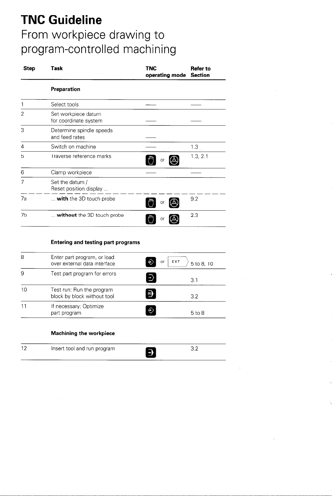
TNC Guideline
3
From workpiece drawing to
program-controlled machining
Step Task
Preparation
1
2
3
4 Switch on machine 1.3
5 Traverse reference marks
6 Clamp workpiece
7 Set the datum /
--- --- --- -----7a
Select tools
Set workpiece datum
for coordinate system
Determine spindle speeds
and feed rates
Reset position display
with the 3D touch probe
TNC Refer to
operating mode Section
J
d
d
7b
8 Enter part program, or load
9 Test part program for errors
10
11 If necessary: Optimize
12 Insert tool and run program 3.2
without the 3D touch probe
Entering and testing pat-t programs
over external data interface m Or /EXT)5to8,10
Test run: Run the program
block by block without tool
part program
Machining the workpiece
z
BJ
3.2
5 to 8
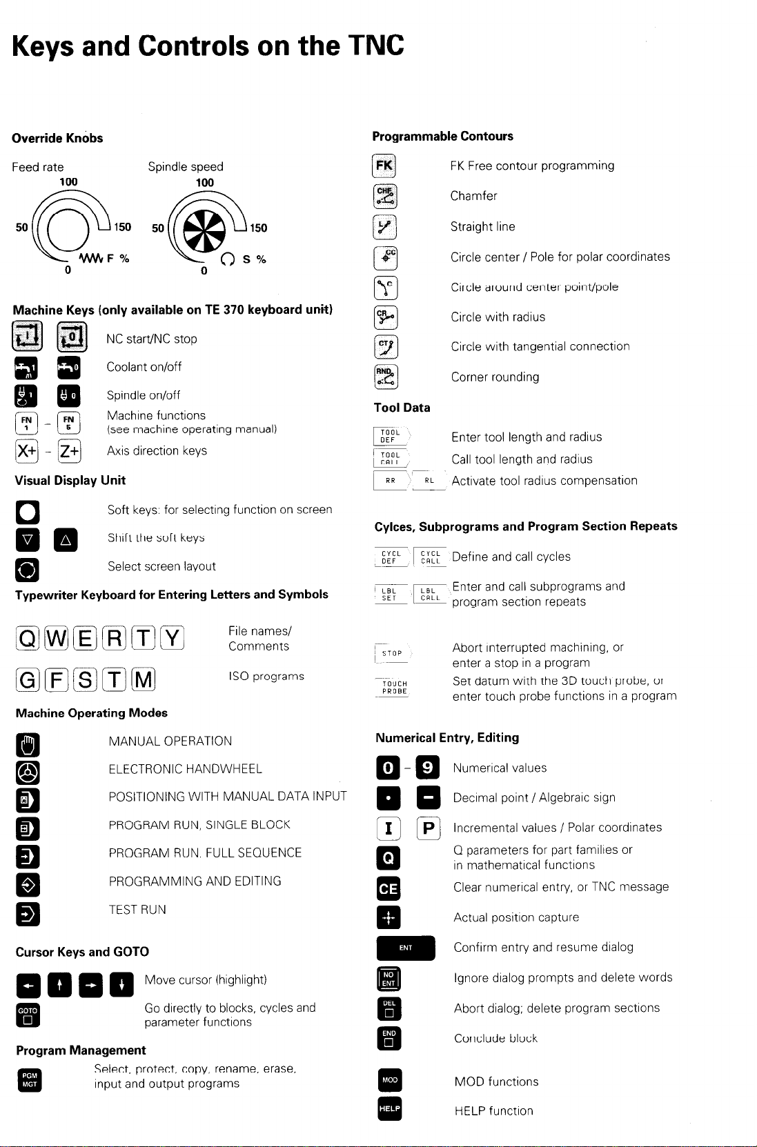
Keys and Controls on the TNC
Override Knobs
Feed rate Spindle speed
100
5oQ: 50@:
0
Machine Keys (only available on TE 370 keyboard unit)
EJl@j
Elm
mm Spindle on/off
W-B
@g-m
Visual Display Unit
0
mm
m
Typewriter Keyboard for Entering Letters and Symbols
NC start/NC stop
Coolant on/off
Machrne functions
(see machine operating manual)
Axis direction keys
Soft keys: for selectrng function on screen
Shaft the soft keys
Select screen layout
100
0
Programmable Contours
FK
0
CHF
.A
0
RWD
od
0
Tool Data
EE&
I- TOOL
w
- ~~
k RL- Activate tool radius compensation
Cylces, Subprograms and Program Section Repeats
E:F’ Eb:: Define and call cycles
%-m
FK Free contour programming
Chamfer
Straight line
Circle center / Pole for polar coordinates
Circle around center point/pole
Circle with radius
Circle with tangential connection
Corner rounding
Enter tool length and radius
Call tool length and radius
Enter and call subprograms and
program section repeats
0 iw] (El (R1 (Tl m p:;;;::
(GjIFj/S)ITj(Mj
Machine Operating Modes
m
f;s1
0
r.1
El
z
a
Q
Q
Q
Cursor Keys and GOT0
0000
. .
m
Program Management
MANUAL OPERATION
ELECTRONIC HANDWHEEL
POSITIONING WITH MANUAL DATA INPUT
PROGRAM RUN, SINGLE BLOCK
PROGRAM RUN, FULL SEQUENCE
PROGRAMMING AND EDITING
TEST RUN
Move cursor (highlight)
Go drrectly to blocks, cycles and
parameter functions
Select, protect, copy, rename, erase,
Input and output programs
IS0 programs
Abort interrupted machrnrng, or
enter a stop in a program
Set datum with the 3D touch probe, or
enter touch probe functions in a program
Numerical Entry, Editing
Numerical values
Decrmal point / Algebrarc sign
Incremental values / Polar coordinates
0 parameters for part familres or
in mathematrcal functions
Clear numerical entry, or TNC message
Actual positron capture
Confirm entry and resume dialog
Ignore dialog prompts and delete words
Abort dialog; delete program sections
Conclude block
MOD functions
HELP function
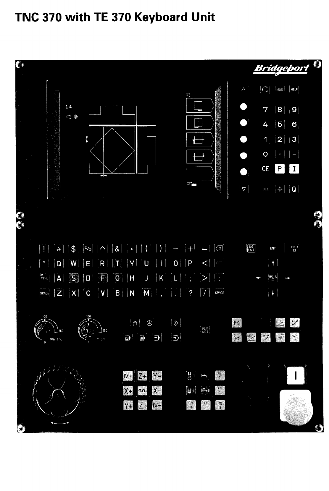
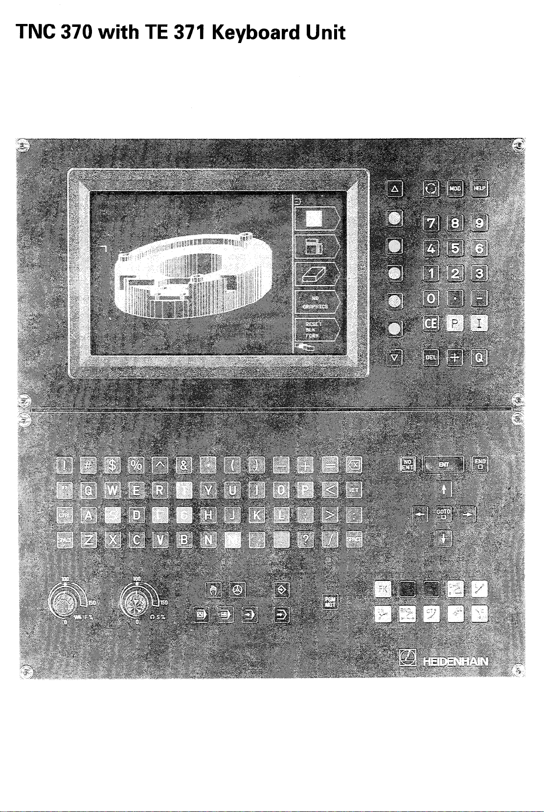
TNC 370 with TE 370 Keyboard Unit
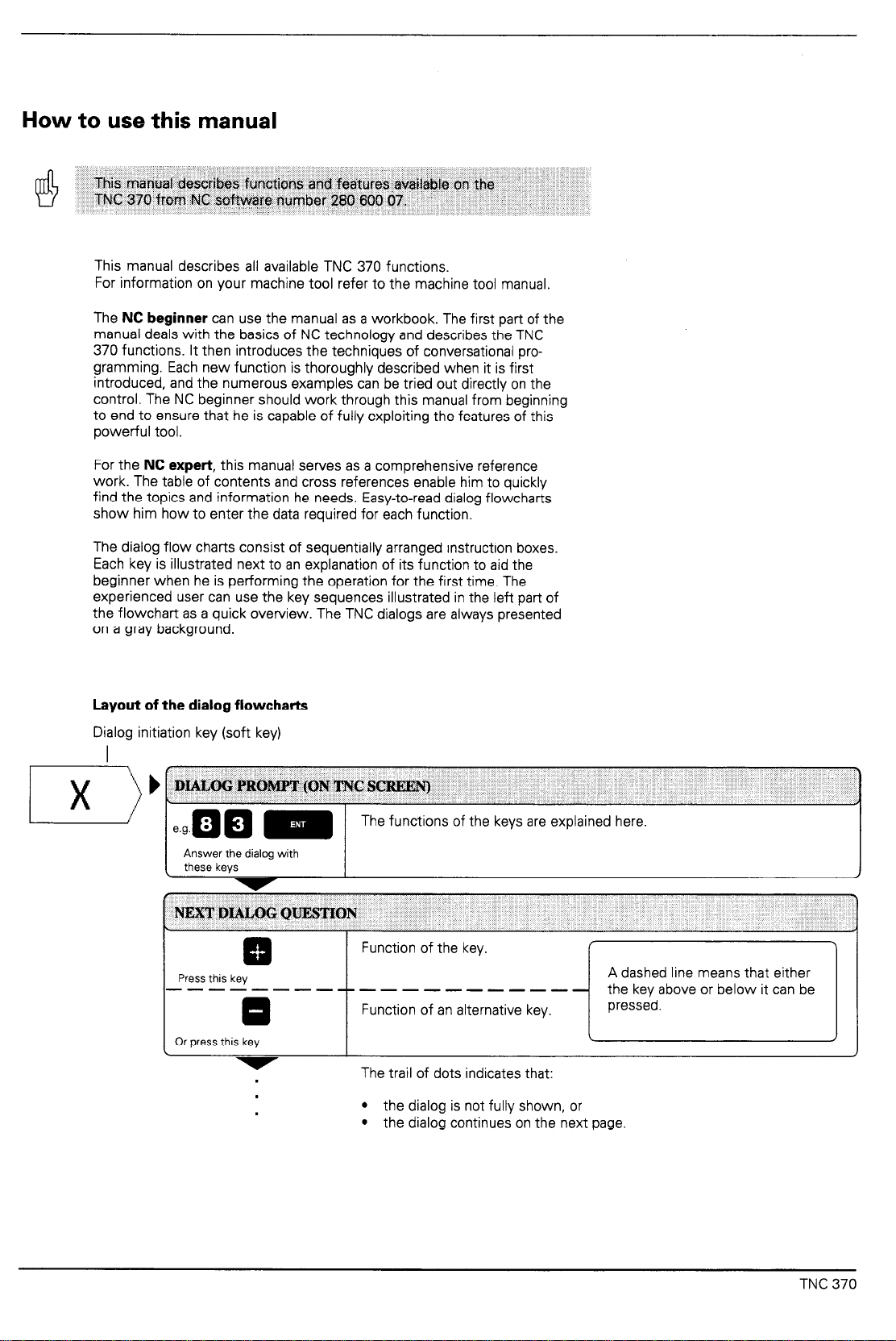
How to use this manual
This manual describes functions and fezitures
TNC 370 from MC so%re
This manual describes all available TNC 370 functions.
For information on your machine tool refer to the machine tool manual.
The NC beginner can use the manual as a workbook. The first part of the
manual deals with the basics of NC technology and describes the TNC
370 functions. It then introduces the techniques of conversational programming. Each new function is thoroughly described when it is first
introduced, and the numerous examples can be tried out directly on the
control. The NC beginner should work through this manual from beginning
to end to ensure that he is capable of fully exploiting the features of this
powerful tool.
For the NC expert, this manual serves as a comprehensive reference
work. The table of contents and cross references enable him to quickly
find the topics and information he needs. Easy-to-read dialog flowcharts
show him how to enter the data required for each function.
The dialog flow charts consist of sequentially arranged instruction boxes.
Each key is illustrated next to an explanation of its function to aid the
beginner when he is performing the operation for the first time. The
experienced user can use the key sequences illustrated in the left part of
the flowchart as a quick overview. The TNC dialogs are always presented
on a gray background.
number 280 K?O Of.
aYailr;tble on the
Layout of the dialog flowcharts
Dialog initiation key (soft key)
I
Answer the dialog with
these keys
I
NEXTDIALOGQUESfJQN
c
Press this key
----------------
0
Or press this key
L
.
.
.
The functions of the keys are explained here.
Function of the key.
A dashed line means that either
Function of an alternative key.
The trail of dots indicates that:
l
the dialog is not fully shown, or
l
the dialog continues on the next page
I
/
TNC 370

Contents User's Manual TNC 370
Introduction
Manual Operation and Setup
Test Run and Program Run
Programming
Programming Tool Movements
Subprograms and Program Section Repeats
Programming with Q Parameters
Cycles
3D Touch Probes
External Data Transfer
MOD-Functions, HELP Functions
1
2
3
4
5
6
7
8
9
10
11
Tabels, Overviews and Dialogs
12
Introduction
1.1 TNC370
The operating panel with the TE 370 keyboard
Soft key structure ......................................................................................................
TNC Accessories
1.2 Fundamentals
Introduction .............................................................................................................
What is NC7 ............................................................................................................
The part program ....................................................................................................
Conversational
Reference system ...................................................................................................
Cartesian coordinate
Additional axes ........................................................................................................
Polar coordinates
Setting a pole at a circle center (CC) .....................................................................
Setting the datum
Absolute workpiece positions..
Incremental workpiece positions..
Programming tool
Position encoders.. ..................................................................................................
Reference marks ....................................................................................................
...............................................................................................
unit.. ...............................................
....................................................................................................
. . . . . . . . . . . . . . . . . . . . . . . . . . . . . . . . . . . . . . . . . . . . . . . . . . . . . . . . . . . . . . . . . . . . . . . . . . . . . . . . . . . 1-18
programming ..................................................................................
system ..................................................................................
.................................................................................................... I-20
....................................................................................................
................................................................................
........................................................................... 1-23
movements.. ..............................................................................
1.3 Switch-On . . . . . . . . . . . . . . . . . . . . . . . . . . . . . . . . . . . . . . . . . . . . . . . . . . . . . . . . . ..*..............................
1-2
1-3
1-7
1-l 7
l-l 8
1-18
l-l 8
l-l 8
l-l 9
1-l 9
I-20
l-21
I-21
1-23
1-25
1-25
1-25
1-26
1.4 Graphics and Status Display
Plan view .................................................................................................................
Projection in three planes
3D View ..................................................................................................................
Repeating graphic simulation..
Status display ..........................................................................................................
Additional status displays.. ......................................................................................
.......................................................................................
. . . . . . . . . . . . . . . . . . . . . . . . . . . . . . . . . . . . . . . . . . . . . . . . . . . . . . . . . . 1-27
................................................................................
1.5 Interactive Programming Graphics ................................................
Generating graphics during programming
Generating graphics for an
Magnifying/reducing a detail ...................................................................................
existing program .........................................................
..............................................................
1.6 Programs ...........................................................................................
Program management
Selecting, protecting,
...........................................................................................
copying, renaming and erasing programs ...........................
1-27
1-28
1-29
I-30
1-31
1-31
1-34
1-34
l-34
1-35
1-36
1-36
1-37
TNC 370
2 Manual Operation and Setup
2.1 Moving the Machine Axes
Traversing with the axis direction keys .....................................................................
Traversing with the electronic handwheel
Working with the HR 330 electronic handwheel .......................................................
Positioning with manual data input ...........................................................................
Incremental jog positioning .......................................................................................
.................................................................
................................................................ 2-3
2.2 Spindle Speed S, Feed Rate F and Miscellaneous Functions
To enter the spindle speed S ....................................................................................
To change the spindle speed S
To change the feed rate F
To enter the miscellaneous function M
2.3 Setting the Datum without a 3D Touch Probe
Setting the datum in the tool axis ............................................................................
Setting the datum in the working plane
................................................................................
........................................................................................ 2-6
.....................................................................
.................................
.................................................................... 2-8
M
...
2-2
2-2
2-3
2-4
2-4
2-5
2-5
2-5
2-6
2-7
.2-7
TNC 370
3 Test Run and Program Run
3.1
3.2
3.3
3.4
3.5
Test Run
To do a test run
Program Run
To run a part program ................................................................................................ 3-3
Interrupting machining .............................................................................................. 3-4
Resuming program run after an interruption
Blockwise Transfer: Executing Long Programs
Skipping Blocks During Program Run/Test Run
..............................................................................................
......................................................................................................... 3-2
........................................................................................
............................................................. 3-5
................................ 3-6
............................ 3-7
Optional Interruption of a Program Run ..........................................
3-2
3-3
3-7
4 Programming
4.1
Editing
Part Programs
Layout of a program.. ...............................................................................................
Plain language dialog
Editing functions .......................................................................................................
.......................................................................
...............................................................................................
4.2 Tools ....................................................................................................
Determining tool data ...............................................................................................
Oversizes for lengths and radii - delta values..
Entering tool data into the program .........................................................................
Entering tool data in program
Entering tool
Pocket table
Calling tool data ......................................................................................................
Tool change ...........................................................................................................
data in tables ......................................................................................
for tool changer ................................................................................. .4-l 2
TO0L.T
....................................................................
........................................................
4-2
.4-2
.4-2
,4-3
4-5
,4-5
4-6
.4-7
.4-8
.4-9
4-l 3
.4-l 4
4.3 Tool Compensation Values ............................................................. 4-15
Effect of tool compensation values..
Tool radius compensation ......................................................................................
Machining corners
..................................................................................................
......................................................................
4.4 Program Creation .............................................................................
.4-l 5
.4-l 6
.4-l 8
4-19
Creating a new
Defining the blank form
part program
.................................................................................
..........................................................................................
,4-l 9
.4-l 9
4.5 Entering Tool-Related Data ............................................................. 4-21
Feed rate
Spindle speed S ......................................................................................................
F
.............................................................................................................
.4-21
4-22
4.6 Entering Miscellaneous Functions and STOP . . . . . . . . . . . . . . . . . . . . . . . . . . . . . . 4-23
4.7 Actual Position Capture . . . . . . . . . . . . . . . . . . . . . . . . . . . . . . . . . . . . . . . . . . . . . . . . . . . . . . . . . . . . . . . . . . . 4-24
4.8 Marking
Blocks to be Skipped . . . . . . . . . . . . . . . . . . . . . . . . . . . . . . . . . . . . . . . . . . . . . . . . . . . . . . . . 4-25
4.9 Entering Comments in the Part Program ..*.......................*............ 4-26
TNC 370
Programming Tool Movements
5.1
General Information on Programming Tool Movements..
5.2 Contour Approach and Departure
Starting and end positions
Smooth approach and departure ..............................................................................
.......................................................................................
.................................................... 5-4
..............
5.3 Path Functions ....................................................................................
General information ................................................................................................. .5-7
Machine axis movement under program control ..................................................... .5-7
Overview of path functions ....................................................................................... 5-8
5.4 Path Contours - Cartesian Coordinates
Straight line
Chamfer ..................................................................................................................
Circles and circular arcs - General information
Circle center CC ...................................................................................................... 5-1 5
Circular path C around the circle center CC..
Circular path CR with defined radius ...................................................................... 5-20
Circular path CT with tangential connection .......................................................... .5-23
Corner rounding RND
.............................................................................................................. .5-9
.............................................................................................
........................................ 5-9
.....................................................
.........................................................
5-2
.5-4
5-6
5-7
5-l 2
5-14
5-l 7
5-25
5.5 Path Contours -
Polar coordinate origin: Pole CC.. .......................................................................... .5-27
Straight line
Circular path CP around pole CC ........................................................................... 5-30
Circular path CTP with tangential connection..
Helical interpolation ................................................................................................. 5-33
5.6 Contours - FK Free Contour Programming
Programming contour elements with FK ................................................................
Interactive graphics during FK programming
FK Functions .......................................................................................................... .5-39
Free programming of straight lines
Free programming of circular arcs.. ........................................................................ 5-44
Identifying closed contours .....................................................................................
Polar Coordinates .............................................. 5-27
LP
........................................................................................................
.......................................................
...................................
.........................................................
.........................................................................
5-27
5-32
5-36
5-36
5-38
5-40
5-47
5.7 M Functions for Contouring Behavior and Coordinate Data ....... 5-51
Smoothing corners: M90..
Machining small contour steps: M97
Complete machining of open contours: M98 ......................................................... .5-53
Setting the coordinates for the datum: M91/M92 .................................................. .5-54
Reducing rotary axis display values to under 360”: M94 ...................................... .5-55
Optimized traverse of rotary axes: Ml 26 ............................................................... 5-55
Feed rate at circular arcs: Ml 09/Ml IO/Ml 11 ........................................................ 5-56
.......................................................................................
......................................................................
5-51
5-52
5.8 Positioning with Manual Data Input (MDI)
......................................
5-57
6 Subprograms and Program Section Repeats
6.1 Subprograms
Principle .................................................................................................................... 6-2
Operating limits ......................................................................................................... 6-2
Programming and calling subprograms
................................................................. . ....................
6.2 Program Section Repeats
Principle
Programming notes..
Programming and calling a program section repeat ................................................
.................................................................................................................... 6-5
................................................................................................. 6-5
6.3 Program as Subprogram
Principle .................................................................................................................... 6-8
Operating limits ......................................................................................................... 6-8
Calling a program as a subprogram ......................................................................... 6-8
6.4 Nesting
Nesting depth
Subprogram in a subprogram ................................................................................... 6-9
Repeating program section repeats
Repeating subprograms .......................................................................................... 6-l 2
................................................................................................ 6-9
...........................................................................................................
6-2
.................................................................... 6-3
................................................................. 6-5
6-5
................................................................... 6-8
.6-9
.......................................................................
6-l 1
TNC 370 -
7 Programming with Q Parameters
7.1
7.2
7.3
7.4
7.5
7.6
Part Families - Q Parameters Instead of Numerical Values..
Describing Contours Through
Overview
...................................................................................................................
Mathematical
Functions ................ 7-6
...... 7-4
7-6
Trigonometric Functions ................................................................... 7-8
Overview ..................................................................................................................
If-Then Operations with Q Parameters
Jumps ...................................................................................................................
Overview ..................................................................................................................
Checking and Changing Q
Parameters ......................................... 7-11
Output of Q Parameters and Messages
Displaying error messages ....................................................................................
Output through an external data interface..
Assigning values for the
PLC
..................................................................................
............................................ 7-9
......................................... 7-12
............................................................
.7-8
,7-9
.7-9
.7-l 2
7-l 3
7-l 3
7.7
7.8
Reading from System Data ..................
Examples for Exercise.. ...................................................................
Rectangular pocket with corner rounding and tangential approach
Bolt hole circle ........................................................................................................
Ellipse
Machining a hemisphere with an end mill
..................................................................................................................
..* ......................................... 7-14
7-15
....................... 7-l 5
.7-l 6
..............................................................
.7-20
7-l 8
8 Cycles
8.1
8.2
8.3
General Overview of Cycles .............................................................. 8-2
Programming a cycle ...............................................................................................
Drilling Cycles
PECKING (Cycle 1) .................................................................................................
DRILLING (Cycle 200) ............................................................................................. .8-7
REAMING (Cycle 201) .............................................................................................
BORING (Cycle 202) ............................................................................................... .8-9
UNIVERSAL DRILLING CYCLE (Cycle 203) ........................................................ .8-l 0
TAPPING with a floating tap holder (Cycle 2) ....................................................... .8-l 2
RIGID TAPPING (Cycle 17). ...................................................................................
Examples for exercise.. ..........................................................................................
....................................................................................
.8-3
8-5
.8-6
.8-8
8-13
.8-l 4
Cycles for Milling Pockets, Studs and Slots ................................. 8-16
POCKET MILLING (Cycle 4) ................................................................................. .8-17
POCKET FINISHING (Cycle
STUD FINISHING (Cycle 213) ...............................................................................
CIRCULAR POCKET MILLING (Cycle 5). ............................................................. .8-22
CIRCULAR POCKET FINISHING
CIRCULAR STUD FINISHING (Cycle 215) ........................................................... ,8-25
SLOT MILLING (Cycle 3). ......................................................................................
SLOT with reciprocating plunge-cut
CIRCULAR SLOT with reciprocating plunge-cut (Cycle 210) ................................ 8-30
Examples for exercise.. .......................................................................................... .8-32
212) ......................................................................... .8-18
8-20
(Cycle 214) ...................................................... .8-23
.8-27
(Cycle
210) ...................................................
.8-28
8.4
8.5
8.6
8.7
8.8
Cycles for Machining Hole Patterns ............................................... 8-34
CIRCULAR PATTERN (Cycle 220) ....................................................................... .8-35
LINEAR PATTERN (Cycle 221) ..............................................................................
Examples for exercise.. .......................................................................................... .8-38
8-36
SL Cycles .......................................................................................... 8-40
CONTOUR GEOMETRY (Cycle 14). ...................................................................... 8-41
ROUGH-OUT (Cycle 6) .........................................................................................
SL Cycles: Overlapping contours .......................................................................... .8-44
PILOT DRILLING (Cycle 15)
CONTOUR MILLING (Cycle 16). ........................................................................... .8-51
................................................................................. .8-50
.8-42
Cycles for Multipass Milling ............................................................ 8-54
MULTIPASS MILLING (Cycle 230) ........................................................................ 8-55
RULED SURFACE (Cycle 231) .............................................................................. 8-57
Examples for exercise.. ..........................................................................................
.8-59
Cycles for Coordinate Transformations ........................................ 8-60
DATUM SHIFT (Cycle 7) ........................................................................................ 8-61
MIRROR IMAGE (Cycle 8) ....................................................................................
ROTATION (Cycle IO) ........................................................................................... .8-65
SCALING FACTOR (Cycle 1 1) ..............................................................................
.8-63
.8-66
Special Cycles .................................................................................. 8-68
DWELL TIME (Cycle 9).
PROGRAM CALL (Cycle 12)
ORIENTED SPINDLE STOP
.........................................................................................
.8-68
.................................................................................. 8-68
(Cycle 13). ............................................................... .8-69
TNC 370
9 3D Touch Probes
9.1
9.2
9.3
9.4
General Information on Touch Probes
TS 120 Triggering touch probe ................................................................................ .9-2
TS 630 Triggering touch probe ................................................................................. 9-2
lT 120 Touch probe for tool measurement.. ...........................................................
............................................. 9-2
Touch Probe Cycles in the MANUAL and
ELECTRONIC HANDWHEEL Operating Modes
To select the touch probe functions ......................................................................... 9-4
Calibrating a triggering 3D touch probe .................................................................... 9-5
Compensating workpiece misalignment ................................................................... 9-7
Setting the datum with the 3D touch probe system .................................................
............................... 9-4
Measuring Workpieces with a 3D Touch Probe ............................
Finding the coordinate of a position on an aligned workpiece ............................... 9-l 4
Finding the coordinates of a corner in the working plane ....................................... 9-14
Measuring workpiece dimensions. .......................................................................... 9-l 5
Measuring angles ...................................................................................................
Measuring with the 3D touch probe during program run ....................................... .9-18
Digitizing with a Triggering 3D Touch Probe (Optional)
Defining the digitizing range.. .................................................................................
Input data ............................................................................................................... .9-22
Setting the scanning range ....................................................................................
Line-by-line digitizing with Cycle 6 MEANDER ....................................................... 9-24
Contour line digitizing with Cycle 7 CONTOUR LINES ......................................... .9-26
Input data ................................................................................................................ 9-27
.............. 9-21
.9-3
9-9
9-14
.9-l 6
.9-22
.9-22
9.5
9.7
Using Digitized Data in a Part Program
Executing a part program from digitized data .......................................................
......................................... 9-29
Measuring Tools with the TT 120 Touch Probe ............................
Calibrating the TT 120 ............................................................................................ 9-33
Measuring the tool length ....................................................................................... 9-34
Measuring the tool radius .......................................................................................
.9-30
9-31
9-36
External Data Transfer
10.1 Functions for External Data Transfer
Blockwise transfer ................................................................................................... 1 O-2
.............................................
10.2 Pin Layout and Connecting Cable for Data Interface
RS-232-C/V.24 Interface ..........................................................................................
10.3 Preparing the Devices for Data Transfer
HEIDENHAIN devices
Non-HEIDENHAIN devices ...................................................................................... IO-4
............................................................................................. IO-4
.........................................
....................
IO-2
.lO-3
1 O-3
10-4
TNC 370
11 MOD Functions, HELP Functions
11.1 Calling and Exiting the MOD Functions
11.2 Machine-Specific User Parameters
. . . . . . . . . . . . . . . . . . . . . . . ..m..................*...
. . . . . . . . . . . . . . . . . . . . . . . . . . . . . . . . . . . . . . . . .
11-2
11-2
11.3 Selecting the Programming Format and Unit of Measure............ 11-3
11.4 Setting the Axis Traverse Limits
11.5 Setting the External Data Interface
RS-232-C Interface ................................................................................................. 1 1-5
BAUD RATE ............................................................................................................
11.6 Selecting Position Display Types
11.7 Code Numbers
..................................................................................
. . . . . . . . ..~.........................................
.................................................
...................................................
11-4
11-5
1 1-5
11-6
11-7
11.8 NC and PLC Software Numbers, Free Memory
.........................................
11.9 HELP Function ........................................
Selecting and exiting HELP .................................................................................... 1 l-8
.
.............................
11-7
11-8

12 Tables, Overviews and Dialogs
12.1 General User Parameters .......................................
Selecting the general user parameters. ..................................................................
External data transfer
3D Touch probes and digitizing ..............................................................................
TNC displays, TNC editor
Machining and program run
Override behavior, electronic handwheel ............................................................... 12-9
12.2 Miscellaneous Functions (M Functions)
Miscellaneous functions with predetermined effect.
Vacant miscellaneous functions
12.3 Preassigned Q Parameters
12.4 Features, Specifications and Accessories
Accessories ........................................................................................................... 12-l 6
12.5 TNC Error Messages
TNC error messages during programming
TNC error messages during test run and program run ........................................
TNC error messages during digitizing
............................................................................................. 12-3
....................................................................................... 12-6
.................................................................................... 12-8
....... . .............................. 12-10
............................................. 12-l 0
...........................................................................
. . . . . . . . . . . . . . . . . . . . . . . . . . . . . . . . . . . . . . . . . . . . . . . . . . . . . . . . . . .
.................................. 12-14
......................................................................
...........................................................
..................................................................
. ........................
12-2
12-2
12-4
12-l 1
12-12
12-17
12-l 7
12-18
12-21
TNC 370
1 Introduction
1.1 TNC 370
The operating panel with the TE 370 keyboard unit
Soft key structure
TNC Accessories ....................................................................................................
...............................................................................................
1.2 Fundamentals
introduction .............................................................................................................
What is NC? ............................................................................................................
The part program
Conversational programming
Reference system ...................................................................................................
Cartesian coordinate system
Additional axes .......................................................................................................
Polar coordinates .................................................................................................... I-20
Setting a pole at a circle center (CC)
Setting the datum ...................................................................................................
Absolute workpiece positions
Incremental workpiece positions ............................................................................
Programming tool movements
Position encoders ...................................................................................................
Reference marks ...................................................................................................
1.3 Switch-On
...............................................
..................................................................................................... 1-7
...................................................................................
.................................................................................................... l-l 8
................................................................................. l-l 8
................................................................................. l-l 9
.................................................................... 1-21
.................................................................................
............................................................................... 1-25
..........................................................................................
1-2
1-3
l-l 7
1-18
1-I 8
l-l 8
l-l 9
I-20
I-21
l-23
I-23
1-25
I-25
1-26
1.4 Graphics and Status Display
Plan view .................................................................................................................
..................................................................................... I-28
................................................................................. I-30
1.5
1.6
Projection in three planes..
3D View ..................................................................................................................
Repeating graphic simulation
Status display .........................................................................................................
Additional status displays .......................................................................................
Interactive Programming Graphics
Generating graphics during programming
Generating graphics for an existing program
Magnifying/reducing a detail ..................................................................................
Programs..
Program management ..........................................................................................
Selecting, protecting, copying, renaming and erasing programs
.........................................................................................
..........................................................
................................................
............................................................. I-34
........................................................ 1-34
.........................
I-27
1-27
1-29
1-31
1-31
l-34
I-35
1-36
1-36
I-37
1
Introduction
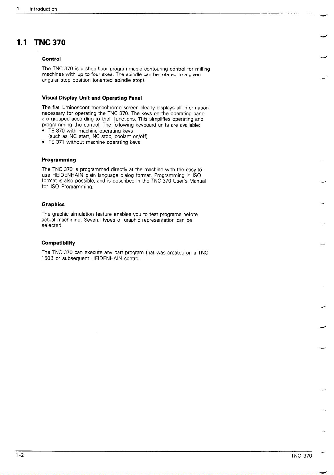
1.1 TNC 370
Control
The TNC 370 is a shop-floor programmable contouring control for milling
machines with up to four axes. The spindle can be rotated to a given
angular stop position (oriented spindle stop).
Visual Display Unit and Operating Panel
The flat luminescent monochrome screen clearly displays all information
necessary for operating the TNC 370. The keys on the operating panel
are grouped according to their functions. This simplifies operating and
programming the control. The following keyboard units are available:
l
TE 370 with machine operating keys
(such as NC start, NC stop, coolant on/off)
l
TE 371 without machine operating keys
Programming
The TNC 370 is programmed directly at the machine with the easy-to-
use HEIDENHAIN plain language dialog format. Programming in IS0
format is also possible, and is described in the TNC 370 User’s Manual
for IS0 Programming.
4
Graphics
The graphic simulation feature enables you to test programs before
actual machining. Several types of graphic representation can be
selected.
Compatibility
The TNC 370 can execute any part program that was created on a TNC
150B or subsequent HEIDENHAIN control.
1-2 TNC 370 .-
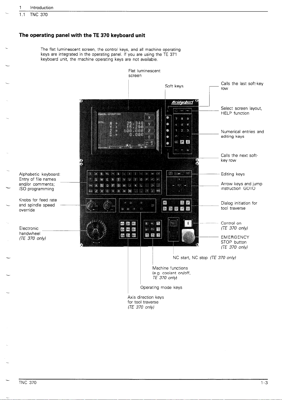
1 Introduction
1 .I TNC 370
The operating panel with the TE 370 keyboard unit
The flat luminescent screen, the control keys, and all machine operating
keys are integrated in the operating panel. If you are using the TE 371
keyboard unit, the machine operating keys are not available.
Flat luminescent
screen
Soft keys
!
Calls the last soft-key
row
r
Select screen layout,
HELP function
Numerical entries and
editing keys
Alphabetic keyboarl
Entry of file names
and/or comments;
IS0 programming
Knobs for feed rate
and spindle speed
override
Electronic
handwheel
(TE 370 only)
d:
Calls the next softkey row
Editing keys
Arrow keys and jump
instruction GOT0
Dialog initiation for
tool traverse
Control on
(TE 370 only)
EMERGENCY
STOP button
(TE 370 only)
NC start, NC stop (TE 370 only)
Machine functions
(e.g. coolant on/off,
TE 370 only)
Operating mode keys
TNC 370
Axis direction keys
for tool traverse
(TE 370 only)
1-3
1 Introduction
1.1 TNC 370
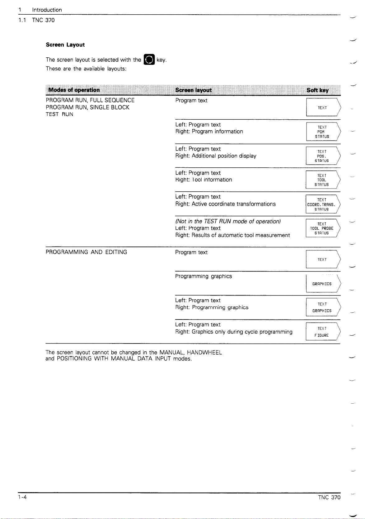
Screen Layout
-/
J
The screen layout is selected with the
These are the available layouts:
Modes of apcarcvtion
PROGRAM RUN, FULL SEQUENCE
PROGRAM RUN, SINGLE BLOCK
TEST RUN
key.
!breen layout
Program text
Left: Program text
Right: Program information
Left: Program text
Right: Additional position display
Left: Program text
Right: Tool information
Left: Program text
Right: Active coordinate transformations
(Not in the TEST RUN mode of operation)
Left: Program text
Right: Results of automatic tool measurement
.,
-/
-
-/
.-
PROGRAMMING AND EDITING
Program text
Programming graphics
Left: Program text
Right: Programming graphics
Left: Program text
Right: Graphics only during cycle programming
The screen layout cannot be changed in the MANUAL, HANDWHEEL
and POSITIONING WITH MANUAL DATA INPUT modes.
-
1
-/
d
1-4
TNC 370 -
i-
1 Introduction
1.1 TNC 370
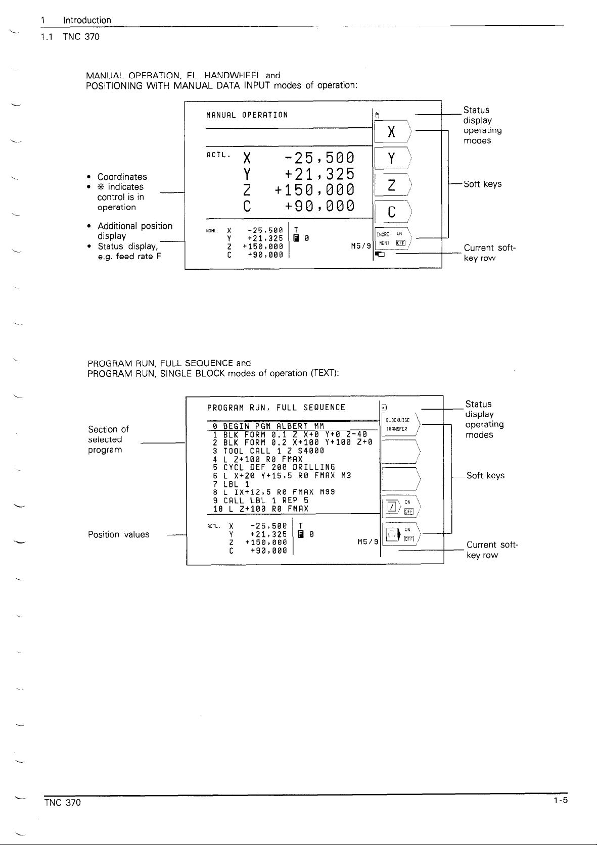
MANUAL OPERATION, EL. HANDWHEEL and
POSITIONING WITH MANUAL DATA INPUT modes of operation:
MRNURL OPERRTION
ACTL.
l
Coordinates
l
t indicates
control is in
operation
l
Additional position
display
l
Status display,
e.g. feed rate F
PROGRAM RUN, FULL SEQUENCE and
PROGRAM RUN, SINGLE BLOCK modes of operation (TEXT):
NOHL. x
X
Y
2
-25,580 1 y ;,
+21,325
+1509080 2 ';‘
c +909000 c ‘)
I
-25,588 T
Y
+21,325 I a
+150,008 H5/9
f
+90,068
R -
II
i.
if
__ Status
display
operating
modes
-Soft keys
Current soft-
- key row
Section of
selected
program
Position values
PROGRRM RUN, FULL SEQUENCE
5
CYCL DEF 268
I
Status
display
operating
modes
DRILLING
-Soft keys
Current softkey row
L
L
TNC 370
1-5

1
Introduction
1.1 TNC 370
PROGRAMMING AND EDITING mode of operation (TEXT+GRAPHICS):
PROGRRMMING RN0 EDITING
Section of selected
program at left, -
graphics at right
ICTL. x
Position values _
TEST RUN operating mode (GRAPHICS):
Test graphics
or section of
the selected
program
-25,506 T
+21,325
r
+15o,oaB M5/9
C
+9a,aaa
3 GRA
I, ~-
0 0 )--
Q=e -
-Status
display
operating
modes
-Soft keys
Current soft-
- key row
_ Status
display
operating
modes
Soft keys
_ Current soft-
key row
l-6
TNC 370 -
L
1 Introduction
1.1 TNC 370
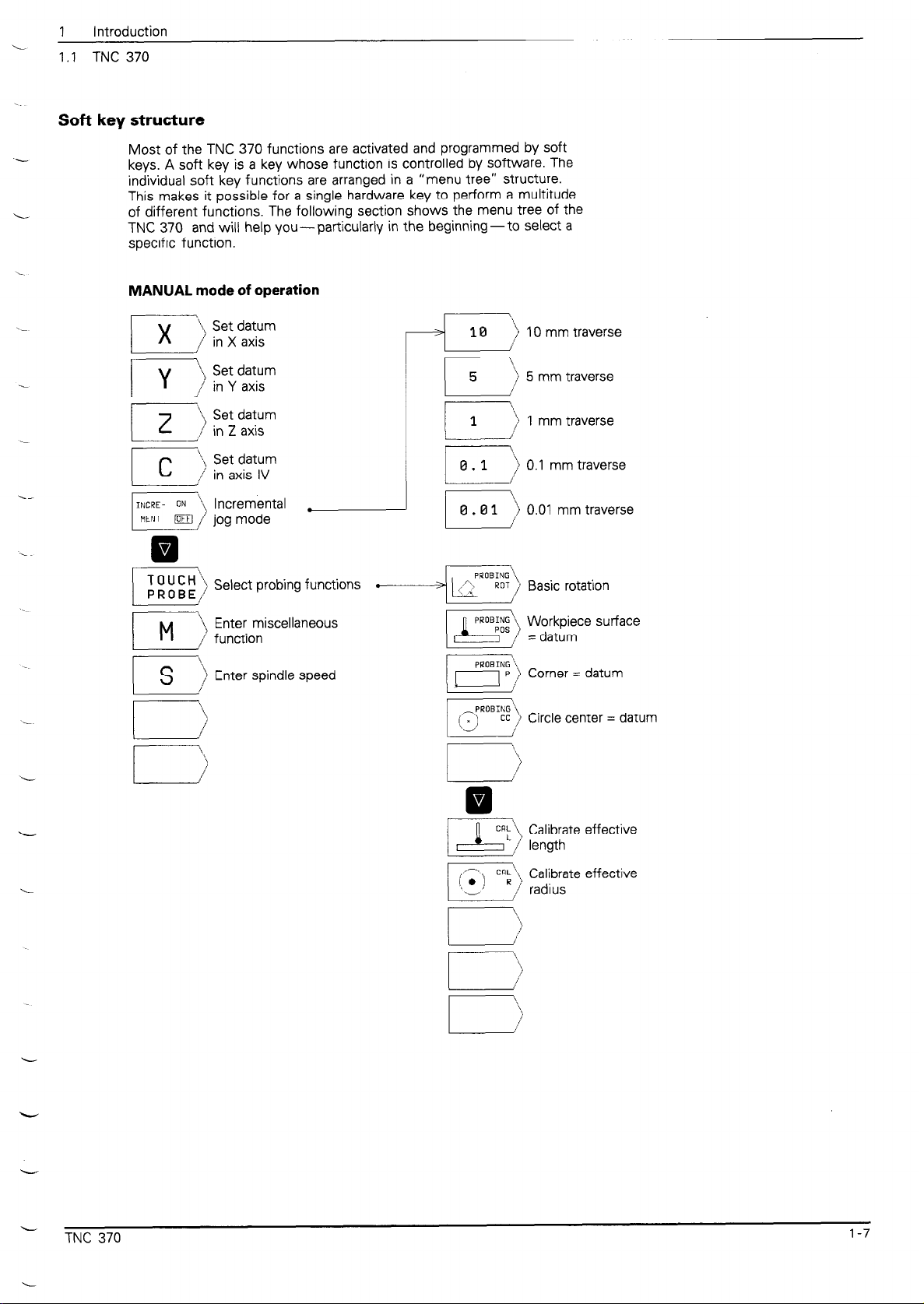
Soft key structure
Most of the TNC 370 functions are activated and programmed by soft
keys. A soft key is a key whose function is controlled by software. The
individual soft key functions are arranged in a “menu tree” structure.
This makes it possible for a single hardware key to perform a multitude
of different functions. The following section shows the menu tree of the
TNC 370 and will help you-particularly in the beginning-to select a
specific function.
MANUAL mode of operation
v
0
Set datum
in X axis
Select probing functions
‘\
10
4
I
L-
r
0.1
0.01
1 IOmm / traverse
\
5
: 5 mm traverse
:
1 \,
1 mm traverse
,.a’
‘\
,) 0.1 mm traverse
\
i 0.01 mm traverse
L-J
--
( , 1 PRO,,,,)
Workpiece surface
= datum
Corner = datum
Circle center = datum
L
TNC 370
Calibrate effective
length
Calibrate effective
radius
1-7

1 Introduction
1.1 TNC 370
ELECTRONIC HANDWHEEL mode of operation
Set datum in X axis
x 1
tz
y ‘)
I----
I 2
r
0
L-IQ
with handwheel
Set datum in Y axis
with handwheel
\
Set datum in 2 axis
with handwheel
/
Set datum in axis IV
with handwheel
incremental .
jog mode
Select probing functions
Enter miscellaneous
function
Enter spindle speed
10 mm traverse
5 mm traverse
mm traverse
0.1 mm traverse
0.01 mm traverse
pRoB;$ ,) y;;;or;ce surface
i
Corner = datum
Circle center = datum
CRL’\. Calibrate effective
l&Z1 C$\ Cal!brate effective
I
/’ radrus
1-8
TNC 370 -
---
1
Introduction
1.1 TNC 370
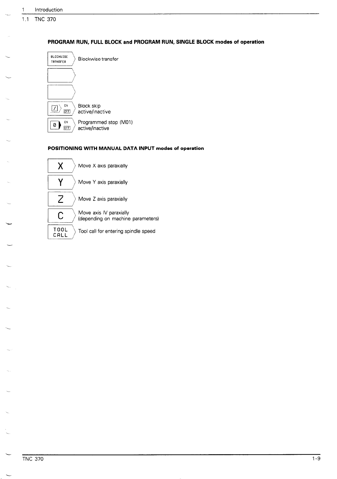
PROGRAM RUN, FULL BLOCK and PROGRAM RUN, SINGLE BLOCK modes of operation
i
\-
POSITIONING WITH MANUAL DATA INPUT modes of operation
I y
2
r-
Blockwise transfer
Move X axis paraxially
\
Move Y axis paraxially
i
:)
Move Z axis paraxially
Move axis IV paraxially
(depending on machine parameters)
Tool call for entering spindle speed
TNC 370
1-9
1 Introduction
1.1 TNC 370
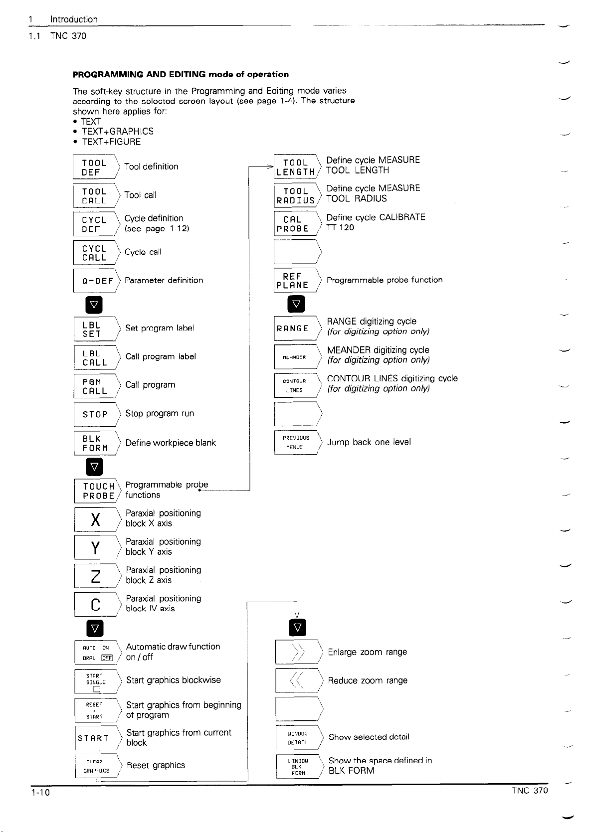
PROGRAMMING AND EDITING mode of operation
The soft-key structure in the Programming and Editing mode varies
according to the selected screen layout (see page l-4). The structure
shown here applies for:
l
TEXT
l
TEXT+GRAPHICS
l
TEXT+FIGURE
4
d
4
I
I\ Define cycle MEASURE
RBIUS/ TOOL RADIUS
IR,
\$ Define cycle CALIBRATE
i l-r120
Programmable probe function
v
0
Set program label
Call program label
Stop program run
Define workpiece blank
r---y
i)
RANGE digitizing cycle
(for digitizing option only)
MEANDER digitizing cycle
(for digitizing option only)
\ CONTOUR LINES digitizing cycle
/ (for digitizing option only)
Jump back one level
_-
_
-
-
-i
v
0
I-IO
Paraxial positioning
Paraxial positioning
v
0
Automatic draw function
on /off
Start graphics blockwise
Start graphics from beginning
Start graphics from current
! Enlarge zoom range
Reduce zoom range
-
Show selected detail
Show the space defined in
TNC 370 -
.-
1
Introduction
1 .I TNC 370
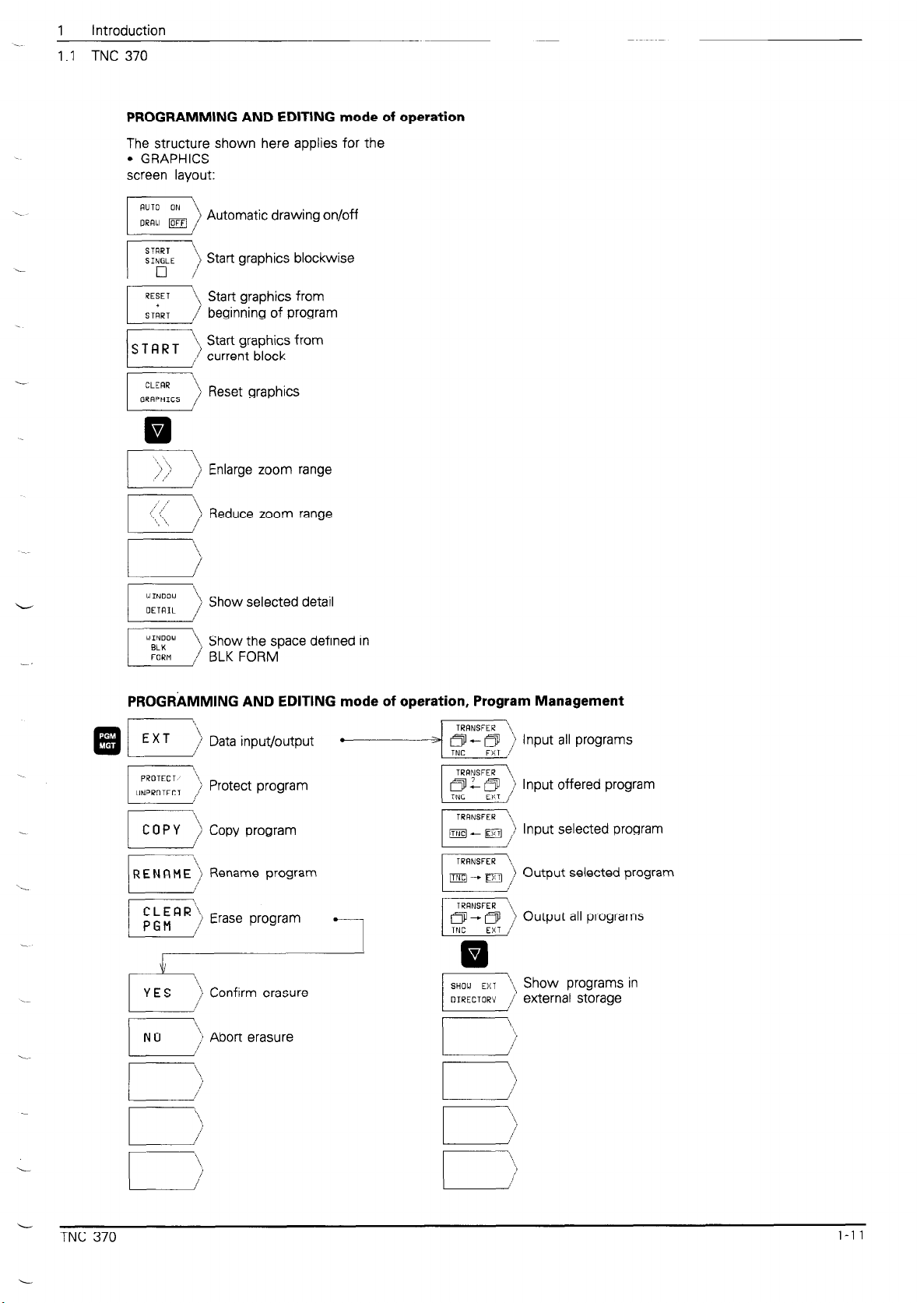
PROGRAMMING AND EDITING mode of operation
The structure shown here applies for the
l
screen layout:
GRAPHICS
Automatic drawing on/off
Start graphics blockwise
Start graphics from
beginning of program
s T FI R T
‘1, Start graphics from
/ current block
Reset graphics
Enlarge zoom range
I ,’
,. ’ /’
‘, \
‘*, ‘,
WINOO,.
OETRIL /
WINDOW \
BLK
FORM
Reduce zoom range
)
‘\
Show selected detail
1
Show the space defined in
/
BLK FORM
PROGRnMMlNG AND EDITING mode of operation, Program Management
@ E> Data input/output
) Protect program
l
Input offered program
L
TNC 370
Input selected program
Rename program
y) Erase program FJ) Output all programs
-
Output selected program
i,, Show programs in
N 0
‘i Abort erasure
/
I
\\,
/
l-l 1
 Loading...