

Page 1

Technical Manual
TNC 360
Valid for the NC software types
259 90 up to version 06
260 02 up to version 17
280 49 up to version 17
260 060 up to version 17
280 610 up to version 17
April 1996
(208 793 E1)
208 793 21 · 3.3 · 4/96 · S · Printed in Germany · Subject to change without notice
Page 2

Preface
This Technical Manual is intended for all manufacturers and distributors of machine tools. It
contains all the necessary information for the assembly, electrical installation, start-up and PLC
programming for the HEIDENHAIN contouring controls TNC 360.
Whenever HEIDENHAIN improves the hardware or software in these controls you will receive a free
delivery of updated information. Please arrange and insert this updated information in your manual
without delay. This will ensure that your manual always remains at the current revision level.
You can use extracts from this manual for your machine documentation. An enlargement of the
manual format (17 cm x 24 cm) by a factor of 1.225 will produce pages in A4 format.
No manual can be perfect. Like all living things it must grow and change. Among other things, it
lives from your impulses and suggestions for improvement. Please help us by giving us your ideas.
DR. JOHANNES HEIDENHAIN GmbH
Department E/P
PO Box 1260
83292 Traunreut
Germany
8/95 TNC 360
Page 3

Contents Technical Manual TNC 360
Update Information
Introduction
Mounting and Electrical Installation
Machine Integration
Machine Parameters
Markers and Words
PLC Programming
Data interfaces
Original Equipment Manufacturer’s (OEM) Cycles
Positioning Module
Appendix
1
2
3
4
5
6
7
8
9
10
11
Page 4
Update Information No. 8
In mid February 1996 software version 17 was released for the NC software types 260 02 and 280
49, and for the newly introduced software types 260 060 (for 1 MB EPROMs) and 280 610 (for 2 MB
EPROMs). The new software types were introduced for the Polish conversational language.
Software version 17 contains the following additions:
• The software now supports the new handwheel HR 410.
The HR 410 is a portable electronic handwheel with:
Keys for selection of five axes
Keys for traverse direction
Keys for three pre-programmed feed rates for latched traverse
One key for actual-position capture
Three keys for machine functions determined by the machine manufacturer
Two permissive buttons
Emergency stop button
Magnetic holding pads
With MP7640 = 6 you can activate the functions for the HR410 handwheel.
MP7645.0 determines whether the keys on the handwheel are assigned to the NC or the PLC.
MP7645.0 = 0
NC key assignment
XIV
YV
ACTUAL
Z
LOW FEED
RATE
MEDIUM
FEED RATE
POSITION
CAPTURE
HIGH FEED
RATE
Handwheel
control panel
–+
O109
I173
With the exception of the A, B and C function
keys, all keys are assigned to the NC.
MP7670.x determines the interpolation factor
for low, medium and high speeds. MP7671.x
determines the low, medium and high speed
values. The speed is given as a percentage factor
of the manual feed rate (MP1020.x).
O110
I174
O111
I175
MP7645.0 = 1
PLC key assignment
O96
I160
O98
I162
O100
I164
O104
I168
I171 I172
O109
I173
All keys are assigned to the PLC. Handwheel
axis and handwheel interpolation are set by
module 9036. With W766 you can change the
feed rate by pressing the axis direction keys.
O105
I169
O110
I174
O97
I161
O99
I163
O103
I167
O106
I170
O111
I175
4/96 TNC 360 Update Information No. 8 1-1
Page 5
MP7670 Interpolation factor for handwheel
1
Input: 0 to 10
MP7670.0 Interpolation factor for low speed
MP7670.1 Interpolation factor for medium speed
MP7670.2 Interpolation factor for high speed
MP7671 Manual feed rate in "handwheel" operating mode with HR 410
Input: 0 to 1000 [% to MP1020]
MP7670.0 Low speed
MP7670.1 Medium speed
MP7670.2 High speed
A dummy plug (Id.-Nr. 271 958 03) is available for an EMERGENCY STOP.
There are connecting terminals on the adapter for the contacts from the emergency stop button
and the permissive buttons (maximum load 1.2 A)
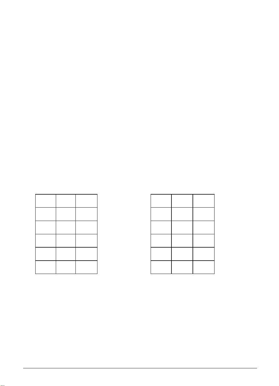
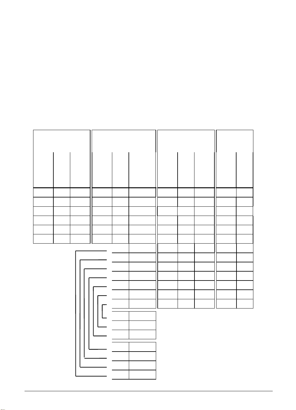
Connector layout:
VL ID number 281 429.. KA ID number 296 466.. VB ID number 296 467 05 HR 410
ID number
296 469 01
D-sub
connector
(male
)
9-pin
D-sub
connector
(female
9-pin
Housing Shield Housing Housing Shield Housing Housing Shield Housing Housing Shield
2 White 2 2 White E E White E E
4 Brown 4 4 Brown D D Brown D D
6 Yellow 6 6 Yellow B B Yellow B B
7 Gray 7 7 Gray A A Gray A A
8 Green 8 8 Green C C Green C C
)
D-sub
connector
(male
)
9-pin
Coupling on
mounting
base
(female)
18-pin
66
77
55
44
22
33
11
Connecto
r (male
18-pin
)
WH/BK
YL/BK
WH/RD
WH/BL
WH/GN
WH/YL
WH/BR
Connecto
r (female)
18-pin
Connecto
r (male)
18-pin
66
77
55
44
22
33
11
WH/BR
3 Contacts 1 + 2
WH/YL
2 Contact 2 (left) Permissive button
WH/GN
1 Contact 1 (right)
WH/BL
1 Contact
WH/RD
2 Contact 1 Emergency stop
YL/BK
3 Contact 2
WH/BK
4 Contact 2
1-2 TNC 360 Update Information No. 8 4/96
Page 6
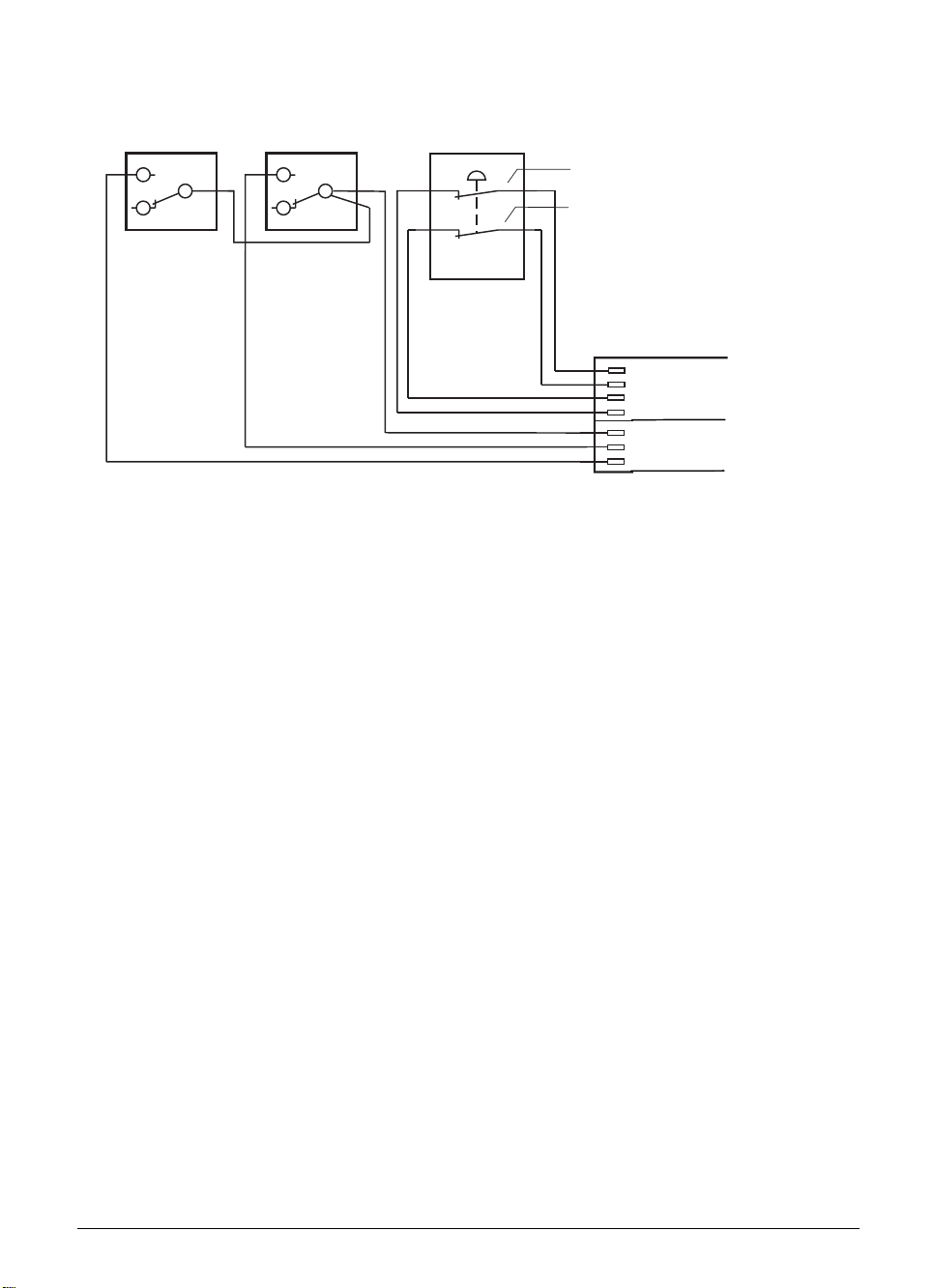
Internal wiring of the contacts for the HR 410 permissive buttons and the EMERGENCY STOP
button:
Permissive button 1 Permissive button 2 EMERGENCY STOP
Zustimmtaste 1
Zustimmtaste 2
1
1
NOT - AUS
2
2
Kontakt 2
Contact 2
Kontakt 1
Contact 1
Cable adapter
Kabeladapter
4
Kontakt 2
Contact 2
2
Contact 1 X2
Kontakt 1
1
Contact 1
Kontakt 1
3
Contact 2
Kontakt 2
3
Kontakt 1+2
Contact 1+2
2
Contact 2 X1
Kontakt 2
1
Contact 1
Kontakt 1
X2
X1
• When machine parameters are being downloaded via the V.24 interface, comments beginning
with the characters ";" or "*" can also be downloaded, either before or after the machine
parameter value.
• Machine parameter MP5020, bit 9 decides whether the control sends the EOT character after
receiving the ETX character.
• The error message "ERROR IN TRANSFERRED VALUE“ is displayed after a timeout is exceeded
during transfer via the V.24 interface.
• PLC Module 9036 expanded
With Module 9036, handwheel interpolation factors of all or of individual axes, and the values for
the jog positioning can be transferred from the PLC to the NC.
Calling the module:
PS B/W/D/K PLC status information type
PS B/W/D/K PLC status value
CM 9036
PL B/W/D Messages that are stored in the STACK:
0: PLC status information was transferred
1: Incorrect PLC status information type
2: Transferred PLC status value incorrect
3: Writing inhibited (e.g. by MP)
The marker M3171 is set if there is an error in transfer.
4/96 TNC 360 Update Information No. 8 1-3
Page 7

NC status information type: PLC status value:
0: Handwheel interpolation factor for X-axis 0 ... 10
1: Handwheel interpolation factor for Y-axis 0 ... 10
2: Handwheel interpolation factor for Z-axis 0 ... 10
3: Handwheel interpolation factor for 4th axis 0 ... 10
4: Handwheel interpolation factor for all axes 0 ... 10
5: Handwheel interpolation factor for all axes 0 ... 10
6: Select handwheel axis; X-axis 0
Y-axis 1
Z-axis 2
4th axis 3
7 to 9 reserved
10: Limit on jog increment 0 ... 50000 µm
-1 = Remove limit, activate last jog
increment
-2 = Remove limit, activate minimum from
PLC limit on jog increment and jog
increment input via NC
1-4 TNC 360 Update Information No. 8 4/96
Page 8

Update Information No. 7
The new edition of the Technical Manual for TNC 360 incorporates the data from Update Information
issues No. 1 to 6 in the appropriate chapters and sections. The description of TNC 355 has been
deleted since this unit is no longer in our product program.
Please replace the complete contents of the manual.
We will continue to send new information on the hardware and software of the TNC 360. Please file
the Update Information issues here.
8/95 TNC 360 Update Information No. 7 1-1
Page 9

Update Information No. 6
New PLC Input/Output Unit PL 410 B
In December the PLC I/O unit PL 410 will be replaced by the PL 410 B.
The PL 410 B provides the same number of switching inputs/output as on the PL 410.
The connector layout is compatible with the PL 410. The dimensions have changed slightly
near the connections X15 to X22.
In contrast to the PL 410, the PL 410 B will be available in two versions. The following version
can be connected to the TNC 360:
PL 410 B Id.-Nr. 263 371 12
64 PLC inputs
31 PLC outputs
1 output “Control is operational“
The logic unit must be connected to the PL 410 B with a new connecting cable.
Connecting cable LE 360C/ PL 410 B: Id.-Nr. 289 111 ..
Max. 20 m
10/94 TNC 360/TNC 335 Update Information No. 6 1-1
Page 10

Update Information No. 5
For NC software types 260 02 and 280 49, software version 13 was released in mid-June1994,
software version 14 at the end of June, and software version 15 at the beginning of July.
Software version 13 contains the following enhancements:
The input range for machine parameter MP1350 (type of reference mark approach) was
expanded. An input value of 3 selects encoders with distance-coded reference marks, and
thedirection of traverse reverses when the trip dog for the reference end position is crossed.
Data transfer in blockwise mode (ACK/NAK protocol) could be interrupted if the control
characters STX or ETB were transmitted incorrectly. Since the TNC did not know the cause of
the interruption, it sends NAK (after a delay in which no further data are transferred) if a block
was not completely recognized due to a faulty STX or ETB.
If ACK is not received within a certain time, the error message TRANSFERRED DATA
INCORRECT N is generated.
If bit 3 in machine parameter MP7641 is set, the electronic handwheel is selected in each
operating mode (initially before REF traversing) to be able to interrogate the inputs of the
handwheel keys (except axis keys) in the PLC. The axis keys on the handwheel and the
handwheel impulses do not become active until handwheel mode is selected. After an error the
handwheel is not selected again until the handwheel key is pressed.
If the operating voltage of the control is outside the limit values, the blinking error message
PROCESSOR CHECK ERROR M is displayed.
The input range of machine parameter MP4220 has been expanded to 0 ... 65535.
The memory for the executable PLC program has been increased from 28K bytes to 32K bytes.
The value for the analog voltage of the analog input at connector X8 is transferred to word
W392.
The meaning of machine parameter MP7225 (automatic block generation with the capture
actual position key or with PLC marker M2829) has been changed as follows:
MP7225 = 1 : Block generation with the capture actual position key
MP7225 = 2 : Block generation with PLC marker M2829
MP7225 = 0 : No block generation
The resolution of the feed rate display depends on the programmed feed rate:
Feed rate ≤ 31 999 mm/min (previously 29 999 mm/min): display step 2 mm/min
Feed rate > 31 999 mm/min (previously 29 999 mm/min): display step 20 mm/min
Software version 14 was released to correct the following error:
If a STOP and an M function for PLC positioning were executed in one NC block, in the
following block an M function that becomes effective at the beginning of the block (e.g., M3)
was not executed!
7/94 TNC 360/TNC 335 Update Information No. 5 1-1
Page 11

Software version 15 was released to correct the following error:
### If, in an OEM cycle that was run from the EPROM, the feed rate was defined via Q parameter,
a greatly excessive feed rate was ouput.
1-2 TNC 360/TNC 335 Update Information No. 5 7/94
Page 12

Update Information No. 4
In late February 1994, software version 12 was released for the NC software 260 02 and 280 49.
Note:
In software version 11, the deceleration ramp is too flat when the feed rate is changed at constant
contour transitions during operation with feed precontrol. This error was corrected in software
version 12.
Software version 11 must be replaced by software version 12!
No new features were introduce in software version 12.
2/94 TNC 360/TNC 335 Update Information No. 4 1-1
Page 13

Update Information No. 3
Software version 11 for software types 260 02 and 280 49 was released at the end of January 1994.
Software version 10 was not released for general distribution.
The following improvements were made since version 9:
Machine parameter 7411 defines whether during execution of the TOUCH-PROBE block the
•
current compensation values for probe length and radius should be taken from the central tool
file or from the calibration process.
MP7411 = 1 : Probe length and radius values from the tool file
MP7411 = 0 : Probe length and radius values from the calibration process
MP 7411 is also effective for tool length compensation in the digitizing cycles. This machine
parameter was already available in version 08, but it was not documented.
Machine parameter MP7225 was introduced for automatic generation of NC blocks in the
•
PROGRAMMING AND EDITING mode. With the "actual position capture" key (teach-in) it is now
possible to generate a positioning block in plain language dialog (not in ISO mode) with a
maximum of 3 axes and without feed rate, radius compensation or M-functions. This positioning
block is inserted below the currently addressed block in the selected NC part program. The
current actual position values become the nominal position values. The axis is selected in the
dialog "AXIS SELECTION =" in the MOD operating mode. Here up to 3 out of 4 axes can be
selected by pressing the corresponding axis keys.
MP7225 = 1 : Block generation with the actual-position-capture key (teach-in)
MP7225 = 2 : Block generation with the actual-position-capture key or with the PLC marker
M2829 (the marker is reset by the NC)
MP7225 = 0 : No block generation or axis selection possible.
If the machine parameters are erased, the RS-232-C/V.24 interface is now preset to FE mode.
•
PLC inputs I160 to I175 (HR 332 handwheel) now generate signal edges. The positive edge is
•
assigned to markers M1660 to M1675, the negative flank to markers M1860 to M1875.
If machine parameter MP7641, Bit 2 = 1, the interpolation factor for the handwheel can be set
•
both from the keyboard as well as from PLC module 9036. If Bit 2 = 0, the machine parameter
functions as before (input either from the keyboard or from PLC module 9036).
The NC saves the code number entered in the MOD mode in Doubleword D276.
•
Machine parameter MP810 defines the modulo value for reducing the position values of the
•
auxiliary axes. Machine parameter MP7470 has no effect on auxiliary axes. Rotary axes as NC
axes are always reduced to the range 0° to 359.999°. Machine parameter MP810 was already
available in version 08, but it was not documented.
1/94 TNC 360/TNC 335 Update information No. 3 1-1
Page 14

The new PLC module 9124 makes it possible to set a feed rate override value for secondary
•
axes. The override value can lie between 0% and 100% (resolution 0.01 %) and must be
transferred as a whole number (0 to 10 000). It can be set before the beginning of a movement
or during the movement of an auxiliary axis. If the control is reset, the NC presets an override
value of 100%.
Call :
PS B/W/D/K <Axis> (0..3 for X/Y/Z/4)
PS B/W/D/K <Override value> (0..10 000)
CM 9124
PL B/W/D <Error code>
0: Override was set
1: Invalid axis was entered
2: Axis is not defined as auxiliary axis
3: Override value is invalid
Error status after call: M3171 = 0 : Override was set
= 1 : Error condition see above
If more than one of the PLC modules 9120/9121/9123 for controlling the movement of auxiliary
axes is called within one PLC scan, only the last called PLC module is executed. The module
9124 can be called in addition to the above modules within one PLC scan, but it will always
become effective after the other module.
In PLC module 9036 (transferring PLC status information to the NC) the interpolation factor can
•
be set for all axes by transferring the value 4 or 5.
The PLC can inhibit the reference pulse for specific axes through Word W608 (bit-
•
coded,....4zyx).
Bit = 1 : Reference pulse is not evaluated
Bit = 0 : The next reference pulse is evaluated
By setting marker M2615 the reference mark of the spindle is evaluated again. The marker is
•
reset by the NC.
Marker 2510 fixes the spindle potentiometer setting at 100%. Marker M2511 has the same
•
effect on the feed rate potentiometer.
CC blocks in OEM cycles are effective only locally and are not transferred into the calling
•
program.
1-2 TNC 360/TNC 335 Update information No. 3 1/94
Page 15

Update Information No. 2
In earl September 1993 the software version 09 was released for the software types 260 02 and
280 49.
The new version contains the following changes:
If marker M2612 (Suppress position exchange in the tool table) is set before a T strobe is set
•
(M2046), the position numbers are not exchanged. The PLC acknowledges the T strobe without
having exchanged in the tool magazine and resets the PLC marker M2612. The new tool
number is shown inverted and the associated tool data (length and radius) are activated. The
tool number is shown inverted in the status display until the tool has physically been changed. If
the control is switched off and on in this condition, the last exchanged tool becomes active
again.
During execution of cycle 13 (spindle orientation) the NC sets the new marker M2408. This
•
marker can be evaluated by the PLC for the spindle orientation and should afterwards be reset
by the PLC.
9/93 TNC 360/TNC 335 Update information No. 2 1-1
Page 16

Update Information No. 1
1 Software
In July 1993 the following software was released:
260 02x 08 for insertion of 1M byte EPROMs
and 280 49x 08 for insertion of 2M byte EPROMs
The software numbers 280 49x 01 to 07 were not delivered. The new software version became
necessary because new logic units can also accommodate 2M byte EPROMs (see below in Section
2 "Hardware").
The new software version contains the following changes:
The PLC can limit the maximum feed rate through the doubleword D596. In order to ensure
•
compatibility to previous PLC programs the doubleword D596 is preset with the value
300 000 mm/min after control switch-on or after interruption of the PLC run.
The new feed rate is effective immediately!
The doubleword D596 has no effect with the new cycles "Tapping" (Cycle 2) and "Rigid Tapping"
(Cycle 17).
In the newly introduced machine parameter MP60, axes can be defined as auxiliary axes.
•
These axes cannot be moved by an NC program. They are controlled exclusively by the PLC.
All auxiliary axes work independently of each other. Auxiliary axes always move in trailing
mode. The following modules are available for the PLC to control the axes:
Module 9120: Positioning of auxiliary axes
Module 9121: Stopping the auxiliary axes
Module 9122: Status inquiry of auxiliary axes
Module 9123: Traversing the reference point of an auxiliary axes
Spindle orientation can be suppressed at the beginning of Cycle 17 "Rigid Tapping" with
•
machine parameter MP7160. At the beginning of the cycle, the spindle voltage is decelerated
with the ramp from MP3410.1 to the value 0 volts.
In this case it is not possible to cut into the same thread several times!
Up to 20 NC "tool def" blocks can be read-in during blockwise transfer without central tool
•
memory, whereby the tool def block must be read-in before the associated "tool call". When a
"PGM call" NC block is read-in or when a user cycle is called, the NC blocks with "tool def" are
considered up to the above mentioned limit and provided that the proper order is followed. A
violation of these preconditions releases the error message "TOO MANY TOOLS".
9/93 TNC 360/TNC 335 Update information No. 1 1-1
Page 17

If bit 2 is set in machine parameter MP7300, the last inserted (programmed) tool is
•
automatically activated during switch-on.
By setting the static PLC marker M2612 the PLC can now prevent the exchange of pocket
•
numbers in the central tool memory during a P output.
Function FN19 was introduced, with which two numerical or Q parameter values with an
•
accuracy of 1/1000 (i.e., three places after the decimal point) are transferred into the PLC
doublewords D280 and D284. A value of 2.5, for example, is filed in the doublewords as 2500.
The unit of measure of the calling NC program is set in marker M2150 (millimeter=0/inch=1).
During transfer the NC sets the strobe marker M2149. The transfer must be acknowledged by
the PLC with the marker M2611.
The number of PLC labels was increased to 1024.
•
Marker M2614 was introduced. Setting this marker blocks the output of PLC functions
•
(M/S/T/Q output) by the NC. The marker is set and reset by the PLC; it is read by the NC.
Marker M2827 was introduced. It is set by the PLC and causes the following behavior in case
•
of an external EMERGENCY STOP and erasable positioning error:
Machining is not aborted ("control in operation" symbol off, strobe signal reset). Instead,
machining is merely interrupted as in an NC STOP (control-in-operation symbol blinks). This
permits machining to be resumed with NC START after the error has been corrected. This
marker functions only for the output of M/S/T/Q strobes.
Now a maximum of 32 Q parameters can be transferred for user cycles. To do this, the 'DLG-
•
DEF' or 'DLG-CALL' blocks must be programmed several times in the user cycle, whereby in
the third DLG block only the first five entries can be evaluated.
The following Q parameters were introduced:
•
Q114 current tool length
Q115 to Q118 measured values of the 4th axis after a programmed probing cycle
The type of tool compensation (R0/RR/RL/R+/R-) is stored in Q parameter Q123:
•
Q123 = 0 means R0
= 1 means RR
= 2 means RL
= 3 means R+
= 4 means R-
Application as positioning module:
•
If machine parameter MP 4010 = 1 is programmed (PLC program from RAM), no machine
parameters will be taken from the PLC EPROM when the positioning module is switched on. If
the CRC sum of the machine parameters is incorrect they will be taken from the PLC EPROM.
1-2 TNC 360/TNC 335 Update information No. 1 9/93
Page 18

The software now supports PLC subprograms stored in the PLC-EPROM (translated PLC
•
code). With the PLC.EXE programming software from HEIDENHAIN such programs can be
written and on an external computer and filed in the PLC EPROM.
The incremental jog positioning can be activated or deactivated (dialog "JOG-INCREMENT: ...")
•
in the 'ELECTRONIC HANDWHEEL' operating mode by pressing the 'ELECTRONIC
HANDWHEEL' key, provided that marker M2498 is set.
In the 'PROGRAMMING AND EDITING' operating mode the electronic handwheel can be used
•
to move the axes, provided that in machine parameter MP7641 bit 1 = 1. The interpolation
factor (regardless of handwheel model) and the handwheel axis (for HR130) can be change
only in the 'ELECTRONIC HANDWHEEL' operating mode. A handwheel axis, once chosen,
remains in effect even when the operating mode is changed.
Simultaneous operation of the handwheel interface and the RS-232-C interface at differing
baud rates (38 400 and 19 200 baud) results in the error message "BAUD RATE NOT
POSSIBLE".
The current feed rate in mm/min is now available in the PLC.
•
Module 9150
•
During an active M/S/T output the PLC can use module 9150 to define an NC block, which is
then executed after the M/S/T strobe is acknowledged, before the control continues the NC
program. An NC block can also be defined if no program is being run. The block is then
executed immediately.
Call:
PS B/W/D/K <Instruction code>
PS B/W/D/K <Address of the parameter block in the B/W/D range>
CM 9150
PL B/W/D <Error code>
Error code: 0 = NC block was inserted
1 = NC program started, but no M/S/T strobe
2 = Unknown instruction code
3 = Incorrect address in B/W/D range
Error status after call: M3171 = 0 NC block was inserted
= 1 error condition see above
At present the instruction code <0> is implemented for TOOL CALL
Parameters :
B<Adr+0> active elements bit-coded
Bit 0 =1: Tool number, otherwise modal
Bit 1 =1: Tool axis, otherwise modal
Bit 2 =1: Spindle speed, otherwise modal
Bit 3 =0
Bit 4 =0
B<Adr+1> Tool axis (0/1/2/3 = X/Y/Z/IV)
W<Adr+2> Tool number
D <Adr+ 4> Spindle speed (Format 0.001 rpm)
9/93 TNC 360/TNC 335 Update information No. 1 1-3
Page 19

Module 9120
•
Positioning an auxiliary axis
The positioning of an axis is started by presetting a target position (in the reference system), a
feed rate and a flag register. The axis is positioned without regard to other processes in the
control. There is no contour interpolation with other axes.
Conditions:
The given axis must be activated via MP10 and configured as an auxiliary axis via MP60.
The values for rapid traverse, analog voltage for rapid traverse, acceleration, etc., must be
properly set in the machine parameters.
For axes with automatic reduction (modulo value in MP810.x) the axis is always moved in the
shortest direction to the target position, unless the target position is entered as an incremental
value.
There is no checking for violations of the limit switch ranges!
The axis must be stationary. If the axis is already moving, the positioning must be terminated
beforehand with module 9121.
If the axis was in the reference point traversing mode, this state is canceled. The positioning
always builds on the momentary counter contents.
If the modules 9120, 9121 and 9122 are called several times during a PLC scan, only the last
instruction is executed.
If a "positioning error" status was set in this axis it is erased.
Potential errors:
A non-existent axis was transferred.
An axis was transferred that was not identified as an auxiliary axis in MP10 and MP60.
The axis is already moving.
Call:
PS B/W/D/K <Axis> (0 to 3 for X/Y/Z/4)
PS B/W/D/K <Target position> (in the reference system, Format 0.001mm)
PS B/W/D/K <Feed rate> (mm/min)
PS B/W/D/K <Flag register> Bit 0 = 1: incremental target position
= 0: absolute target position
CM9120
PL B/W/D <Error code>
0: Positioning was started
1: A non-existent axis was transferred
2: Axis is not configured as an auxiliary axis
3: The axis is already moving
4: Absolute position outside of the modulo range
Error status after call: M3171 = 0: Positioning was started correctly
= 1: Positioning was faulty
1-4 TNC 360/TNC 335 Update information No. 1 9/93
Page 20

PLC MODULE 9121
•
Stopping a positioning with an auxiliary axis
A positioning started beforehand with modules 9120 or 9123 can be canceled at any time with
module 9121.
Conditions:
The given axis must be activated via MP10 and configured in MP60 as an auxiliary axis.
If modules 9120, 9121 and 9122 are called several times for the same axis during a PLC-scan,
only the last instruction will be executed.
Potential errors:
A non-existent axis was transferred.
An axis was transferred that was not configured in MP10 and MP60 as an auxiliary axis.
The given axis is already stationary.
Call:
PS B/W/D/K <Axis> (0 to 3 for X/Y/Z/4)
CM9121
PL B/W/D <Error code>
0: Positioning is canceled
1: A non-existent axis was transferred
2: Axis is not configured as an auxiliary axis
3: Axis was already stationary
Error status after call: M3171 = 0: Positioning was stopped
= 1: Faulty execution
PLC MODULE 9122
•
Inquiring the status of an auxiliary axis
For a certain axis a bit-coded status word is transferred that contains information on the
momentary operating state of this axis.
Conditions:
Status changes causes by commands that the PLC sends to control the auxiliary axes
(modules 9120, 9121, 9123) are not recognized until the next PLC scan.
After switch-on, bit 1 (axis over reference point) is erased.
It is possible to position the axis without traversing the reference point first.
9/93 TNC 360/TNC 335 Update information No. 1 1-5
Page 21

Potential errors:
A non-existent axis was transferred.
Call:
PS B/W/D/K <Axis> (0 to 3 for X/Y/Z/4)
CM9122
PL B/W/D <Status>
Bit 0: 1= Axis is auxiliary axis
Bit 1: 1= Axis has traversed the reference point
Bit 2: 1= Axis is positioned
Bit 3: 1= Direction of motion is negative
Bit 4: 1= A positioning error has occurred
Error status after call: M3171 = 0: Status was transferred
= 1: Faulty execution
PLC MODULE 9123
•
Passing over the reference point of an auxiliary axis
The module starts positioning in a preset direction, which continues until a reference point is
found or the positioning is canceled with module 9121.
Conditions:
The given axis must be activated via MP10 and configured as an auxiliary axis via MP60.
The values for rapid traverse, analog voltage for rapid traverse, acceleration, etc., must be set
in the machine parameters.
There is no checking for violations of the limit switch ranges!
The axis must be stationary. If the axis is already moving, the positioning must be canceled
beforehand with module 9121.
The feed rate override is not included in the calculation.
The state "reference point not yet traversed" is set for the axis.
A reference point that already exists in this axis is erased, but not the numerical value of the
axis. This is not reinitialized until the reference point is found.
If modules 9120, 9121 and 9122 are called several times during a PLC scan, only the last
instruction is executed.
If a "positioning error" status was set in this axis it is erased.
The positioning is stopped as soon as the reference point is reached. Since the axis must
decelerate before it can stop, it comes to rest behind the reference point in the direction of
motion.
1-6 TNC 360/TNC 335 Update information No. 1 9/93
Page 22

Potential errors:
A non-existent axis was transferred.
An axis was transferred that was not configured in MP10 and MP60 as an auxiliary axis.
The axis is already moving.
Call:
PS B/W/D/K <Axis> (0 to 3 for X/Y/Z/4)
PS B/W/D/K <Feed rate> (mm/min)
PS B/W/D/K <Flag register> Bit 0 = 1: negative traverse direction
= 0: positive traverse direction
CM9123
PL B/W/D <Error code>
0: Positioning was started
1: A non-existent axis was transferred
2: The axis is not configured as an auxiliary axis
3: The axis is already moving
Error status after call: M3171 = 0: Positioning was started
= 1: Faulty execution
2 Hardware
The part numbers of the LE 360C logic units that can accommodate 2M byte EPROMs are:
Id.-Nr. 270 641 3x for BE 212
Id.-Nr. 270 642 3x for BF 110
The 2-M byte EPROMs occupy only the sockets IC-P1 and IC-P2. IC-P3 and IC-P4 remain vacant.
The jumper located next to IC-P1 should then be inserted in the setting 2M!
You will receive Update Information issues on the TNC 360/TNC 335 hardware and software
whenever developments warrant. This information will then be included in Supplementary Issues
that you can integrate into the appropriate chapters of the Technical Manual.
9/93 TNC 360/TNC 335 Update information No. 1 1-7
Page 23

Introduction – Contents 2
1 Hardware Concept 2-2
2 Features and Specifications 2-3
2.1 TNC 360 2-3
3 Software 2-6
3.1 NC Software 2-6
3.1.1 Software and hardware versions 2-7
3.1.2 Software option 2-8
3.2 PLC Software 2-8
3.3 EPROM sockets 2-9
8/95 TNC 360 2-1
Page 24
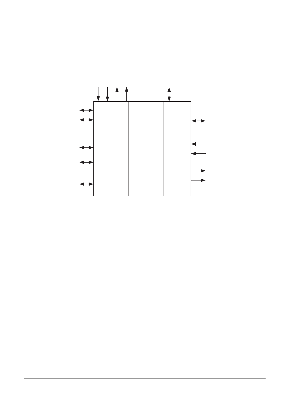
1 Hardware Concept
The HEIDENHAIN TNC 360 contouring control is designed for use with drilling and milling machines.
The HEIDENHAIN TNCs consist of several units. The principle subassembly is the logic unit. The
logic unit is joined to the other units and the TNC accessories by connecting cables.
Noml. value outputs
Encoders
• • •• • •
Visual display unit
TNC keyboard unit
PLC I/0 unit
Machine operating panel
Touch probe
Electronic handwheel
Data interfaces
NC
Common
data area
PLC
PLC inputs
• • •• • •
PLC outputs
The logic unit contains the electronics for both the NC and the PLC sections of the control.
The common data area contains the machine parameters and the PLC markers and words. The
machine parameters define the hardware-configuration of the machine (ranges of travel,
acceleration, number of axes etc.). The PLC markers and words are used for the exchange of
information between the NC and the PLC.
2-2 TNC 360 1 Hardware Concept 8/95
Page 25

2 Features and Specifications
2.1 TNC 360
Components • Logic unit LE 360
• Keyboard TE 355 A, TE 355 B
• Color graphics VDU BE 212 (12 inch, 512 x 256 pixels)
• Flat luminescent screen BF 110 (192 mm x 120 mm, 640 x 400 pixels)
Control modes • Contouring control for 4 axes and spindle orientation
• Linear interpolation in 3 of 4 axes
• Circular interpolation in 2 of 4 axes
Program memory Buffered RAM memory (approx. 70 KB) for 32 NC programs,
central tool file, PLC program (if not filed in EPROM),
EPROM memory (128 KB) for PLC program, OEM cycles,
dialogues for OEM cycles, PLC error messages
Tool memory 99 tools
Operating modes • Manual operation
• Electronic handwheel /jog positioning
• Positioning by manual data input
• Program run, single block
• Program run, full sequence
• Programming and editing
• Test run (logical and graphical)
Programming In HEIDENHAIN conversational mode and according to ISO
Entry and display 1 µm, 5 µm, 10 µm, 50 µm, 100 µm
resolution
8/95 TNC 360 2 Features and Specifications 2-3
Page 26
Programmable • Nominal position (absolute or incremental dimensions) in Cartesian or
functions polar coordinates
• Straight lines
• Circular arcs
• Helical interpolation
• Corner rounding, chamfering
• Tangential approach and departure from a contour
• Tool number, tool length and radius compensation
• Spindle speed
• Rapid traverse
• Feed-rate
• Program call from inside other programs
• Subprograms and repetition of program sections
• Fixed cycles for peck drilling, tapping (without floating tap holder),
slot milling, rectangular pocket milling, circular pocket milling
• Cycles for milling pockets with a free contour (SL cycles)
• Shifting and rotation of the coordinate system, mirroring, scaling,
dwell time, miscellaneous functions M, program stop
• Spindle orientation (to be implemented by the machine manufacturer)
• OEM specific cycles (to be defined by the manufacturer of the machine)
Parameter- Mathematical functions (=, +, −, x, :, sin, cos, angle α of r sin α and
programming r cos α,
, a² + b²), parameter comparison (=, ≠, >, <),
output of parameter values via the data interface
Digitizing • With TS 120 and TNC software expansion option
• Optional evaluation software for PCs
Maximum traverse ± 30 000 mm (1181 in.)
Maximum 300 m/min (11 810 ipm)
traversing speed
Data interfaces • RS-232-C/V.24; data transfer rates up to 38 400 baud
Cycle times Block processing time: 40 ms (for 3D straight lines without radius com-
pensation and with 100% PLC utilization)
Control loop cycle time: 6 ms
PLC cycle time: 24 ms
Position feedback Incremental HEIDENHAIN linear and angular encoders, preferably with
distance-coded reference marks, or incremental HEIDENHAIN rotary
encoders
2-4 TNC 360 2 Features and Specifications 8/95
Page 27

Control • 4 inputs for position measuring systems (4 sinusoidal inputs)
inputs • 1 measuring system input for spindle orientation (square-wave input
signal)
• 1 input for electronic handwheel
• 1 input for 3D-touch probe system
• 55 PLC inputs + 1 control-is-ready input
• Additionally 64 PLC inputs on optional PLC I/O board PL 410 B
Control • 5 analogue outputs for the spindle and axes
outputs • 31 PLC outputs + 1 control-is-ready output
• Additionally 31 PLC outputs on optional PLC I/O board PL 410 B
Integrated PLC • Programming in the form of a list of instructions, max. 4000 PLC
commands
• Entry by HEIDENHAIN keyboard or data interface
Supply NC: 24 Vdc (See Chapter 3, Section 4.1)
voltage PLC: 24 Vdc
Power NC: approx. 27 W (with BE 212 connected)
consumption PLC: approx. 48 W (See Chapter 3, Section 4.1)
PL 410 B: approx. 480 W (See Chapter 3, Section 4.1)
BF 110: approx. 33 W
Environmental • Operating: LE/BE 0 to 45° C (32 to 113° F)
temperature BF 110: 0 to 40° C (32 to 104° F)
• Storage: –30 to 70° C (–22 to 158° F)
Approximate LE 360 C: 8.0 kg
weight TE 355: 1.6 kg
BE 212: 11.0 kg
BF 110: 1.7 kg
PL 410 B: 1.5 kg
HRA 110: 0.7 kg
8/95 TNC 360 2 Features and Specifications 2-5
Page 28
3 Software
The logic unit contains separate software for the NC section and the PLC section. The software is
identified by an 8-digit number.
After switching on the control, the NC and PLC software numbers are displayed on the screen. The
software number can also be directly requested with the aid of the MOD function.
3.1 NC Software
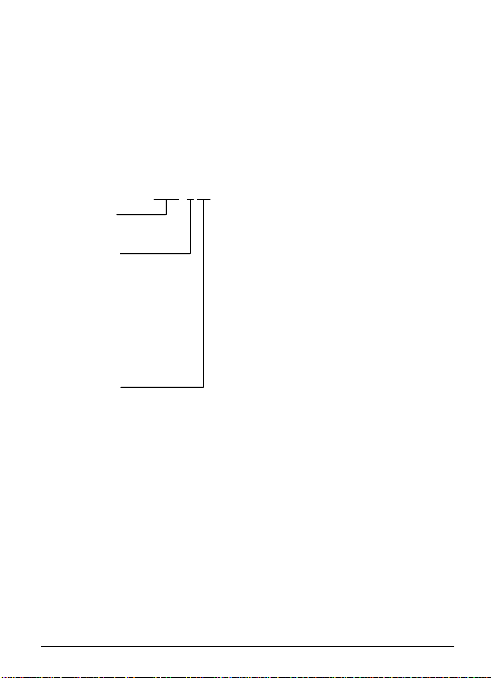
The 8-digit NC software number identifies the type of software, the dialogue language (language of
the country) and the software version.
260 02 0 15
Software-Typ
Software type
Landessprache
National language
0 = deutsch
0 = German
1 = tschechisch
1 = Czech
2 = französisch
2 = French
3 = italienisch
3 = Italian
4 = spanisch
4 = Spanish
5 = portugiesisch
6 = Swedish
6 = schwedisch
7 = Danish
7 = dänisch
8 = Finnish
8 = finnisch
9 = niederländisch
9 = Dutch
Software version
Software-Version
In addition to the above-listed languages, the TNC can always display English, which may be
selected via the machine parameter MP7230.
2-6 TNC 360 3 Software 8/95
Page 29

3.1.1. Software and hardware versions
HEIDENHAIN has manufactured several different hardware versions of the logic units LE 360 and LE
360 C. The following table shows which software is compatible with which hardware version:
Id.-Nr. LE 360 Id.-Nr. LE 360 C
Software Type
/Version
259 90x 02 to 05 02 to 05 02 to 05 06 260 02x (1-MB
EPROM)
280 49x (2-MB
EPROM)
Only the software types 260 02 and 280 49 will continue to be developed.
Software Releases
HEIDENHAIN releases new versions of NC software in irregular intervals.
NC Software Version Release
259 90x 02 1/91 (Introduction)
259 90x 03 7/91
259 90x 04 3/92
259 90x 05 3/92
259 90x 06 7/92
258 991 99 264 660 99 264 085 99 270 641 39
(BE 212)
- - from 07 from 07 from 07
- - - from 08 from 08
270 642 39
(BF 110)
260 02x 04 3/92 (Introduction)
260 02x 05 3/92
260 02x 06 7/92
260 02x 07 10/92
260 02x 08 7/93
260 02x 09 9/93
260 02x 10 Never released
260 02x 11 1/94
260 02x 12 2/94
260 02x 13 6/94
260 02x 14 6/94
260 02x 15 7/94
260 02x 16 3/95
280 49x 08 7/93 (Introduction)
280 49x 09 9/93
280 49x 10 Never released
280 49x 11 1/94
280 49x 12 2/94
280 49x 13 6/94
280 49x 14 6/94
280 49x 15 7/94
280 49x 16 3/95
8/95 TNC 360 3 Software 2-7
Page 30

3.1.2 Software option
HEIDENHAIN offers the "Digitizing with TS 120" function as a software option (see Chapter "Machine
integration"). An additional software protection module is installed in controls supplied with this
software option. The Id.-Nr. of the LE 360 logic unit has the variant xxx xxx 79, while the LE 360 has
xxx xxx 34. If the software module is installed, the option number 262 351 01 is indicated on the
screen under the NC and PLC software numbers.
The “Digitizing with TS 120“ software option can be retrofitted. The kit is available under Id. Nr.
265 310 01.
The kit contains:
Software module (EPROM Id.-Nr. 262 351 01)
Printed circuit board
Sponge rubber
ID label
Mounting Instructions
3.2 PLC Software
The PLC software is produced by the manufacturer of the machine. Either HEIDENHAIN or the
manufacturer of the machine can store this software in EPROMs. HEIDENHAIN assigns PLC
software numbers to the machine manufacturers on request. HEIDENHAIN can archive the specific
PLC programs in a data bank, so that the installation of the correct PLC program is assured if a
control has to be exchanged.
2-8 TNC 360 3 Software 8/95
Page 31

3.3 EPROM sockets
Sockets for the processor board:
]
Modul
SW
IC-P3
IC-P4
IC-P1
IC-P2
IC-S [
IC-P5 [PLC-EPROM]
If the 2-MB EPROMs are used, only the sockets IC-P1 and IC-P2 are needed. IC-P3 and IC-P4
remain vacant. The jumper located next to IC-P1 must then be set to position 2M.
8/95 TNC 360 3 Software 2-9
Page 32

Mounting and Electrical Installation – Contents
1 Hardware components TNC 360 3-4
1.1 Changes in the ID-number 3-6
2 Assembly Hints 3-8
2.1 Electrical noise immunity 3-8
2.2 Heat generation and cooling 3-8
2.3 Humidity 3-9
2.4 Mechanical vibration 3-9
2.5 Mounting position 3-9
2.5.1 Logic unit 3-10
2.5.2 Visual display unit (VDU) 3-11
2.5.3 PLC Input/Output board PL 410 3-11
2.6 Degree of protection 3-11
3 Summary of Connections 3-12
4 Power Supply 3-14
4.1 Overview 3-14
4.1.1 NC power supply 3-14
4.1.2 PLC power supply 3-15
4.1.3 Buffer battery 3-16
4.2 Power supply for the visual display unit 3-17
5 Encoders 3-19
5.1 Linear encoders 3-19
5.2 Angular encoders 3-19
5.3 Encoder inputs for sinusoidal signals (7 to 16 mApp) 3-20
5.3.1 Connector assignments 3-20
5.3.2 Connecting cable 3-20
5.4 Encoder inputs for square-wave signals 3-21
5.4.1 Connector assignments 3-21
5.4.2 Connecting cable 3-21
6 Nominal Value Output 3-23
6.1 Connector assignment 3-23
6.2 Connecting cable 3-23
7 Visual Display Unit (VDU) 3-26
7.1 Connector assignment 3-26
7.2 Connecting cable 3-27
8/95 TNC 360 3-1
Page 33

8 Touch Probe System Input 3-28
8.1 Connector assignment 3-28
8.2 Connection of the touch probe system 3-29
8.2.1 TS 120 3-29
8.2.2 TS 511 3-30
9 RS-232-C/V.24 Data Interface 3-32
10 Handwheel Input 3-33
10.1 Pin layout 3-33
10.2 Portable handwheel HR 330 3-33
10.3 Integral handwheel HR 130 3-34
10.4 Portable handwheel HR 332 3-35
10.5 HRA 110 handwheel adapter 3-37
11 PLC inputs/outputs 3-40
11.1 Technical data 3-40
11.2 Connector assignment 3-41
11.2.1 PLC inputs 3-41
11.2.2 PLC output 3-42
11.3 Connecting cable 3-43
11.4 PLC I/O expansion-board 3-45
11.4.1 PL 400 connection 3-45
11.4.2 PLC inputs/outputs on the PL 400 3-47
11.5 PL 410 PLC I/O expansion-board 3-49
11.5.1 PLC inputs/PLC outputs on the PL 410 3-50
12 Machine control panel 3-53
12.1 Pin layout 3-53
12.2 Connecting cable 3-54
13 TNC keyboard 3-56
13.1 Pin connections 3-56
13.2 Connecting cable 3-57
14 Dimensions 3-58
14.1 LE 360 C 3-58
14.2 Keyboard units 3-59
14.2.1 TE 355 A 3-59
14.2.2 TE 355 B 3-60
14.3 Visual display units 3-61
14.3.1 BE 212 3-61
14.3.2 BF 110 3-62
3-2 TNC 360 8/95
Page 34

14.4 Input/Output units 3-63
14.4.1 PL 410 B 3-63
14.4.2 PL 410 3-64
14.4.3 PL 400 3-65
14.5 Panel-mounted handwheels 3-66
14.5.1 HR 130 3-66
14.5.2 HR 150 3-67
14.5.3 HRA 110 handwheel adapter (for HR 150) 3-68
14.5.4 Handwheel knobs 3-69
14.6 Cable adapter 3-72
15 Grounding Diagram 3-75
16 Cable Overview 3-77
8/95 TNC 360 3-3
Page 35

1 Hardware Components TNC 360
The TNC 360 consists of the following hardware components:
– LE 360 C (Logic unit),
– TE 355 A or TE 355 B (TNC keyboard),
– BE 212 or BF 110 (Visual display unit),
– if desired, PL 410 B
The TNC 360 is not subject to export restrictions. An export version is not necessary.
Logic unit
TNC 360 and TNC 335:
LE 360 C
Id.-Nr. 270 641 .. (for connecting the BE 212)
Id.-Nr. 270 642 .. (for connecting the BF 110)
TNC keyboard
TNC 360: TE 355 A (Id.-Nr. 255 015 01) TE 355 B (Id.-Nr. 255 016 01)
3-4 TNC 360 1 Hardware Components TNC 360 8/95
Page 36

Visual display unit
BE 212 (Id.-Nr. 242 370 01) BF 110 (Id.-Nr. 267 209 01)
PLC Input/Output Unit (Option)
PL 410 (Id.-Nr. 263 371 01)
8/95 TNC 360 1 Hardware Components TNC 360 3-5
Page 37

1.1 Changes in the ID Number
LE 360 Logic Unit:
Id.-Nr. 258 991 99 Series introduction since 1990
Id.-Nr. 258 991 98 Socket for "digitizing" software module since 1991
Id.-Nr. 258 991 79 Same as Id.-Nr. 258 991 98, but with software module since 1991
Id.-Nr. 264 660 99 New processor board since 3/91
Id.-Nr. 264 660 79 Same as Id.-Nr. 264 660 99 but with software module since 7/91
Id.-Nr. 264 085 99 New PLC- and graphics board since 7/91
Id.-Nr. 264 085 79 Like Id.-Nr. 264 085 99, but with software module since 7/91
LE 360 C Logic Unit
Id.-Nr. 270 641 29 For connecting a BE 212 since 1992
Id.-Nr. 270 641 24 With digitizing software module
Id.-Nr. 270 642 29 For connecting a BF 110 since 1992
Id.-Nr. 270 642 24 With digitizing software module
3-6 TNC 360 1 Hardware Components TNC 360 8/95
Page 38

2 Assembly Hints
2.1 Electrical noise immunity
Please note that the vulnerability of electronic equipment to noise increases with faster signal
processing and higher sensitivity. Please protect your equipment by observing the following rules
and recommendations.
Noise voltages are mainly produced and transmitted by capacitive and inductive coupling. Electrical
noise can be picked up by the inputs and outputs to the equipment, and the cabling.
Likely sources of interference are:
– Strong magnetic fields from transformers and electric motors,
– Relays, contactors and solenoid valves,
– High-frequency equipment, pulse equipment and stray magnetic fields from switch-mode
power supplies,
– Mains leads and leads to the above equipment.
Electrical interference can be avoided by:
– A minimum distance between the logic unit (and its leads) and interfering equipment > 20 cm.
– A minimum distance between the logic unit (and its leads) and cables carrying interference
signals > 10 cm.
(Where signal cables and cables which carry interference signals are laid together in metallic
ducting, adequate decoupling can be achieved by using a grounded separation screen)
– Screening according to DIN VDE 0160.
– Potential compensating lines ∅ ≥ 6 mm² (see Grounding diagram).
– Use of original HEIDENHAIN cables, connectors and couplings.
2.2 Heat generation and cooling
Please note that the reliability of electronic equipment is greatly reduced by continuous operation at
elevated temperatures. Please take the necessary measures to keep the unit within the permissible
ambient temperature range.
Permissible ambient temperature in operation: 0° C to 45° C (BF 110: 0° C to 40° C)
The following means may be employed to ensure adequate heat removal:
– Provide sufficient space for air circulation.
– Build in a ventilator fan to circulate the air inside the control cabinet. The fan must reinforce the
natural convection. It must be mounted so that the warm air is extracted from the logic unit
and no pre-warmed air is blown into the unit. The warmed-up air should flow over surfaces
which have good thermal conductivity to the external surroundings (e.g. sheet metal).
– For a closed steel housing without assisted cooling, the figure for heat conduction is 3 Watt/m²
of surface per °C air temperature difference between inside and outside.
– Use of a heat exchanger with separate internal and external circulation.
– Cooling by blowing external air through the control cabinet to replace the internal air. In this
case the ventilator fan must be mounted so that the warm air is extracted from the control
cabinet and only filtered air can be drawn in. HEIDENHAIN advises against this method of
cooling, since the function and reliability of electronic assemblies are adversely affected by
contaminated air (fine dust, vapors etc.). In addition to these disadvantages, a filter which is
not adequately serviced leads to a loss in cooling efficiency. Regular servicing is therefore
absolutely vital.
3-8 TNC 360 2 Assembly Hints 8/95
Page 39

Incorrect
LE
Obstructive
elements
Heat generating
elements
Correct
LE
2.3 Humidity
Permissible humidity: < 75 % in continuous operation,
< 95 % for not more than 30 days p.a. (randomly distributed).
In tropical areas it is recommended that the TNC is not switched off, so that condensation is avoided
on the circuit boards. The heat generation prevents condensation and has no further disadvantages.
2.4 Mechanical vibration
Permissible vibration: < 0.5 g
2.5 Mounting position
Note the following fundamental points on mounting:
– Mechanical accessibility
– Permissible environmental conditions
– Electrical noise immunity
– The electrical regulations in effect in your country
8/95 TNC 360 2 Assembly Hints 3-9
Page 40

2.5.1 Logic unit
HEIDENHAIN recommends the following mounting position:
>577
>110
Minimum clearance
for servicing!
recommended:=
approx. 250 mm
Maintain clearance
for screwdriver
Connecting cables
must not hinder
swivel movement
of the control
132.5
83
40
**
218.5
°C
30
60
40
80
80
40
°C
Air
**
outlet
°C
**
°C
100
30
**
160
°C
**
Air
inlet
°C
°C
**
Measuring point for
**
ambient temperature
Free space for air circulation
Free space for servicing
30
100
PL
°C
**
40
40°
40
3-10 TNC 360 2 Assembly Hints 8/95
R 325
270
Illustration of
max. swivel range.
The minimum angle of
swivel for exchange
of subassembly should
be at least 90°.
145
Page 41

2.5.2 Visual display unit (VDU)
Permissible ambient temperature
BE 212 max. 45° C (113° F)
BF 110 max. 40° C (104° F)
The VDU must be installed with a minimum clearance of 25 mm to the housing. It is recommended
especially, that a large area is left free above the unit for heat removal.
Temperature is measured at a distance of 25 mm to the housing. The above mentioned
temperatures must not be exceeded.
Please also note for the BE 212:
When mounting the VDU it must be remembered that this unit is very sensitive to magnetic pick-up.
The picture position and geometry can be disturbed by stray magnetic fields. Alternating fields cause
periodic movement or distortion of the picture.
For this reason, keep a minimum distance of 0.5 m between the VDU casing and the source of any
disturbance (e.g. permanent magnets, motors, transformers etc.)
2.5.3 PLC Input/Output board PL 410
One PL 410 can be connected to the LE 360 C, if desired. There is no preferred mounting position
for heat removal.
2.6 Degree of protection
When mounted, the visual display unit and the keyboard unit provide class IP54 protection against
dust and splashwater.
8/95 TNC 360 2 Assembly Hints 3-11
Page 42

3 Summary of Connections
Control loop board
24V
X31
X1
X2
X3
X4
X6
X11
X12
X8
X9
X21
X22
X23 X27
B
X24
X25
X26
X1 = Measuring system 1 (~)
X2 = Measuring system 2 (~)
X3 = Measuring system 3 (~)
X4 = Measuring system 4 (~)
X5 = Measuring system 5 (~)
X6 =
Measuring system S (
X12 = Touch probe system
X8 = Nominal value outputs 1,2,3,4,S
X9 = VDU
X11 = HR 130/330/332 handwheels,
HRA 110
PLC and graphics board
X21 = PLC output
X22 = PLC input
X23 = TNC keyboard (TE)
X24 = Power supply 24 V for PLC
X25 = Data interface RS-232-C/V.24
X26 = Input/Output board PL 410
X27 = Machine operating panel
X31 = Power supply 24 V for NC
B = Signal ground
)
Danger to internal components!
Do not engage or disengage any connections while the unit is under power.
3-12 TNC 360 3 Summary of Connections 8/95
Page 43

4 Power Supply
4.1 Overview
The supply voltages must meet the following specifications:
Unit Supply voltage Voltage range dc
average
LE NC 24 Vdc
(VDE 0160, 5.88
Lower limit
20.4 V
- - -
low-voltage
electrical
separation)
Upper limit
PLC 24 Vdc
31 V
- - -
1)
(VDE 0160, 5.88
base insulation)
PL 410 B
PL 410
PL 400
4
)
4
)
HRA 110 (VDE 0160, 5.88
low-voltage
electrical
separation)
BF 110
1
) Voltage surges up to 36 V
2)
permissible for t< 100 ms.
- - -
Max. current
consumption
Power
consumption
LE 360 1.5 A 28.8 ... 36 W
(also supplies
the BE 212)
2 A
when half
3
) of
the outputs are
switched on
simultaneously
20 A
3
when half
) of
the outputs are
switched on
simultaneously
Approx. 48 W
when half
3
) of
the outputs are
switched on
simultaneously
Approx. 480 W
when half
3
) of
the outputs are
switched on
simultaneously
0.2 A Approx. 5 W
Approx. 1 A with
full display
24 W typical
32 W max.
2
) The BF 110 has its own line power connection, which also powers the internal ventilation.
3
) No more than half the outputs can be switched on simultaneously.
4
) No longer included in product program
4.1.1 NC power supply
Connection terminal X31
Pin Number Assignment
1 + 24 Vdc
20 V
3-14 TNC 360 4 Power Supply 8/95
Page 44

The NC and the HRA 110 must not be supplied
from the machine control voltage supply! It
requires an individual, external and separately
generated supply voltage according to VDE
0551. Use 24 Vdc with a permissible ac
component of 1.5 Vpp (recommended filter
capacitor 10 000 µF/40 Vdc).
Danger to internal components!
The internal fuses of the power supply assembly must be exchanged only by
HEIDENHAIN personnel.
If the operating voltage of the control (5V on the processor board) is outside the limit values a
blinking error message "PROCESSOR CHECK ERROR M" is displayed.
24 V
U
1.5 V
pp
t
4.1.2 PLC power supply
The PLC section (PLC inputs and outputs) of the LE and PL is run from the 24 V machine control voltage
supply, generated according to VDE 0160.
Superimposed ac components, such as those caused by a three-phase bridge rectifier without smoothing,
are permissible up to a ripple factor of 5% (see DIN 40110/10.75, Section 1.2). This means an absolute
upper voltage limit of 32.6 V and an absolute lower voltage limit of 18.5 V.
U
32.6 V
31 V
20.4 V
18.5 V
t
8/95 TNC 360 4 Power Supply 3-15
Page 45

X24 power supply for the PLC at the LE
Pin Number Assignment
1 + 24 Vdc switched off by EMERGENCY STOP
2 + 24 Vdc not switched off by EMERGENCY STOP
30 V
Danger to internal components!
Use only original replacement fuses.
Power supply for the PL 410 B
The PLC outputs are powered in groups.
Terminal Assignment PLC output
X9 0V
X10 +24 V power for logic and for "Control is operational"
X11 +24 V power for outputs O32 to O39
X12 O40 to O47
X13 O48 to O55
X14 O56 to O62
Power supply for the PL 410
Connections as with PL 410 B.
Terminal Assignment
X13 +24 Vdc switched off by EMERGENCY STOP
X12 0 V
X3 Pin 12 + 24 Vdc not switched off by EMERGENCY STOP
4.1.3 Buffer battery
The buffer battery is the potential source for the RAM memory for NC programs, PLC programs
and machine parameters when the control is switched off.
If the ”EXCHANGE BUFFER BATTERY” message appears, the batteries must be exchanged.
The 3 batteries may be found behind a screw cap in the power supply section of the logic unit.
As well as the batteries, the logic unit contains an additional energy store, mounted on the
processor board, for buffering the memory contents.
This means that the mains can be switched off when replacing the batteries. The energy
store will ensure that the memory is retained while the batteries are exchanged.
3-16 TNC 360 4 Power Supply 8/95
Page 46

Type of batteries:
Three AA-size batteries, leak-proof,
IEC designation "LR6"
4.2 Power supply for the visual display unit
BE 212
The BE 212 visual display unit is powered through the LE (connector X9).
BF 110
X1 power supply
Pin Number Assignment
1 + 24 V
20 V
The BF 110 must not be supplied with 220 V!
8/95 TNC 360 4 Power Supply 3-17
Page 47

5 Encoders
The HEIDENHAIN contouring controls are designed for the installation of incremental linear and
angular encoders.
The control controls the actual position with a measuring step of 0.001 mm or 0.001°. Encoders with
a graduation period of 0.001 mm or 0.001° to 1 mm or 1° may be used.
It does not matter whether the encoder or encoder has one or several reference marks.
However, HEIDENHAIN recommends the use of encoders with distance-coded reference marks,
since the traversing distance when homing on the reference marks is thereby reduced to a
minimum. See chapter "Machine Integration."
5.1 Linear encoders
Measurement of length is best performed by a linear encoder. Insofar as it is compatible with the
accuracy requirements, linear measurement can also be made using a rotary encoder on the
ballscrew.
HEIDENHAIN recommends use of the following linear encoders:
LS 103 C, LS 106 C, LS 405 C, LS 406 C, LS 706 C, LB 326, ULS 300 C.
For linear measurement with the aid of a rotary encoder and a ballscrew you could use, for example,
an ROD 450.
5.2 Angle encoders
For direct angular measurement in the A, B or C axes the following incremental angle encoders are
available: ROD 250 C, ROD 700 C, RON 255 C, and RON 705 C.
In order to meet accuracy requirements, HEIDENHAIN recommends line counts of at least 18 000.
8/95 TNC 360 5 Encoders 3-19
Page 48

5.3 Encoder inputs for sinusoidal signals (7 to 16 µApp)
The LE can have encoders with sinusoidal inputs (7 µApp to 16 µApp).
Maximum input frequency is 30 kHz.
5.3.1 Connector assignments
X1, X2, X3, X4 encoder 1, 2, 3, 4
Flange socket with female connector insert (9-pin)
Pin No. Assignment
1I
2I
5I
6I
7I
8I
3 + 5 V (UP)
4 0 V (UN)
9 Inner shield
Housing Outer shield = unit housing
+
1
–
1
+
2
–
2
+
0
–
0
The interface complies with the recommendations in VDE 0160, 5. 88 for separation from
line power.
5.3.2 Connecting cable
Please use only HEIDENHAIN encoder cables, connectors and couplings. Standard HEIDENHAIN
extension cables cover a maximum distance of 30 m.
Measuring
system LE
max. 30 m
With standard extension cable (Id.-Nr. 262 006 ..)
With armoured extension cable (Id.-Nr. 262 016 ..)
A connecting cable with power supply lines Ø 1 mm2 PUR [3 (2x0.14) + (2x1.0) mm2],
Id.-Nr. 244 955 01 can have a maximum length of 60 m.
3-20 TNC 360 5 Encoders 8/95
Page 49

5.4 Encoder inputs for square-wave signals
One encoder with square-wave signals can be connected at the input X6. Maximum input frequency
is 300 kHz.
5.4.1 Connector assignments
X6 encoder S
Flange socket with female connector insert (12-pin)
Pin Number Assignment
5U
6U
8U
1U
3U
4U
7U
2 + 5 V (UP)
12 + 5 V (UP)
11 0 V (UN)
10 0 V (UN)
9 (contact spring) screen = housing
––—–
––—–
––—–
––—–
a1
a1
a2
a2
a0
a0
aS
The interface complies with the recommendations in VDE 0160, 5. 88 for separation from
line power.
5.4.2 Connecting cable
Please use only HEIDENHAIN encoder cables, connectors and couplings.
In order to be able to connect an encoder to the square-wave signal input of the logic unit, the
sinusoidal signal from the encoder must be converted to a square-wave signal. This conversion is
performed by the interpolation and digitizing electronics (EXE). The interpolation and digitizing
electronics is either integrated into the encoder or is an independent unit.
If the interpolation and digitizing electronics does not have its own power supply, it can be supplied
from the logic unit. In order to ensure a correct supply voltage, the total length of the connecting
cable between the interpolation and digitizing electronics and the logic unit must be limited (see the
following diagram).
8/95 TNC 360 5 Encoders 3-21
Page 50

Spindel-Orientierung:
Spindle orientation:
ROD 426.xxx8
1024 Striche
1024 lines
ROD 271 C
RON 275 C
ROD 250 C
RON 255 C
ROD 700 C
RON 705 C
Winkelmeßsysteme:
Angle encoders:
or:
oder:
Extension cable Connection cable
max. 30 m
Extension cable
Verlängerungskabel
Id.-Nr. 262 011..
max. 20 m
Extension cable
Verlängerungskabel
Id.-Nr. 262 011..
max. 20 m
EXE
602 E
5fach
5-fold
VerbindungskabelVerlängerungskabel
Id.-Nr. 262 004..Id.-Nr. 262 006..
X6
LE
X6
LE
X6
LE
max. 10 m
bzw.
or:
Extension cable
ROD 250 C
RON 255 C
ROD 700 C
RON 705 C
Verlängerungskabel
max. 30 m
EXE
801
5fach
5-fold
Verbindungskabel
Connection cable
Id.-Nr. 233 764..Id.-Nr. 262 006..
max. 50 m
X6
LE
If necessary, linear encoders can also be connected to the LE via interpolation and digitizing
electronics.
3-22 TNC 360 5 Encoders 8/95
Page 51

6 Nominal Value Output
The HEIDENHAIN contouring controls control the position loop servo with a nominal value potential
of ± 10 volts.
Maximum loading of the nominal value outputs: 2 mA
Maximum load capacitance: 2 nF
6.1 Connector assignment X8
max. 20 m
Id.-Nr. 244 006..
BROWN
YELLOW
RED/BLUE
PINK
GRAY/PINK
RED
VIOLET
WHITE
GREEN
GRAY
BLUE
BLACK
The interface complies with the recommendations in VDE 0160, 5. 88 for separation from
line power.
6.2 Connecting cable
X8 Nominal value output
•
1
1
2
3
4
5
6
7
8
9
10
11
12
13
14
15
Nominal value output 1
2
Analog input
3
Nominal value output 2
4
do not use
5
Nominal value output 3
6
do not use
7
Nominal value output 4
8
Nominal value output S axis
9
0V Nominal value output 1
10
Analog input
11
0V Nominal value output 2
12
do not use
13
0V Nominal value output 3
14
0V Nominal value output 4
15
0V Nominal value output S axis
HEIDENHAIN offers a connecting cable with a connector at one end (Id.-Nr. 244 006 ..).
The connecting cable to the nominal value outputs may not have more than one intermediate
terminal clamp. The clamp must be made in an earthed connection box. This is necessary when the
cable must branch to physically separate servo inputs. It is only possible to earth the screening of
the servo leads in this way. If required, suitable connection boxes are available from HEIDENHAIN
with the Id.-Nr. 251 249 01.
Connection box
8/95 TNC 360 6 Nominal Value Output 3-23
Page 52

The housing of the connection box must be electrically connected with the frame of the machine.
The 0 V of the nominal value differential input must be joined to signal ground, (cable cross-section ≥
Ø 6 mm², see also under "Grounding diagram").
Suggested solution for connecting and wiring the screening in the connection box:
LE
•
1 2 3 4 5 6 7 8 9 1 0 11 12 13 14 15 16
Insulated against housing
Leads are provided
Leads are provided
with end sleeves.
with en sleeves.
Cable screens are led onto 0.14 mm
•
Y
X
IV
Z
S
insulated strands via crimp eyelets.
SERVO
Pin Number Assignment
1 Noml. value output X axis
2 Noml. value output 0 V X axis
3 Noml. value output Y axis
4 Noml. value output 0 V Y axis
5 Noml. value output Z axis
6 Noml. value output 0 V Z axis
7 Noml. value inputIV axis
8 Noml. value input 0 V IV axis
9 Analog input
10 Analog input 0 V
11 Noml. value output S axis
12 Noml. value output 0 V S axis
13 Screen connection
14 Screen connection
15 Screen connection
16 Screen connection
2
If the manufacturers want to use their own cable, HEIDENHAIN offers a 15-pin D-sub connector
with solderable leads (Id.-Nr. 243 971 ZY).
3-24 TNC 360 6 Nominal Value Output 8/95
Page 53
7 Visual Display Unit (VDU)
The LE 360 C is factory-prepared for connecting the BE 212 CRT screen or BF 110 flat panel display.
The status is indicated by the Id.-Nr. on the ID label (Id.-Nr. 270 641 for BE 212 and Id.-Nr. 270 642
for BF 110).
7.1 Connector assignment X10
Both display units are connected to the socket X9 on the LE 360 C, but with different cables.
X9 Visual display unit
D-sub connection (female 15-pin)
Pin Number BE 212 BF 110
1,8 0 V power supply –
2,4 + 12 V power supply –
3, 5, 6 Do not use Do not use
7 – Video
9 V SYNC V SYNC
10 H SYNC 1 –
11 0 V Signal 0 V Signal
12 – –
13 Video –
14 H SYNC 2
15 CLOCK
Housing Outer screen = Unit housing
The interface complies with the recommendations in VDE 0160, 5. 88 for separation from
line power.
3-26 TNC 360 7 Visual Display Unit (VDU) 8/95
Page 54

7.2 Connecting cable
BE 212
BF 110
Standard cable
Id.-Nr. 242 874 ..
Standard cable
Id.-Nr. 250 477 ..
Extension cable
Id.-Nr. 244 504 ..
LE
max. 25 m
Extension cable
Id.-Nr. 254 640
LE
max. 25 m
8/95 TNC 360 7 Visual Display Unit (VDU) 3-27
Page 55

8 Touch Probe System Input
The 3D touch probe systems from HEIDENHAIN can be delivered in two versions:
– TS 120 with cable transmission and integrated APE interface electronics
– TS 511 with infrared transmission of the trigger signal and connectable via APE interface
electronics
For start-up and adjustment of the 3D touch probe systems see Chapter "Machine Integration".
8.1 Connector assignment X12
X12 Touch probe system TS 120/TS 511
Flange socket with female connector insert (15-pin)
Pin Number Signal designation
1 Inner screen (0 V)
3 Ready/standby
4 Start
5 +15 V ± 10 % (UP)
6 + 5 V ± 5 % (UP)
7
8 0 V (UN)
9 Trigger signal
10
2, 11 to 15 Do not use
Battery warning
Trigger signal
2
2
Stylus in rest position = signal high
3-28 TNC 360 8 Touch Probe System Input 8/95
Page 56

8.2 Connection of the touch probe system
Please use only HEIDENHAIN connecting cables and adapters for the connection to the touch probe
system.
8.2.1 TS 120
The touch probe system TS 120 is connected directly to the logic unit via a cable adapter.
See also Section "Mounting dimensions".
Cable adapter complete max. 50 m
TS 120 helical cable
(extended 1,5 m)
WH
BN
TS
120
GY
GN
YL
Cable adapter complete max. 50
m
Id.-Nr. 274 543..
••
1
1
2
2
3
3
4
4
5
5
6
6
BN/GN
WH/GN
PK
GY
GN
YL
Touch probe inputs
X12
1
1
•
•
10
11
12
13
14
15
2
2
Standby
3
3
4
4
P
+15V ±10% (U
5
5
+ 5V ± 5% (U
6
6
Battery warning
7
7
N
)
0V (U
8
8
Trigger signal
9
9
Trigger signal
10
11
12
13
14
15
)
P
)
8/95 TNC 360 8 Touch Probe System Input 3-29
Page 57

8.2.2 TS 511
The TS 511 touch probe system can only function together with a transmitter/receiver unit (SE 510)
and interface electronics (APE 510).
max. 7 m max. 30 m
1
1
2
2
3
3
4
4
5
5
6
6
7
7
Id.-Nr. 274 540 ..
•
GY
YL
RD
BN
WH
GN
BL
APE 510
1
APE
2
510
3
4
5
6
7
Id.-Nr. 274 539 ..
••
7
5
3
2
6
1
4
GY
YL
BN
BL
WH
GN
WH/BN
Touch probe input
X12
•
1
1
2
2
3
3
4
4
5
5
6
6
7
7
8
8
9
9
10
10
11
11
12
12
13
13
14
14
15
15
Internal screen (0V)
Standby
Start
15V ±10% (U
Battery warning
0V (U
Trigger signal
P
)
N
)
SE 510
SE 510
0V
U
Flash signal
IR-signal
Internal
screen (0V)
3 m
•
WH
WH/
BK
BN
GY
GN
P
WH/
BK
•
The signals may be inverted by changing the switch positions S1 to S4 in the APE 510.
See the operating instructions for the TS 511.
Please install the transmitter/receiver unit SE 510 either insulated from, or electrically connected to
the machine, as it must take up a definite potential, also under vibration. The earthing screw of
the APE 510 must be joined to the machine signal ground by a potential compensating lead
(≥ ∅ 6 mm²).
See also Section "Earthing plan".
3-30 TNC 360 8 Touch Probe System Input 8/95
Page 58

9 RS-232-C/V.24 Data Interface
HEIDENHAIN guarantees that, if properly connected, the serial data interface RS-232-C/V.24 will
transmit data correctly up to a distance of 20 m between the logic unit and the peripheral unit.
The connection to the peripheral unit is made via a cable adapter which is attached to either the
operating console or the control cabinet. See also the section "Mounting dimensions". For
connection to the peripheral unit, HEIDENHAIN offers a standard connecting cable
(Id.-Nr. 274 545 01) , length 3 m.
X25 V.24/RS-232-C
D-sub connection (female 24-pin)
Pin Number LE 360 C
1 Chassis GND
2RXD
3TXD
4CTS
5RTS
6DTR
7 Signal GND
20 DSR
9 - 19, 21-24 Do not use VDE 0160, 5.88 for separation from line power.
The interface complies with the recommendations in
Peripheral
unit
GND
TXD
RXD
RTS
CTS
DSR
GND
DTR
3 m
Id.-Nr. 274 545 01
WH/BN WH/BN WH/BN
•
1
1
2
3
4
5
6
7
8
9
10
11
12
13
14
15
16
17
18
19
20
21
22
23
24
25
2
3
4
5
6
•
7
8
9
10
11
12
13
14
15
16
17
18
19
20
21
22
23
24
25
•
WH/BN
GN
YL
GY
PK
BL
RD
BN
V.24-Adapter Block
Id.-Nr. 239 758 01
•
•
•
•
1
1
2
2
3
3
4
4
5
5
6
6
7
7
8
8
9
9
10
10
11
11
12
12
13
13
14
14
15
15
16
16
17
17
18
18
19
19
20
20
21
21
22
22
23
23
24
24
25
25
•
1
••
2
3
4
5
6
7
8
9
10
10
11
11
12
12
13
13
14
14
15
15
16
16
17
17
18
18
19
19
20
20
21
21
22
22
23
23
24
24
25
25
•
1
2
3
4
5
6
7
8
9
max. 17 m
Id.-Nr. 239 760..
YL
GN
PK
GY
BN
RD
BL
X25 Data interface RS-232-C/V.24
•
1
•
1
2
2
3
3
4
4
5
5
6
6
7
7
8
8
9
9
10
10
11
11
12
12
13
13
14
14
15
15
16
16
17
17
18
18
19
19
20
20
21
21
22
22
23
23
24
24
25
25
GND Chassis
RXD Receive data
TXD Transmit data
CTS Clear to send
RTS Request to send
DTR Data terminal ready
GND Signal ground
DSR Data set ready
3-32 TNC 360 9 RS-232-C/V.24 Data Interface 8/95
Page 59

10 Handwheel Input
The handwheel HR 130 or HR 330 or HR 332 or the handwheel adapter HRA 110 can be attached to
the HEIDENHAIN contouring control TNC 360. See also Chapter "Machine Integration".
10.1 Pin layout
X11 Handwheel input
D-sub connection (female insert, 9-pin)
Pin Number LE 360 C
1CTS
2 0 V (UN)
3RTS
4 + 12 V (UP)
5 Do not use
6DTR
7TxD
8RxD
9DSR
The interface complies with the recommendations in VDE 0160, 5. 88 for separation from
line power.
10.2 Portable handwheel HR 330
The HR 330 is a portable handwheel with keys for the 4 axes, rapid traverse, direction of traverse
and EMERGENCY STOP.
The HR 330 is connected to the logic unit by means of the cable adapter Id.-Nr. 249 889 ..
See also Section "Mounting dimensions".
The HEIDENHAIN extension cable Id.-Nr. 249 814 .. may be used to increase the connection
distance.
The HR 330 is available in 2 versions:
– HR 330 Helical cable (stretched length 2.2 m) Id.-Nr. 251 534 11
– HR 330.001 Normal cable (max. 6 m) Id.-Nr. 251 534 02
– HR 330 Helical cable (stretched length 2.2 m) Id.-Nr. 251 534 11
– HR 330.001 Normal cable (max. 6 m) Id.-Nr. 251 534 12
– Dummy plug for EMERGENCY STOP circuit Id.-Nr. 271 958 02
8/95 TNC 360 10 Handwheel Input 3-33
Page 60

HR 330.001 max. 6 m
HR 330 max. 2.2 m
max. 48 m
max. 49 m
HR
Id.-Nr. 251 534 ..
EMERGENCY OFF
max. 24V
BLUE
HR 330
BLUE
GREEN
YELLOW
BROWN
WHITE
•
The adapter includes a cable with a 9-pin connector for the logic unit, and two terminals for
connecting the 24 V of the EMERGENCY STOP control circuit (max. load 1.2 A).
See also section "Mounting dimensions".
Adapter
HR 330
Id.-Nr. 249 889 ..
BLUE
2
BLUE
1
WHITE
1
1
2
2
3
3
4
4
5
5
6
6
•
•
BROWN
YELLOW
GREEN
max. 50 m
•
1
2
3
4
5
6
7
8
9
Id.-Nr. 249 814 ..
•
1
WHITE
2
3
BROWN
4
5
YELLOW
6
7
GREEN
8
9
•
1
2
3
4
5
6
7
8
9
Electronic
LE
handwheel
X11
1
2
0V
3
4
+12V ± 0.6V(U
5
6
DTR
7
8
RXD
9
V)
10.3 Integral handwheel HR 130
The HR 130 is the integral version of the HR 330, without the keys for the axes, rapid traverse etc.
It may be attached directly to the logic unit, or via an extension cable (Id.-Nr. 249 814 ..).
The HR 130 (Id.-Nr. 254 040 ..) is available in several versions (standard cable length 1 m):
– Small knob; axial cable exit: version 01
– Small knob; radial cable exit: version 02
– Large knob; axial cable exit: version 03
– Large knob; radial cable exit: version 04
– Ergonomic knob; radial cable exit: version 05
Mounting dimension drawings are provided at the end of this chapter.
3-34 TNC 360 10 Handwheel Input 8/95
Page 61

HR 130
max. 6 m
Id.-Nr. 254 040 ..
max. 49 m
Id.-Nr. 249 814 ..
LE
X11
Electronic
handwheel
•
1
1
2
2
3
4
5
6
7
8
9
0V
3
4
+12V ±0.6V (U
5
6
DTR
7
8
RXD
9
V)
HR 130
WHITE
BROWN
YELLOW
GREEN
••
1
2
3
4
5
6
7
8
9
max. 50 m
•
1
2
3
4
5
6
7
8
9
WHITE
BROWN
YELLOW
GREEN
10.4 Portable handwheel HR 332
The HR 332 handwheel features two permission buttons and a keypad that can be evaluated via
PLC (see Section "Handwheel" in Chapter "Machine Integration"). There are several variants of the
handwheel with different labeling. Please contact HEIDENHAIN for more information.
The HR 332 is connected to a cable adapter on the panel through a connecting cable of 5 m length.
The connecting cable is available with or without metal armor tubing. The maximum cable length
from the HR to the LE is 50 m.
HR 332 Id.-Nr. 266 064 21
Connecting cable to HR 332 Id.-Nr. 272 291 ..
Connecting cable to HR 332, with metal armor Id.-Nr. 272 292 ..
Cable adapter HR 332/ LE Id.-Nr. 274 556 ..
Extension cable for cable adapter In development
Dummy plug for EMERGENCY STOP circuit Id.-Nr. 271 958 01
Handwheel holder Id.-Nr. 268 268 03
8/95 TNC 360 10 Handwheel Input 3-35
Page 62

HR
332
HR 332
Id.-Nr. 272 292 ..
Id.-Nr. 272 291 ..
Adapter
HR 332
Id.-Nr. 274 556 ..
sw
3
vt
2
rt
1
ws
2
ws
1
LE
X11
Id.-Nr. on request
10
11
12
1
2
3
4
5
6
7
8
9
blue
pink
red
violet
black
x
green
grey
x
yellow
white
brown
10
11
12
1
1
2
2
3
3
4
4
5
5
6
6
7
7
8
8
9
9
10
11
12
bl
white
rt
brown
x
yellow
grey
green
max. 50 m
1
1
2
2
3
3
4
4
5
5
6
6
7
7
8
8
9
9
bl
white
rt
brown
x
yellow
grey
green
1
2
3
4
5
6
7
8
9
LE X11
1
0V
3
+12V
5
DTR
DXD
RXD
EMERGENCY OFF
EMERGENCY OFF
Permiss.
Common
Permiss.
6
TXD
RXD
Screen
DSR
0V
+12V
The adapter has a cable with 9-pin connector for the logic unit, two connecting terminals for the 24 V
of the EMERGENCY OFF circuit of the control (max. load 1.2 A) and 3 connecting terminals for the
permission switch circuit. The permission keys are make-contacts (24 V/1.2 A).
10 Handwheel input
3-36 TNC 360 10 Handwheel input 8/95
Page 63

10.5 HRA 110 Handwheel Adapter
The HRA 110 permits two or three HR 150 handwheels to be connected to an LE.
The first two handwheels are permanently assigned to the X and Y axes. The third handwheel can
be assigned to the X, Y, Z or IV axes either through an optional step switch or via machine
parameter. (See Section "Handwheel" in Chapter "Machine Integration").
HR 150
HRA 110
X31 24 V
X1
S2
Achswahl (Option)
AXIS SELECTION (OPTIONAL)
X2
S1
Unterteilungsfaktorwahl (Option)
INTERPOLATION FACTOR (OPTIONAL)
X3
X23
LE X11
Id.-Nr. 270 909..
max. 20 m
max. 50 m
Another step switch (optional) is available for selecting the interpolation factor of the handwheels.
The interpolation factor of the switch must be evaluated in the PLC and is displayed on the TNC
screen, but it cannot be changed via TNC keyboard. If the handwheels are mounted without the step
switch, however, the interpolation factor is selected for each axis via TNC keyboard.
Pin layout
Handwheel inputs X1, X2, X3
Pin Number Assignment
1I
2I
5I
6I
7I
8I
+
1
–
1
+
2
–
2
+
0
–
0
3 + 5 V (UP)
4 0 V (UN)
9 Inner screen
Housing Outer screen
8/95 TNC 360 10 Handwheel input 3-37
Page 64

Handwheel adapter output X23
Pin layout
Pin Number Assignment
1RTS
2 0 V (UN)
3CTS
4 +12V (UP)
5 Do not use
6DSR
7RxD
8TxD
9DTR
Direct current connection X31
Pin layout
Pin Number Assignment
1 + 24 V
20 V
The 24 V power supply of the PLC must not be connected to the handwheel adapter, since this
would cancel the electrical isolation of the PLC inputs and outputs. The handwheel adapter must be
supplied by the 24V supply of the NC (low voltage electrical separation according to VDE 0160,
5.88).
3-38 TNC 360 10 Handwheel input 8/95
Page 65

11 PLC inputs/outputs
The HEIDENHAIN contouring control TNC 360 C has a capacity of max. 119 PLC inputs and 62 PLC
outputs.
55 PLC inputs and 31 PLC outputs can be connected directly to the logic unit. One PLC I/O board
(model PL 410 B or PL 410), with 64 PLC inputs and 31 PLC outputs, can be connected to the logic
unit.
11.1 Technical data
PLC inputs
Logic unit/ PL 410 PL 410 B PL 400
Potential range
”1” signal: U
”0” signal: U
Current range
”1” signal: I
”0” signal: I
i
i
i
i
13 V to 30.2 V 13 V to 30.2 V 16.5 V to 30 V
–20 V to 3.2 V –20 V to 3.2 V –20 V to 4 V
3.8 mA to 8.9 mA 2.5 mA to 6 mA 6.2 mA to12.6 mA
1.0 mA at Ui = 3.2 V 0.65 mA at Ui = 3.2 V 1.6 mA at Ui = 4 V
PLC outputs
Transistor outputs with current limiting
Logic unit PL 410 B/ PL 410 / PL 400
Min. output potential
for ”1” signal
3 V below supply voltage
Nominal operating
current per output
0.1 A 1.2 A
Permissible load: resistive load, inductive load only with a quenching diode parallel to the inductance.
No more that half of the outputs may be switched on at simultaneously.
It is not permissible to short-circuit several outputs from the logic unit simultaneously.
A single short circuit does not cause an overload.
3-40 TNC 360 11 PLC inputs/outputs 8/95
Page 66

11.2 Connector assignment
11.2.1 PLC inputs
The PLC inputs I128 to I151 are on connector X27 for the machine control panel.
X22 PLC inputs
D-sub connector (37-pin female insert)
Pin Number Assignment
1I0
2I1
3I2
4 I3 acknowledgment for ”control is
operational” test
5I4
6I5
7I6
8I7
9I8
10 I9
11 I10
12 I11
13 I12
14 I13
15 I14
16 I15
17 I16
18 I17
19 I18
20 I19
21 I20
22 I21
23 I22
24 I23
25 I24
26 I25
27 I26
28 I27
29 I28
30 I29
31 I30
32 I31
33, 34 Do not use
35, 36, 37 0 V (PLC) test output; do not use
Housing Outer screen
8/95 TNC 360 11 PLC inputs/outputs 3-41
Page 67

11.2.2 PLC output
The PLC outputs O0 to O30 and the "Control is operational" output are on connector X21 (PLC
output). The PLC outputs O0 to O7 are also to be found on the connector for the machine control
panel (X27).
See also Section "Machine control panel".
X21 PLC output
D-sub connector (37-pin female insert)
Pin Number Assignment
1O0
2O1
3O2
4O3
5O4
6O5
7O6
8O7
9O8
10 O9
11 O10
12 O11
13 O12
14 O13
15 O14
16 O15
17 O16
18 O17
19 O18
20 O19
21 O20
22 O21
23 O22
24 O23
25 O24
26 O25
27 O26
28 O27
29 O28
30 O29
31 O30
32 Do not use
33 0 V (PLC)
34 Control operational
Housing Outer screen
1)
1)
1)
1)
1)
1)
1)
1)
1)
Cannot be switched off via EMERGENCY STOP
3-42 TNC 360 11 PLC inputs/outputs 8/95
Page 68

11.3 Connecting cable
Please use only HEIDENHAIN connecting cables.
The length of cable between the logic unit and the element to be switched is limited to 25 m.
HEIDENHAIN recommends building a transfer unit with a terminal strip into the switch cabinet.
This transfer unit can be connected to the logic unit with the HEIDENHAIN connecting cable Id.-Nr.
244 017 ..
max. 25 m
Id.-Nr. 244 017..
If operation is to be without transfer unit, then the HEIDENHAIN connecting cable
Id.-Nr. 244 005 .. can be used.
max. 25 m
Id.-Nr. 244 005..
Terminal color assignments:
1 = GY/RD 14 = GN/BL 27 = YL/BK
2 = BN/BK 15 = YL 28 = WH/YL
3 = WH/BK 16 = RD 29 = GY/BL
4 = GN/BK 17 = GY 30 = PK/BL
5 = BN/RD 18 = BL 31 = PK/RD
6 = WH/RD 19 = PK 32 = BN/BL
7 = WH/GN 20 = WH/GY 33 = PK/GN
8 = RD/BL 21 = YL/GY 34 = BN
9 = YL/RD 22 = GN/RD 35 = YL/PK
10 = GY/PK 23 = WH/PK 36 = VI
11 = BK 24 = GY/GN 37 = WH
12 = PK/BN 25 = YL/BN
13 = YL/BL 26 = GY/BN
If the connector is to be assembled in the field, a 37-pin solderable connector is available from
HEIDENHAIN (Id.-Nr. 243 937 ZY).
8/95 TNC 360 11 PLC inputs/outputs 3-43
Page 69

11.4 PLC I/O unit
One PL 400 board with 63 PLC inputs, 31 PLC outputs and the "Control is operational" output can be
connected to the logic unit. The PL 400 can be mounted directly on the logic unit. See Section
"Power supply" for the power connection.
11.4.1 PL 400 connection
Pin connections on the logic unit
X26 PLC I/O board (PL 400)
D-sub connector (24-pin male insert)
Pin Number Assignment
1, 2, 3 0 V
4 Serial IN 2
5, 6, 17, 18 Do not use
7
8
9
10
11
12
13 Screen
14, 15, 16 + 12 V (from PL 400)
19 Serial IN 1
20 EMERGENCY STOP
21
22 Serial OUT
23
24
25
Housing External shield
RESET
WRITE EXTERN
WRITE EXTERN
A5
A3
A1
Serial OUT
A4
A2
A0
8/95 TNC 360 11 PLC inputs/outputs 3-45
Page 70

Pin connections on the PL 400
X10 Connections on the logic unit
Pin connections as for connector X26 on the logic unit
Connecting cable
X10
PL 400
Id.-Nr. 250 481..
max. 20 m
LE
X26
3-46 TNC 360 11 PLC inputs/outputs 8/95
Page 71

11.4.2 PLC inputs/outputs on the PL 400
The PLC inputs/outputs on the PL 400 are distributed among nine connectors.
Assignments as follows:
X1 X2
Pin Number Assignment
PL 400
1O32 1O43
2O33 2O44
3O34 3O45
4O35 4O46
5O36 5O47
6O37 6O48
7O38 7O49
8O39 8O50
9O40 9O51
10 O41 10 O52
11 O42 11 O53
12 Do not use 12 Do not use
X3 X4
Pin Number Assignment
PL 400
1 O54 1 I126
2O55 2I74
3O56
4O57
2)
2)
5O58 5I71
6O59
7O60
8O61
9O62
2)
2)
2)
2)
10 Control is operational 10 I66
11 Do not use 11 I65
12 +24 V cannot be switched
off via ext. EMERGENCY
1)
OFF
Pin Number Assignment
PL 400
Pin Number Assignment
PL 400
3I73
4I72
6I70
7I69
8I68
9I67
12 I64
1)
+24 V must always be connected, even if the outputs are not used.
2)
Outputs cannot be switched off via EMERGENCY STOP
8/95 TNC 360 11 PLC inputs/outputs 3-47
Page 72

X5 X6
Pin Number Assignment
PL 400
1I86 1I98
2I85 2I97
3I84 3I96
4I83 4I95
5I82 5I94
6I81 6I93
7I80 7I92
8I79 8I91
9I78 9I90
10 I77 10 I89
11 I76 11 I88
12 I75 12 I87
X7 X8
Pin Number Assignment
PL 400
1 I110 1 I122
2 I109 2 I121
3 I108 3 I120
4 I107 4 I119
5 I106 5 I118
6 I105 6 I117
7 I104 7 I116
8 I103 8 I115
9 I102 9 I114
10 I101 10 I113
11 I100 11 I112
12 I99 12 I111
Pin Number Assignment
PL 400
Pin Number Assignment
PL 400
X9
Pin Number Assignment
PL 400
1 Do not use
2 Do not use
3 Do not use
4 I125
5 I124
6 I123
The connections to the PLC inputs/outputs must be made with leads with a conductor
cross-section ≥∅0.14 mm² Cu. The maximum permissible lead length is 20 m.
3-48 TNC 360 11 PLC inputs/outputs 8/95
Page 73

11.5 PL 410 B / PL 410 PLC I/O unit
The PL 410 B / PL 410 has 64 PLC inputs, 31 PLC outputs and one "control-is-operational" output.
In its interface to the LE and its load capacity of inputs and outputs it is identical to the PL 400.
The analog inputs (X15 to X22) of the PL 410 cannot be evaluated in the LE 360 C! The DIL switch
on the PCB of the PL 410 must therefore be set to OFF (as is stated on the housing). The PLC
outputs are powered in groups and are therefore switched off via EMERGENCY STOP in groups.
Connecting cable
X1
PL 410B
PL 410
LE
Id.-Nr. 263 662 ..
max. 20 m
8/95 TNC 360 11 PLC inputs/outputs 3-49
Page 74

11.5.1 PLC inputs/PLC outputs on the PL 410
The PLC inputs and outputs on the PL 410 are distributed over 6 switches. The 16-pin connectors
are arranged in vertical pairs.
PLC inputs
Pin layout
X3 X4
Pin Number Assignment Pin Number Assignment
1 I64 1 I80
2 I65 2 I81
3 I66 3 I82
4 I67 4 I83
5 I68 5 I84
6 I69 6 I85
7 I70 7 I86
8 I71 8 I87
9 I72 9 I88
10 I73 10 I89
11 I74 11 I90
12 I75 12 I91
13 I76 13 I92
14 I77 14 I93
15 I78 15 I94
16 I79 16 I95
X5 X6
Pin Number Assignment Pin Number Assignment
1 I96 1 I112
2 I97 2 I113
3 I98 3 I114
4 I99 4 I115
5 I100 5 I116
6 I101 6 I117
7 I102 7 I118
8 I103 8 I119
9 I104 9 I120
10 I105 10 I121
11 I106 11 I122
12 I107 12 I123
13 I108 13 I124
14 I109 14 I125
15 I110 15 I126
16 I111 16 I127
3-50 TNC 360 11 PLC inputs/outputs 8/95
Page 75

PLC outputs
Assignment of the grouped power supply:
Terminal Assignment PL 410 /PL 410 B
X9 0 V
X10 +24V PL supply and "Control is ready" (cannot be
switched of via EMERGENCY STOP)
X11 +24 V supply O32 - O39
X12 +24 V supply O40 - O47
X13 +24 V supply O48 - O55
X14 +24 V supply O56 - O62
Pin Layout
X7 X8
Pin Number Assignment PL 410/PL
410 B
Pin Number Assignment PL 410/PL
410 B
1 O32 1 O48
2 O33 2 O49
3 O34 3 O50
4 O35 4 O51
5 O36 5 O52
6 O37 6 O53
7 O38 7 O54
8 O39 8 O55
9 O40 9 O56
10 O41 10 O57
11 O42 11 O58
12 O43 12 O59
13 O44 13 O60
14 O45 14 O61
15 O46 15 O62
16 O47 16 "Control is operational"
8/95 TNC 360 11 PLC inputs/outputs 3-51
Page 76

12 Machine Control Panel
A separate 37-pin female connector (X27) is mounted on the logic unit for the connection to the
manufacturer's proprietary machine control panel. This connector includes the PLC inputs I128 to
I151, the PLC outputs O0 to O7, as well as the 0 V and +24 V of the PLC power supply. The PLC
inputs I128 to I151 may be connected only with the power supply from pins 36 and 37, since this
power supply is internally secured as required.
12.1 Pin layout
X27 Machine control panel
D-sub connector (37-pin female insert)
Pin Number Assignment
1 I128
2 I129
3 I130
4 I131
5 I132
6 I133
7 I134
8 I135
9 I136
10 I137
11 I138
12 I139
13 I140
14 I141
15 I142
16 I143
17 I144
18 I145
19 I146
20 I147
21 I148
22 I149
23 I150
24 I151
25 Do not use
26 O0
27 O1
28 O2
29 O3
30 O4
31 O5
32 O6
33 O7
34, 35 0 V (PLC)
36, 37 + 24 V (PLC)
1)
Externally available PLC reference potential for the outputs O0-O7
2)
Externally available (via fuse) PLC supply voltage for the inputs.
1)
2)
8/95 TNC 360 12 Machine Control Panel 3-53
Page 77

12.2 Connecting cable
Please use only HEIDENHAIN connecting cables.
HEIDENHAIN recommends that a 37-pin D-subminiature connector should be mounted on the
machine control panel. The machine control panel can be connected to the logic unit with the
standard HEIDENHAIN connecting cable Id.-Nr. 263 954 ..
max. 25 m
Id.-Nr. 263 954..
If the machine control panel does not have a 37-pin D-subminiature connector, the HEIDENHAIN
connecting cable Id.-Nr. 244 005 .. may be used.
max. 25 m
Id.-Nr. 244 005..
For the assignments of the multi-core conductors see Section "PLC inputs/outputs".
If for any reason the manufacturers of the machine have to produce their own cable, a 37-pin
connector is available from HEIDENHAIN (Id.-Nr. 243 937 ZY).
3-54 TNC 360 12 Machine Control Panel 8/95
Page 78

13 TNC Keyboard
The TNC keyboard TE 355 A/B is connected to the logic unit by a connecting cable.
13.1 Pin connections
On the logic unit
X23 TNC keyboard (TE 355 A/B)
D-sub connector (37-pin female insert)
Pin Number Assignment
1RL0
2RL1
3RL2
4RL3
5RL4
6RL5
7RL6
8RL7
9 Do not use
10 Do not use
11 Do not use
12 Do not use
13 Do not use
14 Do not use
15 Do not use
16 Do not use
17 Do not use
18 Do not use
19 Do not use
20 SL0
21 SL1
22 SL2
23 SL3
24 SL4
25 SL5
26 SL6
27 SL7
28 Do not use
29 Do not use
30 Do not use
31 Do not use
32 Do not use
33 Do not use
34 Spindle override (wiper)
35 Feed override (wiper)
36 + 5 V override potentiometer
37 0 V override potentiometer
Housing External screen
3-56 TNC 360 13 TNC Keyboard 8/95
Page 79

13.2 Connecting cable
Please use only HEIDENHAIN connecting cables.
TE 355
Standard cable
Id.-Nr. 263 954 ..
Extension cable
Id.-Nr. 263 955 ..
LE
max. 25 m
8/95 TNC 360 13 TNC Keyboard 3-57
Page 80

3-58 TNC 360 14 Dimensions 8/95
84
3.3"
10
0
.
4"
8
.31"
7.3±0.3
.29±.012"
Ø 8
DIA .32"
R 40
R 1.58 "
134
5.3"
160
6.34"
Ø10,3
326±0.5
12.93"±.02"
DIA .4"
R 50
R 2.4"
1.42"
10
4"
Anschlußkabel dürfen Schwenkbereich der
Steuerung nicht beeinträchtigen!
CONNECTION CABELS SHOULD NOT INTERFERE
WITH TILTING RANGE OF CONTROL UNIT!
9
.35"
.5"
12.5
.41"
10.5
18.8"
100.5
3.95"
36
80
±0.2
0
3.15"
±.008"
560
22"
476
+5
+.02"
Befestigungsmöglichkeit PL 400
(Befestigungsschrauben M3x5)
MOUNTING POSSIBILITY PL 400
(FIXING SCREWS M3x5)
456
18"
210
±0.2
8.26"
±.008"
M3 (Einschraublänge max. 3)
M3 (LENGTH OF ENGAGEMENT .12")
+2
+.08"
15.43"
392
311.5
12.26"
340
13.39"
±0.2
±.008"
411.5
16.2"
13
328
.51"
15
280±o.2
12.9"
.6"
9.25"±.008"
132.5
±0,2
140.5±0.2
5.53"±.08"
R 325
R12.8"
Betriebserde M6
SYSTEM EARTH M6
10.73"
5.7"
83.5
3.3"
5.2"±.08"
45
1.77"
20
.78"
36
267±0,2
10.5"±.008"
272.5
235±0,2
9.25"±.008"
7
.28"
Schutzerde M5
PROTECTION EARTH M5
145
Schwenkbereich der Steuerung
FIELD OF SWIVEL FRAME TRAVERSE
14 Dimensions
14.1 LE 360 C
25
1"
427
16.8"
Page 81

14.2 Keyboard units
14.2.1 TE 355 A
6±0.2
274
10.787"
6±0.2
262
.236"±.008"
.236"±.008"
10.315"
.217"
5.5
10.591"±.008"
269±0.2
281
11.063"
55
0
2.165"
8+1
DIA
.315"+.039"
31+5
25
4
.98"
1.16"+.19"
.157"2.079"
10
25
1
.98"
DIA.394"
.039"
23.5
0.925"
224+0.5
8.819"+.020"
112
4.409"
Frontplattenausschnitt 236+0.5 x 224+0.5
FRONT PANEL OPENING 9.21"+.020" x 8.819"+0.20"
Dichtung 3 dick, im eingebauten Zustand 2 dick
GASKET .118" THICK INCORPORATED .079 THICK
234+2
9.212"+.079"
X2
R60
R2.36
.708"
18
222+2
8.740"+.079"
236+0.5
9.291"+.020"
Massenanschluß M5
GROUND CONNECTION M5
Frontplattenausschnitt
FRONT PANEL OPENING
8/95 TNC 360 14 Dimensions 3-59
Page 82

14.2.2 TE 355 B
4
1
.236"
5.5
.217"
DIA.351"
.157"
.40"
350
6
±0.2
±.008"
96.5
3.80"
66.5
2.62"
51
2.01"
Dichtung 3 dick, im eingebauten Zustand 2 dick
Ø8
+1
+.04"
2
.079"
GASKET .118" THICK INCORPORATED .079 THICK
Ø10
DIA .394"
13.78"
338
13.307"
±0.2
±.008"
±.008"
±0.2
6
.236"
±.008"
±0.2
193
7.598"
205
8.07"
+5
+.19"
31
+.20"
+5
1.16
50
1.97"
25
.98"
338
±0.2
13.307"
±.008"
248
+1
9.76"
+.040"
±0.5
±.020"
191
752"
±.008"
±0.2
193
7.598"
X2
2.95"
75
±0.4
±.016"
1
.040"
±0.4
8.5
+1
187.5
±.016"
.335"
+.04"
7.38"
X1
R60
R2.36"
300
.748"
19
Montagefläche
MOUNTING SURFACE
11.81"
0.5
.02"
±0.5
±.020"
Frontplattenausschnitt
FRONT PANEL OPENING
3-60 TNC 360 14 Dimensions 8/95
Page 83

14.3 Visual display units
14.3.1 BE 212
274
.236"±.008"
6±0.2
.236"±.008"
±0.2
262
10.79"
6±0.2
10.315"±.008"
.197"
6
244±0.5
5
.236"
9.61"±.020"
328+0.5
12.91"+.020"
Montagefläche
MOUNTING SURFACE
350
13.78"
338±0.2
13.307"±.008"
322.5
12.70"
0.5
.02"
max. 300
MAX. 11.80"
5.5
.217"
196
7.72"
Frontplattenausschnitt
FRONT PANEL OPENING
40
1.58"
Freiraum für Belüftung
FREESPACE FOR AIR VENTILATION
max. 242
MAX. 9.53"
max. 160
MAX. 6.30"
Z
Ø7.8
MAX. 11.93"
+.008"
2–0.5
.08"–.02"
DIA .307"
max. 303
.040"
.197"
Z
94
3.20"
30
1.18"
min. 12
MIN. .47"
30
1.18"
26
1.02"
min. 20
MIN. .79"
1
5
Ø10
DIA .394"
280
11.02"
20
.79"
Freiraum für Belüftung
FREESPACE FOR AIR VENTILATION
20
.79"
47.5
1.87"
Dichtung 3 dick
im eingebauten Zustand 2 dick
GASKET .118" THICK
INCORPORATED CONDITION .079" THICK
max. 326
MAX. 12.83"
8/95 TNC 360 14 Dimensions 3-61
Page 84

3-62 TNC 360 14 Dimensions 8/95
Montagefläche
0,5
MOUNTING SURFACE
281
11.06"
269±0.2
10.59"±.008"
6±0.2
6±0.2
.236"±.008"
.236"±.008"
5.5
.22"
.45"–.02"
11,5–0.5
M5
±.008"
170+1
193±0.2
6.7"+.04"
7.598"
205
8.07"
.02"
Frontplattenausschnitt
FRONT PANEL OPENING
20±1
.79"±.04"
165±1
6.5"±.04"
55+5
2.2"+.2"
8+1
4
.16
"
.32"+.04"
1
.04
"
Ø10
Dichtung 3 dick
GASKET .12" THICK
14.3.2 BF 110
6.5–0.5
.26"–.02"
14±1
.55"±.04"
253±1
9.96"±.04"
256+1
10.03"+.04"
R40
R 1.6
Ø8
DIA .32
"
"
Masseanschluß M5
GROUND CONNECTION M5
Page 85

14.4 Input/Output units
14.4.1 PL 410 B
228
8.98"
9
.35"
210±0.2
8.268±.008"
33+2
1.3"+.08"
23.5
.93"
18±0.5
.7±.02"
3.6
.14"
ø9.3
DIA.37
"
Masseanschluß M5
GROUND CONNECTION M5
9.252±.008"
282
11.1"
235±0.2
PL-Eingänge
PL INPUTS
PL-Ausgänge
PL OUTPUTS
8
.315"
.04+.02"
1±0.5
52.5
2.07"
47.5
1.87"
8/95 TNC 360 14 Dimensions 3-63
Page 86

14.4.2 PL 410
9
.35"
DIA.37
228
8.98"
210±0.2
8.268±.008"
23.5
.93"
ø9.3
282
11.1"
235±0.2
9.252±.008"
18±0.5
.7±.02"
3.6
.14"
"
PL-Eingänge
PL INPUTS
1±0.5
.04+.02"
52.5
2.07"
47.5
1.87"
33+2
1.3"+.08"
PL-Ausgänge
PL OUTPUTS
Masseanschluß M5
GROUND CONNECTION M5
3-64 TNC 360 14 Dimensions 8/95
Page 87

14.4.3 PL 400
20.5
M4
.8"
61.5
5
2.42"
.2"
58.5
14.5
.57"
79
2.30"
3.11"
31
1.22"
37.5
1.48"
360+
14.2"+
1
.04"
1
.04"
225+
8.86"+
14.5
235±0.2
9.252"±.008"
.57"
ø4.5
DIA.177"
10
.4"
80±0.2
•
3.15".008"
0
67
2.64"
363+
1
14.3"+
.04"
391+
15.4"+
210±0.2
8.268".008"
1
.04"
13.386".008"
340±0.2
1
.04"
245+
9.65"+
8/95 TNC 360 14 Dimensions 3-65
Page 88

14.5 Panel-mounted handwheels
14.5.1 HR 130
Ø58
DIA 2.283"
Ø10–0.01
Ø10–0.02
Ø36 f8
DIA 1.4173–.0010"
DIA 1.4173–.0025"
19.5+1
.768+.04"
DIA .3937–.0004"
DIA .3937–.0008"
10
.394"
36–1.5
1.417–.06"
.551"
12.5
.492"
Ø4.4
DIA .173“
Ø0.2
DIA .008"
3x
14
48
1.890"
Befestigungsgewinde M3 x 5
FIXING HOLE M3 x .197"
16
.630"
30°
120°
3 x 120°
3-66 TNC 360 14 Dimensions 8/95
Page 89

14.5.2 HR 150
C
0.2
.008"AA
0.1
.004"AA
36–1.5
1.417–.06"
SW 5.5
HEX FLATS
14
.551"
M3
Ø0.3
DIA .012"CC
Ø58
DIA 2.283"
Ø0.2
DIA .008"BB
Dimensions
Ø10–0.01
Ø10–0.02
B
Ø36 f8
DIA 1.4173–.0010"
DIA 1.4173–.0025"
19.5+1
.768+.04"
DIA .3937–.0004"
DIA .3937–.0008"
10
.394"
A
12.5
.492"
Ø6
DIA .236“
48
1.890"
16
.630"
52
2.047“
30°
120°
3 x 120°
Ø28
DIA 1.102“
8/95 TNC 360 14 Dimensions 3-67
Page 90

14.5.3 Handwheel adapter HRA 110 (for HR 150)
58 – 1
2.28 – .04"
116 ± 0.2
1 ± 0.5
4.567 ± .008"
53
.04 ± .02"
14
9
.35"
2.08"
.55"
X
9.055 ± .008"
248
9.76"
230 ± 0.2
Ø 6
HR 150
DIA .24"
116 ± 0.2
45 – 1
4.567 ± .008"
1.8 – .04"
207 + 2
8.15 + .08"
X
Datenausgang HRA
DATA INTERFACE HRA
S1 S2
X23
Masseanschluß M5
GROUND CONNECTION M5
1
3-68 TNC 360 14 Dimensions 8/95
X31 24V
+ –
Page 91

14.5.4 Handwheel knobs
Knob, small
18
.709"
Ø61
DIA 2.402"
max. 10
MAX .394"
.0394"
Ø10
DIA .394"
18
.709"
(.709")
Frontplatte (2)
FRONT PANEL (.079")
1
(18)
HR ...
3x
M3
SW 14
SW 5.5
7
.236".276"
M3
6
8/95 TNC 360 14 Dimensions 3-69
Page 92

Knob, large
12
.472"
max. 15.5
MAX .610"
SW 1.5
48
1.89"
27
1.063"
(12)
(.472")
3x
HR ...
SW 5.5
M3
7
90
3.543"
M3
6
.236".276"
Frontplatte (2)
FRONT PANEL (.079")
Ø10 F7
DIA .3937 +.0011"
DIA .3937 +.0005"
3-70 TNC 360 14 Dimensions 8/95
Page 93

Knob, ergonomic
12
.472"
17.7
.697"
10
.394"
SW 2
6
.236"
22
.866"
Frontplatte (2)
FRONT PANEL (.079")
4
.158"
(12)
(.472")
3x
SW 5.5
M3
HR ...
Ø10 H7
DIA .3937 +.0006"
7
M3
6
.236".276"
70
2.756"
8/95 TNC 360 14 Dimensions 3-71
Page 94

14.6 Cable adapter
Cable adapter for TS 120
Id.-Nr. 244 891..
ø55
DIA2.165"
8
.315"
3
.118"
80
3.150"
ø8
DIA.315"
40
1.575"
max. 7
MAX.276"
Cable adapter for HR 330 Id.-Nr. 249 889 ..
Cable adapter for HR 332 Id.-Nr. 274 556 ..
M5
55
2.165"
Mounting when housing thickness S≤4 Mounting when housing thickness S>4
32x15
38
1.469"
1.26"x.59"
ø47.2±0.3
DIA1.858".012"
14
.551"
ø36
DIA1.417"
23
.906"
52
2.047"
54
2.126"
.906"
.158"
23
4
44
34
1.732"
1.339"
5.5
.217"
3-72 TNC 360 14 Dimensions 8/95
S
20
.787"
M4
37
44
1.457"
1.732"
S
Page 95

RS-232-C/V.24 Adapter Block
+0.5
21
02"
.
+
.83"
7
.275"
38
10.5
78±0.2
3.071".008"
1.5"
92
3.62"
Opening for mounting the adapter
78±0.2
3.071*.008"
9
.35"
60
2.36"
+1
+.04"
.41"
M4
31.5
1.24"
5
.2"
8/95 TNC 360 14 Dimensions 3-73
Page 96

LE - Power supply
VDE 0551
1
+24V
0V
+24V
X31
0V
15 Grounding Diagram
Operating panel
Machine Encoders
1
2
LE 360
X1
+5V
Insulated
0V
SI
1
2
stab. supply
voltages
0V
Power supply
X2
X3
43
X4
X6
6
Triggering
touch probe
X12
C
X25
Adapter
V.24
Optoc.
X11
Handwheel
C
X9
X23
8 x24 Matrix
X27
8 x 0,1A
24 Inputs
Display
Unit
Keyboard
Unit
Machine
Op. Panel
4mm
2
Selectable
connection
Emergency stop
controlled
PLC - Power supply
VDE 0160
basic insulation
3
+24V
0V
X23
1
X14
X13
X12
X11
X10
X9
2
Emergency Stop
8 x 1,2A
Optoc.
8 x 1,2A
8 x 1,2A
X3-X6X8X8X7X7X8
7 x 1,2A
64 Inputs
Unit PL 410B
X1
X2
2
6mm
B
2
6mm
2
6mm
Optoc.
X26
SI
SI
X21X21X21X21
8x0,1A
X22
32 Inputs
X24/2
X24/1
X24/3
+24V-
+24V-
1
0
0V
6mm
6mm
6mm
6mm
6mm
7x0,1A
Emergency Stop
0,1A
2
2
2
2
2
16x0,1A
C
C
V
Test point 1
(Fault voltg. 0V/
housing)
C
L
C
B
Test point 2
(Fault voltg.with grounded nominal
value input)
Terminal box
X8
Analog
input
1,2,3,4
(Spindel)
Spindel
V
To prevent earth circuits,
the measuring voltages should not be grounded.
If it must be grounded,
ensure that the line is short and noise immune.
A grounded nominal input
results in anearth circuit.
Therefore ensure that the 0V
and ground line are short and noise immune
Measuring voltage
0V
0V
0V
*)
1-Axis
2-Axis
3-Axis
4-Axis
(Spindle)
Motor control
with nominal value
difference input
Spindle
Motor control
without nominal
value difference
input
8/95 TNC 360 15 Grounding Diagram 3-75
Page 97

16 Cable Overview
TNC 360 C
TNC 360 C
Encoders
60m
25m
VL
262 006 ..
Cable assembly
VL
262 006 ..
VB
262 004 ..
BF 110
267 209 01
VB
250 477 ..
4 inputs
VL
254 640 ..
1 input
or BE 212
or 242 370 01
VB
242 874 ..
VB
263 954 ..
25m
VL
244 504 ..
VB
244 005 ..
15-pin male connector
243 971 ZY
TE 355 A
255 015 01
VL
263 955 ..
VB
263 954 ..
VL
263 955 ..
LE 360 C
Machine
operating
panel
or TE 355 B
255 016 01
VB
289 111 ..
37-pin male connector
243 937 ZY
PL 410 B
263 371 12
VL
281 429 ..
VB
270 909 ..
VB
239 760 ..
KA
274 543 ..
VB
274 539 ..
20m
KA
296 466 ..
HRA 110
261 097 01
50m
RS-232-C Adapter block
239 758 01
VL: Extension cable
– for separation points with connecting cable
– for extending existing connecting cable
VB: Connecting cable between two components
that do not have their own cable.
KA: Cable adapter
30.03.95
Accessories
VB
296 467 ..
Included with FE
274 545 01
max. 20 m
max. 20 m
50m
20m
Step switch
270 908 ..
TS 120
265 348 ..
TS 220
294 242 ..
HR 410
296 469 01
HR 130
254 040 ..
HR 150
HR 150
HR 150
257 061 ..
50m
FE 401 B
251 029 01
EA 550
262 904 01
30m
TS 630
293 714 ..
20m
VL
262 011 ..
VB
262 009 ..
Connection box
251 249 01
20m
VB
290 109 ..
VB
290 110 ..
Nominal value
output
PLC I / 0
VB
244 005 ..
VB
263 954 ..
25m
8/95 TNC 360 16 Cable Overview 3-77
Page 98

Machine Integration – Contents 4
1 Machine axes 4-5
1.1 Measuring systems 4-5
1.1.1 Signal period 4-5
1.1.2 Direction of traverse 4-7
1.1.3 Measuring system monitoring 4-8
1.2 Axis designation 4-11
1.2.1 Assignment 4-12
1.2.2 Current tool axis 4-13
1.3 VDU display 4-13
1.4 Traverse ranges 4-15
1.5 Lubrication pulse 4-18
1.6 Axis-error compensation 4-21
1.6.1 Backlash compensation 4-21
1.6.2 Compensation for reversal errors in circular motion 4-22
1.6.3 Linear axis-error compensation 4-23
1.6.4 Nonlinear axis error compensation 4-24
1.6.5 Temperature compensation 4-29
1.7 PLC positioning 4-32
1.8 PLC Axes 4-35
2 Reference marks 4-36
2.1 Passing over the reference marks 4-38
2.1.1 Measuring systems with distance-coded reference marks 4-39
2.1.2 Measuring systems with one reference mark 4-43
2.1.3 Linear measurement via rotary encoder 4-46
2.2 Machine datum 4-49
3 Servo positioning of the NC-axes 4-51
3.1 The position control loop of an NC-machine 4-51
3.2 Servo positioning in TNC controls 4-52
3.2.1 Control with servo lag 4-52
3.2.2 Control with feed forward 4-60
3.3 Offset adjustment 4-63
3.3.1 Offset adjustment by code number 4-63
3.3.2 Automatic cyclical offset adjustment 4-63
3.3.3 Offset adjustment with integral factor 4-64
3.4 Contour behavior in corners 4-66
3.4.1 Radial acceleration 4-66
3.4.2 Constant feed rate in corners 4-66
3.4.3 Constant feed rate in corners with M90 4-67
3.5 Monitoring functions 4-68
3.5.1 Position monitoring for operation with lag 4-69
8/95 TNC 360 1 Machine Axes 4-1
Page 99

3.5.2 Position monitoring for operation with feed forward control 4-70
3.5.3 Monitoring the analog voltage 4-71
3.5.4 Movement-monitoring 4-71
3.5.5 Standstill monitoring 4-72
3.5.6 Positioning window 4-72
3.6 Controlled axes 4-74
3.6.1 Axis-enable, feed rate enable 4-74
3.6.2 Axes in position 4-75
3.6.3 Axes in motion 4-76
3.6.4 Open control loop 4-77
3.6.5 Actual - nominal value transfer 4-77
4 Spindle 4-79
4.1 Analog output of the spindle speed 4-80
4.1.1 Direction of spindle rotation 4-80
4.1.2 Gear range 4-81
4.1.3 Spindle-override 4-84
4.1.4 Gear change 4-85
4.2 BCD-coded output of spindle speed 4-91
4.3 Spindle-orientation 4-93
4.4 Tapping 4-99
4.4.1 Tapping with floating tap holder for analog spindle-speed output 4-99
4.4.2 Tapping with floating tap holder and coded spindle-speed output 4-102
4.4.3 Rigid tapping 4-103
5 EMERGENCY STOP Routine 4-106
5.1 Connection diagram 4-107
5.2 Flow diagram 4-108
6 Display and Operation 4-109
6.1 Machine datum 4-109
6.2 Graphic simulation 4-112
6.3 Status display 4-113
6.3.1 Position display 4-113
6.3.2 Display mode and traverse direction for rotary axes 4-114
6.3.3 Feed rate display, feed rate display 4-115
6.3.4 Display of M functions 4-117
6.3.5 Display of run duration 4-117
6.3.6 Control is operational 4-118
6.3.7 Cancel status display 4-119
6.3.8 Expanded spindle display 4-119
6.3.9 Generating NC blocks with the actual-position-capture key 4-121
6.4 PLC text window 4-121
6.5 Error messages 4-121
4-2 TNC 360 1 Machine Axes 8/95
Page 100

6.6 Cycles 4-126
6.6.1 Cycle inhibit 4-126
6.6.2 Pocket milling 4-128
6.6.3 Milling-cycles for pockets with free-programmed contours 4-128
6.6.4 Scaling factor 4-130
6.7 File types 4-132
6.7.1 File types – disable 4-132
6.7.2 Block numbers - step size for ISO programs 4-132
6.8 User parameters 4-132
6.9 Code numbers 4-133
6.10 Programming station 4-134
6.11 Dialog language 4-134
6.12 Decimal sign 4-134
6.13 Memory test 4-135
6.14 End of program run 4-135
6.15 Overwrite Q-parameters overwriting 4-135
7 M Functions 4-137
7.1 Program halt on M functions 4-140
7.2 Program halt on M06 4-140
7.3 M function M89 4-140
8 Key Simulation 4-141
8.1 TNC Keyboard 4-141
8.2 Machine control panel 4-149
9 Touch Probe 4-151
9.1 Interfacing the touch probe 4-151
9.2 Digitizing with TS 120 4-155
9.2.1 Scanning cycles 4-158
9.2.2 Response of the scanning sequence at corners 4-159
9.2.3 Optimizing the scanning sequence 4-161
10 Electronic Handwheel 4-166
10.1 Panel-mounted handwheel HR 130 4-169
10.2 Portable handwheel HR 330 4-169
10.3 Portable handwheel HR 332 4-169
10.3.1 Assignment of keys and LEDs to the PLC inputs and outputs 4-170
10.3.2 PLC example 4-171
10.4 Panel-mounted handwheels HR 150 with handwheel adapter HRA 110 4-172
10.4.1 Assignment of the switch setting to the PLC inputs 4-173
10.4.2 PLC Example 4-174
11 Analog Inputs 4-176
8/95 TNC 360 1 Machine Axes 4-3
 Loading...