

Page 1

Operating Instructions
IK 5000
QUADRA-CHEK
(QC 5000)
Multisensor Systems
English (en)
2/2010
Page 2

Page 3

Quadra-Chek® 5000
User’s Guide
Page 4

Proprietary notice
Disclaimer
All information set forth in this document, all rights to such information,
any and all inventions disclosed herein and any patents that might be
granted by employing the materials, methods, techniques or apparatus
described herein are the exclusive property of Metronics Incorporated,
Bedford, New Hampshire.
No part of this document may be reproduced, stored in a retrieval system, or transmitted in any form or by any means, electronic, mechanical,
photocopying, recording, or otherwise, without the prior permission of
Metronics Incorporated. The information contained herein is designed
only for use with the Quadra-Chek 5000 Metrology Software. Metronics Incorporated is not responsible for any use of this information as applied to any other apparatus.
The information contained in this document is subject to change without notice. Metronics Incorporated assumes no responsibility or liability
for any errors or inaccuracies contained herein, or for incidental or consequential damage in connection with the furnishing, performance, or use
of this guide.
Metronics Inc. shall not be liable to the purchaser of this product or third
parties for damages, losses, costs, or expenses incurred by the purchaser
or third parties as a result of: accident, misuse, or abuse of this product or
unauthorized modifications, repairs, or alterations to this product, or failure
to strictly comply with Metronics Incorporated’s operating and maintenance instructions.
Trademarks
Revision
Metronics, Quadra-Chek, Quadra-Chek 5000, and QC5000 are registered trademarks of Metronics Incorporated.
Other product names used herein are for identification purposes only
and may be trademarks of their respective owners. Metronics Incorporated disclaims any and all rights to those marks.
September 2004 Fourth Printing
Revision 3.0
Part Number: 11A10521
Software Version 2.2
Printed in the USA.
Page 5

Contents
OvOv
erer
vievie
ww
Ov
er
OvOv
erer
Welcome to the QC-5000 .............................................................................1-1
About This Guide .........................................................................................1-3
Icons and Type Faces .....................................................................................1-4
Starting the QC-5000 ...................................................................................1-5
Windows and Toolbars ..................................................................................1-6
QC-5000 Windows....................................................................................... 1-8
The Results Window ..................................................................................... 1-8
The Part View Window ............................................................................... 1-12
View Rotator ...............................................................................................1-14
Template Windows...................................................................................... 1-15
Status Bar .................................................................................................... 1-18
Main Menu Bar...........................................................................................1-22
Toolbars.......................................................................................................1-22
....................................................................................................................................................
vie
w
..........................................................................
vievie
ww
....................................................................................................................................................
Warning ..................................................................................................1-4
Caution .................................................................................................. 1-4
Note ....................................................................................................... 1-4
Italics ......................................................................................................1-4
To open the QC-5000 ............................................................................1-5
DRO ...................................................................................................... 1-8
Feature Specifications .............................................................................. 1-8
To move information from the results window to the features list ...........1-9
Locked/unlocked features ......................................................................1-10
To unlock a feature ...............................................................................1-10
To lock a feature ................................................................................... 1-10
Feature type diagram /feature stamp .....................................................1-11
To open the feature stamp window .......................................................1-11
Single pane part view ............................................................................1-12
Four pane part view ..............................................................................1-13
To use the view rotator..........................................................................1-14
To separate template windows ...............................................................1-15
To nest template windows .....................................................................1-17
To add items to the status bar ...............................................................1-18
To delete items from the status bar........................................................1-20
Datum toolbar ...................................................................................... 1-22
Measure toolbar ....................................................................................1-22
Probe toolbar ........................................................................................ 1-22
View toolbar ......................................................................................... 1-22
Tolerance toolbar ..................................................................................1-22
Program toolbar .................................................................................... 1-23
File toolbar............................................................................................1-23
VED toolbar ......................................................................................... 1-23
Custom toolbar .....................................................................................1-23
To place a toolbar on the QC-5000 desktop .........................................1-24
To remove a toolbar from the QC-5000 desktop ..................................1-25
To add buttons to a toolbar................................................................... 1-26
To remove buttons to a toolbar ............................................................. 1-28
1-11-1
1-1
1-11-1
Contents-1
Page 6

Contents
QQ
uick Suick S
Q
uick S
QQ
uick Suick S
tartar
tt
..............................................................................................................................................
tar
t
.......................................................................
tartar
tt
..............................................................................................................................................
Getting Started ..............................................................................................2-1
General Preparation .......................................................................................2-1
To open the QC-5000 software .............................................................. 2-1
To set machine zero ................................................................................ 2-2
To display the feature list ........................................................................2-2
To display the program template .............................................................2-3
To nest the template windows ................................................................. 2-4
Select the Active Probe ............................................................................2-5
To select the active probe ........................................................................2-5
Probing Technique ........................................................................................2-5
Good probing techniques........................................................................ 2-5
Bad probing techniques ..........................................................................2-5
Recording the Quick Start Program .............................................................. 2-6
Clearance moves ..................................................................................... 2-6
To insert a clearance move ...................................................................... 2-7
Creating the Start Point .................................................................................2-8
To record the quick start program ...........................................................2-8
To move the probe to the start point .......................................................2-9
Recording the Part View Window ............................................................... 2-10
To record the part view window display ................................................2-10
Creating the Datum ....................................................................................2-11
To create the primary plane................................................................... 2-11
Creating the Secondary Alignment .............................................................. 2-14
To create a secondary alignment............................................................ 2-14
Creating the Zero Point ............................................................................... 2-17
To activate the VED probe group .........................................................2-17
To select a magnification....................................................................... 2-18
To create an arc tool.............................................................................. 2-18
To re-size a VED probe tool.................................................................. 2-21
To create a zero point ............................................................................2-22
Save the Reference Frame ............................................................................ 2-30
To save the reference frame ...................................................................2-30
To activate the contact probe group ......................................................2-31
Touch Probe Measurement ..........................................................................2-32
To measure a circle ................................................................................2-33
Measuring 3-D Features ..............................................................................2-36
To change the part view perspective ......................................................2-36
To measure a cone................................................................................. 2-38
To measure a cylinder ........................................................................... 2-41
To measure a plane ............................................................................... 2-50
2-D Measurement with VED ...................................................................... 2-53
To change the part view perspective ......................................................2-53
To activate the VED probe group .........................................................2-55
To create a circle probe tool................................................................... 2-56
To measure circle 3 ............................................................................... 2-59
To measure circle 4 ............................................................................... 2-61
To construct a bolt hole circle ............................................................... 2-64
To construct a nearest distance ..............................................................2-66
2-12-1
2-1
2-12-1
Contents-2
Page 7

Quadra-Chek® 5000
To construct a farthest distance .............................................................2-68
To construct a center-to-center distance ................................................2-70
Creating the Second Reference Frame..........................................................2-72
To change the part view ........................................................................2-72
To measure a circle ................................................................................2-74
To create the second reference frame ..................................................... 2-81
To save a reference frame.......................................................................2-83
To create a duplicate feature ..................................................................2-84
To construct an angle ............................................................................2-86
To select the active probe ......................................................................2-87
To measure a line ..................................................................................2-88
To measure a line ..................................................................................2-90
To construct an angle ............................................................................2-92
To perform a bi-directional tolerance ....................................................2-93
To perform a true position tolerance .....................................................2-97
To perform a width tolerance ..............................................................2-100
To open the all tolerance template....................................................... 2-102
To modify template properties ............................................................ 2-104
To enter a formula .............................................................................. 2-107
Dynamic data exchange ......................................................................2-109
To DDE output to Excel .................................................................... 2-109
To export a tab delimited file to a spreadsheet .....................................2-113
To export to a .csv file (comma separated value) ................................. 2-116
To export Access 2000 ........................................................................ 2-119
To complete the quick start program...................................................2-122
To run the quick start program ........................................................... 2-123
PP
rr
obesobes
P
r
PP
rr
............................................................................................................................................................
obes
..............................................................................
obesobes
............................................................................................................................................................
Video Edge Detection (VED) ....................................................................... 3-1
To create a new magnification................................................................. 3-1
To delete a magnification ........................................................................ 3-3
To assign a zoom position for a magnification ........................................3-5
VED Calibrations ......................................................................................... 3-7
To perform an auto focus teach ...............................................................3-7
To perform an edge teach ......................................................................3-12
Pixel calibration ....................................................................................3-15
To perform a pixel calibration ...............................................................3-15
To perform a camera calibration ........................................................... 3-20
Parcentricity calibration ........................................................................3-27
To perform a parcentricity calibration ...................................................3-27
VED Probes ................................................................................................3-34
New probe tool .....................................................................................3-34
To access the new probe tool ................................................................. 3-34
Hand cursors ........................................................................................ 3-36
To move a probe tool ............................................................................ 3-36
To re-size a probe tool ...........................................................................3-38
To rotate a probe tool............................................................................3-40
Simple probe .........................................................................................3-42
To create a simple probe........................................................................3-42
Circle probe ..........................................................................................3-44
To create a circle probe.......................................................................... 3-44
3-13-1
3-1
3-13-1
Contents-3
Page 8

Contents
Buffer probe ..........................................................................................3-46
To create a buffer probe ........................................................................ 3-46
Average probe .......................................................................................3-48
Nearest probe........................................................................................ 3-48
Farthest probe ....................................................................................... 3-49
Height probe ........................................................................................ 3-49
Width probe .........................................................................................3-50
Blob probe ............................................................................................3-50
Pattern probe ........................................................................................ 3-51
Worm probe ......................................................................................... 3-52
Video Probes ............................................................................................... 3-57
Crosshair probe..................................................................................... 3-57
Video charts probe ................................................................................3-57
Edge Teaching .............................................................................................3-58
To perform a simple edge teach .............................................................3-59
To perform an advanced edge teach ...................................................... 3-61
Probe Library............................................................................................... 3-64
Probe Families & Groups ............................................................................3-64
TouchProbe group ................................................................................ 3-65
StarProbe group ....................................................................................3-65
To create a new probe group .................................................................3-66
Probe Calibration ........................................................................................3-68
Master probe tips ..................................................................................3-69
To teach (qualify) a master probe tip.....................................................3-69
To teach (qualify) a non-master probe tip .............................................3-72
Cross Calibration of Touch Probe and Camera............................................ 3-75
To cross calibrate a touch probe to a VED camera ................................ 3-75
Using a Probe Rack ............................................................................... 3-82
Probe Rack Setup ........................................................................................3-82
Probe rack orientation........................................................................... 3-83
+X Orientation .....................................................................................3-83
+Y Orientation ..................................................................................... 3-84
-X Orientation ...................................................................................... 3-85
-Y Orientation .....................................................................................3-86
Probe Rack Calibration ...............................................................................3-87
Initial clearance: ....................................................................................3-87
Docking distance: .................................................................................3-87
Retract distance:.................................................................................... 3-87
Dropping in Z: .....................................................................................3-87
Pickup in Z:.......................................................................................... 3-87
Release in Z: .........................................................................................3-87
Approach in Z: ..................................................................................... 3-87
Port position offset:............................................................................... 3-88
DATRACK part program .....................................................................3-89
To check probe rack orientation ............................................................3-89
To run the DATRACK program ...........................................................3-90
To edit the initial settings of the DATRACK program.......................... 3-91
To enter the datum in the DATRACK program ...................................3-93
To load a probe .....................................................................................3-97
To unload a probe .................................................................................3-99
Contents-4
Page 9

Quadra-Chek® 5000
PP
rr
ogrammingogramming
P
r
ogramming
PP
rr
ogrammingogramming
Programming Overview ................................................................................4-1
The Program Toolbar .................................................................................... 4-2
Record/Edit Program .............................................................................. 4-2
Pause Program ........................................................................................ 4-2
New Run ................................................................................................4-2
Run Program From Current Step............................................................ 4-2
Run Just Current Step............................................................................. 4-2
Recording a Program .....................................................................................4-3
To create a program ................................................................................ 4-3
To open a saved program ........................................................................ 4-5
Running A Program ...................................................................................... 4-6
To run a program ....................................................................................4-6
Sample Program ............................................................................................4-7
To create a new part file ..........................................................................4-7
To record a program ................................................................................4-8
To display the feature list ........................................................................ 4-9
To display the program template ...........................................................4-10
To record the part view window display ................................................ 4-11
To insert a clearance move.................................................................... 4-12
To measure the primary plane ...............................................................4-13
To measure the secondary line ............................................................... 4-16
To switch the active probe to VED ....................................................... 4-19
To create an arc tool ..............................................................................4-20
To measure the zero feature ................................................................... 4-23
To create a zero point ............................................................................4-30
To save the reference frame ................................................................... 4-31
To measure a circle ................................................................................4-32
To construct a distance.......................................................................... 4-35
To save a program .................................................................................4-37
To run a program ..................................................................................4-38
Program Properties ...................................................................................... 4-39
Fixturing tab .........................................................................................4-40
General tab ...........................................................................................4-41
Initial Settings .............................................................................................4-42
Display part view map ..........................................................................4-42
Hide position indicator .........................................................................4-42
Light control .........................................................................................4-42
Probe path data .....................................................................................4-42
Editing Programs.........................................................................................4-44
To edit a wait for point(s) step .............................................................. 4-44
To edit a light control statement ........................................................... 4-46
To change coordinate of a clearance move or goto position step ............ 4-48
Creating User Messages ...............................................................................4-50
To Insert A User Message ......................................................................4-50
Programming Wizards .................................................................................4-51
Grids..................................................................................................... 4-51
To create a grid ..................................................................................... 4-51
Polar grids .............................................................................................4-55
To create a polar grid ............................................................................ 4-55
Palletize................................................................................................. 4-60
........................................................................................................................................
....................................................................
........................................................................................................................................
4-14-1
4-1
4-14-1
Contents-5
Page 10

Contents
To palletize multiple parts ..................................................................... 4-60
Random Placement ............................................................................... 4-63
To insert reference steps in a part program ............................................4-63
To create a random placement ...............................................................4-65
To run a parts program with a random placement ................................ 4-66
To copy and paste special ...................................................................... 4-67
Expanding the Program Toolbar .................................................................. 4-72
Program Toolbar ..........................................................................................4-74
Toggle Break Point ................................................................................4-74
Program Comment ...............................................................................4-74
Edit Steps.............................................................................................. 4-74
If-Goto ................................................................................................. 4-74
If-Then .................................................................................................4-74
Else .......................................................................................................4-75
Else-If ................................................................................................... 4-75
Super Step............................................................................................. 4-75
Goto Label ............................................................................................ 4-75
Offset Positions..................................................................................... 4-75
To add buttons to a toolbar .................................................................. 4-76
To delete buttons from a toolbar ...........................................................4-78
Conditional Statements ...............................................................................4-80
Test Conditions .................................................................................... 4-80
Actions.................................................................................................. 4-80
Arithmetic Operators ............................................................................ 4-81
If-Goto Statement .................................................................................4-82
If-Then Statement ................................................................................ 4-83
Else Statement....................................................................................... 4-84
Else-If Statement................................................................................... 4-85
TT
olerancing & olerancing &
T
olerancing &
TT
olerancing & olerancing &
Tolerancing .................................................................................................... 5-1
Tolerance Toolbar ....................................................................................5-1
To view the tolerance toolbar .................................................................. 5-1
Bi-directional tolerance (circles, points, arcs, spheres) .............................5-3
To perform a bi-directional tolerance ...................................................... 5-3
Pass/ Fail Displays ...................................................................................5-5
True position tolerance (circles, points arcs, spheres) ............................... 5-5
To perform a true position tolerance .......................................................5-5
To perform a MMC tolerance .................................................................5-8
To perform a LMC ............................................................................... 5-11
Concentricity tolerance (circles, arcs) ....................................................5-14
To perform a concentricity tolerance ..................................................... 5-14
Straightness tolerance (lines) .................................................................5-16
To perform a straightness tolerance (lines) ............................................ 5-16
Circularity/sphericity tolerance (circles, spheres) ...................................5-18
To perform a circularity tolerance ......................................................... 5-18
To perform a sphericity tolerance ..........................................................5-20
Cylindricity tolerance (cylinders)........................................................... 5-22
To perform a cylindricity tolerance ........................................................5-22
Flatness tolerance (planes) ..................................................................... 5-24
To perform a flatness tolerance .............................................................. 5-24
TT
emplatesemplates
T
emplates
TT
emplatesemplates
......................................................................................................
...................................................
......................................................................................................
5-15-1
5-1
5-15-1
Contents-6
Page 11

Quadra-Chek® 5000
Perpendicularity tolerance (lines, cylinders, cones) ................................5-26
To perform a perpendicularity tolerance ................................................5-26
Parallelism/Co-planarity tolerance (linear features)................................ 5-28
To perform a parallelism tolerance ........................................................ 5-28
To perform a co-planarity tolerance....................................................... 5-30
Circular runout tolerance ...................................................................... 5-32
To perform a circular runout tolerance ..................................................5-32
Angle tolerance ..................................................................................... 5-34
To perform an angle tolerance ...............................................................5-34
Width tolerance ....................................................................................5-36
To perform a width tolerance ................................................................5-36
Templates ....................................................................................................5-38
Features Template ........................................................................................5-39
To open the features template ............................................................... 5-39
Adding Data to Templates ........................................................................... 5-41
To drag & drop a results window field to the features list...................... 5-41
To drag & drop multiple results window fields to the features list .........5-42
Sorting the Features List .......................................................................5-43
To sort data in the features list .............................................................. 5-43
Reports Template ......................................................................................... 5-44
To open the reports template .................................................................5-44
Adding Data to the Reports Template ................................................... 5-46
To drag & drop a results window field to the reports template ..............5-46
To drag and drop multiple results window fields to the
reports template ..........................................................................5-47
Sorting Data in the Reports Template ...................................................5-48
To sort data in the reports template....................................................... 5-48
Report Headers............................................................................................5-49
To show a report header ........................................................................5-49
Customizing Report Headers ................................................................5-51
To place a graphic in a report header ................................................... 5-51
To arrange text and graphics in a report header ..................................... 5-52
Automated Text Input & Prompting ...........................................................5-53
Overlays ...................................................................................................... 5-54
To save a report header as an overlay ..................................................... 5-54
To place an overlay in a report header ...................................................5-55
Program Template .................................................................................5-56
To open the program template ..............................................................5-56
Template Properties ...............................................................................5-58
To access the template features dialog box .............................................5-58
Template Features Dialog Box .............................................................. 5-59
Display tab ........................................................................................... 5-59
Filters tab ....................................................................................................5-64
To create a filter ....................................................................................5-64
To modify a filter .................................................................................. 5-70
To remove a filter ..................................................................................5-72
Misc tab (miscellaneous) ....................................................................... 5-73
Column Properties ...................................................................................... 5-74
Standard column properties .................................................................. 5-74
Appearance tab ..................................................................................... 5-74
Formulas tab .........................................................................................5-74
Contents-7
Page 12

Contents
Sample Formula .......................................................................................... 5-77
To create the sample formula ................................................................ 5-77
To modify a formula ............................................................................. 5-82
To remove a formula .............................................................................5-84
Runs Template ............................................................................................. 5-85
To open the runs template ....................................................................5-85
To add data to the runs template .......................................................... 5-86
Nesting Template Windows .........................................................................5-87
To nest template windows .....................................................................5-87
To separate template windows ...............................................................5-88
Creating New Templates .............................................................................. 5-89
To create a new template .......................................................................5-89
UU
ser Sser S
U
UU
etup Scretup Scr
ser S
etup Scr
ser Sser S
etup Scretup Scr
Encoder setup program.................................................................................. 6-2
Configuring analog and TTL encoders ...................................................6-2
Calibrating analog encoders ....................................................................6-3
Setup Tools/Customize screens .....................................................................6-6
Colors screen........................................................................................... 6-6
Changing item colors .......................................................................6-6
Color list items ................................................................................. 6-7
Dark edge and light edge tools .........................................................6-8
DRO axis, digits and window ..........................................................6-8
Feature stamp background, filtered and selected point......................6-9
QC5000 window ............................................................................. 6-9
Results text and window ...................................................................6-9
Part view parents, probe indicator, selection border, window ..........6-10
Pattern finder failure and success .................................................... 6-10
Point stake marks ...........................................................................6-11
Temporary stake marks ................................................................... 6-11
Profile background .........................................................................6-11
Probe selector background, current probe,
new qualification, old qualification and text ............................ 6-12
Whiskers (used to display profile form errors) ................................ 6-12
Help screen ...........................................................................................6-12
Misc screen ...........................................................................................6-14
Errors screen ......................................................................................... 6-15
System error messages..................................................................... 6-15
Statusbar screen.....................................................................................6-17
Toolbars screen ...................................................................................... 6-18
Displaying toolbar buttons ............................................................. 6-18
Adding buttons to a toolbar ........................................................... 6-19
Removing buttons from a toolbar................................................... 6-19
Enable/Disable raised edges for toolbar buttons ............................. 6-20
Allows/Prohibit toolbar docking .....................................................6-20
Mapping parts to a toolbar ............................................................. 6-20
Mapping workspaces to toolbar ...................................................... 6-21
Creating custom toolbars................................................................ 6-22
eenseens
....................................................................................................................
eens
..........................................................
eenseens
....................................................................................................................
6-16-1
6-1
6-16-1
Contents-8
Page 13

Quadra-Chek® 5000
Setup Tools/Options screens .......................................................................6-23
VEDscreen ............................................................................................6-23
Automatic probe alignment and the high accuracy mode ...............6-23
Specifying the advanced teach mode............................................... 6-24
Scaling video charts to magnification ............................................. 6-25
Specifying pattern search rings........................................................6-26
Specifying search ring overlap......................................................... 6-27
Calibrating the display of magnification value................................ 6-28
Allow crosshair probes to rotate ......................................................6-30
Allowing video charts to rotate .......................................................6-30
Moving video charts with a mouse .................................................6-31
Moving video charts with the part.................................................. 6-31
Specifying video camera image type................................................ 6-31
Specifying video probe animation rate ............................................6-32
Specifying maximum field of view for worm tool (probe) ...............6-32
Specifying pattern file names ..........................................................6-33
FOV spherical and NLEC corrections ............................................6-34
Specifying a larger video window.................................................... 6-34
Probes screen......................................................................................... 6-36
Specifying probe qualification sphere diameter ...............................6-36
Debouncing the touch probe.......................................................... 6-36
Preventing multiple probe hits........................................................6-37
Specifying probe re-qualification across sessions .............................6-37
Adding requalification to the features list .......................................6-37
Specifying maximum form error for qualification ...........................6-37
Specifying indexable probe type...................................................... 6-37
Specifying interchangeable probes .................................................. 6-38
Specifying the probe requalification interval ................................... 6-38
Specifying user prompts for probe position change .........................6-38
Programming screen .............................................................................6-39
Starting program recording automatically....................................... 6-39
Including light adjustments in programs ........................................ 6-40
Including probe qualifications in programs ....................................6-40
Specifying vector probing ...............................................................6-40
Enabling sounds during program execution ...................................6-43
Specifying the minimum percentage of VED points....................... 6-43
Specifying CNC movement warnings.............................................6-43
Delaying VED tool firing after CNC moves ..................................6-43
Showing program complete messages .............................................6-44
Showing VED tools in the video window in max speed mode ........6-44
Enabling collision avoidance for touch probes ................................ 6-44
Halting execution for failure to select features ................................6-44
Runs screen ...........................................................................................6-45
Sounds screen........................................................................................6-46
Locks screen ..........................................................................................6-47
Locking Windows .......................................................................... 6-47
Locking programs........................................................................... 6-47
Locking templates ..........................................................................6-47
Locking results ............................................................................... 6-48
Locking the status bar ....................................................................6-48
Locking the DRO ..........................................................................6-48
Contents-9
Page 14

Contents
Locking the run mode ....................................................................6-48
Locking part ................................................................................... 6-48
Locking supervisor settings ............................................................. 6-48
Locking user settings ......................................................................6-48
Locking the video window.............................................................. 6-48
Measure screen ......................................................................................6-49
Specifying feature display defaults .................................................. 6-49
Specifying distance type.................................................................. 6-50
Starting Measure Magic automatically............................................ 6-50
Pre-selecting features for construction............................................. 6-51
Displaying distances as absolute values ........................................... 6-51
Enabling magnetic planes ............................................................... 6-51
Automatically complete point measurements.................................. 6-51
Specifying the maximum number of measurement points ..............6-52
Part view screen.....................................................................................6-53
Specifying part view tiles ................................................................ 6-54
Specifying probe position indicator type .........................................6-54
Specifying point size .......................................................................6-54
Specifying feature selection zones size .............................................6-55
Specifying automatic redraw of part view ....................................... 6-55
Zooming to view whole part on measurements .............................. 6-55
Zooming to view whole part on constructions ................................6-56
Displaying feature numbers and names on part views .................... 6-56
Displaying only features .................................................................6-56
Displaying features with numbers .................................................. 6-57
Displaying features with numbers and names .................................6-58
Highlighting parents of constructed features ..................................6-60
Saving layers with settings files .......................................................6-61
Displaying grid lines in planes ........................................................6-61
Displaying 3-D features as wireframes ............................................6-62
Buttons screen....................................................................................... 6-63
Level-based button functions ..........................................................6-64
Button functions that are invoked only once ..................................6-64
Feature measure functions .............................................................. 6-65
View from probe ............................................................................ 6-65
Axis lock......................................................................................... 6-65
Speed toggle ................................................................................... 6-66
Motors off ......................................................................................6-66
Swap Z joystick ..............................................................................6-66
Swap Z digital positioner................................................................ 6-66
Swap Q joystick.............................................................................. 6-66
Go to here ......................................................................................6-66
Pause program ................................................................................6-66
Run program ..................................................................................6-66
Display screen ....................................................................................... 6-67
Specifying display resolution...........................................................6-67
Formatting the display of time, date and angles.............................. 6-67
Displaying the distance to target surfaces for CNC moves ............. 6-68
Encoder screen ......................................................................................6-69
Specifying encoder resolution ......................................................... 6-69
Specifying encoder unit of measure ................................................ 6-69
Specifying encoder count direction .................................................6-69
Contents-10
Page 15

Quadra-Chek® 5000
Specifying encoder reference marks................................................. 6-70
Reference offsets .............................................................................6-70
Files screen ............................................................................................6-71
Specifying file locations .................................................................. 6-71
File types ........................................................................................6-72
Backups ..........................................................................................6-72
Exports ........................................................................................... 6-72
Imports .......................................................................................... 6-72
Overlays .........................................................................................6-72
Parts ...............................................................................................6-72
Templates ....................................................................................... 6-72
Patterns ..........................................................................................6-72
Saving part files automatically ........................................................6-73
Showing full file names .................................................................. 6-73
Performing automatic backups ....................................................... 6-73
General screen .......................................................................................6-74
User access to settings .....................................................................6-74
Sending coefficient data to the serial port .......................................6-75
Setting machine zero ......................................................................6-75
Moving the datum on alignments ..................................................6-76
Starting Datum Magic automatically .............................................6-77
Displaying results in wide format ...................................................6-77
Opening the last part automatically................................................ 6-77
Tracking user activity ......................................................................6-77
Setup Tools/CNC screens ...........................................................................6-79
Joystick screen .......................................................................................6-79
Enabling/Disabling joystick motion control ................................... 6-79
Viewing current position values...................................................... 6-79
Sharing axes ...................................................................................6-80
Specifying a deadband ....................................................................6-81
Calibrating the joystick ..................................................................6-81
Viewing calibration values .............................................................. 6-81
Specifying axis motion direction .....................................................6-81
Specifying normal and fine velocities .............................................. 6-82
Specifying the axis motion profile................................................... 6-82
Axis velocity ...................................................................................6-83
Joystick displacement......................................................................6-83
Motion mouse screen ............................................................................ 6-83
Specifying X and Y axis movement sensitivity ................................6-83
Specifying X and Y axis movement direction ..................................6-84
Specifying Z-axis movement sensitivity ..........................................6-84
Specifying Z-axis movement direction ............................................ 6-85
Enabling/disabling the motion mouse ............................................ 6-85
Probe Rack Settings screen ....................................................................6-86
Probe rack installation ....................................................................6-87
Probe Rack Calibration ..................................................................6-88
Defining the probe rack type .......................................................... 6-88
Probe rack parameters.....................................................................6-88
Initial clearance ..............................................................................6-88
Docking distance ............................................................................6-88
Retract distance ..............................................................................6-88
Contents-11
Page 16

Contents
Dropping in Z................................................................................ 6-89
Pickup in Z ....................................................................................6-89
Release in Z ....................................................................................6-89
Approach in Z ................................................................................ 6-89
Entering port position offset ...........................................................6-89
Checking the probe rack orientation .............................................. 6-89
Running the DATRACK part program .......................................... 6-90
Entering the datum in the DATRACK program ............................6-92
AA
ppendix A Pppendix A P
A
ppendix A P
AA
ppendix A Pppendix A P
Operator screens and menus ......................................................................... A-2
The Measure Profile window ........................................................................ A-2
Measure profile menu and toolbar ................................................................ A-3
Conducting manual profile measurements ................................................... A-4
Displaying the Measure toolbar ............................................................. A-5
Initiating a profile measurement ............................................................ A-5
Importing a nominal part profile ........................................................... A-5
Importing for drawing file ............................................................... A-6
Importing from the Features template ............................................. A-7
Measure Profile window functions ................................................................ A-8
Allowing (or prohibiting) data shifts during profile fit analyses .............. A-8
Assigning measurement tolerances ......................................................... A-8
Equal bilateral tolerances ................................................................. A-9
Unequal tolerances .......................................................................... A-9
Entering part data from the Measure Profile window ........................... A-10
Importing part data from the Features template................................... A-10
Removing the last data point entered ................................................... A-10
Initiating a fit analysis.......................................................................... A-11
Canceling a profile measurement ......................................................... A-11
Resetting the fit results and restoring data points ................................. A-11
Selecting data in the Measure Profile window ...................................... A-11
Displaying the form error of a single data point or whisker.................. A-12
Accessing the Measure Profile menu .................................................... A-12
Completing the profile measurement ................................................... A-13
Measure profile menuand toolbar functions ............................................... A-14
Printing the contents of the Measure Profile window ........................... A-15
Zooming to display all images in the Measure Profile window ............. A-15
Zooming in and out to display more or less detail................................ A-15
Panning to reposition the image in the Measure Profile window .......... A-16
Showing or hiding profile fit information ............................................ A-17
Results........................................................................................... A-17
Filtered .......................................................................................... A-18
Tolerance ....................................................................................... A-18
Material......................................................................................... A-19
Points ............................................................................................ A-20
Passed ............................................................................................ A-21
Failed ............................................................................................ A-21
Magnifying the display of form error whiskers ..................................... A-22
Fixed magnification ....................................................................... A-22
Automatic magnification ............................................................... A-22
User-defined magnification ........................................................... A-23
rr
ofile measurofile measur
r
ofile measur
rr
ofile measurofile measur
ementement
ement
ementement
....................................................................
..................................
....................................................................
A-1A-1
A-1
A-1A-1
Contents-12
Page 17

Quadra-Chek® 5000
Driving the CNC stage to a selected point location ............................. A-23
Sending (exploding) the profile fit data as points and distances to the
Features template ................................................................................. A-24
Filtering selected points from the part data .......................................... A-25
Filtering the worst (form error) point from the part data ..................... A-25
Unfiltering (restoring) filtered data points............................................ A-25
Manually fitting part data to the nominal profile ................................. A-26
Clicking and dragging (translating) data points............................. A-26
Clicking and rotating data points .................................................. A-26
Contents-13
Page 18

Contents
Contents-14
Page 19
Welcome to the QC-5000
Chapter 1
Overview
The Quadra-Chek 5000 is an advanced software application for multisensor measurement systems. It features a graphical user interface for
simple point and click operation. Point the cursor to a feature on the
measure toolbar and click.
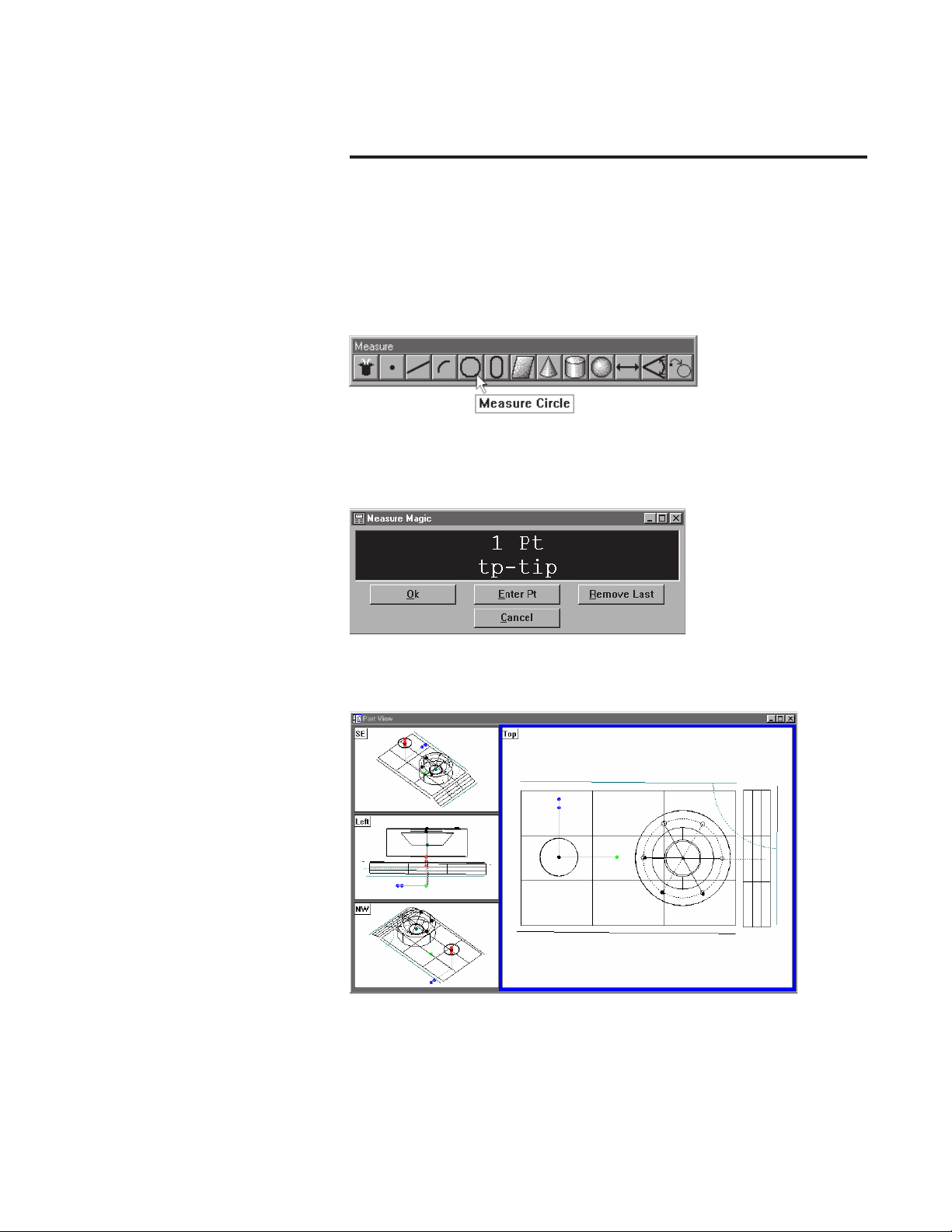
The QC-5000 measures part features using the simplest geometric components: points. Lines can be created from two points, circles from three
points, and cones from six points. Simply probe the points and the QC5000 measures the feature.
Once the required number of points are entered the QC-5000 displays
the feature in the part view window.
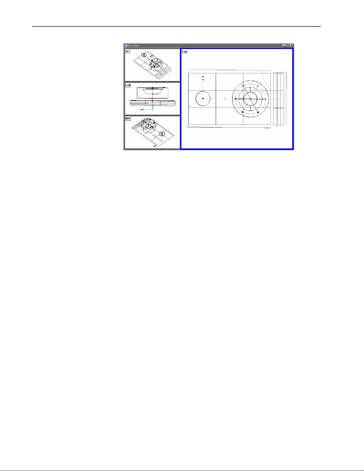
The QC-5000 continues building the part in the part view window as
features are added.
1-1
Page 20
Chapter 1 Overview
It is easy to use the QC-5000 because each measurement requires only a
few points. All geometry and mathematics are handled by the software.
Once the basic measuring principles are understood the QC-5000 can be
programmed to handle repetitive measuring tasks. Finally, inspection
and quality reports can be produced to document your results.
1-2
Page 21

About This Guide
Quadra-Chek® 5000
This guide is intended for end users of the QC-5000 metrology software,
supervisory, and installation personnel. A basic familiarity with the Windows computing environment and operation of attached measuring systems is assumed. Material in this guide is divided into five chapters covering everything from basic operation to system configuration. Keep this
guide in a convenient location for future reference.
Chapter 1: Overview
It all begins here, just point and click. There are only two things in the
QC-5000 interface: windows and toolbars. This chapter tells you which
is which and what to do with them. Understanding each window and
toolbar helps you get the most from the QC-5000.
Chapter 2: Quick Start
This chapter gets you up and running quickly. Use this chapter to learn
the most basic QC-5000 tasks. Each task in this chapter is described in
greater detail elsewhere in this guide.
Chapter 3: Probes
If it’s about probes, it’s in this chapter. Learn to manage and calibrate
VED and touch probes using probe library. All data comes into the QC5000 through probes. Use the information in this chapter and you won’t
go wrong.
Chapter 4: Programming
Programming puts it all together. This chapter shows you how to create
a streamlined, computer-prompted procedure to handle repetitive inspections with speed and accuracy. Use the programming feature to maximize your productivity with the QC-5000.
Chapter 5: Templates & Tolerancing
Picking up where chapter 4 leaves off this chapter covers datum magic,
measure magic, layers, offset alignments, and tolerancing. The QC-5000
organizes and present data in a number of formats. For your convenience
there are several data templates you can use to organize and present your
results. Use this chapter to learn how to use templates more efficiently.
This chapter also describes how to export QC-5000 data to other software.
Appendix A
Appendix A describes profile measurement. The appendix includes discussions of nominal profiles, profile tolerances, measurement results and
the on-screen tools and windows provided to facilitate profile measurement.
Index
There’s nothing worse than skimming through a user guide looking for
something when you’re in a hurry. To save you the hassle we indexed this
guide. Simply flip to the back, find your topic, and off you go.
1-3
Page 22
Chapter 1 Overview
Icons and Type Faces
This guide uses the following icons and type faces to highlight information:
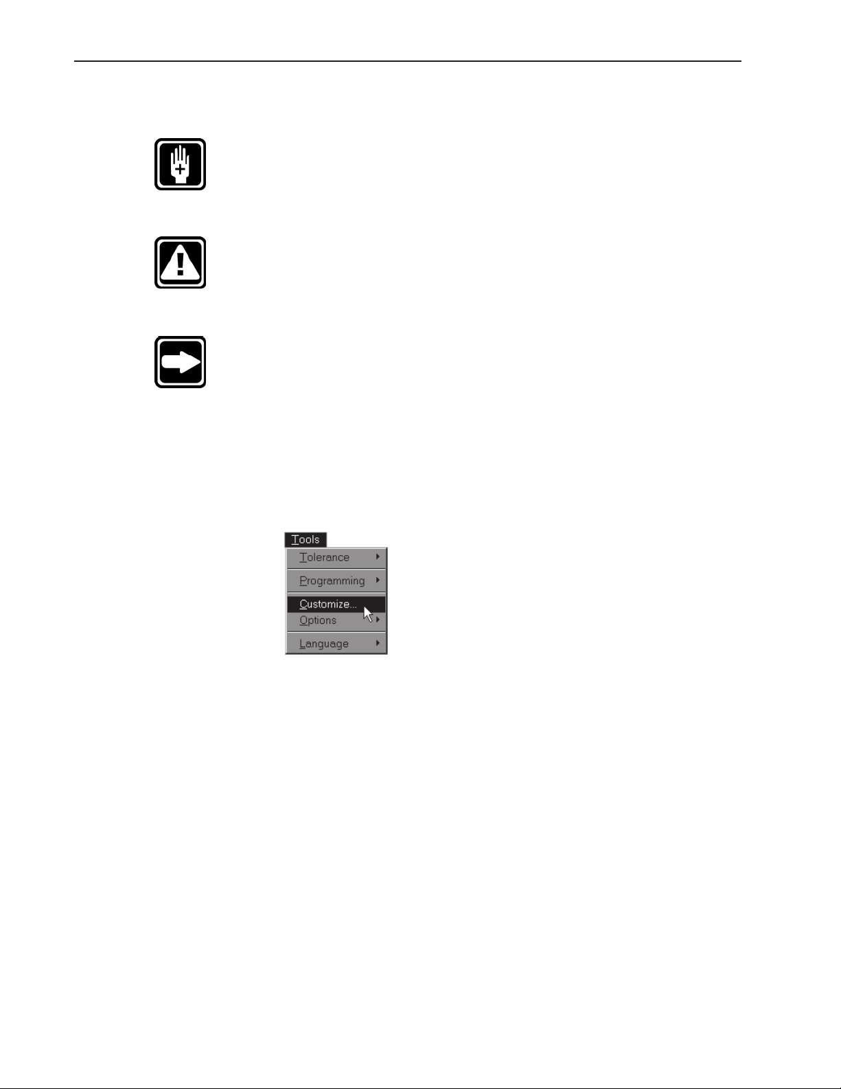
WARNING
The raised hand icon warns of situations or conditions that can lead to
personal injury or death. Do not proceed until you read and thoroughly
understand a warning message. Warning messages are shown in bold
type.
CAUTION
The exclamation point icon indicates situations or conditions that can
lead to measurement error, equipment malfunction or damage. Do not
proceed until you read and fully understand a caution message. Caution
messages are shown in bold type.
NOTE
The note icon indicates additional or supplementary information about
an activity or concept. Notes are shown in bold type.
Warnings, cautions, and notes are shown in this typeface.
Italics
Italics indicate menu items or button icons. For example,
Step 1
Select customize from the tools menu.
The italics instruct the user that customize is an item on the tools pulldown menu.
1-4
Page 23

Starting the QC-5000
Quadra-Chek® 5000
To open the QC-5000
Step 1
Double-click the QC-5000 icon on the Windows desktop.
The following screen indicates that the program is loading. It takes a
couple seconds for the program to load completely.
1-5
Page 24
Chapter 1 Overview
Windows and Toolbars
The QC-5000 uses a graphical user interface which means that instead of
typing in a bunch of complicated commands you can do things by pointing and clicking the mouse.
In this manual we’ll refer to the graphical user interface as the QC-5000
desktop. Although setups may vary, a typical QC-5000 desktop looks
like this.
1-6
There are only two things to point and click at on the QC-5000 desktop:
windows and toolbars. Here’s how to tell them apart.
Page 25
Quadra-Chek® 5000
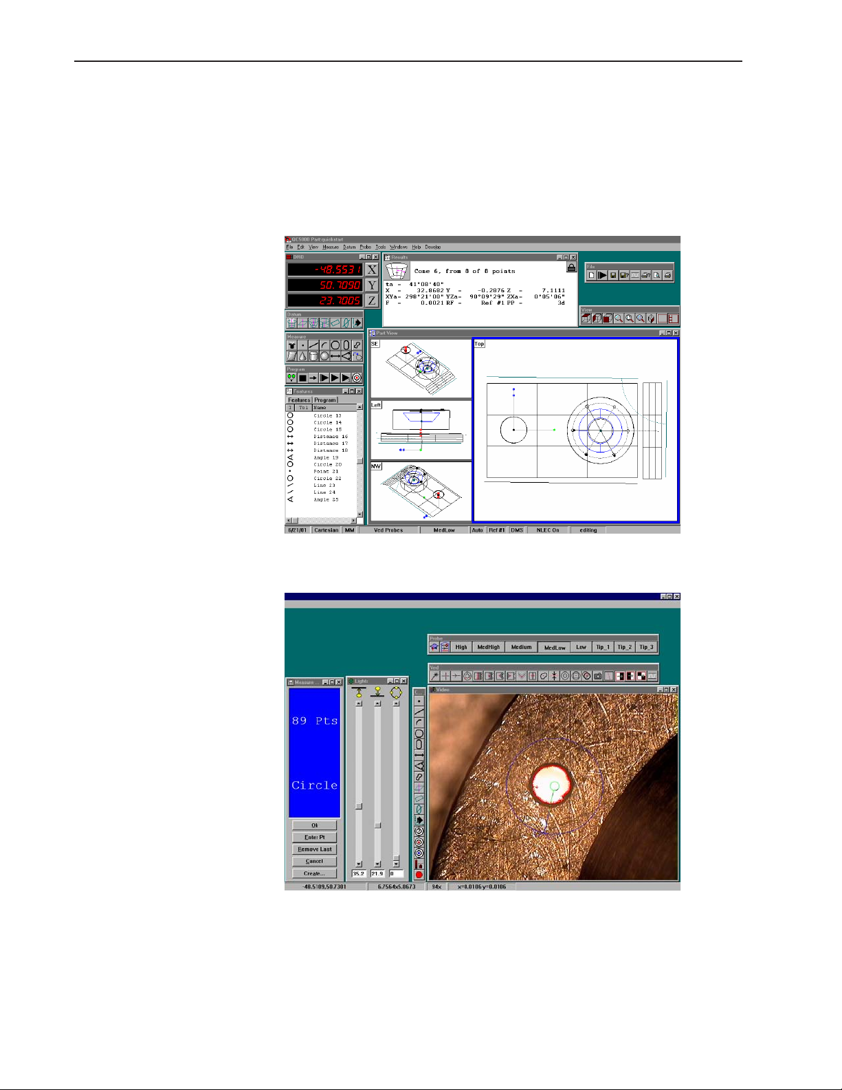
Windows display information. Some windows contain buttons or require input but their basic function is to display information. For example, the part view window displays a graphic of the part.
Toolbar buttons execute common tasks. For example, the measure toolbar contains buttons for various measurement functions. To perform a
measurement, click on the desired feature button (line, circle, plane, etc.).
1-7
Page 26
Chapter 1 Overview
QC-5000 Windows
The Results Window
The QC-5000 desktop has four windows: DRO (digital readout), results,
part view, and features list.
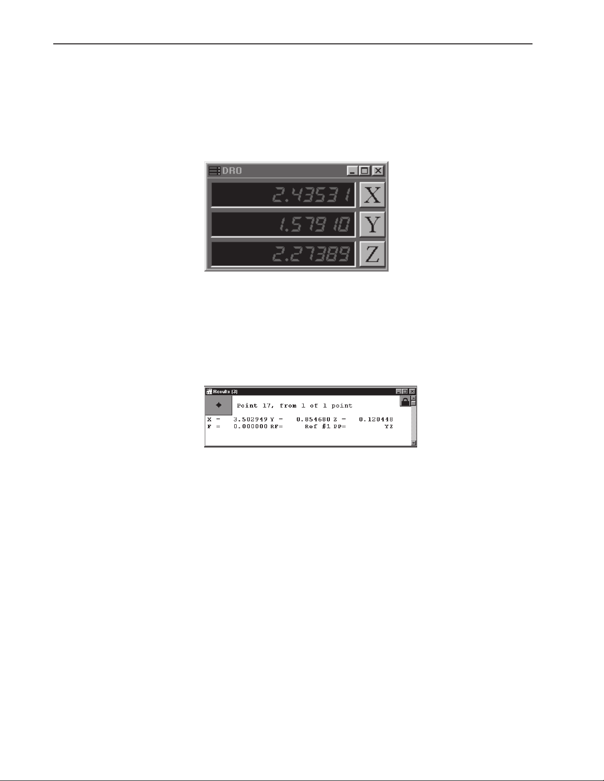
DRO
The DRO window displays the location of the X, Y, and Z axes (in mm or
inches) from the datum. Click the button beside the respective axis to
zero it.
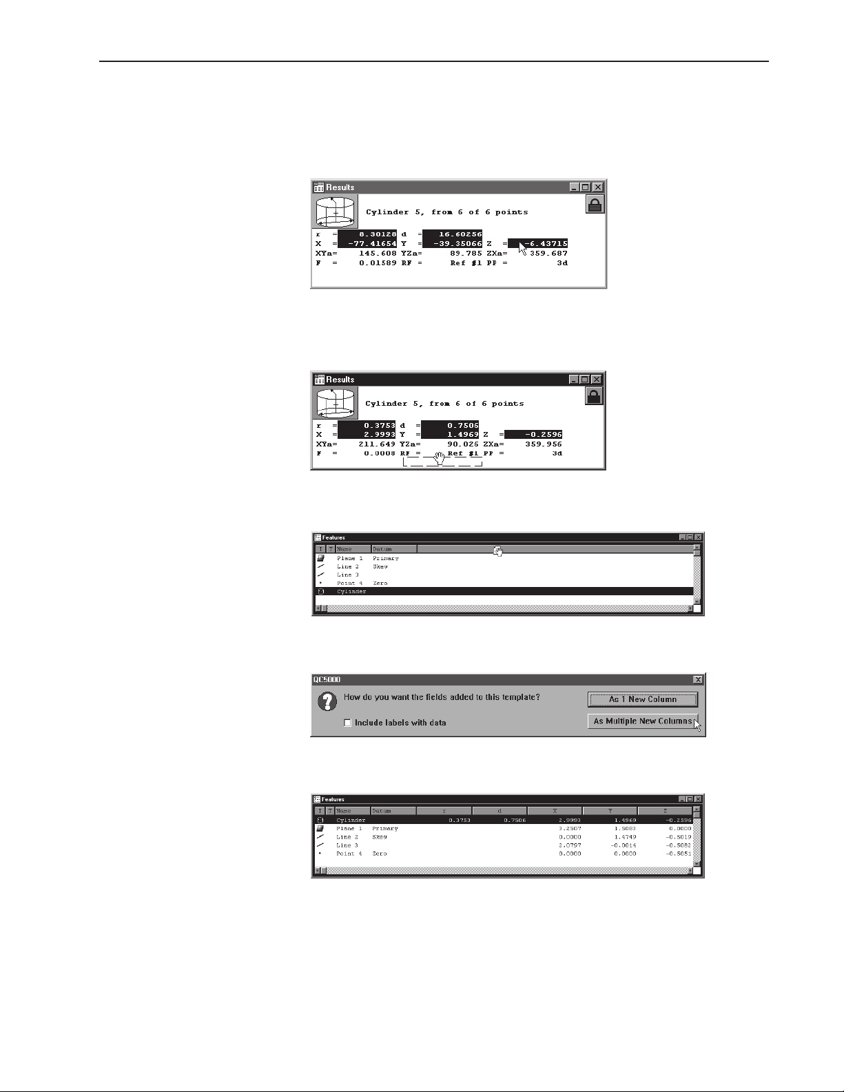
The results window displays the results of a feature measurement. This
window contains the following:
• Feature specifications
• Lock/unlock feature
• Feature type diagram / feature stamp
Feature Specifications
Feature information is displayed in the results window. Use the results
window to add information to the features list.
1-8
Page 27
Quadra-Chek® 5000
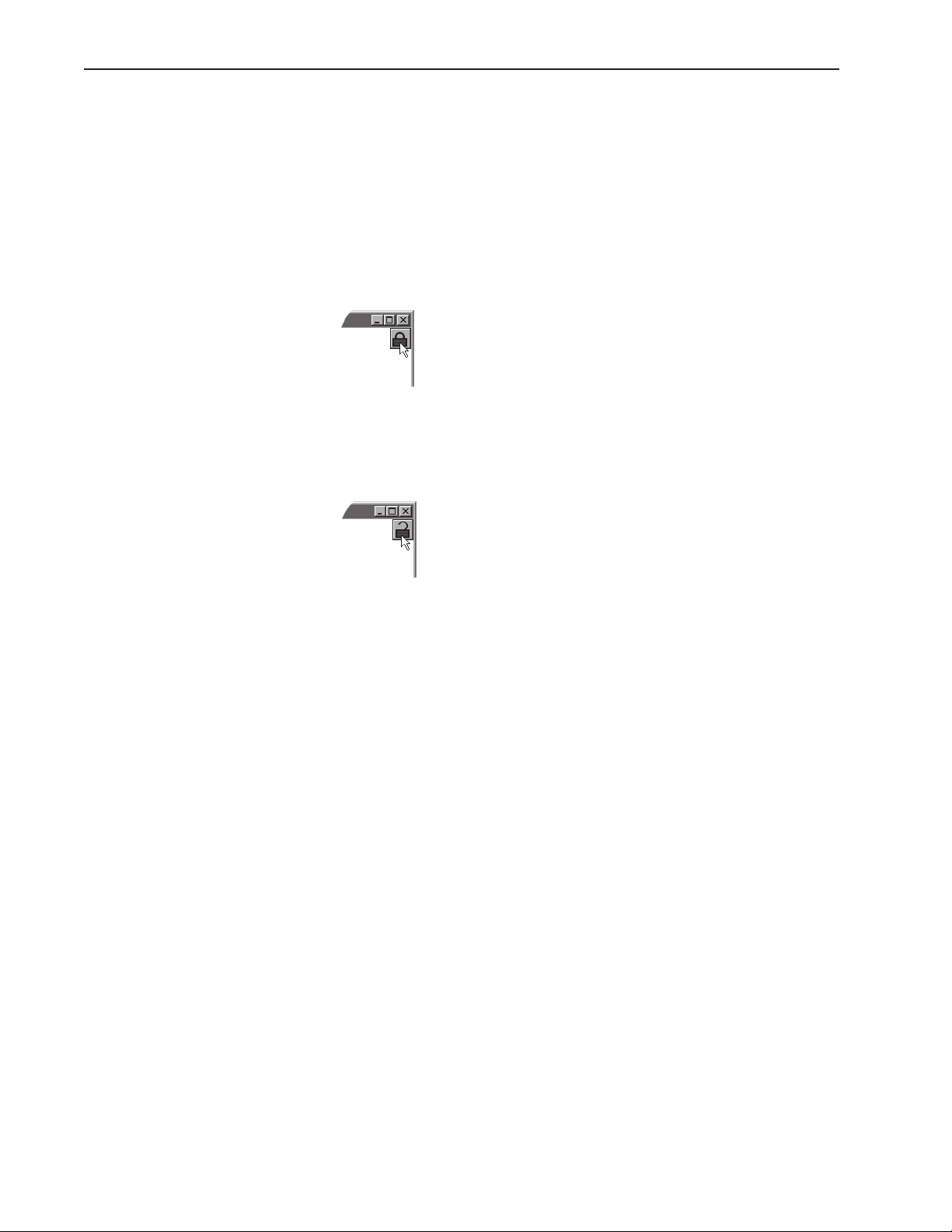
To move information from the results window to the features
list
Step 1
Highlight the desired information in the results window.
Step 2
Hold down the left mouse button and drag the information to the features list.
Step 3
Release the mouse button.
Step 4
Click the as multiple new columns button in the dialog box.
The feature window now displays the new parameters.
Information in this window is dependent on the type of feature. For
example, the window shows radius/diameter values for spherical features
but not for linear ones.
1-9
Page 28
Chapter 1 Overview
Locked/unlocked features
Some parts use more than one reference frame to measure all its features.
Locked features always display results from the reference frame they are
measured in the results window. Unlocked features are display results for
the current reference frame.
To unlock a feature
Step 1
Click the lock icon in the results window.
To lock a feature
Step 1
Click the lock icon in the results window.
1-10
Page 29
Quadra-Chek® 5000
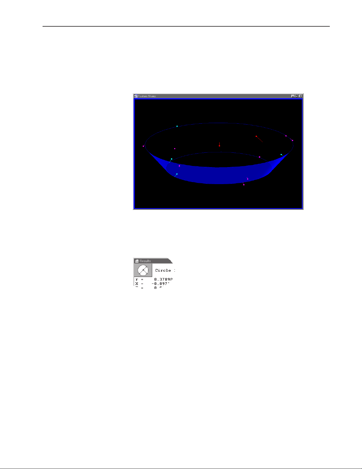
Feature type diagram /feature stamp
Clicking on the feature stamp icon opens the feature stamp window. The
feature stamp window shows a graphic display of the feature and the
distribution of the measurement points. Points discarded from the measurement are shown in red. Use the view toolbar to change the perspective in the feature stamp window.
To open the feature stamp window
Step 1
Click the feature stamp button in the results window.
1-11
Page 30
Chapter 1 Overview
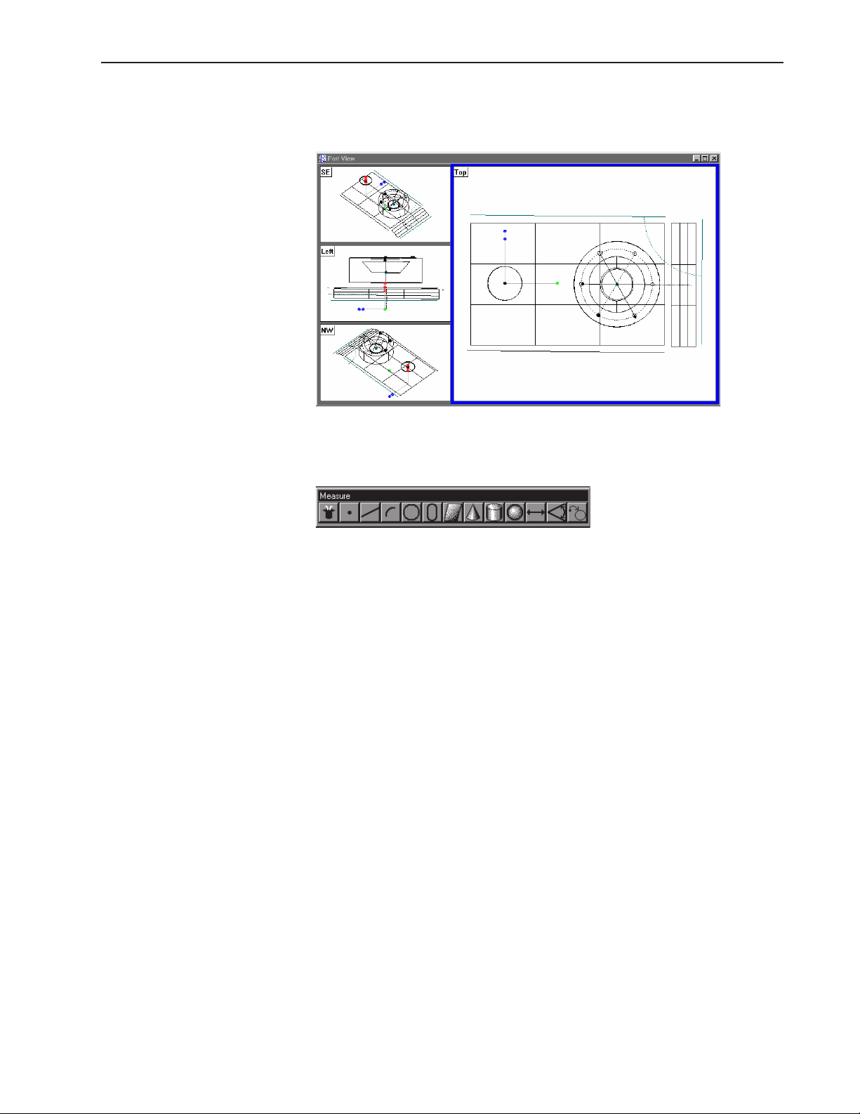
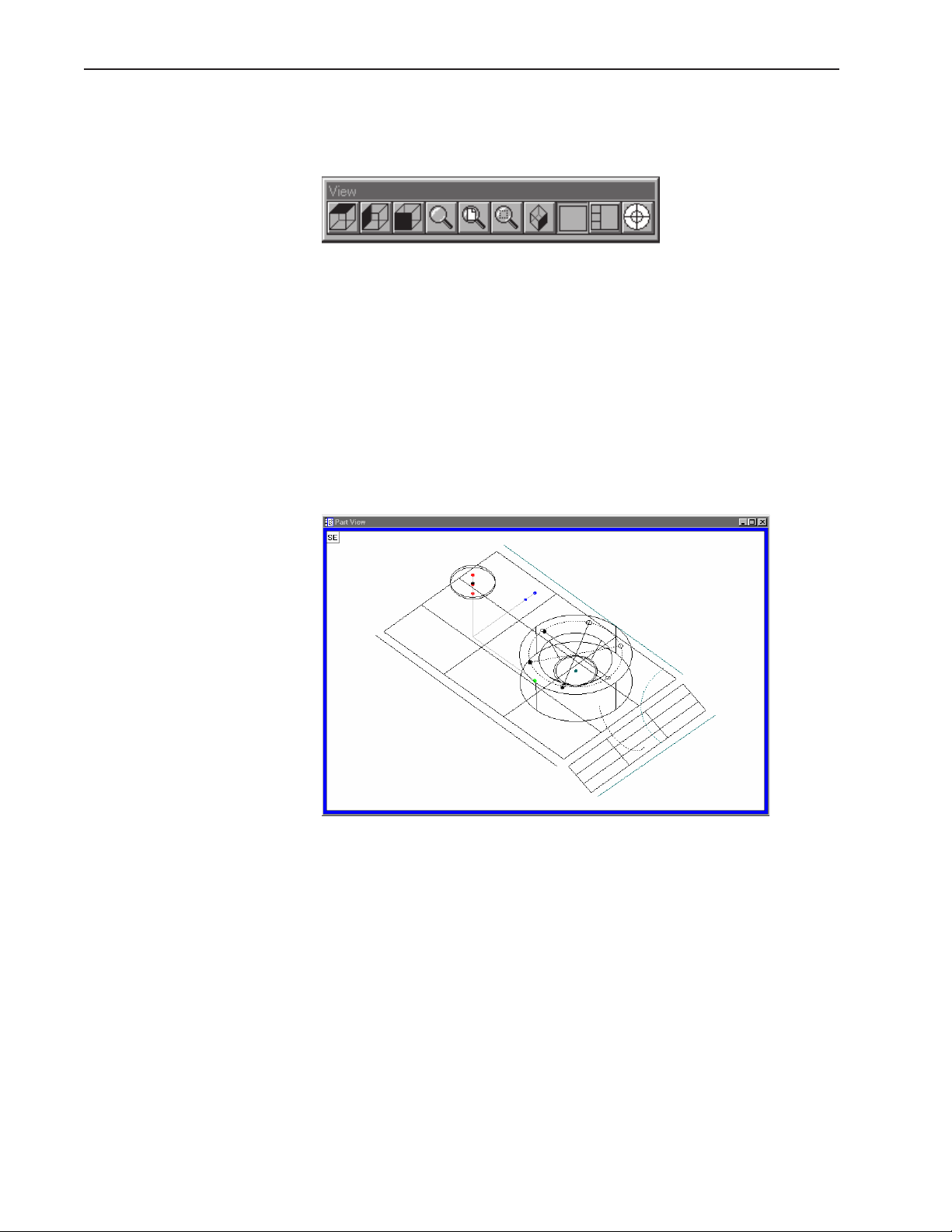
The Part View Window
The part view window displays a graphical representation of the part and
its features. Use the view toolbar to change the appearance of the part
view window.
This is a typical view toolbar. Remember that QC-5000 toolbars can be
customized. Toolbars pictured in this guide may vary from those on your
system.
Four pane part view displays the part from four separate vantage points.
Highlighted panes are outlined in blue. Place the cursor on the pane and
click to highlight. Only one pane can highlighted at a time.
The most common part view window appearances are shown here.
Single pane part view
1-12
Page 31

Four pane part view
Quadra-Chek® 5000
1-13
Page 32

Chapter 1 Overview
View Rotator
Change the display angle of the part view window with the view rotator.
To use the view rotator
Step 1
Click the view rotator button on the view toolbar OR select view rotator
from the view menu..
Step 2
Place the cursor over the view rotator window as shown.
Step 3
Move the cursor over the view rotator window until the part is displayed
as desired.
1-14
Page 33

Template Windows
Quadra-Chek® 5000
Template windows display data output from QC-5000 measurements and
programs. See Chapter 5: Tolerancing & Templates for more information
on using template windows.
Nest templates windows as shown to conserve space on the QC-5000
screen. For example, the window below contains the features, program,
and report templates nested in a single window. View the desired template by selecting the proper tab. In the example below, the feature tab is
selected.
To separate template windows
Step 1
Place the cursor over the desired tab as shown.
Step 2
Hold the left mouse button and drag the tab outside the current window
as shown.
1-15
Page 34

Chapter 1 Overview
Step 3
Release the left mouse button.
1-16
Page 35

Quadra-Chek® 5000
To nest template windows
Step 1
Place the cursor over the desired template window as shown.
Step 2
Hold the left mouse button and drag the template over the desired window.
Step 3
Release the mouse button.
1-17
Page 36

Chapter 1 Overview
Status Bar
The status bar runs across the bottom of the screen and displays such as:
• Date
• Type of coordinates (Polar/Cartesian)
• Selected units of measurement (in./mm)
• Active Layer
• Active probe tip
• Projection Plane
• Active Reference Frame
• Angle Display Mode
• SLEC/NLEC Status
• Recording or Editing Mode
Use the status bar to toggle between settings. Place the cursor over the
mm/inch section of the status bar. Click the mouse to toggle between
inches and millimeters. This is a quick way to change the units of measure. Other settings in the status bar can be toggled in the same way.
To add items to the status bar
Step 1
Select customize from the tools menu.
Step 2
Select the status bar tab as shown.
1-18
Page 37

Quadra-Chek® 5000
Step 3
Highlight the desired item as shown.
NOTE
Items currently in the status bar have an 'X' in the box next
to them. An empty box indicates the item is currently not
on the status bar.
Step 4
Click the show button.
Step 5
Click OK.
1-19
Page 38

Chapter 1 Overview
To delete items from the status bar
Step 1
Select customize from the tools menu.
Step 2
Select the status bar tab as shown.
Step 3
Highlight the desired item as shown.
NOTE
Items currently in the status bar have an 'X' in the box next
to them. An empty box indicates the item is currently not
on the status bar.
1-20
Page 39

Step 4
Click the hide button.
Step 5
Click OK.
Quadra-Chek® 5000
1-21
Page 40

Chapter 1 Overview
Main Menu Bar
Toolbars
This section shows the content of the QC-5000 pull-down menus. A
discussion of the various menu commands follows in later chapters. Use
this section to familiarize yourself with the menus. Place the cursor over
the desired menu and click to view pull-down menus.
Toolbars contain buttons that execute common tasks. Use toolbars instead of hunting through pull-down menus for commands. Simply click
the desired button and the task is begun. Toolbars correspond to the
main menu. For example, buttons in the view toolbar correspond to
commands on the view menu.
Datum toolbar
Use the datum toolbar to establish datums and reference frames. Buttons
in the datum toolbar correspond to items on the datum menu.
Measure toolbar
Use the measure toolbar to measure and construct features. Buttons on
the measure toolbar correspond to items on the measure menu.
Probe toolbar
Use the probe toolbar to access probe functions and settings. Buttons on
the probe toolbar correspond to items on the probe menu.
View toolbar
Use the view toolbar to adjust the part view window. Buttons on the view
toolbar correspond to items on the view menu.
1-22
Page 41

Quadra-Chek® 5000
Tolerance toolbar
Use the tolerance toolbar to perform tolerances on selected features. Buttons on the tolerance toolbar correspond to items on the tools menu.
Program toolbar
Use the program toolbar to access programming functions. Buttons on
the program toolbar correspond to items on the tools menu.
File toolbar
Use the file toolbar to access file functions. Buttons on the file toolbar
correspond to items on the file menu.
VED toolbar
Use the VED toolbar to access VED probe tools.
Custom toolbar
Use custom toolbars to create toolbars for specific tasks.
1-23
Page 42

Chapter 1 Overview
To place a toolbar on the QC-5000 desktop
Step 1
Select toolbars from the view menu.
Step 2
Highlight the desired toolbar as shown.
NOTE
Toolbars on the QC-5000 desktop have an 'X' in the box
next to them. An empty box indicates the item is currently
NOT on the desktop.
Step 3
Click the show button.
1-24
Page 43

Quadra-Chek® 5000
To remove a toolbar from the QC-5000 desktop
Step 1
Select toolbars from the view menu.
Step 2
Highlight the desired toolbar as shown.
NOTE
Toolbars on the QC-5000 desktop have an 'X' in the box
next to them. An empty box indicates the item is currently
NOT on the desktop.
Step 3
Click the hide button.
Customize your toolbars by adding or deleting buttons. Add buttons for
common tasks . Delete seldom used buttons to keep toolbar size manageable.
1-25
Page 44

Chapter 1 Overview
To add buttons to a toolbar
Step 1
Select customize from the tools menu.
Step 2
Select the toolbars tab in the customize dialog box.
Step 3
Highlight the desired toolbar in the toolbars list as shown.
Step 4
Highlight the desired button in the all possible buttons list.
Step 5
Click the copy button.
1-26
Page 45

Step 6
Click OK.
Quadra-Chek® 5000
1-27
Page 46

Chapter 1 Overview
To remove buttons from a toolbar
Step 1
Select customize from the tools menu.
Step 2
Select the toolbars tab in the customize dialog box.
Step 3
Highlight the desired toolbar in the toolbars list as shown.
Step 4
Highlight the desired button in the buttons in toolbar list.
Step 5
Click the remove button.
1-28
Page 47

Step 6
Click OK.
Quadra-Chek® 5000
1-29
Page 48

Chapter 1 Overview
1-30
Page 49

Getting Started
Chapter 2
Quick Start
Use this chapter to learn the basic operating principles of the QC-5000.
Instructions in this chapter show the user how to create a complete inspection program. The quick start program includes:
• 2 reference frames
• VED measurements
• Touch probe measurements
• 2-D features
• 3-D features
• Constructed features
• Tolerances
• Formulas
NOTE
Systems not equipped with touch probes can substitute or
omit the 3-D measurements in the quickstart program.
General Preparation
All tasks demonstrated are described in greater detail in other chapters.
Inexperienced users should review those chapters before attempting the
quick start program.
Follow the instructions in this section before beginning the quick start
program.
To open the QC-5000 software
Step 1
Double-click the QC-5000 icon on the Windows desktop.
The screen above indicates that the program is loading. It takes a couple
seconds for the program to load completely.
2-1
Page 50

Chapter 2 Quick Start
To set machine zero
Follow the machine zero procedure established by your supervisor, OEM,
or distributor before beginning this section.
To display the feature list
Step 1
Select open template from the windows menu.
Step 2
Select features.5ft as shown.
2-2
Step 3
Click OK in the dialog box.
Page 51

To display the program template
Step 1
Select open template from the windows menu.
Step 2
Select program.5ft as shown.
Quadra-Chek® 5000
Step 3
Click OK in the dialog box.
2-3
Page 52

Chapter 2 Quick Start
Nest template windows to keep the work space from getting too cluttered. Click on the tab to view the desired nested template.
To nest the template windows
Step 1
Place the cursor on the title bar of the window as shown.
Step 2
Hold the mouse button and place the window as shown.
2-4
Page 53

Quadra-Chek® 5000
Step 3
Release the mouse button.
Select the Active Probe
Select the touch probe as the active probe before recording the quick start
program.
Probing Technique
To select the active probe
Step 1
Click on the status bar until contact probes is displayed as shown.
The contact probe group is now active.
Probing technique refers to the method of moving CMM axes and entering point data with a touch probe. All features are made up of points and
all points are taken with probes. In order to get good results from the
QC5000 software it is important to use proper probe technique and to
input proper probe settings.
Good probing techniques
• approach the feature from a 90 degree angle
• approach the feature from a distance of at least 1mm
• do not probe a feature from an angle of 45 degrees or less
Bad probing techniques
• dragging probe across a part
• dropping probe off the edge of a part
2-5
Page 54

Chapter 2 Quick Start
Recording the Quick
Start Program
Follow the instructions in this section to record the quick start program.
Clearance moves
CAUTION
Use clearance moves to avoid collisions between the probe
and the part.
Clearance moves are necessary to create CNC paths around the part and
other obstructions. For example, to safely move the probe from point A
to point C, insert a clearance move at point B.
If the clearance moves are omitted, the probe will move in a straight line
from point A to point C. The resulting collision could damage the probe.
2-6
Page 55

Quadra-Chek® 5000
To insert a clearance move
Step 1
Move the probe to the desired clearance point. Select a point that will
allow the probe to travel safely away from obstacles.
Step 2
Click the goto here button on the program toolbar.
Use this procedure whenever directed to insert a clearance move in a
program.
2-7
Page 56

Chapter 2 Quick Start
Creating the Start Point
It is a good practice to start the program at a point that is well clear of all
part geometry. Move the probe to a clear position above the part. Make
certain the probe is clear of obstructions in the XY plane. Use this position as the start and end point for the inspection in this chapter.
To record the quick start program
NOTE
Open a new part file before recording the quick start
program.
Step 1
Click on the record button on the program toolbar.
The QC-5000 is now recording all actions as a part program. Use part
programs for repetitive inspection tasks. For example, if you need to
inspect 100 identical parts create a program while inspecting the first
part. Run the program to inspect the remaining 99 parts.
CAUTION
Unintentional probe collisions can result if the probe is not
well clear of the part when run. Begin and end programs
at points well clear of any obstruction.
2-8
Page 57

Quadra-Chek® 5000
To move the probe to the start point
Step 1
Position the touch probe at the start point as shown.
Step 2
Click on the goto button on the program toolbar.
2-9
Page 58

Chapter 2 Quick Start
Recording the Part
View Window
Follow the instructions below to record the part view display into a program. Use this procedure every time the part view window display is
changed while recording a program.
To record the part view window display
Step 1
Right-click on the program template and select special steps as shown.
Step 2
Select record part view display.
2-10
Page 59

Creating the Datum
Quadra-Chek® 5000
To create the primary plane
Step 1
Click the primary plane button on the datum toolbar.
Step 2
Probe the first point as shown.
Step 3
Probe the second point as shown.
Step 4
Insert a clearance move at clearance point 1 as shown.
2-11
Page 60

Chapter 2 Quick Start
Step 5
Click on the goto button on the program toolbar.
Step 6
Probe third point as shown.
Step 7
Probe fourth point as shown.
2-12
Step 8
Click OK in the dialog box.
Page 61

Quadra-Chek® 5000
The primary plane appears in the part view window.
2-13
Page 62

Chapter 2 Quick Start
Creating the
Secondary Alignment
To create a secondary alignment
Step 1
Click the secondary line button on the datum toolbar.
Insert a clearance move as shown.
Step 2
Click the goto button on the program toolbar.
Step 3
Probe the first point as shown.
Step 4
Insert a clearance move as shown.
2-14
Page 63

Step 5
Click the goto button on the program toolbar.
Step 6
Insert a clearance move as shown.
Quadra-Chek® 5000
Step 7
Click the goto button on the program toolbar.
Step 8
Probe the second point as shown.
Step 9
Probe the third point as shown.
2-15
Page 64

Chapter 2 Quick Start
Step 10
Click OK in the dialog box.
Step 11
Move the probe to the end point as shown.
Step 12
Click the goto button on the program toolbar.
The secondary alignment appears in the part view window.
2-16
Page 65

Creating the
Zero Point
Quadra-Chek® 5000
Measure the circle feature indicated to create the zero point.
Switch the active probe to VED for this measurement.
To activate the VED probe group
Step 1
Click on the status bar until VED probes is displayed as shown.
The VED probe group is now active. Use the following procedure to select
the desired magnification.
2-17
Page 66

Chapter 2 Quick Start
To select a magnification
Step 1
Click on the status bar until the desired magnification is displayed.
Position the circle in the video window as shown.
To create an arc tool
Step 1
Right click and select new VED probe from the list.
2-18
Page 67

Step 2
Place the wand tool as shown and click.
Quadra-Chek® 5000
Step 2
Place the wand tool as shown and click.
2-19
Page 68

Chapter 2 Quick Start
Step 3
Place the wand tool as shown and hold down the mouse button.
Step 4
Drag the wand tool in the desired scan direction.
2-20
An arc tool is created with edge scan in light-to-dark direction.
Page 69

Quadra-Chek® 5000
To re-size a VED probe tool
Step 1
Place the hand cursor over the over the tool as shown.
Step 2
Hold the left mouse button and move the hand cursor to the desired size.
2-21
Page 70

Chapter 2 Quick Start
To create a zero point
Step 1
Place the probe tool as shown.
Step 2
Click the center mouse button to fire the probe tool.
2-22
Page 71

Quadra-Chek® 5000
Step 3
Place the hand cursor over the corner of the probe tool as shown.
Step 4
Hold the mouse button and drag the corner of the probe tool to rotate as
shown.
2-23
Page 72

Chapter 2 Quick Start
Step 5
Move the part and place the probe tool as shown.
Step 6
Click the center mouse button to fire the probe tool.
2-24
Page 73

Step 7
Rotate the probe tool as shown.
Quadra-Chek® 5000
Step 8
Move the part and place the probe tool as shown.
2-25
Page 74

Chapter 2 Quick Start
Step 9
Click the center mouse button to fire the probe tool.
Step 10
Rotate the probe tool as shown.
2-26
Page 75

Quadra-Chek® 5000
Step 11
Move the part and place the probe tool as shown.
Step 12
Click the center mouse button to fire the probe tool.
2-27
Page 76

Chapter 2 Quick Start
Step 13
Click OK in the dialog box.
Step 14
Click the zero button on the datum toolbar.
Step 15
Check X and Y axes as shown.
Step 16
Click OK in the dialog box.
2-28
Page 77

Quadra-Chek® 5000
The reference frame appears in the part view window.
2-29
Page 78

Chapter 2 Quick Start
Save the Reference
Frame
To save the reference frame
Step 1
Click the save reference frame button on the datum toolbar.
Step 2
Type a name for the reference frame.
Step 3
Click OK in the dialog box.
Change the active probe group to contact probes. Use the following procedure.
2-30
Page 79

Quadra-Chek® 5000
To activate the contact probe group
Step 1
Click on the status bar as shown until contact probes appears in the box.
The contact probes group is now the active.
NOTE
The names assigned to probes and probe groups may vary
from those shown here.
NOTE
Dim the light controls to darken the live video window while
using the touch probe.
2-31
Page 80

Chapter 2 Quick Start
Touch Probe
Measurement
Use the touch probe group to complete the following measurements. Move
the probe to a safe start point well clear of the part geometry as shown.
CAUTION
Insert clearance moves as necessary to safely position the
probe.
2-32
Page 81

Quadra-Chek® 5000
To measure a circle
NOTE
Three points are required to measure a circle. Use more
points to increase accuracy.
Step 1
Probe the first point as shown.
Step 2
Probe the second point as shown.
Step 3
Probe the third point as shown.
2-33
Page 82

Chapter 2 Quick Start
Step 4
Probe the fourth point as shown.
Step 5
Click OK in the dialog box.
Step 6
Move the probe to the end point as shown.
Step 7
Click the goto button on the program toolbar.
2-34
Page 83

Quadra-Chek® 5000
The circle appears in the part view window.
Measurement results are displayed in the results window.
2-35
Page 84

Chapter 2 Quick Start
Measuring 3-D Features
Follow the directions in this section to measure a circle, a cone, a cylinder,
and a plane.
Change the part view window perspective to south east view for these
measurements. This will provide a better view for three-dimensional measuring.
To change the part view perspective
Step 1
Click the south east view button on the view toolbar.
The part view window appears as shown.
2-36
Step 2
Right-click on the program template and select special steps as shown.
Page 85

Quadra-Chek® 5000
Step 3
Select record part view display as shown.
The program template displays the steps as recorded.
2-37
Page 86

Chapter 2 Quick Start
To measure a cone
Step 1
Position the probe as shown.
Step 2
Probe 3 points around the top of the cone as shown.
Step 3
Position the probe over the center of the cone at about the same level as
points 1, 2, and 3 as shown.
Step 4
Click the goto button on the program toolbar.
2-38
Page 87

Quadra-Chek® 5000
Step 5
Probe 3 points around the bottom of the cone as shown.
Step 6
Position the probe above the center of the cone and clear of the part.
Step 7
Click the goto here button on the program toolbar.
Step 8
Probe two additional points as shown.
Step 9
Click OK in the dialog box.
2-39
Page 88

Chapter 2 Quick Start
Step 10
Position the probe above the center of the cone at about the same level as
points 1, 2, and 3 as shown.
Step 11
Click the goto here button on the program toolbar.
The cone appears in the part view window.
2-40
Measurement results are displayed in the results window.
Page 89

Quadra-Chek® 5000
To measure a cylinder
Step 1
Position the probe as shown.
CAUTION
Insert any clearance moves necessary to avoid probe
collisions.
NOTE
Points 1,2, and 3 are around the top of the cylinder.
Step 2
Probe the first point as shown.
Step 4
Insert clearance point 1 as shown.
Step 5
Click the goto button on the program toolbar.
2-41
Page 90

Chapter 2 Quick Start
Step 6
Insert clearance point 2 as shown.
Step 7
Click the goto button on the program toolbar.
Step 8
Probe the second point as shown.
2-42
Step 9
Insert clearance point 3 as shown.
Step 10
Click the goto button on the program toolbar.
Page 91

Step 11
Insert clearance point 4 as shown.
Step 12
Click the goto button on the program toolbar.
Quadra-Chek® 5000
Step 13
Probe the third point as shown.
Step 14
Insert clearance point 5 as shown.
2-43
Page 92

Chapter 2 Quick Start
Step 15
Click the goto button on the program toolbar.
NOTE
Points 4, 5, and 6 are around the bottom of the cylinder.
Step 16
Probe the fourth point as shown.
Step 17
Insert clearance point 6 as shown.
Step 18
Click the goto button on the program toolbar.
2-44
Page 93

Step 19
Insert clearance point 7 as shown.
Step 20
Click the goto button on the program toolbar.
Quadra-Chek® 5000
Step 21
Probe the fifth point as shown.
Step 22
Insert clearance point 8 as shown.
2-45
Page 94

Chapter 2 Quick Start
Step 23
Click the goto button on the program toolbar.
Step 24
Insert clearance point 9 as shown.
Step 25
Click the goto button on the program toolbar.
Step 26
Probe the sixth point as shown.
2-46
Page 95

Quadra-Chek® 5000
Step 27
Insert clearance point 10 as shown.
Step 28
Click the goto button on the program toolbar.
NOTE
Points 7 and 8 are taken around the middle of the cylinder.
Step 29
Probe the seventh point as shown.
Step 30
Insert clearance point 11 as shown.
2-47
Page 96

Chapter 2 Quick Start
Step 31
Click the goto button on the program toolbar.
Step 32
Insert clearance point 12 as shown.
Step 33
Click the goto button on the program toolbar.
Step 34
Probe the eighth point as shown.
Step 35
Click OK in the dialog box.
2-48
Page 97

Step 36
Move the probe to the end point as shown.
Step 37
Click the goto button on the program toolbar.
The cylinder appears in the part view window.
Quadra-Chek® 5000
Measurement results are displayed in the results window.
2-49
Page 98

Chapter 2 Quick Start
To measure a plane
Step 1
Position the probe as shown.
CAUTION
Insert any clearance moves necessary to avoid probe
collisions.
Step 2
Probe the first point as shown.
Step 3
Probe the second point as shown.
Step 4
Probe the third point as shown.
2-50
Page 99

Step 5
Probe the fourth point as shown.
Step 6
Click OK in the dialog box.
Quadra-Chek® 5000
Step 7
Move the probe to the end point as shown.
Step 8
Click the goto button on the program toolbar.
2-51
Page 100

Chapter 2 Quick Start
The plane appears in the part view window.
Measurement results are displayed in the results window.
2-52
 Loading...