

Page 1
Operating Instructions
IK 5000
QUADRA-CHEK
(QC 5000)
Manual 3D Systems
English (en)
2/2010
Page 2

Page 3

Quadra-Chek® 5000
User’s Guide
Page 4

Proprietary notice
Disclaimer
All information set forth in this document, all rights to such information, any and all inventions disclosed herein and any patents that might
be granted by employing the materials, methods, techniques or apparatus
described herein are the exclusive property of Metronics Incorporated,
Bedford, New Hampshire.
No part of this document may be reproduced, stored in a retrieval system, or transmitted in any form or by any means, electronic, mechanical,
photocopying, recording, or otherwise, without the prior permission of
Metronics Incorporated. The information contained herein is designed
only for use with the Quadra-Chek 5000 Metrology Software. Metronics
Incorporated is not responsible for any use of this information as applied
to any other apparatus.
The information contained in this document is subject to change without notice. Metronics Incorporated assumes no responsibility or liability
for any errors or inaccuracies contained herein, or for incidental or consequential damage in connection with the furnishing, performance, or use
of this guide.
Metronics Inc. shall not be liable to the purchaser of this product or third
parties for damages, losses, costs, or expenses incurred by the purchaser
or third parties as a result of: accident, misuse, or abuse of this product or
unauthorized modifications, repairs, or alterations to this product, or failure to strictly comply with Metronics Incorporated’s operating and maintenance instructions.
Trademarks
Printing History
Metronics, Quadra-Chek, Quadra-Chek 5000, and QC5000 are registered trademarks of Metronics Incorporated.
Other product names used herein are for identification purposes only
and may be trademarks of their respective owners. Metronics Incorporated disclaims any and all rights to those marks.
April 2001 First Printing
Revision 1.0
Part Number: 11A10516
Software Version 2.2
Printed in the USA.
Page 5

Page 6

Page 7

QC5000 User’s Guide
Contents
Chapter 1: Overview .................................................. 1
Welcome to the QC5000 ...................................................................................1
About This Guide ...............................................................................................3
Chapter 1: Overview ........................................................................................................................................ 3
Chapter 2: Using Probes ................................................................................................................................... 3
Chapter 3: General Measuring ......................................................................................................................... 3
Chapter 4: Advanced Measuring & Output...................................................................................................... 3
Chapter 5: Programming.................................................................................................................................. 3
Chapter 6: System Setup & Configuration ....................................................................................................... 3
Index ................................................................................................................................................................ 3
Icons and Type Faces.........................................................................................4
Warning ........................................................................................................................................................... 4
Caution ............................................................................................................................................................ 4
Note................................................................................................................................................................. 4
Italics................................................................................................................................................................ 4
Starting The QC5000 .........................................................................................5
To open the QC5000 ....................................................................................................................................... 5
Windows and Toolbars......................................................................................6
QC5000 Windows ..............................................................................................8
DRO................................................................................................................................................................ 8
The Results Window ..........................................................................................8
Feature Specifications ....................................................................................................................................... 8
To move information from the results window to the features list ..................................................................... 9
Locked/unlocked features ............................................................................................................................... 10
To unlock a feature......................................................................................................................................... 10
To lock a feature ............................................................................................................................................. 10
Feature type diagram /feature stamp ............................................................................................................... 11
To open the feature stamp window................................................................................................................. 11
The Part View Window....................................................................................12
Single pane part view...................................................................................................................................... 12
Four pane part view........................................................................................................................................ 12
View Rotator ................................................................................................... 13
To use the view rotator ................................................................................................................................... 13
Template Windows ..........................................................................................14
To separate template windows ........................................................................................................................ 14
To nest template windows .............................................................................................................................. 16
Status Bar ........................................................................................................17
To add items to the status bar ......................................................................................................................... 18
To delete items from the status bar ................................................................................................................. 19
Main Menu Bar ................................................................................................22
File ................................................................................................................................................................. 22
Edit ................................................................................................................................................................ 22
View............................................................................................................................................................... 23
Measure.......................................................................................................................................................... 24
Datum ........................................................................................................................................................... 24
Probe.............................................................................................................................................................. 25
Page 8

Contents
Tools .............................................................................................................................................................. 26
Windows ........................................................................................................................................................ 26
Help ............................................................................................................................................................... 26
Toolbars ...........................................................................................................27
Datum toolbar ............................................................................................................................................... 27
Measure toolbar ............................................................................................................................................. 27
Probe toolbar.................................................................................................................................................. 27
View toolbar................................................................................................................................................... 27
Tolerance toolbar............................................................................................................................................ 27
Program toolbar ............................................................................................................................................. 27
File toolbar ..................................................................................................................................................... 28
To place a toolbar on the QC5000 desktop .................................................................................................... 28
To remove a toolbar from the QC5000 desktop ............................................................................................. 29
To add buttons to a toolbar ............................................................................................................................ 30
To remove buttons to a toolbar ....................................................................................................................... 32
Chapter 2: Quick Start.............................................. 33
Quick Start .......................................................................................................33
Set machine zero ............................................................................................................................................ 33
Create a reference frame ................................................................................................................................. 34
Measure a line (minimum 2 points)................................................................................................................ 37
Measure a circle (minimum 3 points) ............................................................................................................. 37
Measure a cone (minimum 6 points) .............................................................................................................. 38
Measure a cylinder (minimum 6 points) ......................................................................................................... 39
Measure a distance ......................................................................................................................................... 40
Save a part file ................................................................................................................................................ 41
Chapter 3: Using Probes .......................................... 43
Probing Technique...........................................................................................43
Good probing techniques ............................................................................................................................... 43
Bad probing techniques .................................................................................................................................. 43
Probe Toolbar ..................................................................................................43
Probe teach..................................................................................................................................................... 43
Probe compensation off.................................................................................................................................. 43
Cardinal probe compensation......................................................................................................................... 44
Polar probe compensation .............................................................................................................................. 44
Auto enter ...................................................................................................................................................... 44
Probe library .................................................................................................................................................. 44
Probe compensation ....................................................................................... 45
Probe compensation off.................................................................................................................................. 45
Cardinal probe compensation......................................................................................................................... 45
Polar probe compensation .............................................................................................................................. 45
To activate probe compensation ..................................................................................................................... 46
Auto Enter .......................................................................................................47
To activate auto enter ..................................................................................................................................... 47
Probe Library ................................................................................................... 47
Probe Families & Groups.................................................................................48
HardProbe group ........................................................................................................................................... 48
TouchProbe group .......................................................................................................................................... 49
StarProbe group ............................................................................................................................................. 49
To create a new probe group........................................................................................................................... 50
Probe Calibration ............................................................................................52
Master probe tips ........................................................................................................................................... 52
To teach (qualify) a master probe tip .............................................................................................................. 53
To teach (qualify) a non-master probe tip ....................................................................................................... 54
Page 9

Quadra-Chek® 5000
Changing Probes .............................................................................................55
To view the probes in a group........................................................................................................................ 55
To change the current probe tip...................................................................................................................... 55
To add probe tips ........................................................................................................................................... 57
To delete probe tips ........................................................................................................................................ 59
Probe Results Window ....................................................................................60
Chapter 4: General Measuring................................. 63
Getting Started ...............................................................................................63
Set machine zero ............................................................................................................................................ 63
To set machine zero ........................................................................................................................................ 63
Reference Frame............................................................................................................................................. 66
Projection planes ............................................................................................................................................ 67
Machine coordinates ...................................................................................................................................... 68
Part coordinates.............................................................................................................................................. 68
To create a reference frame ............................................................................................................................. 69
Measuring 2D Features ...................................................................................72
To probe a point............................................................................................................................................. 72
To probe a line (2 points) ............................................................................................................................... 73
To probe an arc (3 points) .............................................................................................................................. 74
To probe a circle (3 points)............................................................................................................................. 75
To probe a slot (5 points) ............................................................................................................................... 76
To probe a plane (3 points) ............................................................................................................................ 77
Measuring 3D Features ...................................................................................78
To probe a cone (3 points).............................................................................................................................. 78
To probe a cylinder (6 points) ........................................................................................................................ 79
To probe a sphere (5 points) ........................................................................................................................... 80
Constructing Features ....................................................................................81
Point Constructions ........................................................................................81
To construct a center point ............................................................................................................................. 81
To construct an apex point ............................................................................................................................. 82
To construct an application point ................................................................................................................... 83
To construct an anchor point ......................................................................................................................... 84
To construct bounding points......................................................................................................................... 85
To construct a point from 2 intersecting lines ................................................................................................. 86
To construct a closest point of approach point................................................................................................ 87
To construct points from intersecting circles ................................................................................................... 88
To construct a midpoint from two circles ....................................................................................................... 89
To construct a point from the intersection of a line and a circle ...................................................................... 90
To construct a midpoint from 2 positional features......................................................................................... 91
To construct a perpendicular point from a positional feature and a plane ....................................................... 92
To construct a point from a linear feature and a plane .................................................................................... 93
To construct a point from the intersection of 3 planes .................................................................................... 94
Line Constructions ..........................................................................................95
To construct an axis line from a linear feature................................................................................................. 95
To construct a plane axis line (Normal Line) .................................................................................................. 96
To construct a midline from the sides of a slot ................................................................................................ 97
To construct a 2 point line from two positional features ................................................................................. 98
To construct a tangent line from 2 radial positional features ........................................................................... 99
To construct a line from the intersection of 2 planes..................................................................................... 101
To construct a bisector of 2 linear features .................................................................................................... 102
To construct a perpendicular bisector of 2 linear features.............................................................................. 103
To construct a closest point of approach line from 2 linear features ............................................................. 105
To construct a line from a positional feature perpendicular to a linear feature ............................................... 107
To construct a line parallel to a linear feature using a positional feature ........................................................ 108
Page 10

Contents
To construct a perpendicular line through a plane and a positional feature ................................................... 110
To construct a rotated line from the leg of an angle and the angle ................................................................ 111
To construct a gage line ................................................................................................................................ 112
To construct a line by projecting an existing line on a new projection plane ................................................. 114
Circle Constructions ......................................................................................115
To construct a circle from a sphere ............................................................................................................... 115
To construct a circle from a cone .................................................................................................................. 116
To construct a circle from an intersecting plane and cylinder ........................................................................ 117
To construct a circle from an intersecting cylinder and cone ......................................................................... 118
To construct a circle tangent to 2 intersecting lines ....................................................................................... 119
To change the location of a tangent circle ..................................................................................................... 120
Plane Constructions ......................................................................................121
To construct a plane from the midpoint of a line .......................................................................................... 121
To construct a plane from a line and a positional feature .............................................................................. 122
To construct a midplane from 2 planes......................................................................................................... 123
To construct a perpendicular midplane from 2 planes................................................................................... 124
Sphere Constructions....................................................................................125
To construct a sphere from a cone ................................................................................................................ 125
Cylinder Constructions .................................................................................126
To construct a cylinder from to 2 co-axial circles .......................................................................................... 126
Cone Constructions.......................................................................................127
To construct a cone from 2 co-axial circles.................................................................................................... 127
Measuring Relations .....................................................................................128
Distance ....................................................................................................................................................... 128
Angle............................................................................................................................................................ 128
Distance Constructions .................................................................................129
To construct the length of an axis ................................................................................................................. 129
To construct a duplicate distance .................................................................................................................. 130
To construct a reverse direction distance ....................................................................................................... 131
To construct an absolute distance ................................................................................................................. 132
To construct a center to center distance ........................................................................................................ 133
To construct a farthest edge distance............................................................................................................. 134
To construct a nearest edge distance ............................................................................................................. 135
To construct a distance from a positional feature perpendicular to a linear feature ........................................ 136
To construct the nearest to line distance ....................................................................................................... 137
To construct the farthest to line distance ...................................................................................................... 138
To construct a distance from a positional feature to a plane .......................................................................... 139
To construct a center to plane distance from a sphere ................................................................................... 140
To construct the nearest plane distance from a sphere................................................................................... 141
To construct the farthest plane distance from a sphere .................................................................................. 142
To construct a bounded line distance from 2 lines ........................................................................................ 143
To construct a nearest bounded line distance from 2 lines ............................................................................ 144
To construct a farthest bounded line distance from 2 lines............................................................................ 146
To construct an unbounded distance from 2 linear features .......................................................................... 148
To construct a distance between 2 co-axial planes ......................................................................................... 150
Angle Constructions......................................................................................151
To construct an angle from 2 linear features ................................................................................................. 151
Saving Your Work ..........................................................................................152
To save a part file.......................................................................................................................................... 152
To export to a CAD file................................................................................................................................ 154
To export to SPC software ............................................................................................................................ 156
To export to Microsoft Access....................................................................................................................... 158
Page 11

Quadra-Chek® 5000
Chapter 5: Advanced Measuring & Output........... 161
Datum Magic .................................................................................................161
To create a datum using datum magic........................................................................................................... 161
Measure Magic ..............................................................................................163
To measure a point using measure magic ...................................................................................................... 163
To measure a line using measure magic (2 points) ........................................................................................ 164
To measure an arc using measure magic (3 points)........................................................................................ 164
To measure a circle using measure magic (3 points) ...................................................................................... 165
To measure a plane using measure magic (3 points)...................................................................................... 165
To measure a cone using measure magic (6 points) ....................................................................................... 166
To measure a cylinder using measure magic (6 points).................................................................................. 167
To measure a sphere using measure magic (4 points) .................................................................................... 168
Layers.............................................................................................................169
To create a new layer .................................................................................................................................... 169
Current Layer............................................................................................................................................... 170
To set a layer as current ................................................................................................................................ 170
To assign features to new layers .................................................................................................................... 172
Displaying Layers ..........................................................................................174
To hide a layer .............................................................................................................................................. 174
To show a hidden layer ................................................................................................................................. 175
To turn off a layer......................................................................................................................................... 177
To turn on a layer ......................................................................................................................................... 179
To assign a color to a layer ............................................................................................................................ 181
Alternate Datums ..........................................................................................184
To rotate the reference frame (datum) .......................................................................................................... 184
Offset Alignments .........................................................................................186
To perform an offset alignment (primary plane) ........................................................................................... 186
To perform an offest alignment (secondary line)........................................................................................... 189
To perform an offest alignment (zero point) ................................................................................................. 192
Tolerancing ....................................................................................................194
Tolerance Toolbar......................................................................................................................................... 194
To view the tolerance toolbar........................................................................................................................ 194
Bi-directional tolerance (circles, points, arcs, spheres) ................................................................................... 196
To perform a bi-directional tolerance............................................................................................................ 196
Pass/ Fail Displays ........................................................................................................................................ 199
True position tolerance (circles, points arcs, spheres) .................................................................................... 199
To perform a true position tolerance............................................................................................................. 199
MMC/LMC tolerance (circles, points arcs, spheres) ..................................................................................... 202
To perform a MMC tolerance ...................................................................................................................... 202
To perform a LMC....................................................................................................................................... 205
Concentricity tolerance (circles, arcs)............................................................................................................ 208
To perform a concentricity tolerance ............................................................................................................ 208
Straightness tolerance (lines)......................................................................................................................... 211
To perform a straightness tolerance (lines) .................................................................................................... 211
Circularity/sphericity tolerance (circles, spheres)........................................................................................... 213
To perform a circularity tolerance ................................................................................................................. 213
To perform a sphericity tolerance ................................................................................................................. 215
Cylindricity tolerance (cylinders) .................................................................................................................. 217
To perform a cylindricty tolerance ................................................................................................................ 217
Flatness tolerance (planes) ............................................................................................................................ 219
To perform a flatness tolerance ..................................................................................................................... 219
Perpendicularity tolerance (lines, cylinders, cones)........................................................................................ 221
To perform a perpendicularity tolerance ....................................................................................................... 221
Parallelism/Co-planarity tolerance (linear features)....................................................................................... 223
Page 12

Contents
To perform a parallelism tolerance................................................................................................................ 223
To perform a co-planarity tolerance .............................................................................................................. 225
Circular runout tolerance ............................................................................................................................. 227
To perform a circular runout tolerance ......................................................................................................... 227
Angle tolerance............................................................................................................................................. 229
To perform an angle tolerance ...................................................................................................................... 229
Width tolerance ........................................................................................................................................... 231
To perform a width tolerance ....................................................................................................................... 231
Chapter 6: Templates ............................................. 233
Templates ......................................................................................................233
Features Template .........................................................................................235
To open the features template....................................................................................................................... 235
Adding Data to ..............................................................................................237
Templates ......................................................................................................237
To drag and drop a single results window field into the features list .............................................................. 237
To drag and drop a multiple results window fields into the features list......................................................... 238
Sorting the Features List ............................................................................................................................... 239
To sort data in the features list ...................................................................................................................... 239
Reports Template ..........................................................................................240
To open the reports template ........................................................................................................................ 240
Adding Data to the Reports Template .......................................................................................................... 242
To drag and drop a single results window field into the reports template ...................................................... 242
To drag and drop a multiple results window fields into the reports template................................................. 243
Sorting Data in the Reports Template........................................................................................................... 244
To sort data in the reports template .............................................................................................................. 244
Report Headers..............................................................................................245
To show a report header ............................................................................................................................... 245
Customizing Report Headers........................................................................................................................ 247
To place a graphic in a report header ........................................................................................................... 247
To arrange text and graphics in a report header ............................................................................................ 248
Automated Text Input & Prompting ............................................................249
Overlays .........................................................................................................250
To save a report header as an overlay ............................................................................................................ 250
To place an overlay in a report header ........................................................................................................... 251
Program Template ........................................................................................................................................ 252
To open the program template ..................................................................................................................... 252
Template Properties ...................................................................................................................................... 254
To access the template features dialog box .................................................................................................... 254
Template Features Dialog Box ...................................................................................................................... 255
Display tab ................................................................................................................................................... 255
Filters tab ......................................................................................................260
To create a filter ............................................................................................................................................ 261
To modify a filter .......................................................................................................................................... 267
To remove a filter ......................................................................................................................................... 269
Misc tab (miscellaneous) .............................................................................................................................. 270
Column Properties ........................................................................................271
Standard column properties.......................................................................................................................... 271
Appearence tab ............................................................................................................................................. 271
Formulas tab ................................................................................................................................................ 271
Parantheses( ) ............................................................................................................................................... 271
Brackets [ ] ................................................................................................................................................... 272
Quote marks "" ............................................................................................................................................ 272
Min/Max...................................................................................................................................................... 273
Sample Formula ............................................................................................274
Page 13

Quadra-Chek® 5000
To create the sample formula ........................................................................................................................ 274
To modify a formula ..................................................................................................................................... 279
To remove a formula .................................................................................................................................... 281
Runs Template ...............................................................................................282
To open the runs template ............................................................................................................................ 282
To add data to the runs template .................................................................................................................. 283
Nesting Template ..........................................................................................284
Windows ........................................................................................................284
To nest template windows ............................................................................................................................ 284
To separate template windows ...................................................................................................................... 284
Creating New Templates...............................................................................286
To create a new template .............................................................................................................................. 286
Export ............................................................................................................288
To export a tab delimited file to a spreadsheet .............................................................................................. 288
To export a CSV (comma separated value) file to a spreadsheet .................................................................... 290
Chapter 7: Programming ....................................... 293
Programming Overview ................................................................................293
The Program Toolbar.....................................................................................294
Record/Edit Program .................................................................................................................................... 294
Pause Program .............................................................................................................................................. 294
New Run...................................................................................................................................................... 294
Run Program From Current Step ................................................................................................................. 294
Run Just Current Step .................................................................................................................................. 294
Recording a Program ....................................................................................295
To create a program ...................................................................................................................................... 295
To open a saved program .............................................................................................................................. 297
Running A Program .......................................................................................298
To run a program ......................................................................................................................................... 298
Sample Program............................................................................................299
To record the sample program ...................................................................................................................... 299
Creating User Messages................................................................................308
To Insert A User Message ............................................................................................................................. 308
Expanding the Program Toolbar ..................................................................309
Toggle Break Point ....................................................................................................................................... 309
Program Comment ...................................................................................................................................... 309
Edit Steps ..................................................................................................................................................... 309
If-Goto......................................................................................................................................................... 309
If-Then ........................................................................................................................................................ 309
Else .............................................................................................................................................................. 310
Else-If........................................................................................................................................................... 310
Super Step .................................................................................................................................................... 310
Goto Label ................................................................................................................................................... 310
Offset Positions ............................................................................................................................................ 310
Toggle Break Point ....................................................................................................................................... 310
Program Comment ...................................................................................................................................... 311
Edit Steps ..................................................................................................................................................... 311
If-Goto......................................................................................................................................................... 311
If-Then ........................................................................................................................................................ 311
Else .............................................................................................................................................................. 311
Else-If........................................................................................................................................................... 311
Super Step .................................................................................................................................................... 312
Goto Label ................................................................................................................................................... 312
Offset Positions ............................................................................................................................................ 312
Page 14

Contents
To add buttons to a toolbar ......................................................................................................................... 313
To delete buttons from a toolbar .................................................................................................................. 315
Conditional Statements ................................................................................317
Test Conditions ............................................................................................................................................ 317
Actions ......................................................................................................................................................... 317
Arithmetic Operators ................................................................................................................................... 318
If-Goto Statement ........................................................................................................................................ 319
If-Then Statement ........................................................................................................................................ 320
Else Statement .............................................................................................................................................. 321
Else-If Statement .......................................................................................................................................... 322
Parantheses( ) ............................................................................................................................................... 323
Brackets [ ] ................................................................................................................................................... 323
Quote marks "" ............................................................................................................................................ 324
Min/Max...................................................................................................................................................... 324
Chapter 8: System Setup & Configuration ........... 327
Before You Begin ...........................................................................................327
Hardware Setup ............................................................................................327
Encoder Setup ...............................................................................................328
To setup encoders ......................................................................................................................................... 328
Troubleshooting ............................................................................................332
Encoder Setup ...............................................................................................332
Encoder setup shows continual errors, beeps, or inconsistent wave output .................................................... 332
Encoder setup show one or two errors after calibrating an axis...................................................................... 333
Encoder setup shows numerous errors after calibrating an axis ..................................................................... 334
Wave (amplitude) calibrates, phase does not calibrate ................................................................................... 337
TTL encoders will not calibrate .................................................................................................................... 338
Status bar freezes during calibration or other error message .......................................................................... 340
Encoder setup icon is missing ....................................................................................................................... 342
QC5000 counts double, half, or wrong ........................................................................................................ 344
Supervisor Password.....................................................................................348
To enter the supervisor password .................................................................................................................. 348
To restrict access to general options tabs ....................................................................................................... 350
General Options ............................................................................................352
Buttons ........................................................................................................................................................ 352
To set a button function ............................................................................................................................... 354
Display ......................................................................................................................................................... 355
Encoders ...................................................................................................................................................... 358
To enter encoder resolution .......................................................................................................................... 360
General ........................................................................................................................................................ 361
To set machine zero ...................................................................................................................................... 361
Measure........................................................................................................................................................ 363
Part view ...................................................................................................................................................... 368
Probes .......................................................................................................................................................... 370
To enter the diameter of a qualification sphere ............................................................................................. 371
Point Filtration ............................................................................................................................................. 374
Files.............................................................................................................................................................. 376
SLEC (segmented linear error correction)..................................................................................................... 377
To enter SLEC data ...................................................................................................................................... 378
Sounds ......................................................................................................................................................... 385
Square .......................................................................................................................................................... 387
To test for squareness .................................................................................................................................... 387
To square axes .............................................................................................................................................. 388
Index ....................................................................... 389
Page 15
Welcome to the QC5000
Chapter 1
Overview
The Quadra-Chek 5000 software suite is an advanced software application
for coordinate measurement machines (CMM). It features a graphical user
interface for simple point and click operation. Point the cursor to a feature
on the measure toolbar and click.
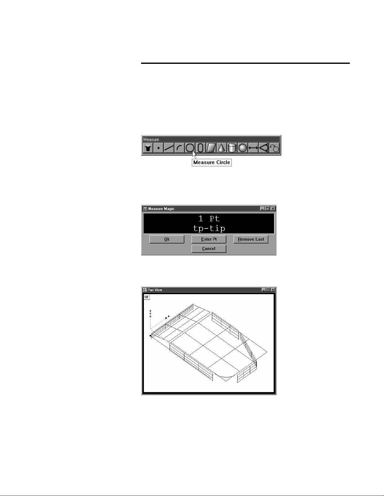
The QC5000 measures part features using the simplest geometric components: points. Lines can be created from two points, circles from three
points, and cones from six points. Simply probe the points and the
QC5000 measures the feature.
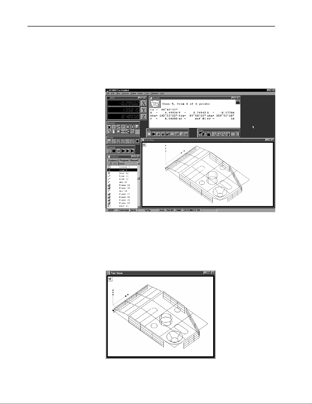
Once the required number of points are entered the QC5000 displays the
feature in the part view window.
1
Page 16
Chapter 1 Overview
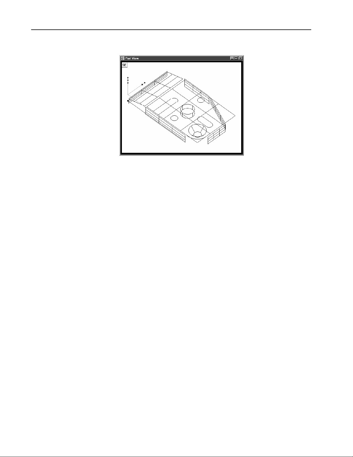
The QC5000 continues building the part in the part view window as features are added.
It is easy to use the QC5000 because each measurement requires only a few
points. All geometry and mathematics are handled by the software. Once
the basic measuring principles are understood the QC5000 can be programmed to handle repetitive measuring tasks. Finally, inspection and
quality reports can be produced to document your results.
2
Page 17

About This Guide
Quadra-Chek® 5000
This guide is intended for end users of the QC5000 metrology software,
supervisory, and installation personnel. A basic familiarity with the Windows computing environment and coordinate measuring machine (CMM)
operation is assumed. Material in this guide is divided into six chapters
covering everything from basic operation to system configuration. Keep
this guide in a convenient location for future reference.
Chapter 1: Overview
It all begins here, just point and click. There are only two things in the
QC5000 interface: windows and toolbars. This chapter tells you which is
which and what to do with them. Understanding each window and toolbar
helps you get the most from the QC5000.
Chapter 2: Quick Start
This chapter gets you up and running quickly. Use this chapter to learn the
most basic QC5000 tasks. Each task in this chapter is described in greater
detail elsewhere in this guide.
Chapter 3: Using Probes
If it’s about probes, it’s in this chapter. The probe is where the QC5000
and the coordinate measuring machine (CMM) meet. Learn proper probing techniques and you can’t go wrong.
Chapter 4: General Measuring
A solid knowledge of how to create and combine features to form a part is
essential: this chapter helps you get it. Working from the basic to the
complex, this chapter describes features and their relationships.
Chapter 5: Advanced Measuring & Output
Picking up where chapter 4 leaves off this chapter covers datum magic,
measure magic, layers, offset alignments, and tolerancing. This chapter
also describes how to export QC5000 data to other software.
Chapter 6: Templates
The QC5000 organizes and present data in a number of formats. For your
convenience there are several data templates you can use to organize and
present your results. Use this chapter to learn how to use templates more
efficiently.
Chapter 7: Programming
Programming puts it all together. This chapter shows you how to create a
streamlined, computer-prompted procedure to handle repetitive inspections with speed and accuracy. Use the programming feature to maximize
your productivity with the QC5000.
Chapter 8: System Setup & Configuration
Everything you need to setup and configure the QC5000. This final chapter gives setup procedures for shift supervisors and OEMs. End users should
apply the information in this chapter ONLY at the direction of a supervisor, distributor, or OEM.
Index
There’s nothing worse than skimming through a user guide looking for
something when you’re in a hurry. To save you the hassle we indexed this
guide. Simply flip to the back, find your topic, and off you go.
3
Page 18
Chapter 1 Overview
Icons and Type Faces
This guide uses the following icons and type faces to highlight information:
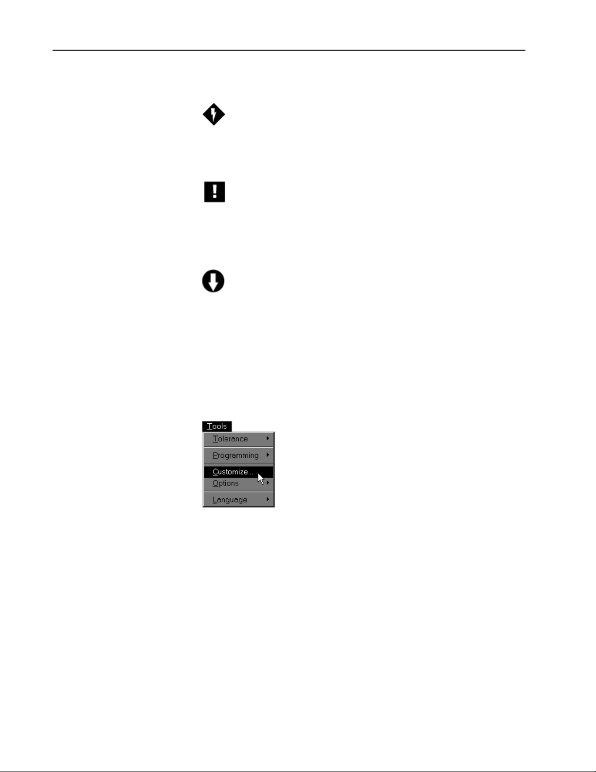
Warning
The lighting bolt icon warns of situations or conditions that can lead to
personal injury or death. Do not proceed until you read and thoroughly
understand a warning message. Warning messages are shown in bold type.
Caution
The exclamation point icon indicates situations or conditions that can lead
to measurement error, equipment malfunction or damage. Do not proceed until you read and fully understand a caution message. Caution messages are shown in bold type.
Note
The note icon indicates additional or supplementary information about an
activity or concept. Notes are shown in bold type.
Warnings, cautions, and notes are shown in this typeface.Warnings, cautions, and notes are shown in this typeface.
Warnings, cautions, and notes are shown in this typeface.
Warnings, cautions, and notes are shown in this typeface.Warnings, cautions, and notes are shown in this typeface.
Italics
Italics indicate menu items or button icons. For example,
Step 1
Select customize from the tools menu.
The italics instruct the user that customize is an item on the tools pulldown menu.
4
Page 19

Starting The QC5000
Quadra-Chek® 5000
To open the QC5000
Step 1
Double-click the QC5000 icon on the Windows NT desktop.
The following screen indicates that the program is loading. It takes a couple
seconds for the program to load completely.
5
Page 20
Chapter 1 Overview
Windows and Toolbars
The QC5000 uses a graphical user interface which means that instead of
typing in a bunch of complicated commands you can do things by pointing and clicking the mouse.
In this manual we’ll refer to the graphical user interface as the QC5000
desktop. Although setups may vary, a typical QC5000 desktop looks like
this.
There are only two things to point and click at on the QC5000 desktop:
windows and toolbars. Here’s how to tell them apart.
Windows display information. Some windows contain buttons or require
input but their basic function is to display information. For example, the
part view window displays a graphic of the part.
6
Page 21

Quadra-Chek® 5000
Toolbar contains buttons that execute common tasks. For example, the
measure toolbar contains buttons for various measurement functions. To
perform a measurement, click on the desired feature button (line, circle,
plane, etc.).
7
Page 22
Chapter 1 Overview
QC5000 Windows
The Results Window
The QC5000 desktop has four windows: DRO (digital readout), results,
part view, and features list.
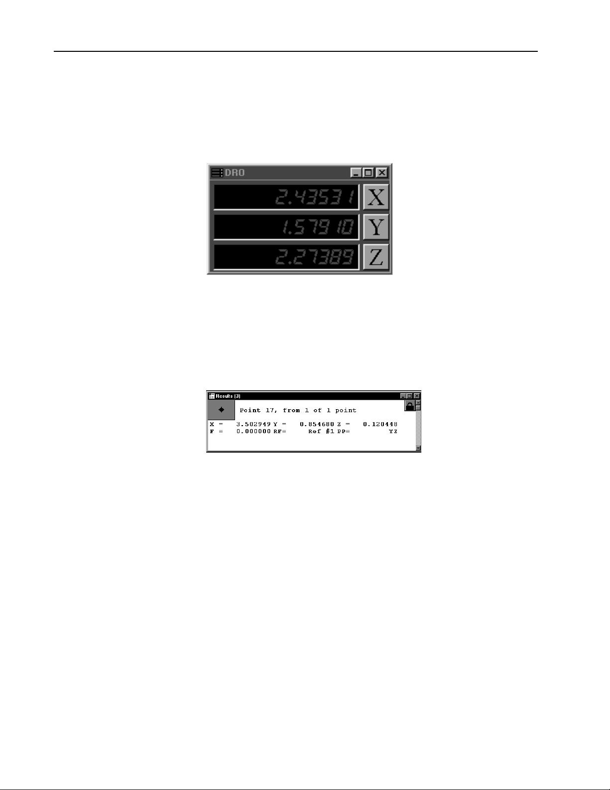
DRO
The DRO window displays the location of the X, Y, and Z axes (in mm or
inches) from the datum. Click the button beside the respective axis to zero
it.
The results window displays the results of a feature measurement. This
window contains the following:
• Feature specifications
• Lock/unlock feature
• Feature type diagram / feature stamp
Feature Specifications
Feature information is displayed in the results window. Use the results
window to add information to the features list.
8
Page 23
Quadra-Chek® 5000
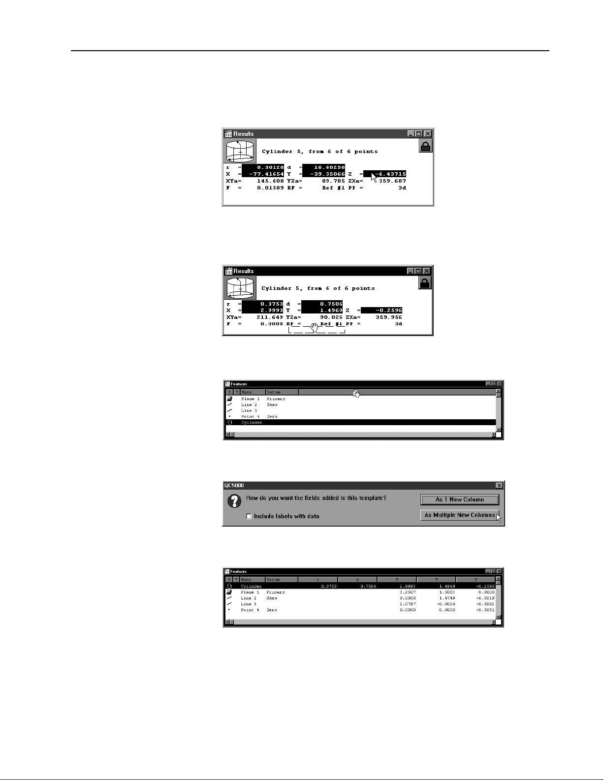
To move information from the results window to the features list
Step 1
Highlight the desired information in the results window.
Step 2
Hold down the left mouse button and drag the information to the features
list.
Step 3
Release the mouse button.
Step 4
Click the as multiple new columns button in the dialog box.
The feature window now displays the new parameters.
Information in this window is dependent on the type of feature. For example, the window shows radius/diameter values for spherical features but
not for linear ones.
9
Page 24

Chapter 1 Overview
Locked/unlocked features
Some parts use more than one reference frame to measure all its features.
Locked features are displayed in their own reference frame. Unlocked features are displayed in the current reference frame.
To unlock a feature
Step 1
Click the lock icon in the results window.
To lock a feature
Step 1
Click the lock icon in the results window.
10
Page 25
Quadra-Chek® 5000
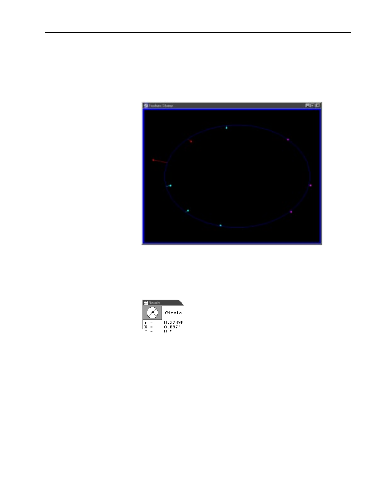
Feature type diagram /feature stamp
Clicking on the feature stamp icon opens the feature stamp window. The
feature stamp window shows a graphic display of the feature and the
distibution of the measurement points. Points discarded from the measurement are shown in red. Use the view toolbar to change the perspective
in the feature stamp window.
To open the feature stamp window
Step 1 Click the feature stamp button in the results window.
11
Page 26
Chapter 1 Overview
The Part View Window
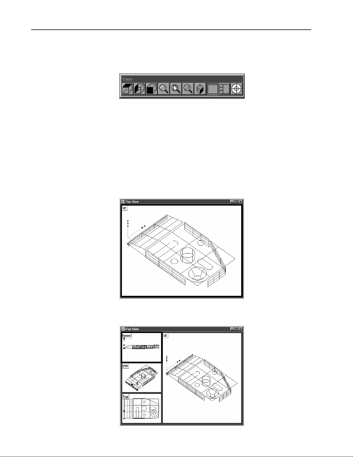
The part view window displays a graphical representation of the part and
its features. Use the view toolbar to change the appearence of the part view
window.
This is a typical view toolbar. Remember that QC5000 toolbars can be
customized. Toolbars pictured in this guide may vary from those on your
system.
Four pane part view displays the part from four separate vantage points.
Highlighted panes are outlined in blue. Place the cursor on the pane and
click to highlight. Only one pane can highlighted at a time.
The most common part view window appearences are shown here.
Single pane part view
12
Four pane part view
Page 27
View Rotator
Quadra-Chek® 5000
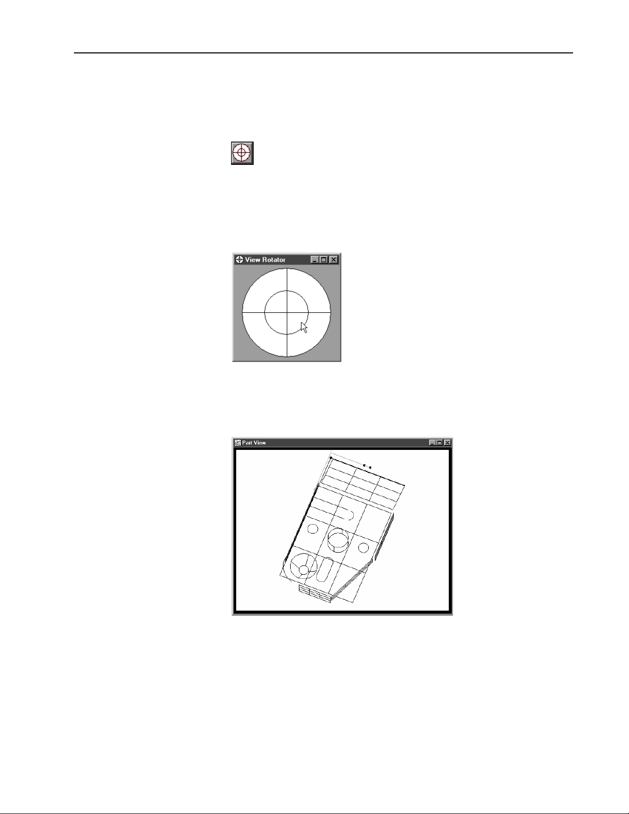
Change the display angle of the part view window with the view rotator.
To use the view rotator
Step 1
Click the view rotator button on the view toolbar OR select view rotator from the view menu..
Step 2
Place the cursor over the view rotator window as shown.
Step 3
Move the cursor over the view rotator window until the part is displayed as
desired.
13
Page 28
Chapter 1 Overview
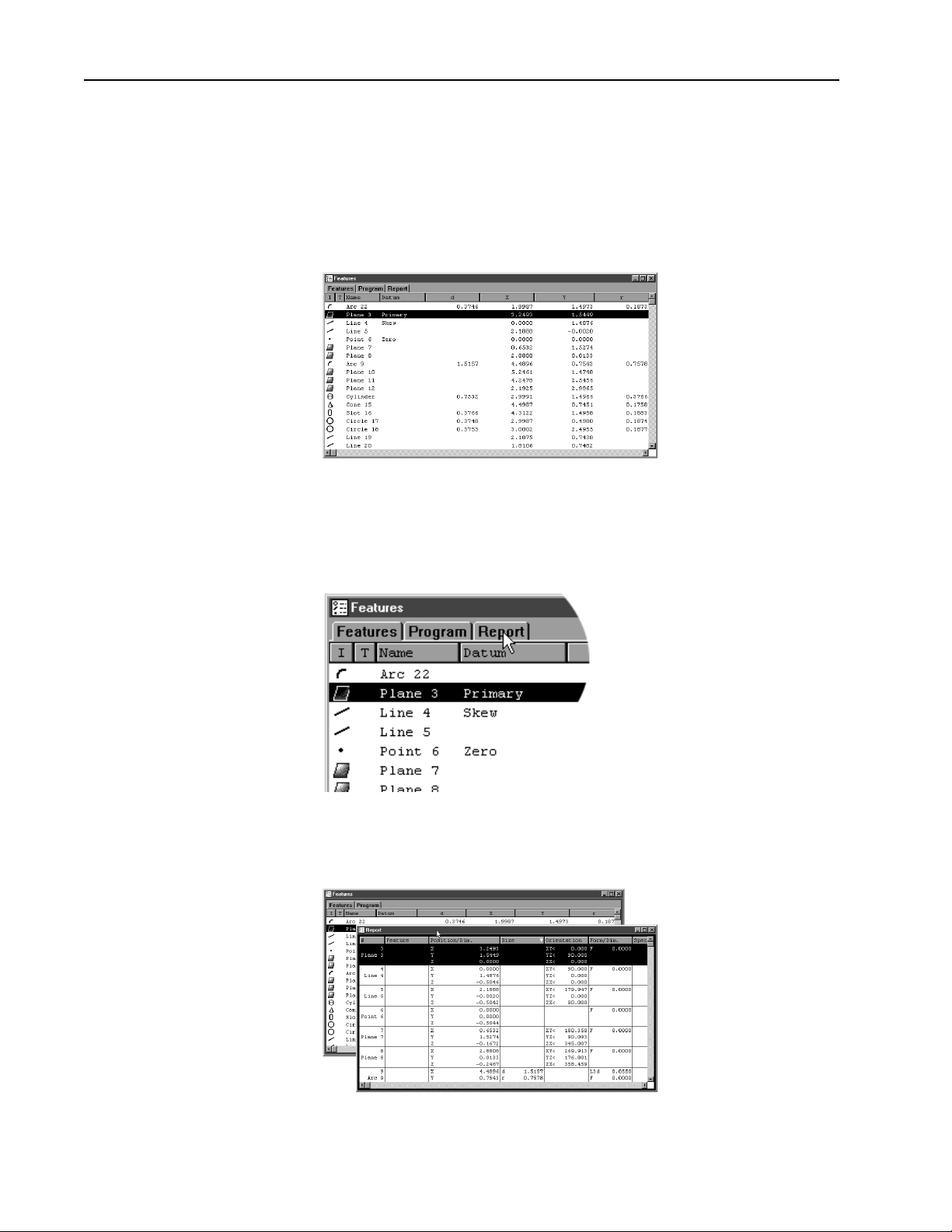
Template Windows
Template windows display data output from QC5000 measurements and
programs. See Chapter 4: Advanced Measuring & Output for more infor-
mation on using template windows.
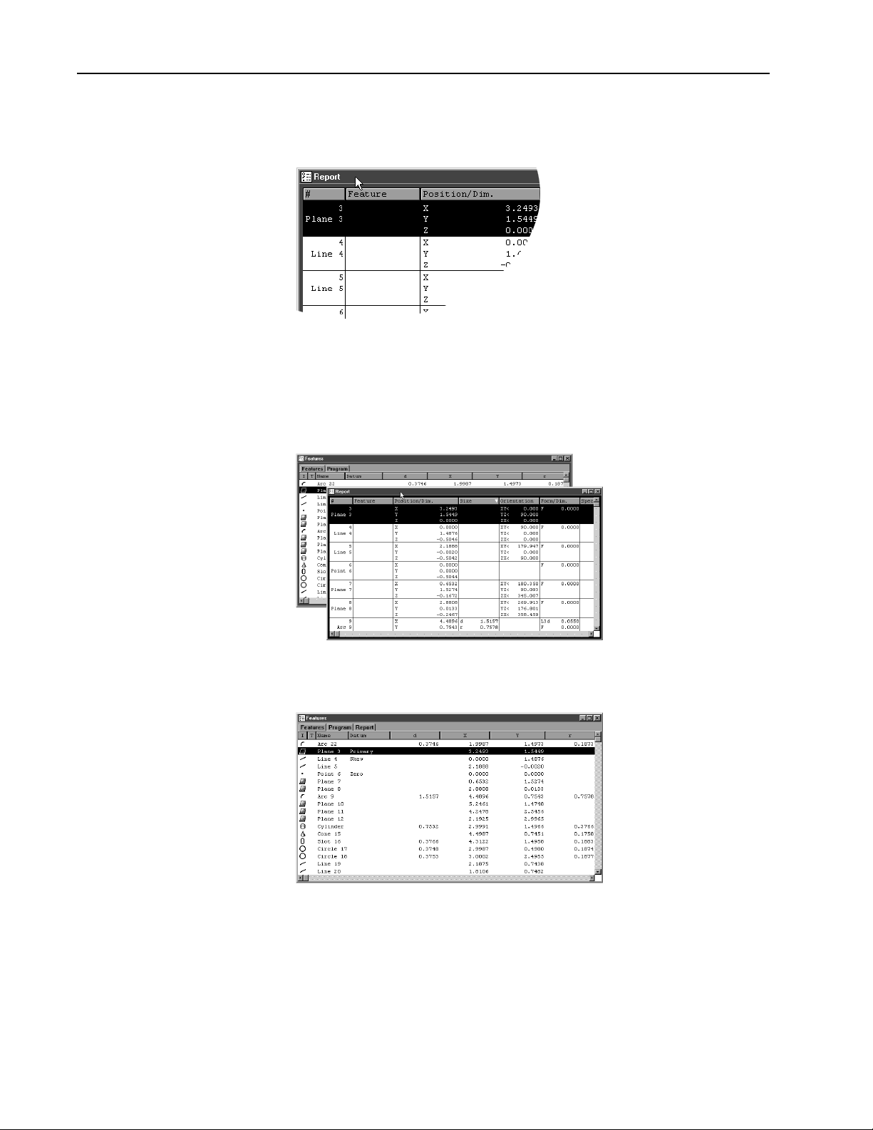
Nest templates windows as shown to conserve space on the QC5000 screen.
For example, the window below contains the features, program, and report templates nested in a single window. View the desired template by
selecting the proper tab. In the example below, the feature tab is selected.
To separate template windows
Step 1
Place the cursor over the desired tab as shown.
Step 2
Hold the left mouse button and drag the tab outside the current window
as shown.
14
Page 29
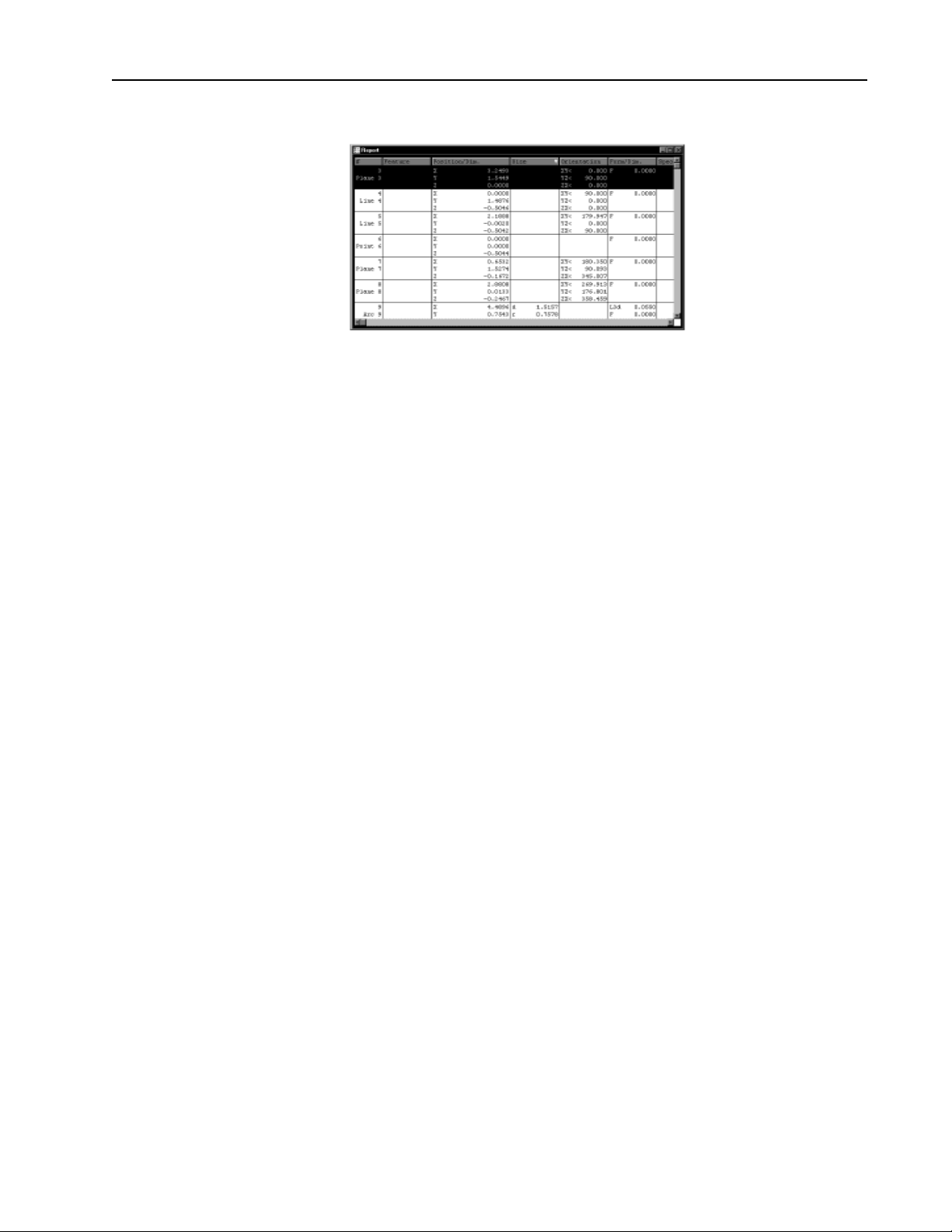
Step 3
Release the left mouse button.
Quadra-Chek® 5000
15
Page 30
Chapter 1 Overview
To nest template windows
Step 1
Place the cursor over the desired template window as shown.
Step 2
Hold the left mouse button and drag the template over the desired window.
16
Step 3
Release the mouse button.
Page 31

Status Bar
Quadra-Chek® 5000
The staus bar runs across the bottom of the screen and displays such as:
• Date
• Type of coordinates (Polar/Cartesian)
• Selected units of measurement (in./mm)
• Active Layer
• Active probe tip
• Projection Plane
• Active Reference Frame
• Angle Display Mode
• SLEC Status
• Recording or Editing Mode
Use the status bar to toggle between settings. Place the cursor over the
mm/inch section of the status bar. Click the mouse to toggle between
inches and millimeters. This is a quick way to change the units of measure.
Other settings in the status bar can be toggled in the same way.
To add items to the status bar
Step 1
Select customize from the tools menu.
Step 2
Select the status bar tab as shown.
17
Page 32

Chapter 1 Overview
Step 3
Highlight the desired item as shown.
NOTENOTE
NOTE
NOTENOTE
Items currently in the status bar have an 'X' in the box nextItems currently in the status bar have an 'X' in the box next
Items currently in the status bar have an 'X' in the box next
Items currently in the status bar have an 'X' in the box nextItems currently in the status bar have an 'X' in the box next
to them. An empty box indicates the item is currently notto them. An empty box indicates the item is currently not
to them. An empty box indicates the item is currently not
to them. An empty box indicates the item is currently notto them. An empty box indicates the item is currently not
on the status baron the status bar
on the status bar
on the status baron the status bar
Step 4
Click the show button.
..
.
..
Step 5
Click OK.
18
Page 33

To delete items from the status bar
Step 1
Select customize from the tools menu.
Step 2
Select the status bar tab as shown.
Quadra-Chek® 5000
Step 3
Highlight the desired item as shown.
NOTENOTE
NOTE
NOTENOTE
Items currently in the status bar have an 'X' in the box nextItems currently in the status bar have an 'X' in the box next
Items currently in the status bar have an 'X' in the box next
Items currently in the status bar have an 'X' in the box nextItems currently in the status bar have an 'X' in the box next
to them. An empty box indicates the item is currently notto them. An empty box indicates the item is currently not
to them. An empty box indicates the item is currently not
to them. An empty box indicates the item is currently notto them. An empty box indicates the item is currently not
on the status baron the status bar
on the status bar
on the status baron the status bar
..
.
..
19
Page 34

Chapter 1 Overview
Step 4
Click the hide button.
Step 5
Click OK.
20
Page 35

Main Menu Bar
Quadra-Chek® 5000
This section shows the content of the QC5000 pull-down menus. A
discussion of the various menu commands follows in later chapters. Use
this section to familiarize yourself with the menus. Place the cursor over
the desired menu and click to view pull-down menus.
The main menu bar contains the following pull down menus:
File
Use the file menu to access the following commands:
• New
• Open
• Save
• Save As
• Import
• Export
• DDE Output (dynamic data exchange)
• Page Setup
• Print Preview
• Print
• Exit
21
Page 36

Chapter 1 Overview
Edit
Use the edit menu to access the following commands:
• Cut
• Copy
• Paste
• Paste Special
• Delete Selection
• Select All
• Select None
• Find Features
• Change Feature
• Features Properties
View
Use the view menu to access the following commands:
• Zoom All
• Zoom Window
• Zoom Special
• Pan
• Preset View
• Set Viewpoint
• View From Probe
• View Rotator
• Show Position Indicator
• Show Reference Frame Indicator
• Layer Control
• Toolbars....
• Units
22
Page 37

Quadra-Chek® 5000
Measure
Use the measure menu to access the following commands:
• Measure Magic
• Point
• Line
• Arc
• Circle
• Slot
• Distance
• Angle
• Plane
• Cylinder
• Sphere
• Cone
• Magnetic Plane
• Other
Datum
Use the datum menu to access the following commands:
• Datum Magic
• Primary
• Secondary
• Zero
• Projection
• Magnetic Planes
• Rotate
• Reference Frame
23
Page 38

Chapter 1 Overview
Probe
Use the probe menu to access the following commands:
• Contact Probes
• Probe Compensation
• Teach
• Probe Library
• Auto Enter
Tools
Use the tools menu to access the following commands:
• Tolerance
• Programming
• Customize
• Options
• Language
Windows
Use the windows menu to access the following commands:
• DRO
• Part View
• Results
• New Template...
• Open Template...
• Save Templates As
• Features
• Program
• Report
24
Page 39

Quadra-Chek® 5000
Help
Use the help menu to access the following commands:
• What’s New?
• Backup Settings
• Restore Settings
• About QC5000
25
Page 40

Chapter 1 Overview
Toolbars
Toolbars contain buttons that execute common tasks. Use toolbars instead of hunting through pull-down menus for commands. Simply click
the desired button and the task is begun. Toolbars correspond to the main
menu. For example, buttons in the view toolbar correspond to commands
on the view menu.
Datum toolbar
Use the datum toolbar to establish datums and reference frames. Buttons
in the datum toolbar correspond to items on the datum menu.
Measure toolbar
Use the measure toolbar to measure and construct features. Buttons on the
measure toolbar correspond to items on the measure menu.
Probe toolbar
Use the probe toolbar to access probe functions and settings. Buttons on
the probe toolbar correspond to items on the probe menu.
View toolbar
Use the view toolbar to adjust the part view window. Buttons on the view
toolbar correspond to items on the view menu.
Tolerance toolbar
Use the tolerance toolbar to perform tolerances on selected features. Buttons on the tolerance toolbar correspond to items on the tools menu.
Program toolbar
Use the program toolbar to access programming functions. Buttons on the
program toolbar correspond to items on the tools menu.
File toolbar
Use the file toolbar to access file functions. Buttons on the file toolbar
correspond to items on the file menu.
26
Page 41

To place a toolbar on the QC5000 desktop
Step 1 Select toolbars from the view menu.
Step 2
Highlight the desired toolbar as shown.
Quadra-Chek® 5000
NOTENOTE
NOTE
NOTENOTE
TT
oolbars on the QC5000 desktop have an 'X' in the boxoolbars on the QC5000 desktop have an 'X' in the box
T
oolbars on the QC5000 desktop have an 'X' in the box
TT
oolbars on the QC5000 desktop have an 'X' in the boxoolbars on the QC5000 desktop have an 'X' in the box
next to them. An empty box indicates the item is currentlynext to them. An empty box indicates the item is currently
next to them. An empty box indicates the item is currently
next to them. An empty box indicates the item is currentlynext to them. An empty box indicates the item is currently
NOT on the desktop.NOT on the desktop.
NOT on the desktop.
NOT on the desktop.NOT on the desktop.
Step 3
Click the show button.
27
Page 42

Chapter 1 Overview
To remove a toolbar from the QC5000 desktop
Step 1
Select toolbars from the view menu.
Step 2
Highlight the desired toolbar as shown.
28
NOTENOTE
NOTE
NOTENOTE
TT
oolbars on the QC5000 desktop have an 'X' in the boxoolbars on the QC5000 desktop have an 'X' in the box
T
oolbars on the QC5000 desktop have an 'X' in the box
TT
oolbars on the QC5000 desktop have an 'X' in the boxoolbars on the QC5000 desktop have an 'X' in the box
next to them. An empty box indicates the item is currentlynext to them. An empty box indicates the item is currently
next to them. An empty box indicates the item is currently
next to them. An empty box indicates the item is currentlynext to them. An empty box indicates the item is currently
NOT on the desktop.NOT on the desktop.
NOT on the desktop.
NOT on the desktop.NOT on the desktop.
Step 3
Click the hide button.
Page 43

Quadra-Chek® 5000
Customize your toolbars by adding or deleting buttons. Add buttons for
common tasks . Delete seldom used buttons to keep toolbar size manageable.
To add buttons to a toolbar
Step 1
Select customize from the tools menu.
Step 2
Select the toolbars tab in the customize dialog box.
Step 3
Highlight the desired toolbar in the toolbars list as shown.
Step 4
Highlight the desired button in the all possible buttons list.
29
Page 44

Chapter 1 Overview
Step 5
Click the copy button.
Step 6
Click OK.
30
Page 45

Quadra-Chek® 5000
To remove buttons to a toolbar
Step 1
Select customize from the tools menu.
Step 2
Select the toolbars tab in the customize dialog box.
Step 3
Highlight the desired toolbar in the toolbars list as shown.
Step 4
Highlight the desired button in the buttons in toolbar list.
Step 5
Click the remove button.
31
Page 46

Chapter 1 Overview
Step 6
Click OK.
32
Page 47

Quick Start
Chapter 2
Quick Start
Use the quick start chapter to begin using the QC5000 immediately. This chapter will describe the most common user tasks associated with the QC5000.
More detailed explanations for each task are found in subsequent chapters of
this guide.
Set machine zero
Step 1
Double-click the QC5000 icon on the Windows NT desktop.
Step 2
Move the axes of the CMM to the machine zero position (consult the CMM
user guide for more information) when the dialog box appears o the screen.
Step 3
Click OK in the dialog box.
CACA
UTIONUTION
CA
UTION
CACA
UTIONUTION
Set machine zero every time you begin a QC5000 session. MachineSet machine zero every time you begin a QC5000 session. Machine
Set machine zero every time you begin a QC5000 session. Machine
Set machine zero every time you begin a QC5000 session. MachineSet machine zero every time you begin a QC5000 session. Machine
zero is used by QC5000 for SLEC (segmented linear errorzero is used by QC5000 for SLEC (segmented linear error
zero is used by QC5000 for SLEC (segmented linear error
zero is used by QC5000 for SLEC (segmented linear errorzero is used by QC5000 for SLEC (segmented linear error
correction) functions. If machine zero is not set, SLEC functionscorrection) functions. If machine zero is not set, SLEC functions
correction) functions. If machine zero is not set, SLEC functions
correction) functions. If machine zero is not set, SLEC functionscorrection) functions. If machine zero is not set, SLEC functions
will not work properlywill not work properly
will not work properly
will not work properlywill not work properly
..
.
..
33
Page 48

Chapter 2 Quick Start
Create a reference frame
Step 1
Click the primary plane button on the datum toolbar.
Step 2
Measure three points on the plane as shown.
Step 3
Click OK in the dialog box.
Step 4
Click the secondary line button on the datum toolbar.
Step 5
Probe two points on the secondary line. Space the points close to the opposite
ends of the line.
34
Page 49

Quadra-Chek® 5000
Step 6
Click OK in the dialog box.
Step 7
Click the line button on the measure toolbar.
Step 8
Probe two points along the tertiary alignment as shown.
Step 9
Click OK in the dialog box.
Step 10
Click the zero point button on the datum toolbar.
35
Page 50

Chapter 2 Quick Start
Step 11
Use the mouse to highlight the secondary and tertiary lines in the features list.
Step 12
Click OK in the dialog box.
36
Page 51

Measure a line (minimum 2 points)
Step 1
Probe two points on the line as shown.
Step 2
Click OK in the dialog box.
Quadra-Chek® 5000
Measure a circle (minimum 3 points)
Step 1
Probe three points on the circle as shown.
Step 2
Click OK in the dialog box.
37
Page 52

Chapter 2 Quick Start
Measure a cone (minimum 6 points)
Step 1
Probe six points on the cone as shown.
Step 2
Click OK in the dialog box.
38
Page 53

Measure a cylinder (minimum 6 points)
Step 1
Probe six points on the cylinder as shown.
Step 2
Click OK in the dialog box.
Quadra-Chek® 5000
39
Page 54

Chapter 2 Quick Start
Measure a distance
Step 1
Highlight two linear feature on the features list.
Step 2
Click the distance button on the measure toolbar.
Step 3
Click OK in the dialog box.
40
Page 55

Quadra-Chek® 5000
Save a part file
Step 1
Select save as from the file menu.
Step 2
Type a name for the part file in the file name text box in the dialog box.
Step 3
Select a storage location for the file using the folders box and/or drives box.
41
Page 56

Chapter 2 Quick Start
Step 4
Click OK in the dialog box.
42
Page 57

Probing Technique
Probe Toolbar
Chapter 3
Using Probes
Probing technique refers to the method of moving CMM axes and entering
point data with a touch probe. All features are made up of points and all points
are taken with probes. In order to get good results from the QC5000 software
it is important to use proper probe technique and to input proper probe settings.
Good probing techniques
• approach the feature from a 90 degree angle
• approach the feature from a distance of at least 1mm
• do not probe a feature from an angle of 45 degrees or less
Bad probing techniques
• dragging probe across a part
• dropping probe off the edge of a part
The probe toolbar contains several buttons for intitiating probe functions.
• Probe teach
• Probe compensation
• Cardinal probe compensation
• Polar probe compensation
• Auto enter
• Probe library
Probe teach
Click the probe teach button to begin the calibration of a probe tip.
Probe compensation off
Click the probe compensation button to toggle off probe compensation.
43
Page 58

Chapter 3 Using Probes
Cardinal probe compensation
Click the cardinal probe compensation button to toggle on/off probe cardinal
compensation. Use cardinal probe compensation for general measuring of features to apply compensation for the probe tip radius in the probe direction.
Polar probe compensation
Click the polar probe compensation button to toggle on/off polar probe compensation. Use polar probe compensation for probing point features in polar
coordinate mode.
Auto enter
Click the auto enter icon to toggle on/off auto enter. Use auto enter to automatically enter a point from a touch probe upon contact.
Probe library
Click the probe library button to access the probe library window.
44
Page 59

Probe compensation
Quadra-Chek® 5000
Use the probe compensation feature to allow for less than perfect probe technique. It is simple enough to use good probe technique when measuring flat
features. Features on angled surfaces are more difficult.
Since perfect technique is difficult to achieve even on flat surfaces use probe
compensation all measurements. Probe compensation makes up for less than
perfect probe technique; it does not make up for bad probe technique.
Click the probe compensation button on the probe toolbar to toggle on/off
probe compensation. Probe compensation is the amount of offset applied for
the diameter of the probe tip. The direction compensation is applied is determined by the direction the probe travels immediately before taking a point.
Probe compensation off
Click the probe compensation button to toggle off probe compensation. Use
porbe compensation off to turn off probe or cardinal compensation.
Cardinal probe compensation
Click the cardinal probe compensation button to toggle on/off probe cardinal
compensation. Use cardinal probe compensation for general measuring of features to apply compensation for the probe tip radius in the probe direction.
Polar probe compensation
Click the polar probe compensation button to toggle on/off polar probe compensation. Use polar probe compensation for probing point features in polar
coordinate mode.
45
Page 60

Chapter 3 Using Probes
To activate probe compensation
Step 1
Click the polar or cardinal probe compensation button on the probe toolbar.
OR
Step 1
Select probe compensation from the probes menu.
Step 2
Select cardinal or polar from the submenu as shown.
46
Page 61

Auto Enter
Quadra-Chek® 5000
The simplest way to enter points is to use Auto Enter. Auto Enter records each
probe hit as a point. This allows point entry without keyboard, mouse, or
footswitch input after each probe hit.
NOTENOTE
NOTE
NOTENOTE
Auto Enter does not work with hard probes.Auto Enter does not work with hard probes.
Auto Enter does not work with hard probes.
Auto Enter does not work with hard probes.Auto Enter does not work with hard probes.
To activate auto enter
Step 1
Click the auto enter button on the probe toolbar.
NOTENOTE
NOTE
NOTENOTE
Probe Library
auto enterauto enter
The The
auto enter
The
auto enterauto enter
The The
while activated.while activated.
while activated.
while activated.while activated.
OR
Step 1
Select auto enter from the probes menu.
NOTENOTE
NOTE
NOTENOTE
A check-mark appears next to auto enter on the menu whenA check-mark appears next to auto enter on the menu when
A check-mark appears next to auto enter on the menu when
A check-mark appears next to auto enter on the menu whenA check-mark appears next to auto enter on the menu when
active.active.
active.
active.active.
Probe library organizes all the probes used with the QC5000 software. Use
probe library to set up and manage probes and probe settings.
button remains depressed on the probe toolbar button remains depressed on the probe toolbar
button remains depressed on the probe toolbar
button remains depressed on the probe toolbar button remains depressed on the probe toolbar
Probe set up functions include
• creating probe groups
• designating a master probe
Management functions include
• storing reference offset data
• storing probe qualification data
• adding/deleting probes from groups
47
Page 62

Chapter 3 Using Probes
Probe Families & Groups
Click the tool library button on the probe toolbar to view the tool library dialog
box. Probes are organized into families and groups. Families consist of groups.
Groups consist of probes.
Probe families organize similar probe groups. For example, the contact probes
family contains the groups: HardProbe, TouchProbe, StarProbe.
NOTENOTE
NOTE
NOTENOTE
QC5000 metrology software for manual CMMs uses only theQC5000 metrology software for manual CMMs uses only the
QC5000 metrology software for manual CMMs uses only the
QC5000 metrology software for manual CMMs uses only theQC5000 metrology software for manual CMMs uses only the
contact probes familycontact probes family
contact probes family
contact probes familycontact probes family
Click on the plus (+) sign next to the contact probes family.
. New probe families cannot be created.. New probe families cannot be created.
. New probe families cannot be created.
. New probe families cannot be created.. New probe families cannot be created.
Observe the three default probe groups: HardProbe, TouchProbe, StarProbe.
HardProbe group
Hard probes have no internal switching mechanism to detect contact with the
part. User simply position a hard probe in contact with the part and manually
enters the point.
48
Page 63

Quadra-Chek® 5000
TouchProbe group
Touch probes have an internal switch that sends an electronical signal when the
probe contacts the part. This electronic signal allows the auto-enter feature of
the QC5000 to automatically enter the point.
StarProbe group
Star probes are actually a variant of touch probes. Each star probes have five tips
arranged bottom, left, right, front, and back. These tips appear by default in the
StarProbe group.
49
Page 64

Chapter 3 Using Probes
To create a new probe group
Step 1
Highlight the desired probe family for the new group.
Step 2
Click on the new button.
Step 3
Type a name for the group in the name text box.
50
Step 4
Check the auto change box for probes interchangeable with other groups. If
using an indexable or friction probe check the appropriate box otherwise proceed to step 4.
Step 4
Enter the distance the probe must travel in a direction prior to making contact
with the part in the probe direction distance text box.
Page 65

Quadra-Chek® 5000
NOTENOTE
NOTE
NOTENOTE
Probe direction distance determines in which direction probeProbe direction distance determines in which direction probe
Probe direction distance determines in which direction probe
Probe direction distance determines in which direction probeProbe direction distance determines in which direction probe
compensation is applied.compensation is applied.
compensation is applied.
compensation is applied.compensation is applied.
51
Page 66

Chapter 3 Using Probes
Probe Calibration
There are two factors that influence probe measurements: the radius of the probe
tip and the spatial (X, Y, and Z) position of the probe tip. All measurements are
based on the location of the center of the probe tip. Probe compensation applies a calculation to correct for the radius of the probe on each measurement.
The compensation for each probe tip is calculated automatically when the probe
is taught.
Click on the TouchProbe group and observe the probes in the right-hand data
box. The following information appears in the probe data box by default name
of the probe, date of probe qualification, and the name of the person who performed the qualification.
NOTENOTE
NOTE
NOTENOTE
The date and the name of the person qualifying the probe areThe date and the name of the person qualifying the probe are
The date and the name of the person qualifying the probe are
The date and the name of the person qualifying the probe areThe date and the name of the person qualifying the probe are
taken from the Windows system clock and login respectivelytaken from the Windows system clock and login respectively
taken from the Windows system clock and login respectively
taken from the Windows system clock and login respectivelytaken from the Windows system clock and login respectively
..
.
..
Probe qualification, or probe teaching, refers to the process of establishing the
dimension of the probe tip. This process typically involves taking a number of
probe hts on a qualification sphere with a known diameter. Qualifying, or
teaching, a probe also provides offsets for probe compensation.
Master probe tips
Teaching a probe also establishes the spatial (X, Y, and Z) position of the probe
tip (master probe tip) or the X,Y, and Z offsets (non-master tips) from the master tip. Each probe group has one master probe tip. The X, Y, and Z values of
each probe in a group is compared to the master probe. The difference becomes
the X, Y, and Z offset value for each non-master probe tip.
For example, a star probe group has five probe tips: one master tip and four
non-master tips. The X, Y, and Z position on the non-master tips are all calculated by their X, Y, and Z offset from the master tip. Since the tips on a star
probe are fixed and repeatable simply re-teaching the master tip is sufficient to
update the entire group.
The same holds true for index probes that can be moved into various repeatable
positions. Each position can be entered into probe library as a new tip. Establishing one position as the master tip allows all the non-master tips (positions)
to update when the master tip is re-taught.
52
Page 67

To teach (qualify) a master probe tip
Step 1
Highlight the desired probe as shown.
Step 2
Check the reference offset checkbox as shown.
Step 3
Click on the teach button.
Quadra-Chek® 5000
Step 4
Probe the qualification sphere as shown.
NOTENOTE
NOTE
NOTENOTE
4 points are the minimum required for a sphere measurement.4 points are the minimum required for a sphere measurement.
4 points are the minimum required for a sphere measurement.
4 points are the minimum required for a sphere measurement.4 points are the minimum required for a sphere measurement.
Use more points to increase the accuracy of your measurements.Use more points to increase the accuracy of your measurements.
Use more points to increase the accuracy of your measurements.
Use more points to increase the accuracy of your measurements.Use more points to increase the accuracy of your measurements.
Step 5
Click OK in the dialog box.
53
Page 68

Chapter 3 Using Probes
To teach (qualify) a non-master probe tip
Step 1
Highlight the desired probe as shown.
Step 2
Click the teach button.
Step 3
Probe the qualification sphere as shown.
54
NOTENOTE
NOTE
NOTENOTE
4 points are the minimum required for a sphere measurement.4 points are the minimum required for a sphere measurement.
4 points are the minimum required for a sphere measurement.
4 points are the minimum required for a sphere measurement.4 points are the minimum required for a sphere measurement.
Use more points to increase the accuracy of your measurements.Use more points to increase the accuracy of your measurements.
Use more points to increase the accuracy of your measurements.
Use more points to increase the accuracy of your measurements.Use more points to increase the accuracy of your measurements.
Step 4
Click OK in the dialog box.
Page 69

Changing Probes
Quadra-Chek® 5000
There are a number of ways to select different probes. This section shows how
to view available probes, change probes, and add/delete probes.
To view the probes in a group
Step 1
Click the probe library button on the probe toolbar.
Step 2
Click on the plus sign to view the groups in the family.
To change the current probe tip
Step 1
Click the probe library button on the probe toolbar.
Step 2
Click on the plus sign next to the desired group in the left-hand box.
Step 3
Highlight the desired group.
55
Page 70

Chapter 3 Using Probes
Step 4
Highlight the new probe tip as shown.
Step 5
Click the set current button
Step 6
Click OK.
OR
Step 1
Place the cursor over the status bar as shown.
Step 2
Click until the desired probe appears in the status bar.
56
Page 71

To add probe tips
Step 1
Click the probe library button on the probe toolbar.
Step 2
Highlight the desired group.
Step 3
Click the new button.
Quadra-Chek® 5000
Step 4
Type a name for the probe tip in the name text box.
Step 5
Select the appropriate probe type from the pull down list.
57
Page 72

Chapter 3 Using Probes
Step 7
Check the show this probe in the probe menu box.
Step 8
Click OK.
58
Page 73

Quadra-Chek® 5000
To delete probe tips
Step 1
Click the probe library button on the probe toolbar.
Step 2
Click on the plus sign next to the desired group in the left-hand box.
Step 3
Highlight the probe tip to be deleted.
Step 4
Click on the delete button.
Step 5
Click yes in the dialog box.
NOTENOTE
NOTE
NOTENOTE
The QC5000 does not permit the probe in current use to beThe QC5000 does not permit the probe in current use to be
The QC5000 does not permit the probe in current use to be
The QC5000 does not permit the probe in current use to beThe QC5000 does not permit the probe in current use to be
deleted. The current can be deleted only after a new probe tip isdeleted. The current can be deleted only after a new probe tip is
deleted. The current can be deleted only after a new probe tip is
deleted. The current can be deleted only after a new probe tip isdeleted. The current can be deleted only after a new probe tip is
assigned as current.assigned as current.
assigned as current.
assigned as current.assigned as current.
59
Page 74

Chapter 3 Using Probes
Probe Results Window
The results window displays the following information for probe qualification
• X,Y,Z offsets (measured from the center of the probe)
• probe diameter
• form (a numerical representation of the deviance from the nominal form)
• qualification sphere diameter
NOTENOTE
NOTE
NOTENOTE
The qualification results window is a view only windowThe qualification results window is a view only window
The qualification results window is a view only window
The qualification results window is a view only windowThe qualification results window is a view only window
information can be dragged into other windows from theinformation can be dragged into other windows from the
information can be dragged into other windows from the
information can be dragged into other windows from theinformation can be dragged into other windows from the
qualification results windowqualification results window
qualification results window
qualification results windowqualification results window
NOTENOTE
NOTE
NOTENOTE
If the F (form) value shown in the If the F (form) value shown in the
If the F (form) value shown in the
If the F (form) value shown in the If the F (form) value shown in the
re-teach the probe. In general, an re-teach the probe. In general, an
re-teach the probe. In general, an
re-teach the probe. In general, an re-teach the probe. In general, an
resolution of the encoders is considered large. Fresolution of the encoders is considered large. F
resolution of the encoders is considered large. F
resolution of the encoders is considered large. Fresolution of the encoders is considered large. F
valuevalue
of 3 microns is large if using 2 micron encoders. of 3 microns is large if using 2 micron encoders.
value
of 3 microns is large if using 2 micron encoders.
valuevalue
of 3 microns is large if using 2 micron encoders. of 3 microns is large if using 2 micron encoders.
..
.
..
probe resultsprobe results
probe results
probe resultsprobe results
F valueF value
F value
F valueF value
window is large window is large
window is large
window is large window is large
larger than the larger than the
larger than the
larger than the larger than the
or example, an or example, an
or example, an
or example, an or example, an
. No. No
. No
. No. No
FF
F
FF
60
Page 75

Quadra-Chek® 5000
61
Page 76

Chapter 3 Using Probes
62
Page 77

Getting Started
Chapter 4
General Measuring
Set machine zero
Machine zero is the location where all three axes of the coordinate measuring
machine (CMM) read zero. This is an arbitrary point usually selected because it
is at the end of negative travel for each axis. Since the machine zero position can
vary from machine to machine, consult the distributor or manufacturer information for the specific procedure.
To set machine zero
Step 1
Double-click the QC5000 icon on the Windows NT desktop.
Step 2
Move the axes of the CMM to the machine zero position (consult the CMM
user guide for more information) when the dialog box appears o the screen.
Step 3
Click OK in the dialog box.
63
Page 78

Chapter 4 General Measuring
Use the following procedure if the QC5000 software is alreadyUse the following procedure if the QC5000 software is already
Use the following procedure if the QC5000 software is already
Use the following procedure if the QC5000 software is alreadyUse the following procedure if the QC5000 software is already
running and machine zero is not set.running and machine zero is not set.
running and machine zero is not set.
running and machine zero is not set.running and machine zero is not set.
Step 1
Select options, then general options, from the tools menu.
Step 2
Select the general tab in the general options window.
NOTENOTE
NOTE
NOTENOTE
64
NOTENOTE
NOTE
NOTENOTE
If the general tab is greyed out, enter the supervisor passwordIf the general tab is greyed out, enter the supervisor password
If the general tab is greyed out, enter the supervisor password
If the general tab is greyed out, enter the supervisor passwordIf the general tab is greyed out, enter the supervisor password
on the supervisor tab.on the supervisor tab.
on the supervisor tab.
on the supervisor tab.on the supervisor tab.
Page 79

Step 3
Select hard stop in the machine zero box.
Step 4
Click the set now button.
Quadra-Chek® 5000
Step 5
Move the axes of the CMM to the machine zero position (consult the CMM
user guide for more information) when the dialog box appears o the screen.
Step 6
Click OK in the dialog box.
65
Page 80

Chapter 4 General Measuring
Step 7
Click OK in the general options window.
Set machine zero every time you begin a QC5000 session. MachineSet machine zero every time you begin a QC5000 session. Machine
Set machine zero every time you begin a QC5000 session. Machine
Set machine zero every time you begin a QC5000 session. MachineSet machine zero every time you begin a QC5000 session. Machine
zero is used by QC5000 for SLEC (segmented linear errorzero is used by QC5000 for SLEC (segmented linear error
zero is used by QC5000 for SLEC (segmented linear error
zero is used by QC5000 for SLEC (segmented linear errorzero is used by QC5000 for SLEC (segmented linear error
correction) functions. If machine zero is not set, SLEC functionscorrection) functions. If machine zero is not set, SLEC functions
correction) functions. If machine zero is not set, SLEC functions
correction) functions. If machine zero is not set, SLEC functionscorrection) functions. If machine zero is not set, SLEC functions
will not work properlywill not work properly
will not work properly
will not work properlywill not work properly
CACA
CA
CACA
UTIONUTION
UTION
UTIONUTION
..
.
..
66
Page 81

Quadra-Chek® 5000
Reference Frame
Parts are made up of features. Features are made up of points. Points are locations within the measuring envelope of the CMM. The measuring envelope is
the area of the CMM that can be reached by the probe.
The machine coordinate system defines all the points in the measuring envelope
starting a machine zero. Machine zero is the beginning of positive travel on
each axis.
67
Page 82

Chapter 4 General Measuring
Projection planes
A projection plane is the lateral extension of one axis along another axis in the
machine coordinate system.
For example, the XY plane is the lateral extension of the X axis along the Y axis.
Machine coordinates
Machine coordinates describe the distance of points within the measuring envelope from machine zero. Until a reference frame is created the QC5000 displays
machine coordinates in the DRO window. Once a reference frame is established the DRO display part coordinates.
Part coordinates
Part coordinates describe the distance of points from the datum, or zero point,
of the reference frame. Reference frames are created by probing a primary plane,
a secondary line, and a zero point.
NOTENOTE
NOTE
NOTENOTE
Set machine zero before establishing a reference frame and beSet machine zero before establishing a reference frame and be
Set machine zero before establishing a reference frame and be
Set machine zero before establishing a reference frame and beSet machine zero before establishing a reference frame and be
sure the current probe is qualified.sure the current probe is qualified.
sure the current probe is qualified.
sure the current probe is qualified.sure the current probe is qualified.
68
Page 83

To create a reference frame
Step 1
Click the primary plane button on the datum toolbar.
Step 2
Measure three points on the plane as shown.
Step 3
Click OK in the dialog box.
Quadra-Chek® 5000
Step 4
Click the secondary line button on the datum toolbar.
Step 5
Probe two points on the secondary line. Space the points close to the opposite
ends of the line.
69
Page 84

Chapter 4 General Measuring
Step 6
Click OK in the dialog box.
Step 7
Click the line button on the measure toolbar.
Step 8
Probe two points along the tertiary alignment as shown.
Step 9
Click OK in the dialog box.
Step 10
Click the zero point button on the datum toolbar.
70
Page 85

Quadra-Chek® 5000
Step 11
Use the mouse to highlight the secondary and tertiary lines in the features list.
Step 12
Click OK in the dialog box.
71
Page 86

Chapter 4 General Measuring
Measuring 2D Features
To probe a point
Step 1
Click the point button on the measure toolbar.
Step 2
Probe the point as shown.
Step 3
Click OK in the dialog box.
72
Page 87

Quadra-Chek® 5000
To probe a line (2 points)
Step 1
Click the line button on the measure toolbar.
Step 2
Probe two points on the line as shown. Space the points close to the opposite
ends of the line.
Step 3
Click OK in the dialog box.
73
Page 88

Chapter 4 General Measuring
To probe an arc (3 points)
Step 1
Click the arc button on the measure toolbar.
Step 2
Probe three points on the arc in the order shown.
Step 3
Click OK in the dialog box.
74
Page 89

To probe a circle (3 points)
Step 1
Click the circle button on the measure toolbar.
Step 2
Probe a point on the edge of the circle
Quadra-Chek® 5000
Step 3
Probe the second point approximately 120 degrees from the first point.
Step 4
Probe the third point approximately 120 degrees from the second point.
Step 5
Click OK in the dialog box.
75
Page 90

Chapter 4 General Measuring
To probe a slot (5 points)
Step 1
Click the slot button on the measure toolbar.
Step 2
Probe the first two points as shown.
Step 3
Probe a point, as near the center as possible, on the first arc.
Step 4
Probe a point near the middle of the second side of the slot.
Step 5
Probe a point, as near the center as possible, on the second arc.
Step 6
Click OK in the dialog box.
76
Page 91

To probe a plane (3 points)
Step 1
Click the plane button on the measure toolbar.
Step 2
Measure three points on the plane as shown.
Quadra-Chek® 5000
Step 3
Click OK in the dialog box.
77
Page 92

Chapter 4 General Measuring
Measuring 3D Features
To probe a cone (3 points)
Step 1
Click the cone button on the measure toolbar.
Step 2
Probe three points around the top of the cone spacing the points evenly as shown.
Step 3
Probe three points around the bottom of the cone spacing the points evenly as
shown.
Step 4
Click OK in the dialog box.
78
Page 93

Quadra-Chek® 5000
To probe a cylinder (6 points)
Step 1
Click the cylinder button on the measure toolbar.
Step 2
Probe 3 points around the top of the cylinder spacing the points evenly as shown.
Step 3
Probe 3 points around the bottom of the cylinder spacing the points evenly as
shown.
Step 4
Click OK in the dialog box.
79
Page 94

Chapter 4 General Measuring
To probe a sphere (5 points)
Step 1
Click the sphere button on the measure toolbar.
Step 2
Probe a point on the top of the sphere as shown.
Step 3
Probe 3 points around the equator of the sphere as shown.
Step 4
Click OK in the dialog box.
80
Page 95

Constructing Features
Point Constructions
Quadra-Chek® 5000
It is sometimes useful to construct a new feature from existing features. This
section demonstrates all feature constructions.
To construct a center point
Step 1
Use the mouse to highlight a slot, circle, or other positional feature on the features list.
Step 2
Click point button on the measure toolbar.
Step 3
Click OK in the dialog box.
81
Page 96

Chapter 4 General Measuring
To construct an apex point
Step 1
Use the mouse to highlight a cone or an angle on the features list.
Step 2
Click the point button on the measure toolbar.
Step 3
Click OK in the dialog box.
82
Page 97

Quadra-Chek® 5000
To construct an application point
Step 1
Use the mouse to highlight a linear feature or plane on the features list.
Step 2
Click the point button on the measure toolbar.
Step 3
Click OK in the dialog box.
83
Page 98

Chapter 4 General Measuring
To construct an anchor point
Step 1
Use the mouse to highlight a linear feature on the features list.
Step 2
Click the point button on the measure toolbar.
Step 3
Click OK in the dialog box.
Step 4
Right click in the results window and select anchor point from the list.
84
Page 99

Quadra-Chek® 5000
To construct bounding points
Step 1
Use the mouse to highlight a linear feature on the features list.
Step 2
Click the point button on the measure toolbar.
Step 3
Click OK in the dialog box.
Step4
Right click in the results window and select endpoint 1 (top) or endpoint 2(bottom) from the list.
85
Page 100

Chapter 4 General Measuring
To construct a point from 2 intersecting lines
Step 1
Use the mouse to highlight two intersecting lines on the features list.
Step 2
Click the point button on the measure toolbar.
Step 3
Click OK in the dialog box.
86
 Loading...