

Page 1
Addendum
IK 5000
QUADRA-CHEK
Software Version
3.0.x
English (en)
12/2013
Page 2

Page 3

Information contained in this manual
This addendum covers the operating and setup feature additions and improvements implemented in IK 5000 Software v3.0.x.
For OEM setup feature additions refer to the IK 5000 QUADRA-CHEK OEM Addendum (ID 1041353-2x), available by request
from HEIDENHAIN.
Minimum system requirements
Component w/o 3D Profiling w/ 3D Profiling
PC 2.66 GHz dual-core Pentium 2.8 GHz quad-core Pentium
Operating System (OS) Windows XP
Windows Vista 32-bit
Windows 7 32-bit, Windows 7 64-bit
Windows 8 32-bit, Windows 8 64-bit
RAM 1GB 2GB
Available Hard Disk 500MB 1GB
PCI 1 PCI slot and 1 to 3 additional empty slots (depending on the version)
Note: PCI Express slot required for PC2-COMP Express frame grabber board, refer to "PC2-
COMP Express frame grabber board on page 80”. The PC2-COMP Express frame grabber
board is compatible with 32-bit operating systems only.
Video Display Unit 1024 x 768 resolution
Windows users rights Administrator
Backward compatibility
The IK 5000 QUADRA-CHEK v3.0.x software version is compatible with several previous versions down to version 2.93.0. It
can be used to update any prior version starting at version 2.93.0 and up. To update a previous version refer to “Software
Updates” below.
Software updates
End users should only update the IK 5000 software after consultation with the machine manufacturer. Observe the system
requirements as described in “Minimum System Requirements” above. For software updating procedures, refer to " Updating
the IK 5000 software on page 78”.
Fonts used in these instructions
Items of special interest or concepts that are emphasized to the user are shown in bold type.
Software controls and Windows are shown in letter gothic bold type.
IK 5000 QUADRA-CHEK 3
Page 4

4 Preface
Page 5

1 Operation ..... 9
1.1 Operation ..... 10
Adjusting for change of part size ..... 10
Part scaling example ..... 11
Auto probe a plane ..... 12
Grid pattern auto probe ..... 12
Disc pattern auto probe ..... 13
Programming changes ..... 14
Programming wizards ..... 15
Grids ..... 15
Polar grids ..... 19
Palletize ..... 21
Random placement ..... 24
Additional tolerance check Axial Runout for Plane feature ..... 34
Palletizing multiple parts ..... 35
Profile import points ..... 36
Measuring rectangles ..... 38
Profile3D measurements ..... 39
Profile3D measurement screen functions ..... 40
Profile3D window menu ..... 41
The Profile3D measurement process ..... 42
Start Profile3D measurement ..... 43
Import part profile ..... 43
Enable or prohibit data shifts for Profile3D fit ..... 45
Assign tolerances ..... 46
Probe part surfaces ..... 48
Perform Profile3D fit analysis ..... 49
Profile3D automatic fit analysis ..... 50
Profile3D Pass Only option ..... 51
Six point alignment ..... 52
Resetting the fit analysis ..... 53
Adjust the display magnification of error whiskers ..... 54
Add Profile3D feature to the Feature template ..... 55
IK 5000 QUADRA-CHEK 5
Page 6

Auto Focus (option) ..... 57
Autofocus final check ..... 60
Exploding the Data Cloud ..... 61
Rotating and positioning of VED tools using part reference frame ..... 62
ISO Tolerance ..... 62
Continuous probe firing ..... 66
Programming continuous probe firing ..... 67
Initial settings step ..... 67
Program step ..... 68
Measure shortcuts ..... 69
Ellipse shortcut ..... 69
Torus shortcut ..... 69
Profile shortcut ..... 69
Profile3D shortcut ..... 69
Symmetry tolerance ..... 70
Symmetry tolerance applied to a line ..... 70
Symmetry tolerance applied to a plane ..... 72
Plane probing technique ..... 74
6
Page 7

2 Setup ..... 77
2.1 Setup ..... 78
Updating the IK 5000 software ..... 78
Files and folders ..... 79
PC2-COMP Express frame grabber board ..... 80
Use current reference frame ..... 81
Camera parameters ..... 83
Specify video probe parameters ..... 84
Spotter camera options ..... 85
Scale factor for Open Loop joystick control (Optional) ..... 87
Shutdown ..... 89
Debounce parameters ..... 90
Touch probe requalification and starting point ..... 91
Reset template text colors ..... 92
Default fixtures files location ..... 93
External amplifier Open Loop control (Optional) ..... 94
Backup system settings ..... 78
Uninstall old software version ..... 78
Install new software version ..... 78
Restore system settings ..... 78
Joystick button assignment ..... 95
IK 5000 QUADRA-CHEK 7
Page 8

8
Page 9

Operation
Page 10
1.1 Operation
Adjusting for change of part size
The location of features in a part under measure can change due to
change in size of the part. A program can adjust to measure the
features at the new locations by using the Prompt user for part scaling
function. This function prompts the user for a scaling factor that
repositions all features in a program. The new feature position is
1.1 Operation
calculated using the recorded feature position multiplied by the scaling
factor. The scaling factor is prompted for each time the program is run.
The Prompt user for part scaling function is located in the General tab
of the Program Properties dialog.
The size of the features under measure in the program are
not altered by the part scaling function, hence the system
will probe the features at the recorded size but new scaled
position.
To prompt a user for part scaling:
Start recording a program
Double click Program Properties in the Program template window
Click the General tab
Check the check box next to Prompt user for part scaling and
then click OK
The operator will now be prompted to enter a scaling factor when the
program is run.
Selecting Prompt User for Part Scaling
10 1 Operation
Page 11
Part scaling example
This example shows measurement results before and after part
scaling has been applied.
Start recording a program
Measure a feature and note the position of the feature
Feature measurement results
Stop recording the program
Activate Prompt user for part scaling as described on page 10.
Run the recorded program. A prompt will appear requiring the user
to enter a part scaling factor.
1.1 Operation
Enter Part Scaling prompt
Re-measure the feature and complete program execution
Note that the program feature CIRCLE 2 will now be probed at a
position scaled by a factor of 0.500 (X=4.00000, Y=2.50000,
Z=0.00000)
IK 5000 QUADRA-CHEK 11
Page 12

Auto probe a plane
1
345
2
Plane measurement accuracy is increased by probing more than the
three required points. IK 5000 systems with CNC and touch probe
options can automatically probe multiple points by using the
Auto Probe Plane feature in the Measure Plane Dialog.
To auto probe a plane:
Click the Auto Probe... button in the Measure Plane dialog.The
Auto Probe Plane dialog appears.
1.1 Operation
Select the Grid or DISC tab
Probe the required positions and enter the required parameters
Click OK
Grid pattern auto probe
Grid dialog
Parame ter Description
1 Corner position 1 The first corner position in the grid
2 Corner position 2 The second corner position in the
grid
3 Corner position 3 The third corner position in the grid
4 # Points on longer side The number of points on the longest
side of the grid
5 # Points on shorter
side
Normal position A position above the plane for the
12 1 Operation
The number of points on the
shortest side of the grid
probe to retract to after probing a
point
Grid pattern
Page 13
Disc pattern auto probe
1
3
4
5
2
1.1 Operation
Disc dialog
Parameter Description
1 Center position The center position of the disc pattern
2 Number of rings The number of rings in the pattern
3 # Points per ring The number of points probed per ring
4 Inner radius The radius of the inner ring of the pattern
5 Outer radius The radius of the outer ring of the pattern
Normal position A position above the plane for the probe
to retract to after probing a point
Disc pattern
IK 5000 QUADRA-CHEK 13
Page 14

Programming changes
While recording a program that is intended to include a looping
function (such as a loop, grid, polar grid, palletize or random
placement), it is important to record the entire program with the
looping function before completing the program and running or editing
it. This ensures proper handling of any datum steps in the loop, if any,
and proper insertion of offset recall tags.
1.1 Operation
When a feature is under measure during program playback, that
feature is now removed from the feature list. Previously, the recorded
feature was maintained in the feature list during measurement and
replaced by the newly measured feature once the measurement was
completed.
Grids, polar grids, palletizations and random placements are described
in Programming wizards on page 15.
Tags are not displayed in the program.
14 1 Operation
Page 15
Programming wizards
Use programming wizards to create the following program steps:
Grids
Polar grids
Palletizations
Random placements
Grids
Use the Create a Grid wizard to measure arrays or a series of like
features within a single part. For example, create a grid to measure an
array of evenly spaced holes on a pc board. The IK 5000 requires the
user to input the X and Y offset distance, the X and Y distance from
one feature to the next.
All features in a grid must be evenly spaced.
Before creating a grid begin a new part program with a datum.
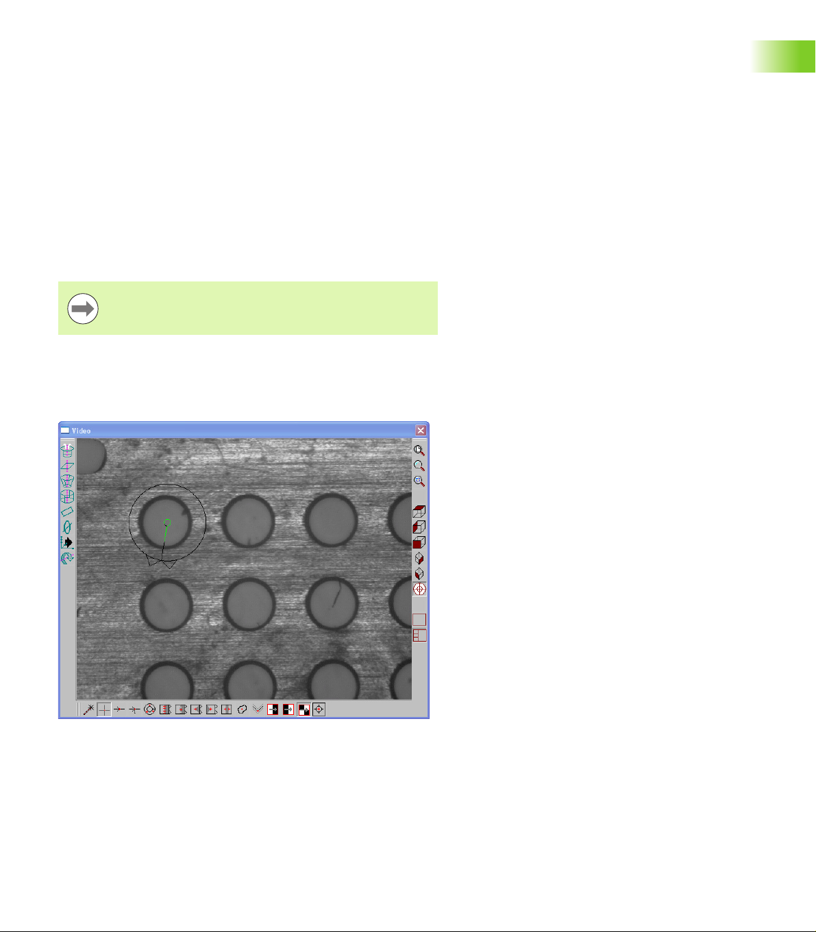
To create a grid:
Position the first array feature as shown
1.1 Operation
IK 5000 QUADRA-CHEK 15
Page 16
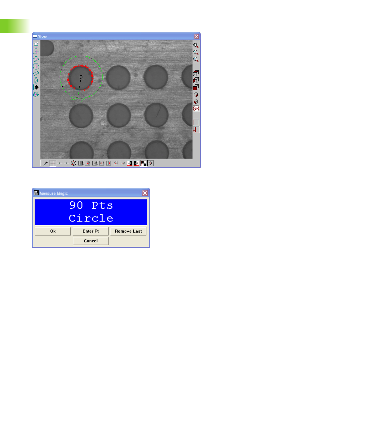
Click the center mouse button to fire the probe tool
1.1 Operation
Click OK in the dialog box
16 1 Operation
Page 17

Highlight the first array feature in the Program template as shown
Right-click in the Program template and select Programming Wizards,
then select Create a Grid
1.1 Operation
IK 5000 QUADRA-CHEK 17
Page 18
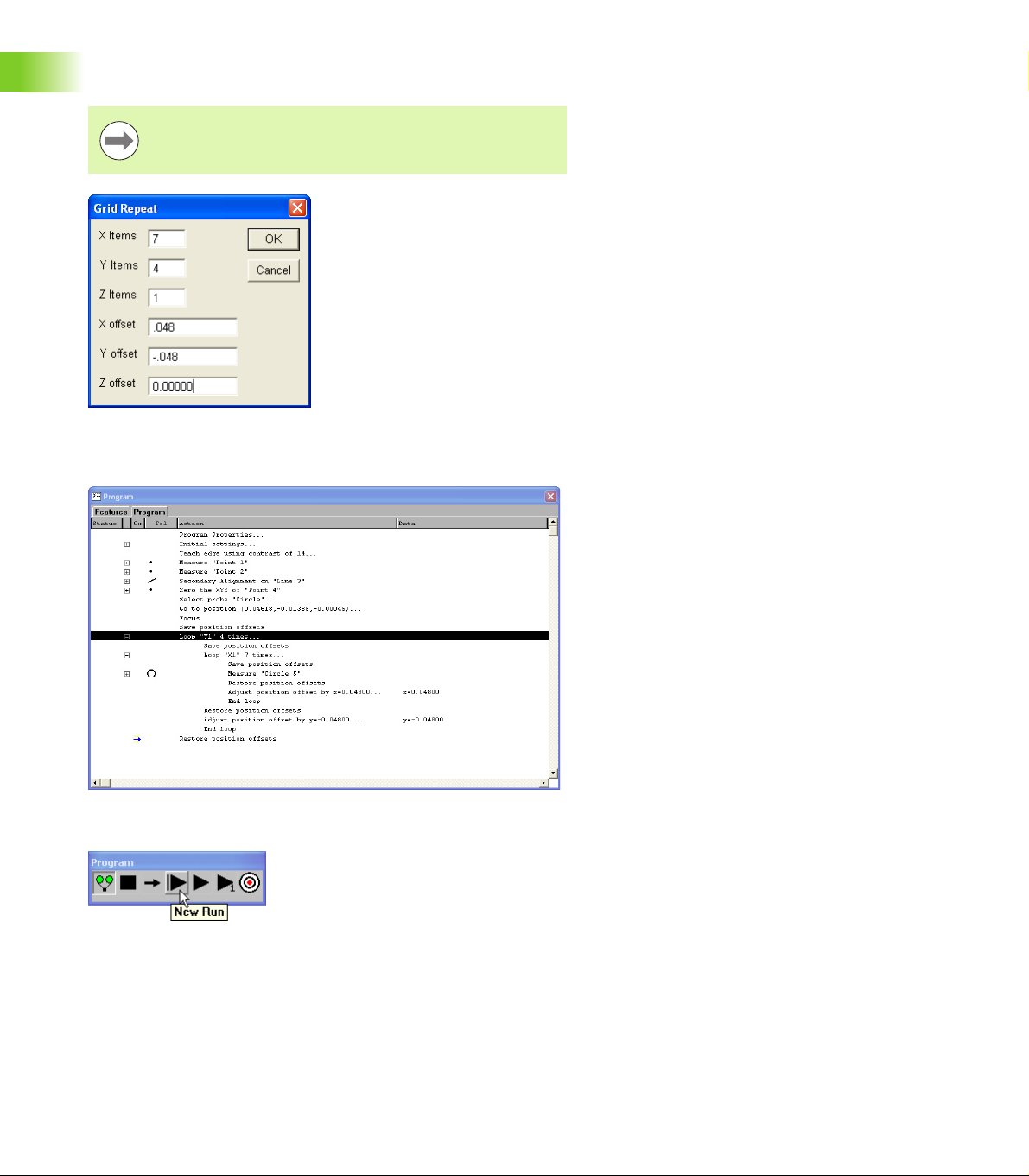
Enter the number of features and type in the desired X and Y offsets
as shown
Items are the number of features in each axis direction.
Offsets are the distance to the next feature relative from
previous feature.
1.1 Operation
Click OK in the dialog box
The grid is created and the program is ready to run
Click New Run to run the program
18 1 Operation
Page 19
Polar grids
A polar grid measures a part with like features that are in a rotational
array. For example, create a polar grid to measure a bolt hole pattern.
The programming wizard that creates a polar grid requires the user to
input the number of features and the angle between the features.
All features in a polar grid must be evenly spaced.
Before creating a polar grid, create a new part program. Use the center
of the polar grid features as the zero point of the part.
Make certain the program is recording before completing
the following steps.
To create a polar grid:
Position the first feature in the polar array in the center of the field
of view as shown
1.1 Operation
IK 5000 QUADRA-CHEK 19
Page 20

Select Measure>Circle
1.1 Operation
Click Enter Point in the Measure Circle dialog
Click OK
Select the measured Circle in the Program template
Select Tools>Programming>Programming Wizards>Create a Polar
Grid
Enter the number of times to loop in the Times to Repeat field
Enter the loop increment angle in the Angle Increment field
Click OK
The polar grid is created and the program is ready to run.
20 1 Operation
Page 21
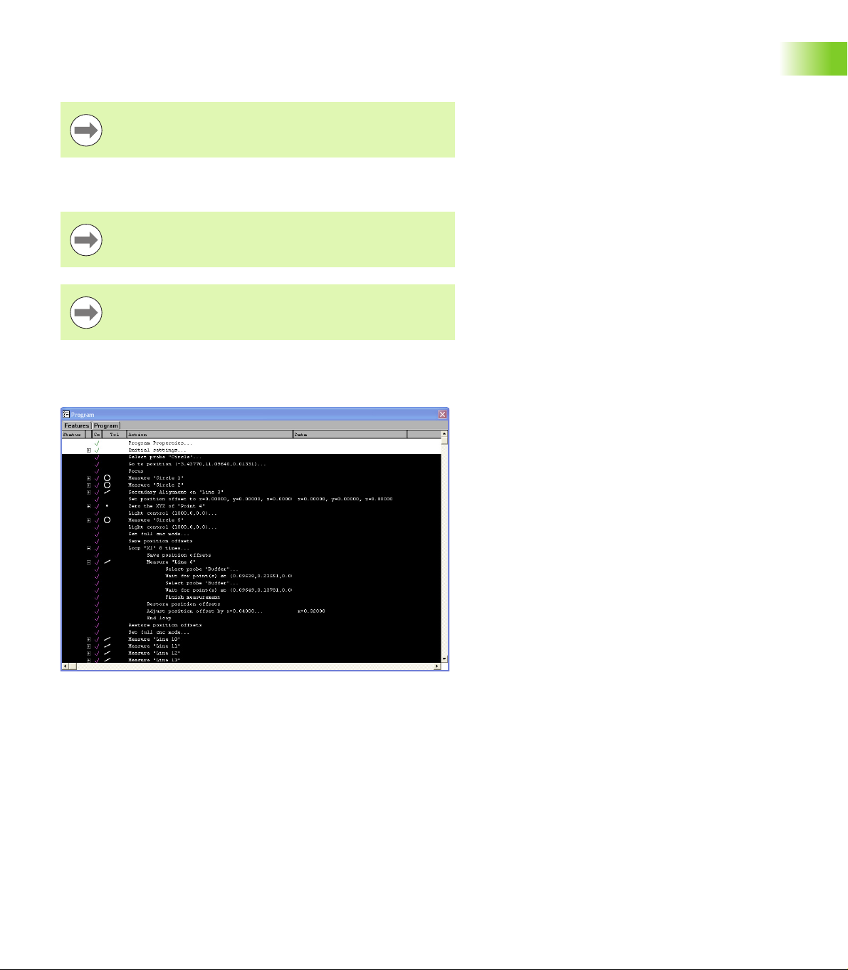
Palletize
Use the Palletize wizard for measuring multiple parts placed on a
precision fixture.
All palletized parts must be in a fixture that evenly spaces
the individual parts.
Before palletizing parts, create a new part program measuring all the
features of the part.
Save the reference frame in the part program immediately
after creating the datum.
Make certain the program is recording before completing
the following steps.
To palletize multiple parts:
Highlight the desired features as shown
1.1 Operation
IK 5000 QUADRA-CHEK 21
Page 22
Right-click in the Program template and select Programming Wizards,
then select Palletize
1.1 Operation
Enter the number of features and type in the desired X and Y offsets
as shown
Items are the number of parts in each axis direction.
Offsets are the distance to the next part relative from
previous part.
22 1 Operation
Page 23
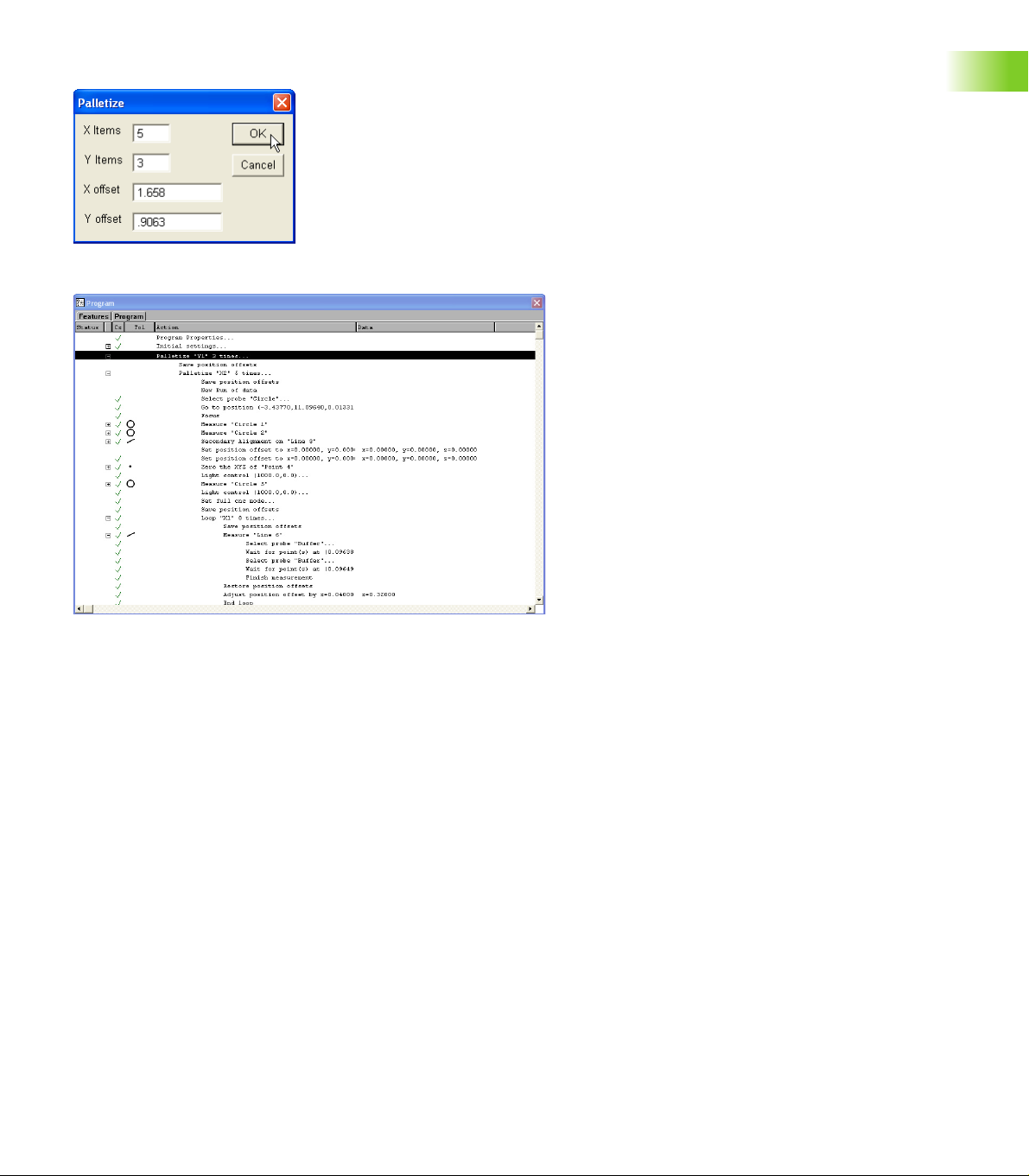
Click OK in the dialog box
The palletization is completed and the program is ready to run.
1.1 Operation
Click New Run to run the program
IK 5000 QUADRA-CHEK 23
Page 24
Random placement
Use the Random Placement wizard for multiple parts on a stage
without a fixture.
All parts must have the same orientation on the stage and
be square to the axes of the machine.
Before creating a random placement, create a new part program with
1.1 Operation
reference steps.
Reference steps
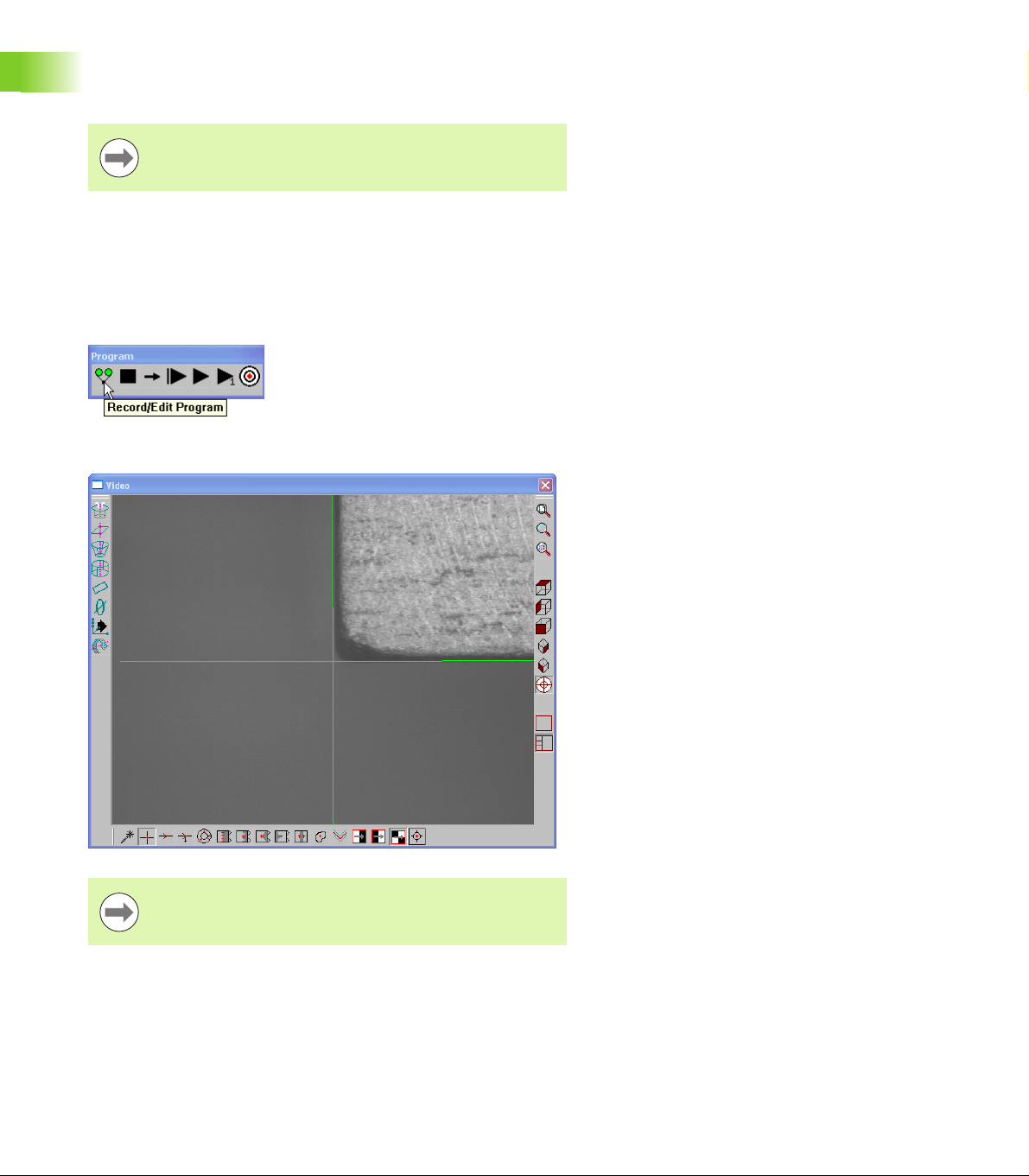
To insert reference steps in a part program:
Click the Record/Edit button on the Program toolbar
Position the desired reference feature as shown
The reference feature is a repeatable point to help the
IK 5000 locate the randomly placed parts.
24 1 Operation
Page 25
Click the center mouse button to fire the probe tool
Click OK in the dialog
1.1 Operation
The IK 5000 will use this feature to locate the randomly place parts.
Create a the rest of the part program measuring all the features of the
part.
Save the reference frame in the part program immediately
after creating the datum.
IK 5000 QUADRA-CHEK 25
Page 26
Random Placement
To create a random placement:
Make certain the program is recording before completing
the following steps.
Highlight the desired features, and the reference point as shown
1.1 Operation
Right-click in the Program template and select Programming Wizards,
then select Random Placement
26 1 Operation
Page 27
The IK 5000 inserts the required steps for the random placement.
To run a parts program with a random placement:
Click the New Run button on the Program toolbar
1.1 Operation
IK 5000 QUADRA-CHEK 27
Page 28
Measure the reference point for the first part
1.1 Operation
Repeat these steps until all parts are entered.
Click OK in the dialog box
Click the Remove Last button to remove the last point
enter. Reenter the point for that part.
Click the Use Last Run button to use the same offsets as
the previous run.
28 1 Operation
Page 29
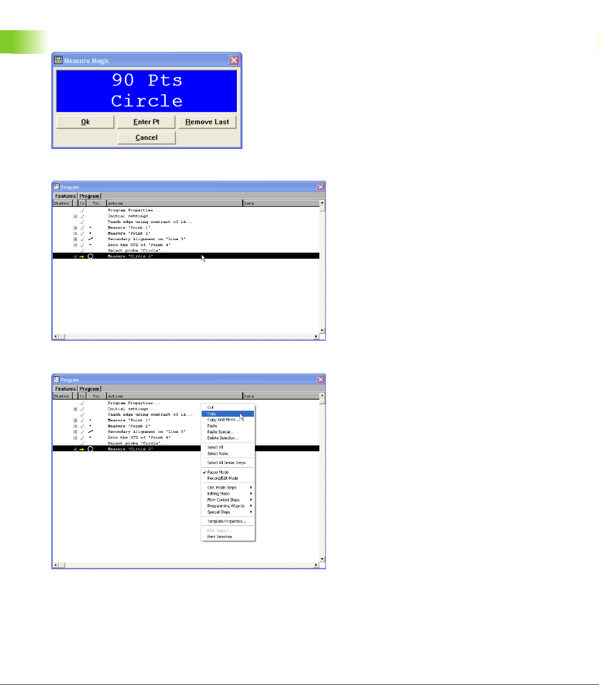
Copy and paste special
Before performing a copy and paste special, record a new part
program with a datum.
To copy and paste special:
Position the first array feature as shown
1.1 Operation
Click the center mouse button to fire the probe tool
IK 5000 QUADRA-CHEK 29
Page 30
Click OK in the dialog box
1.1 Operation
Highlight the first array feature in the Program template as shown
Right-click in the Program template and select Copy
30 1 Operation
Page 31

Right-click in the Program template and select Paste Special
Enter the number of Items and type the desired X and Y offsets as
shown
1.1 Operation
Items are the number of features in each axis direction.
Offsets are the distance to the next feature relative from
previous feature.
IK 5000 QUADRA-CHEK 31
Page 32

Click OK in the dialog box
1.1 Operation
The IK 5000 creates a grid on the part view and assigns a numbered
feature name to each feature in the grid.
32 1 Operation
Page 33

The copied and pasted parts appears in the Part View window as
shown.
The program is ready to run.
1.1 Operation
IK 5000 QUADRA-CHEK 33
Page 34

Additional tolerance check Axial Runout for Plane feature
Axial runout tolerance can be applied to a Plane feature that is
perpendicular to a reference axis, e.g. plane to cylinder.
To apply axial runout tolerance:
Measure a cylinder to be used as a reference in the tolerance
Measure the plane to apply the axial runout tolerance to
1.1 Operation
Select the Plane feature in the Features template
Select Tools>Tolerance>Axial Runout
Enter tolerance parameters
Click ok
Tolerance results are displayed.
Select
Tools>Tolerance>Axial Runout
34 1 Operation
Enter tolerance parameters and
click OK
Tolerance results are displayed
Page 35

Palletizing multiple parts
A pallet is a rectangular arrangement of identical parts organized into
a consistent matrix of columns and rows. The X and Y offsets between
parts in the matrix must be the same for all parts.
Once a part program is created and tested for a single part, it can be
run on each of the identical parts contained in a pallet. The IK 5000 will
begin measuring parts at the lower-left corner of the pallet, and will
proceed from left to right and from bottom to top.
To specify the fixturing mode:
Double click Program Properties in the Program template. The
Program Properties dialog is displayed.
Click the Palletize tab. The pallet setup parameters will be
displayed.
Enter the Number of Columns and Number of Rows into the fields
provided
Enter the X Offset and Y Offset between parts into the fields
provided
When it is known that some pallets will not be full, the program can
prompt the operator at the beginning of each run to specify the
location of parts contained by the current pallet. Check the Prompt
user for position of loaded pallet elements check box to
prompt the operator.
Click OK
1.1 Operation
Pallet of 12 identical parts
Enter pallet parameters
IK 5000 QUADRA-CHEK 35
Page 36

Profile import points
Probed points from features can be imported into a profile
measurement when recording a program. This eliminates the need to
re-probe points for contours that make up features already measured
in the same program.
All features whose points are used in the import process
need to exist during program playback or the import
1.1 Operation
To import points into a Profile measurement:
Start recording a program
Measure features into the program by probing them
function will fail.
Start a Profile measurement
Select the features whose data cloud will be imported into the
measurement as probed points
36 1 Operation
Page 37

Click Import Pts
Points are imported into the Profile measurement.
1.1 Operation
Click OK
IK 5000 QUADRA-CHEK 37
Page 38

Measuring rectangles
3
21
5
4
3
Precisely five probed points are required to measure a rectangle. The
five points must be located in an exact pattern, and can be probed in
either clockwise or counterclockwise order.
The correct pattern of points probed around the rectangle are:
Two points evenly distributed along one long side
One point on the closest end
1.1 Operation
One point on the approximate center of the second long side
The last point on the remaining end
Probing a different pattern of points, or probing out of
either clockwise or counterclockwise order will result in
erroneous rectangle measurements.
Measurement results are shown in the Features template, Part View
window and Results window. The Results window shows:
The feature identification number
The number of points used in the measurement
The length and width of the rectangle
The angular orientation of the rectangle
The coordinate location of the center of the rectangle
Only the rectangle shape and orientation are shown in the Feature
stamp of the Results window.
12
5
4
Clockwise probing order
Counterclockwise probing order
38 1 Operation
Page 39

Profile3D measurements
Profile3D measurements compare probed part surfaces to nominal
part profiles from drawing or part data files. Probed surfaces and
nominal profile surfaces are compared in the Measure Profile3D
window.
The nominal part profile can be imported into the Measure Profile3D
window from a drawing file in .IGS or .STP formats.
As surfaces are probed, their points are displayed in the Measure
Profile3D window. When the desired surface measurements are
complete, a fit operation is performed. During the fit operation, the
system positions the probed data over the nominal profile and adjusts
the X, Y, Z and rotational orientation of the probed points to achieve
the best fit. Data points are shown as dots and form errors are shown
as whiskers.
1.1 Operation
Probed points shown in Measure
Profile3D window
Tolerances can be applied to Profile3D measurements as bilateral
limits or as unilateral pass/fail boundaries. Bilateral tolerances can be
distributed equally or unequally on opposite sides of a surface.
The form errors, the number of data points and tolerance pass/fail
results can be displayed in the Measure Profile3D window at the
conclusion of the Fit operation. Upon completion of the Profile3D
measurement, the Profile3D feature is listed in the Features template.
The form error of each surface point is listed in the Points Detail
template and can be visually inspected using the Profile3D Feature
Stamp.
Points Detail template Profile3D feature stamp
Fit operation performed and form
error whiskers shown
IK 5000 QUADRA-CHEK 39
Page 40

Profile3D measurement screen functions
Functions for conducting Profile3D measurements are located across
the bottom of the Measure Profile3D window. These functions are
discussed in detail later in the Profile3D measurement instructions.
1.1 Operation
Measure Profile3D window
The Measure Profile3D window functions are shown below:
Functions Function descriptions
OK Complete the Profile3D measurement
Enter Pt Probe part surfaces
Remove Last Remove the last probed points
Cancel Cancel the Profile3D measurement
Fit Fit probed data to the nominal Profile3D
Reset Reset the fit operation
Export Export the adjusted Profile3D model
Tolerance Assign surface tolerances
Allow X, Y, Z Allow (or prohibit) data shifts during Profile3D fit analyses
Allow AX, AY, AZ Allow (or prohibit) data rotation during Profile3D fit analyses
Pass Only Enable (or disable) Pass Only option
40 1 Operation
Page 41

Profile3D window menu
Functions for evaluating and displaying Profile3D measurement
results are contained in the Measure Profile3D window menu.
Right-click anywhere in the Measure Profile3D window to display the
Measure Profile3D menu.
1.1 Operation
Measure Profile3D window menu
The Measure Profile3D window menu functions are shown below:
Functions Function descriptions
Zoom All Zoom to fit model in window
Zoom Window Click and drag to select an area to zoom in on
Zoom In Zoom in to show more detail
Zoom Out Zoom out to show less detail
Rotate Rotate the model around the datum
Pan Move the model in the measure window
Maximize Expand the measure window to the full size of the IK 5000 application window
Preset views Set the viewpoint of the model to a predefined view
Solidify Toggle between a wireframe and solid model
Transparency Adjust the percentage of transparency for surfaces of a solid model
Error Mag Magnify the display of form error whiskers
Alignment Adjust the model to match the orientation of the part to the shape
IK 5000 QUADRA-CHEK 41
Page 42

The Profile3D measurement process
1
2
3
8
4
5
6
7
A
B
C
Typical steps required to complete a Profile3D measurement are
shown below. Details regarding the use of measurement windows,
menus and toolbar tools are included in the instructions.
1.1 Operation
Profile3D measurement process
Profile3D measurement process steps are shown below:
Requirement Step System activity
A Measure 1 Start Profile3D measurement
A Measure 2 Import part profile
A Measure 3 Enable data shifts for fit
A Measure 4 Assign tolerances
A Measure 5 Probe part surfaces
A Measure 6 Perform Profile3D fit analysis. Go to step 5 and probe more points
B Review and adjust results 7 Adjust display magnification of error whiskers. Go to step 5 and
C Complete measurement 8 Add Profile3D feature to the Feature template
42 1 Operation
if needed.
probe more points if needed.
Page 43

Start Profile3D measurement
To begin a Profile3D measurement:
Click Measure>Profile3D
or
Click the Profile3D icon button on the Measure toolbar
Start a Profile3D measurement from the Measure toolbar
The Import Profile dialog will be displayed. A nominal part profile can
be imported from a drawing file. Drawing files can be in the .IGS or
.STP format.
Import part profile
Select the desired .IGS or .STP file and then Click Open
1.1 Operation
Start a Profile3D measurement from the Measure
menu
Select file
IK 5000 QUADRA-CHEK 43
Page 44

The nominal Profile3D will be shown in the Measure Profile3D
window.
1.1 Operation
Nominal Profile3D shown in Measure Profile3D window
44 1 Operation
Page 45

Enable or prohibit data shifts for Profile3D fit
The Profile3D fit algorithm shifts the probed data points in the
cartesian or polar coordinate system to achieve the best fit between
the probed points and the nominal part profile.
Maximum degrees of freedom are given to the fit algorithm by
checking the Allow X, Allow Y, Allow Z, Allow AX, Allow AY and
Allow AZ check boxes across the bottom of the window. Clearing a
check box prohibits data movement in the indicated orientation.
To give maximum degrees of freedom to the Profile3D fit algorithm:
Check the Allow X, Allow Y, Allow Z, Allow AX, Allow AY and
Allow AZ check boxes across the bottom of the Measure Profile3D
window
1.1 Operation
Check all check boxes for maximum degrees of freedom
Clear a check box to prohibit movement of data in the indicated
orientation
Allowing the maximum degrees of freedom for the
Profile3D fit algorithm is recommended for most
applications.
IK 5000 QUADRA-CHEK 45
Page 46

Assign tolerances
Bilateral or unilateral tolerances can be assigned to Profile3D
measurements. Bilateral tolerances can be equal or unequal.
To begin applying tolerances:
Click the Tolerance button to display the Profile Tolerance Edit
dialog
1.1 Operation
Begin applying tolerances
46 1 Operation
Page 47

Equal bilateral tolerances
Bilateral tolerance values will be centered on the surface of the
nominal profile. For example, an equal bilateral tolerance of 0.005 will
be applied as ±0.0025.
To apply an equal bilateral tolerance:
Check the Bilateral check box, enter the desired tolerance value
into the Tolerance field for equal bilateral tolerances and then click
OK
Apply equal bilateral tolerances
Unequal tolerances
Unequal or unilateral tolerance values are specified by the user for Inmaterial and Out-material tolerances.
To apply an unequal tolerance:
Uncheck the Bilateral check box, enter the desired
In material Tol and Out material Tol tolerance values in the
fields provided and then click OK
1.1 Operation
Apply unequal tolerances
IK 5000 QUADRA-CHEK 47
Page 48

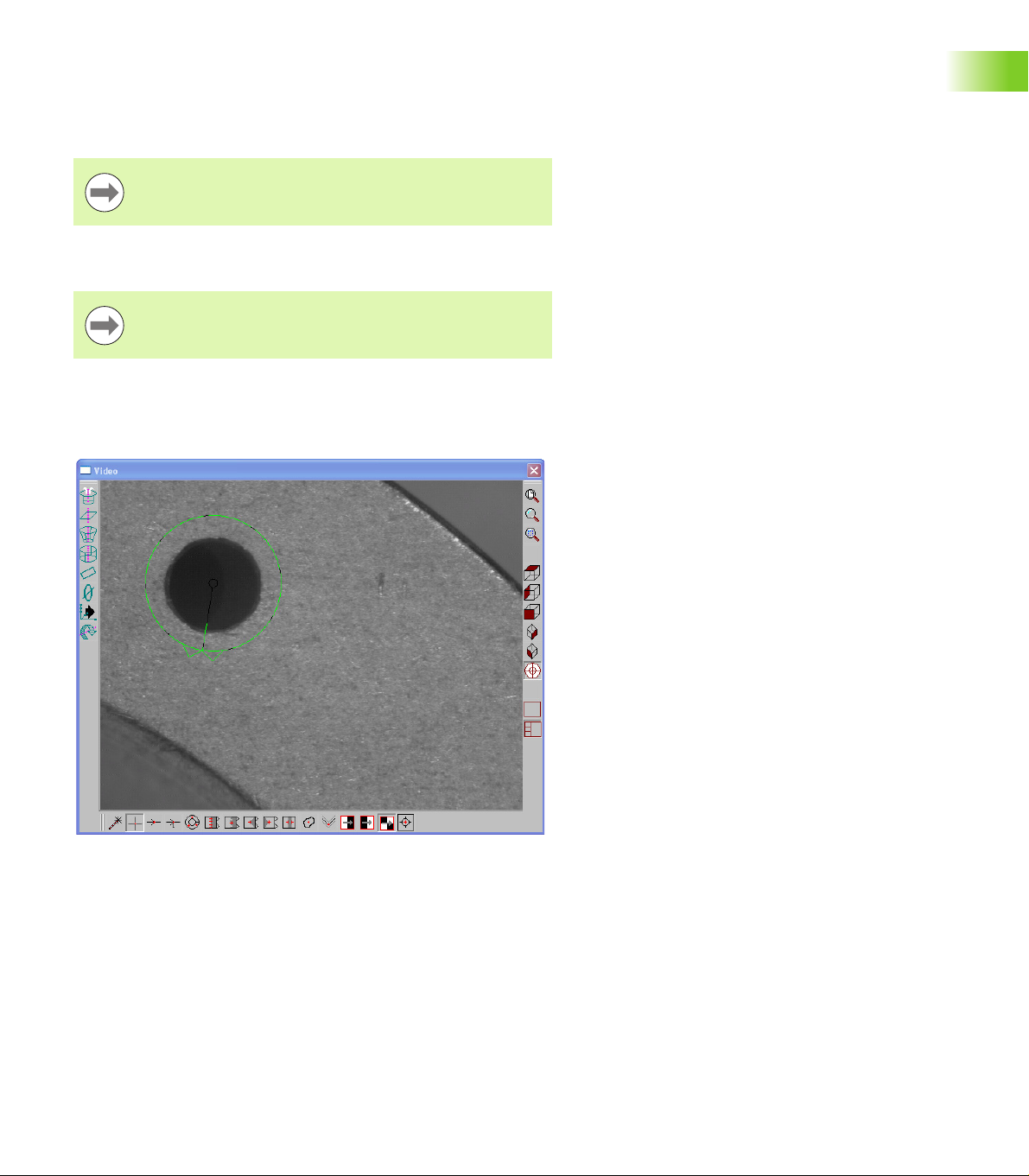
Probe part surfaces
As part surfaces are probed and points are collected, they appear in
green in the Measure Profile3D window.
When Auto Enter is enabled points will be entered
automatically as they are probed.
To enter a probed point manually:
1.1 Operation
Click Enter Pt in the Measure Profile3D window
Enter points from the Measure Profile3D window
To remove the last point(s) collected:
Click Remove Last
To cancel the Profile3D measurement:
Click Cancel
If a point was probed in a non-perpendicular direction to
the surface during program recording, the system will
probe that point orthogonal to the surface during program
playback as long as the fit analysis was done and
completed.
48 1 Operation
Page 49

Perform Profile3D fit analysis
When all the required points have been probed, the points can be fit
to the nominal part model.
When the fit operation is complete, the green probed points will be
shifted to match the part model as closely as possible and form error
whiskers will indicate differences between the probed locations and
the nominal part surfaces.
1.1 Operation
Points shown before fit calculation Form error whiskers shown after fit operation
To perform a fit analysis:
Click Fit
To decrease the fit analysis time, well distributed points all
around the part under measure are recommended. In
addition, part alignment and datum can be performed
before commencing the Profile3D measurement or using
the Six Point alignment function in the Profile3D
measurement.
IK 5000 QUADRA-CHEK 49
Page 50

Profile3D automatic fit analysis
The fit analysis can be set to be performed automatically once the
measurement is completed by clicking the OK button.
To select the Profile3D automatic fit analysis option:
Select Tools>Options...
Select the Measure tab
Select the Automatically fit Profile3D when measurement
complete checkbox
1.1 Operation
Select Tools>Options
Click OK
50 1 Operation
Page 51

Profile3D Pass Only option
The Pass Only option on the Profile3D Measure window specifies that
the fitting algorithm terminates the fitting process when it finds a fit
that is within all specified surface tolerances. If the Pass Only option
is checked, and a tolerance has been specified for every surface on
which points have been probed, then the fitting algorithm will
terminate as soon as it finds a fit in which all probed points pass their
tolerance. If no such fit can be found then the fitting algorithm will
continue the process of fitting until it either finds the best fit it can or
none is found.
The Pass Only option is used to improve performance in cases where
time is a more important factor than accuracy. This is to be used when
a tolerance pass/fail is all that is required and not the exact amount of
the error. The amount of performance improvement varies depending
on how loose the tolerance is, and how close the part is to its nominal
form. The fitting of a part that fails its tolerance will not have any
performance improvement by using the Pass Only option.
To select the Pass Only option:
Select Measure>Profile3D
Select the Pass Only checkbox
Click OK
1.1 Operation
Select the Pass Only checkbox
IK 5000 QUADRA-CHEK 51
Page 52

Six point alignment
A six point alignment allows the operator to align the model with the
orientation of the part on the stage.
To perform a six point alignment:
Right click in the Measure Profile3D window
Select Alignment>Six Point. A prompt appears with directions for
marking points on the model.
Select OK in the prompt
1.1 Operation
Mark three points on the model surface to define a primary plane
Mark two points on the model on a surface that is close to
perpendicular to the first surface to define a secondary line
Mark one point on the model on a surface that is close to
perpendicular to both the first and second surfaces to define a zero
point
When six points are selected the first point is highlighted on the model
Six points selected and first point highlighted
Probe the first point on the part. The next point is highlighted on the
model.
Repeat probing the remaining five points
Select Fit in the Measure Profile3D window. The six point
alignment is completed and the initial fit is done.
52 1 Operation
Page 53

Resetting the fit analysis
The results of a fit analysis can be reset and the point data refined in
preparation for revised fit operations. The user can review the
positions of data points, remove data points or change the degrees of
freedom for the fit analysis.
To reset the fit analysis back to the original probed point locations:
Click Reset
1.1 Operation
Points shown after resetting the fit analysis
IK 5000 QUADRA-CHEK 53
Page 54

Adjust the display magnification of error whiskers
During the fit analysis, probed points that do not fall precisely on the
nominal profile generate form errors. When tolerances are specified,
the errors are divided into two groups, those that pass (Passed) and
those that fail (Failed) tolerance criteria.
The passed and failed form errors can be displayed as whiskers that
extend from the nominal surface. The length of each whisker is
proportional to its magnitude of error.
Typically, the magnitude of most form errors is so small in proportion
1.1 Operation
to the part displayed that without magnification they would not be
visible. The Measure Profile3D window menu and toolbar include
fixed, automatic and user-definable levels of magnification for
displaying error whiskers.
Fixed magnifications: display magnifications are selected directly by
the user.
Automatic magnification (AX): the system optimizes the display of
error whiskers based on the maximum form error value.
User-defined magnification (UX): A data field will be displayed for
specifying the level of magnification.
To adjust the display magnification of form error whiskers:
Right-click the Measure Profile3D window to display the Measure
Profile3D window menu
Click Error Mag to display a menu of magnification alternatives
Click the desired magnification selection
Select error magnification from Measure Profile3D
window menu
54 1 Operation
Page 55

Add Profile3D feature to the Feature template
When the final fit analysis is finished, the Profile3D measurement can
be completed and the Profile3D feature can be added to the Feature
template.
To complete the Profile3D measurement:
Click OK in the Measure Profile3D window
1.1 Operation
Complete the Profile3D measurement
IK 5000 QUADRA-CHEK 55
Page 56

To view the Profile3D measurement results:
Click on the Feature Stamp Icon in the results window
1.1 Operation
Profile3D feature stamp
Measurements results are also available in the PointDetails
template.
PointDetails template
If the PointDetails template is not open it can be viewed
by clicking Windows>Open Template... and selecting
PointDetails.5ft.
56 1 Operation
Page 57

Auto Focus (option)
The Auto Focus teach function has been removed from the IK 5000
software. The focus search distance is now entered directly into the
search distance field. The previous Auto Focus algorithm used the
teach function to teach the optimum search distance and Z axis
velocity, depending on the connected camera's frame rate. This could
cause an intermittent Auto Focus failure when used on a significantly
different surface from the surface used during the teach process. The
algorithm now automatically adjusts the Z axis velocity depending on
the camera frame rate and the user specified search distance.
High resolution cameras may produce less than optimal results which
can be improved by decreasing the search distance. Decreasing
search distance also speeds up the focal point acquisition time but
requires initial position to be closer to the targeted focal point. On
some cameras turning on the despeckle filter prior to performing auto
focus will improve results, despeckle filter can then be turned off after
focus.
To turn on the despeckle filter:
Right click on the Video window and select Filter...
Check the Despeckle checkbox
Click OK
1.1 Operation
Right click the Video
window and select Filter...
IK 5000 QUADRA-CHEK 57
Check the Despeckle box and click OK
Page 58

To set Auto Focus options:
Click Tools>Options
Verify the Supervisor Password is entered and the Keep privileges
until program is exited option is checked
Click Probe>Probe Library
Click on the target camera
1.1 Operation
Verify the Password is entered and Keep
Click Probe>Probe Library Click on the target camera
privileges until program is exited is
checked
Click on the target magnification
Click the Auto Focus tab
Enter the desired search distance in the Search Distance field
Click OK to save the changes and exit the Probe Library
Click on the target magnification Click the Auto Focus tab Enter the desired search distance and
click OK
58 1 Operation
Page 59

Auto focus will search and make as many passes as necessary until a
optimum focus point is found. The Max two passes feature limits the
number of auto focus passes to two. Selecting this feature can speed
up the auto focus process but may result in less reliable repeatability
of the auto focus height.
To enable Max two passes:
Select the Max two passes check box
Select the Max two passes check box
1.1 Operation
IK 5000 QUADRA-CHEK 59
Page 60

Autofocus final check
An option to perform a final autofocus check is available from the
Auto Focus tab in the Probe Library.
Enabling a final check helps to avoid missing an optimum focus point
when autofocusing with a search distance smaller than 1 mm and a
magnification greater than 20 x. An optimum focus point can be
missed due to skipping of the focus frames during the focus search,
machine drive mechanics, changes in lighting, or the objective lens
1.1 Operation
being used.
A final check compares the difference in contrast values of frames in
the range of 5 µm above to 5 µm below the initial focus point. If there
is a point with a larger contrast value found the system will focus on
the point of greater contrast.
To enable the the autofocus final check:
Select Probe>Probe Library...
Select the target camera and target magnification
Select the Autofocus tab
Check the check box next to Enable final check
Click Probe>Probe Library... Check the check box next to Enable final check
60 1 Operation
Page 61

Exploding the Data Cloud
Explode Data Cloud is used to extract point features from the data
cloud used in a probed feature.
To extract point features from the data cloud:
Verify the system is in No Program or Editing state of programming
Probe a feature
Select the target feature
1.1 Operation
Verify the system is in
No Program or Editing
state
Click Tools>Explode Data Cloud.
The Features List is populated with point features created from the
data cloud of the selected feature.
Probe a feature Select the target feature
Click Tools>Explode Data Cloud Point features are created from the data cloud
IK 5000 QUADRA-CHEK 61
Page 62

Rotating and positioning of VED tools using part reference frame
If a part datum has been performed, the system will rotate and
position the VED tools, including the Video Charts, to the part
reference frame.
ISO Tolerance
1.1 Operation
The ISO tolerance enables the use of data stored in ISO 286-2
Standard tables.
The ISO tolerance can be added to the following features:
Point
Circle
Arc
Sphere
Line
Slot
Torus
Rectangle
The ISO tolerance is applied to a feature similar to other tolerances, for
instance by right-clicking on a feature in the Features list template.
Right-click on a feature in the Feature list
62 1 Operation
Page 63

Once the ISO tolerance is selected the ISO Tolerance Entry dialog
box appears. The ISO Tolerance Entry dialog box is used to select
which ISO tolerance table entry will be used to tolerance each
applicable feature parameter.
ISO tolerance entry table
Available parameter selections are:
ISO table
ISO Index
The ISO index entry can be used to select which column, 1 through
18, to use for the selected ISO tolerance table. For questions about
the ISO tolerance table selection please refer to the ISO 286-2
standard.
1.1 Operation
IK 5000 QUADRA-CHEK 63
Page 64

The nominal value for the feature parameter along with the selected
ISO tolerance table and index entries are used to determine the low
and high limits to be used when tolerancing the feature. These limits
are calculated through a look-up into the ISO tolerance table. If no ISO
tolerance table entry or ISO tolerance index entry is specified then the
tolerance is considered empty and the tolerance will pass. Also, if the
nominal value for the feature parameter is outside of the range of
nominal values found within the selected tolerance table, then the
tolerance will also pass.
1.1 Operation
ISO tolerance results
Similar to all tolerances, the ISO tolerance can be added to features
within a program.
ISO tolerance added to a feature in a program
The ISO tolerance results can also be viewed in reports when using
the AllTol template.
64 1 Operation
Page 65

AllTol template
1.1 Operation
IK 5000 QUADRA-CHEK 65
Page 66

Continuous probe firing
Probes can be dry-fired continuously to show data points that would
be acquired under the current light, focus, part alignment and other
current measurement conditions if the probe were actually fired. The
data points are shown in blue until the probe is fired to acquire points,
then the acquired points are shown momentarily in red.
1.1 Operation
Continuous Fire enabled
Continuous probe firing is useful for setup and
troubleshooting activities, but requires substantial system
resources and should be avoided during routine use to
maintain high throughput.
To enable Continuous Fire:
Right-click the Live Video window to display the Window menu
Select Other>Continuous Fire
or
Click the Continuous Fire button on the VED toolbar
Enable Continuous Fire from VED toolbar
Enable Continuous Fire from menu
66 1 Operation
Page 67

Programming continuous probe firing
Continuous probe firing is programmable. A Continuous Fire mode
step is recorded in the Initial settings program step when a new
program is recorded. Continuous probe firing is turned off in the Initial
settings step by default.
After a program is run the state of Continuous Fire returns
to the same state that was in place before the program
was executed.
Initial settings step
Enable Continuous Fire from Initial settings... step
1.1 Operation
To turn Continuous Fire on in the Initial settings:
Click the + sign next to Initial settings... to expand the Initial
settings step in the program window
Double-click Turn off continuous fire mode...
The text changes to Turn on continuous fire mode.... Continuous
Fire mode will now be turned on when the program is run.
IK 5000 QUADRA-CHEK 67
Page 68

Program step
When the state of Continuous Fire is changed from the Live Video
window or the VED toolbar, a separate Continuous Fire step is
recorded in the program. The state of this step can be changed.
1.1 Operation
Change the state of a Continuous Fire program step
To turn Continuous Fire off in an existing program step:
Double-click on Turn on continuous fire mode...
Turn off continuous fire mode... is displayed in the Program
window and the program will now turn Continuous Fire off at this step
in the program.
To turn Continuous Fire on in an existing program step:
Double-click on a Turn off continuous fire mode... step
Turn on continuous fire mode... is displayed in the Program window
and the program will now turn Continuous Fire on at this step in the
program.
68 1 Operation
Page 69

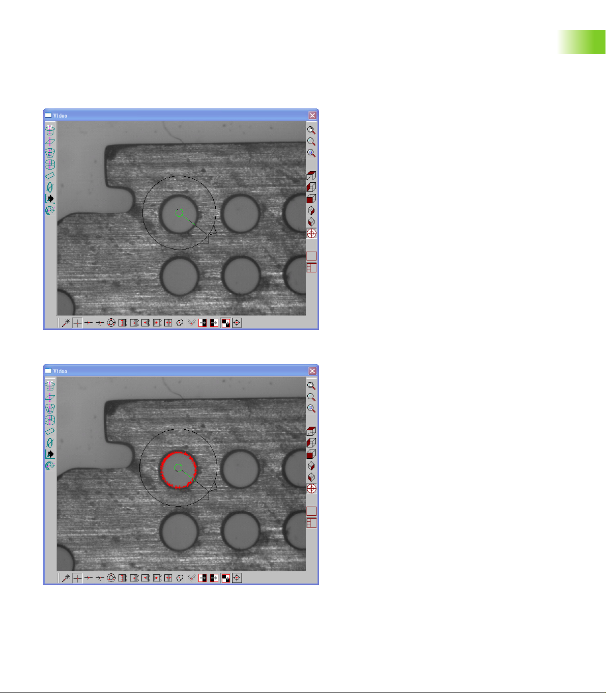
Measure shortcuts
Keyboard shortcuts for starting Ellipse, Torus, Profile, and Profile3D
measurements are now available. The shortcuts are listed in the
Measure menu.
In addition to the new measure shortcuts, the Rectangle menu item
has been moved to a more appropriate location in the Measure menu.
Ellipse shortcut
To start an Ellipse measurement:
Press Ctrl+E on the keyboard
Torus shortcut
To start a Torus measurement:
Press Ctrl+T on the keyboard
Profile shortcut
To start a Profile measurement:
Press Ctrl+F2 on the keyboard
Profile3D shortcut
To start a Profile3D measurement:
Press Ctrl+F12 on the keyboard
1.1 Operation
Measure menu
IK 5000 QUADRA-CHEK 69
Page 70

Symmetry tolerance
/LQH
5HIHUHQFHOLQH
/LQH
A symmetry tolerance can be applied to Line and Plane features that
are symmetrical to a reference feature.
Symmetry tolerance applied to a line
/LQH
1.1 Operation
To apply the symmetry tolerance to a line:
Measure four lines, two lines on opposite sides that are considered
to be master edges and two lines from edges that are to be
symmetrically toleranced. Lines 1 and 2 are measured from master
edges while lines 3 and 4 are measured from the edges to be
symmetrically toleranced.
Construct a reference line from lines 1 and 2
Construct the line to be tolerance for symmetry from lines 3 and 4
Select the resultant line from the construction using lines 3 and 4
7ROHUDQFHGOLQH
/LQH
70 1 Operation
Page 71

Apply symmetry tolerance with the constructed line from lines 1 and
2 as the reference feature
1.1 Operation
The actual tolerance is calculated by doubling the
maximum distance between the endpoints of the
constructed tolerance line from the endpoints of the
constructed reference line.
IK 5000 QUADRA-CHEK 71
Page 72

Symmetry tolerance applied to a plane
3ODQH
5HIHUHQFHSODQH
3ODQH
3ODQH
7ROHUDQFHGSODQH
1.1 Operation
3ODQH
To apply the symmetry tolerance to a plane:
Measure four planes, two planes on opposite sides that are
considered to be master surfaces and two planes from surfaces that
are to be symmetrically toleranced (see drawing above). Planes 1
and 2 are measured from master surfaces while planes 3 and 4 are
measured from the surfaces to be symmetrically toleranced.
Construct a reference plane from planes 1 and 2
Construct the plane to be toleranced for symmetry from
planes 3 and 4
Select the resultant plane from the construction using
planes 3 and 4
72 1 Operation
Page 73

Apply symmetry tolerance with the constructed plane from planes
1 and 2 as the reference feature
1.1 Operation
The actual tolerance is calculated by doubling the
maximum distance between the endpoints of the
constructed tolerance plane from the endpoints of the
constructed reference plane.
IK 5000 QUADRA-CHEK 73
Page 74

Plane probing technique
6HHGSRLQW
6HHGSRLQW
6HHGSRLQW
3UREHGSODQH
$FWXDOSODQHVXUIDFH
6HHGSRLQW
3UREHGSODQH
A plane can be measured by probing three seed points for the data
cloud. The IK 5000 fitting algorithm uses these three points as the first
three corners of the plane.
1.1 Operation
It is important to probe the three seed points on the corner surfaces
of the actual plane if the Add Probe Points function is used to add
more points to the data cloud of the plane measurement.
6HHGSRLQW
6HHGSRLQW
$FWXDOSODQHVXUIDFH
$GGHGSUREHSRLQWV
Correct probing technique
74 1 Operation
Page 75

In some cases it may be necessary to probe the seed points in a
6HHGSRLQW
6HHGSRLQW
6HHGSRLQW
3UREHGSODQH
$FWXDOSODQHVXUIDFH
5HDFKDEOH
SUREHG
6HHGSRLQW
3UREHGSODQH
different order and location. For example, probing the seed points
where the first two are located at the immediate corners facing the
operator while the third point is probed on the middle point of the
opposite edge.
The resulting plane cannot be used with the Add Probe Points
function because it will fail due to some points being located outside
the actual surface. The system will miss target points as they will be
located outside the actual plane and cannot be reached.
6HHGSRLQW
6HHGSRLQW
1.1 Operation
8QUHDFKDEOH
SUREHG
SRLQWV
Incorrect probing technique
$FWXDOSODQHVXUIDFH
SRLQWV
IK 5000 QUADRA-CHEK 75
Page 76

1.1 Operation
76 1 Operation
Page 77

Setup
Page 78

2.1 Setup
Updating the IK 5000 software
The update should be performed according to the following
procedure:
2.1 Setup
Make a backup of the IK 5000 system settings
Uninstall the installed IK 5000 software
Install the new IK 5000 software version
Restore the IK 5000 system settings
Backup system settings
Make a backup of the IK 5000 system settings (via
menu: Help>Backup Settings...)
Uninstall old software version
Uninstall the installed IK 5000 software with the tools provided by
the operating system (control panel)
Install new software version
Install the new software version 3.0.x
Restore system settings
Restore the IK 5000 system settings (via
menu: Help>Restore Settings...)
If an option that requires a license key is enabled the current license
key remains valid. A new license key is not required.
78 2 Setup
Page 79

Files and folders
IK 5000 files and folders locations are distributed throughout Windows
operating system folder locations in accordance with the operating
system's files and folders location guidelines.
The files and folders are distributed as follows:
IK 5000 files are located in the HEIDENHAIN\IK 5000 folder which is
in the Program Files OS folder
IK 5000 application is located in HEIDENHAIN folder in the Start
menu
Configuration files are stored in IK 5000 folder in Program Data OS
folder
User settings files are saved to the IK 5000 folder in Local User OS
folder
User document files are saved to the IK 5000 folder in the Documents
OS folder
Some file types that were supported in previous versions
are no longer used. File type .met is no longer supported.
Files of this type have been removed from the system.
2.1 Setup
IK 5000 QUADRA-CHEK 79
Page 80

PC2-COMP Express frame grabber board
The IK 5000 supports the PC2-COMP Express, PCI Express frame
grabber board produced by TeledyneDalsa Inc. This frame grabber can
be used in place of the previous Bandit II frame grabber board. The
PC2-COMP Express can be installed in systems running Windows XP,
Vista and 7.
2.1 Setup
The PC2-COMP Express frame grabber board is
compatible with 32-bit operating systems only.
This board must be obtained from HEIDENHAIN
This board must be installed on a computer with PCI Express slot
Bandit II and PC2-Comp Express cannot be installed at the same
time
PC2-COMP Express board
80 2 Setup
Page 81

Use current reference frame
Program Properties window
The Use machine reference option in the Program Properties dialog
has been renamed to Use current reference frame. When an
existing program is loaded into IK 5000 SW v3.0.0 or higher, the
Use current reference frame option will take on the opposite state
of the Use machine reference option.
The reference frame that is in place when a program is first recorded
is now stored within the program. If Use current reference frame is
unchecked, the program will use this stored reference frame as its
initial reference frame when the program is executed.
If Use current reference frame is checked, the program will use the
current part reference frame when the program is executed.
To change the current part reference frame:
Select a different part reference frame from the status bar
2.1 Setup
IK 5000 QUADRA-CHEK 81
Page 82

The default state of Use current reference frame is unchecked. If a
part reference frame has been created before the program is first
recorded Use current reference frame will be automatically
checked.
Programs written prior to SW v2.96.0 do not include the reference
frame that was in place when the program was first recorded. If
2.1 Setup
Use current reference frame is unchecked the program will use the
machine reference frame as the initial reference frame when the
program is executed.
If Use machine reference was previously used the same behavior can
be obtained with Use current reference frame.
To obtain the same behavior:
Select the machine reference frame prior to recording the program
Uncheck Use current reference frame in the Program Properties
dialog prior to executing the program
or
Check Use current reference frame
Select the machine reference frame prior to executing the program
82 2 Setup
Page 83

Camera parameters
The IK 5000 supports the configuration of camera and image quality
parameters through DirectShow interfaces. The configurable
parameters are limited to those provided by the camera driver support
for DirectShow. The IK 5000 cannot modify a parameter that the
camera driver does not allow to be modified.
Example configurable parameters are gamma, brightness, contrast
and color saturation. Brightness and contrast settings are saved when
the IK 5000 is shut down and restored on the next start up.
To access digital camera parameters:
Right-click in the Video window
Select Video Properties
A video properties window will open displaying the available camera
parameters that can be edited.
2.1 Setup
Right click in the Video window and select Video
Properties
Example video properties window
IK 5000 QUADRA-CHEK 83
Page 84

Specify video probe parameters
Use the VED screen in video edge detection systems to specify video
probe measurements parameters.
To display the VED screen:
Click Tools>Options...>VED
2.1 Setup
Digital video probe and measurement parameters will be displayed for
your system.
New options:
Camera: Select the camera to use for VED (previously unnamed)
Image format: Select the image color format
VED screen example
84 2 Setup
Page 85

Spotter camera options
The digital camera selected as the spotter camera and the format for
the spotter camera can be set from the VED setup tab.
2.1 Setup
Spotter camera options
IK 5000 QUADRA-CHEK 85
Page 86

Supported image formats:
UYVY
RGB24
RGB32
To access Spotter camera options:
2.1 Setup
Select Tools>Options...
Select the VED tab
Select a digital camera from the Spotter drop down menu
Select an image format from the Image Format drop down menu
Click OK
86 2 Setup
Page 87

Scale factor for Open Loop joystick control (Optional)
A CNC system can be operated in either Closed Loop or Open Loop
joystick control mode. This can cause a system to move with different
velocities when a user switches from one mode to the other. To make
the velocity comparable, a user can apply a scaling factor to the
joystick parameters when in open loop control mode. The Scale factor
ranges from 0.01 to 1.00. This is a unit-less value. The default value is
0.5.
Verify the system is set to Open Loop joystick control mode:
Click Tools>CNC...
Enter the Password
Click the General tab
Select the Set joystick control to Open Loop mode checkbox if
not already selected
2.1 Setup
Set joystick control to Open Loop mode
Click OK
IK 5000 QUADRA-CHEK 87
Page 88

Set Scale factor:
Click TOOLS>CNC...
Enter the Password
Click the Joystick tab
Enter the desired scaling factor into the Scale factor field
2.1 Setup
Enter the desired scaling factor
Click Apply
Click OK
88 2 Setup
Page 89

Shutdown
The Shutdown function applies to CNC enabled systems only. During
system shutdown the probe returns to a position defined in machine
coordinates regardless of probe type. The position may be specified
using X, Y and Z coordinates or by choosing the current probe location.
Shutdown settings window
To specify the probe position at shutdown:
Select Tools>CNC...
Enter the Supervisor password into the Password field
Select the Shutdown tab
Select the Enabled checkbox
Enter the X, Y and Z coordinates or click Use Current Location
Click OK
2.1 Setup
IK 5000 QUADRA-CHEK 89
Page 90

Debounce parameters
Y and Z axis debounce count values for the digital positioner use their
own axis value. Previously they used the X axis value.
2.1 Setup
Digital Positioner settings window
To specify debounce count values:
Select Tools>CNC...
Enter the Supervisor password into the Password field
Select the Digital Positioner tab
Enter values into the Debounce (cnts) fields
Click OK
90 2 Setup
Page 91

Touch probe requalification and starting point
Touch probe auto requalification can be set to Use circular moves and
to begin the requalification measurements at the top of the sphere and
not along the diameter.
Deselecting this option allows the automatic
requalification to be executed by linear movements,
minimizing stage vibrations for systems with large
measuring stages.
Auto Requal settings window
2.1 Setup
To select 'Auto Requal' parameters:
Select Tools>CNC...
Enter the Supervisor password into the Password field
Select the Auto Requal tab
Select the Begin measurement at top of sphere and Use circular
moves checkboxes
Click OK
IK 5000 QUADRA-CHEK 91
Page 92

Reset template text colors
It is possible to set the text color of a template to the same color as
the background. When this happens the text is not readable.
The Reset Template Text Colors option makes it simple to revert the
text colors for all open templates back to the default color. The default
2.1 Setup
text color for all templates is black.
To reset template text colors:
Select Help>Diagnostics>Reset Template Text Colors. A prompt
appears requesting verification to reset the text colors.
Select Help>Diagnostics>Reset Template Text Colors
Click Yes
Click Yes
92 2 Setup
Page 93

Default fixtures files location
A default location for Fixtures files can be selected. The IK 5000 uses
this location to save and load reference frames.
The default location is the Fixtures subfolder of the IK 5000 folder
located in the user's system documents folder.
To change the Fixtures file location:
Select Tools>Options...
Select the Files tab
Browse or enter a new Fixtures file location
2.1 Setup
Browse or enter a new Fixtures file location
IK 5000 QUADRA-CHEK 93
Page 94

External amplifier Open Loop control (Optional)
IK 5000 Open Loop joystick control provides the ability to toggle
between two joystick speeds when Speed Toggle is assigned to a
joystick button. External amplifier Open Loop joystick control provides
the ability to toggle between three speeds. The ability to toggle
between three speeds provides increased control over the velocity of
2.1 Setup
movements.
When Set joystick to Open Loop mode and Use external amplifier
for Open Loop control are enabled, Open Loop functionality is
controlled by the HEIDENHAIN amplifier connected to the IK 5000
system. Use external amplifier for Open Loop control is disabled
by default.
CNC window General settings tab
To enable external amplifier Open Loop control:
Select Tools>CNC...
Select the General tab
Select the Set joystick to Open Loop mode and Use external
amplifier for Open Loop control checkboxes
Click OK
94 2 Setup
Page 95

Joystick button assignment
Speed Toggle must be assigned to a joystick button in order use
joystick speed control. The HEIDENHAIN QUADRA-STEP setup
software is used to assign joystick button functions in the
HEIDENHAIN amplifier. QUADRA-STEP setup software and the
QUADRA-STEP setup guide can be downloaded from
www.heidenhain.de.
The IK 5000 and external amplifier both sense joystick button presses.
When Speed Toggle is assigned to a joystick button in the external
amplifier, the same button must be set to No Assignment in the
IK 5000 Options settings.
Options window Buttons tab
To set a IK 5000 joystick button assignment:
Click Tools>Options
Select the Buttons tab
Click the drop-down arrow for the joystick button Speed Toggle was
assigned to in the external amplifier
Select No Assignment
Click OK
2.1 Setup
IK 5000 QUADRA-CHEK 95
Page 96

2.1 Setup
96 2 Setup
Page 97

A
Auto focus ....................................... 57
Auto probe
Disc ............................................ 13
Grid ............................................ 12
Plane .......................................... 12
Autofocus final check ...................... 60
Axial runout ..................................... 34
C
Camera parameters ......................... 83
Continuous probe firing ................... 66
Copy and paste special .................... 29
D
Debounce parameters ..................... 90
Disc pattern auto probe ................... 13
E
Error whiskers display magnification ....
54
Explode data cloud .......................... 61
P
Palletize ........................................... 21
Palletizing multiple parts .................. 35
Part scaling ...................................... 10
PC2-COMP express frame grabber
board ............................................. 80
Plane auto probe .............................. 12
Plane probing ................................... 74
Polar grids ........................................ 19
Profile import points ........................ 36
Profile3D
Automatic fit analysis ................. 50
Data shifts .................................. 45
Fit analysis ................................. 49
Fit analysis reset ........................ 53
Measurement process ............... 42
Measurement screen functions 40,
41
Measurements ........................... 39
Pass only setting ........................ 51
Programming changes ..................... 14
Programming wizards ...................... 15
Index
F
Files and folders locations ............... 79
Fixtures files location ....................... 93
G
Grid pattern auto probe ................... 12
Grids ................................................ 15
I
ISO tolerance ................................... 62
K
Keyboard shortcuts
Ellipse ........................................ 69
Measure ..................................... 69
Profile ......................................... 69
Profile3D .................................... 69
Torus .......................................... 69
M
Measure
Rectangle ................................... 38
O
Open Loop control
External amplifier ....................... 94
Joystick button assignment ....... 95
Joystick control .......................... 87
R
Random placement ................... 24, 26
Reference steps .............................. 24
Reset template text colors .............. 92
S
Scale factor ...................................... 87
Shutdown ........................................ 89
Six point alignment .......................... 52
Spotter camera options ................... 85
Symmetry tolerance ........................ 70
System requirements ........................ 3
T
Touch probe
Requalification and starting point ....
91
U
Updating software ........................... 78
Use current reference frame ........... 81
V
VED tools
Rotating and positioning using part
reference frame ...................... 62
Video probe parameters .................. 84
IK 5000 QUADRA-CHECK 97
Page 98

Index
98 Index
Page 99

Page 100

809541-24 · Ver04 · pdf · 12/2013
 Loading...