

Page 1
Technical Manual
Functional Safety (FS)
NC software iTNC 530 HSCI
606 420-02
606 421-02
NC software TNC 640
340 590-01
340 591-01
April 2012
Page 2

Page 3

Contents
1 Update Information
1.1 General information............................................................................7
1 Update Information No. 02 – Functional Safety
1.1 Overview..............................................................................................9
1.1.1 Released service packs ............................................................9
1.2 NC Software 606 42x-01 SP 06 ........................................................10
1.2.1 Important notes......................................................................10
1 Update Information No. 03 – Functional Safety
1.1 Overview............................................................................................13
1.1.1 Released service packs ..........................................................13
1.2 NC Software 606 42x-02...................................................................14
1.2.1 Important notes......................................................................14
1.2.2 New splcapimarker.def definition file.....................................15
1.3 New Safety Functions ......................................................................17
1.4 (S)PLC.................................................................................................21
1 Update Information No. 04 – functional safety
1.1 Overview............................................................................................25
1.1.1 Service packs released for the iTNC 530 HSCI.......................25
1.1.2 NC software versions released for the TNC 640....................25
1.2 Notes..................................................................................................26
1.2.1 NC software 340 59x-01, 606 42x-02 SP 02...........................26
1.2.2 General information................................................................26
1.3 NC software 340 59x-01 (TNC 640)..................................................27
1.3.1 Notes......................................................................................27
2Introduction
2.1 Meaning of the symbols used in this manual ................................29
2.2 Warnings............................................................................................30
2.3 Proper and intended operation........................................................33
2.4 Trained personnel .............................................................................33
2.5 General information..........................................................................34
2.6 Overview of FS components............................................................40
2.6.1 List of approved control components.....................................41
2.6.2 List of approved inverter components....................................44
2.6.3 Differences between systems with and without
functional safety (FS) ..............................................................46
April 2012 3
Page 4

3 Directives and standards
3.1 Applicable directives.........................................................................49
3.2 Basis for testing ................................................................................50
3.3 Requirements on safety integrity....................................................53
3.4 SIL and target failure measures.......................................................53
3.5 Storage and operating temperatures .............................................53
3.6 Limit values for EM noise immunity...............................................53
3.7 Mission time......................................................................................53
4 Realization and safety functions
4.1 Glossary .............................................................................................55
4.2 Realization of the HEIDENHAIN safety system..............................59
4.3 Activation of functional safety (FS).................................................59
4.4 (S)PLC programs ...............................................................................60
4.5 SPLC ...................................................................................................61
4.6 SKERN................................................................................................63
4.7 Cross comparison .............................................................................66
4.8 Description of the safety/monitoring functions ............................67
4.8.1 Overview of the safety functions ...........................................67
4.8.2 Overview of monitoring functions ..........................................69
4.8.3 Safe stop 0 (SS0)....................................................................70
4.8.4 Safe stop 1 (SS1) – Fastest possible stopping .......................71
4.8.5 Safe stop 1D (SS1D) – Delayed SS1.......................................74
4.8.6 Safe stop 1F (SS1F) – Fastest possible stopping ...................74
4.8.7 Safe stop 2 (SS2) – Controlled stopping.................................75
4.8.8 Summary of the stop reactions ..............................................79
4.8.9 Safe torque off (STO)..............................................................81
4.8.10 Safe operating stop (SOS) ......................................................83
4.8.11 Safely limited speed (SLS)......................................................84
4.8.12 Safely limited position (SLP)...................................................85
4.8.13 Safe brake control (SBC).........................................................88
4.8.14 Safely limited increment (SLI).................................................89
4.8.15 Nominal-actual value comparison...........................................89
4.8.16 Nominal-actual value comparison with position values ..........90
4.8.17 Nominal-actual value comparison with speed values .............90
4.8.18 Protection against unexpected start-up..................................91
4.8.19 dv/dt monitoring of the braking processes.............................92
4.8.20 Response times, definitions, demand rates...........................93
4.8.21 Safe status bits.......................................................................98
4.8.22 Fault reaction to safe status bits ..........................................101
4.8.23 Behavior when a fault is detected........................................103
4.8.24 Stop reactions depending on the fault situations .................105
4.9 Special features of various software versions.............................112
4.10 Requirements the application must meet....................................116
4.11 Remaining risks...............................................................................118
4 HEIDENHAIN Technical Manual Functional Safety (FS)
Page 5

5 Safety-related MPs and signals
5.1 Safety-related machine parameters (SMPs).................................119
5.2 SMP commissioning.......................................................................142
5.3 Acceptance test...............................................................................149
5.4 Safety-related hardware signals....................................................150
5.5 Further settings...............................................................................154
6 Safety-related operating modes and
interfaces
6.1 Operating modes (SOM Safe Operating Modes).........................157
6.1.1 Operating mode 1 (SOM_1)..................................................158
6.1.2 Operating mode 2 (SOM_2)..................................................159
6.1.3 Operating mode 3 (SOM_3)..................................................161
6.1.4 Operating mode 4 (SOM_4)..................................................163
6.1.5 Operating mode – restricted spindle operation (SOM_S).....165
6.1.6 Operating mode selection – inputs.......................................166
6.1.7 Configuration of axis groups.................................................168
6.1.8 Magazine axes......................................................................170
6.1.9 Non-safe axes and spindles..................................................171
6.1.10 Electronic handwheel ...........................................................172
6.1.11 Use of several operating units..............................................175
6.2 Safety-related hardware interfaces...............................................176
6.2.1 Interfaces of the SPL............................................................176
6.2.2 Interfaces of the SMOP........................................................186
6.2.2.1 Interfaces of the handwheel (HR).........................................189
7 Safety-Related Tests and Forced
Dynamic Sampling
7.1 Safety Self-Test...............................................................................191
7.2 Self-Test Sequence .........................................................................194
7.3 Test of the cut-out channels ..........................................................197
7.4 Test of machine control voltage....................................................198
7.5 Test of the chain of normally closed contacts .............................198
7.6 Test of the guard doors..................................................................198
7.7 Test of the motor brake control ....................................................199
7.8 Motor Brake Test ............................................................................202
7.8.1 Brake test of the iTNC 530 for synchronized axes ...............204
7.8.2 Brake test of the TNC 6xx for synchronized axes.................211
7.8.3 Brake test with PLC module 9143........................................215
7.9 Test of the machine configuration ................................................217
7.10 Test of the machine keys and permissive buttons/keys.............217
7.11 Test of the emergency-stop circuit ...............................................217
April 2012 5
Page 6

8 SPLC – safety-related PLC
8.1 General information........................................................................219
8.2 Safe software structure..................................................................220
8.3 Software structure of PLC / SPLC .................................................220
8.4 Glossary ...........................................................................................221
8.5 SPLC development tool..................................................................223
8.6 PLC and SPLC programs.................................................................224
8.7 Safety of the SPLC program ..........................................................226
8.8 Requirements to be met by the SPLC program...........................227
8.8.1 Axis groups / working spaces for an example
milling machine.....................................................................227
8.8.2 Moving the axes with open guard doors..............................228
8.9 Interfaces of the SPLC ....................................................................229
8.9.1 The splcapimarker.def definition file.....................................229
8.9.2 Safety-related inputs, FS inputs............................................231
8.9.3 Safety-related outputs, FS outputs.......................................232
8.9.4 SKERN --> SPLC programming interface..............................234
8.9.5 SPLC --> SKERN programming interface..............................237
8.9.6 PLC --> SPLC programming interface...................................238
8.9.7 SPLC --> PLC programming interface...................................240
8.9.8 Diagnosis of the SPLC operands..........................................241
8.10 Tasks of the SPLC program............................................................242
8.10.1 Operation with open guard door...........................................242
8.10.2 Selecting a safety-related operating mode (SOM)................243
8.10.3 Requirements to be met by SPLC outputs...........................243
8.10.4 Requirements on the data of the ApiToSafety structure......246
8.10.5 Filtering of inputs..................................................................265
8.11 Sample cases...................................................................................267
8.11.1 Movement of NC axes and spindle ......................................267
8.11.2 Movement of the axes of the tool magazine........................274
6 HEIDENHAIN Technical Manual Functional Safety (FS)
Page 7

1 Update Information
1.1 General information
Update Information for the Functional Safety Technical Manual appears at
irregular intervals, often as part of a new software version. This is preliminary
information in PDF format, containing brief descriptions of new software
functions as well as new hardware components. After the Update Information
has been published, the new items are included in the Functional Safety
Technical Manual.
The Technical Manual and each Update Information are saved in the
HEIDENHAIN HESIS-Web including Filebase on the Internet, where
registered users can access them at http://portal.heidenhain.de.
Registered users of the HEIDENHAIN HESIS-Web including Filebase on the
Internet receive an e-mail notification when a new Update Information
appears.
This version of the Technical Manual includes all Update Information
documents up to and including number 04, meaning that the contents of this
Technical Manual correspond to the scope of functions of software version
606 42x-02 for the iTNC 530 HSCI or 340 59x-01 for TNC 640.
April 2012 1.1 General information 7
Page 8

8 HEIDENHAIN Technical Manual Functional Safety
Page 9

1 Update Information No. 02 – Functional Safety
1.1 Overview
1.1.1 Released service packs
The following service packs were released for 606 42x-01:
Service pack 01: August 2010
Service pack 02: December 2010
Service pack 03: February 2011
Service pack 04: March 2011 (not for functional safety)
Service pack 05: May 2011 (approved for functional safety)
Service pack 06: October 2011
(approved for functional safety)
October 2011 1.1 Overview 9
Page 10

1.2 NC Software 606 42x-01 SP 06
1.2.1 Important notes
SS1D when MP549 = 2 leads to SS2 with subsequent SOS of the axis
group
In case of an SS1D for an axis group (e.g., for the spindle when releasing the
permissive key while the door is open) the system until now waited until all
interlinked axis groups (SMP610.x) had terminated an active SS2 or SS1D.
Then all drives of the affected axis group (e.g., the spindle) were stopped
with an SS1. Until now this always led to removal of power from the axis
group (STO) for which the SS1D had been initiated.
As of service pack 06, if SMP549.x = 2 is set, the axis group (e.g., the
spindle) for which an SS1D was initiated is braked with an SS2 after the
interlinked axis groups have been braked. At standstill SOS becomes active
for this axis group instead of STO. This means that in case of an SS1D or
SS2 at standstill, SMP549.x = 2 leads to the SOS state.
Please note that upon SS1D this function now initiates an SS2 stop reaction
for the affected axis group, and not an SS1 as previously.
SMP (iTNC 530): SMP549.x
Description: Axis-group-specific configuration defining whether
Input: 0: Default (spindle in STO, axes in SOS)
the axis group is to be switched to SOS instead of
STO upon an initiated SS1D or SS2 (e.g., spindle)
(used for lathes).
1: Axis group in STO upon SS1D or SS2
2: Axis group in SOS upon SS1D or SS2
Default value: 0
10 HEIDENHAIN Technical Manual Functional Safety
Page 11
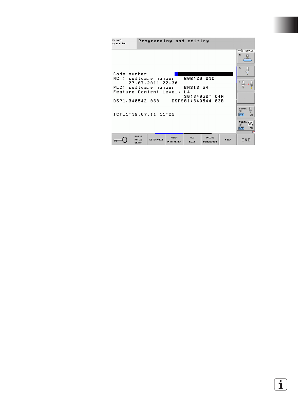
Display of the installed NC software and SKERN software
If you press the MOD key in any operating mode, the ID numbers and
versions of the installed software packages are displayed:
NC : software number: NC software with date
PLC : software number: PLC program
SG: SKERN software of the MC
DSPx: DSP software of CC number x
DSPSGx: SKERN software of CC number x
ICTLx: Current controller of CC number x
October 2011 1.2 NC Software 606 42x-01 SP 06 11
Page 12

12 HEIDENHAIN Technical Manual Functional Safety
Page 13

1 Update Information No. 03 – Functional Safety
1.1 Overview
1.1.1 Released service packs
The following service packs were released for 606 42x-01:
Service pack 01: August 2010
Service pack 02: December 2010
Service pack 03: February 2011
Service pack 04: March 2011 (not for functional safety)
Service pack 05: May 2011 (approved for functional safety)
Service pack 06: September 2011
(approved for functional safety)
The following software versions were released for applications with integrated
functional safety (FS):
606 42x-02: December 2011
March 2012 1.1 Overview 13
Page 14

1.2 NC Software 606 42x-02
Note
1.2.1 Important notes
Release of software
for FS applications
Until now you received a HEIDENHAIN Filebase Info when a new NC software
version or service pack was released for applications with integrated
functional safety (FS). The software could then be downloaded from the usual
directories for your control via HESIS-Web including Filebase (e.g. Controls/
iTNC 530/Software EXLREQ).
In order to improve the overview of which software versions have been
released for applications with integrated functional safety (FS), new directories
were created in HESIS-Web including Filebase. These directories have the
additional code "FS" in their name (e.g. Controls/iTNC 530/
Software FS EXLREQ). Once HEIDENHAIN has released the respective NC
software for applications with integrated functional safety, the NC software
will be stored in these new directories. Every software version that you find in
these FS directories has been released for applications with integrated
functional safety (FS). You will continue to be informed about released
software via HEIDENHAIN Filebase Infos. When downloading NC software
from one of the existing standard directories, you will be informed that these
software versions are not approved for use with integrated functional safety
(FS).
Controls using integrated functional safety (FS) from HEIDENHAIN are to
be operated only with software versions found in the HESIS-Web including
Filebase directories with FS in their names.
The same applies to Technical Manuals and Update Information documents
for functional safety. Starting immediately, these will also be in directories
identified with "FS" (e.g. Controls/iTNC 530/Documentation FS OEM).
PLC outputs Single-channel outputs (standard PLC outputs) configured as output type 3
(switch-off upon EMERGENCY STOP) with IOconfig until now were not
switched off automatically upon an emergency stop. The PLC program had to
switch the outputs off. With software version 02 these single-channel PLC
outputs will be switched off automatically when an external or internal
emergency stop is initiated. The outputs remain switched off until the
emergency-stop is rescinded and the control voltage has been switched back
on. Just rescinding the emergency-stop situation does not suffice to switch
these outputs back on.
14 HEIDENHAIN Technical Manual Functional Safety
Page 15
1.2.2 New splcapimarker.def definition file
Software version 606 42x-02 contains a slightly modified splcapimarker.def
definition file (version 56). However, the modifications are only preparatory
measures for future enhancements. In software version 02 they do not result
in any direct improvements of any functions. The number of possible axes was
raised from 18 to 22, which shifts the spindle index to 22. This change results
in a new memory layout of the SPLC run-time system, which necessitates a
new acceptance test. Version 55 of splcapimarker.def must be replaced by
version 56 after the software update.
Proceed as follows:
Replace the splcapimarker.def file:
During the update of the NC software, a new version of splcapimarker.def
was automatically copied to the PLC partition of the control.
Switch to the Programming and Editing operating mode.
Enter the MOD code number 807667 to switch to the PLC Programming
mode of operation.
Press the PGM MGT key to open the file manager.
Switch to the PLC:\proto\plc directory.
Copy splcapimarker.def to the program directory of your SPLC program.
Overwrite the existing splcapimarker.def file.
Change the entry in SMP693 for the new SPLC-API version to 56.
Put the change in SMP693 into effect after rebooting the control by using
the OEM password
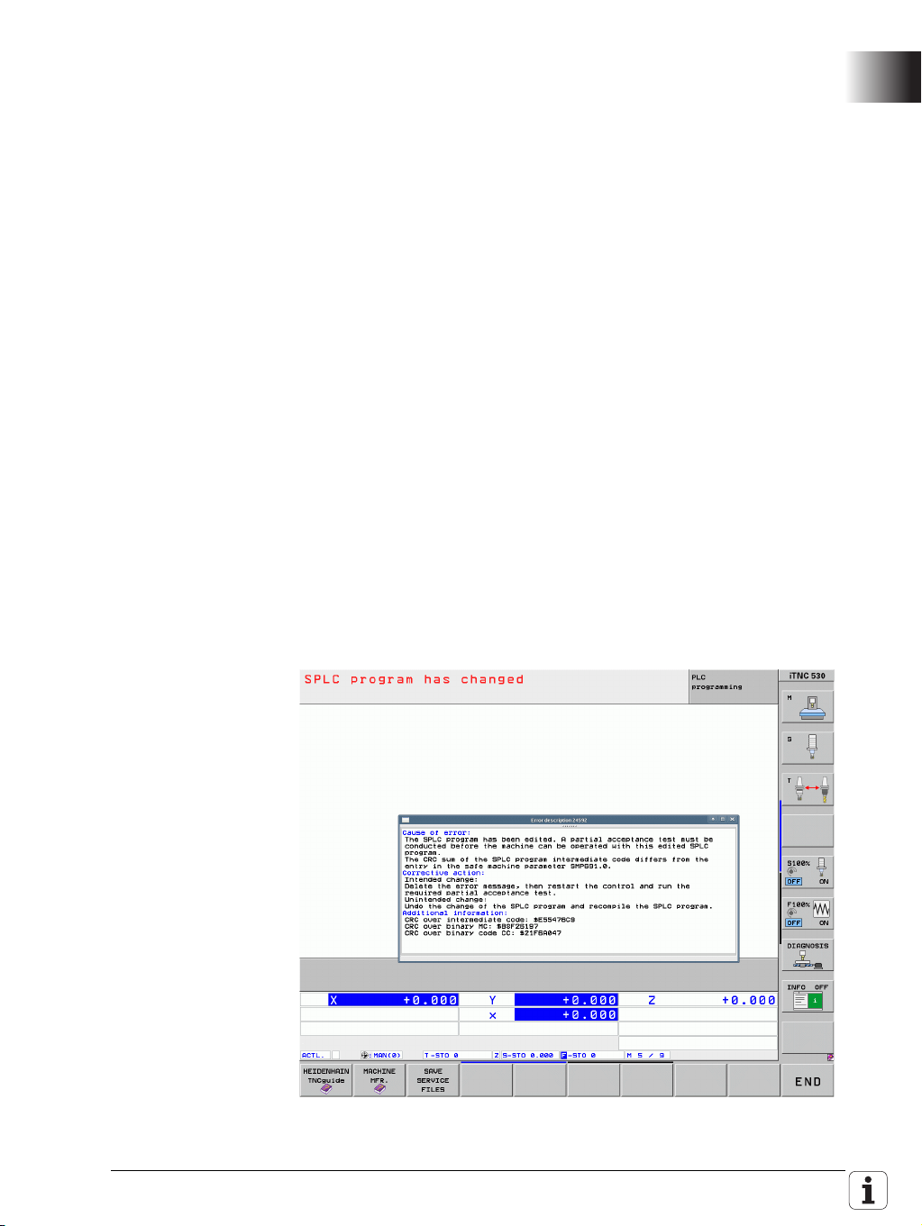
Check and compile the SPLC program with the new splcapimarker.def file.
The following message than appears, since the intermediate and binary
code of the SPLC program has changed:
March 2012 1.2 NC Software 606 42x-02 15
Page 16

Included in the message, under the heading "Additional information," are the
Note
Danger
new CRC checksums for the intermediate code, binary code MC and binary
code CC. Enter these values in SMPs 691.0, 691.1 and 691.2.
Put the changes in SMP691.x into effect after rebooting the control by using
the OEM password.
Please also copy the splcapimarker.def file to your PC as well, and add it to
the PLCdesignNT project. Otherwise, during the next transfer of SPLC
project files to the control, the file might be overwritten by the old version.
The SPLC-API programming interface can also be included in the standard PLC
program (INCLUDE). If this is the case, the data from ApiFromSafety and
ApiToSafety are copied to the double-word range of the PLC. This data can
then be used for additional interrogations or diagnostic purposes in the PLC
program.
Since the number of possible axes was raised from 18 to 22 (indexes 0 to 21),
the index of the first spindle is shifted to 22. Please take this into account in
your SPLC program, and make any necessary adjustments. So that you don't
always have to modify the SPLC program when there are such changes in the
future, HEIDENHAIN recommends using the constant FIRST_SPINDLE for the
spindle in the SPLC program.
You must subject the machine to a new acceptance test, as a consequence
of the changed SPLC-API version.
16 HEIDENHAIN Technical Manual Functional Safety
Page 17
1.3 New Safety Functions
Extended SPLC diagnostics
• A predefined watch list is available for the static diagnosis of the SPLC
markers defined in splcapimarker.def. It can be called from the PLC
diagnostics via the WATCH LIST soft key and the program manager
(PGM MGT key). The file can be found at: PLC:\DEBUG\SPLCAPI.WLT
• Under the DIAGNOSIS soft key in the PLC operating mode there is
another soft key: GENERATE TRACE FILES. Pressing it triggers the
generation of HSCI and SPLC trace files. These files (xxx.trace and
xxx.sco) are stored in the folder PLC:\DEBUG\.
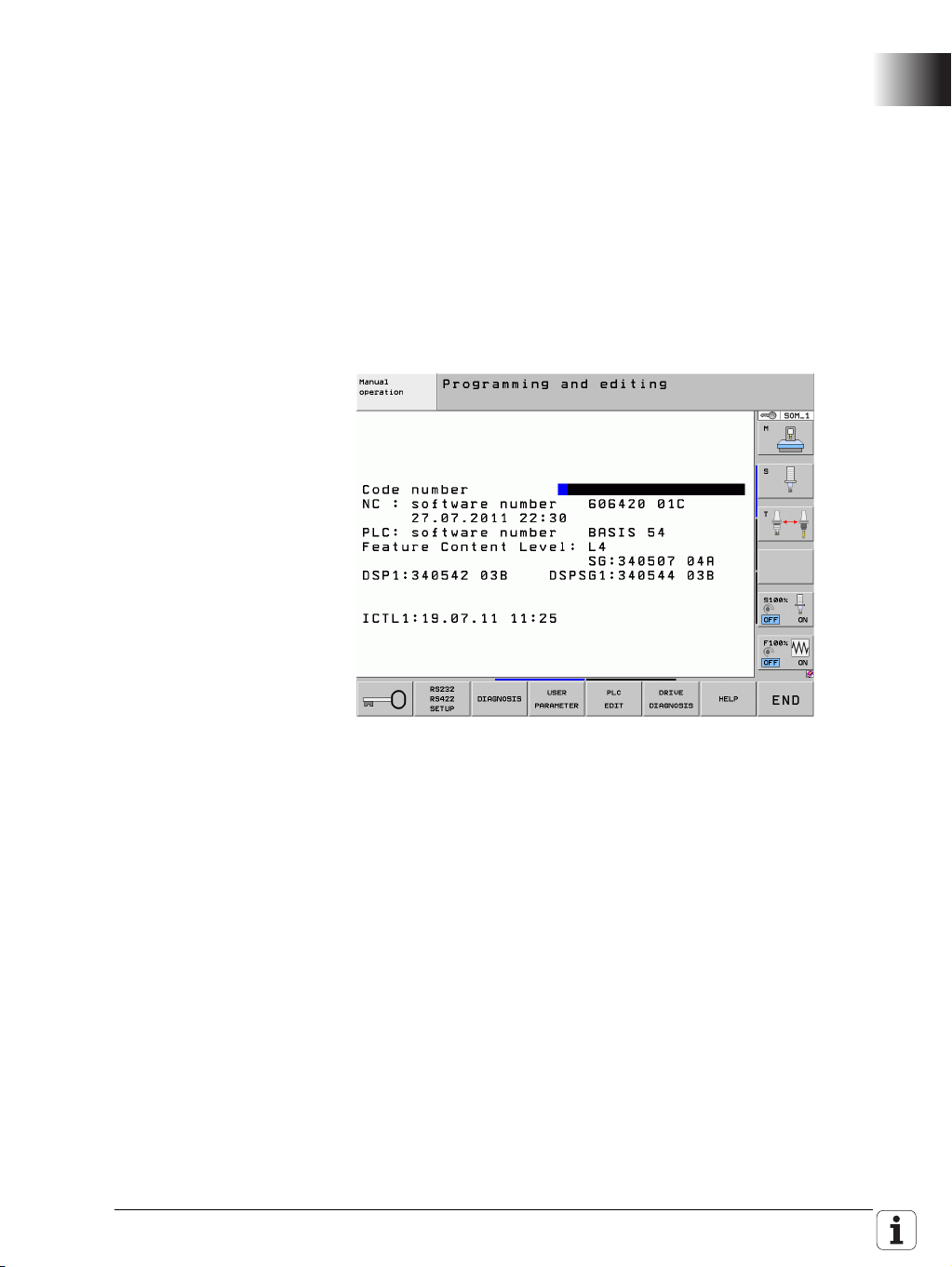
Display of the installed NC software and SKERN software
If you press the MOD key in any operating mode, the ID numbers and
versions of the installed software packages are displayed:
NC : software number: NC software with date
PLC : software number: PLC program
SG: SKERN software of the MC
DSPx: DSP software of CC number x
DSPSGx: SKERN software of CC number x
ICTLx: Current controller of CC number x
Standstill monitoring in SOS state
If, however, the maximum permissible path defined in SMP545.x (limit
value for standstill monitoring in [mm] or [°]) was exceeded while adhering
to the limit values for the spindle speed and axis feed rate in SOS, the SS0
safety function was initiated globally for all axes, and SS1 for the spindles.
Now an SS0 reaction is initiated for the affected drive (axis or spindle), and
an SS1F reaction for all other drives.
March 2012 1.3 New Safety Functions 17
Page 18

Standstill monitoring of the spindle with SS2
The new machine parameters SMP556, SMP557 and SMP558 can be used
to specify a maximum value for standstill monitoring of the spindle upon on
SS2 reaction. If the permitted number of spindle revolutions are exceeded
during the SS2 reaction, an SS1 reaction is initiated.
• SMP556 - Maximum value for standstill monitoring during SS2 of
spindle in SOM_2
Input: 1 to 100 [revolutions]
Default value = 2
• SMP557 - Maximum value for standstill monitoring during SS2 of
spindle in SOM_3
Input: 1 to 100 [revolutions]
Default value = 5
• SMP558 - Maximum value for standstill monitoring during SS2 of
spindle in SOM_4
Input: 1 to 100 [revolutions]
MP1310.x – Sequence for approaching the test positions
The axis sequence of the soft keys for approaching the test positions can
now be configured with MP1310. As previously, the operator can change
the sequence by selecting the soft keys. The parameter index determines
the position of the soft key in the soft-key row. The value of the parameter
defines the axis to be displayed in the soft-key image in reference to MP100.
All parameters after a programmed value 0 are not taken into consideration.
The remaining safe axes is shown in the same sequence as in MP100. If a
negative value is entered, the axis is shown in gray, and only becomes active
once the axes with positive entries have been moved to the reference point
or the operator selects the axis.
Example:
MP100: CBAaZYX
MP1310.0: 7
MP1310.1: 6
MP1310.2: -4
MP1310.3: 0
Soft-key row: C B a X Y Z A a=gray
Default value = 5
Input in MP1310.x:
1 to 18 [number indicating the axis' position in the test sequence]
0 = Not active
Displaying the distance-to-go during axis check
During the automatic movement of an axis in the "Check axis position" mode
to the test position, the distance-to-go display showed the distance
remaining to the software limit switch instead of the distance remaining to
the test position. Now, for approaching the test position and for incremental
jog, the distance remaining to the target is displayed.
Analog axes via CMA-H
As of software version 606 42x-02, analog axes can be configured and
operated via the CMA-H module. The integrated functional safety from
HEIDENHAIN does not monitor analog axes. Monitoring, switch-off, etc.
must occur through suitable external circuitry.
18 HEIDENHAIN Technical Manual Functional Safety
Page 19

SS1D when MP549 = 2 leads to SS2 with subsequent SOS of the axis
group
In case of an SS1D for an axis group (e.g., for the spindle when releasing the
permissive key while the door is open) the system until now waited until all
interlinked axis groups (SMP610.x) had terminated an active SS2 or SS1D.
Then all drives of the affected axis group (e.g., the spindle) were stopped
with an SS1. Until now this always led to removal of power from the axis
group (STO) for which the SS1D had been initiated.
As of NC software version 606 42x-01 SP 06, if SMP549.x = 2 is set, the axis
group (e.g., the spindle) for which an SS1D was initiated is braked with an
SS2 after the interlinked axis groups have been braked. At standstill SOS
becomes active for this axis group instead of STO. This means that in case
of an SS1D or SS2 at standstill, SMP549.x = 2 leads to the SOS state.
Please note that upon SS1D this function now initiates an SS2 stop reaction
for the affected axis group, and not an SS1 as previously.
SMP (iTNC 530): SMP549.x
Description: Axis-group-specific configuration defining whether
the axis group is to be switched to SOS instead of
STO upon an initiated SS1D or SS2 (e.g., spindle)
(used for lathes).
Input: 0: Default (spindle in STO, axes in SOS)
1: Axis group in STO upon SS1D or SS2
2: Axis group in SOS upon SS1D or SS2
Default value: 0
Protection against unexpected movement with SMP 549.x = 2
If SMP549.x = 2 for the axis group (including spindles), the axis group now
remains in the SOS state or under control in the following cases even while
at standstill. This means that there is no automatic transition to STO:
• if the permissive key or button is not pressed at standstill or while in the
SOS state.
• if the override potentiometers are at 0% when guard doors are opened.
• if M19 is active when guard doors are open (only for spindle axis group).
March 2012 1.3 New Safety Functions 19
Page 20
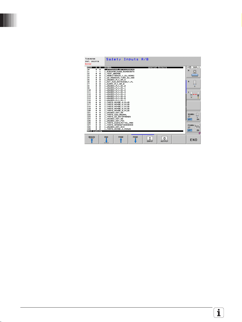
Diagnosis of the SPLC inputs and outputs
In the PLC programming mode (code number 807667) the last soft-key row
under the table function (TABLE soft key) has a soft-key called S-PLC
DIAGNOSIS. There you will find a list of all FS inputs and FS outputs, along
with their current state. The regular FS outputs as well as the "special"
outputs, such as TEST.A, TEST.B, STO.A.G and STOS.A.G, are also shown.
The table shows the operand address, the state of the A and B channel
inputs, and the symbolic name.
Fault reaction to safe status bits
Until now, if –PF.PS.DC was active, the watchdogs of the MC were not
retriggered. The other HSCI participants therefore detected the MC as being
defective, and it was not possible to switch off the DC-link voltage without
an error message. Until now the CC initiated an SS1 reaction. The SKERN
MC and CC now no longer evaluate the -PF.PS.DC status bit, and there is no
longer a reaction by the SKERN.
20 HEIDENHAIN Technical Manual Functional Safety
Page 21

1.4 (S)PLC
The PLC Module 9143 for triggering the brake test can now also be used in
systems with functional safety. The brake test during the safety self-test is not
affected by this, and continues to test the motor holding brake. It is now
possible, via this module and the (S)PLC program, regardless of the self-test,
to test the motor holding brakes at any time for specific axes, and even for
specific brakes of an axis. The module only tests the holding torque of the
brake, but not the dual-channel controllability of the brake. The dual-channel
controllability is still part of the self-test. The procedure for testing two brakes
of an axis via Module 9143 could be as follows:
The SPLC program controls the opening and closing of the brake
simultaneously for the motor holding brake and the supplementary brake
The SPLC program controls the opening and closing of the brake only for the
motor holding brake
The supplementary brake is opened
PLC Module 9143 performs the brake test for the motor holding brake
The SPLC program controls the opening and closing of the brake
simultaneously for the motor holding brake and the supplementary brake
The SPLC program controls the opening and closing of the brake only for the
supplementary brake
The motor holding brake is opened
PLC Module 9143 performs the brake test for the supplementary brake
The SPLC program controls the opening and closing of the brake
simultaneously for the motor holding brake and the supplementary brake
Module 9143 Activate the brake test
With this module an axis-specific brake test with the configuration from the
machine parameters or with other values for MPs 2230 and 2232 can be
started. Refer also to the information in the Technical Manual of your control.
Constraints:
Synchronized axes
For synchronized axes, only the brake test of the master can be configured
and requested via the PLC module. If a brake test for an associated slave
drive of the synchronized axis is configured via MP2230.x, then the slaves
are automatically tested together with the master. The settings in the
machine parameters are used for the brake test of the slave drives.
In order to start the brake test of synchronized axes via PLC Module 9143,
all drives of a synchronized axis must be switched on via the PLC program
before the brake test can be performed. If a servo drive involved is not
switched on, the brake test is canceled with the error message 8330 Brake
test was canceled.
Programming it in a submit job blocks other submit jobs until the test is
completed.
The PLC module automatically passes the processing time to other spawn
and submit processes.
March 2012 1.4 (S)PLC 21
Page 22
Call:
PS K/B/W/D <>Axis number>
0 = 1st axis, 1 = 2nd axis, etc.
PS K/B/W/D <>Multiplier for motor stall current>
Value in 1/1000 or
0: Default MP2230 (factor of nominal current)
PS K/B/W/D <>Permissible traverse path>
Value in 0.1 [um] or
0: Default MP2232
CM 9143
PL B/W/D <>Status/Error>
0: Brake OK
1: Brake defective
2: Invalid axis or negative values for rated current or traverse
path
3: Call during running NC program or during other PLC jobs
4: Call was made from a cyclic PLC program
5: Error during data exchange
6: Not allowed for safe control
7: Drive not ready
8: Brake test was canceled (e.g. by emergency stop)
Error recognition:
Marker Val ue Meaning
M4203 0 No error
1 Error code in W1022
W1022 2 Invalid axis programmed (invalid axis number, not a
closed-loop axis, axis currently open-loop axis or slave
axis) or negative values for the traverse path or current
are programmed
8 Module is not allowed for control with functional
safety
20 Module was not called in a spawn job or submit job
21 Call during program run or during other active PLC jobs
for the programmed axis
40 Drive not ready
45 Canceled due to error during data exchange or due to
external influences (e.g. emergency stop)
22 HEIDENHAIN Technical Manual Functional Safety
Page 23

Module 9037 Read FS status information
PLC Module 9037 determines safety-oriented information. The number of the
desired information, and possibly another number (for certain information)
must be programmed in the module.
Constraints:
Only for HSCI-based systems with SPLC can the time until the next self-test
be interrogated via number 4.
The causes for the stop reactions (number 7) are not stored statically. The
values are only set for the time in which the stop reaction occurs.
Call:
PS B/W/D/K/S<>Number of the status information>
0 to 3: Reserved
4: Time until the next self-test
5: Spindle speed at open guard door
6: Axis feed rate with open guard door
7: Stop reaction of axis group
PS B/W/D/K <>Number of the additional information>
For info 5: Spindle number starting with 0
For info 6: Axis number starting with 0
For info 7: Axis-group number starting with 0
CM 9037
PL B/W/D <>Type of operand>
0: Error
Response from the status information
For info 4: Time until the next self-test in seconds
For info 5: Spindle speed at open guard door in 0.001 [1/min]
For info 6: Feed rate with open guard door in 0.001 [mm/
min] or [°/min]
For info 7: Stop reaction of axis group
(0 = no stop reaction, 1 = SS2, 2 = SS1D, 3 = SS1,
4=SS1F, 5=SS0)
Error recognition:
Marker Valu e Meaning
M4203 0 No error
1 Error code in W1022 (also see return values of the
module)
W1022 1 Invalid number of the status information
2 Invalid number of the axis group, axis or spindle
43 The module was called in a control without integrated
functional safety
51 This status information is not supported by this
system
March 2012 1.4 (S)PLC 23
Page 24

24 HEIDENHAIN Technical Manual Functional Safety
Page 25

1 Update Information No. 04 – Functional Safety
Hinweis
1.1 Overview
1.1.1 Service packs released for the iTNC 530 HSCI
The following service packs for software version 606 42x-01 will be released
for applications with integrated functional safety (FS):
Service pack 02: April 2012
NC software 606 42x-02 service pack 01 was not approved for applications
with integrated functional safety (FS).
1.1.2 NC software versions released for the TNC 640
The following software versions were released for applications with integrated
functional safety (FS):
340 59x-01: April 2012
Controls using integrated functional safety (FS) from HEIDENHAIN are to
be operated only with software versions that are identified by FS in their
names in the HESIS-Web including Filebase directories of your control.
Software versions that are not identified by FS in their names in the HESISWeb including Filebase directories of your control are not approved for use
in applications with integrated functional safety (FS).
April 2012 1.1 Overview 25
Page 26

1.2 Notes
1.2.1 NC software 340 59x-01, 606 42x-02 SP 02
Protection against unexpected start-up
Up to now, the protection against unexpected start-up was disabled by
pressing a valid permissive button/key, which sets the interface signal
pp_AxGrpPB to 1. With software versions 340 59x-01 and 606 42x02 SP 02, the same behavior is enabled for the interface signal
pp_AxGrpActivate, which disables the activation of the protection against
unexpected startup if it is set to 1. As a result, the automatic transition to
SOS/STO state (transition from SLS --> SOS) is also prevented at feed rates
< 50 mm/min by merely pressing an axis key (pp_AxGrpActivate = 1).
SMP549.x is effective only for the axis group of the spindles
The setting in SMP549.x is effective only for the axis group of the spindles.
SMP549.x does not take effect for axis groups of NC or PLC axes.
SMP (iTNC 530): SMP549.x
Description: Axis-group-specific configuration defining whether
the axis group of the spindle is to be switched to SOS
instead of STO after SS1D or SS2 has been triggered
(used for lathes).
Input: 0: Default (spindle in STO, axes in SOS)
1: Axis group of the spindle in STO upon SS1D or SS2
2: Axis group of the spindle in SOS upon SS1D or SS2
Default value: 0
1.2.2 General information
Use of non-HEIDENHAIN encoders for safe axes/spindles for
Basic circuit diagram – leading main-switch contact
HEIDENHAIN control systems with functional safety (FS)
HEIDENHAIN cannot make any statement regarding the use of nonHEIDENHAIN encoders for the safe monitoring of axes/spindles in control
systems with functional safety (FS). Your contact person at HEIDENHAIN
will be glad to assist you in finding suitable HEIDENHAIN encoders for your
safe applications.
The leading main-switch contact that is proposed in the present
HEIDENHAIN basic circuit diagram is only intended for electrical protection
of the machine's main switch. The leading contact opens the main contactor
in the UV(R) before the main switch separates the connection to the power
line. This means that the main switch always separates the connection
while the system is not under power, even if the user accidentally switches
off the machine via the main switch while the drives are still in closed-loop
control. When using a leading contact, please keep in mind the associated
residual risks described in Chapter 4.11 of the Functional Safety (FS)
Technical Manual.
HEIDENHAIN merely wanted to point out that there is the possibility of
using a leading contact. However, you need not use a leading contact. It will
be omitted from the future versions of the basic circuit diagram. Without
this contact, the control behaves in the same way as during a power failure
when it is switched off via the main switch, i.e. the drives are decelerated
at the limit of current upon switch-off.
26 HEIDENHAIN Technical Manual Functional Safety (FS)
Page 27

1.3 NC software 340 59x-01 (TNC 640)
1.3.1 Notes
Missing functions The following functional safety (FS) functions are not contained in software
version 340 59x-01 of the TNC 640 in comparison with software version
606 42x-02 of the iTNC 530:
New "SPlcApiMarker.def version 56" definition file
The TNC 640 with software version 01 is still using SPlcApiMarker.def
version 55.
Standstill monitoring of the spindle upon SS2 (SMP556, SMP557,
SMP558)
Operating-mode-specific monitoring of the SS2 reaction of the spindle is not
yet possible with the TNC 640. In every SOM_x operating mode, the
TNC 640 uses the entry in SMP distLimitStop2 for SS2 monitoring of the
spindle.
Sequence for approaching the test positions
On the iTNC 530, the axis sequence of the soft keys for approaching the
test positions can be configured using MP1310. This is not yet possible on
the TNC 640 with software version 01.
Handwheels
The HR 5xx handwheels with display are not yet supported by software
version 01 of the TNC 6xx.
Software version 340 59x-01 of the TNC 640 is identical to software version
606 42x-02 of the iTNC 530 HSCI in all other functional safety (FS) functions.
SPLC program Please note that an SPLC program of the iTNC 530 needs to be modified for
use on the TNC 640. In particular, the spindle index in the SPLC program is
different. With the iTNC 530, the spindle is always assigned to the last index
(this is index 22 in SPlcApiMarker.def version 56). With the TNC 640, the
spindle is assigned to the index defined via axisList.
Documentation The previous Functional Safety (FS) Technical Manual for the iTNC 530 HSCI
was enhanced with regard to the TNC 640. This Technical Manual covers both
controls. Differences that need to be kept in mind are indicated in this Update
Information and in the Technical Manual (e.g. machine parameters of the
TNC 640 are identified by "NCK-SMP:".)
April 2012 1.3 NC software 340 59x-01 (TNC 640) 27
Page 28

28 HEIDENHAIN Technical Manual Functional Safety (FS)
Page 29
2 Introduction
Danger
Attention
Note
2.1 Meaning of the symbols used in this manual
Failure to comply with this information could result in most serious or fatal
injuries, and/or in substantial material damage.
Failure to comply with this information could result in injuries and
interruptions of operation, including material damage.
Tips and tricks for operation as well as important information, for example
about standards and regulations as well as for better understanding of the
document.
April 2012 2.1 Meaning of the symbols used in this manual 29
Page 30

2.2 Warnings
Danger
The functional safety as provided by HEIDENHAIN only handles the safety
functions stated and described in this manual. Functional safety can reduce
the inherent risks of machine tools. However, it is impossible to implement
safety measures that ensure that nothing will ever go wrong with a
machine tool.
In order for functional safety to take effect, the machine manufacturer must
do the following:
Verify the theoretical and actual setup of the machine tool, the necessary
(S)PLC programs and the machine-parameter settings with a thoroughly
documented acceptance test. This acceptance test must be performed
by qualified personnel.
Thoroughly understand the information contained in this manual and
other documentation for the control and other electronic components
being used (such as inverters and motors), as well as understand and
enforce the safety instructions, constraints and relevant standards.
Draw up a risk analysis, as required by the EC machinery directive.
implement all measures deemed necessary based on the risk analysis of
the machine. These measures may be implemented as a part of
functional safety, or with other suitable equipment or procedures. All
measures must be validated.
30 HEIDENHAIN Technical Manual Functional Safety (FS)
Page 31

Danger
Many safety-related machine parameters (SMP) and the safety-related PLC
Attention
program (SPLC program) are important for ensuring the safety of the
machine when it is controlled by an iTNC 530 or TNC 6xx with functional
safety.
Changing these safety-related machine parameters or the SPLC program
can result in loss of the machine safety as specified in the applicable
standards!
Safety-related machine parameters are therefore protected by a special
OEM password that is only known to the machine manufacturer.
Changes to the safety-related machine parameters and the SPLC program
may only be performed by trained personnel of the OEM. He is responsible
for the safety of the machine and compliance with the applicable standards,
in particular with EN 12417.
The HEIDENHAIN safety strategy cannot detect erroneous
parameterization or programming by the OEM. The necessary level of
safety can only be achieved with thorough acceptance testing of the
machine.
When exchanging a power module or motor, the same type must be used,
since otherwise the settings of the machine parameters could lead to
different reactions by the safety functions. If an encoder is exchanged, the
affected axis must be recalibrated.
Hardware components of the machine tool may only be exchanged by
trained personnel.
Prior to the initial operation or shipping of a machine tool, the
machine manufacturer must conduct a complete acceptance test.
All of the machine's safety functions must be tested. Furthermore, the
input values of the safety-related machine parameters and the entire SPLC
program must be checked for correctness.
If the SPLC program is changed subsequently, the entire acceptance
test must be repeated.
If individual machine parameters are changed subsequently, a partial
acceptance test is required.
Upon subsequent changes the safety functions affected by the respective
change must be tested. The changes and the necessary acceptance tests
may only be performed by trained personnel of the OEM.
April 2012 2.2 Warnings 31
Page 32

Attention
The machine tool is not in a safe state until after it has booted completely
and the safety self-test was passed successfully!
During start-up or the reset phase, the control is not in a safe state (e.g.
installation of a service pack). Axes and spindles are without torque
during this time!
When exchanging hardware components, also use the same model. If an
encoders is exchanged, then the motor affected must be referenced and
tested again.
Depending on the changes during an exchange or update of the
software, either a partial or complete acceptance test becomes
necessary. The following must be ensured before or during an exchange
or update of the software:
• All openings (e.g. doors) to the working space must be closed
• Emergency stop must be activated
• There must be no tools in the spindle
• Vertical axes must be protected against falling
• No persons are permitted in the danger zone
The control must be shut down correctly before the machine is switched
off via the main switch. Should this not be possible due to an error, an
emergency stop is to be triggered via the man switch before removing
power from the machine.
32 HEIDENHAIN Technical Manual Functional Safety (FS)
Page 33

2.3 Proper and intended operation
The described components may only be installed and operated as described
in this manual. Commissioning, maintenance, inspection and operation are
only to be performed by trained personnel.
HEIDENHAIN contouring controls and their accessories are designed for
integration in milling, drilling and boring machines, and machining centers.
2.4 Trained personnel
Trained personnel in the sense of this manual means persons who are familiar
with the installation, mounting, commissioning, and operation of the
HEIDENHAIN components. Furthermore, electrical engineering work on the
system may be carried out only by trained electrical engineering technicians or
persons trained specifically for the respective application.
Basically, persons who perform work on HEIDENHAIN components must
meet the following requirements:
They must have been trained or instructed in the standards of safety
engineering.
They must have appropriate safety equipment (clothing, measuring
systems).
They should be skilled in first-aid practice.
April 2012 2.4 Trained personnel 33
Page 34

2.5 General information
Danger
Only the following controls from HEIDENHAIN can currently be used for
Other controls (e.g. the TNC 6xx NCK-based controls) and NC software
Controls using integrated functional safety (FS) from HEIDENHAIN are to
Software versions that are not identified by FS in their names in the
Every machine tool operator is exposed to certain risks.
Although protective devices (safeguards) can prevent access to dangerous
points, the operator must also be able to work with the machine without this
protection (e.g. if the guard door is open).
Guidelines and regulations to minimize these risks have been developed
within the last few years.
applications with functional safety.
• iTNC 530 HSCI with the NC software 606 42x
• TNC 640 with the NC software 340 59x
versions do not support the use of functional safety!
be operated only with software versions that are identified by FS in their
names in the HESIS-Web including Filebase directories of your control.
Only these software versions are released by HEIDENHAIN for
application on control systems with functional safety.
HESIS-Web including Filebase directories of your control are not
approved for use in applications with integrated functional safety (FS).
34 HEIDENHAIN Technical Manual Functional Safety (FS)
Page 35

Machinery Directive 2006/42/EC obligates you as a machine-tool
manufacturer to perform detailed risk assessments in order to prove operator
safety during the various operating phases of the machine. The combination
of hazard analysis and risk evaluation leads to the determination of how much
risks must be reduced by design measures or control methods in order to
achieve an appropriate level of safety.
In accordance with EN 12417, the electronic controls of universal machines,
milling machines, lathes and machining centers must fulfill the requirements
of EN 13849-1 category 3 (previously EN 954-1) for their safety-related parts.
In particular this means that the control must be designed such that an
individual fault does not lead to loss of the safety function, and that any
individual fault is detectable if this is possible in an acceptable manner.
According to EN ISO 12100-1/2 (Safety of Machinery), it is important for safe
operation of the machine that the safety measures permit simple and
continuous use of the machine and that they do not impair its correct and
intended operation. If this is not the case, then this can lead to the safety
measures being circumvented in order to attain the simplest possible
operation of the machine.
The HEIDENHAIN safety strategy integrated in the iTNC 530 HSCI and
TNC 6xx complies with Category 3 as per EN 13849-1 and SIL 2 as per
IEC 61508, features safety-related operating modes in accordance with
EN 12417, and assures extensive operator protection.
The basis of the HEIDENHAIN safety concept is the dual-channel processor
structure, which consists of the main computer (MC) and one or more drive
controller modules (CC= control computing unit).
All monitoring mechanisms are designed redundantly in the control systems.
Safety-related system data is subject to a mutual cyclic data comparison, see
page 4–66.
Safety-related errors always lead to safe stopping of all drives through defined
stop reactions.
Defined safety functions are triggered and safe operating states are achieved
via safety-related inputs and outputs (in two channels) which have an influence
on the process in all operating modes.
April 2012 2.5 General information 35
Page 36

Additional
Note
Note
information
Documentation
This manual is a supplement to the Technical Manual of your control, and
describes the functions of the functional safety (FS) and the SPLC from
HEIDENHAIN. Therefore, please also refer to the following documentation:
• Technical Manual of your control
• "Inverter Systems and Motors" Technical Manual
• Online help of the PLCdesignNT development environment for (S)PLC
programming
Documentation of the hardware components
For the documentation of the iTNC 530 HSCI or TNC 6xx hardware
generation, please refer to your control's Technical Manual.
You can download manuals, other documentation and PC software tools for
machine manufacturers from the HESIS-Web including Filebase.
Specifics and constraints
The first software versions for functional safety do not include the full range
of features necessary to provide functional safety for all machine models.
Please see page 4–112. Your contact person at HEIDENHAIN will be glad to
answer any questions concerning the with functional safety on your control.
Before planning a machine with functional safety, please inform yourself of
whether the current scope of functional safety features suffices for your
machine design.
In practice, and in the sense of this document, a HEIDENHAIN control system
for a machine tool consists of:
a HEIDENHAIN NC control with integrated safety and HSCI, an MC main
computer and CC controller units
peripheral units such as screen, keyboard, machine operating panel and
handwheel
the SPL or PL assemblies with their I/O modules for connecting safety and
standard inputs and outputs
synchronous and asynchronous feed and spindle motors
position and speed encoders
supply modules and inverters
36 HEIDENHAIN Technical Manual Functional Safety (FS)
Page 37

A prerequisite for the functional safety of HEIDENHAIN controls is the
USB
HR xxx FS
MB 620 FS
TE 6xx
PL 62xx FS
MC 6xxx
HDL
HSCI
BF 2xx
Cabinet
Panel
PSL
Inverter
CC 6110
X79
(X112)
UVW
POWER MODULE
READY
RESET
UVW
Permissive Buttons,
Key Switches
Emergency Stop,
Door Contacts,
Relais
connection of the actual control components via the common HSCI
connection (HSCI = HEIDENHAIN Serial Controller Interface).
Figure 3.1: Possible setup of an HSCI system
April 2012 2.5 General information 37
Page 38

HEIDENHAIN control components for setting up a system with functional
safety:
Series Component of the control system
MC 6xxx, MC 7xxx MC main computer with HSCI interface for the
HEIDENHAIN NC control
CC 6xxx CC controller units with HSCI interface and
support for a variable number of control loops
PLB 6xxx FS Functional safety (FS) version of a bus module,
serves as carrier for several PLD-H xx-xx-xx (FS)
I/O modules. Designated SPL in this document.
PLD-H xx-xx-xx FS Functional safety (FS) version of an I/O module.
Designated SPLD in this document.
MB 6xx FS, MB 7xx FS Functional safety (FS) version of a machine
operating panel. Designated SMOP in this
document.
TE 6xx, TE 7xx Keyboard unit (ASCII keyboard, keys for
supporting the operator) without safety-relevant
tasks.
TE 6xx FS, TE 7xx FS Functional safety (FS) version of a keyboard unit
with an integrated MB 6xx FS machine operating
panel. The MB is designated SMOP in this
document.
HR xxx FS Functional safety (FS) version of an HR
handwheel.
BF xxx Screen with HDL connection.
Position and speed
encoders
UM 1xxD(W),
UVR 1x0D(W),
UV 130D, UR 2xxD,
UE 2xxD and UE 1xx
SIEMENSSIMODRIVE 611
HEIDENHAIN encoders with analog, EnDat 2.1
and EnDat 2.2 interface.
HEIDENHAIN power modules (UM), supply
modules (UV), regenerative supply modules
(UVR), inverter units (UE) and regenerative
inverters (UR).
The use of modules from Siemens'
SIMODRIVE 611 power module product family or
other non-HEIDENHAIN inverters has not been
approved for the integrated functional safety!
38 HEIDENHAIN Technical Manual Functional Safety (FS)
Page 39

The HEIDENHAIN safety strategy enables you to implement the protection
objectives defined in Directive 2006/42/EC easily and enjoy economic benefits
at the same time.
The following items may no longer be required:
Safety contactor combinations for emergency stop and guard door control
Time delay relays and auxiliary relays
Limit switch
Wiring effort
April 2012 2.5 General information 39
Page 40

2.6 Overview of FS components
Note
HSCI combines the communication between axis system and automation into
one bus system between control components. Along with simplifying the
connection technology, HSCI is also the basis for safe, dual-channel, digital
communication, which is the technical prerequisite for integrated safety
functions, referred to as "functional safety."
The following tables give an overview of the HSCI, FS and inverter
components of the control systems with functional safety. The individual
HEIDENHAIN components are described in your control's Technical Manual
and the Technical Manual for Inverters and Motors.
In systems with functional safety, certain hardware components assume
safety-relevant tasks. Approval for these components must be granted for
each variant individually by HEIDENHAIN. In the following table you will find
the basic ID number and variant for those hardware components that have
safety-relevant tasks.
The following lists, consisting of hardware components and their variants,
contain all hardware components that may be used in systems with
functional safety.
In HSCI systems with integrated functional safety (FS) you may use only
devices or variants that have been certified for use in such systems.
Please take the following lists into account when configuring your machine
and in case servicing is required. The right-most table column contains the
approved ID numbers of these components.
40 HEIDENHAIN Technical Manual Functional Safety (FS)
Page 41

2.6.1 List of approved control components
Note
In systems with functional safety, certain hardware components assume
safety-relevant tasks. Approval for these components must be granted for
each variant individually by HEIDENHAIN. In the following table you will find
the basic ID number and variant for those hardware components that have
safety-relevant tasks.
Systems with FS may consist of only those safety-relevant components for
which the variant is listed in the table below (e.g. xxx xxx-03).
Components indicated in this list with -xx do not assume any safety-relevant
task in the sense of functional safety (FS). You can use any variant of these
components.
Components indicated in this list with "Not yet approved for FS" are not
approved for use in systems with functional safety.
The list will be expanded or revised correspondingly when new components
are approved for use in systems with functional safety (FS). Should a
component you wish to use not be listed, please ask your contact person at
HEIDENHAIN if the component may be used.
Hardware component ID
MC 6241 Main computer 1.8 GHz with HDR, electrical cabinet version,
without Profibus
MC 6241 Main computer 1.8 GHz with HDR, electrical cabinet version,
with Profibus
MC 6222 Main computer with 15-inch TFT display, 1.8 GHz with SSDR,
operating-panel version, without Profibus
MC 6222 Main computer with 15-inch TFT display, 1.8 GHz with SSDR,
operating-panel version, with Profibus
MC 6341 Main computer with 15-inch TFT display, 2.2 GHz dual core with
HDR, electrical-cabinet version
MC 6341 Main computer with 15-inch TFT display, 2.2 GHz dual core with
HDR, electrical-cabinet version, with Profibus
573398-03
653220-03
634109-02
634113-02
Not yet
approved for FS
Not yet
approved for FS
BF 250 15-inch TFT display with HDL connection 599916-xx
BF 260 19-inch TFT display with HDL connection 617978-xx
BF 750 15-inch TFT display with HDL connection 785080-xx
BF 760 19-inch TFT display with HDL connection 732589-xx
CC 6106 Controller unit for HSCI for max. 6 control loops 662636-01
CC 6108 Controller unit for HSCI for max. 8 control loops 662637-01
CC 6110 Controller unit for HSCI for max. 10 control loops 662638-01
April 2012 2.6 Overview of FS components 41
Page 42

Hardware component ID
UEC 111 Controller unit with inverter and PLC, 4 control loops 625777-xx
UEC 112 Controller unit with inverter and PLC, 5 control loops 625779-xx
UEC 111 FS Controller unit with inverter and PLC, 4 control loops, functional
safety
UEC 112 FS Controller unit with inverter and PLC, 5 control loops, functional
safety
UMC 111 FS Controller unit with inverter and PLC for power supply via
external DC link, 4 control loops, functional safety
CMA-H 04-04-00 SPI expansion module for analog nominal-value outputs 688721-xx
Not yet
approved for FS
Not yet
approved for FS
664231-02
PSL 130 Low-voltage power supply unit, 750 W, for +24 V NC and +24 V
PLC
PSL 135 Low-voltage power supply unit, 750 W, for +24 V NC, +24 V
PLC and +5 V NC
If other low-voltage power supply units are used for +24 V NC
and +24 V PLC, the output voltages must fulfill the
requirements for Protective Extra Low Voltage (PELV) with
double basic insulation according to EN 50 178, also see the
Technical Manual, Chapter 3.8.
MS 110 Mounting case for multi-row configuration 658132-xx
MS 111 Mounting case for multi-row assembly, additional connection
for 24 V supply to the fan
TE 620 Keyboard unit without touchpad 625806-xx
TE 720 Keyboard unit without touchpad 805488-xx
TE 630 Keyboard unit with touchpad 617976-xx
TE 730 Keyboard unit with touchpad 805489-xx
TE 740 Keyboard unit with touchpad 886546-xx
TE 635Q FS TE with touchpad and integrated MB for HSCI connection,
functional safety
TE 735 FS TE with touchpad and integrated MB for HSCI connection,
functional safety
TE 645Q FS TE with touchpad and integrated MB for HSCI connection,
functional safety (19-inch)
TE 745 FS TE with touchpad and integrated MB for HSCI connection,
functional safety (19-inch)
575047-xx
627032-xx
673685-xx
662255-01
805493-01
685394-01
805482-01
MB 620 FS Machine operating panel for HSCI connection, functional safety 660090-01
MB 720 FS Machine operating panel for HSCI connection, functional safety 805474-01
PLB 6001 FS HSCI adapter for OEM-specific machine operating panel,
functional safety
42 HEIDENHAIN Technical Manual Functional Safety (FS)
Not yet
approved for FS
Page 43

Hardware component ID
HR 410 FS Portable electronic handwheel with cable connection 337159-11,
578114-03
HR 520 FS Portable electronic handwheel with cable connection and
display
HR 550 FS Portable electronic handwheel with wireless transmission and
display
HRA 551 FS Handwheel adapter with integrated charger 731928-01
HRA 550 FS Handwheel adapter with integrated charger 633108-02
PLB 6104 PLB for HSCI, 4 slots 591828-xx
PLB 6106 PLB for HSCI, 6 slots 630058-xx
PLB 6108 PLB for HSCI, 8 slots 630059-xx
PLB 6204 PLB for HSCI, 4 slots, with system module 591832-xx
PLB 6206 PLB for HSCI, 6 slots, with system module 630054-xx
PLB 6208 PLB for HSCI, 8 slots, with system module 630055-xx
PLB 6104 FS PLB for HSCI, 4 slots, functional safety 590479-03
PLB 6106 FS PLB for HSCI, 6 slots, functional safety 804755-01
PLB 6108 FS PLB for HSCI, 8 slots, functional safety 804756-01
PLB 6204 FS PLB for HSCI, 4 slots, with system module, functional safety 586789-03
PLB 6206 FS PLB for HSCI, 6 slots, with system module, functional safety 622721-03
PLB 6208 FS PLB for HSCI, 8 slots, with system module, functional safety 620927-03
PLD-H 16-08-00 PL for PLB 6xxx: 16 digital inputs, 8 digital outputs 594243-xx
PLD-H 08-16-00 PL for PLB 6xxx: 8 digital inputs, 16 digital outputs 650891-xx
PLD-H 08-04-00 FS
PLD-H 04-08-00 FS
PLA-H 08-04-04 PL for PLB 6xxx, eight +/- 10 V inputs, four +/- 10 V analog
PL for PLB 6xxx FS: 8 digital inputs, 4 digital outputs, functional
safety
PL for PLB 6xxx FS: 4 digital inputs, 8 digital outputs, functional
safety
outputs, and four PT 100 inputs
670304-01,
670305-01
598515-02,
606622-02
598905-01,
598905-02
727219-02
675572-xx
If other low-voltage power supply units are used for +24V NC
and +24V PLC, the output voltages must fulfill the requirements for Protective
Extra Low Voltage (PELV) with double basic insulation according to EN50178,
also see the Technical Manual, Chapter 3.8.
April 2012 2.6 Overview of FS components 43
Page 44

2.6.2 List of approved inverter components
Danger
In HSCI systems with integrated functional safety (FS) you may use only
inverters or power supply modules that have been approved for use in such
systems.
Please take this into account when configuring your machine and in case
servicing is required. Suitable devices are listed below in the right column of
the table.
Components indicated in this list with "Not yet approved for FS" are not yet
approved for use in systems with functional safety.
The list will be expanded or revised correspondingly when new components
are approved for use in systems with functional safety (FS). Should a
component you wish to use not be listed, please ask your contact person at
HEIDENHAIN if the component may be used.
Below you will find an overview of the devices that—according to
ISO 13849-1—are permitted for use in systems with FS:
Hardware component Device ID for systems
Inverter modules
UM 117DW Not yet approved for FS
UM 116D Not yet approved for FS
UM 116DW Not yet approved for FS
UM 115D 671566-01
UM 114D 671288-01
UM 113D 730435-01
UM 112D 731984-01
UM 122D 667633-01
UM 121BD 667942-01
UM 111BD 671968-01
UM 121D 667838-01
UM 111D 667945-01
Power supply modules
UVR 120D 728252-01
UV 130D Not yet approved for FS
UVR 130D 728248-01
UVR 140D 728253-01
UVR 150D 728255-01
UVR 160D 728257-01
UVR 160DW 728258-01
UVR 170DW Not yet approved for FS
UVR 170D Not yet approved for FS
with integrated FS
44 HEIDENHAIN Technical Manual Functional Safety (FS)
Page 45

Hardware component Device ID for systems
with integrated FS
Non-regenerative compact inverters
UE 210D Not yet approved for FS
UE 211D Not yet approved for FS
UE 212D Not yet approved for FS
UE 230D Not yet approved for FS
UE 240D Not yet approved for FS
UE 241D Not yet approved for FS
UE 242D Not yet approved for FS
UE 110 Not yet approved for FS
UE 111 Not yet approved for FS
UE 112 Not yet approved for FS
Regenerative compact inverters
UR 242D Not yet approved for FS
UR 230D Not yet approved for FS
UR 240D Not yet approved for FS
April 2012 2.6 Overview of FS components 45
Page 46

2.6.3
Note
Differences between systems with and without functional safety (FS)
With the following HSCI control components, you must make a distinction
between those that are required in a system with functional safety and those
that can be used in a system without functional safety. Devices with FS are
listed below in the middle column:
Please refer to the lists of components approved for FS.
Device designation Device ID for systems
with integrated FS
Machine operating panels and keyboard units
In systems with FS you must use a machine operating panel for functional-
safety applications. In these operating panels, all keys have twin channels. A
movement can therefore be executed without additional permissive button/
key.
MB 620 (FS) 660090-xx 617973-xx
TE 635Q (FS) 662255-xx 617975-xx
TE 645Q(FS) 685394-xx 682104-xx
MB 720(FS) 805474-xx 784803-xx
TE 735(FS) 805493-xx 771898-xx
TE 745(FS) 805482-xx 679817-xx
PLB basic modules
In FS systems, mixed use of PLB basic modules with and without FS is possible.
However, at least one PLB 62xx FS must be used in systems with FS.
PLB 6104 (FS) 590479-xx 591828-xx
PLB 6106 (FS) 804755-xx 630058-xx
PLB 6108 (FS) 804756-xx 630059-xx
PLB 6204 (FS) 586789-xx 591832-xx
PLB 6206 (FS) 622721-xx 630054-xx
PLB 6208 (FS) 620927-xx 630055-xx
PLB 6001 (FS) Not yet available 668792-xx
PLD-H I/O modules
In systems with FS, the mixed use of PLD-H modules with and without FS is
possible in PLB basic modules with FS. However, do not insert PLD-H
modules with FS in PLB basic modules without FS. Furthermore, the
modules with FS must always be inserted into the PLB with FS starting from
the left.
PLD-H 16-08-00,
PLD-H 08-04-00FS
PLD-H 08-16-00,
PLD-H 04-08-00FS
598905-xx 594243-xx
727219-xx 650891-xx
Device ID for systems
without integrated FS
46 HEIDENHAIN Technical Manual Functional Safety (FS)
Page 47

Device designation Device ID for systems
with integrated FS
Handwheels
In FS systems, handwheels with cross-circuit proof permissive buttons must
be used. Handwheels for which this has been implemented are identified
with FS.
HR 410(FS) 337159-xx,
578114-xx (with detent)
HR 520 (FS) 670304-xx,
670305-xx (with detent)
Device ID for systems
without integrated FS
296469-xx,
535220-xx (with detent)
670302-xx,
670303-xx (with detent)
April 2012 2.6 Overview of FS components 47
Page 48

48 HEIDENHAIN Technical Manual Functional Safety (FS)
Page 49

3 Directives and standards
3.1 Applicable directives
Compliance with the following directives is mandatory for the design of
machine tools:
Directives Applicable since
Machinery Directive 2006/42/EC 29.12.2009
EMC Directive 2004/108/EC 20.07.2007
Low Voltage Directive 2006/95/EC 16.01.2007
HEIDENHAIN controls with integrated safety strategy fulfill their share of the
requirements as specified in the above directives, thus enabling you as the
manufacturer to produce your machines in accordance with the machinery
directives.
HEIDENHAIN controls with integrated functional safety (FS), for which safetyrelevant specifications (suitability for certain PL or SIL levels) will be indicated
in the future, are not considered safety components in the sense of Machinery
Directive 2006/42/EC (article 2, letter c). Since these controls are also not
"partly completed machinery" (article 2, letter g), they do not fall under the
provisions of the Machinery Directive. For this reason we do not issue any EC
Declaration of Conformity nor a Declaration of Incorporation in the sense of
the Machinery Directive.
April 2012 3.1 Applicable directives 49
Page 50

3.2 Basis for testing
The safety functions described as well as the devices for controls with
functional safety (FS) are tested by TÜV Süd. The directives and standards
serving as the basis for testing are listed below:
European directives
Directives Applicable since
Machinery Directive 2006/42/EC 29.12.2009
EMC Directive 2004/108/EC 20.07.2007
Low Voltage Directive 2006/95/EC 16.01.2007
Functional safety
Safety standards Requirement Meaning / Designation
DIN EN 61508-1 to 4
(2001)
EN 954-1 (1996) Cat 3 Safety of Machinery – Safety-
DIN EN ISO 13849-1
(2008)
Due to the applications of the device or system, the following directives and
standards are also valid:
Safety standards Meaning / Designation
IEC 61800-5-2 (FDIS) (2006) Adjustable Speed Electrical Power
DIN EN 60204-1 (2007) Safety of Machinery – Electrical
SIL 2 Functional Safety of Electrical/
Electronic/Programmable
Electronic Safety-Related
Systems
Related Parts of Control
Systems
Cat 3 / PL d Safety of Machinery – Safety-
Related Parts of Control
Systems
Drive Systems – Part 5-2: Safety
Requirements – Functional
Equipment of Machines – Part 1:
General Requirements
50 HEIDENHAIN Technical Manual Functional Safety (FS)
Page 51

Primary safety
Safety standards Meaning / Designation
DIN EN 50178 Electronic Equipment for Use in Power
Installations
Electromagnetic compatibility
Safety standards Meaning / Designation
DIN EN 61800-3 EMC product standard including
specific test methods for electrical
power drive systems
"EMC and functional safety for power drive systems with integrated safety
functions" principle for testing dated February 2007
April 2012 3.2 Basis for testing 51
Page 52

Requirements of
IEC 61508 SIL 2
The goal is to control or avoid errors in the control, and to limit the probability
of dangerous failures to defined values. Safety integrated levels (SIL) have
been defined to measure the achieved level of safety-related performance.
The entire system, including all associated components, must achieve the
required safety integrated level. For systems with programmable electronics,
the SIL capability and the limited failure rate PFH (probability of dangerous
failure per hour) result from applying IEC 61508 during the development and
manufacture of these systems.
A safety integrated level corresponds to a defined range of probability for the
dangerous failure of safety functions. By achieving SIL 2, which the
HEIDENHAIN controls with functional safety do, the probability of failure of
the safety functions is between 10
-6
and 10-7 failures per hour.
Requirements
of EN 13849-1
Category 3,
Performance
Level d
Fulfillment of the
requirements
The EN 13849 standard (previously EN 954) is of special importance.
This standard groups the requirements for safety-related control components
into categories (B, 1, 2, 3, 4) and performance levels (a, b, c, d, e) in ascending
degrees of safety-related effectiveness.
Category B must always be fulfilled. It requires the following:
In accordance with the applicable standards, the design of safety-related parts
of machine controls and their safeguards must ensure that they can withstand
the influences to be expected.
To attain category 3, the occurrence of an individual fault must not result in the
loss of the safety function. The system must reliably detect individual faults.
The safety function must always remain in effect if an individual fault occurs.
The performance level determines the capability of the safety-related parts of
the control to perform a safety function. Performance Level d corresponds to
SIL 2 of IEC 61508 (see above), but is determined using a risk graph.
HEIDENHAIN controls with functional safety operate according to the
following principles in order to fulfill the requirements for category 3:
The control is structured in such a way that individual faults are detected, and
that an individual fault in the control does not result in loss of the safety
function.
Redundant structures, reciprocal data comparison and dynamic sampling of
safety-related signals are used for error detection.
The principles below are followed in order to fulfill the requirements of SIL 2:
In order to avoid faults in safety-related software, HEIDENHAIN adheres to
annexes A and B of IEC 61508-3.
Tables A.2 to A.15 and A.16 to A.19 of IEC 61508-2 are used to control random
faults and to avoid systematic faults.
52 HEIDENHAIN Technical Manual Functional Safety (FS)
Page 53

3.3 Requirements on safety integrity
3.4 SIL and target failure measures
A complete system from HEIDENHAIN, consisting of control, encoder and
drive, fulfills SIL 2. This corresponds to a PFH_total (probability of dangerous
failure per hour) of 10
Summary of the fulfilled safety categories and levels for the safety functions
described in this manual:
Complete system: SIL 2 and category 3
PFH_total: 10-7 to 10
Performance level: d
The safety functions and hardware components for functional safety (FS) are
certified by independent institutes. Upon request, your contact partner at
HEIDENHAIN can provide you with the safety-related characteristic values
needed for calculations as per EN ISO 13849-1.
-7
to 10-6.
-6
3.5 Storage and operating temperatures
The limit values for the individual HEIDENHAIN components are stated in your
control's Technical Manual.
3.6 Limit values for EM noise immunity
According to the current standards, safety related power drive systems with
integrated safety functions, abbreviated as PDS(SR), must have an increased
noise immunity to electromagnetic phenomena (electromagnetic compatibility
(EMC)). HEIDENHAIN complies with the limit values specified in the "EMC and
functional safety for power drive systems with integrated safety functions"
principle for testing dated February 2007. This specification is used when
testing and certifying the HEIDENHAIN control systems with integrated
safety.
3.7 Mission time
An average life of 20 years is assumed for these controls.
April 2012 3.7 Mission time 53
Page 54

54 HEIDENHAIN Technical Manual Functional Safety (FS)
Page 55

4 Realization and safety functions
4.1 Glossary
A channel and B
channel
STL Statement list of the (S)PLC program
API Application programming interface
CC Controller computer:
Master CC Master controller computer:
All safety-related areas of the control (hardware and
software) have a dual-channel design. The two channels
are designated as the A channel and B channel.
Areas covered by the A channel are colored blue in this
document.
Areas covered by the B channel are colored red in this
document.
Interface between the (S)PLC program and the
respective safety-kernel software (SKERN MC, SKERN
CC) or the standard functions of the NC software
Modular HSCI slaves, for servo drive control
CCs also assume safety-related tasks (see SPLC/
SKERN below). The MC determines the master CC on
the basis of the relative positions in the HSCI system.
The first CC in the HSCI system (nearest the MC)
becomes the master CC.
Modular HSCI slaves, for servo drive control
In a safety-related control system, the master CC alone
assumes the following special tasks in addition to the
usual tasks of every CC:
Represents the B channel of a safety-related control
system
Generates the output states of the SPLC of the B
channel (for the safety-related outputs on the SPL),
such as the outputs for controlling the brakes
Monitors the controlling of the motor holding brakes
of the B channel (via power module or SPLC) and the
disabling of power modules for all axes in the system
Supplies the B-channel data for cross comparison
Supplies the actual position values for the SPLC
April 2012 4.1 Glossary 55
Page 56

CC-CC
communication
FPGA Field programmable gate array:
HDL HEIDENHAIN display link:
HR Handrad HR (German) = Handwheel HW
HSCI HEIDENHAIN serial controller interface:
Special HSCI telegram for exchanging the following
data between two or more CCs:
States of the individual axes (at standstill or in motion)
Axis-group assignment
Actual position values of the axes
Status of brake control
Status of the axis-specific cutout ports of the B
channel
Information about fatal fault
Freely programmable logic circuit
HDL is a data connection between the MC and the
screen/keyboard
Handwheel for operating the machine
HSCI is a field bus system that is based on Ethernet
hardware and has a line structure according to the
master-slave principle. There is one master in the
system; all other devices are slaves. All data transfers
are initiated by the master; however, direct
communication between the slaves is also possible.
IOC file Configuration file of the HSCI system:
Configuration of all participants in the HSCI system,
their sequence and configuration of the inputs and
outputs of the (S)PLC
LIFT-OFF Function that lifts off the tool automatically from the
contour by a defined distance in the tool-axis direction
in order to protect the workpiece (e.g. in a power
failure).
MC Main computer:
Control hardware that also functions as a master for
HSCI
PLC Programmable logic control:
The main task of the PLC program is the processing of
the input information from the PLs and the generation
of output states for the PLs (see page 4–60)
SKERN Safety-kernel software:
The software process of the safety-kernel software
(SKERN) runs in parallel to the SPLC. Basic safety
functions are permanently defined in the SKERN
software and cannot be changed (see page 4–63).
56 HEIDENHAIN Technical Manual Functional Safety (FS)
Page 57

SMOP Safe machine operating panel:
The (safety-related) machine operating panel is an HSCI
slave to which safety-related keys for controlling a
machine tool are attached and to which further (safetyrelated) inputs/outputs are connected (see page 6–186).
The safety-related data is transmitted from the SMOP
to the MC and CC over two channels via the HSCI
connection. The safety-related data is transferred from
there to the respective SPLC.
SPLC Safe programmable logic control:
The main task of the SPLC program is the processing of
the input information from the SPLs and the generation
of output states for the SPLs. This can be configured
flexibly using the SPLC program.
(see page 4–61)
SPL and PL (Safe) programmable logic unit:
A PL is an HSCI slave equipped with multiple I/O
modules. Each I/O module provides digital ((S)PLD) and/
or analog (PLA) inputs and/or outputs (I/Os). These I/Os
are read and controlled by the PLC and SPLC during
normal operation (see page 4–61).
An SPL is a dual-channel PL, which is equipped with
controllers for the A channel and the B channel. The
safety-related data is transmitted from the SPL to the
MC and CC over two channels via the HSCI connection.
The safety-related data is transferred from there to the
respective SPLC.
A safety-related control generally uses both SPLs and
single-channel PLs. Safety-functions require the use of
SPLs.
An (S)PL is structured as follows:
Bus module
All (S)PLs have a bus module. The bus module can
have only one controller (for the A channel), or two
controllers (for the A channel and the B channel) in the
case of a control with integrated safety.
System module
A system module has control-specific
I/Os and connections for touch probes. At least one
system module is present in every system.
I/O module – (S)PLD, PLx
One S(PL) has slots for four, six or eight I/O modules.
Both (safety-related) digital ((S)PLD) I/Os and, for
example, analog (PLA) I/Os can be inserted.
System PL
SPL with system module
April 2012 4.1 Glossary 57
Page 58

SPLD and PLD One SPL or PL has slots for four, six or eight digital I/O
modules.
A safety-related control generally uses both SPLDs and
single-channel PLDs. Safety-functions require the use
of SPLDs.
FS inputs,
FS outputs
(S)MP (Safety) machine parameters:
S status Safe status range of the HSCI telegram. The safe status
TM Tool magazine:
SSt Safety self-test:
WD Watchdog:
Safety-related dual-channel inputs/outputs. One FS
input/output consists of two physical terminals.
Parameters for adapting the control to the respective
machine tool (see page 5–119)
range contains bits for the status of watchdogs,
emergency stop and power-fail information, etc. of the
individual HSCI participants. The bits of the safe status
range provide the basic safety-related information of the
A channel (see page 4–98).
Tool magazine for the storage and management of
different tools
Safety self-test (see page 7–191)
Counter for monitoring the status of other functions or
components
58 HEIDENHAIN Technical Manual Functional Safety (FS)
Page 59

4.2 Realization of the HEIDENHAIN safety system
The dual-channel safety system of HEIDENHAIN controls is achieved by a
dual-channel control architecture. The two computers are located in the MC
main computer and CC controller unit components, where two independent
software processes run. These two processes realize two safety channels,
which capture and evaluate all safety-relevant signals in the two channels.
Faults are detected by mutual comparison of the states and data (cross
comparison) in the two channels. This way, the occurrence of just one fault in
the control does not lead to the safety functions being incapacitated.
The SPLC (safety-related PLC) and SKERN (safety-kernel software) software
processes are the basis of the two redundant channels. The two software
processes run on the MC (CPU) computer and the CC (DSP) controller unit
computer.
The dual-channel structure of the MC and CC is also used in the PL 6xxx FS
input/output systems and the MB 6xx FS machine operating panel. This
means that all safety-relevant signals (e.g. permissive buttons and keys, door
contacts, emergency stop button) are captured via two channels, and are
evaluated independently of each other by the MC and CC. The MC and CC use
separate channels to address the power modules, and to stop the servo drives
in case of a fault.
Furthermore, HEIDENHAIN controls with functional safety offer four safetyrelated operating modes as per the EN 12 417 standard (Machine Tools–
Safety–Machining Centers). The application-oriented operation offered by this
promises a high level of acceptance, and therefore safety.
4.3 Activation of functional safety (FS)
Functional safety is not a software option that must be enabled. If the control
identifies a PLB 62xxFS in the HSCI system during booting, functional safety
is activated. In this case, the following prerequisites must be fulfilled:
Functional safety versions of safety-related control components (e.g.
MB 620FS, HR 520FS)
Safety-related SPLC program
Configuration of safe machine parameters
Wiring of the machine for systems with functional safety
April 2012 4.3 Activation of functional safety (FS) 59
Page 60

4.4 (S)PLC programs
MC 6xxx
CC 6xxx
Channel B
Channel A
DSP
CPU
HSCI interface
HSCI interface
Cross
comparison
The main task of the (S)PLC program is the processing of the input information
from the (S)PLs and the generation of output states for the (S)PLs.
To do so, it edits the PLC memory via PLC commands with memory operands.
Logical states and signed bytes, words (16 bits) and double words (32 bits) are
saved in this memory.
Specific areas have different tasks:
Memory mapping the status of the inputs
Memory for timers and counters
Memory for internal states and calculations
Memory for the interface to the software of the MC and CC
Memory defining a map of the outputs to be set
This division of the memory is also called a memory map.
On a control with integrated safety, three different PLC programs with
separate memory maps are run simultaneously:
Standard PLC program on the hardware of the MC
SPLC program on the hardware of the MC
SPLC program on the hardware of each CC
60 HEIDENHAIN Technical Manual Functional Safety (FS)
Figure 3.2: SKERN and SPLC
Page 61

4.5 SPLC
The safe PLC program (= SPLC program), the PL 6xxx FS (= SPL) input/output
modules and the MB 6xx FS (= SMOP) machine operating panel provide the
machine tool builder with a flexible configuration of the safety system. The
SPLC consists of the SPLC runtime system and the SPLC program. The SPLC
runtime system is part of the software supplied by HEIDENHAIN. It executes
the SPLC program that must be written by the machine tool builder. The
safety-related inputs and outputs as well as additional safety functions can be
programmed flexibly in the SPLC program. The SPLC is also responsible for
the import and processing of FS inputs, as well as for the output of FS outputs.
The SPLC software runs both on the MC (SPLC MC) and on every CC (SPLC
CC) completely independently. The SPLC MC is assigned to safety channel A,
and the SPLC CC to safety channel B. Every SPLC communicates with further
HSCI participants (e.g. SPL, SMOP) via HSCI. The evaluated data is then
transmitted to the respective SKERN (MC/CC). The SPLC requests the
execution of safety functions from the SKERN. However, the SKERN can
activate safety functions that provide an even higher degree of safety for the
operator.
The physical FS inputs (terminals on SPL or SMOP) of the A channel and the
B channel are first gated with AND; only the result of the AND operation is
then forwarded to the SPLC as input status. Consequently, the SPLCs of the
A channel and the B channel will receive the value 0 as input information if two
inputs have different states (e.g. A channel = 0, B channel = 1).
As with the standard PLC program, the PLCdesignNT PC software from
HEIDENHAIN is used to create the SPLC program. For requirements to be met
by the SPLC program, see page 227.
Tasks of the SPLC:
Flexible adaptation of the safety functions to the respective machine tool by
the machine tool builder
Import (reading in) of FS inputs
This includes, for example:
• External EMERGENCY STOP
• Axis-group-specific "Control Voltage ON" key
• Door contacts of the guard doors
• Permissive buttons and keys (on the handwheel, operating panel and
tool magazine)
• Keylock switches for the safety-related operating modes (SOM_1,
SOM_2, SOM_3, SOM_4)
• Test input for motor holding brake
• Feedback from chain of normally closed contacts
• Axis-direction keys
• Other keys with a Start function (NC start, spindle start, spindle jog)
• Keys with Stop function (NC stop, spindle stop)
Gating of FS inputs/outputs
April 2012 4.5 SPLC 61
Page 62

Realization of machine-specific safety functions
Realization of timer functions
Data transfer from the SPLC to the safety-kernel software (see also page 8–
237)
• Request for the safety-related operating mode (SOM_1, SOM_2,
SOM_3, SOM_4)
• Axis-group-specific request for monitoring the safely limited speed
(SLS) in the respectively active, safety-related operating mode
• Axis-specific and axis-group-specific activation of a permissible
movement after the evaluation of the inputs of axis-direction keys (of
SMOP, HW, TM)
• Axis-group-specific request for stop reactions (SS1, SS1F, SS2)
• Axis-group-specific state of the permissive buttons and keys
• Status of the chain of normally closed contacts
• Status of the "Control Voltage ON" (CVO) key
• Axis-group-specific drive enable (PDO = Permit Drive On)
• At least one machine operating key is pressed
• Status of the test input of the motor holding brakes
Controlling of outputs that are commanded by the safety-kernel software
(e.g. SBC safety function), or of safety-related outputs defined by the
machine tool builder.
The SPLC program of the master CC controls the SPLC outputs of the B
channel of each SPL; the SPLC program of the MC controls the SPLC
outputs of the A channel.
62 HEIDENHAIN Technical Manual Functional Safety (FS)
Page 63

4.6 SKERN
The software process of the safety-kernel software (SKERN) and the SPLC run
in parallel on the MC and CC. Basic safety functions are permanently defined
in the SKERN software and cannot be changed by the machine tool builder.
The safety-kernel software receives status information and requests for safety
functions from the SPLC. The SKERN triggers safety functions and monitors
them. Furthermore, all dynamic tests are controlled by the safety-kernel
software.
The safety-kernel software is responsible for the realization of all basic safety
functions:
Triggering and monitoring of the stop reactions (SS0, SS1, SS1F, SS2)
Standstill monitoring in SOS state
Monitoring of the safely limited speeds (SLS) in the various safety-related
operating modes
Triggering of safe brake control (SBC)
Safely-limited position (SLP)
Nominal-actual value comparison of position values or speed values
Control of dynamic tests
Carrying out the cross comparison
Commanding the control of safety-related outputs of the SPLC (e.g. control
of motor holding brakes)
Transfer of axis-group states (STO, SOS, AUTO (AUTO = operation if the
guard doors are closed) or of the safety function in direct connection with
the operating mode: SLI_2 through SLI_4, SLS_2 through SLS_4) to the
SPLC
Transfer of the axis states (at standstill or in motion) to the SPLC
Transfer of the axis positions to the SPLC
Performing the safety self-test (SSt)
April 2012 4.6 SKERN 63
Page 64

Display of the installed NC software and SKERN software on the iTNC 530:
If you press the MOD key in any operating mode, the ID numbers and versions
of the installed software packages are displayed. This information is especially
relevant for service cases:
NC : software number: NC software with date
PLC : software number: PLC program
SG: SKERN software of the MC
DSPx: DSP software of CC number x
DSPSGx: SKERN software of CC number x
ICTLx: Current controller of CC number x
64 HEIDENHAIN Technical Manual Functional Safety (FS)
Page 65

Display of the installed NC software and SKERN software on the TNC 640:
If you press the MOD key in any operating mode, the ID numbers and versions
of the installed software packages are displayed. This information is especially
relevant for service cases:
Control model: Model name of the TNC control
NC software: NC software version
NCK: NCK software version
PLC : software number: PLC program
DSPx: DSP software of CC number x
SG: SKERN software of the MC
SPSGx: SKERN software of CC number x
April 2012 4.6 SKERN 65
Page 66

4.7 Cross comparison
Note
During the cross comparison, safety-related signals and operating states
(active safety functions) are exchanged between the MC and the CC, and
compared in both units. The cross comparison is performed by the SKERN of
the MC and the CC in a safety cycle (3 ms).
If one of the CCs or the MC detects a fault, an SS1 reaction is triggered.
The cross comparison contains the following data:
All output signals from the SPLC that are transferred to the safety-kernel
Status information of the safety-kernel software in the MC and CC.
Output signals from the SPL that are fed back to the safety-kernel software
Status information of the SPLC program on both the MC and CC (SPLC
SS1F stop reactions requested by the SPLC runtime system
The gated and, where applicable, fed-through signals, which are the output
signals from the SPLC of the MC and CC to the respective SKERN, are
compared.
In the HEIDENHAIN system the SPLC output statuses mapped from the
physical inputs, and not the physical inputs themselves, are used for the cross
comparison during forced dynamic sampling. During forced dynamic sampling
the physical inputs are checked only for a short-circuit to +24 V. A real cross
comparison of the physical inputs is only performed during the safety self-test
to avoid problems with dual-channel keys that do not switch simultaneously.
software.
(outputs can be read back).
Each of the dual-channel hardware outputs has a feedback mechanism on
the I/O modules of the SPL, which can be used to read the status of the
output. This dual-channel information is sent from the SPL to the SPLCs via
the HSCI, and transferred to the safety-kernel software of the MC and CC.
The cross comparison is always active for all safety-related outputs.
program is being executed).
A direct cross comparison of the physical input signals of the SPLC does
not take place.
66 HEIDENHAIN Technical Manual Functional Safety (FS)
Page 67

4.8 Description of the safety/monitoring functions
Danger
The risk analysis you have to carry out for the machine must state the
requirements to be fulfilled by the individual safety function.
Before using the control, you must check whether the safety functions
realized by HEIDENHAIN meet the requirements of your risk analysis.
All components (e.g. control hardware, control software, emergency stop
button, safety relays) that are involved in the individual safety functions must
meet the requirements for the safety function. The hardware of the individual
safety functions, including the wiring, must also be structured according to the
determined requirements.
4.8.1 Overview of the safety functions
In order to ensure operator protection, the control and drive system with
integrated HEIDENHAIN safety design provides a number of safety functions
you can request and trigger through the SPLC program, and parameterize
through SMPs. These safety functions to be complied with correspond to the
draft of the new DIN IEC 61800-5-2 standard.
Overview of definitions Brief description
Safe stop 0
(SS0 safe stop 0)
Safe stop 1
(SS1 safe stop 1)
Safe stop 1D
(SS1D safe stop 1D)
Safe stop 1F
(SS1F safe stop 1F)
The current to the drives is cut off. The
STO and SBC functions are triggered
immediately.
The drives are switched back on by
turning the machine off and on. The
stop reaction is carried out via two
channels.
The drives are stopped along the
emergency braking ramp. The STO
and SBC functions are triggered after
standstill.
The drives are switched back on via
Control Voltage ON. The stop reaction
is carried out via two channels.
Same as SS1, but axis-group-specific
switch-off with delay.
The drives are stopped along the
emergency braking ramp. The STO
and SBC functions are triggered after
standstill.
The drives are switched back on by
turning the machine off and on. The
stop reaction is carried out via two
channels.
April 2012 4.8 Description of the safety/monitoring functions 67
Page 68

Overview of definitions Brief description
Safe stop 2
(SS2 safe stop 2)
Safe torque off
(STO safe torque off)
Safe operating stop
(SOS safe operating stop)
Safely limited speed
(SLS safely-limited speed)
Safely limited position
(SLP safely-limited position)
Safe brake control
(SBC safe brake control)
The axes and spindles are stopped
along the braking ramp. At standstill
the STO function is triggered for the
spindles, and the SOS function for the
axes. The stop reaction is carried out
via two channels.
The energy supply to the motor is
interrupted via two channels (by MC
and CC).
The drives remain under position
control and are monitored for
standstill via two channels (by MC and
CC).
The SS1 safety function is triggered if
defined speed limit values are
exceeded. Monitoring takes place via
two channels (by MC and CC).
The SS1 safety function is triggered if
an absolute position limit value is
exceeded. Monitoring takes place via
two channels (by MC and CC).
Dual-channel control of external motor
holding brakes (by MC and CC).
Safely Limited Increment
(SLI safely limited increment)
The function must be realized through
the SPLC program.
68 HEIDENHAIN Technical Manual Functional Safety (FS)
Page 69

4.8.2 Overview of monitoring functions
Further monitoring functions are integrated in addition to the safety functions.
These monitoring functions can be programmed through SMPs to a certain
extent.
Overview of definitions Brief description
Nominal-actual value comparison
with position values
Nominal-actual value comparison
with speed values
Monitoring of the encoder
amplitudes
Monitoring of the encoder
frequency
Protection against unexpected
start-up
dv/dt monitoring of the axes/
spindle by the MC/CC
Dual-channel comparison (by MC and
CC) of the actual position values
(speed encoder, position encoder) to
the nominal position value.
Dual-channel comparison (by MC and
CC) of the actual speed values (speed
encoder, position encoder) to the
nominal speed value.
Dual-channel monitoring (by MC and
CC) of the signal amplitudes of the
encoders.
Dual-channel monitoring (by MC and
CC) of the input frequency of the
encoders.
If all axes or spindles of an axis group
do not move for more than 3 seconds
during SLS, an automatic axis-groupspecific transition to SOS or STO is
carried out.
During deceleration the axes and the
spindle are monitored via two
channels (by MC and CC) for a
decrease in speed.
Temperature monitoring Monitoring of the internal temperature
of HSCI components.
Monitoring of rotational
speed of fan
Monitoring of the supply voltages On each board, the supply voltages
April 2012 4.8 Description of the safety/monitoring functions 69
Dual-channel monitoring (by MC and
CC) of the rotational speed of the
internal fans of HSCI components.
are monitored via two channels.
Page 70

4.8.3 Safe stop 0 (SS0)
Danger
CC: STO.B.x
BRK.B.x, BRK_REL.B.x
RDY.x off
MC: STO.A.x, STO.A.G, STOS.A.G
BRK_REL..A.x
Start of SS0 reaction
Spindle without brake coast to a stop
Spindle with holding brake
Axis only stopped
by holding brakes
Axis/Spindle: STO
Spindle
Axis
Breaking behavior upon SS0
An SS0 reaction is triggered in the event of a fault.
An SS0 reaction is triggered by the SKERN. The SPLC cannot request an SS0
reaction from the SKERN.
If an SS0 is triggered, the STO (see page 4–81) and SBC (see page 4–88)
safety functions are activated for the affected axis (axes) and spindle(s) via two
channels.
The switch-off of safe outputs must be realized through the SPLC program
(see page 8–243). The behavior of normal PLC outputs can be configured via
IOconfig.
Axes and spindles that do not have mechanical motor holding brakes
coast to a stop.
The measures to be taken against external force (e.g. sagging of hanging
axes) must be in accordance with Information Sheet No. 005 "Gravityloaded axes (vertical axes)" issued by the engineering technical
committee of the BGM (German Employer's Liability Association in the
metal industry).
After SS0, the servo drives can be restarted only by turning the main switch
off and back on (power supply voltage of the machine).
70 HEIDENHAIN Technical Manual Functional Safety (FS)
Figure 3.3: Braking behavior upon stop 0
(For signal designations, see page 5–150)
Page 71

4.8.4 Safe stop 1 (SS1) – Fastest possible stopping
An SS1 reaction is triggered if a fault or an emergency stop occurs.
An emergency stop can be triggered internally by the SKERN itself, or can be
triggered depending on the safety-related inputs for emergency-stop buttons.
An SS1 reaction is triggered by the SKERN. The SPLC can request an axis-
group-specific SS1 reaction from the SKERN (for axis groups, see page 6–
168).
If an SS1 is triggered, the affected axis (axes) and spindle(s) are decelerated
by the respective CC as quickly as possible along the emergency braking
ramp.
When the SS1 reaction starts, the monitoring timers with the time defined in
SMP525.x for the axes and in SMP526.x for the spindles (NCK-SMP:
timeLimitStop1) are started. The initiated deceleration process is additionally
monitored via dv/dt monitoring (see page 4–92).
The steepness of the emergency braking ramp (ramp for deceleration) is
defined in MP2590 (NCK-MP: motEmergencyStopRamp). The greater the
value entered in MP2590, the steeper the emergency braking ramp. The
maximum value for MP2590 is limited by the output power of the inverter. The
minimum value is defined in MP1060. The permissible acceleration of the axis
during normal machining operation is defined in MP1060 (NCK-MP:
maxAcceleration). If the value in MP2590 is less than the value in MP1060, the
value from MP1060 will be used.
A special case is the value of 0 in MP2590, which results in deceleration at the
limit of current and non-limited braking power with the entry
motEmergencyStopRamp = 0 on the TNC 6xx.
After the values for MP2590 (NCK-MP: motEmergencyStopRamp) and 1060
(NCK-MP: maxAcceleration) have been defined, the collective braking
behavior of all axes must be checked by the machine tool builder by triggering
an emergency stop. It must be ensured that this does not lead to an overload
and, as a result, to the switch-off of the inverters. The maximum permissible
deceleration time of all axes must not be exceeded.
The switch-off of safe outputs must be realized through the SPLC program
(see page 8–243). The behavior of normal PLC outputs can be configured via
IOconfig.
April 2012 4.8 Description of the safety/monitoring functions 71
Page 72

A distinction is made between the following cases for SS1 reactions:
Danger
MC: STO.A.G, STOS.A.G, STO.A.Sx RDY.x off
CC: BRK.B.x,
BRK_REL.B.x
CC: STO.B.x
CC: STO.A.Sx
Spindel: STO
MC: STO.A.x,
BRK_REL.A.x
Correct breaking behavior upon SS1
Start of SS1 reaction
Spindle
Axis
Spindle and axis
stopped along emergency
stop ramp by CC (SS1)
dv/dt monitoring active
Reaction time
of holding brake
MP2308 (200 ms)
Additionally stopped
by holding brakes
SMP525.x (Axis)
SMP526.x (Spindle)
Speed limits
Spindle n < 10 rpm
Axis F < 50 mm/min
Normal deceleration process
(timer monitoring and dv/dt monitoring do not respond):
If a standstill of the axes (feed rate < 50 mm/min) or spindles (speed < 10
rpm) within the time defined in SMP525.x or SMP526.x (NCK-SMP:
timeLimitStop1) is detected by a CC, this CC triggers the SBC safety
function. After the time defined in MP2308 (default: 200 ms) has expired,
this CC then triggers the STO safety function.
If the MC detects that the CC is in STO, the MC also triggers the STO and
SBC safety functions.
Faulty deceleration process (timer monitoring responds)
If the time set in SMP525.x or SMP526.x (NCK-SMP: timeLimitStop1) is
exceeded in the timers on the MC and CC during the deceleration process,
the MC and CC trigger the SS0 safety function independently of each other.
Axes and spindles without mechanical motor holding brakes coast to a
stop if an SS0 is triggered.
The measures to be taken against external force (e.g. sagging of hanging
axes) must be in accordance with Information Sheet No. 005 "Gravityloaded axes (vertical axes)" issued by the engineering technical
committee of the BGM (German Employer's Liability Association in the
metal industry).
Faulty deceleration process (dv/dt monitoring responds)
The fault reaction is in accordance with the description of dv/dt monitoring
(see page 4–92).
After SS1, the restart of the drives is enabled by switching on the machine
control voltage (CVO) via the Control Voltage ON button (see page 4–104).
Figure 3.4: Braking behavior upon stop 1
72 HEIDENHAIN Technical Manual Functional Safety (FS)
Page 73

SMP525.x
SMP526.x
MC: STO.A.G, STOS.A.G, STO.A.Sx
CC: STO.B.Sx
RDY.x off
MC: STO.A.x,
BRK_REL.A.x
CC: STO.B.x
BRK.B.x
BRK_REL.B.x
Braking behavior with wrong values in SMP525.x/SMP526.x
Start of SS1 reaction
Spindle
Axis
Spindle and axis
stopped along emergency
stop ramp by CC (SS1)
dv/dt monitoring active
Spindle coast to a stop
Axis stopped by
holding brakes
Figure 3.5: Braking behavior upon stop 1 with incorrect parameters
April 2012 4.8 Description of the safety/monitoring functions 73
Page 74

4.8.5 Safe stop 1D (SS1D) – Delayed SS1
The SS1D stop reaction is a delayed SS1, in which, for example, the axis group
of the spindle is not decelerated until the axis groups of the NC axes have
been stopped. The SPLC program can request an SS1D reaction only for the
axis group of the spindles.
The braking sequence of the axis groups for SS1D or SS2 is defined in
MP610.x.
The switch-off of safe outputs must be realized through the SPLC program
(see page 8–243). The behavior of normal PLC outputs can be configured via
IOconfig.
4.8.6 Safe stop 1F (SS1F) – Fastest possible stopping
An SS1F reaction is triggered in the event of a fatal fault.
An SS1F corresponds to an SS1 reaction, but it is triggered globally for all
drives of the machine tool. The switch-off of safe outputs must be realized
through the SPLC program (see page 8–243). The behavior of normal PLC
outputs can be configured via IOconfig.
After SS1F, the drives can be restarted only by turning the main switch off
and back on (power supply voltage of the machine)!
74 HEIDENHAIN Technical Manual Functional Safety (FS)
Page 75

4.8.7 Safe stop 2 (SS2) – Controlled stopping
An SS2 reaction is triggered by the SKERN. The SPLC can request only axisgroup-specific SS2 reactions from the SKERN (see page 6–168 for axis
groups).
A distinction is made between the following cases for SS2 reactions:
Normal deceleration process
(timer monitoring and path monitoring do not respond):
An SS2 reaction is triggered by the SKERN or must be triggered by the SPLC
program upon:
Releasing an axis-direction key (axis-specific SS2 by the SKERN; the SPLC
program must set the attribute PP_AxFeedEnable = 0, see page 254)
Releasing the permissive button or key while the spindle is running (Figure
3.6) (axis-group-specific SS2 by the SKERN; permissive button/key
information is passed on by the SPLC program)
Releasing the permissive button or key during programmed movements in
the SOM_2 or SOM_3 operating mode (axis-specific SS2 by the SKERN; the
SPLC program must set the marker MG_Program_Running = 0, see page 251)
Pressing the NC stop key (SS2 reaction must be triggered through the SPLC
program)
Switching between a safety-related SOM_x operating mode (SS2 reaction
must be triggered through the SPLC program)
Opening the guard door of an axis group during programmed movements
without pressing a permissive button or key (SS2 reaction must be triggered
through the SPLC program).
Selection of or switching to one of the following machine modes of
operation (SS2 reaction is triggered by the SKERN)
• Switching to the El. Handwheel mode of operation (El. Handwheel
mode of operation or activation of an HR 5xx handwheel)
• Switching to operation through machine operating panel
• Switching to the Reference run mode of operation
If an SS2 is triggered for the axes, the SKERN instructs the NC software to
decelerate the drives of the affected axis (axes) on the contour until standstill.
This ensures that the nominal contour is not departed from during the
deceleration process (workpiece protection). To do this, the axes are stopped
using interpolation.
When an SS2 reaction starts, the SKERN monitoring timers with the time
defined in SMP527.x (NCK-SMP: timeLimitStop2) for the axes are started, and
path monitoring for the permissible axis-specific path of traverse defined in
SMP550.x (NCK-SMP: distLimitStop2) is activated.
When the axes have come to a standstill (SKERN monitors for feed rate < 50
mm/min), the safe operating stop (SOS) safety function is triggered for the
affected axes.
If the spindle is running at the same time, the SKERN triggers an SS1 for the
spindle of the working space after the axes have been brought to a standstill
through SS2. This must be realized in the SPLC program. On a machine with
multiple spindles, it is possible that a spindle can already be decelerated
before all axes have been stopped. This behavior can be achieved through a
suitable configuration of axis groups (see page 6–168).
April 2012 4.8 Description of the safety/monitoring functions 75
Page 76

An SS2 reaction for the spindle must be triggered by the SPLC program upon:
Pressing the spindle stop key
Releasing the spindle jog key
If an SS2 is triggered for the spindle, the SKERN instructs the NC software to
decelerate the spindle of the axis group.
When an SS2 reaction starts, the SKERN monitoring timers with the time
defined in SMP528.x (NCK-SMP: timeLimitStop2) for the spindles are started.
When the spindles have come to a standstill (SKERN monitors for speed
< 10 rpm), the safe torque off (STO) safety function is triggered for the
affected spindles.
SMP549.x (NCK-SMP: idleState) can be used to activate the same behavior for
the spindles as for the axes. The spindles will then also change to the SOS
state as part of an SS2 reaction. This may be required for the configuration of
lathes. If SMP549 = 2 for the axis group (spindles), the axis group now remains
in the SOS state or under servo control even without the permissive key being
pressed while at standstill. This means that there is no automatic transition to
STO.
As of NC software version 60642x-01 service pack 06 or software version 01
of the TNC 6xx, if SMP549.x = 2 is set, the spindle-axis group for which an
SS1D was triggered is braked with an SS2 after the interlinked axis groups
have been braked. At standstill SOS becomes active for this axis group instead
of STO. This means that in case of an SS1D or SS2 at standstill, SMP549.x =
2 leads to the SOS state.
Please note that upon SS1D this function now triggers an SS2 stop reaction
for the spindle-axis group, and no SS1.
The new machine parameters SMP556, SMP557 and SMP558 can be used to
specify a maximum value for standstill monitoring of the spindle upon on SS2
reaction. If the permitted number of spindle revolutions are exceeded during
the SS2 reaction, an SS1 is triggered. This function is not yet supported on the
TNC 6xx.
Faulty deceleration process (timer monitoring responds)
If the time defined in SMP527.x for the axes or the time defined in SMP528.x
for the spindles (NCK-SMP: timeLimitStop2) is exceeded in the SKERN timers
during the deceleration process, the SKERN triggers the SS1 safety function.
Faulty deceleration process (path monitoring responds)
If the axis-specific maximum permissible path defined in SMP550.x (NCKSMP: distLimitStop1) for the SS2 reaction is exceeded, the SKERN triggers
the SS1 safety function.
The machine control voltage (CVO) is not switched off at the end of an SS2
reaction! The drives can therefore be restarted directly.
76 HEIDENHAIN Technical Manual Functional Safety (FS)
Page 77

Figure 3.6: Braking behavior upon stop 2 (releasing the permissive button or
Spindel: STO
MC: STOS.A.G, STO.A.Sx
CC: STO.B.Sx
RDY.x off
Start of SS2 reaction
SS1 for Spindle
Spindle and axis
stopped along emergency
stop ramp by CC (SS1)
dv/dt monitoring active
Decelerating on contour
Path monitoring active
Spindle
Axis
SMP527.x (Axis)
Axis: SOS
SMP526.x (Spindle)
Correct breaking behavior upon SS2
after releasing permissive buttons at turning spindle
RDY.x off
Spindle: STO
MC: STOS.A.G, STO.A.Sx
CC: STO.B.Sx
Correct breaking behavior upon SS2
after pressing spindle stop
Start of SS2 reaction
Spindle: braking at braking ramp
Spindle
SS2 reaction for spindle
SMP528.x (Spindle)
key while the spindle is running)
April 2012 4.8 Description of the safety/monitoring functions 77
Figure 3.7: Braking behavior upon stop 2 (pressing the spindle stop key)
Page 78

Figure 3.8: Braking behavior upon stop 2 with incorrectly set parameters
SMP527.x
RDY.x off
CC: STO.B.x
MC: STO.A.x,
BRK_REL.A.x
Decelerating on contour
Path monitoring active
Spindle and axis
stopped along emergency
stop ramp by CC (SS1)
dv/dt monitoring active
Spindle
Axis
Start of SS2 reaction
Spindle: STO
MC: STOS.A.G, STO.A.Sx
CC: STO.B.Sx
SMP525.x (Axis)
SMP526.x (Spindle)
*) see also braking behavior upon SS1
SS1*)
Axis
Spindle
Braking behavior with wrong value in SMP527.x for axis
78 HEIDENHAIN Technical Manual Functional Safety (FS)
Page 79

4.8.8 Summary of the stop reactions
MC CC
Stop 0
(SS0)
Stop 1
(SS1)
Immediate triggering of STO and
SBC:
Clearing of WD.A.STO, WD.A.SMC
and STO.A.P.x
Activation of motor holding brakes
Status of the signals:
–STO.A.G = 0
–STOS.A.G = 0
–STO.A.x = 0
–BRK_REL.A.x = 0
Restart: main switch Off/On
Stopping along the emergency
braking ramp:
"Drives Off" command for axes and
spindle to the CC.
Wait until all drives have been
switched off by the CC:
--> STO and activation of motor
holding brakes
For status of the signals, see above.
Restart: with Control Voltage ON
(CVO)
The deceleration process is
monitored by timers according to
SMP525.x/SMP526.x (NCK-SMP:
timeLimitStop1) and dv/dt monitoring
Immediate triggering of STO and
SBC:
Clearing of STO.B.P.x
Activation of motor holding brakes;
error code to MC
Status of the signals:
–STO.B.x = 0
–BRK.B.x = 0
–BRK_REL.B.x = 0
Restart: main switch Off/On
Stopping along the emergency
braking ramp:
A command from the MC or
detection of the fault by the CC itself
leads to axis-specific electrical
deceleration along the emergency
braking ramp until standstill; then
axis-specific activation of the
mechanical brakes;
After 200 ms --> STO
For status of the signals, see above.
Restart: with Control Voltage ON
(CVO)
The deceleration process is
monitored by timers according to
SMP525.x/SMP526.x (NCK-SMP:
timeLimitStop1) and dv/dt monitoring
(If the fault is detected by the CC
itself, an error message is sent to the
MC beforehand)
Stop 1F
(SS1F)
April 2012 4.8 Description of the safety/monitoring functions 79
Fault reaction:
Corresponds to stop 1 (SS1), but:
Restart: main switch Off/On
Fault reaction:
Corresponds to stop 1 (SS1), but:
Restart: main switch Off/On
Page 80

MC CC
Stop 2
(SS2)
Deceleration along the contour:
Instruction to the NC software: Stop
the axes and spindles along the
braking ramp;
In addition, SS2 is reported to the
PLC. The PLC then issues an NC stop
or spindle stop.
Upon standstill:
--> SOS for axes, STO for spindles
(depending on SMP549.x)
Restart: direct restart possible
The deceleration process is
monitored by timers according to
SMP527.x/SMP528.x (NCK-SMP:
timeLimitStop2) and path monitoring
according to SMP550.x (NCK-SMP:
distLimitStop2)
The switch-off of dual-channel safety-related FS outputs due to a stop reaction
must be realized through the SPLC program (see page 8–232).
Stopping with delay:
Sets monitoring timers with time
defined in SMP527.x (NCK-SMP:
timeLimitStop2)
Upon standstill of axes or spindles:
--> SOS for axes, STO for spindles
(depending on SMP549.x)
Restart: direct restart possible
The deceleration process is
monitored by timers according to
SMP527.x/SMP528.x (NCK-SMP:
timeLimitStop2) and path monitoring
according to SMP550.x (NCK-SMP:
distLimitStop2)
80 HEIDENHAIN Technical Manual Functional Safety (FS)
Page 81

4.8.9 Safe torque off (STO)
Note
The STO function provides protection against unexpected start-up of the
drives and against faulty reactions of axes and spindles (e.g. unexpected
increase in speed or unexpected direction of traverse).
In STO, the power supply to the motor is safely interrupted via two channels
(CC and MC). The drive cannot generate a torque, and is therefore unable to
execute any hazardous movements.
The safety function is realized in the HEIDENHAIN safety design by safely
disabling the pulses (PWM signals) for the power switches via two channels.
The PWM signals to the power output stages of the axes and spindles are
switched off immediately by the CC (–STO.B.x) and MC (–STO.A.x) (for signal
designations, see page 5–150). On the MC, the global signals –STO.A.G and –
STOS.A.G are also switched off.
If wired, the MC switches off the safety relays in the power supply units or
compact inverters (-STO.A.G, -STOS.A.G). This wiring was safety-relevant for
inverters of the old generation; when inverters of the new generation (new ID
numbers) are used, however, this wiring is not obligatory. However, control
systems with FS absolutely require the use of inverters and power supply
units that are approved for use in systems with functional safety (FS). The
wiring of the safety relays in the compact inverters or power supply units via
STO.A.G and STOS.A.G is then optional.
There is the additional possibility of using the main contactor to cut off power
to the drive system. However, this possibility is not safety-relevant for the
HEIDENHAIN safety design.
Standstill monitoring is not active in the STO safety function. The only
exception is the following function:
Test of the cut-out channels
If the STO function is active only in the CC, the MC monitors the standstill
position. Conversely, the CC monitors the standstill position if the STO
function is active only in the MC.
The safe torque off (STO) safety function must automatically switch off the
machine control voltage (CVO) via –STO.A.G. Therefore, the –STO.A.G
signal must be connected to the latch circuit of the machine control voltage
via a relay contact.
April 2012 4.8 Description of the safety/monitoring functions 81
Page 82

Please refer to the basic circuit diagram from HEIDENHAIN. The line voltage
Danger
of the machine is not switched off.
When the STO function is activated, the motor cannot generate a torque
anymore. This can result in a hazardous movement, such as may occur
with:
Axes and spindles without mechanical motor holding brakes (coasting to
a stop)
Vertical and inclined axes without weight compensation
Direct drives with low friction and self-retention
External force on the drive axes
The measures to be taken against external force (e.g. sagging of hanging
axes) must be in accordance with Information Sheet No. 005 "Gravityloaded axes (vertical axes)" issued by the engineering technical
committee of the BGM (German Employer's Liability Association in the
metal industry).
It is your duty as a machine tool builder to carry out a risk analysis and use
it as a basis to minimize the risks by taking suitable measures.
82 HEIDENHAIN Technical Manual Functional Safety (FS)
Page 83

4.8.10 Safe operating stop (SOS)
The SOS function provides protection against unexpected start-up of the
drives.
In SOS, all feedback control functions (speed, position, etc.) are maintained.
While the SOS function is active, control measures prevent the drive from
performing hazardous movements resulting from faults.
After the SOS function has been deactivated, e.g. by closing a guard or by a
start command, the machining motion of the drive can be restarted at the point
of interruption.
When the SOS safety function is active, dual-channel standstill monitoring is
performed by the MC and the CC.
Standstill is considered to be achieved if the spindle speed / axis feed rate falls
below the following limit values:
Spindle speed < 10 rpm
Axis feed rate < 50 mm/min
If these limit values for spindle speed and axis feed rate are exceeded when
the SOS function is active, the SS1 safety function is triggered.
If, however, the maximum permissible path defined in SMP545.x (limit value
for standstill monitoring in [mm] or [°]) (NCK-SMP: positionRangeVmin) was
exceeded while adhering to the limit values for the spindle speed and axis feed
rate in SOS, an SS0 reaction is triggered for the drive concerned (axis or
spindle), and an SS1F reaction for other drives.
In the safety-related SOM_1 operating mode, the SOS safety function
becomes active when the guard door is opened.
Also, the nominal-actual value comparison of position values or speed values
is performed via two channels if the SOS safety function is active.
In control systems without FS, the axes of an axis group were disconnected
from power when the "axis group enabling signal was reset (= 0). This was the
only possibility of preventing any further axis motions. In systems with FS, you
can ensure that the axes of an axis group are at a standstill without
disconnecting the axes from power. You can monitor the axes for SOS
instead—this is sufficient to ensure that they are at a standstill.
April 2012 4.8 Description of the safety/monitoring functions 83
Page 84

4.8.11 Safely limited speed (SLS)
Attention
The safely-limited speed safety function is active in all operating modes
(except SOM_1) when the guard door is open. SLS monitors whether the
drives exceed the specified speed limit values.
In the HEIDENHAIN safety design, the speed limit values are monitored via
two channels by the MC and the CC, and a safe stop is triggered via SS1 if
these values are exceeded.
The speed limit values for the axes and spindle are defined in
EN 12417:2007 for the various safety-related operating modes, and are
stored in safe machine parameters in the HEIDENHAIN controls.
The monitoring for SLS is always axis-specific. During interpolating
movements (movements in which more than one axis is involved) the
resulting contour speed of the tool center point or tool can assume higher
values than the defined axis-specific limit values.
The machine tool builder must enter the axis-specific speed limit values
for SLS of the various safety-related operating modes in the SMPs such
that the permissible speed limit values of the standard are not exceeded
even when interpolating movements are executed. The resulting contour
speed of the tool center point must not exceed the permissible speed
limit values of the standard.
If the safely-limited speed (SLS) safety function is activated when the speeds
are already above the speed limit values (e.g. by opening the guard doors), SS1
will be triggered immediately. Pressing the F LIMITED soft key enables you to
open the guard doors without triggering an SS1 reaction.
If you press the F_LIMITED soft key, the maximum permissible speed of the
axes and of the spindle is limited to the defined safely-limited speed. The
limitation depends on the safe SOM_x operating mode selected by keylock
switch. The speed of axes and spindles is reduced to the limit values for
"safely limited speeds." If SOM_1 is active, the axes and spindles are brought
to a stop, because only then will you be allowed to open the guard doors in
SOM_1.
84 HEIDENHAIN Technical Manual Functional Safety (FS)
Page 85

4.8.12 Safely limited position (SLP)
Attention
The safely-limited position safety function replaces the conventional hardware
limit switches and is active in all operating modes.
Control measures ensure that an SS1 reaction is triggered if a defined absolute
position limit value (SMP650.x and SMP670.x, NCK-SMP: absLimitNeg,
absLimitPos) is exceeded. This is done by a dual-channel comparison of the
actual position to the position limit value. The associated limit values are
stored in safe machine parameters.
The technologically maximum possible overtravel of the axes must be
taken into account when setting the absolute position limit values.
The positive and negative absolute position limit values should be
selected such that during traverse to these positions the standard
software limit switches are reached first.
The first time the SLP safety function is triggered, the operator has the
possibility of returning the axes to the permissible area after switching the
machine back on.
If he uses this possibility and moves the axes in the wrong direction, the drives
will be stopped via SS1. Then the drives cannot be moved until the limit values
have been changed in the safe machine parameters.
The absolute position of the machine axes must be captured via two channels
in order to ensure the safely-limited position (SLP) function:
Axis reference run
After switching on the control, the absolute position is determined by
means of the "Traversing the reference marks" function.
For example, for position encoders with distance-coded reference marks
you must traverse two reference marks in order to determine the absolute
value of the position, and for absolute encoders with EnDat interface the
position value is read out when the control is switched on.
In the "Traversing the reference mark" machine mode of operation, only one
axis can be moved at any one time. If the control is in the Reference Run
mode, and more than one NC axis or auxiliary axis whose associated axis
groups are not in the AUTO or SOM_1 monitoring states are moving, then
the SKERN triggers an SS2 for all axis groups that are not in AUTO or
SOM_1.
If the guard door is open, an automated reference run can only be executed
by means of NC start and the permissive button or key.
If the guard door is closed, the reference run can be executed both by
means of NC start and directly by means of the axis-direction keys.
As long as the axes have not been homed, it is not possible to traverse the
axes in another machine mode of operation (such as Manual Operation or
El. Handwheel).
The absolute positions determined in this manner are compared to the last
axis positions stored in the control. If a difference between the two values
is found, the axes must be checked. If an axis that has not been checked is
not in the "Traversing the reference marks" mode of operation, the axis can
be moved only if the guard door is closed (independent of the active mode
of operation).
April 2012 4.8 Description of the safety/monitoring functions 85
Page 86

Axis check
Attention
Checking the axes is also required when the machine is commissioned or,
for example, after an encoder has been replaced. In addition, the axes must
be checked if an SMP, or an MP with an indirect influence on the safety
functions (e.g. MP960.x, NCK-MP: refPosition) has been changed. This is
done by comparing the actual value display to the actual position of the
machine axes. The end user is prompted to move the machine axes via soft
key to a reference position defined by you. After checking the markings
applied to the machine table and at fixed points, the end user must press
the dual-channel permissive key (PB) of the machine operating panel to
confirm that the reference position has actually been reached (end user's
confirmation).
If the guard door is open, the axes can only be checked in an automatic
process by means of NC start.
If the guard door is closed, the axes can be moved to the test position both
by means of NC start and by means of the axis-direction keys. SOM_2,
SOM_3 or SOM_4 must be active for checking the axis. In SOM_1 the axes
cannot be checked.
As a machine tool builder, you must establish the assignment of the position
of the limit switches to the reference marks. In order to be able to verify this
assignment, a marking for every axis must be applied to the machine table
and the machine base at a clearly visible location. The marking corresponds
to a certain reference position and must be entered in SMP646.x (NCKSMP: positionMatch).
The axis sequence of the soft keys for approaching the test positions can be
configured in the iTNC 530 using MP1310. As previously, the operator can
change the sequence by selecting the soft keys. The parameter index
determines the position of the soft key in the soft-key row. The value of the
parameter defines the axis to be displayed in the soft-key image in reference
to MP100. All parameters after a programmed value 0 are not taken into
consideration. The remaining safe axes is shown in the same sequence as
in MP100. If a negative value is entered, the axis is shown in gray, and only
becomes active once the axes with positive entries have been moved to the
reference point or the operator selects the axis. This function is not yet
available for the TNC 6xx.
Example:
MP100: CBAaZYX
MP1310.0: 7; .1: 6; .2: -4; .3: 0
Soft-key row: C B a X Y Z A a=gray
The assignment of the axis position to the position of the limit switches
is ensured only if the axes have been checked, i.e. the limit switches at
the end of the traverse range (absolute position limit values) become
effective only for checked axes.
The safe operation of a machine requires that all axes have the "checked"
status. The axis display must not show any axis marked by the warning
symbol for "unchecked axis"!
Axes must be checked only by trained personnel.
86 HEIDENHAIN Technical Manual Functional Safety (FS)
Page 87

The positions of the axes are saved before the machine is shut down and are
used as start positions after the machine is switched back on.
After the reference marks have been traversed or the absolute value has been
read out, the SKERN compares the position determined in this manner to the
respective position saved (in the MC and CC). If the deviation exceeds the
value saved in machine parameter SMP642.x (NCK-SMP: positionDiffRef)
because, for example, an axis was moved manually while the control was
inactive, the confirmation is requested again, as during commissioning. The
"Check axis positions" prompt appears. After approaching the test position, the
SKERN compares the currently determined position to the reference position
in SMP646.x (NCK-SMP: positionMatch). The "Check axes" state cannot be left
as long as the positions determined by the SKERN MC and SKERN CC deviate
from the reference position in SMP646.x by more than the value in SMP642.x
(NCK-SMP: positionDiffRef).
The machine parameters for defining the safe limit switches (SMP650.x,
SMP670.x, NCK-SMP: absLimitPos, absLimitNeg) are referenced to the
machine datum. The machine datum is defined by the non-safe machine
parameter MP960.x (NCK-MP: refPosition). Any changes made to MP960.x
are assumed by functional safety after the control has been rebooted, and
therefore affect the safe position limit values, which are shifted according to
the changes made to MP960.x(NCK-MP: refPosition). If major changes are
made to the value in MP960.x, this might lead to the position limit values being
shifted to such that the safety of the machine is affected. In order to prevent
the user from accidentally changing this value, a confirmation is requested, as
during commissioning. If the user notices that the change might affect the
safety of the machine, MP960.x must be reset to its original value. The actual
value of the axis must match the actual position.
During the automatic movement of an axis to the testing position in the "Check
axis position" mode, the testing position is shown during approach, and the
remaining distance is shown for jog increment positioning.
April 2012 4.8 Description of the safety/monitoring functions 87
Page 88

4.8.13 Safe brake control (SBC)
Note
In the SBC safety function, axis-specific dual channel control of the existing
motor holding brakes is carried out by the MC and CC. The SBC safety function
is requested by the respective SKERN and must then be executed by the
SPLC.
The existing mechanical motor holding brakes of axes and spindles are
activated via two channels:
After the request from the SKERN MC, the SPLC MC activates the brakes
axis-specifically via the safety-related outputs –BRK_REL.A.x of the SPL and
connected safety relays.
After the request from the SKERN CC, the SPLC CC activates the brakes
axis-specifically via the safety-related outputs –BRK_REL.B.x of the SPL and
connected safety relays (if present), or
The SKERN CC activates the brakes via -BRK.B.x if a corresponding inverter
interface is present.
See page 7–199 for the brake control block diagram.
In addition, all brakes are controlled collectively by the MC via the -STO.A.G
signal.
Hanging axes must be controlled axis-specifically. Do not combined them
into a group of axes whose brakes are controlled collectively rather than
individually.
The dual-channel controllability of the motor holding brakes is checked in the
safety self-test. In addition, the holding torque of the brakes is tested.
The operation and testing of motor-holding brakes must be in accordance with
Information Sheet No. 005 "Gravity-loaded axes (vertical axes)" issued by the
engineering technical committee (BGM (German Employer's Liability
Association in the metal industry)).
88 HEIDENHAIN Technical Manual Functional Safety (FS)
Page 89

4.8.14 Safely limited increment (SLI)
Danger
With the current NC software version, the SLI safety function needs to be
realized by the machine manufacturer via the SPLC program. However, the
safety function does not monitor the increment itself, but rather the conditions
for maintaining the movement. The increment is monitored by the normal NC
software; there is no dual-channel monitoring by the SKERN for maintaining
the increment.
The increment function is activated with the INCREMENT OFF/ON soft key.
This opens an input window in which the user can enter the current increment.
When an axis-direction key is pressed, the NC software moves the axis by the
defined increment.
The SPLC program is to monitor the conditions for whether the axis
movement may exceed the defined increment. The axis-direction key must
remain pressed for maintaining the movement. While the axis-direction key is
pressed, the axis is moved once by the defined increment and is then stopped
automatically. If you want to move the axis by the increment again, you must
release the axis-direction key and press it again. It could also be necessary to
press the permissive button. The conditions to be monitored for maintaining
the axis movement must be defined by the machine manufacturer. All
necessary conditions must be monitored by the SPLC program. As soon as
one of the conditions is no longer fulfilled (e.g. releasing the axis-direction
key), the SPLC program must trigger an SS2 reaction. Depending on the
keylock switch, the respective SLS (safely limited speed) must be active
during the increment function.
4.8.15 Nominal-actual value comparison
Depending on the active safety-related operating mode and the type of axis,
position values or speed values are used in the nominal-actual value
comparison:
STO active SOM_1 active
(guard door is
closed)
NC axes,
auxiliary
axes
Spindles No nominal-
You must ensure that no continuous actual-to-nominal value transfer takes
place through W1044 or PLC module 9145, since this would make fault
detection through the nominal-actual value comparisons impossible.
April 2012 4.8 Description of the safety/monitoring functions 89
No nominalactual value
comparison
actual value
comparison
Comparison
with speed
values
Comparison
with speed
values
SOM_2, SOM_3,
SOM_4 active
(guard door is
open)
Comparison with
position values
Comparison with
speed values
Page 90

4.8.16 Nominal-actual value comparison with position values
The nominal-actual value comparison with position values is active for all
position-looped axes in all operating modes. This monitoring function is active
only when the guard doors are open; however, no additional delay times for
permissible deviations are active.
The maximum permissible deviation between the actual and nominal value
can be set in SMP641.x (NCK-SMP: positionDiffNom). If the axes are
intentionally operated with following error, this does not need to be taken into
account in the parameterization of SMP641.x (NCK-SMP: positionDiffNom).
The following error is automatically considered in position-value monitoring.
If the maximum permissible deviation is exceeded, an SS1 reaction is
triggered.
The SKERN CC monitors the motor encoder (rotary encoder), and the SKERN
MC monitors the position encoder (if present) or a specifically generated
position value of the motor encoder.
4.8.17 Nominal-actual value comparison with speed values
The nominal-actual value comparison with speed values is always active for
the speed-controlled axes, regardless of the selected safety-related operating
mode or the status of the guard doors. This monitoring function is a plausibility
check between the nominal value of the controller and the actual value of the
encoder. This monitoring function is to ensure that, for example, a failure or
confusion of encoders is detected.
The maximum permissible deviation between the actual and nominal value
can be defined in SMP630.x for the axes, and in SMP631.x for the spindle
(NCK-SMP: speedDiffNom). In SMP632.x or SMP633.x (NCK-SMP:
timeToleranceSpeed), you additionally define a time window within which the
limit values are allowed to be exceeded. The actual speed value must be
within the defined tolerance at least once within the time period defined in
SMP632.x or SMP633.x. If it is, the time set in SMP632 or SMP633.x,
respectively, restarts. If the actual value does not reach the permissible limit
values within the time window, an SS1 reaction is triggered.
The monitoring for the deviation defined in SMP630.x (NCK-SMP:
speedDiffNom) is always active, but in SMP632.x and SMP633.x (NCK-SMP:
timeToleranceSpeed) a time window is defined within which the actual speed
value must be at least once within the tolerance defined for the nominal value.
If this, for example, happens already after 0.5 seconds, the time in SMP632.x
already restarts after 0.5 seconds.
The SKERN CC monitors the motor encoder (rotary encoder), and the SKERN
MC monitors the position encoder (if present) or a specifically generated
position value of the motor encoder.
90 HEIDENHAIN Technical Manual Functional Safety (FS)
Page 91

4.8.18 Protection against unexpected start-up
Note
The SKERN monitors the rotational speed of all axis and spindle motors to
provide protection against unexpected start-up. If all motors of an axis group
are at a standstill for more than 3 seconds, the safety-kernel software of the
MC and the safety-kernel software of the CC triggers an axis-group-specific
SS2 independently of each other.
The "Protection against unexpected start-up" safety function is active in the
following machine modes of operation when the guard door is open:
Manual Operation mode
Program Run, Full Sequence operating mode
Program Run, Single Block operating mode
Positioning with Manual Data Input (MDI) operating mode
Here are some instances in which the safety function triggers an SS2
reaction in the operating modes mentioned above:
If the override potentiometer is turned down after the start of an NC block
During long dwell times (e.g. programmed waiting times) > 3 seconds in
an NC block
Three seconds after the end or cancellation of an NC program, if the axes
or spindle remain at a standstill
To prevent this automatic transition from SLS to SOS/STO (such as during very
slow movements or for the tapping cycle, etc.), you have to press the
permissive key on the machine operating panel. If the guard door is closed,
there will be no transition to SOS/STO. This function only provides additional
protection when the guard door is open. The same applies to the handwheel
when the safety-related operating mode 4 (SOM_4) is active.
Protection against unexpected movement with SMP 549.x = 2:
If SMP549.x = 2 for the spindle-axis group, the axis group remains in the SOS
state or under control in the following cases even while at standstill. This
means that there is no automatic transition to STO:
if the permissive key or button is not pressed at standstill or while in the
SOS state.
if the override potentiometers are at 0% when guard doors are opened.
if M19 is active when guard doors are open (only for spindle axis group).
April 2012 4.8 Description of the safety/monitoring functions 91
Page 92

4.8.19 dv/dt monitoring of the braking processes
The dv/dt monitoring function performed by the SKERN ensures that there is
no further increase in the speed of axes and spindles after an SS1 or SS1F has
been triggered.
The dv/dt monitoring of axes verifies that the axes are not accelerated
anymore after the waiting time defined in SMP530.x (NCK-SMP:
timeToleranceDvDt) has expired. If a fault occurs, an axis-specific SS0 is
triggered for the affected axis, and an SS1F for all other axes and spindles.
The dv/dt monitoring function does not respond if an axis coasts to a stop, e.g.
after an SS0 reaction.
If the time defined in SMP525.x (NCK-SMP: timeLimitStop1) is exceeded
during the deceleration process, an SS0 reaction is triggered.
dv/dt monitoring of the spindle is being introduced as a new safety function in
service pack 05. The safety function monitors deceleration process of the spindle
during an SS1 reaction. The waiting time for dv/dt monitoring of the spindle is
permanently defined and cannot be configured via an SMP.
After an SS1 reaction has been triggered, the SKERN monitors the spindle
speed to ensure that it continually decreases. Should the monitoring
determine that the speed remains constant or even increases, an SS0 reaction
is triggered for the spindle. SS1F is triggered for all other axes.
92 HEIDENHAIN Technical Manual Functional Safety (FS)
Page 93

4.8.20 Response times, definitions, demand rates
The following data apply to stop reactions:
Response times
The data applies to all safety functions.
• Response time of the SKERN:
The corresponding stop reaction is triggered no later than two HSCI
cycles (2 * 3 ms) after the fault has occurred.
• Response time of the SPLC:
The corresponding stop reaction is triggered no later than 22 HSCI
cycles (22 * 3 ms = 2 * SPLC cycle + 2 * HSCI cycle; SPLC cycle =
max. 30 ms, HSCI cycle = 3 ms) after the fault has occurred.
• Response time of the CC:
CC-CC communication
Data is transmitted between the CCs at an interval of 3 ms. If the CC
software detects a telegram to be faulty, a fault reaction is triggered
within 4 * 3 ms.
• The time until the axes come to a standstill after the stop reaction has
been triggered must be added to the response time of the control. The
times resulting from the corresponding MPs (e.g. acceleration) and the
behavior of the CC (deceleration at the limit of current) must be used for
this calculation.
• HEIDENHAIN specifies a target value of 150 ms within which the axes
must come to a standstill (finger protection).
Definitions and monitoring ranges
• Speed: SLS + 5 %
• Absolute position: > SMP650 (NCK-SMP: absLimitPos) and
< SMP670 (NCK-SMP: absLimitNeg)
• Standstill of the axes: < 50 mm/min
• Standstill of the spindle: < 10 rpm
April 2012 4.8 Description of the safety/monitoring functions 93
Page 94

Worst-case
Response times after triggering of emergency stop:
consideration of
response times
Time Reactions of HSCI participants Signal involved
t = 0 Emergency stop triggered via
emergency stop button ES.SMOP on
SMOP
t = 200 µs Safe status bits of all HSCI
participants are set correspondingly
Reaction of MC
Safe/Fastest reaction:
t = 200 µs + 3 ms
t = 200 µs + 3 ms + reaction
of CC
The MC detects –ES.A = 0 and
triggers an emergency stop reaction
(SS1)
"Normal" time until switch-off by
MC:
The MC is informed about the switchoff of the CC through a message from
the CC and triggers STO.A and SBC.
After the SS1F reaction has been
performed, the SKERN MC demands
that the SPLC program activate the
brakes and switch off the FS outputs
(the machine manufacturer is
responsible for the implementation).
t = 200 µs + 3 ms + time from
SMPs
"Maximum" time until switch-off by
MC:
The time of the monitoring timers
defined in SMP525.x for the SS1
reaction for axes, or in SMP526.x for
the SS1 reaction for spindles (NCKSMP: timeLimitStop1) is exceeded.
The MC triggers STO.A and SBC.
After the SS1F reaction has been
performed, the SKERN MC demands
that the SPLC program activate the
brakes and switch off the FS outputs
(the machine manufacturer is
responsible for the implementation).
–ES.A.SMOP = 0
–ES.B.SMOP = 0
-ES.A = 0
-ES.B = 0
-ES.A = 0
At standstill the MC
sets:
-STO.A.x = 0,
–BRK_REL.A.x = 0
At standstill the MC
sets:
-STO.A.x = 0,
–BRK_REL.A.x = 0
Reaction of CC
Fastest reaction:
t = 200 µs + 3 ms
The CC detects –ES.B = 0 in the safe
state and triggers an emergency stop
reaction (SS1).
-ES.B = 0
Deceleration process along the
emergency braking ramp (MP2590).
t = 200 µs + 3 ms + max.
100 ms
a
"Normal" time from the start of the
SS1 reaction by the CC to the
At standstill the CC sets:
–BRK_REL.B.x = 0
standstill of the axes
94 HEIDENHAIN Technical Manual Functional Safety (FS)
Page 95

Time Reactions of HSCI participants Signal involved
t = 200 µs + 3 ms + max.
100 ms + MP2308
After the standstill of the axes and
SBC, the CC triggers STO.B with a
delay (by the time in MP2308, NCKMP:vCtrlSwitchOffDelay).
After the SS1F reaction has been
performed, the SKERN CC requests
the SPLC program to switch off the
FS outputs (the machine
manufacturer is responsible for the
implementation).
Safe reaction:
t = 600 µs + 6 ms
The CC receives an HSCI telegram
with information about –ES.B = 0
from the µC.B of the SMOP
t = 600 µs + 6 ms + 3 ms The CC detects –ES.B = 0 in the
telegram and triggers an emergency
stop reaction (SS1).
Deceleration process along the
emergency braking ramp (MP2590).
t = 600 µs + 6 ms + 3 ms +
max. 100 ms
a
"Normal" time from the start of the
SS1 reaction by the CC to the
standstill of the axes
t = 600 µs + 6 ms + 3 ms +
max. 100 ms + MP2308
After the standstill of the axes and
SBC, the CC triggers STO.B with a
delay (by the time in MP2308, NCKMP:vCtrlSwitchOffDelay).
After the SS1F reaction has been
performed, the SKERN CC requests
the SPLC program to switch off the
FS outputs (the machine
manufacturer is responsible for the
implementation).
The CC sets:
–STO.B.x = 0
-ES.B = 0
-ES.B = 0
At standstill the CC sets:
–BRK_REL.B.x = 0
The CC sets:
–STO.B.x = 0
t = 600 µs + 6 ms + time from
SMPs
"Maximum" time until switch-off by
CC:
The time of the monitoring timers
defined in SMP525.x for the SS1
reaction for axes, or in SMP526.x for
The CC sets:
-STO.B.x = 0,
–BRK_REL.B.x = 0
the SS1 reaction for spindles (NCKSMP: timeLimitStop1) is exceeded.
The CC triggers STO.B and SBC.
After the SS1F reaction has been
performed, the SKERN CC requests
the SPLC program to switch off the
FS outputs (the machine
manufacturer is responsible for the
implementation).
a. Time that is assumed by HEIDENHAIN to be the maximum deceleration time for feed axes.
2
An axis speed of 5 m/min and a braking acceleration of 1 m/s
were assumed.
April 2012 4.8 Description of the safety/monitoring functions 95
Page 96

Response times after opening the guard door
at speeds > SLS:
Time Reactions of HSCI participants Signal involved
t = 0 Activation of SD guard door contacts
at the SPL inputs
t = max. 22 ms Capturing the signals of the SPL
inputs of the µC.A and µC.B of the
SPL via PICs.
Safe reaction:
t = 22 ms + 6 ms
t = 22 ms + 6 ms + 2*SPLC
cycle
t = 22 ms + 6 ms + 2*SPLC
cycle + 3 ms
t = 22 ms + 6 ms + 2*SPLC
cycle + 3 ms + cut-out time of
CC
The MC and the CC receive an HSCI
telegram with information about –
SD.A.x = 0 from the µC.A and –SD.B.x
= 0 from the µC.B of the SPL
Reaction of MC
The SKERN of the MC receives
information about the open guard
door because the SLS axis-group
status was set by the SPLC
The SKERN of the MC monitors for
the SLS safety function and detects
that the limit values have been
exceeded:
Triggering of SS1 stop reaction
"Normal" time until switch-off by
MC:
The MC is informed about the switchoff of the CC through a message from
the CC and triggers STO.A and SBC.
After the SS1F reaction has been
performed, the SKERN MC demands
that the SPLC program activate the
brakes and switch off the FS outputs
(the machine manufacturer is
responsible for the implementation).
–SD.A.x = 0
–SD.B.x = 0
–SD.A.x = 0
–SD.B.x = 0
–SD.A.x = 0
–SD.B.x = 0
At standstill the MC
sets:
-STO.A.x = 0,
–BRK_REL.A.x = 0
t = 22 ms + 6 ms + 2*SPLC
cycle + 3 ms + time from SMPs
96 HEIDENHAIN Technical Manual Functional Safety (FS)
"Maximum" time
The time of the monitoring timers
defined in SMP525.x for the SS1
reaction for axes, or in SMP526.x for
the SS1 reaction for spindles (NCKSMP: timeLimitStop1) is exceeded.
The MC triggers STO.A and SBC.
After the SS1F reaction has been
performed, the SKERN MC demands
that the SPLC program activate the
brakes and switch off the FS outputs
(the machine manufacturer is
responsible for the implementation).
until switch-off by MC:
The MC sets at
standstill:
-STO.A.x = 0,
–BRK_REL.A.x = 0
Page 97

Time Reactions of HSCI participants Signal involved
Reaction of CC
t = 22 ms + 6 ms + 1*SPLC
cycle
t = 22 ms + 6 ms + 1*SPLC
cycle + 3 ms
t = 22 ms + 6 ms + 1*SPLC
cycle + 3 ms + max. 100 ms
a
t = 22 ms + 6 ms + 1*SPLC
cycle + 3 ms + max. 100 msa +
MP2308
t = 22 ms + 6 ms + 1*SPLC
cycle + 3 ms + time from SMPs
The SKERN of the CC receives
information about the open guard
door because the SLS axis-group
status is set by the SPLC
The SKERN of the CC monitors for the
SLS safety function and detects that
the limit values have been exceeded:
Triggering of SS1 stop reaction.
Deceleration process along the
emergency braking ramp (MP2590).
"Normal" time from the start of the
SS1 reaction by the CC to the
standstill of the axes.
After the standstill of the axes and
SBC, the CC triggers STO.B with a
delay (by the time in MP2308, NCKMP:vCtrlSwitchOffDelay).
After the SS1F reaction has been
performed, the SKERN CC requests
the SPLC program to switch off the
FS outputs (the machine
manufacturer is responsible for the
implementation).
"Maximum" time until switch-off by
CC:
The time of the monitoring timers
defined in SMP525.x for the SS1
reaction for axes, or in SMP526.x for
the SS1 reaction for spindles (NCKSMP: timeLimitStop1) is exceeded.
The CC triggers STO.B and SBC.
After the SS1F reaction has been
performed, the SKERN CC requests
the SPLC program to switch off the
FS outputs (the machine
manufacturer is responsible for the
implementation).
At standstill the CC sets:
–BRK_REL.B.x = 0
At standstill the CC sets:
–STO.B.x = 0
At standstill the CC sets:
-STO.B.x = 0,
–BRK_REL.B.x = 0
a. Time that is assumed by HEIDENHAIN to be the maximum deceleration time for feed axes.
2
An axis speed of 5 m/min and a braking acceleration of 1 m/s
were assumed.
April 2012 4.8 Description of the safety/monitoring functions 97
Page 98

4.8.21 Safe status bits
The safe status bits are transmitted to every HSCI participant via the HSCI
telegram. The individual HSCI participants (MC, CC, SPL, SMOP) themselves
can set the safe status bits, evaluate the received bits and react to them. The
fault reactions defined for the individual safe status bits vary depending on the
type of HSCI participant, see page 4–101.
Safe status
bit
0 –ES.A Emergency stop channel A
1 –ES.B Emergency stop channel B
2 –ES.A.HW Emergency stop channel A, handwheel; no
3 –ES.B.HW Emergency stop channel B, handwheel; no
4 –STO.A.MC.WD Watchdog of MC software, switch-off of
5 –STOS.A.MC Spindle is switched off by the MC, A
6 –STO.B.CC.WD Watchdog of CC software, switch-off of
7 –SMC.A.WD "Fast" watchdog of MC software; alarm on
8 –SPL.WD With FS: Multi-channel watchdog of SPL
Signal Meaning
The control has triggered the SS1 alarm
reaction.
The control has triggered the SS1 alarm
reaction.
function in controls without functional
safety.
The control has triggered the SS1 alarm
reaction.
function in controls without functional
safety.
The control has triggered the SS1 alarm
reaction.
inverters, A channel (with functional
safety: switch-off of FS outputs).
The control has triggered the SS1 alarm
reaction.
channel, STOS.A.G is triggered.
(CC: switch-off of spindle); no function in
controls without functional safety.
inverters, B channel
The control has triggered the SS1F alarm
reaction.
CC, which triggers the deceleration of the
axes.
The control has triggered the SS1 alarm
reaction.
firmware (A/B channel); serious error of PL.
Without FS: Single-channel watchdog of
PL firmware.
The control has triggered the SS1F alarm
reaction.
98 HEIDENHAIN Technical Manual Functional Safety (FS)
Page 99

Safe status
Signal Meaning
bit
9 –SMOP.WD With FS: Multi-channel watchdog of
SMOP firmware (A/B channel); serious
error of MOP machine operating panel
(SS1F).
Without FS: Single-channel watchdog of
MOP firmware (machine operating panel)
10 –PF.PS.AC Power supply of inverter too low
(parameterized LIFT OFF function in some
cases).
11 –PF.PS.DC DC-link voltage U
too low.
Z
12 –PF.BOARD Fault in the supply voltage of the
respective module.
The control has triggered the SS1F alarm
reaction.
13 –N0 Internal safe status bit
The control has triggered the SS1 alarm
reaction.
14 –REQ.SS2 The control has triggered the SS2 alarm
reaction. Possible causes include:
Speed of MC fan or CC fan outside the
tolerance
Temperature of MC, CC, UEC, UMC, PL
or MB outside the tolerance
CC has detected an internal fault
15 – Reserved
April 2012 4.8 Description of the safety/monitoring functions 99
Page 100

The following additional status bits are available for an external PL:
Safe status
bit
16 –SPL.A.WD SPL watchdog, channel A
17 –SPL.B.WD Only in controls with functional safety (FS):
18 PGOOD.NC Voltage monitoring of NC reports a fault
19 PGOOD.PLC Voltage monitoring of PLC reports a fault
20 –INT Internal interrupt
21..31 1 Reserved
The following additional status bits are available for an external MB machine
operating panel:
Safe status
bit
16 –SMOP.A.WD SMOP watchdog, channel A
17 –SMOP.B.WD Only in controls with functional safety:
18 PGOOD.A Voltage monitoring of channel A reports a
19 PGOOD.B Voltage monitoring of channel B reports a
20 1 Reserved
21..31 1 Reserved
Signal Meaning
SPL watchdog, channel B
Signal Meaning
SMOP watchdog, channel B
fault
fault
100 HEIDENHAIN Technical Manual Functional Safety (FS)
 Loading...