


 SERVICE MANUAL
Order No.Ref1007S019V0
Refrigerator
MODEL: HB21FC45N*
 WARNING
This service information is designed for experienced repair technicians only and is not designed for use by the general public. It dose not contain warnings and cautions to advice non-technical individuals of potential dangers in attempting to service a product. Product powered by electricity should by serviced or repaired only by experienced professional technicians. Any attempt to service or repair the product or products dealt with in this service information by anyone else could result in serious injury or death.
2010 (HAIER ELECTRICAL APPLIANCES COR. LTD)
All right reserved. Unauthorized copying and distribution is a violation of law
Haier Group

|
SERVICE MANUAL |
|
|
|
|
Issue 2010-07-05 |
|||
|
Model: HB21FC45N* |
|
Rev. Ref1007S019V0 |
|
|
|
|||
|
|
|
|
|
Contents
Table of Contents ·········································································································· 1
2 |
1.General Information·································································································· 4
1-1. General guideline ······························································································· 4
1-2. Insurance test····································································································· 4 1-3. How to read this Service Manual········································································ 5
2.Product Feature ········································································································ 6
2-1. Specifications ····································································································· 6
2-2. Main Functions and Features············································································· 7
2-3. External views ···································································································· 8
2-4.How to use the crisper ························································································9 2-5.How to use the Delicatessen drawer···································································9
3.Disassembly············································································································ 10
3-1. Installing the Door Handle ················································································ 10
3-2. Installing and Removing Door ·········································································· 12 3-3. Removing and installing Lower Freezer Drawer (If required)··························· 13 3-4. Water line installation ······················································································· 14 3-5. Kick plate installation························································································ 15 3-6. Height-adjustable shelf ····················································································· 15 3-7. Removing Crisper Cover·················································································· 16 3-8.Removal of ice-maker and evaporator cover····················································· 17
4. Control and display system ··············································································· 19
4-1. The top refrigerator control center ···································································· 19 4-2. Fresh food temperature adjustment ································································· 19 4-3. Freezer temperature adjustment ······································································ 19 4-4.Freezer express-freeze setting·········································································· 20 4-5.Fresh food express-chill setting··········································································20 4-6.Quick-ice function·······························································································20 4-7.Stopping icemaker function ················································································21 4-8.Sabbath function································································································22

|
SERVICE MANUAL |
|
|
|
|
Issue 2010-07-05 |
|||
|
Model: HB21FC45N* |
|
Rev. Ref1007S019V0 |
|
|
|
|||
|
|
|
|
|
4-9.Celsius/Fahrenheit conversion function·······························································21
4-10.The water filter indicator setting·········································································22
4-11.Energy saver ·····································································································22
4-12.Demo mode ·······································································································22
3 |
5.Control principle ······································································································ 23
5-1. Air Damper········································································································ 23 5-2. Control principle of fan motor············································································ 23 5-3. Defrost control ·································································································· 23 5-4. Control principle of Ice-maker··········································································· 24 5-5.Ice- making process ···························································································25 5-6.TEST mode functions·························································································26
6.System flow principle······························································································· 27
6-1. System flow scenograph··················································································· 27
7.Circuit diagram·········································································································· 28
7-1. Main control PCB diagram················································································ 28
7-2. Brief principle diagram ······················································································ 31
7-3.Sensor and error code ······················································································· 32
8.Water line map ···········································································································34
8-1.The water line sketch map ·················································································34
8-2.Water line scenograph ·······················································································35
9.Trouble shooting ·······································································································36
9-1.Trouble shooting and repair ···············································································36
9-2.No making ice ····································································································38
9-3.Ice glomeration···································································································38
9-4.The error code····································································································39 9-5.Instruction of check variable speed compressor ················································43 9-6.Poor cooling, big noise·······················································································44

|
SERVICE MANUAL |
|
|
|
|
Issue 2010-07-05 |
|||
|
Model: HB21FC45N* |
|
Rev. Ref1007S019V0 |
|
|
|
|||
|
|
|
|
|
Chapter 1 General Information
1-1. General Guidelines
4 |
When servicing, observe the original lead dress. If a short circuit is found, replace all parts which have been overheated or damaged by the short circuit. After servicing, see to it that all the protective devices such as insulation barriers, insulation papers shields are properly installed. After servicing, make the following leakage current checks to prevent the customer from being exposed to shock hazards.
1)Leakage Current Cold Check
2)Leakage Current Hot Check
3)Prevention of Electro Static Discharge (ESD) to Electrostatic Sensitive
1-2. Insurance test
1.Check if there is any leak of current.
2.Cut out the power supply before the repair to avoid an electrical shock hazard.
3.In the case of a live-line test, insulating gloves should be worn to avoid potential electrical shock.
4.Confirm the rated current, voltage and capacity before testing with any kinds of instruments.
5.Watch if the upper door is open when you check something at a lower position.
6.Take out every part in the cabinet before moving the machine, especially things like panels (e.g. glass shelf).
7.Please wear intact cotton gloves when repair any parts of the evaporator, so that scratches by the sharp fins can be avoided.
8.If there is a breakdown with the refrigeration system, please surrender the machine to the service center, else the leaked refrigerant may pollute the atmosphere.
9.The refrigerator use AC of 115V with a frequency of 60Hz.
10.A big fluctuation of voltage (exceed the range 115 127V) may cause a start failure of the refrigerator, a burn-out of the control panel and compressor, or an abnormal sound from the compressor in operation. In this condition an automatic voltage regulator over 60W should be added.
11.Take care not to damage the supply line. Don’t yank at the line; pull the plug out gently from the receptacle. Don’t press the line under the cabinet or step on it. Take care not to roll on or damage the supply line when moves the machine from the wall.
12.In the case of leakage of inflammable gases like carbon monoxide, open the door and windows. Don’t pull out or insert the plugs of the appliance.
13.Don’t touch the refrigeration surface of the freezing compartment when the refrigerator is in operation, especially when your hand is wet, else you may be glued to the surface.
14.Pull out the plug of power supply during clearance or power outage. Wait at least five minutes to resume the power supply in order to prevent damage to the compressor caused by continuous restart.
|
SERVICE MANUAL |
|
|
|
|
Issue 2010-07-05 |
|||
|
Model: HB21FC45N* |
|
Rev. Ref1007S019V0 |
|
|
|
|||
|
|
|
|
|
 Photo used in this manual
The illustration and photos used in this Manual may not base on the final design of products, which may differ from your products in some way.
5 |
1-3. How to read this Service Manual
1-3-1. Using Icons
The meaning of each icon is described in the table below:
Note:
A “note” provides information that is not indispensable.
Caution:
A “caution” is used when there is danger, through incorrect manipulation, may damage equipment, loose data, get an unexpected result or has to restart (part of) a procedure.
Warning:
A “warning” is used when there is danger of personal injury.
Reference: 
A “reference” guides to find additional information on a specific topic.

|
SERVICE MANUAL |
|
|
|
|
Issue 2010-07-05 |
|||
|
Model: HB21FC45N* |
|
Rev. Ref1007S019V0 |
|
|
|
|||
|
|
|
|
|
Chapter 2 Product Feature
2-1. SPECIFICATIONS
6 |
1 |
|
Model |
HB21FC45NS |
|
HB21FC45NP |
|
HB21FC45NE |
|
|
Product description (Refrigerator/Freezer) |
Refrigerator |
|
Refrigerator |
|
Refrigerator |
|
|
|
|
|
|
|
|
|
|
Colour |
Grey smooth |
|
|
|
|
|
|
|
|
|
|
|
|
|
|
|
cabinet/Stainless |
|
White Smooth |
|
Black Smooth |
|
|
|
steel door |
|
|
|
|
|
|
Type of cooling system(NF=no frost/ S=static) |
NF |
|
NF |
|
NF |
|
|
|
|
|
|
|
|
|
|
Climate class* |
T & ST |
|
T & ST |
|
T & ST |
2. |
|
Key features |
|
|
|
|
|
|
|
|
|
|
|
Total net capacity |
|
Cu.ft |
20.6 |
20.6 |
20.6 |
||||
|
|
|
|
|
|
|
|
|
|||
|
|
Net capacity refrigerator compartment |
Cu.ft |
14 |
|
14 |
|
14 |
|||
|
|
Net capacity freezer compartment |
Cu.ft |
6.6 |
|
6.6 |
|
6.6 |
|||
|
|
|
|
|
|
|
|
|
|
|
|
|
|
Defrosting |
(M=manual A=automatic) |
|
A |
|
|
A |
|
|
A |
|
|
Frost free system |
|
|
yes |
|
|
yes |
|
|
yes |
|
|
|
|
|
|
|
|
|
|
|
|
|
|
Defrost water outlet |
|
|
yes |
|
|
yes |
|
|
yes |
|
|
Air circulating ventilator |
|
yes |
|
|
yes |
|
|
yes |
|
|
|
|
|
|
|
|
|
|
|
|
|
|
|
Kind of coolant |
|
|
R134a |
|
|
R134a |
|
|
R134a |
|
|
|
|
|
|
|
|
|
|
|
|
3. |
|
Technical data |
|
|
|
|
|
|
|
|
|
|
Voltage / frequency |
V/Hz |
115V/ 60 |
|
|
115V/ 60 |
|
|
115V/ 60 |
|
|
|
|
|
|
|
|
|
||
|
|
Temperature range (from>to) |
°F |
-6>4 |
|
-6>4 |
|
-6>4 |
||
|
|
Refrigerator |
°F |
36-42 |
|
36-42 |
|
36-42 |
||
|
|
|
|
|
|
|
|
|
|
|
|
|
Chiller / Meat Crisper |
°F |
~>32F / - |
|
|
~>32F / - |
|
|
~>32F / - |
|
|
Vegetable Crisper |
°F |
34-40 |
|
34-40 |
|
34-40 |
||
|
|
|
|
|
|
|
|
|
||
|
|
Freezer |
°F |
-6-4 |
|
-6-4 |
|
-6-4 |
||
|
|
Cooling system: K=Compressor / A=Absorption |
|
K |
|
|
K |
|
|
K |
4. |
|
Equipment & accessories |
|
|
|
|
|
|
|
|
|
||
|
|
Control panel: |
|
|
|
|
|
|
|
|
|
|
|
|
|
|
|
|
|
|
|
|
|
|
|
|
|
|
|
Interior / exterior |
|
|
|
Interior |
|
|
Interior |
|
|
Interior |
|
|
|
Display type |
|
|
|
LED** |
|
|
LED** |
|
|
LED** |
|
|
|
|
|
|
|
|
|
|
|
|
|||
|
|
Control lamps |
green / yellow /white |
|
/ |
|
/ |
|
/ |
|
|||
|
|
Over temperature alarm |
LED / acoustic |
|
Yes |
|
|
Yes |
|
|
Yes |
|
|
|
|
|
|
|
|
|
|
|
|
|
|
||
|
|
Ice maker Manual/ Automatic |
|
A |
|
|
A |
|
|
A |
|
||
|
|
Adjustable feet |
|
front / rear |
n° |
2 /FRONT |
|
|
2 /FRONT |
|
|
2 /FRONT |
|
|
|
|
|
|
|
|
|
|
|
|
|
|
|
|
|
Castors |
|
front / rear |
|
-/yes |
|
|
-/yes |
|
|
-/yes |
|
|
|
Length of cable/incl. plug |
|
cm |
352 |
|
352 |
|
352 |
|
|||
5. |
|
Product dimensions |
|
|
|
|
|
|
|
|
|
|
|
Unit dimensions |
( H / W / D) |
mm |
1772/908/700 |
|
1772/908/700 |
|
1772/908/700 |
||
|
|
|
|
|
|
|
|
|
|
||
|
|
Net weight |
|
kg |
141 |
|
141 |
|
141 |
||
6. |
|
Packing dimensions & load ability |
|
|
|
|
|
|
|
|
|
|
|
Packing dimensions |
(H / W / D) |
mm |
1872/760/968 |
1872/760/968 |
1872/760/968 |
||||

|
|
SERVICE MANUAL |
|
|
|
|
|
|
|
|
||
|
|
|
|
|
|
|
Issue 2010-07-05 |
|
||||
|
|
Model: HB21FC45N* |
|
|
|
|
|
Rev. Ref1007S019V0 |
|
|||
|
|
|
|
|
|
|
|
|||||
|
|
|
|
|
|
|
|
|
|
|
|
|
|
Gross weight |
|
kg |
148.5 |
|
148.5 |
|
148.5 |
|
|
||
7 |
Service |
|
|
|
|
|
|
|
|
|
|
|
|
User manual |
|
|
English/F/S |
|
English/F/S |
|
English/F/S |
||||
|
|
|
|
|
|
|
|
|
|
|
|
|
|
|
|
|
|
|
|
|
|
|
|
|
|
|
|
|
|
|
|
|
|
|
|
|
|
|
7 |
2-2 Main Functions and Features
Removable automatic icemaker
Foldaway wine holder.
Large crisper with humidity adjustment.
Holiday function.
Fridge storage compartment can be set on/off separately.
Intelligent alarm function: automatic alarm at over temperature, malfunction, door open.

|
SERVICE MANUAL |
|
|
|
|
Issue 2010-07-05 |
|||
|
Model: HB21FC45N* |
|
Rev. Ref1007S019V0 |
|
|
|
|||
|
|
|
|
|
2-3. External views
Fridge storage compartment
8 |
Freezer Drawer Structure
Ice cream drawer 
Ice maker box
Drawer divider
Bottom door drawer
Bottom drawer
|
SERVICE MANUAL |
|
|
|
|
Issue 2010-07-05 |
|||
|
Model: HB21FC45N* |
|
Rev. Ref1007S019V0 |
|
|
|
|||
|
|
|
|
|
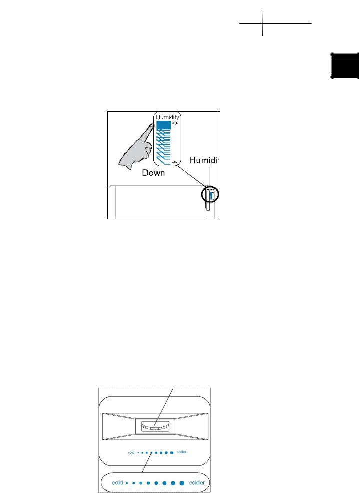
2-4. How to User the Crisper
The appliance is equipped with a crisper for vegetable and fruit storage. You can set the humidity to meet your storage needs.
9 |
1.Turn the humidity regulator (located at the upper right Humidity regulator corner of the crisper) up to get a higher humidity suitable for storage of cucumber, grape, kiwifruit and persimmon etc.
2.Turn the humidity regulator (located at the upper right corner of the crisper) down to get a lower humidity suitable for storage of strawberry, orange, bean, garlic, watermelon, plum and tomato etc.
2-5. How to Use the Delicatessen Drawer
The appliance is equipped with a delicatessen drawer with a temperature range
from-2°C~+3°C.The temperature can be adjusted by the air control knob to meet your storage needs.
1.Turn the air control knob left (weak) to reduce the cooled air moving in the delicatessen drawer and maintain a higher temperature;
2.Turn the air control knob right (strong) to increase the cooled air moving in the delicatessen drawer and maintain a lower temperature.
|
SERVICE MANUAL |
|
|
|
|
Issue 2010-07-05 |
|||
|
Model: HB21FC45N* |
|
Rev. Ref1007S019V0 |
|
|
|
|||
|
|
|
|
|
Chapter3 Disassembly
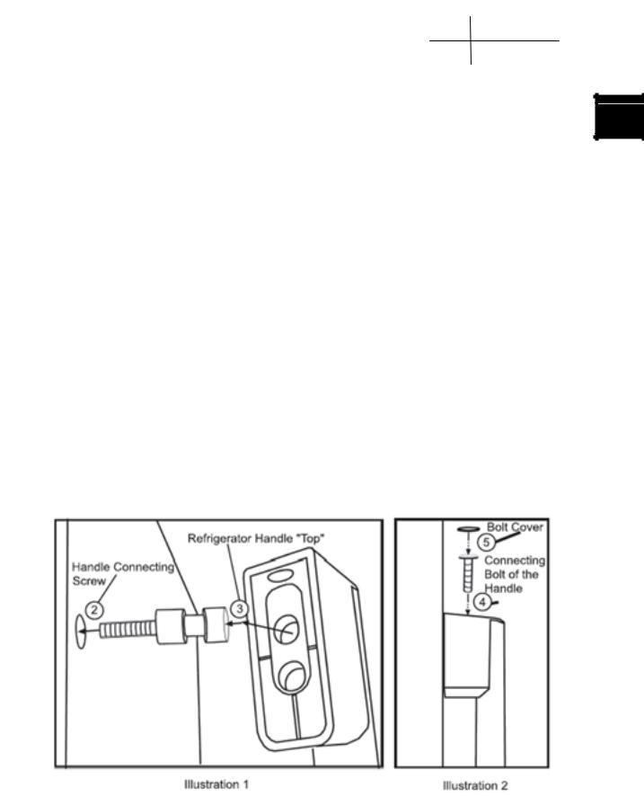
3-1. Door handle installation
10 |
3-1-1.Refrigeration door handle
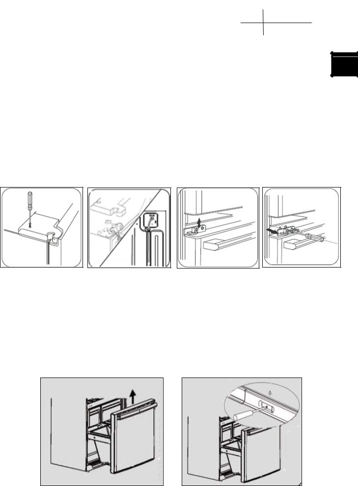
1.Retrieve the handle clearly marked for the Refrigerator Door that needs attachment.
2.Insert the Handle Connecting Screws into the holes provided on the Refrigeration Door. Using a hand held screwdriver tighten the Handle Connecting Screw until the screw threads disappear and the first flat surface of the Handle Connecting Screw touches the Refrigerator Door surface (as shown in illustration1step2). Do not over tighten-damage to the door can occur.
3.Place the Refrigeration Door Handle onto the Handle Connecting Screws using the upper hole of the “Top” Refrigeration Door Handle (as shown in illustration 1-step3); The Refrigeration Door Handle should rest comfortably to the door on these Connecting Screws.
4.Insert the Connecting Bolt into the hole at the top of the Refrigerator Door Handle. Using the provided Hex Driver and tighten until the handle is fixed firmly to the door. Repeat this process for the “Bottom” of the Refrigeration Door Handle (as shown in illustration 2-step4).Be careful when tightening not to scratch the door surface.
5.Place Bolt Covers into the holes on the handle at the top and bottom and push into place (as shown in illustration2step5).
6.To disassemble the Refrigeration Door Handle, follow these directions in reverse.
|
SERVICE MANUAL |
|
|
|
|
Issue 2010-07-05 |
|||
|
Model: HB21FC45N* |
|
Rev. Ref1007S019V0 |
|
|
|
|||
|
|
|
|
|
3-1-2.Freezer door handle
1. Retrieve the handle clearly marked for the Freezer Door that needs attachment.
2.Insert the Handle Connecting Screws into the holes provided on the Freezer Door. Using a hand held screwdriver tighten the Handle Connecting Screw until the screw threads disappear and the first flat surface of the Handle Connecting Screw touches the Freezer Drawer surface (as shown in illustration1step2). Do not over tighten-damage to the door can occur.
3.Place the Freezer Drawer Handle onto the Handle Connecting Screws (as shown in illustration1 –step3).The Freezer Drawer Handle should rest comfortably on these Connecting Screws.
4.Insert the Connecting Bolt into the holes on the bottom of the Freezer Drawer Handle marked “Left”. Using the provided Hex Driver and tighten until the handle is fixed firmly to the door. Repeat this process for the “Right” side of the Freezer Drawer Handle (as shown in illustration 2-step4).Be careful when tightening not to scratch the door surface.
5.To disassemble the Refrigeration Door Handle, follow these directions in reverse.
11 |
|
SERVICE MANUAL |
|
|
|
|
Issue 2010-07-05 |
|||
|
Model: HB21FC45N* |
|
Rev. Ref1007S019V0 |
|
|
|
|||
|
|
|
|
|
3-2 Installing and Removing Door
 Precautions During Dismantling and Installation of The Door
12 |
You may not need to remove the doors! But if you have trouble getting the unit into its final lacation,please follow the below door removal and installation instructions. It is suggected, for your safety, to have two or more people to assist you in completing the below task to avoid bodily injury, product damage,or properly loss.
3-2-1. Right French Door Removal and Installation
1.Remove the screws on the top hinge cover
2.Using a screwdriver,remove the top hinge screws.Remove the hinge, then take the refrigerator door off and place it aside for the time being.
3.Remove the middle hinge,if needed.
4.Install the refrigerant door in reverse sequence,
 When lifting up the refrigerator hinge and separating it from the door body,please be careful not to
drop the door slanted forward.
|
SERVICE MANUAL |
|
|
|
|
Issue 2010-07-05 |
|||
|
Model: HB21FC45N* |
|
Rev. Ref1007S019V0 |
|
|
|
|||
|
|
|
|
|
3-2-2. Left French door removal and installation
1. First remove the top hinge cover as above.
2.Disconnect the water line from back of unit
3.Remove the hinge screws using a screwdriver, and take off the hinge, then remove the door body and place it in a safe position. Disconnect the wire cable connector, ground wire and pull water line out from cabinet.
4.Please remove the middle hinge, if needed.
5.Install the door in the reverse order.
 When lifting the hinge as it separates from the door, be careful it does not lean forward and fall,
causing you bodily harm or damaging the door.
13 |
3-3.Removing and installing Lower Freezer Drawer (If required)
1.First open the drawer as far as possible, and then remove the screw on each side of the drawer.
2.Then pull the drawer body up and towards you, and put it aside in a safe place.
3.Install the drawer in the reverse order.
 Keep children and pets from playing inside the lower drawer as a hiding place. Use caution after drawers and removed, due to the possibility of the plastic track protruding from unit
|
SERVICE MANUAL |
|
|
|
|
Issue 2010-07-05 |
|||
|
Model: HB21FC45N* |
|
Rev. Ref1007S019V0 |
|
|
|
|||
|
|
|
|
|
3-4 Water line installation
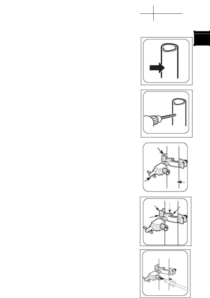
Installation of connecting valves and plumbing must follow all local plumbing guidelines, laws and restrictions.
Install the shutoff valve on a cold water supply line that is frequently used
1.Turn off the main water supplying pipe routine
Turn on the nearest tap till the water pipe is cleaned completely
2.Choose the position of the valve
Choose a position for the valve that is easy to be approached. It is recommended that the valve is connected to the side of a vertical water pipe, and if it is really needed to connect the valve to a level water pipe .Connect it to the upside of the water pipe not the downside, in case the sediment may flow out from the water pipe.
3.The hole of the drill valve
Drill a hole of 1/4inches on the water pipe using a sharp
drill (even using an automatic valve). Clean the burr left on the water pipe by the drill.
Use care not to allow water to flow into the drill
4.Tighten the shutoff valve
5.Tighten the pipe tip
Tighten the bolts of the pipe tip till the closing begins to expand. Don’t let the bolts lf the pipe tip be too tight, otherwise the water pipe is pressed flat.
6.The deposing line of the pipe
The deposing line between the cold water pipe and the refrigerator Drill a hole on the wall or on the floor that is near the wall to a great degree, and let the pipe line go through the hole
Assure the pipe has an enough margin area (about 8 inches [2.4 meters] and make it be three circles with the diameter of each circle about
10 inches [25centimeters].and after this installment is done, the refrigerator can be moved away from the wall.
7.Connect the pipe to the valve
Put the Tightened nuts and the copper shaft on the end side of the pipe and connect the pipe to the stopping valve. Make
sure that the pipe is cut into valve completely. Tighten and press the nut.
14 |
 Loading...