

Page 1

Preface
In this user manual we try to describe the matters concerning the
operation of this GS Series Spindle Servo Drive Unit to the greatest extent.
However, it is impossible to give particular descriptions for all unnecessary
or unallowable operations due to length limitation and products application
conditions; Therefore, the items not presented herein should be regarded as
“impossible” or “unallowable”.
Copyright is reserved to GSK CNC Equipment Co., Ltd. It is
illegal for any organization or individual to publish or reprint this manual.
GSK CNC Equipment Co., Ltd. reserves the right to ascertain their legal
liability.
I
Page 2
GS Series Spindle Servo Drive Unit User Manual
Preface
Dear customers,
We are honored and thankful for your purchase of this GSK product!
This manual describes items concerning GS Series Spindle Servo
Drive Unit in detail, such as performance, installation, connection,
commissioning, usage and maintenance etc.
To ensure safe and effective running, please read this manual carefully
before installation and operation.
To avoid injury to operators and other personnels, and damage to the
mechanical equipments, please pay special attention to the following
warning signs when reading this manual.
Danger Mal-operation may lead to serious injury or death.
Caution Mal-operation may lead to minor injury or physical
damage.
Notice It indicates a potential situation which, if not avoided, may result
in an undesirable result or state.
It reminds users of the important instructions and requirements.
II
Forbidden (definitely cannot be done)
Compulsive (must be done)
Page 3
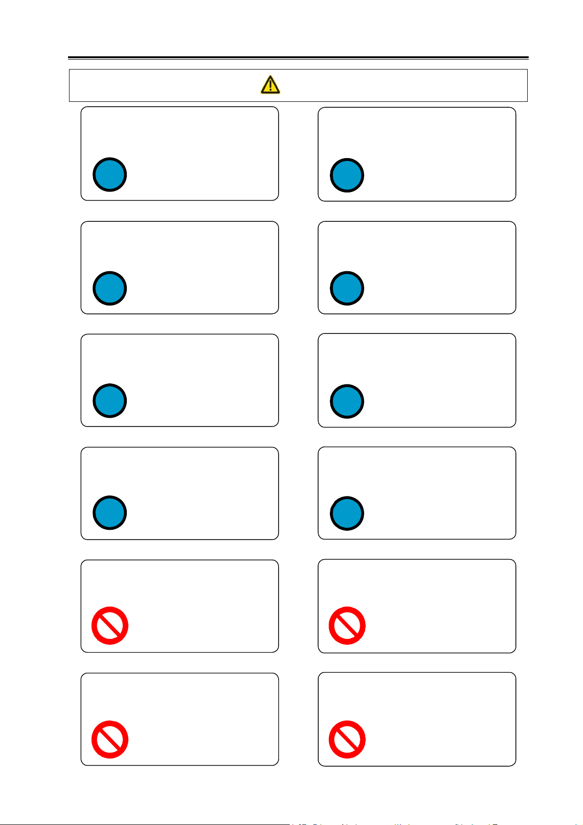
Caution
Tighten all terminals of main circuits
properly.
Failure to observe it may
result in loose connection
!
Make sure that the input power is OFF
before wiring.
!
Wire layout or overhaul should be
done by electrical engineering
technician.
which can easily lead to spark
hazard or even fire disaster.
Failure to observe it may
result in electric shock.
Danger
Mount the drive unit on
noncombustible, and keep it far away
from inflammables.
Moving, checking, and maintaining
equipments or wiring should be
performed 5 minutes after power-off.
Failure to observe it may
!
Make sure the grounding terminal
PE of servo unit is well grounded.
!
result in fire disaster.
Failure to observe it may
result in electric shock.
Failure to observe it may
!
Wiring should be performed according
to the method described in User
Manual.
!
DO NOT operate the switch with
wet hand.
result in electric shock or fire
disaster.
Failure to observe it may
result in equipment damage
and electric shock.
Failure to observe it may
result in electric shock.
Failure to observe it may
!
DO tighten the power terminals and
motor output terminals.
!
DO NOT put hand into servo unit.
result in electric shock.
。
Failure to observe it may
result in fire disaster.
Failure to observe it may
result in electric shock.
DO NOT open the terminal strip cover
after power-on or in running state.
Failure to observe it may
result in electric shock.
DO NOT touch the wiring terminals of
servo unit main circuits.
Failure to observe it may
result in electric shock.
III
Page 4
GS Series Spindle Servo Drive Unit User Manual
The servo unit may be activated suddenly
after power resumption, so DO NOT
operate the servo motor axes connection
device immediately.
Failure to observe it may
result in personal injury.
DO NOT place cables beside sharp
edges, and AVOID heavy load or tension
imposing on cables.
Failure to observe it may
result in electric shock,
equipment fault or damage.
Danger
DO NOT prevent radiation or put
objects in cooling fan or radiator.
Failure to observe it may
result in equipment damage or
fire disaster.
DO NOT perform live-wire operation on
the servo drive device when the cover
of terminal strip is taken apart.
Failure to observe it may
result in electric shock.
Caution
IV
Page 5
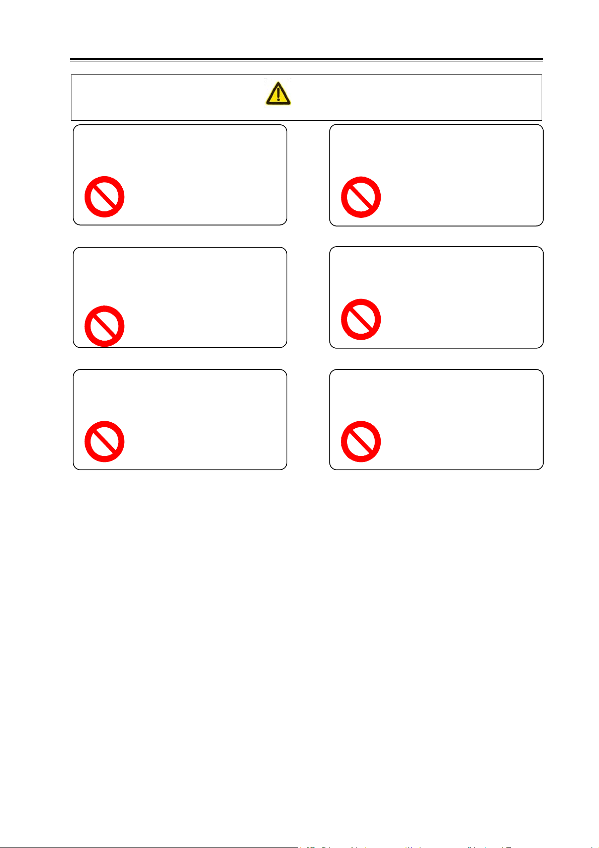
Caution
DO NOT connect power input wires R, S,
T to motor output wire terminals U, V, W.
Failure to observe it may
result in device damage.
DO NOT touch the radiation device of
motor and servo unit when they are
running, because high temperature may
be caused.
Failure to observe it may
result in scald.
DO NOT alter, dismantle or repair the
drive unit without authorization.
Caution
DO NOT turn ON/OFF the input power
frequently.
Failure to observe it may
result in device damage.
DO NOT make excessive changes to
parameters.
Failure to observe it may
result in device damage.
The scrapped components of servo unit
should be handled as industrial waste
and cannot be reused.
Failure to observe it may
result in device damage.
Failure to observe it may
result in accident.
V
Page 6

GS Series Spindle Servo Drive Unit User Manual
Safety Responsibility
Manufacturer’s Responsibility
——Be responsible for the danger which should be eliminated and/or controlled on
design and configuration of the provided Servo Drive Unit and accessories.
——Be responsible for the safety of the provided Servo Drive Unit and accessories.
——Be responsible for the provided information and advice for the users.
User’s Responsibility
——Be trained with the safety operation of Servo Drive Unit and familiar with the safety
operation procedures.
——Be responsible for the dangers caused by adding, changing or altering to the
original Servo Drive Unit and the accessories.
——Be responsible for the failure to observe the provisions for operation, adjustment,
maintenance, installation and storage in the manual.
This manual is reserved by end user.
We are full of heartfelt gratitude to you for supporting us in the
use of GSK’s products.
VI
Page 7

Contents
Contents
CHAPTER I INSTRUCTION ...................................................................................................................... 1
1.1 Basics .............................................................................................................................................. 1
1.2 Product Confirmation ....................................................................................................................... 6
1.2.1 Instruction of AC Spindle Servo Motor Model ........................................................................... 6
1.2.2 Instruction of Spindle Servo Unit .............................................................................................. 7
1.2.3 Overall Appearance of Spindle Servo Unit ............................................................................... 8
1.3 Technical Specification .................................................................................................................. 11
1.3.1 Technical Specification of Spindle Motor ................................................................................ 11
1.3.2 Technical Specification of AC Spindle Servo Unit .................................................................. 13
1.4 Ordering Guidelines ....................................................................................................................... 15
1.4.1 Model Selection Process ........................................................................................................ 15
1.4.2 Examples ................................................................................................................................ 15
1.4.3 Standard Ex-factory Accessories ............................................................................................ 17
CHAPTER II INSTALLATION/MOUNTING ............................................................................................. 21
2.1 Spindle Servo Motor ...................................................................................................................... 21
2.1.1 Dimensions for Spindle Motor Installation .............................................................................. 21
2.1.2 Installation of Spindle Motor ................................................................................................... 23
2.2 Spindle Servo Unit ......................................................................................................................... 25
2.2.1 Installation Dimension ............................................................................................................. 26
2.2.2 Installation Intervals ................................................................................................................ 28
CHAPTER III CONNECTION .................................................................................................................. 31
3.1 Connection of Peripheral Equipments ........................................................................................... 32
3.2 Connection of Main Circuit ............................................................................................................ 37
3.2.1 Connection .............................................................................................................................. 37
3.2.2 Wiring of Main Circuit .............................................................................................................. 38
3.2.3 Servo Motor Connection Instruction ....................................................................................... 38
3.3 Connection of Control Signal ......................................................................................................... 40
3.3.1 CN1 Control Signal ................................................................................................................. 40
3.3.2 Speed Command Input ........................................................................................................... 43
3.3.3 Position Command Input ........................................................................................................ 44
3.3.4 Digital Input ............................................................................................................................. 47
3.3.5 Digital Output .......................................................................................................................... 49
3.3.6 Position Signal Output ............................................................................................................ 52
3.4 Connection of Position Feedback Signal ....................................................................................... 53
3.4.1 Motor Encoder Position Feedback Signal Interface CN2 ....................................................... 53
VII
Page 8

GS Series Spindle Servo Drive Unit User Manual
3.4.2 2nd Position Feedback Signal Interface CN3 ........................................................................ 57
3.4.3 Interface CN3 of GS Series MDR Products ........................................................................... 58
3.5 GSK-CAN Communication ............................................................................................................ 59
3.6 Connection in Different Working Mode ......................................................................................... 60
3.6.1 Connection in Speed Mode .................................................................................................... 60
3.6.2 Connection in Position Mode ................................................................................................. 63
3.6.3 Connection in Speed/Position Mode ...................................................................................... 65
CHAPTER IV DISPLAY AND OPERATION ........................................................................................... 69
4.1 Operation Panel ............................................................................................................................ 69
4.2 Display Menu ................................................................................................................................ 70
4.3 Status Monitoring .......................................................................................................................... 71
4.4 Parameter Setting ......................................................................................................................... 74
4.5 Parameter Management ............................................................................................................... 75
CHAPTER V GENERAL COMMISSIONING .......................................................................................... 77
5.1 Running in Manual/JOG Mode...................................................................................................... 78
5.1.1 Manual Running ..................................................................................................................... 79
5.1.2 JOG Running.......................................................................................................................... 80
5.2 Running in Speed Mode ............................................................................................................... 81
5.2.1 Analog Speed Command ....................................................................................................... 81
5.2.2 Internal Speed Command ...................................................................................................... 84
5.3 Running in Position Mode ............................................................................................................. 85
5.4 Running in Speed/Position Mode ................................................................................................. 87
CHAPTER VI FUNCTIONALITY TESTING ............................................................................................ 91
6.1 Instruction for Basic Performance Parameters Setting ................................................................. 91
6.1.1 Setting Methods ..................................................................................................................... 91
6.1.2 Three Gains of Closed-Loop Control ..................................................................................... 93
6.2 Switching of Motor Rotation Directions ......................................................................................... 94
6.3 Braking Stop.................................................................................................................................. 96
6.4 Testing in Position Mode ............................................................................................................... 97
6.4.1 Electronic Gear Ratio of Position Command ......................................................................... 97
6.4.2 Position Arrival Signal ............................................................................................................ 98
6.4.3 Position Deviation Clear ......................................................................................................... 99
6.4.4 Pulse Command Inhibition ..................................................................................................... 99
6.5 Testing in Speed Mode ............................................................................................................... 100
6.5.1 Orientation Function ............................................................................................................. 100
6.5.2 Adjustment of Analog Commands ....................................................................................... 105
6.5.3 Speed Arrival Signal ............................................................................................................. 106
VIII
Page 9

Contents
6.5.4 Zero Speed Clamp ................................................................................................................ 107
6.5.5 Speed Command Electronic Gear Ratio .............................................................................. 108
6.6 Spindle Clamp Interlock Signal (BREF)....................................................................................... 109
CHAPTER VII PARAMETERS .............................................................................................................. 111
7.1 Parameter List ............................................................................................................................. 111
CHAPTER VIII ABNORMALITIES AND REMEDIES ............................................................................ 123
8.1 Remedies for Normal Faults ........................................................................................................ 123
8.1.1 Speed Mode ............................................................................................................................. 123
8.1.2 Position Mode ....................................................................................................................... 125
8.1.3 Others ................................................................................................................................... 126
8.2 Alarms and Remedies ................................................................................................................. 128
8.3 Inspection and Maintenance ........................................................................................................ 133
APPENDIX A Model Code Parameters and Feed Servo Motors Table ................................................ 135
APPENDIX B Peripheral Equipments ................................................................................................... 136
B.1 Circuit Breaker and Contactor (essential) ................................................................................... 136
B.2 Three-phase AC filter (recommended)........................................................................................ 136
B.3 AC Reactor (recommended) ....................................................................................................... 137
APPENDIX C BRAKING RESISTOR SELECTION............................................................................... 138
APPENDIX D CONNECTION DIAGRAMS BETWEEN SPINDLE SERVO UNIT AND CNC SYSTEM
............................................................................................................................................................... 141
IX
Page 10

Page 11
Chapter I Instruction
CHAPTER I INSTRUCTION
1.1 Basics
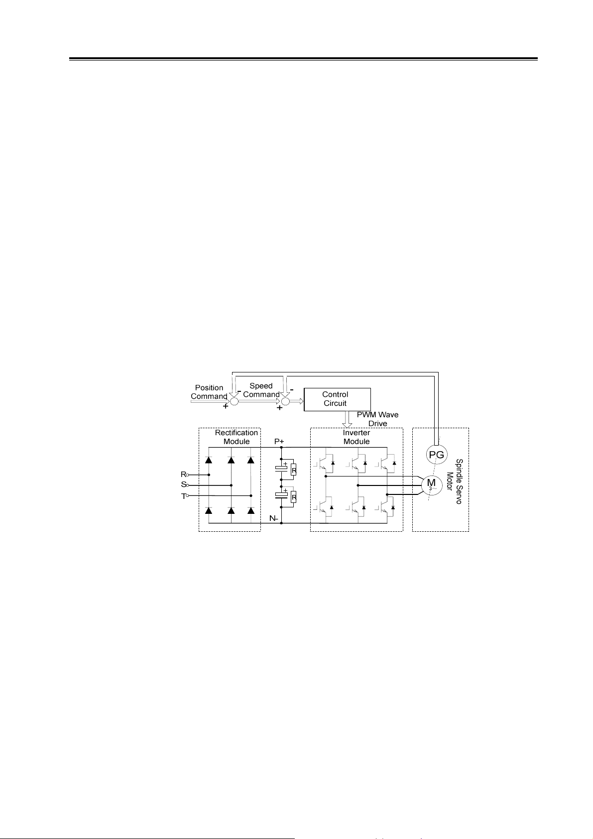
¾ Fundamental principles and circuits of spindle servo drive
The spindle servo drive is composed of spindle servo unit and spindle servo motor (three-phase
AC asynchronous servo motor, hereinafter called servo motor). The servo unit rectifies AC to DC, and
by controlling the ON/OFF of power transistor, it generates current approximated to sinewave whose
phase difference is 120° in the three-phase stator winding of servo motor (i.e., DC-AC). Thus, a
magnetic field is created in the servo motor, and the rotator generates current as a result of magnetic
field induction. The interaction between the inductive current and magnetic field leads to the
generation of a torque which causes the rotator to work. Higher frequency of current which goes
through the servo motor winding corresponds to quicker servo motor speed; the larger current
amplitude corresponds to larger output torque of the servo motor (torque= force × arm length). Figure
1-1 shows the main circuit of servo unit; PG represents the encoder.
Fig. 1-1 Main circuit of spindle servo unit
¾ Basic structure of spindle servo drive
The servo unit receives speed (or position) commands from control device (also called upper
computer) such as CNC system. It controls the frequency and magnitude of current which goes
through the servo motor winding, so that the rotation speed (or angle) of servo motor rotator can be
approximated to the speed (or position) command value, and the difference between actual rotation
speed (or angle) and commanded value can be detected. By constantly adjusting the frequency and
magnitude of current, the servo unit can limit the differences within the required range. Figure 1-2
shows the basic structure of spindle servo drive.
1
Page 12
GS Series Spindle Servo Drive Unit User Manual
Specify
CNC
System
¾ General concept of control
z
Control: A process of the characteristics (such as speed) of an object (such as servo motor)
reaching or approximating to the desired value is called CONTROL. The object herein is called
PLANT; and its characteristic is called CONTROLLED VARIABLES; the unit which realizes the
control is called CONTROL UNIT; the process of receiving the desired value by the control unit is
+
-
Spindle Servo Drive
Control
Unit
Fig. 1-2 Basic structure of spindle servo drive
Power Drive
Unit
Feedback
Detection
Motor Machine
called SPECIFY; the process of inputting and reacting to controlled variable is called FEEDBACK; the
unit that detects the controlled variables is called FEEDBACK UNIT; the feedback can be divided into
positive feedback (same direction) and negative feedback( reversed direction) according to the
controlled variables and output direction. The drive is composed of plant, feedback unit and control
unit. There are two kinds of drives: open-loop control device and closed-loop control device. They are
distinguished by the absence/presence of feedback unit and its position in drive. The closed-loop
control device described in this manual is negative feedback closed-loop control device.
In this manual, the spindle servo unit is the control unit; the plant is the servo motor; the motor
rotation speed (or angle) is the controlled variable; the encoder is the feedback unit; the speed
feedback is realized when actual speed is detected by encoder for speed control. Spindle servo unit
belongs to closed-loop control device.
z Open-loop control device: Feedback unit is absent in the control device, so the actual
controlled variables do not affect the output of control unit. Take stepper motor drive for example:
after the servo unit outputs the phase sequence changes of current, the rotator of stepper motor
should follow the change; however, since there is no feedback unit, the rotator may not catch up with
the changes due to overload or fast acceleration/deceleration, this is the so-called
“out-of-synchronism”. Shown in Figure 1-3.
Machine
Specify
Command
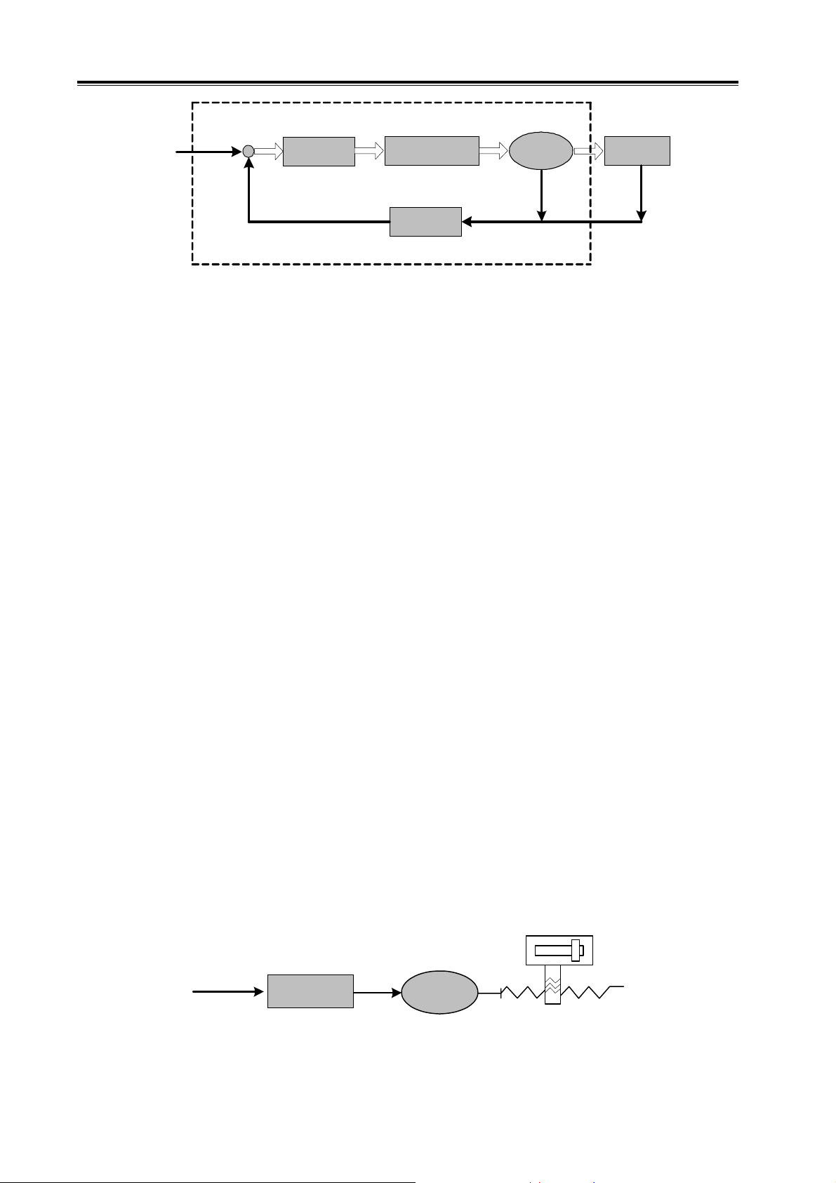
z Closed-loop control: The controlled variable is detected by feedback unit and sent to
2
Drive
Circuit
Fig. 1-3 Open-loop control device
Motor
Page 13
Chapter I Instruction
control unit. According to the detection points, the closed-loop control device can be divided into
full-closed-loop control and semi-closed-loop control. The former one is to detect the controlled
variables directly for feedback (see Fig. 1-4); the mechanical position is controlled variables; the
grating ruler mounted on the machine is taken as feedback unit; the encoder on the servo motor
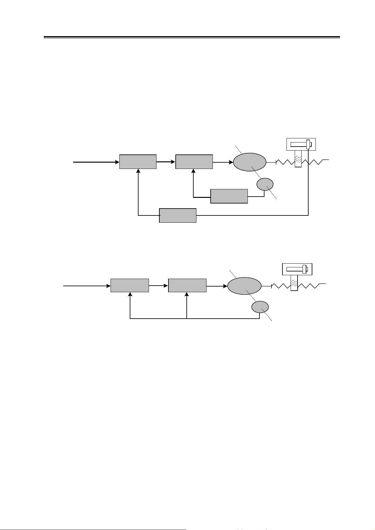
serves as speed feedback unit. Thus the full-closed-loop control can be realized. If there is no grating
ruler, the encoder serves as both position and speed feedback unit (see Fig. 1-5). Thus, the
semi-closed-loop control can be realized.
Machine
Specify
Command
Specify
Command
+
+
Position
Comparision
Position
Comparision
+
Speed
Comparision
--
Speed
Feedback
Position
Feedback
Fig. 1-4 Full-closed-loop control device
+
Speed
Comparision
--
Fig. 1-5 Semi-closed-loop control device
Motor
PG
Machine
Motor
PG
z PID control: It is the most commonly used algorithm. “P” is Proportional, representing the
linear proportional relationship between input and output of control unit. The larger the value is, the
more sensitive the system is, and the smaller the steady-state error will be (impossible to eliminate);
however, too large proportional coefficient will lead to system instability. “I” is Integral, representing
the accumulation of past errors. Larger integral time constant means the system is more stable till the
stead-state error is eliminated; however, it also may lead to lower response of the system. “D” is
Differential, representing the prediction of future errors, based on current rate of change. It can
decrease the following error and improve the dynamic property. When the integral is too large, the
system will be unstable. P, I, D are interacted for the balance among system response, control
precision and stability. Since the integral control will easily cause impact and oscillation, PI control
(i.e., proportion and integral control) is mainly described in this manual.
¾ Concept about servo control
There are three kinds of control mode: position control, speed control and torque control. Shown
3
Page 14
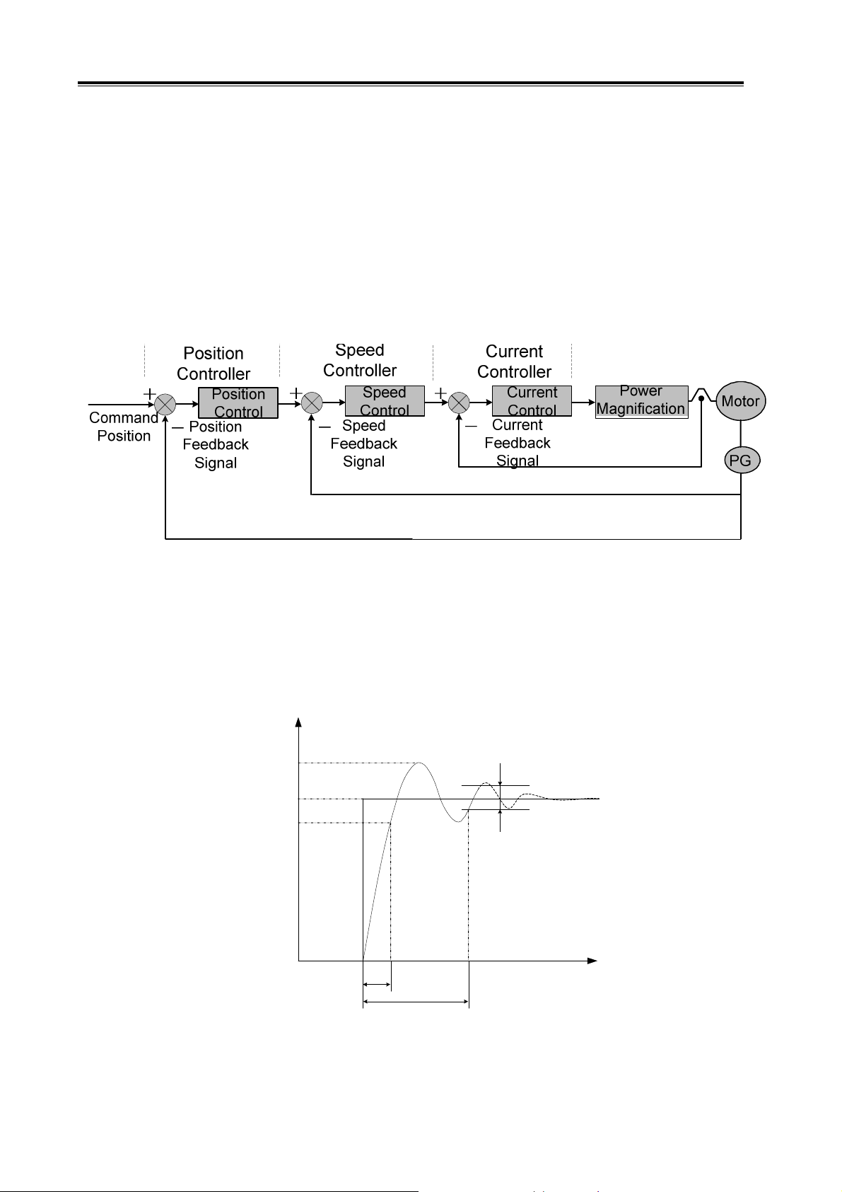
GS Series Spindle Servo Drive Unit User Manual
in Fig. 1-6:
z
Position control: Specify the rotation direction and angle (position) of the motor in forms of
digital pulse or data communication.
z Speed control: Specify the rotation direction and speed of the motor in forms of analog
voltage or data communication.
z Torque control: Specify the magnitude and direction of output torque of the motor in forms of
analog voltage or data communication.
The servo drive described in this manual repels the torque control signal, therefore the torque
control mode is not provided here.
Fig. 1-6 Three-loop control system
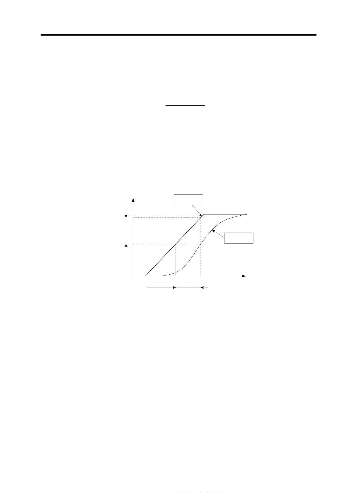
¾ Performance norm of spindle servo drive
Dynamic performance:
spindle servo drive when the load is specified or changed. The following figure shows the dynamic
response of step signal specified by spindle servo drive (the full line represents the specified signal
and dashed line represents the output signal; similarly hereinafter).
means the response speed, dynamic error and steady-state error of
C(t)
Rmax(t)
R(t)
0.9R(t)
±5%R(t)
t r
s
t
Fig. 1-7 Dynamic response curve
Rise time tr: The duration that the rotation output value rises from 0 to 90% of the steady-state
value for the first time. It represents the speed of dynamic response.
4
t
Page 15
Chapter I Instruction
Settling time ts: The range -5%~+5% of the steady-state value is taken as permitted error zone.
The settling time is the minimum duration of the response curve to reach the zone (no excess any
more). It is used to measure the speed of the whole control process.
Percent overshoot σ: It is the maximum fraction by which the response overshoots the
steady-state value and expressed as a percentage, i.e.
)()(
−
σ
(%)
max
=
tRtR
×
)(
tR
%100
Steady-state error
: The difference between the steady-state output value to the reference input
value at steady state is called the steady state error of the system.
Static performance: Stability is the crucial factor of a spindle servo drive. The static
performance mainly refers to positioning accuracy which means the difference between the reference
state and actual state after the transient process. The static precision can be affected by
measurement device error as well as the system error which is related to the system structure and
parameters. Fig. 1-8 shows the static curve of position servo drive.
θ
Error
Following
Lag
Commanded
Position
Following
Response
t
Fig. 1-8 Static curve
Following error: The difference between the required position and actual position is called
following error. It equals to commanded position value minus actual position value.
Servo rigidity: The capacity of resisting deviation which is caused by load.
¾ Comparison between spindle servo drive and inverter drive
Although both two kinds of devices can realize the conversion of AC-DC-AC, and drive the
three-phase asynchronous motor, the spindle servo drive bears larger current frequency range and
wider valid regulating range. Since an encoder is mounted on servo motor, the spindle servo drive
belongs to closed-loop control device. Whereas, no encoder is mounted on an inverter-fed motor, the
inverter drive belongs to open-loop control device. Motor’s rotation speed will change as the load
changes; however, since feedback control function is not available, the inverter cannot recover the
speed like the servo unit does. To reduce cost, the overload capacity of inverter is 10%~20%, and
that of servo unit is greater than 50%. Higher overload capacity means faster acceleration and
response.
Compared with inverter drives, the spindle servo drives have the following advantages:
5
Page 16
GS Series Spindle Servo Drive Unit User Manual
z Both speed and position control are available; the control precision is high;
z Wider regulating range; capable of outputting valid torque in zero-speed state;
z Small speed fluctuation when load changes; quick to recover;
z Strong overload capacity; fast response; high efficiency; adaptable to sudden start/stop
conditions;
1.2 Product Confirmation
Check the following items after receiving the products. Please contact us or the supplier if you
come across any question.
Item Remark
Check the consistency of servo
unit and servo motor
Check the completeness of
accessories
Check whether the product is
damaged during delivery
Check whether the screw is
loose
Check the contents on packing list and contact
the supplier if an inconsistency is found.
Check for loose connection with a screwdriver.
Check the nameplate.
Check the overall appearance.
Caution
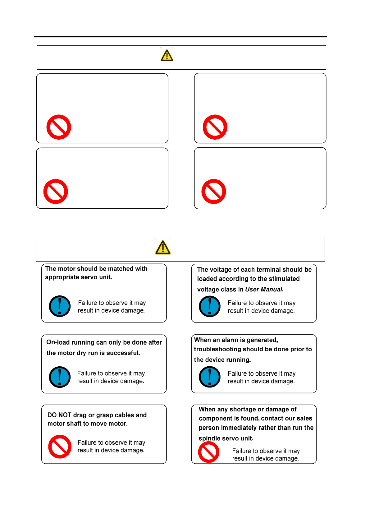
1. Spindle servo unit with loss or damage of parts should not be installed.
2. Servo unit should be matched with a servo motor with suitable power.
3. There are two types of GS series products: D-SUB and MDR. Make sure that the
used product meets the requirements.
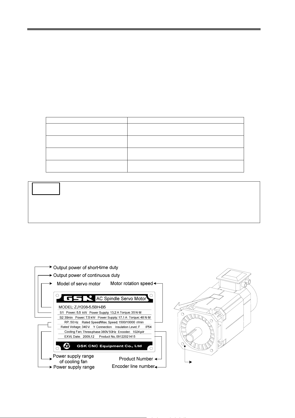
1.2.1 Instruction of AC Spindle Servo Motor Model
¾ Nameplate of spindle servo motor:
Flange mounting plane B5
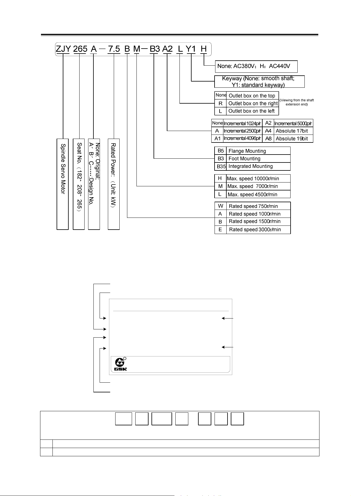
¾ Instruction of spindle servo motor model:
6
Page 17
Chapter I Instruction
1.2.2 Instruction of Spindle Servo Unit
Example: (nameplate)
Corresponding servo motor model
Product model
AC Asynchronous Spindle Servo Unit
Model: SVD:
GS3075Y-CP2-7.5
Servo Motor
Input Power
No.
R
Product number
Input power supply
Model instruction:
ZJY-208-7.5BH
Three-phase 380V(-15%~+10%)50/60Hz
100620
EXW. Date
GSK CNC Equipment Co., Ltd
Tel .020 -83969288 Fax.81997083
V3.04
2010/9
Software version
Ex-factory date
GS 3 075 Y C P
①② ③
GS Series MDR Servo Unit, G: GSK; S: SERVO
①
Voltage grade code, 2: 220V; 3: 380V; 4: 440V.
②
④
-
⑤⑥2⑦
7
Page 18

GS Series Spindle Servo Drive Unit User Manual
Nominal current of power component (in three digits): 048, 050, 075, 100, 148, 150 (unit: A)
③
Motor type: T: synchronous servo motor; Y: asynchronous servo motor.
④
Communication bus code; N: none; C: GSK-CAN; L: GSK-Link
⑤
Feedback (encoder) interface type code; P: incremental encoder; A: Absolute encoder, no backup battery; B:
⑥
absolute encoder (with backup battery which is used when power-off).
Feedback (encoder) interface configuration code (in 1 digit); 1: The input interface CN2 for motor feedback
(i.e., the 1
⑦
feedback.
Position feedback signal interface type and configuration:
st
position feedback); 2: Input interfaces CN2 and CN3 for motor feedback and the 2nd position
⑥ ⑦
1
CN2; incremental encoder;
Instruction for feedback (encoder) interface type and configuration
P
2 CN2 and CN3; incremental encoder;
CN2; incremental encoder or absolute encoder (compatible with Biss and TAMAGAWA
1
A
(B)
communication protocols; automatic identification);
CN2 and CN3; incremental encoder or absolute encoder (compatible with Biss and
2
TAMAGAWA communication protocols; automatic identification);
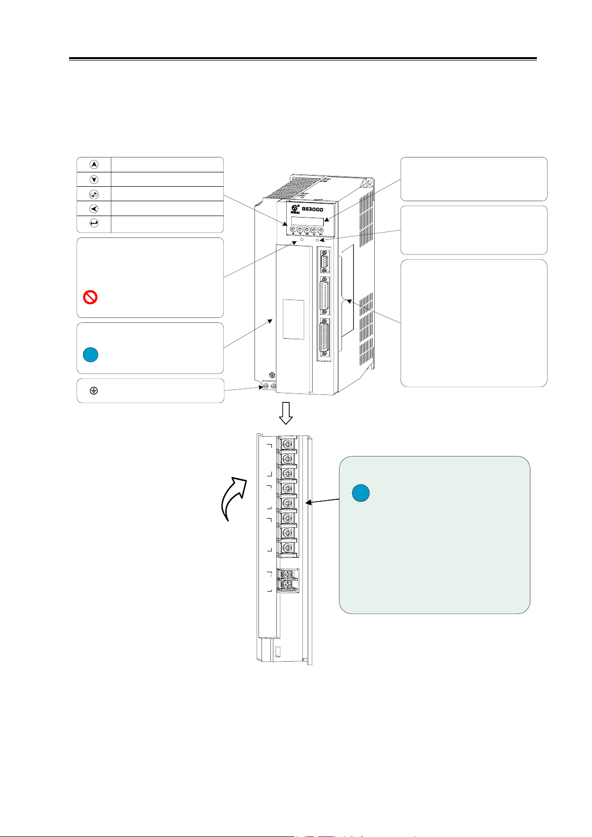
1.2.3 Overall Appearance of Spindle Servo Unit
According to different signal interfaces, the GS Series Spindle Servo Unit can be divided into
D-SUB type and MDR type. The products that adopt D-SUB interfaces provided by WIESON
Company belong to D-SUB type. They are matched with incremental encoder and not equipped with
GSK-CAN. The products that adopt MDR interfaces provided by 3M Company belong to MDR type.
They are compatible with absolute encoder and equipped with GSK-CAN bus.
8
Page 19
Chapter I Instruction
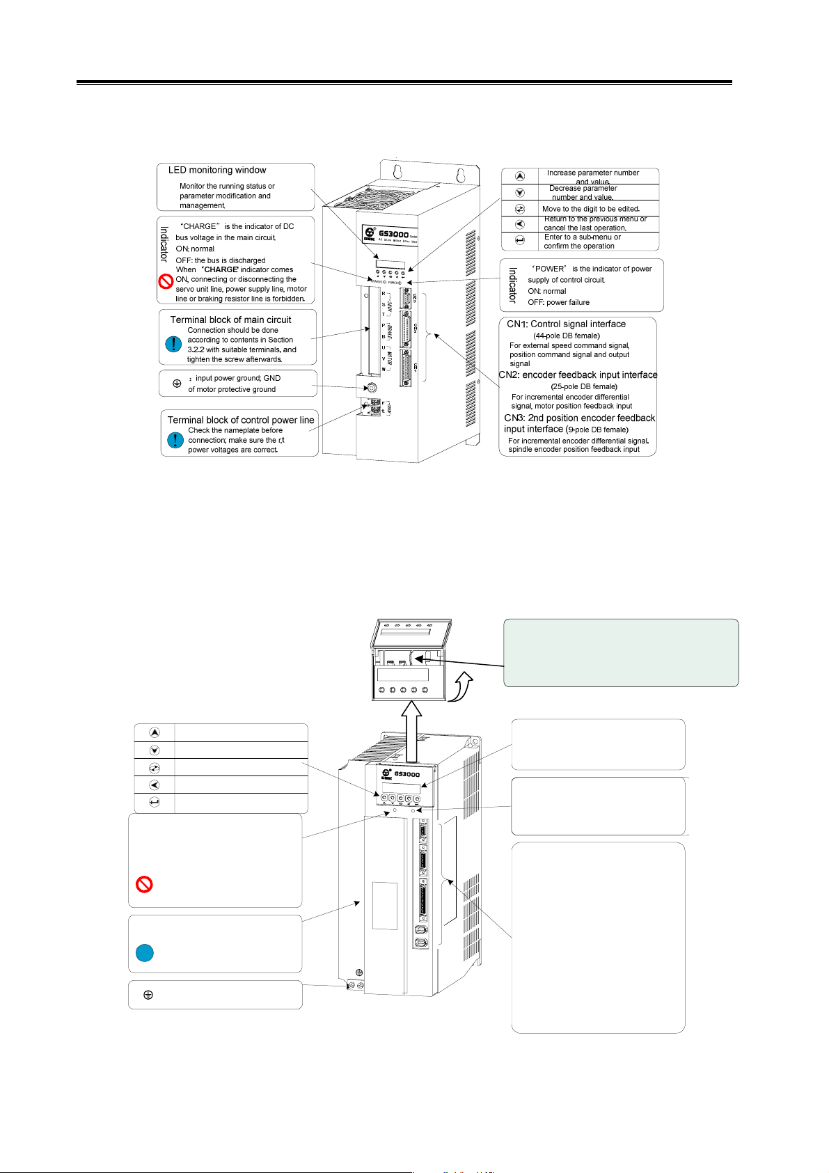
z Overall Appearance of GS Series AC Spindle Servo Unit (D-SUB Type)
The figure below shows the structure of following products: GS3048Y-N Series, GS3050Y-N
Series, GS3075Y-N Series GS3100Y-N Series, GS3148Y-N Series, GS4048Y-N Series, GS4050Y-N
Series, GS4075Y-N Series, GS4100Y-N Series, GS4148Y-N Series.
Increase parameter number
and value.
Decrease parameter
number and value.
Move to the digit to be edited.
Return to the previous menu or
cancel the last operation.
Enter to a sub-menu or
confirm the operation
Indicator
‘CHARGE” is the indicator of DC
bus voltage in the main circuit.
ON: normal
OFF: the bus is discharged
When ‘CHARGE' indicator comes
ON, connecting or disconnecting the
servo unit line, power supply line, motor
line or braking resistor line is forbidden.
Terminal block of main circuit
Connection should be done
according to contents in Section
!
3.2.2 with suitable terminals, and
tighten the screw afterwards.
:input power ground; GND
of motor protective ground
R
S
r
e
i
e
s
C
A
e
S
o
v
r
M
t
o
r
o
D
i
r
e
v
U
n
t
i
C
H
A
G
R
E
P
O
W
E
R
C
N
3
C
N
2
C
N
1
LED monitoring window
Monitor the running status or
parameter modification and
management.
Indicator
‘POWER’ is the indicator of
power supply of control circuit.
ON: normal
OFF: power failure
CN1: Control signal interface
(44-pole DB female)
For external speed command signal,
position command signal and output
signal
CN2: encoder feedback input interface
For incremental encoder differential
signal, motor position feedback input
(25-pole DB female)
CN3: 2nd position encoder feedback
input interface
For incremental encoder differential signal,
spindle encoder position feedback input
(9-pole DB female)
Open
R
~380V
S
T
BRAKE
P
B
U
MOTOR
V
W
r
380V
t
Terminal block of main circuit
Check the nameplate before
!
connection; make sure that the input
power voltages R, S, T, r, t are
correct. Connect to U, V, W as
market at the terminal end; if Err-27
occurs, exchange any of the two
phases.
Fig. 1-9 (a) Overall appearance of GS Series AC spindle servo unit (D-SUB type)
9
Page 20
GS Series Spindle Servo Drive Unit User Manual
The figure below shows the structure of following D-SUB products: GS3150Y-N Series,
GS4150Y-N Series.
Fig. 1-9 (b) Overall appearance of GS Series AC spindle servo unit (D-SUB type)
z Overall Appearance of GS Series AC Spindle Servo Unit (MDR Type)
The figure below shows the structure of following products: GS3048Y-C Series, GS3050Y-C
Series, GS3075Y-C Series, GS3100Y-C Series, GS3148Y-C Series, GS4048Y-C Series,
GS4050Y-C Series, GS4075Y-C Series, GS4100Y-C Series, GS4148Y-C Series.
Backup battery
(See the instruction of servo unit model)
Increase parameter number
and value.
Decrease parameter
number and value.
Move to the digit to be edited.
Return to the previous menu or
cancel the last operation.
Enter to a sub-menu or
confirm the operation
Indicator
‘CHARGE” is the indicator of DC
bus voltage in the main circuit.
ON: normal
OFF: the bus is discharged
When ‘CHARGE' indicator comes
ON, connecting or disconnec ting the
servo unit line, power supply line, motor
line or braking resistor line is forbidden.
Terminal block of main circuit
Connection should be done
according to contents in Section 3.2. 2
with suitable terminals, and tighten
!
the screw afterwards.
:input power ground; GND
of motor protective gr ound
R
S
r
e
s
i
e
A
C
S
e
o
r
v
M
o
o
r
t
D
v
r
i
e
U
n
i
t
C
R
A
H
E
G
P
O
R
E
W
C
N
3
C
N
2
C
N
1
C
N
4
C
N
5
LED monitoring window
Monitor the running sta tus or
parameter modification and
management.
Indicator
‘POWER’ is the indicator of power
supply of control circuit.
ON: normal
OFF: power failure
CN1: control signal interface
(50-pin high-density )
For external speed command signal, posit ion
command signal, input/output signal.
CN2: encoder feedback input
interface (26-pin high-density)
For incremental or absolute encoder
feedback input signal
CN3: 2nd position encoder feedback
input interface (20-pin high-density)
For spindle encoder position feedback
input, incremental or absolute input signal.
CN4, CN5: GSK-CAN
communication interface
Realize servo unit commissioning and
real-time monitoring.
10
Fig. 1-10 (a) Overall appearance of GS Series AC spindle servo unit (MDR type)
Page 21
Chapter I Instruction
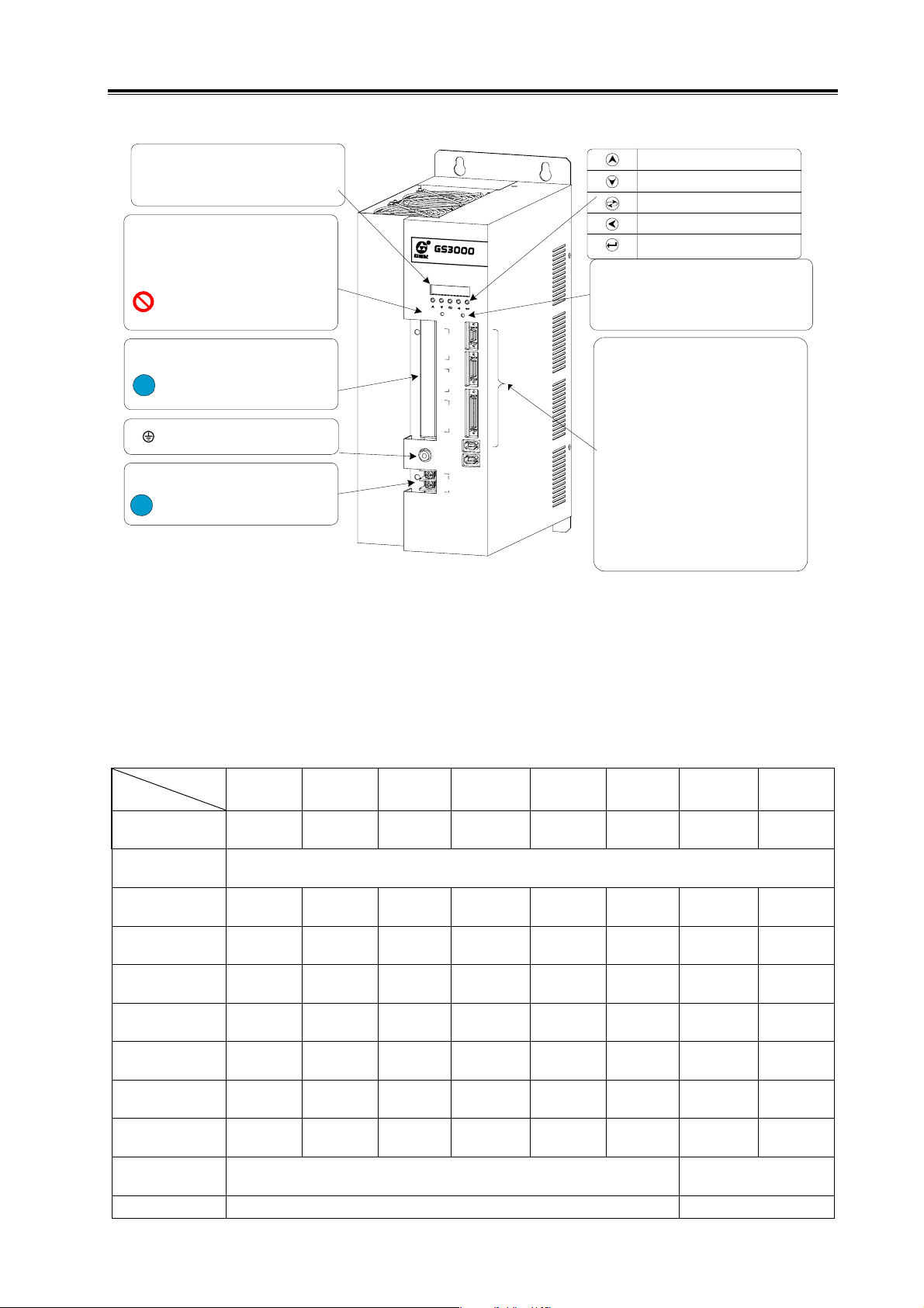
The figure below shows the structure of following products: GS3150Y-C Series, GS4150Y-C Series.
LED monitoring window
Monitor the running status or
parameter modification and
management.
Indicator
‘CHARGE” is the indicator of DC
bus voltage in the main circuit.
ON: normal
OFF: the bus is discharged
When ‘CHARGE' indicator comes
ON, connecting or disconnecting the
servo unit line, power supply line, motor
line or braking resistor line is forbidden.
Terminal block of main circuit
Connection should be done
according to contents in Section 3.2.2
with suitable terminals, and tighten
!
the screw afterwards.
:input power ground; GND
of motor protective ground
Terminal block of control power line
Check the nameplate before
connection; make sure the r,t
!
power voltages are correct.
Fig. 1-10 (b) Overall appearance of GS Series AC spindle servo unit (MDR type)
R
C
A
H
S
e
r
i
e
S
e
r
v
o
P
O
W
~380V
BRAKE
MOTOR
380V
s
M
t
o
o
r
D
r
v
i
e
U
i
n
t
E
R
C
N
3
C
N
2
C
N
1
C
N
4
C
N
5
A
C
R
G
E
R
S
T
P
B
U
V
W
r
t
Increase parameter number
and value.
Decrease parameter
number and value.
Move to the digit to be edited.
Return to the previous menu or
cancel the last operation.
Enter to a sub-menu or
confirm the operation
Indicator
‘POWER’ is the indicator of power
supply of control circuit.
ON: normal
OFF: power failure
CN1: control signal interface (50-
pin high-density )
For external speed command signal, position
command signal, input/output signal.
CN2: encoder feedback input
interface (26-pin high-density)
For incremental or absolute encoder
feedback input signal
CN3: 2nd position encoder feedback
input interface (20-pin high-density)
For spindle encoder position feedback
input, incremental or absolute input signal.
CN4, CN5: GSK-CAN
communication interface
Realize servo unit commissioning and
real-time monitoring.
1.3 Technical Specification
1.3.1 Technical Specification of Spindle Motor
SPEC
Item
Rated power
(kW)
Servo Unit
Power Supply
Rated Current
(A)
Rated
Frequency(Hz)
Rated
Torque(N·m)
30min Power
(kW)
30min Current
(A)
30min Torque
(N·m)
Rated Speed
(r/min)
Constant Power
Range
Max. Speed
ZJY208
-2.2AM
ZJY208
-3.7AM
ZJY208
-5.5AM
ZJY265
-7.5AM
2.2 3.7 5.5 7.5 11 15 1.5 2.2
Three-phase AC 380V 50 Hz /60Hz
6.7 10.2 15.5
21 31 48.3
33.3 33.3 33.3 33.3 33.3 33.3 50 50
21 35 53
72 105 143
3.7 5.5 7.5 11 15 18.5 2.2 3.7
9.8 13.8 19.6
35 53 72
1000
1000
1000
28 39 56
105 143 177
1000 1000 1000
1000~4000
M:7000 H:10000
ZJY265
-11AM
ZJY265
-15AM
ZJY182
-1.5BH
ZJY182
-2.2BH
7.3 7.5
9.5 14
9.3 11
14 24
1500
1500
11
Page 22

GS Series Spindle Servo Drive Unit User Manual
SPEC
Item
Rotary Inertia
Weight (kg)
Installation
Power Supply of
Cooling Fan
SPEC
Item
Rated Power
(kW)
Servo Unit
Power
Supply
Rated
Current (A)
Rated
Frequency
(Hz)
Rated
Torque
(N·m)
30min Power
(kW)
30min
Current (A)
30min
Torque
(N·m)
Rated Speed
(r/min)
Constant
Power
Range
Max. Speed
Rotary
Inertia
Weight (kg)
Installation
Power
Supply of
Cooling Fan
Protection
Level
Insulation
Level
Vibration
Level
Internal
Encoder
ZJY182-3.7BH
Three-phase
ZJY208
-2.2AM
0.0168 0.0238 0.0309 0.0413 0.0826 0.086 0.0056 0.0074
51 66 77 51 125 143 27 32
Three-phase AC 380V 50Hz 40W
3.7 3.7 5.5 7.5 7.5 11 15
15.5
50 50 50 50 50 50 50
24
5.5 5.5 7.5 11 11 15 18.5
19.6
35
1500
H:10000 M:7000, H:10000 M:7000
0.0115 0.0168 0.0238 0.0309 0.0413 0.0744 0.0826
43 51 66 77 89 107 125
IM B35 IM B5 or B3
AC 380V
50Hz 30W
0.08A
ZJY208
-3.7AM
0.14A
ZJY208-3.7B ZJY208-5.5B ZJY208-7.5B ZJY265-7.5BM ZJY265-11BM ZJY265-15B
8.9 13.7 18.4 18 26 35
24 35 48 49 72 98
13 18 25 26 34 42
35 48 70 74 100 123
1500 1500 1500 1500 1500 1500
Three-phase AC 380V 50Hz 40W 0.14A
ZJY208
-5.5AM
IM B5 or B3 IM B35
Three-phase AC 380V 50 Hz /60Hz
ZJY265
-7.5AM
Three-phase AC 380V 50Hz 70W
1500~5000
IP54(GB/T 4942.1—2006)
F (GB 755—2008)
R(GB 10068—2008)
Incremental encoder1024 p/r
ZJY265
-11AM
0.21A
ZJY265
-15AM
Three-phase AC 380V 50Hz
ZJY182
-1.5BH
Three-phase AC 380V
50Hz 30W 0.08A
70W 0.21A
ZJY182
-2.2BH
M
12
Page 23
Chapter I Instruction
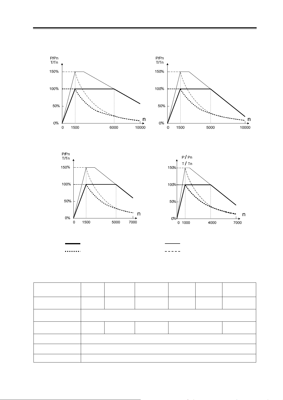
Mechanical Characteristics of Motor
P/P
: Power/Rated power; T/TN: Torque/Rated torque; n: Rotation speed of spindle servo motor;
N
ZJY182 rated rotation speed: 1500r/min ZJY208 rated rotation speed: 1500r/min
ZJY265 rated rotation speed: 1500r/min ZJY208, ZJY265 rated rotation speed: 1500r/min
Power in continuous working status; Power in 30min’s working status;
Torque in continuous working status; Torque in 30min’s working status
1.3.2 Technical Specification of AC Spindle Servo Unit
Model
Rated Power (kW)
Input Power
Dimension (mm)
(width×height×depth)
Regulating Range
(r/min)
Speed Fluctuation
Rate
Working Mode
GS3048Y
GS4048Y
1.5, 2.2 3.7, 5.5 5.5, 7.5 7.5, 11 11 15, 18.5
Input power of GS3□□□Y Series is: Three-phase AC380V(0.85~1.1), 50/60Hz±1Hz
Input power of GS4□□□Y Series is: Three-phase AC440V(0.85%~1.1), 50/60Hz±1Hz
112×230×1
82
GS3050Y
GS4050Y
120×270×218 130×305×248.5 160×305×273.5 160×370×273.5
MANUAL, JOG, SPEED, POSITION, SPEED/POSITION
GS3075Y
GS4075Y
< Rated Speed ×0.1%
GS3100Y
GS4100Y
1~10000
GS3148Y
GS4148Y
GS3150Y
GS4150Y
13
Page 24

GS Series Spindle Servo Drive Unit User Manual
Internal Speed Mode
External Speed Mode
External Speed
Command Mode
Speed Command
Electronic Gear
Position Mode
Position Command
Pulse Mode
Position Command
Electronic Gear
Positioning Accuracy
Orientation
Motor Feedback Input
nd
2
Position Feedback
Input
(optional)
Position Feedback
Output
Communication Bus
Input Signal
Output Signal
Function Protection
Operation and Display
Braking Resistor
Motor rotates at the speeds set by internal parameters (speed closed-loop control)\
Running speed is selected by input signal.
Motor rotates at the speed specified by external analog voltage (speed closed-loop control)
-10V~+10V or 0V~+10V, selected by parameters
Speed command frequency multiplication; frequency division coefficient:1~100
Motor rotates by position pulse command (position closed-loop control); the direction and
quantity of pulse command determine the rotation direction and angle; the pulse frequency
determines the rotation speed.
Pulse/direction; CCW pulse/CW pulse; A/B two-phase orthogonal pulse; max. pulse
frequency: 1MHz
Command pulse frequency multiplication coefficient: 1~32767; Command pulse frequency
division coefficient: 1~32767
±0.088° (matched with incremental encoder with 1024 lines)
4-point orientation; 4 orientation angle is set by parameters; orientation position is selected
through input signal; orientation error is ±180°/C (C is the line number of position feedback
encoder)
GS3□□□Y-NP2 and GS4□□□Y-NP2(D-SUB type: adopt incremental encoder;
GS3□□□Y-C□2 and GS4□□□Y-C□2(MDR type: adopt incremental encoder or absolute
encoder (compatible with two communication protocols: Biss and TAMAGAWA).
GS3□□□Y-NP2(D-SUB type: adopt incremental encoder;
GS3□□□Y-C□2(MDR type: adopt incremental encoder or absolute encoder (compatible with
two communication protocols: Biss and TAMAGAWA).
nd
GS3□□□Y-NP2(D-SUB type: motor feedback input signal or 2
signal output in 1:1;
GS3□□□Y-C□2(MDR type): motor feedback input signal or 2
position feedback input
nd
position feedback input
signal output in frequency division; the range of numerator and dominator in position
feedback output gear ratio is 1~32767, and the dominator should be larger than or equal to
numerator;
GS3□□□Y-NP2 and GS4□□□Y-NP2(D-SUB type): no communication bus;
GS3□□□Y-C□2 and GS4□□□Y-C□2(MDR type): GSK-CAN
Servo enable; CCW start; CW start; orientation/speed selection; orientation start; 2
nd
speed
gain selection; spindle clamping interlock signal; zero-speed clamping; alarm clear;
speed/position switching
Servo ready; zero speed output; position/speed arrival; orientation completed; alarm output
speed/position status; encoder zero point;
Undervoltage protection; overvoltage protection; servo unit overcurrent protection; servo
motor thermal overload protection; overspeed protection; overshoot protection; brake
abnormality protection; encoder abnormality protection; motor overheat protection.
5 keys for manual, JOG operation and parameter modification, setting, writing and backup;
6-digit LED displays rotation speed, current position, command pulse accumulation, position
deviation, motor torque, motor current, absolute position of rotator, I/O signal status etc.
Externally connected (no internal braking resistor)
Note: CCW means the motor rotates in counter clockwise direction (viewing from the shaft extension side).
CW means the motor rotates in clockwise direction (viewing from the shaft extension side).
14
Page 25
Chapter I Instruction
1.4 Ordering Guidelines
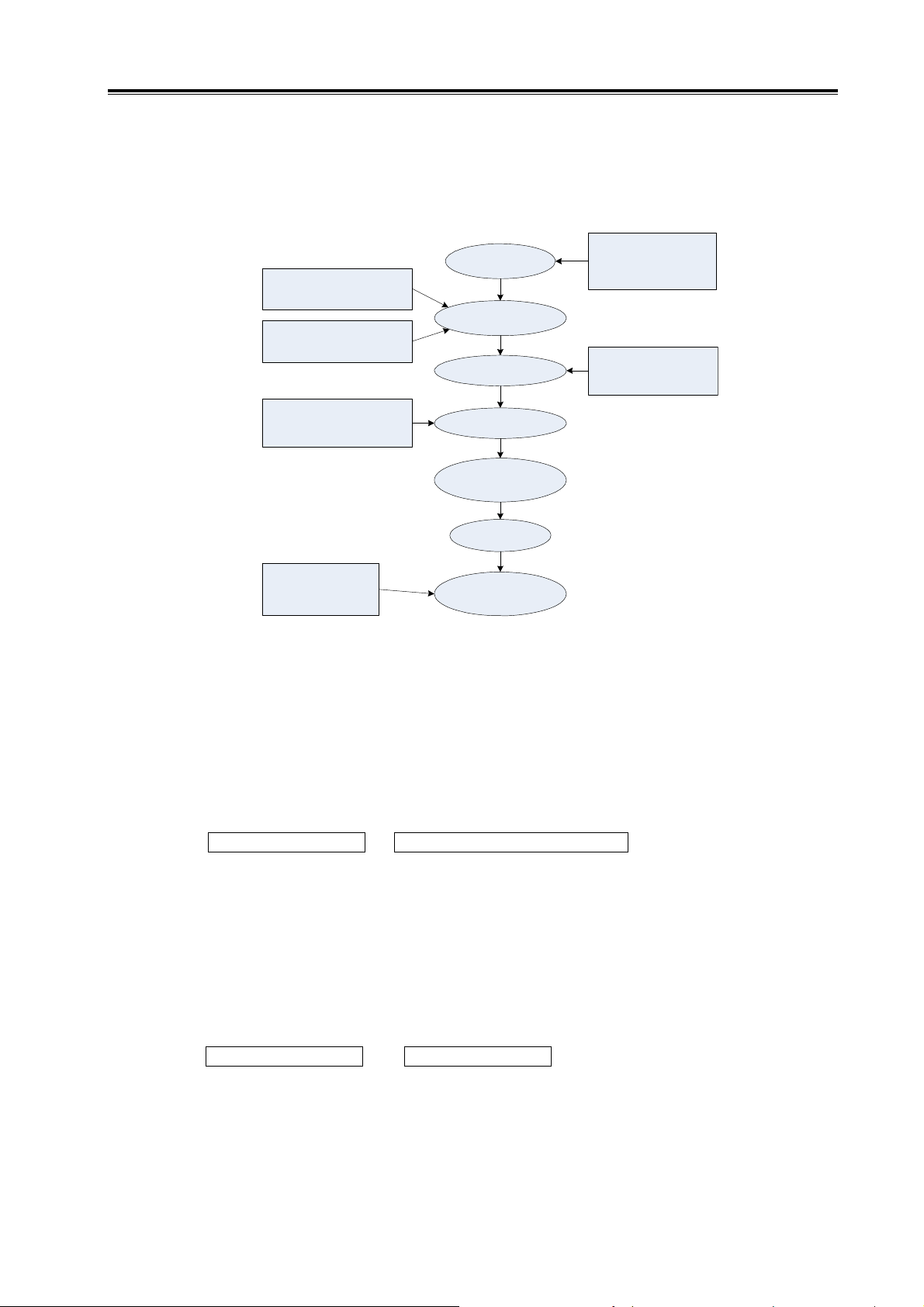
1.4.1 Model Selection Process
1.5,2.2,3.7,5.5,
7.5,11,15,18.5 are
optional (Unit: kW)
1. Low: 4500r/min;
2: Medium:7000r/min;
3. High: 10000r/min;
Rated rotation speed is
1000r/min (recommended in
turning machine)
Rated rotation speed is
1500r/min (recommended in
milling machine)
1. Flange mounting or foot
mounting;
2. With or without a keyway;
Pay attention to the
difference between
economical type and
universal type
Select motor
power
Select the rated
rotation speed
Select the max.
rotation speed
Select the
mounting method
Select the
encoder
Select the
motor model
Select the servo
unit model
After selecting the motor model, you can select the servo unit model according to the relationship
described in 1.4.2.
1.4.2 Examples
1. The model of GS Series servo device (including ZJY Series spindle servo motor) is shown as
follows:
GS servo unit model — ZJY spindle servo motor model
Example: GS3075Y-NP2—ZJY208-7.5BM -B5LY1
Instruction: the model of spindle servo unit is GS3075Y-NP2, and the corresponding model
of spindle servo motor is ZJY208-7.5BM -B5ALY1. The accessories are the
standard ones (see Section 1.4.3).
2. The model of GS Series servo device (not including ZJY Series spindle servo motor) is shown
as follows:
GS servo unit model —
Example: GS3075Y-NP2—(ZJY208-7.5BM -B5LY1)
Instruction: the model of spindle servo unit is GS3075Y-NP2, and the ex-factory parameters
should be set according to the model in the brackets. The accessories are the
standard ones (see Section 1.4.3).
(Servo motor model )
15
Page 26

GS Series Spindle Servo Drive Unit User Manual
Model list of GS Series servo unit and ZJY Series servo motor:
Servo Unit
Model
GS3048Y-NP2
GS3048Y-CP2
GS4048Y-NP2
GS4048Y-CP2
Major Parameters of Spindle Motor
Motor Model
ZJY182-1.5BH 1.5kW 1500 rpm 10000rpm 7.3 A
ZJY182-2.2BH 2.2kW 1500 rpm 10000rpm 7.5 A
ZJY208-2.2AM 2.2kW 1000rpm 7000rpm 6.7A
ZJY208-2.2BM 2.2kW 1500rpm 7000rpm 9.3A
ZJY182-3.7BH 3.7kW 1500 rpm
Rated
Power
Rated
Speed
Max. Speed
Rated
Current
7000rpm
15.5 A
(10000rpm)
Standard Encoder
1024-line
incremental
encoder
1024-line
incremental
encoder
1024-line
incremental
encoder
1024-line
incremental
encoder
1024-line
incremental
encoder
GS3050Y-NP2
GS3050Y-CP2
GS4050Y-NP2
GS4050Y-CP2
GS3075Y-NP2
GS3075Y-CP2
GS4075Y-NP2
GS4075Y-CP2
ZJY208-3.7AM 3.7kW 1000rpm 7000rpm 10.2A
ZJY208-3.7BM
3.7kW 1500rpm
(ZJY208-3.7BH)
ZJY208-5.5BM
5.5kW 1500rpm
(ZJY208-5.5BH)
ZJY208-5.5AM 5.5kW 1000rpm 7000rpm 15.5A
ZJY208-7.5BM
7.5kW 1500rpm
(ZJY208-7.5BH)
7000rpm
8.9A
(10000rpm)
7000rpm
13.7A
(10000rpm)
7000rpm
18.4A
(10000rpm)
1024-line
incremental
encoder
1024-line
incremental
encoder
1024-line
incremental
encoder
1024-line
incremental
encoder
1024-line
incremental
encoder
1024-line
16
ZJY265-7.5BM 7.5kW 1500rpm 7000rpm 18A
incremental
encoder
Page 27

Chapter I Instruction
Servo Unit
Model
GS3100Y-NP2
GS3100Y-CP2
GS4100Y-NP2
GS4100Y-CP2
GS3148Y-NP2
GS3148Y-CP2
GS4148Y-NP2
GS4148Y-CP2
GS3150Y-NP2
GS3150Y-CP2
GS4150Y-NP2
GS4150Y-CP2
Major Parameters of Spindle Motor
Motor Model
ZJY265-7.5AM 7.5kW 1000rpm 7000rpm 21A
ZJY265-11BM 11kW 1500rpm 7000rpm 26A
ZJY265-11AM 11kW 1000rpm 7000rpm 31A
ZJY265-15AM 15kW 1000rpm 7000rpm 48.3A
ZJY265-15BM 15kW 1500rpm 7000rpm 35A
Rated
Power
Rated
Speed
Max. Speed
Rated
Standard Encoder
Current
1024-line
incremental
encoder
1024-line
incremental
encoder
1024-line
incremental
encoder
1024-line
incremental
encoder
1024-line
incremental
encoder
1024-line
ZJY265-18.5BM 18.5kW 1500rpm 7000rpm 48.7A
incremental
encoder
1.4.3 Standard Ex-factory Accessories
The standard ex-factory accessories are listed in the table below. If additional accessories
are needed otherwise, please contact our sales office or technical personnels.
z GS Series MDR product accessories list
Type Name Model Number Explanation Remark
Servo unit
(separate
order
-no spindle
servo
motor)
DB-44 male plug and plastic
case
DB-25 male plug and plastic
case
DB-9 male plug and plastic case 1 CN3 connecting plug
Aluminum-shell braking resistor Including 1m connecting
1
1
CN1 connecting plug
CN2 connecting plug
line (refer to Appendix C
for the specification and
quantity)
17
Page 28

GS Series Spindle Servo Drive Unit User Manual
Type Name Model Number Explanation Remark
Servo unit
and spindle
servo
motor
Servo unit
(without
spindle
servo
motor) and
CNC
system
GS Series Spindle Servo Unit
Manual
DB-44 male plug and plastic
case
DB-9 male plug and plastic case 1 CN3 connecting plug
Motor encoder line -00-761A 1 Standard length: 3m
Motor encoder line -00-765* 1 Standard length: 3m
Motor fan line -00-768A 1 Standard length: 3m
Aluminum-shell braking resistor Including 1m connecting
GS Series Spindle Servo Unit
Manual
DB-25 male plug and plastic
case
DB-9 male plug and plastic case 1 CN3 connecting plug
Aluminum-shell braking resistor Including 1m connecting
GS Series Spindle Servo Unit
Manual
1 Technical materials
1
1 Technical materials
1
CN1 connecting plug
line (refer to Appendix C
for the specification and
quantity)
CN2 connecting plug
line (refer to Appendix C
for the specification and
quantity)
Technical materials
1
Matched
with ZJY
Series
spindle
servo motor
CN1-CNC
signal
connecting
cable is
provided
together
with CNC
system
DB-9 male plug and plastic case 1 CN3 connecting plug
CN1-CNC
signal
connecting
cable is
provided
together
with CNC
system
Servo unit,
spindle
servo
motor and
CNC
system
Motor encoder line -00-761A 1 Standard length: 3m
Motor power line -00-765* 1 Standard length: 3m
Motor fan line -00-768A 1 Standard length: 3m
Aluminum-shell braking resistor Including 1m connecting
line (refer to Appendix C
for the specification and
quantity)
GS Series Spindle Servo Unit
Manual
1 Technical materials
Note 1: A fan with 440V power should be selected to match with GS4000 Series spindle motor.
z GS Series MDR product accessories list
Type Name Model Number Explanation Remark
Servo unit,
servo
MDR20 (20pin) plug and plastic case 1 CN3 connecting plug
Motor encoder line -00-761A 1 Standard length: 3m
Servo signal
line,
18
Page 29

Chapter I Instruction
motor and
CNC
system
Motor power line -00-765* 1 Standard length: 3m; “*”
indicates the suffix letters
(see the Motor Power Line
Specification)
Aluminum-shell braking resistor Including 1m connecting
line; see Appendix C for
specification and quantity
GS Series Spindle Servo Unit Manual
1 Technical materials
GSK-CNC
communicati
on line and
terminal plug
are provided
together with
CNC system
Note 2: So far, GSK-CAN serial bus is supported in GSK988T. GS300Y-CP2 Series MDR spindle
servo unit is applicable.
1. Make clear the model, quantity of products to be ordered (servo unit, servo motor,
isolation transformer and CNC). When you need an exclusive software/hardware
version or optional accessories, write it on the order sheet.
2. Make clear the type, specification, quantity of non-standard accessories (such as special
cable or cable length, or special cable processing).
3. Make clear the code of shaft-extension, structure or leading-out pattern of servo motor.
Write special items on the order sheet.
4. When only servo unit (without servo motor) is ordered, write the model of servo model
behind the servo unit mode (for example: GS3050T-NP2
(ZJY182-3.7BH)). So that
relevant parameters can be set before delivery.
5. The spindle servo unit and servo motor with 3-phase AC440V input power are out of
stock. They are produced according to the order.
19
Page 30

GS Series Spindle Servo Drive Unit User Manual
20
Page 31

Chapter II Installation/Mounting
EFG
P
Q
L
KNA
CHAPTER II INSTALLATION/MOUNTING
2.1 Spindle Servo Motor
2.1.1 Dimensions for Spindle Motor Installation
φH
φJ
E F
T
S
φJ
G
Fig. 2-1 Flange mounting (B5)
4-φI
K
C
45°
B
φD
A
C
4-φ
Fig. 2-2 Foot mounting (B3)
E F
G
S
φJ
φH
P G
C L
4-φZ
K
45°
φD
4-φI
N
A
Fig. 2-3 Integrated Mounting (B35)
21
Page 32

GS Series Spindle Servo Drive Unit User Manual
Table 2-1 Motor Dimensions
SPEC
DIM
Eternal Dimension
ZJY208-2.
2AM
A 208 208 208 265 265 265 182 182
B 104 104 104 132 132 132
C 188 188 188 216 216 216 126 126
D 215 215 215 265 265 265 185 185
E 60 80 80 110 110 110 60 60
F 413 468 523 443 533 578 324 351
G 237 292 347 260 350 395 198 225
H 180h7 180h7 180h7 230h7 230h7 230h7 150h7 150h7
I 15 15 15 15 15 15 12 12
J 28h6 38h6 38h6 48h6 48h6 48h6 28h6 28h6
K 272 272 272 300 300 300 184 184
L 106 106 106 135 135 135 93 93
N 180 180 180 230 230 230 156 156
P 40 40 40 40 40 40 32 32
Q 210 265 320 225 315 355 132 159
S 60 80 80 110 110 110 60 60
T 5 5 5 5 5 5 4 4
Z 12 12 12 15 15 15 12 12
ZJY208-3.
7AM
ZJY208-5.
5AM
ZJY265-7.
5AM
ZJY265-1
1AM
ZJY265-1
5AM
ZJY182
-1.5BH
ZJY182
-2.2BH
DIM
Eternal Dimension
SPEC
ZJY182
-3.7BH
A 182 208 208 208 265 265 265 265 265
B 104 104 104 132 132 132 132 132
C 126 188 188 188 216 216 216 216 216
D 185 215 215 215 265 265 265 265 265
E 60 60 80 80 110 110 110 110 110
F 406 413 468 523 443 488 533 578 633
G 280 237 292 347 260 305 350 395 450
H 150h7 180h7 180h7 180h7 230h7 230h7 230h7 230h7 230h7
I 12 15 15 15 15 15 15 15 15
J 28h6 28h6 38h6 38h6 48h6 48h6 48h6 55h6 55h6
K 184 272 272 272 300 300 300 300 300
L 93 106 106 106 135 135 135 135 135
N 156 180 180 180 230 230 230 230 230
P 32 40 40 40 40 40 40 40 40
Q 214 210 265 320 225 270 315 355 410
S 60 60 80 80 110 110 110 110 110
T 4 5 5 5 5 5 5 5 5
Z 12 12 12 12 15 15 15 15 15
ZJY208
-3.7B
ZJY208
-5.5B
ZJY208
-7.5B
ZJY265
-7.5BM
ZJY265
-11BM
ZJY265
-15BM
ZJY265-
18.5BM
ZJY26522BM
22
Page 33

Chapter II Installation/Mounting
Standard Keyway Dimension
A: GB/T 1096—2003; dimension: 8×7×50; adaptable to motors ZJY182-1.5B, ZJY182-2.2B,
ZJY182-3.7B, ZJY208-3.7B. The shaft keyway dimension is shown in following figure:
2-R
5 50
60
24
0
-0.2
φ
-0.036
0
28h6
0
-0.013
8N9
B: GB/T 1096—2003; dimension: 10×8×70; adaptable to motors ZJY208-5.5B,
ZJY208-7.5B. The shaft keyway dimension is shown in following figure:
2-R
5 70
80
33
0
-0.2
0
φ
-0.036
38h6
10N9
0
-0.016
C: GB/T 1096—2003; dimension: 14×9×90; adaptable to motors ZJY265-7.5B, ZJY265-11B,
ZJY265-15B. The shaft keyway dimension is shown in following figure:
110
42.5
0
-0.2
φ 48h6
0
-0.016
2-R
7 90
2.1.2 Installation of Spindle Motor
Ambient for installation, storage and transportation:
Item Norm
Working Temperature
Storage and Transportation Temperature
Working Humidity
Storage and Transportation Humidity ≤95% (40 )℃
Atmospheric Environment No corrosive and flammable gas, oil fog or dust
Altitude Below 1000m
0
-0.043
14N9
℃~40℃
0
℃~70℃
-40
~95% (Non-condensing)
30%
23
Page 34

GS Series Spindle Servo Drive Unit User Manual
plug
¾ B5 flange mounting (or B35 flange mounting)
Motor ZJY182 adopts M10×35 Bolt or hex socket head bolt. A homemade socket head wrench
whose length is greater than that of the motor can be used to detach the robber plug on the cooling
fan. The robber plug should be pushed back after the bolt at the rear end is fastened. Shown as
follows:
Homemade
Bolt
Robber plug
Motor ZJY208 and ZJY265 adopt M12×45 Bolt or hex socket head bolt.
¾ B3 foot mounting (or B35 foot mounting)
Detach the covers of two sides at the rear end. For B35, it is needed to detach the robber plug on
the foot hole (see the following figure). Motor ZJY182 and ZJY208 adopt M10 Bolt or hex socket head
bolt; ZJY265 adopts M12 Bolt or hex socket head bolt.
24
Robber
The covers at two sides of the rear end should be mounted after the motor is firmly
fixed; otherwise, the cooling effect will be reduced as a result of air leak, thus causing
motor overheat.
1. If the motor running speed needs to be more than 2000r/min, a motor with smooth shaft
is recommended. Fasten the belt pulley with keyless locking device. Both of them have
undergone the dynamic balancing and meet the requirement of G1; otherwise, great
vibration will occur during high-speed running.
2. Reserve a certain space near outlet box cover for the convenience of screw detaching
and wiring. Please contact us if you cannot do it by yourself. Do not change the structure of
the motor.
Page 35

Chapter II Installation/Mounting
g
Prevent the motor from direct sun light and rain splash. The mounting parts need
to be ventilated, dampproof and dust-proof.
Avoid flammable atmosphere in case of fire disaster.
Do not strike the spindle motor with hard objects during installation and
dismantling.
There are fragile components in the
encoder. Do not subject the
encoder to any force or shock
during installation!
Do not subject the
wheel belly to any
force or shock
durin
installation!
2.2 Spindle Servo Unit
The installation ambient greatly affects the servo unit function and life cycle; please pay
attention to the following cautions:
Caution
Storage and Transportation Temperature
Storage and Transportation Humidity
z Avoid rain splash and direct sunlight.
z
Install the servo unit in electrical cabinet to avoid the invasion of dust,
corrosive gas, conductive contents and combustibles.
z
The mounting parts need to be ventilated, dampproof and dust-proof.
z
Avoid flammable atmosphere in case of fire disaster.
z
Select a proper installation position for easy maintaining and inspection.
Item Norm
Working Temperature
Working Humidity
Atmospheric Environment No corrosive and flammable gas, oil fog or dust
Altitude Below 1000m
Vibration ≤0.6G(5.9m/s2)
Atmospheric Pressure
℃~40℃
0
-40
℃~70℃
30%
~95% (Non-condensing)
≤95%
(40℃)
86kPa
~106kPa
25
Page 36

GS Series Spindle Servo Drive Unit User Manual
2.2.1 Installation Dimension
The dimensions of GS Series spindle servo unit are shown as follows:
Fig. 2-4 GS3048, GS4048 Series installation dimension (Unit: mm)
2- 6
6
Series
AC Servo Motor Drive Unit
CHARGE
POWER
C
N
3
C
N
2
258±0.25
C
N
1
C
N
4
C
N
5
2-R3
6
108±0.2
218
120
Fig. 2-5 GS3050, GS4050 Series installation dimension (Unit: mm)
270
26
Page 37

6
2- 6
Chapter II Installation/Mounting
Series
AC Servo Mo to r Dr iv e Un it
CHARGE POWER
C
N
3
C
N
2
C
N
1
305
293±0.25
C
N
4
C
N
5
2-R6
6
118±0.2
130
248.5
Fig. 2-6 GS3075, GS4075 Series installation dimension (Unit: mm)
2-φ6
6
Series
AC Servo Motor Drive Unit
C
N
3
C
N
2
305
273.5
2-R3
C
N
1
C
N
293±0.25
4
C
N
5
148
160
Fig. 2-7 GS3100, GS3148, GS4100, GS4148 Series installation dimension (Unit: mm)
27
Page 38

GS Series Spindle Servo Drive Unit User Manual
Fig. 2-8 GS3150, GS4150 Series installation dimension (Unit: mm)
2.2.2 Installation Intervals
GS Series spindle servo unit is installed vertically on the motherboard with the front side
facing forward and top side facing upward. Enough intervals should be reserved.
28
Fig. 2-9 Minimum intervals of GS3048, GS4048 Series spindle servo unit installation
Page 39

Chapter II Installation/Mounting
Cabinet
mm
100
Wiring
space
Up
Front
100 mm
Heat
Cabinet
CHARGE
POWER
100 mm
C
N
3
C
N
2
Installation Surface
50mm
Cooling
air
Heat
C
N
1
C
N
4
C
N
5
100 mm
Down
Fig. 2-10 Minimum interval of GS3050, GS4050 Series spindle servo unit installation
Front
Radiator from which cool air blows to the servo unit should be installed in the electric
cabinet in case of the increase in temperature.
Cabinet
Heat
100mm
Cooling
air
Heat
CHARGE POWER
100mm
100mm
C
N
3
C
N
2
C
N
1
C
N
4
C
N
5
60mm
Cabinet
Installation Surface
mm
100
Wiring
space
Down
Up
Fig. 2-11 Minimum interval of GS3075, GS4075 Series spindle servo unit installation
29
Page 40

GS Series Spindle Servo Drive Unit User Manual
Cabinet
Cabinet
Heat
100mm
Front
100mm
C
N
3
60mm
C
N
2
Installation Surface
Cooling
air
Heat
100mm
C
N
1
C
N
4
C
N
5
Fig. 2-12 Minimum interval of GS3100, GS3148, GS4100, GS4148 Series spindle servo unit
mm
100
Wiring
space
Down
Up
Front
80mm
Cabinet
120mm
CHARG
E
installation
Cabinet
Heat
Installation Surface
Up
mm
80mm
POWE
R
R
S
T
P
B
U
V
W
C
~380V
N
3
C
N
BRAKE
2
MOTOR
C
N
1
C
N
4
C
N
5
~380V
r
t
100
Wiring
space
Down
120mm
Cooling air
Fig. 2-13 Minimum interval of GS3150, GS4150 Series spindle servo unit installation
When more than one servo units are installed, enough intervals should be reserved for well
radiating.
30
Page 41

Chapter III Connection
CHAPTER III CONNECTION
The following cautions should be read carefully and observed strictly so as to ensure safe
and success operation.
The connection should be done by professional personnel according to relevant instructions.
Connection or inspection should be done 5min later after the servo unit is power-off and the
grounding voltage of main circuit terminal is confirmed to be safe; otherwise, it is easy to get
electric shock.
Ensure that the servo unit and servo motor are properly grounding.
Wire layout should be carefully done to avoid pointed objects. Cables should not be dragged
by force; otherwise, it is easy to lead to electric shock or poor connection.
Do not lay the main circuit and the signal line in one pipe nor bound them together. They
should be laid independently or crossly, and the distance should be over 30cm, thus to prevent
high voltage circuit’s interference to signals and ensure normal working of the servo unit.
Do not turn ON or OFF the power frequently. Since in the spindle servo unit, there is large bulk
capacitance which will generate large charging current at power-on, frequent ON/OFF
switching will cause performance degradation on inner components. It is advised that the
interval between power ON and OFF should be more than 3min.
Devices such as power capacitor, surge absorber and radio noise filter should not be installed
between spindle servo unit output side and serve motor side.
The main circuit and signal lines should be kept away from radiator and motor in case of
insulation performance degradation because of heating.
After the main circuit is connected, the terminals should be protected by a cover to avoid
electric shock.
31
Page 42

GS Series Spindle Servo Drive Unit User Manual
3.1 Connection of Peripheral Equipments
Some peripheral equipments are needed for the running of spindle servo unit. Proper
peripheral equipments ensure the stable running of servo unit and servo motor and prolong the
life cycle.
In the connection diagram, the following points should be noted:
z The equipments in the dashed box are free to choose; the equipments in the solid line
box are available from GSK.
z The selections for circuit breaker, AC filter, isolation transformer, AC reactor and AC
contactor are described in Appendix B.
z Refer to Appendix C for the selection of braking resistor.
z The equipments marked with “essential” can ensure safe and reliable operation of the
servo unit and minimize the loss to the greatest extent when fault occurs.
z The equipments marked with “optional” can ensure stable running in poor power supply
environment.
32
Page 43

Chapter III Connection
z Peripheral equipments connection of Series (D-SUB type) GS3048Y-N, GS3050Y-N,
GS3075Y-N, GS3100Y-N, GS3148Y-N and Series GS4048Y-N, GS4050Y-N,
GS4075Y-N, GS4100Y-N, GS4148Y-N should be done according to the following figure;
as for the later group of Series products, L1, L2, L3 should be connected to 3N
50/60Hz 440V.
L3L2L1
3N~50/60Hz 380V
Circuit breaker
(essential)
2nd position
feedback (CN3)
Filter (optional)
AC Reactor (optional)
AC Contactor
(essential)
CNC System
R
S
T
P
B1
B
U
V
W
r
t
~
380V
BRAKE
MOTOR
~
380V
R
i
e
r
e
S
s
v
e
i
r
D
r
o
o
t
M
o
v
r
e
S
C
A
t
i
n
U
Optional
E
G
R
A
H
C
R
E
W
O
P
C
N
3
C
N
2
C
N
1
~
PE
Control circuit (see
Section 3.2.1)
Cooling fan
line
Motor
power line
Braking resistor (essential)
External braking resistor to P, B;
B1 to none;
High temperature! Do
not touch!
Fig. 3-1 (a) Connection diagram of GS Series spindle servo unit (D-SUB type) peripheral equipments
33
Page 44

GS Series Spindle Servo Drive Unit User Manual
z Peripheral equipment connection of Series (D-SUB type) GS3150Y-N and Series
GS4150Y-N should be done according to the following figure; as for the later Series, L1,
L2, L3 should be connected to 3N
~50/60Hz 440V.
Fig. 3-1 (b) Connection diagram of GS Series spindle servo unit (D-SUB type) peripheral equipments
34
Page 45

Chapter III Connection
z Peripheral equipments connection of Series (MDR type) GS3048Y-C, GS3050Y-C,
GS3075Y-C, GS3100Y-C, GS3148Y-C and Series GS4048Y-C, GS4050Y-C,
GS4075Y-C, GS4100Y-C, GS4148Y-C should be done according to the following figure;
as for the later group of Series, L1, L2, L3 should be connected to 3N
~50/60Hz 440V.
Fig. 3-2 (a) Connection diagram of GS Series spindle servo unit (MDR type) peripheral equipments
35
Page 46

GS Series Spindle Servo Drive Unit User Manual
z Peripheral equipments connection of Series (MDR type) GS3150Y-C and Series
GS4150Y-C should be done according to the following figure; as for the later Series, L1,
L2, L3 should be connected to 3N
~50/60Hz 440V.
Fig. 3-2 (b) Connection diagram of GS Series spindle servo unit (MDR type) peripheral equipments
36
Page 47

Chapter III Connection
3.2 Connection of Main Circuit
3.2.1 Connection
z Example of GS3□□□ Series spindle servo unit main circuit connection
z The input power of GS4□□□ Series spindle servo unit and motor cooling fan is 3N~
50/60Hz 440V.
Fig. 3-3 GS Series spindle servo unit main circuit connection
Not all the motor’s U, V, W phase sequences are corresponding to the U, V, W of
drive unit. If Err-27 occurs during the first running, it means the phase sequence are
incorrect (not drive unit fault). Turn OFF the power for 5 min and exchange any of
the two phases.
The equipments in the dashed box are optional. When the ambient condition cannot
guarantee the normal running of drive unit, these equipments can be installed (refer
to Appendix B).
The minimum power of DC switching power supply (15V-24V) specified externally
should not be less than 35W.
The grounding resistance should be less than 10Ω.
37
Page 48

u
n
R
UTer
t
3
c
d
U
b
v
n
p
g
y
t
d
Cable
diameter
5
5
5
a
m
GS Series Spindle Servo Drive U
it User Manual
3.2.2 Wiring of Main Circ
Terminal
Mark
R, S, T
U, V, W
B, P
PE
It is advised that the cables a
Name
AC power input
terminal
Three-phase AC
output terminal
Braking resistor
terminal
Protective
grounding terminal
it
Description
Three-phase AC power in
Connected to three-phase windin
The braking resistor is used for dyna
The spindle servo unit works normally onl
resistor is externally connec
The protective grounding resistance shoul
d terminals meet the following requirements:
, S, T,
, V, W
r, t P, B
ut
U, V, W
mic braking;
when the braking
ed.
be less than 10Ω.
PE
Model Motor Power
Bol
GS3048
GS4048
GS3050
GS4050
GS3075
GS4075
GS3100
GS4100
GS3148
GS4148
GS3150
GS4150
1.5kW, 2.2kW,
3.7kW,
3.7kW, 5.5kW
5.5kW,7.5kW
7.5kW,11kW
11kW
15kW, 18.5kw
3.2.3 Servo Motor Conne
Cable diameter
minal
Size
mm
φ
.5
4
6 4 4 1 6 2.
6 6 4 1 6 4
6 6 4 1 6 4
6 10 4 1 6 4
mm
2
2.
5
2.
5
Terminal
Bolt Size
φmm
3.5 1 3.5 2.
4 1 4 2.
mm
2
Cable diameter
Terminal
Bolt Size
φmm
mm
2
4 2.5
5 2.5
5 2.5
tion Instruction
Terminal
Bolt Size
φmm
6 4
6 4
6 6
mm
2
Cable diameter
z Instruction of ZJY spin
The three-phase winding
glands. Their position in terminal
to U, V, W, and PE terminal of ser
from motor shaft extension side to
38
le servo motor terminal box:
, V, W and the casing (grounding) are lead ou
ox is shown in following figure. U, V, W and c
o unit main circuit respectively. The wind fro
the end. Three-phase AC power supply is con
t through cable
sing are connected
cooling fan blows
nected externally.
Page 49

Chapter III Connection
(See Section 1.2.1 for the voltage level)
ZJY208, ZJY265 Series Motor Terminal Box ZJY182 Series Motor Terminal Box
When the spindle servo unit is matched with a different servo motor, the U, V,
W of drive unit may be different from the U, V, W of the motor. If the motor rotates, at a certain
uncontrollable speed, and Err-7 occurs, it means the phase sequences are not consistent. Please
turn OFF the power for 5 minutes, and exchange any two of the U, V, W phases.
z Connection of encoder signal receptacle pins
The leading wire of ZJY182 Series servo motor incremental encoder is lead out through
the 12-pin male plug, shown as follows: (refer to Section 3.4.1 for the leading wire connection
diagram)
Male plug drawing (back view)
39
Page 50

GS Series Spindle Servo Drive Unit User Manual
Encoder Pin
Casing
VCC
GND A
A
B
B
Z
Z
(PE)
Pin No. 1
9 5 6 10 7 11 8 12
The industrial female receptacle (aviation) of encoder signal line of ZJY208 Series, ZJY265
Series servo motor is shown in following figures:
2
5
10
13
Receptacle
(welded side)
1
1415
3
6
11
Casing
Encoder Pin
VCC GND A
A
B
B
Z
Z
(PE)
Pin No. 1 2 3 4 7 5 8 6 9
3.3 Connection of Control Signal
3.3.1 CN1 Control Signal
z Layout of GS Series D-SUB type CN1 pins
The control signal interface CN1 of GS Series D-SUB product is 44-pole female receptacle. The
connector is 44-pin male plug (model G3101-44MBNS1X1, provided by WIESON). The pin
description is shown in following figure:
40
Page 51

Position feedback
PZ output
Digital
ground
Speed selection 1 (or position
deviation clear) input
Speed selection 2 (or pulse
command inhibition) input
Alarm clear
input
Zero speed
clamping input
Control mode
switching input
External power input (15~
24VDC)
Servo ready
output
Position arrival (or speed
arrival) output
Zero speed
signal output
Analog
ground
Analog speed
command input +
Chapter III Connection
PZO+
PZO-
DGND
SEC1/CLE
SEC2/INH
ALRS
ZSL
PSTI
COM+
SRDY
PSR
ZSP
AGND
VCMD+
31
32
33
34
35
36
37
38
39
40
41
42
43
44
16
SIGN-
1
17
18
19
20
21
22
23
24
25
10
26
11
27
12
28
13
29
14
30
15
SIGN+
2
PULS+
PBO+
3
PAO+
4
SFR
5
SRV
6
GAIN
7
SON
8
OSTA
COM-
9
ALM+
PSTO+
PSTO-
COIN+
COIN-
ZOUT+
VCMD-
Pulse command
PULS-
PBO-
PAO-
BREF
Position feedback PB
Position feedback PA
CCW rotation enable input
CW rotation enable i nput
Spindle clamping interlock sign al input
Speed loop gain 2 selection input
NC
NC
Servo enable input
Orientation enable input
(15~24VDC) reference ground
ALM-
Alarm output
Control mode switching
completed output
NC
NC
completed output
NC
NC
Z pulse output
Analog speed
command input
ZOUT-
input
output
output
Orientation
Fig. 3-4 CN1 pins diagram
The control signal interface CN1 of GS Series MDR product is 50-pole female receptacle (model
MDR10150-3000-PE, provided by 3M). The pin description is shown in following figure:
41
Page 52

GS Series Spindle Servo Drive Unit User Manual
PBO-
PAO-
PULS-
SEC2
/INH
BREF
SFR
SON
PSR+
SRDY+
PSTO+
ZSP+
ALM+
VCMD-
Position
feedback PB
output Position
feedback PA
output -
Pulse
command
pulse input -
Speed selection 2
(or pulse comman d
inhibition) input
Spindle clamping
interlock signal
input
CCW rotation
enabled input
Servo enable
input
Position arrival
(or speed
arrival) output +
Servo ready
output +
Control mode
switching completed
output +
Zero speed
signal output +
Servo alarm
output +
Analog speed
command -
PZO+
/
SIGN+
NC
PSTI
OSTA
COM+
COM+
NC
COIN+
ZOUT+
NC
Position
feedback PZ
output +
Pulse command
direction input +
Control mode
switching input
Orientation
enable input
External
power input
(15~24VDC)
External
power input
(15~24VDC)
Orientation
completed
output +
Z signal
output +
27
29
31
33
35
37
39
41
43
45
47
49
1
PBO+
PAO+
PULS+
SEC1
/CLE
SRV
ALRS
COM-
SRDY-
PSTO-
ZSP-
ALM-
VCMD+
Position
feedback output
Position
feedback PA
output +
Pulse
command
pulse input +
Speed selection 1
(or position deviat ion
clear) input
CW rotation
enabled input
Alarm clear
input
(15~24VDC)
reference ground
Servo ready
output -
Control mode
switching completed
output -
Zero-speed
signal output -
Servo alarm
output -
Analog speed
command +
3
5
7
9
11
13
15
17
19
21
23
25
2
4
6
8
10
12
14
16
18
20
22
24
26
28
30
32
34
36
38
40
42
44
46
48
50
Position feedback
PZO-
PZ output -
DGND
SIGN-
NC
ZSL
GAIN
COM-
PSR-
NC
COIN-
ZOUT-
AGND
NC
Digital ground
Pulse command
direction input -
Zero speed
clamping input
Speed loop
gain 2 selection
input
(15~24VDC)
reference ground
Position arrival
(or speed
arrival) output -
Orientation
completed
output -
Z signal
output -
Analog
ground
Fig. 3-5 CN1 pins diagram
z I/O signal comparison between D-SUB type and MDR type
P: Position Control S: Speed Control
GS D-SUB Interface GS MDR Interface
Type
Signal Pin No. Signal Pin No.
Common port of Input point; the input
port of external DC power 15~24V
Connected to external DC 15V~24V
P, S
+ 39 COM+ 39, 41
COM
COM- 24 COM- 14, 38
SON 23 SON 13 Servo enable input 3.3.4
ALRS 36 ALRS 12 Alarm clear input 3.3.4
VCMD
VCMD
+
-
44
14
VCMD
VCMD
+
-
24
25
Analog speed command input 3.3.2
AGND 43 AGND 48 Analog ground \
PA6=1, CCW rotation enable input;
PA6=0, drive unit enable permit input;
PA6=1, CCW rotation enable input;
S
SFR 20 SFR 11
SRV 5 SRV 10
ZSL 37 ZSL 34 Zero speed clamping input 6.5.4
OSTA 8 OSTA 37 Orientation enable input 6.5.1
S SEC1
SEC1
34
P CLE CLE
S SEC2
SEC2
35
P INH INH
8
7
For internal speed selection function:
For position control: position deviation
For internal speed selection function:
For position control: pulse command
P BREF 21 BREF 9 Spindle clamping interlock signal input; 6.6
Function Reference
power ground.
PA6=0, invalid;
speed selection 1;
clear
speed selection 2;
inhibition
\
\
5.2.1
5.2.1
5.2.2
6.4.3
5.2.2
6.4.4
42
Page 53

Chapter III Connection
PULS
PULS
SIGN
SIGN
+
-
+
-
6
5
31
30
Position command pulse input
① Pulse + direction
② CCW pulse+ CW pulse;
③ A/B phase pulse;
3.3.3
P
+
PULS
-
PULS
SIGN+
-
SIGN
2
17
1
16
P, S GAIN 6 GAIN 36 Speed loop gain 2 selection input 6.1.2
S/P PSTI 12 PSTI 35
ALM+
ALM-
SRDY 40
PSTO+
PSTO-
P, S
S
P, S PSR 41
ZOUT+
-
ZOUT
PAO+
-
PAO
PBO+
-
PBO
PZO+
-
PZO
ZSP 42
COIN+
COIN-
9
25
10
26
13
29
19
4
18
3
31
32
12
28
ALM+
ALM-
SRDY+
SRDY-
PSTO+
PSTO-
ZOUT+
ZOUT-
PAO
+
-
PAO
PBO
+
-
PBO
PZO
+
-
PZO
ZSP+
ZSP-
COIN+
COIN-
PSR+
PSR-
23
22
17
16
19
18
47
46
4
3
2
1
27
26
21
20
45
46
15
40
Speed / position switching (it is valid
when PA4=5)
Alarm output 3.3.5
Servo ready signal output 3.3.5
Control mode switching completed
output
Position feedback Z pulse signal OC
output
Position feedback signal output
Refer to parameters PA69~71
Zero speed signal output 3.3.5
Orientation completed output 6.5.1
Position arrival output in position mode 6.4.2
Speed arrival output in speed mode 6.5.3
5.4
\
3.3.5
3.3.6
3.3.2 Speed Command Input
VCMD+/VCMD- is the input port of speed command. It can receive 10V DC voltage signal. The
input impedance is 15kΩ. The following figures are two examples of connection.
43
Page 54

GS Series Spindle Servo Drive Unit User Manual
Note: VCMD+, VCMD- cannot be
connected in reverse; otherwise
-10V~+10V
or
0V~10V
the motor cannot run normally.
PC
VC
~
0V
VCMD+
VCMD-
Servo Unit
R
R
R
0V
Metal shelled
:
PE
1. When the external analog command taken as speed command, it is easily affected by
external environment, thus causing vibration of the servo motor. Therefore, the analog
command signal line should be shielded with twisted pair.
2. The shielding wire connection method in the above figure is recommended, but it is
not used universally.
3.3.3 Position Command Input
There are three position command input modes set by PA5 (see the following table). The arrow
indicates the counting edge.
PA28 sets the reversed position command direction. It can change the rotation direction of the
motor.
command
Pulse train
direction
CCW pulse
CW pulse train
A phase pulse
B phase pulse
Pulse
mode
train
train
train
PULS
SIGN
PULS
SIGN
PULS
SIGN
Standard Mode:PA28=0
CCW CW
PA5 setting value
PA5=0
Command pulse+
direction
PA5=1
CCW pulse + CW
pulse
PA5=2
A/B phase
command pulse
44
Page 55

Chapter III Connection
a, Pulse + Direction: pulse input sequence diagram (maximum pulse frequency 1MHz)
PULS
SIGN
90%
10%
90%
10%
th
trh trl
CW
ts
trh
tck
CCW
tl
ts
trl
CW
b, CCW pulse /CW pulse: pulse input sequence diagram (maximum pulse frequency 1MHz)
tck
th
90%
PULS
SIGN
10%
trh t rl
90%
10%
CCW
tl
ts
trh
rl
t
CW
c, two-phase command pulse: input sequence diagram (maximum pulse frequency 1MHz)
tqck
tqh
90%
PULS
10%
tqs
tqrh
90%
SIGN
10 %
t qrl
t qrl
tqs
tql
tqrh
CCW CW
45
Page 56

GS Series Spindle Servo Drive Unit User Manual
The following table lists the parameters about the pulse input sequence:
t
PAR.
th t
ck
trh trl ts t
l
qck
tqh tql t
qrh
t
tqs
qrl
Differential
>1 >0.3 >0.3 <0.2 <0.2 >2 >1 >0.3 >0.3 <0.2 <0.2 >0.2
input
(μs)
Single-ended
>5 >2.5 >2.5 <0.3 <0.3 >2.5 >10 >5 >5 <0.3 <0.3 >2.5
input
(μs)
The position command connection adopts differential connection or single-ended connection.
Shown as follows:
z Differential connection
z Single-ended connection
4.7kΩ resistor is connected in
PC
Pulse command
input
case of strong interference
V
R
PULS+
PULS-
270
Drive Unit
4.7K
270
4.7K
NPN
SIGN+
R
SIGN-
4.7kΩ resistor is connected in
case of strong interference
:
Metal shelled
PE
46
PC
PNP
Pulse command
V
input
(a) NPN single-ended connection
4.7kΩ resistor is connected in
case of strong interference
R
R
4.7kΩ resistor is connected in
case of strong interference
PULS+
PULS -
SIGN +
SIGN -
270
270
PE
(b) PNP single-ended connection
Drive Unit
4.7K
4.7K
Page 57

Chapter III Connection
¾ It is advised to adopt differential connection to enhance the anti-interference
capability; AM26LS31, MC3487 or driver chips similar with RS422 are
recommended as interface circuit.
¾ The use of the single-ended mode will lower down the action frequency. The current
is 10mA~15mA according to pulse input circuit. Limit the external power voltage to
25V and determine the value of resistance R. Empirical data: VCC=24V, R=1.3 kΩ
2kΩ; VCC=12V, R=510Ω~820Ω; VCC=5V, R=0Ω
3.3.4 Digital Input
The following figures are examples of common-used connection; INx represents the input point:
SON, ALRS, SFR, SRV, SEC1, SEC2, ZSL, OSTA, GAIN, PSTI, BREF.
Externally digital
input
Externally connect
optical coupler
~
There is not 24V power output. It should be externally equipped. The specification
requirement is DC15V
supply as with output circuit.
When the input signal INx is connected to 0V, the input optical coupler conducts. The signal INx
is ON, and the input is valid. It can be checked through
is ON, the input is valid; if it is OFF, the input is invalid. In this case, the corresponding circuit should
be check for troubleshooting.
The status of monitoring contents is:
~24V, above 100mA. It is recommended to use the same power
. If the corresponding LED digit light
47
Page 58

GS Series Spindle Servo Drive Unit User Manual
SON and ALRS are general input signal. The sequence is shown as follows: (refer to Chapter 6
for the sequence of other signals)
¾ When SON is ON, the servo enable is ON,
under monitoring menu
.
Relevant
Meaning Unit
Parameter
When PA118=1, servo internal
enable; SON signal is not detected;
PA118
PA118=0, servo enable signal is
given by SON.
1. In position mode, manual mode, JOG mode and speed mode (when internal digital
command is valid):
2. Speed mode in which the -10V~10V analog command is valid, i.e., PA6=0:
will be displayed after
Default
Value
is pressed
Applicable
Mode
0 P, S
3. Speed mode in which the 0-10V analog command is valid, i.e., PA6=1:
48
Page 59

Chapter III Connection
If the spindle servo unit is faulty, the motor cannot be energized.
An alarm will be displayed in the monitoring window of spindle servo unit.
¾ When SON is OFF, and ALRS jumps from OFF to ON, the number 1~9 alarms can be reset.
The alarms whose number is larger than 9 can be automatically reset after power-on again.
When SON is ON, the ALRS signal function invalid.
3.3.5 Digital Output
1. Among the GS Series D-SUB product digital output signals, signals ALM, SRDY, ZSP
are single-ended transistor output. The output optical coupler emitter has been connected
to COM-. Other output signals are double-end transistor output.
2. Please note that some GS Series D-SUB products digital output signal and GS Series
MDR products digital output signals are double-end transistor output.
SON
ALM
ALRS
OFF ON
No
alarm
Alarm Alarm
OFF ON OFF
20ms
No
alarm
ON
z The connectivity of single-ended transistor output
Example1: applicable to 980TDa CNC system
Controller externally connected
Example 2: applicable to 983M CNC system
49
Page 60

GS Series Spindle Servo Drive Unit User Manual
Relay externally
connected
z Connectivity of double-end transistor output
Controller externally connected
Relay externally
connected
When the output signal OUTx and COM- conduct, or OUTx and OUTx conduct, the output
signal is ON. It can be known from the monitoring window
. When the output signal is
ON, the corresponding LED light will come ON; when the output signal is OFF, the LED light will
come OFF.
50
¾ ALM is the output signal when abnormality is detected in the servo unit. The output
status is related to parameter PA122.
Page 61

Chapter III Connection
PA122=0 When an alarm is issued in servo unit, the ALM signal output optical coupler is OFF.
PA122=1 When an alarm is issued in servo unit, the ALM signal output optical coupler conducts.
¾ SRDY servo unit ready signal; when the motor is energized, the output optical coupler
of this signal conducts.
¾ ZSP is zero speed output; when the motor running speed is less than the setting value
of PA62, the output coupler of this signal conducts.
ZOUT+/ZOUT- are position feedback output Z pulse signal, i.e., the one-rotation signal;
PA33=1: Select the motor encoder Z pulse signal which is input by CN2;
nd
PA33=1: Select the Z pulse signal of 2
Servo Unit
position feedback signal which is input by CN3.
ZOUT+
ZOUT-
+24V
nPC
CNC
System
R
0V
Caution
1. The output signal is of open collector. The maximum load current is 100mA; the
maximum voltage of external DC power is 25V. If these requirements are not met or
the output signal is connected to power directly, the servo unit will be damaged.
2. If the load is inductive. FWD (free wheeling diode) should be connected in series at
two ends of the load; if the connection is reversed, the servo unit will be damaged.
51
Page 62

GS Series Spindle Servo Drive Unit User Manual
3.3.6 Position Signal Output
The PAO+/PAO-, PBO+/PBO-, PZO+/PZO- are the position signals output from the servo unit in
differential form. The signal is output position signal in proportion as 1:1 after the servo unit processes
the position signal which is input by CN2 and CN3 and feedbacked by encoder.
Output Form Position Signal Name Function
Differential output
Differential output
Differential output
Relevant
Parameter
PAO
+/PAO-
PBO
+/PBO-
PZO
+/PZO-
Name
Position feedback input signal
selection
A phase of encode feedback signal
B phase of encoder feedback signal
Z phase of encoder feedback signal
Parameter
Range
~1
0
Default
Value
Applicable
Mode
0 P, S
PA97
PA97=0, select the 2
nd
position input signal as the position input signal; CN3 must
be connected to the feedback signal of the 2
will occur in the servo unit.
Position output signal selection
PA33=1, select the motor encoder signal as the position input signal;
PA97=1, select the motor encoder signal as the position input signal;
PA33
PA33=0, select the 2
nd
position input signal as the position input signal; CN3 must
be connected to the feedback signal of the 2
will occur in the servo unit.
PA34 Position output signal reversed
52
nd
position encoder; otherwise, Err-24
0
~1
nd
position encoder; otherwise, Err-24
~1
0
0 P, S
0 P, S
Page 63

Chapter III Connection
PA34=0, maintain the original relationship of CN1 position feedback output signal;
PA34=1, reverse the phase relationship of PA, PB. Shown as follows:
For example: When the position input signal is the TAMAGAWA incremental encoder signal, its
form is:
t
e=t±
Then, the position signal output wave includes two types:
-
2
The connectivity is:
Differential output
connected
externally
High-speed optical
coupler connected
externally
3.4 Connection of Position Feedback Signal
3.4.1 Motor Encoder Position Feedback Signal Interface CN2
53
Page 64

GS Series Spindle Servo Drive Unit User Manual
z Interface CN2 of GS Series D-SUB servo unit
The interface CN2 is 25-pole female receptacle, therefore the connector should be 25-pin
male plug (type is G3151-25MBNS1X1, provided by WIESON company). The pin definition is
shown as follows:
1
34 89572
6
10 11
12 13
14 15
16
17
18 19
20
21
22 23
24
25
Fig. 3-6 CN2 DB 25-pole female receptacle drawing
Pin No. Name Meaning Pin No. Name Meaning
1 0V
2 0V 15 FG
3 0V 16 0V
4 0V 17 5V
5 5V
6 5V 19
7 W-
8 V-
9 U-
10 Z-
-
11
12
13 OH
B
-
A
Encoder power supply
(-)
Encoder power supply
(+)
Incremental encoder
feedback W-
Incremental encoder
feedback V-
Incremental encoder
feedback U-
Incremental encoder
feedback Z-
Incremental encoder
feedback B-
Incremental encoder
feedback A-
Motor temperature
sensor input end
14 FG
18 5V
+
W
20 V
21 U
22 Z
23 B
24
25 NC
+
+
+
+
A+
Shielding ground
Encoder power
supply (-)
Encoder power
supply (+)
Incremental
encoder feedback
W+
Incremental
encoder feedback
V+
Incremental
encoder feedback
U+
Incremental
encoder feedback
Z+
Incremental
encoder feedback
B+
Incremental
encoder feedback
A+
z Interface CN2 of GS Series MDR servo unit
The interface CN2 is 26-pole female receptacle, therefore, the connector should be 26-pin
male plug (the type is MDR10126-3000-PE, provided by 3M Company). Shown in the following
figure:
14
15
1
234
19
17
56789
21
23
10
11
26
25
13
12
24
22
20
18
16
Fig. 3-7 CN2 MDR male plug drawing (welded side)
54
Page 65

Chapter III Connection
Pin No. Name Meaning Pin No. Name Meaning
1 OH
2 NC
3 NC 16 0V
4 NC 17 0V
5 NC 18 NC
6 NC 19 5V
7 NC 20 5V
8 Z+ 21 5V
9 Z- 22 NC
10 B+ 23 MA+
-
11
12
13
B
+
A
-
A
Motor temperature
sensor input end
Incremental encoder
feedback signal
14 BAT3V6
15 0V
24
25
26
MA-
SL+
SL-
Power supply
Encoder power (-)
Encoder power (+)
Absolute encoder feedback
signal
z Position input signal connection circuit
1. Incremental encoder feedback signal line adopts differential connection; the connectivity
is shown as follows:
Encoder
X+
X-
Servo Unit
120
Ω
AM26LS32
X=A、B、Z、U、V、W
2. The input circuit of absolute encoder feedback signal is 4-channel differential bus
transceiver which meets the requirements of ANSI EIA/TIA-422-B and RS-485 standard. The
connectivity is shown as follows:
Servo UnitEncoder
RS-485
DATA+ SL+
DATA-
SL-
3. OH is used to connect the overheat detector in servo motor, thus motor overheat
protection function can be controlled by the servo unit. The connectivity is:
55
Page 66

GS Series Spindle Servo Drive Unit User Manual
If there is no motor temperature sensor, this signal is not connected.
z Connection of motor encoder line
Caution
1. The following figure is the standard diagram of GS Series D-SUB spindle servo unit and
1. The length of motor power line and motor encoder feedback signal line should be
within 20m, and the distance of the two lines should be more than 30cm. These two
lines cannot be in the same pipe or bound together.
2. Stranded shielding cable should be used as the signal lines and the cross section of
line should be 0.15mm
terminals.
2
~0.20mm
2
; The shielding layer must be connected with PE
incremental motor encoder connection. When other feedback signal line is used, this
diagram can also be a reference.
24
A+
12
A-
23
B+
11
B-
Z+
22
Z-
10
13 OH
0V
16
5V
5
5V
6
5V
17
5V
18
0V
1
2
0V
0V
3
0V
4
14
PE
15
PE
Metal Shell
CN2 Economical Spindle Servo Unit
ZJY Spindle Servo Motor Encoder
A+
4
A-
7
B+
5
B-
8
Z+
6
Z-
9
2
Vcc
GND
3
PE
1
Metal Shell
56
Motor Side
Cable
Servo Unit Side
Fig 3-8 GS Series spindle servo unit and motor encoder connection diagram
2. The following figure is standard diagram of GS MDR spindle servo unit and incremental
motor encoder connection. When other feedback signal line is used, this diagram can
also be a reference.
Page 67

Chapter III Connection
ZJY Spindle Servo Motor Encoder
A+
4
A-
7
B+
5
B-
8
Z+
6
Z-
9
2
Vcc
GND
3
FG
1
Motor Side Cable Drive Unit Side
12
13
10
11
8
9
19
20
21
16
17
1
Metal Shell
A+
AB+
BZ+
Z-
5V
5V
5V
0V
0V
OH
CN2 Universal Spindle Servo Unit
Fig 3-9 MDR spindle servo unit and motor encoder connection diagram
3. The following figure is standard diagram of GS MDR spindle servo unit and absolute
motor encoder connection. When other feedback signal line is used, this diagram can
also be a reference.
DATA-
DATA+
Absolute Encoder
CLOCK-
CLOCK+
5V
GND
FG
10
13
12
15
1
SL-
26
SL+
25
MA-
24
MA+
23
2
3
20
21
16
17
5V
5V
0V
0V
AC Servo Drive Unit
Metal Shell
Fig. 3-10 Absolute encoder connection diagram
3.4.2 2nd Position Feedback Signal Interface CN3
CN3 is the input interface for the 2nd position feedback signal (spindle encoder input signal). It is
9-pole female receptacle. The connector should be 9-pin male plug (type: G3151-09MBNS1X1,
provided by WIESON company). For example, the spindle encoder feedback signal is taken as the
nd
position feedback signal.
2
57
Page 68

GS Series Spindle Servo Drive Unit User Manual
SCA+
SCASCB+
SCB-
SCZ+
SCZ-
VCC
GND
GND
Metal shell
5
9
4
8
7
CN3
3
1
2
6
Drive unit
side
nd
position
SCA+
5
SCA-
9
SCB+
4
SCB-
8
3
SCZ -
7
SCZ+
2
GND
6
VCC
1
YELLOW
TAMAGAWA encoder
WHITE
BLUE
GREEN
BROWN
ORANGE
RED
BLACK
Metal shell
Machine spindle
side
A+
AB+
B-
Z+
Z-
VCC
GND
Cable
Fig. 3-12 Connection between CN3 and TAMAGAWA TS5308n512 encoder (the 2
encoder)
3.4.3 Interface CN3 of GS Series MDR Products
CN3 is the input interface for the 2nd position feedback signal (spindle encoder input signal). It is
20-pole female receptacle. The connector should be 20-pin male plug (type: MDR10120-3000-PE,
provided by 3M company). The pin distribution is shown as follows:
11
12
1234567
13
14
15
16
17
19
2018
9
108
Fig 3-13 CN3 drawing (welded side)
Pin No. Name Meaning Pin No. Name Meaning
1 SCZ+
2 SCZ- 12 0V
nd
2
+
3
4
5
SCB
SCB
SCA
-
+
position
incremental
encoder signal
11 BAT3V6
13 NC
14 NC
15 NC
Absolute encoder battery
supply
-
6
7 SCSL-
8 SCSL+ 18 NC
9
10
SCA
SCMA
SCMA
nd
position
2
absolute encoder
-
feedback signal
+
16 NC
17 NC
19 0V Encoder power (-)
20 5V Encoder power (+)
The feedback signal interface (spindle encoder) of GS Series servo unit 2nd position encoder
can be connected to incremental encoder or absolute encoder. The connection method can be
58
Page 69

Chapter III Connection
referred to CN3 and CN2 respectively.
3.5 GSK-CAN Communication
The GS Series MDR servo unit has the GSK-CAN communication function. The interface
CN4 or CN5 is connected to GSK-CAN interface to realize the real-time communication. Through
GSK-CAN, the following function can be controlled by CNC system: parameter management of
servo unit (including parameter saving, modification, backup, etc.), monitoring of servo unit
position, speed, current, temperature and I/O status.
¾ The connection between CNC and servo unit is shown in following figure:
GSK988T
R
i
s
e
r
e
S
i
t
n
U
e
v
i
r
D
t
o
r
o
M
o
v
r
e
S
C
R
e
s
i
e
r
S
i
t
n
U
e
i
v
r
D
r
o
t
o
M
o
v
e
r
C
S
988T
A
E
R
O
W
P
G
E
R
H
A
C
A
E
R
W
O
P
E
R
G
A
C
H
R
M
v
o
r
e
S
C
A
R
W
E
O
P
G
E
R
A
H
C
System
RESET
设置
位置
程序 系统
转换
帮助
信息
图形
退格
取消删除
上档
输入
CAN terminal and a
120Ω resistor should
!
be equipped.
¾ GSK-CAN bus interface CN4, CN5 adopts IEEE1394 interface; the connectivity
diagram is:
Data signal
+12V
CANL
CANH
12
34
56
NC
NC
GND
e
s
i
r
e
S
t
n
i
U
e
i
v
r
D
r
o
t
o
PE
¾ The connection diagram of GSK988T CNC system and servo unit:
1394 plug to interface
CN4 or CN5
CANL
3
DB9 male plug to XS27
of 988T System
2
CANL
4
5
CANH
6
GND
Shell
7
CANH
GND
1
GND
4
Shell
59
Page 70

GS Series Spindle Servo Drive Unit User Manual
¾ The diagram of communication connection between servo units:
CN4, CN5 of
Servo Unit A
CANL
3
4
CANH
5
6
GND
Shell
CN4, CN5 of
Servo Unit B
CANL
3
4
CANH
5
6
GND
Shell
¾ GSK-CAN terminals:
At the end of GSK-CAN link bus, a terminal is needed. A 120Ω resistor is internally
connected at CANL and CANH signal terminals of 1394 interface.
12
120Ω
CANL
CANH
34
56
¾ Relevant parameters should to be set after the connection:
Relevant
Parameter
PA155
PA156
Default
Applicable
Name Unit Range
Value
Mode
GSK-CAN communication
1
~4 1 P, S
baudrate selection
PA155=1: baudrate is set to 500k;
PA155=2: baudrate is set to 600k;
PA155=3: baudrate is set to 800k;
PA155=4: baudrate is set to 1M.
Slave number of servo unit 1
~5 1 P, S
There may more than one servo unit be connected to the CNC system,
therefore, corresponding servo axis number should be set for CNC control and
the servo axis number cannot be repeated.
Note: The slave number of servo unit which is connected to GSK-CAN
communication bus must be set and cannot be repeated.
3.6 Connection in Different Working Mode
3.6.1 Connection in Speed Mode
60
Page 71

Chapter III Connection
z D-SUB servo unit connection in speed mode
The input power of GS4□□□ Series spindle servo unit and motor cooling fan should adopt
~50/60Hz 440V.
3N
~
1
KM
P
3N~
50Hz
380V
Analog
command input
-10V~+10V
or 0V~+10V
Externally specified power
DC15V~24V
Servo enable input
CCW rotation enable input
CW rotation enable input
Speed loop gain 2
selection input
Orientation enable input
Spindle clamping
interlock input
Alarm clear input
Zero speed clamping input
Speed selection 1
#2
input
Speed selection 2
input
Position signal
output
DC
Power
grounding
line
*VCMD+ 44
*VCMD-
#1
OSTA
R
S
T
PE
r
t
CN
14
CN
*C O M+39
*SON 23
*SFR
20
*SRV
5
ZSL
6
8
21
36
37
34
35
GAIN
BREF
ALRS
SEC1
SEC2
CN1
19
PAO+
4
PAO-
PBO+
18
3
PBO-
31
PZO+
32
PZO-
Economical AC spindle
servo unit
1
OV
3.6k
1
Spindle Motor
Cooling
3N~50Hz
380V
B
U
V
W
PE
13 OH
16
0V
1
2
3
U
V
W
PE
fan
M
~
Motor
3
#
M
3~
Encoder
CN2
PE
4
#
CN1
SRDY
40
PSR
41
42
ZSP
24
COM-
ALM+
9
ALM-
25
COIN+
12
COIN-
A
B
28
13
29
ZOUT+
ZOUT-
#3
Servo ready output
Position (speed) arrival output
Zero speed output
DC15V~24V power
grounding
Servo alarm output
Orientation completed
output
Z pulse output
PE
Z
PE
Fig. 3-14 (a) Connection in speed mode
The signals with “*” are the ones that need to be connected.
#1: The minimum power of externally specified DC 15V~24V switching power supply should
not be less than 35W.
#2: In speed mode, when PA4=1 and PA6=2, the SEC1, SEC2 are taken as internal speed
selection signal.
#3: OH is not connected when there is no temperature sensor in the servo motor.
#4: The metal shells of CN1 and CN2 are connected to PE of servo unit, and can be taken
as the welding point of shielding wire.
61
Page 72

GS Series Spindle Servo Drive Unit User Manual
z MDR servo unit connection in speed mode
The input power of GS4□□□ Series spindle servo unit and motor cooling fan should adopt
~50/60Hz 440V.
3N
Spindle Motor
Cooling fan
1
2
3
U
V
W
PE
M
~
Motor
3
#
Encoder
CNC System
GS Series Servo
Unit
Servo ready signal
Zero signal output
Servo alarm output
Speed arrival output
Orientation
completed output
Z pulse output
M
3~
3N~
50Hz
380V
Analog
command input
-10V~+10V
or 0V~+10V
External specified power
DC15V~24V
Servo enable input
CCW rotation enable input
CW rotation enable input
Speed loop gain 2
selection input
Orientation enable input
Spindle clamping
interlock input
Alarm clear input
Zero speed clamping input
Speed selection 1
#2
input
Speed selection 2
input
Position signal
output
grounding line
DC
~
Power
#1
KM
1
*VCMD+ 24
*VCMD-
*COM+ 41
*COM+
*SO N 13
*SFR
*SRV
GAIN
OSTA
BREF
ALRS
ZSL
SEC1
SEC2
CN1
PAO+
PAO-
PBO+
PBO-
PZO+
PZO-
P
R
S
Universal AC Spindle
T
PE
Servo Unit
r
t
CN
1
25
OV
CN1
3.6k
39
11
10
36
37
9
12
34
8
7
4
3
2
1
27
26
A
B
Z
PE
B
U
V
W
PE
1OH
16
PE
4
#
1716SRDY+
21
20
23
22
15
40
45
44
47
46
0V
CN2
CN4
CN5
CN1
SRDY-
ZSP+
ZSP-
ALM+
ALM-
PSR+
PSR-
COIN+
COINZOUT+
ZOUT-
3N~50Hz
380V
#3
62
PE
Fig. 3-14 (b) Connection in speed mode
The signals with “*” are the ones that need to be connected.
#1: The minimum power of externally specified DC 15V~24V switching power supply should
not be less than 35W.
#2: In speed mode, when PA4=1 and PA6=2, the SEC1, SEC2 are taken as internal speed
selection signal.
#3: OH is not connected when there is no temperature sensor in the servo motor.
Page 73

Chapter III Connection
#4: The metal shells of CN1 and CN2 are connected to PE of servo unit, and can be taken
as the welding point of shielding wire.
3.6.2 Connection in Position Mode
z D-SUB servo unit connection in position mode
The input power of GS4□□□ Series spindle servo unit and motor cooling fan should adopt
~50/60Hz 440V.
3N
~
KM1
P
3N~
50Hz
380V
Power
grounding line
R
S
Economical AC Spindle
T
PE
Servo Unit
Spindle Motor
Cooling fan
3N~50Hz
380V
B
U
V
W
PE
2
3
U
V
W
PE
1
M
~
Motor
M
3~
Externally specified power
DC15V~24V
Servo enable input
Speed loop gain 2
selection input
Spindle clamping
interlock signal input
Alarm clear signal
Deviation clear
Pulse inhibition
Pulse
command
input
output
input
input
Position signal
#2
#1
CN1
*COM + 39
*SO N 23
GAIN
BREF
21
ALRS
36
CLE
34
INH
35
CN1
*PULS+
*PULS-
*SIGN+
*SIGN-
17
16
CN1
PAO+
19
PAO-
PBO+
18
PBO-
31
PZO+
PZO-
32
r
t
3.6k
13 OH
16
0V
#3
Encoder
6
270
2
270
1
4
3
A
B
Z
#
4
PE
PE
40
41
24
25
13
29
9
CN2
CN1
SRDY
PSR
COM-
ALM+
ALM-
ZOUT+
ZOUT-
Servo ready output
Position arrival output
DC15V~24V power
grounding
Servo alarm output
Z pulse output
PE
Fig. 3-15 (a) Connection in position mode
The signals with “*” are the ones that need to be connected.
#1: The minimum power of external DC 15V~24V switching power supply should not be less
than 35W.
#2: In speed mode, CN1-34 is the position deviation clear signal (CLE), and CN1-35 is the
pulse command inhibition signal (INH).
#3: OH is not connected when there is no temperature sensor in the servo motor.
63
Page 74

GS Series Spindle Servo Drive Unit User Manual
#4: The metal shells of CN1 and CN2 are connected to PE of servo unit, and can be taken
as the welding point of shielding wire.
z MDR servo unit connection in position mode
The input power of GS4□□□ Series spindle servo unit and motor cooling fan should adopt
~50/60Hz 440V.
3N
Spindle Motor
Cooling fan
1
2
3
U
V
W
PE
M
~
Motor
M
3~
3N~50Hz
380V
~
KM1
Power
grounding line
P
R
S
Economical AC Spindle
T
PE
Servo Unit
3N~50Hz
380V
B
U
V
W
PE
Externally specified power
DC15V~24V
Servo enable input
Speed loop gain 2
selection inpu t
Spindle clamping
interlock signal input
Alarm clear input
Deviation clear
Pulse inhibition
Pulse
command
input
input
input
input
Position signal
#2
#1
*COM+ 39
*SO N 23
GAIN
BREF
21
ALRS
36
CLE
34
INH
CN1
*PULS+
*PULS-
*SIGN+
*SIGN-
17
16
PAO+
PAO-
PBO+
PBO-
PZO+
PZO-
r
t
CN1
6
35
2
1
CN1
19
4
18
3
31
32
270
270
3.6k
#3
13 OH
16
0V
Encoder
CN2
PE
4
#
CN1
SRDY
40
PSR
41
24
COM-
ALM+
PE
25
13
29
9
ALM-
ZOUT+
ZOUT-
A
B
Z
Servo ready output
Position arrival
signal output
DC15V~24V
power grounding
Servo alarm output
Z pulse output
64
PE
Fig. 3-15 (b) Connection in position mode
The signals with “*” are the ones that need to be connected.
#1: The minimum power of external DC 15V~24V switching power supply should not be less
than 35W.
#2: In speed mode, CN1-8 is the position deviation clear signal (CLE), and CN1-7 is the
pulse command inhibition signal (INH).
#3: OH is not connected when there is no temperature sensor in the servo motor.
#4: The metal shells of CN1 and CN2 are connected to PE of servo unit, and can be taken
Page 75

Chapter III Connection
as the welding point of shielding wire.
3.6.3 Connection in Speed/Position Mode
z D-SUB servo unit connection in speed/position mode
The input power of GS4□□□ Series spindle servo unit and motor cooling fan should adopt
~50/60Hz 440V.
3N
Fig. 3-16 (a) Connection in speed/position mode
The signals with “*” are the ones that need to be connected.
#1: The minimum power of external DC 15V~24V switching power supply should not be less
than 35W.
#2: In position mode, CN1-34 is the position deviation clear signal (CLE), and CN1-35 is the
pulse command inhibition signal (INH). In speed mode, CN1-34 is the speed selection 1
signal (SEC1), and CN1-35 is the speed selection 2 signal (SEC2).
#3: OH is not connected when there is no temperature sensor in the servo motor.
65
Page 76

GS Series Spindle Servo Drive Unit User Manual
#4: The metal shells of CN1 and CN2 are connected to PE of servo unit, and can be taken
as the welding point of shielding wire.
z MDR servo unit connection in speed/position mode
The input power of GS4□□□ Series spindle servo unit and motor cooling fan should adopt
~50/60Hz 440V.
3N
Servo Motor
Cooling fan
1
M
2
~
3
Motor
U
V
W
PE
M
3~
3
#
Encoder
CNC System
GS Series Servo
Unit
Servo re ady output
Control mode switching
completed output
Zero speed
signal output
Servo alarm
output
Position (speed) arrival output
Orientation completed output
Z pulse output
3N~50Hz
380V
Analog
command input
-10V~+10V
or 0V~+10V
Pulse command
input
Externally specified power
DC15V~24V
Servo enable input
Control mode
switching input
CCW rotation enable input
CW rotation enable input
Speed loop ga in 2
selection input
Orientation enable input
Spindle clamping
interlock signal input
Alarm c lear input
Zero spee d clamping in put
Speed selection 1
#2
Speed selection 2
Position signal
output
grounding line
DC
Power
#1
~
KM1
*VCMD+ 24
*VCMD-
*PULS+
*PULS-
*SIGN+
*SIGN-
*COM+ 41
*COM+
SEC1/CLE
SEC2/INH
*SO N 1 3
*PSTI 35
*SFR
*SRV
GAIN
OSTA
BREF
ALRS
ZSL
CN1
PAO+
PAO-
PBO+
PBO-
PZO+
PZO-
P
R
S
Universal AC Spindle
T
PE
Servo Unit
r
t
CN1
25
OV
CN1
270
6
5
270
31
30
CN1
3.6k
39
11
10
36
37
9
12
34
8
7
4
3
2
1
27
26
A
B
Z
PE
3N~50Hz
380V
B
U
V
W
PE
1OH
16
0V
CN2
PE
4
#
CN4
CN5
CN1
SRDY+
17
SRDY-
16
PSTO+
19
PSTO-
18
ZSP+
21
ZSP-
20
23
ALM+
ALM-
22
PSR+
15
40
PSR-
COIN+
45
44
COINZOUT+
47
ZOUT-
46
PE
66
Fig. 3-16 (b) Connection in speed/position mode
The signals with “*” are the ones that need to be connected.
#1: The minimum power of external DC 15V~24V switching power supply should not be less
than 35W.
#2: In position mode, CN1-8 is the position deviation clear signal (CLE), and CN1-7 is the
pulse command inhibition signal (INH). In speed mode, CN1-8 is the speed selection 1
signal (SEC1), and CN1-7 is the speed selection 2 signal (SEC2).
Page 77

Chapter III Connection
#3: OH is not connected when there is no temperature sensor in the servo motor.
#4: The metal shells of CN1 and CN2 are connected to PE of servo unit, and can be taken
as the welding point of shielding wire.
67
Page 78

GS Series Spindle Servo Drive Unit User Manual
68
Page 79

Chapter IV Display and Operation
CHAPTER IV DISPLAY AND OPERATION
4.1 Operation Panel
¾ The functions of components on the servo unit panel are described in Section 1.2.2.
¾ The functions of keys are listed below:
Key Name Description
1. Increase the parameter No. and value;
Take key
Up
Down
Move
Return
Enter
2. Page up in secondary menu;
3. Increase the motor running speed in manual mode;
4. Activate CCW rotation in JOG mode;
1. Decrease the parameter No. and value;
2. Page down in secondary menu;
3. Decrease the motor running speed in manual mode;
4. Activate CW rotation in JOG mode;
1. Select the digit of parameter No. to be edited;
2. Select the digit of parameter value to be edited;
Return to previous menu or cancel the operation;
Go to sub-menu or confirm the data setting;
for example: how it changes the value of parameter PA126 from -2045 to 2045.
Flashing dot
Data to be edited;
flashing dot
Press 3 times
Press twice
Data being edit;
dot lights ON
,
Press
twice
Editing finished
69
Page 80

GS Series Spindle Servo Drive Unit User Manual
1. For step 4, pressing once is to add 1000 based on -45 (-45+1000=955) rather
than change -45 to 1045. This is the calculation result of servo unit.
2. The dot on the right bottom of the LED keeps lighting ON when the data is being edit,
and it becomes flashing after
is pressed, indicating the validation of the data. If
is pressed before the dot flashes, the parameter setting is invalid.
4.2 Display Menu
The monitoring window of GS Series Products adopts LED display.
LED0LED1LED2LED3LED4LED5
When LED5, LED4 is flashing, it means the servo unit is in alarm state.
The primary menu includes contents about monitoring, parameter setting, parameter
management, manual running, JOG running. The selection and operations are shown below:
Secondary MenuPrimary Menu
Status Monitoring
(Refer to Section 4.3)
Param eter Se tting
(Refer to Section 4.4)
Parameter Manag ement
(Refer to Section 4.5)
Manual Running
(Refer to Section 5.1.1)
JOG Running
(Refer to Section 5.1.2)
(Reserved)
(Reserved)
(Reserved)
(Reserved)
(Reserved)
70
Fig. 4.1 Menu Operation
Page 81

Chapter IV Display and Operation
4.3 Status Monitoring
is the status monitoring menu. Different kinds of status can be selected in this
menu. The value of PA03 which selects the initial monitoring status after power-on can be set.
Parameter
Value
PA3=0
PA3=1
PA3=2
PA3=3
PA3=4
PA3=5
PA3=6
PA3=7
PA3=8
PA3=9
PA3=10
PA3=11
PA3=12
PA3=13
PA3=14
PA3=15
PA3=16
PA3=17
PA3=18
PA3=19
PA3=20
PA3=21
PA3=22
PA3=23
Initial Status Operation Monitored Data Description
Motor rotation speed is 1000r/min
Current motor position low-order 5 digits
(pulse)
Current motor position high-order 5 digits
(×10000 pulse)
Current motor position low-order 5 digits
(pulse)
Current motor position high-order 5 digits
(×10000 pulse)
Position deviation low-order 5 digits
(pulse)
The position command pulse frequency is
【2】
【2】
【2】
Position deviation high-order 5 digits
(×10000 pulse)
The current of motor is 2.3A.
The speed corresponding to analog
command is 1000r/min.
The speed command is 210r/min.
283.8KHZ.
20% of torque command value
70% of rated torque
The temperature of radiator is 32 ℃
The temperature of servo motor is 55 .℃
The DC bus voltage is 540V.
Error No. 9
Running 【3】
Reserved
Input terminal status 【4】
Output terminal status 【4】
Reserved
Hardware version No.
Software version No.
【1】
71
Page 82

GS Series Spindle Servo Drive Unit User Manual
Parameter
Value
PA3=24
PA3=25
PA3=26
PA3=27
PA3=28
PA3=29
PA3=30
PA3=31
PA3=32
PA3=33
PA3=34
PA3=35
Note:
【1】【2】【3】【4】【5】in the table above represent the following:
Initial Status Operation Monitored Data Description
The absolute position low-order digits of
nd
the 2
The absolute position high-order digits of
nd
position encoder is 6 【5】
the 2
The absolute position low-order digits of
st
position encoder are 3256 【5】
the 1
The absolute position high-order digits of
st
position encoder is 6 【5】
the 1
position encoder are 2577 【5】
Reserved
Reserved
Reserved
Reserved
Reserved
Reserved
Reserved
Reserved
【1】
“r” represents the motor rotation code; 1000 represents the rotation speed in
CCW direction; if the direction is CW, the displayed speed will be negative (
【2】The position value of encoder feedback is composed of POS. (high-order 5 digits) + POS
(low-order 5 digits).
For example:
Likewise, the position command pulse value is composed of CPO
× 100000 + =1845806 pulses;
. (high-order 5 digits) + CPO
(low-order 5 digits).
For example:
× 100000 + =1845810 pulses;
The relationship between CPO and POS is: (when position deviation EPO is 0)
Likewise, the position deviation is composed of EPO
. (high-order 5 digits) + EPO (low-order 5
digits).
For example:
× 100000 + =4 pulses
).
One rotation of the motor causes the change of displayed POS value be “encoder line
number×4” pulses. One pulse corresponds to the minimum angular displacement of servo
motor (360°/‘encoder line number×4’).
【3】Running status display
72
Page 83

Chapter IV Display and Operation
【4】Refer to Section 3.3.4 for input terminal status and Section 3.3.5 for output terminal status.
【5】The initial position of Z pulse is taken as zero-point position.
display the relative pulse between zero-point signal and zero-point position output by motor
nd
encoder and the 2
position encoder respectively. If the two encoder line numbers are 1024,
and
then, the displayed value range is 0
~4095. The value is used for the setting of pre-position for
spindle orientation. When the encoder is absolute type or reluctance type, and the position to be
displayed is beyond the displayed value range, high-order or low-order digits are used.
When the orientation is performed, the pre-position should be set according to the value
displayed on
or (Refer to Section 6.5.1).
Method of bringing up status monitoring menu:
Example: There are two ways to bring up the status monitoring menu under
:
(1). Select the status monitoring menu directly.
Press
11
times
(2). Select the status monitoring menu through parameters.
Press
twice
Dot
flashing
Dot
flashing
Increase
to 26
Data being edited;
The dot lights ON
Dot
flashing
Press
twice
Turn ON the
power again
After the motor rotates one
circle
73
Page 84

GS Series Spindle Servo Drive Unit User Manual
¾ In method 1, indicates that the servo unit has detected the Z pulse, and
the displayed value is accurate.
¾ In method 2, indicates that the servo did not detect the Z pulse yet, the
displayed value is a random value and cannot be taken as reference value. After the
motor rotates one circle,
is displayed.
4.4 Parameter Setting
The values after parameter initialization are initial values; the values after parameter
recovery are default values.
z Restore the motor default parameter:
Relevant
Parameter
Parameter modifying
PA0=315
When PA0=315, parameters except PA1, PA2 can be modified.
PA1 Motor model code
For example, how to set the default parameter of ZJY208—7.5—B5:
Name Unit Range
0
~9999
password
500
~530
Default
Value
Applicable
Mode
315 P, S
0 P, S
The model code is 524 (refer to Appendix A), set PA1 to 524.
Press 7 times
Power On
Press
Twice
Dot flashing;
ones' place to be edited
Dot flashing;
ones' place to be edited
Dot flashing;
tens' place to be edited
Data being edit; dot lights
ON
Data has been edit; dot
lights OFF
Press 4
times
Press
Twice
Data has been edit;
dot lights OFF
Press
Twice
5 seconds
74
Page 85

Chapter IV Display and Operation
¾ 385 is the special password for setting motor default value. PA1 can be modified only
when PA0=385.
¾ Whether the default parameter is applicable to the used motor or not can be known
from the value of PA1. If there is no corresponding motor model code, the motor may
not run normally.
¾ The modification is valid after key is pressed; if key
pressed, the parameter value will recover to the one of pre-modification.
rather than is
4.5 Parameter Management
This section detailedly describes the operations of parameter writing, reading, backup, recovery
and calling the default value. The data storage relationship is shown as follows:
Power ON
PAR. Writing
PAR. Reading
PAR. Backup
PAR. Recovery
Call default value
:
:
:
z EE-SEt Parameter Writing
EEPROM PAR. area
RAM
EEPROM PAR. area
RAM
EEPROM
Backup Area
PAR. Default
Value
RAM
EEPROM PAR. area
RAM
EEPROM PAR. area
RAM
RAM
EEPROM PAR. area
It means storing the parameter in RAM to EEPROM parameter area. Since the modified
parameter is valid only in RAM and will become the original value after power-on, the parameter
writing function can store the modified parameter forever. The modified parameter will be stored
in EEPROM parameter area and can be used after power-on.
z EE-rd Parameter reading
It means reading the data in EEPROM parameter area into RAM. During this process, the
power will be turned ON automatically. At first, the parameter value in RAM is the same with the
one in EEPROM parameter area; after modification, the value in RAM will be changed. When the
modified parameter does not meet the need or is disrupted, the parameter reading can be
performed: read the data in EEPROM parameter area into RAM to recover the original
parameters.
75
Page 86

GS Series Spindle Servo Drive Unit User Manual
z EE-bA Parameter backup
In case of wrong parameter modification, parameters are backed up in EEPROM backup
area so that user can call the original parameter if needed. Parameter backup should be done as
soon as commissioning has been performed.
z EE-rs Recovery
Read the parameters in EEPROM backup area into the RAM. The parameters need to be
stored; otherwise, they will become original parameters after power-on.
z EE-dEF Call default value
It means the default value which is related to a certain model of motor will be read into RAM
and written into EEPROM parameter area. It will become the default value after power-on (refer
to Section 4.4 for parameter setting).
The operation of parameter management:
PAR. writing
PAR. reading
PAR. backup
Backup recovery
Default value
recovery
Take parameter writing for example:
Power ON
Press
twice
Press 5
times
Dot flashing;
ones’ place to be edit
Finished
Press
twice
76
Dot flashing;
ones’ place to be edit
Modify
Data being ediited; dot
lights ON
Data has been edited; dot
lights OFF
5 seconds
Page 87

Commissioning of servo unit is described in this chapter according to the working mode
listed below:
Chapter V General Commissioning
CHAPTER V GENERAL COMMISSIONING
Relevant
Parameter
PA4
Parameter
Default
Applicable
Name Unit
Working mode selection
Range
0
~10
Value
Mode
1 P, S
PA4=0: Position mode;
Digital pulses determine the rotation direction and angle. The servo unit makes
the rotor work with the determined direction and angle. In position mode, the
rotation angle (position) and speed are controllable.
PA4=1: Speed mode;
The rotation direction and speed are determined by the analog voltage. The
servo unit makes the rotor work with the determined direction and speed. This
mode not only improves the motor response capability, but also enhances the
capability of anti-disturbance.
PA4=3: Speed/Position mode;
In this mode, when the input point PSTI (speed/position switch) is OFF, the
servo unit will be in speed mode after being enabled; when the PSTI is ON,
orientation is performed first, after PSTO (speed/position status) signal is
output, the servo unit is switched to position mode.
PA4=9: Manual mode
It is operated in
through keys
or .
menu. Acceleration/deceleration can be performed
PA4=10: JOG mode;
It is operated in
parameter PA124. CCW/ CW rotation can be selected through keys
menu. The motor works at the JOG speed set by
or
.
Usually, the following four steps are needed before a new servo unit runs.
Correct
Connection
Parameter
Setting
General
Commissioning
Functionality
Testing
In this chapter, the first three steps are described in details for quick commissioning. For
detailed information about individual functions, please refer to Chapter 6 Functionality Testing.
77
Page 88

GS Series Spindle Servo Drive Unit User Manual
5.1 Running in Manual/JOG Mode
z When the servo unit is used for the first time, it is advised to perform manual or JOG
running without load, thus ensuring the servo unit and motor can work normally after
transportation, vibration and installation.
z On the condition that the drive unit is working normally without load, it is necessary to
carry out commissioning in speed mode or position mode after CN1 control signal is
connected.
z The drive unit can run with load after signal connection, parameter setting and motor
running are proved to be normal.
The servo unit and motor should be connected according to Section 3.2.1 Connection
Diagram of Servo Unit Main Circuit before performing manual or JOG running, and the motor
should be disconnected to load. After connection, the following items should be checked before
power-on.
Item Method
Whether the specification of the servo unit and
motor are appropriate.
Whether correct circuit breaker, contactor and
isolation transformer are connected.
Whether the connection between R, S, T, P,
B1, B and U, V, W, PE are correct.
Whether the motor encoder feedback signal
lines are connected correctly.
Whether the screws of main circuit terminals
are tightened.
Refer to the User Manual for the details of
the servo unit and nameplate of the motor.
Refer to Appendix B for the selection of
Peripheral Equipments.
Check the power circuit and measure it with
universal meter if necessary.
Refer to Section 3.4.
Check if the screw is loose with screw
driver.
Turn ON the power after checking the above items. The power sequence is shown as
follows:
78
Power
Alarm
Output
Drive
Enable
Servo
Ready
(ALM
(SON
(SRDY)
OFF
)
)
<0.5s
OFF
OFF
ON
ON
4ms
ON OFF
No Alarm
OFF
PA148
ON
ON
Alarm
OFF
Page 89

Chapter V General Commissioning
Caution! When the servo unit works for the first time, bring up the motor current monitoring
window after power-on. When the SON is ON, check whether the motor current exceeds
the rated current; if it does, turn OFF the SON, and then check the connection and
parameter setting of the servo unit; otherwise, the motor may be damaged.
5.1.1 Manual Running
After the servo unit is power-on, in normal condition, will be displayed; if the
servo unit is faulty,
Chapter 8.
Relevant
Parameter
PA4 Working mode selection
PA118 Internal enable
The procedures of manual running (PA4=9):
Name Unit
1.
of motor running speed.
will be displayed. The remedies for faults are described in
Parameter
Range
0
~10
0
~1
is displayed after power-on. It is the monitoring window
Default
Value
Applicable
Mode
0 P, S
0 P, S
Press
Twice
Acc.
Dec.
During manual running, if
becomes
after pressing “Enter”, indicating that there is no enable signal from the
2. Check PA1 first; if it is not set correctly (see Appendix A), call the
default parameter corresponding to servo motor in the servo unit (see
Section 4.4).
3. Set PA4 to 9 to select the manual running mode.
4. Set PA118 to 1 to turn ON Internal enable (set PA118 to 0 to turn
OFF). (make sure the motor rotation is safe)
5. Proceed to the manual running according to the left figure (parameter
setting is omitted).
6. Press down
maintains after loose the key; press down
, the motor starts acceleration, and the speed
, the motor starts
deceleration, and it starts acceleration in opposite direction after the
speed decreases to 0.
is displayed on the monitoring window, and it
servo unit, please set PA118 to 1; if
becomes
wrong, please set PA4 to 9.
after pressing “Enter”, indicating that the working mode of servo unit is
is displayed on the monitoring window, and it
79
Page 90

GS Series Spindle Servo Drive Unit User Manual
During manual running, if abnormalities such as vibration and noise occur on the motor,
adjust the speed loop parameters such as PA15, PA16, and PA18 etc. The adjustment
method is shown in Section 6.1.
5.1.2 JOG Running
After the servo unit is power-on, in normal condition, will be displayed; if the
servo unit is faulty,
Chapter 8.
Relevant
Parameter
PA4 Working mode selection
PA124 JOG running speed r/min
PA118 Internal enable
As with manual running, JOG running is operated through the operation panel.
The procedures of JOG running (PA4=10) are:
will be displayed. The remedies for faults are described in
Name Unit
1.
speed.
2. Check PA1 first; if it is not set correctly (see Appendix A), call the
default parameter corresponding to servo motor in the servo unit (see
Section 4.4).
3. Set PA4=10 to select the JOG running mode;
Set PA124 to 500; the JOG running speed is 500r/min.
4. Set PA118 to 1 to turn ON Internal enable (set PA118 to 0 to turn
OFF). (make sure the motor rotation is safe)
5. Proceed to the manual running according to the left figure (parameter
setting is omitted).
6. Press down
is displayed after power-on; it shows the motor running
the motor starts acceleration, and the speed
,
Parameter
Range
0
~10
-6000
~6000
0
~1
Default
Value
0 P, S
300 S
0 P, S
Applicable
Mode
80
During manual running, if
becomes
after pressing “Enter”, indicating that there is no enable signal from the
maintains after loose the key; press down
deceleration, and it starts acceleration in opposite direction after the
speed decreases to 0.
is displayed on the monitoring window, and it
, the motor starts
Page 91

Chapter V General Commissioning
servo unit, please set PA118 to 1; if is displayed on the monitoring window, and it
becomes
wrong, please set PA4 to 10.
During manual running, if abnormalities such as vibration and noise occur on the motor,
adjust the speed loop parameters such as PA15, PA16, and PA18 etc. The adjustment
method is shown in Section 6.1.
after pressing “Enter”, indicating that the working mode of servo unit is
5.2 Running in Speed Mode
5.2.1 Analog Speed Command
. Connection should be done according to Section 3.6.1 (A) Connection Diagram. Note that the ①
following input signal should be connected.
Input Signal
D-SUB
Interface
MDR Interface
Function
*COM+ CN1-39 CN1-39
*VCMD+
*VCMD-
*SON CN1-23 CN1-13 Servo enable signal
*SFR CN1-20 CN1-11
*SRV CN1-5 CN1-10
. After connection, maintain all the input signals OFF, then, turn ON the power and set the ②
essential parameters.
Parameter Description
PA4=1 Select speed mode;
PA6=0
Select the external analog voltage -10V
The motor speed corresponding to default analog voltage (10V) is 6000r/min.
If PA52=5000, then
CN1-44
CN1-14
CN1-24
CN1-25
Common port of input point is the input
port of control power.
Analog voltage command input
PA6=1, CCW rotation enable input;
PA6=0, enable permit signal;
PA6=1, CW rotation enable input;
PA6=0, invalid;
~+10V
PA52=6000
10V corresponds to 5000r/min,
5V corresponds to 2500r/min,
1V corresponds to 500r/min.
81
Page 92

GS Series Spindle Servo Drive Unit User Manual
Parameter Description
The external analog voltage range is
-10V~+10V;
Voltage command is positive, motor performs
CCW rotation;
PA51=0
PA6=0
Voltage command is negative, motor
performs CW rotation;
Voltage command is positive, motor performs
PA51
PA51=1
CW rotation;
Voltage command is negative, motor
performs CCW rotation.
The external analog voltage range is 0V
~+10V;
SFR is ON, motor performs CCW rotation;
PA6=1
PA51=0
SRV is ON, motor performs CW rotation;
SFR is ON, motor performs CW rotation;
PA51=1
SRV is ON, motor performs CCW rotation;
③
General Commissioning
1. After the parameter setting is completed, parameter writing can be enabled (refer to
Instruction in Section 4.5 Parameter Management).
2. Specify a small analog command value and turn ON signals SON and SFR (or SRV), the
motor will run as commanded.
If PA6=0, the motor can be energized only when both SON and SFR are ON. SFR is enable
permit signal.
Motor running sequence when PA6=0
82
¾ To ensure stable start and stop of the motor, appropriate acceleration time
(t1=PA57) and deceleration time (t2=PA58) are needed to be set. When the load inertia
is large, the time should be increased accordingly in case of alarm Err-2.
Page 93

Chapter V General Commissioning
¾ In the figure above, t3 represents the process of motor coasting to stop when
PA119=0. Refer to PA119 for details.
When PA6=1and SON is ON, the motor is not energized until SFR (or SRV) is ON.
(SON)
(SFR)
(SRV)
n
n
0
OFF OFF
OFF
ON
OFF
OFF
0
ON OFF ON OFF
n
OFF
ON
ON ONOFF
ON OFF
n
--
n
Analog
Command
Drive
Enable
CCW
Rotation
Activated
CW
Rotation
Activated
Servo
Ready
Rotation
Speed
(SRDY)
Motor running sequence when PA6=1
The motor current is displayed on
. Normally, the current value would not exceed the
rated current. When the SON signal is invalid, analog command (represented by rotation speed) can
be known on
SON signal is ON.
; if it is in normal state, the displayed value equals to the rotation speed when
3. Increase the analog voltage to slowly raise the motor running speed; meanwhile, monitor the
motor running to see whether any vibration and noise exist, whether the speed is steady and whether
the current exceeds the rated value or not.
4. When the motor runs normally with the speed from zero to positive maximum or from zero to
negative maximum, other actions can be performed.
During the running in analog command speed mode, some abnormalities and remedies are
listed as follows:
No. Abnormality Remedy
No data is displayed on monitoring
window
1
command is specified.
Data is only displayed on
after the analog
, not
Check the command system and
control line.
Check the parameter setting or check
the enable signal line. It is convenient
on
2
that means a speed is commanded but
the motor does not work.
after the servo is enabled,
to check I/O according to the contents
displayed on
Section 3.3.4 Digital Input Point).
(refer to
3 Motor rotation directions are not Refer to Section 6.2 for the rotation
83
Page 94

GS Series Spindle Servo Drive Unit User Manual
inconsistent. direction switching.
Abnormalities such as vibration and
4
noise occur on the motor; motor shaft
vibrates during orientation.
5 The motor rotates in single direction;
A slight drift exists in the motor even 0V
6
is commanded.
1. Check the shielding line connection.
2. Refer to Section 6.1 for the basic
performance parameter setting.
1. Check the mode of command
source and the setting of PA6.
2. Check whether the analog command
input line is connected in reverse.
Refer to Section 6.5.2 to adjust the
“drift amount”.
5.2.2 Internal Speed Command
. Connection should be done according to Section 3.6.1 Connection Diagram. Note that the ①
following input signal should be connected.
Input Signal D-SUB Interface MDR Interface Function
*COM+ CN1-39 CN1-39
*SON CN1-23 CN1-13
Common port of input point is the input
port of control power.
Servo enable signal; enable the motor
alone
*SEC1 CN1-34 CN1-8 Speed selection 1
*SEC2 CN1-35 CN1-7 Speed selection 2
. After connection, all the input signals maintain OFF, then, turn ON the power and set the ②
essential parameters.
Parameter Description
PA4=1 Speed mode selection
PA6=2 Select internal command
I/O Status
SEC1 SEC2
OFF OFF
ON OFF
OFF ON
ON ON
PA126
~
PA128
Default Value
PA126=1000
PA127=-500
PA128=2000
Running
Speed
0 r/min
Internal
speed 1
Internal
speed 2
Internal
speed 3
General Commissioning③
1. After the parameter setting is completed, parameter writing can be enabled (refer to
84
Page 95

Chapter V General Commissioning
Instruction in Section 4.5 Parameter Management).
2. Turn ON signals SON, the motor will be energized and maintains at zero speed; then turn ON
signal SEC1, the motor will run at the “internal speed 1”; the default motor speed is 1000r/min.
motor current can be monitored on
the rated current.
; normally, the displayed current is 0.2 times of
3. Turn ON signals SEC1, SEC2 by sequence, so that the motor can run at three different
internal speeds. Meanwhile, monitor the motor running to see whether any vibration and
noise exist, whether the speed is steady and whether the current exceeds the rated value or
not.
Internal
Speed 3
Internal
Speed 1
Internal
Speed 2
SEC1
SEC2
r/min
PA126
0
PA127
ON OFFOFF
OFF
OFF ON
ON
PA128
PA
4. When the motor works normally at three internal speeds, other actions can be performed. The
abnormalities and remedies are described as follows:
No. Abnormality Remedy
1 Motor rotation directions are inconsistent;
Refer to Section 6.2 for the rotation
direction switching.
Abnormalities such as vibration and noise
Refer to Section 6.1 for the basic
2
occur on the motor; motor shaft vibrates
performance parameter commissioning.
during orientation.
Check
The status of input signal is not consistent
3
signal is correct (refer to Section 3.4.4
with the motor rotation direction.
for digital input points).
5.3 Running in Position Mode
. Connection should be done according to Section 3.6.2 Connection Diagram. Note that the ①
following input signal should be connected.
Input Signal D-SUB MDR Function
*COM+ CN1-39 CN1-39
*SON CN1-23 CN1-13
Input point common port is control power
input port
Servo enable signal
to see if the input
85
Page 96

GS Series Spindle Servo Drive Unit User Manual
*PULS+
*PULS-
CN1-2
CN1-17
CN1-6
CN1-5
Position command input; the input mode
is :
PA5=0: Pulse + direction;
*SIGN+
*SIGN-
CN1-1
CN1-16
CN1-31
CN1-30
PA5=1: CCW pulse+CW pulse;
PA5=2: AB phase of orthogonal pulse;
. After connection, all the input signals maintain OFF, then, turn ON the power and set the ②
essential parameters.
Parameter Description
PA4=0 Select position mode
Selection pulse mode of position command;
PA5=0: Pulse + direction;
PA5
PA5=1: CCW pulse+CW pulse
PA5=2: AB phase of orthogonal pulse; (Refer to Section 3.3.3 for position
command input.)
Position command direction reversed;
PA28
PA28=0: “Standard Mode” of position command;
PA28=1: “Reverse Mode” of position command; (See Section 6.2).
Position command electronic gear ratio: PA29 pulse command frequency
multiplication coefficient;
PA29
PA30
PA30 pulse command frequency division coefficient;
The electronic gear ratio formula is :
S
=
ICR
CD
δ
PA29
PA30L4C
ZD
ZM
(Refer to Section 6.4.1 for details.)
③
. General Commissioning
1. After the parameter setting is completed, parameter writing can be enabled (refer to
Instruction in Section 4.5 Parameter Management).
2. Turn ON signals SON, the motor will be energized and maintains at zero speed; specify the
position pulse with low frequency, and then the motor can start running. Motor current can be
monitored on
PA29 and PA30 are set to 1, command pulse number can be read on
; normally, the displayed current will not exceed the rated current. When
after the execution
of some commands. The pulse number should be in accordance with the displayed pulse number on
. When the gear ratio is not 1:1, the pulse number should multiply the gear ratio.
The following figure is an example of driving the motor by pulse+direction commands.
86
Page 97

Chapter V General Commissioning
3. Increase the analog command value to slowly raise the motor running speed; meanwhile,
monitor the motor running to see whether any vibration and noise exist, whether the speed is steady
and whether the current exceeds the rated value or not.
4. When the motor runs normally at the rated speed, and the pulse number on
equals to the pulse number on
, other actions can be performed.
The possible abnormalities and remedies are shown as follows:
No. Abnormality Remedy
No data is displayed on
1
the motor does not work after being
enabled.
There are data displayed on
, and
Check the connection and the PC.
,
Check the enable signal and
2
but the motor does not work.
Motor rotation directions are not
3
inconsistent.
Abnormalities such as vibration and
noise occur on the motor; motor shaft
4
vibrates during orientation.
parameter setting.
Refer to Section 6.2 for the rotation
direction switching.
Refer to Section 6.1 for the basic
performance parameter setting.
The motor rotates in single direction;
5
The data displayed on
not consistent with the pulse number of
6
command source.
are
5.4 Running in Speed/Position Mode
. Connection should be done according to Section 3.6.3 Connection Diagram. Note that the ①
following input signal should be connected.
Input Signal D-SUB MDR Function
*COM+ CN1-39 CN1-39
*VCMD+
*VCMD-
*SON CN1-23 CN1-13 Servo enable signal.
CN1-44
CN1-14
CN1-24
CN1-25
Check the mode of command source
and the setting of PA5.
1. Check the shielding condition of
signal line.
2. Keep the motor far away from
interference source.
Input point common port is the control
power input port.
Analog voltage command input point.
87
Page 98

GS Series Spindle Servo Drive Unit User Manual
*SFR CN1-20 CN1-11
*SRV CN1-5 CN1-10
*PSTI CN1-38 CN1-35
*PSTO+
*PSTO-
*PULS+
*PULS-
*SIGN+
*SIGN-
. After connection, all the input signals maintain OFF, then, turn ON the power and set the ②
essential parameters.
Parameter Description
PA4=3 Select speed/position mode
Speed command selection: PA6=0: -10V~+10V analog voltage;
PA6=1: 0
PA6=2: internal speed;
CN1-10
CN1-26
CN1-2
CN1-17
CN1-1
CN1-16
PA6=1, CCW rotation enable input signal;
PA6=0, drive unit enable permit signal;
PA6=1, CW rotation enable input;
PA6=0, invalid.
Speed/potion switching (valid when
PA4=3).
CN1-19
CN1-18
CN1-6
CN1-5
CN1-31
CN1-30
~+10V analog voltage;
Speed/position status output (valid when
PA4=3).
Position command input; the input mode is :
1. Pulse + direction;
2. CCW pulse+CW pulse
3. AB phase of orthogonal pulse
PA6
PA28
PA6=0 The external analog voltage is
PA51=0
PA51=1
PA6=1 External analog voltage is 0~+10V.
PA51=0
PA51=1
Position command direction reversed;
PA28=0: “Standard Mode” of position command;
PA28=1: “Reverse Mode” of position command; (See Section 6.2).
When the voltage command is positive, motor performs
CCW rotation;
When the voltage command is negative, motor performs
CW rotation;
When the voltage command is positive, motor performs
CW rotation;
When the voltage command is negative, motor performs
CCW rotation;
When SFR is ON, motor performs CCW rotation;
When SFV is ON, motor performs CW rotation;
When SFR is ON, motor performs CW rotation;
When SFV is ON, motor performs CCW rotation;
-10V~+10V;
88
PA29
PA30
Position command electronic gear ratio: PA29 is the pulse command frequency
multiplication coefficient;
PA30 is the pulse command frequency division coefficient.
The electronic gear ratio formula is :
Page 99

Chapter V General Commissioning
Select the transition mode switching from position mode to speed mode.
In speed/position mode, it selects the transition mode switching from position mode to speed
PA89
mode.
PA89=0: When VP is OFF, switch to speed mode after the execution of position commands.
PA89=1: When VP is OFF, switch to speed mode no matter whether the position commands
are completed.
Reference point position in speed/position switching mode
PA90
PA91
When switching from speed mode to position mode, the servo unit will work at the speed set
by PA99, and stops at the reference point set by PA90, PA91, then, waits for position
commands. (Refer to Section 6.5.1 for orientation process.)
Orientation speed
PA99
When the spindle motor performs orientation, it rotates at the orientation speed at first; then,
after the Z pulse of encoder is acquired, the spindle motor rotates to the orientation position.
③
. General Commissioning
(Refer to Section 6.4.1 for details.)
1. After the parameter setting is completed, parameter writing can be enabled (refer to
Instruction in Section 4.5 Parameter Management).
2. Speed/position switching. Input according to the status of PSTI:
PSTI is ON; the servo unit is in position mode;
PSTI is OFF; the servo unit is in speed mode;
The switching process is:
PSTI Input
Point
Rotation
Speed
Initial
Speed
Orientation
Speed
0
PSTI Output
Point
OFF
PA99
Speed Mode
OFF ON OFF
ON
To the position set by
PA90, PA91
Position Mode
OFF
Speed
Mode
Switch to
speed mode
Fig. 5-4-1 Switching process when PA89=0
89
Page 100

GS Series Spindle Servo Drive Unit User Manual
PSTI Input
Point
Rotation
Speed
Initial
Speed
Orientation
Speed
0
PSTO Output
Point
OFF
To the position set by
PA99
Speed Mode Speed Mode
OFF ON OFF
ON
PA90, PA91
OFF
Switch to speed
mode immediately
Position Mode
Fig. 5-4-2 Switching process when PA89=1
3. The default status of PSTI signal is OFF. Commissioning should be performed in speed mode
at first. The procedures are described in Section 5.2.1 General Commissioning.
4. When the motor works normally in speed mode, switch to position mode directly, and turn ON
signal PSTI. The sequence is in Figure 5.4.1 or 5.4.2 signals PSTO+ and PSTO- conduct.
Then, perform commissioning according to Section 5.3.
1. In the speed/position switching process, speed loop gain 1 (PA15, PA16), position
loop gain 1 (PA19), speed loop gain 3 (PA48, PA49), position loop gain 3 (PA23) are
used. Shown as follows:
PA48
PA49
PA23
Speed/Position
switching
ON
PA15
PA16
PA19
ON
PA15
PA16
PA19
OFF
OFF
Parameters
PSTI
PSTO
PA15
PA16
PA19
Speed Control Position Control Speed Control
OFF
OFF
2. The abnormalities during the running in speed/position mode can be handled
according to the remedies in speed mode and position mode.
90
 Loading...