

Page 1
Page 2

This user manual describes all items concerning the operation of
the system in detail as much as possible. However, it is impractical to give
particular descriptions of all unnecessary and/or unavailable operations of
the system due to the manual content limit, product specific operations and
other causes. Therefore, the operations not specified herein shall be
considered impossible or unallowable.
This user manual is the property of GSK CNC Equipment Co., Ltd.
All rights are reserved. It is against the law for any organization or individual
to publish or reprint this manual without the express written permission from
GSK and the latter reserves the right to ascertain their legal liability.
Page 3
DA98E Series AC Servo Drive Unit User Manual
FOREWORD
Dear user,
We are really grateful for your patronage and purchase of this product of GSK
CNC Equipment Co., Ltd.
The manual describes the performance as well as the instructions for
installation, wiring, commissioning, operation and maintenance of the DA98E
series bus-oriented AC servo Drive Unit.
The operations involve the contents of two software versions: 1) The Version V2.05
focuses on the configuration of servomotors with an incremental encoder; 2) The Version
V3.01 applies to the configuration of servomotor with a Tamagawa 17-bit absolute
encoder and specifies the inconsistencies with V2.05.
● The contents herein are subject to change as a result of product modification
without further notice.
● We assume no reliability for any consequence of user’s modification of the product.
In this case, the product warranty will become void.
To ensure the safety as well as the normal and efficient operation of the product, it is
important to thoroughly read this manual prior to the installation and operation of it.
Special attention shall be given to the following warnings and precautions while
reading this manual in order to prevent injury of operator and other persons as well as
damage of the mechanical equipment.
Warning
Incorrect operation may lead to severe injury or even
death.
Incorrect operation may cause moderate or slight injury
Caution
and property losses.
Attention
2
Negligence of the suggestion may result in an undesired
consequence and condition.
Page 4

Safety Warnings
ger
Dan
Tighten all connecting terminals of the main
circuit with an appropriate torque.
Negligence of the instruction may
lead to loose conductor
connection, electric spark and
even fire.
Make sure the input power supply is
disconnected prior to wiring.
Negligence of the instruction may
lead to electric shock.
Have the wiring performed and inspected by a
qualified electrician.
Negligence of the instruction may
lead to electric shock or fire.
Make sure to install the drive unit on an
incombustible carrier and keep it away from
inflammable substances.
Negligence of the instruction may
lead to fire.
Always ground the protective earthing terminal
PE on the servo unit.
Negligence of the instruction may
lead to electric shock.
Make sure to disconnect the unit from power
supply and wait for at least five minutes before
moving, wiring, examining or maintaining it.
Negligence of the instruction may
lead to electric shock.
Strictly abide by the procedures herein in
wiring.
Negligence of the instruction may
lead to equipment damage and
electric shock.
Do not operate the switches with a wet hand. Do not reach your hands into the servo unit.
Negligence of the instruction may
lead to electric shock.
Do not open the cover of the terminal block
while the unit is energized or is operating.
Negligence of the instruction may
lead to electric shock.
Make sure to tighten the power supply terminals
and motor output terminals.
Negligence of the instruction may
lead to fire.
Negligence of the instruction may
lead to electric shock.
Do not directly touch the connecting terminals
on the main circuit of the drive unit.
Negligence of the instruction may
lead to electric shock.
3
Page 5
DA98E Series AC Servo Drive Unit User Manual
Attention
After the power supply is restored, do not
immediately perform any work on the coupling
of the servomotor as the drive unit may start
suddenly.
Negligence of the instruction may
cause personal injury.
Do not place the power cord on a sharp edge
or under load or stress.
Negligence of the instruction may
lead to electric shock, fault or
damage.
Do not stop heat elimination or place any foreign
matter into the fan or radiator.
Negligence of the instruction may
lead to equipment damages or a
fire.
Do not operate the energized servo drive unit
when the cover of the terminal block is removed.
Negligence of the instruction may
lead to electric shock.
Caution
The electric motor must be equipped with a
suitable servo unit.
Negligence of the instruction may
lead to equipment damage.
Loaded operation is only permitted after
successful no-load operation.
Negligence of the instruction may
lead to equipment damage.
Do not grasp the power cord or motor shaft
during the transport of the motor.
Negligence of the instruction may
lead to equipment damage.
The voltage applied on all terminals must be
consistent with the ratings specified on the
manual.
Negligence of the instruction may
lead to equipment damage.
In case of alarm, make sure to eliminate the
trouble before operation.
Negligence of the instruction may
lead to equipment damage.
In case of a missing or defective component of
the spindle drive unit, do not operate the motor
but immediately contact your dealer.
Negligence of the instruction may
lead to equipment damage.
4
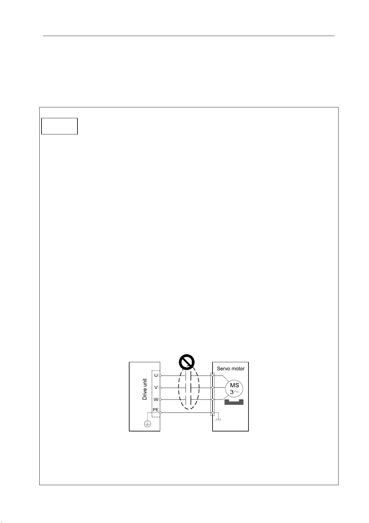
Page 6
Safety Warnings
Do not connect the power input wires R, S and
T to the output terminals U, V and W of the
motor.
Negligence of the instruction may
lead to equipment damage.
Do not touch the heat sink for the motor and
servo unit during operation as they may
become very hot.
Negligence of the instruction may
lead to burn.
Caution
Do not turn on/off the input power supply.
Negligence of the instruction may
lead to equipment damage.
Do not perform any limit adjustment or change
of parameters.
Negligence of the instruction may
lead to equipment damage.
Do not attempt to modify, remove or repair the
drive unit without permission from your dealer.
Negligence of the instruction may
lead to equipment damage.
The electronic components inside a discarded
drive unit shall be disposed as industrial waste
without reuse.
Negligence of the instruction may
cause accidents.
5
Page 7

DA98E Series AC Servo Drive Unit User Manual
Safety Responsibilities
Safety Responsibilities of Manufacturer
—— The manufacturer shall be responsible for the risks eliminated and/or controlled in
the design and structure of the supplied servo unit and accompanying accessories.
——The manufacturer shall ensure the safety of the supplied servo unit and
accompanying accessories.
——The manufacturer shall be held responsible for the information and advices on
usage given to the user.
Safety Responsibilities of User
——A user shall study and be trained for the safe operation of the servo unit and
understand and master the knowledge regarding safe operation.
——The user shall take responsibility for the risks arising from his/her addition, change
or modification of the original servo unit and accessories.
——The user shall be held responsible for the risks caused by the operations,
adjustments, installation and transport of the product without following the
requirements of the manual.
This manual is retained by the end user.
Thank you for your friendly support in using the products of GSK
CNC Equipment Co., Ltd.
6
Page 8

Contents
Contents
Chapter 1 Summary ........................................................................................................................................ 1
1.1 Product Overview................................................................................................................................1
1.2 Fundamentals...................................................................................................................................... 2
1.3 Receiving Inspection ..........................................................................................................................8
1.4 Product Appearance......................................................................................................................... 10
Chapter 2 Installation ...................................................................................................................................12
2.1 Ambient Conditions ........................................................................................................................... 12
2.2 Installation of Servo Drive Unit........................................................................................................ 12
2.3 Installation of Servomotor ................................................................................................................ 15
Chapter 3 Wiring............................................................................................................................................ 17
3.1 Standard Connection........................................................................................................................18
3.2 Functions of Terminals .....................................................................................................................21
3.3 Circuitous Philosophy of I/O Interface ...........................................................................................28
Chapter 4 Parameters................................................................................................................................... 29
4.1 Summary of Parameters.................................................................................................................. 29
4.2 Functions of Parameters.................................................................................................................. 32
4.3 Checklist of Model Numbers and Specification of Motor ............................................................42
Chapter 5 Alarms and Remedies............................................................................................................... 44
5.1 Abnormalities Arising from Improper Usage ................................................................................. 44
5.2 Summary of Alarms .......................................................................................................................... 45
5.3 Solutions for Alarms.......................................................................................................................... 47
Chapter 6 Display and Operations............................................................................................................58
6.1 Keyboard Operations ....................................................................................................................... 58
6.2 Monitoring Mode ...............................................................................................................................59
6.3 Parameter Setting ............................................................................................................................. 61
6.4 Parameter Management ..................................................................................................................63
6.5 Speed Trial operation ....................................................................................................................... 65
6.6 JOG operation ...................................................................................................................................66
6.7 Other ................................................................................................................................................... 66
VII
Page 9

DA98E Series AC Servo Drive Unit User Manual
Chapter 7 Power-on and Operation .......................................................................................................... 67
7.1 Connection to Power Supply ...........................................................................................................67
7.2 Trial Operation ...................................................................................................................................69
7.3 Adjustments........................................................................................................................................71
Chapter 8 Product Specification................................................................................................................75
8.1 Specification of Drive Unit................................................................................................................75
8.2 Specification of Servomotor.............................................................................................................76
8.3 Isolation Transformer........................................................................................................................85
Chapter 9 Ordering Guide ...........................................................................................................................91
9.1 Capacity Selection.............................................................................................................................91
9.2 Electronic Gear Ratio........................................................................................................................91
9.3 Stop Characteristics..........................................................................................................................92
9.4 Calculation for Type Selection of Servo and Position Controller................................................92
9.5 Examples of Model Numbers Available for Ordering ...................................................................93
VIII
Page 10

Chapter 1 Summary
Chapter 1 Summary
1.1 Product Overview
The AC servo technology has been proved since the early 1990s. With ever-improving
performance, it is widely applied to NC machine tools, printing and packaging machines, textile
machines, automated production lines and other areas of automation.
DA98E series AC servo Drive Unit (also known as bus-oriented AC servo Drive Unit) is a
new generation of products with an up-to-date industrial Ethernet bus communication
interface developed by us.
The external control device for the series of Unit can communicate with several GSK-LINK
bus-oriented AC servo Drive Unit through only one network cable. They feature simple interfaces,
easy installation and high compatibility. Through a high-speed and reliable GSK-LINK field bus and
protocol, a NC system may receive/send diversified data including position, speed command, motor
encoder data, controlling parameters for current loop, speed loop and position loop, state parameters
of drive unit and other messages from/to a servo Drive Unit. By supporting diversified data, the
system may exert control over the operation of a motor and better realize the real-time monitoring of
the control and drive Unit through configuration of position, speed command and adaptive
parameters of the system, thereby further improving the processing efficiency and accuracy of the NC
system. With a built-in advanced and dedicated chip for control over the motor, a FPGA
(Field-Programmable Gate Array) and a new IPM intelligent power module, the servo drive unit is
characterized by high integrity, compactness, complete protection and high reliability.
DA98E AC servo unit has the following advantages over step drive Unit:
z No out-of-step
The servomotor is provided with an encoder that
feeds back position signal to the servo drive unit
and exerts semi-closed loop control with an
open-loop control device.
z Wide speed ratio and constant torque
Open-loop control Stepper motor
Speed regulation ratio of 1: 5000 and constant
torque characteristics at low to high speed;
z Incremental encoders or Tamagawa 17-bit
absolute encoders are available upon customer’s request.
z High speed and accuracy
Maximum rotating speed of servomotor: 3,000 rpm; rotary positioning accuracy: 1/10,000r
Note: The maximum rotating speed of servomotor varies with its model.
Controller
1
Page 11

DA98E Series AC Servo Drive Unit User Manual
z Simple and flexible control
It is possible to properly set the operating mode and characteristics of the servo system through
the system interface in order to meet different requirements.
DA98E compared to the traditional DA98 servo series
z The data transfer speed is up to 100MBit/s by using an industrial Ethernet bus for
communication transmission.
z High anti-jamming capacity, bit error rate: 10
-12
z The closed and open loops share one hardware structure with a communication data
length of 0~256 (bits) and minimum communication cycle of 50µs.
z It is easy to operate and adjust servo parameters and possible to adjust servo parameters
and monitor servo through the system interface.
1.2 Fundamentals
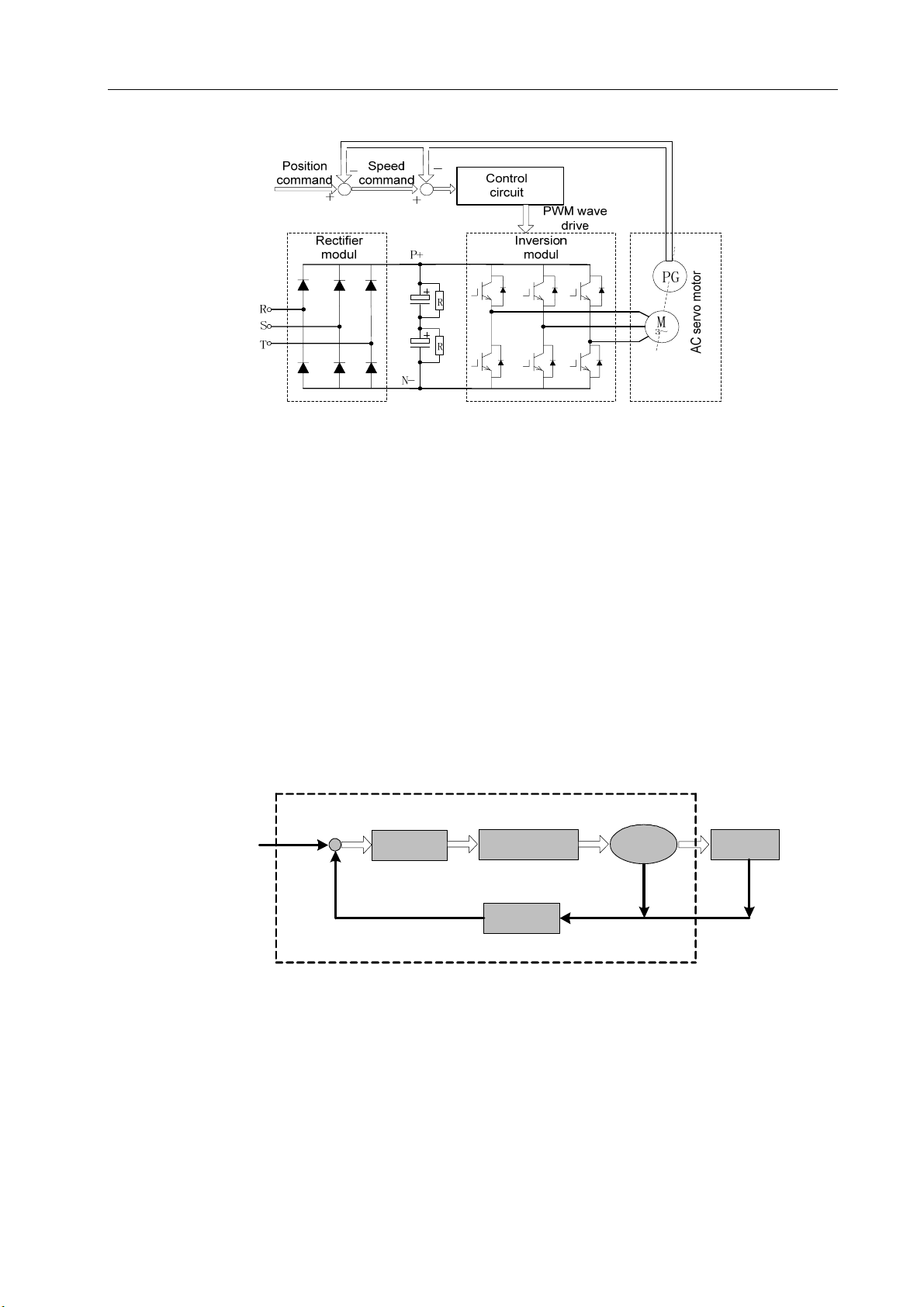
1) Operating Principle of AC Servo Drive Unit
The AC servo drive unit consists of an AC servo unit and an AC servomotor (3-phase
permanent-magnet synchronous motor, hereinafter called “servomotor”). The servo unit rectifies
3-phase alternating current into direct current (namely AC to DC) and produces approximately simple
harmonic alternating current with 120° phase difference in the 3-phase stator winding of the
servomotor by controlling the switching of the power switching tube. The current creates a rotating
field in the servomotor. The rotor of the servomotor is made of high anti-demagnetizing rare-earth
permanent magnetic material. The rotor of the servomotor is driven by the electromagnet torque as a
result of the interaction of the magnetic field of the rotor for the servomotor and its rotating magnetic
field. The higher the frequency of the current through the servomotor winding is, the faster the
servomotor rotates. The output torque (torque = force x length of moment arm) of the servomotor
increases with the amplitude of the current through the servomotor winding.
Figure 1-1 is the block diagram of the main circuit in which PG indicates an encoder.
2
Page 12
Chapter 1 Summary
Figure 1-1 Block diagram of the main circuit of AC servo drive unit
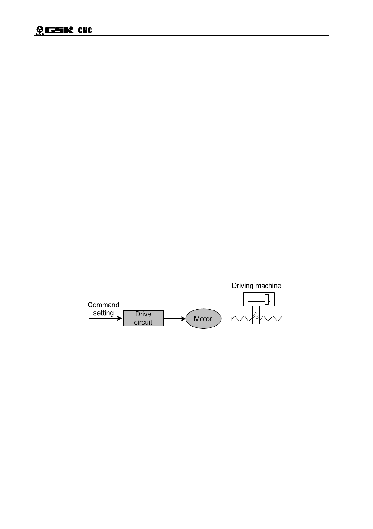
2) Basic Structure of AC Servo Drive Unit
The servo unit receives speed commands from a control unit (also known as host computer)
such as CNC system to control the amplitude and frequency of the current through the winding of the
servomotor so that the rotating speed (or angle of rotation) of the rotor for the servomotor is close to
the value of the speed (or position) commands, and knows the deviation of the real rotating speed (or
angle of rotation) of the servomotor rotor from the command value through the feedback signal of the
encoder. The servo unit keeps the deviation of the real rotating speed (or angle of rotation) of the
servomotor rotor from the command value within the required range by continuous regulating the
amplitude and frequency of the current through the winding of the servomotor. The basic structure of
the servo system is shown in Figure 1-2.
setting
CNC
equipment
+
-
AC servo drive equipment
Control
unit
Power drive unit
Feedback
check
Motor
Driving
machine
Figure 1-2 Basic structure of AC servo drive unit
3) General Glossaries regarding Control
z Control: Control refers to the procedure allowing the characteristics (e.g. rotating speed) of the
object (e.g. servomotor) to reach or become close to the expected value. The foregoing object is
called “controlled object”, its characteristics “controlled variable”, the device that realizes the control
“control unit (controller)”, the expected value (command value) of the controlled variable received by
3
Page 13
DA98E Series AC Servo Drive Unit User Manual
the control unit “setting”, the process that the controlled variable is affected as the input of the
controller “feedback” and the unit that is used to detect the controlled variable “feedback unit”.
Feedback is divided into positive feedback (in the same direction) and negative feedback (in opposite
direction). The controller that realizes the controlled variable, the controlled object and feedback unit
compose a “control system”. A drive is under closed-loop control or open-loop control depending on
the presence of a feedback unit and the position where the feedback unit is located in the drive. The
closed-loop control described in the manual is of negative feedback.
Among the AC servo Drive Unit described herein, the servo unit serves as a controller, the
servomotor controlled object, rotating speed (or angle of rotation of rotor) of motor controlled variable
and the encoder of the servomotor feedback unit. The encoder detects the actual rotating speed of
the motor for speed control so as to achieve speed feedback. Therefore the AC servo drive unit is a
closed-loop control system.
z Closed-loop control: The actual value of the controlled variable does not affect the output of the
controller if the control system is not provided with a feedback device. For a stepper motor drive, for
example, the rotor of a stepper motor shall rotate with the change in the phase sequence of its output
current. Since normally a stepper motor is not fitted with a speed or position feedback device,
excessive load or acceleration/deceleration may prevent the motor rotor from accurately rotation with
the change in the phase sequence of current, thereby causing the so-called “out-of-step”.
Open-loop control is as shown in Figure 1-3.
Figure 1-3 Open-loop control
z Closed-loop control: The controlled variable of the control system is detected and transferred to
the controller by the feedback device to affect the output of the controller and thereby to change the
controlled variable. Closed-loop control is classified as full-closed loop control and semi-closed
loop control by the detection points. The feedback device’s direct detection of the controlled variable
and use of it for feedback is called full-closed loop control (e.g. Figure 1-4) and the position of the
gear is the controlled variable. The full-closed loop control over the position of the gearing is achieved
by using the grating mounted on the gearing as a position feedback device and the encoder for the
Gearing
servomotor as a speed feedback. In the absence of the grating, the encoder for the servomotor is
used as a position and speed feedback (see Figure 1-5). In this case, this is the semi-closed control
over a mechanical position.
4
Page 14

Figure 1-4 Full-closed loop control
Chapter 1 Summary
Figure 1-5 Semi-closed loop control
z PID Control: Also called PID regulation, it is the common algorithm used by the controller
for mathematical treatment of the input data (setting and feedback). “P” is the abbreviation of
“proportional” and refers to the linear proportional relationship between the input and output of a
controller. The bigger a proportional control factor is, the more sensitively the system will respond and
the smaller (cannot be completely eliminated) the steady state error will become. Excessive
proportional control factor leads to the disturbance and instability of the system. “I” stands for
“integral” and means the influence of controller input time integral upon output (input gradually affects
output). The bigger an integral time constant is, the more smoothly the system runs without steady
state error and the slower the system responds. “D” is the initial of “Differential”, indicating the
influence of input differential (the slope of input change). Differential control can forecast, produces
advanced correction, reduces following error and improves dynamic performance. Excessive
differential coefficient may cause system disturbance and instability. Proportional, integral and
differential controls influence each other. In a specific control system it is required achieve the
balance of the response speed, control accuracy and stability by adjusting the PID control parameters.
As differential control tends to produce impact and unsteadiness, the servo system described herein
employs PI control, i.e. only proportional and integral control.
5
Page 15
DA98E Series AC Servo Drive Unit User Manual
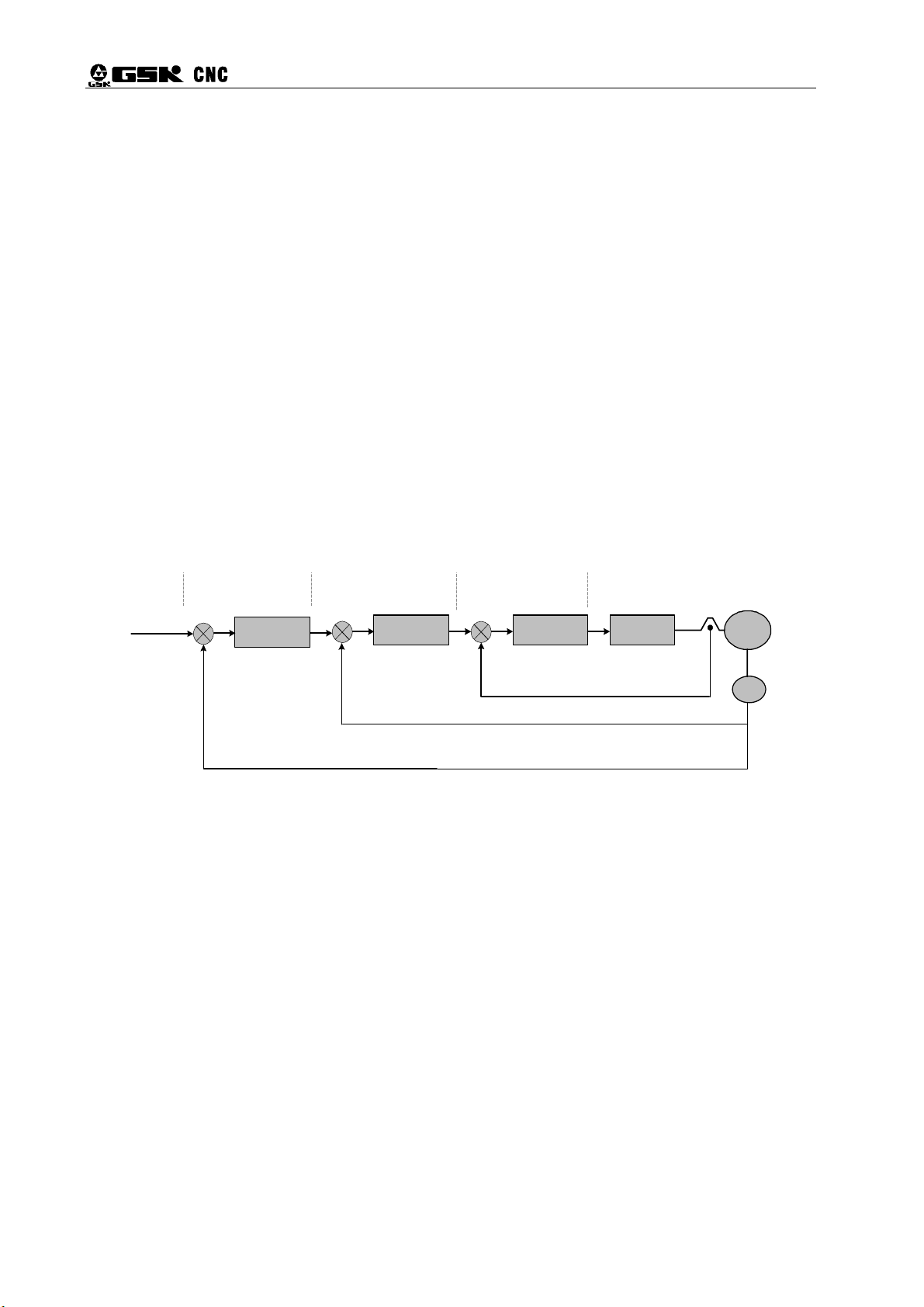
4) Glossaries with regard to Servo Control
The servo system is provided with three basic control modes: position control, speed control and
torque control. The block diagram of the system is as shown in Figure 1-6.
z Position control: The direction and angle of rotation of the motor are set by means of digital
pulse or data communication. The servo unit controls the motor rotor so that it rotates by a proper
angle in the given direction. Both the angle (position) and speed of rotation are controllable.
z Speed control: The direction and angle of rotation of the motor are set by means of analog
voltage or data communication. The servo unit controls the motor rotor so that it rotates in the given
direction at the given speed.
z Torque control: The amplitude and direction of the output torque of the motor are set by
means of analog voltage or data communication. The servo unit controls the direction of rotation and
output torque of the motor rotor.
The servo unit described herein currently does not receive any torque setting signal or provide
torque controlling mode.
+
Command
position
Position
controller
Position
adjustment
-
Position
feedback signal
Speed
controller
+ Speed
adjustment
-
Speed feedback
signal
+
Current
controller
Current
adjustment
-
Current feedback
signal
Power
amplification
Motor
PG
Figure 1-6 Block diagram of three-loop control
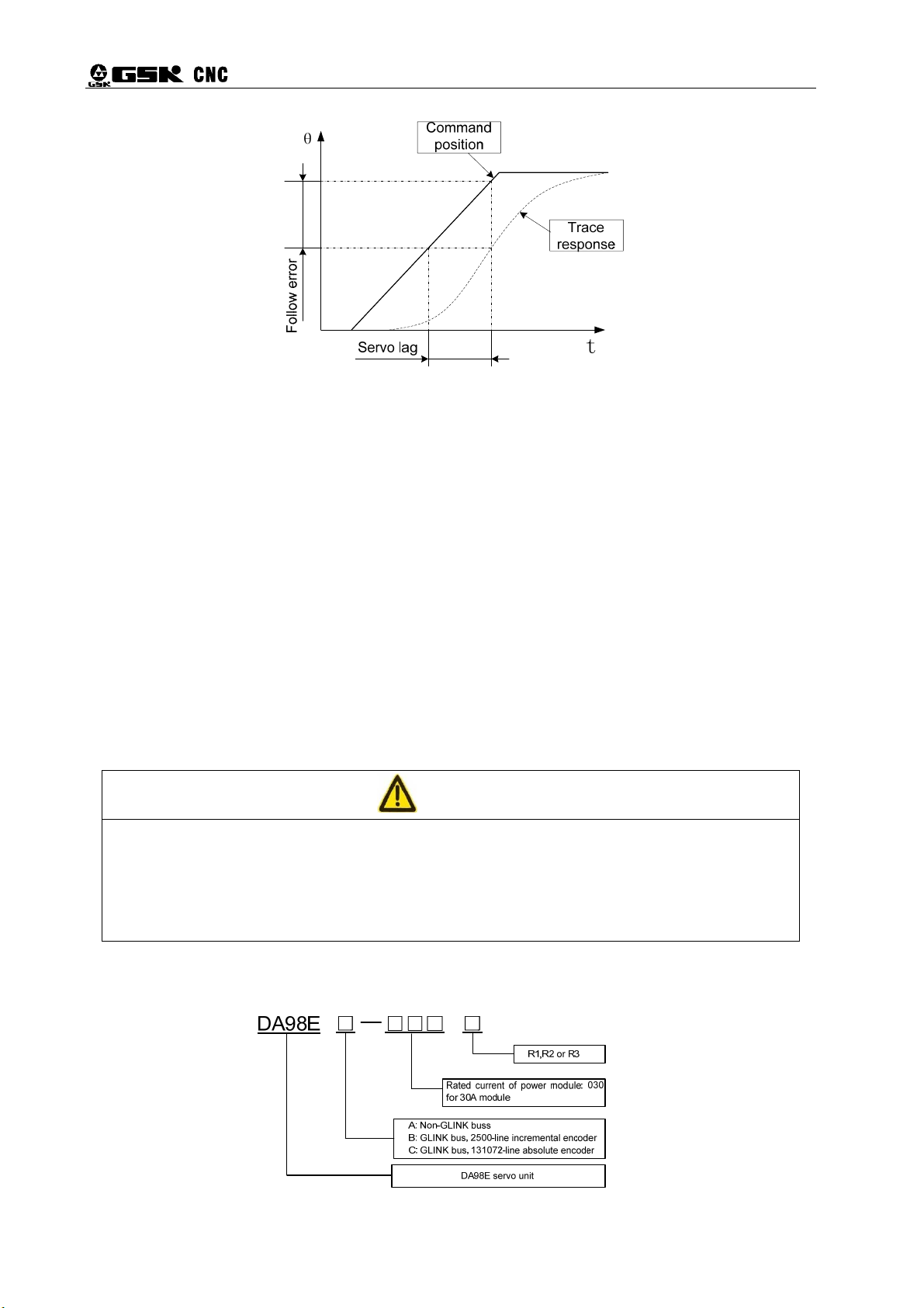
5) Indexes of Servo Performance
Characteristics of servo dynamic response: the response speed, dynamic control error and
steady-state control error. Figure 1-7 is the response characteristic diagram of the given step signal
from the servo signal (The solid line indicates given signal and dotted line the output signal from the
servo system in the following text.):
6
Page 16
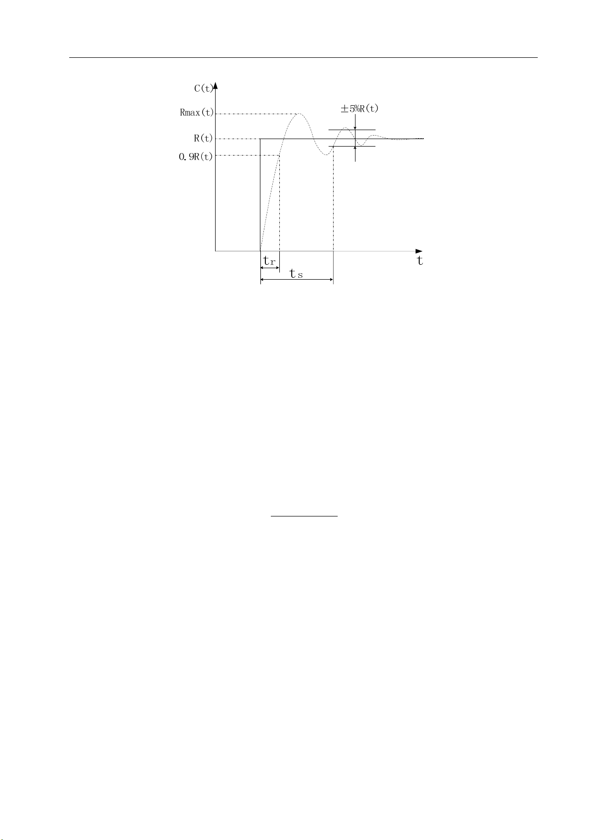
Figure 1-7 Servo dynamic response curve
Chapter 1 Summary
Rise time t
of steady state value R (t). It indicates the rapidity of dynamic response.
Adjustment time t
value of the step response curve is considered a permissible error band. The minimum time required
for the response curve to reach but not go beyond the error band is the adjustment time which is used
to measure the rapidity of the complete adjustment process of the unit.
Overshoot σ: It refers to the ratio of the maximum rotating speed difference (Rmax(t)-R (t)) between
rotating speed output and steady-state value to steady-state value R (t). It reflects the relative stability
of a servo unit and is as follows when indicated by percentage:
Steady-state error: The difference between the expected steady-state value and actual output of the
system after rotating speed becomes steady during system response.
Servo static performance: The most important for a servo control system is its stability. The key
: It refers to the time elapsed when the rotating speed output rises from zero to 90 percent
r
: The range within ±5% of the steady-state value taken near the steady-state
s
)()(
−
σ
(%)
max
=
tRtR
)(
tR
%100
×
static performance index of servo is positioning accuracy, which refers to the degree of deviation of
the actual state from expectation at the end of the system transition. The steady-state accuracy of
servo is subject to the error of position measuring appliance and system error and is related to the
structure and parameters of the system. Figure 1-8 is a position servo static curve graph.
7
Page 17
DA98E Series AC Servo Drive Unit User Manual
Figure 1-8 Position servo static curve
Following error: It refers to the difference between the displacement of workbench required by
command signal (command position) and its actual displacement. That is to say, Following error =
(Command position value) – (Actual position value)
Servo gain: It refers to the capability of a servo system’s resistance against the position deviation
resulting from load interference.
1.3 Receiving Inspection
1) When the goods is received, make sure to inspect the following items:
(1) Check that the packing case is integrate and no cargo is damaged in transport;
(2) Check that the received goods are those ordered against the nameplates on the
servo drive unit and servomotor;
(3) Check that the accessories are complete against the packing list.
Attentions
z Do not install a defective or incomplete servo unit;
z The servo drive unit shall be used in combination with a servomotor with matching
performance;
z Please contact your dealer or us for any question when the goods are received.
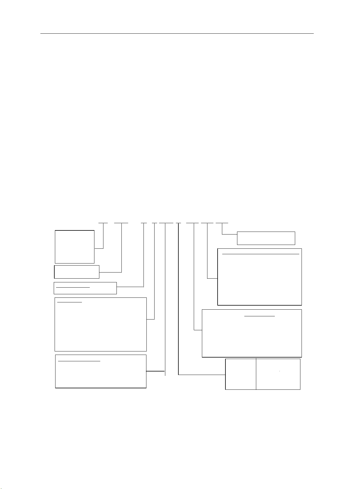
2) Description of Model Number
(1) Model Number of Servo Drive Unit
8
Page 18
Chapter 1 Summary
Note: Type R1 is a thin radiator, R2 thick radiator and R3 a thick radiator with a fan.
Note 1: Optional imported or home-made servomotor is available upon request. The default parameters of the
drive unit are only adaptive to SJT and ST series of servomotors. For other servomotors, the delivery
parameters are backed up in EEPROM. To recover the delivery parameters, make sure to perform recovery
backup but not to restore default parameters.
Note 2: Use standard configuration for middle or low power (≤1.5kW) and thick radiator for the power above middle
level (> 1.5kW).
Note 3: The above boxes have been completed before product delivery. Please check them against the nameplate of
the product.
(2) Model Number of Servomotor
The DA98E series of bus-oriented AC servo drive Unit may be used in conjunction with many foreign
and domestic servomotors that can be selected by user in ordering. The Chapter 8 of this manual
offers the information on the SJT series of GSK and the new ST series of servomotors made by New
Type Motor Factory affiliated with Huazhong University of Science and Technology. The information
on other types of servomotors is supplied with them.
130 SJT
Machine model:
80
110
130
175
AC synchronous
servo motor
Feedback unit:
M:Photoelectric encoder
Safe brake
None : None ; Z: Available
Remark: The working power supply of safe brake
is DC(0.9~ 1.1)×24V, the interface is 3-cord
socket, pin 1 and pin 2 are power supply terminal
(not differ polarity), pin 3 is earth terminal. When
pin 1 and pin 2 i s connecte d the power supply,
the sa fe brake doesn’t work; when the power is
OFF, it works. The brake operation time is ≤0.1s.
Zero-speed torque
Remark: It is represented by three
digits, and the value is in three digits
-1
,the unit is N ·m.
×10
For example, 150×10
Note 1: The working power supply for the dead electromagnet brake is DC (0.9~1.1) ×24V and its connector a
-1
=15N·m.
MZ150 D(A□Y□X
-
□
)
None:Aviation socket type
X:Cable direct type
Shaft extenstion or installation config.
None:Standard shaft extension
Y□:Special cylinder shaft extension
Z□:Special cone shaft extension
S□:Stepping motor installation config.
Remark: In the blank“□”, it is digit code;
about the number representing the detailed
special axis extension, refer to the
installation overall drawing of the motor.
Encoder type
A or None:
A2:Increment type 5000 p/r
A3:Increment split-type 2500 p/r
A4:Absolute type 17bit
A41:Danaher multi-circle 17bit absolute type
A4S1:Danaher single-circle 17bit absolute type
Rated speed
Increment type 2500 p/r
1000 r/min
A
:
1500 r/min
B
:
2000 r/min
C
:
2500 r/min
D
:
E
:
3000 r/min
3-pin socket whose Pin 1 and 2 are power inputs (not polarity specific) and Pin 3 is a ground terminal. When
Pin 1 and 2 are connected to power supply, the dead electromagnet brake does not function. When they are
disconnected from power supply, it operates for a duration less than or equal to 0.1s.
-1
Note 2: “150” indicates that its value consists of three digits 150×10
=15 in N·m.
9
Page 19
DA98E Series AC Servo Drive Unit User Manual
Note 3: ‘□’ is a numeral code. See the installation diagram of the motor for the specific special shaft extension
indicated by a figure.
3) Accessories
(1) Standard accessories for DA98E servo drive unit
① User Manual (this manual) 1
② Mounting bracket 2
③ M4×8 countersunk head screws 4
④ BUS1 plug (DB9 jack), BUS2 plug (DB9 pin) 1 set (Note 1)
⑤ CN1 plug (DB26 jack) 1 set (Note 2)
⑥
The standard accessories of a servo motor will be supplied to its operation manual.
Note 1: Our Ethernet bus communication position control device is supplied with a CAT-5e UTP signal cable (standard
length: 3m).
Note 2: A feedback cable (standard length: 3m) is available with our servomotor upon user’s request.
Note 3: The encoder feedback connector CN1 with an absolute encoder is a MDR26 plug.
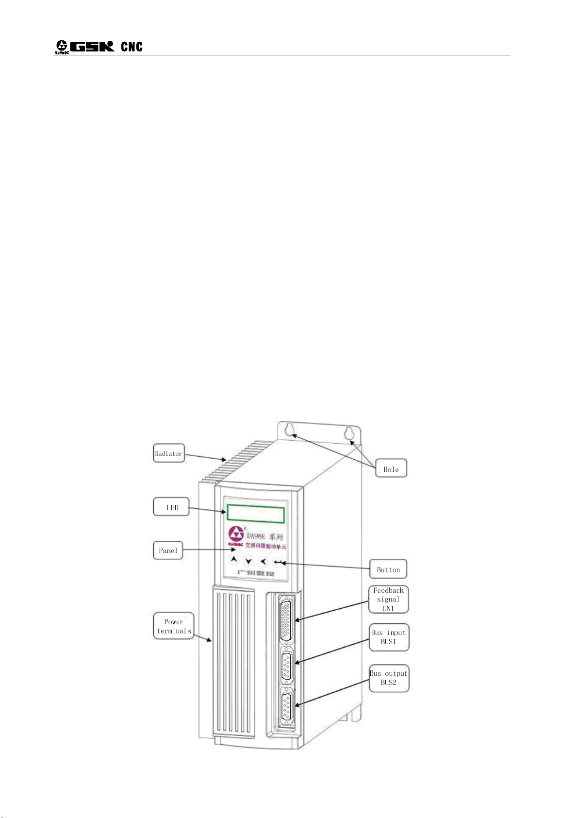
1.4 Product Appearance
1) Appearance of Servo Drive Unit
10
Page 20
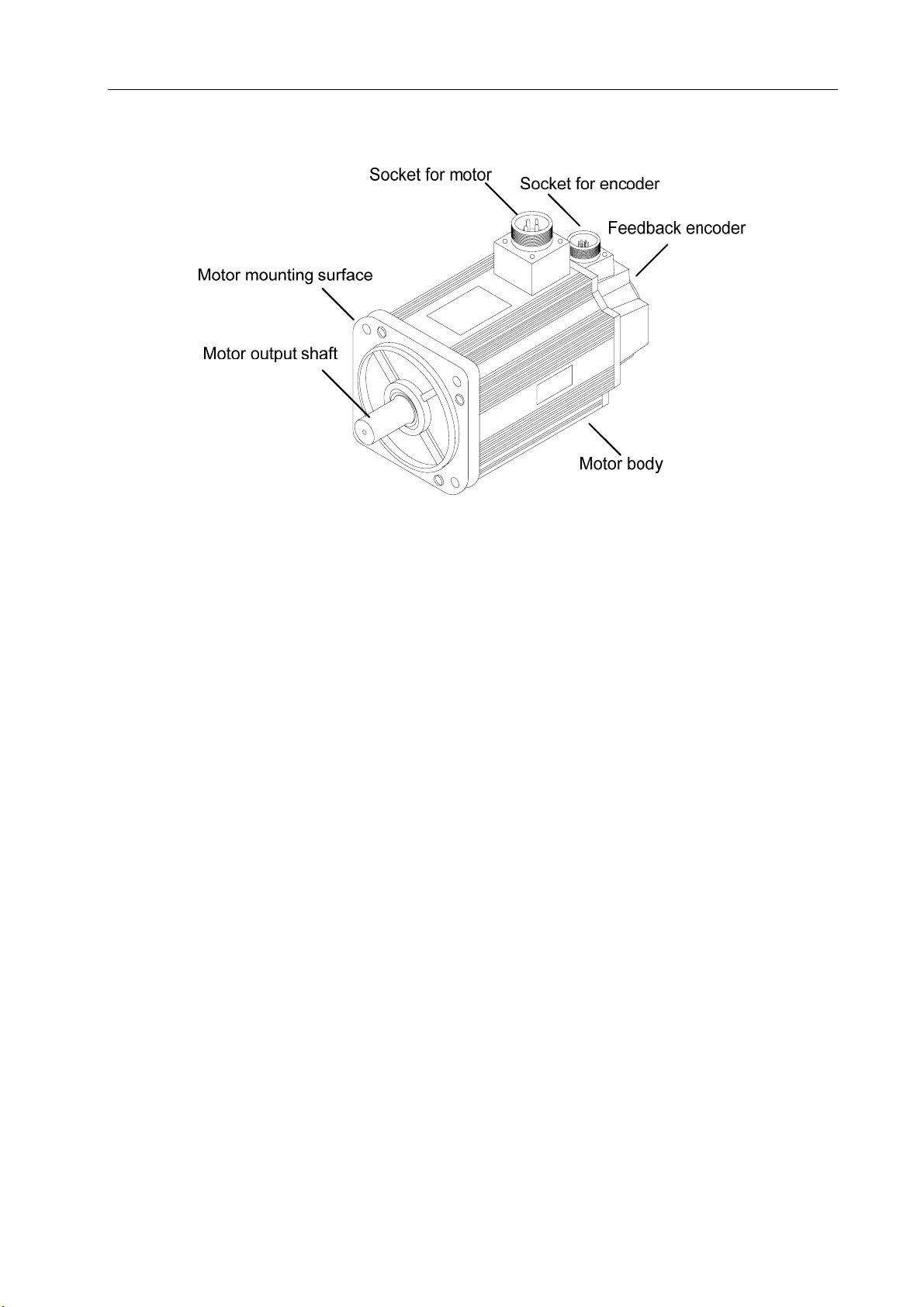
2) Appearance of Servomotor
Chapter 1 Summary
11
Page 21
DA98E Series AC Servo Drive Unit User Manual
Chapter 2 Installation
Attention
z The product shall be stored and installed in an environment meeting the requirements of the
specification.
z Do not stack up too many products as they are subject to damage under pressure and falling
down.
z The original package must be used for the storage and transport of the product.
z A damaged or incomplete product must not be installed and used.
z Always use fire-proof material for the installation of the product. Do not install it on or near
combustible materials to prevent fire.
z The servo drive unit must be installed in an electric cabinet in order to prevent dust, corrosive gas,
conductive substances and combustible matters from entering.
z The servo drive unit and servomotor shall be protected from vibration and impact.
z Never pull the motor cable, shaft and encoder.
2.1 Ambient Conditions
Item
Operating temp/humidity
Storage and transport
temp/humidity
Atmospheric
environment
Elevation Altitude below 2000m Altitude below 2000m
Vibration
Level of protection IP20 IP54
DA98E series of servo drive
Unit
0℃~40℃ (nonfreezing)
RH<90% (noncondensing)
-20℃~70℃
90%RH (noncondensing)
In a control cabinet without
corrosive or combustible gas, oil
mist, dust, etc.
< 0.5G(4.9m/s2)10 H
GSK SJT series of servomotors
-10℃~40℃ (nonfreezing)
RH<90% (noncondensing)
-40℃~70℃
RH<85% (noncondensing)
Indoors (without direct sunlight) without
corrosive or combustible gas, oil mist,
~60HZ (discontinuous operation)
Z
dust, etc.
2.2 Installation of Servo Drive Unit
Attention
z The servo drive unit must be installed in an electric cabinet properly protected (≥IP43).
z The servo drive unit must be installed in the direction with spacing as specified and provided with
good heat eliminating condition.
z It must not be installed on or near combustible materials to prevent fire.
12
Page 22
Chapter 2 Installation
1) Installation Environment
(1) Protection
Since the structure of the servo drive unit is of IP 20, it must be installed in an electric cabinet
(≥IP43) properly protected and protected from exposure to corrosive and combustible gas and entry
of conductive matters, metallic dust, oil dust and liquid.
2) Temperature/humidity
Ambient temperature: 0℃~50℃. For extended safe operation, the unit shall be installed in an
environment at altitude less than 2000m and temperature below 40℃ and protected with good
ventilation conditions.
(1) Vibration and Impact
The drive unit shall be protected from vibration. Measures shall be taken to control vibration
under 0.5(4.9m/s
2
) as the drive unit cannot bear any high pressure or impact.
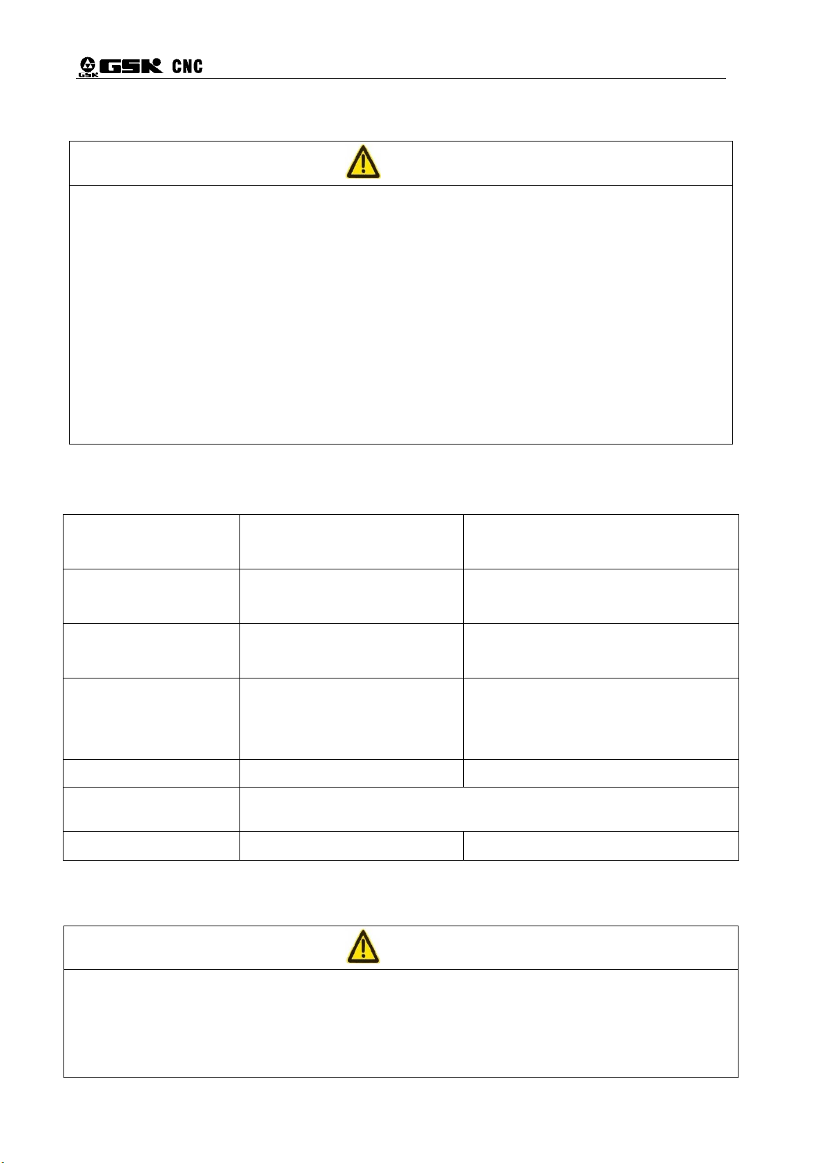
3) Installation Procedure
(1) Installation Means
The user may install the unit by means of base or face plate in a direction perpendicular to the
mounting surface. See Figure 2-1 for the diagram of base-plate mounting and Figure 2-2 face-plate
mounting.
Figure 2-1 Base-plate mounting of drive unit
13
Page 23
DA98E Series AC Servo Drive Unit User Manual
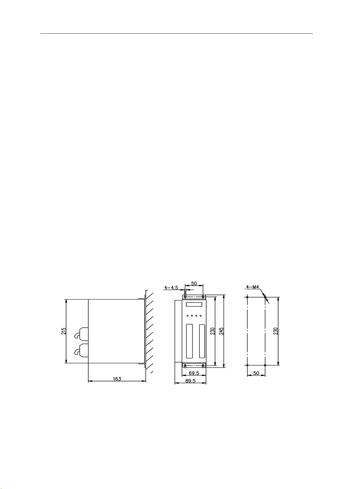
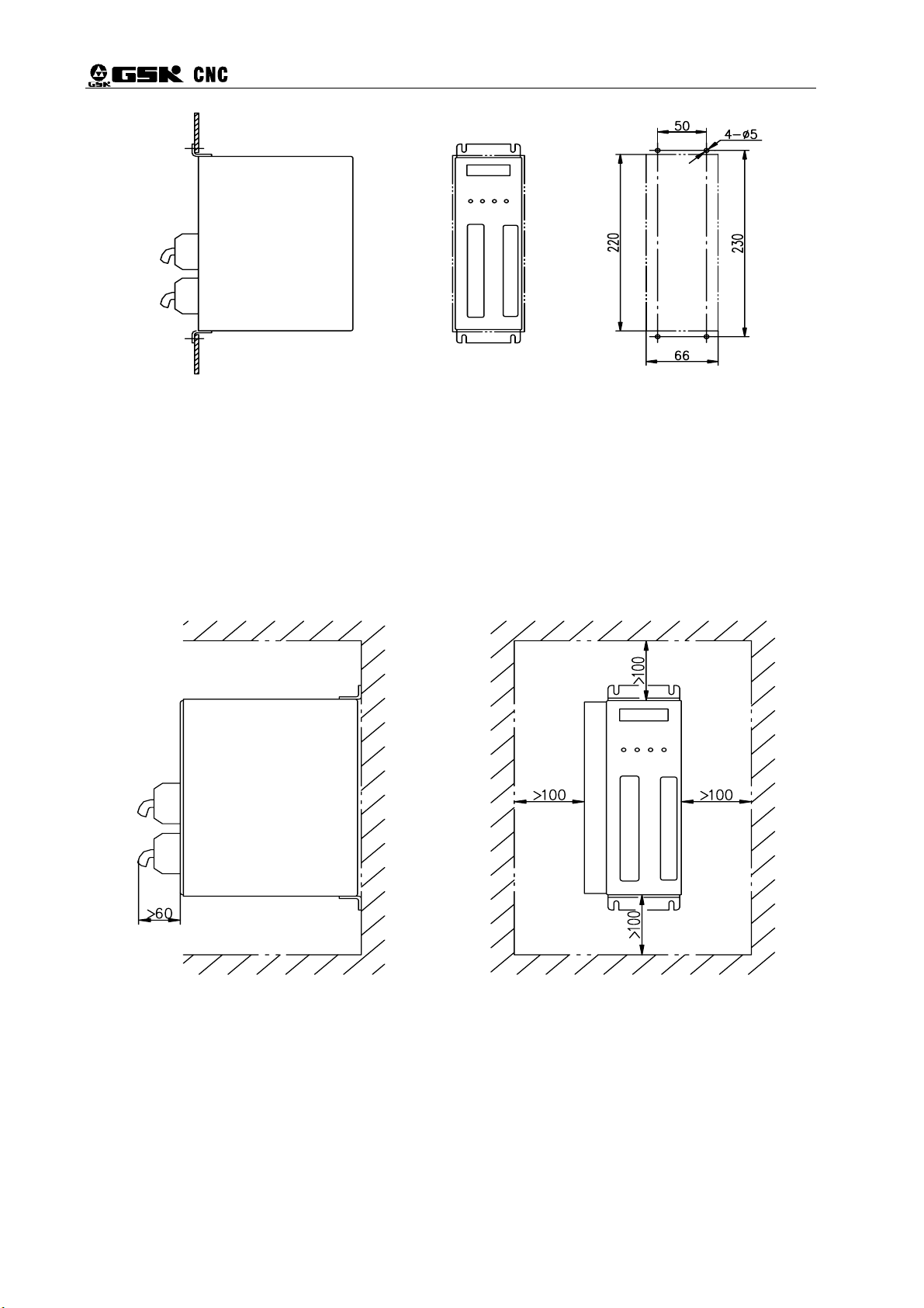
(2) Installation Space
Figure 2-3 shows the installation space for a single drive unit and Figure 2-4 the spacing
Figure 2-2 Face-plate mounting of drive unit
between several drive Unit. In actual installation, a space as big as possible shall be kept to
ensure good heat ventilation.
14
Figure 2-3 Installation space for single drive unit
Page 24
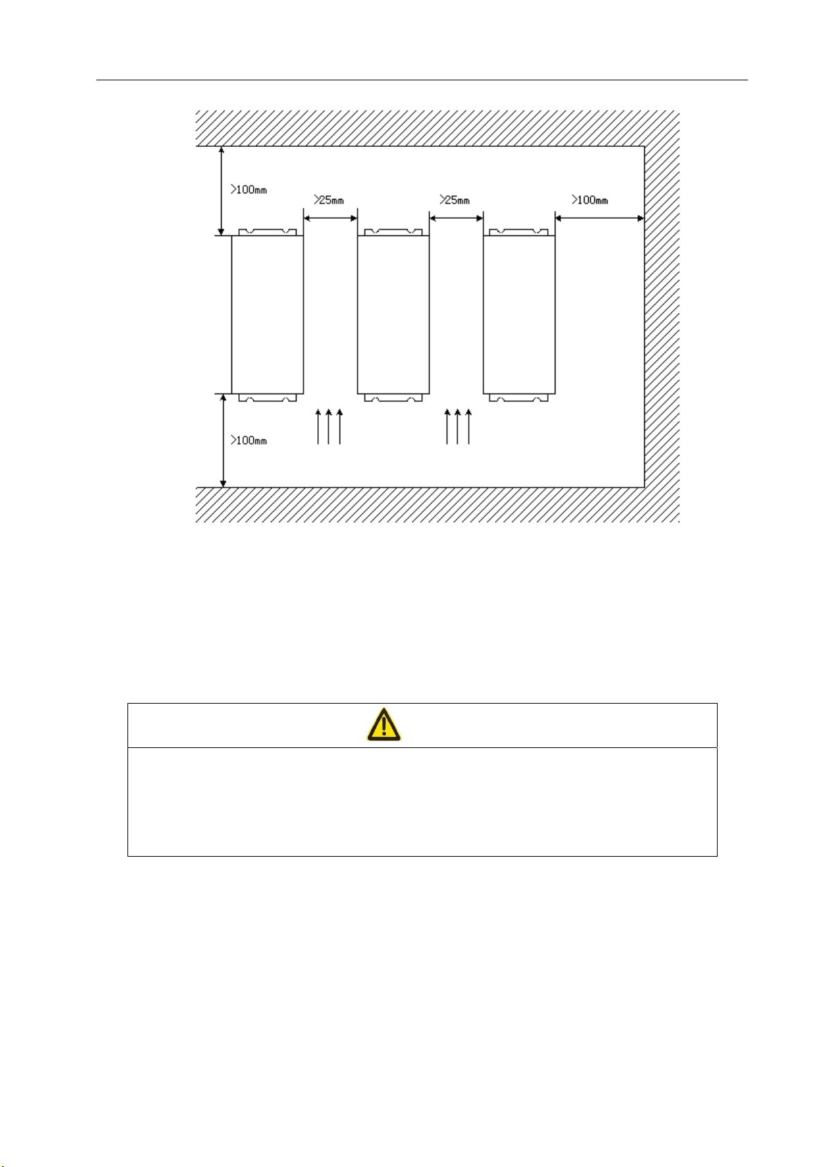
Chapter 2 Installation
Servo
driver
Figure 2-4 Installation spacing between several drive Unit
(3) Heat Elimination
To prevent ambient temperature of the drive Unit from rising, radiators shall be fitted in the
electric cabinet to blow convection air to the Drive Unit.
Servo
driver
Servo
driver
Direction of ventilation Direction of ventilation
2.3 Installation of Servomotor
Attention
z Never knock the motor shaft or encoder. Protect the motor from vibration or impact.
z For handling of the motor, do not pull its shaft, outgoing wires or encoder.
z The motor shaft shall be protected from overloading as this may cause damage to it.
z The motor must be installed securely and protected from becoming loose.
1) Installation Environment
(1) Protection
In consideration of that currently GSK SJT series and Huazhong ST series of servomotors are
not waterproof, the motors must be kept away from liquid and oil or water prevented from entering the
motors along the outgoing wires and motor shaft.
Note: Please specify in ordering of a waterproof servomotor.
15
Page 25

DA98E Series AC Servo Drive Unit User Manual
(2) Temperature/humidity
The ambient temperature of the motor shall be kept between -10℃ and 40℃. A forced heat
eliminating means shall be considered when its surrounding space is limited or when there is a
heating device nearby.
The ambient humidity shall be above 90% RH (noncondensing).
(3) Vibration
The servomotor shall not in a location with vibration over 0.5G (4.9m/s
2
).
2) Installation Procedure
(1) Installation Means
At present the SJT and ST series of motors are installed in any direction by means of flange.
(2) Precautions for Installation:
z While removing the pulley, do not know the motor or its shaft as this may cause damage to
the encoder. Remove or fit it with a spiral pressing and pulling tool.
z Currently most of the SJT and ST series of motors cannot bear high axial and radial loads. It
is recommended to connect a load with flexible coupling.
z Use lock washers to prevent the motor from becoming loose while fixing the motor.
Note: Refer to Chapter 8 for the specification and installation dimensions of the servomotor.
16
Page 26
Chapter 3 Wiring
Chapter 3 Wiring
Carefully read and strictly abide by the following precautions which ensure your operating safety
and reliability.
The wiring shall be properly carried out by a well-trained and qualified technician by
Attention
following the associated instruction.
Any wiring or repair work on the servo unit can be performed only when you make
sure the voltage-to-ground on all the terminals of the main circuit are safe five
minutes after it is disconnected from the servo unit. Otherwise it may cause an
electric shock.
Make sure the servo unit and servomotor are correctly grounded.
For wiring, do not damage the cable with a sharp object or forcibly pull it as it may
lead to electric shock or poor line contact.
Never extend connecting cables for the main circuit and signal cables through the
same conduct or bind them together. In wiring, the connecting cables for the main
circuit and signal cables shall be routed separately or crosswise with spacing over
30cm in order to prevent heavy-current lines from interfering the signal cables and
causing the malfunction of the servo unit.
Do not frequently turn on/off the power supply as the built-in high-capacity
capacitors in the servo unit generates high charging current during powering on and
frequent switching of the power supply may deteriorate the performance the
components in the servo unit. A switching interval of 3min or longer is advised.
Do not fit any additional power capacitor, surge arrester, wireless noise filter and
other devices between the servo unit output side and servomotor.
The wiring of the main circuit and signal cables shall be kept away from heat sink
and electric motor in order to prevent their insulating property from deterioration by
heating.
After the wiring of the main circuit, attach the terminal cover to avoid electric shock.
17
Page 27

DA98E Series AC Servo Drive Unit User Manual
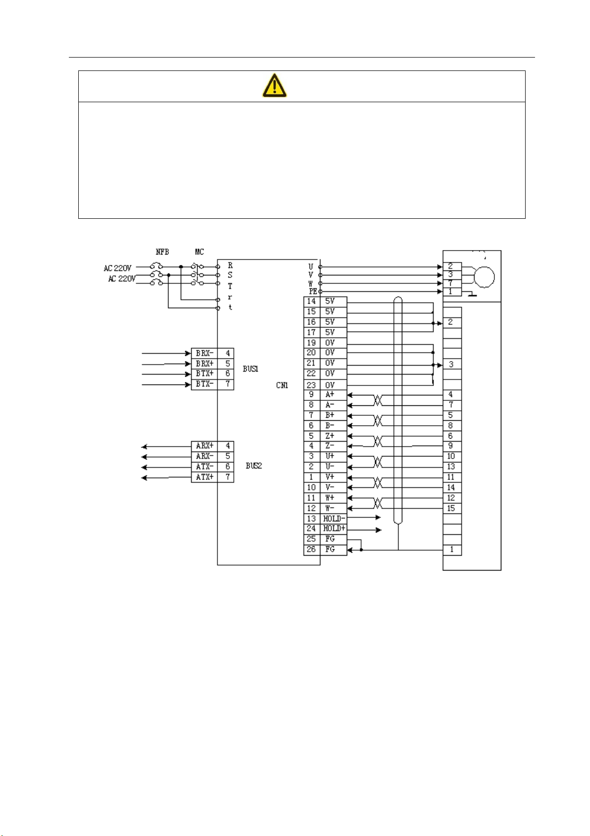
3.1 Standard Connection
The external connection of the drive unit depends on its control mode.
1) Position control mode:
Figure 3-1 shows the standard connection for the position control mode.
2) Speed control mode:
Figure 3-1 shows the standard connection for the speed control mode.
3) Wiring
(1) TB Power Terminals
2
z Wire sizes: Diameters of the wires to terminals R, S, T, PE, U, V and W ≥1.5mm
and those of terminals r and t ≥1.0 mm
2
(AWG16-18)
z Grounding: The ground wire shall be big and short as much as possible and the drive unit and
(AWG14-16),
servomotor share the PE terminal.
z JUT-1.5-4 pre-insulated cold-pressed terminals are used for terminal connection. Always
connect them securely.
z It is recommended to supply power to the unit using a three-phase insulating transformer to
minimize the potential of electric shock.
z It is recommended to supply power through a noise filter in order to improve the anti-jamming
capacity of the unit.
z Install non-fusible (NFB) breaker so that the external power supply can be duly disconnected
in the event of drive unit fault.
(2) Control Signals BUS1 and BUS2 and Feedback Signal CN1
z CAT-5e UTP engineering cables are used control signal cables;
z Sizes of the feedback signal wires: A shielded cable (it is advisable to use a twisted shielded
cable) whose wire diameter shall not be less than 0.12mm2(AWG24-26) and shielding layer shall be
connected to the Terminal FG.
z Cable length: The power cord shall be as short as possible and the length of the feedback
signal CN1 cable must not be longer than 30m.
z Wiring: The wires shall be routed away from power lines to prevent cross-interference.
z Fit a surge arresting element for the inductive components (coils). Connect DC coils and a
freewheel diode in parallel reversely. Connect AC coils and resistance-capacitance absorbing circuit
in parallel.
18
Page 28
z Connect U, V and W to motor windings correspondingly. Never connect them reversely.
z Tighten the cables and conductors and keep them away from the drive unit radiator and
motor in order to prevent their insulating property from deterioration by heating.
z The high-capacity electrolytic capacitors in the servo drive unit maintain high voltage
(residual voltage) immediately after power-off. Do not touch the drive unit and the motor
within five minutes after power-off.
Three-phase or
single-phase
Chapter 3 Wiring
Attention
Electric motor
Servo
driver
Encoder
Figure 3-1 Standard wiring for position and speed control modes when an incremental encoder is
provided
19
Page 29

Three-phase or
g
p
sin
le-
hase
DA98E Series AC Servo Drive Unit User Manual
Electric motor
Servo driver
Absolute encoder
Figure 3-2 Standard wiring for position and speed control modes when a Tamagawa absolute
encoder is provided
20
Page 30
Chapter 3 Wiring
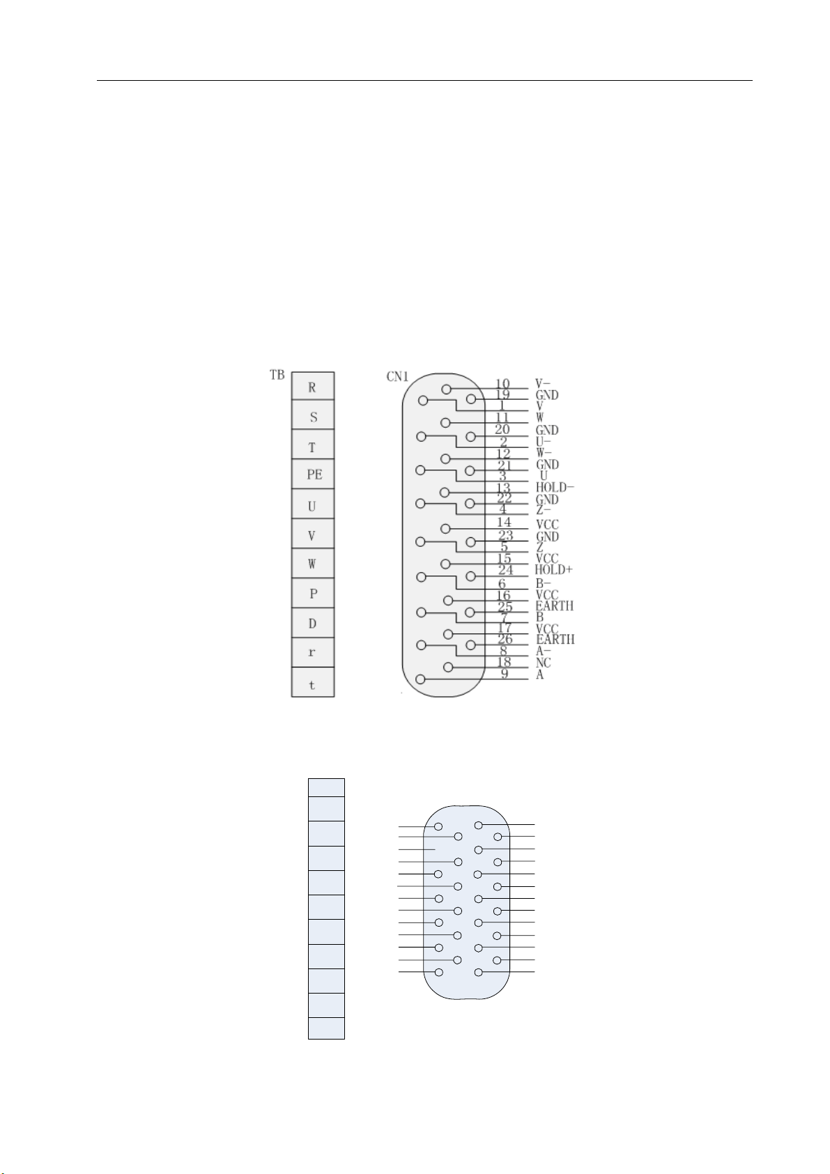
3.2 Functions of Terminals
(1)Terminal Configuration
Figure 3-3 is the diagram of configuring the terminals on the servo drive unit and incremental
encoder type motor. In the diagram TB is a terminal block and BUS1 and BUS2 are DB9 connectors.
The socket is of three-hole type and the plug has three blades.
Figure 3-4 is the diagram of configuring the terminals on the servo drive unit and absolute
encoder type motor. In the diagram TB is a terminal block and BUS1 and BUS2 are DB9 connectors.
CN1 is a MDR26 connector.
BD-26 female
Figure 3-3 Diagram of configuring the terminals on the drive unit and incremental encoder type motor
TB
R
S
T
PE
U
V
W
P
D
r
t
CN1
1
GND
2
GND
3
GND
4
GND
VCC VCC
5
6
VCC
7
HOLD-
8
9
HOLD+
10
11
12
13
SD-
14
15
16
17
18
19
20
21
22
23
24
25
26
MDR26
EARTH
EARTH
GND
VCC
3.6V
3.6V
SD+
Figure 3-4 Diagram of configuring the terminals on the drive unit and absolute encoder type motor
21
Page 31

DA98E Series AC Servo Drive Unit User Manual
(2)Functions of Terminals
1) TB Power Terminals
Table 3-1 TB Power Terminals
Terminal
Terminal
Signal designation Function
No.
TB-1 R
TB-2 S
marking
Power supply of main
circuit
Single-phase or
Power input terminals of main circuit AC
220V 50Hz
Caution: Do not connect power supply to the
TB-3 T
3-phase
output terminals U, V and W of the motor.
Ground terminal
Grounding of the
Earth resistance<100Ω;
TB-4 PE
system
The output and power input of the servo
motor share one grounding terminal.
TB-5 U
TB-6 V
Output of servo motor
TB-7 W
Output terminals of servo motor
They must be connected to the terminals
U, V and W of the motor correspondingly.
TB-8 P Reserved
TB-9 D Reserved
TB-10 r
TB-11 T
Control power supply
Single-phase
Power input terminals of the control circuit
AC 220V 50Hz
BD 9 holes BD 9 pins
Figure 3-5 Diagram of configuring control terminals
22
Page 32

2) Control terminal BUS1
Table 3-2 BUS1 Control Signal Input/output Terminals
Chapter 3 Wiring
Terminal
Signal
Marking I/O Mode Function
No.
designation
BUS1-4 BRX- Typel Bus differential data reception
BUS1-5 BRX+ Typel Bus differential data reception
BUS1-6 BTX+ Typel Bus differential data sending
BUS1-7 BTX- Typel Bus differential data sending
3) Control terminal BUS2
Table 3-3 BUS2 Control Signal Input/output Terminals
Terminal
Signal
Marking I/O Mode Function
No.
designation
BUS2-4 ARX+ Typel Bus differential data reception
BUS2-5 ARX- Typel Bus differential data reception
BUS2-6 ATX- Typel Bus differential data sending
BUS2-7 ATX+ Typel Bus differential data sending
Brief Description of Bus Communication:
Control terminals BUS1 and BUS2 are the connection network created by the control device and
servo in order to compose a closed loop of Ethernet transfer. The data transferred through Ethernet
includes periodic and non-periodic data. Periodic data is transferred once per Interpolation period and
non-periodic data in idle time.
a) Periodic data: It refers to Master Data Telegram (“MDT”). A CNC sends system control
commands and position/speed/torque data to a servo while the latter transfers the current position
information and the current key state of the servo to the CNC through a bus.
The format of the data sent by CNC --- 3 words:
Length of periodic data (10 bytes )
16bits 16bits 6 bytes
Control word Position/speed/torque data Reserved
23
Page 33

DA98E Series AC Servo Drive Unit User Manual
The format of the MDT control words send by CNC:
Format of control words sent by the system(16bits)
Control bit Meaning Remarks
Bit0 To enable a servo “1” is valid.
Bit1 To clear an alarm “1” is valid.
Bit2 To disable CCW “1” is valid.
Bit3 To disable CW “1” is valid.
Bit4 To zero position deviation “1” is valid.
Bit5 To disable command pulse “1” is valid.
Bit6 To limit CCW torque “1” is valid.
Bit7 To limit CW torque “1” is valid.
Bit8 To enable zeroing “1” is valid.
Bit9 Zeroing direction “1” is valid.
Bit10…Bit15 Reserved
The format of the MDT data send by the servo unit—5 words:
Length of periodic data (10 bytes )
16bits 32bits 32bits
Control word Current position information Reserved
The format of the MDT control words send by the servo unit:
The format of the control words send by the servo (16bits)
Control bit Meaning Remarks
Bit0 Servo is ready. “1” is valid.
Bit1 Contracting brake output “1” is valid. (Reserved for the time being)
Bit2 Positioning completed/speed
“1” is valid.
reached
Bit3 Zeroing completed “1” is valid.
Bit4-bit8 Servo alarm 5 bits: Max. alarm No. 32 indicates (000 0001
1111 0000 B)
Bit9..Bit15 Reserved
24
Page 34

Chapter 3 Wiring
b) Non-periodic data: It refers to a general data telegram (“GDT”) that comprises control
words and data. The functions of a non-periodic data in final version include: setting of
Ethernet communication parameters, setting and change of servo parameters, allowing a
servo to save the current change in parameters, reception of servo parameters, reception of
servo diagnostic messages, etc;
c) Determination of the axes X, Y and Z of a servo drive unit:
Servo unit
Slave station 1
Cat-5e UTP
Servo unit
Slave station 2
Master station
of CNC system
Servo unit
Slave station n
Servo unit
Slave station
Figure 3-6 Diagram of connecting a CNC to servo Unit
The servo connecting the bus interface of the CNC (i.e. BUS2 of CNC) to the servo BUS1 (DB 9
holes) is the first axis (Axis X). The servo connecting BUS2 (DB 9 pins) back to the bus interface 1 of
the system (i.e. BUS1 of CNC) is the last axis.
4) Feedback signal terminal CN1------Feedback signal from an incremental encoder
Table 3-4 Signal input/output terminal CN1 of encoder
No.
CN1-14
CN1-15
CN1-16
CN1-17
CN1-19
CN1-20
CN1-21
CN1-22
CN1-23
Signal designation
Power output + VCC
Power output - GND
Terminal marking Color Functions Terminal
Marking I/O Mode
The photoelectric encoder for the
servomotor uses +5V power supply.
For a long cable, connect several core
wires in parallel.
25
Page 35

DA98E Series AC Servo Drive Unit User Manual
CN1-9 Encoder A+input A+
Type4
CN1-8 Encoder A-input A-
CN1-7 Encoder B+input B+
Type4
CN1-6 Encoder B-input B-
CN1-5 Encoder Z+input Z+
Type4
CN1-4 Encoder Z-input Z-
CN1-3 Encoder U+input U+
Type4
CN1-2 Encoder U-input U-
Connecting the A+ of the photoelectric
encoder for the servomotor
Connecting the A- of the photoelectric
encoder for the servomotor
Connecting the B+ of the photoelectric
encoder for the servomotor
Connecting the B- of the photoelectric
encoder for the servomotor
Connecting the Z+ of the photoelectric
encoder for the servomotor
Connecting the Z- of the photoelectric
encoder for the servomotor
Connecting the U+ of the photoelectric
encoder for the servomotor
Connecting the U- of the photoelectric
encoder for the servomotor
CN1-1 Encoder V+input V+
Type4
CN1-10 Encoder V-input V-
CN1-11 Encoder W+input W+
Type4
CN1-12 Encoder W-input W-
CN1-13
CN1-24
Contracting brake
HOLD- Power supply, GND
output
TYP4
Contracting brake
HOLD+
output
Connecting the V+ of the photoelectric
encoder for the servomotor
Connecting the V- of the photoelectric
encoder for the servomotor
Connecting the W+ of the
photoelectric encoder for the
servomotor
Connecting the W- of the photoelectric
encoder for the servomotor
0V input of relay
26
Page 36

Chapter 3 Wiring
r
5) CN1 feedback signal terminal –Feedback signal from Tamagawa 17-bit absolute encoder
Table 3-5 CN1 Signal Input/output Terminals of Absolute Encoder
Terminal
Signal designation
No.
CN1-5
CN1-6
Power output + +5V
CN1-17
CN1-18
CN1-1
CN1-2
Power output - GND
CN1-3
CN1-4
CN1-13 Encoder SD- i1nput SD-
CN1-26 Encoder SD+ input SD+
Terminal marking
Color Functions
Marking I/O Mode
The absolute encoder for the
servomotor uses +5V power supply.
For a long cable, connect several core wi
in parallel.
Connecting the A+ of the photoelectric
encoder for the servomotor
Type 4
Connecting the A- of the photoelectric
encoder for the servomotor
The absolute encoder for the
CN1-24
CN1-25
CN1-14
CN1-15
CN1-7
CN1-9
Battery input + +3.6V
Type 4
Shielded earth wire EARTH
Contracting brake
HOLD- Power supply, GND
output
TYP4
Contracting brake
HOLD+
output
0V input of relay
servomotor uses +3.6V power supply to
maintain the data of several loops. For a
long cable, connect several core wires
in parallel. If the servo unit is not
powered on for an extended period of
time, the data of several loops is subject
to loss due to low battery voltage.
Connecting the B- of the photoelectric
encoder for the servomotor
27
Page 37

DA98E Series AC Servo Drive Unit User Manual
3.3 Circuitous Philosophy of I/O Interface
1) Input Interface of Incremental Photoelectric Encoder for Servomotor
Motor side
X+
X-
Drive unit side
AM26LS32
X=A,B,Z,U,V,W
Figure 3-7 Input Interface of Incremental Photoelectric Encoder for Servomotor
2) Input Interface of Tamagawa Absolute Photoelectric Encoder for Servomotor
Motor side Drive unit side
28
Figure 3-8 Input Interface of Absolute Encoder for Servomotor
Page 38

Chapter 4 Parameters
Chapter 4 Parameters
Attention
z Each personnel involved in parameter adjustment shall understand the meaning of
parameters as incorrect setting may cause equipment damage and personal injury.
z It is recommended to adjust the parameters when the servomotor is idling.
z The motor parameters are adaptive to GSK SJT and Huazhong ST series of servomotors. To
use other servomotors, it is required to adjust the relevant parameters. Otherwise the motor
will not operate normally.
4.1 Summary of Parameters
z The delivery settings in the following table are adaptive to the drive unit of GSK 110SJT-M040D
(4N.m, 2500rpm) motor as an example. The relevant parameters vary with motors.
z The current software version is V2.05 – for servomotors with incremental encoder.
Table 4-1 Summary of Parameters
S/N Name Applicable
mode
0 Password P, S 0~9999 315
1 Model code P, S 0~78 60
2 Software version (read-only) P, S * *
3 Initial display status P, S 0~21 0
4 Selection of control mode P, S 0~5 0
5 Proportional gain of speed P, S 5~2000 240* Hz
6 Integral time constant of speed P, S 1~1000 25* ms
7 Torque command filter P, S 1~500 100 %
Range of
parameter
Delivery
setting
Unit
8 Low pass filter for speed
detection
9 Proportional gain of position P 1~1000 40 1/S
10 Feedforward gain of position P 0~100 0 %
11 Cut-off frequency of positional
feedforward low-pass filter
P, S 1~500 120 %
P 1~1200 300 Hz
Page 39

DA98E Series AC Servo Drive Unit User Manual
12 Numerator of position command
P 1~32767 1
countdown
13 Denominator of position
P 1~32767 1
command countdown
14 Reserved
15 Reversal of position command
P 0~1 0
countdown
16 Positioning range P 0~30000 20 Pulse
17 Range of position
out-of-tolerance detection
18 Erroneous and invalid position
P 0~30000 200 ×100
pulse
P 0~1 0
out-of-tolerance
19 Position command smoothing
P 0~30000 0 0.1ms
filter
20 Invalid drive disabling input P, S 0~1 0
21 Speed of JOG operation S -3000~3000 120 rpm
22 Selection of internal and external
S 0~4 0
commands
23 Limitation of maximum speed P, S 0~4000 3000 rpm
24 Internal speed 1 S -3000~3000 0 rpm
25 Internal speed 2 S -3000~3000 100 rpm
26 Internal speed 3 S -3000~3000 300 rpm
27 Internal speed 4 S -3000~3000 -100 rpm
28 Arriving speed S 0~3000 500 rpm
Contracting brake release signal
P, S 0~1000 4 4*10ms
29
delay
Numerator of linear speed
P, S 1~32767 10
30
conversion
Denominator of linear speed
P, S 1~32767 1
31
conversion
30
Position of decimal point in linear
P, S 0~5 3
32
speed
Stoppage delay time of
P, S 0~1000 10 10*10ms
33
contracting brake
Limitation of internal CCW
P, S 0~300 300* %
34
torque
Page 40

Chapter 4 Parameters
35 Limitation of internal CW torque P, S -300~0 -300* %
Limitation of external CCW
P, S 0~300 100 %
36
torque
37 Limitation of external CW torque P, S -300~0 -100 %
Torque limitation of speed trial
S 0~300 100 %
38
operation and JOG operation
V2.04--Reserved;
39
V3.00---Writing-in of drive unit
P, S 0~100 0
type
40 Acceleration time constant S 1~10000 0 ms
41 Deceleration time constant S 1~10000 0 ms
Note 1: The current version of the software for the servo with a Tamagawa absolute type encoder is V3.01. The
version only applies to the servomotor with a Tamagawa 17-bit absolute encoder.
Note 2: No. 39 parameter in V3.01 is “Writing-in of drive unit type”.
31
Page 41

DA98E Series AC Servo Drive Unit User Manual
4.2 Functions of Parameters
Table 4-2 Functions of Parameters
S/
N
0
Name Function
Password
① The parameter is used to prevent the parameters from
accidental alteration. To change a parameter, normally change
the password to the required password and then set the
parameter. After adjustment, finally set this parameter to 0 in
order to prevent the parameters from accidental alteration.
② Different password levels correspond to user, system and all
parameters.
③ The change of the Model code parameter (PA1) requires the
use of a Model code password. Other passwords cannot be
used change the parameter.
④ User password: 315。
⑤ Model code password: 385
Model code
① Different model codes correspond to the Drive Unit and motors
Range of
parameter
0~9999
1
2
Software
version
(read-only)
at different power levels in the same series.
② Different model codes correspond to different default
parameter settings. Always ensure the correctness of this
parameter while using the default parameter recovery function.
③ In the event of EEPROM alarm (No. Alarm 20), make sure to
set this parameter again and then recover the default
parameter. Otherwise the drive unit may operate abnormally or
become damaged.
④ To change the parameter, first set the password PA0 to 385
and then modify this parameter.
⑤ Refer to Section 4.3 of this chapter for the check list of motor
models and codes.
① The version number of the software may be reviewed but not
changed.
② Meaning of the parameter: Z205.30—incremental type,
0~78
*
32
V2.05, with a 30A module;
J301.30—absolute type, V3.01, with a 30A module;
Page 42

Chapter 4 Parameters
Initial display
3
status
① To select the display status of the display when the drive unit is
powered on
0: To display the rotating speed of the motor;
1: To display the lower 5 digits of current position;
2: To display the upper 5 digits of current position;
3: To display the lower 5 digits of position command (command
pulse accumulation);
4: To display the upper 5 digits of position command (command
pulse accumulation);
5: To display the lower 5 digits of position deviation;
6: To display the upper 5 digits of position deviation;
7: To display the torque of the motor;
8: To display the current of the motor;
0~21
9: To display a linear speed;
10: To display control modes;
Selection of
control mode
11: To display the frequency of position command pulse;
12: To display a speed command;
13: To display a torque command;
14: To display the absolute position of the rotor in a revolution;
15: To display the state of input terminal;
16: To display the state of the output terminal;
17: To display the input signal of the encoder;
18: To display the operating state;
19: To display alarm codes;
20: To display the last upgrading data of the software;
21; Reserved。
① It is possible to set the control mode of the drive unit through
this parameter:
0: Position control mode;
1: Speed control mode;
2: Trial operation control mode;
4
0~5
3: JOG control mode;
4: Encoder zeroing mode;
5: Open-loop operating mode (for test of motor and encoder);
② Position control mode: Position command data is input through
a bus;
33
Page 43

DA98E Series AC Servo Drive Unit User Manual
Speed control mode: Speed command is selected through
PA22 parameter (see PA22 for details);
③ Trial operation control mode; Speed commands are input
through a keyboard to test the drive unit and motor.
JOG control mode is known as inching mode. After entering
JOG operation, the motor runs at JOG speed when the ↑ key is
pressed and held, and stops and maintains at zero speed when
the key is released. The motor runs inversely at JOG speed when
the ↓ key is pressed and held, and stops and maintains at zero
speed when the key is released.
④ Encoder zeroing mode: It is used to set the encoder to zero
before shipping the motor.
Proportional
5
Integral time
constant of
6
gain of
speed
speed
① The parameter is used to set the proportional gain of the speed
ring adjuster.
② The bigger the setting is, the higher the gain and rigidity and
the smaller the speed overshooting during acceleration and
deceleration will be. The setting of the parameter depends on
the specific model number and load of the drive system. As a
general rule, the setting declines with the increase of load
inertia.
③ It shall be set as big as possible provided that the system
does not produce any disturbance.
① The parameter is used to set the integral time constant of the
speed ring adjuster.
② The smaller the setting is, the higher the integral speed and
rigidity will be. The setting of the parameter depends on the
specific model number and load of the servo drive system. As a
5 Hz
~2000Hz
ms~1000ms
34
general rule, the setting rises with the increase of load inertia.
③ It shall be set as small as possible provided that the system
does not produce any disturbance.
Page 44

Chapter 4 Parameters
7
Torque
command
filter
① It is used to limit the current command frequency band and
suppress the resonance caused by torque (the motor produces
sharp vibration noise) so that current response becomes
smooth.
② Reduce the parameter if the motor makes sharp vibration
noise;
③ The smaller the setting is, the lower the cut-off frequency, the
better the filtering effect and the lower the noise produced by
the motor will be. In case of high load inertia, it is possible to
appropriately reduce the setting. Excessively small setting may
slow down response and cause instability.
④ The bigger the setting is, the higher the cut-off frequency and
the faster the response will be. It is possible to appropriately to
increase the setting if relatively high mechanical rigidity is
required.
1%~500%
8
Proportional
Low pass
filter for
speed
detection
gain of
position
① The parameter is used to set the characteristics of the
low-pass filter for speed detection.
② The smaller the setting is, the lower the cut-off frequency, the
better the filtering effect and the lower the noise produced by
the motor will be. In case of high load inertia, it is possible to
appropriately reduce the setting. Excessively small setting may
1%~500%
slow down response, increase speed fluctuation and cause
disturbance.
③ The bigger the setting is, the higher the cut-off frequency and
the faster the response will be. It is possible to appropriately to
increase the setting if relatively high mechanical rigidity is
required.
① The parameter is used to set the proportional gain of the
position ring adjuster.
② The gain and rigidity increase with the setting. Under the same
frequency command pulse condition, the position lag becomes
9
1~1000 /s
less but excessive setting may cause disturbance or
overshooting.
③ The setting of the parameter depends on the version and load
of the servo drive system.
35
Page 45

DA98E Series AC Servo Drive Unit User Manual
Feedforward
10
frequency of
11
feedforward
gain of
position
Cut-off
positional
low-pass
① The parameter is used to set the feedforward gain of the
position ring.
② When it is set to 100%, it indicates that the position lag is
always 0 under the command pulse at any frequency.
③ When the feedforward gain of the position ring rises, the
high-speed response of the control system is improved but
this may lead to the instability of position ring of the system
and tend to cause disturbance.
④ The feedforward gain of the position ring is generally 0 unless
very high response characteristics are required.
① This parameter is used to set the cut-off frequency of the
low-pass filter for the position feedforward quantity.
② This filter is intended to improve the compound position
control.
0~100%
1 Hz
~1200Hz
Numerator of
countdown
12
filter
position
command
① This parameter is used to set the frequency division and
multiplication of command pulse (electronic gear).
② In position control mode, it is very easy to be adaptive to all
pulse sources by setting the PA12,PA13 parameter in order to
achieve the optimal control resolution (i.e. angle/pulse) of
user.
③
4××=×CNGP
P: Pulse number of input command;
G: Electronic gear ratio:
divisionfrequency of Numerator
=G
divisionfrequency of rDenominato
N: Number of rotations of motor;
C: Number of lines of photoelectric encoder/rotation, V2.03
incremental C=2500;
V3.01 with Tamagawa 17-bit absolute encoder C= 2
17
=
1~32767
36
131072
④ 〖Example〗 Calculation of the gear ratio for V2.03: When
the input command pulse is 6000, the servomotor rotates by
one turn
Page 46

Chapter 4 Parameters
×
×
×
5
××
CN
=
G
Then Parameter PA12 is set to 5 and PA13 to 3.
⑤ Calculation of the gear ratio for V3.01: When the input
command pulse is 6000, the servomotor rotates by one turn
=
P
6000
4250014
=
3
Denominator
13
15
16
of position
command
countdown
Reversal of
position
command
countdown
Positioning
range
××
CN
=
G
P
① See Parameter PA12. 1~32767
① It is set to
0: Normal; or
1: Reverse pulse direction of position command
① This parameter is used to set the range of positioning pulse
under position control.
② This parameter provides the basis for the drive unit to judge
whether positioning is completed in position control mode.
When the remaining pulse number in the position deviation
counter is less than or equal to the setting of the parameter,
the drive unit unit considers that the positioning has been
13107214
=
6000
=
8192
375
0~1
0~30,000
pulses
out-of-tolera
17
nce detection
and invalid
18
position out-
of-tolerance
Range of
position
Erroneous
completed. The positioning completion signal is COIN ON.
Otherwise it is COIN OFF.
③ The output positioning completion signal is COIN in the
position control mode and the output speed reaching signal
SCMP.
① This parameter is used to set the range of position
out-of-tolerance alarm detection
② In the position control mode, the servo drive unit gives a
position out-of-tolerance alarm when the count value of the
position deviation counter goes beyond the setting of this
parameter.
① 0: The position out-of-tolerance alarm detection is enabled.
1: The position out-of-tolerance alarm detection is disabled.
0~30000
×100 pulses
0~1
37
Page 47

DA98E Series AC Servo Drive Unit User Manual
19
Position
command
smoothing
filter
Invalid drive
① Command pulses are smoothed. The acceleration and
deceleration are in exponential form. The numerical value
indicates a time constant.
② The filter is not subject to loss of input pulse but command
delay.
③ The filter is used when
z A host controller has no acceleration and deceleration
functions;
z The frequency division and multiplication of the electronic
gear are high (>10);
z The command frequency is low;
z The motor is subject to step leaping and instability during
operation;
④ When it is set to 0, the filter does not work.
① 0: CCW and CW input disabling is active. When the CCW
0~30000×0.1
(ms)
20
21
disabling
input
Speed of
JOG
operation
Selection of
drive disabling switch (FSTP) is turned ON, CCW drive is
allowed. When the CCW drive disabling switch (FSTP) is
turned OFF, the torque in CCW direction is 0. The same
goes for CW.
If both CCW and CW drive disabling switches are turned off,
a drive disabling input error alarm will be given.
1: CCW and CW input disabling is deactivated. CCW and
CW drives are allowed irrespective of the state of CCW and
CW drive disabling switches. At the same time, a drive
disabling input error alarm will not be given if both CCW and
CW drive disabling switches are turned off.
① This parameter is used to set the running speed of JOB
operation.
① When it is set to 0, the speed command is bus entry;
0~1
-3000 rpm
~3000rpm
38
22
23
internal and
external
commands
Limitation of
maximum
② When it is set to 1, the speed command is Internal speed 1;
③ When it is set to 2, the speed command is Internal speed 2;
④ When it is set to 3, the speed command is Internal speed 3;
⑤ When it is set to 4, the speed command is Internal speed 4;
① It is used to set the upper speed limit of the servomotor.
② It is independent of direction of rotation.
0~4
0 rpm ~
3000 rpm
Page 48

Chapter 4 Parameters
24
25
26
27
28
speed
Internal
speed 1
Internal
speed 2
Internal
speed 3
Internal
speed 4
Arriving
speed
③ If the setting goes beyond the rated rotating speed, the actual
maximum speed limit the rated rotating speed.
① This parameter is used to set Internal speed 1
② See PA22.
① This parameter is used to set Internal speed 2
② See PA22.
① This parameter is used to set Internal speed 3
② See PA22.
① This parameter is used to set Internal speed 4
② See PA22.
① It is used to set the arriving speed.
② In a non-position control mode, it is set to SCMP ON if the
motor speed exceeds the setting. Otherwise it is set to SCMP
OFF.
③ This parameter is not used in position control mode.
-3000 rpm
~3000 rpm
-3000 rpm
~3000 rpm
-3000 rpm
~3000 rpm
-3000 rpm
~3000 rpm
0 ms ~
3000rpm
29
Contracting
brake
release
signal delay
④ It is independent of direction of rotation.
⑤ The comparator has lagging characteristics.
① When the drive unit is enabled (SON is ON), the contracting
brake release signal will delay the output by following the
delay time set by the parameter in order to ensure that the
contracting brake motor will release the contracting brake
unit only after it is energized and excited and that the
workbench will not drop.
0 ms
② The parameter setting must not be too long; otherwise the
~1000ms
motor cannot operate by following the command and even
cause a position out-of-tolerance alarm due to the delayed
release of the motor contracting brake when SON is set to
ON. Therefore the parameter shall be set to a small setting
as far as possible provided that the workbench does not
drop.
Numerator of
linear speed
conversion
30
① This parameter is used to indicate the linear running speed of
the system.
②
= speed Linear
×(rpm) speed Motor
conversion speed linear of Numerator
conversion speed linear of rDenominato
1~32767
39
Page 49

Denominator
DA98E Series AC Servo Drive Unit User Manual
③ The decimal point of linear speed depends on the setting of
Parameter PA32. “0” means that there is no decimal point, “1”
it is in tens place, “2” in hundred's place and so on.
④ 〖Example〗If the servo motor drives a 10mm ball screw, the
numerator of linear speed conversion is set to 10,
denominator of linear speed conversion to 1 and the decimal
point of linear speed is 3. The linear speed may be displayed
on the monitor in m/min. When the speed of the motor is
500rpm, its linear speed is indicated by 5.000m/min.
31
32
linear speed
delay time of
33
Limitation of
of linear
speed
conversion
Position of
decimal
point in
Stoppage
contracting
brake
internal
① See Parameter PA30。 1~32767
① See Parameter PA30。 0~5
① For the motor with a contracting brake unit, when the system
cancels the enabling signal, the drive unit continues to excite
the motor for some time to ensure that the motor contracting
brake fully arrests the motor rotor before stopping the
0-2000
(ms)
excitation of the motor.
② Delay time=Setting*4ms。
① This parameter is used to set the internal torque limit in the
CCW direction of the servomotor.
40
34
35
CCW torque
Limitation of
internal CW
torque
② The setting is a percentage of the rated torque. For example, if
it is set to twice the rated torque, the setting is 200.
③ The limitation is active at any time.
④ If the setting is over the maximum overloading capacity of the
system, the actual torque limit is the permissible maximum
overloading capacity of the system.
① This parameter is used to set the internal torque limit in the
CW direction of the servomotor.
② The setting is a percentage of the rated torque. For example, if
it is set to twice the rated torque, the setting is 200.
③ The limitation is active at any time.
0-300%
-300%~0
Page 50

Chapter 4 Parameters
④ If the setting is over the maximum overloading capacity of the
system, the actual torque limit is the permissible maximum
overloading capacity of the system.
CCW torque
36
external CW
37
Limitation of
external
Limitation of
torque
① This parameter is used to set the external torque limit in the
CCW direction of the servomotor.
② The setting is a percentage of the rated torque. For example, if
it is set to one time the rated torque, the setting is 100.
③ The limitation is active only when the CCW torque limit input
terminal (FIL) is ON.
④ When the limitation is active, the actual torque limit is the
smallest of the maximum overloading capacity of the system,
internal CCW torque limit and external CCW torque limit.
① This parameter is used to set the external torque limit in the
CW direction of the servomotor.
② The setting is a percentage of the rated torque. For example, if
it is set to one time the rated torque, the setting is 100.
③ The limitation is active only when the CW torque limit input
terminal (RIL) is ON.
0~300%
-300%~0
38
39
Torque
limitation of
speed trial
operation
and JOG
operation
Reserved
V2.05
Writing-in of
drive unit
type V3.01
④ When the limitation is active, the actual torque limit is the
smallest of the absolute values of the maximum overloading
capacity of the system, internal CW torque limit and external
CW torque limit.
① This parameter is used to set the torque limit in the speed trial
operation and JOG operating modes.
② It is active in both directions and independent of direction of
rotation.
0~300%
③ The setting is a percentage of the rated torque. For example, if
it is set to one time the rated torque, the setting is 100.
④ The limitation on the internal and external torques is still
active.
This parameter is used to write the model number of the motor in
the encoder memory before delivery when the motor is provided
0~100
with an absolute encoder. The parameter is active when it is set
to 15 and must be reset to 0 after writing-in.
41
Page 51

DA98E Series AC Servo Drive Unit User Manual
40
Deceleration
41
Acceleration
time
constant
time
constant
① The setting is the time elapsed when the motor accelerates
from 0 to 1,000rpm.
② The acceleration and deceleration characteristics are linear.
③ It is only applicable to speed control mode and invalid for
position control mode.
④ This parameter must be set to 0 when the drive unit is used in
combination with an external position ring.
① The setting is the time elapsed when the motor decelerates
from 1,000rpm to 0.
② The acceleration and deceleration characteristics are linear.
③ It is only applicable to speed control mode and invalid for
position control mode.
④ This parameter must be set to 0 when the drive unit is used in
combination with an external position ring.
1 ms
~10000ms
1 ms~
10000ms
Note: No. 9 Parameter “Proportional gain of position” varies a lot for incremental and absolute servomotors.
The setting of No.9 parameter of V3.01 to 8 corresponds to setting of No.9 parameter of V2.05 to 60.
4.3 Checklist of Model Numbers and Specification of Motor
Table 4-3 Checklist of No.1 Parameter and Star Series of Servo Motors
№1
Parameter
30 110ST-M02030H, 0.6kw,220V, 3000rpm,4A,0.33×10-3kg.m
35 110ST-M04030H, 1.2kw, 220V, 3000rpm,5A,0.65×10-3kg.m
36 110ST-M05030H, 1.5kw, 220V, 3000rpm,6A,0.82×10-3kg.m
37 110ST-M06020H, 1.2kw, 220V, 2000rpm,6A,1.00×10-3kg.m
38 110ST-M06030H, 1.6kw, 220V, 3000rpm,8A,1.00×10-3kg.m2 ※
39 130ST-M04025H, 1.0kw, 220V,2500rpm,4A,0.85×10-3kg.m
45 130ST-M05025H, 1.3kw, 220V, 2500rpm,5A,1.06×10-3kg.m
46 130ST-M06025H, 1.5kw, 220V, 2500rpm,6A,1.26×10-3kg.m
47 130ST-M07720H, 1.6kw, 220V, 2000rpm,6A,1.58×10-3kg.m
49 130ST-M10015H, 1.5kw, 220V, 1500rpm,6A,2.14×10-3kg.m
Model numbers and Specification of Servomotors Remarks
2
2
2
2
2
2
2
2
2
42
50 130ST-M10025H, 2.6kw, 220V, 2500rpm,10A,2.14×10-3kg.m2 ※
51 130ST-M15015H, 2.3kw, 220V, 1500rpm,9.5A,3.24×10-3kg.m
2
※
Page 52

Chapter 4 Parameters
Table 4-4 Checklist of No.1 Parameter and SJT Series of Servo Motors
№1
Model numbers and Specification of Servomotors Remarks
Parameter
55 80SJT -M024C, 0.5kw, 220V, 2000 rpm, 3A, 0.83×10⁻⁴kg.m2
56 80SJT -M024E, 0.75kw, 220V, 3000 rpm, 4.8A, 0.83×10⁻⁴kg.m2
57 80SJT -M032C, 0.66kw, 220V, 2000 rpm, 5A, 1.23×10⁻⁴kg.m2
58 80SJT -M032E, 1.0kw, 220V, 3000 rpm, 6.2A, 1.23×10⁻⁴kg.m2
59 110SJT-M040D, 1.0kw, 220V, 2500 rpm, 4.5A, 0.68×10⁻³kg.m2
60 110SJT-M040E, 1.2kw, 220V, 3000 rpm, 5A, 0.68×10⁻³kg.m2
61 110SJT-M060D, 1.5kw, 220V, 2500 rpm, 7A, 0.95×10⁻³kg.m2
62 110SJT-M060E, 1.8kw, 220V, 3000 rpm, 8A, 0.95×10⁻³kg.m2 ※
63 130SJT-M040D, 1.0kw, 220V, 2500 rpm, 4A, 1.19×10⁻³kg.m2
64 130SJT-M050D, 1.3kw, 220V, 2500 rpm, 5A, 1.19×10⁻³kg.m2
65 130SJT-M060D, 1.5kw, 220V, 2500 rpm , 6A, 1.95×10⁻³kg.m2
66 130SJT-M075D, 1.88kw, 220V, 2500 rpm, 7.5A, 1.95×10⁻³kg.m2 ※
67 130SJT-M100B, 1.5kw, 220V, 1500 rpm, 6A, 2.42×10⁻³kg.m2
68 130SJT-M100D, 2.5kw, 220V, 2500 rpm, 10A, 2.42×10⁻³kg.m2 ※
69 130SJT-M150B, 2.3kw, 220V, 1500 rpm, 8.5A, 3.1×10⁻³kg.m2 ※
70 130SJT-M150D, 2.3kw, 220V, 1500 rpm, 8.5A, 3.1×10⁻³kg.m2 ※
71 175SJT-M150D, 3.1 kw, 220V, 2500 rpm, 14 A, 5.1×10⁻³kg.m2 ※※
72 175SJT-M180B, 2.8 kw, 220V, 1500 rpm, 15 A, 6.5×10⁻³kg.m2 ※※
73 175SJT-M180D, 3.8 kw, 220V, 2500 rpm, 16.5 A, 6.5×10⁻³kg.m2 ※※
74 175SJT-M220B, 3.5 kw, 220V, 1500 rpm, 17.5 A, 9.0×10⁻³kg.m2 ※※※
75 175SJT-M220D, 4.5kw, 220V, 2500 rpm, 19 A, 9.0×10⁻³kg.m2 ※※※
76 175SJT-M300B, 4.7 kw, 220V, 1500 rpm, 24A, 11.2×10⁻³kg.m2 ※※※
77 175SJT-M300D, 6kw, 220V, 2500 rpm, 27.5 A, 11.2×10⁻³kg.m2 ※※※
78 175SJT-M380B, 6 kw, 220V, 1500 rpm, 29 A, 14.8×10⁻³kg.m2 ※※※
Note 1: The motors marked “ ” in the above table shall be provided with a ※ drive unit with 30A module plus a
thick radiator.
Note 2: The motors marked “ ” in the above table shall be provided with a ※※ drive unit with 30A module plus
a fan.
Note 3: The motors marked “ ” in the above table shall be provided with a ※※※ drive unit with 75A module
plus a fan.
Note 4: The model numbers of the motors corresponding to No.1 Parameter of V2.05 and V3.01 are consistent.
43
Page 53

DA98E Series AC Servo Drive Unit User Manual
Chapter 5 Alarms and Remedies
Attention
z Any personnel involved in the check and repair work must be well trained and qualified.
z Do not touch the drive unit and motor until 5min after they are disconnected from power supply
as it may lead to electric shock and burn.
z When the drive unit gives a fault alarm, do not bring it into use unless the fault is eliminated by
its alarm code.
z Before resetting the alarm, make sure SON (servo is active) signal is active in order to prevent
the motor from accidental start.
5.1 Abnormalities Arising from Improper Usage
Table 5-1 Abnormalities in Ethernet Bus Control Mode and Remedies
Abnormality Possible Causes Examinations and Solutions
The motor fails
to operate when
pulse
commands are
given in the
position mode.
Excessive
vibration during
the operation of
the motor.
1. Incorrect selection of operating mode Check the setting of PA4.
2. Failure to give an enabling signal Check that SON is correct and judge
that the CNC of the system can give
enabling signal by examine
or internally force enabling by setting
PA98=1.
Improper setting of proportional gain of
speed ring and integral time constant
(PA5, PA6);
Improper setting of proportional gain of
position ring (PA9)
1. Incorrect setting of electronic gear
Recover the default parameters of the
motor or manually adjust PA5, PA6 and
PA9.
Refer to the method for calculation of
Inaccurate
position control
44
ratio;
2. Inaccurate pulse reception caused by
external interference
electronic gear ratio and correctly set it.
When the command pulse number is
less than the indication of
under external interference.
A. Use a differential circuit as far as
possible;
B. Correctly connect the shielded wires;
, it is
Page 54

Chapter 5 Alarms and Remedies
Excessive
fluctuation of
the load during
start or stop
C. Keep away from the interference
source.
3. Fault of mechanical connection When the command pulse number is
equal to the indication of
and,
after the conversion of electronic gear
ratio, the indication of
, carefully
check that the mechanical joint
becomes loose or is deformed.
Big load inertia and excessively low
setting of acceleration and deceleration
time of the commands from the
corresponding host computer
Increase the acceleration and
deceleration time of the commands from
the corresponding host computer so
that the motor starts or stops smoothly
or reduce the proportional gain of the
position ring.
5.2 Summary of Alarms
Table 5-2 Summary of Alarms
Alarm
code
1 Overspeed The speed of the servomotor is higher than the
2 Overvoltage of main circuit Excessively high supply voltage of main circuit
3 Undervoltage of main circuit Excessively low supply voltage of main circuit
4 Position out-of-tolerance The indication of the position deviation counter
5 Overheating of motor Overtemperature of the motor
6 Saturation fault of speed amplifier The speed adjuster is saturated for a long time.
7 Abnormality of drive unit disabling Both CCW and CW drive disabling inputs are OFF.
Alarm name Contents
setting.
goes beyond the setting.
8 Overflow of position deviation
counter
The absolute value of the position deviation
counter is above 2
30
9 Fault of encoder Signal error of encoder
10 Undervoltage of control power
supply
The voltage of the control power supply ±15V is
too low.
45
Page 55

DA98E Series AC Servo Drive Unit User Manual
11 Fault of IPM module Fault of IPM intelligent module
12 Overcurrent Excessive motor current
13 Overload Overload of the servo drive unit and motor
(transient overtemperature)
14 Braking failure Fault of braking circuit
15 Counting error of encoder Counting abnormality of encoder
20 EEPROM error EEPROM error
23 Error of A/D chip Error of A/D chip or current sensor
30 Missing pulse of Encoder Z Pulse error of Encoder Z
31 Erroneous UVW signal of
encoder
32 Illegal coding of encoder UVW
Erroneous UVW signal of encoder or mismatching
encoder
Full-high or full-low level of UVW signal
signal
33 Abnormal bus communication Interruption of bus communication
Table 5-3 Added Alarms of V3.01 Software
18 Overspeed of encoder Overspeed of absolute encoder
21 Error of reading and
writing of encoder
Error of reading and writing of absolute encoder
EEPROM
EEPROM
24 Multi-turn data error Absolute encoder’s error in reading multi-turn data
25 Error of encoder battery The voltage of external battery is below 2.5V
26 Encoder battery alarm The voltage of external battery is below 3.1V
27 Mismatching motor type The motor model number saved in the memory of the
servo mismatches the current one.
28 Encoder CRC check error CRC check error in the encoder’s reading of data
29 Encoder data abnormality Data abnormality of absolute encoder
Note 1: No. 30, 31 and 31 alarms are not available for V3.01.
Note 2: Table 5-1 is the list of all the alarms of the incremental servo while Table 5-2 lists the alarms of the
absolute servo.
46
Page 56

5.3 Solutions for Alarms
Chapter 5 Alarms and Remedies
Table 5-4 Solutions for Alarms
Alarm
Alarm name
code
1 Overspeed
Operating
conditions
The alarm is
given when the
control power
supply is
switched on.
Fault of control circuit ①
board
Fault of encoder②
z The input command
pulse frequency is too
high.
Sma
deceleration time
constant causes
excessive speed
overshooting.
Causes Solutions
Change the servo ①
drive unit.
Change the ②
servomotor.
Correctly set the input ①
command pulse.
ll acceleration/
Increase the ①
acceleration/
deceleration time
constant.
The alarm is
given during the
operation of the
motor.
The alarm is
given when the
motor is just
started.
The electronic gear ①
ratio entered is too high.
Fault of encoder① .
① Defective power
cable of encoder.
The servo system is ①
not stable, causing
overshooting.
Excessive load inertia①
servomotor.
① Change the power
relevant gain.
set to an appropriate
value, the load rotary
inertia ratio shall be
decreased.
inertia.
unit and motor with
higher power.
Correctly set the ratio.①
Change the ①
cable of encoder.
Reconfigure the ①
If the gain cannot be ②
Reduce the load ①
Replace it with a ② drive
47
Page 57

DA98E Series AC Servo Drive Unit User Manual
Change the ①
servomotor.
2
Overvoltage of
main circuit
Zero error of encoder①
The leads U, V and W ①
are connected
incorrectly.
The leads of the power ②
cable for the encoder are
connected incorrectly.
The alarm is
given when the
control power
Fault of circuit board① .
supply is
switched on.
② Have the zero of the
encoder
reconfigured by
manufacturer.
Connect them ①
correctly.
Change the servo ①
Drive Unit.
The alarm is
given when the
main power
supply is
High supply voltage①
Abnormal waveform of ②
supply voltage.
switched on.
The alarm is
given during the
operation of the
motor.
The wires connecting ①
the brake resistor are
disconnected.
The brake transistor is ①
damaged.
The internal brake ②
resistor is damaged.
Check the power ①
supply.
Connect the wires ①
again.
Change the servo ①
drive unit.
48
Page 58

Chapter 5 Alarms and Remedies
Reduce start and stop ①
frequency.
Increase the ②
acceleration/
deceleration time
3
Undervoltage
of the main
circuit
The capacity of t① he
brake circuit is
insufficient.
Fault of circuit board① .
Damaged power ②
The alarm is
supply fuse.
given when the
Fault of soft start circuit③ .
main power
Damaged rectifier④ .
supply is
Lover supply voltage①
switched on.
Temporary power fai② lure
for 20mS or longer.
constant.
Reduce the torque ③
limit.
Reduce the load ④
inertia.
Replace it with a ⑤ drive
unit and motor with
higher power.
Change the servo ①
drive unit.
Check the power ①
supply.
4
out-of-tolerance
Position
The alarm is
Insufficient capacity of ①
power supply.
given during the
Transient power failure② .
operation of the
Overtemperature of ①
motor.
radiator.
The alarm is
given when the
control power
Fault of circuit board① .
supply is
switched on.
Check the power ①
supply.
Check the load.①
Change the servo ①
Drive Unit.
49
Page 59

DA98E Series AC Servo Drive Unit User Manual
The leads U, V and W ①
of the motor are
connected incorrectly.
The leads of the power ②
cable for the encoder are
connected incorrectly.
Fault of encoder① .
When the main
power supply
The set detection ①
and control
cables are
connected and
command
pulses input, the
motor does not
Excessively low ①
proportional gain of
position.
rotate.
Connect them ①
correctly.
Change the ①
servomotor.
Increase the detection ①
range of position
range of position
out-of-tolerance is too
out-of-tolerance.
small.
Increase the gain.①
Check the torque limit.①
Reduce the load ②
5
Overheating of
the motor
Insufficient torque① .
High command pulse ①
frequency.
The alarm is
Fault of circuit board① .
given when the
control power
supply is
switched on.
Cable breakage① .
Damaged temperature ②
relay inside the motor.
capacity.
Replace it wi③ th a drive
unit and motor with
higher power.
Reduce the frequency.①
Change the servo ①
drive unit.
Check the cable.①
Check the motor.②
50
Page 60

Chapter 5 Alarms and Remedies
Reduce the load.①
Reduce start and stop ②
frequency.
Reduce the torque ③
6
7
Saturation fault
of speed
amplifier
Drive disabling
failure
The alarm is
given during the
operation of the
motor.
The alarm is
given during the
operation of the
motor.
Overload of the motor① .
Internal fault of the ①
motor.
The motor i① s
mechanically blocked.
Excessive load① .
① Both CCW and CW
drive disabling input
terminals are open.
limit.
Reduce the relevant ④
gain.
Change it with a drive ⑤
unit and motor with
higher power.
Change the ①
servomotor.
Check the mechanical ①
portion of the load.
Reduce the load.①
Replace it with a ② drive
unit and motor with
higher power.
Che① ck the wiring and
the power supply for the
input terminals.
Overflow of the
position
8
deviation
counter
9 Fault of
encoder
Check the mechanical ①
portion of the load.
The motor is ①
Check the command ②
mechanically blocked.
pulse.
Abnormal input ②
Check that t③ he motor
command pulse.
rotates to the command
pulse.
Error in encoder wiring① . Check the wiring.①
Damaged encoder① . Change the motor.①
Defective power cable ①
for the encoder.
Change the power ①
cable.
51
Page 61

DA98E Series AC Servo Drive Unit User Manual
10
Undervoltage
of control
power supply
Excessively low supply ①
voltage on the
encoder caused by
long power cable for
the encoder.
Low input control ①
power supply.
Defective built① -in
connectors in the Drive
Unit.
Abnormal switching ②
power supply.
Damaged chip③ .
The alarm is
given when the
control power
Fault of circuit board① .
supply is
Keep the cable as ①
short as possible.
Connect several core ②
wires in parallel for
supplying power.
Check the control ①
power supply.
Change the ① Drive Unit.
Check the connectors.②
Check the switching ③
power supply.
Change the servo ①
drive unit.
11
Fault of IPM
module
switched on.
The alarm is
given during the
operation of the
motor.
Check the ① Drive Unit.
Low supply voltage①
Overheating② .
Restart it② .
Replace the ③ Drive
Unit.
Short circuit b① etween
terminals U, V and W of
Check the wiring.①
the Drive Unit.
Improper grounding① Correctly ground it.①
Damaged insulation of ①
Change the motor.①
the motor.
Add a line filter.①
Interference①
Keep away ②
interference sources.
Short circuit between ①
12 Overcurrent
52
terminals U, V and W of
Check the wiring.①
the Drive Unit.
Improper grounding① . Correctly ground it.①
Page 62

Chapter 5 Alarms and Remedies
Damaged insulation of ①
the motor.
Damaged ① the drive
unit.
The alarm is
given when the
control power
Fault of circuit board①
supply is
switched on.
The motor operates at ①
torque above the rating.
Change the motor.①
Replace the drive unit.①
Change the servo ①
drive unit.
Check the load.①
Reduce the s② tart and
stop frequency.
③ Reduce the torque
limit.
④ Change a drive unit
13 Overload
The alarm is
given during the
operation of the
motor.
The alarm is
given when the
14 Brake fault
control power
supply is
The holding brake is ①
not released.
① Unsteady operation
of the motor with
vibration.
Open circuit of one of ①
the wires U, V and W.
Error in encoder wiring②
Fault of circuit board① .
and motor with higher
power.
Check the holding ①
brake.
Adjust the gain.①
Increase the ②
acceleration/deceleration
time.
Reduce the load ③
inertia.
Check the wiring.①
C① hange the servo
drive unit.
switched on.
The alarm is
The wires connecting ①
Connect the wires ①
given during the
the brake resistor are
again.
operation of the
disconnected.
53
Page 63

DA98E Series AC Servo Drive Unit User Manual
motor.
The brake transistor is ①
damaged.
The internal brake ②
Chan① ge the servo
drive unit.
resistor is damaged.
Reduce start and stop ①
frequency.
Increase the ②
acceleration/ deceleration
time constant.
The capacity of the ①
Reduce the torque ③
brake circuit is
limit.
insufficient.
Reduce the load ④
inertia.
Change it with a drive ⑤
unit and motor with
15
of encoder
20 EEROM error
Counting error
higher power.
High supply voltage on ①
the main circuit.
Check the main power ①
supply.
Damaged encoder① . Change the motor.①
Error in encoder wiring① . Check the wiring.①
Improper grounding① . Correctl① y ground it.
② Change the servo
Drive Unit.
③ After the remedy,
① Damaged chip or
circuit board.
make sure to set the
model number (No.1
parameter) again and
then restore the
default parameters.
① Defective amplifier or
54
23
30
A/D conversion
error
Missing Z pulse
of encoder
431.
Change the servo ①
② Damaged current
drive unit.
sensor.
① Absence of Z pulse
and damaged
encoder.
① Change the encoder.
② Check the encoder
interface circuit.
Page 64

Chapter 5 Alarms and Remedies
31
UVW signal
error of
encoder
② Defective power
cable.
③ Poor cable shielding.
④ Improper connection
of shield earth wire.
⑤ Fault of the encoder
interface circuit.
① Damage of UVW
signal of encoder.
② Damage of Z signal
of encoder.
① Change the encoder.
③ Defective power
② Check the encoder
cable.
④ Poor cable shielding
⑤ Improper connection
interface circuit.
32
33
Illegal encoding
of UVW signal
of encoder
Abnormality of
bus
communication
of shield earth wire
⑥ Fault of the encoder
interface circuit.
① Damage of UVW
signal of encoder.
② Defective power
cable.
③ Poor cable shielding.
④ Improper connection
of shield earth wire.
① Change the encoder.
② Check the encoder
interface circuit.
⑤ Fault of the encoder
interface circuit.
① Check that the
network cable is
① Loose network cable
correctly connected.
and poor contact.
Otherwise change
② Damaged
the control network
communication chip
cable.
in the control board.
② Change the servo
Drive Unit.
Table 5-5 Added Alarms of V3.01and Remedies
55
Page 65

DA98E Series AC Servo Drive Unit User Manual
18
21
24
Overspeed
alarm of
absolute
encoder
Error in
reading and
writing the
absolute
encoder
EEPROM
Multi-turn
data error
① When the absolute
encoder is switched
on, it rotates at a
speed above
200min-1.
Defective power cable ①
for the encoder.
① Damaged
communication chip or
circuit board
It is caused by the ①
abnormality of absolute
encoder data during
the energization of the
Reset the alarm by restarting the ①
servo when the servomotor is stopped.
① Change the power cable.
① Change the servo control board.
① Reset the alarm by restarting the
servo to initialize the absolute
encoder.
25
26
27
External
battery error
External
battery
alarm
Mismatching
model
number of
motor
main power supply.
The voltage of the ①
Change the external battery.①
external battery is lower
②Change the servomotor.
than 2.5V.
③Reconfigure the zero point of the
②The absolute encoder
machine tool.
operates incorrectly.
① The voltage of the
Check the external battery and when ①
external battery is
necessary, change it.
lower than 3.1V.
① Reconfigure the relevant motor type
① The motor model
and restart it after switching it off. If
number saved in the
the alarm persists, write the model
memory of the drive
number of the motor in the memory
unit does not conform
of the motor encoder by referring to
to the one in use.
the description of No.39 parameter.
56
28
CRC check
error of
encoder
data
Reinitialize the encoder by restarting ①
it.
① Abnormalities are
②Rewrite the model number of the
found in the memory
motor in the encoder.
check of the encoder.
③Change the servomotor in it occurs
frequently.
Page 66

Chapter 5 Alarms and Remedies
The communication ①
29
Alarm of
absolute
position
abnormality
chip or circuit board is
damaged.
① The communication
quality is impaired by
interference, causing
the error of data
transmission.
② The encoder is
defective.
① Change the servo drive unit.
① Check and adjust the wiring of the
encoder.
Change the servo① motor if it frequently
happens.
57
Page 67

DA98E Series AC Servo Drive Unit User Manual
Chapter 6 Display and Operations
6.1 Keyboard Operations
1. The panel of the drive unit consists of 6 LED nixie-tube displays and four keys ↑, ↓, ← and
Enter, which are used to indicate the states of the system and to set parameters.
The functions of the keys are described below:
↑ : S/N, to increase a value or move forward in options
↓ : S/N, to decrease a value or move backward in options
← : to return to the upper layer of functional menu or cancel an operation
Enter : To enter the next layer of functional menu or confirm entry
Note: When ↑ and ↓ are pressed and held, an operation is repeated. The repeating rate increases with
the holding time.
2. The 6-digit LED nixie tubes indicate all states and data. The flashing of all the nixie tubes or
the decimal point on the right nixie tube indicates an alarm.
3. The operating menus are arranged in layers. The first layer is the main menu that includes
eight operating modes. The second layer consists of the functional menus in all operating modes.
Figure 6-1 shows the block diagram of operating the main menu.
58
Figure 6-1 Block diagram of Mode Selection
Page 68

Chapter 6 Display and Operations
6.2 Monitoring Mode
To enter the monitoring mode, choose “dP-” in the first layer and press the Enter key. There
are 21 display modes. A user may select the required display mode using the ↑ and ↓ keys and
then press the Enter key to enter the specific display mode.
Note: The main monitoring information of DA98E may be displayed on the servo monitoring interface of the
system.
Motor speed (rpm)
Lower 5 digits of the current position (pulse)
Upper 5 digits of the current position (x 100,000 pulses)
Lower 5 digits of position command (pulse)
Upper 5 digits of position command (x 100,000 pulses)
Upper 5 digits of position command (x 100,000 pulses)
Lower 5 digits of position deviation (pulse)
Upper 5 digits of position deviation (x 100,000 pulses)
Upper 5 digits of position deviation (x 100,000 pulses)
Motor torque (%)
Motor current (A)
Linear speed (m/min)
Current control mode
Pulse frequency of position command (kHz)
Speed command (rpm)
Torque command (%)
Pulse of rotor’s absolute position in one revolution
State of input terminals/multi-turn data display for V3.00
State of output terminals
Input signal of encoder
Operating state
Alarm code
Data of last change in software
Reserved
Motor speed: 1,000 rpm
Current position: 1,245,806 pulses
Position command: 1,245,810 pulses
Position deviation: 4 pulses
Motor torque: 70%
Motor current 2.3A
Linear speed: 5,000m/min
Control mode 0
Pulse frequency of position command:
2.6kHz
Speed command: -35 rpm
Torque command: - 20%
Absolute position of rotor: 3265
Input terminal
Output terminal
Signal of encoder
Operating state: running
No.9 alarm
Jun 30, 2010
Reserved
Figure 6-2 Block diagram of operations in monitoring mode
Note 1: Both the speed pulse and command pulse are the values amplified by the input electronic gear.
Note 2: The unit of the pulse number is the pulse unit in the system. The number is indicated in 100,000
pulses/revolution (Note: 131,072 pulses/revolution for V3.01). A pulse is indicated by upper 5 digits plus lower
5 digits. It is calculated is as follows:
59
Page 69

DA98E Series AC Servo Drive Unit User Manual
(Sp
p
Pulse number =Upper 5-digit value x 100000 + Lower 5-digit value
Note 3: Control mode: 0-Position control; 1-Speed control: 2-Speed trial operation, 3-JOG operation;
4-Zeroing of encoder; 5-Open-loop operation
Note 4: If 6 or more digits are indicated (For example, it indicates -12345), then prompt characters are not
indicated.
Note 5: The position command pulse frequency is the actual pulse frequency before amplification of input
electronic gear to the nearest 0.1kHz. It is positive for forward direction and negative for reverse
direction.
Note 6: The motor current I is calculated as follows:
2
3
222
)(
IIII ++=
WVU
Note 7: The rotor’s absolute position in one revolution is its position in one revolution relative to the stator. A
revaluation is regarded one cycle and its range is 0~9999 (The range of single-turn absolute date
indication is 0~131072 for V3.01).
Note 8: V3.01 software provides no input signal display terminal. It is used to display the multi-turn data of the
absolute encoder (-32767~32767)
Note 9: The input terminals are indicated as shown in Figure 6-3 (No input signal display terminal is provided
by V3.01), output terminal in Figure 6-4 and encoder signal in Figure 6- (No encoder signal display
terminal is provided by V3.01).
Note 10: The multi-turn data display DP-rln for the absolute encoder is added in V3.01.
INH(command pulse disabled)
SC2(S
FIL(CCW torque limited)
RIL(CW torque limited)
eed Selection 2)
CLE (deviation counter cleared)
SC1
eed Selection 1)
FSTP (CCW drive disabled)
ALRS (Alarm cleared)
SON (servo enabled)
Figure 6-3 Indications of input terminals (The strokes are lit: ON. The strokes go out: OFF.)
60
Page 70

Chapter 6 Display and Operations
COIN (Position completed)
Reserved
Figure 6-4 Indications of output terminals (The strokes are lit: ON. The strokes go out: OFF.)
Phase V of encoder
Phase W of encoder
Phase U of encoder
SCMP (Speed reached)
ALM (Servo alarm)
SRDY (Servo ready)
Phase Z of encoder
Phase B of encoder
Phase A of encoder
Figure 6-5 Signal indications of encoder (The strokes are lit: ON. The strokes go out: OFF.)
Note 1: The operating state is indicated by:
“rn- oFF”: The main circuit is not electrified and the servo system is not operating.
“rn- CH”: The main circuit is electrified and the servo system is not operating. (The servo is not enabled or an
alarm other than No.33 is given);
“rn- on”: The main circuit is electrified and the servo system is operating.
Note 2: It indicates “err” in case of alarm. “--” means that the system operates normally without alarm.
6.3 Parameter Setting
Attention
z Other parameters cannot be changed unless No.0 parameter is set to the corresponding value.
z To set parameters, first make sure the model number of the motor in No.1 parameter conforms to
that of the motor.
z The parameter setting becomes effective immediately and improper setting may cause incorrect
equipment operation and thereby accidents.
z The parameters of the DA98E series servo Unit may be set through the interface of CNC.
61
Page 71

DA98E Series AC Servo Drive Unit User Manual
1) Parameter Setting on Servo Drive Unit
Select “PA-” in the first layer and press the Enter key to enter the parameter setting mode.
Choose a parameter number using the ↑and ↓keys and press the Enter key to indicate the setting of
the parameter. The parameter setting may be modified using the ↑and ↓keys. The parameter setting
increases or decreases by one each press of the ↑ or ↓key. The parameter setting increases or
decreases continuous when the ↑ or ↓key is pressed and held. Once the parameter setting is
changed, the decimal point on the right LED nixie tube is lit. The change in the setting becomes
effective when the Enter key is pressed. Now the decimal point on the right LED nixie tube goes out
and the changed value is immediately reflected in control. Thereafter it is possible to continue to
modify the parameter setting with the ↑ or ↓key and then return to the parameter selecting state by
pressing the ← key. If you are not satisfied with the setting being changed, press the ← key other
than the Enter key to cancel the setting, restore it to the original value and return to the parameter
setting state.
No.0 parameter
No.1 parameter
No.98 parameter
No.99 parameter
Figure 6-6 Block diagram of parameter setting
2) Setting of Parameters on the System
After start, first check the drive unit parameters saved in CNC system and servo are consistent (The
system gives the relevant alarm in case of inconsistency) and then set the relevant parameter to
download the servo parameters saved in the system to the Drive Unit.
Enter the password for system modification on the system to activate the parameter switch and
thereafter access the system servo parameter management interface to modify the relevant
parameters. Before modifying the parameters, set No.0 password privilege parameter the
corresponding value. Only in this way other parameters can be modified. The system can automatically
save the changed parameters by operating the system interface. The servo parameters will become
active in the next start.
62
Page 72

Chapter 6 Display and Operations
3) Description of Parameter Setting
The rigidity of the motors corresponding to the default parameters in the current servo software
version (V2.05) is relatively low. Make sure to set No.5, 6, 7, 8 and 9 parameters on a machine tool as
required and adjust it to appropriate rigidity so as to achieve the optimal machining effect.
6.4 Parameter Management
Attention
If parameter writing-in operation is not performed for the changed parameters, they are
not saved after power-off and the change is not active.
Parameter management is mainly intended for the operation between the memory and EEPROM.
Select “EE-” in the first layer and enter the Enter key to start parameter management. First select one
of the five operating modes with the ↑and ↓keys. To take “Write-in of Parameters” as an example,
select “EE-Set” and then press and hold the Enter key for more than 3s. “Start” appears on the
display, indicating the parameter is being written in the EEPROM. Wait for about 1-2 seconds. The
display shows “Finish” if the write-in is successful and “Error” if it is failed. It is possible to return to the
operating mode selecting state by pressing the ←key.
z EE-Set: to write parameters: It means that the parameters in the memory are written in the
parameter area of EEPROM. When the parameter is modified, a user can only change its
setting in the memory and it will be restored to the original value in the next power-on. For
permanent modification of the parameter setting, it is required to perform parameter writing-in
operation. The changed setting will be used in the next power-on if the parameters in the
memory are written in the parameter area of the EEPROM.
z EE-rd: to read parameters: It means that the data in the parameter area of EEPROM is read
into the memory. This process is automatically whenever the system is powered on. The
parameter settings in the memory are identical with those in the parameter area of EEPROM.
The user’s modification of a parameter changes its setting in the memory. If the user is not
satisfied with the changed parameter or when the parameter is improperly adjusted, the data
in the parameter area of the EEPROM may be read into the memory again to restore the
parameters prior to power-on by performing the parameter reading operation.
z EE-bA: to back up parameters: It means that the parameters in the memory are written in the
backup area of EEPROM. The complete EEPROM is divided into parameter area and backup
area for storage of two sets of parameters. The parameter area of EEPROM is used in
system power-on, parameter writing and parameter reading operations. The backup area of
EEPROM is used for parameter backup and recovery backup. If a user is satisfied with one
63
Page 73

DA98E Series AC Servo Drive Unit User Manual
parameter group but wants to continue the modification during parameter configuration, it is
possible to first perform a parameter backup operation and save the parameters in the
memory in the backup area of EEPROM and then change the parameters. In case of poor
effect, read the parameters saved in the backup area of EEPROM by recover backup and
then modify or end up the configuration. In addition, when a user has properly set the
parameters, he may keep the data in the parameter of EEPROM identical with that in the
backup area by means of parameter writing and backup in order to prevent the parameters
from accidental modification. It is also possible to read the data in the backup area of
EEPROM by recovery backup and to write the memory parameters in the parameter area of
EEPROM by parameter writing.
z EE-rS: to recover backup: It means that the data in the backup area of the EEPROM is saved
in memory. Note that parameters are not written in this operation and the data in the
parameter area of EEPROM will be read in the memory in the next power-on. If a user wants
to use the parameters in the backup area of EEPROM permanently, the parameter writing
operation must be performed again.
z EE-dEF: to recover default settings: It means that all the defaults (factory settings) of all the
parameters are read to the memory and written in the parameter area of EEPROM. The
parameter defaults will be used in the next power-on. In case of failure to operate normally as
a result of improper parameter setting, all the parameters may be reset to factory defaults by
this operation. The accuracy of the model number (No.1 parameter) of the drive unit must be
ensured while using the default recovery parameter as the parameter defaults vary with drive
unit types.
64
Figure 6-7 Block diagram of parameter management
Page 74

Chapter 6 Display and Operations
Figure 6-8 Operations for Parameter management
Attention
z It is recommended to perform speed trial operation and JOG operation when the motor is
unloaded in order to prevent the equipment from accident.
z The drive unit SON (servo enabled) shall be active and the CCW and CW drives enabling
inactive during trial operation.
6.5 Speed Trial operation
First set No.4 parameter “Operation control mode” to “2 – Trial operating mode”, then select “Sr-”
in the first layer and press the Enter key to start the trial operating mode. The prompt for speed trial
operation is “S” and figures are expressed in rpm. When the system is speed control mode, the speed
command is given by keys. Speed commands may be changed using ↑ and ↓ keys so that the motor
operates at given speed. Speed is increased in forward direction when ↑ is pressed and decreased in
reverse direction (increased in reverse direction) when ↓ is pressed. The motor rotates forward when
the indicated speed is positive and reversely when it is negative.
↑
S 800
↓
Figure 6-9 Block diagram of speed trial operation
65
Page 75

DA98E Series AC Servo Drive Unit User Manual
6.6 JOG operation
First set No.4 parameter “Operation control mode” to “3 – JOG operating mode”, then select “Jr-”
in the first layer and press the Enter key to start the JOG operation, i.e. JOG mode. The prompt for
speed trial operation is “J” and figures are expressed in rpm. When the system is speed control mode,
the speed command is given by keys. After JOG operation is started, the motor operates at JOG
speed when the ↑ key is pressed and held and stops and keeps zero speed when it is released. The
motor operates reversely at JOG speed when the ↓ key is depressed and stops and keeps zero
speed when it is released. JOG speed is set through No.21 parameter.
Speed commands may be changed using ↑ and ↓ keys so that the motor operates at given
speed. Speed is increased in forward direction when ↑ is pressed and decreased in reverse direction
(increased in reverse direction) when ↓ is pressed. The motor rotates forward when the indicated
speed is positive and reversely when it is negative.
↑
J 120
↓
Figure 6-10 Block diagram of JOG operation
6.7 Other
The zeroing function of the encoder is used by manufacturer. It shall not be used by user.
The open-loop operating mode is used by manufacturer. It shall not be used by user.
66
Page 76

Chapter 7 Power-on and Operation
Chapter 7 Power-on and Operation
Attention
z The drive unit and motor must be securely grounded and the PE terminal properly connected
to the earth terminal of the equipment (≤0.1Ω)
z It is recommended to supply power to the drive unit through an insulating transformer and
power filter in order to ensure safety and anti-jamming capacity.
z Do not switch on the power supply until you make sure the wiring is correct.
z Make sure to connect the equipment to an emergency stop circuit so that the power supply
can be immediately disconnected in the event of fault. (See Fig.7.1)
z After the drive unit gives a fault alarm, make sure the fault is eliminated and SON signal is
inactive before restart.
z Do not touch the drive unit and the motor within five minutes after power-off to avoid electric
shock by residual voltage.
z The drive unit and motor are subject high temperature rise after operating for some time. Be
careful to prevent burn.
7.1 Connection to Power Supply
See Figure 7-1 for connection to power supply and switch on the equipment in the following
sequence:
1) Connect the power supply to the input power terminals of the main circuit (to R, S and T for
3-phase and to R and S for single-phase) through an electromagnetic contactor.
2) The power supplies r and t to the control circuit and the power supply to the main circuit are
switched on simultaneously or the former before the latter. The Servo Ready (SRDY) is OFF
if only the power supplies to the control circuit are switched on.
3) The Servo Ready (SRDY) is ON after delay for about 1.5s when the power supply to the
main circuit is switched on. Now it is possible to receive Servo Enabled (SON) signal. The
motor is excited and is in operating state when active Servo Enabled signal and servo drive
output are detected. The base circuit opens and the motor is free state when inactive Servo
Enabled signal and alarm are detected
4) When Servo Enabled and power supply are switched on concurrently, the base circuit is
closed after about 1.5s.
5) Frequently switching on/off the power supply may cause damage to the soft starting circuit
and dynamic braking circuit. It is advisable to limit the switching on/off frequency to 5
67
Page 77

DA98E Series AC Servo Drive Unit User Manual
g
p
times/hour and 30 times/day. In case of fault as a result of overheating of the drive unit or
motor, do not restart them until cooling for 30min after the removal of the fault.
Emergency stop
3-phase or
sin
le-
hase
Noise
filter
Servo driver
Time sequence of power-on and alarm:
Power supply of control circuit
Servo alarm output
Power supply of main circuit
Servo ready output
Servo enabling input Servo ready
Excitation of servo motor
Response in 10ms
Figure 7-2 Diagram of power-on time sequence
Figure 7-1 Power supply wiring diagram
68
Page 78

Power supply of control circuit
Servo alarm output(ALM)
Power supply of main circuit
Servo ready output(SRDY)
Alarm cleared(ALRS)
Servo enabling input(SON)
Excitation of servo motor
Figure 7-3 Diagram of alarm time sequence
Chapter 7 Power-on and Operation
Response in 10ms
Securely open it after alarm.
7.2 Trial Operation
1) Examinations before operation:
Following installation and wiring, always check the following items before powering on the drive
unit and motor:
z Are the TB power supply terminals connected properly and securely and is the input voltage
correct?
z Are the power cables and motor wires shorted or grounded?
z Is the encoder cable connected correctly?
z Are the control terminals connected accurately? Are the polarity and ratings of the power
supply correct?
z Are the drive unit and motor fixed securely?
z Is the motor shaft connected to a load?
2) Power-on and Trial operation
A: Trial operating mode
(1) Connect network cables BUS1 and BUS2 so that the input control signal Servo Enabled
(SON) is OFF.
(2) Turn on the control circuit (the main circuit is not switched on for the time being). The
display of the drive unit is on. If an alarm is given, check the wiring.
(3) Set the “Selection of control mode” (No.4 Parameter) to speed trial operating mode (“2”).
(4) Turn on the main circuit.
69
Page 79

DA98E Series AC Servo Drive Unit User Manual
(5) Make sure there is no alarm and any other abnormality, connect BUS1 and BUS2 to the
system and reset Servo Enabled (SON) to ON. Now the motor is excited and operates at
zero speed.
(6) Enter the speed trial operation operating mode through key operations. The prompt for
speed Trial operation is “S” and figures are expressed in rpm. When the system is speed
control mode, the speed command is given by keys. Speed commands may be changed
using ↑ and ↓ keys so that the motor operates at given speed.
B: JOG (Inching) Operation
(1) Connect network cables BUS1 and BUS2 so that the input control signal Servo Enabled
(SON) is OFF.
(2) Turn on the control circuit (the main circuit is not switched on for the time being). The
display of the drive unit is on. If an alarm is given, check the wiring.
(3) Set the “Selection of control mode” (No.4 Parameter) to JOG operating mode (“3”).
(4) Turn on the main circuit.
(5) Make sure there is no alarm and any other abnormality, connect BUS1 and BUS2 to the
system and reset Servo Enabled (SON) to ON. Now the motor is excited and operates at
zero speed.
(6) Start JOG operation through key operations. The prompt for speed Trial operation is “J”
and figures are expressed in rpm.. When the system is speed control mode, the speed
and direction are dependent on No.21 parameter. The motor operates at the speed in the
direction as specified in No.21 parameter when ↑ is pressed and runs reversely at the
given speed when the ↓ key is pressed.
C: Position Operating Mode
(1) Connect BUS1 and BUS2 so that the input control signal Servo Enabled (SON) is OFF.
(2) Turn on the control circuit (the main circuit is not switched on for the time being). The
display of the drive unit is on. If an alarm is given, check the wiring in order to ensure that
Ethernet can be initialized successfully.
(3) Set the “Selection of control mode” (No.4 Parameter) to position operating mode (“0”).
Set No.14 parameter depending on the controller output signal mode and set an
appropriate electronic gear ratio (No.12 and No.13).
(4) Turn on the main circuit.
(5) Make sure there is no alarm, set Servo Enabled (SON) to ON. Now the motor is excited
and operates at zero speed.
(6) Send Ethernet position controller output signal to the drive so that the motor runs by
following the commands.
70
Page 80

Chapter 7 Power-on and Operation
D: Speed Operating Mode
(1) Connect BUS1 and BUS2 so that the input control signals Servo Enabled (SON), Speed
Selection 1 (SC1) and Speed Selection 2 are OFF.
(2) Turn on the control circuit (the main circuit is not switched on for the time being). The
display of the drive unit is on. If an alarm is given, check the wiring in order to ensure that
Ethernet can be initialized successfully.
(3) Set the “Selection of control mode” (No.4 Parameter) to position operating mode (“1”). Set
No.24 through 27 parameters as required.
(4) Turn on the main circuit.
(5) Make sure there is no alarm, set Servo Enabled (SON) to ON. Now the motor is excited
and operates in Internal Speed 1 mode.
(6) Change the states of the input signals SC1 and SC2 so that the motor runs by following
the commands.
7.3 Adjustments
Attention
z Make sure the parameters are set correctly as incorrect parameter configuration may
cause equipment fault and accidents.
z It is advised to make no-load adjustments before the equipment is loaded.
1) Basic Gain Adjustment
z Speed Control
(1)[Proportional gain of speed] (No.5 parameter) shall be set as big as possible provided that
no vibration occurs. Generally the setting of [Proportional gain of speed] shall increase
with load inertia.
(2)[Integral time constant of speed] (No.6 parameter) shall be set as small as possible
depending on the given conditions. If the setting of [Integral time constant of speed] is too
small, the response speed will be increased but it tends to cause vibration. Therefore it
shall be set as small as possible provided that no vibration occurs. If the setting of
[Integral time constant of speed] is too big, the speed will change abruptly when the load
changes. Generally the setting of [Integral time constant of speed] shall increase with load
inertia.
71
Page 81

DA98E Series AC Servo Drive Unit User Manual
z Position Control
(1) First appropriately set [Proportional gain of speed] and [Integral time constant of speed].
(2) [Proportional gain of position] (No.9 parameter) shall be set as big as possible provided
that the equipment operates stably. For high setting of [Proportional gain of position], the
tracing characteristics of position commands are good with little lagging error but it tends
to cause vibration at the point of positioning stop.
(3) [Feedforward gain of position]
PA10 adjusts the speed ring using the speed information of position commands. The
following error is reduced with the increase of the setting. However, the motor is liable to produce
overshooting and vibration in the event of excessive setting. PA11 substantially intends to
smooth the feedforward control of position commands. The bigger the setting is, the faster the
response to the step speed command will be and the better the position overshoot and vibration
are suppressed. The smaller the setting is, the less clear the effect of feedforward and the bigger
the vibration caused by feedforward control will be in case of sudden change in speed.
As a general rule, it is possible not to use PA10 (Feedforward gain of position) and PA11
(Cut-off frequency of positional feedforward low-pass filter).
Note 1: When the setting of [Proportional gain of position] is small, the system is in stable state but the
position tracing characteristics become poor with more lagging error. To use relatively high
[Proportional gain of position], it is possible to increase the setting of [Acceleration/deceleration time
constant] (No.40 and 21 parameters) to avoid overshoot.
Note 2: While increasing the setting of [Feedforward gain of position], it is possible to increase the setting of
[Acceleration/deceleration time constant] to avoid overshoot when the system becomes instable.
Note 3: Refer to the following table for the configuration of [Proportional gain of position].
Rigidity [Proportional gain of position]
Low rigidity 10/s~20/s
Middle rigidity 30/s~50/s
72
High rigidity 50/s~70/s
Page 82

Chapter 7 Power-on and Operation
tSΔ
tSΔ
2) Diagram of Basic Parameter Adjustments
Figure 7-4 Diagram of basic parameter adjustment
3) Setting of Position Resolution and Electronic Gear
The position resolution (a pulse stroke △l) depends on the stroke △S of the servo motor in each
revolution and the feedback pulse Pt of encoder in each revolution. It may be expressed with the
following formulae:
△l=
P
Where,
△l: a pulse stroke (mm);
△S: stroke △S of the servo motor in each revolution (mm/revolution);
P
: Number of feedback pulses of encoder in each revolution (pulses/revolution)
t
As the system is provided with a quadruple-frequency circuit, P
number of lines of the encoder in each revolution). P
is equal to 10,000 pulses/revolution since C is
t
2,500 lines/revolution in the system.
A command pulse can be converted to a position control pulse only when it is multiplied by the
electronic gear ratio G. Therefore a command pulse stroke l△ ﹡is expressed as
△l*=
×G
P
is equal to 4×C (C is the
t
Where,
=G
divisionfrequency pulse command ofr Denominato
divisionfrequency pulse command ofNumerator
4) Adjustment of Start/stop Characteristics
The start/stop characteristic of a servo system refers to its acceleration/deceleration time, which
is determined by load inertia and start/stop frequency and limited by the performance of the servo
drive unit and servomotor. Frequent start/stop, excessively short acceleration/deceleration time and
73
Page 83

DA98E Series AC Servo Drive Unit User Manual
big load inertia may cause the overheating of the drive unit and the motor as well as the overvoltage
alarm of the main circuit. So the characteristic must be adjusted as required.
(1) Load Inertia and Start/stop Frequency
For use in a location with high start/stop frequency, first determine whether it is in the permissible
range of frequency that varies with the type, capacity and rotating speed of motor as well as load
inertia. When the load inertia is m times the motor inertia, the permissible start/stop frequency and
recommended acceleration/deceleration time (No.40 and 41 parameters) of the servo motor are as
follows:
Multiple of load inertia Permissible start/stop frequency
m≤3 >100 times/min: acceleration/deceleration time 60ms or less
m≤5 60~100 times/min: acceleration/deceleration time 150ms or less
m>5 <60 times/min: acceleration/deceleration time over 150ms
(2) Factors Influencing the Servomotor
The start/stop frequency and acceleration/deceleration time permitted by different types of
motors vary with load condition, operating time, loading constant rate, ambient temperature and other
factors. Make adjustments as required by following the instruction manual for the motor in order to
avoid alarm or influence on service life due to overheating.
(3) Adjusting Procedure
As a rule, load inertia shall fall within five times the inertia of the motor rotor. The usage under big
load inertia is subject to frequent overvoltage of the main circuit or braking malfunction during
deceleration. In this it is possible to solve the problem using the following method:
z Increase the acceleration/deceleration time (No.40 and 41 parameters): First set a high
value and then gradually reduce it to an appropriate value.
z Reduce the internal torque limit (No.34 and 35 parameters) and current limit.
z Reduce the maximum rotating speed of the motor (No.23 parameter).
z Install an additional Regenerative braking device.
z Replace the motor with a new one with higher power and inertia.
74
Page 84

Chapter 8 Product of Specification
Chapter 8 Product Specification
Attention
z The servo drive unit must be ordered with a servomotor. This manual applies to GSK SJT
series.
z To use a servomotor made by another manufacturer, always specify in ordering.
8.1 Specification of Drive Unit
Table 8-1 Specification of Servo Drive Unit
Output power (kW) 0.4~0.8 1.0~1.5 1.7~2.6
Rated torque of motor (N.m) 2~4 4~10 6~15
Single/3-phase, AC,
Input power supply
Temperature Operation: 0℃~40℃; Storage: -20℃~70℃
Operating
Humidity < 90%RH (noncondensing)
environment
Vibration < 0.5G(4.9m/s2),10Hz~60Hz (discontinuous operation)
Controlled object
Communication interface
Control modes
Regenerative braking Built-in
(0.85~1.1)×220V
50Hz/60Hz
Single-axis
servo motor
Ethernet bus
communication
① Position control ② Speed control ③ Speed trial operation ④ Speed JOG
operation ⑤ Encoder zeroing
3-phase, AC,
(0.85~1.1)×220V
50Hz/60Hz
DA98EA: Non-bus-oriented incremental encoder servo motor
DA98EB: bus-oriented incremental encoder servo motor
DA98EC: bus-oriented absolute encoder servo motor
Minimum communication cycle: 50µs
Length of communication data: 0~256(Bit)
Bit error rate: 10-12
Speed frequency response: 200Hz or higher
Speed fluctuation ratio <±0.03 (load 0-100%);
Control characteristics
<±0.02 [(0.85~1.1)×Supply voltage] (a value relative to the rated speed)
speed ratio: 1:5000
Pulse frequency: ≤500kHz
75
Page 85

DA98E Series AC Servo Drive Unit User Manual
Servo Enabled ② Alarm cleared ③ Forward Disabled ④ Reverse Disabled
⑤CW Torque Limit
Control input
Control output
Position control
Speed control 4 internal speeds
⑥ Deviation Counter Zeroed/Speed Selection 1 ⑦ Command Pulse
Disabled/Speed Selection 2
⑧ CCW Torque Limit ○9 Zero Enabled ○10 Zeroing Direction
①Servo is ready for output.
Servo alarm output symbol;
Positioning Completed output/Speed Arrived output;
Z-signal output;
Contracting brake output;
Alarm number output
Input means Periodic data input by bus
Electronic
gear ratio
Rotating speed, current position, command pulse accumulation, position
deviation, motor torque, motor current, linear speed, absolute position of rotor,
Numerator of gear ratio: 1-32767
Denominator of gear ratio: 1-32767
Monitoring functions
Protective functions Overspeed, overvoltage and undervoltage of main power supply, overcurrent,
Display and operations 6-digit LED nixie tube and 4 keys: Data may be displayed on the drive unit or
Parameter management
Applicable load inertia < 5 x motor inertia
Mass 2.67kg 3.48kg
Dimensions 244 mm×163 mm×92mm (see the
command pulse frequency, operating state, input/output terminal signal, etc. The
speed and current of the motor may be monitored on the CNC side and drive
side.
overload, braking failure, encoder malfunction, abnormality of control power,
position out-of-tolerance, bus communication fault, etc
CNC separately.
The parameters may be set, saved, backed up and recovered through the drive
unit or CNC.
244 mm×163 mm×112mm
external view)
8.2 Specification of Servomotor
1) Product Overview
GSK SJT series of 3-phase AC permanent magnet synchronous servo motor has the following
76
Page 86

technical advantages:
z Made of new rare earth materials, high output power;
z Superior low-speed characteristics of motor, speed ratio >1:10000。
z High dielectric strength, insulating resistance and operating safety
z High overloading capacity, transient torque up to 8 times the rated torque
2) Description of Terminals
Chapter 8 Product of Specification
(1)
ST Motor Winding
The schematic diagram of the motor winding is as shown below: A, B and C are the outlet
terminals of the winding. Outlet means: 4-pin socket.
Table 8-2 Wiring of motor
Socket 1 2 3 4 5 6 7 8 9 10 11 12 13 14 15
Leads of
encoder
GND terminal of
enclosure
SD
GND
VCC
SD
VB
Pin 1 2 3 4
Mark
PE
A B C
ing
(enclosure)
Outlet means of the photoelectric encoder: 19-pin socket
Table 8-3 Wring of encoder
(2)Winding for
SJT Series of Motors
The schematic diagram of the motor winding is as shown below: U, V and W are the outlet
terminals of the winding. Outlet means: 4-pin socket.
77
Page 87

DA98E Series AC Servo Drive Unit User Manual
Table 8-4 Wiring of Motor
Socket
No.
Outlet means of the photoelectric encoder: 15-pin socket
Table 8-5 Wiring of incremental encoder
Pin 2 3 4 7 5 8 6 9 10 13 11 14 12 15
V
Marking
GND is the earth wire of encoder power supply Vcc. Pin 1 is grounded (enclosure)
cc
GND
A
B
A
Table 8-6 Wiring of absolute encoder
B
Motor
winding
Remarks Pin 1 is grounded (enclosure)
Z
U
Z
2 3 4
U V W
V
U
V
W
W
Marki 2 3 4 7 5 8 6 9 10 13 11 14 12 15
Pin
Rem
arks
V
GND A
CC
GND is the earth wire of encoder power supply Vcc. Pin 1 is grounded (enclosure)
A
B
Z
B
U
Z
U
V
V
W
W
78
Page 88

(3) Specification
Chapter 8 Product of Specification
Table 8-7 Specification of SJT Series Motors
Model number
110SJT-M020E 0.6 4 2 3000 3.0 3.4×10⁻⁴ 52 220(300)
110SJT-M040D 1.0 4 4 2500 4.5 6.8×10⁻⁴ 45 220(300)
110SJT-M060D 1.5 4 6 2500 7.0 9.5×10⁻⁴ 42 220(300)
130SJT-M040D 1.0 4 4 2500 4.0 1.19×10⁻³ 80 220(300)
130SJT-M050D 1.3 4 5 2500 5.0 1.19×10⁻³ 64 220(300)
130SJT-M060D 1.5 4 6 2500 6.0 1.95×10⁻³ 82 220(300)
130SJT-M075D 1.88 4 7.5 2500 7.5 1.95×10⁻³ 66 220(300)
130SJT-M100B 1.5 4 10 1500 6.0 2.42×10⁻³ 38 220(300)
130SJT-M100D 2.5 4 10 2500 10.0 2.42×10⁻³ 63 220(300)
130SJT-M150B 2.3 4 15 1500 8.5 3.1×10⁻³ 33 220(300)
130SJT-M150D 3.9 4 15 2500 14.5 3.6×10⁻³ 63 220(300)
Note: Specify the specification while ordering a motor with dead electromagnet brake.
Power
(kw)
Pole
pairs
Rated
torque
(N.m)
Rated
speed
(rpm)
Rated
current (A)
Rotor inertia
(kgm2)
Acceleration
time constant
(ms)
Operating
voltage
(V,DC)
Table 8-8 Specification of ST series of motors
Model number Power
(kw)
110ST-M02030 0.6 2 3000 4.0 0.33×10⁻³ 3.64 220(300) 4.2
110ST-M04030H 1.2 4 3000 7.5(5.0) 0.65×10⁻³ 2.32 220(300) 5.2
110ST-M05030 1.5 5 3000 9.5(6.0) 0.82×10⁻³ 2.03 220(300) 5.8
110ST-M06020 1.2 6 2000 8.0(6.0) 1.00×10⁻³ 1.82 220(300) 6.4
110ST-M06030 1.8 6 3000 11.0(8.0) 1.00×10⁻³ 1.82 220(300) 6.4
130ST-M04025 1.0 4 2500 6.5(4.0) 0.85×10⁻³ 3.75 220(300) 7.4
130ST-M05025 1.3 5 2500 6.5(5.0) 1.06×10⁻³ 3.07 220(300) 7.9
130ST-M06025 1.5 6 2500 8.0(6.0) 1.26×10⁻³ 2.83 220(300) 8.6
130ST-M07720 1.6 7.7 2000 9.0(6.0) 1.58×10⁻³ 2.44 220(300) 9.5
130ST-M10015 1.5 10 1500 9.0(6.0) 2.14×10⁻³ 2.11 220(300) 11.1
130ST-M10025 2.6 10 2500 14.5(10.0) 2.14×10⁻³ 2.11 220(300) 11.1
zero speed
Torque
(Nm)
Rated
torque
(rpm)
Rated
current
(A)
Rotor
inertia
(kgm2)
Mechanical
time constant
(ms)
Operatin
g voltage
(V,DC)
Mass
(kg)
130ST-M15015 2.3 15 1500 13.5(9.5) 3.24×10⁻³ 1.88 220(300) 14.3
79
Page 89

DA98E Series AC Servo Drive Unit User Manual
Note 1: The figures in the brackets in the “Rated current” column are the rated current at high voltage.
Note 2: Specify the specification while ordering a motor with dead electromagnet brake.
3) External Dimensions
(1) External view and installation dimensions of 80SJT series of motors
Industrial (aviation) socket type:
Cable plug-in type:
Fig. 8-1 External view and installation dimensions of SJT series of AC servomotors with 8# base
80
Page 90

Chapter 8 Product of Specification
Table 8-9
Model number
80SJT—M024C (A□)
80SJT—M024E(A□)
80SJT—M032C(A□)
80SJT—M032E(A□)
D(mm) N(mm) LB(mm) L(mm)
φ19
φ19
φ19
φ19
0
φ70
-0.013
0
φ70
-0.013
0
φ70
-0.013
0
φ70
-0.013
0
171 206
-0.03
0
171 206
-0.03
0
189 224
-0.03
0
189 224
-0.03
(2) External view and installation dimensions of SJT series of AC servomotors with 110# base
Fig. 8-2 External view and installation dimensions of SJT series of AC servomotors with 110# base
Table 8-10
Model No. D(mm) N(mm) LB(mm) L(mm)
110SJT—M040D(A□)
110SJT—M040E(A□)
110SJT—M060D(A□) φ19
110SJT—M060E(A□) φ19
Note: The LB and L figures in the brackets are the lengths of the motors with dead electromagnet brake
of the corresponding specification.
φ19
φ19
0
φ95
-0.013
0
φ95
-0.013
0
φ95
-0.013
0
φ95
-0.013
0
186 (237) 241 (292)
-0.035
0
186 (237) 241 (292)
-0.035
0
212 (263) 267 (318)
-0.035
0
212 (263) 267 (318)
-0.035
81
Page 91

DA98E Series AC Servo Drive Unit User Manual
(3) External view and installation dimensions of SJT series of AC servomotors with 130# base
Fig. 8-3 External view and installation dimensions of SJT series of AC servomotors with 130# base
Table 8-11
Model number D(mm) N(mm) LB(mm) L(mm)
130SJT—M040D(A□) φ22
130SJT—M050D(A□) φ22
130SJT—M060D(A□) φ22
130SJT—M075D(A□) φ22
130SJT—M100B(A□) φ22
130SJT—M100D(A□) φ22
130SJT—M150B(A□) φ22
130SJT—M150D(A□) φ22
-0.013
0
φ110
-0.013
0
φ110
-0.013
0
φ110
-0.013
0
φ110
-0.013
0
φ110
-0.013
0
φ110
-0.013
0
φ110
-0.013
φ110
0
-0.035
0
168 (227) 225 (284)
-0.035
0
176 (235)
-0.035
0
188 (247) 245 (304)
-0.035
0
208 (267)
-0.035
0
208 (267) 265 (324)
-0.035
0
238 (297)
-0.035
0
248 (307) 305 (364)
-0.035
168 (227)
225 (284)
233 (292)
265 (324)
295 (354)
0
Note: The LB and L figures in the brackets are the lengths of the motors with dead electromagnet
brake of the corresponding specification.
82
Page 92

Chapter 8 Product of Specification
(4) External view and installation dimensions of 175SJT series of motors
Figure 8-4 External view and installation dimensions of SJT series of AC servomotors with 175# base
Table 8-12
Model Number D(mm) N(mm) LB(mm) L(mm)
175SJT—M150D(A□)
175SJT—M180B(A□)
175SJT—M180D(A□)
175SJT—M220B(A□)
175SJT—M220D(A□)
175SJT—M300B(A□) φ35
175SJT—M300D(A□) φ35
175SJT—M380B(A□) φ35
φ35
φ35
φ35
φ35
φ35
+0.01
φ114.3
0
+0.01
φ114.3
0
+0.01
φ114.3
0
+0.01
φ114.3
0
+0.01
φ114.3
0
+0.01
φ114.3
0
+0.01
φ114.3
0
+0.01
φ114.3
0
Note: The LB and L figures in the brackets are the lengths of the motors with dead electromagnet brake of the
corresponding specification.
0
224 (291) 303 (370)
-0.025
0
244 (311) 323 (390)
-0.025
0
244 (311) 323 (390)
-0.025
0
279 (346) 358 (425)
-0.025
0
279 (346) 358 (425)
-0.025
0
309 (382) 388 (461)
-0.025
0
309 (382) 388 (461)
-0.025
0
359 (432) 438 (561)
-0.025
83
Page 93

DA98E Series AC Servo Drive Unit User Manual
(5) External view and installation dimensions of ST series of AC servomotors with 110# base
Figure 8-5 External view of ST series of AC servomotors with 110# base
Torque at zero speed (Nm) 2 4 5 6
A(mm) 106 132 148 164
B(mm) 158(205) 184(231) 200(247) 216(263)
C(mm) 76 102 118 134
Note: The B figures in the brackets are the lengths of the motors with dead electromagnet brake.
(6) External view of ST series of AC servomotors with 130# base
Figure 8-6 External view of ST series of AC servomotors with 130# base
zero speed Torque (N.m) 4 5 6 7.7 10 15
A(mm) 110 119 128 142 166 214
B(mm) 162(209) 171(218) 180(227) 194(241) 218(265) 266(313)
C(mm) 80 89 98 112 136 184
Note: The B figure in the brackets are the lengths of the motors with dead electromagnet brake.
84
Page 94

Chapter 8 Product of Specification
8.3 Isolation Transformer
Supply of power to the servo unit through an isolation transformer may minimize the potential
interference with the servo unit by power sources and electromagnetic field. The selection of an
isolation transformer depends on the rated capacity, load rate and loading constant rate of the drive
unit.
A 3① -phase isolation transformer shall be used for supplying of power when the power of the
servo is greater than or equal to 1kW.
For single axis, the capacity of the isolation transformer shall not be less than 80% of the power of
the servo motor. A user may select a transformer with capacity between 70% and 100% of the power
of the servo motor.
For two or more axes, the capacity of the isolation transformer shall not be less than 70% of ②
the total power of the servo motor. A user may select a transformer with capacity between 60% and
80% of the power of the servo motor.
Table 8-13 Specification of Isolation Transformer
Model No Capacity (kVA) Phases Input voltage (V) Output voltage (V)
BS--120 1.2
BS--200 2.0
BS--300 3.0
BD--80 0.8
BD--120 1.2
The diagrams shows the dimensions in mm of the isolation transformer.
3 phases
380 220
Single
phase
85
Page 95

DA98E Series AC Servo Drive Unit User Manual
86
Figure 8-7 External view and installation dimensions of BS-120
Page 96

Chapter 8 Product of Specification
Figure 8-8 External view and installation dimensions of BS-200
87
Page 97

DA98E Series AC Servo Drive Unit User Manual
88
Figure 8-9 External view and installation dimensions of BS-300
Page 98

Chapter 8 Product of Specification
Figure 8-10 External view and installation dimensions of BD-80
89
Page 99

DA98E Series AC Servo Drive Unit User Manual
90
Figure 8-11 External view and installation dimensions of BD-120
Page 100

Chapter 9 Ordering Guide
Chapter 9 Ordering Guide
9.1 Capacity Selection
To determine the capacity of a servo device, give comprehensive consideration of its load inertia,
load torque, required positioning accuracy and required maximum speed in the following steps:
1) Calculate its load inertia and torque
Calculate its load inertia, load torque, acceleration/deceleration torque, load torque and active
torque as the basis for further selection by consulting the related data.
2) Preliminarily determine the mechanical gear ratio
Calculate the maximum mechanical gear reduction ratio using the required maximum speed and
maximum rotating speed of the motor and check that reduction ratio and the minimum unit of
revolution can satisfy the requirements of minimum unit of position. For high requirement for position
accuracy, increase the mechanical reduction ratio (the actual maximum speed is reduced) or use a
motor with higher rotating speed.
3) Check the inertia and torque
Convert the load inertia and load torque to the motor axis with the mechanical reduction ratio.
The converted inertia and active torque shall not exceed five times the inertia of the motor inertia and
the rated torque of the motor respectively. If the above requirements cannot be fulfilled, increase the
mechanical reduction ratio (the actual maximum speed is reduced) or use a motor with higher rotating
speed.
9.2 Electronic Gear Ratio
Refer to Chapter 4 (Table 4-2 Functions of Parameters), Chapter 6 (6.3 Parameter Setting) and
Chapter 7 (7.3 Adjustment) for the meaning and adjusting methods of the electronic gear ratio G.
The actual speed of the load in position control mode is:
Command pulse speed ×G× Mechanical reduction ratio
The actual minimum displacement of the load in the position control mode is:
Minimum command pulse stroke x G x Mechanical reduction ratio
Note: when the electronic gear ratio G is not 1, there may be a remainder in the division operation of the gear
ratio. Now there is a position deviation and the maximum deviation is the minimum movement
(minimum resolution).
91
 Loading...