

Page 1

DA98A AC Servo Drive Unit
User Manual
This user manual describes all items on this DA98A AC servo drive
unit in detail. However, it’s impractical to give particular descriptions for all
unnecessary and/or unavailable operations on this product due to the
content limit of the manual, specific product applications and other
causes. Therefore, the operations not specified in this manual may be
considered impossible or unallowable.
This user manual is the property of GSK CNC Equipment Co., Ltd.
All rights reserved. It is against the law for any organization or individual
to publish or reprint this manual without the express written permission of
GSK CNC Equipment Co,.Ltd and the latter reserves the right to ascertain
their legal liability.
I
Page 2

DA98A AC Servo Drive Unit
User Manual
Dear Excellency,
It’s our pleasure for your patronage and purchase of this DA98A AC servo
drive unit made by GSK CNC Equipment Co., Ltd.
Company Profile
GSK, GSK CNC Equipment Co,. Ltd, is the largest CNC system production
and marketing enterprise in China at present. It is the Numerical Control
industrial base of South China, and the undertaking enterprise of the national
863 main project Industrialization Support Technology for Medium Numerical
Control System. It is also one of the 20 basic equipment manufacture
enterprises in Guangdong province. It has been taking up the research and
development, design and the manufacture of machine CNC system (CNC device,
drive unit and servo motor) in recent 10 years. Now it has developed into a large
high-tech enterprise integrated with technology, education, industry and trade
by enhancing the popularization and trade of CNC machine tools. There are
more than 1400 staffs in this company that involves 4 doctors, more than 50
graduate students and 500 engineers; more than 50 among these staffs are
qualified with senior engineer post titles. The high performance-cost ratio
products of GSK are popularized in China and Southeast Asia. And the market
occupation of GSK’s product dominates the first and the turnout and sale ranks
the top for successive 7 years in domestic market for the same category
product from the year 2000 to 2006, which makes it the largest CNC
manufacture base throughout China.
The GSK main products includes the NC equipments and devices such as
GSK series turning machine, milling machine, machining center CNC system,
DA98, DA98A, DA98B, DA98D series full digital AC servo drive device, DY3
series compound stepper motor drive device, DF3 series responsive stepper
motor drive device, GSK SJT series AC servo motors, CT-L NC slider and so on.
The current national standard (and international standard), industry standard,
as well as the enterprise standard (or enterprise internal standard) as a
supplementary, are completely implemented in GSK production process. The
capability of abundant technology development and complete production and
quality system qualified by GSK will undoubtedly ensure the reliable product to
serve our customers. 24~48 hours technical support and service can be easily
and promptly provided through GSK complete service mechanism and tens of
service offices distributed in China and abroad. The pursuit of “excellent
II
Page 3

product and superexcellent service” has made GSK what it is now, and GSK will
continue to spare no efforts to consummate this South China CNC industry
base and enhance China CNC industry by GSK’s “century enterprise, golden
brand” managerial concept.
DA98A AC Servo Drive Unit
User Manual
Spot Technical Service
You can ask for spot service if you have problems that can’t be
solved by telephone. We will send the authorized engineers to your place
to resolve the technology problems for you.
III
Page 4

DA98A AC Servo Drive Unit
User Manual
FOREWORD
This manual gives a full description on the functions and operations for
DA98A AC servo drive unit and it will make you to get a full knowledge to
use it properly and safely. In addition, this manual also involves some
special knowledge and precautions on using.
Caution: Improper operation may lead to accidents! Before
using this AC servo drive unit, please read the
manual completely!
z All specifications and designs are subject to change without notice.
z We do not assume any responsibilities for the change of the product,
therefore the warranty sheet of the product will be void for the change by
user.
z Chinese version of all technical documents in Chinese and English
languages is regarded as final.
IV
Page 5
DA98A AC Servo Drive Unit
User Manual
Pay attention to the following signs when reading this user
manual:
Warning
Caution
Note
If operation is incorrect, a dangerous situation may
occur, resulting in death or serious injuries.
If operation is incorrect, a dangerous situation may
occur, resulting in injuries to personnel or damage to
equipment.
If operation is incorrect, damage to system or
equipment may occur.
This manual is reserved by final user.
We are full of heartfelt gratitude to you for supporting us in the use of
GSK’s products.
V
Page 6

DA98A AC Servo Drive Unit
User Manual
CONTENTS
FOREWORD...................................................................................................................................IV
WARNINGS................................................................................................................................... VII
CHAPTER 1 OVERVIEW.......................................................................................................... 1
1.1 Introduction.......................................................................................................................................... 1
1.2 Reception check ................................................................................................................................. 2
1.3 Outline.................................................................................................................................................. 3
CHAPTER 2 INSTALLATION................................................................................................... 6
2.1 Environmental condition .................................................................................................................... 6
2.2 Installation of AC servo drive unit..................................................................................................... 6
2.3 Servo motor installation ..................................................................................................................... 9
CHAPTER 3 WIRING............................................................................................................... 10
3.1 Standard wiring ................................................................................................................................. 10
3.2 Terminals function............................................................................................................................. 14
3.3 I/O Interface principle....................................................................................................................... 18
CHAPTER 4 PARAMETERS................................................................................................... 23
4.1 Parameter list .................................................................................................................................... 23
4.2 Parameter function ........................................................................................................................... 25
4.3 Correspondance of model code parameter and motor............................................................... 31
CHAPTER 5 ALARM AND TROUBLESHOOTING............................................................ 34
5.1 Alarm list ............................................................................................................................................ 34
5.2 Alarm troubleshootings .................................................................................................................... 35
CHAPTER 6 DISPLAY AND OPERATION...........................................................................42
6.1 Keyboard operation .......................................................................................................................... 42
6.2 Monitoring mode ............................................................................................................................... 43
6.3 Parameter setting ............................................................................................................................. 45
6.4 Parameter management.................................................................................................................. 46
6.5 Trial speed run .................................................................................................................................. 48
6.6 JOG run.............................................................................................................................................. 48
6.7 Miscellaneous ................................................................................................................................... 48
CHAPTER 7 RUNNING ........................................................................................................... 49
7.1 Power supply connection ................................................................................................................ 49
7.2 Trial run .............................................................................................................................................. 51
7.3 Adjustment......................................................................................................................................... 52
CHAPTER 8 SPECIFICATIONS............................................................................................. 56
8.1 AC servo drive unit specifications.................................................................................................. 56
8.2 Servo motor specification................................................................................................................ 57
8.3 Isolation transformer ........................................................................................................................ 61
CHAPTER 9 ORDER GUIDE..................................................................................................67
9.1 Capacity selection ............................................................................................................................ 67
9.2 Electronic gear ratio ......................................................................................................................... 67
9.3 Stop characteristics .......................................................................................................................... 68
9.4 Servo unit and position controller model selection by computation .......................................... 68
VI
Page 7
DA98A AC Servo Drive Unit
User Manual
WARNINGS
● Design and manufacturing of the product are not used for the mechanism and
system that may cause danger to people.
● Precautions in design and making of the user machinery and system matched with
this product should be taken into account to avoid accidents resulted by
mal-operation or malfunction of this product.
Acceptance
Warning
● Product that is damaged or broken down can’t be put into use.
Caution
Transportation
● Products should be stored and delivered in a proper storage and delivery
environment.
● Do not put the packing boxes in too high piles to prevent from falling down.
● Proper package should be done for the product loading.
● Do not drag the servo motor wires, shaft or encoder when moving it.
● Prevent the servo drive unit and the servo motor from external force and collision.
Caution
Installation
For AC servo drive unit and servo motor:
● Do not fix them on or near flammable objects that fire may occur.
● Vibration should be avoided and protect them from shock.
● Don’t assembly the product that is damaged or lack of parts.
For AC servo drive unit:
● It should be fixed in a control cabinet with a high protection degree.
● Sufficient clearance with other equipments should be set aside.
● A good heat radiation should be done.
● Prevent dust, corrosive gas, conductive objects, liquids and flammable or explosive
material against entering it.
For servo motor:
● Fastness must be assured to avoid looseness by shaking.
● Prevent liquids from entering motor and encoder.
● Hammering motor and its shaft is unallowed to protect encoder from damage.
● Don’t overload the motor shaft.
Caution
VII
Page 8
DA98A AC Servo Drive Unit
User Manual
Connection
● Only qualified personnel can do or check the connection.
● Connection and checking can only be done in 5 minutes after the power supply is
cut off.
● The AC servo drive unit and servo motor must be well grounded.
● Explosion or operation incident may be caused by false voltage or polarity of power
supply.
● Connection can be done only after AC servo drive unit and servo motor are well
installed.
● Ensure the wires insulation and not squeezing them to avoid electric shock.
● Correctness and fastness of connection must be ensured, otherwise the servo motor
will run in a false direction or the equipment may be damaged by loosen contact.
● U, V, W terminals must not be connected reversely and connected with AC power
supply.
● Servo motor should be directly connected with AC servo drive unit without
connecting capacitance, inductance or filter.
● Prevent conductive fastener and wire odds and ends from entering into the drive
unit.
● Wires and non-thermal protective objects are not permitted to approach to the drive
unit radiator and servo motor.
● Freewheeling diode in parallel with DC relay of output signal must not be connected
reversely.
Warning
Caution
Debugging
Caution
● Assembly and stable fixation of servo drive unit and servo motor, correctness of
power voltage and connection must be ensured before the power-on.
● Servo motor should make a run in dry run mode while debugging. Loading
debugging can be done after the parameters are correctly set to avoid the damage of
machine and equipment caused by maloperation.
Usage
● Emergency circuit should be connected to ensure the machine stop and power cut
off immediately when an incident occurs.
● The running signal must be off before resetting an alarm or it sudden restart may
occur.
● The drive unit must be used with the suited servo motor.
● Do not frequently switch on/off the power supply of the drive unit to avoid damaging
the unit system.
● Do not touch the drive unit radiator and the motor in running or the duration after
power-off to avoid scalding by the heat generated in running.
● Don’t refit the drive unit.
Caution
VIII
Page 9
DA98A AC Servo Drive Unit
User Manual
Troubleshooting
● Do not disconnect the cables and touch the terminal blocks within 5 minutes after
power is off because of the residual voltage of the drive unit.
● Personnels undertaking disconnection and maintenance must be qualified with the
corresponding knowhow knowledge and capabilities.
● Resolve malfunction after alarming, and reset alarming signal before restarting.
● Keep away from machine while power is on after instantaneous power-off because
the machine might start suddenly. (No danger occurrence in restarting should be
guaranteed in design.)
Warning
Caution
Option
Note
● Rated torque of servo motor should be higher than the effective continuous loading
torque.
● Inertia ratio between the load and the servo motor should be less than the
recommendation.
● The drive unit should be used with the matched servo motor.
IX
Page 10
DA98A AC Servo Drive Unit
User Manual
CHAPTER 1 OVERVIEW
1.1 Introduction
AC servo technology has been advanced and improved since the early of 90th last century
and it has been widely applied to the fields such as CNC machine, printing packaging
machinery, textile machinery, automatic production line.
DA98A AC servo drive unit (also called full digital AC servo drive unit) is a new generation of
full digital AC servo drive unit provided by GSK CNC equipment co,. Ltd. The product has
been employed with Digital Signal processor (DSP), Complex Programmable Logic Device
( CPLD ) and MITSUBISHI Intelligent Power modular(IPM), which has the good
characteristics of high integration, lower volume, complete protection and liability. And it has
applied optimum PID operation for PMW control. So this drive unit has ranked the advanced
level among the same type products in the world.
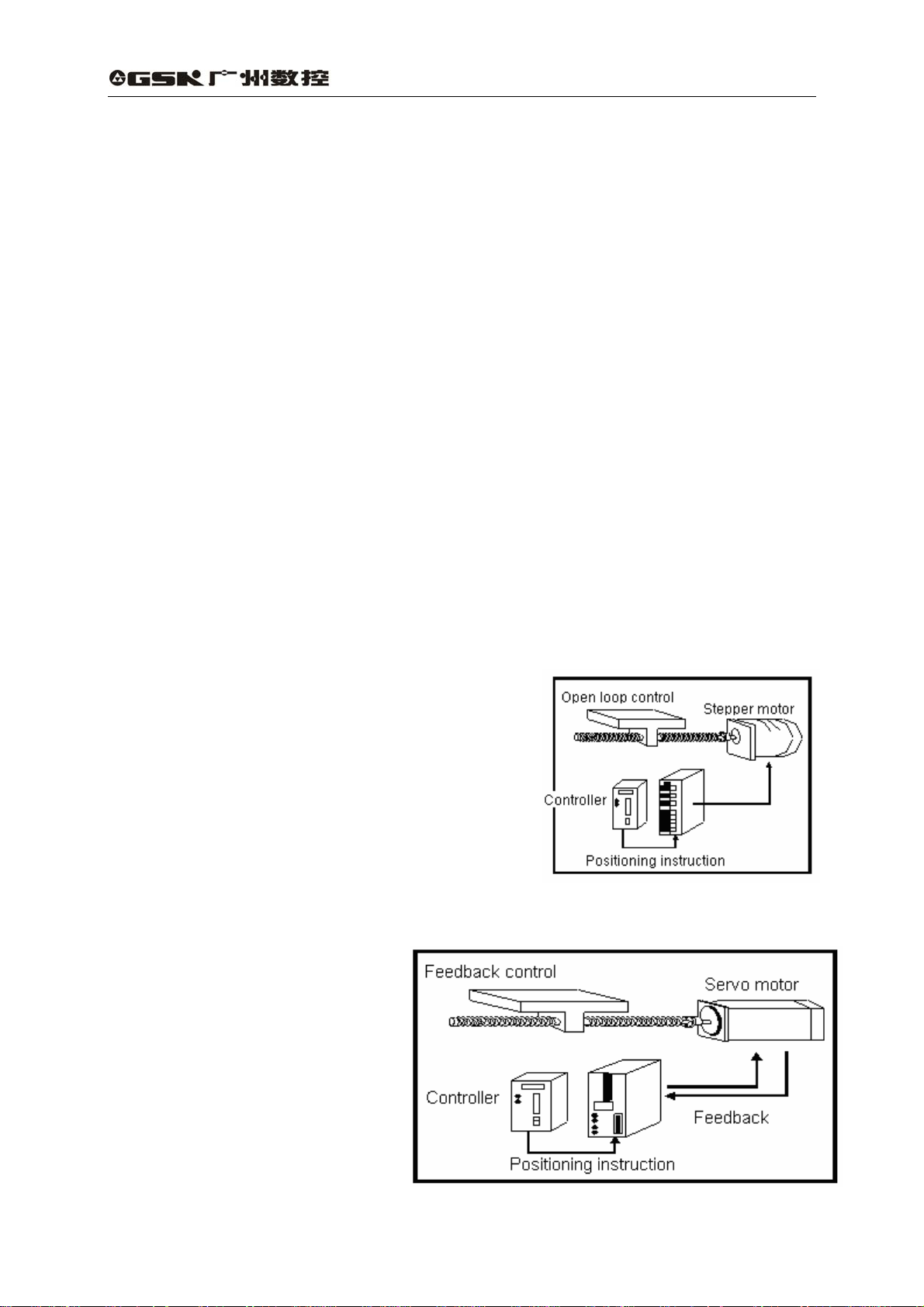
DA98A AC servo drive unit has following advantages compared to stepping system:
z No out-of-step
Servomotor is employed with an encoder, with position signal feedbacking to AC servo
drive unit, which comprise a semi-closed loop control system as it is combined with an open
loop position controller.
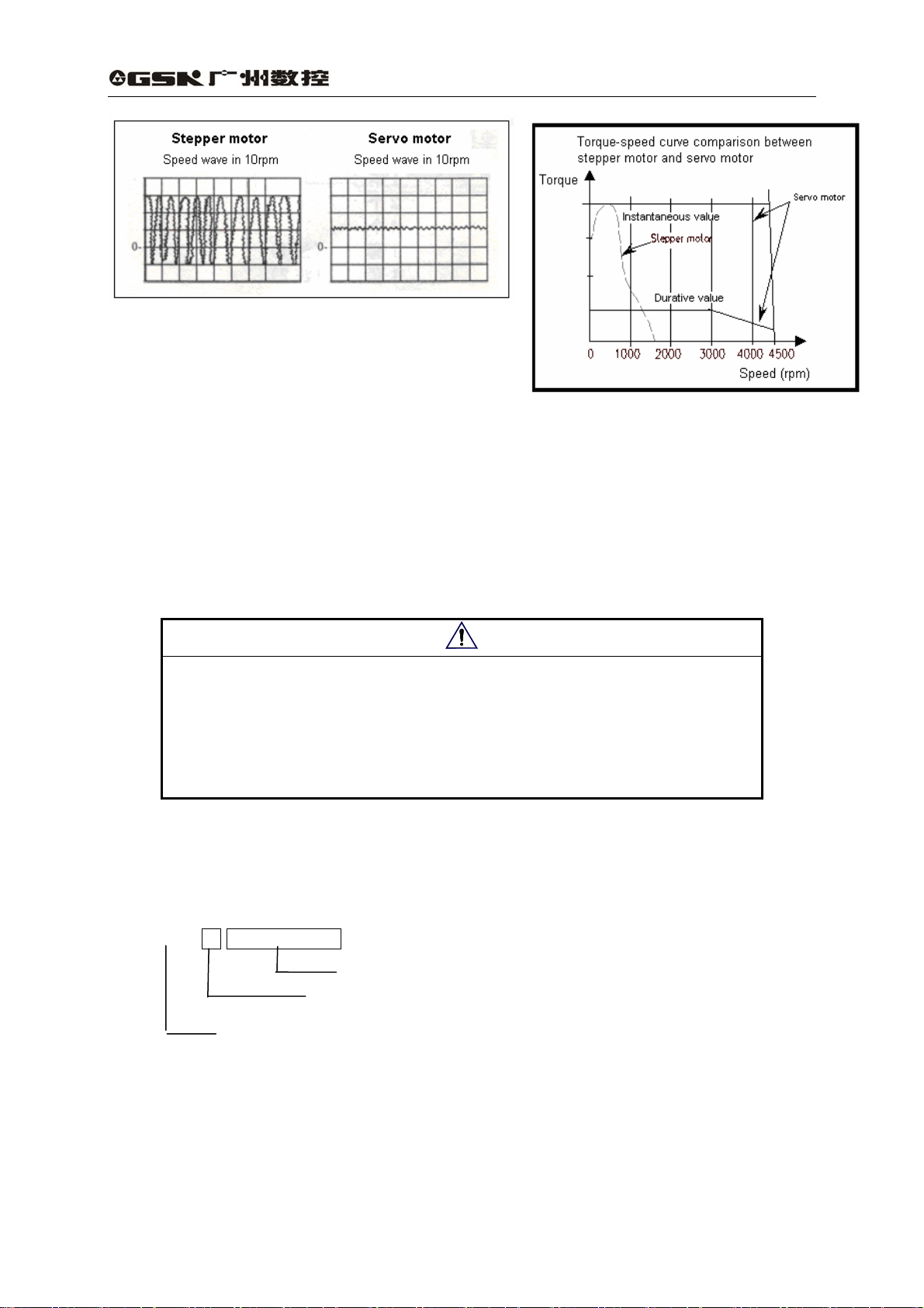
z Wide speed ratio, constant torque
The timing ratio is 1:5000,with stable torque
from low speed to high speed.
z High speed, high precision
The max. speed of servo motor can be 3000rpm,
and position precision of rotating is 1/10000r.
〖Note〗 There are different max. speeds for different servo motor models.
z Simple and flexible control
A proper setting for operating
mode, running performance of the
servo system by modifying
parameters is suitable for different
working requirements.
1
Page 11
DA98A AC Servo Drive Unit
User Manual
1.2 Reception check
1) Check the following items after delivery:
(1) Whether the packaging box is well or goods are damaged during transportation.
(2) Whether the AC servo drive unit, servo motor nameplates are consistent with the
ordered ones.
(3) Whether the accessories completely conforms to the packing list.
Note
z Do not install the servo drive unit which is damaged or lacks of
components.
z The AC servo drive unit must be used with the suited servo motor.
z Please contact with us or suppliers if there are any questions after
receiving goods.
2) Model signification:
(1) Model for AC servo drive unit
DA98A-10-110SJT-M040D
Suited servo motor model(GSK SJT series) 1※
Output power:2 digits (04,06…23) corresponding to 0.4~2.3KW 2※
Series code
※ 1:It can be matched with other domestic or imported servo motor which is needed to be
ordered. This drive unit default parameters are only suitable for SJT, STZ, Star series servo
motor. And the factory set parameters for other servo motors have been backup in the
EEPROM area. Backup recovery but default recovery operation should be performed when
the factory set parameters are to be recovered.
2
Page 12

※ 2:Medium or small power (less than or equal to 1.5KW) is the standard configuration, and the
medium power models(>1.5 and ≤2.3KW ) are employed with thicker radiators.
〖Note〗 Product model has been filled in the form before delivery and check the
DA98A AC Servo Drive Unit
User Manual
product with its nameplate.
(2) Servo motor model
DA98A AC servo drive unit can be matched with many domestic and abroad servo
motor models which can be selected by user order. Servo motor models of GSK SJT
series are introduced in Chapter 8 of this manual, and other servo motor models
information are provided with servo motor delivery.
3) Accessories
(1) DA98A AC servo drive unit accessories:
① User Manual 1
② Installation bracket 2
③ M4×8 countersink bolt 4
④ CN1 plug(DB25 female) 1 set (Note 1)
⑤ CN2 plug(DB25 male) 1 set (Note 2)
〖Note 1〗 Signal cable (3m) can be provided when it is matched with our controller.
〖Note 2〗 Feedback cable (3m) can be chosen by user when servo motor is provided by us.
(2) The primary accessories for servo motor are provided according to the servo motor
user manual.
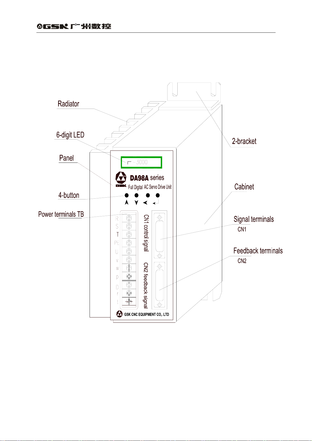
1.3 Outline
1) Outline of AC servo drive unit
3
Page 13
DA98A AC Servo Drive Unit
User Manual
Fig. 1-1 Outline of AC servo drive unit
4
Page 14
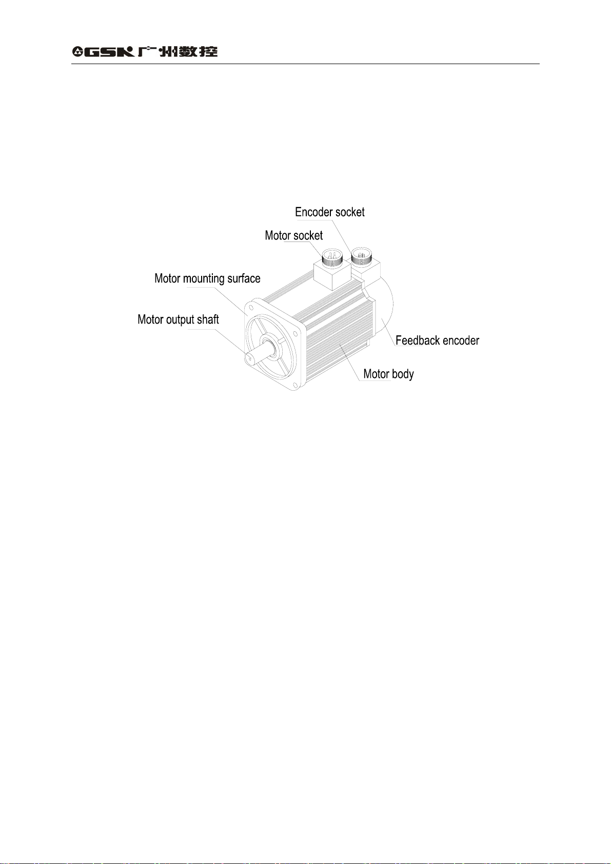
2) Outline of servo motor
DA98A AC Servo Drive Unit
User Manual
Fig. 1-2 Outline of SJT series servo motor
5
Page 15
DA98A AC Servo Drive Unit
User Manual
CHAPTER 2 INSTALLATION
Note
z Storage and installation for this unit must be complied to the environmental
requirement.
z Do not put the products into a pile to protect from being damaged or fallen down.
z Original packaging should be employed for products storage and delivery.
z Products which are damaged or shorten of parts must not be used.
z Fireproofing material should be used for the products installation and they should
not be installed on or near flammable objects.
z Servo drive unit should be installed into cabinet to prevent dust, corrosive air, liquid,
conductors and inflammable substances from entering it.
z The servo drive unit and motor should be protected from vibration and shock.
z The dragging of motor wire, motor shaft and encoder is unallowed.
2.1 Environmental condition
Item DA98A AC servo drive unit GSK SJT series servo motor
Usage temperature/
humidity
Storage/transport
temperature/humidity
Atmosphere
environment
Altitude
Vibration
Protection degree
0~+40℃(no icing)
below 95%RH(no condensation)
-40~55℃
95%RH(no condensation)
No corrosive gas,flammable gas,
oil fog or dust in cabinet
Altitude: below 1000m Altitude: below 1000m
Less than 0.5G(4.9m/s2)10-60HZ(non-continuous run)
IP43 IP65
-10~+40℃(no icing)
below 90%RH(no condensation)
-40~+55℃
below 80%RH(no condensation)
No corrosive gas,flammable gas, oil
fog or dust inside house(no insolation)
2.2 Installation of AC servo drive unit
Note
z It must be installed in a well protected cabinet.
z It must be installed by the specified direction and interval to get a good heat
rediating.
z To fix the unit on or near flammable objects that fire may occur is unallowed.
6
Page 16
DA98A AC Servo Drive Unit
1) Installation environment
(1) Protection
The servo drive unit without guard must be installed in a well protected electrical
cabinet to prevent corrosive or inflammable gas, liquid, electricity-conductor, metal
particls or oil fog from entering it.
(2) Temperature and humidity
Environmental temperature should be 0-40 , the long℃ -term safe working
temperature should be below 45 . And a good heat radiating should be done. ℃
(3) Vibration and shock
The measure to protect the AC servo drive unit from vibration should be below 0.5G
(4.9m/s
2
) and heavy pressure and impact during the unit installation should be avoided.
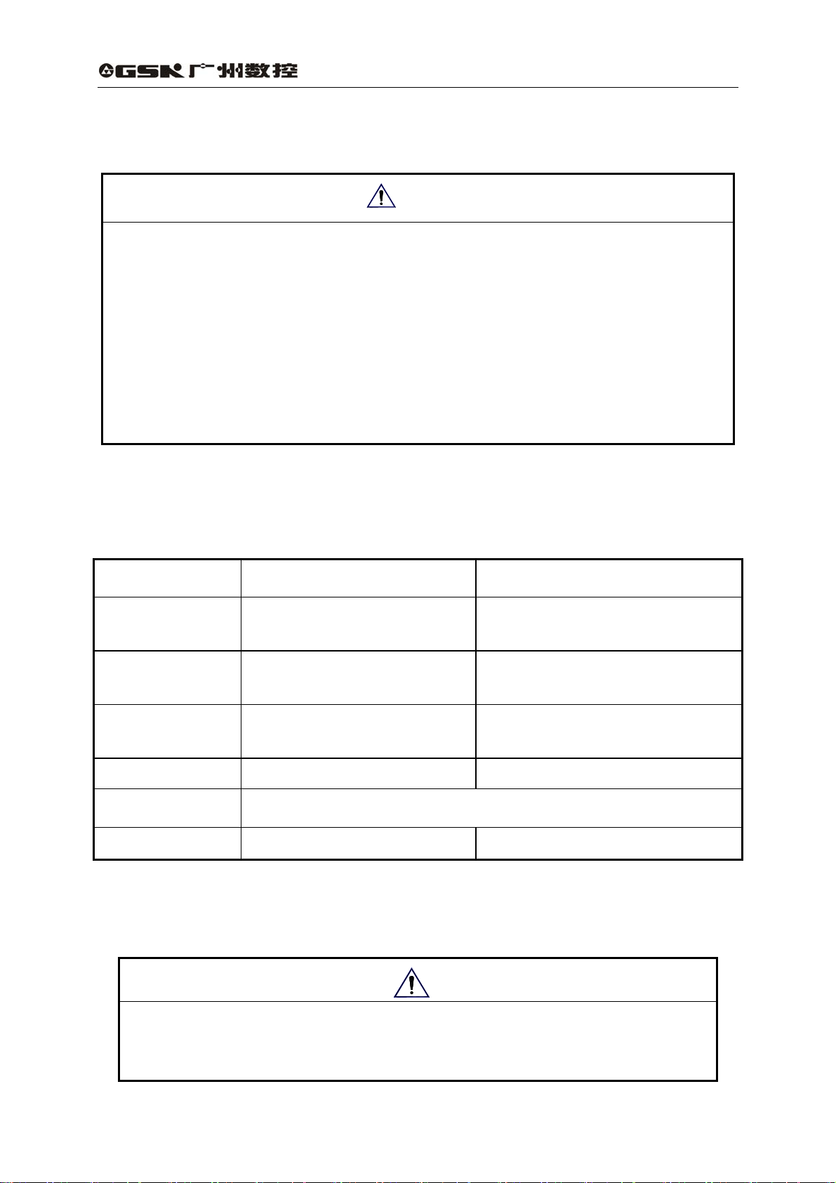
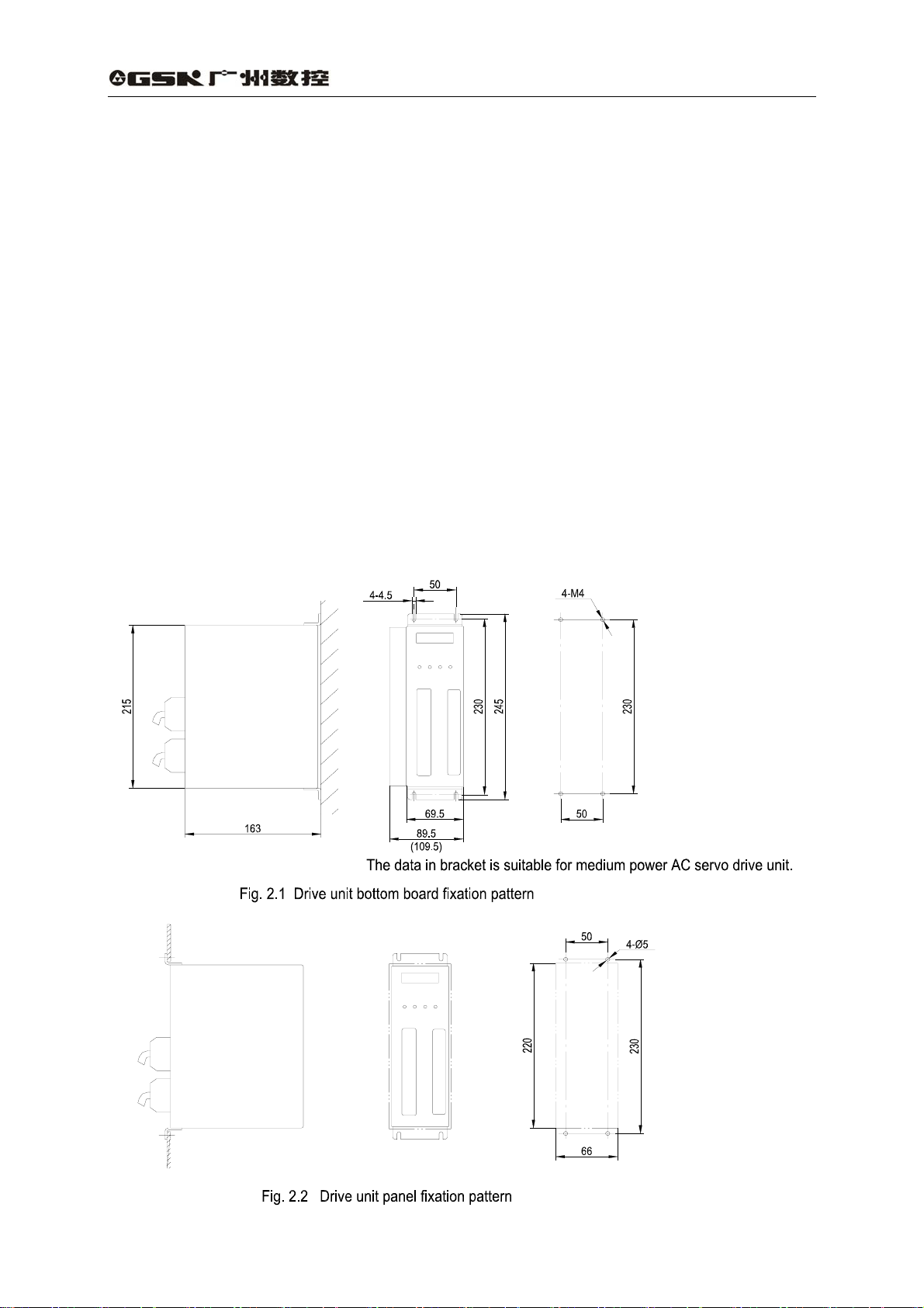
2) Installation method
(1) Fixation pattern
The drive unit can be fixed by bottom board or panel pattern with the direction
upright to the fixation plane.
Fig. 2.1 is a sketch map for bottom board fixation and Fig. 2.2 is for panel fixation.
User Manual
7
Page 17
DA98A AC Servo Drive Unit
User Manual
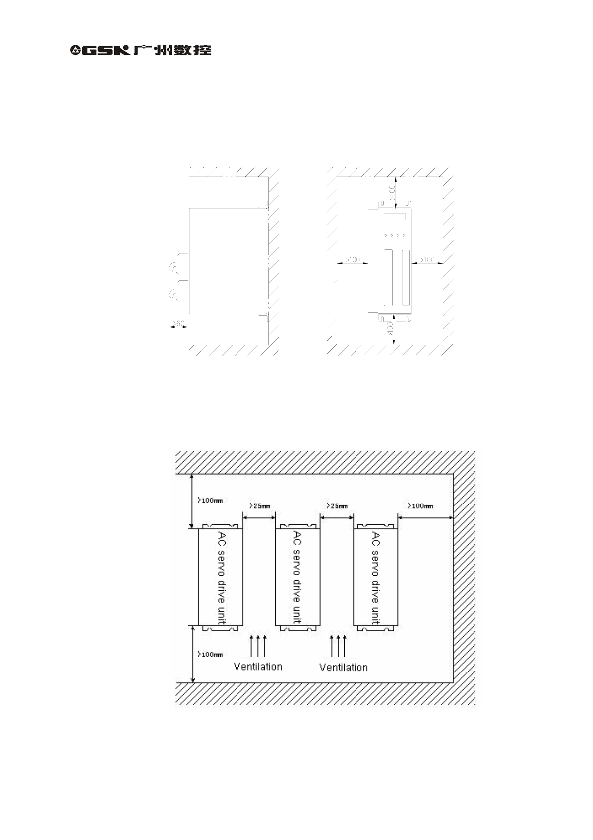
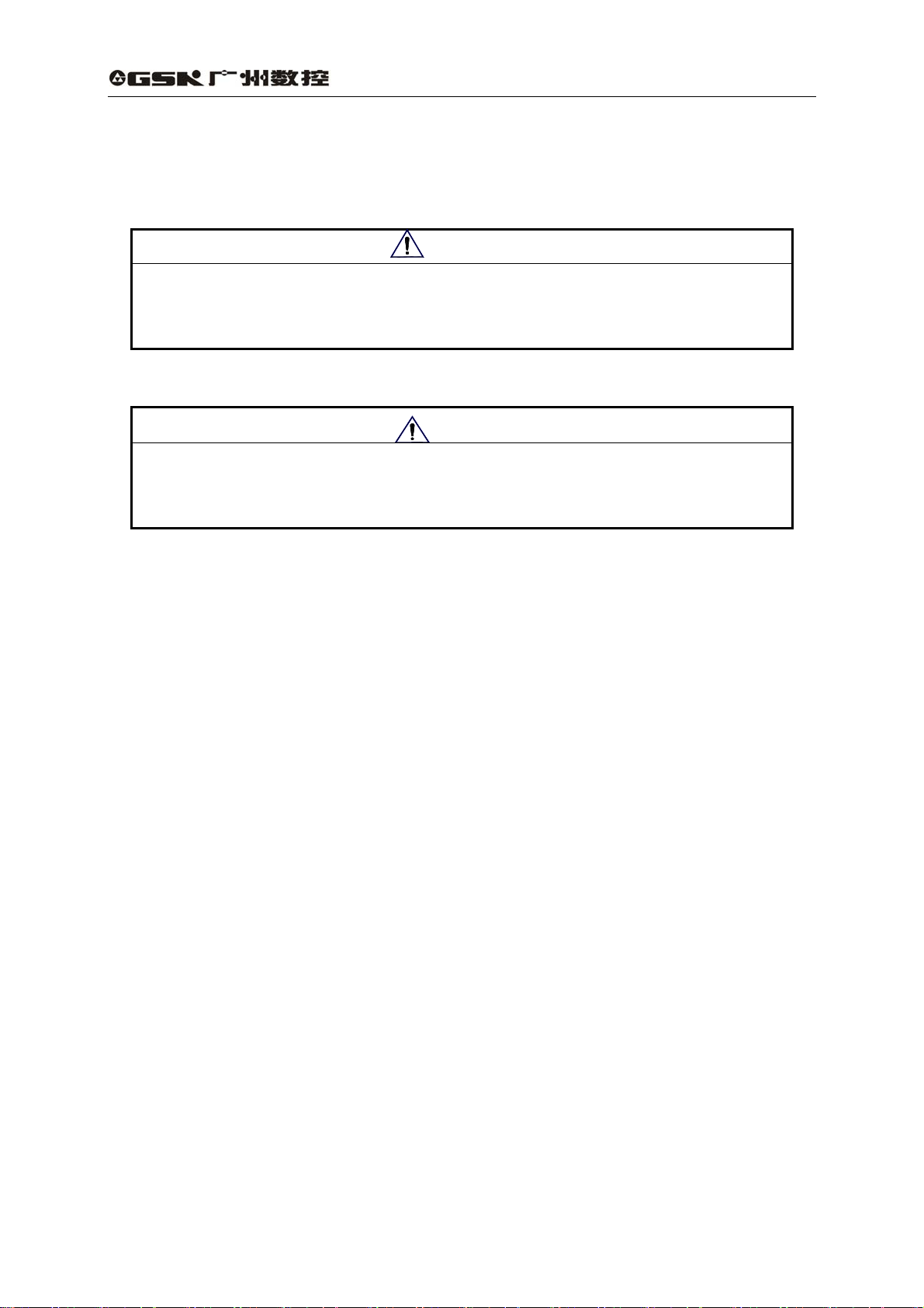
(2) Fixation interval
The fixation interval for single drive unit is shown in Fig. 2.3 and intervals for multiple
drive units are shown in Fig. 2.4. The interval for actual fixation should be as larger as
possible to get a good heat dissipation.
Fig. 2.3 Fixation interval for single drive unit
Fig. 2.4 Fixation intervals for multiple drive units
(3) Heat dissipation
There should be convective air blown to the drive unit radiator in the cabinet to prevent
the ambient temperature of drive unit from continuous rising.
8
Page 18

2.3 Servo motor installation
DA98A AC Servo Drive Unit
User Manual
z Motor shaft or encoder hammering is impermissible.
z Do not drag the motor shaft, outlet wires or encoder.
z Motor shaft cannot be overloaded, otherwise the motor may be
damaged.
z The motor must be secured firmly and there should be measures
against loose.
1)Installation environment
(1) Guard
GSK SJT series are not employed with waterproof device, so prevent liquid from
splashing onto the motor and oil or water from entering into the motor along its lead
wires and shaft.
〖Note〗 Please make a mark in order if waterproof servo motor is needed.
(2) Temperature and humidity
Environmental temperature should be kept in -10~+40 (no icing)℃ . Measures of
forced heat radiation should be done if there is little space or equipment emitting
heat around when the motor’s temperature rises owing to long-term run.
Note
The environmental humidity should be no more than 90%RH and there is no
condensation around.
(3) Vibration
The servo motor should be fixed in a place away from vibration and its vibration
should be less than 0.5G(4.9m/s2).
2)Installation method
(1) Installation type
SJT series motors are installed by flange installation type and it may be installed in
every direction.
(2) Installation cautions:
z Do not hammer the motor or its shaft to prevent the encoder from damaging. Helical
tools should be employed to connect or disconnect the parts.
z SJT series motor cannot be loaded with heavy axial, radial loading. Flexible shaft
coupling is recommended to connect the load.
z Anti-loose washer should be employed to secure the motor from loose.
9
Page 19
DA98A AC Servo Drive Unit
User Manual
CHAPTER 3 WIRING
Warning
● The system wiring or check can only be done by qualified personnels.
● Wiring and check can only be done in 5 minutes to avoid electric shock after the
power supply is cut off.
Caution
z The wiring must be done by terminal voltage and polarity to avoid equipment
damage or personnel injury.
z Drive unit and servo motor must be well grounded.
3.1 Standard wiring
The external connection of drive unit is relative to control mode.
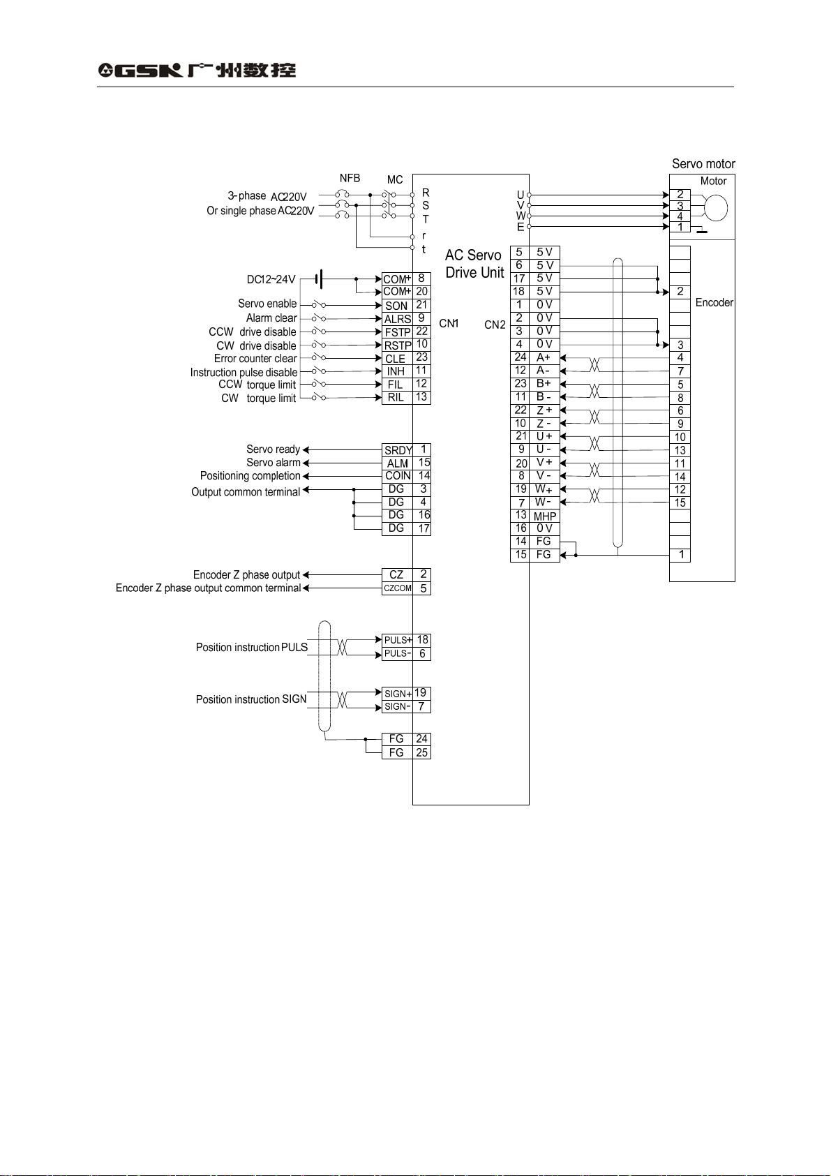
1) Position control mode
Fig. 3.1 shows the standard wiring of position control mode.
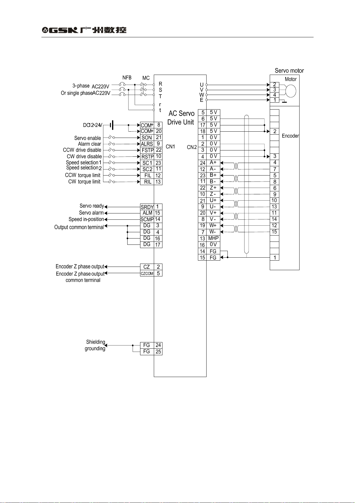
2) Speed control mode
Fig. 3.2 shows the standard wiring of speed control mode.
3) Wiring
(1) Power supply terminal TB
z Wire diameter : wire diameter of R, S, T, PE, U, V, W terminals
2
≥1.5mm
z Grounding: the grounding wire should be thick, PE terminals of drive unit and servo
motor should be eathed and their resistances are less than 0.1Ω.
z The terminal connection is employed with JUT-1.5-4 pre-insulation cold-press
terminals, and it must be secured firmly.
z It is suggested that three-phase isolation transformer is employed for the power to
avoid the electric shock.
z It is suggested that power supply is connected to a noise filter to improve
anti-interference capability.
z Install non-fusing breaker to cut off external power supply in time when the drive
(AWG14-16),wire diameter of r, t terminals≥1.0 mm2(AWG16-18).
10
Page 20
unit is at fault.
DA98A AC Servo Drive Unit
User Manual
(2) Control signal CN1, feedback signal CN2
2
z Wire diameter: it is employed with shield cable, wire diameter ≥0.12mm
and shield layer should be connected with FG terminal.
z Wire length: the cable length should be as possible as short, the CN1 cable should be
less than 3m, and the feedback signal CN2 cable should be less than 20m.
z Wiring distribution: it should be far away from power circuit against antiinterference.
z Inductive components (coil) should be installed with surge absorbing elements: DC
coil should be reversely connected with parallel freewheeling diode and AC coil
should be connected with parallel RC absorption circuit.
Note
z U, V, W should be connected with the corresponding motor winding one by one and
reverse connection is unallowed.
z Cables and wires must be secured and their approaching to the drive unit radiator
and motor should be avoided to ensure the insulation.
z Don’t touch drive unit or motor within 5 minutes after the power supply is cut off
because there is still a residual voltage on the electrolytic capacitance.
11
(AWG24-26)
Page 21
DA98A AC Servo Drive Unit
User Manual
Fig. 3.1 Wiring of position control mode
12
Page 22
DA98A AC Servo Drive Unit
User Manual
Fig. 3.2 Wiring of speed control mode
13
Page 23
3.2 Terminals function
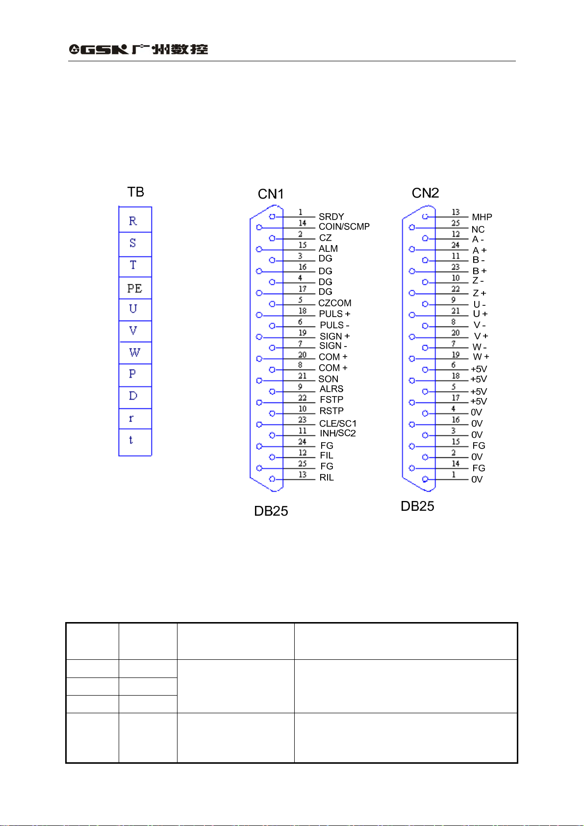
1) T erminals configuration
Fig. 3.3 is the interface terminal configuration of servo drive unit. TB is terminal block;
CN1 is DB25 connector assembly,the socket is male type and the plug is female type;
CN2 is DB25 connector assembly too, socket is female type and plug is male type.
DA98A AC Servo Drive Unit
User Manual
Interface terminals configuration of AC servo drive unit`
2) Power supply terminal TB
Table3.1 Power supply terminal TB
Terminal
No.
TB-1
TB-2
TB-3
TB-4 PE System be grounded
14
Terminal
sign
R
S
T
Signal name Function
Main power supply
(single phase or
three-phase)
Main power supply input terminals
~220V 50Hz
Note: Do not connect them with motor output
terminals U, V, W.
Ground terminal
Ground resistance<0.1Ω
Common terminal grounded of servo motor
output and power supply input
Page 24

TB-5 U
TB-6 V
TB-7 W
TB-8 P Standby
TB-9 D Standby
TB-10
TB-11
r
t
Servo motor output
Control power supply
single phase
DA98A AC Servo Drive Unit
Output terminals of servo motor must be
connected correspondingly with U, V, W
terminals of motor
Power supply input terminal of control circuit
~220V 50Hz
3) Control terminal CN1
Control mode name for short:
P for position control mode
S for speed control mode
Table 3.2 Input/output terminal CN1 of control signal
User Manual
Terminal
No.
CN1-8
CN1-20
CN1-21 Servo enable SON Type 1
CN1-9 Alarm clear ALRS Type 1
CN1-22
Signal
name
Power
supply
Positive of
input
terminals
CCW drive
stop
Sign I/O Mode Function
COM+ Type 1
FSTP Type 1
Power supply positive of input terminals
Photoelectric coupling used for driving input
terminals
DC12~24V,Current≥100mA
Input terminal of servo enable
SON ON:AC servo drive unit enable
SON OFF : AC servo drive unit off and
disabled and the motor is in free
state.
Note 1 The motor must be resting before it
is switched from SON OFF to SON ON;
Note 2 Wait for 50ms before inputting new
command after it is switched to SON ON.
Alarm clear input terminal
ALRS ON: alarm clear
ALRS OFF: alarm
Note For the alarm whose code is more
than 8 it can’t be cleared by this means. It
needs to cut off the power for reparation and
then repower.
CCW drive stop input terminal
FSTP ON:CCW drive enable
FSTP OFF:CCW drive stop
Note 1 It is used for mechanical overload.
When the switch is put for OFF, the torque in
CCW direction is kept for 0.
Note 2 This function can be shielded by
parameter No.20 setting or always keep the
switch for ON.
15
Page 25

CN1-10
CN1-23
CW drive
stop
Deviator
clear
Speed
selection 1
DA98A AC Servo Drive Unit
RSTP Type 1
CLE Type 1 P
SC1 Type 1 S
User Manual
CW drive stop input terminal
RSTP ON:CW drive enable
RSTP OFF:CW drive stop
Note 1 It is used for mechanical overload.
When the switch is put for OFF, the torque in
CW direction is kept for 0.
Note 2 This function can be shielded by
parameter No.20 setting or always keep the
switch for ON.
Input terminal of position deviator clear
CLE ON: position deviator clear in position
control
Input terminal of speed selection 1
The combination of SC1 and SC2 is used for
selecting different internal speed in speed
control mode
SC1 OFF,SC2 OFF: internal speed 1
SC1 ON,SC2 OFF: internal speed 2
SC1 OFF,SC2 ON: internal speed 3
SC1 ON,SC2 ON: internal speed 4
Note The values of internal speed 1~4
can be modified by parameters.
Terminal
No.
CN1-11
CN1-12
Table 3.2 Input/output terminal CN1 of control signal (continued)
Signal name Sign I/O Mode Function
Instruction
pulse
disable
INH Type 1 P
Terminal of position instruction pulse input
disable
INH ON: input disable of instruction pulse
INH OFF: instruction pulse input valid
Input terminal of speed selection 2
The combination of SC1 and SC2 is used for
selecting different internal speed in speed
Speed
selection 2
SC2 Type 1 S
control mode.
SC1 OFF,SC2 OFF: internal speed 1
SC1 ON:SC2 OFF: internal speed 2
SC1 OFF,SC2 ON: internal speed 3
SC1 ON,SC2 ON: internal speed 4
CCW input terminal of CCW torque limit
FIL ON : CCW torque is limited by the
CCW torque
limit
FIL Type 1
parameter No.36.
FIL OFF: CCW torque is not limited by the
parameter No.36.
Note Whether FIL is valid or not, CCW
torque is also limited by parameter No.34.
16
Page 26

CN1-13
CN1-1
CN1-15
CN1-14
CN1-3
CN1-4
CN1-16
CN1-17
CN1-2
CN1-5
CN1-18 PULS +
CN1-6
CN1-19 SIGN +
CN1-7
CN1-24
CN1-25
CW torque
limit
Servo ready
output
Servo alarm
output
Positioning
completion
output
Speed
in-position
output
Common
terminals of
output
Encoder Z
phase
output
Common
terminal of
encoder Z
phase
output
PLUS input
of instruction
pulse
SIGN input
of instruction
pulse
Shielding
grounding
RIL Type 1
SRDY Type 2
ALM Type 2
COIN Type 2 P
SCMP Type 2 S
DG
CZ Type 2
CZCOM Common terminal of encoder Z phase
PULS -
SIGN -
FG Shielding grounding terminals
DA98A AC Servo Drive Unit
Type 3 P
Type 3 P
User Manual
Usually, parameter No.34> parameter No.36.
Input terminal of CW torque limit
RIL ON:CW torque is limited by parameter
No.37.
RIL OFF : CW torque is not limited by
parameter No.37.
Note Whether RIL is valid or not, CW
torque is also limited by parameter No.35.
Usually, parameter No.35> parameter No.37.
Servo ready output terminal
SRDY ON: If control and main power are
normal, the AC servo drive unit has no alarm,
the servo ready is set for ON.
If main power is not making, or the AC servo
drive unit has an alarm, the servo ready is set
for OFF.
Output terminal of servo alarm
ALM ON: If AC servo drive unit has no alarm,
servo alarm is set for ON.
ALM OFF:If AC servo drive unit has an alarm,
servo alarm is set for OFF.
Output terminal of positioning completion
COIN ON: When the position deviator value
is within the set positioning range, the
positioning completion is set for ON.
Output terminal of speed in-position
SCMP ON: When the actual speed reaches
or exceeds the speed specified, speed
in-position is set for ON.
Common ground terminals of control signal
output terminals(except CZ)
Output terminal of encoder Z phase
Z phase pulse output of servo motor
photoelectric encoder
CZ ON: Z phase signal occuring
Input terminals of external instruction pulse
Note The pulse input mode is set by
parameter 04.
① instruction pulse +sign mode
② CCW/CW instruction pulse mode
17
Page 27

DA98A AC Servo Drive Unit
User Manual
4) Feedback signal terminal CN2
Table 3.3 CN2 input/output terminal of encoder signal
Terminal
No.
CN2-5
CN2-6
CN2-17
CN2-18
CN2-1
CN2-2
CN2-3
CN2-4
CN2-16
CN2-24
CN2-12
CN2-23
CN2-11
CN2-22
CN2-10
CN2-21
CN2-9
CN2-20
CN2-8
CN2-19
CN2-7
Signal name
Power supply
output (+)
Power supply
output (-)
Encoder (A+)
input
Encoder (A-)
input
Encoder (B+)
input
Encoder (B-)
input
Encoder (Z+)
input
Encoder (Z-)
input
Encoder (U+)
input
Encoder (U-)
input
Encoder (V+)
input
Encoder (V-)
input
Encoder (W+)
input
Encoder (W-)
input
Terminal mark
Mark I/O Mode
+5V
0 V
A+
Type 4
A-
B+
Type 4
B-
Z+
Type 4
Z-
U+
Type 4
U-
V+
Type 4
V-
W+ Connecting with servo motor
Type 4
W-
Color
The servo motor photoelectric
encoder is employed with +5V
power supply; multi-core cable in
parallel are used as the length of
cable is too long.
Connecting with servo motor
photoelectric encoder(A+)
Connecting with servo motor
photoelectric encoder(A-)
Connecting with servo motor
photoelectric encoder(B+)
Connecting with servo motor
photoelectric encoder(B-)
Connecting with servo motor
photoelectric encoder(Z+)
Connecting with servo motor
photoelectric encoder(Z-)
Connecting with servo motor
photoelectric encoder(U+)
Connecting with servo motor
photoelectric encoder(U-)
Connecting with servo motor
photoelectric encoder(V+)
Connecting with servo motor
photoelectric encoder(V-)
photoelectric encoder(W+)
Connecting with servo motor
photoelectric encoder(W-)
Function
3.3 I/O Interface principle
1) Input interface of switching volume
18
Page 28

K
de
DA98A AC Servo Drive Unit
User Manual
COM+
12~24V
SW
Fig. 3.4 Type 1 Input interface of switchin g volume
(1) Power suppy is provided by user,DC12~24V,current≥100mA;
(2) Note If current polarity is connected reversely, the drive unit will not run.
2) Output interface of switching volume
max 50mA
max 25V
AC servo drive unit side
4.7
servo amplifier
AC servo drive unit side
Fig. 3.5 Type 2 Output interface of switching volume
(1) External power supply is provided by user; if its polarity is connected reversely, the
drive unit will be damaged.
(2) The output is by collector open circuit, and its max. current is 50mA, external max.
power supply voltage is 25V. So the load of switching volume output signal must
conform to these restrictions. If the load exceeds them or the output is connected
directly with power supply, the servo drive unit may be damaged.
(3) If the load is an inductive one such as relay, the both terminals of load must be
connected with freewheeling diode in parallel reversely. If the freewheeling diode is
connected reversely, the servo drive unit may also be damaged.
3) Pulse volume input interface
PULS+
PULS-
220
Fig. 3.6 Type 3 Differential drive mode of pulse volume input interface
SIGN+
SIGN-
220
19
Servo amplifier
AC servo drive unit si
Page 29

R
R
DA98A AC Servo Drive Unit
User Manual
VCC
PULS+
PULS-
AC servo drive unit side
220
SIGN+
SIGN-
220
Fig. 3.7 Type 3 Single terminal drive mode of pulse volume input interface
(1) Differential drive mode is recommended to be used to transmit pulse data.
(2) AM26LS31, MC3487 or the similar RS422 linear driver are employed in the differential drive
mode.
(3) Action frequency will be reduced in single terminal drive mode. Decide the value of
resistance R according to the pulse input circuit, the 10~15mA drive current and the max.
25V voltage of the external power. Practical data: VCC=24V,R=1.3K~2K;VCC=12V,
R=510~820Ω;VCC=5V,R=82~120Ω.
(4) In single terminal drive mode, the external power supply is provided by user. And if its
polarity is connected reversely, the servo drive unit may be damaged.
(5) Refer to Table 3.4 about pulse input form, arrowhead represents counting edge, and pulse
input time sequence and parameter are shown in Table 3.5.
Pulse instruction
type
Pulse string
Sign string
CCW pulse string
CW pulse string
PULS
SIGN
PULS
SIGN
Table 3.4 Pulse input form
CCW CW
Parameter setting
value
0
Instruction pulse +
signal
1
CCW pulse /CW pulse
20
Page 30

DA98A AC Servo Drive Unit
User Manual
Table 3.5 Time sequence parameter of pulse input
Parameter Differential drive input Single terminal drive input
T
ck
>2μs >5μs
Th >1μs >2.5μs
Tl >1μs >2.5μs
Trh <0.2μs <0.3μs
Trl <0.2μs <0.3μs
Ts >1μs >2.5μs
t
>8μs >10μs
qck
Tqh >4μs >5μs
Tql >4μs >5μs
t
<0.2μs <0.3μs
qrh
t
<0.2μs <0.3μs
qrl
Tqs >1μs >2.5μs
t
h
t
ck
90%
PULS
10%
t
t
t
rh
90%
SIGN
10%
t
rl
CW
Fig. 3.8 Time sequence of pulse +sign inpu t interface (max. pulse frequency 500kHz)
t
h
90%
PULS
10%
t
rh
90%
SIGN
10%
s
t
rh
t
ck
t
l
t
rl
CCW
t
l
t
s
s
t
rl
CW
CCW
Fig. 3.9 Time sequence of CCW/CW pulse input interface (max. pulse freq uency 500kHz)
21
t
rh
t
rl
CW
Page 31

r
,B,Z,U,V,
DA98A AC Servo Drive Unit
User Manual
4) Input interface of servo motor photoelectric encoder
Motor side
X+
X-
X=A
Fig. 3.10 Input interface of servo motor photoelectric encod er
W
AC servo drive unit side
AM26LS32
22
Page 32
DA98A AC Servo Drive Unit
User Manual
CHAPTER 4 PARAMETERS
Note
z Personnel for parameters setting must have a good knowledge of the parameter
meanings and the false setting may cause damage to the equipments or injury to
people.
z Parameter adjustment is suggested to be done in the servo motor dry run mode.
z The motor parameter defaults the servo motors of GSK SJT series,Huazhong STZ,
Star series, and the corresponding parameters must be adjusted if other servo
motor is used, otherwise, the motor may run abnormally.
4.1 Parameter list
Values set by factory in Table 4.1 are applicable for the AC servo drive unit matching GSK
110SJT-M020E(2N•m, 3000r/min)motor. The parameters for different motors are not identical.
Table 4.1 Parameter list
No. Name
0 Password
1 Model code
2 Software version (read-only)
3 Initial display state
4 Control mode selection
5 Speed proportional gain
6 Speed integration time constant
7 Torque instruction filter
8 Speed detecting lowpass filter
9 Position proportional gain
10 Position feedforward gain
11 Lowpass filter cut-off frequency of
position feedforward
12 Frequency division numerator of
position instruction pulse
13 Frequency division denominator of
position instruction pulse
14 Position instruction pulse input mode
Applicable
mode
P,S
P,S
P,S
P,S
P,S
P,S
P,S
P,S
P,S
P 1~1000 30
P 0~100 0
P 1~1200 300
P 1~32767 1
P 1~32767 1
P 0~1 0
Range
0~9999 315
0~69 60*
* *
0~20 0
0~5 0
5~2000 170*
1~1000 50*
1~500 30
1~500 120
Value set by
factory
Unit
Hz
%
%
1/s
%
Hz
23
Page 33

DA98A AC Servo Drive Unit
User Manual
15 Position instruction pulse reverse
direction
16 Positioning completion range
17 Position out-of-tolerance detection
range
18 Position out-of-tolerance error invalid
19 Position instruction smooth filter
20 Drive stop input invalid
21 JOG running speed
22 Reserved
23 Max. speed limit
24 Internal speed 1
25 Internal speed 2
26 Internal speed 3
27 Internal speed 4
28 In-position speed
29 Reserved
30 Conversion numerator of linear speed
31 Conversion denominator of linear
speed
32 Decimal point of linear speed
33 Reserved
34 Internal CCW torque limit
35 Internal CW torque limit
36 External CCW torque limit
37 External CW torque limit
38 Trial speed, JOG torque limit
39 Reserved
40 Acceleration time constant
41 Deceleration time constant
P 0~1 0
P 0~30000 20
P 0~30000 200
P 0~1 0
P 0~30000 0
P,S
S -3000~3000 120
P,S
S -3000~3000 0
S -3000~3000 100
S -3000~3000 300
S -3000~3000 -100
S 0~3000 500
P,S
P,S
P,S
P,S
P,S
P,S
P,S
S 0~300 100
S 1~10000 0
S 1~10000 0
0~1 0
0~4000 3600
1~32767 10
1~32767 1
0~5 3
0~300 300*
-300~0 -300*
0~300 100
-300~0 -100
Pulse
×100
pulse
0.1ms
r/min
r/min
r/min
r/min
r/min
r/min
r/min
%
%
%
%
%
ms
ms
24
Page 34

4.2 Parameter function
DA98A AC Servo Drive Unit
Table 4.2 Parameter function
User Manual
No. Name Function
① It is used for parameter to be modified by mistake. Usually
set this parameter for a required password and then set the
parameter to be modified. After debugging, set this
parameter for 0 to ensure it not to be modified by mistake
later.
② The password is classified into several levels which
0 Password
1 Model code
Software version
2
(read-only)
correspond to user parameter, system parameter and all the
other parameters.
③ Use the model password to modify model parameter (No.1)
and the model parameter can’t be modified by other
password.
④ The user password is 315.
⑤ The drive unit model password is 385.
① It corresponds to the AC servo drive unit and motor with
different power level in the same series.
② Different models correspond to different parameter default
value. Ensure the parameter is right when using default
parameter recovery function.
③ This parameter should be set again after reparation for
EEPROM alarm (No.20), then recover the default
parameter. Or else the drive unit may act abnormally or be
damaged.
④ First set the password(parameter No. 0) for 385, then
modify this parameter.
⑤ Refer to this chapter for the parameters significance.
Software version can be viewed but cannot be modified. *
Parameter
range
0~9999
0~69
25
Page 35

3 Initial display state
4
Control mode
selection
Select display state after the AC servo drive unit is
powered on.
0:Motor speed display;
1:Current position lower 5-bit display;
2:Current position higher 5-bit display;
3:Position instruction (instruction pulse accumulation ) lower
5-bit display;
4:Position instruction (instruction pulse accumulation ) higher
5-bit display;
5:Position error lower 5-bit display;
6:Position error higher 5-bit display;
7:Motor torque display;
8:Motor current display;
9:Linear speed display;
10:Control mode display;
11:Position instruction pulse frequency display;
12:Speed instruction display;
13:Torque instruction display;
14:Rotor absolute position display in one revolution;
15:Input terminal state display;
16:Output terminal state display;
17:Encoder input signal display;
18:Running state display;
19:Alarm code display;
20:Reserved.
Set control mode of drive unit by this parameter:
0:Position control mode;
1: Speed control mode
2:Trial run control mode;
3:JOG control mode;
4:Encoder zeroing mode;
5:Open loop mode(for motor and encoder test)
① Position control mode Position instruction is input from
the pulse input interface.
② Speed control mode Speed instruction is input from the
input terminal. The internal speed is selected by the
combination of SC1 and SC2.
SC1 OFF,SC2 OFF :internal speed 1
SC1 ON,SC2 OFF :internal speed 2
SC1 OFF,SC2 ON :internal speed 3
SC1 ON,SC2 ON :internal speed 4
③ Trial run control mode Speed instruction is input from the
keyboard, which is used for drive unit and servo motor test.
④ JOG control mode In this mode, pressing down ↑ key and
holding it on, the motor runs by JOG speed, releasing the
key, the motor stops and keeps zero speed; pressing down
↓ key and holding it on, the motor runs reversely by JOG
speed; releasing the key, the motor stops and keeps zero
speed.
⑤ Encoder zeroing mode It is used for encoder factory
zeroing adjustment of motor.
DA98A AC Servo Drive Unit
User Manual
0~20
0~5
26
Page 36

Speed proportional
5
Speed integration
6
7
8
9
10
11
time constant
Torque instruction
Speed detecting
lowpass filter
Position
proportional gain
Position
feedforward gain
Lowpass filter
cut-off frequency of
position
feedforward
gain
filter
① Set the proportional gain of speed loop regulator.
② The bigger the setting value is, and the higher the gain is,
the bigger the rigidity is. The parameter value is defined by
specific AC servo drive unit model and load. Generally, the
bigger the load inertia, the bigger the setting value is.
③ Set the bigger value if there is no oscillation in system.
① Set integral time constant of speed loop regulator.
② The bigger the setting value is, the faster the integral speed
and the smaller the rigidity is. The parameter value is
defined by specific AC servo drive unit model and load.
Generally, the larger the load inertia, the larger the setting
value is.
③ Set bigger value if there is no oscillation in system.
① Set the torque instruction filter characteristic. It can
suppress the the resonance resulted by torque (piercing
noise from motor).
② If the motor makes piercing noise in running, please reduce
this parameter.
③ The smaller the value is and the lower the cut-off frequency
is, the smaller the noise from the motor is. If the load inertia
is too large, reduce the setting value properly. If the value is
too small, the response will be slow which may cause
instability.
④ The larger the value is and the higher the cut-off frequency
is, the faster the response is. If a higher mechanic rigidity is
needed, increase the setting value properly.
① Set speed detecting lowpass filter characteristics.
② The smaller the setting value is, the lower the cutoff
frequency, the smaller the motor noise is. Properly reduce
setting value if the load inertia is too large. If the value is too
small, the response will be slow which may cause
oscillation.
③ The larger the value is and the higher the cutoff frequency
is, the faster the speed feedback response is. Properly
increase setting value if faster speed response is needed.
① Set proportional gain of position loop regulator.
② The larger the setting value is, the higher the gain is, and
the larger the rigidity is in the same frequency instruction
pulse, the smaller the position lag is. If the value is too large,
the oscillation or overshooting may occur.
③ The parameter value is defined by specific servo drive unit
model and load.
① Set the feedforward gain of the position loop.
② If it is set for 100%, it means the position lag is always 0 in
any instruction pulse frequency.
③ If the feedforward gain of the position loop increases, the
quick response characteristic of the control system will be
enhanced. But it will make the system position loop unstable
and oscillation may occur.
④ Unless the high response characteristic is needed, the
feedforward gain of the position loop is usually 0.
Set the cutoff frequency of lowpass filter of position loop ①
feedforward.
The filter is used for enhancing the stability of complex ②
position control.
DA98A AC Servo Drive Unit
User Manual
5 Hz
~2000Hz
1 ~1000
1%~500%
1%~500%
1/s
~1000 /s
0%~100%
1Hz~1200Hz
27
Page 37

Frequency division
×
×
×
×=×
P
12
numerator of
position instruction
pulse
Frequency division
13
denominator of
position instruction
pulse
Position instruction
14
pulse input mode
DA98A AC Servo Drive Unit
User Manual
① Set frequency division/multiplication (electronic gear) of
position instruction pulse.
② In position control mode, various pulse resource can be
conveniently matched by parameter No.12, No.13 setting to
get a desirable control resolution( i.e. angle/pulse) by user.
③
=× CNGP
4
P:pulse amount of input instruction;
G:electronic gear ratio; G= frequency division numerator /
frequency division denominator
N:motor rotating circles;
1~32767
C:photoelectric encoder pulses/rev, this system C=2500
④ 〖Example〗If the input instruction pulse is 6000, and servo
motor revolution is 1:
×
G
6000
CN
=
5
4250014
=
3
then parameter No.12 is set for 5 and No. 13 is set for 3.
Range of electronic gear ratio recommended is: ⑤
1
50
50
≤≤ G
Refer to parameter No.12. 1~32767
① Set the input mode of position instruction pulse.
② 2 input modes by parameter setting:
0: pulse+sign
1: CCW pulse/CW pulse
③ Viewed from the servo motor shaft axially, the
0~1
counterclockwise rotation is defined as negative.
④ Viewed from the servo motor shaft axially, the clockwise
rotation is defined as negative.
Position instruction
15
16
pulse reverse
Positioning
completion range
Position
17
out-of-tolerance
detection range
Position
out-of-tolerance
18
error invalid
direction
Set for:
0:normal
1:position instruction pulse reverse direction
① Set positioning completion pulse range in position control
mode.
② This parameter provides factors for the drive unit judging
whether the positioning is completed in position control.
When the remaining pulses in position deviator is less than
or equal to the setting value by this parameter, the drive unit
defaults that the positioning is completed and the signal for
it is COIN ON, otherwise, it is COIN OFF.
③ It outputs positioning completion signal COIN in position
control mode, and speed in-position signal SCMP in other
control mode.
① Set the range of position out-of-tolerance alarm detection.
② In position control mode, the drive unit gives position
out-of-tolerance alarm when the counting value of position
deviator exceeds this parameter setting value.
Set for:
0:The detection of position out-of-tolerance alarm is valid.
1:The detection of position out-of-tolerance alarm is invalid,
and stop detecting the position out-of-tolerance error.
0~1
0~30000
pulse
0~30000
×100 pulse
0~1
28
Page 38

① It filters the instruction pulse smoothly, which has an
exponential acceleration/deceleration. Its value represents
the time constant.
② The filter doesn’t lose input pulse, but the instruction lag
may occur.
Position instruction
19
20
21
22 Reserved
23 Max. speed limit
24 Internal speed 1
25 Internal speed 2
26 Internal speed 3
27 Internal speed 4
28 In-position speed
smooth filter
Drive stop input
invalid
JOG running
speed
③ The filter is used for:
z Superordination controllor has no
acceleration/deceleration function;
z The frequency division/multiplication of the electronic
gear is large(>10)
z The instruction frequency is low;
z Motor step leap or unstability may occur in the running.
④ If it is set for 0, the filter doesn’t act.
Set for
0: For CCW, CW input disable valid. As the CCW drive
switch (FSTP)is ON, CCW drive is enabled; as the CCW
drive switch (FSTP)is OFF, the reverse torque in CCW
direction is held for 0; vice versa for CW. If CCW, CW drive
switch are both OFF, the drive input error alarm will be
issued.
1: For CCW, CW input disable cancel. No matter the CCW,
CW drive switches are in any mode, the CCW, CW drive are
both allowed. If the CCW, CW drive switches are both OFF,
no drive input error alarm is issued.
Set the JOG running speed
① Set the max. speed of servo motor.
② It is irrelevant to rotary direction.
③ If the setting value exceeds the rated speed, the actual
max. speed is the rated speed.
① Set the internal speed 1.
② In speed control mode, if SC1, SC2 are both OFF, the
internal speed 1 is regarded as speed instruction.
① Set the internal speed 2.
② In speed control mode, if SC1 is ON,SC2 is OFF, the
internal speed 2 is regarded as speed instruction.
① Set the internal speed 3.
② In speed control mode, if SC1 is OFF,SC2 is ON, the
internal speed 3 is regarded as speed instruction.
① Set the internal speed 4.
② In speed control mode, if SC1 is ON,SC2 is ON, the
internal speed 4 is regarded as speed instruction.
① Set in-position speed.
② In non-position control mode, if the motor speed exceeds
this setting value, SCMP is set for ON,or else SCMP is set
for OFF.
③ This parameter is not used in position control mode.
④ It is irrelevant to rotary direction.
⑤ The comparator has a retardation characteristic.
DA98A AC Servo Drive Unit
User Manual
0~30000×0.1
ms
0~1
-3000
r/min
~3000
r/min
0 r/min
~3000
r/min
-3000
r/min
~3000
r/min
-3000
r/min
~3000
r/min
-3000
r/min
~3000
r/min
-3000
r/min
~3000
r/min
0 r/min
~3000
r/min
29
Page 39

① It is used for displaying the system linear running speed
②
DA98A AC Servo Drive Unit
(r/min) speedmotor speedlinear ×=
User Manual
speedlinear ofnumerator conversion
speedlinear ofr denominato conversion
Conversion
30
numerator of
linear speed
Conversion
denominator
31
32
34
35
36
37
38
of linear
speed
Decimal point
of linear
speed
Internal CCW
torque limit
Internal CW
torque limit
External CCW
torque limit
External CW
torque limit
Trial speed,
JOG torque
limit
③ The decimal point location of linear speed is defined by the
parameter No.32. 0 stands for no decimal point, 1 for ten’s place,
2 for hundred’s place, and so on.
④ 〖Example〗 If a servo motor drives a 10mm ball screw, the
conversion numerator of the linear speed is set for 10, conversion
denominator for 1, and the decimal point location is set for 3. So
this linear speed with the unit m/min can be displayed. When the
motor speed is 500r/min, it displays 5.000m/min.
See parameter No.30.
See parameter No.30. 0~5
① Set the CCW internal torque limit of servo motor.
② The setting value is the percentage of the rated torque. E.g. if it is
set for the double of the rated torque, the setting value is 200.
③ The limit is valid in any conditions.
④ If the setting value exceeds the allowable max. overload of the
system, the actual torque limit is the allowable max. overload of
the system.
① Set the CW internal torque limit of the servo motor.
② The setting value is the percentage of the rated torque. e.g. if it is
set for the double of the rated torque, the setting value is -200.
③ The limit is valid in any conditions.
④ If the setting value exceeds the allowable max. overload of the
system, the actual torque limit is the allowable max. overload of
the system.
① Set the CCW external torque limit of the servo motor.
② The setting value is the percentage of the rated torque. e.g. if it is
set for the rated torque, the setting value is 100.
③ The limit is only valid when the input terminal (FIL) of CCW torque
limit is set for ON.
④ When the limit is valid, the actual torque limit is the minimum of the
allowable max. overload, internal CCW torque limit, external CCW
torque limit of the system.
① Set the CW external torque limit of the servo motor.
② The setting value is the percentage of the rated torque. e.g. if it is
set for the rated torque, the setting value is -100.
③ The limit is only valid when the input terminal (RIL) of CW torque
limit is set for ON.
④ When the limit is valid, the actual torque limit is the minimum of the
allowable max. overload, internal CW torque limit, external CW
torque limit of the system.
① Set the torque limits in trial speed, JOG mode.
② It is valid for bi-direction and irrelevant to the rotary direction.
③ The setting value is the percentage of the rated torque. e.g. if it is
set for the rated torque, the setting value is 100.
④ Internal and external torque limits are still valid.
1~
32767
1~
32767
0%~
300%
-300%
~0%
0%~
300%
-300%
~0%
0%~
300%
30
Page 40

DA98A AC Servo Drive Unit
User Manual
① The setting value represents the motor acceleration time
from 0r/min~1000r/min
Acceleration time
40
constant
② The acceleration/deceleration characteristic is linear.
③ It is only used in speed control mode, but not in position
control mode.
④ If the AC servo drive unit is combined with external position
loop, this parameter is set for 0.
① The setting value represents the motor deceleration time
from 1000r/min~0r/min.
② The acceleration/deceleration characteristic is linear.
③ It is only used in speed control mode, but not in position
control mode.
41
Deceleration
time constant
④ If the AC servo drive unit is combined with external position
loop, this parameter is set for 0.
4.3 Correspondence of model code parameter and motor
1 ms
~10000ms
1 ms
~10000ms
Table 4.3 Correspondence of parameter No.1 and GSK SJT series servo motor
Parameter №1 Servo motor model and technical parameter Remark
61 110SJT-M040D,1.0kW,300V, 4.5A,4.0N.m,2500r/min
62 110SJT-M060D,1.5kW300V, 7.0A,6.0N.m,2500r/min
63 130SJT-M040D,1.0kW,300V, 4.0A,4.0N.m,2500r/min
64 130SJT-M050D,1.3kW,300V, 5.0A,5.0N.m,2500r/min
65 130SJT-M060D,1.5kwW,300V, 6.0A,6.02N.m,2500r/min
66 130SJT-M075D,1.88kW,300V, 7.5A,7.5N.m,2500r/min
67 130SJT-M100B,1.5kW,300V, 6.0A,10.0N.m,1500r/min
68 130SJT-M100D,2.5kW,300V, 10.0A,10.0N.m,2500r/min
69 130SJT-M150B,2.3kW,300V, 8.5A,15.0N.m,1500r/min
Table 4.4 Correspondence of parameter No.1 and GSK STZ series servo motor
Parameter №1 Servo motor model and technical parameter Remark
0 110STZ2-1-HM, 0.4kW,300V, 2.5A,2000r/min,5.4×10-4kg.m
1 110STZ2-2-HM, 0.6kwW,300V, 4A,3000r/min,5.4×10-4kg.m
2 110STZ4-1-HM, 0.8kW,300V, 3A, 2000r/min,9.1×10-4kg.m
3 110STZ4-2-HM, 1.2kW,300V, 5A, 3000r/min,9.1×10-4kg.m
4 110STZ5-1-HM, 1.0kW,300V, 4A,2000r/min,1.1×10-3kg.m
5 110STZ5-2-HM, 1.5kW,300V, 5.5A,3000r/min,1.1×10-3kg.m
6 110STZ6-1-HM, 1.2kW,300V, 4.5A,2000r/min,1.29×10-3kg.m
7 130STZ7.5-1-HM, 1.4kW,300V, 5.5A,2000r/min ,2.8×10-3kg.m
8 130STZ10-1-HM, 1.4kW,300V, 5.5A,1500r/min,3.6×10-3kg.m
9 130STZ5-1-HM, 1.0kW,300V, 4A,2000r/min,2.0×10-3kg.m
10 130STZ5-2-HM, 1.5kW,300V, 5.5A,3000r/min,2.0×10-3kg.m
2
2
2
2
2
2
2
2
2
2
2
※
※
※
31
Page 41

11 130STZ7.5-2-HM, 2.0kW,300V, 9.5A,3000r/min,2.8×10-3kg.m
12 130STZ10-2-HM, 2.3kW,300V, 9.5A,2500r/min,3.6×10-3kg.m
13 130STZ15-1-HM, 2.1kW,300V, 8A,1500r/min,5.2×10-3kg.m
14 90STZ1-HM, 0.3kW,300V, 2.0A,3000r/min,2.1×10-4kg.m
15 90STZ2-HM, 0.6kW,300V, 3.0A,3000r/min,3.1×10-4kg.m
16 110STZ6-2-HM,1.7kW,300V, 7A,3000r/min,1.29×10-3kg.m
17 130STZ4-1-HM, 0.8kW,300V, 4A,2000r/min,1.6×10-3kg.m
18 130STZ4-2-HM, 1.2kW,300V, 5.5A,3000r/min,1.6×10-3kg.m
19 130STZ6-1-HM, 1.2kW,300V, 4A,2000r/min,2.4×10-3kg.m
20 130STZ6-2-HM, 1.8kW,300V, 5.5A,3000r/min,2.4×10-3kg.m
DA98A AC Servo Drive Unit
User Manual
2
2
2
2
2
2
2
2
2
2
※
※
※
※
※
Table 4.5 Correspondence of parameter No.1 and HUAZHONG Star series servo motor
Parameter №1 Servo motor model and technical parameter Remark
-3
30
35
36
37
38
39
45
46
47
49
50
51
110ST-M02030H,0.6kw,300V, 3000r/min,4A,0.33×10
110ST-M04030H,1.2kw,300V, 3000r/min,5A,0.65×10
110ST-M05030H,1.5kw,300V, 3000r/min,6A,0.82×10
110ST-M06020H,1.2kw,300V, 2000r/min,6A,1.00×10
110ST-M06030H,1.6kw,300V, 3000r/min,8A,1.00×10
130ST-M04025H,1.0kw,300V,2500r/min,4A,0.85×10
-3
130ST-M05025H,1.3kw,300V, 2500r/min,5A,1.06×10
130ST-M06025H,1.5kw,300V, 2500r/min,6A,1.26×10
130ST-M07720H,1.6kw,300V, 2000r/min,6A,1.58×10
130ST-M10015H,1.5kw,300V, 1500r/min,6A,2.14×10
130ST-M10025H,2.6kw,300V, 2500r/min,10A,2.14×10
130ST-M15015H,2.3kw, 300V, 1500r/min,9.5A,3.24×10
kg.m
-3
kg.m
-3
kg.m
-3
kg.m
-3
kg.m
kg.m
-3
kg.m
-3
kg.m
-3
kg.m
-3
kg.m
-3
kg.m
-3
kg.m
2
2
2
2
2
2
2
2
2
2
2
2
※
※
※
※
Table 4.6 Correspondence of parameter No.1 and LIYUAN SN series servo motor
Parameter №1 Servo motor model and technical parameter Remark
0 80SNSA2IE, 0.4kW, 300V, 2.8A, 2000r/min, 0.165×10⁻³kg.m
0 80SNSA1.6IE, 0.4kW, 300V, 3.1A, 3000r/min, 0.152×10⁻³kg.m
0 110SNMA2IE, 0.4kW,300V, 2.0A,2000r/min, 0.246×10⁻³kg.m
2 110SNMA4IE, 0.8kW,300V, 3.3A,2000r/min, 0.42×10⁻³kg.m
3 110SNMA4IIE, 1.2kW,300V, 5.0A,3000r/min, 0.488×10⁻³kg.m
3 110SNMA4IIEZ, 1.2kW,300V, 5.0A,3000r/min,0.488×10-3kg.m
6 110SNMA6IE, 1.2kW,300V, 5.0A,2000r/min, 0.718×10⁻³kg.m
16 110SNMA6IIEZ, 1.8kW,300V, 7.0A,3000r/min,0.718×10-3kg.m
17 130SNMA4IIE, 0.8kW,300V, 3.5A,2000r/min, 0.717×10⁻³kg.m
9 130SNMA5IE, 1.0kW,300V, 4.2A,2000r/min, 0.74×10⁻³kg.m
19 130SNMA6IIE, 1.2kW,300V, 5.8A,2000r/min, 1.0×10⁻³kg.m
7 130SNMA7.5IE, 1.4kW,300V, 5.8A,2000r/min,1.31×10-3kg.m
8 130SNMA10IE, 1.4kW,300V, 6.8A,1500r/min, 1.74×10⁻³kg.m
13 130SNMA15IE, 2.1kW,300V, 8.6A,1500r/min, 2.37×10⁻³kg.m
2
2
2
2
2
2
2
2
2
2
2
2
2
2
With hold
,※ with
hold
※
※
32
Page 42

DA98A AC Servo Drive Unit
User Manual
Note 1 For the motor with “
※”sign, a thick radiator should be employed to the AC servo
drive unit matched with it.
Note 2 The factory set parameters for LIYUAN series servo motor have been backup in
the EEPROM area of DA98A AC servo drive unit. When these parameters are to
be recovered in DA98A AC servo drive unit, the user should perform backup
recovery but default parameter recovery operation.
33
Page 43

DA98A AC Servo Drive Unit
User Manual
CHAPTER 5 ALARM AND TROUBLESHOOTING
Note
z Personnel undertaking check and maintenance should be qualified with the
knowhow knowledge and capability.
z Do not touch the drive unit and motor within 5 minutes after they are cut off to
avoid electric shock and burning.
z The drive unit that fault alarm occurs can be put into use only after its fault is
eliminated according to its alarm code.
z Make sure the SON signal (servo valid) invalid before resetting alarm to avoid
the unexpected accident owing to motor suddenly start.
5.1 Alarm list
Table 5.1 Alarm list
Alarm
code
-- Normal
1 Overspeed
2 Main circuit overvoltage Power voltage of main circuit is too high.
3 Main circuit undervoltage. Power voltage of main circuit is too low.
4 Position out-of-tolerance
5 Motor overheated Motor temperature is too high.
6
7 Drive stop abnormal Both CCW, CW drive stop inputs are OFF.
8
9 Encoder fault Encoder signal has errors.
Alarm name Content
The servo motor speed exceeds its setting
value.
The value of position deviator exceeds its
setting value.
Saturation fault of speed
amplifier
The position deviator
overflow
Speed amplifier saturation is too long.
Absolute value of position deviator exceeds 2
30
.
10
11 IPM module fault IPM intelligent module is at fault.
12 Overcurrent Motor current is too large.
13 Overload
14 Brake fault Brake circuit is at fault.
Control power supply
undervoltage
Control power supply is ±15V lower.
The AC servo drive unit and motor are
overloaded (instantaneous overheating).
34
Page 44

/
15 Encoder counting error Encoder counting is abnormal.
DA98A AC Servo Drive Unit
User Manual
16 Motor heat overloading
19 Thermal reset The system is thermally reset.
20 IC4(EEPROM) error
21 IC3(PWM chip) error
22 IC2(CODER chip) error
23 IC7(A/D chip) error
30 Encoder Z pulse lost Encoder Z pulse is at fault.
31 Encoder UVW signal error
32
Encoder UVW signal illegal
encoding
5.2 Alarm troubleshootings
The electrothermal value of the motor exceeds
the setting value (I
IC4 (EEPROM) is at fault.
IC3 (PWM chip) is at fault.
IC2 (CODER chip) is at fault.
IC7 (A/D chip) or current sensor is at fault.
Encoder U, V, W signal is at fault or not suited
with encoder.
U,V,W signals are all high level or all low level.
2
t detection).
Alarm
Alarm name Status Cause Troubleshootings
code
1 Overspeed
Table 5.2 Alarm troubleshootings
Occuring
as control
power
supply is
powered
on
Occuring
as motor
is running
① Change the AC servo
① Control circuit board fault
② Encoder fault
The pulse frequency of input
instruction is too high.
Acceleration/deceleration time
constant is too small to make
the speed overshooting too
large.
The input electronic gear ratio is
too large.
Encoder fault Change the servo motor.
Encoder cable is inferior.
Servo system is not stable that
causes overshooting.
drive unit.
② Change the servo
motor.
Correctly set the input
instruction pulse.
Increase acceleration
deceleration time constant.
Set it correctly.
Change the encoder
cable.
① Set the related gain
again.
② If the gain can not be
set to a proper value,
reduce the moment
inertia ratio of load.
35
Page 45

Occuring
as motor
is started
Occuring
as control
power
supply is
powered
on
Occuring
as main
power
supply is
powered
on
2
3
Main circuit
overvoltage
Main circuit
undervoltage
Occuring
as motor
is running
Occuring
as main
power
supply is
powered
on
Occuring
as motor
is running
DA98A AC Servo Drive Unit
The load inertia is too large.
Encoder zero fault
① Motor U, V, W lead wires are
wrongly connected.
② Lead wire of encoder cable
is wrongly connected.
The circuit board fault
① Power voltage is too high.
② Power voltage wave is
abnormal.
Brake resistance connection is
broken off.
① Brake transistor is damaged.
② Internal brake resistance is
damaged.
Capacity of brake circuit is not
enough.
① Circuit board fault
② Fuse of power supply is
damaged.
③ Soft starting circuit fault
④ Rectifier is damaged.
① Power voltage is low.
② Temporary power off is more
than 20ms.
① Power capacity is not
enough.
② Instantaneous power down
Radiator is overheated. Check loading.
User Manual
① Reduce the load inertia.
② Change the drive unit
and motor by larger
power ones.
① Change the servo
motor.
② Adjust the encoder zero
by the manufacturer.
Connect the wire
correctly.
Change the AC servo
drive unit.
Check power supply.
Connect it again.
Change the AC servo
drive unit.
① Reduce on-off
frequency.
② Increase acceleration
/deceleration time
constant.
③ Reduce the torque limit.
④ Reduce load inertia.
⑤ Change the drive unit
and motor with larger
power ones.
Change the AC servo
drive unit.
Check power supply.
Check power supply.
36
Page 46

4
out-of-tolerance
Position
Occuring as control
power supply is
powered on
Motor doesn’t run after
the main power supply
and control circuit are
connected and
instruction pulse is input
DA98A AC Servo Drive Unit
Circuit board fault
① Motor U, V, W lead
wires are wrongly
connected.
② Lead wires of
encoder cable are
wrongly connected.
Encoder fault
The position
out-of-tolerance
detecting range is too
small.
The position
proportional gain is too
small.
Torque is not enough..
Instruction pulse
frequency is too high.
User Manual
Change the AC
servo drive unit.
Connect the wires
correctly.
Change the servo
motor.
Increase the
detecting range.
Increase the gain.
① Check the
torque limit.
② Reduce the load
capacity.
③ Change the
drive unit and
motor with larger
power ones.
Reduce the
frequency.
5 Motor overheated
Saturation fault of
6
speed amplifier
Circuit board fault Change the AC
Occuring as control
power supply is
powered on
Occuring as motor is
running
Occuring as motor is
running
①Cable is broken off.
②Internal temperature
Motor internal fault
Motor is mechanically
locked.
Load is too large.
relay of motor is
damaged.
Motor is overloaded.
servo drive unit.
① Check the cable.
② Check the motor.
① Reduce the load.
② Reduce the
on-off frequency.
③ Reduce the
torque limit.
④ Reduce the
related gain.
⑤ Change the drive
unit and motor
with larger power
ones.
Change the servo
motor.
Check the loading
mechanical part.
① Reduce the load.
② Change the drive
unit and motor
with larger power
ones.
37
Page 47

DA98A AC Servo Drive Unit
User Manual
7
8
9 Encoder fault
10
11 IPM module fault
Drive stop
abnormal
The position
deviator overflow
Control power
supply
undervoltage
Input terminals of
Occuring as control
power supply is
powered on
Occuring as motor is
running
CCW, CW drive stop
are both broken off.
① Motor is
② Input instruction
Encoder connection
Encoder is damaged. Change the motor.
Encoder cable is
15V internal voltage
① Internal connector
② Switch power supply
③ Chip is damaged.
Circuit board is at fault.
① Power voltage is
② Overheated.
U, V, W of drive unit
are short circuit.
Grounding is not good.
Motor insulation is
damaged.
It is interfered.
mechanically
locked.
pulse is abnormal.
is wrong.
inferior.
Encoder cable is too
long to cause the
encoder voltage too
low.
of input control is
low.
assembly of drive
unit is inferior.
is abnormal.
low.
Check the
connection and the
power supply of the
input terminals.
① Check
mechanical part
of the load.
② Check the
instruction pulse.
③ Check whether
the motor runs by
instruction pulse.
Check the
connection.
Change the cable.
① Shorten the
cable.
② Use multi-core
parallel power
supply.
Check the control
power supply.
Change the AC ①
servo drive unit.
Check the ②
connector
assembly.
Check the switch ③
power supply.
Change the AC
servo drive unit.
Check the AC ①
servo drive unit.
Power on again.②
Change the AC ③
servo drive unit.
Check the
connection.
Be grounded
correctly.
Change the motor.
① Increase the
circuit filter.
② Be far away from
the interference
source.
38
Page 48

12 Overcurrent
13 Overload
14 Brake fault
Occuring
as
control
power
supply is
powered
on
Occuring
as motor
is
running
Occuring
as
control
power
supply is
powered
on
Occuring
as motor
is
running
U, V, W of drive unit are short
circuit.
Grounding is not good. Be grounded correctly.
Motor insulation is damaged. Change the motor.
AC servo drive unit is damaged.
Circuit board is at fault.
Running exceeds the rated torque.
Hold brake is not open. Check the hold brake.
Motor vibrates unstablely.
① One of the drive unit U, V, W is
broken off.
② The encoder connection is wrong.
Circuit board fault.
Brake resistance connection is
broken off.
① Brake transistor is damaged.
② Internal brake resistance is
damaged.
Brake loop capacity is not enough.
Main circuit power voltage is too
high.
DA98A AC Servo Drive Unit
39
User Manual
Check the connection.
Change the AC servo drive
unit.
Change the AC servo drive
unit.
① Check the load.
② Reduce the on-off
frequency.
③ Reduce the torque limit.
④ Change the drive unit
and motor with larger
power ones.
① Regulate the gain.
② Increase the
acceleration/
deceleration time.
③ Reduce the load inertia.
Check the connection.
Change the AC servo drive
unit.
Connect the wire again.
Change the AC servo drive
unit.
① Reduce the on-off
frequency.
② Increase the
acceleration/ deceraltion
time constant.
③ Reduce the torque limit.
④ Reduce the load inertia.
⑤ Change the drive unit
and motor with larger
power ones.
Check the main power
supply.
Page 49

Encoder
15
counting error
Motor heat
16
overloading
19 Thermal reset
IC4 (EEPROM)
20
error
IC3(PWM chip)
21
error
IC2(CODER
22
chip) error
IC7(A/D chip)
23
error
Encoder Z pulse
30
lost
Occuring as
control power
supply is
powered on
Occuring as
motor is
running
DA98A AC Servo Drive Unit
Encoder is damaged. Change the motor.
Encoder connection is
wrong.
Grounding is not good. Do right grounding.
Circuit board fault.
Parameter setting error. Correctly set the
Long r
rated
Mechanical transmission is
not good.
The control power of input
is unsteady.
It is disturbed.
Chip or circuit board is
damaged.
Chip or circuit board is
damaged.
Chip or circuit board is
damaged.
①Chip or circuit board is
② Current sensor is
①Z pulse doesn’t exist, and
②Cable is inferior.
③Cable shielding is not
④Shield grounding is not
⑤Encoder interfacing
unning exceeding
torque.
damaged.
damaged.
encoder is damaged.
good.
well connected.
circuit is at fault.
40
User Manual
Check the connection.
Change the AC servo drive
unit.
parameters.
Check the load.①
Reduce the on② -off
frequency.
Reduce the torque limit.③
Change the drive unit ④
and motor with larger
power ones.
Check the mechanical
part.
Check the control power.
Increase the circuit filter.①
Be away from the ②
interference source.
Change the AC servo drive
unit.
After restoring, the model
of the AC servo drive unit
should be set again,
(parameter No.1), then
recover the default
parameters.
Change the AC servo drive
unit.
Change the AC servo drive
unit.
Change the AC servo drive
unit.
①Change the encoder.
②Check the encoder
interfacing circuit.
Page 50

31
32
Encoder
UVW signal
error
Encoder
UVW signal
illegal
encoding
① Encoder UVW phase are damaged.
② Encoder Z phase is damaged.
③ The cable is inferior.
④ The cable shielding is not good.
⑤ Shield grounding is not well connected.
⑥ Encoder interfacing circuit is at fault.
① Encoder U, V, W phase are damaged.
② The cable is inferior.
③ Cable shielding is not good.
④ Shield grounding is not well connected.
⑤ Encoder interfacing circuit is at fault.
DA98A AC Servo Drive Unit
User Manual
①Change the encoder.
②Check the encoder
interfacing circuit.
①Change the encoder.
②Check the encoder
interfacing circuit.
41
Page 51

DA98A AC Servo Drive Unit
User Manual
CHAPTER 6 DISPLAY AND OPERATION
6.1 Keyboard operation
z The drive unit panel is comprised by 6 LED nixie tube displayer and 4 keys of ↑, ↓, ←,
Enter, which is used for displaying system modes and parameters setting etc. And the
functions for keys are as followings:
↑ :Sequence number, numerical number increment or forward item
↓ :Sequence number, numerical number reduction or backward item
← :Back to upper menu or cancellation of operation
Enter :Enter into next menu or confirmation of input
〖Note〗 Holding ↑ or ↓ key down, the operation is executed repetitively, the longer the
holding time is, and the faster the repetitive speed is.
z The 6-digit LED nixie tube can display mode and data of system, flashing of all nixie tubes
or the decimal point of rightmost nixie tube means alarm.
z Operation is performed by multilayer operating menus. The first level is the main menu
that includes 8 operating modes and the second is the functional menu of operating mode.
Fig.6.1 is block diagram of main menu operation:
Fig. 6.1 Operation block diagram of mode selection
42
Page 52

DA98A AC Servo Drive Unit
User Manual
6.2 Monitoring mode
Select “dP-” in the first layer and press Enter to enter monitoring mode which includes 21
display modes. Select the desired display mode by ↑, ↓ key, then press Enter to enter display
mode.
Fig. 6.2 Operation block diagram of monitoring mode
[Note 1] Position pulse and instruction pulse value are the magnified ones via the electronic gear.
[Note 2] Pulses unit is the internal pulse unit that is 10,000 pulses/rev in this system. And it is
expressed by high 5-bit plus low 5-bit and its caculation method is as follows:
Pulses =high 5-bit numerical value×100,000+low 5-bit numerical value
[Note 3] Control mode:0-position control;1- speed control;2- trial speed run; 3- JOG mode;
4- encoder zeroing; 5- open loop run.
[Note 4] If the numerical value displayed has 6 digits (e.g. -12345), the prompt character will not
be displayed.
[Note 5] Before magnified by the electronic gear, pulse frequency of position instruction is the
actual frequency with positive number for positive direction and negative number for
negative direction and its min. unit is 0.1kHz.
[Note 6] Calculation of motor current I is as follows:
43
Page 53

DA98A AC Servo Drive Unit
User Manual
2
3
222
)(
IIII ++=
WVU
[Note 7] The absolute position of rotor in a rev means a position the rotor relative to the stator,
one rev is one period, and its range is 0~9999.
[Note 8] Input terminals are shown as Fig.6.3, output terminals as Fig.6.4, and encoder signal
display as Fig.6.5.
INH (instruction pulse disable)
SC2(speed selection 2)
CLE (offset deviator clear)
FIL (CCW torque limit)
RIL (CW torque limit)
SC1 (speed selection 1)
RSTP (CW drive stop)
FSTP (CCW drive stop)
ALRS (alarm cancel)
SON (servo
enable)
Fig. 6.3 Input terminals display (lighting part for ON and poor light part for OFF)
Fig. 6.4 Output terminal display(lighting part for ON and poor light part for OFF)
Fig. 6.5 Encoder signal displaying (light is ON and poor light is OFF)
[Note 9] Run state:
“cn- oFF”:The main circuit is not charged and the servo system does not run;
“cn- CH”: The main circuit is charged and the servo system does not run(the
servo is disabled and an alarm is issued.);
44
Page 54

DA98A AC Servo Drive Unit
User Manual
“cn- on”: The main circuit is charged and the servo system is running;
[Note 10] The alarm “Err --” displayed means the system is normal and no alarm is issued.
6.3 Parameter setting
Note
z Other parameters can be modified after parameter No.0 is set to its
corresponding value.
z Setting of parameters effect immediately and accident may occur by false
action resulted by false setting.
Select “PA-”in the first level and press Enter to enter parameter setting mode. Select
parameter number by ↑,↓key, then press Enter key to display the parameter value, the value can
be modified by ↑,↓. Press ↑ or ↓key for once to increase or decrease 1 for the parameter value,
press and hold on ↑ or ↓ key to continuously increase or decrease the value. When the parameter
value is modified, the decimal point of rightmost LED nixie tube lights up, press Enter key to
confirm the modification, and then the decimal point of rightmost LED nixie tube is put out. And the
modified value will immediately take effect in the control, press ↑,↓key to go on modify the
parameters, then press ←to go back to parameter selection mode after modification. Do not press
Enter key to confirm the modification if the parameter value modified is not appropriate. Press
←key to cancel the modified value to recover its original value and back to the parameter
selection mode.
↓
↑
PA- 0
PA- 1
: :
: :
PA- 98
Parameter No.0
Parameter No. 1
Parameter No.98
Enter
←
1000.
↑
↓
Enter
PA- 99
Parameter No.99
Fig. 6.6 Operation block diagram of parameter setting
45
Page 55

DA98A AC Servo Drive Unit
User Manual
6.4 Parameter management
If read operation is not performed for the parameter modified, the
Note
The parameters management mainly processes memory and EEPROM operation. Select
“EE-” in the first level and press Enter key to enter parameter management mode. Firstly select
the operation modes that includes 5 modes by ↑,↓key. For example, for “ parameter write ” , select
“EE-Set”,then press Enter key and hold it on for over 3 seconds, the monitor displays “StArt” that
means the parameters are being writen into EEPROM. After 1~2 seconds, the monitor displays
“FInISH” if the writing is successful, otherwise“Error” is displayed. Press ←key again to return to
operation mode.
EE-Set: parameter write It means to write the parameters in the memory into
z
EEPROM parameter area. The parameter modification by user only changes the
modified value of the parameter is not saved after power-down and the
parameter modification is not valid.
parameter values in the memory and they will be recovered to their original values when
power on again. If the parameter values are to be changed permanently, parameter write
operation is needed. Write the parameters in the memory into the EEPROM parameter
area, then the modified parameter values will be valid after power on again.
z EE-rd: parameter read It means to read the data in EEPROM parameter area into the
memory. The process will be executed automatically when power on. At the beginning, the
parameters in the memory are the same as that of EEPROM parameter area. If the
parameters are modified by user, the parameter values in the memory will be changed. If
the user is not satisfied with the modified parameter values or the parameters are
disordered, the data in EEPROM parameter area can be read again into the memory by
parameter read operation to restore the original parameters at power-on.
z
EE-bA: parameter backup It means to write the parameters in the memory into
EEPROM backup area. The EEPROM area consists of parameter area and backup area
that can store two sets of parameters. EEPROM parameter area is used for power on,
parameter writing and reading operation, and EEPROM backup area for parameter
backup and parameter backup recovery. If user is satisfied with one set of parameters and
requires further modification, he can save the memory parameters into the EEPROM
backup area by performing the parameter backup operation in advance, then modify the
parameters. If the modification is not satisfied, the parameters which are saved in
EEPROM backup area last time can be read into the memory for further modification or
completion. Besides, after the parameters are set, the parameter write and backup
operation can be performed to make the data in EEPROM parameter and backup area
same to avoid parameters to be modified by mistake later. And parameter backup recovery
operation can also be performed to read the data in EEPROM backup area into the
memory and write the data in the memory into EEPROM parameter area by parameter
write operation.
EE-rS:backup recovery It means to read the data in EEPROM backup area into the
z
46
Page 56

DA98A AC Servo Drive Unit
User Manual
memory. In this operation parameter writing is not executed and the data in EEPROM
parameter area will be read into the memory again when power on. If user want to
permanently use the parameters in EEPROM backup area, another parameter write
operation is needed.
z EE-dEF: default recovery It means to read all default values (factory set values) of
parameters into memory and write them into EEPROM parameter area to be used when
power on again. Perform this operation to restore all parameters to their factory set values
if these parameters are disordered by user causing the system abnormal running.
Because the different AC servo drive unit model corresponds to different parameter default
values, ensure that the AC servo drive unit model is right (parameter No.1) when
performing this default recovery operation.
Fig. 6.7 Operation block diagram of parameter management
Fig. 6.8 Meaning of parameter management
47
Page 57

DA98A AC Servo Drive Unit
User Manual
Note
z It is suggested that the trial speed run or JOG run is done in motor dry run
mode in order to avoid the unexpected accident.
z The AC servo drive unit SON (servo enable) should be valid and CCW, CW stop
invalid in trial run.
6.5 Trial speed run
Select “Sr-” in the first level and press Enter key to enter the trial run mode. The trial speed
run prompt is “S” and the unit is r/min. The system is in speed control mode and speed instructions
are input by keys, which can be changed by
Press ↑ key to increase positive speed and press ↓ key to decrease positive speed (or increase
negative speed). The motor runs forward for the positive speed, and reverse for negative speed.
Fig. 6.9 Operation block diagram frame of trial speed run
↑, ↑key, and the motor runs by the specified speed.
↑
S 800
↓
6.6 JOG run
Select “Jr-” in the first level and press Enter key to enter JOG run. The prompt for JOG run is
“J” and the unit is r/min. The system is in speed control mode and its speed instructions are input
by keys. After entering JOG mode, press
release the key, motor stops with zero speed; press ↓key and hold it on, the motor runs reversely
in a JOG speed, and release the key, the motor stops with zero speed. The JOG speed is set by
parameter No.21.
↑ key and hold it on, the motor runs in a JOG speed,
↑
J 120
↓
Fig. 6.10 Operation block diagram for JOG run
6.7 Miscellaneous
The encoder zeroing is used by motor manufacturer but not user.
The open loop run is used by motor manufacturer but not user.
48
Page 58

DA98A AC Servo Drive Unit
User Manual
CHAPTER 7 RUNNING
Note
z The drive unit and the motor must be well grounded, and the PE terminal of drive
unit must be well connected with the device grounding part.
z It is suggested that the power supply of drive unit is provided via isolation
transformer and power supply filter to get better security and anti-interference
capability.
z Only after wiring is correctly completed could the power supply be switched on.
z An emergent stop circuit should be connected to cut off the power supply
immediately if there is a fault in the system. (Refer to Fig. 7.1).
z After alarm is issued by the drive unit, it should be ensured that the fault has been
resolved and SON signal is invalid before restart.
z Do not touch the AC servo drive unit and motor within at least 5 minutes to avoid
electric shock after their power is cut off.
z Be careful of the scalding by the temperature rising of the drive unit and motor
running for a span of time.
7.1 Power supply connection
Refer to Fig. 7.1 for power supply connection and connect it by following steps:
1) Connect the power supply with the power input terminals (3-phase to R, S, T and single
phase to R,S ) of the main circuit via electromagnetism contactor.
2) The control circuit power supply r, t and the main power supply are switched on
simultaneously or the former is prior to the latter. If power supply of control circuit is
switched on singly, the servo ready signal (SRDY) is set for OFF.
3) After the main power supply is switched on and 1.5s delay, and the servo ready signal
(SRDY) is set for ON for receiving the servo enable (SON)signal and if the SON signal is
detected to be valid,the AC servo drive unit output is valid and the motor is excited for
running. When the SON signal is detected to be invalid or alarm is issued with the PWM
circuit off, the motor is in a free state.
4) The PWM circuit is put on in about 1.5s when the SON and power supply are through.
5) If the power supply is switched on or off frequently, the soft start circuit and the energy
brake circuit may be damaged. The on-off frequency should be less than 5 times in one
hour and 30 times less each day. Owing to the overheating of the drive unit and the motor,
the power supply can be switched on only after the fault is resolved and 30-minute
cooling.
49
Page 59

DA98A AC Servo Drive Unit
User Manual
Fig. 7.1 Power supply wiring diagram
Time sequence of power on and alarm:
Fig. 7.2 Time sequence at power on
50
Page 60

DA98A AC Servo Drive Unit
User Manual
7.2 Trial run
1) Check before running
After installation and wiring, check the following items before power on:
z Make sure the terminal connection of power supply and the input voltage are
z Whether the power and motor wires are short circuit or grounded.
z Whether the cable connection of encoder is right.
z Whether the control signal terminals connection, the power polarity and voltage,
z Whether the drive unit and motor are properly secured.
z Whether the motor shaft is loaded.
2) Trial run after power on
A: Trial mode
(1) Connect CN1 to make input control signal: the servo enable(SON)is set for OFF,
CCW drive stop(FSTP) for ON, CW drive stop(RSTP)for ON.
(2) Switch on the control circuit power (main power is off), AC servo drive unit monitor
is turned on. If an alarm is issued, check the connection.
(3) Set control mode (parameter No.4) for trial speed mode (for 2).
(4) Switch on the main power.
(5) If there is no alarm or any abnormality occurring, set servo enable (SON) for ON,
and the motor is excited for zero speed.
(6) Enter trial speed mode by pressing keys, the prompt of it is “S” , and the unit is
r/min. When the system is in speed control mode, the speed instructions are input
by pressing keys or ↑ or ↓ keys for alteration, and the motor runs by the specified
speed.
B: JOG mode
(1) Connect CN1 to make input control signal: the servo enable (SON) set for OFF,
CCW drive stop(FSTP)for ON, CW drive stop(RSTP)for ON.
(2) Switch on the control circuit power (main power is off), AC servo drive unit monitor
is turned on. If an alarm is issued, check the connection.
Fig. 7.3 Time sequence of alarm
reliable and right.
current are right.
51
Page 61

(3) Set control mode (parameter No.4) for JOG mode (for 3).
(4) Switch on the main power.
(5) If there is no alarm or any abnormality occurring, set servo enable (SON) for ON,
and the motor is excited for zero speed.
(6) Enter JOG mode by pressing keys, the prompt of it is “J”, and the unit is r/min.
When the system is in speed control mode, the speed value and direction are
defined by parameter No.21, pressing ↑ keys, the motor runs by the specified
speed and direction; pressing ↓ keys for the reverse running.
C: Position mode
(1) Connect CN1 to make input control signal: the servo enable (SON) is set for OFF,
CCW drive stop(FSTP)for ON, CW drive stop(RSTP)for ON.
(2) Switch on the control circuit power (main power is off), AC servo drive unit
monitor is turned on. If an alarm is issued, check the connection.
(3) Set control mode (parameter No.4) for position mode (for 0). Set parameter
No.14 by controller output signal and set a proper electronic gear ratio.
(4) Switch on the main power.
(5) If there is no alarm or any abnormality occurring, set servo enable (SON) for ON,
and the motor is excited for zero speed.
(6) Make the position controller to output signal to the CN16, 18, 7, 19 terminals to
run the motor by instructions.
D: Speed mode
(1) Connect CN1 to make input control signal: the servo enable (SON), speed
selection 1 (SC1), speed selection 2 (SC2) set for OFF, CCW drive stop(FSTP)
for ON, CW drive stop(RSTP)for ON.
(2) Switch on the control circuit power (main power is off), AC servo drive unit
monitor is turned on. If an alarm is issued, check the connection.
(3) Set control mode (parameter No.4) for Speed mode (for 1). Then set speed
parameter No.24~27 by requirement.
(4) Switch on the main power.
(5) If there is no alarm or any abnormality occurring, set servo enable (SON) for ON,
and the motor is excited for internal speed 1.
(6) Change the input signal SC1, SC2 mode to make the motor run by a specified
speed.
DA98A AC Servo Drive Unit
User Manual
7.3 Adjustment
Note
z Ensure the parameters to be correct before starting to protect against
unexpected accident caused by mistaken parameter setting.
z Debug the system in dry run mode prior to the loading debugging.
1) Primary gain adjustment
z Speed control
(1) [Speed proportional gain] (parameter No.5) Its setting value should be set as large
as possible without oscillation occurring. Generally, the bigger the load inertia is, the
larger the setting value of < speed proportional gain> is.
(2) [Speed integral time constant] (parameter No.6) Its setting value should be set as
big as possible according to the given conditions. If it is too big, the response will be
quick but that will result oscillation. So set a bigger value if no oscillation occurs.
[Speed integral time constant] If its value is too small, the speed will be greatly
52
Page 62

DA98A AC Servo Drive Unit
User Manual
changed as the load is changed. Generally, the bigger the load inertia is, the smaller
the [Speed integral time constant] setting value is.
z Position control
(1) Set proper [Speed proportional gain] and [Speed integral time constant] by the
methods above.
(2) Set <position feedforward gain> (parameter No.10) for 0%.
(3) [Position proportional gain](parameter No.9) Its setting value should be as large as
possible in a stable range. If it is too large, the track characteristic of position
instruction is good and the lag error is small, but there may be oscillation when
positioning stops.
(4) If high position track characteristic is required, the setting value of <position
feedforward gain> may be increased. If it is too big, overshooting may occur.
【Note 1】 If [position proportional gain] setting value is small, the system is stable, but of
position track characteristic gets bad and lag error is large. If high [position
proportional gain] is needed, increase the setting value of
[acceleration/deceleration time constant] (parameter No.40, 41) to avoid the
overshooting.
【Note 2】 When [position feedforward gain] setting value is to be increased, if the system
is unstable, [acceleration/deceleration time constant] setting value can be
increased to avoid the overshooting.
【Note 3】 [Position proportional gain] setting values are as following table:
Rigidity
Low rigidity
Medium rigidity
High rigidity
[Position proportional gain]
10~20/s
30~50/s
50~70/s
2) Adjustment diagram of primary parameters
53
Page 63

t
t
DA98A AC Servo Drive Unit
User Manual
Fig. 7.4 Adjustment block diagram of primary parameters
3) Resolution and electronic gear setting
The position resolution (one pulse travel l) is defined by the travel S per rev of the servo △△
motor and feedback pulse P
per rev of encoder and their equation is as follows:
t
SΔ
l=△
P
l△ :travel per pulse(mm);
S△ :travel per rev of servo motor(mm/rev);
:feedback pluses per rev of encoder(pulse/rev).
P
t
Because there is quadruple frequency circuit in the system, P
of encoder. In this system, C=2500 pulses/rev and P
=10000 pulses/rev.
t
=4×C and C is pulses per rev
t
The instruction pulse multiplied by the electronic gear ratio G equals the position control
pulse, so one instruction pulse travel l* is expressed as follows:△
SΔ
l*=△
And G=
× G
P
divisionfrequency pulse ninstructio of Numerator
divisionfrequency pulse ninstructio of Dominator
4) ON-OFF adjustment
The on-off characteristic of servo system, i.e. acceleration and deceleration time, is
determined by the load inertia and on-off frequency and also restrained by the servo unit and
servo motor. Frequently on-off, too small acceleration and deceleration time and too large load
inertia may result in the overheating of servo drive unit and motor as well as the alarm for the main
circuit overvoltage, so it should be adjusted according to the actual situation.
(1) Load inertia and on-off frequency
In a high frequency situation, first make sure whether they are within the allowable frequency
range. The allowable frequency range varies with the motor type, capacity, load inertia and
motor speed. If the load inertia is m folds of the motor inertia, the allowable on-off frequency
and the recommended acceleration and deceleration time for the servo motor are as following
table:
54
Page 64

DA98A AC Servo Drive Unit
User Manual
Load inertia multiplier Allowable on-off frequency
m≤3
m≤5
m>5
(2) Effect of the servo motor
The allowable on-off frequency and acceleration/deceleration time constant of different
model servo motor varies with factors of load, running time, occupation, ambient
temperature. Please adjust them by the actual situation referring to motor manual to protect
the motor life against overheating or alarm.
(3) Adjustment
Usually the load inertia should be within five folds of the motor rotor inertia. If it is used in
large load inertia, main circuit overvoltage or brake abnormality in deceleration may occur
frequently, and it can be resolved by follows:
z Increase acceleration/deceleration time (parameter No.40, No.41).
z Reduce the internal torque limit (parameter No.34, No.35).
z Reduce the max. motor speed (parameter No.23).
z Fix an additional regenerative brake device.
z Change the motor by a larger one on power and inertia.
>100 times/min: acceleration/deceleration time
60ms or less
60 ~ 100 times/min: acceleration/deceleration
time 150ms or less
< 60 times/min: acceleration/deceleration time
150ms above
55
Page 65

DA98A AC Servo Drive Unit
CHAPTER 8 SPECIFICATIONS
The AC servo drive unit should be matched with a suited servo motor in user
Note
8.1 AC servo drive unit specifications
order. In this manual the servo motor involved with this drive unit is GSK SJT
series motor. Please remark in your order if you want other model servo
motors.
Table 8.1 AC servo drive unit specifications
Output power (KW)
0.4~0.8 1.0~1.5 1.7~2.3
User Manual
Motor (zero-speed) rated
torque(Nm)
Input power supply
Temperature
Applicable
environment
Control mode
Regenerative brake
Control characteristics
Control input
Control output
Position control
Speed control
Humidity
Vibration
2~4 4~10 6~15
Single phase or 3-phase
AC220V
-15%~+10% 50/60Hz
Working:0~45 Storage℃ :-40℃~+55℃
Less than 95%(no condensation)
Less than 0.5G ( 4.9m/s2) ,10 ~60 Hz (non-continuous
running)
① Position control Speed control Trial speed run JOG ②③ ④
Open loop run⑤
Built-in
Speed frequency response: 200Hz or more
Speed fluctuation rate: <±0.03(load 0~100%);<±0.02
(power supply -10~+10%)(numerical value corresponding
to rated speed)
Timing ratio: 1:5000
Pulse frequency: ≤500kHz
① Servo enable
② Alarm clear
③ CCW drive stop
④ CW drive stop
⑤ Deviator clear / speed selection 1
⑥ Instruction pulse disable/ speed selection 2
⑦ CCW torque limit
⑧CW torque limit
Servo ready output Servo alarm output Positionin①②③g
completion output /speed in-position output
Input mode
Electronic gear ratio
Feedback pulse 10,000 pulse/rev
4 internal speeds
/CW pulse
3-phase AC220V
-15~+10% 50/60Hz
Pulse+ symbol CCW pulse ①②
1~32767/1~32767
56
Page 66

DA98A AC Servo Drive Unit
User Manual
Acceleration and
deceleration function
Monitoring function
Protection function
Display, operation
Applicable load inertia
Weight
Dimension
Parameter setting acceleration/deceleration time 1ms ~
10,000ms(0r/min←→1000r/min)
Speed, current position, instruction pulse accumulation,
position error, motor torque, motor current, linear speed,
rotor absolute position, instruction pulse frequency, running
state, input/output terminal signal etc.
Overspeed, overvoltage / undervoltage of main power,
overcurrent, overload, brake abnormity, encoder abnormity,
control power abnormity, position out-of-tolerance etc.
6-digit LED nixie tube, 4 keys
Less than 5 times of motor inertia
244mm×163mm×92mm
(Refer to outline)
8.2 Servo motor specification
1) Brief
Characteristics of GSK SJT series 3-phase AC permanent magnetism synchronous servo
motor are as follows:
√ Latest rare-earth material employed ensures big output power.
√ Good low speed performance of motor with timing ratio>1:10000.
√ High dielectric strength and insulation resistance ensures safety.
√ Strong overload capability, instantaneous torque can reach 8 times of rated one.
2) Terminal
(1)SJT series motor winding
Motor winding principle is as following:
U, V, W are the lead out terminals of the winding.
Lead-out type: 4-core socket
2.67 Kg 3.48 Kg
244mm×163mm×112mm
1
3
(2)SJT series motor encoder interface
2
4
Photoelectric encoder lead-out type: 15-core socket
Motor lead
wire
Socket No.
U V W
2 3 4 1
57
U
Shell
(grounding)
W V
Mot or windi ng
Page 67

DA98A AC Servo Drive Unit
User Manual
Table 8.3 Encoder connection
Mark
Pin-out
Remark
2 3 4 7 5 8 6 9 10 13 11 14 12 15
V
CC
GND A
A
B
B
Z
Z
U
GND is the grounding terminal of the encoder power V
U
. Pin 1 is for protection
CC
V
V
W
grounding (shell).
W
3) SJT series motor specification
Table 8.4 Some SJT series motor specification
Specification
Item
Rated power
(kW)
Pole pairs 4 4 4 4
Drive unit input
voltage(V)
Rated current
(A)
Zero-speed torque
(N·m)
Rated torque
(N·m)
Max. torque
(N·m)
Rated speed
(r/min)
Max. speed
(r/min)
Moment inertia
2
(kg·m
)
110SJT—M040D 110SJT—M060D 130SJT—M040D 130SJT—M050D
1.0 1.5 1.0 1.3
AC220 3-phase
AC220 3-phase AC220 3-phase AC220 3-phase
or (single phase)
4.5 7 4 5
4 6 4 5
4 6 4 5
12 12 10 12.5
2500 2500 2500 2500
3000 3000 3000
0.68×10
-3
0.95×10
-3
1.1×10
-3
3000
1.1×10
-3
Specification
130SJT—M060D 130SJT—M075D 130SJT—M100B 130SJT—M100D
Item
Rated power
(kW)
1.5 1.88 1.5 2.5
Pole pairs 4 4 4 4
Drive unit input
voltage(V)
Rated current
(A)
Zero-speed torque
(N·m)
AC220 3-phase AC220 3-phase AC220 3-phase AC220 3-phase
6 7.5 6 10
6 7.5 10 10
58
Page 68

DA98A AC Servo Drive Unit
User Manual
Rated torque
(N·m)
Max. torque
(N·m)
Rated speed
(r/min)
Max. speed
(r/min)
Moment inertia
2
(kg·m
)
Specification
130SJT—M150B 130SJT—M150D
6 7.5 10 10
18 20 25 25
2500 2500 1500 2500
3000 3000
1.33×10
-3
1.85×10
-3
2000 3000
2.42×10
-3
2.42×10
-3
Item
Rated power
(kW)
2.3 3.9
Pole pairs 4 4
Drive unit input
voltage(V)
Rated current
(A)
Zero-speed torque
(N·m)
Rated torque
(N·m)
Max. torque
(N·m)
Rated speed
(r/min)
Max. speed
(r/min)
Moment inertia
2
(kg·m
)
AC220 3-phase AC220 3-phase
8.5 14.5
15 15
15 15
30 30
1500 2500
2000 3000
3.1×10
-3
3.6×10
-3
4) Motor mechanical characteristic curve
(r/min)
n
MAX
n
N
0
T
———— Rated torque; T
N
———— Rated speed; n
n
N
59
T
N
(N· m)
T
MAX
———— Max. torque;
MAX
———— Max. speed.
MAX
Page 69

DA98A AC Servo Drive Unit
5) Motor outline and installation dimensions
(1) The outline and installation dimensions of 110SJT series motor are as following:
User Manual
Specification D(mm) N(mm) LB(mm) L(mm)
110SJT—M020E φ19
110SJT—M040D φ19
110SJT—M060D φ19
0
-0.013
0
-0.013
0
-0.013
φ95
φ95
φ95
0
-0.035
0
-0.035
0
-0.035
156 (207) 211 (262)
186 (237) 241 (292)
212 (263) 267 (318)
Note: The values of LB, L in the brackets are the lengths of corresponding
motors with power-down brake.
(2) The outline and installation dimensions of 130SJT series motor are as following:
60
Page 70

DA98A AC Servo Drive Unit
User Manual
Specification D(mm) N(mm) LB(mm) L(mm)
130SJT—M040D φ22
130SJT—M050D φ22
130SJT—M060D φ22
130SJT—M075D φ22
130SJT—M100B φ22
130SJT—M100D φ22
130SJT—M150B φ22
130SJT—M150D φ22
Note: The values of LB, L in the brackets are the lengths of corresponding
motors with power-down brake.
8.3 Isolation transformer
0
-0.013
0
-0.013
0
-0.013
0
-0.013
0
-0.013
0
-0.013
0
-0.013
0
-0.013
φ110
φ110
φ110
φ110
φ110
φ110
φ110
φ110
Note
0
-0.035
0
-0.035
0
-0.035
0
-0.035
0
-0.035
0
-0.035
0
-0.035
0
-0.035
168 (227) 225 (284)
168 (227) 225 (284)
190 (249) 247 (306)
190 (249) 247 (306)
208 (267) 265 (324)
208 (267) 265 (324)
238 (297) 295 (354)
248 (307) 305 (364)
z It is suggested the AC servo drive unit is powered by isolation transformer to
reduce electric shock or interference by power supply or electromagnetic field.
z The drive unit of 0.8KW or less may be employed with single phase power
supply, but those above 0.8KW must be employed with 3-phase power supply.
The following isolation transformer models are provided by us and they can be
chosen according to the user servo motor power and actual load.
Table 8.5 Isolation transformer specification
Model
Phases
(KVA)
BS--120 1.2
BS--200 2.0
BS--300 3.0
BD--80 0.8
BD--120 1.2
Capacity
3
1
Input voltage
(V)
Output voltage
(V)
380 220
61
Page 71

DA98A AC Servo Drive Unit
User Manual
Outline and installation dimensions for model BS—120
62
Page 72

DA98A AC Servo Drive Unit
User Manual
Outline and installation dimensions for model BS—200
63
Page 73

DA98A AC Servo Drive Unit
User Manual
Outline and installation dimensions for model BS—300
64
Page 74

DA98A AC Servo Drive Unit
User Manual
Outline and installation dimensions for model BD—80
65
Page 75

DA98A AC Servo Drive Unit
User Manual
Outline and installation dimensions for model BD—120
66
Page 76

DA98A AC Servo Drive Unit
User Manual
CHAPTER 9 ORDER GUIDE
9.1 Capacity selection
This servo drive unit capacity is involved with load inertia, load torque, desired positioning
precision and max. speed, it is recommended to consider it by the following steps:
1) To calculate the load inertia and torque
To calculate load inertia, load torque, acceleration/deceleration torque, and effective
torque by the relevant data to make it the base for the next selection.
2) To determine preliminary mechanical gear ratio
Calculate the max. mechanical deceleration ratio by the required highest speed and
highest speed of motor and compare it to the minimum position unit with this ratio and the
motor min. rotation unit. If the position precision requirement is very high, increase the
mechanical deceleration ratio (the actual highest speed is lowered) or choose a faster
motor.
3) To check the inertia and torque
Convert the load inertia and torque to the motor shaft by mechanical deceleration ratio,
the inertia converted should be less than the quintuple of the motor rotor inertia. And the
load torque and effective torque converted should be less than the rated torque of motor.
If the requirement above can’t be met, increment of mechanical deceleration ratio (the
actual max. speed is lowered) or a high capacity motor may be used.
9.2 Electronic gear ratio
Refer to Chapter 4 (Table 4.2 Parameter function), Chapter 6 (6.3 Parameter setting), Chapter
7 (7.3 Debugging) for the significance and adjustment of the electronic gear ratio G:
Under the position control mode, the actual loading speed is:
Instruction pulse speed×G ×mechanical deceleration ratio
Under the position control mode, the actual min. displacement of loading is:
Min. instruction pulse travel×G ×mechanical deceleration ratio
〖Note〗 If the electronic gear ratio G is not 1, there might be a compliment in a gear ratio division
operation, which may lead to position error. And the max. error is the motor min. rotation
amount (min. resolution).
67
Page 77

Z
T
δ
DA98A AC Servo Drive Unit
User Manual
9.3 Stop characteristics
Lag pulse is defined to a difference value between the instruction pulse and feedback pulse
when the servo motor is controlled by pulse strings in position control mode. The difference value
is accumulated in the position deviator, and the relationship of this difference value and instruction
pulse frequency, electronic gear ratio and position proportional gain is as following equation:
*
ε=
ε:lag pulse (Puls);
f:instruction pulse frequency(Hz);
:position proportional gain(1/s);
K
p
G:electronic gear ratio.
K
Gf ×
p
〖Note〗 The equation is obtained when [position feedforward gain] is 0%; if the [position
feedforward gain] is more than 0%, the lag pulse will be less than the value
computed by the above equation.
9.4 Servo unit and position controller model selection by computation
Instruction displacement and actual displacement:
1
DR
S
S: actual displacement mm;
I: instruction displacement mm;
δ: min. unit of CNC mm;
CRI
CD
DD
ZD
L
⋅⋅⋅⋅⋅=
M
S
CR: instruction frequency multiplication coefficient;
CD: instruction frequency division coefficient;
DR: servo frequency multiplication coefficient;
DD: servo frequency division coefficient;
ST: indexing per rev of servo motor;
ZD: gear teeth of motor side;
68
Page 78

ZM: gear teeth of lead screw side;
L: lead screw pitch mm.
Generally, S=I,so the instruction value is equal to the actual one.
1. Max. instruction speed of CNC:
CRF
≤⋅
f
×
60
F:instruction speed mm/min;
CD
δ
max
DA98A AC Servo Drive Unit
User Manual
Hz(128,000 for GSK980).
The actual max. speed of machine is restrained by the max.
unit.
: max. output frequency of CNC
f
max
2. Max. speed of servo unit:
DR
nV ××=
max
V
max
n
max
3. Min. moving amount of machine:
α
max
: max. speed allowed by servo system, mm/min;
: max. speed allowed by servo motor, r/min
⎢
⎣
L
DD
DRCR
⎛
NINTINT ⋅
⎜
⎞
⋅=
⋅
⎟
⎠⎝
⎤⎡
⎥
⎦
min
speed of CNC and servo
ZD
1
STDDCD
ZM
L
⋅⋅
δ
α: min. moving amount of machine
INT( ): number ro
INT[ ]
N: natural number;
: min. integer.
min
und-off;
69
mm;
 Loading...