

Page 1

GSK990MA CNC System Connection and PLC Manual
This manual describes the various matters concerning the
operations of this CNC system as much as possible. However, it is
impossible to give detailed descriptions to all the unnecessary or
unallowable operations due to space limitation and product specific
applications. Therefore, the matters not specially described herein
should be considered as “impossible” or “unallowable”.
This user manual is the property of GSK CNC Equipment Co.,
Ltd. All rights are reserved. It is illegal for any organization or
individual to publish or reprint this manual. GSK CNC Equipment Co.,
Ltd. reserves the right to ascertain their legal liability.
I
Page 2

Preface and Precaution
Preface
Dear users,
It is our pleasure for your patronage and purchase of this machining center
CNC system of GSK990MA produced by GSK CNC Equipment Co., Ltd.
This book is “Programming and Operation Manual”, which introduces
the programming and operation of the machining center CNC system of
GSK990MA in detail.
To ensure the product works in a safe and efficient state, please read this manual
carefully before installation and operation.
Warnings
Improper operations may cause unexpected accidents. Only
those qualified staff are allowed to operate this system.
Special notes: The power supply fixed on/in the cabinet is exclusively
used for the CNC system made by GSK.
It cannot be applied for other purposes, or else it may
cause serious danger.
II
Page 3

GSK990MA CNC System Connection and PLC Manual
Declaration!
z We try to describe all the various matters as much as possible in this
manual. However, it is impossible to give detailed descriptions to all
the unnecessary or unallowable operations because there are too
many possibilities. Therefore, the matters not specially described
herein should be considered as “impossible” or “unallowable”.
z Before installing, connecting, programming and operating the product,
please read this manual and the manual provided by the machine tool
builder carefully, and operate the product according to these manuals.
Otherwise, the operation may cause damage to the product and
machine tool, or even cause personal injury.
Warning!
Caution!
z The functions and specifications (e.g., precision and speed) described
in this manual are only for this product itself. For those CNC machine
tools installing this product, the actual function configuration and
specifications depend on the designs of the machine tool builders.
Moreover, the function configuration and specifications of the CNC
machine tool are subject to the manual provided by the machine tool
All specifications and designs in this manual are subject to change without notice.
III
Page 4

Preface and Precaution
Safety notes
■ Transportation and storage
z Do not pile up the packing boxes over 6 layers.
z Never climb the packing box, neither stand on it, nor place heavy objects on it.
z Do not move or drag the product by the cables connected to it.
z Avoid impact or scratch to the panel and screen.
z Packing box should be protected from dampness, insolation and drench.
■ Open-package inspection
z Confirm the product is the one you purchased after opening the package.
z Check whether the product is damaged during transportation.
z Confirm all the elements are complete without damage by referring to the list.
z If there is incorrect product type, incomplete accessories or damage, please
contact us in time.
■ Connection
z Only qualified personnel can connect and inspect the system.
z The system must be earthed. The earth resistance should not be greater than
0.1Ω, and a neutral wire (zero wire) cannot be used as an earth wire.
z The connection must be correct and secured. Otherwise, the product may be
damaged or unexpected results may occur.
z Connect the surge absorbing diode to the product in the specified direction;
otherwise the product may be damaged.
z Turn off the power before inserting or unplugging a plug, or opening the electric
cabinet.
■ Troubleshooting
z Turn off the power supply before troubleshooting or replacing components.
z Overhaul the system when there is a short circuit or overload, and do not restart
it until the trouble is removed.
z Do not turn ON/OFF the product frequently, and the ON/OFF interval should be
1 minute at least.
IV
Page 5

GSK990MA CNC System Connection and PLC Manual
Volume Ⅰ Programming Description
Introduce the technical specification, product type series and parameter
configuration, command code and program format of 990MA machining center CNC
system.
Volume Ⅱ Function Description
Introduce the main function of the GSK990MA series machining center CNC
system.
Volume Ⅲ Operation Description
Introduce the relative operations of PLC software of the GSK990MA machining
center CNC system.
Volume Ⅳ Installation and Connection
Introduce the installation, connection and setting methods of the GSK990MA
machining center CNC system.
Appendix
Introduce the use explanations of the GSK990MA machining center CNC
system and the appendix.
V
Page 6

Preface and Precaution
Safety responsibility
Manufacturer Responsibility
——Be responsible for the danger which should be eliminated on the design
and configuration of the provided CNC systems
——Be responsible for the safety of the provided CNC and its accessories
——Be responsible for the provided information and advice
User Responsibility
——Be trained with the safety operation of CNC system operation
procedures and familiar with the safety operation.
——Be responsible for the dangers caused by adding, changing or
modifying the original CNC systems and accessories.
——Be responsible for the danger caused by failing to observe the
operation, maintenance, installation and storage in the manual.
This user manual shall be kept by the end user.
Thank you for your kind support when you are using the
products of Guangzhou CNC Equipment Co., Ltd.
VI
Page 7

GSK990MA CNC System Connection and PLC Manual
Contents
Ⅰ PROGRAMMING .................................................................................................1
1 Sequence Program Creating Process........................................................................................3
1.1 GSK990MA PLC specification ...............................................................................................3
1.2 What is a sequence program.................................................................................................3
1.3 Assignment of interface specifications(step 1)..................................................................3
1.4 Establishment of ladder diagram(step 2)...........................................................................4
1.5 Sequence program debugging(step 3)..............................................................................4
2 Sequence Program......................................................................................................................5
2.1 Execution process of sequence program ...............................................................................5
2.2 Cycle execution .....................................................................................................................6
2.3 Priority of execution(1st level, and 2nd level).........................................................................6
2.4 Sequence program structure .................................................................................................7
2.5 Processing I/O ( input / output ) signals .................................................................................9
2.5.1 Input signal processing ............................................................................................10
2.5.2 Output signal processing .........................................................................................10
2.5.3 Difference state of signals between 1st level and 2nd level .....................................10
2.6 Interlocking ............................................................................................................................ 11
3 Address......................................................................................................................................12
3.1 Addresses from Machine tool to PLC(X) ...........................................................................12
3.1.1 Assignment of IO module X address........................................................................13
3.1.2 Assignment of MDI panel X address........................................................................13
3.2 Address (Y) from PLC to machine tool ..................................................................................14
3.2.1 Assignment of IO module Y address........................................................................14
3.2.2 Assignment of IO module Y address........................................................................14
3.3 Address (G) from PLC to CNC.............................................................................................15
3.4 Address (F) from CNC to PLC .............................................................................................16
3.5 Internal relay address(R).................................................................................................16
3.6 Address of keep relay(K).................................................................................................17
3.7 Addresses(A) for message selection displayed on CRT......................................................17
3.8 Address of meter(C)........................................................................................................18
3.9 Meter preset address(DC) ...................................................................................................18
3.10 Timer addresses(T).........................................................................................................18
3.11 Addresses of timer preset value(DT)...............................................................................18
3.12 Address of data table(D) .................................................................................................19
3.13 Label address(L) .............................................................................................................19
3.14 Subprogram numbers(P) ................................................................................................19
4 PLC Basic Instruction..............................................................................................................20
4.1 RD, RD.NOT, WRT, WRT.NOT ............................................................................................21
4.2 AND, AND.NOT instructions ................................................................................................21
VII
Page 8

Contents
4.3 OR, OR.NOT instructions .................................................................................................... 22
4.4 OR. STK instruction............................................................................................................. 22
4.5 AND.STK instruction............................................................................................................ 23
5 PLC Functional instructions...................................................................................................25
5.1 END1(1
5.2 END2(2
5.3 CALL(call subprogram)................................................................................................... 27
5.4 CALLU(unconditional subprogram call) ..........................................................................27
5.5 SP(Subprogram).............................................................................................................28
5.6 SPE(subprogram end) .................................................................................................... 28
5.7 SET(set) ......................................................................................................................... 29
5.8 RST(reset) ...................................................................................................................... 30
5.9 JMPB(label jump) ........................................................................................................... 30
5.10 LBL(Label) ...................................................................................................................... 31
5.11 TMR(timer)......................................................................................................................32
5.12 TMRB(fixed timer) .......................................................................................................... 33
5.13 TMRC(timer)................................................................................................................... 34
5.14 CTR(binary counter) ....................................................................................................... 35
5.15 DEC(binary decode) ....................................................................................................... 37
5.16 COD(binary code conversion) ........................................................................................ 38
5.17 COM (common line control) ................................................................................................ 40
5.18 COME (common line control end) ....................................................................................... 40
5.19 ROT(Binary rotation control)
5.20 SFT(shift register)...........................................................................................................44
5.21 DIFU(rising edge check)................................................................................................. 45
5.22 DIFD(falling edge check) ................................................................................................ 46
5.23 COMP(binary comparison) ............................................................................................. 47
5.24 COIN(coincidence check)............................................................................................... 48
5.25 MOVN(transfer of data) .................................................................................................. 49
5.26 MOVB(transfer of one byte)............................................................................................ 50
5.27 MOVW(transfer of two bytes............................................................................................. 50
5.28 XMOV(Binary index data transfer).................................................................................. 51
5.29 DSCH (binary data search)............................................................................................ 53
5.30 ADD(addition) ................................................................................................................. 54
5.31 SUB(binary subtraction) ................................................................................................. 55
5.32 ANDF(functional and) ..................................................................................................... 56
5.33 ORF(functional or) .......................................................................................................... 58
5.34 NOT(logical not) ............................................................................................................. 59
5.35 EOR(exclusive or) .......................................................................................................... 60
st
level sequence program end)..........................................................................26
nd
level sequence program end) ......................................................................... 26
........................................................................................... 41
6 Ladder Writing Limit.............................................................................................................. 62
Ⅱ FUNCTION ...........................................................................................................65
1 Controlled Axis......................................................................................................................... 67
VIII
Page 9

GSK990MA CNC System Connection and PLC Manual
1.1 Output of movement state of an axis .....................................................................................67
1.2 Servo ready signal .................................................................................................................68
2 Preparation for Operation.......................................................................................................69
2.1 Emergency stop...................................................................................................................69
2.2 CNC overtravel signal ..........................................................................................................69
2.3 Alarm signal .........................................................................................................................71
2.4 Running mode selection ......................................................................................................71
2.5 Status output signal..............................................................................................................72
3 Manual Operation....................................................................................................................73
3.1 JOG feed/incremental feed ..................................................................................................73
3.2 MPG/Step feed ....................................................................................................................75
4 Reference Point Return............................................................................................................76
4.1 Manual reference point return ..............................................................................................76
4.2 Reference point return check signal ....................................................................................77
4.3 Area check signal ................................................................................................................79
5 Automatic Operation................................................................................................................80
5.1 Cycle start/feed hold ............................................................................................................80
5.2 Reset ...................................................................................................................................82
5.3 Testing a program ................................................................................................................83
5.3.1 Machine tool lock .....................................................................................................83
5.3.2 Dry run .....................................................................................................................84
5.3.3 Single block..............................................................................................................85
5.4 Optional block skip...............................................................................................................86
5.5 Program restart....................................................................................................................86
6 Feedrate Control.......................................................................................................................88
6.1 Rapid traverse rate ..............................................................................................................88
6.2 Feedrate override ................................................................................................................89
6.3 Override cancel....................................................................................................................89
7 Auxiliary Function....................................................................................................................90
7.1 Miscellaneous function (M code) ....................................................................................90
7.2 Miscellaneous function (S code) ..........................................................................................91
7.3 Miscellaneous function (T code).....................................................................................92
7.4 Auxiliary function lock ..........................................................................................................96
8 Spindle Speed Function............................................................................................................97
8.1 Spindle speed control mode.................................................................................................97
8.1.1 Gear spindle.............................................................................................................97
8.1.2 Analog spindle .........................................................................................................97
8.2 Rigid tapping......................................................................................................................100
9 Programming Instruciton......................................................................................................101
IX
Page 10

Contents
9.1 Customer macro program..................................................................................................101
9.2 Canned cycle..................................................................................................................... 103
10 Display/Setting...................................................................................................................... 106
10.1 Clock Function................................................................................................................. 106
10.2 Displaying operation history ............................................................................................ 106
10.3 Help function ...................................................................................................................106
11 Measurement........................................................................................................................ 107
11.1 Skip function ...................................................................................................................... 107
12 Panel locked setting.............................................................................................................. 108
Appendix.................................................................................................................................... 109
Ⅲ PLC EDITTING.....................................................................................................113
1 Summary................................................................................................................................. 115
2 Software introduction............................................................................................................ 116
2.1 Start software..................................................................................................................... 116
2.2 Function introduction ......................................................................................................... 116
3 Software operarion ................................................................................................................ 118
3.1 Tool bar.............................................................................................................................. 118
3.1.1 Main tool bar.......................................................................................................... 118
3.1.2 Edit tool bar ........................................................................................................... 11 8
3.2 Selecting a graph............................................................................................................... 120
3.3 Editing a graph .................................................................................................................. 121
3.3.1 Cutting ................................................................................................................... 121
3.3.2 Copying .................................................................................................................121
3.3.3 Paste .....................................................................................................................122
3.3.4 Deleting ................................................................................................................. 122
3.3.5 Inserting one row ................................................................................................... 122
3.3.6 Deleting one row.................................................................................................... 122
3.3.7 Converting .............................................................................................................122
3.4 Ladder annotation.............................................................................................................. 123
3.4.1 Row annotation......................................................................................................123
3.4.2 Element annotation................................................................................................ 123
3.5 Exporting ...........................................................................................................................125
Ⅳ CONNECTION .....................................................................................................127
1 System Structure and Installation........................................................................................ 129
1.1 System composition ..........................................................................................................129
1.2 System installation & connection ....................................................................................... 129
1.3 CNC system installation dimension ................................................................................... 130
2 Device Connection.................................................................................................................. 134
X
Page 11

GSK990MA CNC System Connection and PLC Manual
2.1 CNC external connection ...................................................................................................134
2.2 Connection between system and driver.............................................................................134
2.2.1 System interface ....................................................................................................135
2.2.2 Interface signal list .................................................................................................135
2.2.3 Signal specification ................................................................................................136
2.2.4 Cable connection ...................................................................................................138
2.3 RS232 standard serial interface.........................................................................................139
2.4 MPG ( handwheel ), hand unit connection.........................................................................140
2.4.1 Interface signal list .................................................................................................140
2.4.2 Interface signal explanation ...................................................................................141
2.5 Spindle unit connection......................................................................................................143
2.5.1 Interface signal list .................................................................................................143
2.5.2 Interface signal explanation ...................................................................................144
2.5.3 DAP01 interface connection...................................................................................144
2.5.4 Connection Circuit of DAP03 Interfaces...............................................................146
2.6 Power supply interface.......................................................................................................147
3 Machine Control I/O Interface..............................................................................................148
3.1 Interface signal list .............................................................................................................148
3.2 Input interface ....................................................................................................................148
3.2.1 Input interface principle ..........................................................................................148
3.2.2 Input signal interface definition...............................................................................149
3.3 Output signal......................................................................................................................151
3.3.1 Output interface principle .......................................................................................151
3.3.2 Output signal interface definition............................................................................152
4 Debugging Machine................................................................................................................154
4.1 Debugging preparation ......................................................................................................154
4.2 System power on ...............................................................................................................155
4.3 Emergency stop and limit...................................................................................................155
4.4 Gear ratio adjustment ........................................................................................................157
4.5 Backlash compensation .....................................................................................................159
4.6 Parameter of servo ............................................................................................................160
4.7 Machine pitch compensation .............................................................................................162
4.8 Machine zero return ...........................................................................................................165
4.9 Input/output signal control of spindle CW/CCW .................................................................169
4.10 Spindle automatic gear change control..............................................................................170
4.11 External cycle start and feed hold......................................................................................172
4.12 External editing lock and external operator panel lock.......................................................173
4.13 Cooling, lubricant and chip removal control .......................................................................173
4.14 Parameter of feedrate........................................................................................................174
4.15 Parameter of tapping .........................................................................................................176
Appendix 1: .............................................................................................................................179
Guide of ladder for GSK990MA matching with turret tool magazine ............................................179
一. Notices of GSK990MA matching with turret tool magazine.................................179
XI
Page 12

Contents
二. Allocation and definition of GSK990MA PLC/IO address and internal auxiliary
relay and register...................................................................................................179
三. Usage and maintenance of GSK 990MA CNC System matching with turret tool
magazine................................................................................................................. 203
四. Macro program statement of GSK990MA CNC System matching with turret
tool magazine.........................................................................................................210
APPENDIX 2 ...............................................................................................................211
一. F signal and meaning for M00-M99 of M code.................................................... 211
二. “%” that occupies a line exclusively means the end of M code information
storage. ................................................................................................................. 211
三. The codes and meaning of X signal X0.0-X6.7................................................... 211
四. The codes and meaning of Y signal Y0.0---Y5.7 ................................................. 212
五. The codes and meaning of K signal Y6.0---Y63.7............................................... 212
六. The codes and meaning of A signal A0.0-A31.7................................................. 212
七. end//end sign......................................................................................................... 212
XII
Page 13

GSK990MA CNC System Connection and PLC Manual
Ⅰ Programming
1
Page 14

Programming Chapter One Sequence Program Creating Process
2
Page 15

GSK990MA CNC System Connection and PLC Manual
1 Sequence Program Creating Process
1.1 GSK990MA PLC specification
Specifications of GSK990MA PLC are as follows:
Specification GSK990MA PLC
Programming method language Ladder
Number of ladder level 2
1st level execution period 8ms
Mean processing time of basic instruction 10μs
Program capacity 4700 step
Instruction Basic instruction +function
instruction
Internal relay (R)
PLC alarm detection (A)
Keep memory
* Timer (T)
* Meter (C)
* Data table (D)
* Keep relay (K)
* Meter preset value data register (DC)
* Timer preset value data register (DT)
Subprogram (P)
Label (L)
I/O module(X)
(Y)
0~511 byte
0~31 byte
0~127 byte
0~127 byte
0~255 byte
0~63 byte
0~127 byte
0~127 byte
0~99
0~99
0~63 byte
0~47 byte
1.2 What is a sequence program
A sequence program is a program for sequence control of machine tools and other systems.
The program is converted into a format to enable CPU execute encoding and arithmetic
processing, and stored into RAM. CPU reads out every instruction stored in the memory at a
high-speed and executes the program by arithmetic operation
The sequence program is written firstly from ladder.
1.3 Assignment of interface specifications(step 1)
interface may be assigned after control object is determined and the relevant input/output signal
points are counted.
For interface assignment, see input /output interface signal table in Book 4 Connection of
this manual
3
Page 16

Programming Chapter One Sequence Program Creating Process
1.4 Establishment of ladder diagram(step 2)
by GSK990MA ladder online edit function, use the ladder to express the machine control actions.
As for the timer, counter, etc, which cannot be expressed with the relay symbol, express them with
the designated functional instructions symbol.
The edited ladder should be stored and it should be converted into the corresponding PLC
instruction namely so-called instruction table before running.
1.5 Sequence program debugging(step 3)
The sequence program can be debugged in two ways:
1) Debug by simulator
Instead of the machine, connect a simulator (consisting of lamps and switches). Switch
ON/OFF stands for the input signal state of machine, lamp ON/OFF for the output signal
state.
2) Actual operation debugging
Debug sequence program through operating the machine. Do measures against the
unexpected affairs before debugging.
4
Page 17
GSK990MA CNC System Connection and PLC Manual
2 Sequence Program
Since PLC sequence control handled by ladder online edit function and operates on principle
difference from a general relay circuit, the sequence control method must be fully understood in
order to design PLC sequence program.
2.1 Execution process of sequence program
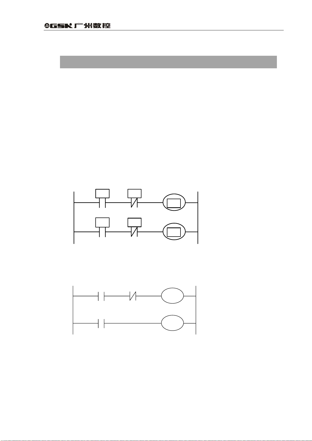
In general relay control circuit, each relay operates at approximately the same time, in the figure
below for example, when relay A operates, the relay D and E operate at approximately the same
time(when contacts B and C are off)., In PLC sequence control, each relay of circuit operates
sequentially. When relay A operates, relay D operates, then relay E operates (see the below figure).
Thus each relay operates in sequence which can be written as a ladder diagram. (programmed
sequence).
A
B
D
A
Fig. 2.1(a) circuit example
Fig.(b) and (c) illustrate operations varying from the relay circuit to PLC program.
A
A
Fig. 2.1(b)
C
E
C
B
C
5
Page 18

Programming Chapter Two Sequence Program
Fig. 2.1(c)
(1) Relay circuit
In Fig. (A) and (B), the operations are the same. Turning on A turns on B and C. Turning on C
turns off B.
(2) PLC program
In Fig. (B), as in the relay circuit, turning on A turns on B and C, and after one cycle of the PLC
sequence, turns off B. But in Fig.(C), turning on A turns on C, but does not turn on B.
2.2 Cycle execution
The PLC executes the ladder diagram from the beginning to the end . When the ladder diagram
ends, the program starts over from the beginning. This is called cycle execution.
The execution time from the beginning to the end of the ladder diagram is called the cycle
processing time. The shorter the process time is, the better the signal response becomes.
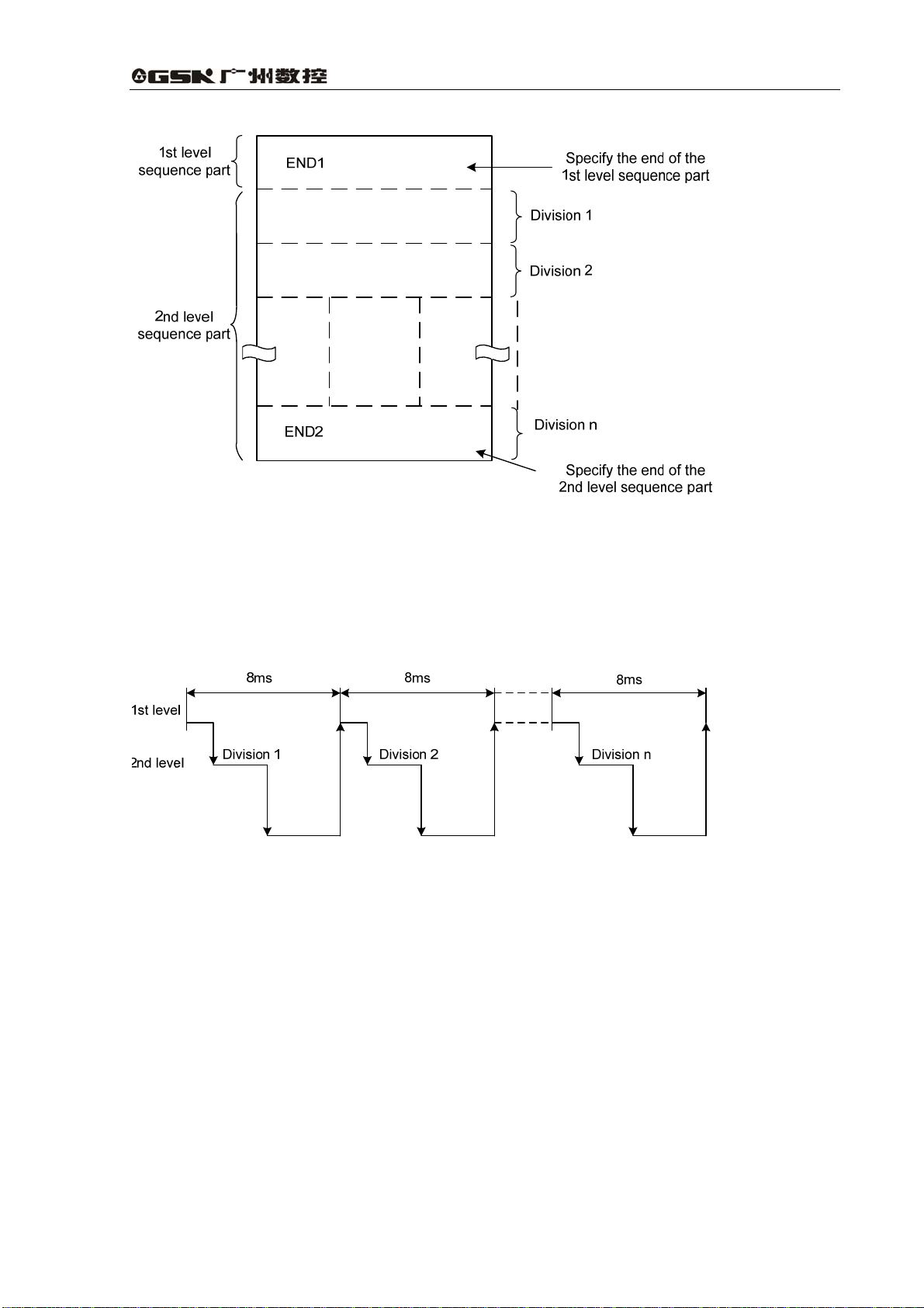
2.3 Priority of execution(1st level, and 2nd level)
GSK990MA PLC consists of two parts: 1st level sequence part, 2nd level sequence part. They have
different execution period.
st
The 1
high-speed response.
The 2
sequence part. The 2nd level sequence part is divided into n parts, and every part is executed every
8ms.
level sequence part operates every 8*n ms, which can deal with the short pulse signal with
nd
level sequence part operates every 8*n ms. Here n is a dividing number for the 2nd level
6
Page 19
GSK990MA CNC System Connection and PLC Manual
Fig. 2-3-1
990MA PLC is solely executed in PLC-AVR single chip, and the first 1ms of each 8ms is the
communication time of CNC reading or writing PLC data. The fifth 1ms is the time that the PLC
receives the system control signal (F、X)and uploads the control result data(G、Y parameter)
to the external I/O interface(X、Y), except for the time responding the interruption to exchange the
data, the PLC executes the ladder operation at the rest time.
Fig. 2-3-2
nd
After the last 2
level sequence part (division n) is executed, the sequence program is executed
again from the beginning. Thus, when the dividing number is n, the cycle of execution is 8*n ms.
st
The 1
of the 1
level sequence operates every 8ms, and the 2nd level sequence every 8*n ms. If the steps
st
level sequence is increased, the steps of the 2nd level sequence operating within 8ms
becomes less, thereby increasing the dividing number and making the processing time longer.
Therefore, it is desirable to program so as to reduce the 1st level sequence to a minimum.
2.4 Sequence program structure
With the conventional PLC, a ladder program is created sequentially. By employing a ladder
language that allows structured programming, the following benefits are as following :
7
Page 20
Programming Chapter Two Sequence Program
1. A program can be understood and developed easily
2. A program error can be found easily.
3.When an operation error occurs, the cause can be found easily.
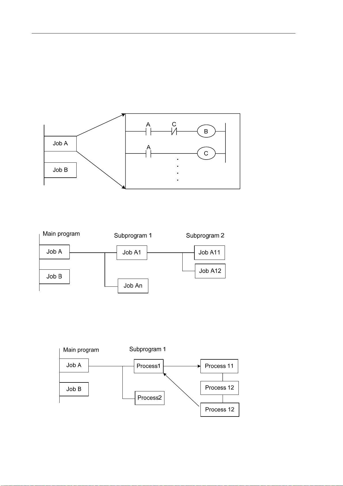
Three major structured programming capabilities are supported:
1) Subprogram
A subprogram can consist of a ladder sequence as the processing unit.
Fig. 2-4-1
2) Nesting
The Ladder subprograms can call the other ladder subprogram to execute the job.
Fig. 2-4-2
3) Conditional branch
The main program loops and checks whether conditions are satisfied. If a condition is satisfied, the
corresponding subprogram is executed. If the condition is not satisfied, the subprogram is skipped.
Fig. 2-4-3
8
Page 21
GSK990MA CNC System Connection and PLC Manual
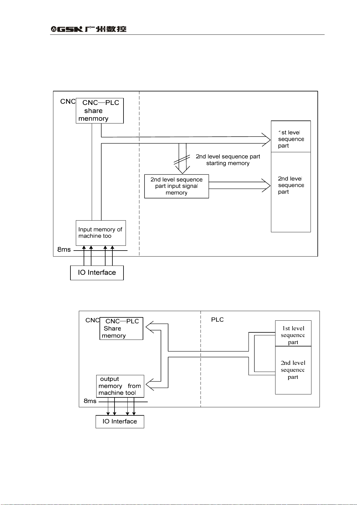
2.5 Processing I/O ( input / output ) signals
Input signal processing:
Output signal processi ng:
Fig. 2-5-1
Fig. 2-5-2
9
Page 22

Programming Chapter Two Sequence Program
2.5.1 Input signal processing
(1)NC input memory
The input signals from NC are loaded in memory of NC and are transferred to the PLC at intervals
of 8ms. Since the 1
(2)Input signal memory to machine tool
The input signal memory stores signals transferred from the machine tool at intervals of 8ms
period. Since the 1st level sequence part directly refer to these signal and process operations.
nd
(3)2
level input signal memory
The 2nd level input signal memory is also called 2nd level synchronous input signal memory. The
stored signals are processed by the 2
synchronizes with that of 2nd level sequence part.
Input memory Signals from NC and machine tool are transferred to the 2
memory only at the beginning of execution of the 2nd level sequence part. Therefore, the state of
nd
the 2
level synchronous input signal memory does not change from the beginning to end of the
execution of the 2nd level sequence part.
st
level sequence part directly refer to these signal and process operations.
nd
level sequence part. State of the signals set this memory
nd
level input signal
2.5.2 Output signal processing
(1)NC output memory
The output signals are transferred form the PLC to the NC output memory at intervals of 8ms.
(2)Output signals memory to machine tool
Signals stored in the machine tool output memory are transferred to the machine tool at intervals of
8ms.
Note:
The state of the NC input memory, NC output memory, input signals from machine, input/output
memory signals to machine can be checked by using the PC self-diagnosis function. The
self-diagnosis number specified is the address number used by the sequence program.
2.5.3 Difference state of signals between 1st level and 2nd level
The state of the same input signal may be different in the 1
Because they use different input memory. That is, at 1
signal memory and at 2nd level, processing is performed using the 2nd level synchronous input
nd
signal memory. Therefore, it is possible for a 2
level sequence execution at the worst, compared
with a 1st level input signal.
This must be kept in mind when writing the sequence program.
st
level and 2nd level sequences.
st
level, processing is performed using input
10
Page 23
GSK990MA CNC System Connection and PLC Manual
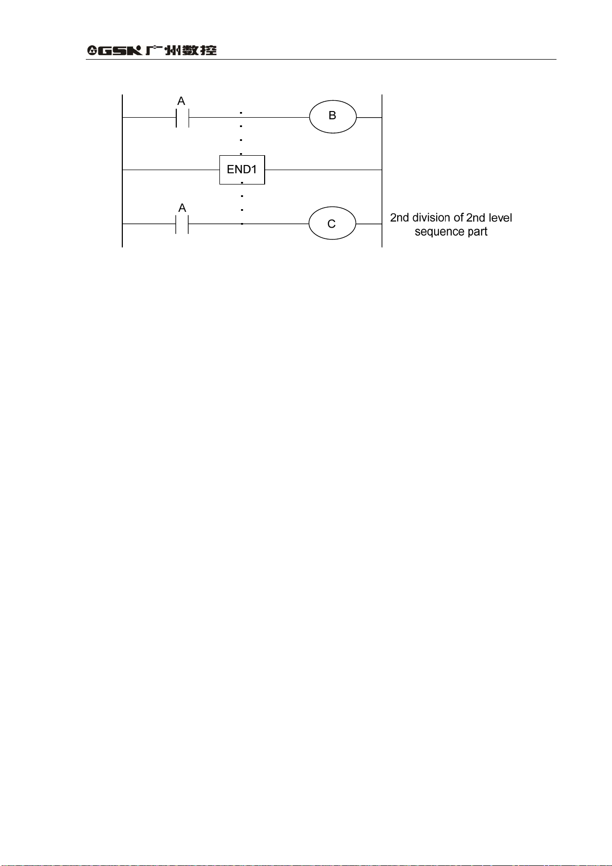
Fig. 2-5-3-1
When the processing is 1st 8ms, A=1, and B=1 after 1st sequence part is executed. At the same
time, 2nd sequence part is started to execute, A=1 is stored to the 2nd sequence part and the 1st
division of 2nd sequence part is executed.
When the processing is 2nd 8ms, A=0, and B=0 after 1st sequence part is executed. And then
2nd division of 2nd sequence part is executed, at this time, A is still 1. So C=1.
So, B and C are different.
2.6 Interlocking
Interlocking is important on sequence control safety.
Interlocking is necessary in the sequence control program. However, hard interlocking for the relay
circuit should be applied in the machine strong power cabinet. This is because even interlocking is
logically used in the sequence program (software), the interlock will not work when trouble occurs
in the hardware used to execute the sequence program. Therefore, provide an interlock inside the
machine tool magnetic cabinet to ensure the safety and to protect the machine from damage.
11
Page 24
Programming Chapter Three Address
3 Address
An address shows a signal location. Addresses include input/output signals with respect to the
machine, the input/output signals with respect to the CNC, the internal relays, the meters, the keep
relays, and data table. Each address consists of an address number and a bit number. Its serial
number regulations are as follows:
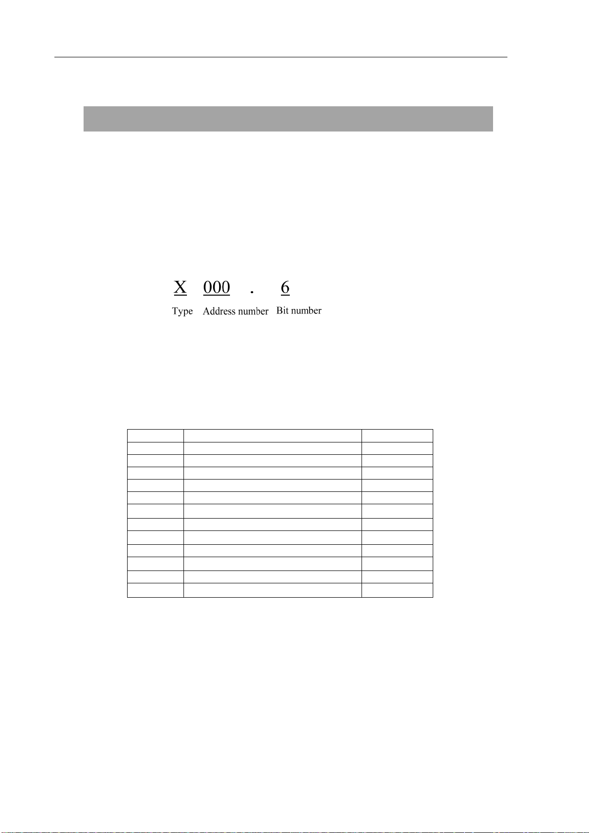
Address regulations:
The address comprises the address type, address number and the bit number in the format as
shown below:
Type: including X, Y, R, F, G K, A, D ,C, , T
Address number: decimal serial number stands for one byte.
Bit number: octal serial number, 0~7 stands for 0~7 bit of byte of front address number
990MA PLC address type is as follows:
Table 3-1
Address Signal description Length
X Machine tool → PLC(64 byte) INT8U
Y PLC→ Machine tool (48 byte) INT8U
F CNC→PLC(64 byte) INT8U
G PLC→CNC(64 byte) INT8U
R Auxiliary relay(512 byte) INT8U
D
DC Counter preset data register INT16U
C
A PLC message request signal INT8U
T
DT Timer preset data register INT16U
K
Data register (0~255)
Meter (0~127)
Timer (0~127)
Keep relay(64 byte)
INT16U
INT16U
INT16U
INT8U
INT8U data type is 8-bit character without signs, INT16U data type is 16-bit integer without signs.
3.1 Addresses from Machine tool to PLC(X)
X addresses of GSK990MA PLC are divided into two:
1. X addresses are assigned to IO input interface of XS43, XS44 and XS45.
2. X addresses are assigned to the input press keys on MDI panel.
12
Page 25

GSK990MA CNC System Connection and PLC Manual
3.1.1 Assignment of IO module X address
The addresses are from X0 to X5. Its type is INT8U, 48 types. They are assigned to three IO input
interface of XS 43, XS44 and XS45.
The signal specification of X addresses can be customized by customer according to the actual
operation. X addresses are used for machine (tool) connection and the ladder editing. For the
initial definition of input address, see Book 4 Connection of this manual.
3.1.2 Assignment of MDI panel X address
The addresses are from X20 to X30, 11 bytes. They correspond to the press keys on MDI panel,
and their signal definitions cannot be changed by user.
Corresponding relationship for addresses and press keys are as follows:
Table 3-1-2-1
Input key on operator panel PLC
address
Edit mode
Auto mode
MDI mode
Machine zero return mode
Single step mode
Manual mode
MPG mode
DNC mode
Skip
Single block
Dry run
Miscellaneous(M, S, T) lock
Machine lock
Optional stop
Program restart
Spindle CCW
Spindle stop
Spindle CW
Spindle negative override
Spindle override cancel
Spindle positive override
Spindle jog
Lubrication
Cooling
Chip removal
X20.0
X20.1
X20.2
X20.3
X20.4
X20.5
X20.6
X20.7
X21.0
X21.1
X21.2
X21.3
X21.4
X21.5
X21.6
X22.0
X22.1
X22.2
X22.3
X22.4
X22.5
X22.6
X23.0
X23.1
X23.2
Input key on operator panel PLC
address
Feedrate positive override
Feedrate override cancel
Feedrate negative override
Rapid
Rapid F0 / 0.001
Rapid 25% / 0.01
Rapid 50% / 0.1
Rapid 100% / 1
Manual feed axis +X
Manual feed axis +Y
Manual feed axis +Z
Manual feed axis +4TH
USER1
Manual feed axis -X
Manual feed axis -Y
Manual feed axis -Z
Manual feed axis -4TH
USER2
USER3
Spindle orientation
Tool magazine zero return
Tool clamp/ release
Tool magazine CW
Tool magazine CCW
tool infeed
X24.0
X24.1
X24.2
X24.7
X26.0
X26.1
X26.2
X26.3
X27.0
X27.1
X27.2
X27.3
X27.4
X28.0
X28.1
X28.2
X28.3
X28.4
X28.7
X29.0
X29.1
X29.2
X29.3
X29.4
X29.5
13
Page 26

Programming Chapter Three Address
Cycle start
Feed hold
X23.6
X23.7
tool retraction
Tool change manipulator
Overtravel release
X29.6
X29.7
X30.0
3.2 Address (Y) from PLC to machine tool
Y addresses of GSK990MA PLC are divided into two:
1. Y addresses are assigned to IO input interface of XS40, XS41 and XS42.
2. Y addresses are assigned to the indicators on MDI panel.
3.2.1 Assignment of IO module Y address
The addresses are from Y0 to Y5. Its type is INT8U, 48 types. They are assigned to three IO output
interfaces of XS40, XS41 and XS42.
The signal specification of Y addresses can be customized by customer according to the actual
operation. Y addresses are used for machine tool connection and the ladder editing. For the initial
definition of input address, see Appendix one Allocation and definition of PLC IO address, auxiliary
relay and register for GSK990MA CNC system
3.2.2 Assignment of IO module Y address
The addresses are from Y12 to Y19, 8 bytes. They correspond to the indicators on MDI panel, and
their signal definitions cannot be changed by user.
Corresponding relationship for addresses and indicators are as follows:
Table 3-2-2-1
Output key on operator panel PLC
address
Edit key indicator Y12.0 0.01/25% indicator Y15.4
Auto key indicator Y12.1 0.1/50% indicator Y15.5
MDI key indicator Y12.2 1/100% indicator Y15.6
Machine zero return indicator Y12.3 Spindle orientation indicator Y15.7
Single step key indicator Y12.4 Tool magazine zero return
Manual key indicator Y12.5 Tool magazine CCW indicator Y16.1
MPG key indicator Y12.6 Tool magazine CW indicator Y16.2
DNC key indicator Y12.7 Tool magazine infeed indicator Y16.3
Spindle CCW indicator Y13.0 Tool magazine retraction
Spindle CW indicator Y13.1 Tool magazine clamp indicator Y16.5
Spindle override cancel
indicator
Y13.2 Tool change manipulator
Output key on operator panel PLC
address
Y16.0
indicator
Y16.4
indicator
Y16.6
indicator
14
Page 27

GSK990MA CNC System Connection and PLC Manual
X machine zero return
indicator
Y machine zero return
indicator
Z machine zero return
indicator
4TH machine zero indicator Y13.6 +Z indicator Y17.2
Optional stop indicator Y13.7 +4TH indicator Y17.3
Skip indicator Y14.0 USER1 indicator Y17.4
Single block indicator Y14.1 -X indicator Y18.0
Dry run indicator Y14.2 -Y indicator Y18.1
Miscellaneous(M, S, T) lock
indicator
Y13.3
Y13.4 +X indicator Y17.0
Y13.5 +Y indicator Y17.1
Y14.3 -A indicator Y18.2
USER3(tool change position)
indicator
3.3 Address (G) from PLC to CNC
Addresses are from G0 to G63. Type: INT8U, 64 bytes.
Key signals on the operator panel
Table 3-3-1
Y16.7
Key signal on operator
panel
Edit mode
Auto mode G20.1 Rapid F0
MDI mode G20.2 Rapid 25%
Machine zero return mode
Single step mode
Manual mode
MPG mode G20.6 Incremental step 0.01 G261
DNC mode G20.7 Incremental step 0.1
Skip
Single block
Dry run
Miscellaneous (M,S, T) lock
Machine tool lock
Selection stop G21.5 Manual feed axis +Y
Program restart G21.6 Manual feed axis +Z
Spindle CW
Spindle stop
Spindle CCW G22.2 Manual feed axis -Y
Spindle negative override G22.3 Manual feed axis -Z
Spindle override cancel
PLC
address
G20.0
G20.3
G20.4
G20.5
G21.0
G21.1
G21.2
G21.3
G21.4
G22.0
G22.1
G22.4
Key signal on operator panel PLC
address
Rapid switch G24.7
G25.0
G25.1
Rapid 50%
Rapid 100%
Incremental step 0.001 G26.0
Incremental step 1
MPG step 0.001
MPG step 0.01
MPG step 0.1
Manual feed axis +X
Manual feed axis +4TH
Manual feed axis -X G28.0
Manual feed axis -4TH
G25.2
G25.3
G26.2
G26.3
G26.4
G26.5
G26.6
G27.0
G27.1
G27.2
G27.3
G28.1
G28.2
G28.3
15
Page 28
Programming Chapter Three Address
Spindle positive override
Spindle jog
The bit signals of G63 bytes are internally used by the system, G63.0, G63.1 and G63.2 are
separately the system internal response signals for M, S, T code completion.
G22.5
G22.6
Spindle orientation
Tool magazine zero return
G29.0
G29.1
3.4 Address (F) from CNC to PLC
Addresses are from F0 to F63. Type: INT8U, 64 bytes.
For signals, see Volume Function.
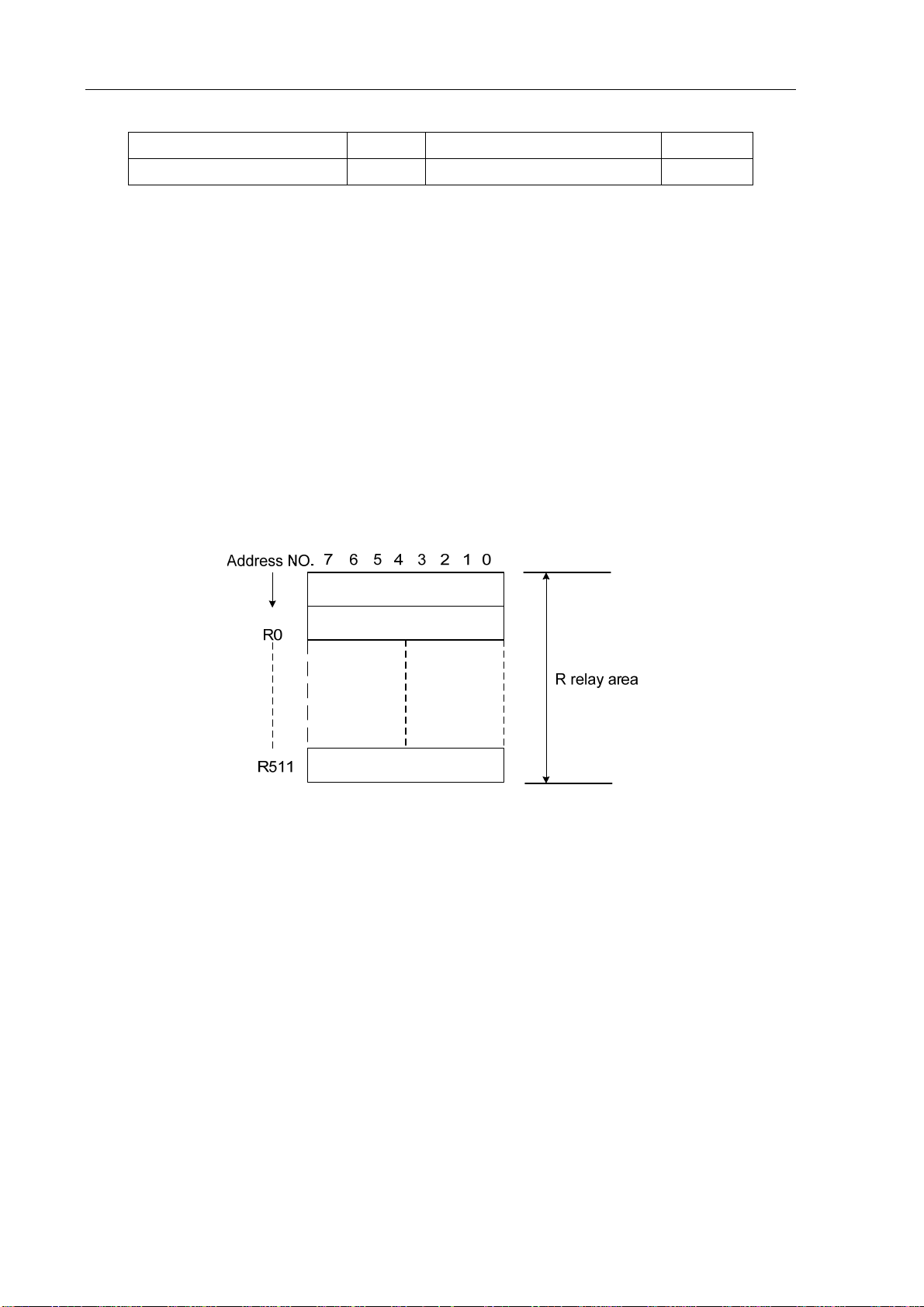
3.5 Internal relay address(R)
The address area is cleared to zero when the power is turned on. R510 and R511 are used by the
system.
Type: INT8U, 512 bytes.
Fig. 3-5-1
System program management area:
R510
Address signal of R510.0 is set to 1 when PLC is started or restarted, which is used for the
signal set by user in initialization. It is set to 0 after the ladder finishing the first pass.
R511(timer for system)
The following four signals are used as system timer:
16
Page 29
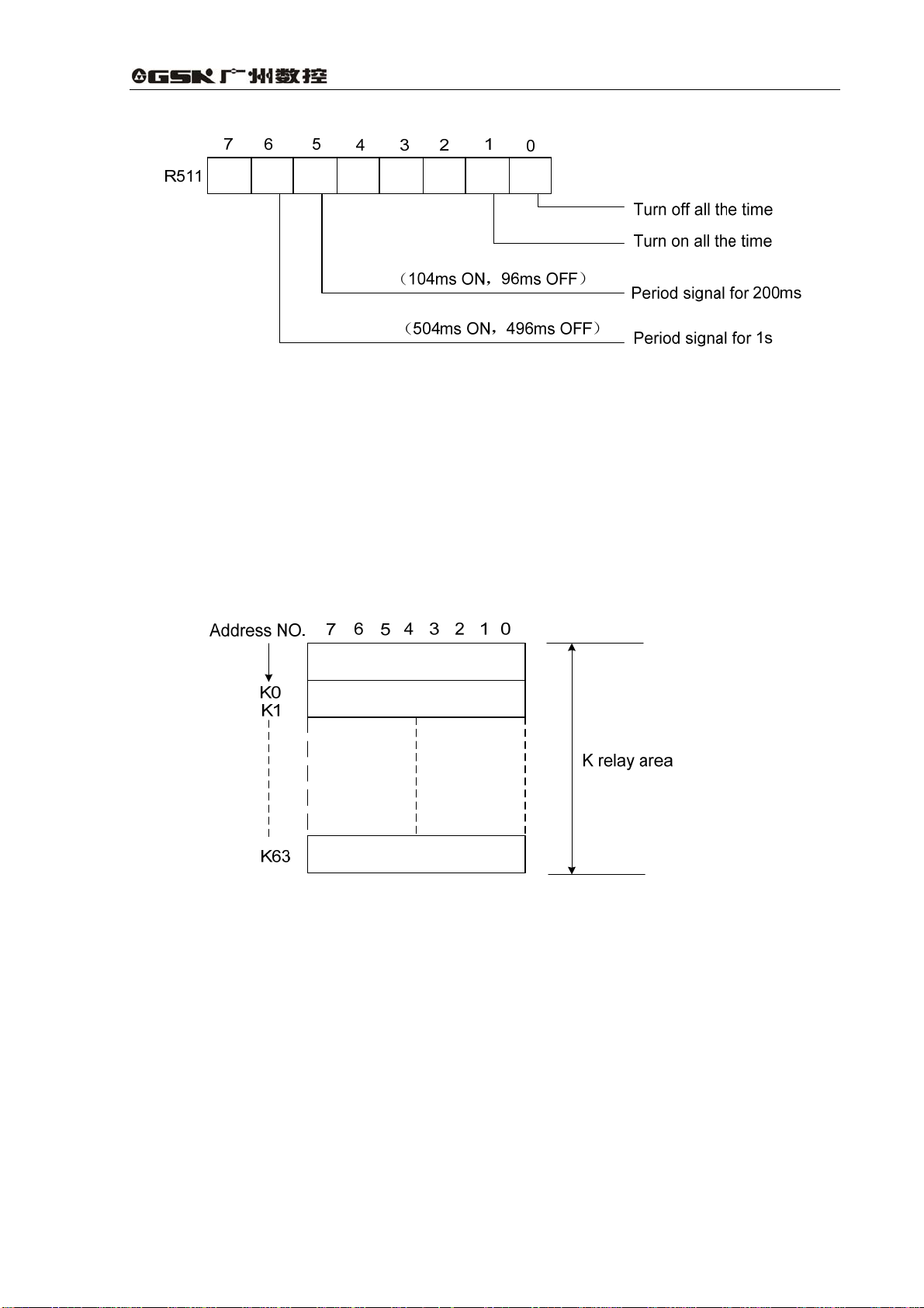
GSK990MA CNC System Connection and PLC Manual
Fig. 3-5-2
3.6 Address of keep relay(K)
The area is used as keep relays and PLC parameters. Since this area is nonvolatile, the content of
the memory do not disappear even when the power is turned off. K000~~K005 are used by the
system, which are used for storing the PLC system parameter. It is convenient for the user to
control the PLC by CNC.
Type: INT8U, with 64 bytes.
Fig. 3-6-1
Note: When PLC address K K005.2=1, PLC enters the debug mode, cancel all the external alarm
signals and machine interlock signals, the tool change instruction can’t be executed. The
parameter can be modified under fully understanding it to avoid the machine damage or
the person accidence.
3.7 Addresses(A) for message selection displayed on CRT
The address area is cleared to zero when the power is turned on.
Type: INT8U, with 32 bytes.
17
Page 30

Programming Chapter Three Address
Fig. 3-7-1
3.8 Address of meter(C)
The area is used as storing current counting value in meter. The address area is cleared to zero
when the power is turned on.
Type: 128 addresses.
3.9 Meter preset address(DC)
The address area is used to store the meter preset value. Since this area is nonvolatile, the
content of the memory do not disappear even when the power is turned off.
Type: 128 addresses.
3.10 Timer addresses(T)
The area is used as storing current counting value in timer. The initial data is the preset value
when the system is turned off. When preset value is 0, the current data is preset value.
Type: 128 addresses.
3.11 Addresses of timer preset value(DT)
The address area is used as storing preset value. Since this area is nonvolatile, the content of the
memory do not disappear even when the power is turned off.
Type: 128 addresses.
18
Page 31

GSK990MA CNC System Connection and PLC Manual
3.12 Address of data table(D)
The content of the memory do not disappear even when the power is turned off.
Type: 256 addresses.D240~247 are used by the system and cannot be defined by the user.
3.13 Label address(L)
Label addresses are used to specify jump destination labels and LBL labels in JMPB instructions.
Range: 0~99
3.14 Subprogram numbers(P)
Subprogram numbers are used to specify jump destination subprogram labels and SP instruction
subprogram labels in CALL instruction.
Range: 0~99
19
Page 32

Programming Chapter Four PLC Basic Instruction
4 PLC Basic Instruction
Designing a sequence program begins with creating a ladder diagram. The ladder diagram is
written using relay contact symbols and functional instruction code. Logic written in the ladder
diagram is entered as a sequence program in the Programmer. There are two sequence program
entry methods. One is the entry method with the mnemonic language (PLC instructions such as
RD, AND, OR but currently the system does not support it). The other is the relay symbols of the
ladder diagram. When the relay symbol method is used, the ladder diagram format can be used
and programming can be performed without understanding the PLC instruction format.
Actually, however, the sequence program entered by the relay symbol method is also internally
converted into the instruction corresponding to the PLC instruction.
The basic instructions are often used when the sequence program is designed, and they execute
one-bit operation.
GSK990MA basic instructions are as follows:
Table 4-1
Instruction Function
RD Shifts left the content by one bit in register and sets the state of a
specified signal in ST0.
RD.NOT Shifts left the content by one bit in register and sets the logic state
of a specified signal in ST0.
WRT Outputs the results of logic operation to a specified address.
WRT.NOT Inverts the results of logical operations and output it to a specified
address.
AND Induces a logical product.
AND.NOT Inverts the state of a specified signal and induces a logical
product.
OR Induces a logical sum.
OR.NOT Inverts the state of a specified signal and induces a logical sum.
OR.STK Sets the logical sum of ST0 and ST1, and shifts the stack register
right by one bit.
AND.STK Sets the logical product of ST0 and ST1, and shifts the stack
register right by one bit.
20
Page 33

GSK990MA CNC System Connection and PLC Manual
4.1 RD, RD.NOT, WRT, WRT.NOT
Instructions and functions
Table 4-1-1
Instruction Function
RD
RD.NOT
WRT
WRT.NOT
Instruction explanation:
z WRT, WRT. NOT are the output relays, internal relay instructions. They cannot be used for
input relay.
z The parallel WRT instruction can be continuously used many times, but double-coil output
is disabled.
Programming:
Shifts left the content by one bit in register and sets the state of a
specified signal in ST0.
Shifts left the content by one bit in register and sets the logic state of
a specified signal in ST0.
Outputs the results of logic operation to a specified address.
Inverts the results of logical operations and output it to a specified
address.
Fig. 4-1
4.2 AND, AND.NOT instructions
Instructions and functions
Table 4-2-1
Instruction Function
AND Induces a logical product.
AND.NOT
21
Inverts the state of a specified signal
and induces a logical product.
Page 34

Programming Chapter Four PLC Basic Instruction
Instruction explanation:
z AND, AND NOT can connect with one contact in serial. The serial contact numbers are not
limited and they can be used many times.
Programming
Fig. 4-2-1
4.3 OR, OR.NOT instructions
Instructions and functions
Table 4-3-1
Instruction Function
OR Induces a logical sum.
OR.NOT Inverts the state of a specified signal
and induces a logical sum.
Instruction specification:
z OR, OR_NOT can connect with one contact in parallel.
z OR, OR.NOT begins from their step, which can connect with the RD,RD.NOT instructions
step mentioned before in parallel.
Programming:
Fig. 4-3-1
4.4 OR. STK instruction
Instruction and function:
22
Page 35

GSK990MA CNC System Connection and PLC Manual
Table 4-4-1
Instruction Function
OR. STK Sets the logical sum of ST0 and ST1, and shifts the
stack register right by one bit.
Instruction specification:
z OR.STK a sole instruction without other address.
Programming
Fig. 4-4-1
As the above figure, there are three branch circuit ①,②, from left bus to the node N1, among ③
which ①, is circuit block② in series; when there is the serial circuit block in the parallel from the
bus to node or between nodes, the following branch end uses RD instruction except for the first
branch. The branch is not serial circuit block to use OR instruction. ③
OR.STK and AND.STK are instructions without operation components, indicating the OR, AND
relationship between circuit blocks.
4.5 AND.STK instruction
Instruction and function
Table 4-4-1
Instruction Function
AND.STK Sets the logical product of ST0 and ST1, and shifts the
stack register right by one bit.
Instruction specification
z When the branch loop (parallel loop block) is connected to the previous loop in series, use
AND.STK instruction. The starting point of branch uses RD, RD.NOT instruction, after the
parallel loop block ends, AND,STK instruction is connected to previous loop in series.
z AND.STK a sole instruction without other address.
23
Page 36

Programming Chapter Four PLC Basic Instruction
Programming
RD X002.1
OR.NOT F100.3
OR.NOT X011.0
RD R100.0
AND.NOT R100.3
RD G003.3
AND R009.7
OR.STK ← ⑴
AND.STK ← ⑵
WRT Y003.7
As the above figure and instruction list, ⑴ RD reports the circuit block in series is connected
parallel AND.STK ⑵ reports the block and are connected in series. ①②
Block ①
Block ②
Fig. 4-5-1
24
Page 37

GSK990MA CNC System Connection and PLC Manual
5 PLC Functional instructions
If basic instructions such as controlling operations of machine tool are difficult to program,
functional instructions are available to facilitate programming.
Table 5-1(990MA PLC functional instruction code)
No. Instruction Processing
1 END1
2 END2
3 CALL
4 CALLU
5 SP
6 SPE
7 SET
8 RST
9 JMPB
10 LBL
11 TM R
12 TMRB
13 TMRC
14 CTR
15 DEC
End of a first-level ladder program
End of a second-level ladder program
Calling subprogram
Subprogram
End of subprogram
Set
Reset
Label jump
Label
Timer
Fixed Timer
Timer
Binary meter
Binary decoding
16 COD
17 COM
18 COME
19 ROT
20 SFT
21 DIFU
22 DIFD
23 COMP
24 COIN
25 MOVN
25
Binary code conversion
Common line control
End of common line control
Binary rotation control
Register shift
Rising edge check
Failing edge check
Binary comparison
Coincidence check
Data transfer
Page 38

Programming Chapter Five PLC Functional Instructions
26 MOVB
27 MOVW
28 XMOV
29 DSCH
30 ADD
31 SUB
32 ANDF
33 ORF
34 NOT
35 EOR
Transfer of an arbitrary number of bytes
Transfer of two arbitrary number of bytes
Binary Indexed data transfer
Binary data search
Binary addition
Binary subtraction
Functional AND
Functional OR
Logical Negation
Exclusive OR
5.1 END1(1st level sequence program end)
Function:
It must be specified once in a sequence program, either at the end of the 1st level sequence, or at
the beginning of the 2
at most.
Format:
nd
level sequence when there is no 1st level sequence. It can write 500 steps
Fig. 5-1-1
5.2 END2(2nd level sequence program end)
Function
It is specified at the end of 2nd level sequence.
Format:
Fig. 5-2-1
26
Page 39

GSK990MA CNC System Connection and PLC Manual
5.3 CALL(call subprogram)
Function
Call a specified subprogram.
CALL has the following features and restrictions:
The subprogram may be nested up to 18 levels by other subprograms, but if a dead cycle is
made by the closed loop calling, an alarm will be issued by system. Therefore to execute the
data volume under the control, the allowable subprogram calling times are 100, and the
subprogram calling in the 1st level is disabled. Alarm will be issued for the instructions or network
between SP and END2, SPE and SP which can't be executed by system.
Format:
Fig. 5-3-1
Control condition:
ACT=0,execute the next instruction behind CALL.
ACT=1,call subprogram which number is specified.
Parameter:
Subprogram number.: specifies the number of a subprogram to be called.
Range: 0~99.
5.4 CALLU(unconditional subprogram call)
Function:
Call a specified subprogram without condition.
CALL has the following features and restrictions:
The subprogram may be nested up to 18 levels by other subprograms, but if a dead cycle is
made by the closed loop calling, an alarm will be issued by system. Therefore to execute the data
volume under the control, the allowable subprogram calling times are 100, and the subprogram
calling in the 1st level is disabled. Alarm will be issued for the instructions or network between SP
27
Page 40

Programming Chapter Five PLC Functional Instructions
and END2, SPE and SP which can't be executed by system
Format:
Fig. 5-4-1
Parameter:
Subprogram number:specifies the number of a subprogram to be called. Range:0~99.
5.5 SP(Subprogram)
Function:
The SP functional instruction is used to create a subprogram. A subprogram number is specified
as a subprogram name. SP is used with the SPE functional instruction to specify the subprogram
range.
Note:
1. A subprogram must be written after END2.
2. Another subprogram cannot be nested into a subprogram.
Format:
Fig. 5-5-1
Parameter:
Subprogram number: specifies the subprogram number of a subprogram to be called.
Range: 0~99.
5.6 SPE(subprogram end)
Function:
* it is used to specify the range of subprogram when SPE is used with the S P.
* the control will return to the main program which called the subprogram when the
instruction is executed.
* the subprogram must be written after END2.
28
Page 41

Format:
GSK990MA CNC System Connection and PLC Manual
Example:
5.7 SET(set)
Fig. 5-6-1
Fig. 5-6-1
Function:
Set to 1 for the specified address.
Format:
ACT
SET
Control condition:
ACT=0,add.b keep invariably.
ACT=1,add.b set to1.
Parameter:
Add.b:set element address bit can be the output coil, Add= Y,G,R,K,A.
Add.b
Fig. 5-7-1
address
29
Page 42

Programming Chapter Five PLC Functional Instructions
5.8 RST(reset)
Function:
Set to 0 for the specified address.
Format:
Fig.5-8-1
Control condition:
ACT=0,add.b keep invariably.
ACT=1,add.b set to1.
Parameter:
Add.b:reset element address bit can be the output coil, Add= Y,G,R,K,A.
5.9 JMPB(label jump)
Function:
The JUMP functional instruction transfer control to a Ladder immediately after the lable set in a
Ladder program.
JMPB has the following features and restrictions:
* More than one jump instruction can be coded for the same label.
* Jump between 1
* Jump between subprograms is forbidden.
* Jump back is permitted, but the user should handle the endless loop may be
caused by it .
* Jump between main program and subprogram is forbidden.
Format:
st
level program and 2nd level is forbidden.
Control conditions:
30
Fig. 5-9-1
Page 43

GSK990MA CNC System Connection and PLC Manual
ACT=0: The next instruction after the JMPB instruction is executed.
ACT=1: Control is transferred to the Ladder immediately after the specified label.
Parameter:
Lx: specifies the label of the jump destination. A value from 0 to 99 can be specified.
5.10 LBL(Label)
Function:
The LBL functional instruction specifies a label in a ladder program. It specifies the jump
destination for JMPB functional instruction.
Note: one Lx label is only specified one time with LBL. Otherwise, the system alarms.
Format:
Fig. 5-10-1
Parameter:
Lx: specifies the label of the jump destination. Label number range: 0~99
Example:
JMPB 33
LBL 33
JMPB 33
Fig. 5-10-2
31
Page 44

Programming Chapter Five PLC Functional Instructions
5.11 TMR(timer)
Function:
This is an on-delay timer.
Format:
Fig. 5-11-1
Control condition:
ACT=0: turns off the timer relay.
ACT=1: initiates the timer.
Detailed functions:
Parameter:
TIMER :timer serial number is named with xxx which are numbers (0~127).
Output:
W : output coil. W=1 when the output reaches the preset value. W=0 when the output
does not reach the preset value.
Note:
Timer is executed each 8ms, take ms as its setting unit, and 8ms is taken as the execution
base. Those time less than 8ms are taken as 8ms. i.e. it is set for 54ms, 54=6*8+6, 2ms is
needed to be added, so the actual execution time is 56ms.
Fig. 5-11-2
The time of the timer is set under the 【TMR】of 【PLCPAR】in PRG interface.
The system will automatically detect the range of the sequence number of the timer, alarm
will be issued for those duplicate or beyond range sequence numbers.
32
Page 45

GSK990MA CNC System Connection and PLC Manual
5.12 TMRB(fixed timer)
Function:
This is an on-delay timer.
Format:
Fig. 5-12-1
Control condition:
ACT=0: turns off the timer.
ACT=1: initiates the timer.
Detailed functions:
Fig. 5-12-2
Parameter:
TIMER :fixed timer serial number is named with xxx which are numbers (0~127).
Table 5-12-1(timer precision)
Timer precision Setting number Setting time range Error range
8msec 0 From 8msec to
524.280sec
48msec 1 From 48msec to
31.456 min
1sec 2 From 1sec to
546 min
10sec 3 From 10sec to
182 h
1min 4 From 1min to
From 0 to scan period
for1st level program
From 0 to scan period
for1st level program
From 0 to scan period
for1st level program
From 0 to scan period
for1st level program
From 0 to 1sec
1092 h
1msec 5 From 1msec to
65.4sec
From 0 to scan period
for1st level program
33
Page 46

Programming Chapter Five PLC Functional Instructions
Preset time:
Fixed timer timing setting, range (0~65535).
Output:
W : output coil. W=1 when the output reaches the preset value. W=0 when the output does not
reach the preset value.
Note:
The system will automatically detect the range of the sequence number of the timer, alarm
will be issued for those duplicate or beyond range sequence numbers.
The preset time of the timer will be fixed in ROM with the ladder, therefore, the time can be
changed only by altering the ladder.
5.13 TMRC(timer)
Function:
This is an on-delay timer.
Format:
Control condition:
ACT=0: turns off the timer.
ACT=1: initiates the timer.
Detailed functions:
Fig. 5-13-1
Fig. 5-13-2
34
Page 47

GSK990MA CNC System Connection and PLC Manual
Parameter:
TIMER :timer serial number is named with xxx which are numbers (0~127).
Table 5-12-1(timer precision)
Timer precision Setting number Setting time range Error range
8msec 0
48msec 1
1sec 2
10sec
3 From 10sec to 182 h
From 8msec to
524.280sec
From 48msec to
31.456 min
From 1sec to
546 min
From 0 to scan period
for1st level program
From 0 to scan period
for1st level program
From 0 to scan period
for1st level program
From 0 to scan period
for1st level program
1min
1msec
Output:
4 From 1min to 1092 h From 0 to 1sec
5 From 1msec to
65.4sec
From 0 to scan period
for1st level program
W : output coil. W=1 when the output reaches the preset value. W=0 when the output does not
reach the preset value.
Note:
The time can be set via 【TMR】in 【PLCPAR】of PLC windowns.
TMRC timer and TMR timer use a same address, therefore, their sequence number
cannot be the same.
The system will automatically detect the range of the sequence number of the timer,
alarm will be issued for those duplicate or beyond range sequence numbers.
5.14 CTR(binary counter)
Function:
The data in the counter are binary and their functions are as follows:
1) Preset counter
Preset the count. It outputs a signal when the preset count is reached.
2) Ring counter
If the counter reaches the preset value, input the count signal to restore the initial value and
recount.
3) Up/down counter
35
Page 48

Programming Chapter Five PLC Functional Instructions
The count can be either up or down.
4) Selection of initial value
Its initial value is 0 or 1.
Format:
Control condition:
Specifies the initial value(CN0):
CN0=0: begins the value of the counter with 0.
CN0=1 begins the value of the counter with 1.
Specify up or down counter (UPDOWN):
UPDOWN=1: Up counter
UPDOWN=0: Down counter
Reset (RST):
RST=0: release reset.
RST=1: enable reset. When W=0, the integrated value is reset to the initial value.
Count signal(ACT):
Fig. 5-14-1
RST is set to 1 only when reset is required.
Parameter:
METER:specifies the counter serial number with xxx which are numbers (0~127).
36
ACT=1:count is made by catching the rise of ACT.
ACT=0:counter does not operate. W does not change.
Page 49

GSK990MA CNC System Connection and PLC Manual
Output:
W:coil output. W=1 when the counter reaches the preset value.
Note: The system will automatically detect the range of the sequence number of the counter, alarm
will be issued for those duplicate or beyond range sequence numbers.
It needs to reset again after setting the preset value again to ensure the instruction
reliability.
5.15 DEC(binary decode)
Function:
DEC can decode binary code data. Outputs 1 when the eight-digit BCD signal is equal to a
specified number, and 0 when not.
It is mainly used to decode M or T function.
Format:
Fig. 5-15-1
Control condition:
ACT=0 : resets all the output data bit.
ACT=1 : decode data. Results of processing is set in the output data address.
Parameter:
length : Set the size of code data to the 1
st
digit of the parameter.
0001:code data is in binary format of 1 byte length.
0002:code data is in binary format of 2 byte length.
S1 : code data address. Specifies an address at which code data is stored.
S2 : number specification decode designation. Specifies the first of the 8
continuous numbers to be decoded.
S3 : decode result address. Specifies an address where the decoded
result shall be output. A one-byte area is necessary in the memory for
the output.
37
Page 50

Programming Chapter Five PLC Functional Instructions
Example:
When ACT=1 and F10=8, R4=0000,0001;
When ACT=1 and F10=9, R4=0000,0010;
………… ……………….
When ACT=1 and F10=15, R4=1000,0000;
5.16 COD(binary code conversion)
Function:
Format:
COD instruction automatically creates a table with corresponding size used for user
inputting conversion table data when it inputs the data capacity. Each table has 10
lattices and if it is not divided by 10, count the lattices by its quotient adding 1, but its
capacity data does not change and the address of table number will not be displayed.
Fig. 5-16-1
Control conditions:
Reset (RST):
RST=0: do not reset.
38
Fig. 5-16-2
Page 51

GSK990MA CNC System Connection and PLC Manual
RST=1: reset error output W.
Activate instruction (ACT):
ACT=0 : do not execute COD.
ACT=1 : execute COD. Take value of “Conversion input data address(S1)” as
the table number of conversion table, take out of 1 conversion data
which corresponds to the table number from the conversion table,
output the output address used for the conversion data (S2).
Fig. 5-16-2
Parameter:
Length1 :Designates binary numerical size in the conversion table.
1:Numerical data is binary 1-byte data.
2:Numerical data is binary 2-byte data.
length2 : Number of conversion table data. 100 data can be made at most. 100 bytes
when designating 1 byte format, and 100 words when 2 byte format. All
number is at most 512 bytes in COD conversion table.
S1 : Data in the conversion data table can be taken out by specifying the table number.
The address specifying the table number is called conversion input data address,
and 1-byte memory is required from the specified address.
S2 :Conversion data output address. Memory of the byte length specified in the format
designation is necessary from the specified address.
Output:
If there are any abnormality when executing the CODB instruction, W=1, and error will be
output.
39
Page 52

Programming Chapter Five PLC Functional Instructions
Note: Size of the conversion data table is maximum 256. This conversion data table is
programmed between the parameter conversion data output address of this
instruction and the error output (W).
5.17 COM (common line control)
Function:
This function can be used for specifying the number of coil only on the PLC-SB/SC. If the
common line end instruction is not specified, the system will alarm.
Format:
Control condition:
ACT=0: The specified number of coils or the coils within the region specified are
unconditionally turned off (W=0).
ACT=1: No processing is performed.
Note:
1. In the range specified with a COM instruction, no additional COM instruction can be
specified.
2. The coil for WRT.NOT in the range specified with a COM instruction is singly set to 1 when
COM ACT=0.
3. do not use the function instructions such as JMPB、END1、END2、CALL、CALLU、LBL、
SP、SPE、COM、COME between COM and COME, otherwise, the system will alarm.
5.18 COME (common line control end)
Function:
The instruction specifies the control range of the common line control instruction (COM). It cannot
be used alone. It must be used together with the COM instruction.
40
Page 53

GSK990MA CNC System Connection and PLC Manual
Format:
Fig. 5-18-1
5.19 ROT(Binary rotation control)
Function:
Controls rotors, such as the toolpost, rotary table, etc., and is used for the following functions.
1. Selection of the rotation direction via the shorter path.
2. Calculation of the number of steps between the current position and the goal position;
calculation of the position on position before the goal to the number of steps up to one
position before the goal.
3. Calculation of the position one position before the goal or of the number of steps up to one
position before the goal.
Format:
Fig. 5-19-1
Control conditions:
Specify the starting number of the rotor(CN0):
CNO=0: begins the number of the position of the rotor with 0.
CNO=1: begins the number of the position of the rotor with 1.
41
Page 54

Programming Chapter Five PLC Functional Instructions
Select the rotation direction via the shorter path or not: (DIR):
DIR=0: no direction is selected. The direction of rotation is only forward.
DIR=1: selected. The direction of rotation is forward/backward.
Specify the operation conditions (POS):
POS=0: calculate the goal position.
POS=1: calculates the position one position before the goal position.
Specify the position or the number of steps (INC):
INC=0: calculates the number of the position. If the position one position before
the goal position is to be calculated, specify INC=0 and POS=1.
INC=1: calculates the number of steps. If the difference between the current
position and the goal position is to be calculated, specify INC=1 and
POS=0.
Execution instruction (ACT):
ACT= 0:the ROT instruction is not executed. W does not change.
ACT=1:executed. Normally, set ACT=0. If the operation results are required,
set ACT=1.
Parameter:
S1 : specify the rotor indexing number.
S2 : specify the address storing the current position.
S3 : specify the address storing the goal position(or instruction value), for example the
address storing the CNC output T code.
S4 : calculate the number of steps for the rotor to rotate, the number of steps up to
the position one position before, or the position before the goal. When the
calculating result is to be used, always check that ACT=1.
Output:
W: The direction of rotation for control of rotation via the shorter path is output to W. When
W=0, the direction is forward (FOR) , when 1, reverse (REV). The definition of FOR and
REV is shown in the following figure. If the number given to the rotor is ascending, the
rotation is FOR; if descending, REV. The address of W can be determined arbitrarily.
When, however, the result of W is to be used, always check that ACT=1.
Example:
Rotor rotation direction:
42
Page 55

GSK990MA CNC System Connection and PLC Manual
Fig. 5-19-2
Fig. 5-19-3
Perform the short path rotation, and calculate the position number of previous one position of goal
position.
Current position number S2=1, position number of rotation graduation S1=12,CNO=1,DIR=1
POS=1,INC=0:
When S3=10 goal position is A, and ACT=1, S4=11,W=1.
When S3=8 goal position is B, and ACT=1, S4=9, W=1.
When S3=5 goal position is C, and ACT=1, S4=4, W=0.
When S3=3 goal position is D, and ACT=1, S4=2, W=0.
43
Page 56

Programming Chapter Five PLC Functional Instructions
5.20 SFT(shift register)
Function:
This instruction can each time shift a byte data (8 bits) by a bit number set by a Parameter, For the
circular shifting, each overflowing "1" will be added reversely, i.e. If the highest bit "1" is overflowed
by the left shifting, the lowest bit will be filled by "1", vice versa.
Format:
Fig. 5-20-1
Control conditions:
Shift direction specification (DIR)
DIR=0: Left shift
DIR=1: Right shift
Condition specification (CONT)
CONT=0: do not cycle shift
CONT=1: cycle shift
Reset(RST)
The shifted out data(W=1) is reset (W=0).
RST=0: W is not reset.
RST=1: W is reset (W=0).
Actuation condition (ACT)
ACT=0: do not execute SFT instruction.
ACT=1: execute shifting. If shifting one bit only, set ACT to 0 after finishing the
44
Page 57

GSK990MA CNC System Connection and PLC Manual
execution.
Parameters:
S1 :sets shift data addresses. These designated addresses require a continuous 1-byte
memory for shift data.
Length :a 4-bit number, and its definition is as follows:
Fig. 5-20-2
L :range: 0~8.
A :bit parameter. A=0: When ACT=1 is shifting, the shift period is one bit.
A=1: ACT is taken as pulse signal, it is 1 from 0, shift one
bit.
Output:
W : W=0: “1” was not shifted out because of the shift operation.
W=1: “1” was shifted out because of the shift operation.
5.21 DIFU(rising edge check)
Function:
The DIFU instruction sets the output signal to 1 for one scanning cycle on a rising edge of the
input signal.
Format:
Fig. 5-21-1
Control condition:
Input signal: On a rising edge(01)of the input signal, the output signal is set to 1.
Output signal: The output signal level remains at 1 for one scanning cycle of the ladder when
this functional instruction is operating.
45
Page 58

Programming Chapter Five PLC Functional Instructions
Parameter:
L :rising edge number, range 0~255. If another DIFU instruction or DIFD instruction in the
ladder uses the same number, the system will alarm.
Operation:
Fig. 5-21-1
5.22 DIFD(falling edge check)
Function:
The DIFD instruction set the output signal to 1 for one scanning period on a falling edge of the
input signal.
Format:
Fig. 5-22-1
Control conditions:
Input signal: on a falling edge(10)of the input signal, the output signal is set to 1.
Output signal: the output signal level remains at 1 for one scanning period of the ladder when
this functional instruction is operating.
Parameter:
L : rising edge number, range 0~255. If another DIFU instruction or DIFD instruction in
the ladder uses the same number, the system will alarm.
Operation:
46
Page 59

GSK990MA CNC System Connection and PLC Manual
Fig. 5-22-2
The system will check the sequence number of the falling edge automatically, when the number
exceeds the range or the number is duplicated, alarm occurs.
5.23 COMP(binary comparison)
Function:
Compares two binary values. It needs to specifies enough byte to store the input data and the
comparison data in the memory.
Format:
Control conditions:
ACT=0: The COMP instruction is not executed. W does not change.
ACT=1: The COMP instruction is executed.
Parameter:
Length:specification format( constant or address) and data length(1 or 2 bytes) for the
input data.
Fig. 5-23-1
Fig. 5-23-2
S1, S2: content of comparison source 1 and comparison source 2. It can be constant
47
Page 60

Programming Chapter Five PLC Functional Instructions
and also be address number.
Address number: R, X, Y, F, G, K, A, D, C.
Output:
W=0: input data>comparison data
W=1: input data ≤comparison data
5.24 COIN(coincidence check)
Function:
Checks whether the input value and comparison value coincide.
Format:
Control conditions:
ACT=0,the COIN instruction is not executed. W does not change.
ACT=1,the COIN instruction is executed.
Parameter:
Length:specification format ( constant or address) and data length(1 or 2 bytes) for the
input data.
Fig. 5-24-1
Fig. 5-24-2
S1 : The input data can be specified by either a constant or an address storing it.
S2 : Address storing of comparison data
48
Page 61

GSK990MA CNC System Connection and PLC Manual
Output:
W : W=0: Input value ≠comparison value
W=1: Input value=comparison value
5.25 MOVN(transfer of data)
Function:
It transfers data from source address or a specified binary data to a destination address.
Format:
Fig. 5-25-1
Control condition:
ACT=0: No data is transferred.
ACT=1: The byte of specified number is transferred.
Parameter:
Length : The byte number or data number to be transferred.
S1 : Source address or constant.
Selecting transfer format according to S1:
1. S1 is constant: S1 is constant: if S2 is a single byte address, S1 value is
copied by byte to the address corresponding Length
bytes headed with S2 ; if S2 is a word address, S1 value
is copied by word to the address corresponding Length
words headed with S2;
2. S1 is address: it is transferred by byte address with no regard to the
address type match of S1 and S2.
S2 : destination address.
Example:
49
Page 62

Programming Chapter Five PLC Functional Instructions
Fig. 5-25-2
1.When S1 is the constant 5 and S2 is R60,R60=00000101,R61=00000101
2.When S1 is the constant 5 and S2 is D60,D60=1285
3.When S1 is the constant D50 and S2 is D60,D60=D50
W=1, the specified number byte is delivered.
W=0, no data be delivered.
If it detects that it exceeds the range of parameter type in transferring, the alarm will be issued
5.26 MOVB(transfer of one byte)
Function:
It transfers one byte data from specified source address to a specified destination address.
Format:
Fig. 5-26-1
Control condition:
ACT=0: No data is transferred.
ACT=1: one byte length data is transferred.
Parameter:
S1 : source address or constant.
if S2 is a single byte address, S1 is copied to S2 address by byte unit; if S2 is
word unit, it is copied by word address;
S2 : destination address.
5.27 MOVW(transfer of two bytes
Function:
It transfers two bytes data from specified source address to a specified destination address.
50
Page 63

GSK990MA CNC System Connection and PLC Manual
Format:
Control condition:
ACT=0: No data is transferred.
ACT=1: one byte length data is transferred.
Parameter:
S1 :source address or constant。
S2 :destination address。
Fig. 5-27-1
5.28 XMOV(Binary index data transfer)
Function:
This function instruction is used for reading and rewriting the data in the data table. The number of
data (table capacity) in the data table can be specified by specifying the address, the PLC
operates the data table according to the user setting.
Format:
Fig. 5-28-1
Control condition:
Specify the reading or rewriting (RW)
RW=0: data is read from the data table.
RW=1: data is written in the data table.
Reset(RST)
51
Page 64

Programming Chapter Five PLC Functional Instructions
RST=0: release reset.
RST=1: reset W=0.
Execution instruction (ACT):
ACT=0 : The XMOV instruction is not executed. W does not change.
ACT=1 : The XMOV instruction is executed.
Parameter:
Length : Specify the data long.
1:1-byte long data.
2:2-byte long data.
S1 : Storage address of data number of data table . The address is used to store
the data number of data table, its byte should correspond to the length
specified in Length format specification, and the effective range of data
number of data table is set by the byte length specified by Length1 format.
1 byte length:1 to 512.
2 byte length:1to 256, i.e. 256 x 2=512 byte, which is the capacity of the
PLC data table.
S2 : Sets the head address of the data table. The memory of data table is (byte
length )X (number of data table elements). The head address must be the
value set in the D data table.
S3 : Input/output data storage address. In case of the reading, set the address
of the memory which stores a reading result ;in case of writing, set the
address of the memory which stores a writing result. its byte should
correspond to the length specified in Length format specification.
S4 :index storage address. Set the address of the memory in which an index
value is stored. its byte should correspond to the length specified in Length
format specification.
If setting an index value above the value to set in S1 storage address of number of data table
elements, it causes an error and output W=1. Actual transfer address=head address+ index which
is 0~(S1-1), actual transfer address cannot exceed the number in the data table.
Output:
If the index value set in Index storage address exceeds the value set in S1, W=1, the reading or
writing of the data table isn’t executed.
52
Page 65

GSK990MA CNC System Connection and PLC Manual
W=0,No error.
W=1,Error found.
5.29 DSCH (binary data search)
Function:
The DSCH instruction is used to search the binary data in data table. The number of data (table
capacity) in the data table can be specified by specifying the address. Thus allowing change in
table capacity even after writing the sequence program in the ROM.
Format:
REP
S1
Storage
address
of data
in data
table
S2
Head
address
of data
table
S3
Search
data
address
S4
Output
address
for
search
result
W
RST
ACT
DSCH
Length
Format
specification
Fig. 5-29-1
Control conditions:
Check repetition(REP)
REP=0:Execute the DSCH instruction, search begins from the head address, and the
repetition will be omitted, the search stops when the target data is found in
the first time, and output its address. If the searched data is not found, W=1.
REP=1:Execute the DSCH instruction, if the searched data is not found or is two (or
more than two), W=1.
Reset(RST)
RST=0:Release reset.
RST=1:Reset. W=0.
Activation instruction (ACT):
ACT=0 : Do not execute DSCH instruction, W does not change.
ACT=1 : Execute DSCH instruction. If the search data is found, table number
where the data is stored will be output. If the search data is not found, W
becomes 1.
Parameter:
Length :Specifies data length
53
Page 66

Programming Chapter Five PLC Functional Instructions
1:1-byte long data.
2:2-byte long data.
S1 :Storage address of number of data in data table. This address requires
memory of number of byte according to the format designation. Number of
data in the table is n+1(head number in the table is 0 and the last number is n).
S2 : Data table head address.
S3 : Search data input address.
S4 : Search result output address. Actual transfer address=head address+ index
which is 0~(S1-1), actual transfer address cannot exceed the number in
the data table. After searching, if search data is found, the table number
where the data is stored will be output. the searched table number is
output in this search result output address. This address requires memory
of number of byte according to the format designation.
Output:
W=0,Search data found.
W=1,Search data not found.
5.30 ADD(addition)
Function:
This instruction performs binary addition between 1-byte, 2-byte data. The required number of
bytes is necessary to store each augend, the added, and the operation output data.
Format:
Fig. 5-30-1
Control conditions:
Reset (RST):
RST=0: Release reset.
RST=1: Reset. W=0.
Activation instruction (ACT):
ACT=0 :Do not execute ADD instruction. W does not change.
54
Page 67

GSK990MA CNC System Connection and PLC Manual
ACT=1 :Execute ADD instruction.
Parameter:
Length :Specifies data length(1 or 2 bytes) and the format for the addend(constant or
address).
Fig. 5-30-2
S1 : Address storing the Augends.
S2 : Addend data specification defined by the Length specification.
S3 : Specify the output address of operation result
Output:
W=0: Operation normal.
W=1: Operation abnormal.
If the result of addition exceeds the specified data length, W=1.
5.31 SUB(binary subtraction)
Function:
This instruction executes the subtraction operation in the binary format of 1 or 2 bytes. In the A
required number of bytes is necessary to store the subtrahend, and the result.
Format:
Fig. 5-31-1
Control conditions:
55
Page 68

Programming Chapter Five PLC Functional Instructions
Reset (RST):
RST=0: Release reset.
RST=1: Reset. W=0.
Activation instruction (ACT):
ACT=0 : Do not execute SUB instruction. W does not change.
ACT=1 : Execute SUB instruction.
Parameter:
Length :Specifies data length(1 or 2 bytes) and the format for the subtrahend(constant or
address).
Fig. 5-31-2
S1 : Address storing the minuend.
S2 : Subtrahend data specification defined by the Length specification.
S3 : Specify the output address of operation result.
Output:
W=0: Operation normal.
W=1: Operation abnormal.
If the result of subtraction exceeds the specified data length, W=1.
5.32 ANDF(functional and)
Function:
The ANDF instruction ANDFs the contents of address A with a constant( or the contents of address
B), and stores the result at address C.
Format:
56
Page 69

GSK990MA CNC System Connection and PLC Manual
Fig.5-32-1
Control conditions:
ACT=0 : The ANDF instruction is not executed.
ACT=1 : The ANDF instruction is executed.
Parameter:
Length :Specify a data length (1 or 2 bytes), and an input data format(constant or address
specification).
Fig. 5-31-2
S1 :specifies the input data to be ANDed. The data that is held starting at this
address and has the data length specified in Length format specification is
treated as input data.
S2 :Input data to be ANDed with. When address specification is selected in format
specification, the data that is held starting at this address and has the data
length specified in Length format specification is treated as input data.
S3 :Address used to store the result of an ANDF operation. The result of and ANDF
operation is stored starting at this address, and has the data length specified in
Length format specification.
Example::
When address A and address B hold the following data:
Address A
1 1 1 0 0 0 1 1
Address B
0 1 0 1 0 1 0 1
The result of the ANDF operation is as follows:
57
Page 70

Programming Chapter Five PLC Functional Instructions
Address C
0 1 0 0 0 0 0 1
5.33 ORF(functional or)
Function::
The ORF instruction ORFs the contents of address A with a constant (or the contents of address
B),and stores the result at address C.
Format:
Fig. 5-33-1
Control conditions:
ACT=0 : The ORF instruction is not executed.
ACT=1 : The ORF instruction is executed.
Fig. 5-33-2
Parameter:
Length: Specify a data length(1 or 2 bytes), and an input data format(constant or address
specification).
S1 : Specify the input data to ORed. The data that is held starting at this address and has
the data length specified in Length format specification is treated as input data.
S2 : Input data to be ORed with. When address specification is selected in format
specification, the data that is held starting at this address and has the data length
specified in Length format specification is treated as input data.
S3 : Address used to store the result of an ORF operation. The result of an ORF
58
Page 71

GSK990MA CNC System Connection and PLC Manual
operation is stored starting at this address, and has the data length specified in
format specification.
Example:
When address A and address B hold the following data:
Address A
Address B
ORF operation results are as follows:
Address C
1 1 1 0 0 0 1 1
0 1 0 1 0 1 0 1
1 1 1 1 0 1 1 1
5.34 NOT(logical not)
Function:
The NOT instruction inverts each bit of the contents of address A, and stores the result at
address B.
Format:
Fig. 5-34-1
Control condition:
ACT=0: The NOT instruction is not executed.
ACT=1: The NOT instruction is executed.
Parameter:
Length :Specifies a data length(1 or 2 bytes).
Fig. 5-34-2
59
Page 72

Programming Chapter Five PLC Functional Instructions
S1 :Input data to be inverted bit by bit. The data that is held starting at this address
and has the data length specified in Length format specification is treated as
input data.
S2 :Address used to output the result of a NOT operation. The result of a NOT
operation is stored starting at this address. And has the data length specified in
Length format specification.
Example:
When address A holds the following data:
Address A
The result of the NOT operation is as follows:
Address B
1 1 1 0 0 0 1 1
0 0 0 1 1 1 0 0
5.35 EOR(exclusive or)
Function:
The EOR instruction exclusive-Ors the contents of address A with a constant( or the contents of
address B), and stores the result at address C.
Format:
Fig. 5-35-1
Control conditions:
ACT=0 : The EOR instruction is not executed.
ACT=1 : The EOR instruction is executed.
Parameter:
Length :Specify a data length (1 or 2 bytes) and an input data format(constant or address
specification).
60
Page 73

GSK990MA CNC System Connection and PLC Manual
Fig. 5-35-2
S1 : Input data to be exclusive-ORed. The data that is held starting at this address
and has the data length specified in Length format specification is treated as
input data.
S2 : Input data to be exclusive-ORed with. When address specification is selected
report that specification, the data that is held starting at this address and has
the data length specified in Length format specification is treated as input data.
S3 : Address used to store the result of an exclusive EOR operation. The result of an
exclusive EOR operation is stored starting at this address, and has the data
length specified in Length format specification.
Example:
When address A and B hold the following data:
Address A
1 1 1 0 0 0 1 1
Address B
0 1 0 1 0 1 0 1
The result of the exclusive EOR operation is as follows:
Address C
1 0 1 1 0 1 1 0
61
Page 74

Programming Chapter Six Ladder Writing limit
6 Ladder Writing Limit
1. Sequence program must have END1 and END2 which are taken as the end marks of 1st
level and 2
2. They only support the parallel output and do not support the multi-level output.
3. The result output address in all basic instructions and output function instruction are not
set the following addresses:
1) Counter preset address DC, timer preset address DT.
2) K0~K5 address is occupied by the system, and the user can’t define them.
3) G63, R255 address are occupied by the system. and the user can’t define them.
4) X address and F address on IO input interface.
nd
level sequence part, and END1 must be before END2.
4. Such case like vertical line overhanging, node disconnected, horizontal through line
paralleling to the node network will result in the nodes or network that can' t be executed,
so alarm will be issued by the system.
5. Star network, in which there is no direct connection between the vertical lines of different
lines in a column, and a line in the middle isn't jointed with a vertical line. So alarm will be
issued because the case can't be processed by the system.
6. The upward convex is not allowed in the network. That is there is a parallel network above
the nodes of a line, and no line can be connected to this network. So alarm will be issued
The followings are the phrasing error, and the system will alarm.
62
Page 75

GSK990MA CNC System Connection and PLC Manual
Fig. 6-1
63
Page 76

Programming Chapter Six Ladder Writing limit
64
Page 77

GSK990MA CNC System Connection and PLC Manual
Ⅱ Function
65
Page 78

Funtion Chapter One Controlled Axis
66
Page 79

GSK990MA CNC System Connection and PLC Manual
1 Controlled Axis
1.1 Output of movement state of an axis
General The movement state of each axis can be output to the PLC.
Signal Axis moving signals
MV1~MV4 (F017#0~F017#3)
[Classification] Output signal
[Function]These signals indicate that a controlled axis is moving.
MV1:X is moving.
MV2:Y is moving.
MV3:Z is moving.
MV4:A is moving.
[Output conditions]
The signals become 1 when:
z The corresponding axis has started moving.
The signals become 0 when:
z The corresponding axis has stopped moving.
Axis moving direction signals
MVD1~MVD4(F019#0~F019#3)
[Classification] Output signal
[Function]These signals indicate the movement direction of controlled axis.
MV1:movement direction of X.
MV2:movement direction of Y.
MV3:movement direction of Z.
MV4:movement direction of A.
[Output conditions]
“0” indicates the corresponding axes are negatively moving,
“1” indicates the corresponding axes are positively moving.
67
Page 80

Funtion Chapter One Controlled Axis
Caution:
These signals maintain their condition during a stop, indicating the direction of the axes’ movement
before stopping.
Signal address
#7 #6 #5 #4 #3 #2 #1 #0
MV4 MV3 MV2 MV1
F017
F019
MVD4 MVD3 MVD2 MVD1
1.2 Servo ready signal
Signal servo ready signal
SA(F000#6)
[Classification] Output signal
[Function] After the servo is ready, SA signal becomes 1. For the axis with
absorption brake, release the brake when outputting the signal,
execute the brake when the system does not output the signal.
Signal address
F000
#7 #6 #5 #4 #3 #2 #1 #0
SA
68
Page 81

GSK990MA CNC System Connection and PLC Manual
2 Preparation for Operation
2.1 Emergency stop
General If you press Emergency Stop button on the machine operator panel, the machine
movement stops immediately.
Red
Emergence stop
Fig. 2-1
The button is locked when it is pressed, Although its release method varies with the
machine tool builder, the button can usually be unlocked by twisting it.
Signal Emergency stop signal
*ESP (G001.0 )
[Classification] Input signal
[Function] input an emergency stop signal to stop the machine instantly.
[Operation] When the emergency stop *ESP becomes 1, the emergency stop is
applied to the machine and the CNC is reset.
Signal address
G001
#7 #6 #5 #4 #3 #2 #1 #0
*ESP
2.2 CNC overtravel signal
General When the tool tries to move beyond the stroke end set by the machine tool limit
switch, the tool decelerates and stops as a result of tripping the limit switch, and an
Over TRAVEL is displayed. The signal can be output with an alarm.
69
Page 82

Function Chapter Two Preparation for Operation
Signal Overtravel signal
+L1~+L4(G12#0~G12#3)
-L1~-L4(G13#0~G13#3)
[Classification] Input signal
[Function]Indicates that the control axis has reached its stroke limit. There are
individual signals for each direction in every control axis.
The + /- in the signal name indicate the direction and the number
corresponds to the control axis.
[Operations] “0”: the controlled unit operates as follows:
Automatic operation: If even one axis overtravel signal becomes, all
axes are decelerated to stop, an alarm is
given and operation is halted.
Manual operation: Only the axis whose overtravel signal has
become 0 is decelerated to a stop, and the
axis an be moved in the opposite direction.
Once the axis overtravel signal has become 0, the axis direction is registered.
Even if the signal returns to 1, it is not possible to move that axis in that direction
until the alarm is cleared.
Signal address
G012
G013
#7 #6 #5 #4 #3 #2 #1 #0
+L4 +L3 +L2 +L1
-L4 -L3 -L2 -L1
70
Page 83

GSK990MA CNC System Connection and PLC Manual
2.3 Alarm signal
General When an alarm is triggered in the CNC, the alarm is displayed on the screen, and the
alarm signal is set to 1. If the voltage level of the memory backup battery falls to below
a specified level while the CNC is turned off, the battery alarm signal is set to 1.
Signal Alarm signal
AL(F001#0)
[Classification] Output signal
[Function] Alarm signal reports CNC is in an alarm state as follows:
a) P/S alarm
b) Overtravel alarm
c) Servo alarm
[Output conditions]The alarm signal is set to 1 when:
――The CNC is placed in the alarm state.
The alarm signal is set to 0 when:
――The alarm has been released by resetting the CNC.
Signal address
F001
#7 #6 #5 #4 #3 #2 #1 #0
AL
2.4 Running mode selection
Signal mode check signal
F003#0~F003#7
[Classification] Output signal
[Function] Report the current selected operation mode
Signal address
F003
71
#7 #6 #5 #4 #3 #2 #1 #0
MZRO MEDT MMEM MRMT MMDI MJ MH MINC
Page 84

Function Chapter Two Preparation for Operation
2.5 Status output signal
Cutting feed signal
CUT(F002#6)
[Classification] Output signal
[Function] These signals indicate that the cutting feed is being performed by
automatic operation.
[Output conditions] These signals are 1 when:
Cutting feed is being performed by automatic operation (cutting
feed for linear interpolation, circular interpolation, helical
interpolation, thread cutting, skip cutting, or cutting in canned
cycle).
Note:
Do not output the signal in the state of feed hold.
Signal address
F002
#7 #6 #5 #4 #3 #2 #1 #0
CUT
Output the signal during the interlock or the feedrate override is set to 0.
72
Page 85

GSK990MA CNC System Connection and PLC Manual
3 Manual Operation
3.1 JOG feed/incremental feed
General
JOG feed In JOG mode, setting a feed axis and direction selection bit to 1 on the
machine operator’s panel moves the machine along the selected axis in the
selected direction.
Incremental feed In incremental feed mode, setting a feed axis and direction selection bit to 1 on
the machine operator’s panel moves the machine one step along the selected
axis in the selected direction. The minimum distance the machine moves, is
the least input increment. The step can be 10, 100, or 1000 times the least
input increment.
The only difference between JOG feed and incremental feed is the method of selecting the
feed distance. In JOG feed, the machine continues to be fed while the following signals
selecting the feed axis and direction are 1: +J1,-J1,+J2,-J2,+J3,-J3,etc. In
incremental feed, the machine is fed by one step. Using JOG feedrate override dial can
regulate JOG feedrate. The step distance can be selected by MPG feed movement
distance G026#0~G026#3.
Signal Feed axis and direction selection signal
+J1~+J4(G27#0~G27#3)
-J1~-J4(G28#0~G28#3)
[Classification] Input signal
[Function] In JOG feed or Incremental feed mode, select the required feed axis and
direction. +/- in the signal name indicates the feed direction, the number
corresponds to the controlled axis.
73
Page 86

Function Chapter Three Manual Operation
[Operation]When the signal is set to 1, the control unit operate as follows:
When JOG feed or incremental feed is enabled, the control unit moves
the specified axis in the specified direction.
When the signal is set to 1 in JOG feed, the control unit continues to
feed that axis while the signal is set to 1.
In incremental feed, the control unit feeds the requested axis by the
step distance which is specified by the manual handle feed move
distance selection signal, then the axis stops. Even if the signal is set to
0 while the axis is being fed, the control unit does not stop moving.
To feed the axis again set the signal to 0, then to 1 again.
Manual rapid traverse selection signal
RT(G024#7)
[Classification] Input signal
[Function]Select the rapid traverse rate in JOG feed or incremental feed mode.
[Use] When the signal becomes 1, the control unit operates as follows:
z The control unit executes the jog feed or incremental feed at a rapid
traverse rate. The rapid traverse override is validated.
z When the signal is switched from 1 to 0 or vice versa in jog feed or
incremental feed, the feedrate is decelerated until it reaches zero, then
increased to the specified value. During acceleration and deceleration,
the feed axis and direction selection signal can be kept 1.
Signal address
G024
#7 #6 #5 #4 #3 #2 #1 #0
RT
G027
+J4 +J3 +J2 +J1
G028
-J4 -J3 -J2 -J1
74
Page 87

GSK990MA CNC System Connection and PLC Manual
3.2 MPG/Step feed
General In MPG/Step feed mode, the machine moves by rotating the manual pulse
generator(MPG)/Step. Select the axis along which the machine moves with the
MPG feed axis selection signal/axis move signal.
Signal MPG/Incremental select signal
(G026#0~G026#3)
[Classification] Input signal
[Function] When the signal selects the step feed, MPG generates a movement
distance of a pulse by pressing axis moving key every time.
which also can select the movement distance per step of incremental feed .
75
Page 88

Function Chapter Four Manual Reference Point Return
4 Reference Point Return
4.1 Manual reference point return
General In manual reference point return mode, the machine tool move in the specified
direction by setting the position parameter N0:7#3~#7 to execute the reference point
return. The selected axis on the panel reports the axis to execute the machine zero
return, which is not related to the move direction of axis.
The following signals are related to the manual reference point return:
Table 4-1-1
Manual reference point return
Reference point return deceleration signal DECX,DECY,DECZ,DECA
Reference point return completion signal ZP1,P2, ,ZP3,ZP4
signal
Reference point return completion signals
ZP1~ZP4(F016#0~F016#3)
[Classification] Output signal
[Function] These signals report that the machine tool is at the reference point on a
controlled axis.
These signals correspond separately to all axes.
Table 4-1-2
ZP1 X axis reference point return completion signal.
ZP2 Y axis reference point return completion signal.
ZP3 Z axis reference point return completion signal.
ZP4 A axis reference point return completion signal.
[Output conditions]When these signals becomes 1:
z Manual reference point return is completed and the current position
is in the in-position area.
z The automatic reference point return(G28) is completed and the
current position is in the in-position area.
z The reference point return check is completed and the current
76
Page 89

GSK990MA CNC System Connection and PLC Manual
position is in the in-position area.
When the signal becomes 0:
z The machine tool moves from the reference point.
z The emergency stop signal appears.
z The servo alarm appears.
Reference point return deceleration signal check
DECX(X017#0)DECY(X017#1) DECZ(X017#2)DECA(X017#3)
[Classification] Input signal
[Function]These signals decelerate the feedrate for manual reference point return
to a low feedrate.
4.2 Reference point return check signal
1st reference point check permission signal
PREF20---PREF23 (G056#0----#3)
2nd reference point permission signal
PREF20---PREF23 (G057#0----#3)
3rd reference point permission signal
PREF30---PREF33 (G058#0----#3)
4th reference point permission signal
PREF40---PREF43 (G059#0----#3)
[Type] Input signal
[Function]When the signal is set to 1, the reference point return completion
signals(F42, F43, F44) are enabled. Respectively
These signals correspond respectively to all axes.
Table 4-2-1
PREF*0 X axis reference point check permission signal
PREF*1 Y axis reference point check permission signal
PREF*2 Z axis reference point check permission signal
PREF*3 A axis reference point check permission signal
1st reference point return completion signal
ZP21---ZP24 (F016#0---#3)
77
Page 90

Function Chapter Four Manual Reference Point Return
2nd reference point return completion signal
ZP21---ZP24 (F042#0---#3)
rd
3
reference point return completion signal
ZP31---ZP34 (F043#0---#3)
th
4
reference point return completion signal
ZP41---ZP44 (F044#0---#3)
[Type] output signal
[Function] These signals report that the machine tool is at the reference point on
a controlled axis.
These signals correspond separately to all axes
Table 4-2-2
ZP*1 X axis reference point return completion signal
ZP*2 Y axis reference point return completion signal
ZP*3 Z axis reference point return completion signal
ZP*4 A axis reference point return completion signal
[Output conditions] the signal is enabled when it is the reference point check
permission signals(G57, G58, G59) become 1.
When these signals becomes 1:
z Manual reference point return is completed and the current position
is in the in-position area.
z The automatic reference point return(G30) is completed and the
current position is in the in-position area.
z The reference point return check is completed and the current
position is in the in-position area.
When the signal becomes 0:
z The reference point check permission signal (G57, G58,G59
become 0,
z The machine tool moves from the reference point.
z The emergency stop signal appears.
z The servo alarm appears.
78
Page 91

GSK990MA CNC System Connection and PLC Manual
4.3 Area check signal
Area check signal
AQ1—AQ3 (F045#0---#2)
[Type] Output signal
[Function]These signals report that the machine tool is at the reference point on a
controlled axis.
These signals correspond respectively to all axes.
AQ1 X axis area check signal
AQ2 Y axis area check signal
AQ3 Z axis area check signal
[Output conditions]
Table 4-3-1
F016
F042
F043
F044
F045
G017
G057
G058
G059
When the machine is in the stored travel check 1( the data parameter
set P66~P75 the limit, and outside the stored travel check 2 (the data
parameter P76~P8 or program command can set the limit of this side),
the signal becomes 1, otherwise becomes 0.
Signal addresses
#7 #6 #5 #4 #3 #2 #1 #0
ZP4 ZP3 ZP2
ZP24 ZP23 ZP22
ZP234 ZP33 ZP32
ZP44 ZP43 ZP42
AQ3 AQ2
DECA DECZ DECY DECX
PREF23 PREF22 PREF21 PREF20
PREF43 PREF32 PREF31 PREF30
PREF43 PREF42 PREF41 PREF40
ZP1
ZP21
ZP31
ZP41
AQ1
79
Page 92

Function Chapter Five Automatic Operation
5 Automatic Operation
5.1 Cycle start/feed hold
General
Start of automatic When automatic operation start signal ST is set to 1 then 0 while the CNC
Operation (cycle start) is in memory mode, DNC operation mode or MDI mode, the CNC enters
the automatic operation start state then starts operating.
The signal ST is ignored as follows:
1. When the CNC is in other modes except for AUTO, DNC,
or MDI mode.
2. When the feed hold signal (SP) is set to 1.
3. The emergency stop signal (ESP) is set to 1.
4. When <RESET> on MDI panel is pressed.
5. When CNC is in the state of alarm.
6. When the automatic operation is started.
7. When the program restart signal (SRN) is set to 1.
8. When CNC is searching one sequence number.
The CNC enters the feed hold state and stops operation in automatic operation as follows:
1. When the feed hold signal (SP) is set to 1.
2. The single block instruction is end when the single block
is running.
3. MDI operation is completed.
4. CNC alarms.
5. The single block instruction is end after the mode is
changed to others or Edit mode.
In automatic operation, the CNC enters the feed hold and stops running as follows:
1. When the emergency stop signal (ESP) is set to 1.
2. When <RESET> on MDI panel is pressed.
* Halt of automatic operation
80
Page 93

GSK990MA CNC System Connection and PLC Manual
(feed hold) When the feed hold signal SP is set to 1 in automatic operation, the
CNC enters the feed hold state and stops operation. At the same time,
cycle start lamp signal STL is set to 0 and feed hold lamp signal SPL is
set to 1. Re-setting signal SP to 0 in itself will not restart automatic
operation. To restart automatic operation, first set signal SP to 0, then
set signal ST to 1 and to 0.
Signal Cycle start signal
ST(G023#6)
[Type] Input signal
[Function] Start the automatic operation.
[Operation]When signal ST is set to 1 then 0 in automatic operation(Auto), DNC
and MDI mode, the CNC enters the cycle start state and starts operations.
Feed hold signal
SP(G023#7)
[Classification]Input signal
[Function] Halt the automatic operation
[Operation] In Auto mode, SP signal is set to 1, CNC enters the feed hold and
stops running. When SP signal is set to 0, the automatic operation does not start.
Cycle start lamp signal
STL(F000#5)
[Classification] Output signal
[Function] The signal reports PLC that the automatic operation start is entered.
[Output conditions]The signal is set to 1 or 0, which is determined by CNC state as
Fig. 5.1.
Feed hold lamp signal
SPL(F000#4)
[Classification] Output signal
[Function] The signal reports PLC that the feed hold is entered.
[Output conditions] The signal is set to 1 or 0, which is determined by CNC
state as Fig. 5.1.
Automatic operation signal
OP(F000#7)
81
Page 94

Function Chapter Five Automatic Operation
A
[Classification] Output signal
[Function] The signal reports PLC that the automatic operation is entered.
[Output conditions] The signal is set to 1 or 0, which is defined by CNC state as
Fig. 5.1.
Table 5.1
Cycle start lamp
Cycle start 1 0 1
Feed hold 0 1 1
Automatic operation
stopping
Reset 0 0 0
Signal address
G023
F000
#7 #6 #5 #4 #3 #2 #1 #0
SP ST
OP STL SPL
STL
0 0 0
Feed hold lamp
SPL
utomatic operation lamp
OP
5.2 Reset
General CNC is reset and enters the reset state as follows:
1. When the emergency signal (ESP) is set to 1.
2. When <RESET> on MDI panel is pressed.
When the CNC is reset, the resetting signal RST is output to the PLC. The
resetting signal RST is set to 0 when the resetting signal output time, set
by No. 203, has elapsed after the above conditions have been released.
RST=T
When the CNC is reset in automatic operation, the automatic operation is stopped and movement
axis is decelerated and stopped. When the CNC is reset during the execution of the M, S, T
(Reset processing time)+parameter setting value by No. 203
reset
Fig.5-2
82
Page 95

GSK990MA CNC System Connection and PLC Manual
function, signal MF,SF or TF is set to 0 within 16ms.
RST(F001#1)
[Classification] Output signal
[Function] The signal reports PLC that CNC is reset, it is used for PLC reset
processing.
[Output conditions] The signal is set to 1 when:
1: When the emergency stop signal (ESP) is set to 1.
2: When <RESET> on MDI panel is pressed.
The signal is set to 0 when:
When the reset signal output time set by No. 203# is completed after the
above are released and CNC is reset.
Signal address
F001
#7 #6 #5 #4 #3 #2 #1 #0
RST
5.3 Testing a program
General Before machining is started, the automatic running check can be executed. It
checks whether the established program can operate the machine as desired.
This check can be accomplished by running the machine or view the position
display change without running the machine.
5.3.1 Machine tool lock
General The change of the position display can be monitored without moving the machine.
When all-axis machine lock signal MMLK is set to 1, output pulses to the servo
motors are stopped in manual or automatic operation. The instructions are
distributed, however, updating the absolute and relative coordinates. The operator
can therefore check if the instructions are correct by monitoring the position display.
all-axis machine lock check signal
MMLK(F004#1)
83
Page 96

Function Chapter Five Automatic Operation
[Classification] Output signal
[Function] The signal reports PLC of the state of all-axis machine tool lock signal.
[Output condition]When the signal is set to 1, all-axis machine tool lock signal is set
to 1.
When the signal is set to 0, all axes machine tool lock signals are
set to 0.
Signal address
#7 #6 #5 #4 #3 #2 #1 #0
F004
MMLK
5.3.2 Dry run
General Dry run is valid only for automatic operation. The machine moves at a constant
feedrate regardless of the feedrate specified in the program. The feedrate is set by
data parameter P86.
This function is used to check the movement of the machine without a workpiece.
Signal Dry run signal
DRN(G021#2)
[Classification]Input signal
[Function] Enables dry run.
[Operation]When the signal is set to 1, the machine tool moves at the feedrate
specified for dry run.
When the signal is 0, the machine tool normally moves.
Caution:
When the dry run signal is changed from 0 to 1 or 1 to 0 during the movement of the
machine, the feedrate of the machine is first decelerated to 0 before being
accelerated to the specified feedrate.
Signal address
#7 #6 #5 #4 #3 #2 #1 #0
G021
DRN
84
Page 97

GSK990MA CNC System Connection and PLC Manual
5.3.3 Single block
General The single block operation is valid only for automatic operation. (Auto mode).
When the single block signal (SBK) is set to 1 during automatic operation, the CNC
enters the automatic operation stop state after executing the current block. In
sequence automatic operation, the CNC enters the automatic operation stop state
after executing each block in the program. When the single block signal (SBK) is set
to 0, execute the automatic operation over again
Signal Single block signal
SBK(G021#1)
[Classification] Input signal
[Function] Enables single block operation.
[Operation] Execute the single block when the signal is set to1.
Execute the normal operation when the signal is set to 0.
Single block check signal
MSBK(F004#3)
[Classification] Output signal
[Function] The signal reports PLC of the state of single block signal.
[Operation] The signal is set to 1 as follows:
――When the single block signal SBK is set to1.
The signal is set to 0 as follows:
――When the single block signal SBK is set to 0.
Note:
1. Operations in thread cutting
When the SBK signal becomes 1 in thread cutting, the operation stops after the
first non-thread cutting signal after thread cutting instruction.
2. Operation in canned cycle
When the SBK signal becomes 1 during canned cycle operation, the operation
stops at each positioning, approach, drilling and retraction instead of the end of the
block. The SPL signal becomes 1 while the STL signal becomes 0, showing that
the end of the block has not been reached. When the execution of one block is
completed, the STL and SPL signals become 0 and the operation is stopped.
85
Page 98

Function Chapter Five Automatic Operation
Signal address
G021
F004
#7 #6 #5 #4 #3 #2 #1 #0
SBK
MSBK
5.4 Optional block skip
General When a slash followed by a number is specified at the head of a block, and
optional block skip signal BDT is set to 1 during automatic operation, the block
is ignored.
Signal Optional block skip signal
BDT(G021#0)
[Classification] Input signal
[Function] Select whether a block with “/” is neglected.
[Operation] In automatic operation, when BDT is 1, the block with “/” is ignored.
The program is normally executed when BDT is 0.
Optional block skip check signal
MBDT(F004#0)
[Classification] Output signal
[Function]The signal reports PLC of the state of skip optional block BDT.
Signal address
#7 #6 #5 #4 #3 #2 #1 #0
G021
F004
BDT
MBDT
5.5 Program restart
General A program may be restarted at a block by specifying the sequence number of the block,
after automatic operation is stopped because of a broken tool or for holidays.
Signal Program restart signal
86
Page 99

GSK990MA CNC System Connection and PLC Manual
SRN<G021#6>
[Classification] Input signal
[Function] Select the program restart
[Operation] When the program restart signal is set to 1 to search for the sequence
number of the block to be restarted, the CRT screen changed to the
program restart screen. When the program restart signal is set to 0,
and automatic operation is activated, the machine moves back to the
machining restart point at dry run speed along the axes one by one.
When the machine moves to the restart point, machining restarts.
Signal during program restart
SRNMV<F002#4>
[Classification] Output signal
[Function] Report the program is started.
[Output conditions] The signal becomes 1 when:
Signal address
G021
F002
#7 #6 #5 #4 #3 #2 #1 #0
SNR
—When G21#6 is 1 in automatic mode, the program restarting signal is set
to 1.
The signal becomes 0 when ::
—The program restart sequence ends(all controlled axes of machine tool
moves to the restart point).
SRNM
87
Page 100

Function Chapter Six Feedrate Control
6 Feedrate Control
6.1 Rapid traverse rate
General The 4 gears ( F0,25%,50%, 100%) can be used for rapid traverse rate.
Tool
Tool
刀具
Rapid traverse
override 50%
刀具
Rapid traverse rate
10m/min
Fig. 6-1
Feedrate: Actual moving speed is obtained by multiplying the override value by
the value set by the data parameter (P088-092) either in the auto mode or
manual operation mode (including manual reference point return and
program zero return).
F0 :it is set by the data parameter P093.
Signal rapid traverse override signal
Rapid F0 (G025#0)
Rapid F25% (G025#1)
Rapid F50% (G025#2)
Rapid F100%(G025#3)
[Classification] Input signal
Rapid traverse rate
5m/min
[Function] it is the rapid traverse override signal
The code detection signal of the rapid traverse override (G11#0~G11#1)
[Type] Input signal
[Function] It is the code detection signal of the rapid traverse override
[Operation] The code signal corresponding with the following override
88
 Loading...