

Page 1

In this user manual we have tried to describe the matters
concerning the operation of this CNC system to the greatest extent.
However, it is impossible to give particular descriptions for all
unnecessary or unallowable operations due to length limitation and
products application conditions;Therefore, the items not presented
herein should be regarded as “impossible” or “unallowable”.
Copyright is reserved to GSK CNC Equipment Co., Ltd. It
is illegal for any organization or individual to publish or reprint this
manual. GSK CNC Equipment Co., Ltd. reserves the right to ascertain
their legal liability.
Page 2
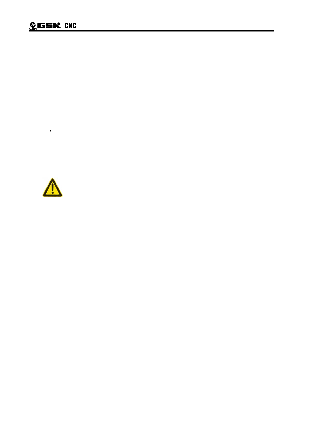
GSK988T Turning CNC System User Manual
Preface
Your Excellency,
We are honored by your purchase of this GSK 988T Turning CNC
System made by GSK CNC Equipment Co., Ltd.
This book is User Manual “Programming and Operation”.
To ensure safe and effective running, please read this manual carefully
before installation and operation.
Warning
Accident may occur by improper connection and operation!This
system can only be operated by authorized and qualified personnel.
Special caution:
The power supply fixed on/in the cabinet is exclusively used for the
CNC system made by GSK.
It can't be applied to other purposes, or else it may cause serious
danger!
II
Page 3

Cautions
■ Delivery and storage
● Packing box over 6 layers in pile is unallowed.
● Never climb the packing box, stand on it or place heavy objects on it.
● Do not move or drag the products by the cables connected to it.
● Forbid collision or scratch to the panel and display screen.
● Avoid dampness, insolation and drenching.
■
Open-package inspection
● Confirm that the products are the required ones.
● Check whether the products are damaged in transit.
● Confirm that the parts in packing box are in accordance with the packing list.
● Contact us in time if any inconsistence, shortage or damage is found.
Contents
■ Connection
● Only qualified personnel can connect the system or check the connection.
● The system must be earthed, and the earth resistance must be less than 0.1Ω.
The earth wire cannot be replaced by zero wire.
● The connection must be correct and firm to avoid any fault or unexpected
consequence.
● Connect with surge diode in the specified direction to avoid damage to the
system.
● Switch off power supply before plugging out or opening electric cabinet.
■ Troubleshooting
● Switch off power supply before troubleshooting or changing components.
● Check the fault when short circuit or overload occurs. Restart can only be done
after troubleshooting.
● Frequent switching on/off of the power is forbidden, and the interval time should
be at least 1 min.
III
Page 4

GSK988T Turning CNC System User Manual
ANNOUNCEMENT!
z This manual describes various possibilities as much as possible. However,
operations allowable or unallowable cannot be explained one by one due to
so many possibilities that may involve with, so the contents that are not
specially stated in this manual shall be regarded as unallowable.
WARNING!
z Please read this manual and a manual from machine tool builder carefully
before installation, programming and operation, and strictly observe the
requirements. Otherwise, products and machine may be damaged,
workpiece be scrapped or the user be injured.
CAUTION!
z Functions, technical indexes (such as precision and speed) described in
this user manual are only for this system. Actual function configuration and
technical performance of a machine tool with this CNC system are
determined by machine tool builder’s design, so functions and technical
indexes are subject to the user manual from machine tool builder.
z Though this system adopts standard operation panel, the functions of the
keys on the panel are defined by PLC program (ladder diagram). It should be
noted that the keys functions described herein are for the standard PLC
program (ladder diagram).
z For functions and effects of keys on control panel, please refer to the user
manual from machine tool builder.
IV
Page 5

Contents
Safety Responsibility
Manufacturer’s Responsibility
——Be responsible for the danger which should be eliminated and/or controlled on
design and configuration of the provided CNC systems and accessories.
——Be responsible for the safety of the provided CNC systems and accessories.
——Be responsible for the provided information and advice for the users.
User’s Responsibility
——Be trained with the safety operation of CNC system and familiar with the safety
operation procedures.
——Be responsible for the dangers caused by adding, changing or altering to the
original CNC systems and the accessories.
——Be responsible for the failure to observe the provisions for operation, adjustment,
maintenance, installation and storage in the manual.
This manual is subject to change without further notice.
This manual is reserved by end user.
We are full of heartfelt gratitude to you for supporting us in the use of GSK’s products.
V
Page 6

GSK988T Turning CNC System User Manual
VI
Page 7

Contents
Contents
Ⅰ PROGRAMMING ..........................................................................................................................1
Chapter I Programming Fundamentals ............................................................................................3
1.1 GSK988T Introduction ........................................................................................................3
1.2 CNC system of machine tools and CNC machine tools......................................................5
1.3 Programming Fundamentals...............................................................................................7
1.3.1 Coordinates definition ...............................................................................................7
1.3.2 Increment system .....................................................................................................9
1.3.3 Max. travel ..............................................................................................................10
1.3.4 Reference position..................................................................................................10
1.3.5 Machine coordinate system ....................................................................................10
1.3.6 Workpice coordinate system................................................................................... 11
1.3.7 Local coordinate system ......................................................................................... 11
1.3.8 Interpolation function ..............................................................................................11
1.4 Coordinate Value and Dimension......................................................................................12
1.4.1 Absolute programming and incremental programming ...........................................12
1.4.2 Diameter programming and radius programming ...................................................13
1.4.3 Decimal programming.............................................................................................14
1.4.4 Conversion between the metric and the inch ..........................................................14
1.4.5 Linear axis and rotary axis ......................................................................................15
1.5 Structure of an NC Program..............................................................................................15
1.5.1 Program name ........................................................................................................16
1.5.2 Block format............................................................................................................16
1.5.3 Word .......................................................................................................................17
1.5.4 Block number..........................................................................................................26
1.5.5 Main program and subprogram...............................................................................26
1.6 Program Run ....................................................................................................................27
1.6.1 Sequence of program run .......................................................................................27
1.6.2 Execution sequence of word...................................................................................28
Chapter II G Commands ................................................................................................................29
2.1 Summary ..........................................................................................................................29
2.1.1 G command classification .......................................................................................29
2.1.2 Omitting word input.................................................................................................31
2.1.3 Related definitions ..................................................................................................33
2.2 Rapid Traverse (Positioning) G00.....................................................................................33
2.3 Linear Interpolation G01 ...................................................................................................34
2.4 Arc Interpolation G02, G03 ...............................................................................................35
2.5 Dwell G04 .........................................................................................................................38
2.6 Cylindrical Interpolation 7.1...............................................................................................39
2.7 Polar Coordinate Interpolation G12.1, G13.1 ....................................................................43
2.8 Metric/Inch Switch G20, G21 ............................................................................................45
2.9 Stored Travel Check G22, G23 .........................................................................................45
2.10 Skip Interpolation G31 ....................................................................................................46
2.11 Automatic Tool Offset G36, G37 ...................................................................................48
2.12 Reference Position Function...........................................................................................50
VII
Page 8

GSK988T Turning CNC System User Manual
2.12.1 Reference position return G28.............................................................................. 50
nd
2.12.2 2
2.13 Related Function of Coordinate System .........................................................................52
2.13.1 Selecting machine coordinate system position G53 .............................................53
2.13.2 Workpiece coordinate system setting G50 ...........................................................54
2.13.3 Workpiece coordinate system selection command G54~G59............................. 55
2.13.4 Local coordinate system setting G52....................................................................57
2.13.5 Level selection command G17~G19 ................................................................... 59
2.13.6 Exact stop mode G61/cutting mode G64.............................................................. 59
2.14 Fixed Cycle Command ...................................................................................................60
2.14.1 Axial cutting cycle G90 .........................................................................................60
2.14.2 Radial cutting cycle G94 .......................................................................................63
2.15 Multiple Cycle Commands .............................................................................................. 66
2.15.1 Axial Roughing Cycle G71.................................................................................... 66
2.15.2 Radial Roughing Cycle G72 ............................................................................... 72
2.15.3 Closed Cutting Cycle G73 ....................................................................................77
2.15.4 Finishing Cycle G70 .............................................................................................82
2.15.5 Axial Grooving Multiple Cycle G74 .......................................................................83
2.15.6 Radial Grooving Multiple Cycle G75 .....................................................................86
2.15.7 Notes for multi cycle machining ............................................................................ 89
2.16 Threading Cutting ........................................................................................................... 90
2.16.1 Thread Cutting with Constant Lead G32............................................................... 90
2.16.2 Thread cutting with variable lead G34 ..................................................................93
2.16.3 Thread cutting cycle G92......................................................................................95
2.16.4 Multiple thread cutting cycle G76..........................................................................97
2.17 Constant Surface Speed Control G96, Constant Rotational Speed Control G97..... 103
2.18 Feedrate per Minute G98, Feedrate per Rev G99 ................................................... 105
2.19 Drilling/Boring Fixed Cycle Command ..........................................................................106
2.19.1 End drilling cycle G83 /side drilling cycle G87 ....................................................107
2.19.2 End Boring CycleG85 / Side Boring Cycle G89 .................................................. 111
2.19.3 Cancelling Drilling/Boring G80............................................................................ 112
2.19.4 Notes for Drilling/Boring Cycle ............................................................................ 112
2.20 Tapping Cycle Command.............................................................................................. 112
2.20.1 Tapping Mode ..................................................................................................... 113
2.20.2 End Rigid Tapping Cycle (G84) / Side Rigid Tapping Cycle (G88)...................... 114
2.20.3 End Common Tapping Cycle (G84) /Side Common Tapping Cycle (G88) .......... 120
2.21 Automatic Chamfering Function.................................................................................... 123
2.22 Macro Command ..........................................................................................................126
2.22.1 Variable...............................................................................................................126
2.22.2 System variable ..................................................................................................127
2.22.3 Operation and jump command ...........................................................................131
2.22.4 Macro program statement and NC statement ..................................................... 136
2.22.5 Macro program call ............................................................................................. 136
, 3rd, 4th reference position return G30 .............................................................51
Chapter Ⅲ MSTF Commands..................................................................................................... 139
3.1 M (Miscellaneous Function) ............................................................................................139
3.1.1 End of program M02 .............................................................................................139
VIII
Page 9

Contents
3.1.2 End of program run M30 .......................................................................................139
3.1.3 Program stop M00 ................................................................................................139
3.1.4 Optional stop M01.................................................................................................140
3.1.5 Subprogram call M98 .........................................................................................140
3.1.6 Subprogram Call M198.........................................................................................141
3.1.7 Return from Subprogram M99............................................................................141
3.1.8 The Following M commands for standard ladder(some functions modified by K
parameters)......................................................................................................................142
3.1.9 M Commands defined by standard PLC ladder ....................................................143
3.2 Spindle Function .............................................................................................................143
3.2.1 Spindle speed analog voltage control ...................................................................143
3.2.2 Spindle override....................................................................................................144
3.3 Tool Function ..................................................................................................................144
3.3.1 Tool offset .............................................................................................................144
3.3.2 Tool Life Management ..........................................................................................147
Chapter IV Tool Nose Radius Compensation...............................................................................151
4.1 Application ......................................................................................................................151
4.1.1 Overview...............................................................................................................151
4.1.2 Imaginary tool nose direction ................................................................................152
4.1.3 Compensation value setting..................................................................................155
4.1.4 G40/G41/G42 command function .........................................................................156
4.1.5 Compensation direction ........................................................................................157
4.1.6 Cautions ...............................................................................................................159
4.1.7 Application ............................................................................................................1
4.2 Tool Nose Radius Compensation Offset Path.................................................................161
4.2.1 Inner and outer side ..............................................................................................161
4.2.2 Tool traversing when starting tool .........................................................................161
4.2.3 Tool traversing in Offset mode ..............................................................................163
4.2.4 Tool traversing in Offset canceling mode ..............................................................168
4.2.5 Tool interference check......................................................................................... 169
4.2.6 Commands for canceling compensation vector temporarily .................................171
4.2.7 Particulars.............................................................................................................174
60
Ⅱ OPERATION ...........................................................................................................................181
Chapter Ⅰ Overview.....................................................................................................................183
1.1 Operation Overview ........................................................................................................183
1.2 System Setting................................................................................................................184
1.3 Display ............................................................................................................................185
1.4 System............................................................................................................................187
1.4.1 System panel........................................................................................................187
1.4.2 System key definitions ..........................................................................................188
1.5 Machine Operation Panel ...............................................................................................190
1.5.1 Division of machine operation panel ..................................................................... 190
1.5.2 State indicator and press key definition on the panel............................................191
Chapter Ⅱ Power on, Power off and Safety Protection ................................................................196
IX
Page 10

GSK988T Turning CNC System User Manual
2.1 Power on ........................................................................................................................196
2.2 Power off.........................................................................................................................197
2.3 Overtravel Protection ......................................................................................................197
2.4 Overtravel Protection in Memory Travel Limit .................................................................197
2.5 Emergence Operation..................................................................................................... 199
2.5.1 Reset ....................................................................................................................199
2.5.2 Emergency stop.................................................................................................... 199
2.5.3 Feed hold..............................................................................................................199
2.5.4 Cutting off power supply ....................................................................................... 199
Chapter Ⅲ Windows ................................................................................................................... 200
3.1 Position Display Window ................................................................................................205
3.1.1 Absolute coordinate window ................................................................................. 206
3.1.2 Relative coordinate display................................................................................... 207
3.1.3 Machine coordinate display ..................................................................................208
3.1.4 Comprehensive coordinate...................................................................................208
3.1.5 Setting the relative coordinate ..............................................................................209
3.1.6 Switching between the mode and the comprehensive message ..........................210
3.1.7 Clearing workpiece count ..................................................................................... 211
3.1.8 Clearing run time .................................................................................................. 211
3.2 Program Window ............................................................................................................ 212
3.2.1 Local directory and U disk directory......................................................................212
3.2.2 MDI program......................................................................................................... 213
3.2.3 Item/times ............................................................................................................. 214
3.3 System Window .............................................................................................................. 214
3.3.1 System parameter setting and rewriting window ..................................................215
3.3.2 Screw pitch compensation setting and rewriting window...................................... 218
3.3.3 System message and operation authority levels ..................................................219
3.3.4 System file management ......................................................................................222
3.3.5 Ladder diagram ....................................................................................................223
3.4 Setting Window............................................................................................................... 229
3.4.1 Tool offset setting.................................................................................................. 229
3.4.2 CNC setting window .............................................................................................233
3.4.3 Macro variable window .........................................................................................238
3.5 Message Window ...........................................................................................................239
3.5.1 Alarm message check window .............................................................................240
3.5.2 Alarm record check window.................................................................................. 241
3.5.3 Diagnosis window................................................................................................. 242
3.5.4 Oscillograph window............................................................................................. 245
3.5.5 GSK-CAN window ................................................................................................248
3.6 Graph Window ................................................................................................................ 249
3.6.1 Setting graph parameter .......................................................................................249
3.6.2 Processing graph path.......................................................................................... 250
3.6.3 Simulation graph................................................................................................... 251
3.7 Help Windows................................................................................................................. 252
Chapter Ⅳ Editing and Managing a Program .............................................................................254
X
Page 11

Contents
4.1 Searching, Creating, Executing and Opening a Program ...............................................254
4.1.1 Searching a program ............................................................................................254
4.1.2 Creating a program ...............................................................................................254
4.1.3 Executing a program.............................................................................................255
4.1.4 Opening a program...............................................................................................256
4.2 Renaming, Outputting, Deleting and Arraying Programs, Saving a Program as.............257
4.2.1 Renaming a program ............................................................................................257
4.2.2 Saving a program as.............................................................................................258
4.2.3 Deleting a program ...............................................................................................259
4.2.4 Outputting a program............................................................................................259
4.2.5 Arraying programs ................................................................................................260
4.3 Editing and Rewriting a Program ....................................................................................260
4.3.1 Editing a program .................................................................................................260
4.3.2 Rewriting a program .............................................................................................261
4.3.3 Shortcut key..........................................................................................................262
4.4 Block Comment...............................................................................................................263
4.5 Generating a Block Number............................................................................................263
4.6 Background Editing a Program .......................................................................................263
Chapter Ⅴ Manual Operation .....................................................................................................264
5.1 Manual Reference Position Return .................................................................................264
5.2 Manual Feed...................................................................................................................265
5.3 Increment Feeding ..........................................................................................................266
5.4 MPG Feeding...............................................................................................................
...267
Chapter Ⅵ Auto Operation............................................................................................................270
6.1 Auto Running ..................................................................................................................270
6.1.1 Selecting the running program..............................................................................270
6.1.2 Program running ...................................................................................................271
6.1.3 Running from any block ........................................................................................272
6.1.4 Skip.......................................................................................................................272
6.1.5 G31 skip ...............................................................................................................273
6.1.6 Stop auto running..................................................................................................273
6.2 MDI Running ...................................................................................................................274
6.2.1 Editing and running the program in MDI mode .....................................................274
6.2.2 Running from any block ........................................................................................275
6.2.3 Stop MDI running .................................................................................................. 275
6.3 DNC Running..................................................................................................................275
6.4 Auto Running Control......................................................................................................278
6.4.1 Machine and miscellaneous function lock.............................................................278
6.4.2 Dry run..................................................................................................................279
6.4.3 Single block running .............................................................................................280
6.4.4 Feedrate override .................................................................................................280
6.4.5 Rapid traverse override ........................................................................................281
Chapter Ⅶ Tool Offset and Setting Tools ....................................................................................282
7.1 Setting the Tool Offset and the Wearing Values..............................................................282
XI
Page 12

GSK988T Turning CNC System User Manual
7.1.1 Direct input method ..............................................................................................282
7.1.2 Measuring mode................................................................................................... 283
7.1.3 +input mode.......................................................................................................... 284
7.1.4 C input method .....................................................................................................285
7.1.5 Clearing the offset value or the wearing value ......................................................286
7.2 Fixed-Point Tool Setting ..................................................................................................287
7.3 Trial Cut Toolsetting ........................................................................................................287
7.4 Position Record ..............................................................................................................290
7.5 Automatic Tool Compensation ........................................................................................290
Chapter Ⅷ Setting and Display Graphs ...................................................................................... 292
8.1 Setting the Graph Parameter .......................................................................................... 292
8.2 Path Graph Display and Operation ................................................................................. 293
8.3 Simulation graph display and operation ..........................................................................294
Chapter Ⅸ U disk Use ................................................................................................................ 296
9.1 Sending a Program......................................................................................................... 296
9.2 Backup Value..................................................................................................................297
9.2.1 System file backup ...............................................................................................297
9.2.2 Servo parameter backup ......................................................................................298
Chapter Ⅹ Processing Examples ................................................................................................. 301
10.1 Outer End Face Machining ...........................................................................................301
10.2 Compound Machining................................................................................................... 304
Chapter Ⅺ Parameters ............................................................................................................... 310
11.1 Parameters Related to System Setting ......................................................................... 311
11.2 Parameters Related to Interfaces of Input and Output .................................................. 311
11.3 Parameters Related to Axis Control/Setting Unit........................................................... 311
11.4 Parameters Related to Coordinate System................................................................... 315
11.5 Parameters Related to the Stroke Detection................................................................. 317
11.6 Parameters Related to Feedrate ................................................................................... 320
11.7 Parameters Related to Control of Acceleration and Deceleration ................................. 324
11.8 Parameters Related to Servo and Backlash Compensation .........................................326
11.9 Parameters Related to Input/Output .............................................................................330
11.10 Parameters Related to Display and Editing................................................................. 332
11.11 Parameters Related to Programming .......................................................................... 334
11.12 Parameters Related to Screw Pitch Error Compensation ...........................................336
11.13 Parameters Related to the Spindle Control................................................................. 339
11.14 Parameters Related to the Tool Compensation........................................................... 344
11.15 Parameters Related to the Canned Cycle................................................................. 347
11.15.1 Parameter of the Drilling Canned Cycle ............................................................347
11.15.2 Parameters Related to the Thread Cutting Cycle.............................................. 348
11.15.3 Parameters Related to the Combined Canned Cycle .......................................348
11.16 Parameters Related to the Rigid Tapping.................................................................... 349
11.17 Parameters Related to the Polar Coordinate Interpolation.......................................... 351
11.18 Parameters Related to the User Macro Program ........................................................ 352
XII
Page 13

Contents
11.19 Parameters Related to Skip Function..........................................................................353
11.20 Parameters Related to Graphic Display ......................................................................355
11.21 Parameters Related to Run Hour and Parts Count Display.........................................355
11.22 Parameters Related to MPG Feed ..............................................................................356
11.23 Parameters Related to PLC Axis Control ....................................................................357
11.24 Parameters Related to Basic Function........................................................................360
11.25 Parameters Related to GSK-CAN Communication Function ......................................361
Appendix 1 Alarm List ..................................................................................................................363
1.1 Program Alarms (P/S Alarms) .........................................................................................363
1.2 Parameter Alarms ...........................................................................................................372
1.3 Pulse Encoder Alarms.....................................................................................................373
1.4 Servo Alarms ..................................................................................................................373
1.5 Overtravel Alarms ...........................................................................................................373
1.6 Spindle Alarms................................................................................................................374
1.7 System Alarms................................................................................................................374
1.8 Communication prompt on the operation panel ..............................................................375
1.9 GSK-CAN Communication Prompts ...............................................................................375
1.10 Servo Inner Alarms .......................................................................................................377
Appendix 2 Standard Ladder Function Allocation.........................................................................381
2.1 X, Y Addresses Definition................................................................................................381
2.2 Standard Operation Panel...............................................................................................384
2.2.1 Address X .............................................................................................................384
2.2.2 Address Y .............................................................................................................386
2.3 Standard PLC Parameter Instruction ..............................................................................389
2.3.1 Parameter K..........................................................................................................389
2.3.2 Parameter DT .......................................................................................................390
2.3.3 Parameter DC.......................................................................................................391
2.3.4 Parameter D .........................................................................................................391
2.4 PLC(Address A) Alarms (the Followings are Referred to V2.03b)...................................392
Appendix 3 Installation .................................................................................................................394
3.1 GSK988T Appearance Dimension ..................................................................................394
3.2 Machine Operation Panel MPU02A of GSK988T............................................................395
3.3 Machine Operation Panel MPU02B Appearance dimension of GSK988T ......................396
3.4 GSK988T-H Appearance Dimension...............................................................................397
3.5 Appearance Dimension of GSK988T-H Operation panel................................................397
Appendix 4 Operation List............................................................................................................399
XIII
Page 14

GSK988T Turning CNC System User Manual
XIV
Page 15

Chapter 1 Programming Fundamentals
Ⅰ Programming
Ⅰ PROGRAMMING
1
Page 16

GSK988T Turning CNC System User Manual
Ⅰ Programming
2
Page 17
Chapter Ⅰ Programming Fundamentals
Chapter I Programming Fundamentals
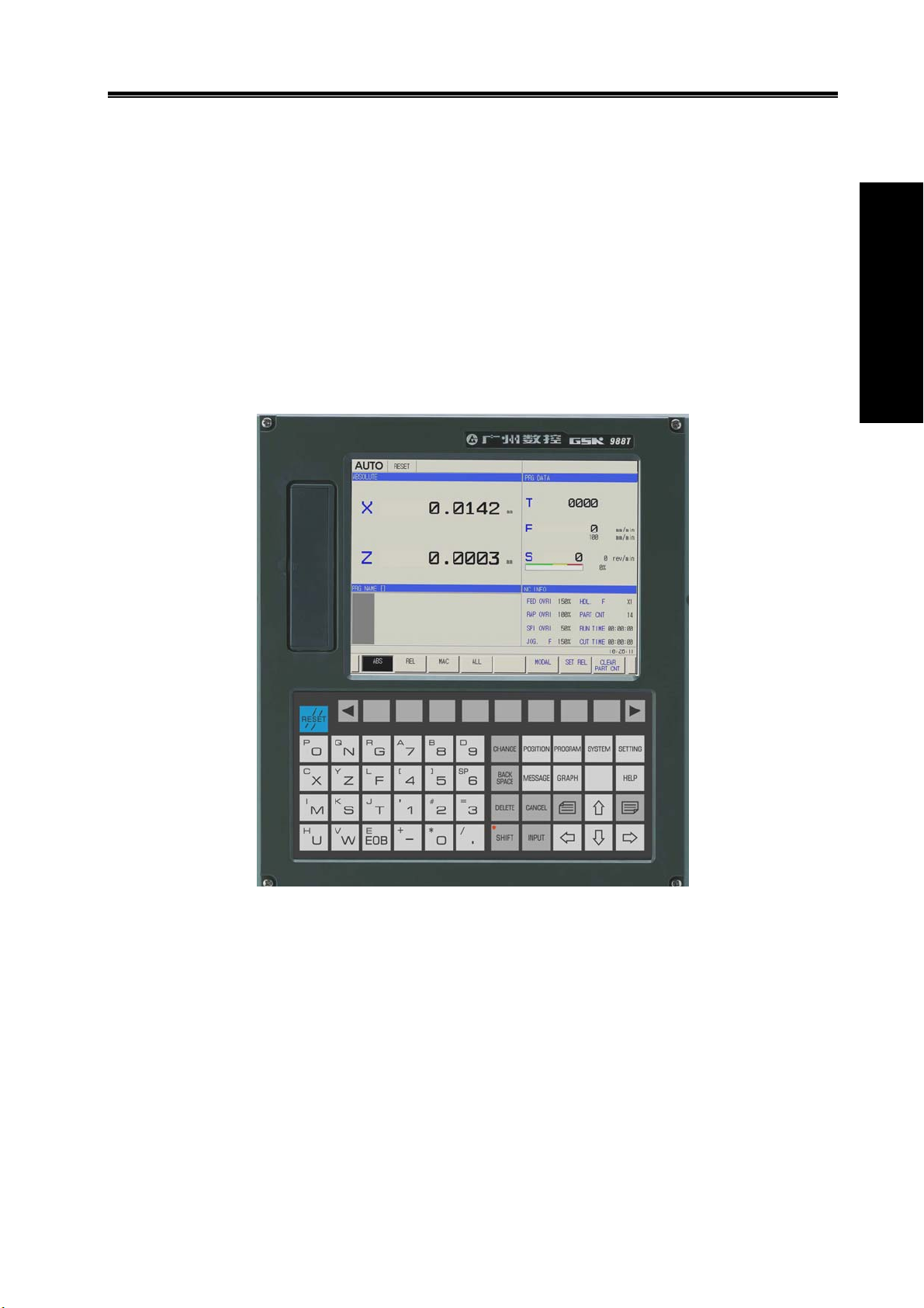
1.1 GSK988T Introduction
GSK988T is exclusive to the slant bed CNC turning machine and turning center with the
horizontal and the vertical structures. It uses 400MHz high-performance process to control 5 feed
axes(including Cs axis) and 2 spindles, communicates with the servo unit through GSK-CAN serial
bus, and its matched servo motor uses the high-resolution absolute encoder to realize 0.1μm
position precision, which can meet the requirements of high-precision turning and milling compound
machining. It has the network interface to support the remote monitor and file transmission and to
meet the network teaching and workshop management. GSK988T is the best choice for the slant bed
CNC turning and turning center.
Programming Ⅰ
Fig. 1-1 GSK988T appearance
Technical characteristics
5 feed axes(including Cs axis), 3-axis link, 2 analog spindles to realize the turning, milling compound
machining
Command unit 1μm and 0.1μm, max. speed 60m/min(max. speed 24m/min in 0.1μm)
Optional to GSK-CAN servo unit to read/write the servo parameter and monitor servo unit
Extended I/O unit and GSK-CAN axis through serial bus
Nested many PLC programs, on-line editing, real-time monitoring PLC ladder
Part programs edited on the background
Network interface, remote monitoring and file transmission
USB interface, U disc file operation, system allocation and software upgrading
8.4 inch truecolor LCD, two-dimensional motion path and solid graph display
3
Page 18

GSK988T Turning CNC System User Manual
Technical specifications
Controllable axes
Max. controllable axes:5(including Cs axis)
Max. link axes:3
PLC controllable axes:5
Ⅰ Programming
Feed axis function
Least command unit:0.001mm, 0.0001mm
Least command range:±99999999× least command unit
Rapid traverse speed:max. 60m/min in 0.001mm command unit, max. 24m/min in 0.0001mm
command unit
Rapid override:F0, 25%, 50%, 100% real-timing tuning
Cutting feedrate:
0.01 mm/min~60000 mm/min or 0.01 inch/min~4000 inch/min(G98: feed per minute)
0.01 mm/rev~500 mm/r or 0.01 inch/rev~9.99 inch/rev(G99: feed per revolution)
Feedrate override:0~150% 16-level real-time tuning
Interpolation mode: linear, arc, thread, polar interpolation, and rigid tapping
Thread function
Thread type: constant pitch straight thread/taper thread/end thread, variable pitch straight
thread/taper thread/end thread
Thread head:1~99 heads
Thread pitch: 0.01mm~500mm(metric thread)or 0.01inch~9.99inch(inch thread)
Thread run-out:thread lenght, angle, speed can be set
Acceleration/deceleration function
Cutting feed: linear, exponential
Rapid traverse: linear
Thread cutting: linear, exponential
Initial speed, terminal speed and time of acceleration/deceleration are set by the parameter
Spindle function
2-channel 0V~10V analog voltage output,2-channel spindle encode feedback, double-spindle
control
Spindle speed: spindle speed specified by S or PLC signal, its range: 0rpm~20000rpm
Spindle override:50%~120% 8-level real-time tuning
Spindle constant surface control
Rigid tapping
Tool function
Tool length compensation(tool offset):99 groups
Tool wear compensation:99 groups of tool wear compensation data
Tool nose radius compensation(C type)
Toolsetting mode: fixed-point toolsetting, trial-cutting toolsetting, reference position return toolsetting
Offset execution mode: modifying coordinate mode, tool traverse mode
Precision compensation
Backlash compensation: compensation range (-9999~9999)× check unit
Memory pitch error compensation:1024 compensation points,compensation point number of each is
set by the parameter, each point compensation range (-700~700) × check unit
PLC function
13 basic commands, 30 functional commands
4
Page 19

Chapter Ⅰ Programming Fundamentals
PLC ladder on-line edit, real-time monitoring
st
2-level PLC program, up to 5000 steps, the 1
Many PLC programs(up to 16 programs),the current running PLC program can be selected
level program refresh period
I/O unit
Basic I/O:40 input /32 output
Operation panel I/O:96 input/96 output
Human-computer interface
Display in Chinese, English and others
Two-dimensional tool path and solid graph display
Servo state monitoring
Servo parameter on-line allocation
Real-time clock
On-line help
Operation management
Operation mode: Auto, Manual, Edit, MDI, DNC, MPG, Reference position return
Multi-level operation Authorization Management
Alarm log
Timed stop
Program edit
Program capacity:36M, 10000 programs(including subprogram and macro program)
Edit mode: full-screen edit, part program edit on the background
Edit function:searching, modifying and deleting program/block/word, copying/deleting block
Program format: ISO code, word without blank space, relative coordinates, absolute coordinate
compound programming
Macro command: statement macro command program
Program call: macro program call with parameters, 12-level subprogram nesting
Grammar check: executing the rapid grammar check for the program(do not run the program) after it
has been edit
Communication function
RS232 interface: part program and parameter transmission, DNC machining, upgrading PLC
program and system software U disc
USB:U disc file operation, U disc file directly machining, upgrading PLC program and system
software U disc
LAN: remote monitoring, network DNC machining, file transmission, remotely upgrading PLC
program, system software
Safety function
Emergency stop
Hardware travel limit
Many storage travel checks
Data backup and recover
Programming Ⅰ
1.2 CNC system of machine tools and CNC machine tools
CNC machine tool is an electro-mechanical integrated product, composed of Numerical Control
Systems of Machine Tools, machines, electric control components, hydraulic components, pneumatic
components, lubricating, cooling and other subsystems (components), and CNC systems of machine
tools are control cores of CNC machine tools. CNC systems of machine tools are made up of
computerized numerical control(CNC), servo (stepper) motor drive devices, servo (or stepper) motor
5
Page 20

GSK988T Turning CNC System User Manual
etc.
Operational principles of CNC machine tools: according to requirements of machining technology,
edit user programs and input them to CNC, then CNC outputs motion control commands to the servo
(stepper) motor drive devices, and last the servo (or stepper) motor completes the cutting feed of
machine tool by mechanical driving device; logic control commands in user programs to control
Ⅰ Programming
spindle start/stop, tool selections, cooling ON/OFF, lubricant ON/OFF are output to electric control
systems of machine tools from CNC, and then the electric control systems control output components
including buttons, switches, indicators, relays, contactors and so on. Presently, the electric control
systems are employed with Programmable Logic Controller (PLC) with characteristics of compact,
convenience and high reliance. Thereof, the motion control systems and logic control systems are the
main of CNC machine tools.
The system has simultaneously motion control and logic control function to control two axes of CNC
machine tool to move, and has PLC function. Edit PLC programs (ladder diagram) according to
requirements of input and output control of machine tool and then download them to GSK988T
Turning Machine CNC system, which realizes the required electric control requirements of machine
tool, is convenient to electric design of machine tool and reduces cost of CNC machine tool.
Softwares used for controlling GSK988T Turning Machine CNC system are divided into system
software (NC for short) and PLC software (PLC for short). NC system is used for controlling display,
communication, edit, decoding, interpolation and acceleration/deceleration, and PLC system for
controlling explanations, executions, inputs and outputs of ladder diagrams.
Standard PLC programs are loaded (except for the special order) when GSK980TDa Turning
Machine CNC System is delivered, concerned PLC control functions in following functions and
operations are described according to control logics of standard PLC programs, marking with
“Standard PLC functions” in GSK980TDa Turning CNC System User Manual. Refer to Operation
Manual of machine manufacturer about functions and operations of PLC control because the
machine manufacturer may modify or edit PLC programs again.
Programming is a course of workpiece contours, machining technologies, technology parameters and
tool parameters being edit into part programs according to special CNC programming G codes. CNC
machining is a course of CNC controlling a machine tool to complete machining of workpiece
according requirements of part programs. Technical flow of CNC machining is shown in Fig. 1-2.
6
Page 21

Chapter Ⅰ Programming Fundamentals
Analyse workpiece drawings and confirm
machining processing
Edit part programs and record into CNC
Test part programs and execute trial run
O0001;
G00 X3.76 Z0;
G01 Z-1.28 F50;
…
M30;
%
Programming Ⅰ
Execute toolsetting and set tool offsets and
coordinates
Run part programs and machine workpiece
Check part dimension and modify part
programs and compensations
The machining ends and the workpiece is
formed
Fig. 1-2
1.3 Programming Fundamentals
1.3.1 Coordinates definition
The following figure is the sketch of CNC turning:
7
Page 22
GSK988T Turning CNC System User Manual
Ⅰ Programming
Fig. 1-3
GSK988T uses a rectangular coordinate system composed of X, Z axis. X axis is perpendicular
with axes of spindle and Z axis is parallel with axes of spindle; negative directions of them approach
to the workpiece and positive ones are away from it.
Parameter NO.1020 can set and modify program names for each axis and their responding
relationship is as follows:
Table 1-3(a)
Axis name Setting value Axis name Setting value
X 88 Z 90
Y 89 A 65
B 66 C 67
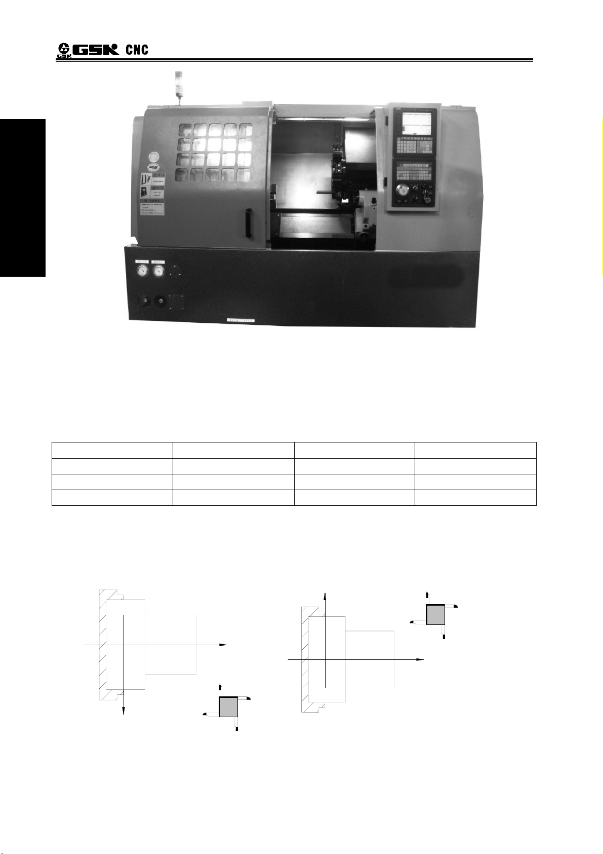
There is a front tool post and a rear tool post of NC turning machine according to their relative
position between the tool post and the spindle, Fig. 1-5 is a coordinate system of the front tool post
and Fig. 1-6 is a rear toolpost one. It shows exactly the opposite of X axes, but the same of Z axes
from figures. In the manual, it will introduce programming application with the front tool post
coordinate system in the following figures and examples.
Fig.1-4 Front tool post coordinate system Fig.1-5 Rear tool post coordinate system
8
X
Z
Z
X
Page 23

Chapter Ⅰ Programming Fundamentals
1.3.2 Increment system
Increment system includes least input increment (input) and least command increment (output).
Least input increment is the least unit of programming movement distance. Least command
increment is the least unit of tool movement on the machine tool. Their unit: mm, inch or degree.
Increment systems are separately IS-B and IS-C. Bit 1 of NO. 1004 decides to select IS-B or IS-C. Bit
1 (ISC) setting of No.1001 is applied to all axes. For example: increment system of all axes is set to
IS-C when the parameter selects IS-C.
Table 1-3(b) increment system IS-B
Least input increment Least command increment
Metric machine
Inch machine
Least input increment Least command increment
Metric machine
Inch machine
Whether the least input increment is mm or inch is determined by the machine based on the
parameter INM(1001#0). The least input increment can be switched between the inch and the mm
input, which is controlled by G codes( G20 or G21) or the set parameter.
mm input
Inch input
mm input
Inch input
mm input
Inch input
mm input
Inch input
0.001mm(diameter)
0.001mm(radius)
0.001deg
0.0001inch(diameter)
0.0001inch(radius)
0.001deg
0.001mm(diameter)
0.001mm(radius)
0.001deg
0.0001inch(diameter)
0.0001inch(radius)
0.001deg
Table 1-3(c) increment system IS-C
0.0001mm(diameter)
0.0001mm(radius)
0.0001deg
0.00001inch(diameter)
0.00001inch(radius)
0.0001deg
0.0001mm(diameter)
0.0001mm(radius)
0.0001deg
0.00001inch(diameter)
0.00001inch(radius)
0.0001deg
0.0005mm
0.001mm
0.001deg
0.0005inch
0.001inch
0.001deg
0.00005mm
0.0001mm
0.001deg
0.00005inch
0.0001inch
0.001deg
0.00005mm
0.0001mm
0.0001deg
0.00005inch
0.0001inch
0.0001deg
0.000005mm
0.00001mm
0.0001deg
0.000005inch
0.00001inch
0.0001deg
Programming Ⅰ
9
Page 24
GSK988T Turning CNC System User Manual
1.3.3 Max. travel
Max. travel=least command increment X(±)99999999
Table 1-3 (d) max. travel IS-C
Ⅰ Programming
IS-B
IS-C
Note 1: The unit is diameter value in diameter programming, is radius value in radius programming in the
above table.
Note 2: The input command cannot exceed max. travel command.
Note 3: The actual travel decides the machine tool.
Increment system Max. travel
Metric machine system ±99999.999mm
±99999.999deg
Inch machine system ±9999.9999inch
±9999.9999deg
Metric machine system ±9999.9999mm
±9999.9999deg
Inch machine system ±999.99999inch
±9999.9999deg
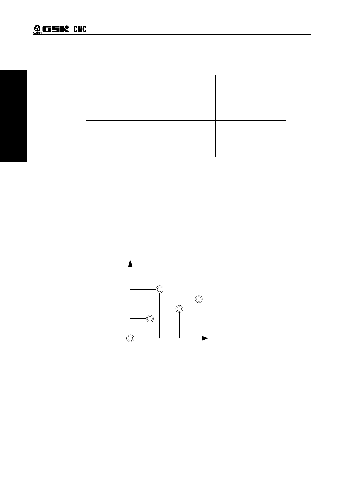
1.3.4 Reference position
Reference position is a fixed point on the machine tool. The tool can move to the position by
executing the reference position return function. Generally, the reference position is used to tool
change and setting coordinate system. GSK988T Turning CNC System can set 4 reference positions
by parameters as follows:
Y
nd
reference point
2
rd
3
reference point
reference point
Machine zero
th
reference point
4
X
Fig. 1-6 reference position
1.3.5 Machine coordinate system
Machine tool coordinate system is a benchmark one used for CNC counting coordinates and a
fixed one on the machine tool. Machine tool zero is a fixed point which position is specified by zero
switch or zero return switch on the machine tool. Usually, the zero return switch is installed on max.
stroke in axis positive direction. After the system is turned on, the reference position return is
executed to set machine coordinate system. The machine coordinate system is not keeping until the
system is turned off.
Note: For the machine with the incremental encoder, must execute the reference position return every time to
set the machine coordinate system after power-off; for the machine with the multi-coil absolute encoder,
need not execute the reference position return every time after power-off.
10
Page 25

Chapter Ⅰ Programming Fundamentals
1.3.6 Workpice coordinate system
The workpiece coordinate system is a rectangular coordinate system based on the part drawing,
also called floating coordinate system. The workpiece coordinate system is set by the system in
advance, can be changed by moving its coordinate origin point. The established workpiece is valid till
it is replaced by a new one. The system has preset 6 workpice coordinate systems (G54-G59).
1.3.7 Local coordinate system
When the system compiling programs in the workpiece coordinate system, sub-coordinate
system of workpiece coordinate system can be set for easily programming, called local coordinate
system as follows:
Local coordinate system
Workpiece coordinate system
Programming Ⅰ
Machine coordinate system
Fig. 1-7 local coordinate system
1.3.8 Interpolation function
Interpolation is defined as a planar or three dimensional contour formed by path of 2 or multiple
axes moving at the same time, also called Contour control. The controlled moving axis is called link
axis when the interpolation is executed. The moving distance, direction and speed of it are controlled
synchronously in the course of running to form the required Composite motion path. Positioning
control is defined that motion end point of one axis or multiple axes instead of the motion path in the
course of running is controlled.
GSK988T has linear, arc and thread interpolation function.
Linear interpolation: Composite motion path of X, Z axis is a straight line from starting point to
end point.
Circular interpolation: Composite motion path of X, Z axis is arc radius defined by R or the circle
center (I, K) from starting point to end point.
Thread interpolation: Moving distance of X or Z axis or X and Z axis is defined by rotation angle
of spindle to form spiral cutting path on the workpiece surface to realize the
thread cutting. For thread interpolation, the feed axis rotates along with the
spindle, the long axis moves one pitch when the spindle rotates one rev,
and the short axis and the long axis directly interpolate.
Note 1:Xp, Yp, Zp are separately X or its parallel axis, Y or its parallel axis, Z or its parallel axis. The followings
are the same as those.
Note 2: IP expresses the combination of X_Y_Z_(used in programming).
11
Page 26
GSK988T Turning CNC System User Manual
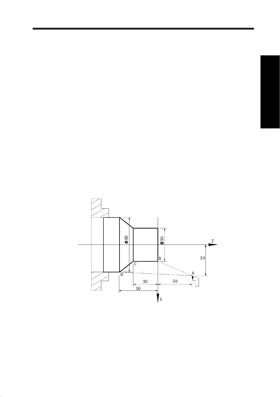
Example:
Ⅰ Programming
Fig.1-8
…
G32 W-27 F3; (B→C;thread interpolation)
G1 X50 Z-30 F100;
G1 X80 Z-50; (D→E;linear interpolation)
G3 X100 W-10 R10; (E→F;arc interpolation)
…
M30;
1.4 Coordinate Value and Dimension
1.4.1 Absolute programming and incremental programming
The system has two methods to command the too traverse: absolute value and incremental
value command. In the absolute programming, use the coordinate value programming of the end
point; in the incremental programming, use the traverse distance programming. In the system, using
the absolute programming or incremental programming is depended on the word of the command as
follows:
Table 1- 4(a)
Absolute value command Incremental value command
X movement command X U
Y movement command Y V
Z movement command Z W
C movement command C H
A movement command A None
B movement command B None
The system can select the incremental programming or the absolute programming mode, or the
incremental/absolute compound programming; the absolute command and the incremental command
can be in the same block as follow:
X100.0 W100.0;
When the absolute command and the incremental command of one axis are in the same block,
the following command value is valid.
12
Page 27
Chapter Ⅰ Programming Fundamentals
The axis word can exist repetitively in the same block and the later value is valid, but when
No.3403 Bit 6 (AD2) is set 1, the alarm occurs. U, W in other G command has bee specified to others.
For example: in G73, the above conditions
1.4.2 Diameter programming and radius programming
Because the workpiece section is the circle in CNC turning controlled program, X dimension can
use two kind of method; diameter programming command and radius programming command.
1. The user can select the radius programming or diameter programming, which is set by state
parameter (No. 1006 Bit 3(DIAX)).
2. Parameters related to diameter/radius programming:
State parameter No.1006 BIT3 (DIAx):
0—radius programming;
1—diameter programming;
State parameter No.5004 Bit1(ORC):
0—offset value is expressed with diameter;
1—offset value is expressed with radius;
Pay more attention to the conditions in the following table when X uses diameter programming:
Table 1- 4 (b) related addresses and data to the diameter or radius programming
Word Explanation Diameter
programming
X
X coordinate, polar
coordinate
G50 sets X coordinate Diameter
Diameter
value
value
X increment Diameter
value
G71 infeed amount Radius value
U
X finishing allowance in
Parameter definition
G71, G72, G73
Related
addresses to
diameter/radius
programming
R
tool retraction
amount in G73
Clearance in G71, G72 Radius value
Clearance after cutting in
G75
Clearance to end point in
G74
Taper in G90, G92, G94,
Radius value
Diameter
value
Diameter
value
Radius value
G76, radius in G02, G03,
thread finishing amount in
G76
I X amount of circle center Radius value
F
G32,G34,G92,Pitch long
axis is X in G76
Radius value
X feedrate display Radius/rev, radius /min
Others X or U value of
position
Display Diameter
value
window
Radius
programming
Radius value
Radius value
Radius value
Radius value
Radius value
Radius value
Programming Ⅰ
Note: Besides the above-mentioned addresses and data related to the diameter programming or the radius
programming, other related to word and data related to X numerical value are expressed with radius
value.
13
Page 28

GSK988T Turning CNC System User Manual
1.4.3 Decimal programming
Value can be input by decimal programming. Distance, time and speed can be input by decimal
programming. The following addresses can use decimal point: X, Y, Z, A, B, C, U, V, W, H, I, J, K, R
and F, and other addresses cannot use decimal programming.
Ⅰ Programming
There are two types of decimal point usage which is decided by No. 3401 Bit0(DPI).
When NO.3401 Bit 0(DPI) is set to 1, value without decimal point is with mm, inch.
When NO.3401 Bit0(DPI) is set to 0, input value is specified by least input increment.
Parameter setting Least command unit
Rotary axis is
Rotary axis
ROTx=1
Linear axis
Example: when the metric input, the least input increment unit are set to 0.001:
Program command The corresponding actual
X1000 without decimal
command value
X1000.0 with decimal
command value
The decimal which is less than the least input increment unit is discarded in course of program
being executed.
Example: X2.34567. When the least unit of input increment is 0.001mm, X2.34567 becomes
X2.345, when the least unit is 0.0001inch, it becomes X2.3456.
The system alarms when the specified is more than 8-digit value.
not related to
parameter INI
Metric
INI=1
Inch
value when DPI is 1
1000mm
Unit:mm
1000mm
unit:mm
ISC=0(ISC system)
ISC=1
(ISB system)
ISC=0(ISC system)
ISC=1(ISB system)
ISC=0(ISC system)
ISC=1(ISB system)
The corresponding actual value when
DPI is 0
1 mm
Unit: least input increment( set to 0.001)
1000mm
Unit:mm
0.001deg ROTx=0
0.0001deg
0.001mm INI=0
0.0001mm
0.0001inch
0.00001inch
1.4.4 Conversion between the metric and the inch
Metric input or inch input is set by NO.0000 Bit2(INI). G commands corresponding to metric/inch
system is as follows:
G20: inch input ;
G21: mm input.
Input data unit becomes the inch or metric input unit when NO.0000 Bit2 (INI) setting is changed.
But, the angle unit is not changed.
Input data unit becomes the inch or metric input unit when NO.0000 Bit2 (INI) setting is changed.
But, the angle unit is not changed.
——F feedrate;
——position command;
——zero offset of workpiece;
——tool compensation value;
14
Page 29
Chapter Ⅰ Programming Fundamentals
——graduation unit of MPG;
——movement distance in incremental feed.
NO.1001 Bit0 (INM) can set MM or INCH input of least command increment in linear axis.
0:mm input( metric machine)
1:inch input(inch machine)
1.4.5 Linear axis and rotary axis
NO.1006 Bit0(ROTx) can set each axis to linear axis or rotary axis. NO. 1006 Bit 1 (ROSx) can
be used to select the rotary type for each axis.
Absolute coordinate value is displayed circularly with the movement per rev set by NO.1260
when the cycle function is executed, which can prevent the rotary axis from overflowing. The cycle
function is valid when NO.1008 Bit 0(ROAx) is set to 1.
For absolute value command, the coordinate values is the corresponding angle cycle value of
per rev set by NO. 1260 after the machine moves. When NO.1008 Bit 1(RABx) is set to 0, the
machine rotates according to the shortest distance(to the target point). For incremental command, the
machine moves according to the angle defined by the command.
Programming Ⅰ
1.5 Structure of an NC Program
User needs to compile part programs (called program) according to command formats of CNC
system. CNC system executes programs to control the machine tool movement, the spindle
starting/stopping, the cooling and the lubricant ON/OFF to complete the machine of workpiece.
Program example:
Fig. 1-9
O0001 ; (Program name)
N0005 G0 X100 Z50; (Rapidly positioning to A point)
N0010 M12; (Clamping workpiece)
N0015 T0101; (Changing No.1 tool and executing its offset)
N0020 M3 S600; (Starting the spindle with 600 r/min)
N0025 M8 (Cooling ON)
N0030 G1 X50 Z0 F600; (Approaching B point with 600mm/min)
15
Page 30

GSK988T Turning CNC System User Manual
N0040 W-30 F200; (Cutting from B point to C point)
N0050 X80 W-20 F150; (Cutting from C point to D point)
N0060 G0 X100 Z50; (Rapidly retracting to A point)
N0070 T0100; (Canceling the tool offset)
Ⅰ Programming
The tool leaves the path of A→B→C→D→A after the above-mentioned programs are executed.
ending with “%”; a block begins with block number (omitted) and ends with “;” or “*”. See the general
structure of program as Fig. 1-10:
Program name
N0080 M5 S0; (Stopping the spindle)
N0090 M9; (Cooling OFF)
N0100 M13; (Releasing workpiece)
N0110 M30; (End of program, spindle stopping and Cooling OFF)
A program consists of a sequence of blocks, beginning with “OXXXX”(program name)and
Program annotation
Block skip character
Block number
Character for end of block
Character for end of block
Fig. 1-10 Structure of a program
Word
Block
Program
1.5.1 Program name
Format: ○ △△△△
Program number (0000~9999, the leading zero can be omitted)
Address O
is number of a program name, its range is 4△△△△ -digit integer 0000~9999, the system
alarms when the negative program name is input. The system ignores NC commands when program
are edited and other NC commands are edited in the first line.
1.5.2 Block format
1. Format: / N countless words; △△△△
/: skip character. A block can have or not it, generally, it is placed in the initial
position of a program; user can press “SKIP” on the operation panel to
execute the operation when the skip function is valid, otherwise, the
“SKIP” key on the operation panel is valid, i.e. the skip character in the
block is invalid;
N△△△△△:block number. A block can have or not it; number following N is △△△△△
5-digit positive integer 00001~99999, and the system alarms when the
input number is decimal.
16
Page 31

Chapter Ⅰ Programming Fundamentals
Countless words: one block can input countless words, and one block can have one or
more words or have no words.
,:
“EOB” is a end character when one block is completed, “;” is displayed in
LCD, there must be have one end character for one block;
2. Format requirements
(1)
In one block, there can be no blank space between block number and word, and can
be countless blank space(the total characters of one block is within 255);
(2)In one block, there can be not or be countless space between skip character and block
number or words;
(3)
In one block, there can be not or be countless space between end character of block
and its front word or blocks;
Each block can be up to 255 characters, including skip character, block number,
command, space, end character of block “;”;
(4)
The system automatically ignores the content with small bracket “(”,“)”.
Explanations of program annotation:
Note: The annotation of program home as the total annotation of a program is displayed in the program
catalog window, the created program automatically creates the small brackets “(”、“)”, if they are
deleted, the system has no them and they can be replaced by “;”.
3.Parameters related block number:
(1)
whether the system automatically creates block number or not:
User can set whether the system automatically creates block number or not in
editing program by setting Bit 5(SEQ) of NO.0000;
(2)
Note: Sprit(/) explanations:
1. When the sprit (/) is used to skip character, it is generally placed the beginning of block, otherwise , and the
messages from the sprit to EOB code are ignored. For example: U10.G00/04; when the skip function is
started, the system executes U10. G00;(G00 U10.), when it stops, the system executes U10. G0004;(G04
U10.);
2. For cycle command buffer, when a block reads from memory to buffer memory, whether the skip function is
valid or not has been executed. After a block reads into buffer memory, i.e. the system changes skip switch
state, but does not influence the block which has read into the buffer memory;
3. Sprit (/) (closed in bracket[]) and sprit(/) right to value statement “=” in <Expression> are taken as division
operation character instead of skip character.
Use can set the interval value in automatically creating block number by setting
NO.3216.
Programming Ⅰ
1.5.3 Word
1. Format: address + number. There must not be space between address and number.
Presently, the system permissively input addresses: G, M, S, T, F, X, Y, Z, U, V, W, P, Q, I, J, K, R,
L, A, B, C, H , N, O, and will add other;
Command number range following address is referred to the following table.
Table 1-5-1 word table
Address
O
N
G
Function mm input inch input Related G
Program name
Line label
Preparatory function See G code See G code
0~9999 0~9999
1~99999 1~99999
codes
17
Page 32

GSK988T Turning CNC System User Manual
M
S
Miscellaneous function
Spindle speed
Ⅰ Programming
T
F
X
Y
Z
A
B
C
U
Tool offset
Feedrate per minute
Feedrate per rev
Pitch
X absolute coordinate
value((linear axis),
delay time
(*1)
Y absolute coordinate
value(linear axis)
(*1)
Z absolute coordinate
value (linear axis)
(*1)
A absolute coordinate
value(linear axis)
(*1)
B absolute coordinate
value(linear axis)
(*1)
C absolute coordinate
value (rotary axis)
(*1)
X relative coordinate
value, finishing
allowance in G71, G72,
G73, X tool retraction
distance and specified
delay time(*1) in G73,
(*1)
0~9999 0~9999
(G96)
0~20000 m/min
(G97)
0~20000 r/min
0000~9999 0000~9999
(ISB system)
1~60000 mm/min
(ISC system)
1~24000 mm/min
(ISB system)
0.01~500mm/r
(ISC system)
0.01~500mm/r
0.01~500 mm 0.01~9.99inch
(ISB system)
-99999.999~99999.999mm
(ISC system)
-9999.9999~9999.9999mm
(ISB system)
-99999.999~99999.999 mm
(ISC system)
-9999.9999~9999.9999 mm
(ISB system)
-99999.999~99999.999 mm
(ISC system)
-9999.9999~9999.9999 mm
(ISB system)
-99999.999~99999.999 mm
(ISC system)
-9999.9999~9999.9999 mm
(ISB system)
-99999.999~99999.999 mm
(ISC system)
-9999.9999~9999.9999 mm
(ISB system)
-99999.999~99999.999 deg
(ISC system)
-9999.9999~9999.9999 deg
(ISB system)
-99999.999~99999.999 mm
(ISC system)
-9999.9999~9999.9999 mm
(G96)
0~2000 feet/min
(G97)
0~20000 r/min
(ISB system)
0.01~2400 inch/min
(ISC system)
0.01~960 inch/min
(ISB system)
0.01~9.99inch/r
(ISC system)
0.01~9.99 inch/r
(ISB system)
-9999.9999~9999.9999inch
-999.99999~999.99999inch
(ISB system)
-9999.9999~9999.9999 inch
(ISC system)
-999.99999~999.99999 inch
(ISB system)
-9999.9999~9999.9999 inch
(ISC system)
-999.99999~999.99999 inch
(ISB system)
-9999.9999~9999.9999 inch
(ISC system)
-999.99999~999.99999 inch
(ISB system)
-9999.9999~9999.9999 inch
(ISC system)
-999.99999~999.99999 inch
(ISB system)
-99999.999~99999.999 deg
(ISC system)
-9999.9999~9999.9999 deg
(ISB system)
-9999.9999~9999.9999 inch
(ISC system)
-999.99999~999.99999 inch
G98
G99
Relative
commands
for thread
machining
Relative
command of
axis, G04
Relative
command of
axis
Relative
command of
axis
Relative
command of
axis
Relative
command of
axis
Relative
command of
axis
Relative
command of
axis,G71,G7
2,G73,G04
18
Page 33

Chapter Ⅰ Programming Fundamentals
V
W
R
P
Cut depth in
G71(modify parameter
manual)
(*2)
Y relative coordinate
value(linear axis)
(*1)
Z relative coordinate
value, Z finishing
allowance in G71,
G72, G73, Z tool
retraction distance (*1)
in G73 (*1)
Cut depth (*2) in G72
(*2)
Arc radius
(*1)
Taper and thread taper
(*1) in G90, G92, G94,
G76
(*1)
Tool retraction(*2) in
G71,G72
(*2)
Roughing times in G73
Thread increment in
variable pitch cutting
Tool retract movement
after cutting in G74,
G75 and tool retraction
after cutting to end
point (*2)
Finishing amount (*2)
in G76
Dwell time 0~99999999ms 0~99999999 ms G04
G30 returning to No.n
reference position
Commands for macro
program number,
subprogram and
subprogram call times
(ISB system)
0.001~99999.999 mm
(ISC system)
0.0001~9999.9999 mm
(ISB system)
-99999.999~99999.999 mm
(ISC system)
-9999.9999~9999.9999 mm
(ISB system)
-99999.999~99999.999 mm
(ISC system)
-9999.9999~9999.9999 mm
(ISB system)
0.001~99999.999 mm
(ISC system)
0.0001~9999.9999 mm
(ISB system)
-99999.999~99999.999 mm
(ISC system)
-9999.9999~9999.9999 mm
(ISB system)
-99999.999~99999.999 mm
(ISC system)
-9999.9999~9999.9999 mm
(ISB system)
0~99999.999 mm
(ISC system)
0~9999.9999 mm
1~999(times) 1~999(times)
0.01~500.000 mm
-0.01~-500.000 mm
(ISB system)
0~99999.999 mm
(ISC system)
0~9999.9999 mm
(ISB system)
0.001~99999.999 mm
(ISC system)
0.0001~9999.9999 mm
2,3,4 2,3,4
1~9999
(ISB system)
0.0001~9999.9999 inch
(ISC system)
0.00001~999.99999 inch
(ISB system)
-9999.9999~9999.9999 inch
(ISC system)
-999.99999~999.99999 inch
(ISB system)
-9999.9999~9999.9999 inch
(ISC system)
-999.99999~999.99999 inch
(ISB system)
0.0001~9999.9999 inch
0.00001~999.99999 inch
(ISB system)
-9999.9999~9999.9999 inch
(ISC system)
-999.99999~999.99999 inch
(ISB system)
-9999.9999~9999.9999 inch
(ISC system)
-999.99999~999.99999 inch
(ISB system)
0~9999.9999 inch
(ISC system)
0~999.99999 inch
0.01~9.99inch
-0.01~-9.99inch
(ISB system)
0~9999.9999 inch
(ISC system)
0~999.99999 inch
(ISB system)
0.0001~9999.9999 inch
(ISC system)
0.00001~999.99999 inch
1~9999
G71
Relative
command of
axis
Relative
command of
axis, G71,
G72, G73,
G72
G02,G03
G90,G92,G
94,G76
G71,G72
G73
G34
G74,G75
G76
G30(default
to 2)
G65,G66,M
98 ( default
times is 1)
Programming Ⅰ
19
Page 34

GSK988T Turning CNC System User Manual
×
×
×
×
×
×
Line number
assignment in G70,
G71, G72,G73
X cycle movement(*3)
Ⅰ Programming
Q
L
K
in G74, G75
Thread cutting
parameter in G76
Thread tooth height
(*3) in G76
Line number
assignment in G70,
G71, G72, G73
Tool infeed amount(*3)
in Z brokenly infeed in
G74,G75
Min. cutting amount
(*3) in G76 thread
roughing
1st thread cutting depth
(*3 ) in G76 thread
roughing
Initial angle (*3)of 1
circle in thread cutting
(*3)
Macro program call
times assignment
Head quality of
multi-thread
Relative starting point
of arc center is in X
I
vector
(*1)
Relative starting point
of arc center is in Y
vector
(*1)
J
Movement in short axis
when thread run-out is
executed
(*1)
Relative starting point
of arc center is in Z
vector
(*1)
0~99999 0~99999
0 ~ 99999999
command unit
Including 3 parameters:
Thread finishing times:1~
99
Thread run-out length:00~
99(*0.1 pitch)
Angle between two teeth:
0°~99°
1 ~ 99999999
command unit
0~99999 0~99999
0 ~ 99999999
command unit
0 ~ 99999999
command unit
1 ~ 99999999
command unit
st
0 ~ 99999999
command unit
(default to 0)
1~9999(default to 1) 1~9999(default to 1)
1~99(default to 1) 1~99(default to 1)
(ISB system)
-99999.999~99999.999mm
(ISC system)
-9999.9999~9999.9999 mm
(ISB system)
-99999.999~99999.999 mm
(ISC system)
-9999.9999~9999.9999 mm
(ISB system)
-99999.999~99999.999 mm
(ISC system)
-9999.9999~9999.9999 mm
(ISB system)
-99999.999~99999.999 mm
(ISC system)
-9999.9999~9999.9999 mm
least
least
least
least
least
least
0~99999999×least command
unit
Including 3 parameters:
Thread finishing times:1~99
Thread run-out length:00~99
(*0.1 pitch)
Angle between two teeth :
0°~99°
1~99999999×least command
unit
0~99999999×least command
unit
0~99999999×least command
unit
1~99999999×least command
unit
0~99999999×least command
unit
(default to 0)
(ISB system)
-9999.9999~9999.9999 inch
(ISC system)
-999.99999~999.99999 inch
(ISB system)
-9999.9999~9999.9999 inch
(ISC system)
-999.99999~999.99999 inch
(ISB system)
-9999.9999~9999.9999 inch
(ISC system)
-999.99999~999.99999 inch
(ISB system)
-9999.9999~9999.9999 inch
(ISC system)
-999.99999~999.99999 inch
G70,G71,G
72,G73
G74,G75
G76
G76
G70,G71,G
72,G73
G74,G75
G76
G76
G32,G34,G
92
G65,G66
G92
G02,G03
G02,G03
G32,G34,G
92
G02,G03
20
Page 35

Chapter Ⅰ Programming Fundamentals
IF
THEN
GOTO
WHILE
DO
END
EQ
NE
GT
GE
LT
LE
SIN
ASIN
COS
ACOS
TAN
ATAN
SQRT
ABS
ROUN
FIX
FUP
LN
EXP
OR
XOR
AND
BIN
BCD
123456
789
0
+
Length in long axis
when thread run-out is
executed
(*2)
Conditional judgement
TH Execution after IF conditional judgment is completed successfully
GO Non-conditional skip
WH Cycle judgment
Start to execute cycle
EN Return to WHILE
== Equal to
<> Not equal
to
> Greater
than
>= Greater
than or
equal to
< Less than
<= Less than
or equal to
SI Sine
AS Anti-sine
CO Cosine
AC Anti-cosine
TA Tangent
AT Anti-tangent
SQ Square root
AB Absolute
value
RO Rounding-off
FI Down integer
FU Up integer
Nature
logarithm
EX Exponential
function
OR
XO OR AND
AN AND
BI Converse
from BCD
to BIN
BC Converse
from BIN to
BCD
With to compose the value of word, the leading 0 can
be omitted
Word is 0 and is different with Null value
Number count and number expression
(ISB system)
0~99999.999 mm
(ISC system)
0~9999.9999 mm
Judgement logic is used to brackets following IF, WHILE
Functional function is used to count expression value
(ISB system)
0~9999.9999 inch
(ISC system)
0~999.99999 inch
G32,G34,G
92
Programming Ⅰ
21
Page 36

GSK988T Turning CNC System User Manual
-
*
/
Skip command, selectively skip the commands
Ⅰ Programming
.
following the character
Floating point number with number
=
%
Variable assignment
[
Prior operation of expression and conditional
judgement prompt
]
Var i a b l e
#
;
End of program in the block, following annotation
Annotation start in the block. Example: (X20.)W-10.;
(
not execute X20.
Annotation end in the block
)
End of program
Note 1: The 2-digit following the decimal point of F value is value, and the more following the two-digit is
ignored.
Note 2: The expression can follow the word, the value counted by the expression is taken as the value of the
word, and the expression should have[] , and there must not be the space between the word and the
expression. For example X[#1-#110] Z[#1+SIN[#120]].
*1):When the address values in the above table, X, Y, Z, C, A, B, C, U, V, W, H, I, J, K, R are taken
as word address, their value ranges are controlled by the following parameters:
(1)No.0000#2 INI
INI input unit
0:metric
1:inch
(2)No.1006#0 ROTx
ROTx set linear axis or rotary axis
0:linear axis
1:rotary axis
(3)No.0004#1 ISC
ISC set least input unit and least command increment
Table 1-5-2 set least input unit and least command increment
ISC Least setting unit For short
0 0.001mm, 0.001deg or 0.0001inch IS-B
1 0.0001mm, 0.0001deg or 0.00001inch IS-C
Table 1-5-3 least command unit and value range
Address Parameter setting Least
command
unit
X,Y,Z,C,A,B,C,U,V,W,H ROTx=0
Rotary axis
Rotary
axis is not
ISC=0
ISB
0.001deg
Range
-99999.999~
99999.999 deg
22
Page 37

Chapter Ⅰ Programming Fundamentals
X,Y,Z,C,A,B,C,U,V,
W,H,I,J,K,R
ROTx=1
Linear axis
related to
INI
INI=0
Metric
INI=1
Inch
ISC=1
ISC
ISC=0
ISB
ISC=1
ISC
ISC=0
ISB
ISC=1
ISC
0.0001deg
0.001mm
0.0001mm
0.0001inch
0.00001inch
-9999.9999~
9999.9999 deg
-99999.999~
99999.999 mm
-9999.9999~
9999.9999 mm
-9999.9999~
9999.9999 inch
-999.99999~
999.99999 inch
When these word addresses follow data, data precision is least command unit, and excessive
data is ignored. When a word address follows variable number or has [] expression, the word value
has decimal data, and its precision is the least command unit, but its excessive data rounds.
(4)No.3401#0 DPI
DPI can use decimal address. When the decimal is omitted, its setting is as follows:
0:least setting unit
1:unit: mm,inch,sec
When parameter DPI is set to 1, word range is referred to Table 1-5-3;
When DPI is set to 0, and word omits its decimal, its value range is -99999999~99999999, data
unit is the least command unit in Table 1-5-3.
*2): Command value calculation method specified by U, W, R, K is the same that of *1), they
Programming Ⅰ
meet the value range described in *1) and limit value range according to preparatory
function.
*3): Position specified value commanded by P, Q is 0~99999999, data unit is the least command
unit in Table 1-5-3. value range is limit by specific preparatory function.
2. Word value and state will change when the system runs, the following table separately explains
each word omit and state when the system is ON, resets.
Table 1-5-4 word state
Character Function
Program name Value
O
Preparatory function Initial mode in
G
Miscellaneous
M
S
T
function M00, M01,
M02, M30, M98, M99
Analog spindle
speed
Tool offset Value
Initial value
when
power-on
reserved by
last power-on
each group
Current
0 Current
reserved by
last power-on
Default
value
Current
value
Modal
value
value
value
Current
value
Keep in the
next block?
Yes Yes None
No parameter
No ( function
reserved)
Yes
Yes Current value
Value after
pressing reset
key
( CLR )
NO.3402#6
Current value Specified by
Current value,
output is invalid
Related
explanation
None
PLC, set by
parameter
23
Page 38

GSK988T Turning CNC System User Manual
Feedrate per minute Parameter
value
F
Ⅰ Programming
X
Y
Z
C
U
V
W
Feedrate per rev Null Current
Pitch Null Current
Delay time Null 0 No 0
X absolute coordinate
value
Y absolute coordinate
value
Z absolute coordinate
value
C absolute coordinate
value
Delay time Null 0 No Null
X relative coordinate
value
X allowance in
finishing
Cutting depth in G71 Parameter
Y relative coordinate
value
Z relative coordinate
value
Z allowance in
finishing
0 Current
0 Current
0 Current
0 Current
0 0 No Current value
Null 0 No Null
value
0 0 No Current value
0 0 No Current value
空
Current
value
value
value
value
value
value
value
Parameter
value
0 No Null
Yes parameter
( CLR )
NO.3402#6
Yes Current value
Yes Current value
Yes Current value
Yes Current value
Yes Current value
Yes Current value
Yes Parameter
value
H
R
Cutting depth in G72 Parameter
value
C increment value
Arc radius 0 0 No Current value
Taper G90, G92, G94
and thread taper
Tool retraction in G71,
G72
Roughing times in
G73
Clearance in G74,G75 Parameter
Clearance to end
point in G74,G75
0 0 No Current value G00
0 0 No Current value Polar
0 0 Yes Current value
Parameter
value
Parameter
value
value
0 0 No Null
Parameter
value
Parameter
value
Parameter
value
Parameter
value
Yes Parameter
value
Yes Parameter
value
Yes Parameter
value
Yes Parameter
value
coordinate
interpolation
24
Page 39

Chapter Ⅰ Programming Fundamentals
v
Finishing cutting
amount in G76
Dwell time Null 0 No Null
G30 returning to No. n
reference position
Macro program
number, subprogram,
subprogram call times
P
Line assignment in
G70, G71, G72, G73
X cycle movement in
G74,G75
Thread cutting in G76 Parameter
Thread tooth height in
G76
Line assignment in
G70, G71, G72, G73
Parameter
value
Null 2 No Null
Null Alarm No Null
Null Alarm No Null
Null 0 No Null
value
0 Alarm No Null
Null Alarm No Null
Parameter
value
Parameter
value
Yes Parameter
value
Yes Parameter
value
Programming Ⅰ
Q
L
J
K
Z broken tool infeed
amount in G74, G75
Least cutting amount
in G76 roughing
1st thread cutting
depth in G76 thread
roughing
1st circle start angle in
thread cutting
Check offset in
spindle fluctuation
check
Macro program call
times assignment
X vector of circle
center corresponding
to starting point
I
X calculation direction
in cancelling radius
compensation
Y vector of circle
center corresponding to
starting point
Y calculation direction
in cancelling radius
compensation
Z vector of circle
center corresponding
Null 0 No Null
Parameter
value
Null Alarm No Null
Null 0 No 0
Null 0
1 1 No Null
0 0 No Current value
Null Null No Null
0 0 No Current value
Null Null No Null
0 0 No Current value
Parameter
alue
Yes Parameter
value
No ( the
parameter
cannot be
modified
0
25
Page 40

GSK988T Turning CNC System User Manual
to starting point
Pitch increment in
variable pitch thread
cutting
Ⅰ Programming
X travel lower limit
value
Z calculation direction
in cancelling radius
compensation
Null 0 Yes Current value
Null Alarm No Current value
Null Null No Null
1.5.4 Block number
Format: N △△△△△
is 5△△△△△ -digit integer 00001~99999, and its leading zero can be omitted.
(1)
Can or not input a block number in one block(must input block number in target block in
which program skips), when many block number are input in one block, only the last block
number is valid;
(2)
Block number can be placed any position of block but it is suggested that it should be
placed at the initial position in order to search and read;
(3)
There can be many same block number in one program, but the block number of target
block of program skip has only one; otherwise, the program skips to the nearest block to the
block;
(4)
block number can be placed at will.(it is suggested that it should be placed by the rising
or falling monotonously;
Note: When the block number exceeds the range, and the program runs or the grammatical check is done, the
relevant alarm occurs.
1.5.5 Main program and subprogram
To simply the programming, when the same or similar machining path and control procedure is
used many times, its program commands are edited to a sole program to call. The main program is
defined to call others and the subprogram is to be called. They both take up the program capacity and
storage space of system. The subprogram has own name, and can be called at will by the main
program and also can run separately. The system returns to the main program to continue when the
subprogram ends as follows:
26
Page 41

1.6 Program Run
1.6.1 Sequence of program run
Chapter Ⅰ Programming Fundamentals
Programming Ⅰ
Fig.1-11
Running the current open program must be in Auto mode. GSK988T cannot open two or more
programs at the same, and runs only program any time. When the first block is open, the cursor is
located in the heading of the first block and can be moved in Edit mode. In the run stop state in Auto
mode, the program starts to run by the cycle start signal (CYCLE START key is pressed or external
cycle start signal)from a block pointed by current cursor, usually blocks are executed one by one
according to their programming sequence, the program stops running till executing M02 or M30. The
cursor moves along with program running and is located at the heading of the current block.
Sequence and state of program running are changed in the followings:
z The program stops run after pressing RESET or EMERGENCY STOP button;
z The program stops running when the system or PLC alarms;
z The program runs and single block stops (the program run stops after the current block runs
completely) in Edit, MDI mode, and then a block pointed by the current cursor starts running
after the system switches into Auto mode, the CYCLE START key is pressed or external
cycle start signal is switched on;
z The program stops run in Manual(Jog), Handwheel (MPG), Single Block, Program
Reference position Return, Machine Reference position Return mode and it continuously
runs from current position after the system is switched into Auto mode and the CYCLE
START key is pressed or the external cycle start signal is switched on;
z The program pauses after pressing the FEED HOLD key or the external cycle start signal is
switched off, and it continuously runs from current position after pressing the CYCLE START
key or the external cycle start signal is switched on;
z When Single Block is ON, the program pauses after every block is executed completely, and
then it continuously runs from the next block after the CYCLE START key is pressed or the
external cycle start signal is switched on;
z Block with “/” in the front of it is not executed when the block skipping switch is ON;
z The system skips to the target block to run after executing G65;
z Please see Section Three G Commands about execution sequence of G70~73;
27
Page 42

GSK988T Turning CNC System User Manual
z Call corresponding subprograms or macro program to run when executing M98 or
M9000~M9999; the system returns to main program to call the next block when executing
M99(if M99 specifies a target block number, the system returns to it to run) after the
subprograms or macro programs run completely;
Ⅰ Programming
z The system returns to the first block to run and the current program is executed repetitively
when M99 is executed in a main program.
1.6.2 Execution sequence of word
There are many words (G, X, Z, F, R, M, S, T and so on) and most of M, S, T is transmitted to
PLC by NC explaining and others are directly executed by NC. M98, M99, M9000~M9999, S word
for specifying spindle speed (r/min, m/min) is directly executed by NC.
NC firstly executes G and then M commands when G codes and M00, M01, M02 and M30 are in
the same block.
NC firstly executes G and then M commands( without transmitting M signal to PLC) when G
codes and M98, M99, M9000~M9999 are in the same block.
When G codes and M, S, T executed by PLC are in the same block, PLC defines M, S, T and G
to be executed simultaneously, or execute M, S ,T after G codes. Please see User Manual of machine
manufacturer for execution sequence of commands.
Execution sequence of G, M (except for the above M codes), S, T defined by GSK988T PLC in
the same block is determined by PLC, which is divided into two methods:
a) Movement codes and M miscellaneous code are executed simultaneously.
b) Execute miscellaneous codes after executing movement codes.
Refer to the machine manufacture’s user manual for the concrete execution method.
The second method is executed when there is M9, M99, M13, M33 or M5 for our GSK ladder.
Note: When G28 or G30 and M01 are in the same block, the pause after zero return is done. When there is a
single block stop command without M01,the single block stop is executed at the middle point and zero
return completion position. When G28 or G30 and M01 are in the same block and the single block stop is
valid, the pause is executed after zero return.
28
Page 43

Chapter Ⅱ G Commands
Chapter II G Commands
2.1 Summary
G command consists of command address G and its following command value, used for
defining the motion mode of tool relative to the workpiece, defining the coordinates and so on.
Refer to G commands as Fig. 2-1.
Note 1: The leading zero of the command value can be omitted. Example: G02 is equivalent to G2, G01 to
G1.
Note 2: The leading zero following the command value cannot be omitted. Example: G20 and G2 are
different G commands in the different group; G12.1 is legal but G12.10 is illegal.
Note 3: The command value can be up to 8-bit digit. Example: G00000002 is correct and valid, equivalent
to G02.
Note 4: Except for G12.1 and G13.1, other G command cannot be with the decimal point, otherwise, the
alarm occurs. For example: G20.0, G00.0, G18.are illegal.
Ⅰ Programming
2.1.1 G command classification
G commands are divided into: modal G command and non-modal G command.
After a G command is executed, its defined function or state remains valid till other G
command is specified in the same group, this G command is called the modal. After the modal G
command is executed, before its defined function or state is changed, the G command cannot be
input again when the following block executes the G word.
After a G command is executed, its defined function or state is valid once, its word must be
input again when it is executed, and so the G command is called the non-modal.
Example 1: G01 and G00 are modal.
G01 X_;
Z_; G01 is valid in the range
X_;
G00 Z_;
X_; G00 is valid in the range
G01 X_;
Example 2: G04 is non-modal.
O0002;
G0 X50 Z5; (Rapid traverse to X50 Z5)
G04 X4; (Delay 4s)
G04 X5; (Delay 5s again,G04 is non-modal and must be input again)
M30;
Table 2-1 G command list
G command Group Function Classification
*G00 01 Positioning(rapid traverse) Modal
29
Page 44

GSK988T Turning CNC System User Manual
G01
G02
G03
G04 dwell
G7.1
Ⅰ Programming
(G107)
G10 Programmable data input
G11
G12.1
(G112)
*G13.1
(G113)
G17 XpYp level selection
*G18 ZpXp level selection
G19
G20 Inch input
*G21
*G22 Stored travel check ON
G23
G28 Return to reference position
G30
00
21
16
06
09
00
Linear interpolation
Circular interpolation(CW)
Circular interpolation(CCW)
Cylindrical interpolation
Programmable data input cancel
Polar coordinate interpolation mode
Polar coordinate interpolation mode cancel
YpZp level selection
mm input
Stored travel check OFF
Return to 2nd, 3rd, 4th reference position
Non-modal
Modal
Modal
Modal
Modal
Non-modal
G32 Constant pitch thread cutting
G34
*G40 Tool radius compensation cancel
G41 Cutter compensation left
G42
G50 Workpiece setting or max. spindle speed
G52 Local coordinate system setting
G53
*G54 Select workpiece coordinate system 1
G55 Select workpiece coordinate system 2
G56 Select workpiece coordinate system 3
G57 Select workpiece coordinate system 4
G58 Select workpiece coordinate system 5
G59
G61 Exact stop mode
*G64
G65 00 Non-modal macro program call Non-modal
G66 Macro program mode call
*G67
G70 Finishing cycle
G71 Axial roughing cycle
G72 Radial roughing cycle
G73 Closed cutting cycle
G74
01
07
00
14
15
12
00
Variable pitch thread cutting
Cutter compensation right
setting
Machine coordinate system setting
Select workpiece coordinate system 6
Cutting mode
Cancel macro program mode call
Axial grooving cycle
Modal
Modal
Non-modal
Modal
Modal
Modal
Non-modal
30
Page 45

Chapter Ⅱ G Commands
G75 Radial cutting multi-cycle
G76 Multi thread cutting cycle
*G80 Cancel drilling fixed cycle
G83 End drilling cycle
G84 End rigid/common tapping cycle
G85 End boring cycle
G87 Side drilling cycle
G88 Side rigid/common tapping cycle
G89
G90 Axial cutting cycle
G92 Thread cutting cycle
G94
G96 Constant surface speed control
*G97
*G98 Feed per minute
G99
Note 1: G commands in Group 01, 05, 09 separately set their state in No.3402 Bit0(G01), Bit4 (FPM), Bit7
(G23) when the system is power-on, the G commands in Group 06 in No.0000 Bit2(INI); when the
system is turned on, the modal G command in other groups are at the state designated by *.
Note 2: When the system resets, No.3402 Bit6 (CLR) is set to 0, the modal of the G command remains
unchanged; when it is set to 1, the modal is changed to the one which is at the power-on, but G22
and G23 in Group 09 and G20 and G21 in Group 06 remain unchanged.
Note 3: G commands in Group 00 are non-modal.
Note 4: G commands in Group 00 and ones in Group 01 are specified in the same block, G commands in
Group 00 are valid, G commands in Group 01 only change their modal.
Note 5: Commands in Group 06, 09, 21 and ones in other groups cannot be in the same block, commands
in Group 12 and G65 are specified only in a separate block.
Note 6: When No.3403 Bit6(AD2) is set to 0, many G commands in the different groups can be specified in
the same block, and the G command specified at last is valid; when it is set to 11, the alarm occurs.
Note 7: When compiling a G command in one block needs a word, and the compiled cannot use the word,
the word is ignored(for example: G00 X_ Z_ R_ ,R_ is ignored); when the ignored word format is
not correct, the alarm occurs (For example: G00 X_ Z_ R2.3.1).
Note 8: When compiling No.1020 does not have the axis word including the absolute address or
incremental address, the alarm occurs.
10
01
02
05
Modal
Side boring cycle
Modal
Radial cutting cycle
Modal
Constant speed control
Modal
Feed per revolution
Ⅰ Programming
2.1.2 Omitting word input
To simplify the programming, their command values are reserved after executing words in
Table 2-2. If the words are contained in the previous blocks, they cannot be input when the words
are used with the same values and definitions in the following blocks.
31
Page 46

GSK988T Turning CNC System User Manual
Table 2-2
Command
address
U Cutting depth in G71 №51 parameter value
U Move distance of X tool retraction in G73 №53 parameter value
Ⅰ Programming
W Cutting depth in G72 №51 parameter value
W Move distance of X tool retraction in G73 №54 parameter value
R
Move distance of tool retraction in G71, G72
cycle
R Cycle times of stock removal in turning in G73 №55 parameter value
R
Move distance of tool retraction after
cutting in G74, G75
R Allowance of finishing in G76 №60 parameter value
R Taper in G90, G92, G94, G96 0
(G98) F Feedrate per minute(G98) №30 parameter value
(G99) F
Feedrate per rev (G99)
F Metric pitch(G32, G92, G76) 0
I Inch pitch(G32, G92) 0
S Spindle speed specified(G97) 0
S
Spindle surface speed specified(G96)
S Spindle speed switching value output 0
Finishing times of thread cutting in G76;
P
Tool retraction width of thread cutting in G76
Angle of tool nose of thread cutting in G76;
Q Min. cutting value in G76 №59 parameter value
Note 1: For the command addresses with functions (such as F, used for feedrate per minute, feedrate per
rev and metric pitch and so on), they can be omitted not to input when executing the same function
to definite words after the words are executed. For example, after executing G98 F_ without
executing the thread command, the pitch must be input with F word when machining metric thread.
Note 2: When the words in the aboved table (except for F, S) are not omitted, the input new command value
is written to the corresponding parameter.
Note 3: When X(U), Y(V), Z(W), A, B or C(H)are used to the end point coordinates of the specified
block and their words in the block are not input, the system takes the absolute coordinates of the
current X, Y, Z, A, B or C as the coordinates of the end point.
Example 1:(run after the first power-on):
Function Initial value when power-on
№52 parameter value
№56 parameter value
0
0
№57 parameter value
№19 parameter value
№58 parameter value
O0003;
Example 2:
O0001;
32
G98 F500 G01 X100 Z100; (G98: feed/minute,500mm/min)
G92 X50 W-20 F2 ; (thread cutting, F must be input when it is the pitch)
G99 G01 U10 F0.01 ; (G99: feed/minute, F is input again
)
G00 X80 Z50 ;
M30;
G0 X100 Z100; (rapidly traverse to X100 Z100;the modal G0 is valid)
Page 47

X20 Z30; (rapidly traverse to X20 Z30;the modal G0 can be omitted)
G1 X50 Z50 F300; (linear interpolation to X50 Z50, 300mm/min; the modal G1 is
valid)
X100; (linear interpolation to X100 Z50,300mm/min;When Z coordinate
is not input, the current coordinate value Z50 is used; F300 is
kept, G01 can be omitted when it is modal.)
G0 X0 Z0; (rapidly traverse to X0 Z0,the modal G0 is valid)
M30;
2.1.3 Related definitions
Definitions of word are as follows except for the especial explanations:
Starting point: position before the current block runs;
End point: position after the current block ends;
X: X absolute coordinates of end point;
Xp:absolute coordinate of X end point or one which is parallel to X;
U: different value of X absolute coordinate between starting point and end point;
Y:Y absolute coordinate of end point;
Chapter Ⅱ G Commands
Ⅰ Programming
Yp:absolute coordinate of Y end point or one which is parallel to Y;
V:different value of Y absolute coordinate;
Z: Z absolute coordinates of end point;
Zp:absolute coordinate of Z end point or one which is parallel to Z;
W: different value of absolute coordinates between starting point and end point;
C:C absolute coordinate of end point;
H:different value of C absolute coordinate between end point and starting point;
A:A absolute coordinate of end point;
B:B absolute coordinate of end point;
F:cutting feedrate.
IP:it is the combination of axes to execute the data provided by G command, the later
specified address is valid when the absolute address and relative address of one
axis are defined and are in the same block to be edit. The range for each axis in
corresponding parameter is as follows:
2.2 Rapid Traverse (Positioning) G00
Command function: In the absolute command, the tool rapidly traverses to the position
specified by the workpiece coordinate system; in the incremental
command, the tool rapidly traverses to the position which offsets the
specified value of the current position.
Command format:G00 IP__;
Command explanation: IP: it is the end point coordinate value of the tool traversing for the
absolute command; it is the tool traversing distance for the incremental
command.
33
Page 48

GSK988T Turning CNC System User Manual
Command path:
Ⅰ Programming
Fig. 2-1 rapid traverse(positioning)
Execution process:
Program:(Diameter programming)
G00 X40.0 Z56.0;(Absolute programming)or
G00 U60.0 W-36.0;(Incremental programming)or
G00 X40.0 W-36.0;(Compound programming)or
G00 U60.0 Z56.0;(Compound programming)
Fig. 2-2 positioning example
Note 1: The rapid traverse speed(G00) is set in No.1420 and is not related to the commanded feedrate F
value in the block.
Note 2: Whether the initial mode of Group 01 when power-on is G00 or G01 is determined by No.3402
Bit0(G01).
2.3 Linear Interpolation G01
Command function: the tool executes the linear traverse.
Command format: G01 IP
Command explanation:IP_: it is the end point coordinate value of tool traversing for the
Feed mode
G98
ISB system
ISCsystem
F__;it can be omitted to G1
absolute command; it is the tool traversing distance for the
incremental command.
F_: it is the feedrate of the tool and its ranges is shown below.
Metric(mm)input
Inch (inch) input
1~60000 mm/min 0.01~2400 inch/min
1~24000 mm/min 0.01~960 inch/min
34
G99
ISB system
ISC system
0.01~500mm/r 0.01~9.99inch/r
0.01~500mm/r 0.01~9.99 inch/r
Page 49

Command path:
Chapter Ⅱ G Commands
Fig. 2-3 linear interpolation
Execution process:
Programming:(Diameter programming)
G01 X40.0 Z20.0 F500;(Absolute programming) or
G01 U20.0 W-26.0;(Incremental programming)or
G01 X40.0 W-26.0;(Compound programming)or
G01 U20.0 Z20.0;(Compound programming)
Fig. 2-4 Linear interpolation example
Note 1: The tool traverses to the specified position along the linear at the speed specified by F. Before the
new value is specified, each program is not needed to specify.
Note 2: The actual cutting feedrate is the product between the feedrate override and F command value.
Note 3: The actual cutting feedrate is limited by max. cutting feedrate MFR of No. 1422.
Note 4: G04 supports the synchronous interpolation of linear axis and rotary axis. The command speed
includes the speed of rotary axis. When there is only the combination speed of linear axis, the
display value of actual speed does not include the actual speed of rotary axis.
Ⅰ Programming
2.4 Arc Interpolation G02, G03
Command function: The tool traverses along an arc on the specified level.
Command format:
02 _
GR
Command explanations:
Command Description
G17 XpYp level selection
G18 ZpXp level selection
G19 YpZp level selection
G02 Arc interpolation (CW)
G03 Arc interpolation (CCW)
Xp_ Movement of X or an axis parallel to it (set by No.1022)
Yp_ Movement of Y or an axis parallel to it (set by No.1022)
Zp_ Movement of Z or an axis parallel to it (set by No.1022)
GXpYp F
GXpZp F
GYpZp F
⎨⎬ ⎨ ⎬
GIJ
⎩⎩
GR
⎧⎧
18 _ _ _
⎨⎬ ⎨ ⎬
GIK
⎩⎩
GR
⎧⎧
19 _ _ _
⎨⎬ ⎨ ⎬
GJK
⎩⎩
⎧⎧
17 _ _ _
⎫⎫
03 _ _
⎭⎭
02 _
⎫⎫
03 _ _
⎭⎭
02 _
⎫⎫
03 _ _
⎭⎭
35
Page 50

GSK988T Turning CNC System User Manual
I_ Distance between starting point of Xp axis to center of arc (with sign, its
range referred to the following table)
J_ Distance between starting point of Yp axis to center of arc (with sign, its
range referred to the following table)
K_ Distance between starting point of Zp axis to center of arc (with sign, its
Ⅰ Programming
R_ Arc radius (with sign, it is the radius value when machining, range referred to
F_
Address Incremental system
range referred to the following table)
the following table)
Feedrate along arc(its range is the same that of G01)
Metric input(mm)
Inch input (inch)
I, J, K, R
I, J, K have sign symbols according their directions, they are positive when their directions are
the same those of Xp, Yp, Zp, otherwise, they are negative.
Command path(arc direction):
ISB system
ISC system
-99999.999~99999.999 -9999.9999~9999.9999
-9999.9999~9999.9999 -999.99999~999.99999
Fig. 2-5
36
Fig. 2-6 Arc interpolation
Page 51

Execution process:(taking G02 as an example)
Fig. 2-7 G02 arc interpolation
Chapter Ⅱ G Commands
Ⅰ Programming
Note 1: One or all of Xp, Yp, Zp can be omitted. When one of them is omitted, it means the coordinate
values of the starting point and the end point of the axis is consistent; when all are omitted, it
means the two points are in the same position.
Note 2: When I = 0, J=0, K = 0, they can be omitted; when I, J, K and R are 0, the system executes the linear
movement based on No. 3403 Bit5(CIR) or alarms.
Note 3: When I = 0, J = 0 or K = 0,and the command is executed, the tool linearly traverses to the end
point.
Note 4: When I and J, J and K, I and K, are input with R, only R is valid, I, J, K are invalid.
Note 5: When the starting point and the end point are the same one, I, K are the center value, G02/G03 path
is a full circle; When R is the arc radius, it means the circle is 0 degree.
Note 6: When R is the arc radius, it is more than or less than 180°, and it is more than 180° arc when R is
negative; it is less than or equal to 180° when R is positive
Note 7: The alarm occurs when the radius difference between the starting point and the end point of arc
exceeds the set value(except for 0) of No. 3410. When the difference does not exceed the setting
value or the set value is 0, the tool firstly executes the arc interpolation along the radius value
between the arc and the center, and traverse linearly to the end point; in using R programming, R
should be equal to or more than the half between the starting point and the end point; when the
end point is not in the arc defined by R, the user can set whether the system alarms according to
No. 3403 Bit4 (RER). It is suggested that the user should use R programming.
Note 8: In G02/G03 mode, the system alarms when the other axes exceeding the current level are
commanded in G02/G03
Note 9: The feedrate along the arc is related to not only F value and the override, but also the machining
precision(ISB, ISC) and the machining radius. For example, when the arc radius is smaller, the
machining cannot be executed at the set feedrate to get the machining precision.
Note 10: The actual cutting feedrate is limited to max. cutting feedrate MFR of No.1422
37
Page 52

GSK988T Turning CNC System User Manual
G02/G03 compound programming example:
40
31
Ⅰ Programming
R5
Φ22
27
R15
Fig. 2-8 Arc programming
Program:O0001
N001 G0 X40 Z5; (Rapidly traverse)
N002 M03 S200; (Start the spindle)
N003 G01 X0 Z0 F900; (Approach the workpiece)
N005 G03 U24 W-24 R15;(Cut arc R15)
N006 G02 X26 Z-31 R5; (Cut arc R5)
N007 G01 Z-40; (Cut ф26)
N008 X40 Z5; (Return to starting point)
N009 M30; (End of program)
2.5 Dwell G04
Command function: execute the next block after dwelling the defined time.
Command format: G04 P__ ;or
G04 X__ ;or
G04 U__ ;or
G04;
Command specification: G04 is non-modal.
The dwell time is defined by the word P__, X__ or U__.
X, U value can specify the decimal.
P value cannot have the decimal, otherwise, the system alarms.
Time of P__, X__ or U__ is shown below.
Address P U X
Unit
Note: DWT is the setting value of No. 1015 Bit 7(DWT).
DWT=1 0.001s
DWT=0
ISB 0.001s
ISC 0.0001s
s s
38
Page 53

Chapter Ⅱ G Commands
Value range of P__, X__ or U__ is shown below.
Address Incremental system Metric input Inch input
X, U
ISB system
-99999.999~99999.999 -9999.9999~9999.9999
ISC system
-9999.9999~9999.9999 -999.99999~999.99999
P ISB, ISC 0~99999999 0~99999999
Note 1: The system exactly stop a block when P, X, U are not input or P, X , U specify negative values.
Note 2: X, U can command the negative value. The absolute value is taken as dwell time in G04, but the
address P cannot command the negative value.
Note 3: P time unit is set by No. 1015 Bit 7(DWT).
Note 4: P, X, U are in the same block, P is valid; X, U are in the same block, the later specified command is
valid.
Note 5: The dwell can be executed after the current delay time is completed in executing the feed hold in
G04.
Note 6: When G04 and subprogram M98 /M99 P__ are in the same block, the number following P is the time
value of G04 dwell, and is also the message of M98/M99, i.e. subprogram skip message error.
Note 7: G04 and the interpolation command in Group 1(such as G00, G01) are in the same block, G04 is
valid, G0, G01 only change the modal value of G commands in Group 1.
Note 8: When No.3403 Bit 6(AD2) is 0, G04 and G commands in Group 00 are in the same block, and the
later specified command is valid.
Ⅰ Programming
2.6 Cylindrical Interpolation 7.1
Command function: the cylindrical interpolation is defined that the movement amount of
rotary axis specified by angle is converted into the movement distance
of linear axis along the surface in the CNC inside, which makes the
rotary axis and other axis execute the linear interpolation or circular
interpolation. After interpolation, the distance is converted into the
movement amount of the rotary axis, which is shown below:
Developed
Fig. 2-9
Command format:
39
Page 54

GSK988T Turning CNC System User Manual
X(U)
Y(V)
Z(W)
A
B
C
X(U)
Y(V)
Z(W)
A
B
C
⎫
⎪
⎪
⎪
⎪
r
; Activate the cylindrical interpolation code. G07.1 can be written to G107
⎬
⎪
⎪
⎪
⎪
⎭
or G7.1, but must not be with other command in a line;
⎫
⎪
⎪
⎪
⎪
o
; Disable the cylindrical interpolation mode. It must not be with other
⎬
⎪
⎪
⎪
⎪
⎭
⎧
⎪
⎪
⎪
⎪
G07.1
⎨
⎪
Ⅰ Programming
……;
……;
⎪
⎪
⎪
⎩
⎧
⎪
⎪
⎪
⎪
G07.1
⎨
⎪
⎪
⎪
⎪
⎩
command in a line;
Command explanation: G7.1 is non-modal;
r is the cylindrical radius.
Note 1: The rotary axis in the cylindrical interplation mode is specified by No. 1022, X, Y, Z or the axis
parallel with it is also done. G17~G19 is specified to select the level for which the rotary axis is the
specified linear axis. For example, when the rotary axis is X, G17 must specify XY level which is
determined by the rotary axis and Y axis.
The rotary axis in the cylindrical interpolation mode must be set to the only one.
Before the cylindrical interpolation, the level for cylindrical interpolation must be specified firstly,
otherwise, the alarm occurs; the alarm does when G17~G19 is specified to select the level when
the cylindrical interpolation is being executed; G17~G19 must be specified alone with the rotary
axis in the same block, otherwise, the alarm occurs.
Note 2: Even if the axis unspecified by the parameter commands the movement value in the cylindrical
interpolation mode, it does not execute the cylindrical interpolation;
Note 3: The specified feedrate is the speed of the unfolded cylindrical surface in the cylindrical
interpolation mode;
Note 4: One rotary axis and another linear axis can execute the circular interpolation in the cylindrical
interpolation mode. But the arc radius can be specified by only R instead of I, J and K. The usage
of the radius R is the same that of the circular interpolation;
The unit of the rotary axis is mm or inch instead of degree. For example, when the circular
interpolation is executed between Z and C axis, No. 1022 is set to 1 (X axis) for C axis; at the
40
Page 55

Chapter Ⅱ G Commands
moment, the circular interpolation command is:
G18 Z__ C__;
G02(G03) Z__ C__ R__;
For C axis, when No. 1022 is set to 2, the arc command is :
G19 C__ Z__;
G02(G03) Z__ C__ R__;
Note 5: Any tool radius compensation mode being executed must be cleared before the system enters the
cylindrical interpolation mode. Start and end the tool offset in the cylindrical interpolation mode;
the alarm occurs when the cylindrical interpolation is enabled in the used tool radius
compensation mode;
Note 6: In cylindrical interpolation mode, the movement amount of rotary axis specified by the angle is
converted into the movement distance of linear axis along outerside surface, which makes rotary
axis and another axis execute the linear interpolation or circular interpolation. After interpolation,
the distance is converted into the angle, and the movement amount for the conversion is rounded
to least input increment. So, when the diameter of the cylindrical is lesser, the actual movement
amount is not equal to the specified movement amount, but the error does not acculmulate.
2
MOTION_REV
amountmotion Actual
MOTION_REV:movement amount per rotation of rotary axis(its value is set by No.1260);
R:Radius of workpiece;
[ ]:Round to least input increment;
=
2
×
2π2
⎡
⎢
××
valuecommand
⎣
×
2π2
MOTION_REV
⎤
⎥
⎦
Ⅰ Programming
Note 7: In the cylindrical interpolation mode, the system alarms when the positioning operation (rapid
movement command G00 and other commands to bring rapid traverse, including G28, G53, G73,
G74, G76, G80~G89 ) cannot be specified;
Note 8: In the cylindrical interpolation mode, the system alarms when the workpiece coordinate system
(G50,G54~G59)or the local coordinate system is specified;
Note 9: In the cylindrical interpolation mode, the system resets to clear the cylindrical interpolation mode.
It must be specified again when the syste enters the cylindrical interpolation mode again;
Note 10: The tool offset must be specified before the cylindrical interpolation mode is set, and the alarm
occurs when the offset value is changed in the cylindrical interpolation mode.
41
Page 56

GSK988T Turning CNC System User Manual
Example:
O0001 (CYLINDRICAL INTERPOLATION);
N01 G00 Z100.0;
N02 M14; (the spindle is switched into
Ⅰ Programming
N03 G28 H0;(zero return of C axis )
N04 G18 C0;
N05 G07.1 C67.299;
N06 G01 G42 Z120.0 F250;
N07 C30.0;
N08 G03 Z90.0 C60.0 R30.0;
N09 G01 Z70.0;
N10 G02 Z60.0 C70.0 R10.0;
N11 G01 C150.0;
N12 G02 Z70.0 C190.0 R75.0;
N13 G01 Z110.0 C230.0;
N14 G03 Z120.0 C270.0 R75.0;
N15 G01 C360.0;
N16 G40 Z100.0;
N17 G07.1 C0;
N18 M15; ( the spindle is switched into speed
position control mode)
control mode)
N19 M30;
The above figure is the side unfolded cylindrical in the program. In the figure, when the
movement amount of rotary aixs (C axis) specified by the angle is converted into the distance of
linear axis of outside surface of the cylindrical, and the rotary axis and another linear axis (Z axis)
42
Page 57

Chapter Ⅱ G Commands
π
×
together execute interpolation, which is taken as the interpolation of Z-X level coordinate system
in G18 level.
When decoding “N07 C30.0”, the angle movement amount of the rotary axis C si converted into
the movment amount of linear axis:
67.299
=×=
Lmm
30 35.23
180
Thereafter, the operation result of C‘s linear movement and Z’s tool compensation is output to
the real-time interpolation value
2.7 Polar Coordinate Interpolation G12.1, G13.1
Command function: the contour is controlled by the programming command in the rectangle
coordinate system being switched into one linear motion (tool motion)
and one turn motion (workpiece turn motion). The function is used to end
face cutting.
Command format:G12.1; enter the polar coordinate interpolation mode, written to G112;
---------;
----------;
G13.1; cancel the polar coordinate interpolation mode, written to
G113;
Command explanation: G12.1, G13.1, are specified by an single block.
After the polar coordinate mode is activated, the linear or arc
interpolation in the rectangular coordinate system which consists of the
linear axis and the rotary axis can be commanded.
G12.1 activates the polar coordinate interpolation mode and select a
polar
coordinate interpolation level, and the polar coordinate interpolation is
completed in the level.
Ⅰ Programming
Fig. 2-10
Execution process: The polar coordinate interpolation program based on X (linear axis) and C
(rotary axis).
43
Page 58

GSK988T Turning CNC System User Manual
O0001;
N10 T0202
…
N100 G00 X150 C0 Z0;
N110 G12.1;
Path after tool nose
radius compensation
N120 G42 G01 X80 F200;
Ⅰ Programming
N130 C20;
N140 G03 X40 C40 R20;
Program path
N160
N150 G01 X-40;
N160 G03 X-80 C20 R20;
N170 G01 C-20;
N170
N180 G03 X-40 C-40 R20;
N190 G01 X40;
N180
N200 G03 X80 C-20 R20;
N210 G01 C0;
N220 G40 X150.0;
N230 G13.1;
N240 Z100.0
…
N500 M30
Note 1: When the system is turned on or resets, the polar coordinate interpolation is cancelled(G13.1);
G12.1 and G13.1 are modal;
Note 2: The linear axis and turn axis for the polar coordinate interpolation must be set in advance in
NO.5460, NO.5461; the axis undefined by the parameter does not execute the polar coordinate
interpolation in spite of specifying the movement value in the polar coordinate interpolation mode;
Note 3: The used level (selected by G17, G18 or G19) before G12.1 is cancelled; after G13.1 cancels the
polar coordinate interpolation, the level recovers; when the system resets, the polar coordinate
interpolation is cancelled and the system uses the level selected by G17, G18 or G19;
Note 4: In the polar coordinate interpolation mode, the program commands use the rectangular coordinate
command in the polar coordinate level. The linear axis in the level uses the diameter or radius
programming and the turn axis uses the radius programming;
Note 5: G codes in the polar coordinate interpolation mode can be used as follows:
G01:linear interpolation;
G02, G03:arc interpolation;
G04:dwell;
G40, G41, G42:tool nose radius compensation;
G65, G66, G67:user macro program command;
G98, G99:feed/rev, feed/minute;
The system alarms when other G commands are executed in the polar coordinate
interpolation mode.
Note 6: F feedrate is the tangent speed with the polar coordinate interpolation level(rectangular coordinate
system) in the polar coordinate interpolation mode;
Note 7: The arc interpolation commanding the arc radius address is determined by the linear axis of the
interpolation level in the polar coordinate interpolation level as follows:
Use I and J when the linear axis is X or its parallel and the turn axis uses J;
Use J and K when the linear axis is X or its parallel and the turn axis uses J;
Use K and I when the linear axis is Z or its parallel and the turn axis uses I;
Note 8: Must set a workpiece coordinate system before using G12.1, the center of the turn axis is the
origin of the coordinate system. The coordinate system must not be changed in G12.1 mode.
Note 9: Cannot start or cancel the polar coordinate interpolation mode; command G12.1 or G13.1 in G40;
otherwise, the system alarms;
Note 10: When the tool traverses near to the workpiece center in the polar coordinate interpolation mode,
C weight of feedrate changes, which exceeds max. C cutting speed to cause the system alarms.
Note 11: The program command uses the rectangular coordinate command in the polar coordinate level.
The axis address of the turn axis is taken as the one of the 2
When the system executes G12.1, the tool position of the polar coordinate interpolation starts
Virtual axis
C
N150
N140
X
N130
N120
N210
N190
N200
Fig.2-11
nd
axis(imaginary axis) in the level.
44
Page 59

Chapter Ⅱ G Commands
from the angle 0. So, the spindle must be positioned before the polar coordinate interpolation is
executed.
Note 12: The current position displays the actual coordinates in the polar coordinate interpolation.
However, the remainder distance is displayed according to the coordinates in the polar
coordinate interpolation level(rectangular coordinate level).
Note 13: Must not switch the spindle gear in the polar coordinate interpolation. The system must be in the
spindle speed control mode when the gear shifting is needed.
2.8 Metric/Inch Switch G20, G21
Command function: realize the metric/inch switch of the system input mode.
Command format: G20; inch input
G21; metric input
Command explanation: G20/G21 is modal in Group 6, and can be set to the initial mode by
No.0000 BIT2 (INI);
G20/G21
The units of the following value will change after they switch between the metric and the inch.
——F feedrate;
——position command;
——zero offset of workpiece;
——tool compensation value;
——scale unit of MPG;
——movement in incremental feed.
Note 1: The initial mode of G20/G21 is set by NO. 0000 BIT2 (INI) when the system is turned on.
Note 2: When G20/G21 switches the current input mode, the system must set the beginning of the
program and specify in an alone block, otherwise, the system alarms.
Note 3: The tool compensation value must input the incremental unit and set it again. The tool
compensation value can automatically change and cannot be set again when NO.5006 Bit0 is 1.
Note 4: It modifies NO.0000 Bit2 (INI) when the system executes G20/G21. the displayed mode also
changes when NO.0000 Bit 2 (INI) is changed.
Ⅰ Programming
2.9 Stored Travel Check G22, G23
Command function: Create the forbidden area of stored travel limit check 2 and limit the tool
traverse range in one area.
Command format:G22; stored travel 2 check is turned on
---------;
---------;
G23; stored travel 2 check is turned off
Command explanation: G22: stored travel check is turned on;
G23: stored travel check is turned off;
Positive coordinates of the stored travel area is set by No.1322;
Negative coordinates of the stored travel area is set by No. 1323;
Limit area figure: taking examples of X, Y, Z limit area are as follows. X, Y, Z are positive
coordinates, I, J, K are negative.
45
Page 60

GSK988T Turning CNC System User Manual
Ⅰ Programming
Fig. 2-12
Note 1: The initial mode of G22/G23 can be set by No. 3402 Bit 7(G23) when the system is turned on again.
Note 2: G22 stored travel check is limited to the stored travel limit check 2, and the detailed is referred to
OPERATION
Note 3: The data is set by the distance(min. command increment is taken as the unit) to the reference
position when the parameter sets the top point of the forbidden area;
Note 4: Whether the limit range is the inner side or outer side of the area is set by No. 1300 Bit0 (OUT) , and
it is the inner side when it is set to 0;
Note 5: The limit is valid after the system executes the reference position return; the system alarms when
the reference position is in the limit area in G22;
Note 6: The tool reversely traverses when the travel alarm appears;
Note 7: G22/G23 is commanded in an alone block;
Note 8: The system is switched from G23 to G22 in the forbidden area, there are as follows: the system
alarms in the next movement block when the forbidden area is in the inner side; alarms when the
forbidden area is in the outer side;
Note 9: When the set forbidden area is set by mistaken sequence, the system executes the area check of
the two points as the top points;
Note 10: When No.1310 Bit 0(OT2x) of the stored travel limit check 2 is set to 1(executing the stored travel
limit 2 check), the system executes G22 and then the check; the system does not execute the
check when it is G23.
;
2.10 Skip Interpolation G31
Command function: In the course of executing the command, when the outside skip signal
(X3.5) is input, the system stops the command to execute the next
block.
The function is used to the dynamic measure (such as milling machine),
toolsetting measure and so on of workpiece measure.
Command format:G31 IP_ F_;
Command explanations: non-modal G command (00 group);
Its address format is same that of G01;
Cancel the tool nose radius compensation before using it;
Feedrate should not be set to too big to get the precise stop
position;
The following block execution when skipping:
46
Page 61

Chapter Ⅱ G Commands
1. The next block of G31 is the incremental coordinate programming below.
Fig. 2-13
2.The next block of G31 is the absolute coordinate programming of one axis below.
Ⅰ Programming
Fig. 2-14
3. The next block of G31 is the absolute coordinate programming of two axes below
Program: G31 Z200 F100
G01 X100 Z300
Fig. 2-15
Skip signal explanation:
SKIP signal (SKIP): X3.5
Type: input signal
Function: X3.5 ends the skip cutting. I.e. in a block containing G31, the skip signal becoming the
absolute coordinate position of “1” is to be stored in the macro variable (#5061~
47
Page 62

GSK988T Turning CNC System User Manual
#5065, its last bit digit corresponds to the No. n axis of the system), at the same time,
the movement in G31 block ends. No. 6200 Bit 19SK0) sets the invalid input state of
the skip signal, and when it is set to 0, the input signal 1 is valid.
Operation: When the skip signal becomes “1”, CNC executes as follows: When the block is
Ⅰ Programming
executing G31, CNC stores the current absolute coordinates for each axis. CNC
stops G31 to execute the next block, the skip signal detects its state instead of its
RISING EDGE. So when the skip signal is “1”, it meets the skip conditions.
Note1: When the skip signal is input, the feedrate override, the dry run, and automatic acceleration/
deceleration are invalid in the course of movement by the skip function, which is to improve the
tool positioning precision.
Note 2: The skip signal is valid, the system immediately stops the feed axis (without acceleration/
deceleration execution), and G31 feedrate should be as low as possible to get the precise stop
position.
2.11 Automatic Tool Offset G36, G37
Command function: When the command is executed to make the tool move to the measured
position, the CNC automatically measures the difference between the
current actual coordinates and the command coordinates to be the tool
offset value. The function is used to the automatic toolsetting.
Command format: G36 X__;
G37 Z__;
Explanations: X absolute coordinate(only used to G36), Z absolute coordinate (only used to
G37);
Non-modal G command (00 group);
Cancel the tool nose radius compensation before using it;
Only use the absolute programming;
Define the workpiece coordinate system before using the command;
Specify the tool number and tool compensation number before using the command;
Measure position arrival signal:
XAE(X3.6) ――――corresponding to G36
ZAE(X3.7) ――――corresponding to G37
Function: When the position measured by the program command is different from that where the
tool actually reaches (i.e. at the time, the measured position arrival signal becomes “1”),
the difference of the coordinates is added to the current tool compensation value to
update the compensation value. When G36X_(or G37Z_) is executed, the tool firstly
rapidly traverses to the position measured by the command, and decelerates and
temporarily stop the position before the measured position, and then, reaches to the
measured position at the speed set by No.6241 (or No.6242). When the measured
position arrival signal corresponding to G command becomes the state set by No.
6240#0, and the tool is in the measured position range ±ε, the system updates the offset
compensation value and ends the block. When the measured position arrival signal
does not become “1”, and after the tool reaches the measured position distance ε, the
48
Page 63

Chapter Ⅱ G Commands
CNC alarms, ends the block and does not update the offset compensation value.
Fig. 2-16
G36, G37 automatic tool offset command use
From the initial position to the measured position specified by Xa or Za in G36 or G37, the tool
rapidly traverses to A zone and stops at T point (Xa–γx or Za–γz) , and then traverses to B, C and
D at the feedrate set by No.6241( or No.6242). The system alarms when the tool traverses in B
zone and the measured point arrival signal of the end point is set to. The system alarms when the
tool stops at V point. Parameter No. 6241, No. 6242, No.6254, No.6255 are set by the radius
value.
Ⅰ Programming
Fig. 2-17
Example:
G50 X760 Z1100; create the workpiece coordinate system
T0101; define No. 1 tool and execute its tool compensation
G36 X200; traverse to X toolsetting point ( X toolsetting point coordinate:
200)
T0101; execute X tool compensation again
G00 X204; retract a little
G37 Z800; traverse to Z toolsetting point ( Z toolsetting point coordinate:
800)
T0101; execute Z tool compensation again and the toolsetting is completed
49
Page 64

GSK988T Turning CNC System User Manual
M30;
Tool No.
Ⅰ Programming
Programming zero
Z measured position
Offset value
(Before measure)
X measured position
Offset value
(After measure)
Fig. 2-18
2.12 Reference Position Function
2.12.1 Reference position return G28
Command function: move from the starting point at the rapid traverse speed to the middle
position specified by IP_ and then return to the reference position.
Command format: G28 IP__ ;
Command explanation: G28 is non-modal.
IP_: it is the middle point coordinates, is specified by the absolute
value and incremental value. Omit one or all command address
for each axis, omitting some axis means the axis does not return
to the reference position, omitting all means the middle point is
the tool starting point in the current workpiece coordinate system,
and the tool does not return to the reference position and keeps
stopping.
Command execution process: (as Fig. 2-18):
(1)
Rapidly position from the current position to the middle position of the command
axis(A→B);
(2)
Rapidly position from the middle point to the reference position (B→R);
50
Page 65

Chapter Ⅱ G Commands
Fig. 2-19
Note 1: After the system is turned on, it does not execute the manual reference position return; when the
system executes G28 reference position return, it judges it alarms or executes like the manual
reference position return according to No. 1002 Bit 3(AZR) to use the deceleration block to
execute the reference position return. But, when the reference position setting function without
the block(No.1002 Bit1 (DLZ)) is set to 1 or NO.1005 Bit 1(DLZx) is set to 1, it is unrelated to AZR
setting, the system alarms when the system executes G28 before the reference position is
created.
Note 2: Each axis separately moves at the rapid traverse speed from the starting point through the middle
point to the reference position, i.e. G00 mode.
Note 3: G28 or G30 in the tool radius compensation mode automatically cancels the tool radius
compensation, and automatically recovers it in the next movement command.
Note 4: Generally, G28 is specified in an alone line; when the system specifies simultaneously the same
parameter address word of G00 or G01, IP_ is specified to G28 parameter, G00 or G01 only change
the modal value of the corresponding G groups and does not execute the motion.
Ⅰ Programming
2.12.2 2nd, 3rd, 4th reference position return G30
Command function: move at the rapidly traverse speed to the middle point specified IP_ and
then to the 2nd, 3rd and 4th reference position.
Command format:G30 P2 IP__ ;return to the 2
G30 P3 IP__ ;return to the 3
G30 P4 IP__ ;return to the 4
Command explanation: G30 is non-modal;
IP_: it is the middle point coordinates, is specified by the absolute value and
incremental value. Omit one or all command address for each axis, omitting some
axis means the axis does not return to the reference position, omitting all means
the middle point is the tool starting point in the current workpiece coordinate
system, and the tool does not return to the reference position and keeps stopping.
Command execution process (as Fig.2-18):
(1)
Rapidly position from the current position to the middle position of the command
axis(A→B);
(2)
Rapidly position from the middle point to the reference position (B→R);
Note 1: Reference position position is set in NO.1241~NO.1243;
Note 2: After the system is turned on, it executes the reference position return once before executing G30;
do not execute the reference position return firstly before executing G30 after the system with the
absolute encoder is turned on;
Note 3: When P is omitted, the system executes it as P2 and returns to the 2
Note 4: The middle point will move to the new workpiece coordinate system when the workpiece
nd
reference position
rd
reference position
th
reference position
nd
reference position;
51
Page 66

GSK988T Turning CNC System User Manual
coordinate system is changed;
Note 5: Each axis separately moves at the rapid traverse speed from the starting point through the middle
point to the reference position, i.e. G00 mode.
2.13 Related Function of Coordinate System
Ⅰ Programming
The tool position is expressed with the coordinate value of the coordinate system, the
coordinate value is specified by the programmed axis. GSK988T system has three kinds of
coordinate system:
1. machine coordinate system
2. workpiece coordinate system
3. local coordinate system
Fig.2-19 describes the relationship of the three coordinate systems:
G52
L0
W0-54
G54
G50
G52
L0
W0-59
G59
EXT
M0
REF
Fig. 2-12
M2
52
Page 67

Chapter Ⅱ G Commands
REF Reference position.
M0 Origin of machine coordinate system is a fixed point on the machine, No. 1240
value confirms the relative position of the reference position and the machine
origin.
M2 The 2nd reference position, No.1214 set the 2nd reference position position in the
machine coordinate system.
EXT The outer origin offset can be set by No. 1220 or in the coordinate setting
window.
G50 The offset set by G50 is 0 when the system is turned on.
G54, 59 The offset of the workpiece coordinate system is set by No. 1221, No. 1226, and
is also set in the coordinate window.
W0-54,
W0-59
G52 The offset of the local coordinate system is 0 when the system is switched on. All
L0 Origin of the local coordinate system.
Note: The system has created the above coordinate system after the 1st reference position return is
Origin of the workpice coordinate system.
workpiece coordinate systems share, i.e. the local coordinate system offset set in
one workpiece coordinate system can exist in other workpiece coordinate
system.
executed. The coordinate system is created after the system is turned on with the absolute
position encoder.
Ⅰ Programming
2.13.1 Selecting machine coordinate system position G53
A particular on the machine as the machining reference is called as the machine zero which is
taken as the origin of the coordinate system is called as the machine coordinate system. After the
system is turned on, executing the manual reference position return sets the machine coordinate
system which keeps till the system is turned off.
Command format: G53 IP
Command function: when the position of the machine coordinate system is commanded, the
tool moves the position at the rapid traverse speed. Omitting one axis means the
axis does not move; when the system only specifies G53 without specifying the
positions of any axes, the system does not execute the motion.
Command explanation: G53 is non-modal;
IP_: the absolute coordinate value for each axis in the machine
As the following figure: the specified axis rapidly moves from A (20,
;
coordinate system must be specified by the absolute value.
20) in the current workpiece coordinate system to B (-8, -10) in the
machine coordinate system.
53
Page 68

GSK988T Turning CNC System User Manual
Ⅰ Programming
Fig.2-21
Note 1: G53 is non-modal, and is valid in other blocks;
Note 2:G53 specifies the absolute position value in the machine coordinate system. The axis command is
ignored when some axis uses the incremental value command;
Note 3: When G53 is commanded, the system cancels the tool nose radius compensation;
Note 4: After the system is turned on, the system performs the manual reference position return or G28
automatic reference position return, and automatically creates the origin position of the machine
coordinate system according to the value set by No. 1240;
Note 5:The machine coordinate system must be set before the system commands G53. So, the system
must execute the manual reference position return or G28 automatic reference position return after
it is turned on; the operation is not operated when the system uses the absolute position encoder;
Note 6: The system executes G53 and G00, G01 in Group 01 in the same block, G00 or G01 only modifies G
modal value in Group 01.
2.13.2 Workpiece coordinate system setting G50
The coordinate system used to machining the workpiece is called as the workpiece
coordinate system.
The workpiece coordinate system can be set in advance. The set workpiece can change its
origin position to set again the position of workpice coordinate system in the machine coordinate
system.
Command format: G50 IP__ ;
Command function: The absolute coordinate of the current position can be set by setting the
absolute coordinate of current position to create the workpiece
coordinate system (called as the floating coordinate system). After the
workpiece coordinate system is created, the absolute coordinate
programming inputs the coordinate value in the coordinate system till
the new workpiece coordinate system in G50 is created.
Command explanation: G50 is non-modal G;
IP_: When the system uses the absolute command, it specifies the
new absolute coordinate position of the current point in the
coordinate system; when the system uses the incremental
command, after its executes G50, the absolute coordinate value
of the current point is equal to the sum between the absolute
coordinate value before execution and the coordinate
incremental value.
54
Page 69

Chapter Ⅱ G Commands
Note 1: After G50 changes the workpiece coordinate system, other workpiece coordinate system also
performs the same offset;
Note 2: In G50, the system can omit one or all command addresses for each axis, the current coordinate
value is not input when the command value for each axis is not input. When the axis command
address is omitted, the coordinate axis which is not input keeps its pervious coordinate value;
Note 3: When G50 and G command (G00, G01) are in the same block, the system only modifies the modal
value of Group 1, and the coordinate value in the block is specified by G50;
Note 4: When the system does not set G50 offset value, it can set No. 1202 Bit(G50) to forbid G50;
Note 5: After G50 sets the coordinate system, the system must be turned off and then on, the coordinate
values set by G50 remain unchanged before power off.
Note 6: In NC program, when LGT is set the coordinate offset mode to execute the tool offset, and the
system executes T function does not execute the absolute value command, the coordinate system
is set by G50, the absolute coordinate value displayed by G50 is the one that the coordinate value
set by G50 adding the tool compensation value which is not executed. The difference between the
relative coordinates and the machine coordinates is (-80,10)when the system executes N4, the
difference value is caused because X100Z10 setting G50X20Z20 to create the workpiece
coordinate system offset, i.e. the user does not think over the tool offset influence when G50 is set
in NC program.
Program Absolute
N1 T0100 G00 X100 Z10
coordinate
X:100 Z:10 X:100 Z:10 X:100 Z:10
Relative
coordinate
Machine
coordinate
Ⅰ Programming
N2 T0101 ( No.01 tool
X:88 Z:-13 X:100 Z:10 X:100 Z:10
compensation value X12
Z23)
N3 G50 X20 Z20
N4 G00 X10 Z10
X:8 Z:-3 X:20 Z:20 X:100 Z:10
X:10 Z:10 X:22 Z:33 X:102 Z:23
2.13.3 Workpiece coordinate system selection command G54~G59
Command function: One of G54~G59 is specified, one of workpice coordinate system 1~6
can be selected. After the workpiece coordinate system is specified,
the specified point in the block is in the specified workpiece till a new
workpiece coordinate system is created as Fig. 2-21. The tool positions
X60.0, Z20.0 in the workpiece coordinate system 3.
Fig. 2-22
Command format:G54 workpiece coordinate system 1;
55
Page 70

GSK988T Turning CNC System User Manual
G55 workpiece coordinate system 2;
G56 workpiece coordinate system 3;
G57 workpiece coordinate system 4;
G58 workpiece coordinate system 5;
Ⅰ Programming
Command explanation: G54~G59 are modal.
Note 1: The workpiece is created after the system is turned on and executes the reference position
return. When the system is turned on, it automatically selects G54 as the current workpiece
coordinate system;
Note 2: G54-G59 describing the 6 workpiece coordinate systems can change their positions by the
external workpiece zero offset value or workpiece zero offset value, and their relationship is
as Fig. 2-22;
G59 workpiece coordinate system 6;
Fig. 2-23
Note 3: Use the following method to change:
1)MDI input changes the workpiece coordinate system zero;
2)Use G50 to move the workpiece coordinate system;
Specifying G50 IP_ makes the workpiece coordinate system(G54~G59)to set a new workpiece
coordinate system where the current tool position is consistent with the specified coordinates.
When G50 specifies the relative value, the value adding the previous tool position coordinate
value creates a new coordinate system, but the tool position does not change but the coordinate
system executes the offset as Fig. 2-23:
56
Page 71

Chapter Ⅱ G Commands
Fig. 2-24
Note 4: The coordinate offset value created by G50 adds to the one of all workpiece zero to make ensure
that all workpiece coordinate systems offset the same value as Fig. 3-21:
Ⅰ Programming
Fig. 2-25
Note 5: The workpiece zero offset value of G54~G59 workpiece coordinate system can be set in the
parameters and input in the coordinate setting window;
Note 6: When the system is turned on, it defaults G54 as the current workpiece coordinate system; after
the system executes the reference position return, it creates the coordinate system, uses G55~
G59 to switch to other workpiece coordinate system; when the system resets, No.1201 Bit 7(WZR)
determines whether the system returns to G54 workpiece coordinate system; when No. 3402 Bit
6(CLR) is set to 1, the modal returns to G54.
2.13.4 Local coordinate system setting G52
To be convenient to programming, the sub-coordinate system to set the workpiece
coordinate system is called the local coordinate system.
Command format: G52 IP__; set the local coordinate system
……
G52 IP0; cancel the local coordinate system (IP0 means the absolute value
for each axis adds one zero)
57
Page 72

GSK988T Turning CNC System User Manual
Command function: commanding G52 in the program can set the local coordinate system in
the workpiece coordinate system G54~G59. The origin of the local coordinate
system can set in the position specified by IP_ in the workpiece coordinate
system. The corresponding relationship is as Fig. 2-26.
Ⅰ Programming
Fig. 2-26
Command explanation: G52 is non-modal;
IP_: when IP_ is absolute command, the system specifies the
absolute coordinate value of origin of local coordinate system in the
workpiece coordinate system; when IP_ is the incremental
command, the system specifies the relative coordinate value of the
origin of the local coordinate system related to the one of the
workpiece coordinate system;
Once the local coordinate system is created, its coordinates are
used to the axis motion command. Using G52 to command the zero
of the new local coordinate system( workpiece coordinate system)
can change the position of the local coordinate system;
Making the zero of the local coordinate system coincide with the
one of the workpiece coordinate system can cancel the local
coordinate system and returns to the workpiece coordinate system,
i.e. command G52 X0 Z0.
Note 1: The local coordinate system setting does not change the workpiece coordinate system and
the machine coordinate system.
Note 2: Commanding G52 can temporarily cancel the offset in the tool nose radius compensation.
Note 3: In local coordinate system, when G50 sets the workpiece coordinate system and the system
has not specified the coordinate values to all axes in the local coordinate system, the axis
which is not specified in G50 in the local coordinate system still keeps, the local coordinate
system corresponding to G50 axis is cancelled; For example:
……
G52 X50 Z50;
……
G50 X100; at the moment, Z coordinate value is not change, the local coordinate system
corresponding to X is cancelled
……
Note 4: When the system selects the workpice coordinate system command (G54~G59)to change
the workpiece coordinate system in the local coordinate system, the local coordinate system
also moves to the new workpiece coordinate system.
Note 5: Whether the local coordinate system in reset is cancelled is determined by No.1202 Bit
3(RLC) , the local coordinate system is cancelled in reset when the parameter is set to 1.
Note 6: Whether the local coordinate system in manual reference position return is cancelled is
determined by No.1201Bit 2 (ZCL), the local coordinate system is cancelled in manual
58
Page 73

reference position return when the parameter is set to 1.
2.13.5 Level selection command G17~G19
Chapter Ⅱ G Commands
Command function: The level selection command is used to the arc interpolation and the
tool nose radius compensation selection level. Once the system has
selected the level, it can execute the arc interpolation and tool nose
radius compensation on the level.
Command format: G17 selects XpYp level;
G18 selects ZpXp level;
G19 selects YpZp level;
Command explanation: G17, G18, G19 are modal G commands.
Xp: X or its parallel axis
Yp: Y or its parallel axis
Zp: Z or its parallel axis
Note 1: Xp, Yp, Zp are determined by the axis addresses of G17, G18, G19 in the block; when the axis
addresses are omitted, the system defaults the omitted are the addresses of the basic axis; the
level keeps when the system does not command G17, G18, G19 blocks.
Note 2: The parameter sets each axis to have three basic axes (X, Y, Z) or the parallel axis.
Note 3: The level remains unchanged in the G17, G18, G19 not be specified.
Note 4: When the system is turned on, its initialization is defaulted to G18 state, i.e. ZX level;
Note 5: When the system repetitively specifies G17~G19 in the same block, and No.3403 Bit 6(AD2) is 0,
the last G17~G19 word is valid, the system alarms when the parameter is set to 1;
Note 6: The multi-compound cycle command(G70~G76) and the fixed cycle command(G90, G92, G94
are used to ZX basic axis level; when their functions are specified in other levels, the system
alarms;
Note 7: The motion command is not related to the level selection, besides the arc interpolation and tool
nose radius compensation command, when the system commands the axis beyond the levels, it
does not alarm and the axis can move; when the system selects the axis motion beyond the level
in the arc interpolation command, the system alarms. For example:
……;
G17;
G01 X100 Y50 Z20 F100; the system does not alarm, Z moves
……;
G02 X20 Z50 R100; the system alarms
……;
Example: the level selection: when X and A are parallel axis:
G17 X_ Y_ ;select XY level
G17 A_ Y_ ;select AY level
G18 X_ Z_ ;select ZX level
G17; select XY level
G17 A_ select AY level
G18 Y_ select ZX level, Y motion is not relative the level
Ⅰ Programming
)
2.13.6 Exact stop mode G61/cutting mode G64
G61 function: After programmed axis of the block must exactly stop at the end pont of the
block, the next block is executed.
G64 function: When the programmed axis of each block following G64 starts to develerate (it
has not reached the programmed end point), the system starts to execute
59
Page 74

GSK988T Turning CNC System User Manual
the next block, the programmed contour in G64 is different from the actual,
and the difference condition is determined by F value and the angle between
two paths, the more the different is, the more F value is.
Command format: G61; (exact stop mode)
Ⅰ Programming
Command explanations:
1. A block including G61 eactaly stops the end point of the program before the system
executes the next block, which is used to process sharpt edges and corners. G61 is
modal and valid till G64 is commanded. The programmed contour is the same that of the
actual.
2. G64 is modal, valid and default before G61 is commanded. G64 path is different from that
of G61 as Fig. 2-27;
3. G61, G64 belong to Group 15, and their relations with other G groups are referred to
Group 5.
4. When G01 is executed, it is in the exact stop in cutting mode because it is non cutting
command.
5. When G61/G64 is specified, it is value in the next commanded block.
X
G64; (cutting mode)
Note: The system defaults G64 cutting mode.
0
Tool path in cutting mode
Fig. 2-27
Tangential point
Tool path when specifying exact stop
Tangential point
Z
2.14 Fixed Cycle Command
To simplify programming, the system defines G command of single machining cycle with one
block to complete the rapid traverse to position, linear/thread cutting and rapid traverse to return to
the starting point:
G90: axial cutting cycle; G92: thread cutting cycle; G94: radial cutting cycle;
G92 thread cutting fixed cycle command is described in Thread Function.
2.14.1 Axial cutting cycle G90
Command function: From starting point, the cutting cycle of cylindrical surface or taper
60
Page 75

Chapter Ⅱ G Commands
surface is completed by radial feeding(X) and axial (Z or X and Z)
cutting.
Command format:G90 X(U)__ Z(W)__ F__; (cylinder cutting)
G90 X(U)__ Z(W)__ R__ F__;(taper cutting)
Command specifications:
G90 is modal;
X_,Z_ Coordinates of longitudinal cutting (C point in the figure below)
U_,W_ Movement to end point (C point in the figure below) of longitudinal cutting
F_ Cutting feedrate
R_
Taper(radius value, with direction, range referred to the table below
Ⅰ Programming
Address Incremental system
R
Cycle process:
ISB system
ISC system
① X rapidly traverses from starting point to cutting starting point;
② Cutting feed (linear interpolation) from the cutting starting point to cutting end point;
③ X executes the tool retraction at feedrate (opposite direction to the above-mentioned ①),
and return to the position which the absolute coordinates and the starting point are the
same;
④ Z rapidly traverses to return to the starting point and the cycle is completed.
metric(mm)input
-99999.999~99999.999mm -9999.9999~9999.9999 inch
-9999.9999~9999.9999 mm -999.99999~999.99999 inch
Inch (inch) input
Fig.2-28
61
Page 76

GSK988T Turning CNC System User Manual
Ⅰ Programming
Fig. 2-29
Cutting path: Relative position between cutting end point and starting point with U, W, R, and tool
path of U, W, R with different sign symbols are as Fig. 2-28:
1) U>0,W<0,R>0 2) U<0,W<0,R<0
3) U>0,W>0,R<0 ,│R│≤│U/2│ 4) U<0,W>0,R>0,│R│≤│U/2│
Fig.2-30
62
Page 77

Example: Fig. 2-29, rod Φ125×110
Chapter Ⅱ G Commands
Ⅰ Programming
Fig.2-31
Program:
Program : O0002;
M3 S300 G0 X130 Z3;
G90 X120 Z-110 F200; (A→D, cut Φ120)
X110 Z-30;
X100;
X90;
X80;
X70;
X60;
G0 X120 Z-30;
G90 X120 Z-44 R-7.5 F150;
Z-56 R-15
Z-68 R-22.5
Z-80 R-30
M30;
(A→B,6 times cutting cycle Φ60, increment of 10mm)
(B→C,4 times taper cutting)
2.14.2 Radial cutting cycle G94
Command function: From starting point, the cutting cycle of cylindrical surface or taper
surface is completed by radial feeding(X) and axial (Z or X and Z)
cutting.
Command format: G94 X(U) __ Z(W) __ F__; (face cutting)
G94 X(U) __ Z(W) __ R__ F__; (taper face cutting)
Command specifications: G94 is modal;
X_,Z_ Coordinate of cutting end point(C point in the figure below)in the direction of
the bottom side
U_,W_ Movement to cutting end point (C point in the figure below)in the direction of
bottom side
F_ Cutting feedrate
R_
Taper Taper(radius value, with direction, range referred to the table below
63
Page 78

GSK988T Turning CNC System User Manual
Address Incremental
system
R
Ⅰ Programming
Cycle process:
① Z rapidly traverses from starting point to cutting starting point;
② Cutting feed (linear interpolation) from the cutting starting point to cutting end point;
③ Z executes the tool retraction at the cutting feedrate (opposite direction to the
above-mentioned ①), and returns to the position which the absolute coordinates and the
starting point are the same;
④ The tool rapidly traverses to return to the starting point and the cycle is completed.
ISB system
ISC system
Metric(mm)input
-99999.999~99999.999mm -9999.9999~9999.9999 inch
-9999.9999~9999.9999 mm -999.99999~999.99999 inch
Inch (inch) input
Fig. 2-32
Fig.2-33
64
Page 79

Chapter Ⅱ G Commands
Cutting path: Relative position between cutting end point and starting point with U, W is as
Fig.2-32:
1) U>0 W<0 R<0 2) U<0 W<0 R<0
(3)U>0 W>0 R<0 (│R│≤│W│) 4)U<0 W>0 R<0 (│R│≤│W│)
Ⅰ Programming
Example: Fig. 2-35, rob Φ125×112
Program:
G00 X130 Z5 M3 S1;
G94 X0 Z0 F200 End face cutting
X120 Z-110 F300;
G00 X120 Z0
Fig. 2-34
(cut outer Φ120)
65
Page 80

G94 X108 Z-30 R-10
X96 R-20
X84 R-30
X72 R-40
X60 R-50;
GSK988T Turning CNC System User Manual
(C→B→A,cut Φ60)
Ⅰ Programming
M30;
Note 1:These fixed cycle commands are used to ZX level. The system alarms when other axis motion in
the block of the fixed cycle command is commanded;
Note 2: After X(U) , Z(W) , R are executed in the canned cycle command, their command values are value if
X(U) , Z(W) ,R are not redefined by executing a new canned cycle commands. The command values
of X(U) ,Z(W) ,R are cleared if non-modal G command(00 Group) except for G04 or G00, G01, G02,
G03, G32 is executed;
Note 3: In MDI mode, the previous canned cycle can be executed by pressing the cycle start key after the
canned cycle is completed;
Note 4: One cycle cannot be executed repetitively in G90~G94 when the next block of G90~G94 is M, S, T
command; the previous cycle is executed repetitively in G90~ G94 when the next block is
ended( EOB;).
Example …
N010 G90 X20.0 Z10.0 F400;
N011 ; (execute G90 one time again)
…
Note 5: Pause or single block is executed in G90, G94, the single block stops after the tool moves end
point of current path.
2.15 Multiple Cycle Commands
GSK988T multiple cycle commands include axial roughing cycle G71, radial roughing cycle
G72, closed cutting cycle G73, finishing cycle G70, axial grooving multiple cycle G74, axial
grooving multiple cycle G75 and multiple thread cutting cycle G76. When the system executes
these commands, it automatically counts the cutting times and the cutting path according to the
programmed path, travels of tool infeed and tool retraction, executes multiple machining cycle(tool
infeed →cutting→retract tool→tool infeed), automatically completes the roughing, finishing
workpiece and the starting point and the end point of command are the same one.
G76 multiple thread cutting cycle command is described in Thread Function.
2.15.1 Axial Roughing Cycle G71
Command function: G71 is divided into three parts:
: 1st blocks for defining the travels of tool infeed and retract tool, the ⑴
cutting feedrate, the spindle speed and the tool function when
roughing;
: 2nd blocks for defining the block in⑵ terval, finishing allowance;
: 3rd blocks for some continuous finishing path, counting the roughing ⑶
path without being executed actually when executing G71.
According to the finishing path, the finishing allowance, the path of tool
infeed and tool retract, the system automatically counts the path of
roughing,the tool cuts the workpiece in paralleling with Z, and the
roughing is completed by multiple executing the cutting cycle tool
infeed→ cutting→tool retraction. The starting point and the end point
66
Page 81

are the same one. The command is applied to the formed roughing of
non-formed rod.
Command format:G71 U(Δd
G71 P(ns)
Chapter Ⅱ G Commands
)
R(e) F S T
Q(nf) U(Δu) W(Δw); ⑵
;
⑴
N(ns) .....;
Command specifications:
(1) ns~nf blocks in programming must be followed G71 blocks. If they are in the front of G71
blocks, the system automatically searches and executes ns ~ nf blocks, and then
executes the next program following nf block after they are executed, which causes the
system executes ns~nf blocks repetitively;
(2) ns~nf blocks are used to count the roughing path and the blocks are not executed when
G71 is executed. F, S, T commands of ns~nf blocks are invalid when G71 is executed, at
the moment, F, S, T commands of G71 blocks are valid. F, S, T of ns~nf blocks are valid
when executing ns~nf to command G70 finishing cycle;
(3) For G71 (I type), ns block is only G00, G01 which has no Z (W) in Group 01, otherwise,
the system considers it G71 ( type)Ⅱ machining;
(4) X and Z dimensions must be changed monotonously (always increasing or reducing) for
the finishing path;
(5) In ns~nf blocks, there are only G commands: G01, G02, G03, G04, G96, G97, G98, G99,
G40, G41,G42 and the system cannot call subprograms(M98/M99);
(6) G96, G97, G98, G99, G40, G41, G42 are invalid in G71 and valid in G70, G96, G97, G98,
(7) When G71 is executed, the system can stop the automatic run and manual traverse, but
return to the position before manual traversing when G71 is executed again, otherwise,
the following path will be wrong;
(8) When the system is executing the feed hold or single block, the program pauses after the
system has executed end point of current path;
(9) d△ , u are specified by the same U and different with or without being specified P,Q
commands;
(10) G71 cannot be executed in MDI, otherwise, the system alarms;
Relevant definitions:
Finishing
path
△
As Fig. 2-34, Part 3 of G71(ns~nf block)defines the finishing path, and the starting point
of finishing path (starting point of ns block)is the same these of starting point and end point
of G71, called A point; the first block of finishing path(ns block)is used to X rapid traversing
or tool infeed, and the end point of finishing path is called to B point; the end point of
finishing path(end point of nf block)is called to C point. The finishing path is A→B→C
........;
....F;
....S;
....
N(nf).....;
⑶
Ⅰ Programming
67
Page 82

GSK988T Turning CNC System User Manual
Roughing
path
Δd
Ⅰ Programming
e
ns Block number of the first block of finishing path
nf Block number of the last block of finishing path
Δu X finishing allowance range is as the following table (diameter) with sign symbols. X
Δw Z finishing allowance range is as the following table (diameter) with sign symbols. X
F Cutting feedrate; S: Spindle speed; T: Tool number, tool offset number
The finishing path is the one after offsetting the finishing allowance(Δu, Δw)and is the
path contour formed by executing G71. A, B, C point of finishing path after offset
corresponds separately to A’, B’, C’ point of roughing path, and the final continuous cutting
path of G71 is B’→C’ point
It is each travel(radius value)of X tool infeed in roughing without sign symbols, and the
direction of tool infeed is defined by move direction of ns block. The command value Δd is
reserved after executing U(Δd)and the value of NO.5132 is rewritten. The value of system
parameter NO.5132 is regarded as the travel of tool infeed when U(Δd)is not input
It is travel(radius value)of X tool retraction in roughing(radius value)without sign symbols,
and the direction of tool retraction is opposite to that of tool infeed, the command value e is
reserved and the value of system parameter NO.5133 is rewritten after R(e)is executed.
The value of system parameter NO.5133 is regarded as the travel of tool retraction when
R(e)is not input
coordinate offset of roughing path compared to finishing path, i.e. the different value of X
absolute coordinates between A’ and A. The system defaults Δu=0 when U(Δu)
input, i.e. there is no X finishing allowance for roughing cycle
coordinate offset of roughing path compared to finishing path, i.e. the different value of X
absolute coordinates between A’ and A. The system defaults Δw=0 when U(Δw)
input, i.e. there is no Z finishing allowance for roughing cycle
is not
is not
M, S, T,
F
Address Incremental system
U(Δd)
R(e)
U(Δu)
W(Δw)
P(ns)
Q(nf)
Execution process: as Fig. 2-36.
① X rapidly traverses to A’ from A point, X travel is Δu, and Z travel is Δw
68
They can be specified in the first G71 or the second ones or program ns~nf. M, S, T, F
functions of M, S, T, F blocks are invalid in G71, and they are valid in G70 finishing blocks
metric(mm)input
ISB system 0.001~99999.999 0.0001~9999.9999
ISC system 0.0001~9999.9999 0.00001~999.99999
ISB system
ISC system
ISB system
ISC system
ISB system
ISC system
ISC system
ISC system
ISC system
ISC system
0~99999.999 0~9999.9999
0~9999.9999 0~999.99999
-99999.999~99999.999 -9999.9999~9999.9999
-9999.9999~9999.9999 -999.99999~999.99999
-99999.999~99999.999 -9999.9999~9999.9999
-9999.9999~9999.9999 -999.99999~999.99999
1~99999 1~99999
1~99999 1~99999
1~99999 1~99999
1~99999 1~99999
inch(inch) input
Page 83

Chapter Ⅱ G Commands
② X moves from A’is Δd( tool infeed), ns block is for tool infeed at rapid traverse speed with
G0, is for tool infeed at feedrate F with G71, and its direction of tool infeed is that of A→B
point;
③ Z executes the cutting feeds to the roughing path, and its direction is the same that of Z
coordinate A→B point;
④ X, Z execute the tool retraction e (45°straight line)at feedrate, the directions of tool
retraction is opposite to that of too infeed;
⑤ Z rapidly retracts at rapid traverse speed to the position which is the same that of Z
coordinate;
⑥ After executing X tool infeed (Δd+e)again, the end point of traversing tool is still on the
middle point of straight line between A’ and B’(the tool does not reach or exceed B’), and
after executing the tool infeed (Δd+e)again, execute ③;after executing the tool infeed
(Δd+e)again, the end point of tool traversing reaches B’ point or exceeds the straight line
between A’→B’ point and X executes the tool infeed to B’ point, and then the next step is
executed;
⑦ Cutting feed from B’ to C’ point along the roughing path;
⑧ Rapid traverse to A from C’ point and the program jumps to the next clock following nf
block after G71 cycle is ended.
Ⅰ Programming
Fig. 2-36 G71 cycle path
Coordinate offset direction with finishing allowance:
Δu, Δw define the coordinates offset and its direction of finishing, and their sign symbols are
as follows Fig. 2-35: B→C for finishing path, B’→C’ for roughing path and A is the tool starting
point
69
Page 84

GSK988T Turning CNC System User Manual
X
B
B’
X
B
B’
Ⅰ Programming
C
C’
X
C’
C
A
A’
Z
X
A’
A
B’
B
Z
B’
B
A’
A’
A
C’
A
C
C’
Z
C
Z
Fig.2-37
Example:Fig. 2-38
Fig.2-38
Program:O0004;
G00 X200 Z10 M3 S800; (Spindle clockwise with 800 rev/min)
G71 U2 R1 F200; (Cutting depth each time 4mm,tool retraction [in diameter])
70
Page 85

Chapter Ⅱ G Commands
G71 P80 Q120 U0.5 W0.2; (roughing a---e,X machining allowance 0.5mm , Z 0.2mm
N80 G00 X40 S1200; (Positioning)
G01 Z-30 F100 ; (a→b)
X60 W-30; (b→c) a→b→c→d→e blocks for finishing path
W-20; (c→d)
N120 X100 W-10; (d→e)
G70 P80 Q120; (a---e blocks for finishing path)
M30; (End of block)
G71 supports continuous grooving machining:
nd
Direction of the shape in the 2
axis of the level (X axis in ZX level) is not necessary to
monotonous rise or fall, and there may be up to 10 groovings, which is shown below:
)
Ⅰ Programming
Fig. 2-39
But, external contour along Z must mononously rise or fall, and the following contour cannot be
machined:
Monontone change is not observed
along the Z axis
Fig. 2-40
The first tool must be vertical: the machining can be executed when the shape along Z changes
mononously, which is shown below:
Fig. 2-41
The tool retraction should be executed after turning, and the retraction amount is
specified by R (e) or No 5133, which is shown below:
71
Page 86

GSK988T Turning CNC System User Manual
e(set by a parameter)
Ⅰ Programming
Fig. 2-42
Execution process sketch:
Fig. 2-43
Note 1: For grooving, X (U), Z(W) must be specified, and W0 is done when Z does not move.
Note 2: For grooving, the finishinig allowance is specified to X direction, is invalid for Z direction.
Note 3: For grooving, the tool retraction amount is left to make the tool approach the workpiece(Label 25,
26) with G1 speed after the current grooving is done to execute the next grooving. When the
retraction amount is 0 or the left distance is less than retraction amount, the tool approaches the
workpiece with G1 speed.
Note 4: For grooving, the finishing path (ns~nf block), Z dimension must mononously change (always
increase or decrease)
Note 5: For G71 II type, when there is arc in finishing path (ns~nf), # 3410 parameter (the arc radius
permits error) cannot be non-zero, i.e., the permitting function of arc radius error cannot be
activated.
Note 6: Radius error is irrelevant to cutting allowance, and radius error is permitted and checks whether
the alarm occurs.
2.15.2 Radial Roughing Cycle G72
Command function:G72 is divided into three parts:
⑴
1st blocks for defining the travels of tool infeed and tool retraction, the cutting speed, the
spindle speed and the tool function in roughing;
72
Page 87

Chapter Ⅱ G Commands
⑵ 2nd blocks for defining the block interval, finishing allowance;
⑶ 3rd blocks for some continuous finishing path, counting the roughing path without being
executed actually when G72 is executed.
According to the finishing path, the finishing allowance, the path of tool infeed and retract
tool, the system automatically counts the path of roughing,the tool cuts the workpiece in
paralleling with Z, and the roughing is completed by multiple executing the cutting cycle
tool infeed→cutting feed→tool retraction. The starting point and the end point of G72 are
the same one. The command is applied to the formed roughing of non-formed rod.
Command format :G72 W(Δd
)
R(e) F S T
;
⑴
Ⅰ Programming
Q(nf) U(Δu) W(Δw); ⑵
⑶
·
G72 P(ns)
(ns) .....;
N
........;
....F;
....S;
....;
N (nf).....;
Command specifications:
1. ns~nf blocks in programming must be followed G72 blocks. If they are in the front of G72
blocks, the system automatically searches and executes ns~nf blocks, and then executes
the
next program following nf block after they are executed, which causes the system executes
ns~nf blocks repetitively;
2. ns~nf blocks are used for counting the roughing path and the blocks are not executed
when G72 is executed. F, S, T commands of ns~nf blocks are invalid when G72 is
executed, at the moment, F, S, T commands of G72 blocks are valid. F, S, T of ns~nf
blocks are valid when executing ns~nf to command G70 finishing cycle;
3. There are G00,G01 without the word X(U) in ns block, otherwise the system alarms;
4. X,Z dimensions in finishing path(ns~nf blocks) must be changed monotonously (always
increasing or reducing) for the finishing path;
5. In ns~nf blocks, there are only G commands: G01, G02, G03, G04, G96, G97, G98, G99,
G40, G41,G42 and the system cannot call subprograms(M98/M99);
6. G96, G97, G98, G99, G40, G41, G42 are invalid in G72 and valid in G70;
7. When G72 is executed, the system can stop the automatic run and manual traverse, but
return to the position before manual traversing when G72 is executed again, otherwise, the
following path will be wrong;
8. When the system is executing the feed hold or single block, the program pauses after the
system has executed end point of current path;
9. d△ , u are specified by the same U and different with or without being specified P,Q △
commands;
10. G72 cannot be executed in MDI, otherwise, the system alarms.
Relevant definitions:
Finishing path
the above-mentioned Part⑶ of G71(ns~nf block)defines the finishing path, and
73
Page 88

GSK988T Turning CNC System User Manual
the starting point of finishing path (i.e. starting point of ns block)is the same these
of starting point and end point of G72, called A point; the first block of finishing
path(ns block)is used for Z rapid traversing or cutting feed, and the end point of
finishing path is called to B point; the end point of finishing path(end point of nf
block)is called to C point. The finishing path is A→B→C.
Ⅰ Programming
Roughing
path
Δd It is each travel of Z tool infeed in roughing without sign symbols, and the direction
e It is each travel of Z tool infeed in roughing without sign symbols, and the direction
ns Block number of the first block of finishing path.
nf Block number of the last block of finishing path.
Δu X finishing allowance in roughing, (X coordinate offset of roughing path compared
Δw Z finishing allowance in roughing, its value: -9999.999~9999.999 ( Z coordinate
F Cutting feedrate; S: Spindle speed; T: Tool number, tool offset number.
M, S, T, F
Address Incremental system
The finishing path is the one after offsetting the finishing allowance(Δu, Δw)and is
the path contour formed by executing G72. A, B, C point of finishing path after
offset corresponds separately to A’, B’, C’point of roughing path, and the final
continuous cutting path of G72 is B’→C’ point.
of tool infeed is defined by move direction of ns block. Δd is reserved after the
system executes W(Δd)and NO.5132 value is modified. The value of system
parameter NO.051 is regarded as the travel of tool infeed when W(Δd)is not input.
of tool retraction is opposite to that of tool infeed; after R(e) is executed, e value e
is reserved and the system modifies No.5133 value. The value of system
parameter NO.5133 is regarded as the travel of tool retraction when R(e)is not
input.
to finishing path, i.e. the different value of X absolute coordinate between A’and A,
diameter value with sign symbols).
offset of roughing path compared to finishing path, i.e. the different value of X
absolute coordinates between A’ and A, with sign symbols).
They can be specified in the first G72 or the second ones or program ns~nf. M, S,
T, F functions of M, S, T, F blocks are invalid in G72, and they are valid in G70
finishing blocks.
Metric(mm)input
Inch (inch) input
74
W(Δd)
R(e)
U(Δu)
W(Δw)
P(ns)
Q(nf)
ISB system 0.001~99999.999 0.0001~9999.9999
ISC system 0.0001~9999.9999 0.00001~999.99999
ISB system
ISC system
ISB system
ISC system
ISB system
ISC system
ISC system
ISC system
ISC system
0~99999.999 0~9999.9999
0~9999.9999 0~999.99999
-99999.999~99999.999 -9999.9999~9999.9999
-9999.9999~9999.9999 -999.99999~999.99999
-99999.999~99999.999 -9999.9999~9999.9999
-9999.9999~9999.9999 -999.99999~999.99999
1~99999 1~99999
1~99999 1~99999
1~99999 1~99999
Page 89

Chapter Ⅱ G Commands
ISC system
Execution process: Fig. 2-44
① X rapidly traverses to A’ from A point, X travel is Δu, and Z travel is Δw;
② X moves from m A’is Δd( tool infeed), ns block is for tool infeed at rapid traverse
speed with G0, is for tool infeed at G72feedrate F in G1, and its direction of tool
infeed is that of A→B point;
③ X executes the cutting feeds to the roughing path, and its direction is the same that
of X coordinate B→C point;
④ X, Z execute the tool retraction e (45°straight line)at feedrate, the directions of tool
retraction is opposite to that of tool infeed ;
⑤ X rapidly retracts at rapid traverse speed to the position which is the same that of Z
coordinate;
⑥ After Z tool infeed (Δd+e)again is executed, the end point of traversing tool is still on
the middle point of straight line between A’ and B’(the tool does not reach or
exceed B’), and after Z executes the tool infeed (Δd+e)again, is executed③ ;after
the tool infeed (Δd+e) is executed again, the end point of tool traversing reaches
B’ point or exceeds the straight line between A’→B’ point and Z executes the tool
infeed to B’ point, and then the next step is executed;
⑦ Cutting feed from B’ to C’ point along the roughing path;
⑧ Rapidly traverse to A from C’ point and the program jumps to the next clock
following nf block after G71 cycle is completed.
1~99999 1~99999
Ⅰ Programming
Fig. 2-44
Coordinate offset direction with finishing allowance:
Δu, Δw define the coordinates offset and its direction of finishing, and their sign symbols
are as follows Fig. 2-45: B→C for finishing path, B’→C’ for roughing path and A is the starting
point.
75
Page 90

GSK988T Turning CNC System User Manual
X
B’
B
A’
A
X
A’
A
B’
B
Ⅰ Programming
C’
C
Z
X
B
B’
C
C’
A
A’
Z
X
A’
A
C’
C
Z
C
C’
B
B’
Z
Example:Fig. 2-46
Program:
O0005;
G00 X176 Z10 M03 S500 (Change No.2 tool and execute its compensation,
Fig.2-45
a
b
c
80 20 15 20
Fig.2-46
X
Starting point
(176,10)
d
Z
76
spindle rotation with 500 rev/min)
G72 W2.0 R0.5 F300; (Tool infeed 2mm, tool retraction 2mm)
G72 P10 Q20 U0.2 W0.1; (Roughing a--d,X roughing allowance 0.2mm and Z
0.1mm)
N10 G00 Z-55 S800 ; (Rapid traverse)
Page 91

G01 X160 F120; (Infeed to a point)
X80 W20; (Machining a—b
W15; (Machining b—c) Blocks for finishing path
N20 X40 W20 ; (Machining c—d)
G70 P050 Q090 M30; (Finishing a—d)
2.15.3 Closed Cutting Cycle G73
Command functions: G73 is divided into three parts:
⑴
Blocks for defining the travels of tool infeed and tool retraction, the
cutting speed, the spindle speed and the tool function when
roughing;
Blocks for defining the block interval, finishing allowance;⑵
Blocks for some continuous finishing p⑶ ath, counting the roughing
path without being executed actually when executing G73.
According to the finishing allowance, the travel of tool retraction and
the cutting times, the system automatically counts the travel of
roughing offset,the travel of each tool infeed and the path of roughing,
the path of each cutting is the offset travel of finishing path, the cutting
path approaches gradually the finishing one, and last cutting path is
the finishing one according to the finishing allowance. The starting
point and end point of G73 are the same one, and G73 is applied to
roughing for the formed rod. G73 is non-modal and its path is as
Fig.2-40.
Command forma:G73 U(Δi)
G73 P(ns)
W (Δk) R (d) F S T ; ⑴
Q(nf) U(Δu) W(Δw); ⑵
Chapter Ⅱ G Commands
)
Ⅰ Programming
(ns) .....;
N
.......;
....F;
....S;
....;
·
N
(nf).....;
Command specifications:
1. ns~nf blocks in programming must be followed G73 blocks. If they are in the front of
G73 blocks, the system automatically searches and executes ns~nf blocks, and then
executes the next program following nf block after they are executed, which causes
the system executes ns~nf blocks repetitively.
2. ns~nf blocks are used for counting the roughing path and the blocks are not executed
when G73 is executed. F, S, T commands of ns~nf blocks are invalid when G71 is
executed, at the moment, F, S, T commands of G73 blocks are valid. F, S, T of ns~nf
⑶
77
Page 92

GSK988T Turning CNC System User Manual
blocks are valid when executing ns~nf to command G70 finishing cycle.
3. There are only G00, G01 in ns block.
4. In ns~nf blocks, there are only G commands:G00, G01, G02, G03, G04, G96, G97,
G98, G99, G40, G41,G42 and the system cannot call subprograms(M98/M99)
5. G96, G97, G98, G99, G40, G41, G42 are invalid in G73 and valid in G70.
Ⅰ Programming
Finishing path
Roughing path It is one group of offset path of finishing one, and the roughing path times are the
6. When G73 is executed, the system can stop the automatic run and manual traverse,
but return to the position before manual traversing when G73 is executed again,
otherwise, the following path will be wrong.
7. When the system is executing the feed hold or single block, the program pauses after
the system has executed end point of current path.
8. i△ , u are specified by the same U and Δk△ ,Δw are specified by the same U, and they
are different with or without being specified P, Q commands.
9. G73 cannot be executed in MDI, otherwise, the system alarms.
10. Z must be the monotonous in the cycle body specified by P and Q. Z tool retraction and
finishing allowance are set to 0 when the system executes X non-monotonous
workpiece. When No. 5102 Bit0 (MRI) is set to 1, the system does not alarm.
11. When the programming is executed, and the initial positioning point retreats one tool
infeed value in the direction of cutting but the result is in the contour range, the dry run
is executed to observe whether its own path of the system has overcutting because the
tool retraction direction is the same that of tool infeed in programming state.
Relevant definitions:
The above-mentioned Part 3 of G73(ns~nf block)defines the finishing path, and
the starting point of finishing path (start point of ns block)is the same these of
starting point and end point of G73, called A point; the end point of the first block of
finishing path(ns block)is called B point; the end point of finishing path(end point of
nf block)is called C point. The finishing path is A→B→C.
same that of cutting. After the coordinates offset, A, B, C of finishing path
separately corresponds to A
n, Bn, Cn
cutting path is A1, B1, C1 and the last one is A
of roughing path(n is the cutting times, the first
d, Bd, Cd
). The coordinates offset value
of the first cutting compared to finishing path is (Δi×2+Δu,Δw+Δk)(diameter
Δi
Δk
78
programming), the coordinates offset value of the last cutting compared to
finishing path is(Δu,Δw),the coordinates offset value of each cutting compared
to the previous one is(Δi×2/d-1,Δk/d-1).
Travel of X tool retraction in roughing is the following table(radius value with sign
symbols), Δi is equal to X coordinate offset value(radius value)of A1 point
compared to Ad point. The X total cutting travel(radius value) is equal to |Δi| in
roughing, and X cutting direction is opposite to the sign symbol of Δi: Δi>0, cut in
X negative direction in roughing. It is reserved after Δi command value is executed
and the system rewrites No.5135 value. NO.5135 value is regarded as the travel
of X tool retraction of roughing when U(Δi)is not input.
Travel of Z tool retraction in roughing is the following table(radius value with sign
symbols), Δk is equal to X coordinate offset value(radius value)of A1point
compared to A
point. The Z total cutting travel(radius value) is equal to |Δk| in
d
Page 93

Chapter Ⅱ G Commands
roughing, and Z cutting direction is opposite to the sign symbol of Δk: Δk>0, cut in
Z negative direction in roughing. It is reserved after Δk command value is
executed and the system rewrites No.5136 value. NO.5136 value is regarded as
the travel of X tool retraction of roughing when W(Δk)is not input.
d It is the cutting times and its range is referred to the following table. R5 means the
closed cutting cycle is completed by 5 times cutting. R(d)is reserved after it is
executed and the system rewrites NO.5137. The value of system parameter
NO.5137 is regarded as the cutting times when R(d is not input.
ns Block number of the first block of finishing path.
nf Block number of the last block of finishing path.
Δu It is X finishing allowance as the following table (diameter value with sign
symbols ) and is the X coordinate offset of roughing contour compared to finishing
path, i.e. the different value of X absolute coordinates of A
it is the offset of the last X positive roughing path compared to finishing path. The
system defaults Δu=0 when U(Δu)
is not input, i.e. there is no X finishing
allowance for roughing cycle.
Δw It is Z finishing allowance as the following table -99.999~99.999 (unit: mm ) and is
the Z coordinate offset of roughing contour compared to finishing path, i.e. the
different value of Z absolute coordinate of A
compared to A. Δw>0,it is the offset
1
of the last roughing path compared to finishing path in Z positive direction. The
system defaults Δw=0 when W(Δw)
is not input, i.e. there is no Z finishing
allowance for roughing cycle.
F Feedrate; S: Spindle speed; T: Tool number, tool offset number.
M, S, T, F
They can be specified in the first G73 or the second ones or program ns~nf. M, S,
T, F functions of M, S, T, F blocks are invalid in G73, and they are valid in G70
finishing blocks.
Address Incremental system
Metric(mm)input
compared to A. Δu>0,
1
Inch (inch) input
Ⅰ Programming
U(Δi)
ISB system
ISC system
W(Δk)
ISB system
ISC system
R(d)
U (Δu)
W(Δw)
ISB, ISC
ISB system
ISC system
ISB system
ISC system
Execution process:(Fig. 2-40).
① A→A
② First roughing A
A
1→B1
:Rapid traverse;
1
1→B1→C1
:Rapid traverse speed in ns block in G0, cutting feedrate specified by G73 in ns
block in G1;
-99999.999~99999.999 mm -9999.9999~9999.9999 inch
-9999.9999~9999.9999 mm -999.99999~999.99999 inch
-99999.999~99999.999 mm -9999.9999~9999.9999 inch
-9999.9999~9999.9999 mm -999.99999~999.99999 inch
1~999(times) 1~999(times)
-99999.999~99999.999 mm -9999.9999~9999.9999 inch
-9999.9999~9999.9999 mm -999.99999~999.99999 inch
-99999.999~99999.999 mm -9999.9999~9999.9999 inch
-9999.9999~9999.9999 mm -999.99999~999.99999 inch
:
79
Page 94

GSK988T Turning CNC System User Manual
B1→C1:Cutting feed.
③ C
④ Second roughing A
A
2→B2
block in G1;
Ⅰ Programming
B
2→C2
⑤ C
…………
No. n times roughing,A
A
n→Bn
ns block in G1;
B
n→Cn
C
n→An+1
…………
Last roughing,A
A
d→Bd
block in G1;
B
d→Cd
C
→A:Rapid traverse to starting point;
d
:Rapid traverse;
1→A2
2→B2→C2
:
:Rapid traverse speed in ns block in G0, cutting feedrate specified by G73 in ns
:Cutting feed.
:rapid traverse;
2→A3
n→Bn→Cn
:
:ns Rapid traverse speed in ns block in G0, cutting feedrate specified by G73 in
:Cutting feed.
:Rapid traverse;
d→Bd→Cd
:
:Rapid traverse speed in ns block in G0, cutting feedrate specified by G73 in ns
:Cutting feed.
Fig. 2-47 G73 run path
Coordinate offset direction with finishing allowance:
Δi, Δk define the coordinates offset and its direction of roughing, Δu, Δw define the
coordinates offset and cut-in direction in finishing; Δi, Δk, Δu, Δw can consist of many groups.
Generally, the sign symbols of Δi and Δu are consistent, the sign symbols of Δk and Δw are
consistent, there are four kinds of combination as Fig. 3-48,A for start-up tool point, B→C for
workpiece contour, B’→C’for roughing contour and B’’→C’’ for finishing path.
80
Page 95

Chapter Ⅱ G Commands
X
B”
B’
B
C”
C’
C
X
B”
B’
B
A”
A’
A
A”
A’
A
C
C’
Z
C”
Z
X
A
C
C’
C”
X
A
A’
A”
B
B’
B”
A’
A”
Ⅰ Programming
B
B’
B”
Z
C
C’
C”
Z
Example:Fig. 2-49
Program:O0006;
G99 G00 X200 Z10 M03 S500; (Specify feedrate per rev and position starting point
Fig.2-48
Fig.2-49
and start spindle)
G73 U1.0 W1.0 R3 ; (X tool retraction with 2mm, Z 1mm)
81
Page 96

GSK988T Turning CNC System User Manual
G73 P14 Q19 U0.5 W0.3 F0.3 ; (X roughing with 0.5 allowance and Z 0.mm)
N14 G00 X80 W-40 ;
G01 W-20 F0.15 S600 ;
X120 W-10 ;
Ⅰ Programming
W-20 ; Blocks for finishing
G02 X160 W-20 R20 ;
N19 G01 X180 W-10 ;
G70 P14 Q19 M30; (Finishing)
2.15.4 Finishing Cycle G70
Command function:The tool executes the finishing of workpiece from starting point along
with the finishing path defined by ns~nf blocks. After executing G71, G72 or G73
to roughing, execute G70 to finishing and single cutting of finishing allowance is
completed. The tool returns to starting point and execute the next block following
G70 block after G70 cycle is completed.
;
)
Command format:G70 P(ns
Command specifications:
1. ns:Block number of the first block of finishing path
nf: Block number of the last block of finishing path.
G70 path is defined by programmed one of ns~nf blocks. Relationships of relative position
of ns, nf block in G70~G73 blocks are as follows:
........
Q(nf
)
G71/G72/G73 ……;
(ns) ......
N
........
· F
· S Blocks for finishing path
·
·
(nf)……
N
...
G70 P(ns) Q(nf);
2. G70 is compiled following ns~nf blocks. If they are in the front of G71 blocks, the system
automatically searches and executes ns~nf blocks, and then executes the next program
following nf block after they are executed, which causes the system executes ns~nf
blocks repetitively.
3. F, S, T in ns~nf blocks are valid when executing ns~nf to command G70 finishing cycle.
4. G96, G97, G98, G99, G40, G41, G42 are valid in G70;
5. When G70 is executed, the system can stop the automatic run and manual traverse, but
return to the position before manual traversing when G70 is executed again, otherwise,
the following path will be wrong.
6. When the system is executing the single block, the program pauses after the system has
...
...
82
Page 97

Chapter Ⅱ G Commands
executed end point of current path.
7. G70 cannot be executed in MDI mode, otherwise, the system alarms.
2.15.5 Axial Grooving Multiple Cycle G74
Command function: Axial (X) tool infeed cycle compounds radial discontinuous cutting cycle:
Tool infeeds from starting point in radial direction(Z), retracts, infeeds
again, and again and again, and last tool retracts in axial direction, and
retracts to the Z position in radial direction, which is called one radial
cutting cycle; tool infeeds in axial direction and execute the next radial
cutting cycle; cut to end point of cutting, and then return to starting
point (starting point and end point are the same one in G74), which is
called one radial grooving compound cycle. Directions of axial tool
infeed and radial tool infeed are defined by relative position between
end point X(U)Z(W) and starting point of cutting. The command is
used to machine radial loop groove or column surface by radial
discontinuously cutting, breaking stock and stock removal.
Command format:G74 R(e)
G74 X(U)
;
Z(W) P(Δi) Q(Δk) R(Δd) F ;
Ⅰ Programming
Command specifications:
(1)The cycle movement is executed by Z(W)and P(Δk)blocks of G74, and the movement
is not executed if only “G74 R(e)
;” block is executed;
(2)Δd and e are specified by the same address and whether there are Z(W)and P(Δk)
word or not in blocks to distinguish them;
(3)The tool can stop in Auto mode and traverse in Manual mode when G74 is executed, but
the tool must return to the position before executing in Manual mode when G74 is
executed again, otherwise the following path will be wrong.
(4)When the single block is running, programs pauses after each axial cutting cycle is
completed.
(5)R(Δd)
must be omitted in blind hole cutting, and so there is no distance of tool retraction
when the tool cuts to axial end point
Relevant definitions:
Starting point
of axial cutting
cycle
Starting position of axial tool infeed for each axial cutting cycle, defining with
(n=1,2,3……), Z coordinate of An is the same that of starting point A, the different
A
n
value of X coordinate between A
and A
n
is Δi. The starting point A1 of the first
n-1
axial cutting cycle is the same as the starting point A, and the X coordinate of starting
point (A
End point of
axial tool
infeed
Starting position of axial tool infeed for each axial cutting cycle, defining with
Bn(n=1,2,3……), Z coordinate of Bn is the same that of cutting end point, X coordinate
of B
) of the last axial cutting cycle is the same that of cutting end point.
f
is the same that of An , and the end point (Bf ) of the last axial tool infeed is the
n
same that of cutting end point.
End point of
radius tool
retraction
End position of radius tool infeed(travel of tool infeed is Δd) after each axial cutting
cycle reaches the end point of axial tool infeed, defining with C
coordinate of C
is the same that of cutting end point, and the different value of X
n
(n=1,2,3……), Z
n
83
Page 98

GSK988T Turning CNC System User Manual
coordinate between Cn and An is Δd;
End point of
axial cutting
cycle
Ⅰ Programming
Cutting end
point
R(e)
X X absolute coordinate value of cutting end point Bf (unit: mm)
U Different value of X absolute coordinate between cutting end point Bf and starting
Z Z absolute coordinate value of cutting end point Bf (unit: mm).
W Different value of Z absolute coordinate between cutting end point Bf and starting
P(Δi)
Q(Δi)
R(Δd)
End position of axial tool retraction from the end point of radius tool retraction,
defining with D
(n=1,2,3……), Z coordinate of Dn is the same that of starting point, X
n
coordinate of Dn is the same that of Cn (the different value of X coordinate between it
and A
It is defined by X(U)
is Δd);
n
Z(W) ,and is the end point Bf of last axial tool infeed.
It is the travel of tool retraction after each axial(Z) tool infeed without sign symbols as
the following table. The command value is reserved after executing R(e)and the
value of NO.5139 is rewritten. The value of NO.5139 is regarded as the travel of tool
retraction when R(e)is not input.
point.
point.
Travel of radial(X) cutting for each axial cutting cycle without sign symbols, and the
value range is referred to the following table.
Travel of Z discontinuous tool infeed without sign symbols in axial(Z) cutting, and the
value range is referred to the following table.
Travel (radius value)of radial (X) tool retraction after cutting to end point of axial
cutting. The value range is referred to the following table. The radial (X) tool retraction
is 0 when R(Δd)
is omitted and the system defaults the axial cutting end point. The
radial (X) tool retraction is 0 when P(Δi)
Address Incremental system
P(Δi)
Q(Δk
)
R(e)
R(Δd
)
ISB system
ISC system
ISB system
ISC system
0~99999999(unit:0.001mm) 0~99999999(unit:0.0001inch)
0~99999999(unit:0.0001mm) 0~99999999(unit:0.00001inch)
0~99999.999mm 0~9999.9999 inch
0~9999.9999 mm 0~999.99999 inch
Command execution process: as Fig. 2-50.
① The system executes the axial (Z) cutting feed △k from the starting point A
axial cutting cycle; when Z coordinate of cutting end point is less than that of
starting point, the system executes Z negative feed, otherwise, positive feed;
② The system executes the axial(Z) rapid tool retraction e and its direction is
opposite to the feed direction of ①;
③ The system executes Z cutting feed(Δk+e) again, the end point of cutting feed is
still in it between starting point A
tool infeed; the system executes Z cutting feed (Δk+e)again and then executes
②; after it executes Z cutting feed (Δk+e)again, the end point of cutting feed is on
or is not between An and Bn , the system executes Z cutting feed to Bn and
B
n
then executes ○4;
metric(mm) input
of axial cutting cycle and end point Bn of axial
n
is omitted.
Inch (inch) input
of
n
84
④ Radial(X) rapid tool retraction △d(radius value)to C
; when X coordinate of Bf
n
Page 99

(cutting end point) is less than that of A (starting point), the system executes X
positive tool retraction, otherwise, X negative tool retraction;
⑤ Axial(Z axial) rapid retract tool to Dn, No. n axial cutting cycle is completed. If the
current axial cutting cycle is not the last one, execute ⑥ ; if it is the previous one
before the last axial cutting cycle, execute ⑦;
⑥ Radial(X axial)rapid tool infeed, and its direction is opposite to that of ④tool
retraction. When the end point of tool infeed is still on it between A and A
(starting point of last axial cutting cycle) after the system executes X tool infeed
(△d+△i) (radius value) , i.e. Dn→A
next axial cutting cycle); after the system executes the tool infeed ( d+ i), the △△
end point reaches A
executes ① to start the first axial cutting cycle;
⑦ X rapidly traverse to return to A, and G74 is completed.
Chapter Ⅱ G Commands
and then the system executes ① (start the
n+1
or is not between Dn and Af, X rapidly traverse to Af and
f
Ⅰ Programming
f
Example: Fig.2-51
Fig. 2-50 G74 path
85
Page 100

GSK988T Turning CNC System User Manual
Ⅰ Programming
Fig. 2-51
Program:
O0007;
G0 X40 Z5 M3 S500; (Start spindle and position to starting point of machining)
G74 R0.5 ; (Machining cycle)
G74 X20 Z-20 P3000 Q5000 F50; (Z tool infeed 5mm and tool retraction 0.5mm each time;
rapid return to starting point(Z5) after cutting feed to end
point(Z-20), X tool infeed 3mm and cycle the
above-mentioned steps)
M30; (End of program)
2.15.6 Radial Grooving Multiple Cycle G75
Command function: Axial (Z) tool infeed cycle compounds radial discontinuous cutting
cycle: Tool infeeds from starting point in radial direction, retracts,
infeeds again, and again and again, and last tool retracts in axial
direction, and retracts to position in radial direction, which is called
one radial cutting cycle; tool infeeds in axial direction and execute the
next radial cutting cycle; cut to end point of cutting, and then return to
starting point (starting point and end point are the same one in G75),
which is called one radial grooving compound cycle. Directions of
axial tool infeed and radial tool infeed are defined by relative position
between end point X(U)Z(W) and starting point of cutting. G75 is
used to machine the radial loop groove or column surface by radial
discontinuously cutting, breaking stock and stock removal.
;
)
Command format:G75 R(e
G75 X(U)
Command explanations:
1. The cycle movement is executed by X(W)and P(Δi)
when there is no X(U) in G75 block. When only “G75 R(e)
No.5139 value is modified, the cycle operation cannot be executed;
2. Δd and e are specified by the same address R and whether there are X(U)and P(Δi)
words or not in blocks can distinguish them;
Z(W) P(Δi) Q(Δk) R(Δd) F ;
blocks of G75, G75 is not executed
;” block is executed and only
86
 Loading...