

Page 1

This user manual describes all particulars concerning the operation of
the system in detail as much as possible. However, it is impractical to
give special descriptions of all unnecessary and/or unavailable
operations of the system due to the manual content limit, product
specific operations and other causes. Therefore, the operations not
specified herein may be considered impractical or unavailable.
This user manual is the property of GSK CNC Equipment Co., Ltd. All
rights are reserved. It is against the law for any organization or
individual to publish or reprint this manual without the express written
permission of GSK and the latter reserves the right to ascertain their
legal liability.
Page 2

GSK983T Turning CNC system User Manual
Foreword
Dear user,
We are really grateful for your patronage and purchase of this GSK983T Turning
CNC system made by GSK CNC Equipment Co., Ltd.
This user manual includes Volume Ⅰand Volume Ⅱ, Volume Ⅰ
mainly decribes the system programming and specifications, Volume Ⅱ
mainly decribes operations, codes, parameters etc. as well as
appendix.(This book is Volume Ⅱ.)
This system can only be operated by authorized and qualified personnel as
improper operations may cause accidents. Please carefully read this user
manual before usage!
All specifications and designs herein are subject to change without further notice.
This manual should be reserved by final user.
Chinese version of all technical documents in Chinese and English languages is
regarded as final.
We are full of heartfelt gratitude to you for supporting us in the use of GSK’s
products.
Technical Spot Service
You can ask for spot service if you have the problems that can’t be solved by
telephone. We will send the authorized engineers to your place to resolve the
technological problems for you.
II
Page 3

Volume Ⅱ Contents
CONTENTS
CHAPTER 4 OPERATION ........................................................................................................................... 1
4.1 Power On/Off......................................................................................................................................1
4.1.1 Power on .................................................................................................................................1
4.1.2 Power off .................................................................................................................................1
4.2 Key switch...........................................................................................................................................1
4.3 Control Operations on Panel.............................................................................................................2
4.3.1 Operation panel......................................................................................................................3
4.3.2 Emergency stop .....................................................................................................................3
4.3.3 Mode selection .......................................................................................................................3
4.3.4 Operations related with manual operation .........................................................................4
4.3.4.1 Continuous Manual feed................................................................................................ 4
4.3.4.2 MPG .............................................................................................................................. 5
4.3.4.3 MANUAL ABSOLUTE ON/OFF................................................................................. 6
4.3.5 Manually returning to reference point ...............................................................................11
4.3.6 Operations on automatic running ......................................................................................11
4.3.6.1 Start of automatic running............................................................................................11
4.3.6.2 Dwell of automatic running......................................................................................... 12
4.3.6.3 Single block................................................................................................................. 13
4.3.6.4 Restart after feed hold or stop...................................................................................... 14
4.3.6.5 Manual operations in auto running.............................................................................. 14
4.3.6.6 MDI operations in auto running .................................................................................. 15
4.3.6.7 Skipping over optional blocks ..................................................................................... 15
4.3.6.8 Feedrate override......................................................................................................... 16
4.3.6.9 Dry run ........................................................................................................................ 16
4.3.6.10 Machine Lock............................................................................................................ 16
4.3.6.11 Auxiliary Lock........................................................................................................... 17
4.3.6.12 Rapid Override .......................................................................................................... 17
4.3.7 MPG Interruption..................................................................................................................18
4.3.7.1 Summary ..................................................................................................................... 18
4.3.7.2 MPG (manual pulse generator) interruption................................................................ 18
4.3.7.3 Movement of manual insertion.................................................................................... 18
4.3.8 Manual spindle function ......................................................................................................19
4.3.9 Interlocking switch of spindle feed axis ............................................................................20
4.3.10 Manual miscellaneous function .......................................................................................21
4.4 Operations and Display on MDI/LCD Panel....................................................................................22
4.4.1 Status display .......................................................................................................................26
4.4.2 Keys input display ................................................................................................................26
4.4.3 Display of program number and sequence numbers .....................................................27
4.4.4 Alarm display (functional key ALARM ) .........................................................................27
4.4.5 Operation information..........................................................................................................28
4.4.6 Current position display and reset (functional key POSITION ) ................................28
4.4.7 Display of command value (functional key COMMAND ) ...........................................30
4.4.8 Setting (functional key SETTING ) .................................................................................31
4.4.8.1 Display and setting of input, output, etc...................................................................... 31
4.4.8.2 Display and setting of user macro program variables ................................................. 33
4.4.9 MDI operation (functional key COMMAND ).................................................................34
4.4.10 MDI start and running .......................................................................................................35
4.4.11 Reset ...................................................................................................................................36
4.4.12 Setting and display of the tool offset, tool nose radius compenstation (functional key
offset )..............................................................................................................................................36
4.4.12.1 Absolute input ........................................................................................................... 36
4.4.12.2 Incremental input....................................................................................................... 38
4.4.12.3 Setting of tool figure and wear offset ........................................................................ 38
4.4.12.4 Offset of the workpiece coordinate system................................................................ 39
4.4.12.5 Direct measured value input of workpiece coordinate system offsetting .................. 41
4.4.12.6 Direct input of the tool offset .................................................................................... 42
III
Page 4

GSK983T Turning CNC System User Manual
4.4.12.7 Offset input by counter (optional)..............................................................................43
4.4.13 Program display (functional key PROGRAM )........................................................... 44
4.4.14 Program number search (functional key PROGRAM )............................................. 45
4.4.15 Program input .................................................................................................................... 46
4.4.16 Deletion of a program (functional key PROGRAM )................................................. 47
4.4.17 Deletion of all programs (functional key PROGRAM ) ............................................. 47
4.4.18 Sequence number search (functional key PROGRAM ).......................................... 47
4.4.19 Restart of a program......................................................................................................... 49
4.4.20 Comparison and Stop function for sequence number ................................................. 51
4.4.21 Display of parameters (functional key PARAMETER ) ............................................ 52
4.4.22 Program edit (functional key PROGRAM )................................................................. 52
4.4.22.1 Word scanning ...........................................................................................................52
4.4.22.2 Word search ...............................................................................................................53
4.4.22.3 Address search ........................................................................................................... 53
4.4.22.4 Methods for returning to the beginning of a program................................................ 53
4.4.22.5 Word insertion (active when the program lock is ON) ..............................................54
4.4.22.6 Word alteration (active when the program lock is ON) ............................................. 54
4.4.22.7 Insertion or alteration of words, blocks and strings...................................................54
4.4.22.8 Word deletion (active when the program lock is OFF)..............................................55
4.4.22.9 The deletion till EOB(active when the program lock is ON).....................................55
4.4.22.10 Deletion of blocks (active when the program lock is ON).......................................55
4.4.22.11 Memory sorting........................................................................................................ 55
4.4.22.12 Display of all stored program numbers....................................................................56
4.4.22.13 Edit of user macro program .....................................................................................56
4.4.23 Display of running time..................................................................................................... 57
4.4.24 Menu switch function ........................................................................................................ 58
4.4.25 Graphic function ............................................................................................................... 59
4.4.25.1 Function introduction................................................................................................. 59
4.4.25.2 Operations..................................................................................................................61
4.5 Display on Position Displayer (Optional) ...................................................................................... 64
Appendix 1 Codes for Programming .....................................................................................................65
Appendix 2 G Codes List ..........................................................................................................................66
Appendix 3 Range of Command Values ...............................................................................................68
Appendix 4 Calculation Chart..................................................................................................................70
Appendix 5 Parameters .............................................................................................................................74
Appendix 6 Alarm List .............................................................................................................................120
Appendix 7 State List of Power On Reset&Clearing........................................................................126
Appendix 8 Storage Type Pitch Error Compensation Function ...................................................127
Appendix 9 Operation List......................................................................................................................132
Appendix 10 Program Lock
....................................................................................................................135
Appendix 11 Interruption Function of User Macro Program .........................................................137
IV
Page 5

Volume Ⅱ Chapter 4 Operation
CHAPTER 4 OPERATION
4.1 Power On/Off
4.1.1 Power on
(1) Make sure all parts of the machine are properly wired and secured.
(2) Switch on the machine power by its manual.
(3) Pressing the “POWER ON” button and hold for 1 or 2 seconds, make sure there is display on
the screen after several seconds as switching on the machine power.
4.1.2 Power off
(1) It should be confirmed that the “CYCLE START” LED on the machine operator panel has
been gone out.
(2) All movable parts of the machine has been stopped.
(3) Press down and hold the POWER OFF button for 1 or 2 seconds.
(4) Cut off the power of the machine by following its manual.
Note 1: Never use the keys on the MDI keypad as powering on/off the machine.
Note 2: Power on after power off for 5 seconds。
4.2 Key switch
A key is available in this machine CNC operator panel.
Fig.4-1 Key switch
Some operation functions cannot be performed unless the key switch is actuated.
Operations that can or cannot be performed without actuating the key switch can be set by
parameter 10.6(SETE), which will be described in this chapter.
1
Page 6
GSK983T Turning CNC System User Manual
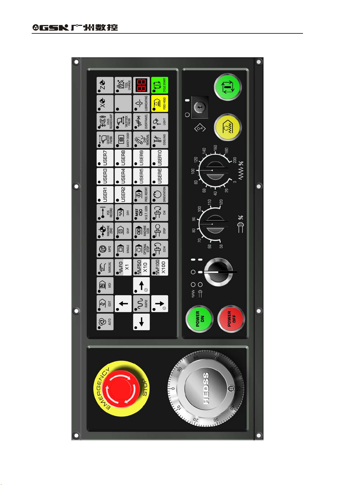
4.3 Control Operations on Panel
Fig.4-2 Operation panel
2
Page 7
Volume Ⅱ Chapter 4 Operation
4.3.1 Operation panel
The functions of the operation panel and the layout of switches on it vary depending on different
machine types, see machine user manual and the PLC manual of corresponding version for the
details.
The typical operation panel is shown in this manual(see the figure in previous page.)
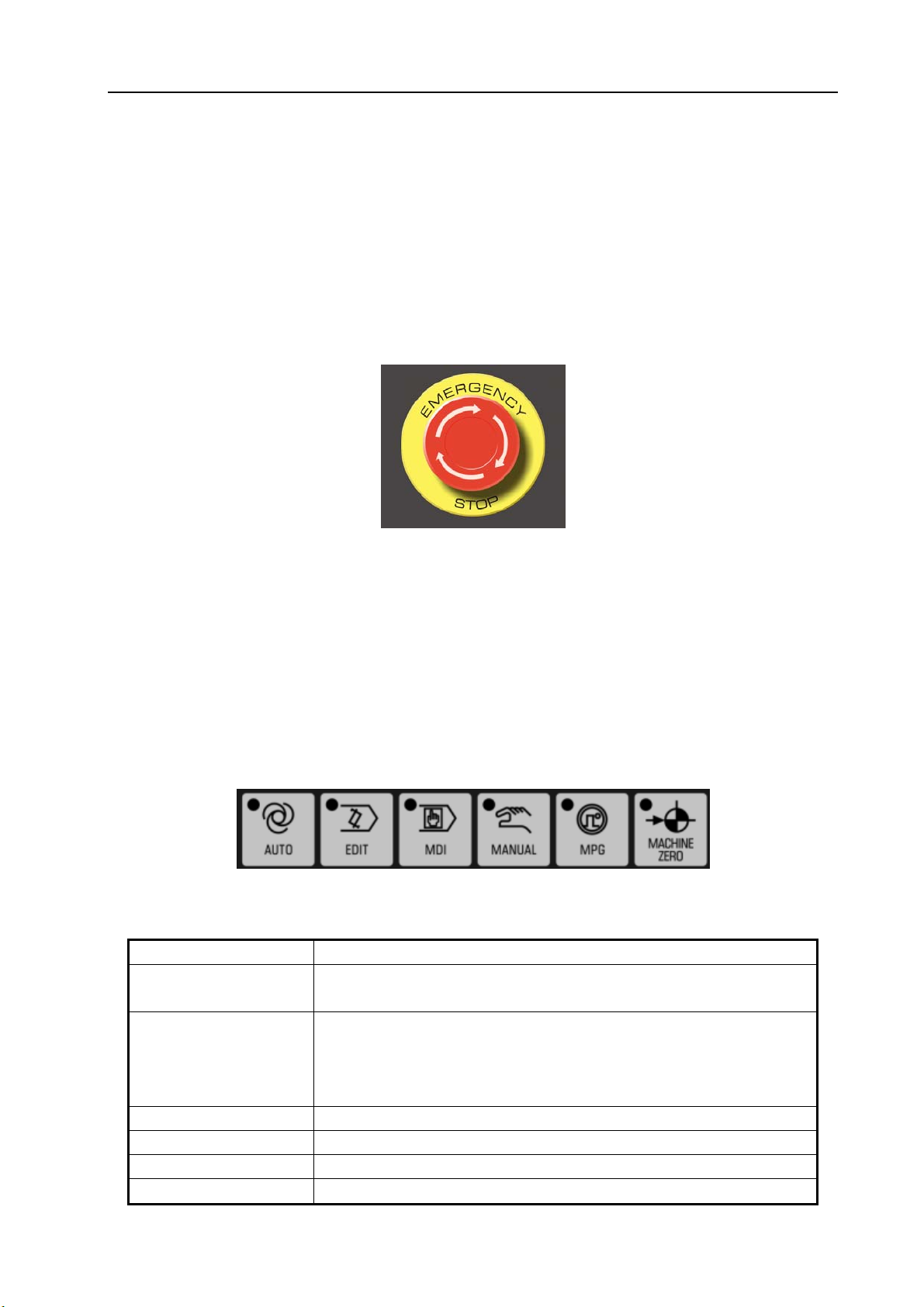
4.3.2 Emergency stop
In an emergency situation, by pressing the EMERGENCY STOP button, the movements of all
the machine axes are stopped immediately. At the same time, the button keep self-locked in the stop
position.
Fig.4-3 Emergency stop
The release of the button varies with different machine manufacturers. Generally, it is released
by rotating the button clockwise.
Note 1: The enable of the motor is cut off when this button is pressed.
Note 2: The control unit is reset.
Note 3: Make sure all faults are eliminated before releasing this button.
Note 4: Perform the reference point return by manual operations or G28 code after this button is released.
4.3.3 Mode selection
Operation modes available:
Fig.4-4 Mode selection
Table 4-1 Mode and Function
Mode Function
AUTO
EDIT
MDI MDI may be performed through MDI/LCD panel of the machine.
MANUAL For Jog feed
MPG For MPG feed
MACHINE ZERO For X, Z axes zero returns
(1) For execution of the programs in the memory
(2) For the program sequence number search in the memory
For the following program editing:
(1) Saving programs in memory;
(2) Altering, inserting and deleting programs;
(3) Outputting the programs in memory.
3
Page 8
GSK983T Turning CNC System User Manual
4.3.4 Operations related with manual operation
The following manual operations are available by the switches, keys, handwheel etc. on the
panel.
4.3.4.1 Continuous Manual feed
Continuous Manual feed can move the machine.
(1) Select the “Manual” mode;
(2) Select the feederate ( feederate switch is vaiable only when the rapid traverse switch is OFF).
Fig.4-5 Jog federate selection (mm /min )
Table 4-2 Jog federate
Switch
position
0 0 0 0 0
1 1.0 0.04 0.02 0.508
2 1.4 0.055 0.028 0.711
3 2.0 0.079 0.04 1.02
4 2.7 0.106 0.054 1.37
5 3.7 0.146 0.074 1.88
6 5.2 0.205 0.104 2.64
7 7.2 0.283 0.144 3.66
8 10 0.394 0.2 5.08
9 14 0.551 0.28 7.11
10 20 0.787 0.40 10.2
11 27 1.06 0.54 13.7
12 37 1.46 0.74 18.8
13 52 2.05 1.04 26.4
14 72 2.83 1.44 36.6
15 100 3.94 2.00 50.8
16 140 5.51 2.80 71.1
17 200 7.87 4.00 102
18 270 10.6 5.40 137
19 370 14.6 7.40 188
20 520 20.5 10.40 264
Note 1: The numerical values listed in above table vary with different machine builders.
Note 2; The error of the feedrates listed in the above table is approximately ±3%.
Lead screw for feed in metric system Lead screw for feed in inch system
mm /min Inch /min Inch /min mm /min
Jog feedrate
4
Page 9
Volume Ⅱ Chapter 4 Operation
(3) Select the moving axis
Press the direction key corresponding to this axis, the tool moves in the selected direction.
Fig.4-6 Select the moving axis
Note1: Two axes can be controlled simultaneously by Manual operation.
Note2: After power on, if the tool don’t move by the selected axis even the Mode selection is preset to
“MANUAL” position with an axis selected. Now it is necessary to reselect an axis.
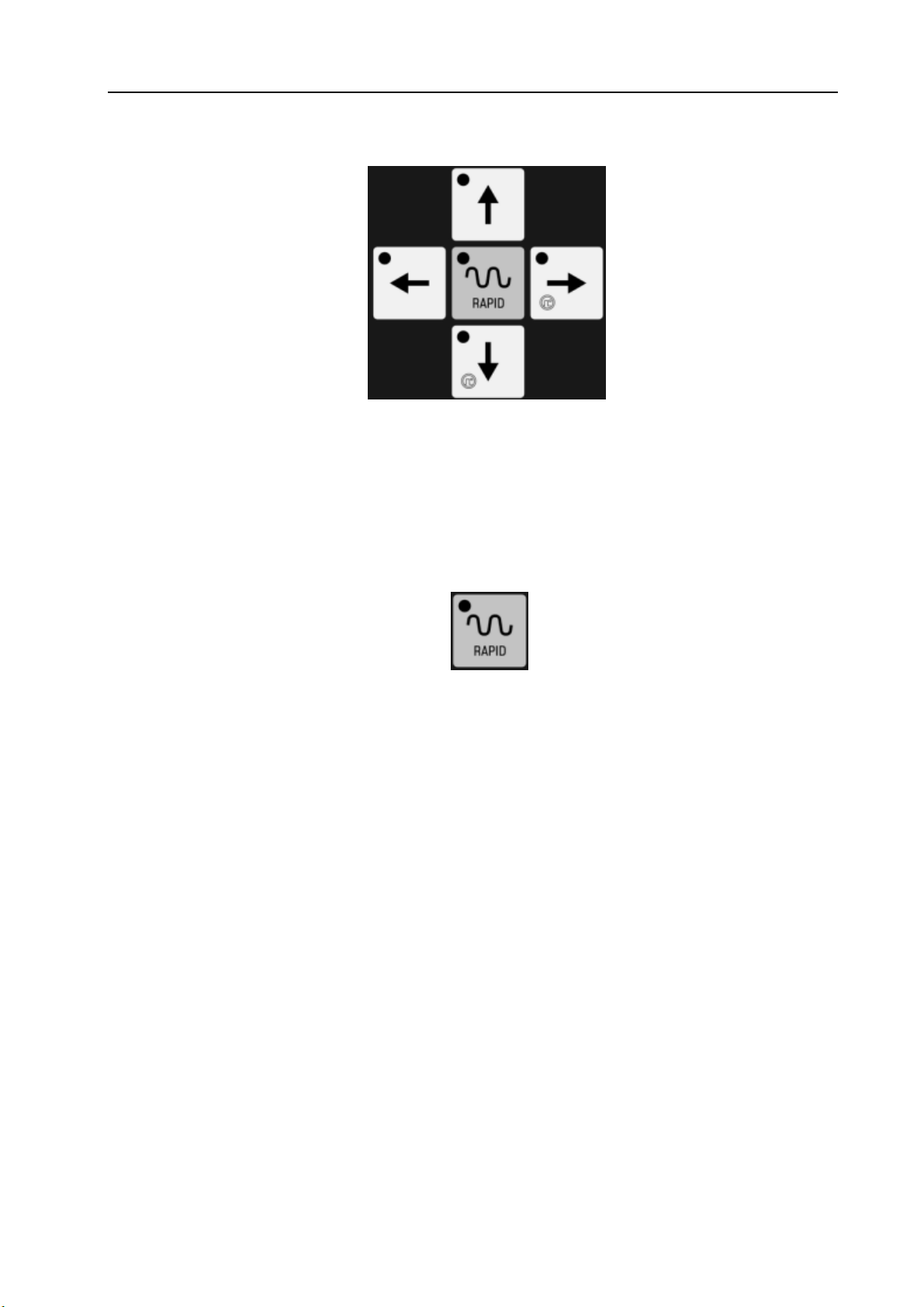
(4) Rapid traverse
An axis rapidly traverses in the selected direction when this key is pressed.
Fig.4-7 Rapid traverse
Note 1: The time constant and acceleration/deceleration mode for JOG rapid traverse are the same as
that of by G00 code ( it is set by machine tool manufacturer ).
Note 2: The federate of JOG rapid traverse can be set as 0.25 times ,0.5 times or 1 time of the speed
specified by G00. F0 is set by system parameter NO.113 ( it is set by machine tool
manufacturer ).
Note 3: When the machine has a storage type travel limit selecting function (parameter No.9.0 ISOT ), for
an axis with the function of reference point return, if the [RAPID] key is pressed after power on
or emergency stop, the feedrate will not change into rapid rate but maintain at a Jog feedrate
provided that the reference point return is not performed.
This is because storage type travel limit does not take effect before the manual reference point return,
thereby preventing the machine from quickly reaching the end of travel.
4.3.4.2 MPG
Accurate adjustment for the rate of the machine feed and move can be done with a manual pulse
generator(MPG).
(1) Select the MPG mode;
(2) Select a move amount
5
Page 10
GSK983T Turning CNC System User Manual
Fig.4-8
Amount of move: X 1 means move is multiplied by 1; while ×10 is by 10; while ×100 is by
100.
Table 4-3 Each step move amount
Input system
The move amount each step
×1 ×10 ×100
Metric system 0.001 mm 0.01 mm 0.1 mm
Inch system 0.0001 inch 0.001 inch 0.01 inch
(3) Select a move axis: press X or Z axis move key (either + or - direction)
(4) Turn the handwheel of the manual pulse generator.
Clockwise……………….+ direction
Counter clockwise………- direction
(The rotating direction depends on the settings of the machine builders)
Note 1; If the MPG rotates at a speed over 5 turns per second, the amount of the rotation of the MPG will
differ from the move distance of the machine. Hence do not rotate the MPG too quickly.
Note 2: Incremental feed function is not required if MPG is fixed on the machine.
Note 3: When ×100 override is selected and the MPG is turned at quick speed to make the tools or work table
move at “rapid traverse” rate, the machine will be subject to impact if it is stopped abruptly. The
selection automatic acceleration/deceleration function is also active for JOG feed, thereby it may
reduce mechanical shock.
Note 4: See section 4.3.7 for the MPG insertion function.
4.3.4.3 MANUAL ABSOLUTE ON/OFF
MANUAL ABSOLUTE ON/OFF is used to define whether the move amount because of JOG
operation is added to the automatic axis coordinate. When it is ON, the move amount is added to the
coordinate system, or else, not.
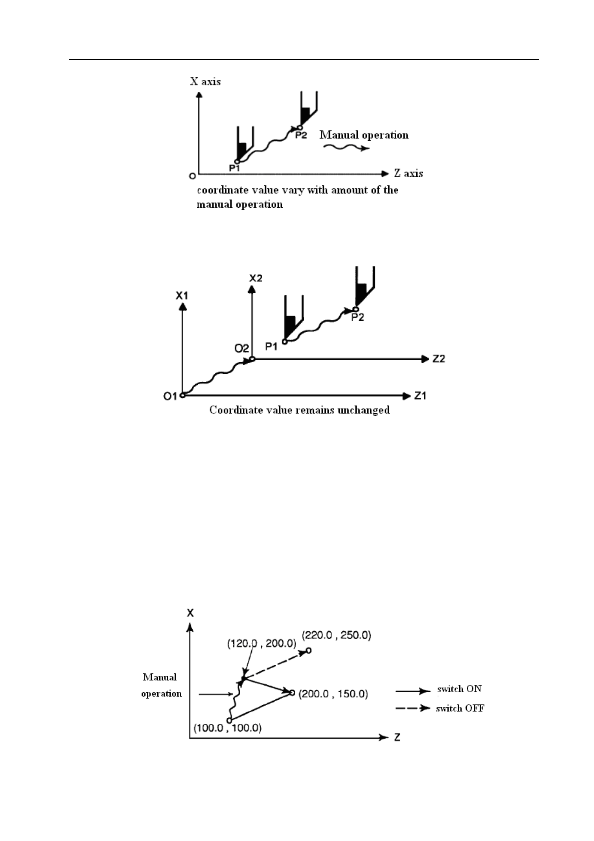
(1) MANUAL ABSOLUTE switch ON : Coordinates vary with the manual operation.
6
Page 11
Volume Ⅱ Chapter 4 Operation
Fig.4-9
(2) MANUAL ABSOLUTE switch OFF: Coordinates do not vary with the manual operation.
Fig.4-10
The following example shows the relationshiop between MANUAL ABSOLUTE ON/OFF and
coordinate:
G01 X100.0 Z100.0 F100; (1)
X200.0Z150 ; (2)
X300.0Z200.0 ; (3)
(A) Manual operation after block end
The manual operation (move by +20.0 in X direction and +100.0 in Z direction) will be
performed while the block (1) ends, and then block (2) will be executed.
Fig.4-11
7
Page 12
GSK983T Turning CNC System User Manual
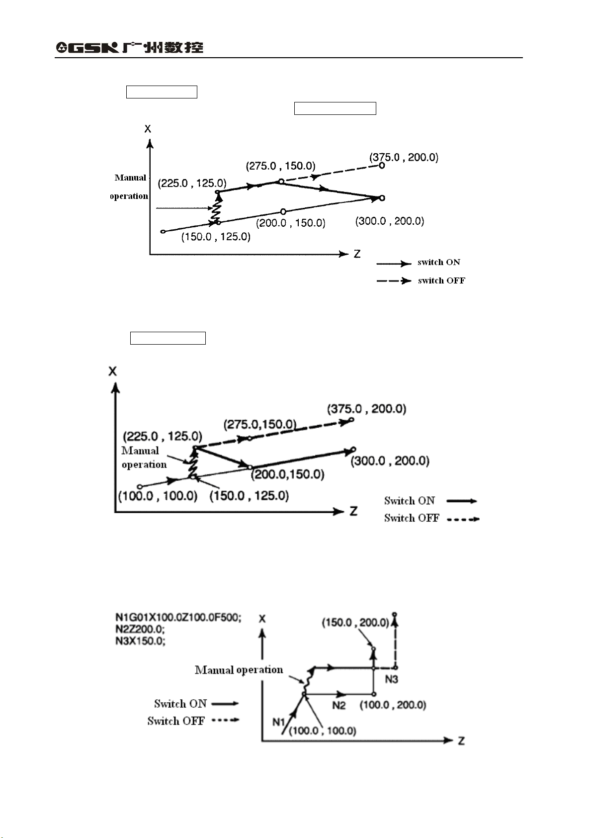
(B) Manual operation after FEED HOLD
Press the FEED HOLD key in the execution of the block (2). After manual operation (X+75.0),
re-execute the the coordinate value while pressing CYCLE START key .
Fig.4-12
(C) When Manual operation after FEED HOLD is followed by Reset
Press the FEED HOLD key in the execution of the block (2). Reset the machine and
re-execute the block (2) after manual operation (X+75.0).
Fig.4-13
(D) When a single axis is specified in the move command of the next block
When a single axis is specified in the following command, only the axis specified returns.
Fig.4-14
8
Page 13
Volume Ⅱ Chapter 4 Operation
(E) Manual operation during tool nose radius compensation
When the next block is an incremental command, then the action is identical with that is
commanded while the MANUAL ABSOLUTE switch is set to ON or OFF.
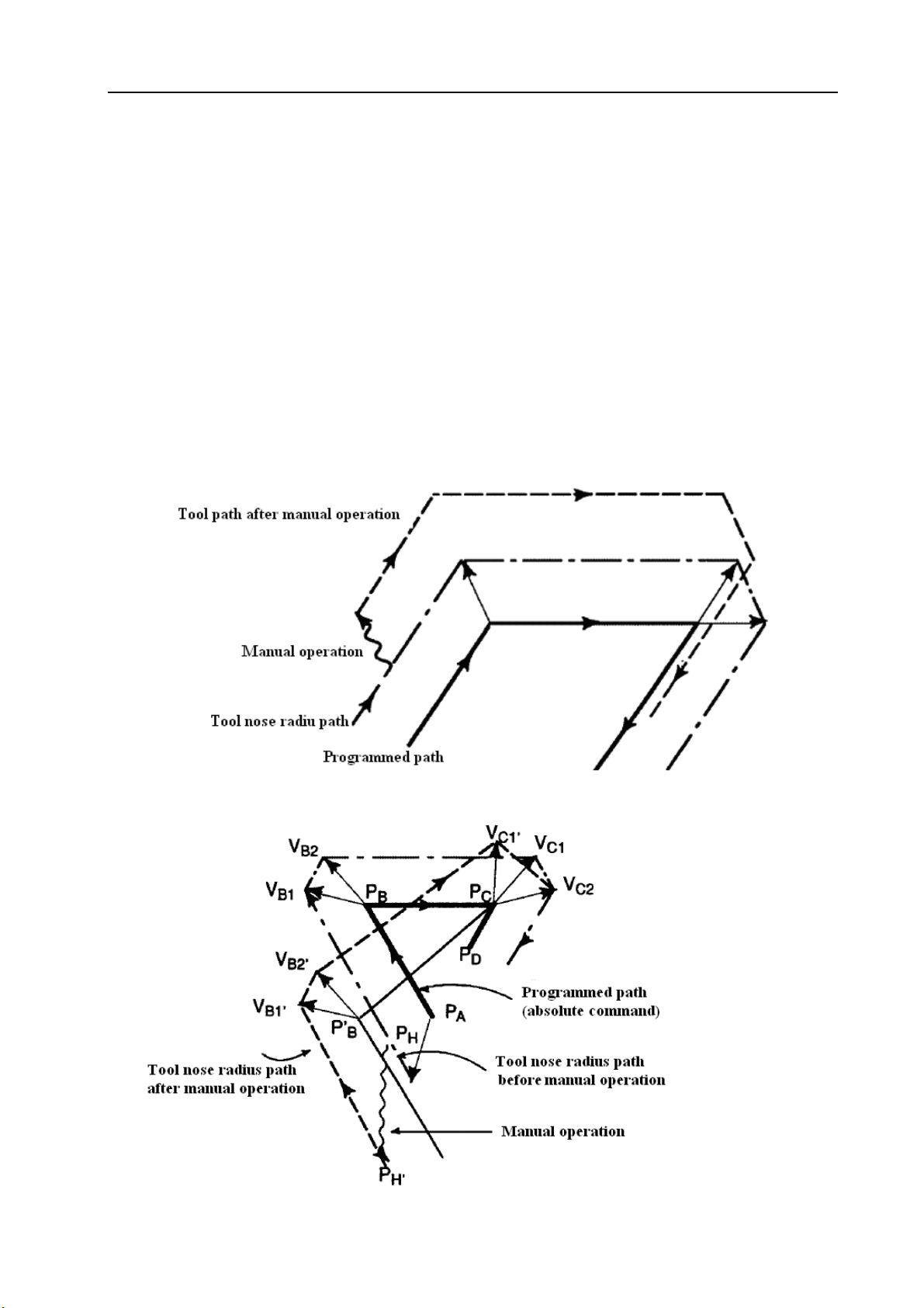
(F) Manual operation during tool nose radius compensation
If MANUAL ABSOLUTE switch is switched OFF:
If manual operation is executed when MANUAL ABSOLUTE switch is switched off during tool
radius compensation, the tool will move along the tool path wihich parallel to that without manual
operation in the restarting auto mode. The parallel space equals to the move amount in manual
operation.
If MANUAL ABSOLUTE switch is switched ON:
If MANUAL ABSOLUTE switch is set for ON for manual operation in the tool nose radius
compensation mode, the automatic running path of the tool by absolute command after restart is as
follows. The vectors set in the rest of the block and the origin of the next block will be offset parallelly.
Tool path is determined by the vector between the next block and the block that follows as well as
the move amount generated by manual operation. This is also applicable for the case by manual
operation during corner.
Fig.4-15
Performing manual operation when no corner
Fig.4-16
9
Page 14

GSK983T Turning CNC System User Manual
In the above programmed path (PA→PB→PC→PD), the tool is moved from the point PH between
P
and PB to point PH′ by manual operation provided the FEED HOLD key is pressed. due to the
A
offset as a result of manual operation and the vectors VB1 and VB2 of point PB also offset to V
V
The vectors between the next block tha (tool path from PB to PC) and the one that follows (from PC
B2’.
) do not need compensation. The new vectors VC1′ and VC2′ will be generated according to the
to P
D
B1’
and
relationship between the two blocks (in this example VC1′ =VC2′). Since vector VB2′ is not
re-calculated, however, the section of path between PB’ and PC as a result of tool offset is not
accurately performed. But for the block after point P
, tool nose compensation can be precisely
C
performed.
Performing manual operation during the executin of corner
Fig.4-17
The above figure is an example for the manual operation during execution of corner. the vector
V
, V
A2′
and V
B1′
in above figure respectively parallel to the vectors VA2, VB1 and VB2 by a jog move
B2′
amount. And the new vectors is generated according to VC1 and VC2′. The blocks after point P
be precisely executed by the tool nose radius compensation
Manual operation after single block end
will
C
10
Fig.4-18
Page 15
Volume Ⅱ Chapter 4 Operation
Perform the manual operation after the execution of a single block,
If manual operation is performed after the execution of a single block, the vectors VB1 and VB2
offste the move amount by JOG operation. And the method for the following tool path is identical with
that mentioned above. MDI operation may be inserted just like the JOG operation. The tool path after
MDI operation coincides with that after the insertion of a manual operation.
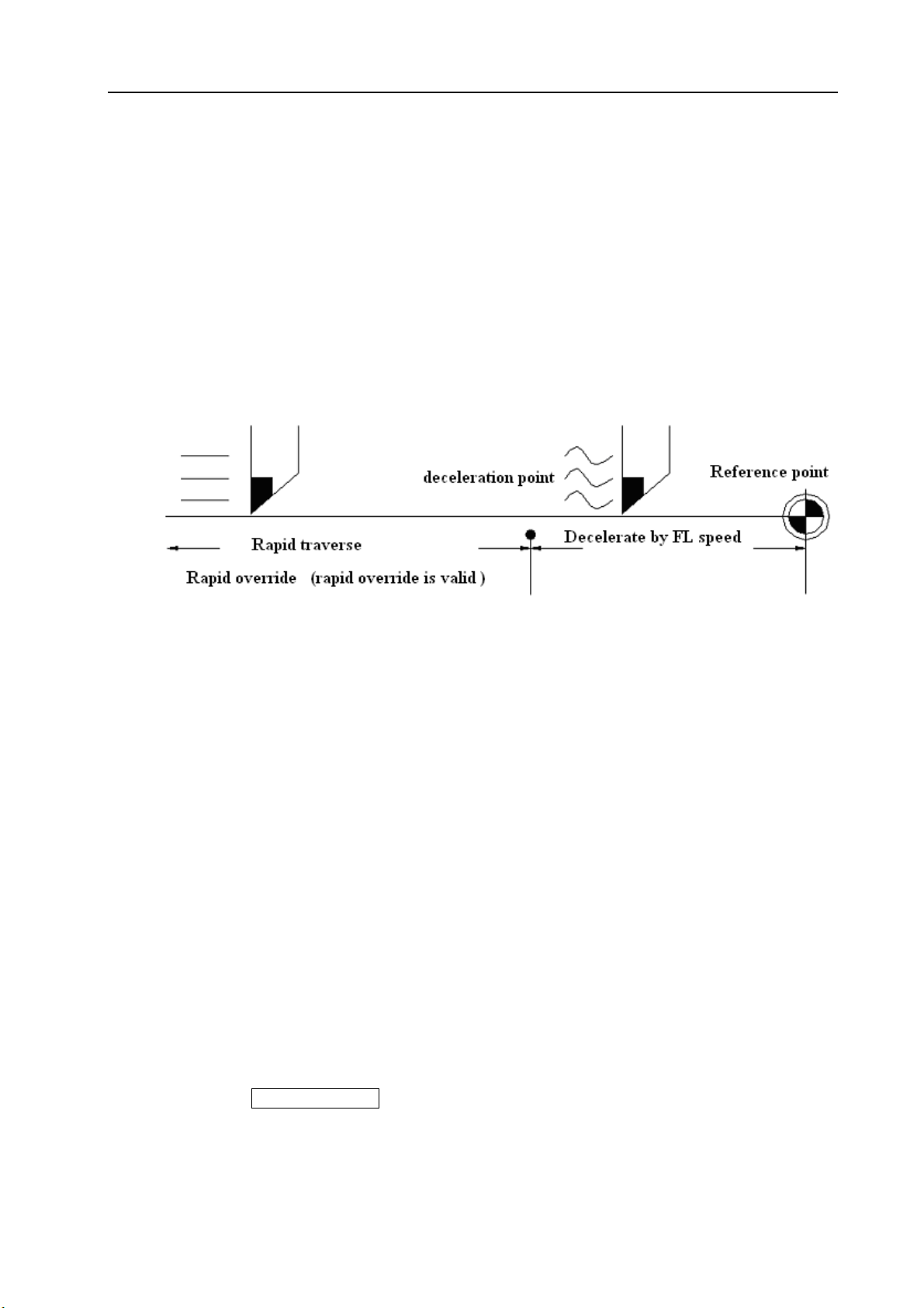
4.3.5 Manually returning to reference point
The tool may be returned to the reference point by manual operation:
(1) Select “MACHINE ZERO” mode;
(2) Press ”ZERO” axial direction key, the machine enter zero self-insurance state and the state will
not be cancelled until arrive at the reference point, of course, the state also can be cancelled by
pressing EMERGENCY or RESET key in the midway.
Fig.4-19
Note: The speed of FL is set by parameter No.114 ( set by machine manufacturer)
(3) The machine stops at the reference point indicating the end of the return and the LED lights
for X ZERO/Z ZERO on the panel light up.
Note 1: The following procedures may set the LED light for the reference point return over to OFF:
(1)Move away from the reference point.
(2)Enter emergency stop state.
(3)Servo alarm.
Note 2: For the distance to the reference point return, please refer to machine user manual issued by
machine tool manufacturer.
4.3.6 Operations on automatic running
The machine may operate automatically by commands. The steps are as following:
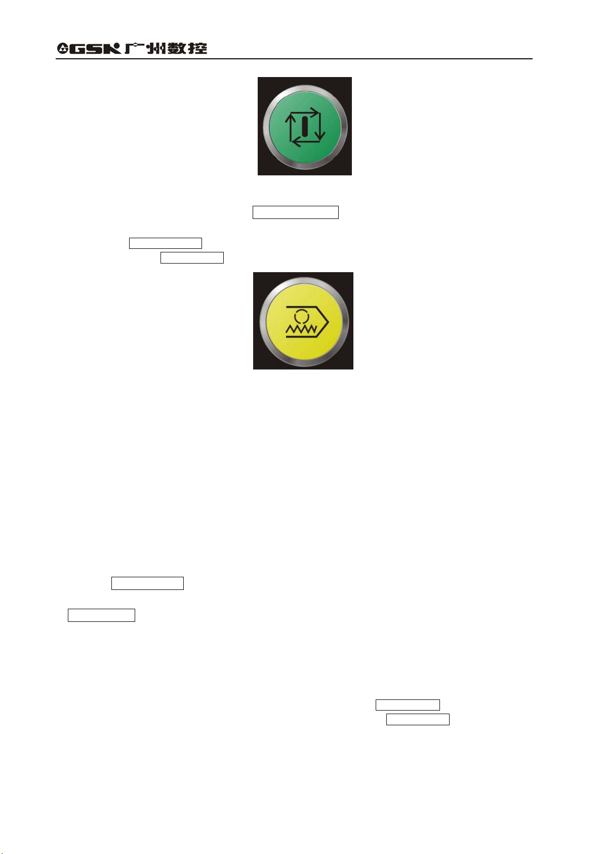
4.3.6.1 Start of automatic running
Procedures for starting the program stored in memory:
(Ⅰ) Select the program number, see Section 4.4.14 “ program number search”;
(Ⅱ) Select the AUTO mode;
(Ⅲ) Press the CYCLE START key.
11
Page 16
GSK983T Turning CNC System User Manual
Fig.4-20 Cycle Start
Automatic running starts once the CYCLE START key is pressed. And the LED light for
CYCLE START lights up.
Note: The CYCLE START key is inactive or cancelled in the following conditions:
(a) When the FEED HOLD key is pressed;
Fig.4-21 Feed Hold
(b) When the EMERGENCY STOP button is pressed;
(c) When the RESET signal is enabled (contact the machine builder for details);
(d) When the “Mode selection” button is set to a wrong position (except AUTO, DNC and MDI
modes);
(e) When it is searching a sequence number;
(f) When an alarm is given;
(g) When automatic running is being performed (not in feed hold or stop state);
(h) When the NC system is not ready.
4.3.6.2 Dwell of automatic running
Press FEED HOLD key:
The CYCLE START LED light is gone out and the FEED HOLD LED light lights up when the
FEED HOLD key is pressed. Now:
(I) If the tool is moving, the feed slows down and stops;
(II) If the machine is in G04 dwell state, the dwell state will not continue ;
(III) The machine stops after the of M, S, T codes are executed.
Note: In case of the thread cutting commanded by G32, G34, G76 or G92 (special G code B: G33, G34,
G76 or G78; special G code C: G33, G78 or G21), even the FEED HOLD key is pressed, the
feeding will not stop until the cutting is finished.However, if the FEED HOLD key is pressed as
the thread cutting cycle is being executed, the tool retractes by slant and returns to the start point
of cycle.
12
Page 17
Volume Ⅱ Chapter 4 Operation
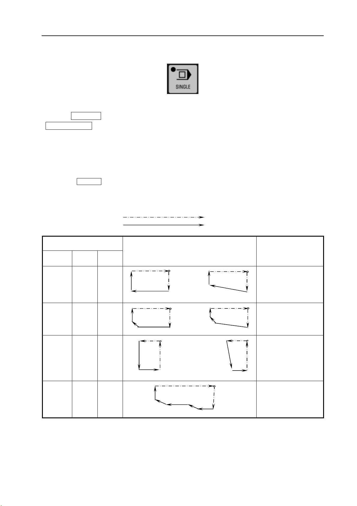
4.3.6.3 Single block
Fig.4-22 Single block
If the SINGLE key is pressed, the control only executes a block and stops each time when the
CYCLE START key is pressed .
(1) reference point return and single block commands
If the reference point return commands G28~G30 are executed, the single block is enabled at
the intermediate
(2) single block during canned cycle
The stop points of the single block In the canned cycle are as follows:
If the SINGLE key is pressed, the actual running paths for the canned cycle G90, G92,G94 or G70~G76
(special G code B: G77, G78, G79 and G70~G76; special G code C: G20, G24, G21 and G72~G78) are as
following:
Rapid traverse
Feeding
point.
Table 4-4 Tool path
G code
Standard
G90 G77 G20
G92 G78 G21
G94 G79 G24
G70 G70 G72
Special B Special
C
Tool path Explanation
4 4
3 1 3
1
2 2
Assuming tool path from
segment 1 to 4 is a cycle,
and it stops when the
segment 4 is finished
4 4
3 1 3
As above
2 2
1 1
2 4 2
As above
4
3 3
7
1
5
6
4
3
2
Assuming tool path from
segment 1 to 7 is a cycle,
and it stops when each
7-segment is finished
13
Page 18

GSK983T Turning CNC System User Manual
G71
G72
G71
G72
G73
G74
Note The path in this figure is all the same for
G71 or G72 code.
G73 G73 G75
G74
G75
G74
G75
G76
G77
Note The path in this figure is all the same for
G74 or G75 code.
3
7
11
15
4
2
8
6
12
10
16
19
14
19
1
5
9
13
17
Assuming tool path from
segment from 1 to 4, 5 to
6, 9 to 12, 13 to 16, 17 to
20 is a cycle, and it stops
when each cycle is
finished.
6
5
4
3
1
2
Assuming tool path from
segment 1 to 6 is a cycle,
and it stops when each
6-segment is finished.
9
8
5
7
6
4
10
1
3
2
Assuming tool path from
segment 1 to 10 is a
cycle, and it stops when
the segment 10 is
finished.
G76 G76 G78
4
3
1
2
Assuming tool path from
segment 1 to 4 is a cycle,
and it stops when each
4-segment is finished.
(3) Subprogram calling and single block running
For the blocks of M98P__, M99, G65, G66 or G67, the stop of the single block is inactive. However, it is
active if the addresses other than O, N, L and P codes are commanded together with M98 or M99 code.
4.3.6.4 Restart after feed hold or stop
(1) Select the AUTO or MDI mode in the feed hold;
(2) Press the CYCLE START key. The FEED HOLD indicator light is gone out and CYCEL
START indicator light lights up.
4.3.6.5 Manual operations in auto running
In auto run, make the operation to pause by pressing the FEED HOLD key or the SINGLE
key on the operation panel.
(1) Record the coordinates of the stop position displayed by the position display unit.
(2) Perform manual operation (see Section 4.3.4).
(3) Return the tool to the recorded coordinates (the start point of manual operation).
(4) Set the working and mode to be that before manual operation so as to restart auto
running.
(5) Press the CYCLE START key.
14
Page 19
Volume Ⅱ Chapter 4 Operation
4.3.6.6 MDI operations in auto running
(1) Press the SINGLE key, the single block is active, execute a block and stop;
(2) Select “ MDI ” mode;
(3) Perform MDI operation;
(4) Select the primary working and mode and press the CYCLE START key on the
operation to restart auto running
Note 1: The MDI command is influenced by modal data reserved in auto running.
Note 2: The modal data commanded by MDI will be active in auto running.
Note 3: Tool nose radius compensation R is unallowed in MDI operation.
Note 4: The auto running will be paused if FEED HOLD button is pressed in the execution of a block, and it
cann’t be restarted by MDI command.
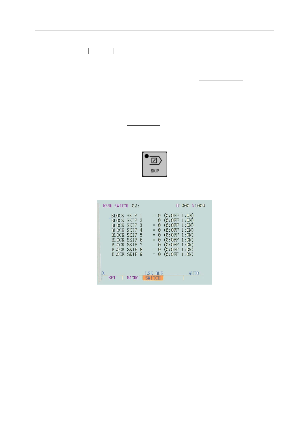
4.3.6.7 Skipping over optional blocks
Fig.4-23 Skip block
This function is used to make the control to skip over the block headed with “/”.
Fig.4-24
When the “/” is defined to be followed by a numeral, and the BLOCK SKIP SWITCH on the
operator panel of machine is set to “ON”, in the memorizer working, the information is ignored which
is contained in the block /n corresponding to the specified BLOCK SKIP number n.
When the BLOCK SKIP SWITCH on the operator panel of machine is set to “OFF”, the
information of the block specified by /n is active. That means the operater can determine whether to
skip over the block containing /n.
The 1 in the character /1 can be ignored. However, if two or more BLOCK SKIP SWITCH are
used for one block,it can not be ignored.
Example:
( incorrect ) ( correct )
//3G100×10.0; /1/3G00×10.0;
The function is ignored when the program is inputed into the memory, and the block containing
/n is stored into it regardless of the setting of BLOCK SKIP SWITCH.
15
Page 20
GSK983T Turning CNC System User Manual
The block stored in the memory can be outputed regardless of the setting of BLOCK SKIP
SWITCH. The BLOCK SKIP is active even in the operation of sequence search.
The number of BLOCK SKIP SWITCH on the operator panenl is different for different machines,
for the details, please see the machine user manual. The BLOCK SKIP on the operator panle is
generally set to be BLOCK SKIP 1.
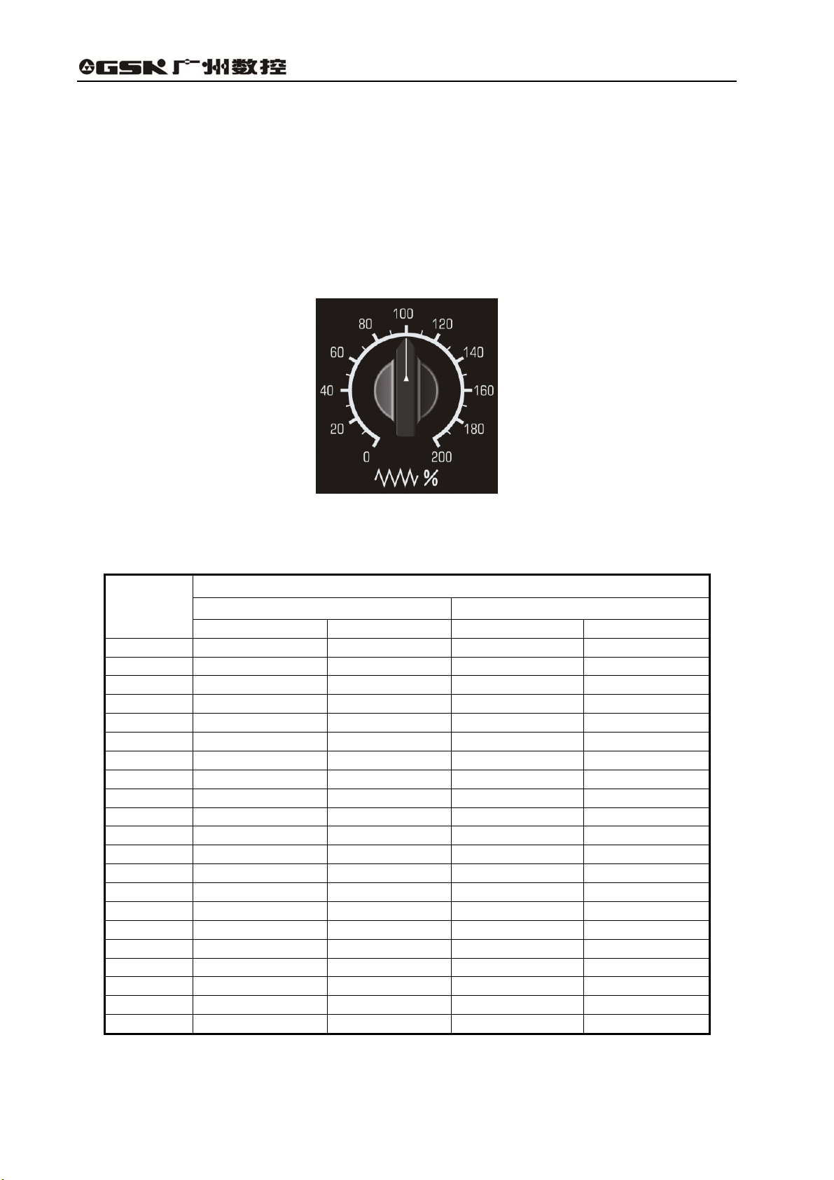
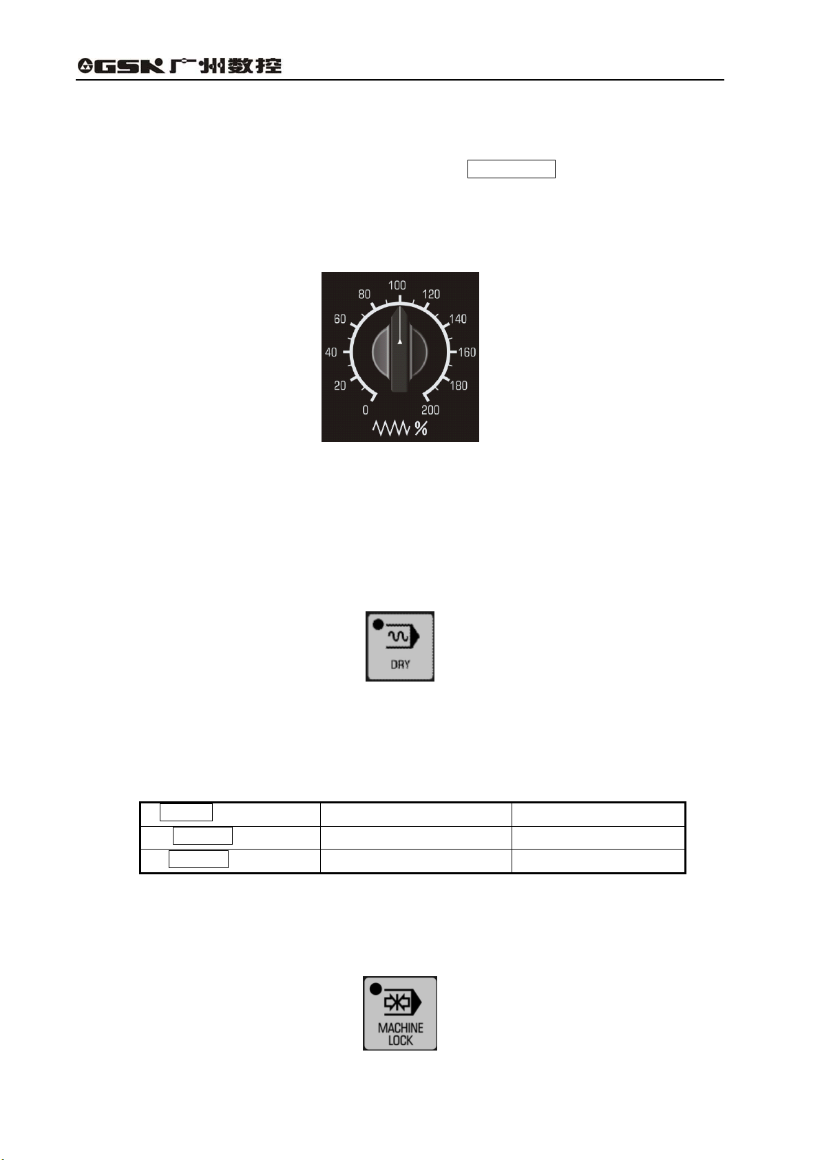
4.3.6.8 Feedrate override
The programmed feedrate may be multiplied by override.
Fig.4-25 Feedrate override
The programmed feederate multiplied by the override 0~200% of corresponding scale and the
increment is 10%.
Note 1: This switch is used together with the JOG feedrate for some machine builders.
Note 2: This switch is inactive in thead cutting and its override is usually 100%.
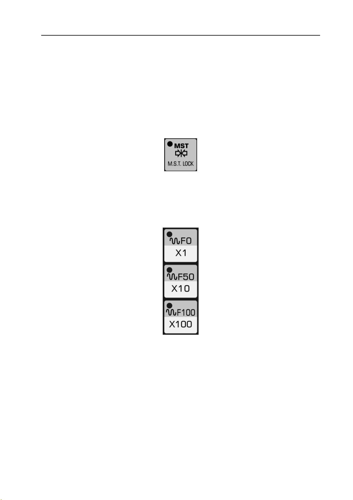
4.3.6.9 Dry run
Fig.4-26 dry run
If the dry run is active in the cycle running in the memory or commanded by MDI, then F function
is disenabled, and the control may move at the following speed:
Table 4-5
RAPID key ON/OFF
RAPID key ON
RAPID key OFF
Note 1: Wether the dry run is enabled in the rapid feed is set by parameter No.6.0 (RDRN).
Note 2: Wether the dry run in threading is disabled or enabled is set by parameter No.8.0 (TDRN).
Rapid traverse Cutting feed
Rapid traverse Maximum Jog feedrate
Jog feedrate (see Note ) Jog feedrate
4.3.6.10 Machine Lock
16
Fig.4-27 Machine lock
Page 21
Volume Ⅱ Chapter 4 Operation
When the MACHINE LOCK switch on the frame is set to be “ON” or that on operator panel is
active, the move command pluse will be repressed. Therefor, the position display of feed cycle start
or manual operation will be refreshed by the command inputed, however, the carriage doesn’t move
in the program execution, and the machine coordinates don’t change either. This function is used to
check program.
Note 1: When G27, G28 or G30 command is set, the machine will not return to the reference point. Hence the
indicator light for reference return is not lit up.
Note 2; M, S, T functions are performed.
4.3.6.11 Auxiliary Lock
Fig.4-27 Auxiliary Lock
When the AUXILIARY LOCK is ON, the machine carriage moves normally, but the M,S,T function
is not performed, this function is used to check program.
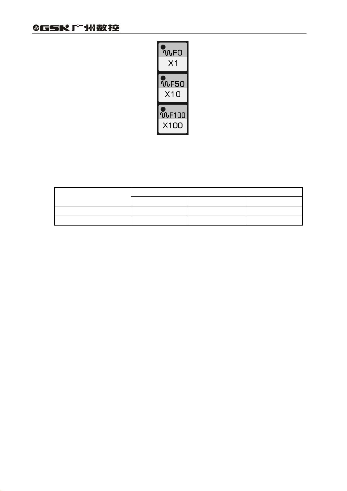
4.3.6.12 Rapid Override
Fig.4-28 Rapid Override
The rapid overrides F0, 50%, 100% are available on the operation panel of the machine. If the
rapid rate is 10m/min, and the override is 50%, then the rate becomes to be 5m/min. F0 is a fixed
speed (feedrate) specified by the machine builder.
This override applies to the following conditions:
(1) Determine the rapid rate of G00;
(2) Determine the rapid rate in canned cycles;
(3) Determine the rapid rate in G27, G28, G29 and G30 modes;
(4) Determine Jog rapid rate;
(5) Determine the rapid rate in manual reference point return.
17
Page 22
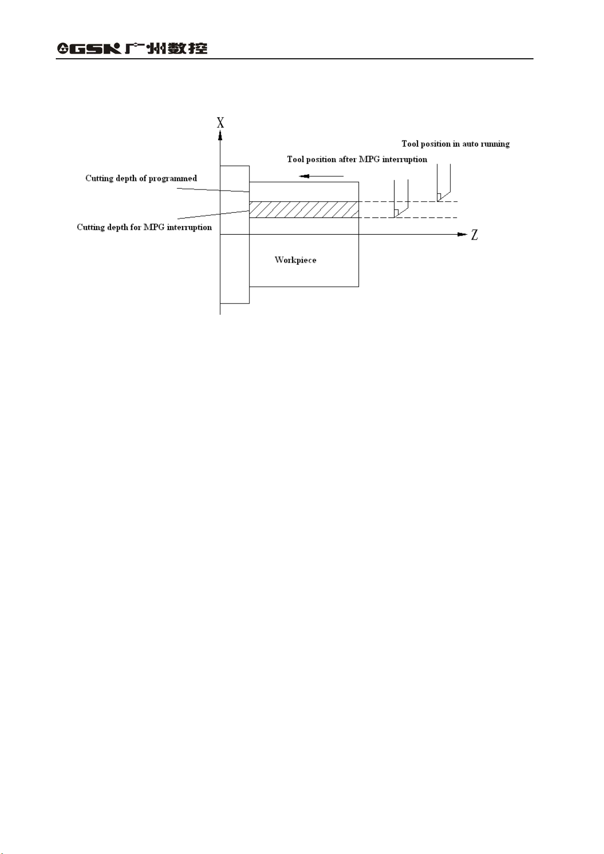
4.3.7 MPG Interruption
GSK983T Turning CNC System User Manual
Fig. 4-29
4.3.7.1 Summary
For the specific axis (set by parameter No.314.0 和 No.314.1) in auto running, it may be moved
manually by handwheel (MPG) to overlap the path in the auto running.
4.3.7.2 MPG (manual pulse generator) interruption
Manual interruption can be performed by turning the manual pulse generator in the following
conditions.
(1) Auto mode or MDI mode.
(2) Operating state: Manual insertion is possible during auto running and linear interpolation, arc
interpolation.
However, the following conditions are excluded:
(Ⅰ)When an alarm is being given;
(Ⅱ)When machine lock is active;
(Ⅲ)When positioning is valid;
(Ⅳ)When interlocking is valid;
(Ⅴ)No move command.
(3) Manual axis selection signal
Manual axis selection signals (HX , HZ) are powered up (contacts making) for the axis to perform
manual insertion.
4.3.7.3 Movement of manual insertion
(1)Amount of move
The amount of move by manual insertion is identical with that of the MPG feed. The amount of
move depends on the scale of the manual pulse generator and manual feed overrides (X1, X10 and
X100) and is added to that of automatic running.
18
Page 23
Volume Ⅱ Chapter 4 Operation
(2)Move speed:
The axial speed for manual insertion is the result of the addition of the move speed of auto
running to that by manual insertion. Therefore, axial speed will be limited to rapid traverse rate
(parameter #92(RPDFX)and #93(RPDFX)) in the event that axial speed exceeds rapid traverse rate.
Because the distance whose speed exceeds the rapid traverse rate is lost, the scale value displayed
on the MPG is invalid.
(3)The relations of manual insertion to various signals are as the following table:
Table 4-6
Signal Move
Machine locked
Displayed locked
Mirror image of X axis
(4)The relations of manual insertion to various signals are as following table:
It is affected, that is, the tool does not move if the
machine is set to ON
It is affected, that is, the relative coordinate does
not change if the display is locked
It is not affected, that is, machine moves positively
if hand disk is rotated in positive direction
Table 4-7
Display Move
Absolute coordinates
Not affected: Manual-inserted pulse is not added
to absolute coordinates
Relative coordinates Affected: Manual-inserted pulse is added
Machine coordinates Affected: Manual-inserted pulse is added
(5)Display of move amount
Move amount by manual insertion may be displayed by(DGNOS)key.
8 0 5
Manual-inserted move amount of Axis X
8 0
6
Manual-inserted move amount of Axis Z
Unit: 0.001mm (metric system)
0.0001inch(inch system)
Note: The move amounts may be cleared by clearing operation.
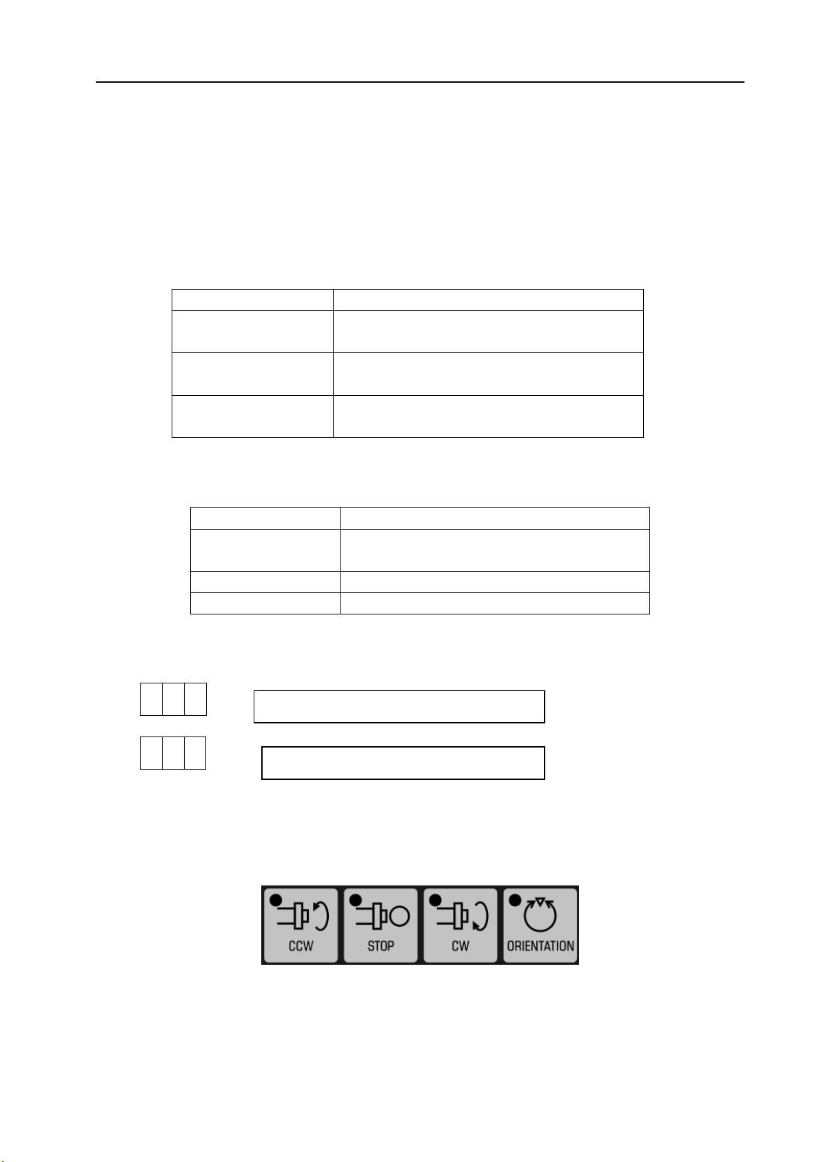
4.3.8 Manual spindle function
Fig. 4-29
Press SPINDLE CCW key in manual mode, spindle rotates CCW.
Press SPINDLE STOP key in manual mode, spindle decelerates to stop.
Press SPINDLE CW key in manual mode, spindle rotates CW.
19
Page 24
GSK983T Turning CNC System User Manual
Note:Actual rotational direction of spindle is different for various machines, please refer to machine tool builder’ s
manual.
Spindle orientation:Because the machine is matched with servo spindle driver, the system will send
orientation start signal to servo driver by pressing Spindle Exact Stop key in Manual mode or Auto, MDI
command M19. After spindle orientation is performed in the driver, completion signal is sent to CNC, and the
spindle orientation is finished. This function is used mainly for tool shifting and hole boring.
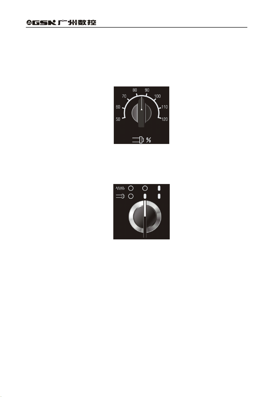
Spindle speed override:
Fig. 4-30
Spindle speed override can be adjusted from 50% to 120% by this switch.
4.3.9 Interlocking switch of spindle feed axis
Fig. 4-31
Position with 0 is OFF, and 1 is ON. In any states:
When feed axis and spindle are ON, feed axis and spindle interlocking are invalid.
When feed is off and spindle is ON, feed axis interlocking is valid and spindle interlocking is invalid. No.
2001 prompt appears in screen external information.
When feed axis and spindle are OFF, feed axis and spindle interlocking are valid. No. 2002 prompt
appears in screen external information.
20
Page 25

Volume Ⅱ Chapter 4 Operation
4.3.10 Manual miscellaneous function
Fig. 4-32
The functions and execution logic of these keys are defined by PLC programming. Please refer to
corresponding version of PLC manual. They control ON and OFF of each machine part separately. Usually,
press ON first and then press OFF. The functions of USER1~USER10 keys are not defined, which can be
defined according to user requirements.
Fig. 4-33
Tool shift key can be used for adjustment of manual tool change. Please refer to corresponding version of
PLC manual for details.
LED displays current tool No..
21
Page 26
GSK983T Turning CNC System User Manual
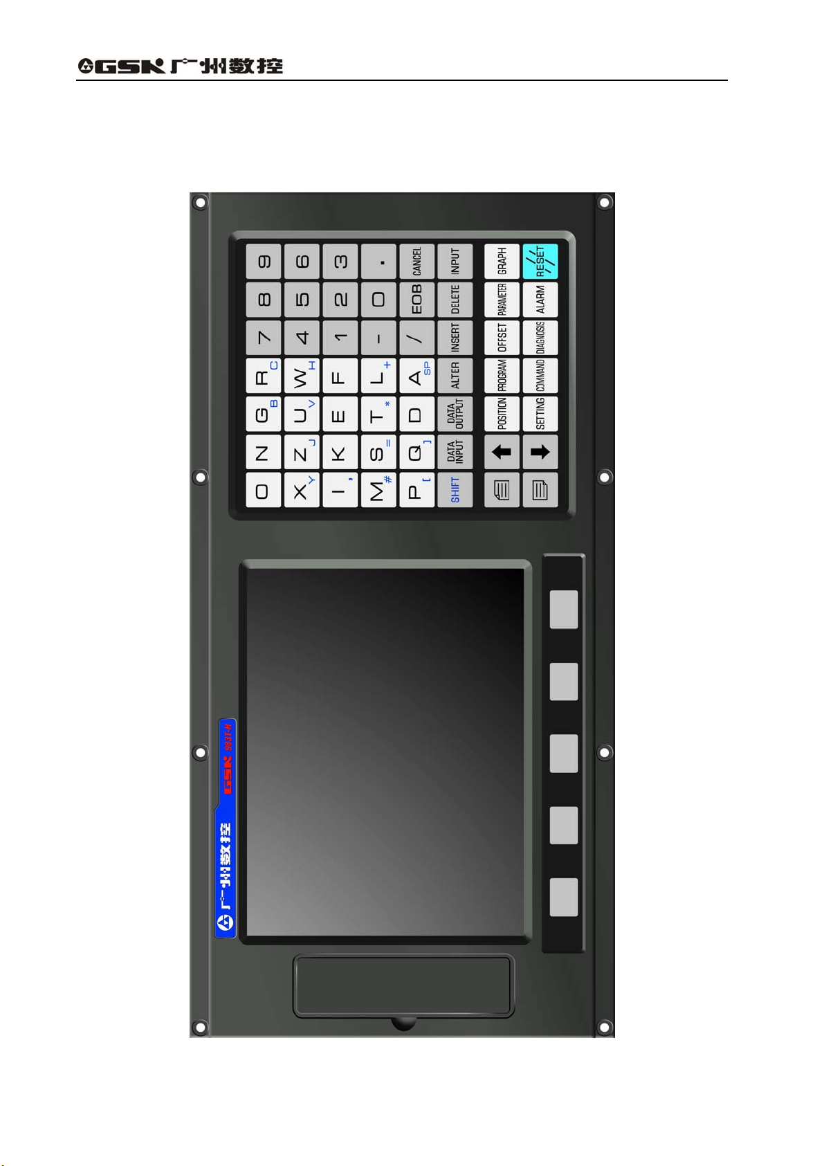
4.4 Operations and Display on MDI/LCD Panel
The MDI/LCD panel is usually placed at the upper front the device, and it is composed by the
LCD and keys as following figure shows:
22
Fig. 4-34
Page 27

Volume Ⅱ Chapter 4 Operation
Functional keys:
The large items displayed by the function keys are just like the chapters of a book. When a function
key is pressed for the second time or third time, the chapter 2 or 3 of the corresponding function is
displayed (if the function key for the chapter is provided).
Each chapter by functional keys includes several pages and each page may be selected with the
PAGE keys. The chapters and meanings for the functional keys are listed below.
Table 4-8
Pressing once Display of actual position and reset
Pressing once Display and setting of the set data
Pressing twice Display and setting of user macro program variables
Pressing for the
third time
Pressing once Display for program check
Pressing twice Display of the list of program numbers
Pressing for the
third time
Pressing once Display and setting of parameters
Display and setting of menu switch
Display the program
Pressing twice Display and setting of PC( PLC) parameters
Pressing once Display and setting of tool wear offset
Pressing twice Display and setting of workpiece coordinate system
Pressing for the
third time
Display and setting of tool contour offset
Pressing once Display of the information of an alarm
Pressing twice Display of an external alarm
Pressing once Display of command value and the commands input by MDI
Pressing twice Display of the information regarding program restart
Pressing once Display of NC diagnosis information
Pressing twice Display of the information regarding tool life management
Pressing once Display of the machining program tracking
Pressing twice
Setting of graph menu
23
Page 28
GSK983T Turning CNC System User Manual
In Chapter 1
Waiting for external data transfer, highest level interruption,
inactive for other function keys.
Transfer the system data to external, highest level interruption,
In Chapter 1
inactive for other function keys.
Note The screen display may be cleared by concurrently pressing a functional key and the CANCEL
key. And the corresponding screen display may be displayed when a functional key is pressed
then.
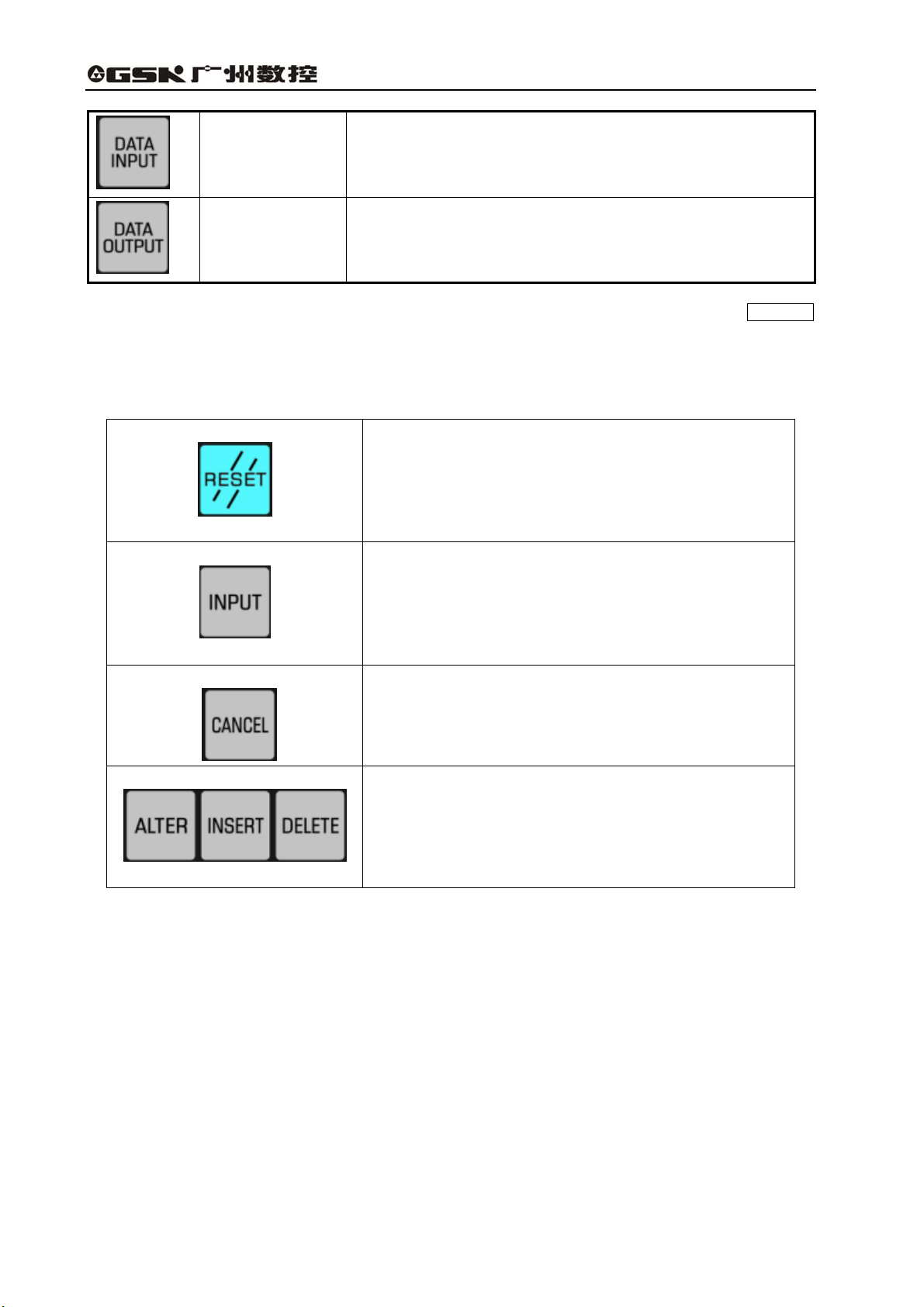
Table 4-9 Introduction for other keys on MDI keypad
Reset key
For CNC reset and alarm eliminating, etc.
Input key
When address key or numerical key is pressed, input data is
displayed on screen but it still in buffer. Press input key, and
these data are saved in register.
Cancel key
Edit key
Delete characters in buffer from the end by pressing cancel
key.
Alteration, insertion and deletion can be done by pressing these
three keys in keying in data.
24
Page 29
Volume Ⅱ Chapter 4 Operation
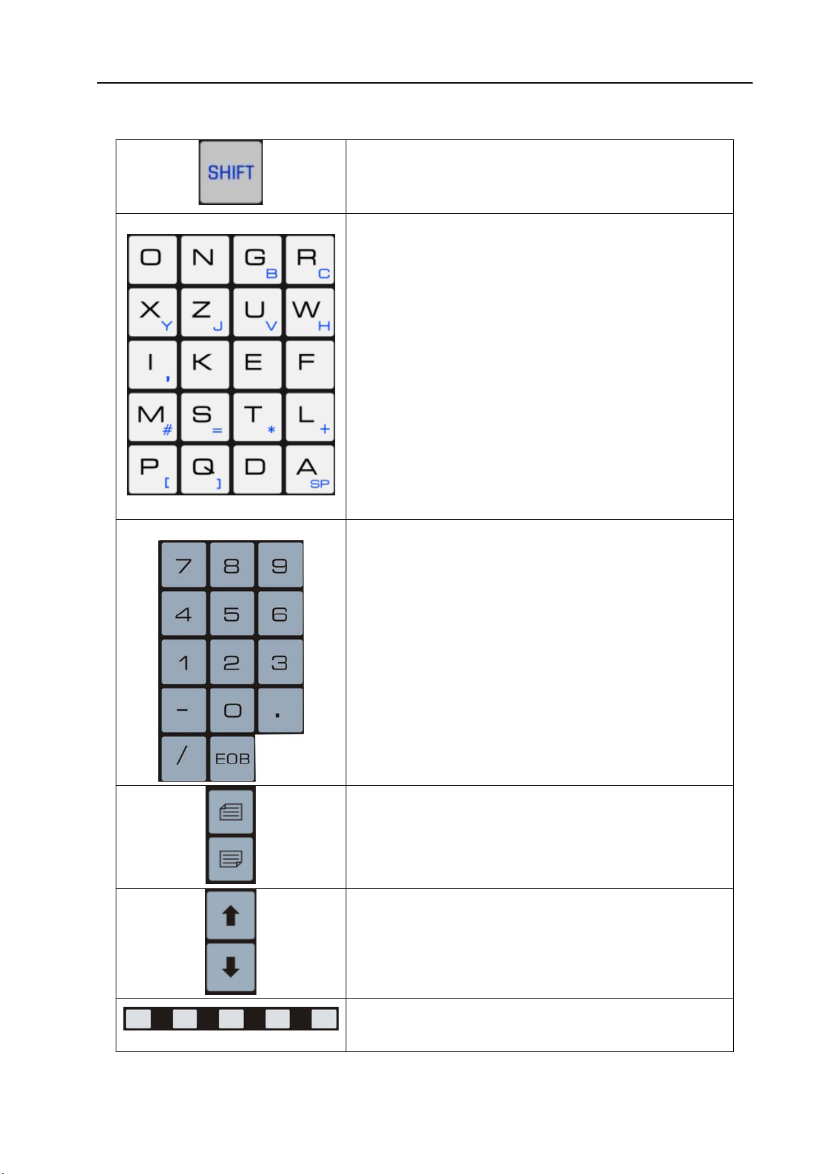
Table 4-9 Introduction for other keys on MDI keypad(continue)
Some address keys include two kinds of characters, which are
selected by pressing shift key. Input characters in the lower
Address key
right corner when sign “^”is displayed on the screen.
Input letters by pressing address key.
Numerical key
Digits and punctuation can be input by pressing numerical key.
Key in “;” by EOB key.
Page Up/Down:turn display screen forward or backward for
one page.
Cursor moving up or down.
Soft keys:its function is defined by the contents in the lower
part of the display screen.
25
Page 30
GSK983T Turning CNC System User Manual
4.4.1 Status display
The status indication of the system is displayed on the lower right part of the screen:
Fig. 4-35
The display for status is as follows:
NOT READY: It indicates that the control or servo system fails to operate.
LSK : It indicates the label skip mode created after power on or control reset other than MDI
mode.
BUF : It indicates that a block is read in but not executed. The blocks not executed are
eliminated after reset in modes other than MDI.
ALM : It indicates that an alarm is given. The alarm will be displayed (this symbol blinks) when
the ALARM key is pressed.
EDIT : It indicates that the editing function is being executed or is to be done..
As for the different position of the mode selection, besides the EDIT, there are modes such as
AUTO, MDI, HNDL, JOG, MACHINE ZERO (not displayed).
SRCH : It indicates the program number search is being executed (blinking).
RESTR: It indicates the period from the program restart to the last axis return is completed
(blinking).
4.4.2 Keys input display
The contents input by address keys or numerical keys are displayed at the lower left of the
screen.
Fig. 4-36
26
Page 31

Volume Ⅱ Chapter 4 Operation
Data cannot be keyed in when the POSITION or ALARM key among the function keys is
pressed to display a screen.
Only a word consisting of one address and a figure can be keyed in when program edit is not
being performed. Pressing CANCEL key once, this word may be cleared.
One or more words are not limited in program editing, a line of up to 32 characters can be
entered for a block.
The last entered character may be cleared by pressing the CANCEL key. If the CANCEL
key is pressed continuously, the typed characters will be cleared in succession.
Note: In Edit mode, program edit is enabled when the PROGRAM key is pressed.
4.4.3 Display of program number and sequence numbers
Program number and sequence numbers are displayed at the top of the screen as shown in the
following figure.
Fig. 4-37
4.4.4 Alarm display (functional key ALARM )
When “ALM” is indicated at right bottom of the screen in case of alarm, warning messages may
be shown through the following procedures:
Press the ALARM key, when the information about operation is displayed, press the
ALARM key again to display alarm message.
Refer to Appendix 7 for the meaning of the alarm number.
Fig. 4-38
Note: As a rule, alarm message automatically appears on the screen in the event of alarm.
27
Page 32

GSK983T Turning CNC System User Manual
4.4.5 Operation information
Table 4-10 Operation information
Mode Operation Contents
Excluded in case of the following
Other than EDIT
AUTO
EDIT
AUTO Program number search Display the program number searched
condition:
Sequence number search
Press ∧ key in PROG mode
Press ∧ key continuously in PROG
mode
Press ∧ key continuously in PROG
mode
In reset mode by pressing RESET
key
Once the machine sends out operation information, the information will be automatically
displayed on the screen.
Display last sequence number executed
Display random sequence number in
searching
Return to program home and display the
program number(return unallowed as
program being executed )
Review the program positively from the
memory current position and display the N
value that appears firstly
Review the program negatively from the
memory current position and display the N
value that appears firstly
Return to the current program home and
display the program number
Fig. 4-38
If operation information is needed after some other page is displayed, press the ALARM key.
External message is shown if the ALARM key is pressed again in this alarm page.
4.4.6 Current position display and reset (functional key POSITION )
(1) Press the POSITION key;
(2) Press the PAGE key. Data is displayed in one of the following three modes:
(Ⅰ) Position display in a relative coordinate system
28
Page 33

Volume Ⅱ Chapter 4 Operation
Fig. 4-39
Ralative position is displayed, once resetting, the position is cleared to zero.
Reset: By pressing the U or W key, the resetting may be done in this page. Address
code pressed will continuously blink. The relative position of the blinking address will be 0 if the
SHIFT key is pressed then.
(Ⅱ) Position display in a workpiece coordinate system
Fig. 4-40
It displays the current position of the automatic coordinate system set by G50, or by coordinate
system by reset.
Reset (program lock ON for active, OFF for inactive)
Reset: By pressing the X or Z key, the resetting may be done in this page. Address
code pressed will continuously blink. The absolute position of the blinking address will be 0 if the
SHIFT key is pressed then.
Note: Reset operation can only be performed during the stop of the auto running.
(Ⅲ) Display of the ALL position
The actual position may be displayed in the coordinate systems as following at the same time:
(a) Relative coordinate system
(b) Absolute coordinate system
(c) Machine coordinate system
(d) Distance to go
29
Page 34

GSK983T Turning CNC System User Manual
Fig. 4-41
DISTANCE TO GO indicates the remaining move amount of a block.
The positions in the coordinate systems cannot be reset in the ALL position interface.
4.4.7 Display of command value (functional key COMMAND )
(1) Press the COMMAND key.
(2) Press the PAGE key. The page is displayed in the following 3 modes:
(Ⅰ) It displays the command value being executed and the formerly commanded modal values.
Max. speed of constant surface speed
Speed by G96, G97
Actual speed
Fig. 4-42
Note: As shown in the above figure, the figure following character % stands for the feedrate that has been
multiply by overrided.
(Ⅱ) It displays the command value input by MDI or the command value to be executed.
30
Page 35

Volume Ⅱ Chapter 4 Operation
Fig. 4-43
(Ⅲ) It displays the command value of the next block to be executed during the tool nose radius
compensation R.
Fig. 4-44
4.4.8 Setting (functional key SETTING )
4.4.8.1 Display and setting of input, output, etc.
(1) Press the SETTING key;
(2) Press the PAGE key. Setting and display may be performed in the following two modes.
(I) Setting and display of input and output:
Fig. 4-45
31
Page 36

GSK983T Turning CNC System User Manual
Setting (execution unallowed when the program lock is disabled; or execution allowed when it is
disabled, whose state can be switched by parameter SETE)
(a) Set the mode selection to MDI mode.
(b) Press the cursor key ∧ , ∨ to move the cursor to the item to be altered. (The cursor
cannot be moved with the address key N .)
(c) Enter 1 or 0 by pressing the P 0 or 1 INPUT key as shown in the following table.
Table 4-11
Display
Item
TV CHECK Not do TV check Do TV check
PUNCH CKDE Output EIA code Output ISO code
INPUT UNIT mm input Inch input
INPUT DEVICE1 Standard set for 0
INPUT DEVICE2 Standard set for 1
Note 1: Unselected function cannot be set. For example, INCH=1 cannot be used for a metric-system
machine when metric/inch conversion function is not available. ISO=1 cannot be set when ISO
code input selection function is not available.
Note 2: INPUT UNIT is automatically rewritten when G20 (in inch system) and G21 (in metric system) code
is executed.
0
1
(II) Other settings and display
32
Fig. 4-46(a)
Fig. 4-46(b)
Page 37

Volume Ⅱ Chapter 4 Operation
Table 4-12 The displayed numbers and their meanings
Data No. Meaning
057 * Running time (Unit: hr) (TMHOR)
058 * Running time (Unit: min) (TMMIN)
059 * Running time (Unit: s) (TMSEC)
064 * Thread chamfering width (THDCH)
065 * Retraction amount of G74, G75 (GROVE)
066 * Finish allowance of G76 (THDFN)
067 * The retraction amount of G71, G72 (MRCDT)
068 * The minimum allowance of G76 (THCLM)
141 * Running time (TIME)
151 * X value of Acme 1 of storage travel limit 2
152 * Z value of Acme 1 of storage travel limit 2
153 * X value of Acme 2 of storage travel limit 2
154 * Z value of Acme 2 of storage travel limit 2
155 * X value of Acme 1 of storage travel limit 3
156 * Z value of Acme 1 of storage travel limit 3
157 * X value of Acme 2 of storage travel limit 3
158 * Z value of Acme 2 of storage travel limit 3
180 * Sequence number for corresponding stop
319 * Settings (PRG8,MSBL)
340 * Reserved
341 * Reserved
Note 1: The data numbers other than those listed in the above table are not displayed.
Note 2: The parameters are also set by the same data numbers.
Note 3: Please refer to the manual for details about the parameters that have the same data numbers.
Setting (execution unallowed when the program lock is disabled; or execution allowed when it is
disabled, whose state can be switched by parameter SETE)
(a) Set the mode selection to MDI mode.
(b) Press the cursor key ∧ , ∨ to move the cursor to the item to be altered. The cursor
cannot be moved with the address key N .
(c) Press address key P , numerical keys and INPUT key in succession to proceed.
4.4.8.2 Display and setting of user macro program variables
It is possible to display common variable values and the local variable values of the currently
called user macro program body on LCD.
33
Page 38

GSK983T Turning CNC System User Manual
Fig. 4-47
When a variable value is <null>, the display will be blank.(see chapter 3 10.2.3 <undefined
variable>)
When an absolute value is over 99999999, it displays OVER FLOW.
When an absolute value is not zero, but less than 0.0000001, it displays UNDR FLOW.
It displays:
(1) Select the set chapter 2 (Steps: press SETTING to display the setting page, and press it
again.)
(2) Since the display covers 6 pages, you need to press the PAGE key to display the required
page.
Page 1——Local variables #1~#20
Page 2——Local variables #21~#33
Page 3——Common variables #100~#119
Page 4——Common variables #120~#139
Page 5——Common variables #140~#149
Page 6——Common variables #500~#509
(3) Search variable number
Method 1 Press the cursor key and move the cursor ∧ , ∨ in succession. The
next page will be switched to once the cursor goes beyond the current page.
Method 2 Press N , variable number and INPUT key for inputting.
(4) Set variable number
(a) Select MDI mode;
(b) Key in P , variable number and INPUT when the variable is displayed and the
cursor is moved to the variable number to be changed.
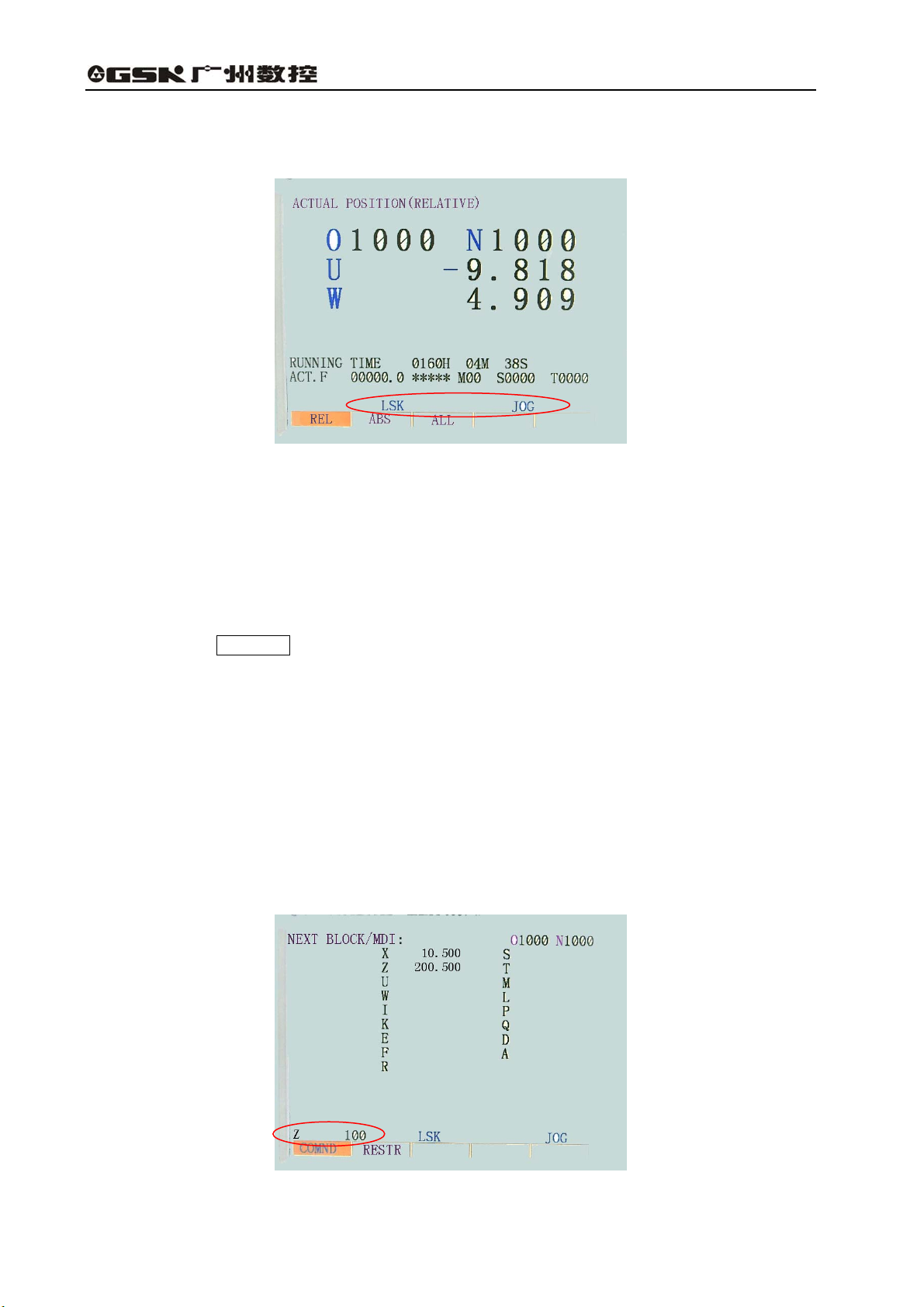
4.4.9 MDI operation (functional key COMMAND )
A block command to be executed may be input through MDI panel.
(1) Example: For X 10.5 Y200.5
(a) Select the MDI mode;
(b) Press the COMMAND key;
(c) Press the PAGE key. “NEXT BLOCK (MDI)” appears on the upper left of the screen.
34
Page 39

Volume Ⅱ Chapter 4 Operation
Fig. 4-48
(d) Press the X , 1 , 0 , • , 5 and the INPUT key in succession.
If the numeral entered before pressing the INPUT key is incorrect, press the
CANCEL key and enter the correct numeral again.
If an error is found after pressing the INPUT key, it is necessary to enter the numeral
again.
(e) Press the Z , 2 , 0 , 0 , • and 5 and the INPUT keys in succession.
If the typed numeral is found incorrect, proceed in the same way as inputting X.
Fig. 4-49
(f) Press the CYCLE START key on the control panel of the machine.
(2) Delete Z200.500 from X10.500 Z200.500 before pressing the CYCLE START key.
(a) Press the Z , CANCEL and INPUT key in succession.
(b) Press the CYCLE START key on the control panel.
(3) Delete modal data
Since modal G code and F, E and T data cannot be deleted, it is necessary to input correct data
for alteration.
4.4.10 MDI start and running
By pressing CYCLE START key, the commands by MDI is executed.
35
Page 40

GSK983T Turning CNC System User Manual
4.4.11 Reset
RESET key is usually used to cancel the alarm state.
By pressing this key, the NC turns into the following state:
Table 4-13
Before resetting After resetting
Move commands being executed
M,S,T codes being outputted
When a block is
read into the buffer
MDI mode The content in buffer is not eliminated.
Modes other
than above
The NC turns into reset state under any modes, but skip state in a mode other than MDI if
RESET key is pressed.
Slow down to stop and the remaining move is
cancelled.
Output sequence is terminated.
Refer to machine manual for actions at
machine side.
The content in buffer and BUF display are
both eliminated.
4.4.12 Setting and display of the tool offset, tool nose radius compenstation
(functional key offset )
4.4.12.1 Absolute input
(1) Press OFFSET key;
(2) Due to multiple pages to be displayed, PAGE keys are needed to select the page required;
st
1
page Offset 1~7
nd
page Offset 8~9 or 8~14(optional)
2
rd
3
page Offset 15~21(by selection)
th
page Offset 22~28(by selection)
4
th
page Offset 29~32 or (by selection)
5
36
st
Fig. 4-50 1
page of the offset values
Page 41

Volume Ⅱ Chapter 4 Operation
(3) Move the cursor to the No. of the offset to be altered
Method 1 Press ∧ , ∨ key, move the cursor sequently, and it changes to next
page if the cursor is over a page;
Method 2 Key in N , offset No., INPUT keys.
(4) Select a mode other than Edit
(5) Key in : X or Z or R or T offset value, INPUT
X Z : offset values of X, Z axes (absolute)
R : offset value of tool nose radius (absolute)
T : Assumed tool nose No.
If keying in Z 1 5 . 4 INPUT at an offset No. 4, it is shown as following
figure:
Fig. 4-51
Note1: The maximum offset value is restained by parameter No.338.
Note2: it can be keyed in when the figures at the right and bottom edge without blinking, and key in NO can
clear the blinking state.
37
Page 42

GSK983T Turning CNC System User Manual
4.4.12.2 Incremental input
By selection, it may choose the incremental offset input, so it can be done by U W keys.
X
Z
U
W
R
T
X
,
U
,
R
T
The input of R value by absolute or increment is defined by parameter #7.6 (IOF).
The incremental offset input is the increasement or decreasement of the offset.
(1) Incremental offset input
Now the tool nose R offset is 5.678, key in R 1 . 5 INPUT keys by
sequence, the offset turns to 7.178.
(2) When the absolute is needed in the incremental offset input:
Now the offset is 5.678, press R CANCEL INPUT keys by sequence, the offset turns to
0. Then press R 1 . 5 INPUT keys by sequence, the offset turns to 1.5.
Note1: When an offset is altered in Auto mode, the new one takes effect from next block or next T code
commanded is defined by parameter (TLCC) .
Note2: it can be keyed in when the figures at the right and bottom edge without blinking, and key in NO can
clear the blinking state.
Offset number Input
Z
:Offset in X or Z axis(abslute)
W
:Offset in X or Z axis(incremental)
:Tool nose R Offset (absolute or incremental)
:Assumed tool nose number
4.4.12.3 Setting of tool figure and wear offset
(1) Display of the tool wear offset
st
chapter of the OFFSET page it displays: (by pressing OFFSET key several
Fig. 4-52
times)
38
Under the 1
Page 43

Volume Ⅱ Chapter 4 Operation
(2) Display of the tool figure offset
Under the 3rd chapter of the OFFSET page it displays: (by pressing OFFSET key several
times)
Fig. 4-53
Setting:
(Ⅰ)It shows the page for tool figure offset or wear offset.
(Ⅱ)The setting is the same as that in section 5.12.1 and 5.12.2.
4.4.12.4 Offset of the workpiece coordinate system
It is the coordinate offset while there are deviation between the workpiece coordinate system
concerned in programming and the coordinate system commanded by G50 and automatic coordinate
system.
The offset value is set to the offset No.00, its setting steps are as the same as that of the tool
position offset.
Fig.4-54 Offset from 0′ to 0 set by offset No.00
XZ – 0 Coordinate system in programming
XZ – 0′ Current coordinate system
(Modifiable coordinate system by offsetting)
39
Page 44

GSK983T Turning CNC System User Manual
Fig. 4-55
As the above figure shows, the desired start point is X=120.0(diameter), Z=70.0 (offset value 0),
but the actual start point is X=121.0(diameter),Z=69.0), key in the offset value:
X=1.0 Z=-1.0
The desired coordinate system may be obtained.
Fig. 4-56
Also in above figure, if the start point locates at the tool nose tip, and it needs to be set at a point
of X=120.0(diameter),Z=70.0, while it actually locates at X=121.0 (diameter), Z=69.0, key in the
offset value of the workpiece coordinate system:
X=1.0 Z=-1.0
The desired coordinate system may be obtained.
The actual offset may be simply set by the direct offset input method for workpiece coordinate
system in section 5.12.5.
40
Page 45

Volume Ⅱ Chapter 4 Operation
Note 1: The offset of the workpiece coordinate system takes effect immediately after the offset value is set.
Note 2: After the offset value is set , then set coordinate system by G50, the offset doesn’t take effect.
e.g. Whatever the offset is, the current tool start point X=100.0 Z=80.0 is set for the new
coordinate system if the point G50 X=100.0 Z=80.0 is set.
Note 3: When performing the manual reference return after the offset value is set, once the automatic
coordinate system is set, the offset takes effect immediately, and the set coordinate system will be
offset right away.
Note 4: The offset in X axis by diameter or by radius is specified by the diameter or radius value in part
program.
4.4.12.5 Direct measured value input of workpiece coordinate system offsetting
If there are deviation between the coordinate system used in programming and the coordinate
system actually commanded by G50 and automatic coordinate system, offset the coordinate system
by direct measured values as follows:
Surface B
Origin of
programming
Surface A
Fig. 4-57
(a) Cut surface A with a reference tool in Manual mode.
(b) Press the POS RECORD key on the machine operation panel to make the tool detach the
part, and stop the spindle.
(c) Measure the distance β from programming origin to surface A in above figure.
(d) Press OFFSET. Press it again if the page of workpiece coordinate system offset has not been
selected.
(e) Key in N 1 0 0 INPUT , and the “N” keyed in will blink.
Fig. 4-58
41
Page 46

GSK983T Turning CNC System User Manual
(f) Key in Z , measured value β , INPUT , the offset value will be entered to Z of the
workpiece coordinate system offset.
(g) Cut surface B in Manual mode.
(h) Press the POS RECORD key on the machine operation panel to make the tool detach the
surface B, and stop the spindle.
(i) Measure the diameter α of the surface B.
(j) Key in X , measured value α, INPUT , the offset value will be entered to X of
theworkpiece coordinate system offset.
By the above operation, the offset from O′→ O will be automatically set to offset No.00, and the
set actual coordinate system will be consistent with the programming one.
Then the coordinate system X=0,Z=0 will be set if the reference tool offset is 0, i.e. the tool nose
is taken as the origin of the workpiece coordinate system of programming.
Note 1: When the offsets of X, Z in above figure is set for reference tool, under the active offset state(TXXXX
commanded) α,β settings are actually finished when finishing cutting surface A, B. When the start point
locates at the workpiece origin, the coordinate system X=0, Z=0 will be set.
Reference point
Fig. 4-59
Note 2:The value in X axis is usually measured by diameter.
4.4.12.6 Direct input of the tool offset
The offset by the deviation of the start point(reference tool nose or toolpost center) to the actual
tool nose point may be set by the following method:
While workpiece coordinate system is set:
Surface B
42
Surface A
Fig. 4-60
Page 47

Volume Ⅱ Chapter 4 Operation
(a) Select an actual tool to cut surface A in Manual mode.
(b) Press the POS RECORD key on the machine operation panel to make the tool
detach surface A, and stop the spindle.
(c) Measure the distance β from workpiece coordinate system origin to surface A.
(d) Press OFFSET key many times to switch to the page of the tool contour offset .
(e) Key in N , offset No.+No.100, INPUT to enter the direct input state.
So the desired page contains the offset No. is got with cursor pointing to this No., and the “N”
keyed in blinks.
Fig. 4-61
(f) Key in Z , measured value β, INPUT , so the Z offset is entered into this offset No.
(g) Cut surface B in Manual mode.
(h) Press the POS RECORD key on the machine operation panel to make the tool detach the
part, and stop the spindle.
(i) Measure the diameter α of the cylindrical surface B.
(j) Key in X , measured value α, INPUT , so the X offset calculated is entered into this offset
number.
Note1: The X value is usually measured by diameter.
Note2:when N or the figurs on left and bottom edge of the screen is binking, the operation of the clearing for
tool offset or input for increment is disabled, only after the N0 is inputed and canceling the N or the
blingking of the the figures, can the operation be enabled by X0 or Z0.
4.4.12.7 Offset input by counter (optional)
In the offset setting, press the INPUT key, the offset value will be set by relative coordinate U
(address X or U) or W (address Z or W) when address (X,Z,U or W)is keyed in without numerals.
Usage:
(a) Press the OFFSET key many times to select the OFFSET page of tool contour.
(b) Press ∧ , ∨ to select the page that contains the offset No. to be set. Or key in N ,
offset No. , INPUT .
(c) Move the reference tool to the start point by Manual mode.
(d) Reset the relative coordinates U, W in the page to 0 ( U SHIFT , W SHIFT )
43
Page 48

GSK983T Turning CNC System User Manual
Fig. 4-62
(e) Move the tool to be offset to the start point, the offset value will be shown at the Relative
position.
(f ) In tool contour offset page, by pressing U INPUT , W INPUT keys, the value at the
Relative position will be set for the tool offset.
4.4.13 Program display (functional key PROGRAM )
(1) In Edit mode:
Press the PROGRAM key, the current machining program is displayed.
Fig. 4-63
See Program number search in Section 4.4.14 for displaying a selected program.
Pressing the cursor ∧ , ∨ key to display the content of the program in sequence. By
pressing ∨ key, the page is displayed in forward direction. By ∧ key, in backward direction.
Note: If it is switched to Edit mode from other mode and the PROGRAM key is pressed, the content of
the program is displayed from the block being executed or executed. However, the beginning of the
program will be displayed when it is returned to program beginning (see 4.4.24.4).
(2) Automatic operation
Press the PROGRAM key, it displays the current block being executed.
44
Page 49

Volume Ⅱ Chapter 4 Operation
Fig. 4-64
Significance of the cursor (for auto running )
(a) When the cursor blinks, it indicates the block to be executed next time.
(b) When the cursor does not blink, it indicates the currently executing or executed block.
Note 1: Strictly speaking, when the buffer register is empty the cursor blinks neither in automatic
running nor in feed hold, which indicates the next block to be executed is going to be read into
the buffer register.
Note 2: When ∧ , ∨ key of the PAGE is pressed in Edit mode to move the cursor to Auto mode
and run, the block locating at the cursor in Edit mode is read into the buffer register.
4.4.14 Program number search (functional key PROGRAM )
When a lot of programs are stored in memory, each one can be searched out.
O1001 O3054 O1972
Searching a program number
(1) Method 1
(a) Select a mode (Edit or Auto).
(b) Press the PROGRAM key to switch to PROGRAM or PROGRAM CHECK page.
(c) Key in O , the program No. to be searched, ↓
The home page of the program is displayed after searching.
(2) Method 2
(a) Select the Auto mode.
(b) Press the PROGRAM key to switch to PROGRAM or PROGRAM CHECK page.
(c) Press O , V , Cancel, ↓ key in sequence. The next stored program is displayed.
(3) Method 3
(a) Select the Edit mode
(b) Press the PROGRAM key to switch to PROGRAM or PROGRAM CHECK page.
(c) Press O , ↓ key in sequence. The next stored program is displayed.
Note 1: It returns to the 1st program number as the display for all stored is over.
Note 2: The content in the buffer register is deleted when program number search starts.
45
Page 50

GSK983T Turning CNC System User Manual
4.4.15 Program input
A machining program can be directly stored into memory by the MDI keypads.
(a) Select the Edit mode (it is enabled when the program protection lock is open, it is disabled
when locked).
(b) Press the PROGRAM key to display the current program.
(c) Enter the program number to be stored by keying in O , program number , INSERT keys.
Fig. 4-65
(d) Key in a block according to the program
e.g. When keying in G50 X500.0 Z200.0 M12;
G 5 0 × 5 0 0 . 0
Z 2 0 0 . 0 M 1 2 EOB
Fig. 4-66
(e) If a keyed in character is incorrect, press the CANCEL key to delete the lastly keyed in
character. By pressing the CANCEL key continuously it deletes the keyed in characters
one by one from the last keyed in one. If the number of the characters of a block exceeds 32,
the block cannot be entered. Now it the block is needed to be divided for several segments.
(f) If the keyed in program is correct, press the INSERT key.
46
Page 51

Volume Ⅱ Chapter 4 Operation
Fig. 4-67
(g) Enter the following program by this means.
(h) For correcting a keyed in block, proceed as indicated in the section 5.30.
(i) For restart, move the cursor to the lastly keyed in character for continuous inputting. The
procedure is the same as the insertion operation.
(j) When all blocks are keyed in it finishes and at the end of the procedures, press the RESET
key if you want to return to the program beginning.
4.4.16 Deletion of a program (functional key PROGRAM )
Deleting a program stored in memory (Program lock ON for active; OFF for inactive):
(a) Select the Edit mode.
(b) Press the PROGRAM key.
(c) Press O , program number, and DELETE keys, the program with this number is deleted.
4.4.17 Deletion of all programs (functional key PROGRAM )
Deleting all programs stored in memory (Program lock ON for active; OFF for inactive):
(a) Select the Edit mode.
(b) Press the PROGRAM key to PROGRAM page.
(c) Press O , - , 9 , 9 , 9 , 9 and DELETE keys.
4.4.18 Sequence number search (functional key PROGRAM )
Sequence number search is usually used to search a sequence number in a program and start
or restart the program from the block whose sequence number is searched. Its skipping over blocks
exert no influence on the NC system. Namely when skipping over blocks, the coordinates of the
blocks skipped over, M, S, T or G codes do not change the coordinates and modal values of the NC.
When a user macro program is supplied, sequence number will not be displayed in searching.
Therefore, necessary M, S, T, G codes and coordinate system should be set for the blocks to be
started or restarted according to sequence number search. This block searched is usually a breaking
point in a process. If it needs to restart from the block searched in program, the present state of the
machine and NC system must be checked by specifying M, S, T, G codes and coordinate system etc.
with MDI.
47
Page 52

GSK983T Turning CNC System User Manual
r
m
Object numbe
Search the area from
beginning (only in
Program
number
selected
the program)
Fig. 4-68
(a) Select the Auto mode.
(b) Select the program number where the sequence number to be searched belongs to.
Fig. 4-69
If the program contains the sequence number searched, follow (c) operation. When the
sequence number to be searched does not exist in the block, however, the program with the
sequence number to be searched shall be selected by program search.
(c) Press the PROGRAM key.
(d) Key in N and the sequence number to be searched. Then press the cursor ∨ to find
the sequence number.
Note 1: Coordinates and modal data do not update during searching.
These data should be set through MDI after search.
Note 2: The following items are checked during searching:
Skipping over optional blocks
Alarm check (03, 04, 05, 10)
Note 3; M98P×××× (calling a subprogram) is not executed during sequence number search.
Therefore, when the sequence number in the subprogram called by the current selected program
is searched in Auto mode, No. 060 alarm will be given.
Main progra
Subprogram
Alarm occurs if searching N8888 in above example.
Fig. 4-70
48
Page 53

Volume Ⅱ Chapter 4 Operation
4.4.19 Restart of a program
When the machine restarts after the tool damage or stop of machining, the restart function starts
the machine from a block to be restarted according to the specified sequence number.
(1)The tool is damaged (P type)
(a) Press the FEED HOLD key, retract the tool and change for a new tool. Change the offset
when necessary.
(b) Set the PROG RESTART key on the operation panel to ON.
(c) Press the PROGRAM key to display the present program.
(d) Return to the start point of the program (Press the cursor ∧ key in Auto mode).
(e) Press the P , Sequence number and ∨ keys.
To search the block to be restarted, if the same sequence number appears for many times, (e.g.
when sequence number search calls a subprogram for many times), the higher four digits are
specified as the number of times of block appearance and the lower four digits as its sequence
number.
P 1 2 3 4 0 1 2 3 ∨
Number of times Sequence number
If the number of times is 1, the higher four digits can be omitted. The preceding zeroes can also
be omitted when the number of times is established.
(f)After search, LCD changes to display the page for program restart, and “RESTR” is displayed
at the botton and blinking.
Fig. 4-71
OBJECT It indicates the restarting position of machining.
DISTANCE TO GO It indicates the distance from the current tool position to the machining
restarting position.
M indicates the last commanded 35 M codes.
T indicates the last 2 commanded T codes.
S indicates the last commanded S code.
The first commanded code is indicated at the beginning of M and T.
(g) Set the PROG RESTART switch to OFF.
(h) Observe the page: Output by the MDI panel in MDI mode if the M, S, T codes to be output
exist. In this case, the M, S, T codes to be output no longer appear on the program restart page.
(I) Return to Auto mode for automatic running, check if the distance indicated by DISTANCE TO
49
Page 54

GSK983T Turning CNC System User Manual
GO is correct and if the tool contacts workpiece when the tool moves to the machining restarting
position. Press the CYCLE START key after manually moves the tool to a position that the
following tool move does not contact the workpiece. Now the tool moves to the restarting position by
dry run in the sequence of the Z, X axis, and restart machining.
(2) Restart machining (Q type) after the occurrence of the following conditions:
(a) Switch off the power.
(b) Press the EMERGENCY STOP button.
(c) The machine immediately stops due to storage type travel limit alarm.
(d) The coordinate system changes after the last automatic operation.
Example:
(Ⅰ) Specify G50 command through MDI.
(Ⅱ) Move the coordinate system.
(Ⅲ) Set the automatic coordinate system after reference point returning.
(Ⅳ) Reset the coordinates.
(a) After power on or the releases of emergency stop and travel limit alarm, the machine
performs the reference point return prior to the restart (see the notes below).
(b) The tool is manually moved to the programmed start point of machining and set modal data
and coordinate system which are identical with that of the the machine restart.
(c) If necessary, set or change the offset.
(d) Set the PROG RESTART key on the operation panel of the machine to ON.
(e) Display the program by pressing the PROGRAM key. Search the required program when
it is not available.
(f) Return to the the program start point. (Press the cursor ∧ key in Auto mode).
(g) Keying in the Q key and the sequence number, cursor ∨ key , the page switch to the
program restart automatically.
Search the sequence number that the block restarts.
When the same sequence number appears for many times during searching, the higher four
digits are specified as the times of sequence number appearances and the lower four digits as its
sequence number.
(h) Perform the same operations as (f),(g), (h) steps of P type.
(i) When the tool moves to the machining restarting position, check that the tool does not contact
workpiece. If necessary, manually move the tool to a position that does not contact the workpiece.
(j) Check if the distance indicated by the DISTANCE TO Go is adequate.
(k) Return to the Auto mode and press the CYCLE START key. Now the tool moves to the
restarting position by dry run in the sequence of the Z, X axis, and restart machining.
Note 1: In the following conditions, pressing the P key, the sequence number and the cursor ∨ key, it
does not restart the program.
(Ⅰ) After power on, no automatic operation is performed.
(Ⅱ) Automatic operation is not performed after the release of emergency stop or storage travel limit
alarm.
(Ⅲ) The automatic operation is not performed after the coordinate system is established, changed or
moved.
The (Ⅰ), (Ⅱ) above or 94, 96, 97 alarm reset causes P/S 97 alarm.
P/S 94 alarm is issued by the establishment of a coordinate system.
P/S 96 alarm is issued by the move of a coordinate system.
The block for the restartable machining is one of the many blocks. The block follows the block when
the coordinate system is last set or changed before the interruption of machining.
Note 2: In P or Q type, the tool moves to the machining restarting position by one axis each time. The stop of
50
Page 55

Volume Ⅱ Chapter 4 Operation
st
a single block is possible after the motion of the 1
operation can be inserted. The returned axes cannot move.
Note 3: When input signals, offsets and other conditions are different from the past in searching, the tool
cannot return to the machining starting position. i.e. the single block switch is set to ON or switch to
Auto/TAPE mode for continuous search operation.
Note 4: When feed hold is active during search or reset operation is performed in or after search, make sure
to carry out program restarting operation from the beginning. After the search, however, the reset
state in MDI mode is defined by parameter 006 CLER.
Note 5: Cycle start can be ignored provided that the program restart switch is set to ON.
Note 6: Always set the manual absolute switch to ON position for manual operation no matter it is before or
after machining.
When a program restarting operation instead of resetting is performed after manual operation or
when manual operation is performed along the axis that has not returned to the machining restarting
position, the motion concerned is assumed to be performed as the manual absolute switch is set to
ON position regardless the manual absolute switch is at ON or OFF position.
Note 7: In principle, the tool cannot return to the correct position in the following cases:
(a) When the manual absolute switch is set to OFF for manual operation.
(b) When the tool is moved in the lock state of the machine.
(c) When external mirror image function is used.
(d) When the coordinate system is not set at the beginning of incremental programming.
(e) When program mirror image function is used.
(f) When manual operation is inserted during the returning of an axis.
(g) When machine lock is disabled after the program restart is commanded in machine lock state.
(h) When program restart command is given during the execution of the cutting blocks with skip or
before the block with absolute command being executed.
(i) When the program restart is commanded in the blocks of the compound canned cycle.
(j) When coordinate system and offset are established after search. Nevertheless, in the condition of
(c) the P type return of the tool is available in the blocks following the block that has ON/OFF
switching. In this case, interruption in the mirror image remains the same. In addition the P type
return of the tool in the condition of (e) is also available.
Note 8: When the specified block only includes M98, M99, macro program calling command (M65, G66 and
G77) or macro program statement, or block not specified is searched, No.60 alarm will be given.
Note 9: When program restarting operation is commanded and G28 is detected without returning to the
reference point after power on, release of emergency stop or travel limit alarm (immediate stop), P/S
alarm (98) will be issued.
Note 10: After the search, P/S alarm (99) is given when a move command is executed through MDI
operations before axis motion.
Note 11: After the program restart is commanded, “RSTR” blinks at the bottom of the LCD screen before the
return of the last axis (Z).
Note that no alarm is given in above case!
axis. However, manual operation rather than MDI
4.4.20 Comparison and Stop function for sequence number
This function is used to stop machining after an command is executed to a preset sequence
number.
(a) Select the MDI mode.
(b) Press the SETTING key to display the setting page. (Move the cursor to the number
180 by pressing the ∨ key. The cursor can’t be moved at address N .
(c) Key in the command in the sequence of P , the sequence number to stop, and
INPUT .
(d) Select the Auto mode for machine automatic operation.
(e) Press the CYCLE START key. The machine stops after the data in the block whose
sequence number has been preset in step (c).
51
Page 56

GSK983T Turning CNC System User Manual
(f) The preset sequence number is cleared while the Comparison and Stop function is being
exectued.
(g) If the function is needed to execute once again, repeat the above steps from(a).
Note 1: Sequence number O cannot be used for comparison stop.
Note 2: The predetermined sequence number is cleared by resetting. Hence after the setting, automatic
running is performed in a state not reset.
4.4.21 Display of parameters (functional key PARAMETER )
Press the PARAMETER key to display the parameters, which are laid out in several pages.
Find the desired parameter by pressing the PAGE key (see Appendix 5 for the meanings of
parameters).
4.4.22 Program edit (functional key PROGRAM )
The programs stored in memory may be altered. The alteration is done by word unit.
(1) Select the Edit Mode.
(2) Press the PROGRAM key.
(3) Select the program No.. Proceed with (4) if the program has been selected; otherwise,
perform program number search.
(4) Search the word to be altered.
(a) By scanning.
(b) By word search.
(5) Alter, insert or delete the words.
Note 1: Word definition and edit unit
A word comprises an address and the numeral that follows. For user macro program, however, the
concept of word is indefinite. Hence the concept of “edit unit” is adopted. Edit unit serves as the
object of alteration and deletion in a single operation. Move the cursor to the edit unit beginning in a
single pass. For data insertion, the data is inserted behind the edit unit.
Definition of edit unit
(1)From one address to the next one;
(2)Address:character, IF, WHILE, GOTO, END, DO, =, ; (EOB)
According to the definition, a word is also an edit unit.
On the basis of the following explanations about edit, strictly speaking, word shall be called “edit
unit”.
Note 2: During program execution, machining is temporarily suspended by single block stop, feed hold and
other functions. Nevertheless, continuing to execute a program is not allowed after program
alteration, insertion and deletion; otherwise the program cannot be correctly executed. Program is
displayed on the LCD after subsequent machining.To alter stored data in Edit mode, they must be
altered in reset condition before program execution or when resetting operation is performed after
editing.
4.4.22.1 Word scanning
Scan a word each time
(1) Press the cursor ∨ key.
The cursor moves forward word by word on the screen. The cursor is displayed underneath the
address character of the selected word.
(2) Press the cursor ∧ key. The cursor moves reversely word by word on the screen. The
cursor is displayed underneath the address character of the selected word.
(3) Continuous search can be conducted by pressing down and holding the cursor ∨ or ∧
52
Page 57

Volume Ⅱ Chapter 4 Operation
key.
(4) The next page is displayed and search starts from the beginning of the page by pressing the
page ∨ key.
(5) The previous page is displayed and search starts from the beginning of the page by pressing
the page ∧ key.
(6) Displaying page by page is possible by pressing down and holding the cursor ∨ or ∧
key.
4.4.22.2 Word search
When searching a word, use this method.
Search a specified word from the present position forward.
Search direction
N1234×100.0 Z1250; S1234; N5678 M03
Present/scanned word The object of search S1234
(word displayed)
(1) Key in S , 1 , 2 , 3 and 4 with the keypad.
Note 1: The search for S1234 can not be done that it only enters S123 with the keypad.
Note 2: The search for S009 can not be performed as it only enters S9 with the keypad. S009 shall be
entered with the keypad for the search.
(2) Press ∨ key to start searching.
The cursor is displayed underneath S of S1234 after the search.
4.4.22.3 Address search
Search a specified address from the present position forward.
the search.
N1234×100.0 Z125.0; S1234; N5678 M03
Present/scanned word The object of search M03
(word displayed)
(1) Key in M .
(2) Search starts when the cursor ∨ is pressed. The cursor is displayed underneath M after
Note : either word search and address search do not start by pressing the cursor .
4.4.22.4 Methods for returning to the beginning of a program
01100 N0001×12.34; Z15.67; G01×12.5; M04
Beginning Present/scanned word
(word displayed)
53
Page 58

GSK983T Turning CNC System User Manual
(1) Method 1 A program is displayed from its beginning when the RESET key is pressed in
Edit mode.
(2) Method 2 Perform program number search.
(3) Method 3
(a) Set to Auto mode.
(b) Press PROGRAM key to enter into the program page.
(c) Press the cursor ∧ key to display the program from the beginning.
4.4.22.5 Word insertion (active when the program lock is ON)
To insert T105
N1234×100.0 Z125.0; S1234; N5678 M30;
Object of search
(1) Quickly search and scan the word preceding the position where a word is to be inserted.
(a) See 4.4.22.1 for scanning.
(b) See 4.4.22.2 for word search.
Positioning the cursor to Z1250.
(2) Key in the word to be inserted.
T 1 0 5 INSERT
Note 1: When what is inserted is not an address but a numeral, the inserted number is added to the
word(Edit unit) indicated by the cursor; in the above example, the insertion of 2.5 will create
Y12502.5 when the cursor is underneath Z in Z1250.
Note 2: A numeral can also be added to the behind of all addresses, e.g. EOB, IF, etc. When the cursor is
underneath “;”, the insertion of 23 will create “; 23”. However, it makes no sense in programming.
4.4.22.6 Word alteration (active when the program lock is ON)
(1) Search and scan the word to be altered.
(2) Key in the new word M , 1 and 5 and press the ALTER key.
N1234×100.0 Z125.0 T105; S1234
To be changed to M15
N1234×100.0 Z125.0 M15; S1234
Block altered
4.4.22.7 Insertion or alteration of words, blocks and strings
Words, blocks, character strings can be inserted (up to 32 characters).
In the foregoing example, to insert T105 M20, key in
T 1 0 5 M 2 0 INSERT key.
Likewise a word indicated by the cursor can be changed to words, blocks or strings, etc.
Note 1: When the cursor is underneath Z in Z125.0, by the insertion of 2.5 M20 it becomes Z125.02.5 M20.
Note 2: When the cursor is underneath T in Z125.0 T105, by the insertion of 2.5 M20 it becomes Z125.02.5
M20.
54
Page 59

Volume Ⅱ Chapter 4 Operation
4.4.22.8 Word deletion (active when the program lock is OFF)
The block after deletion
N1234 X100.0 Z125.0 T105; S1234;
To delete Z1250
(1) Search and scan the word to be deleted.
(2) Press the DELETE key.
N1234×100.0 T105; S1234;
4.4.22.9 The deletion till EOB(active when the program lock is ON)
Presently searched/scanned word(displayed)
underneath of the address character of the next word.
N1234×100.0 Z125.0 T105; M13; S1234;
Range of deletion
Press the EOB and DELETE keys to delete the part till EOB and the cursor moves to the
S1234
4.4.22.10 Deletion of blocks (active when the program lock is ON)
The range of deletion covers from the currently indicated word to the block whose sequence
number is specified.
1234 M10; M15 X10.0;…… T0122; N2233 S1200; N3344 Z10.0;
N
Range of deletion
(1) Key in the sequence number of the last block to be deleted start from the position of the
cursor. As follow:
N 2 2 3 3
(2) Press the DELETE key.
N3344 Z10.0;
4.4.22.11 Memory sorting
The frequent edit of part program sometimes prevents the memory from economic usage,
resulting in the failure to store the program data whose length is specified. Hence it is necessary to
regularly do memory sorting.
(1)In Edit mode.
(2)Press the PROGRAM to the page of program or program check.
(3)Press the CANCEL and SHIFT keys in sequence
After sorting, the admissible number of characters is indicated at the bottom of the screen.
55
Page 60

GSK983T Turning CNC System User Manual
Note 1: For one program, the memory stores it by the standard length. For many programs, some
storage areas are used to identify these programs.
Note 2: The storage areas to be altered or inserted exceeding the actual length are wasted in quick part
program edit. Memory sorting may eliminate these waste.
4.4.22.12 Display of all stored program numbers
Once the contents of the memory described in 5.22.11 are sorted, all stored program numbers
are displayed.
Fig. 4-72
4.4.22.13 Edit of user macro program
User macro program may be edited as the common program edited in Edit mode with the
program lock switch is released. The following points shall be observed:
(a) SHIFT key
Once the SHIFT key is pressed, the cursor changes from “—” to “∧”. Press the key with a
character in the lower right of it on the MDI panel in this state, this character in the lower right can be
entered.
After entering a character, the cursor restores to “—”. If the SHIFT key is pressed twice, the
cursor also restores to “—”.
(Example)
PROGRAM:
Cursor
56
Cursor for keyed in
Fig. 4-73
Page 61

Volume Ⅱ Chapter 4 Operation
(b) Deletion, insertion and alteration of a program
While editing an entered user macro program, the cursor moves at the following locations:
(Ⅰ) At an address
(Ⅱ) At the / of an optional block skipped over
(Ⅲ) At the left beginning # of a substitution statement
(Ⅳ) (,=, ;
(Ⅴ) At the initial character of IF, WHILE, GOTO, END, DO or SETVN
On the LCD screen, there is a character blank space before the characters above. Deletion,
alteration and insertion may be performed by a unit between the front and rear cursor positions.
(Example) Cursor position
001 X-#100 ;
N
#1=123 ;
002 / 2 X [12/#3] ;
N
03 X-SORT [#3/3*#4+1]] ;
N0
N004 X-#2 Z#1 ;
N
005 #5 = 1+2-#10 ;
IF [#1 NE 0] GOTO 10 ;
HILE [#2 LE 5] DO 1 ;
W
# [2000+#2] = #2*10 ;
#2 = #2+1 ;
ND 1 ;
E
Note 1: The cursor cannot be stopped inside ( ).
Control OUT/IN
(Example) ( _#1=100) ;
The cursor cannot stop here.
Note 2: The position of the cursor can change with the changed program.
(Example) X100 Z200;
If Z200 is changed into 100 with the ALTER key, it will become X
100100.
(c) Abbreviations of macro program words
To alter or insert a macro program word, the word can be abbreviated to its first two
characters. The underlined part can represent the word as an abbreviation. i.e. WH
ILE,GOTO,END,
R,AND,SIN,COS,TAN,AT AN,SORT,ABS,BCD,BIN,FIX,FUP,ROUND,SETVN
SO
(Example): When WH [TA[#1*AB[*2]]LERO[#3] ] is entered as data of keyboard entry, the actual
entry will be: WHILE [TAN [#1*ABS[#2] ]LEROUND[#3] ] .
4.4.23 Display of running time
Automatic running time can be accumulated and displayed in hour, minute and second
(increment of 2s) on the screen. Time is displayed as indicated in the figure below when the
SETTING key is pressed. Press the PAGE key for other pages.
57
Page 62

GSK983T Turning CNC System User Manual
Fig. 4-74
Note 1: The accumulated time includes automatic running time but not the stop times of feed hold and
single block.
Note 2: If the power supply is switched off after the stop of automatic operation, a time error up to 6
minutes may be caused after power on again.
Note 3: When necessary, time can be preset through setting operations. See section 4.4.8, the data
number is 57, 58, 59.
4.4.24 Menu switch function
It is possible to enable or disable the switch function of the CNC memory using the LCD instead
of the machine operation panel. With this function, the number of switches on the operation panel can
be reduced.
The signals that may be switched on or off through the LCD are as follows:
(1) SINGLE BLOCK
(2) MACHINE LOCK
(3) DRY RUN
(4) BLOCK SKIP1~9
(5) X MIRROR IMAGE,Z MIRROR IMAGE
(6) DISPLAY LOCK
(7) AUX FUNC LOCK
(8) MANUAL ABSOLUTE
Once the switch signal data set on the LCD is stored into magnetic memory, these switch data
remains unchanged even the power is cut off.
These signals are not completely determined by those displayed on the LCD.
These signals are deemed to be switched on no matter whether the machine panel signals or the
signals set on the LCD are switched on.
Therefore, these signals can be switched on or off through the LCD if they are cancelled through
the operation panel or disconnected with the signal cables.
Refer to machine manual for signals on/off by MDI/LCD switch.
Setting and display:
The LCD state of the above signals may be displayed through the following operations.
(a) Display
(Ⅰ) Select the setting chapter 3, for setting display, press the SETTING key and then press it
twice again.
(Ⅱ) Press the PAGE key to select the desired page from the two pages displayed.
58
Page 63

Volume Ⅱ Chapter 4 Operation
Page 1: displays the switches other than optional blocks skipping
Page 2: displays optional block skipping 1~9 switch.
(b) Setting
Proceed as follows after the above procedures:
(Ⅰ) Move the cursor to the item to be changed by pressing the cursor ∨ , ∧ key.
(Ⅱ) When the address P is pressed, enter 1 for switching on and 0 for switching off. Press
the keys in the sequence of P , 0 or 1 , INPUT.
Fig. 4-75
4.4.25 Graphic function
4.4.25.1 Function introduction
The actual processing may be checked by the tool path of machining shown on the LCD. And the
graphic scaling up or down may also be done on the LCD.
By parameter setting it may select the following 3 drawing coordinate system.
Fig. 4-76
AXIS PLAN SELECT=0 to select(0)
AXIS PLAN SELECT =1 to select(1)
AXIS PLAN SELECT=2 to select(2)
59
Page 64

GSK983T Turning CNC System User Manual
α
β
α
The maximum graphic dimensions (on LCD) are as follows:
Gc Graphic center
54mm 72mm
72mm 54mm
Fig. 4-77
The maximum graphic range shown in above figure covers 144mm horizontally, 108mm vertically.
If the drawing scope is over this range, the scale that ranges from 0.01 to 100.00 may be used.
Usually the scale is defined by following factors:
SCALE=smaller one of H, or V
SCALE H =
SCALE V =
length path programmed horizontal
length path programmed upright
: 144mm (by radius )
288mm (by diameter)
β: 108mm (by radius )
216mm (by diameter)
Note 1: Usually Z axis is specified by radius, X axis by radius/diameter via a parameter, and the scaling
is usually according to the screen center.
Program After scaling Gc: graphic
center
Gc
Programmed path
GO
+
Path after scaling
Fig. 4-78
When the tool path is out of the center, the tool path may exceed the drawing range. Then it may
use the following 4 parameters:
RANGE X (MAX):
RANGE X (MIN):
RANGE Z (MAX):
RANGE Z (MIN):
So the graphic center (GCX,GCZ) may be calculated by following formula:
GCX=[X(MAX)+X(MIN)]/2
GCZ=[Z(MAX)+Z(MIN)]/2
Note 2: Even X axis is specified by diameter in programming, X (MAX),or X (MIN) is specified by radius.
60
Page 65

Volume Ⅱ Chapter 4 Operation
The values are determined by input unit 0.001mm or 0.0001 inch. In addition, it turns into
0.0001mm, 0.00001inch if “insertion unit 1/10” is selected.
Once these parameters are set, they remain active till T key is pressed in Graphic page.
Even the workpiece coordinate origin is changed, the graphic origin and center is not changed on
screen. That is, workpiece coordinate origin always coincides with the graphic origin.
(Example)
Fig. 4-79
After G50 command is executed, the drawing path is shown as the divided line ( )
As for rapid moving, the tool path is indicated by a dot line( ), as for cutting moving,
the tool path is indicated by a continuous line ( )
4.4.25.2 Operations
(1) Graphic parameters setting
The parameters that can be set for graphics in any mode should be set in advance.
① Press the GRAPH soft key,the graphic parameters as following figure may be shown on LCD.
Fig. 4-80
② Press the ∨ or ∧ key, the cursor may be moved to the object position.
③ Set the graphics parameters by keying in P , numerals, INPUT keys.
④ Repeat operations to finish all the parameters.②③
(2) Graphic parameters description:
AXIS PLAN SELECT:set grahic p(XZ=0、left ZX=1 and right ZX=2)
61
Page 66

GSK983T Turning CNC System User Manual
Fig. 4-81
RANGE(MAX),(MIN): Set maximum or minimum range for tool path on graphic plane
X=0,0
Z=0,0
Setting range:
0~±99999999
1=0.001mm or 0.0001inch(usually)
1=0.0001mm or 0.00001inch(input unit /10)
Setting range:
1~100000
1=0.01 fold(usually)
LCD CENTER X: set graphic center coordinate in workpiece coordinate system
LCD CENTER Z: If MAX, MIN of RANGE are set,they are automatically set after the 1
graphic.
(3) Tool path description:
① In GRAPHIC PARAMETER page, press AUX soft key again, it displays as following:
st
Current position
(absolute)
Drawing status
S: ST… in drawing
T: TRM… drawing end
* … valid mark
Fig. 4-82
② Press T key, then press S key, the mark “*” moves to S: ST, so the LCD is ready for
drawing. And it will be cleared if there is a graphic.
③ Start auto run, and the tool path will be shown on the LCD.
④ Press T key, the drawing stops. Press S key, the previous graphics disappears and it
starts next drawing.
Note 1: Because the drawing is done according to the coordinates changed in auto running, the program
must be started in Auto mode. Please lock the machine if drawing is to be done alone.
62
Page 67

Volume Ⅱ Chapter 4 Operation
Prog
Note 2: Since the drawing can’t be made if feedrate is too high, reduce the rate by dry run or the like for
drawing.
(4) Example
Condition: by diameter
Input unit: 0.001mm
Drawing plane 1(AXES=1)
ram
Program start point
(130,150)
Fig. 4-83
(a) Drawing for the whole tool path:
If MAX,MIN values are set as following, the drawing center is (35, 75).
XMAX=70000, XMIN=0
ZMAX=150000, ZMIN=0
SCALE H=144/150=0.96
SCALE V=216/130=1.66
SCALE 0.96(96)
(b) Drawing in the shadow:
XMAX=30000,XMIN=0
ZMAX=90000,ZMIN=40000
SCALE H=144/50=2.28
SCALE V=216/60=3.6
SCALE 2.88(=288)
(c) To deviate the graphic, substitute the values of MAX and MIN with the same value
MAX+α, MIN+α
α<0, upward, deviate to the right
α>0, downward, deviate to the left
63
Page 68

GSK983T Turning CNC System User Manual
4.5 Display on Position Displayer (Optional)
The position displayer shows the current position.
There is an axes position reset key on position displayer, when this key is pressed, the
corresponding axis position is cleared and this point will be taken as the origin.
When a coordinate system (G50) is set by parameter (PPD), or by program, or by MDI panel, its
coordinates can be set into the position displayer.
Note 1: If the displayer lock switch is set to ON, the move in this state is equivalent to no moving in
position displayer. So there is a difference between the actual moving amount and the value
displayed.
Note 2: Position is displayed by inch unit when inputing by inch; and millimeter unit when inputting by
millimeter. Press RESET key to clear the displayer when switching between millimeter and inch
units. Either of the switching between millimeter and inch units does not change the data
displayed, but change the decimal point position.
Note 3: The displayer doesn’t show the mechanical compensation such as backlash compensation.
64
Page 69

Volume Ⅱ Appendix 1
Appendix 1 Codes for Programming
ISO code Code meaning ISO code Code meaning
0 Numeral 0 V Address V
1 Numeral 1 W Address W
2 Numeral 2 X Address X
3 Numeral 3 Y Address Y
4 Numeral 4 Z Address Z
5 Numeral 5
6 Numeral 6
7 Numeral 7
8 Numeral 8
9 Numeral 9
A Address A
B Address B
C Address C
D Address D
E Address E
F Address F
G Address G
H Address H
I Address I
J Address J SP Space
K Address K + Positive sign
L Address L - Negative sign
M Address M / Stop of optional block
N Address N · Period (decimal point)
O Address O # Hash sign
P Address P * asterisk
Q Address Q , Comma
R Address R ;
S Address S = Equal sign
T Address T [ Left square bracket
U Address U ] Right square bracket
Semicolon, end of block
(input by EOB)
65
Page 70

GSK983T Turning CNC System User Manual
Appendix 2 G Codes List
The following codes may be used directly in this CNC system, but some special G codes may be
used by parameters setting:
Standard
G code
*G00 *G00 *G00 positioning (rapid) B
*G01 *G01 *G01
G02 G02 G02 Arc interpolation CW B
G03 G03 G03
G04 G04 G04 Dwell B
G07 G07 G07 Sine control of feedrate O
G10 G10 G10
G20 G20 G70 Inch input system O
G21 G21 G71
G22 G22 G22 Storage travel limit ON O
G23 G23 G23
G27 G27 G27
G28 G28 G28 Return to reference point O
G29 G29 G29 return from reference point O
G30 G30 G30
G31 G31 G31
G32 G33 G33 Linear, taper thread cutting B
G34 G34 G34
G36 G36 G36
G37 G37 G37
*G40 *G40 *G40
G41 G41 G41
G42 G42 G42
G50 G92 G92
G65 G65 G65
G66 G66 G66 User macro mode call O
G67 G67 G67
G68 G68 G68 13 Double toolpost mirror ON O
Special G
code B
Special G
code C
Group
No.
01
00
06
04
00
01
00
07
00
12
Function
Linear interpolation (cutting
feed)
Basic/Optional
B
Arc interpolation CCW B
Offset setting O
Metric input system O
Storage travel limit OFF O
Reference point return
check
Return to the 2
nd
reference
point
O
O
Skip O
Variable lead thread cutting O
Automatic tool
compensation X
Automatic tool
compensation Z
Cancel tool nose R
compensation
Tool nose R compensation
–left
Tool nose R compensation
– right
Coordinate system setting,
spindle max. speed setting
O
O
O
O
O
B,O
User macro call O
User macro mode call
cancel
O
66
Page 71

Volume Ⅱ Appendix 2
G69 G69 G69 Double toolpost mirror OFF O
G70 G70 G72 Finishing cycle O
G71 G71 G73 Outer circle roughing cycle O
G72 G72 G74 End face roughing cycle O
G73 G73 G75 Closed loop cutting cycle O
G74 G74 G76
00
G75 G75 G77
G76 G76 G78
G90 G77 G20 Cutting cycle A O
G92 G78 G21 Threading cycle O
01
G94 G79 G24
G96 G96 G96
02
*G97 *G97 *G97
*G98 *G94 *G94 Feed per minute B
05
*G99 *G95 *G95
— *G90 *G90 Absolute command B
03
— *G91 *G91
B: basic function O: optional function
Note 1: Some G codes may be specified in the same block. When G codes belong to the same group are
specified in a block, the lastly specified G code will be active.
Note 2: The G codes of 01~13 group are modal, once a G code is specified, it remains active till another
one from the same group is specified.By parameter setting, it may restore to the initial G code
state when CNC is reset. The G codes marked with * are the initial state G codes. If there are 2 G
codes with * in a same group, it should be set by parameter for which one is the intial state G
code. But for G20 or G21, it is a state before power on.
Note 3: The G codes in group 00 are non-modal, which are only active in a specified block.
Note 4: A G code of each group is displayed.
Note 5: When a G code not listed in the above table is specified or an optional G code not defined by
control unit is specified, No.010 alarm will be given. (But no alarm by G60 and G61.)
End face grooving cycle
and peck drilling cycle
Grooving cycle and parting
cycle of outer circle
O
O
Threading cycle O
Cutting cycle B O
Constant surface speed
control
Constant surface speed
control cancel
O
O
Feed per rotation B
Incremental command B
67
Page 72

Appendix 3 Range of Command Values
Min. unit 0.001 mm 0.0001 mm 0.001 mm 0.0001 inch
Max. stroke (distance to
reference point)
Max. command value
Feed per
Cutting feedrate
(override 100% )
Cutting feedrate
1/10(by parameters)
Rapid rate (axes independent)
Upper limit of cutting feedrate
Manual rapid rate
FO
minute
Feed per
rotation
Feed per
minute
Feed per
rotation
Address
X, Z, U, W,
Metric input
Metric output
±99999.999 mm ±99999.999 mm ±3937.0078 inch ±9999.9999 inch
I, K
R
F
±99999.999 mm ±3937.0078 inch ±99999.999 mm ±9999.9999 inch
0~99999.999mm 0~3937.0078inch 0~99999.999mm 0~99999.999mm
1~15000 mm/min 0.01~600.00 inch/min 1~15000 inch/min 0.01~600.00 inch/min
0.01~500.00 mm/r 0.0001 ~50.0000 inch/r 0.01~500.00 mm/r 0.0001~50.000 inch/r
0.1~15000.0 mm/min 0.01~600.00 inch/min 0.1~15000.0 mm/min 0.01~600.00 inch
0.001~500.000 mm/r 0.0001~50.0000 inch/r 0.001~500.000 mm/r 0001~50.0000 inch/r
60 mm/min~15000 mm/min 60 mm/min~15000mm/min 6.0 inch/min~600.0 inch/min 6.0 inch/min~600.0 inch/min
6~15000 mm/min 6~15000 mm/min 0.6~600.0 inch/min 0.6~600.0 inch/min
Inch input
Metric output
Metric input
Inch output
Inch input
Inch output
Jog feedrate
Thead lead
Thead lead(feedrate
68
F code F
E code F
F code F
1~2000 mm/min
0.001~500.000 mm/r
0001~500.000 mm 0.000001~9.999999 inch 0.0001~500.0000 mm 000001~9999999 inch
0.001~500-000 mm/r 0.0001~50.0000 inch/r 0.001~500.000 mm/r 0.0001 ~50.0000 inch/r
0.04 -78.7 inch/min
0.0001 -50.0000 inch
5~1016 mm/min 0.02~40 inch/min
0.01~500.00 mm 0.0001~50.0000 inch
Page 73

1/10 by parameter)
Maximum spindle speed 5000 r/min 5000 r/min 5000 r/min 5000 r/min
Coordinates of 2nd reference
point (distance to reference
point )
Tool offset value
Minimum value of incremental
feed
Backlash compensation
Setting range of storage or travel
limit (distance to reference point )
Dwell
Program No.
Sequence No. N
Preparatory function G
Spindle function S
Tool function T
Miscellaneous function M
Sequence No. specification P,Q
Repetitions L
Parameter
E code E
OFX, OFZ,
OFR
0.001 mm 0.0001 inch 0.001 mm 0.0001 inch
±99999.9 mm ±99999.999 mm ±3937.0078 inch ±9999.9999 inch
X, U,
P
: (ISO)
O (EIA)
Angle A Specified value
Cut depth D,I,K Same as coordinate word
Times D
0.00001~9999999 mm 0.000001~9.999999 inch 0.00001~99.99999 mm 0.000001 ~9.999999 inch
0~±99999.999 mm 0~±99999.99 mm 0~±3937.0078 inch 0~±9999.9999 inch
0~±999.999 mm 0~±99.9999 inch 0~±999.999 mm 0~±99.9999 inch
0~0.255 mm 0~0.255 mm 0~0.025 inch 0~0.0255 inch
0 ms~99999999ms 0 ~99999.999 s 0 ~99999.999 s 0 ~99999.999 s
0 ms~99999999ms 0m s~99999999ms 0 ms~99999999ms 0 ms~99999999ms
1~9999 1~9999 1~9999 1~9999
1~9999 1~9999 1~9999 1~9999
0~99 0~99 0~99 0~99
0~9999 0~9999 0~9999 0~9999
0~9932 0~9932 0~9932 0~9932
0~99 0~99 0~99 0~99
1~9999 0~9999 0~9999 0~9999
1~9999 0~9999 0~9999 0~9999
1~9999 1~9999 1~9999 1~9999
69
Page 74

GSK983T Turning CNC System User Manual
T
Δ
Appendix 4 Calculation Chart
D4.1 Incorrect thread length
In automatic acceleration and deceleration, thread cutting, it may result in the incorrect δ1,δ2
lead as Fig.4.1, so δ1,δ2 allowance should be given in programming.
Fig. A-1 Incorrect thread parts
(1) δ2 is defined by thread cutting speed V(mm/s)and servo time constant T1.
δ2=T1·V (mm)……………………………………………(A-1)
Unit: T1: s, V: mm/s
V is defined by thread lead L and spindle speed R.
1
V=
·R(r/min)·L(mm)
60
O The servo time constant T1(s)is usually calculated by T1=0.033.
(2) δ1 definition
δ1 is defined by thread cutting speed V and servo time constant T1 and thread precision
a.
δ1={t-T1+T1exp(-
a = exp (-
t
t
)} V……………………………………(A-2)
1
) ………………………………………………(A-3)
1T
Lead error ΔL is allowed when the lead is less than the specified lead L in the beginning
of the threading cutting, so
L
a =
……………………………………………………(A-4)
L
If a is confirmed, the time t for precision is decided by formula (3), put t value into (2) to
get δ1. And the V,T1,T2 are decided by the same method as that of δ2.
Because δ1 is hard to get by calculation, it may be got by the following figure, see the
explanation.
70
Page 75

Volume Ⅱ Appendix 4
⋅
δ1(V=10mm/s)
V=20mm/s Servo time constant
V=40mm/s T1
(2) T2
(3) (1)
O
L
L
Fig. A-2
First get the thread precision a at (1) according to the thread grade and lead, then get δ1 for
V=100mm/s at (2) by the acceleration and deceleration time constants in machining. Thus δ1 at other
velocity can be got according to the thread cutting feedrate at (3).
D4.2 Simple formula for incorrect thread length
Fig. A-3
RL
(1) δ2=
L; thread lead (mm) R; spindle speed (r/min)
(2) 1=
=δ2·(-1-Lna)
As *Servo time constant T=0.033
*1800
RL ⋅
·(-1-Lna)
*1800
(mm)
71
Page 76

GSK983T Turning CNC System User Manual
Fig. A-4 Calculation chart for approaching distance δ1
a is allowable thread error, the calculation for “-1-Lna” is as following:
Table A-1
a
0.0005 4.298
0.01 3.605
0.015 3.200
0.02 2.912
-1-Lna
(Example) As R=350rpm
L=1mm
a =0.01
δ
δ
=
2
1=δ2
1350 ×
=0.194mm
1800
×3.605=0.701mm
72
Page 77

Volume Ⅱ Appendix 4
(
r
D4.3 Radial error for arc cutting
There is an error between the output shaft and input shaft due to the motor lag when using DC
servo motor. In linear interpolation, no error occur in the commanded linear path by the tool, but in
circular interpolation, especially in high speed arc cutting, there is a radial error. This error may be
obtained by the following procedures:
Programmed path
Actual path
Fig. A-5
r△ : max. radius error (mm)
V: feedrate (mm)/s
r: arc radius
T1: exponential acceleration and deceleration time constant in cutting (s) (T1=0)
T2: DC motor time constant (s)
Note: The exponential acceleration and deceleration time constant in 6T is always 0.
r△ =
1
2
1
2
V
2
2
………………………………………(A-10)
)
•+
TT
2
The part radius r(mm) and allowable error r△ (mm)are given in actual machining, so the
allowable velocity V(mm/s)may be got by formula (A-10).
The acceleration and deceleration time constant in cutting varies with the machine tool, please
refer to the manual by the machine builder.
-
The time constant of DC servo motor is calculated by formula T
=33×10
2
3
(s)
73
Page 78

GSK983T Turning CNC System User Manual
Appendix 5 Parameters
When the CNC is connected to a servo motor or a machine, parameters should be set to
maximize the performance of the machine and the servo motor. Since parameters are involved with
machine types, please refer to the parameter list provided by the machine builder.
E5.1 Display of Parameters
Press the PARAMETER key on the NC panel, the parameters will be displayed on LCD.
Change the page by 2 methods:
Method 1
Press the PAGE ∧ key, it pages forward.
Press the PAGE ∨ key, it pages backward.
Method 2
Press the address N key, input the parameter No. to be searched by numeral keys,
then press INPUT key, the relevant parameter will be shown on LCD.
E5.2 Setting of Parameters
(a) Set the parameter switch on the CPU board to ON, and the alarm No.100 will be shown
on the LCD.
(b) Set the mode switch on the operation panel to MDI, or set the CNC to emergency state.
(c) See E5.1 Display of Parameters.
(d) Press cursor key; or press N key, then press the corresponding numeral keys in
sequence, lastly press INPUT key to select a parameter No.
(e) Press P key, then input the data, and this data will be shown on the bottom of the
page.
(f) In the event of error during keying in, press the CANCEL key.
(g) Press INPUT key to finish the data input. Make sure the setting is correct.
(h) After the setting of all parameters is finished, Set the parameter switch on the CPU board
to OFF. Cancel the emergency if CNC system is in emergency state.
(i) Press the RESET key to cancel the alarm state (No. 100).
(j) Cut off the system power once if No.000 alarm is shown.
E5.3 Parameter Table
Table A-2 Parameter No. Table
Parameter
No.
0000~0004
0005~0010
0012 Reference point return modes or directions
0013 Gear ratio of spindle to position encoder,
Fixed parameters
For various parameters
Contents
74
Page 79

Volume Ⅱ Appendix 5
0014~0015
DMR referring counter capacity
0018 Frequency of backlash compensation, input unit 1/10
0019 Time intervals of MF, SF, TF and FIN
0020 Validity of reference point return function
0024~0026
0027~0028
0031~0032
0035~0036
For various parameters
CMR
VLOC min. clamping value
non-buffer M code
0037 Spindle motor speed at spindle gear shift
0038 Spindle speed at spindle exact stop
0040
0041~0056
0057~0059
External tool compensation II—allowable value of B function limit check
External tool nose compensation II—data multiplier of B function outer diameter
measure
Machining time
0062 Signal counter of spindle velocity in-position
0064 Chamfering width in threading
0065 Retraction amount in G74, G75
0066 Finishing allowance in G76
0067 Retraction amount in G71, G72
0068 Min. cut depth in threading G76
0069 Minute move neglection of an acute angle near 90º in tool compensation
0070~0071
0074~0075
0078~0079
0082~0083
0086~0087
In-position width
Position offset limit at stopping
Position offset limit at moving
Grid offset
Gain override of servo loop
0090 Gain of servo loop
0091 JOG feedrate
0092~0093
Rapid traverse rate
0096~0097 Time constant of linear acceleration and deceleration(for rapid)
0100~0101
Time constant of JOG feed
0104 Time constant of X axis acceleration and deceleration in threading
0105 Time constant of acceleration and deceleration in cut feeding
0106
Upper limit of cut feedrate
0107 Lower limit of X axis acceleration and deceleration in threading
0108 Lower limit of acceleration and deceleration in cut feeding
0109~0110
JOG feedrate lower limit of in acceleration and deceleration
0113 The lowest rate (F0) of rapid traverse
0114 Low rate of returning to the reference point
0115~0116
Backlash compensation
0119 Spindle deviation compensation( S analog output )
0120~0123 Spindle speeds for gear 1~4 as spindle speed command is 10V
0124~0125
Offset compensation
75
Page 80

GSK983T Turning CNC System User Manual
0132 Spindle min. speed (G96) in constant surface speed control
0133 Measuring speed in automatic compensation
0140 Gain adjustment of spindle speed (S4 code analog output )
0141~0142
0143~0158
0159~0160
0163~0164
0165~0166
0300~0304
0305~0308
0310~0313
Presetting of operation time
Storage type travel limit setting
2nd reference point
r values of X, Z axes in automatic compensation
ε values of X, Z axes in automatic compensation
Fixed parameters
For various parameters
Baudrate of I/O device
0316 Parameters related with resolver/inductosyn
0317 Code to “#”sign (user macro program)
0319 Parameters related with user macro program
0320~0322
0323~0332
Macro program called by M codes
Macro program called by G codes
0340 Input device selection
0341 Output device selection
0342
Cutting speed of skipping
0343~0346 Spindle low speeds to Gear 1~4 in constant surface speed control
0358
0375~0376
0379~0380
0388
Max.input value of incremental wear offset
Automatic coordinate system setting value by metric input
Automatic coordinate system setting value by inch input
Max.value of wear offset
Table A-3 Parameter function table
Function
Parameter
No.
Content
005 Servo disable signal active or inactive
·Auto drift compensation active or inactive
·In-position check executed or not
Check override setting (DMR)
If alarm issued as VRDY signal is connected to servo before PRDY
output
Command override setting (CMR)
Clamping setting of feed command
In-position width
Position offset limit at stopping
Position offset limit at moving
Grid offset
Gain override of servo loop
Servo
006
014~015
026
027~028
031~032
070~071
074~075
078~079
082~083
086~087
090 Gain of servo loop
76
Page 81

Volume Ⅱ Appendix 5
Spindle
function
124~125
128~129
Drift compensation of X, Z axes
Servo phase shift
316 CDSCG Feedback frequency check executed or not
316
DSCG Resolver, inductosyn, pulse encoder for position detection
system setting
005 S4 code output and S code (BCD) output
009 S4 code output voltage sign(analog)
009 Spindle override function setting(SOV)
010
Spindle stop signal selection by normal-open or
normal-close(*SSTP)
037 Spindle motor speed at spindle gear shift
038 Spindle speed at spindle exact stop
062 Signal counter of spindle velocity in-position
119 Spindle speed deviation compensation( S4 code analog output A/B)
120~123
Spindle max. speeds for gear 1~4 as spindle command voltage is
10V
132 Spindle min. speed in constant surface speed control
134 Max. spindle speed allowable
140 Gain adjustment of S4 code analog output
307
S4 code binary 12 bits output / analog output low speed clamping
Setting for all axes or single axis active
0343~
0346
Reference point return
010
012 Reference point return modes or directions
function
014~015
020 Validity of reference point return function
082~083
114 Low rate setting of returning to the reference point
159~160
Tool compensation
040~056
163~164
165~166
Spindle low speeds to Gear 1~4 in constant surface speed control
Deceleration signal 0 or 1 setting in reference point return
(*DECX, *DECZ)
Axes referring counter capacities
Axes grid offset setting
nd
Distance beween axes from 2
reference point to 1st reference
point
007 Offset setting by incremental or absolute input
008 Offset setting by radius or diameter
010 If data setting allowable as machine lock is OFF.
040
External tool compensation—allowable value of B function limit
check(disabled)
External tool compensation—data multiplier of B function outer
diameter measure (disabled)
069 Minute move neglection in tool radius compensation
133 Speed measuring setting in automatic compensation
r value setting of X, Z axes in automatic compensation
ε value setting of X, Z axes in automatic compensation
77
Page 82

GSK983T Turning CNC System User Manual
0358
compensati
Backlash
on
Canned cycle
Macro command function
0388
012
018 Backlash compensation pulse frequency(256KHz)
115~116
008 Dry run validity setting in threading
009 Canned cycle setting for blocks without move command
064 Chamfering width setting in threading (G92, G76)
065 Retraction amount in G74, G75
066 Finishing allowance in G76
067 Retraction amount in G71, G72
068 Min. cut depth in threading G76
307 Finishing setting in the last profile cutting in G71, G72
025 Macro program interruption parameter
053 M codes for macro program interruption active
054 M codes for macro program interruption inactive
306 Setting of macro program called by T code
308 Setting of DI, DO read and write by macro program variables
314
317 Used for storing code of “#”sign by macro program
318 Used for parameters setting of macro program
319 Used for parameters setting of macro program
Max.input value of incremental wear offset
Max.value of wear offset
Initial backlash direction after power on
Backlash compensations of X, Z axes
Setting of macro program interruption executed in the middle or at
the end of the block
320~322
323~332
3 kinds of M codes setting for macro program call
10 kinds of T codes setting for macro program call
E5.4 Cautions for parameters usage
1) The parameters №0000-0004 and №0300-0304 differs with machine tools, please see the
additional parameter list for NC.
2) Please set to “0” for the parameters not listed in above table.
3) For the parameters by the format
and , they are set by binary system (1 or 0).]
4) “-” is unallowed for the parameter that has no sign.
5) The disabled parameter should be set to “0”.
6) It may be set to “0” for the parameter that has not been used with a specified setting range.
Those by the format are set by decimal system.
78
Page 83

Volume Ⅱ Appendix 5
E5.5 Description of parameters
Parameter
No.
Bit 7 Bit 6 Bit 5 Bit 4 Bit 3 Bit 2 Bit 1 Bit 0
0005 ORWD EIT EENB SCD FMIC MDL MIC SCW
Description
Set to 1 Set to 0
ORWD Unused
EIT Interlock signal active Interlock signal inactive
EENB Servo OFF signal active Servo OFF signal inactive
SCD
Even S4 code (analog output) or S4
code (binary 12 bits output)(optional)
is selected, S4 code (analog) or S4
code (binary 12 bits) command are
If S (analog output) or S4 code (binary 12
bits output)(optional) is selected, the S4
code codes are output, or else S code
(BCD) is output.
not transmitted, but S code (BCD) is
output.
FMIC Feedrate unit is 1/10 for metric input. Feedrate unit is not 1/10 for metric input.
MDL
MIC
SCW
Parameter
No.
Min. unit displayed by position
displayer is 0.01mm for metric input,
0.0001inch for inch input.
Min. set unit is 0.01mm for metric
input, 0.0001inch for inch input.
Min. move unit is 0.0001inch(inch
system).
Bit 7 Bit 6 Bit 5 Bit 4 Bit 3 Bit 2 Bit 1 Bit 0
Min. unit displayed by position displayer
is 0.001mm for metric input, 0.0001inch
for inch input.
Min. set unit is 0.001mm for metric input,
0.0001inch for inch input.
Min. move unit is 0.001mm(metric
system).
0006 ADFT EOM CINP DCS CLER TVC PPD RDRN
Description
Set to 1 Set to 0
ADFT
EOM
Perform automatic drift
compensation
When M30 is commanded, it is
transmitted to machine side and FIN
signal is feedback, it start from the
st
1
program block for continuous
execution. Or external reset but FIN
Not perform automatic drift compensation
It does not return to the program beginning
if M30 is commanded and transmitted to
machine side without reset and rewinding
signals (in storage mode).
signal is sent back from the machine
side, it returns to the program
beginning for resetting(in Auto
mode).
79
Page 84

GSK983T Turning CNC System User Manual
CINP
Between two non-cutting blocks, or
error detection is active, next block
is not executed till the mechanical
position coincides with the
commanded position as the
Between two non-cutting blocks, or error
detection is active, next block is executed
as soon as the specified speed slows
down to 0.
specified speed slows down to
0.(This is called in-position
detection.)
DCS
CLER
TVC
PPD
It starts by CYCLE START key
on the panel at NC side without
passing machine side. (only in MDI
mode)
Clear the NC by RESET key,
external reset signal, reset and
rewind signals.(see appendix 7)
Not perform TV check in control
output part (annotation).
The relative coordinate system
position display unit may be preset
The NC starts by CYCLE START key
on the panel when it receives the start
signal feedback from the machine side.
Reset the NC by RESET key, external
reset signal, reset and rewind signals. (see
appendix 7)
Perform TV check in control output part
(annotation).
The relative coordinate system display unit
may not be preset by G50(G92) command.
by G50(G92) command.
RDRN Dry run is active in rapid traverse. Dry run is inactive in rapid traverse.
Parameter
No.
Bit 7 Bit 6 Bit 5 Bit 4 Bit 3 Bit 2 Bit 1 Bit 0
0007 ICR IOF GSP SCTO G90 G98 G00
Description
Set to 1 Set to 0
ICR
EOB code is punched out by LF as
ISO code is punched out.
EOB code is punched out by LF CR CR as
ISO code is punched out.
The offset value input is taken as an
IOF
incremental one if incremental offset
is selected.(just for tool nose R
The offset value input is taken as an
absolute one.(just for tool nose R offset)
offset)
GSP Use special G code B. Use standard G code.
SCTO
Perform the speed in-position check
when it is from rapid traverse to
Not detect speed in-position signal.
cutting feed commanded by S code.
G90
G98
The initial state is G90 when power
on or clearing.(special G code)
It becomes G98 state when power
on or clearing(G94 for special G
The initial state is G91 when power on or
clearing.
It becomes G99 state when power on or
clearing(G95 for special G code B/C)
code B/C)
G00
It becomes G00 state when power
on or clearing.
It becomes G01 state when power on or
clearing.
80
Page 85

Volume Ⅱ Appendix 5
Parameter
No.
0008 ORC RWL TLCC T2D TOC NMTN TDRN
Set to 1 Set to 0
ORC Offset commanded by radius. Offset commanded by diameter.
RWL
TLCC
T2D
TOC Offset cancelled in resetting Offset not cancelled in resetting
NMTN
TDRN Dry run is active as for threading. Dry run is inactive as for threading.
Parameter
No.
Bit 7 Bit 6 Bit 5 Bit 4 Bit 3 Bit 2 Bit 1 Bit 0
Description
Forbidden area for outside of storage travel
limit 3.
New offset is active from next block if offset
is changed.
The lower 2 digits is for offset in T code(2+2
digits)
M,S,T but move commands are performed
as STLK signal is connected.( (STLK:
interlock signal)
Forbidden area for inside of storage travel limit 3.
New offset is active from next T code if offset is
changed.
The lower 1 digit is for offset in T code(1+1 digits)
M, S, T and move commands are not performed
as STLK signal is connected.
Bit 7 Bit 6 Bit 5 Bit 4 Bit 3 Bit 2 Bit 1 Bit 0
0009 TCW CWM SOV SSCR MOR SOVC REDT ISOT
Description
Set to 1 Set to 0
TCW
CWM
TCW CWM Symbol
Symbol of S4 code analog output
0 0
0 1
1 0
1 1
M03, M04 are both
positive.
M03, M04 are both
negative.
M03 is positive,
M04 is negative.
M03 is negative,
M04 is positive.
SOV Spindle override active Spindle override inactive
SSCR
MOR
SOVC
The peripheral speed in rapid block
is calculated by the X axis end point
coordinate in constant surface
control mode.
In a single canned cycle, the cycle is
executed in blocks with no move
commanded.
The spindle override is clamped at
100% in thread cutting
(G32,G76,G92).
The peripheral speeds are calculated by
the X axis current coordinates for rapid
traverse and cutting in constant surface
control mode.
In a single canned cycle, the cycle is not
executed in blocks with no move
commanded.
The spindle override is not clamped at
100% even in threading.(speed override
active)
81
Page 86

GSK983T Turning CNC System User Manual
In Edit mode, it may also store the
REDT
part program into the memory by
CYCLE START key.
With storage travel limit selection
ISOT
the manual rapid traverse is active
even reference return is not
performed.
Parameter
No.
0010 DGNE SETE DECI SSPB NPRD PROD CTHD
Set to 1 Set to 0
DGNE Data output active in diagnosis Data output inactive in diagnosis
SETE Input is allowed as lock key is ON. Input is unallowed as lock key is ON.
DECI
SSPB Spindle stops if *SSTP signal is “0”. Spindle stops if *SSTP signal is “1”. (standard 0)
NPRD Not use decimal point input and display Use decimal point input and display
PROD
CTHD For continuous thread cutting(disabled) Continuous thread cutting is disabled.
Parameter
No.
Bit 7 Bit 6 Bit 5 Bit 4 Bit 3 Bit 2 Bit 1 Bit 0
Description
Deceleration is active if *DECX,*DECZ is
“1”in reference return.
It displays the programming position as
current value is shown.
Bit 7 Bit 6 Bit 5 Bit 4 Bit 3 Bit 2 Bit 1 Bit 0
The part program can’ be stored into the
memory by CYCLE START key.
With storage travel limit selection the
manual rapid traverse is active only
reference return is performed.
Deceleration is active if *DECX,*DECZ is “0”in
reference return.
It displays the actual position involving the tool
compensation, tool nose compensation.
0012 ZGMZ ZGMX ZMZ ZMX
Description
Set to 1 Set to 0
ZGMZ
ZGMX
Reference return in Z axis by
magnet switch
Reference return in X axis by
magnet switch
The backlash initial direction is
ZMZ
negative for Z axis reference return
direction and power on.
The backlash initial direction is
ZMX
negative for X axis reference return
direction and power on.
Note 1: For the axis with reference return, the return direction is the same as the backlash intial
direction at power on. But for the axis with no reference return, this parameter only involves
the backlash intial direction.
Note 2: Backlash compensation is performed after power on when moving in the direction set by
this parameter.
Reference return in Z axis by grid
switch
Reference return in X axis by grid
switch
The backlash initial direction is positive
for Z axis reference return direction and
power on.
The backlash initial direction is positive
for X axis reference return direction and
power on.
82
Page 87

Volume Ⅱ Appendix 5
Parameter
Parameter
No.
0013 PSG2 PSG1 RVZRN
Set to 1 Set to 0
PSG2
PSG1
RVZRN
No.
0014
0015
Bit 7 Bit 6 Bit 5 Bit 4 Bit 3 Bit 2 Bit 1 Bit 0
Description
Gear ratio of spindle to position encoder
Override ×1 ×2 ×3 ×4
PSG2 0 0 1 1
PSG1 0 1 0 1
Reference return is disabled in
the reverse direction of the
returning in manual reference
return.
Bit 7 Bit 6 Bit 5 Bit 4 Bit 3 Bit 2 Bit 1 Bit 0
DMRX GRDX
DMRZ GRDZ
Override =
speed Spindle
speed encoder Position
Vb Reference return active in reverse
direction
Description
Set to 1 Set to 0
Detection overrides for X, Z axes
Override
Pulse encoder
DMRX
DMRZ
Setting code
0 0 0 1/2
0 0 1 1
0 1 0 1
0 1 1 2
1 0 0 3/2
1 0 1 3
1 1 0 2
1 1 1 4
83
Page 88

GSK983T Turning CNC System User Manual
Reference counter capacities for X, Z axes
Reference counter capacities=Detection override x2000 (for 2000PPr pulse
encoder)
= Detection override x2500 (for 2500PPr pulse
encoder)
Setting code Capacity for a cycle
0 0 0 1 2000
GRDX
GRDZ
0 0 1 0 3000
0 0 1 1 4000
0 1 0 0 5000
0 1 0 1 6000
0 1 1 1 8000
1 0 0 1 10000
Note: If a value not listed in above table is set, the capacity is set to 8000.
Note: DMR and GRD are set by binary system.
Parameter
No.
Bit 7 Bit 6 Bit 5 Bit 4 Bit 3 Bit 2 Bit 1 Bit 0
0018 DIC CPF2 CPF1
Set to 1 Set to 0
DIC Input unit is 1/10. Input unit is not 1/10.
Backlash compensation pulse frequency (for all axes) should be set to 256
KHZ.
CPF2
CPF1
Frequency
KHZ
32 64 128 256
CPF2 0 0 1 1
CPF1 0 1 0 1
Description
84
Page 89

Volume Ⅱ Appendix 5
Parameter
No.
0019 TMF TFIN
Set to 1 Set to 0
TMF
TFIN Duration of FIN signal receive width 16 ms ~256ms. (16ms interval)
Parameter
No.
Bit 7 Bit 6 Bit 5 Bit 4 Bit 3 Bit 2 Bit 1 Bit 0
Description
Duration from M,S,T code transmitting to MF,SF,TF code transmitting
16~128ms.(16ms interval)
M code
It is ignored for X<TFIN
TMF or TFIN=16×(N+1)ms (N=1-15)
TMF TFIN Setting
16 ms 16 ms above 0 0 0 0
32 ms 32 ms above 0 0 0 1
48 ms 48 ms above 0 0 1 0
64 ms 64 ms above 0 0 1 1
80 ms 80 ms above 0 1 0 0
96 ms 96 ms above 0 1 0 1
112 ms 112 ms above 0 1 1 0
128 ms 128 ms above 0 1 1 1
144 ms 144 ms above 1 0 0 0
160 ms 160 ms above 1 0 0 1
176 ms 176 ms above 1 0 1 0
192 ms 192 ms above 1 0 1 1
208 ms 208 ms above 1 1 0 0
224 ms 224 ms above 1 1 0 1
240 ms 240 ms above 1 1 1 0
256 ms 256 ms above 1 1 1 1
Bit 7 Bit 6 Bit 5 Bit 4 Bit 3 Bit 2 Bit 1 Bit 0
0020 CLSI ZTNZ ZTNX
Description
Set to 1 Set to 0
CLSI Not detect servo position circuit LSI Detect servo position circuit LSI
ZTNZ Enable reference return function of X axis Shield reference return function of X axis
ZTNX Enable reference return function of Z axis Shield reference return function of Z axis
85
Page 90

Parameter
Parameter
GSK983T Turning CNC System User Manual
No.
Bit 7 Bit 6 Bit 5 Bit 4 Bit 3 Bit 2 Bit 1 Bit 0
0024 PML2 PML1 DLME RDAL
Description
Set to 1 Set to 0
PML2
Pitch error compensation override, the setting offset multiplied by this override
is output
(for all axes)
When storing programs into memory, those
programs that has been stored are not
cleared automatically.
PML1
DLME
Override ×1 ×2 ×3 ×4
PML2 0 0 1 1
PML1 0 1 0 1
When storing programs into
memory, those programs that
has been stored are cleared
automatically.
Press O 9 9 9 9 READ keys, all programs will be saved.
RDAL
When storing programs into
memory, they are all stored.
When storing programs into memory,
storing one or all programs are determined
by MDI operation.
No.
Bit 7 Bit 6 Bit 5 Bit 4 Bit 3 Bit 2 Bit 1 Bit 0
0025 MUSR MSUB MPRM TSE
Description
Set to 1 Set to 0
MUSR
MSUB
Subprogram type user macro
program interruption
Subprogram type user macro
Macro program type user macro program
interruption
macro type user macro program interruption.
program interruption,
Note: For the Subprogram type user macro program interruption, the local
variables in macro program does not change before or after interruption; for the
macro program type user macro program interruption, the local variables in macro
program changes before or after interruption.
MPRM
The M code for user macro
program interruption is set by
parameter.(corresponding to
The user macro program interruption is
controlled by M96, M97.
parameter NO.53, NO.54)
TSE
The user macro program
interruption is triggered by state.
Note: Interruption signal input is active for trigger triggering; front edge of
interruption signal is active for edge triggering.
The user macro program interruption is
triggered by edge.
86
Page 91

Volume Ⅱ Appendix 5
Parameter
No.
0026 FHDL NGMP OFFVY CKIM
Set to 1 Set to 0
FHDL
Bit 7 Bit 6 Bit 5 Bit 4 Bit 3 Bit 2 Bit 1 Bit 0
Description
The MPG each scale amount is
0.01mm/0.001inch, which is not affected
by MP2, MP1 ,NGMP signals.
Move amount for MPG a scale
NGMP MP2 MP1
0 0 0 0.001 0.0001
0 0 1 0.01 0.001
The MPG each scale amount varies
with MP2, MP1 signals.( MP1~MP2:
signal of MPG override)
Move amount
Metric (mm) Inch (inch)
NGMP
OFFVY
CKIM
Servo alarm is not issued even VRDY is ON
before PRDY output.
Auto run with no regard to MLK signal Active once MLK signal is ON.
Note: Machine lock is active immediately in Manual mode.
0 1 0 0.1 0.01
0 1 1 0.1 0.01
1 0 0 0.01 0.001
1 0 1 0.001 0.0001
1 1 0 0.1 0.01
1 1 1 0.1 0.01
Servo alarm is issued if VRDY is ON before
PRDY output.
87
Page 92

Parameter
No.
0027
GSK983T Turning CNC System User Manual
CMRX
0028
CMRZ
Description
Command overrides for X, Z axes
(1) Reference parameter No. 014,015 on setting value as parameter 0316
ACMR=0(standard)
Code setting Override
1 0.5
2 1
4 2
10 5
20 10
Note If the setting code is the one not in the table, the override is 1, and it is set by
decimalism and the setting code is 2 for pulse encoder..
(2) When parameter 0316 ACMR=1, (any override)
(i)Setting for overrides of 1/2~1/27 for software series
value Setting
1
100+=
commanded) (override
(ii)Setting for commanded overrides 2~48
Setting value =2×(commanded override)
Note: In case of (ii), the commanded override should be set by integer.
Parameter No.
0031 VLOCX
0032 VLOCZ
Description
VLOCX
VLOCZ
The lowest speed clampings of X , Z axes
88
Setting range: 0~7(VELO)
Speed value commanded(VELO)
Page 93

Volume Ⅱ Appendix 5
r
Parameter No.
0035 MBUF1
0036 MBUF2
Up to 2 M codes with no buffer (except M00, M01, M02, M30), setting range: 00~97
Parameter No.
0037 SPGST
SPGST
Description
Description
Spindle motor speed (for constant surface speed) at spindle gear shift,
setting range: 0~255
value Setting
shift gear at speed Motor
4095×=
speed max. motor Spindle
Parameter No.
0038 SPSOR
SPSOR
Parameter No.
0040 EXOMAX
EXOMAX
Setting range: 0~255 Unit: 0.002 mm (metric input) / 0.0002 inch (inch input)
Parameter No.
0062 SCTTIM
SCTTIN
Description
Spindle speed at exact stop (for constant surface speed)
Setting range: 0~255 Unit: r/min
Description
In external input compensation B function, allowable value in limit check
(disabled)
Description
Delay setting of spindle speed in-position signal detection, time setting
from S function to spindle in-position signal detection, Setting range:
0~255, Unit: ms
Spindle speed
-
S command
Delay counte
Pulse assignment
89
Page 94

GSK983T Turning CNC System User Manual
Parameter No.
0041
0042
0043
0044
0045
0046
0047
0048
0049
0050
0051
0052
0053
0054
0055
EXOFS1
EXOFS2
EXOFS3
EXOFS4
EXOFS5
EXOFS6
EXOFS7
EXOFS8
EXOFS9
EXOFS10
EXOFS11
EXOFS12
EXOFS13/MACINTON
EXOFS14 MACINTOF
EXOFS15
0056
EXOFS16
Description
EXOFS1
~EXOFS16
In external input compensation B function, override for outer diameter
check (disabled) Setting range: 0~15 Unit: 0.1
MACINTON Setting range: 03~97 M codes for macro program active
MACINTOF Setting range: 03~97 M codes for macro program inactive
Note: The MACINTON,MACINTOF of parameter No.053,054 are only active when the 4th bit of
parameter 025 is 1. Otherwise, they are inactive even set.
Parameter
No.
0057 TMHOR (hour)
0058 TMMIN (minute)
0059 TMSEC (second)
Description
TMHOR(h) Time display 0~255 (increment by an hour )
TMMIN(min) Minute display 0~59 (increment by a minute)
TMSEC(s) Second display 0~58 (increment by 2 second)
The machining time(time for STL lighting) is displayed by hour, minute, second. Even the
power is cut off, the machining time is still saved in the RAM memory. Because the write to
RAM memory is by 6 min intervals, the data less than 6 min will be cleared at power off. If it is
required to be preset for 0, do by usual operations. (alter the value by pressing SETTING
key)
90
Page 95

Volume Ⅱ Appendix 5
Parameter No.
0064 THDCH
Description
Chamfering width of thread cutting (G92,G76), Setting range:
THDCH
0~127(Unit: 0.1 pitch)
The value for X axis(G92) may also be set by MDI panel (address SET)
Due to the delay of the servo system, the chamfering in following figure is equal to or less
than 45º.
r: Chamfering for tread cutting.
About 45
Threading chamfering
Threading cycle (G76)
91
Page 96

GSK983T Turning CNC System User Manual
Parameter
No.
0065 GROVE
Description
GROVE Retraction amount of G74,G75
Setting range: ( metric input) 0~16383 Unit: 0.001mm(by radius)
(inch input) 0~16383 Unit: 0.0001inch
(It may press the SETTING key to alter the value.)
Parameter
No.
0066 THDFN
Description
THDFN Finish allowance of G76
Setting range: metric input 0~16383 Unit: 0.001 mm (by radius)
inch input 0~16383 Unit: 0.0001 inch,
Above is specified by radius, the parameter may also be set by MDI panel (address SET),
referring to parameter No.68. (It may press the SETTING key to alter the value.)
Parameter
No.
0067 MRCDT
Description
MRCDT Retraction amount of compound canned cycle G71,G72
Setting range: metric input 0~16383, Unit: 0.001 mm (by radius)
inch input 0~16383, Unit: 0.0001 inch (by radius)
(It may press the SETTING key to alter the value.)
Cutting feed
92
Page 97

Volume Ⅱ Appendix 5
Parameter
No.
0068 THCLM
THCLM Min. cutting depth of thread cutting cycle G76
Setting range: metric input 0~16383, Unit: 0.001 mm
(It may press the SETTING key to alter the value.)
Description
inch input 0~16383 Unit: 0.0001 inch
If the value obtained by formula )1( nnd −+ is less than that of THCLM, the cutting amount is
clamped at THCLM value.
Parameter
No.
0069 CRCDL
CRCDL
The minor move is ignored when X<CRCDL, Z<CRCDL.△△
By this process, it may eliminate the affection to the workpiece by the tool.
Description
The minor move limit for neglection at outer acute angle near to 90º in tool nose radius
compensation
93
Page 98

Parameter
Parameter
STPEX
STPEZ
GSK983T Turning CNC System User Manual
No.
0070 INPX
0071 INPZ
Description
INPX
INPZ
For in-position width setting of X, Z axes.
Setting range: 0~32767 detection units, standard setting: 10
No.
0074 STPEX
0075 STPEZ
Description
Stop position error limit of X, Z axes
Parameter
SERRX
SERRZ
No.
0078 SERRX
0079 SERRZ
Description
Moving position error limit of X, Z axes
Setting range: 0~32767 detection units
94
Page 99

Volume Ⅱ Appendix 5
y
p
Parameter
No.
0082 GRDSX
0083 GRDSZ
GRDSX
GRDSZ
(1) Reference return by grid
Description
Grid drift setting of X, Z axes (only for grid), see parameter No.14,15
Setting range: 0~±32767 detection units.
Positive(negative) for reference point positive(negative) drift; the setting value
should be less than the reference counter capacity.
Lock
Grid (motor
1-turn signal)
Grid offset set by parameter No.82,83
*DCX 1-turn signal from OFF to
Rapid rate
ON defines reference
(Set by parameter No.114)
Set between two grids
X axis, return positivel
oint.
Select the Manual mode, connects ZRN signal (to +0N), the machine moving parts will
traverse by feeding to reference point by Manual key. It decelerates and moves at a certain
low speed after touching the deceleration limit switch(sending *DCX.*DCZ signals for
st
reference point return), then the feeding stops at the 1
grid of the limit switch resetting and
the reference return finish signals ZPX,ZPZ are sent. The direction for returning to reference
point may be set dependently for each axis. Once the reference return is finished and
ZPX,ZPZ signals are sent out, JOG feed command fails before ZRN signal is cut off.
(2) Reference return by magnet switch
The so-called reference return by magnet switch means that in actions of (1), feeding
stops after the front edge of ZDX,ZDZ signal substituting the grid signal is given, and it
sends out reference return finish signal ZPX,ZPZ. In addition the reference return detection
can’t be done by G27.
95
Page 100

GSK983T Turning CNC System User Manual
Above actions are shown in time sequence diagram:
Lock
Parameter
No.
Reference return (magnetic switch) time
sequence diagram
Rapid
rate
0086 LPGMX
0087 LPGMZ
Description
LPGMX
LPGMZ
Servo loop gain constant setting of X, Z axes
96
 Loading...