

Page 1

This user manual describes all proceedings concerning the
operations of this CNC system in detail as much as possible. However, it is
impractical to give particular descriptions for all unnecessary or unallowable
system operations due to the manual text limit, product specific applications
and other causes. Therefore, the proceedings not indicated herein should
be considered impractical or unallowable.
This user manual is the property of GSK CNC Equipment Co., Ltd. All
rights are reserved. It is against the law for any organization or individual
to publish or reprint this manual without the express written permission of
GSK and the latter reserves the right to ascertain their legal liability.
Page 2

GSK983Ma Milling Machine Center CNC System User Manual
Preface
Your Excellency,
It’s our pleasure for your patronage and purchase of this
GSK983Ma Milling machining center CNC system made by GSK CNC
Equipment Co., Ltd.
GSK983Ma User Manual divides into three parts, that is,
“Programming”, “Operation” and “Appendix”.
Special prompt: 24V switch power box matched with the system is the
special power offered by our company.
User can not use the power to other purpose. Otherwise, the
enormous danger may occur!
II
Page 3

Safty Caution
Safty Caution
! Accident may occur by improper connection and operation!This system
can only be operated by authorized and qualified personnel. Please
carefully read this manual before using!
Refer to user manual issued by the manufacturer carefully
before installing, programming and operating this product, and
the relative operation should be performed based upon the user
manual strictly.
III
Page 4

GSK983Ma Milling Machine Center CNC System User Manual
Statement
● In this manual we have tried as much as possible to describe all the
various matters. However, we cannot describe all the matters which
must not be done, or which cannot be done, because there are so
many possibilities. Therefore, matters which are not especially
described as possible in this manual should be regarded as
“impossible”
Notice
● The product function and qualification (such as the accuracy, speed)
described in this manual is only for this product, which is installed the
CNC machine of this product. The actual function configuration and
technical capacity are determined by the setting of the manufacturer.
● The system is matched with the standard operation panel, but its
function of each key is defined by the PLC program (ladder diagram). It
is very important to note that the function of the key in this manual is
described for the standard PLC program!
● Refer to the manual issued by the manufacturer for the function of
each key on the operation panel and the meaning.
IV
Page 5

Cautions
Cautions
■ Transportation and storage
● Do not pile the carton more than six layers.
● Do not climb, stand or place the heavy on the carton.
● Do not drag or move the production using the cable connected with the
production.
● Do not bump the carton or scratch the panel and the display screen.
● The product packing should be avoid the damp, sun and rain.
■ Checking
● Confirm whether it is your purchased product after opening the packing.
● Confirm whether the product is being damaged during transporting.
● Confirm whether the spare parts are completed or being damaged.
● If the unconfirmed type, the lack of accessories or the damage of transportation
may occur, touch our company freely.
■ Wiring
● The wiring or checking should be performed with the professional.
● Refer to the Connection Manual for the wiring.
● The product should be grounded, and the grounding resistance should be less
than 0.1Ω. The neutral line (zero line) can not be replaced by the grounding.
● The wiring should be correct and firm, so that the product malfunction or
undesired result may occur.
● The surge absorber diode connected with this product should be connected in
the specified direction, or the product may be damaged.
● The power should be cut off when Inserting or pulling out the plug or opening the
machine of the product
■ Detection
● The man who is the professional can be detected the machine.
● The power should be cut off before detecting or repairing or changing the
elements.
● Checking the malfunction when the short-circuit or the overloading occurs, it can
be started after the malfunction is eliminated.
● Never attempt to turn on/off the product frequently, if you want to start it again
after the power is turned off, it is necessary to wait for 1min at least.
V
Page 6

GSK983Ma Milling Machine Center CNC System User Manual
Security Responsibility
Security responsibility for manufacturer
——Manufacturer should be take responsibility for the danger of the motor and the
accessories which have been eliminated and/ or controlled in design and in
structure.
——Manufacturer should be take responsibility for the security of the motor and
accessories.
——Manufacturer should be take responsibility for use information and suggestion
offered to the user.
Security responsibility for the user
——User should be know and understand about the content for security operation by
learning and training the security operation of the motor.
——User should be take responsibility for the security and danger about the increase,
change or original motor modification or accessory by themselves.
——User should be take responsibility for operating, adjusting, maintaining, installing
and storing the products without following the descriptions of this manual,
All specifications and design are subject to change without further
notice.
This manual is reserved by final user.
Sincere thanks for your friendly patronage for the products
made by GSK CNC Equipment Co., Ltd.
Chinese version of all technical documents in Chinese and
English languages is regarded as final.
VI
Page 7

List
List
Programming
Programming .......................................................................................................................................1
Chapter One General........................................................................................................................1
1.1
GENERAL............................................................................................................................................ 1
CAUTIONS FOR READING THIS MANUAL ............................................................................................... 1
1.2
Chapter Two Specification.................................................................................................................3
Chapter Three Programming ..........................................................................................................13
3.1
WHAT IS PROGRAMMING..................................................................................................................... 13
PROGRAM STRUCTURE........................................................................................................................ 13
3.2
3.2.1 Block .....................................................................................................................................14
3.2.2 Program Word ..................................................................................................................... 14
3.2.3 Input format.......................................................................................................................... 16
3.2.4 Decimal point programming ..............................................................................................17
3.2.5 The maximum command value......................................................................................... 18
3.2.6 Program number................................................................................................................. 19
3.2.7 Sequence number .............................................................................................................. 20
3.2.8 Skip to optional block ......................................................................................................... 20
DIMENSION WORD .............................................................................................................................. 21
3.3
3.3.1 Controlled axis..................................................................................................................... 21
3.3.2 Setting unit ...........................................................................................................................22
3.3.3 The maximum stroke.......................................................................................................... 24
3.3.4 Program origin and coordinate system............................................................................ 24
3.3.5 The coordinate system and the machining start point................................................... 24
3.3.6 Workpiece coordinate system........................................................................................... 25
3.3.7 Reference (position) point ................................................................................................. 25
3.3.8 Absolute and incremental commands.............................................................................. 26
FEED FUNCTION (F FUNCTION) ........................................................................................................... 27
3.4
3.4.1 Rapid traverse rate............................................................................................................. 27
3.4.2 Cutting Feedrate ................................................................................................................. 27
3.4.3 Feedrate decelerates to 1/10.......................................................................................... 28
3.4.4 Synchronous feed (feed/rev.)............................................................................................ 28
3.4.5 F1-digit Feed ....................................................................................................................... 29
3.4.6 Automatic acceleration/deceleration................................................................................ 30
3.4.7 Automatic Corner Modification.......................................................................................... 31
PREPARATION FUNCTION (G FUNCTION) ............................................................................................. 34
3.5
3.5.1 Plain Selection (G17, G18, G19)...................................................................................... 37
3.5.2 Positioning (G00)................................................................................................................ 37
3.5.3 Single Direction Positioning (G60) ................................................................................... 38
3.5.4 Linear interpolation (G01)................................................................................................ 39
3.5.5 Circular Interpolation (G02, G03)..................................................................................... 41
3.5.6 Sine curve interpolation ..................................................................................................... 44
3.5.7 Thread Cutting (G33) ...................................................................................................... 45
~
3.5.8 Automatic reference position return (Reference position G27
3.5.9 Dwell (G04) ..........................................................................................................................51
3.5.10 Exact stop check (G09) ...................................................................................................51
3.5.11 Exact stop check (G60) and cutting mode (G64)......................................................... 51
3.5.12 Coordinate system setting (G92) ................................................................................... 51
~
3.5.13 Workpiece coordinate system (G54
G59).................................................................. 53
3.5.14 Workpiece coordinate system changes by the program command.......................... 55
3.5.15 Automatic coordinate system setting............................................................................. 55
3.5.16 Inch/Metric conversion (G20, G21)................................................................................ 56
3.5.17 Stored stroke limit (G22, G23)........................................................................................ 56
3.5.18 Skip Function (G31) ......................................................................................................... 59
COMPENSATION FUNCTION ................................................................................................................. 60
3.6
G30)........................ 47
VII
Page 8

GSK983Ma Milling Machine Center CNC System User Manual
3.6.1 Tool length compensation (G43, G44, G49) ...................................................................60
~
3.6.2 Tool position offset (G45
3.6.3 Cutter compensation (G40
G48)........................................................................................63
~
G42)....................................................................................70
3.6.4 Functions D and H ............................................................................................................101
3.6.5 External tool offset ............................................................................................................102
3.6.6 Enter offset value from the program (G10)..................................................................102
3.6.7 Scaling (G50, G51) ...........................................................................................................102
3.6.8 Coordinate system rotation (G68, G69).........................................................................105
THE FUNCTION OF CYCLE MACHINING .............................................................................................. 113
3.7
3.7.1 The function of the external operation........................................................................... 113
~
3.7.2 Canned cycle (G73, G74, G76, G80
G89)................................................................. 113
3.7.3 The initial point and point R in the canned cycle (G98, G99).....................................134
3.7.4 Rigid tapping cycle (G180, G184)...................................................................................135
SPINDLE FUNCTION (S FUNCTION), TOOL FUNCTION (T FUNCTION), MISCELLANEOUS FUNCTION (M
3.8
FUNCTION), THE 2
ND
MISCELLANEOUS FUNCTION (B FUNCTION) ............................................................138
3.8.1 Spindle function (S function)............................................................................................139
3.8.2 Constant surface speed control ......................................................................................139
3.8.3 Tool function (T function)..................................................................................................141
3.8.4 Miscellaneous function (M function)...............................................................................141
3.8.5 The 2nd Miscellaneous Function (B function)...............................................................142
SUB-PROGRAM..................................................................................................................................142
3.9
3.9.1 The Manufacture of the Sub-pr ogram............................................................................142
3.9.2 The Performance of the Sub-program...........................................................................143
3.9.3 Special usage ....................................................................................................................143
USER MACRO PROGRAM.................................................................................................................145
3.10
3.10.1 General Brief....................................................................................................................145
3.10.2 Variable.............................................................................................................................145
3.10.3 Type of the Variable........................................................................................................147
3.10.4 Operation command .......................................................................................................157
3.10.5 Control command............................................................................................................160
3.10.6 The Compilation of the User Macro Program Body and Memory............................164
3.10.7 Macro Call command......................................................................................................167
3.10.8 The Relationships with Other Functions......................................................................177
3.10.9 Special Codes and Words Used in User Programs................................................... 178
3.10.10 Restrictions....................................................................................................................179
3.10.11 The Description of the P/S Alarm ...............................................................................179
3.10.12 Examples of User Macro .............................................................................................180
3.10.13 External Output Command..........................................................................................181
3.10.14 Macro interruption function (Macro B)....................................................................... 183
TOOL LIFE MANAGEMENT ..............................................................................................................184
3.11
3.11.1 Setting of the Tool Groups .............................................................................................184
3.11.2 Specification in the Machining process........................................................................186
3.11.3 Performance of the Tool Life Management.................................................................187
3.11.4 The Display and Input of the Tool Data........................................................................187
3.11.5 Other Cautions.................................................................................................................188
THE INDEXING FUNCTION OF THE INDEX WORKTABLE ..................................................................189
3.12
3.12.1 Instruction method ..........................................................................................................189
3.12.2 The Minimum Movement Unit: 0.001 degree/pulse...................................................189
3.12.3 Feedrate ...........................................................................................................................189
3.12.4 The Clamping and Release of the Indexing Worktable.............................................190
3.12.5 JOG/Step/MPG................................................................................................................191
3.12.6 Other Cautions ................................................................................................................191
Chapter Four Operation................................................................................................................ 193
POWER ON/OFF...............................................................................................................................193
4.1
4.1.1 Power ON ...........................................................................................................................193
4.1.2 Power OFF .........................................................................................................................193
PROGRAM LOCK................................................................................................................................193
4.2
RELATED OPERATIONS TO MACHINE PANEL ....................................................................................194
4.3
VIII
Page 9

List
4.3.1 Machine Panel................................................................................................................... 194
4.3.2 Emergency Stop (red)...................................................................................................... 196
4.3.3 Mode Selection ................................................................................................................. 196
4.3.4 Operations Related to Manual Operatio n...................................................................... 198
4.3.5 Manual Reference Point Return (reference position).................................................. 205
4.3.6 Related Operations in Automatic Running.................................................................... 205
4.3.7 MPG (manual pulse generator) Interruption ................................................................. 221
4.3.8 Manual Spindle Function .................................................................................................222
4.3.9 Manual Auxiliary Function ............................................................................................... 223
DISPLAY AND OPERATION OF THE NC UNIT WITH LCD CHARACTER DISPLAYER........................... 224
4.4
4.4.1 State Display ..................................................................................................................... 228
4.4.2 Key Input ............................................................................................................................ 230
4.4.3 Display of Program Number and Sequence Numbers................................................ 231
4.4.4 Alarm Display (functional key ALARM )..................................................................... 232
4.4.5 Operation Information (the content of external alarm message)............................... 232
4.4.6 Current Position Display and Reset (functional key POSITION )........................... 233
4.4.7 Display of Command Value (functional key COMMAND ) ...................................... 234
4.4.8 Setting (functional key SETTING ).............................................................................. 235
4.4.9 MDI Operation (functional key COMMAND )............................................................. 239
4.4.10 MDI Start and Running .................................................................................................. 240
4.4.11 Reset ................................................................................................................................240
4.4.12 Offset of the Tool Position............................................................................................. 241
4.4.13 Setting and Display of Workpiece Origin Point Offset............................................... 242
4.4.14 The method of Measuring Tool Length ....................................................................... 243
4.4.15 Program Display (Functional key PROGRAM).......................................................... 243
4.4.16 Program Number Retrieving (functional key PROGRAM)....................................... 245
4.4.17 Input a Single Program File ............................................................................................. 245
4.4.18 Input Program File with Multiple Programs.................................................................... 246
4.4.19 Input Programs by Keys................................................................................................ 246
4.4.20 Deletion of a Program.................................................................................................... 248
4.4.21 Deletion of All Programs................................................................................................ 248
4.4.22 Output a Program........................................................................................................... 248
4.4.23 Output All Programs.......................................................................................................... 248
4.4.24 Sequence Number Search............................................................................................ 248
4.4.25 Restart the Program....................................................................................................... 249
4.4.26 Comparison and Stop Function for Block ................................................................... 252
4.4.27 Input Offset Value (any functional key).......................................................................... 252
4.4.28 Output Offset Value(functional key: OFFSET) .............................................................. 252
:
4.4.29 Display Parameter (functional key
PARAMETER )................................................ 253
4.4.30 Program Edit (functional key:PARAMETER )......................................................... 253
4.4.31 Display of Running Time ............................................................................................... 262
4.4.32 Menu Switch Function.................................................................................................... 262
4.4.33 Operation for LCD Soft Functional Key....................................................................... 264
4.4.34 Input/Output of NC Parameter...................................................................................... 273
GRAPHIC FUNCTION............................................................................................................................ 274
4.5
4.5.1 Display Type of The Graphic........................................................................................... 274
4.5.2 Graphic Parameter Setting.............................................................................................. 274
4.5.3 The Meaning of Graphic Parameter............................................................................... 275
4.5.4 Drafting............................................................................................................................... 280
APPENDIX ......................................................................................................................................282
Appendix 1 System Version Display................................................................................................282
Appendix 2 G Codes List.................................................................................................................283
Appendix 3 Range of Command Values..........................................................................................285
Appendix 4 Nomographs .................................................................................................................286
Appendix 5 Parameters ...................................................................................................................289
Appendix 6 Alarm List......................................................................................................................329
Appendix 7 Status when Turning Power on, Reset and Cleared .....................................................338
Appendix 8 Stored Pitch Error Compensation Function................................................................340
IX
Page 10

GSK983Ma Milling Machine Center CNC System User Manual
Appendix 9 Operation List ...............................................................................................................347
Appendix10 Program Lock ..............................................................................................................351
Appendix 11 USB Interface Parameter Transfer Operation .............................................................353
Appendix 12 System Clock Setting and PLC Programming ............................................................354
Appendix 13 The supplement of the GSK983Ma Milling Machining Center CNC System User
Manual.............................................................................................................................................359
X
Page 11

Chapter One General
Programming
Chapter One General
1.1 General
GSK983Ma Milling machining center CNC system (The following are abbreviated to
“System”), which is a medium and high grade manufactured goods with high speed, high accuracy,
high stability, and high cost performance. It has been developed base on the stable and reliable and
the market requirement and the updated technical development by the GSK CNC Equipment
Company.
This horizontal type/vertical type installation of this system adopts the 8.4
Part 1 Programming
inch/10.4 inch HR, hi-lite LCD screen separately. The system uses the full paster
automatic product technology and built-in PLC. The operating interpolation is
distributed processing by the multiply high-speed microprocessors, which owns the
treatment capacity for 500 blocks per second. The special hardware circuit is externally
connected the raster rule, which can be controlled of the position full-close. It has the
boundary CNC alarm detecting function, which is used for the serial high-speed, high
accuracy, Hi-Rel.
1.2 Cautions for Reading this Manual
The capacity of the CNC machine are determined by the CNC system, machine
structure, strong current control and the servo system (the mechanical operation pane
included), this manual is only described for the GSK983Ma CNC system.
This manual is introduced the function (Selection function included) of the system
with detailed, but the actual device is not included all the selection function. The function
of the CNC system is not only determined by the NC, but also the mechanical part, the
strong circuit of the machine side, servo system and the machine operator panel. It is
very hard to describe the whole functions of the system, programming and operation
thoroughly; it is only expressed from the angle of the system.
The specification of the operation panel, the capacity of the CNC machine, the
machine programming and operation method of the character CNC machine are
performed by referring the manual issued by the manufacturer.
1
Page 12

Note: The notes are described for some items. However, when the notes without any expresses are
described in this manual, just skip the notes until you return to read it again after finishing this
manual, it is very easy to understand for this manual.
Part 1 Programming
GSK983Ma Milling Machine Center CNC System User Manual
2
Page 13

No.
Chapter two Specification
Chapter Two Specification
of
Name Specification
item
1 Controlled axes
No. of
2
simultaneously
controlled axes
3 Increment system
Standard: 3 axes (X, Y and Z)
(It can be set to the 4
address of 4
th
is selected from A, B, C, U, V and W, the 4th axis is
th
axis or the 5th axis based on the order. The
straight line axis or rotation one which is set by parameter; and the
address of the 5
th
axis is selected from U, V, W, A, B and C, the 5th axis
is straight line axis or the rotation one which is set by parameter, too).
The standard is 3 axes and 3-linkage simultaneously.
(It can be set to the 4 axes and 3-linkage, 4 axes and 4-linkage, 5 axes
and 3-linkage and 5 axes and 4-linkage base on the order).
Note: The functions, such as the rigid tapping and the feed per revolution, can
not be used by the 5 axes.
The least
setting
0.001mm 0.0001inch 0.001°
increment
The least input
0.001mm 0.0001inch 0.001°
increment
Part 1 Programming
The least input increment by metric based on the parameter setting is
0.01mm.
4 Digit check device Pulse encoder
±99999.999mm
The Max.
5
±9999.9999inch
command value
±99999.999°
Use the formats, such as, changeable block, changeable character and
6 Input format
the changeable address.
Decimal point
The digit can be inputted with the decimal point, the addresses with
7
programming
decimal point: X, Y, Z, A, B, C, U, V, W, I, J, K, Q, R and F.
The axis direction speed is up to 60.000m/min or 2400inch/min. The
8 Rapid traverse
rapid traverse speed can be modified into F0, 25%, 50% and 100%
using the rapid traverse override (selection).
The feedrate can be set within the following range: 1mm/min ~
30,000mm/min, the upper limited speed of cutting feed 0.01inch/min~
9 Cutting feedrate
1200.00 inch/min can be set by the parameter. The feedrate override
10% is regarded as a gear which can be selected a feedrate within the
3
Page 14

GSK983Ma Milling Machine Center CNC System User Manual
range of 0~200%, the unit of feedrate set by parameter can be
modified into 0.01 mm/min, 0.001 mm/min or 0.001inch/min.
Automatic
10
acceleration/decele
ration
Absolute/increment
Part 1 Programming
11
value command
Coordinate system
12
setting (G92)
13 Positioning (G00)
Linear interpolation
14
(G01)
The linear acceleration or deceleration mode can be used at the rapid
traverse rate regardless of the manual or Auto to shorten the positioning
time.
Either the absolute programming or increment programming can be
selected by the G code.
G90: Absolute value programming
G91: Incremental value programming
The command value followed with the G92 can be used to set a
coordinate system, the tool position coordinate value is the command
value of this coordinate system.
Each axis can separately and rapidly move to the end then stops by
specifying G00, and whether the machine can be performed the
in-position (whether the machine is reached the specified position)
check by the parameter setting.
Use the G01 code, the linear interpolation can be performed based on
the feedrate specified by F code.
15 Buffer register
16 Dwell (G04)
Exact stop check
17
(G09)
Checking mode of
18
exact stop/cutting
mode (G61, G64)
Miscellaneous
19
function (M2 digit)
The next block can be read to the buffer register in advance before the
former block is performed. In this case, avoid the intermittence of NC
command because the time for reading. When the data is inputted to
the buffer register, the BUF is displayed at the lower right of LCD.
The next block movement can be delayed using the G04 code.
The delay time can be specified by the address P or X.
Specify a block of G09, it decelerates to 0 when the block ends, and
then performs the following block after positioning.
If the G61 is specified, the movement command followed with the G61
decelerates to 0 at the end of each block, and then performs the
following block after positioning.
If the G64 is specified, the movement command followed with the G64
other than the position does not decelerate but perform the following
block immediately, generally, it is for cutting mode.
The command after the address M followed 2-digit can be controlled for
the ON/OFF signal of the machine side. Only one M code can be
specified in a block.
20 Dry run
4
In the dry run mode, the feedrate becomes JOG.
The rapid traverse holds invariable in G00 command, the rapid traverse
override (selection) is still valid. Whether the rapid feedrate is run based
Page 15

Chapter two Specification
upon the dry run which is determined by the parameter setting.
Each axis can be separately forbidden the feed of the commanded axis,
21 Interlocking
if any commanded axis is added an interlocking during movement, all of
the axes of machine may decelerate and then stops. The machine
accelerates then starts as long as the interlocking releases.
22 Single block One block command can be performed once.
The block with / (slash) code (A / (slash) code followed by a block) can
23 Optional block skip
be omitted the start by switching on the optional block skip switch
installed on the machine side.
The movement direction or the mirror image of X, Y and 4
External mirror
program command and the MDI command can either set using MDI &
24
image
LCD panel or using the switches (selected function) at the machine
side.
Whether the movement amount of the tool is moved by manual
operation is added to the absolute coordinate value can be selected by
Manual absolute
25
turning the manual absolute switch on or off on the machine side.
ON/OFF
When the switch is turned off: added
When the switch is turned off: do not add
th
axis
Part 1 Programming
26
Miscellaneous
function lock
27 Machine lock
Z-axis command
28
cancel
29 Feed hold
Override
30
cancellation
31 ESP
External resetting,
32
resetting signal
The BCD code signal and strobe signal of M, S, T and B function are
forbidden to send to the machine side.
The machine does not move, but the position display is still enabled as
the machine is moving, the machine locking is enabled even if the block
is performing.
This function is only valid to the Z axis lock; use this function to check
NC program by drawing.
The feed of all axes can be temporarily stopped, the resetting can be
performed by pressing the cycle start button, before the feed resetting,
the manual operation can be performed in the mode of manual.
The cutting feedrate can be fixed on the 100% based on the signal
(selection function) from machine side.
All feed commands are being stopped (immediately interrupted) by
pressing the ESP button, the machine is stopped simultaneously.
NC can be reset from NC external. All of the feed commands are
stopped with this signal by resetting, and the machine decelerates to
stop. Additional, during the resetting button of MDI & LCD, ESP and
external resetting added; input a resetting signal to the machine side.
When the machine motion components arrived to the end of the stroke,
33 Overtravel
the arrival signal is received, the axis is decelerated then stopped, and
the overtravel alarm may issue simultaneously.
5
Page 16

GSK983Ma Milling Machine Center CNC System User Manual
When the power is turned on and when NC is at the controllable state,
34 Ready NC signal
35 Ready servo signal
Part 1 Programming
36 NC alarm signal The signal from NC issues at the alarm state.
37 Distributed signal
Cycle operation
38
signal
Cycle operation
39
start indicator
signal
Feed hold indicator
40
signal
send this signal to the machine side; when the power is turned off or the
controllable unit is overheat, stop to send any signal to the machine
side.
Send a signal to the machine side after a servo system is ready. The
axis must be braked in this signal which does not send out is locked.
The NO READY is displayed on LCD when this signal is not executed.
When the movement command ends, NC outputs this signal. If the M,
S, T or B function and movement command in a block, this signal is
issued after movement command is performed, and the M, S, T or B
function can be performed.
NC sends out this signal in the cycle operation.
NC sends out this signal in cycle start.
NC issues this signal when the feed hold is on the dwell state.
41
Manual
consecution feed
42 Incremental feed
Sequence number
43
index
Program number
44
index
Interval
45
compensation
(1) JOG feed The JOG feedrate can be shifted in 24-step using the
rotation switch. The ratio of the 24-step is geometric series. (Standard
panel matches 20-step)
(2) Manual rapid traverse The rapid traverse can be performed by
manual, the rapid override can be used the rapid traverse of the
parameter setting.
The manual consecution is valid in 2-axis simultaneously.
The increment position control and high-efficiency manual position
(selection function) can be performed
The increment can be performed in 2-axis simultaneously. (the feed of
increment)
The sequence number within program for currently selected can be
indexed using MDI & LCD panel.
The program number of 4 digits followed with O can be indexed using
MDI & LCD panel.
It is a compensation function for the machine movement vector. The
compensation value is set by parameter within the range 0~255, which
is regarded as a unit of the least movement for each axis.
46 Locking of program
6
This function is forbidden a display, setting or edit of the program
number (9000~9899) by the locking.
Page 17

Chapter two Specification
(1) Ambient temperature
Work temperature: 0℃~45℃
Storage and transportation temperature: -20℃~55℃
(2) Relative humidity
≤90% (condensing), ≤95% (40 )℃
47 Ambient condition
Self-diagnosis
48
function
(3) Vibration
Work vibration<0.5G,
Storage and transportation vibration<1G
(4) Ambient temperature
When the NC device is used at the high concentration
circumstances, such as in the dust, cutting oil or the organic solvent, is
important to touch the manufacturer.
(1) Servo system
a. When the error of error register is more than the setting value of
stop state, the alarm issues.
b. When the value of error register is more than the maximum
setting value, the alarm issues.
c. When the position check system is abnormal, the alarm issues.
d. When the drifting voltage is excessive large, the alarm issues.
e. When the speed control unit is abnormal, the alarm issues.
(2) NC
Part 1 Programming
49
50
S function/T
function (BCD
2-digit)
S4-digit (Binary
system 12-digit
output) A/S4 digit
(analog output) A
a. When the memory is abnormal, the alarm occurs.
b. When ROM or RAM is abnormal, the alarm occurs.
c. When the MPU is abnormal, the alarm occurs.
(3) State display
a. Display the NC state on LCD.
b. Display I/O state on LCD.
2-digit command is followed with address S and T, the code signal of
BCD2-digit can be sent out once the command is performed, the S or T
code is separately sent out with other codes till to the following S or T is
specified.
The binary system 12-digit corresponding with the spindle speed or the
analog voltage outputs to the machine side, the maximum analog
voltage is ±10V, 2mA. The spindle speed (r/min) is directly specified by
S4, the spindle speed can be modified within the 50%, 60%, 70%, 80%,
90%, 100%, 110% or 120% based on the contact signal of the machine
side.
51 S4-digit (Binary When the spindle speed (r/min) is directly specified by S4-digit, output
7
Page 18

GSK983Ma Milling Machine Center CNC System User Manual
system 12-digit
output) A/S4 digit
(analog output) B
Thread cutting/
52
synchronic feed
Part 1 Programming
53 Position encoder
54
55
Constant surface
Speed control
nd
The 2
function (B3-digit)
the current spindle speed voltage based upon the selected gear
number 1~4. The shift of gear is performed during strong circuit, and its
consequent GRA or GRB signal outputs to the side of NC. The higher
2-digit of S4 or lower 2-digit number of NC program command is
outputted in terms of the BCD code.
The position encoder is installed on the spindle; the thread cutting can
be performed by using the pulse speed of position encoder.
To achieve the above-mentioned feed as the spindle rotation, a
frequency can be introduced to connect it on the spindle directly and the
pulse voltage device which becomes a proportion to the number of
spindle rotation, 1024 pulses for each revolution.
Usually, the surface speed is specified with S code, in this case, when
the tool position is changed, the spindle speed is correspondingly
changed, and the surface speed is always equalled to the linear speed
specified with S code.
Three-digit command followed with address B is performed once, the
auxiliary
BCD three-digit code signal is sent out immediately for specifying the
index table positioning.
56
T function
(BCD4-digit)
57 Code standard
58 Rapid override
Reference position
59
return A
Reference position
60
return B
rd
and the 4th
61
The 3
reference position
Four-digit command followed with address T is performed once, the
BCD three-digit code signal is sent out immediately, the T code is sent
out with other codes separately until they are reserved to the following T
code is specified.
ISO code (ISO840) and EIA code (EIARS-244-A) can be used by the
program code, which they can automatically and distinguishingly
performed.
The rapid traverse rate of Auto or Manual can be set based upon the
four gears, namely, F0, 25, 50 and 100%. F0 can be set a certain speed
by a parameter.
Reference position return A contains of the following items:
(1) Manual reference position return
(2) Reference position return check (G27)
(3) Automatically reference position return (G28)
The reference position return B is not only contained of the function of
reference position return B but also the 2
nd
reference position return
(G30).
Set the distance of the 1st reference position by the parameter, the 3rd
and the 4
th
reference position can be set, and these reference positions
return
8
can be returned.
Page 19

Chapter two Specification
As for the stored stroke limit 1, the area other than the one of parameter
62
63
64
Stored stroke limit
1
Stored stroke limit
2
Stored pitch error
compensation
The selection of
workpiece
coordinate system
setting is the forbidden area. As for the stored stroke limit 2, the internal
or the external area specified with parameter or program is forbidden
area. The enabled or disabled of stored stroke limit 2 is determined by
the G code.
G22: Enabled G23: Disabled
This function is used for the pitch error compensation caused by the
mechanical wearing of screw feed to improve the mechanical precise
and prolong the mechanical life. The compensation data is stored in the
memory which is regarded as a parameter; in this case, the relative
operations such as dog and the compensation structure are omitted.
One of the six workpiece coordinate systems can be set in advanced by
using six G codes, namely, G54~G59; and the following program should
be performed within the selected coordinate system.
The tool position offset can be performed using the G45~G48
commands. Tool position offset is the corresponding move command
extends or cuts an offset using the D or H code along axis. 1~184
Part 1 Programming
65
66
67
Tool position offset
commands can be specified by the D or H code, the maximum value of
offset is ±999.999 mm or ±99.999 inch.
(G45~G48)
G45: Extend the setting number.
G46: Short the setting number.
G47: Extend 2 times of setting number.
G48: Short 2 times of setting number.
When the manual reference position return is performed, the coordinate
The setting of
system can be set for setting the parameter in advance, namely, the
automatical
automatical performance is same as the G92 specified with reference
coordinate system
position.
The tool position offset (tool length compensation) can be performed in
the Z axis direction using G43 and G44 codes.
Tool length
The selection of offset number can be specified with 01~184 using H
compensation
code.
(G43, G44, G49)
The maximum value of offset is indicated as ±999.999 mm or
±99.999inch.
compensation (Tool
68
compensation) B,
C (G40~G42)
Cutter
radius
Cutter compensation can be performed using the G40~G42 codes. The
selection of offset number is specified within 1~184 using D code, the
maximum value of offset is ±999.999 mm or ±99.999inch.
The tool of the inner angle is less than 90° which can not use a tool
compensation B.
The tool of the inner angle is less than 90° which can use a tool
9
Page 20

GSK983Ma Milling Machine Center CNC System User Manual
compensation C.
After the standard tool is positioned at the fixed point, and then the tool
69
Tool length
measure
Tool life
Part 1 Programming
70
71
72
73
administration
function
Additional offset
memory A
Additional offset
memory B
Additional offset
memory C
to be measured is fixed at the same mechanical fixed position manually.
The length offset value of this tool is input regarded as an offset as long
as the Z INPUT is pressed.
The tool is divided into several groups within the tool magazine. Specify
a life to the tool of each group, when the tool of each group is used, the
accumulation is regarded as a criterion of the tool life for the tool
machining time or machining frequency. After the tool has been reached
the tool life, namely, the next tool is automatically selected within the
same group in advance
Tool position offset, the number of the cutter compensation can be
extended up to 64.
Tool position offset, the number of the cutter compensation can be
extended up to 64
The number of the tool compensation can be extended up to 184.
Once when the number of one-digit of 1~9 followed F is specified, the
74 F1-digit feed
External motion
75
function
Canned cycle A
(G80,G81,G82,G8
76
4,G85,G86,G89)
Canned cycle B
77
(G73, G74, G76,
G80~G89)
Inch/Metric
78
conversion (G20,
G21)
feedrate of corresponding number is then set. Specify the F0 is a rapid
traverse rate, the speed change signal issued from the side of machine,
the feedrate of the selected number can be increased or decrease by
the MPG.
After the X or Y axis is positioned, the external motion signal is output
by using the G81 command code, and G80 cancels this function
therefore.
Six canned cycles can be performed, for example, the drilling cycle,
tapping cycle and boring cycle etc.
Twelve canned cycles can be performed, namely, the peck drilling
cycle, finishing boring cycle, tapping cycle and counter-tapping cycle.
The inch or metric input can be switched by the G code.
G20: Inch input G21: Metric input
Specify G02 (or G03), the feedrate specified with F code is achieved an
optional arc interpolation within the rage of 0°~360°.
G02: Clockwise (CW) G03: Counterclockwise (CCW)
79
Circular arc
Interpolation
(G02,G03)
80 Sine curve In the helical interpolation command, when one axis within an arc plane
10
Page 21

Chapter two Specification
interpolation does not move (this axis is treated as an imagination axis), the other 2
axes can be performed a sine curve interpolation.
The circular
compensation is
81
performed using
radius R
programming
External
82
deceleration
External workpiece
83
number index A
84 External data input
In the arc interpolation, the radius value R instead of I, J and K is
directly specified a radius to simplify a program. The arc more than or
less than 180° can be performed.
The mechanical vibration during stopping at the end of stroke which can
be reduced to the least by this function, and the valid stroke can be
increased to the maximum, the additional axis does not an external
deceleration function. (Selected function)
Input any of the program number from 1~31 to NC from the machine
side and these programs (Selected function) are selected from NC
memory.
Transfer the data to NC from an external specified operation such as
the machine side, the input data are shown below:
(1) External workpiece number index C
(2) External tool compensation C
(3) External alarm information
Part 1 Programming
Automatical
85
acceleration of
cutting feed
Additional skip
86
block selection
87 Skip function (G31)
Restarting of
88
program
Single direction
89
position
(4) External operation information
The cutting feed and manual consecution feed can be set by the
parameter, the constant is accelerated or decelerated with exponential
at the time of 8ms~4000ms.
The 1~9 digits followed with the switch command / of the block, 9 skip
optional program switch can be set at the side of machine, when one
optional program skip switch n is turned on, the block with / n is
skipped.
When the X, Y, Z, the 4
th
or the 5th axis commands are followed with
G31, they are performed a linear interpolation as G01. When this
command is performed, if it skips to this signal from the external input,
the rest of part of this command is stopped to perform the next block.
Specify a sequence number to be restarted, and the restart is
performed from here.
The positioning can be performed from unique direction to eliminate an
interval for realizing a precise position.
90
Storable program
Superaddition of
number
96 programs can be added at the standard program, totally 191
programs.
11
Page 22

GSK983Ma Milling Machine Center CNC System User Manual
91 Scaling
The tool path specified in program can be scaled up or down with the
range of 0.001~99.999.
The pulse only uses a MPG which can be performed a tool movement
92 MPG insertion
Automatic corner
93
Part 1 Programming
modification
Manual optional
94
angle feed
Sequence number
95
comparative stop
Operation time
96
display
97
Menu switch
overlapped with the automatical operation command in the case of the
machining is consecutively performed.
In the state of cutter compensation, when the inner corner is cut, the
modification can be automatically added to perform a low-speed
machining within the set area.
Set an angle corresponding with the positive direction along X axis on
the calibrated scale of machine operator panel, the JOG feed is
performed on the setting direction by using the start button. In the XY
plane, this function is only valid of 5° interval increment with the range
of 0°~360°. (Selected function)
The block is same as the preset sequence number during the program
performance, after this program has been performed which becomes a
stop state of single block, and this function is used to check a program.
The NC automatic operation time in second, minute or hour can be
displayed on the LCD.
The switches on machine operation panel are replaced by the setting
operation by the MDI & LCD which can be controlled the ON/OFF of
some functions.
User macro
There are two function limits, one is A, the other is B. It belongs to the
98
program A, B
manufacturer and the inherent function of the user.
99 Graphic display Tool path can be described on LCD
The MPG installed on the machine panel can be performed a
micro-feed for the machine, MPG issues 100 pulses for each revolution,
100 MPG
the movement amount for each pulse can be shifted 1, 10 and 100 folds
based upon the signal of machine side.
PLC MODEL—B can be used.
101 PLC
PLC MODEL-B
Numbers of input 192 points
Numbers of output 128 points
Steps of program Up to 5000 steps
12
Page 23

Chapter Three Programming
Chapter Three Programming
3.1 What is Programming
The CNC machine moves in terms of the compiled program. When the parts are machined in NC,
the tool path and other machining conditions should be edited into this program, and this program is
regarded as part program.
The process from part drawing to the machining program is being performed by NC, as follows:
Part drawing Machining plan Part programming NC performs machining
(1) Confirm the NC machining range and the selected NC machine.
(2) Confirm the installation of the workpiece material on the machine and select
miscellaneous motion, based on the NC rule. Usually, these commands are written into block.
the required jig and tool.
(3) Cutting sequence (The cutting depth and tool path of machining process type,
tool start, rough cutting and finish cutting).
(4) Select the cutting tool and tool jig, and decide their installation position on the
machine.
(5) Cutting condition (Spindle rotation speed, feedrate or the coolant ect.).
The part program, reads the controllable tool path and the NC command from machine
The part program will describe in this chapter.
Part 1 Programming
3.2 Program Structure
The program is divided into main program and subprogram. Usually, the NC moved based on the
command of main program, when the command of subprogram calling on the main program, the NC
is then moved based upon the command of subprogram.
When the main program return command is performed in the subprogram command, NC returns
to the main program then moves in terms of the command of main program.
In NC memory, 95 main programs and subprograms can be stored separately, and one of the
main programs is selected. NC machine can be moved based on its command.
13
Page 24

GSK983Ma Milling Machine Center CNC System User Manual
Main program Subprogram
Part 1 Programming
Command 1
Command 2
┊
┊
┊
┊
[Rotor program
command]
Command n
Command n+1
┊
┊
┊
┊
┊
[Return to the main
program command]
Note: The number function (selection) of the additional storage program is selected. The program
numbers to be stored is added to 191.
Refer to the [4 Operation] for the storage and selection methods of a program.
Command 1
Command 2
┊
┊
┊
┊
┊
┊
┊
┊
┊
┊
┊
3.2.1 Block
The program is composed of several command, a command unit in a program is called the block.
Distinguish the blocks using end code. EOB code is indicated with “;”.
For example:
XXXX;
XXXX;
XXXX;
Note 1: The maximum character in one block is free.
Note 2: EOB code: EIA code uses CR, ISO code uses LF.
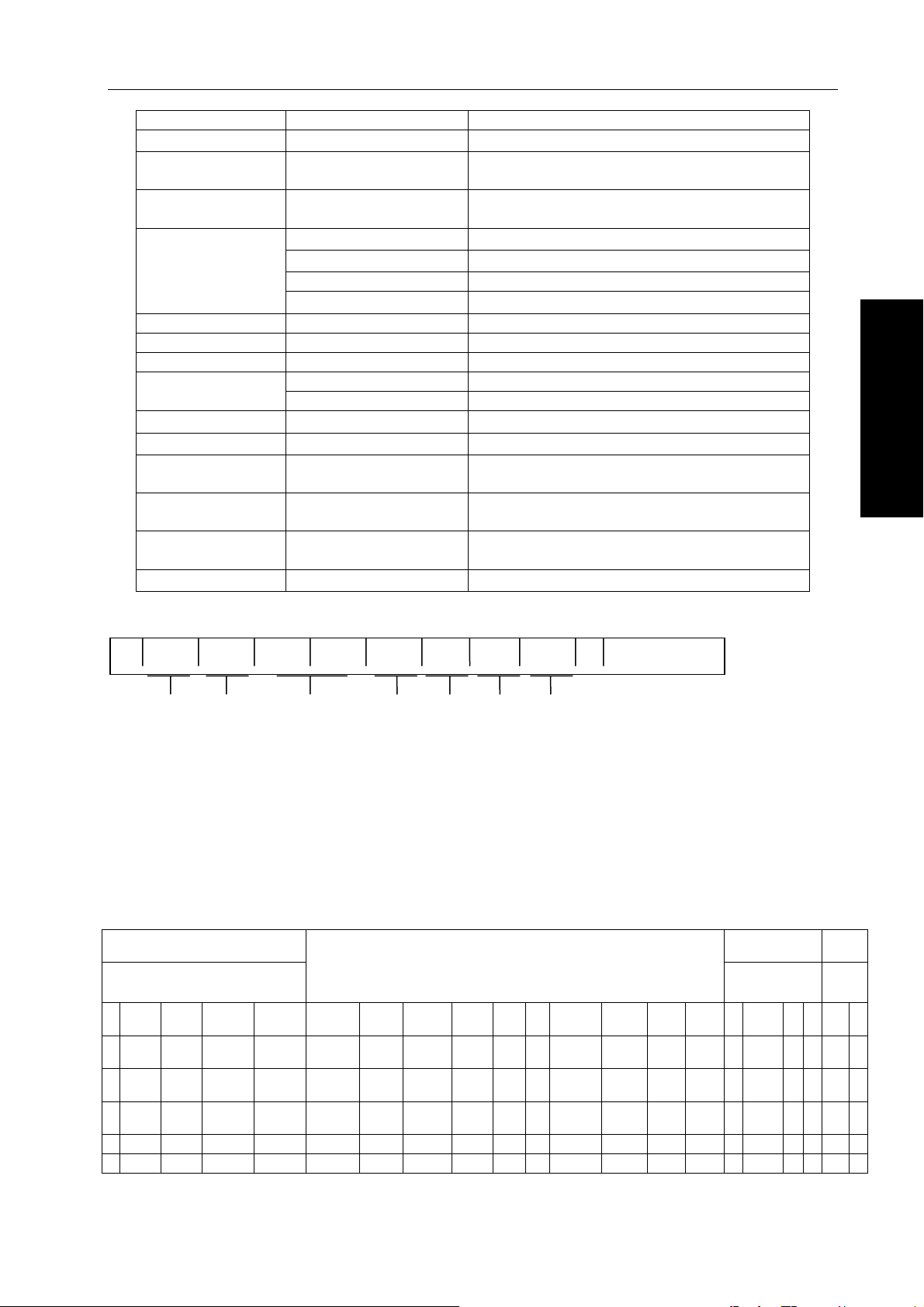
3.2.2 Program Word
The element composed with block is program word. The program word consists of the address
and its following digit. The + or – can be performed before the digit.
X - 1000
Address Digit
Program word
The address is indicated using one of the A~Z which describes the meaning of its following
umbers, the address and meaning in this NC can be used as follows. Same address may have
different meanings based on the different preparation function command in program.
14
Page 25
Chapter Three Programming
Name Address Meaning
Program number
Sequence
number
Preparation
function
Coordinate word
Feed function F Feedrate specification
Spindle function S Specify a spindle rotation speed
Tool function T Specify the tool number or tool offset number
function
Offset number
Dwell
Specify a program
number
Specify a
sequence number
Times of repetition L
Parameter
For example, the following block can be formed using these program words.
; N— G— X— Y— F— S— T— M— ;
Sequence number
Preparation function
In the following blocks, one row means one block, one grid of a block means a program word.
Name S57.10.10
Program number 0(:)
2002
/ N G X Y Z A/B/C C/V/W R/I J K F S T M B H/D LPQ
:(ISO)/O(EIA)
N Sequence number
G
X、Y、Z
A、B、C、U、V、W
R Arc radius
I、J、K
M Specify the ON/OFF of the machine tool sideMiscellaneous
B Such as the table index
H、D
P、X
P Specify a subprogram number
P
P、Q、R
Coordinate number
Feed function
Spindle function
Program number
Command motion mode (linear, circular arc
etc.)
Movement command of coordinate axis
Movement command of additional axis
Coordinate of circular arc center
Specify an offset number
Specify a dwell time
Specify a sequence number; the program is
repeatedly performed in this number.
The repetition count of program, the
repetition of canned cycle.
Parameter of canned cycle
Tool function
Micellaneous function
Pag
e /
Part 1 Programming
;
N20 G92 X
100.0 Y 200.0 Z 300.0
N21 G00 X
196.0 Y 315.0 Z 500.0
N22 G01 F10.0
S400 T15 M03
;
;
;
Note: CR(EIA),LF(ISO)
15
Page 26

GSK983Ma Milling Machine Center CNC System User Manual
3.2.3 Input format
Each program word is composed of a block which must be specified in terms of the following
description. This input format of this system is a changeable block format, therefore, both the number
of program word of a block and the character number of one program word which can be changed, in
this case, it is very convenient for programming.
Part 1 Programming
(1) Input in metric
NO4·G02·XL+053·YL053·ZL+053·
RD053 D02
αL+053·βL+053· ·F050· ·
ID053·JD053·KD+053 H02
S02 T02
· ·B03·M02;
S04 T04
(2) Input in inch
NO4·G02·XL+044·YL+044·ZL+044·
RD044 D02
αL+053·βL+053· ·F032· ·
ID044·JD044·KD044 H02
S02 T02
· · B03·M02;
S04 T04
Note 1: α or β is one of the additional axes A, B, C, U, V and W.
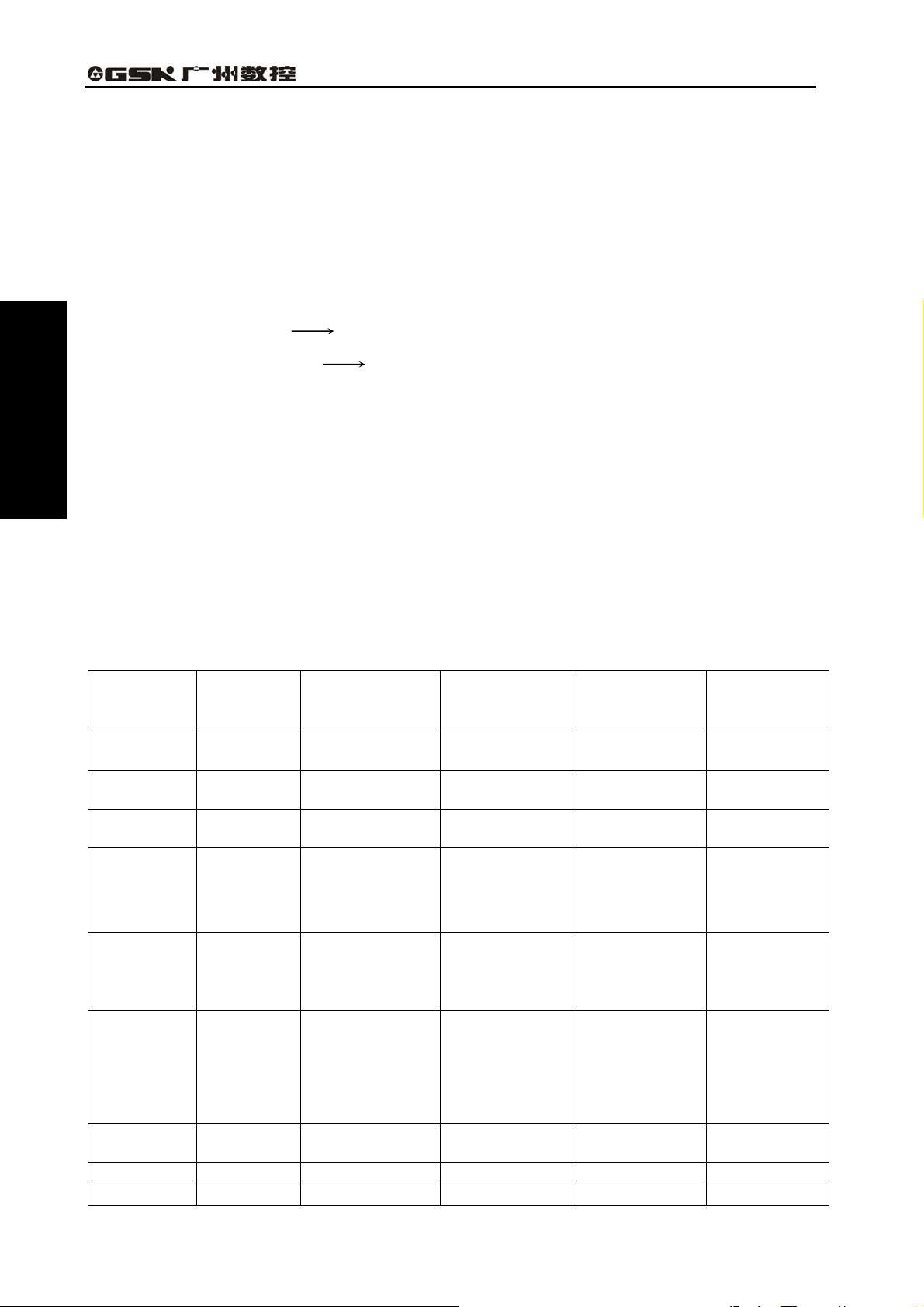
Note: The addresses and meanings which are described above format are shown below:
X L + 0 5 3
Three digits following with the decimal point
Five digits before the decimal point
Leading zero can be omitted
With symbol
Absolute or incremental
Address
J D 0 5 3
Five digits before the decimal point
Leading zero can be omitted
Incremental with symbol
Address
Three digits following with the decimal point
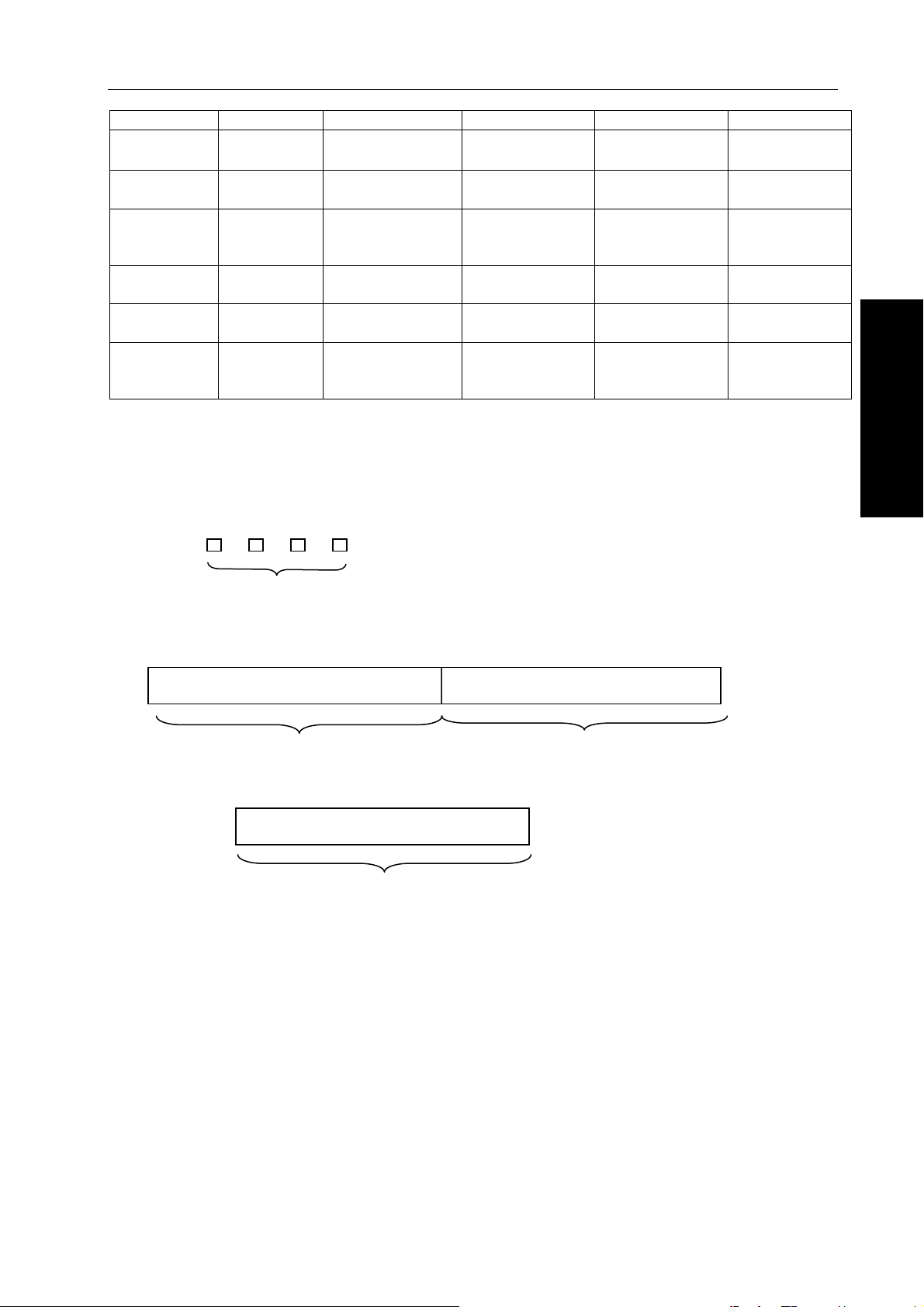
For example: when the tool move to the 50.123mm along X-axis at the rapid traverse rate, and its movement
command is as follows:
16
Page 27

Chapter Three Programming
G00 X50 . 123
Three digits following with the decimal point
Five digits before the decimal point is 00050.
Leading zero is omitted
G00 can not be omitted (G00 specifies a rapid feed) even if the
leading zero is omitted.
Note 3: When an address is specified twice at one block, in principle, the last command is enabled, and
the alarm does not perform.
For example: G01 M03 S200 M08;
In this case, M08 is enabled, and the M03 is invalid. G code of each group in a block is valid which is
specified at last. G90/G91 is in a block, which is separately valid in its specified place. (See the Section 3.3.8)
For example: G90 X10.0
Absolute Incremental
R is always valid when the R and I, J or K are specified simultaneously in circular arc interpolation
command, which is regardless of the command sequence.
Note 4: F050 can be changed into F051 in metric input format. Refer to the [Section 3.4.3 for the feedrate x
1/10].
Note 5: P or Q is omitted in the above-mentioned format due to it owns several meanings.
Note 6: When inputting in decimal point, refer to the [Section 3.2.4 for the decimal point input].
Note 7: The number input in metric, namely, X, Y, Z, A, B, C, U, V, W, I, J, K, Q, and R are set by parameter
which multiplies 10 times.
RD052
XL+052·YL+052·ZL+052·αL+052·βL+052·
ID052·JD052·KD052
(α or β is A, B, C, U, V or W) (input in metric), refer to the [Section 3.3.2.2, the input unit multiplies 10]
Note 8: Refer to the [Section 3.3.2.2, the input unit multiplies 10].
G91 Y20.0 ;
Part 1 Programming
3.2.4 Decimal point programming
Numerical values can be entered with a decimal point for this device. A decimal point is used for
the number of which is regarded as a unit of the distance, time or speed. However, some addresses
can not input in decimal point, the position of decimal points are indicated the one of the mm, inch,
degree or second.
X15.0 X15mm or x15inch
F10.0 10mm/min or 10inch/min
G04X1. Dwell 1s
B90.0 B90deg
Decimal points can be inputted the following address:
X、Y、Z、A、B、C、U、V、W、I、J、K、R、Q、F
X, Y, Z, A, B, C, U, V, W, I, J, K, R, Q, F
Note 1: When the dwell is specified, X, but P, can be input in the decimal point. (Because the P can be
specified in the sequence number)
Note 2: Change the position of decimal point using the G code, the G code should be specified in
advance even in the same block. G20: (Specify in metric)
X1.0G04;……The X1.0 does not indicate a time instead of a movement distance (inch), as for the
X10000G04, its dwell time of the consequence is 10 seconds.
When G04 is inputted, the display becomes 10.0 from 1.0.
G04X1.0: …… is regarded as G04X1000, the dwell time of its consequence is 1 second.
Note 3: Note that it is a large difference with or without decimal point; the program is different from the
electronic-computer.
G21: (Specify a metric)
X1.……X1
X1……X0.001
G20: (Specify an inch)
X1.……X1inch
17
mm
mm
Page 28
GSK983Ma Milling Machine Center CNC System User Manual
X1……X0.0001inch
Note 4: The numbers can be used with or without the decimal point
X1000 Y23.7;
X10 Y22359;
Note 5: If the value specified is less than the value of the least input increment, and this value is then
omitted. When the X1.23456 is specified, it is treated as X1.234 in metric, and it is regarded as
1.2345 in inch. The accumulation error occurs when the incremental value is specified, the
accumulation error does not issue but its error omitted when the absolute value is specified.
The specified digits can not exceed the maximum allowance digits.
X1.23456789……has an error due to it exceeds 8 digits.
X1.2345678……does not an error because it is within the 8 digits.
Note 6: When a number with a decimal point is input which is converted into an integer of the least
Part 1 Programming
number is more than 8 digits.
input increment.
(For example) X12.34 12340 (Input in Metric)
The converted integer should be checked, still.
(For example) X1234567.8 X1234567800 (Input in Metric). The alarm may occur due to this
3.2.5 The maximum command value
Note that the maximum commanded value range of NC device is expressed in the following table
instead of the mechanical movement range of NC machine. For example, the movement of X axis for
the NC device is about 100m (Input in Metric). As for a certain machine, the stroke distance of X axis
may limit within 2m, as the feedrate. The cutting feedrate of NC device can be set to 30m/min, but the
NC machine side may limit within 6m/min. In the actual programming, refer to this manual and the
manual issued from the manufacturer at the same time. Program can be performed after
comprehending the special machine program fully. The maximum command value of each address is
shown below:
Table 3.5 The basis address and the range of command value (the additional selection
included)
Input in inch
±3937.0078in
0.01inch/min
1200.00inch/
0.01inch/min
1200.00inch/
Name Address
Program
number
Sequence
number
Preparation
function
:(ISO)
O(EIA)
N
G
X、Y、Z、I、
Coordinate
word
J、K、Q、R、
A、B、C、U、
V、W
Feed per
minute
F
Feed per
minute
(feedrate
1/10)
F
(Parameter
setting)
Spindle
function
S
Tool function T
Miscellaneo M
18
Input in mm
Output in mm
1~9999
1~9999
0~99
±99999.999mm
±99999.999°
1 mm/min~
30000mm/min
0.1 mm/min~
30000.0mm/min
Input in inch
Output in mm
Input in mm
Output in inch
As the left As the left
″ ″ ″
″ ″ ″
±3937.0078inc
h
±99999.999°
0.01 inch/min~
1200.00inch/mi
n
0.01 inch/min~
1200.00inch/mi
n
±99999.999mm
±99999.999°
1 mm/min~
30000mm/min
0.1 mm/min~
30000.0mm/min
0~30000 0~30000 0~30000 0~30000
0~9999
0~99
″ ″ ″
″ ″ ″
Output in
inch
As the left
ch
±9999.999°
~
min
~
min
Page 29
Chapter Three Programming
us function
Dwell X
Dwell P
0 s~
99999.999s
0ms~99999999
ms
″ ″ ″
″ ″ ″
Sequence
number
P
1~9999
″ ″ ″
setting
Times of
repeated
Offset
number
L
D、H 0~184
1~9999
″ ″ ″
″ ″ ″
The 2nd
M.S.T
B
0~999
″ ″ ″
function
3.2.6 Program number
This controllable device can be stored several programs into the NC memory, the program
number is added to each program to distinguish these programs.
Program number
O The solution range is from 1 to 9999, the leading zero can be
omitted. (Program O0000 is used for transforming during the
program replication.)
4 digits
Program starts at the beginning of the program number which ends till met the M02, M30 or M99.
The program of O1111 The program of O2222
01111………………………M02; 02222………………………M30;
M02 and M30: the end of main program. M99: the end of subprogram.
05555………………………M99;
The subprogram of O5555
Note 1: The “:” before the program number is replaced by “O” in ISO code.
Note 2: The block of the code with optional block skip, such as /M02; /M30 or /M99 which can not treat
as an end of program.
Note 3: When the program number does not at the beginning of the program, the first sequence number
of this program (N…) can be replaced by the program number, but the NO program number is
unallowable.
Note 4: If neither the program number nor the sequence number is performed at the beginning of the
program, the program number should be specified by the MDI & LCD panel when the program is
stored to the memory.
Note: When several programs are performed, the EOB code without a flag is skipped after the 2
program and before its followed program, but the end of the previous program is finished by the
ER (EIA) RO % (ISO), the program at its beginning should be used the EOB code.
Note 6: The run can be performed without a sequence number. However, the subprogram must always
have a program number.
Note 7: In some cases, the program numbers from 9000 to 9899 are used for the manufacturer, but the
user can not employ it.
nd
Part 1 Programming
19
Page 30

GSK983Ma Milling Machine Center CNC System User Manual
Note 8: When the selection is performed by the manipulator, the program numbers 9900~9999 are used
as a manipulator data.
Note 9: M02, M30 or M99 does not performed at the end of a program, which is followed with ER (EIA) %
(ISO) or next program number 0, the end of program is set by BIT3 (NEOP) of parameter 306.
Note 10: When the maloperation is performed to cause the program is more than 4 digits, the program
may not call for the subprogram. In this case, the characters more than 4 digits are deleted.
Deletion method: editing-> program lock open-> move the cursor to the program O-> insert the
“EOB”-> move the cursor to the program O again-> press “deletion” key after the “EOB” is
pressed.
3.2.7 Sequence number
Part 1 Programming
At the beginning of the block, the numbers 1~9999 within 4-digit followed with address N can be
specified the sequence number, and the sequence of its sequence number is optional. Either the
sequence number can be performed for all the blocks, or the sequence number is added at the
required place during program.
The sequence number should be continuously specified in the key place, for example, when a
new tool is used when it is used, or the working table index transfers to the new machining surface.
Note: For compatibility with other program formats of NC device, the sequence number N0 does not used
3.2.8 Skip to optional block
The slash /n (n=1~9) followed with numbers are specified at the beginning of the block, and
when the skip optional block switch n is ON, during the DNC operation or automatic operation, the
block with /n corresponding to the switch number n is then ignored.
The block with /n is enabled after the skip optional block n is OFF. Namely, operator can
alternatively select the skip block which with /n. The 1 in the /1 can be omitted, however, it can not be
omitted when there are 2 or above skip optional block switches at the same block.
When the optional block switch is ON, the ignored area is shown below:
;/2N123G01X4……………………;N7856
Ignored area
For example:N100X100;
N101/2z100;
N102/2/3X200;
N103/3z200;
In the above-mentioned example, when the No.2 switch is ON, the blocks N101 and N102 are
skipped; and when the No.3 switch is ON, the blocks N102 and N103 are skipped.
Note 1: The slash (/) must be placed at the beginning of the block, if it is placed at other places, the
information in which from / to the EOB code is then omitted, and the information in the front of the / is
still effective.
Note 2: The TH and TV are still checked to the skipped part while the skip optional block switch is opened,
which is same as the switch OFF.
Note 3: The block to be skipped is identified when the memory transfers the information to the buffer. When
the block in front of the / has been read into the buffer, this block may not be ignored even if the
optional block switch is ON.
Note 4: This function is enabled during the sequence number is indexed.
Note 5: This function is disabled when this program is registered to the memory. The / followed with a block
can be read into a memory regardless of the switch of skip optional block.
Note 6: When the program is output from the memory, the program can be completely output regardless of the
state of skip optional block switch.
Note 7: Some skip optional block switches (from 1 to 9) may not used for some machines. So, it is necessary
to inquire the manufacturer how many switches can be used before operating.
Note 8: The system with the function of additional skip optional block, if a block is more than a flag of skip
optional block, the 1 of /1 can not be omitted, the /1 may specify in terms of the above-mentioned
notes.
For example Wrong: //3 G00 X10.0;
Correct: /1/3 G00 X10.0;
20
Page 31

Chapter Three Programming
3.3 Dimension Word
The dimension word decides the movement of tool, which is composed some commands relative
to the numerical value by the address of movement axis and the numerical value indicates the
movement direction and quantity. They may vary from the absolute and increment modes. (See the
Section 3.3.8)
Dimension word address Meaning
The address in the Cartesian coordinate system of each
Basic axis
Additional axis
interpolation
parameter
3.3.1 Controlled axis
X、Y、Z
A、B、C、U、V、W
R Specify a circular radius Circular arc
I、J、K
axis indicates the position of axis or the distance along the
axis direction.
The address of the 4
th
or 5th axis, which means an angle of
rotation axis or a position and a distance of linear axis
separately.
It means that the distance from start to circular center along
the X, Y and Z axes or its parallel axis.
Part 1 Programming
The machine movement axis controlled by the NC system is called controlled axis.
Each controlled axis can be called using the dimension word address of this device.
The numbers of standard axis controlled by NC system are 3 axes (X, Y and Z) and can be
added to the 4
th
axis or the 5th axis.
The additional axis can be used any of the addresses, such as, A, B, C, U, V or W, it is better to
use A, B and C for the rotation axis, and use U, V and W for the linear axis.
The numbers of controlled axis can be controlled at the same block which is 3 axes. The number
of simultaneously controllable axes can be added to 4 by the additional axis selection, the additional
axis by controlling singly is only used for the simultaneous 3 axes control. The 3 axes control with an
additional axis can be carried out, after the function of additional axis control is selected.
The numbers of simultaneous controlled axes
The numbers of
Simultaneous 3
controlled axes
axes selection
Simultaneous 3 axes selection +
Simultaneous 4
additional axes simultaneous
axes selection
controlled selection
3
4
5
Note 1: When an additional axis control function does not performed, if an additional axis (A, B, C, U, V or
W) is carried out, the No.17 alarm may occur.
Note 2: The numbers of simultaneous axes are always 2 axes during the manual operation.
Note 3: The following functions can not be performed when the system has the 5th axis.
① Never attempt to perform the thread cutting and synchronous feed.
② Never attempt to add the S4 digit analog output function (The spindle DA (digital-analog
conversion) module substitutes for the output analog function).
The constant surface speed cont③ rol function can not be added.
Do not perform the rigid tapping function④
The real⑤ -time spindle actual speed can not be displayed.
3
X、Y、Z
(The additional axis included)
3
4
The coordinate axes and motion symbols
If the relationships between machine coordinate axis and tool movement symbol are provided
21
Page 32

GSK983Ma Milling Machine Center CNC System User Manual
with the machine, the serious mess may occur in programming, which the relative explanations have
been described in the EIA RS-267-A or ISO841.
However, the following explanations should be noticed during programming:
a) The program should be programmed based on the standard coordinate system (Right-hand
Cartesian coordinates);
b) In programming, suppose that the workpiece does not move but the tool moves round with the
workpiece
Part 1 Programming
3.3.2 Setting unit
3.3.2.1 The least input increment and the least movement unit
1) The least input increment (Input unit)
Input the least units of tool movement amount by the command, which are registered in mm, inch
or deg.
2) The least movement unit (Output unit)
The least movement units input to the machine are indicated in mm, inch or deg. Any of the
22
Page 33

Chapter Three Programming
following groups can be adopted.
The least input
The least
Input/output
increment
movement unit
Input in mm, output in mm 0.001mm 0.001mm
Input in inch, output in mm 0.0001inch 0.001mm
Linear
axis
Input in mm, output in inch 0.001mm
0.0001inch
Input in inch, output in
inch
0.0001inch
0.0001inch
Rotation axis 0.001° 0.001°
Note: The increment system of rotation axis can not be converted in inch/metric system.
Whether the least movement unit is based on 0.001mm or 0.0001 inch which is determined by
the machine and it can be selected by the presetting BIT0 (SCW) of parameter 006.
The least input increment is 0.001mm or 0.0001inch can be selected by the G code or the
parameter setting of MDI & LCD panel.
G20 the least input increment of linear axis is 0.0001inch.
G21 the least input increment of linear axis is 0.001mm.
The G20 or G21 is unchangeable when the system is ON or OFF.
Part 1 Programming
3.3.2.2 10 folds input unit
The least input increment in mm can be changed into 0.01mm using the BIT 1 of parameter 006,
which the unit in inch can not be changed.
Address
Dimension word
Rotary axis
Dwell time
X、Y、Z、Q、R、I、J、K、U、V、W
A、B、C
X
P
It can not be changed in the following cases:
a) When the input is different from the above-mentioned dimension word.
b) Display unit
c) The maximum command value range.
d) Increment feed unit and manual feed unit
e) Offset input
The least input increment
Input in mm Input in inch
0.01mm
0.0001inch
0.01° 0.01°
0.01s 0.001s
0.01s 0.001s
f) Others
Note 1: The input unit is either 0.0001inch or 0.001mm in the latter explanations in the manual.
Note 2: The display unit changes into 0.01mm or 0.01deg by setting the BIT 2 (MDL) of parameter 006.
23
Page 34

GSK983Ma Milling Machine Center CNC System User Manual
3.3.3 The maximum stroke
The maximum stroke can be commanded in this device is shown below:
Input/output in
mm
±99999.999mm
±99999.999°
Part 1 Programming
Note: The above-mentioned strokes vary from one machine to another.
3.3.4 Program origin and coordinate system
The program origin and coordinate system can be affirmed during programming. Usually, some
point on workpiece is set to a program origin.
Input in inch/
output in mm
±3937.0078inch
±99999.999°
Input in mm/ output
in inch
±99999.999mm
±99999.999°
Input/output in
inch
±9999.9999inch
±99999.999°
This is an example of that coordinate system is a workpiece coordinate system
3.3.5 The coordinate system and the machining start point
The workpiece coordinate system should be used while the program is sent to NC, tool and
program are operated from the start point. However, NC must be realized the tool’s coordinate value
at its start point by the G92 code (coordinate setting).
24
Page 35

Chapter Three Programming
3.3.6 Workpiece coordinate system
Several workpieces have been installed in machine, which the installation positions of these
workpieces are different; therefore, several workpiece coordinate systems should be applied. In this
case, 6 coordinate systems set in the machine in advance which can be selected by the 6 G codes
(G54~G59), the followed program is performed within the selected coordinate system, each
coordinate system can be determined by the distance from the reference position (the fixed point on a
machine) to its coordinate origin along with each axis, refer to the following figure.
The setting of workpiece origin offset, refer to the Section 4.4.13.
Part 1 Programming
When using the above-mentioned workpiece coordinate system, establish a coordinate system
without using a G92 code. The coordinate system set by G92 which is replaced by G54~G59.
Generally, G92 does not perform together with G54~G59.
Note: When using the coordinate system set by G54~G59, return to the 1st reference position after the
power is turned on, a workpiece coordinate system can be automatically set by G54, so the
automatic coordinate system need not to be set.
3.3.7 Reference (position) point
Reference position is a fixed on a machine tool to which the tool returns to the reference position
by the reference position return function. So, the program can not be started from a certain point on
workpiece coordinate system, but it can be started from a reference position. In this case, because
the reference position is a certain point on the machine, and the program is organized based upon the
point on the workpiece is regarded as an origin. Therefore, the tool returns to the reference position
25
Page 36

GSK983Ma Milling Machine Center CNC System User Manual
which must be described in workpiece coordinate system using G92 code.
Y
Part 1 Programming
α
Program origin
β
Reference point
Workpiece
X
G92 Xα Yβ ;
Note: When using the workpiece coordinate system set by G54~G59, G92 is unnecessary.
3.3.8 Absolute and incremental commands
The tool operation distance of each axis can be programmed in incremental or absolute
commands.
The operation distance can be programmed directly in a block by the increment command (G91).
Tool end position in a block is expressed by the coordinate value in the workpiece coordinate
system.
The above figure is carried out by the increment command program:
G91 X-60.0 Y40.0;
However, it is carried out by the absolute command program:
G90 X40.0 Y70.0;
In order to make a compatibility with other NC systems for the program, each address in block
can not changed the G90/91 command method.
26
Page 37

Chapter Three Programming
3.4 Feed Function (F function)
3.4.1 Rapid traverse rate
In the rapid traverse rate, the machine of each axis moves based on the specified speed.
In general, the rapid traverse rate is set by the manufacturer. (It is set by the parameter 092~095,
428, and from RPDFX to RPDF4).
Each axis of machine is separately moved, so these axes are moved from start to end which are
spent different time.
For example: When the rapid traverse rate of X and Y axes are separately 5000mm/min and
8000mm/min, and the operation programs are shown below:
G91 X2000.0 Y2000.0;
The X and Y axes on the machine tool are operated in the time of 24s and 25s where from start
to end.
The tool path on the above figure is shown below:
Part 1 Programming
The override control of rapid traverse rate can be carried out by the switch on the machine
operator panel. (F0, 25%, 50%, 100%) F0 is determined by the parameter 113 (SPDFL), and its unit
is not indicated by the percentage (%), instead of the mm/min or inch/mm.
3.4.2 Cutting Feedrate
Specify a tool cutting feedrate based upon the feed distance of each minute, the feedrate is
specified with F which is shown below:
F1(1mm/min,0.01inch/min)
F15000(15000mm/min)or F60000(600.00inch/min)。
27
Page 38

GSK983Ma Milling Machine Center CNC System User Manual
This feedrate is clamped at the upper limit (maximum) value
This upper limit value (the maximum value) can be set by the parameter 106 (FEDMX) by the
manufacturer, the feedrate is also controlled to the override from 0 to 200% (10% for each step) by
the switch from the machine operator panel. The claming of the upper limit speed is also effective to
the override feedrate. Specify the feedrate by F code is suitable for the rotation axis, too.
For example: Metric input F050
Inch input F032
Part 1 Programming
The decimal point input is available when inputting in metric or inch, and the decimal point are at
the place of degree/minute.
Metric input F12 0.12deg/min
Inch input F12 0.12deg/min
Metric input F12.0 12deg/min
Inch input F12.0 12deg/min
Note 1: Except the procedure of acceleration/deceleration in NC operation,
Note 1: The calculation error of the command feed where from NC holds the within ±2% of the command
feed, and the error is calculated by spending the time for measuring the movement distance which is
more than 500mm, where is followed with the NC steady state.
Note 2: Up to 7 digits can be performed for the F code, if the inputted feedrate is more than the upper limit
value, which will clamp at this value if the movement command is performed.
3.4.3 Feedrate decelerates to 1/10
The metric speed input can be changed into 1/10 by the setting of BIT 3 (FMIC) of parameter
006.
Description The least input unit Range
Feed/min. 0.1mm/min
F1~F150,000 (0.1 mm/min~15000.0mm/min)
3.4.4 Synchronous feed (feed/rev.)
Specify the feedrate based on the spindle feed/rev. G95 specifies the synchronous feed; and
G94 specifies the feed/min. (The movement amount in minute is a feedrate.)
Feed/min. Synchronous feed
Meaning Tool feed amount in minute
Address F F
G code G94 G95
Input in
1 mm/ min~30000 mm/ min
Solution
mm
28
(F1~F30000)
Tool feed amount of spindle of
each revolution
0.01 mm/r~1000.00 mm/r
(F1~F100000)
Page 39

Chapter Three Programming
Input in
inch
0.01inch/ min~1200.0inch/ min
(F1~F60000)
0.0001inch/r~100.0000inch/r
The feed in minute and the synchronous feed are generated a clamping at a certain
Clamping
feedrate, this clamping value is set by the manufacturer (the feedrate with override
value
can be clamped only.)
Override
The override (10% for each gear) from 0 to 200% is valid to the feed/min. and the
synchronous feed.
The clamping value is set based on the mm/min or inch/min. The synchronous feedrate changes
into mm/min or inch/min as the following equations.
fm=fr×R
Wherein, fm: The unit of the feedrate per minute is mm/min or inch/min
Fr: The unit of synchronous feedrate is mm/r or inch/r.
R: The unit of spindle speed is r/min.
Note 1: G94 and G95 are modal, which are valid after the specification is performed once till the other G
codes are generated.
Note 2: The synchronous feed must be performed with the spindle installed a position encoder.
Note 3: It also can be used when the position encoder speed is up to 1r/min., the feedrate maybe irregular,
which does not affect the machining. However, the abnormity can not continue, otherwise, the
unexpected behavior may occur along the decrease of the speed.
Part 1 Programming
3.4.5 F1-digit Feed
One-digit number from 1 to 9 F is specified after F, namely, the feedrate corresponding this
number is set. Each number has been set its corresponding parameter in advance. The F0 is
regarded as a rapid traverse rate. After the F1-digit feedrate switch installed on the machine panel is
shifted ON, the feedrate corresponding to the number currently selected can be increased or
decreased by rotating the MPG.
The increment/decrement of feedrate
F
MAX
100
1
/per scale of the MPG]
X
F=△
Wherein:
F
: It is used for the feedrate upper limit of F1~F4 ------ it is set by parameter #171~
MAX1
174(FIDF1~4);
: It is used for the feedrate upper limit of F5~F9------ it is set by parameter #1751~
F
MAX2
179(FIDF5~9);
X: any number among 1~127 set by parameter.
The feedrate set or altered is kept even while the power is OFF. The current feedrate is displayed
on the LCD.
29
Page 40

GSK983Ma Milling Machine Center CNC System User Manual
3.4.6 Automatic acceleration/deceleration
When the feed is started or stopped, at a certain time constant, the automatic acceleration or
deceleration is performed to avoid the mechanical system vibration occur. Therefore, the acceleration
or deceleration may not perform during programming.
The pointed corner can not be machined due to the automatic acceleration or deceleration, the
dwell command code (G04) is added between two blocks to machine a sharp corner.
Part 1 Programming
The actual tool path is fit to the programmed one after the dwell command is inserted. The faster
the feedrate rotates, the bigger the acceleration/deceleration tome constant occurs, the bigger the
corner error is.
Note 1: The feedrate changes between the blocks of the specified different movement, as follows:
The previous block
New block
Positioning × × ×
Cutting feed × ○ ×
Not move × × ×
×: The next block is performed after the command speed is decelerated to zero.
○: Continue to perform the next block, so that the feedrate is not changed widely.
Note 2: The deceleration is performed on each axis separately (X or Z axis) and the feedrate of each axis
may occur between blocks. Therefore, the actual tool path does not match for the programmed
path. For example, if the tool only moves along X axis in a block, and along Z axis in the next
block, it is then decelerated along with the X axis direction nearby the corner, and then
accelerated along the Z axis direction. The actual tool path is shown below:
Positioning Cutting feed Not move
In the circular arc interpolation, the actual arc radius should be less than the programmed one (refer to
the appendix), this error can be carried out by reducing the time constant of acceleration or deceleration as
much as possible.
30
Page 41

Chapter Three Programming
3.4.7 Automatic Corner Modification
If the tool is performed a tough machining with tool compensation based on the program feedrate
within the inner corner and inner circular arc area, the tool cutting overload may occur. This function
can be automatically decrease the feedrate to reduce the overload of tool in the above-named area,
so than the smooth machining surface can be carried out.
3.4.7.1 The automatic modification of inner corner
1) Working conditions
When two blocks (the previous one and the latter one) are available for the following conditions,
the feedrate can be achieved the automatic modification.
a. G codes of group 01 are G01, G02 or G03.
b. In the offset mode, the value of offset does not 0.
c. The offset should be performed within the machining corner
d. The axis moves along with the offset surface.
e. G41 and G42 command codes are not performed in the following blocks.
f. G41 and G42 command codes are not performed in the previous blocks. Or, if the two
blocks are performed, this block does not start.
g. The inner corner is less than the θ set by parameter in advance.
The angle of programmed path
(I) Straight line to straight line
Part 1 Programming
(II) Straight line to arc
(III) Arc to straight line
31
Page 42

(IV) Arc to arc
Part 1 Programming
When θ≤ΘP, which is treated as an inner corner. The value of θP is set by parameter (NO·335)
GSK983Ma Milling Machine Center CNC System User Manual
(1°≤θP≤179°). Suppose that the θ and θP are equivalent, the estimation error less than 0.001° may
occur.
2) Operation range
After the corner is affirmed to an inner one, the feedrate is modified from the corner range from
Le in the corner intersection block to another. The straight line distance between Ls and Le is the
point from tool center path to the corner intersection. Le and LS are separately set by the parameters
(#355 and #356)
The feedrate is modified within the range from a to b.
The feedrate is modified within the range from a to b.
As for the circular arc, this modification is effective for the EOB based on the following conditions.
① Distance within Le.
32
Page 43

Chapter Three Programming
The start and end points of circular are located on the same quadrant or the start is situated at ②
the adjacent one of the end quadrant.
The modification function of the start of the block is enabled based on the following conditions.
Distance within Ls.①
The start and end points of circular are located on the same quadrant or the end is situated at ②
the adjacent one of the start quadrant.
(For example) The circular disk
Part 1 Programming
The feedrate is modified from a to b and c to do for the program of an arc.②
3) Modification value
The modification value is set by the parameter #334.
1≤AOVOR (each gear 1%) ≤100 (%)
It is also enabled for the dry run and the F1-digit command. In the case of the F4-digit command,
the actual feedrate is as follows:
Fx (AOVOR) × (Feedrate modification)
4) Whether the inner corner modification is enabled
The inner corner modification can be determined by the G code, in the group 15, add the G62
between the G91 and G64, refer to the following table. These G codes are related with the exact stop
check mode.
Exact stop check Inner corner modification
G61 Enabled Disabled
G62 Disabled Enabled
G64 Disabled Disabled
Note 1: G64 state is performed when the power is turned on or off.
Note 2: G09 must be specified if the exact stop check is performed in the mode of G62.
Note 3: The inner arc cutting feedrate change is always effective which is not affected by the G codes,
refer to the Section 4.7.2.
3.4.7.2 The change of inner side arc cutting
In the case of the inner side arc offset cutting, the feedrate of programmed path is specified by
33
Page 44

GSK983Ma Milling Machine Center CNC System User Manual
the F code, and the actual feedrate is F×RC/RP (wherein, RC is a radius of tool center path; RP is a
radius of program path).
This change is also valid to the dry run and F1-digit command.
(For example 1)
Part 1 Programming
However, if RC is much smaller than RP, namely, RC/RP=0, the tool may stop then. Therefore,
after the least deceleration rate is set, when RC/RP≤AOVMDR, the actual feedrate is FX (AOVMDR).
The MDR is determined by the parameter #333. 1≤AOVMDR (each gear 1%) ≤100, which is also
used for F1-digit and the dry run. The acceleration rate of inner corner automatic modification is not
affected by the AOVMDR.
Note: If the inner side arc cutting is overlapped at the inner corner automatic modification, in this case, the
actual feedrate is F×
Rc
× (corner modification) × (feedrate override).
Rp
3.5 Preparation Function (G function)
Two numbers following address G determines the meanings of the command for the concerned
block.
G codes are divided into the following two types:
Type Meaning
One-shot G code The G code is effective only in the specified block.
Modal G code
(Example) G01 and G00 are modal G codes.
The G code is effective until another G code of the same group is
specified.
G01 X ;
Y ; G01 is valid in this range
X ;
G00 Y ;
34
Page 45

Chapter Three Programming
Table 3.5.1 G codes
G code Group Function
G00 Positioning (rapid traverse)
G01 Linear interpolation (feed)
G02 Circular interpolation CW (Clockwise)
G03
G04 Dwell
G07
G09 Exact stop check
G10
G17 XY plane selection
G18 ZX plane selection
G19
G20 Input in inch
G21
G22 Stored stroke limit ON
G23
G27 Reference position return check
01
00
02
06
04
Circular interpolation CCW (Counterclockwise)
Speed Sine curve control (Specify an imagination
axis)
Offset setting, workpiece zero offset setting
YZ plane selection
Input in mm
Stored stroke limit OFF
Part 1 Programming
G28 Return to the reference position
G29 Return From reference position
G30 2nd, 3rd and 4th reference position return
G31
G33 01 Thread cutting
G40 Tool compensation cancel
G41 Tool compensation – left side
G42
G43 Tool length compensation + direction
G44 Tool length compensation - direction
G49
G45 Tool position offset increase
G46 Tool position offset decrease
G47 Tool position offset double increase
G48
G50 Scaling off
G51
00
Skip cutting
07
Tool compensation – right side
08
Tool length compensation cancel
00
Tool position offset double decrease
11
Scaling on
G54 Workpiece coordinate system 1 selection
G55
35
14
Workpiece coordinate system 2 selection
Page 46

GSK983Ma Milling Machine Center CNC System User Manual
G56 Workpiece coordinate system 3 selection
G57 Workpiece coordinate system 4 selection
G58 Workpiece coordinate system 5 selection
G59 Workpiece coordinate system 6 selection
G60 00 Single direction positioning
G61 Exact stop check mode
G62 Automatic corner modification valid
Part 1 Programming
G64
G65 00 Simply call the Marco command
G66 Marco command modal call
G67
G68
G69
G73 Peck drilling cycle
G74 Counter tapping cycle
G76 Fine boring
G80 Canned cycle cancel
G81 Drilling cycle, spot boring
G82 Drilling cycle, counter boring
G83 Peck drilling cycle
G84 Tapping cycle
G85 Boring cycle
15
Cutting mode
12
Macro command modal call cancellation
Coordinate rotation ON
16
Coordinate rotation OFF
09
G86 Boring cycle
G87 Counter boring cycle
G88 Boring cycle
G89
Boring cycle
G90 Absolute command
03
G91
Increment command
G92 00 Setting for work coordinate system
G94 Feed per minute
05
G95
Feed per rotation
G98 Return to the initial point in canned cycle
10
G99
Return to point R in canned cycle
G96 Constant surface speed control
13
G97
Constant surface control cancel
G180 Cancel the rigid tapping in canned cycle
22
G184
Rigid tapping cycle
36
Page 47

Chapter Three Programming
Note 1: The G code with is a start G code of each group. Namely, when the power is turned on or the
resetting key is controlled when the system parameter of G code is specified, the G codes are set
up therefore. As for the G22 and G23, the G22 is selected when the power is turned on, G22 or
G23 (one of them is effective before resetting) is then set up.
The selection of start G codes state, such as G00, G01, G43, G44, G49, G90, G91 or G94,G95, which
is determined by the parameter 008.
The effective one between G20 and G21 is selected before the power is turned off or the resetting
key is pressed.
Note 2: G codes in group 00 are not modal, which are only valid in its block.
Note 3: When the G codes in the above table are specified, or when an undefined optional G code is
specified to a control device, the alarm (No.0/0) may occur, but the G38 and G39 are ignored.
Note 4: Some G codes can be specified at the same block even if they are not shared the same group.
When two or more G codes in a same group are specified at the block, the last specified G codes
are effective.
Note 5: In the canned cycle mode, if any of the G codes in group 01 are specified, the canned cycle will
automatically cancelled, and the system is then on the state of G80. However, G codes in group
01 are not affected by any G codes in the canned cycle.
Note 6: G70 and G71 can be separately replaced the G20 and G21 (particular G code) by setting the BIT 5
(GSP) of parameter 008.
Note 7: G codes of each group are displayed.
Part 1 Programming
3.5.1 Plain Selection (G17, G18, G19)
Select a plain for circular interpolation and tool compensation by the commands.
G17……XY plain
G18……ZX plain
G19……YZ plain
The movement command is regardless of the plain selection of G17/G18/G19, for example,
when the G17 Z _ is specified, the Z moves.
3.5.2 Positioning (G00)
Use this code, tool positioning is performed at each point of address X, Y, Z or A, B, C, U, V and
W programming, the coordinate value must be specified in the absolute command. The distance from
start to end must be specified in the increment command, and the tool is separately moved at the
rapid traverse rate of each axis, the tool path in positioning is not always a straight line.
Two axes (2 addresses) can be programmed at the same time in a block, but, only one can be
performed for the 4
th
axis.
Specify a G00 positioning
G00α_____β_____;
(α·β=X、Y or Z)
For example: the rapid traverse feedrate is: X axis 9600mm/min
37
Page 48

GSK983Ma Milling Machine Center CNC System User Manual
The program of Y axis in 9600mm/min
G00G91 X25.0 Y-10.0
Part 1 Programming
Note 1: The rapid traverse feedrate in G00 command is set for each axis by the machine tool manufacturer,
therefore, it can not be specified by the a programming.
In the positioning of G00, the tool speeds up from the start till to the preset speed, which may rapidly
move thereafter till decelerate to the end, and the next block is performed after confirming the “appropriate
position” sequently. (Note 2)
Note 2: The “appropriate position” means that the motor feed is within the specified range (This range is
determined by the machine tool manufacturer).
Note 3: If the system is selected to a simultaneous 3 axes function which the following movement
command can be specified is shown below.
G00 X___Y___Z___;
In this example, X, Y and Z axes positions the tool to the specified location at the specified speed at the
same time.
When the system selection has a simultaneous control function of additional axis, both the address X, Y
and Z and the additional axis address are commanded. Three or four axes can be operated simultaneously if
the commands are performed.
For example: X500.0 Y300.0 Z25.0 B20.0;
3.5.3 Single Direction Positioning (G60)
The exact positioning without an offset can be finally positioned from one direction.
Start
End
(The last position direction is from right to left)
The G00 is replaced by G60:
G60 α____β____γ____δ____;
(The α, β and γ= X, Y and Z or additional axes A, B, C, U, V or W, which are controlled in 3 axes
or 4 axes. the simultaneous control occasion for the 2 axes and 3 axes are included an additional
axis).
An overrun and a positioning direction are set by parameter. Even when a commanded
positioning direction coincides with that set by the parameter, the tool stops once before the end
point.
38
Page 49

Chapter Three Programming
Note 1: G60, which is a one-shot G code.
Note 2: During canned cycle for drilling, no single direction positioning is effected in Z axis.
Note 3: No single direction positioning is effected in an axis for which no overrun has been set by the
parameter
Note 4: When the move distance 0 is commanded, the single direction positioning is not performed.
Note 5: The direction set to the parameter is not effected by mirror image.
Note 6: The single direction positioning does not apply to the canned cycles of G76 and G87
3.5.4 Linear interpolation (G01)
G01α____β____F____;
Part 1 Programming
(α. β=X, Y, Z, A, B, C, U, V or W. Additional axis is carried out a simultaneous control with other
axes).
Actually, it is specified a linear interpolation mode. The values from α and β are defined a tool
movement distance, which is treated in the mode of the absolute and increment based on the current
state of G90/G91. The feedrate is specified by F code, and the F code is modal.
Program example: (G91)G01 X200.0 Y100.0 F200.0
Y End
0 Start 200.0 X
Specify the feedrate by F code is a tool movement speed, if the F code does not specify when
the power is turned on; the feedrate is then regarded as 0.
The movement command with simultaneous 3 axes control function is shown below.
G01 X____Y____Z____F____;
Simultaneous 3 axes linear interpolation can be performed by this command.
When the additional simultaneous control function is selected, The X, Y or Z can be replaced by
th
the 4
axis address (A, B or C), in this case, the simultaneous 3 axes control of the 4th axis can be
carried out.
For example: G01 X500.0 Y300.0 B20.0 F10.0;
The following commands can be performed when the system has an optional simultaneous 4
39
Page 50

GSK983Ma Milling Machine Center CNC System User Manual
α
β
axes function.
G01α____β____γ____δ____F____;
Wherein α, β, γ, δ= X, Y, Z, A, B, C, U, V or W.
Note 1: The feedrate of each axis direction is as follows:
ββ F f;
G01αα
Feedrate of α axis direction: Fα=
Part 1 Programming
Feedrate of β axis direction: Fβ=
2
2
+
β
α
L=
Note 2: The feedrate of rotation axis can be determined by degree/minute (metric input: F050, Inch input:
For example: G91 G01 B90.0 F300;
Note 3: The 4th axis is included in the linear interpolation (Rotation axis A, B or C). The cutting feed unit
For example: G91 G01 X20.0 B40.0 F300.0;
Change the movement command unit (degree) of B axis into mm or inch, the machining time is as
follows:
F032).
(degree) comes into inch (or mm) and its feedrate is controlled in Cartesian coordinates of α—β
which is equaled to the speed specified by F code. Calculate the feedrate of rotation axis based
on the Note 1, and its unit becomes into degree/minute.
·f
L
·f
L
22
+
4020
300
The feedrate of B axis is shown below:
40
=0.014907(min)
=268.3 deg/min
14907.0
Note 4: in simultaneous 3 or 4 axes, the calculation of Cartesian coordinate feedrate is same as the
simultaneous 2 axes control.
Note 5: The feedrate of rotation axis is up to 6000deg/min in metric or inch input, even if the specified
feedrate is more than the maximum speed, this speed must be fixed on the upper-limit value.
40
Page 51

Chapter Three Programming
3.5.5 Circular Interpolation (G02, G03)
3.5.5.1 Circular interpolation without an additional axis
The command below will move a tool along a circular arc.
Arc in the X——Y plane
G02 R____
G17 X____Y___ F____;
G03 I____J___
Arc in Z——X plane
G02 R____
G18 X____Z__ F____;
G03 I____K___
Arc in Y——Z plane
Part 1 Programming
G02 R____
G19 Y____Z___ F____;
G03 J____K___
Item Command code Meaning
G17 Circular arc on XY plane
1 Plain selection
2 Rotation direction
3
4
The G17 is effective as the start code of plane selection as long as the power is turned on.
CW or CCW is determined by left or right hand coordinates.
End
position
Distance from start to
Circular arc radius R Circular arc radius
G90 mode
G91 mode
center
Two axes from X,
Two axes from X,
Two axes from I, J
G18 Circular arc on ZX plane
G19 Circular arc on YZ plane
G02 Clockwise (CW)
G03 Counterclockwise (CCW)
End position in workpiece coordinate
Y or Z
Distance from start to end
Y or Z
Distance from start to center
or K
system
The end point of an arc is specified by address X, Y or Z, and is expressed as an absolute or
41
Page 52

GSK983Ma Milling Machine Center CNC System User Manual
incremental value according to G90 or G91. For the incremental value, the distance of the end point
which is viewed from the start point of the arc is specified.
The arc center is specified by address I, J and K for the X, Y and Z axes, respectively. The
numerical value following I, J or K, however, is a vector in which the arc center is seen from the start
point, and is always specified as an incremental value irrespective of G90 and G91, as shown below.
End point (X,Y)
Y
Part 1 Programming
Center
X
Start
j
i
I, J and K must be signed according to the direction.
The arc interpolation can be specified by address R instead of I, J or K. The command format is
as follows:
G02
X____Y____R____;
G03
There are two circular arcs during the arc interpolation (it is specified by radius) of R is used -
the arc is less than or more than 180°, as shown below:
Example for command:
1. The arc is less than 180°
G02 X6.0 Y2.0 R5.0;
X
Center
End point (Y,X)
Z
Start
k
End point (Y,Z)
Z
Y
Start
i
Center
j
k
2. The arc is more than 180°
G02 X6.0 Y2.0 R-5.0;
Example of program
Y
100
60
40
0
Origin
Y
50R
60R
90 120 140 200
②
Y=50mm
End point
①
Y=50mm
X
X
42
Page 53

Chapter Three Programming
a) Absolute programming
(I) G92 X200.0 Y40.0 Z0;
G90 G03 X140.0 Y100.0 I-60.0 F300.0;
G02 X120.0 Y60.0 I-50.0;
(II) G92 X200.0 Y40.0 Z0;
G90 G03 X140.0 Y100.0 R60.0 F300;
G01 X120.0 Y60.0 R50.0;
b) Increment programming
(I) G91 G03 X-60.0 Y60.0 I-60.0 F300;
G02 X-20.0 Y-40.0 I-50.0;
(II) G91 G03 X-60.0 Y60.0 R60.0 F300;
G02 X-20.0 Y-40.0 R50.0;
Cutting feedrate of arc interpolation equals to the cutting feedrate specified by F code.
Note 1: In the arc interpolation, I0, J0 or K0 can be omitted.
Note 2: When the arc end point equals to the start point, and I, J and K are commanded a center. The X, Y
and Z can be ignored when the 360° arc (the whole circular) is programmed.
Note 3: Suppose that an arc radius 0 is programmed, the No.23 alarm may occur.
Note 4: The error between the specified feedrate and the actual tool feedrate is ±2% or less. When the
cutter compensation is performed, the actual tool feedrate is the speed of tool center path.
Note 5: If the address I, J, K and R are specified at a same block, the arc specified by R is effective and the
other are omitted.
3.5.5.2 Arc interpolation with additional axis
Part 1 Programming
Arc interpolation with an additional axis can be performed, the presetting axis (X, Y or Z) is
parallel with the additional axis, if the additional axis does not paralleled with any axis, the arc
interpolation can not be carried out. Specify a G code in the specified selection plane for the arc
interpolation command. Specify an address of an axis to perform the axes which is performed the arc
interpolation along the G code plane selection.
For example: Suppose that the additional axes U and W are separately paralleled with the X and
Y axes
a) G17X-Y-…………………XY plane
b) G17U-Y-…………………UYplane (U parallels with X)
c) G17Y-……………………XY plane
d) G17………………………XY plane
e) G17 X-Y-U-…………alarm
f) G18X-W-………………XW plane (W parallels with Z)
The arc center also can be specified by address I, J and K, which is same as the arc interpolation
without any additional axes. The parallel axes of X, Y and Z are separately used the addresses I, J
43
Page 54

GSK983Ma Milling Machine Center CNC System User Manual
π
and K.
The arc interpolation is specified by R is valid.
3.5.6 Sine curve interpolation
In the helical cutting command, the sine interpolation can be carried out when the arc
interpolation does not move (this axis is virtual axis) by specifying an arc command axis.
Part 1 Programming
The specification of the virtual axis is as follows:
G07α0; (Specify α a virtual axis)
G07α1; (Specify α a solid axis)
(α= X, Y, Z or additional axis A, B, C, U, V and W)
After the G07α0 is commanded, axis α is then regarded a virtual axis till the command G07α1 is
specified.
For the monocyclic Sine curve interpolation along Y-Z plane, X axis is a virtual one.
2+Y2
X
= r2 (r:Circular arc radius)
Y = rsin (
2
λ
) Z (λ:Monocyclic Z axis movement)
Y
r
0
λ
Z
Example for program
Y
10.0
0
20.0
Z
N001 G07 X0;
N002 G91 G17 G03 X-200 Y0.0 I-10.0 Z20.0 F100;
N003 G01 X10.0;
N004 G07 X1;
X axis is a virtual during the N002~N003 blocks.
In the N002 block, when the Z axis is regarded as a straight line, helical cutting command is then
44
Page 55

Chapter Three Programming
carried out, however, the X axis does not move, Y axis is moved when the Z axis is performed a Sine
interpolation.
In N003 block, the X axis does not move, the machine is on the state of dwell when the
interpolation ends.
Note 1: Virtual axis is only valid to the automatic operation, but the manual.
Note 2: The interlock, stroke limit and external deceleration are also effective to the virtual axis.
Note 3: The manual insertion is enabled to the virtual axis, too. Namely, this axis moves because the
manual insertion.
3.5.7 Thread Cutting (G33)
Threads with a specified pitch can be cut.
G33Z z F f;
Wherein Z: Thread length (Increment command) or thread end point (Absolute command).
f: Thread pitch
Part 1 Programming
The least input
Solution
increment
Input in mm 0.01mm
Input in inch 0.0001inch
F1~F50000(0.01mm~500.00mm)
F1~F500000(0.0001inch~50.0000inch)
The spindle speed limit is shown below:
1≤S≤
feedrate Maximum
or allowed position encoder speed
pitch Thread
Wherein:
S:Spindle speed (r/min)
Thread pitch: mm or inch
The maximum speed: mm/min or inch/min
Maximum command-specified feedrate for feed-per-minute mode or maximum feedrate that is
determined based on motor and machine tool restrictions including those related to motors,
whichever is smaller.
The speed under the position encoder: 4.000r/min (Position encoder A)
6.000r/min (Position encoder B)
Note 1: The spindle speed can be read consecutively from the position encoder installed on the spindle,
and converted into cutting feedrate-per-minute for cutting-feed.
Note 2: The converted cutting feedrate does not add an override but fixed on 100%.
Note 3: The converted cutting feedrate must be fixed.
Note 4: The feed hold is invalid during the thread cutting.
For example:
45
Page 56

Part 1 Programming
N20 G90 G00 X100.0 Y… S45 M03;
GSK983Ma Milling Machine Center CNC System User Manual
N21 Z200.0 ;
N22 G33 Z120.0 F5.0 ;
N23 M19;
N24 G00 X105.0
N25 Z200.0 M00;
N26 X100.0 M03;
N27 G04 X2.0 ;
N28 G33 Z120.0 F5.0 ;
Explanations:
N20, N21: Position the tool on the center of aperture, the spindle CW.
N22: The first thread cutting is performed, and its pitch is determined by address F.
N23: Spindle stops at a fixed position on the circle by M19. (M19: spindle stops at a fixed
position)
M24: Retract the tool along X axis direction.
N25: Move the tool on the hole: the program stops by M00, and the operator can adjust the tool
for thread cutting again.
N26: Put the tool center at the center of an aperture, the spindle CW.
N27: When the move command is short in N26 block, a dwell command should be added again
so that the spindle has enough time to be reached the rated speed.
N28: Perform the 2
46
nd
thread cutting.
Page 57

Chapter Three Programming
3.5.8 Automatic reference position return (Reference position G27~G30)
3.5.8.1 Reference position return check (G27)
The point fixed on a machining plane is referred to as a reference position, if the reference
position return is performed manually, and the tool is then positioned at this point.
G27 command function check whether the tool is positioned at the reference position.
G27α___β___;
(α, β: it is selected from addresses X, Y and Z and the additional axes A, B, C, U, V and W), tool
can be positioned at the reference position by these commands.
If the tool is on the reference position, the reference position return indicator with its
corresponding axis is then ON.
After the reference position is returned, if the M00 or M01 does not performed in the block, the
next block performs continuously. If each cycle does not need a reference position return, an optional
program skip function can be used then.
Part 1 Programming
If the system has a function of simultaneous 3 axes control, the G27 code can be expressed as
follows:
G27α___β___ r ___;
(Addresses α, β and r are selected by the X, Y, Z and the additional axes A, B, C, U, V and W.
However, if an additional axis simultaneous control does not selected, the additional axis only can be
controlled 1 axis simultaneously.
The following commands can be used when the simultaneous 4 axes control are selected.
G27α___β___r___δ___;
Wherein, α, β, r, δ = X, Y, Z, A, B, C, U, V or W.
Note 1: In the cutter compensation, the tool position is the one added an offset value by G27. In this case,
if the tool does not at the reference position, the indicator of reference position return does not
ON. Generally, G27 is only on the compensation cancel mode.
Note 2: In the Inch mechanical system with metric input, the indicator is lighted up even if the tool
programmed position offsets 1μ from the reference position, because the least input increment is
less than the least move increment of mechanical system.
3.5.8.2 Automatically return to the reference position (G28)
G28 α___β___;
(Addresses α and β are selected by the X, Y, Z and the additional axes A, B, C, U, V and W.
However, if the function of additional simultaneous axis does not perform, the additional axis only can
be controlled alone).
This axis specified by this command can automatically position at the reference point, α and β
are move commands, which are specified based on the absolute/increment by G90/G91.
The end point of this command is called the “intermediate point”, and the coordinate value
47
Page 58

GSK983Ma Milling Machine Center CNC System User Manual
specified by this command is registered into NC.
The operations in G28 block are shown below:
Firstly, all of the controllable axes can be positioned to the intermediate point at the rapid
traverse rate. Then, return to the reference position from the intermediate point. If the machine does
not locked in this case, the indicator of reference position may be lighted up.
In this case, position to the intermediate point and reference position equals to the G00
positioning.
Part 1 Programming
The commands with simultaneous 3 axes are shown below:
G28α___β___ r ___;
(Address α, β and r are selected from the X, Y, Z and the additional axes A, B, C, U, V and W)
The following commands can be used with the simultaneous 4 axes function:
G28α___β___ r___δ___;
Wherein, α, β, r, δ= X, Y, Z, A, B, C, U, V or W。
Generally, the G28 command is used that the tool is automatically changed the ATC.
Note 1: In G28 block, the coordinate value of move command is not only registered, but also the
coordinate value of intermediate point. Namely, the axis does not specified in G28 block, the
coordinate value in the previous G28 command which is treated as a coordinate value of an
intermediate point of that axis.
For example: N1 G90 X100.0 Y200.0 Z300.0;
N2 G28 X400.0 Y500.0;
N3 G28 Z600.0;
Explanations:
N2:The intermediate point is (400.0, 500.0)
N3:The intermediate point is (400.0, 500.0, 600.0)
Note 2: After the power is turned on, the manual reference position return does not perform, and the G28
moves from the intermediate point which is same as the manual reference position return. In this
case, the move direction of intermediate point becomes the one of the reference position return by
parameter setting.
Note 3: G28 is specified by rotation axis, the move direction from intermediate point to the reference
position becomes the one of reference position by parameter setting. The movement amount is
within 360°.
3.5.8.3 Return from the reference position automatically (G29)
G29α___β___;
(Addresses α and β are selected from X, Y, Z and the additional axes A, B, C, U, V and W, if the
simultaneous control function of an additional axis does not select, the additional axis simultaneous
function can not be performed with any one of the others.)
Tool can be positioned at a specified point via an intermediate point based on this function.
Usually, this command followed with the G28 is used.
48
Page 59

Chapter Three Programming
α and β are movement commands which are specified by the absolute/increment values based
on the state of G90/G91
In the increment command, the increment value corresponding to the intermediate point should
be specified.
When the G29 block operation is performed, all specified axes can be reached to the appointed
point by the defined intermediate point by G28 code at the rapid traverse rate.
This positioning operation is from an intermediate point to the specified one which is similar as
the G00 positioning.
The application of G28 and G29 is shown below:
Y
R
Reference point
The tool is changed at point R
Part 1 Programming
B
700
500
300
A
300 1,300 1,800
Intermediate point
C
X(MM)
When G91 is performed:
G28 X1000.0 Y200.0; (From A to B till to R)
M00;
G29 X500.0 Y-400.0; (From R to B till to C)
This example is expressed that programmer do not need to calculate the actual movement
distance where from the intermediate point to the reference position. If the simultaneous 3 axes
control function is performed for the system, the G29 code is as follows.
G29α___β___ r ___;
(Addresses α, β and r are selected from X, Y, Z and the additional axes A, B, C, U, V and W, if the
simultaneous control function of an additional axis does not select, the function of additional axis
simultaneous control can not be performed with any one of the others.)
The following commands can be performed when the simultaneous 4 axes function are
registered:
G29α___β___ r ___δ___;
49
Page 60

GSK983Ma Milling Machine Center CNC System User Manual
Wherein, α, β, r, δ = X, Y, Z, A, B, C, U, V and W.
Note: When the workpiece coordinate system is changed after the tool reaches the reference position
through the intermediate point by the G29/G30 command, the intermediate point also shifts to a
new coordinate system. If G29 is then commanded, the tool moves to the commanded position
through the intermediate point which has been shifted to the new coordinate system.
3.5.8.4 2nd, 3rd and 4th reference position return (G30)
Part 1 Programming
The following commands can be moved the specified axis to the 2
nd
, 3rd or 4th reference position.
P2
G30 P3 α___β___; (P2 can be omitted.)
P4
nd
P2: the 2
P3: the 3
P4: the 4
The 2
reference position
rd
reference position
th
reference position
nd
, 3rd or 4th reference position is used for the distance of the 1st reference position at the
scene debugging by the parameter setting in advance, this function is same as the G28 specification
of reference position except for the tool does not return to the 1
st
reference position instead of the 2nd,
3rd or 4th reference position. The G29 code is specified after G30 which the tool is positioned to the
specified place by G29 from the intermediate point has been set by G30, and it is same to specify the
G29 code after G28.
Usually, G30 code is used when the automatic tool-change position is different from reference
position. If the simultaneous 3 axes function is performed, the G30 code is as follows:
G30α___β___ r ___;
(Addresses α, β and r are selected from X, Y, Z and the additional axes A, B, C, U, V and W, if the
simultaneous control function of an additional axis does not select, the function of additional axis
simultaneous control can not be performed with any one of the others.)
The following commands can be performed when the simultaneous 4 axes function are
registered:
P2
G30 P3 α___β___ r ___δ___;
P4
Wherein, α, β, r, δ = X, Y, Z, A, B, C, U, V or W.
Note: After the power is turned on, the manual reference position return or automatic reference position
return must be performed once before performing the G30 code.
50
Page 61

3.5.9 Dwell (G04)
G04X(t);or
Chapter Three Programming
G04P(t
);
Any of the methods can be used for dwell, after the previous block is performed, the dwell
must be through the (t) ms time before the next block is performed.
The maximum code time is 99999.999s. The time error is about 16ms.
For example: Dwell 2.5s
G04 X2.5 or G04 P2500;
Note 1: Do not use a decimal point to program for address P.
Note 2: The following conditions can be used when the dwell delay is performed, which one is valid by the
BIT4 (CINP) parameter setting.
1. The dwell delay can be used after the previous block speed is set to 0.
2. The dwell delay can be used after the tool reaches to the specified value. (After the positioning
point check)
3.5.10 Exact stop check (G09)
A block including the G09, its feedrate decelerates to 0 at the end point; confirm the position state
(Note 2), and then next block is performed consecutively. This function is used for forming a sharp
pointedness. G09 is only valid in the specified blocks.
Note 1: The positioning point check is carried out automatically without a G09 positioning mode (G00,
G60).
Note 2: The positioning point means that the feed motor has been reached to the specified end range.
Part 1 Programming
3.5.11 Exact stop check (G60) and cutting mode (G64)
(1) Exact stop check mode (G61)
The movement command of each block after G61 should be decelerate to 0 at its end, till
encounter G64 code, and the next block is performed consecutively after the in-position state is
affirmed at the end point.
(3) Cutting mode (G64)
Each block followed with G64 does not decelerate, even in the G64 mode, but shift to the next
block immediately till to the end point of the movement command G61. However, in the positioning
command (G00 or G60) or in the block of the exact stop check (G09) is confirmed, or in those blocks
without any movement commands, the feedrate is still decelerate to 0 and perform a positioning
check.
3.5.12 Coordinate system setting (G92)
G92X(X)Y(Y)Z(Z)r(r)δ(δ);
51
Page 62

GSK983Ma Milling Machine Center CNC System User Manual
The tool is moved to a certain point by the absolute command, and the coordinate system must
be preset which is set up by the following commands.
(r,δ= A、B、C、U、V、W)
This command builds a coordinate system, the original of coordinate system is offered from the
appointed distance of the tool position. This is called workpiece coordinate system, once this system
is set up, the following absolute commands should be referred to a value from this workpiece
coordinate system.
Part 1 Programming
G92 X25.0 Z23.0;
G92 is used at the start of block to guarantee the tool is consistent with the program start point,
which is described in the above program.
G92 X600.0 Z1200.0;
As the above-mentioned, G92 will affirm the tool point is overlapped with the program start at the
beginning of program to perform an absolute command, this standard point is positioned at the
specified point. In order to position the nose at the specified place, the difference from tool nose to the
base point must be checked with the tool length compensation.
Note 1: If a coordinate system is set using G92 during tool length offset, a tool coordinate system at the
specified position is without an offset value.
Note 2: Cutter compensation is cancelled temporarily with G92.
52
Page 63

Chapter Three Programming
3.5.13 Workpiece coordinate system (G54~G59)
Specify a coordinate system without G92, six coordinate systems on machine tool can be preset,
which can be selected from G54 to G59.
G54………………… Workpiece coordinate system 1
G55………………… Workpiece coordinate system 2
G56………………… Workpiece coordinate system 3
G57………………… Workpiece coordinate system 4
G58………………… Workpiece coordinate system 5
G59………………… Workpiece coordinate system 6
Six coordinate systems can be set by distance (Workpiece point 0 offset values) of each axis
from the reference position to its 0 point.
For example: G55 G00 X100.0 Z20.0;
X15.5 Z25.5;
In the above example, position to the workpiece coordinate 2 (X =100.0, Z =20.0) and (X =15.5,
Part 1 Programming
Z =25.5).
Workpiece coordinate systems 1 to 6 are established after reference position return after the
power is turned on. G54 coordinate system is selected once the power is turned on.
Note 1: The compensation of workpiece 0 point offset of each axis is input from external data (optional), which
the solution is: 0~±0.7999mm or 0~±0.7999inch, check whether this function is performed in the
machine manual.
Note 2: The coordinate system is set without G92 when using G54~G59. If the G92 is used for establishing a
coordinate system, some special matters of the move coordinate system can be established using
G54~G59.
53
Page 64

GSK983Ma Milling Machine Center CNC System User Manual
Part 1 Programming
In the state of G54, when tool is positioned at the (200, 160), G92 X10 Y100; specify the workpiece
coordinate system 1 (X , Y ) is moved by vector A, and other workpiece coordinates are also offset the ˊˊ
vector A simultaneously.
Note 3: A function of coordinate system setting does not select, set the suitable parameter value #309.0~
3 (APX~AP4).
Functions of workpiece coordinate system measurement
Workpiece coordinate system measurement function can be set the current machine coordinate
to the corresponding workpiece coordinate automatically by the measurement (MEASUR) directly,
and it is convenient for the coordinate system setting.
(1) Page 1 (Workpiece coordinate offset 01)
Fig. 1
EXT: Workpiece coordinate system offset
G54: Workpiece origin offset of workpiece coordinate system 1
G55: Workpiece origin offset of workpiece coordinate system 2
G56:Workpiece origin offset of workpiece coordinate system 3
(2) Page 2 (Workpiece coordinate offset 02)
54
Page 65

Chapter Three Programming
Part 1 Programming
Fig. 2
G57:Workpiece origin offset of workpiece coordinate system 4
G58:Workpiece origin offset of workpiece coordinate system 5
G59:Workpiece origin offset of workpiece coordinate system 6
The procedures of workpiece coordinate setting can be performed by the coordinate
measurement function:
(1) Move the cursor to the workpiece coordinate serial number to be changed.
(2) Press X 0 , Y 0 , Z 0 or 4TH/5TH 0,, and then press the soft function
key of measurement (MEASUR), namely, the current machine coordinate value can be set to the
workpiece coordinate system to be changed on workpiece origin offset.
3.5.14 Workpiece coordinate system changes by the program command
When the workpiece coordinate system is not enough (although 6 pieces have been performed
already) and in the case of the workpiece coordinate system should be moved in terms of the
requires, we can move them by the program commands.
G10 L2 P P
X Y Z r δ;
In this case: P=1~6: it corresponds to the coordinate system 1~6, X, Y, Z, r, δ (r or δ equals to
one of the A, B, C U,V or W)
The workpiece zero offset is absolute or increment which is determined by the G90 or G91.
Note: Set P= 0, change EXT: The offset of workpiece coordinate system.
3.5.15 Automatic coordinate system setting
When the reference position is returned firstly, a coordinate system can be set at the preset
parameter (Set the parameters No. 375~378, 440 when the metric input is performed, and set the
parameters No. 379~382, 441 when the inch input is performed). That is to say, it is same as the
55
Page 66

GSK983Ma Milling Machine Center CNC System User Manual
G92 which the function of the reference position is automatically set the coordinate system.
Note: If the workpiece coordinate system setting function is used, all of the parameters No.375~378, 440
are set to 0 when the metric input is performed, and all of the parameters No. 379~382, 441 are set
to 0 when the inch input is performed.
If the setting value does not 0, the workpiece coordinate systems (1~6) offset may occur.
3.5.16 Inch/Metric conversion (G20, G21)
Part 1 Programming
Either inch or metric input can be selected by G code.
Unit G code The least input unit
Inch (Inch) G20 0.0001inch
Mm (Metric) G21 0.001mm
This two G codes must be specified in an independent block before setting the workpiece
coordinate system at the beginning of the program.
N10 G20;
N20 G92 X___Y___;
The following contents vary from the two G codes:
1) Feedrate commanded by F code
2) Position display
3) Offset value
4) Unit of scale for MPG.
5) Movement amount in incremental feed
6) A part of parameters
Note 1: When the power is turned on, the G code is the same as that held before the power was turned off.
Note2: G20 and G21 must not be switched during a program.
Note 3: When the unit system between machine and program are different, the maximum error is the half
of the least movement unit which this error value does not accumulate.
3.5.17 Stored stroke limit (G22, G23)
The movement range of the tool can be restricted by the following two methods.
(Tool can not enter the shadowed area)
Stored stroke limit 1:
56
Page 67

Chapter Three Programming
The boundary is set by the parameter, and the specified boundary is called forbidden area.
Usually, it is never changed after the manufactory is set. So, it is set at the maximum stroke of
machine which is equivalent the soft limit.
Stored stroke limit 2:
The boundary is specified by the parameter or command, the specified area (inside or outside) is
forbidden area, which is determined by BIT6 of parameter 009 (RWL).
G22 code can be stop the tool enters the forbidden area, and the G23 code can be lift the
forbidden area.
Creating or changing the forbidden area using a command
G22 X___Y___Z___I___J___K___;
Part 1 Programming
X>I,Y>J,Z>K
X-I>2000 (The least command increment)
Y-J>2000 (The least command increment)
Z-K>2000 (The least command increment)
When setting the area by parameters, points A and B in the figure below must be set.
X
1>X2,Y1>Y2,Z1>Z2
X
Y
>2000 (The least command increment)
1-X2
>2000 (The least command increment)
1-Y2
Z
>2000 (The least command increment)
1-Z2
If the forbidden area is set by parameter, the X Y Z I J K should be set by the least move unit
(output unit) of the mechanical coordinate system which is regarded as zero point by the reference
position.
If it is set by G22 code, the X Y Z I J K should be programmed by the least input increment (input
unit) of the mechanical coordinate system which is regarded as zero point by the reference position.
The programmed data is then became the numerical digit value of the least movement unit, which this
value is treated as parameter setting.
57
Page 68

GSK983Ma Milling Machine Center CNC System User Manual
Some part of cutter or jig must be checked to enter the forbidden area, so, the calculations
among the X Y Z I J K are different.
Part 1 Programming
Point a is set if check point A enters the forbidden area, it is same to the b.
If the point A is regarded as tool nose check, and if the tool length varies for each tool which is set
to the longest tool, the tool setting is also safe regardless of the modification.
Area can be set in overlaps.
Note 1: Each limit becomes effective after the power is turned on and manual reference position return or
automatic reference position return by G28 has been performed.
Note 2: After the power is turned on and manual reference position return has been performed, if the
reference position is in the forbidden area of each limit, the stored stroke limit is valid, an alarm is
generated immediately. (Only in G22 mode for stored stroke limit 2).
When G23 is switched to G22, and the tool is in the forbidden area, in this case, an alarm may generate in
the next block.
Note 3: In the case of Note 2, the tool does not move in the forbidden area, press the ESP switch to
release the forbidden condition or move the tool out of the forbidden area by G23. The setting
should be modified if it is set incorrect, the reference position return may perform again.
Note 4: The axis without a reference position return function which does not a forbidden area, an alarm
for this axis does not issue in the forbidden area.
Note 5: If two points setting for the forbidden area are same, the area is described as follows:
When the forbidden area is inside the specified area, then all areas are the moveable areas.
When the forbidden area is outside the specified area, then all areas are the forbidden areas in G22
mode.
Note 6: Unnecessary limits should be set beyond the machine stroke.
Note 7: If the tool enters a forbidden area and an alarm is generated, the tool can be moved only in the
backward direction.
Note 8: In the setting area, the rectangle formed by two top points may create a limit area, even if the
58
Page 69

Chapter Three Programming
sequence of coordinate value of the two points is set incorrectly.
Note 9: G22______; and G23; should be commanded in a single block.
Note 10: The additional axis can not be used the function of stored stroke limit 2.
3.5.18 Skip Function (G31)
Linear interpolation can be commanded by specifying move command following the G31, like
G01. If an external skip signal is input during the execution of this command, execution of the
command is interrupted and the next block is executed.
G31 can be used once, which is only valid in the specified block.
The operation after inputting the skip signal is determined by the next block is increment
command or absolute one.
1) The next block is increment command.
The increment operation is performed from the intermediate point:
For example: G31 G91 X100.0;
Y50.0;
2) Next block is an absolute command, (Only one axis)
Part 1 Programming
An axis is specified in a block which moves to the command position, and the unspecified axis
holds the position of which the skip signal is input.
For example: G31 G90 X200.0;
Y100.0;
3) Next block is absolute command (Specify 2 axes)
The next block will move to the specified position whenever a skip signal is input.
For example: G31 G90 X200.0;
X300.0 Y100.0;
59
Page 70

Part 1 Programming
Specify the feedrate of block (G31) by BIT 7 (SKPF) of parameter 306 is as follows:
a) Specify the feedrate by F code (It is can be specified at the previous place or in G31
block)
b) Set the feedrate by parameter No.342 (PSKPFL).
The coordinate values when the skip signal is turned on can be used in a custom Macro
GSK983Ma Milling Machine Center CNC System User Manual
because they are stored in the custom Macro system variable #5061~#5065, as follows:
#5061………………………X axis coordinate value when the skip signal is ON.
#5062………………………Y axis coordinate value when the skip signal is ON.
#5063………………………Z axis coordinate value when the skip signal is ON.
#5064………………………The 4
#5065………………………The 5
th
coordinate value when the skip signal is ON.
th
coordinate axis when the skip signal is ON.
The skip function can be used in the occasion of infinitive movement, so, it is suitable for the
following matters.
a) The standard dimension feed of the Milling machine.
b) It is measured by the tool touches with the sensor.
Note 1: In the efficient state of the cutter compensation C, an alarm of No.035 may occur once the
G31 command is performed. The tool compensation should be cancelled by G40 before G31
code.
Note 2: If the feedrate specified by G31 is related with the one of the parameter setting, it is still
related with the speed of parameter setting even the dry operation is performed.
Note 3: When the feedrate specified by G31 is related with the one of the parameter setting, the
automatic acceleration/deceleration is invalid. In this case, the automatic measurement
accuracy is improved when the skip function is applied.
3.6 Compensation Function
3.6.1 Tool length compensation (G43, G44, G49)
60
Page 71

Chapter Three Programming
G43
Z___H___; or
G44
G43
H___;
G44
The setting of offset value in offset memory is moved in positive or negative for the end position
of movement command along with Z axis. This function can be used by setting the difference
between the tool length assumed during programming and the actual tool length of the tool used into
the offset memory, and the compensation can be carried out regardless of the program change. H
code can be set the offset value in the offset memory along the direction by G43, G44 code.
(1) Offset direction
G43 + (Positive) offset
G44 – (Negative) offset
When G43 is specified, the tool length offset value (stored in offset memory) specified with the H
code is added to the coordinates of the end position specified by a command in the program. When
G44 is specified, the same value is subtracted from the coordinates of the end position. The resulting
coordinates indicate the end position after compensation, regardless of whether the absolute or
incremental mode is selected.
G43
G91 Z0 H______;
G44
Offset value offsets in positive along Z axis in G43, but it offsets in negative along Z axis in G44.
G43 and G44 are modal G codes, G codes without a same group after they are commanded
which are specified are valid. The G43 or G44, which one is valid after the power is turned on, which
Part 1 Programming
is determined by the parameter setting #8.1 and #8.4.
(2) Specify an offset value
Specify an offset number by H code, the setting of the offset value in the offset memory of this
code which adds or reduces to the program value of the Z axis. Offset number can be specified from
H00 to H184. When 184 D codes are used by the cutter compensation, the offset number can be
specified from the D01 to D184.
Note: Only one value can be input for one offset number, when one offset number is specified to tool
length compensation, the cutter compensation can not be specified any more.
Offset value corresponds to the offset number, which they can set in the offset memory by the
MDI &LCD or by the communication operation in advance, the setting of the offset value is as follows:
Metric input Inch input
Offset value
0mm~±999.999mm 0 inch~±999.999inch
Usually, the offset value of H00 corresponding with the offset number 00 is 0; therefore, the offset
value corresponding with the H00 does not set.
(3) Cancel G49 by tool length compensation
61
Page 72

GSK983Ma Milling Machine Center CNC System User Manual
Specify G49 or H00 when the tool length compensation will be cancelled. Once the H00 or G49
is specified, it may cancel and position again by the H00 or G49
Note 1: When the Z axis address followed with the G49 is omitted, the Z axis may position again, it is
necessary to notice that the Z axis address can not be ignored after the G49.
If the executed command is G43 last time, Z axis shifts an offset value towards negative direction, if
the performed command is G44 last time; the Z axis shifts an offset value towards positive
direction.
For example:
Part 1 Programming
N1 G0G90G43H1Z123.0; Position to the Z123+ offset value
N2 G49(or H0); Position to Z123.0 again
N3 M30;
Note 2: In the tool length offset mode, the tool length offset vector is canceled when moving to the
reference position while the G28 Zz
modal G43/G44 is still displayed, and the modal code display does not shift to G49.
or G30 Zz is specified, however, the previously specified
(4) The example of tool length compensation (the machining of #1, #2, #3)
62
Page 73

Chapter Three Programming
H01= -4.0 (Offset value)
N1 G91 G00 X120.0 Y80.0 ;……………(1)
N2 G43 Z-32.0 H01 ;……………(2)
N3 G01 Z-21.0 F1000 ;……………(3)
N4 G04 P2000 ;……………(4)
N5 G00 Z21.0 ;……………(5)
N6 X30.0 Y-50.0 ;……………(6)
N7 G01 Z-41.0 ;……………(7)
N8 G00 Z41.0 ;……………(8)
N9 X50.0 Y30.0 ;……………(9)
N10 G01 Z-25.0 ;……………(10)
N11 G04 P2000 ;……………(11)
N12 G00 Z57.0 H00 ;……………(12)
N13 X-200.0 Y-60.0 ;……………(13)
Note 1: Offset value differs depending on the offset number, the new offset value does not add to the old
one.
H01…………Offset value 20.0
H02…………Offset value 30.0
G90 G43 Z100.0 H01;…… Z will be reached to 120.0
G90 G43 Z100.0 H02;…… Z will be reached to 130.0
Note 2: D code can not be used in tool length compensation. Other axes can be used the tool length
compensation other than the Z axis, which can be selected by BIT 1 of parameter 307 of which
axis is added the tool length compensation. The axis address α code can be used in the same
block of G43 and G44.
G43
α_H_;(α: alternative axis)
G44
Tool length compensation can be only added one axis simultaneously, an alarm may occur in the
following commands. Tool length compensation must be cancelled once before switching the tool length
compensation axis.
G43 Z_H_;
Part 1 Programming
G43 X_H_;(Alarm)
3.6.2 Tool position offset (G45~G48)
The travel distance of the specified axis can be increased or decreased by the digit set in the
offset memory by the commands G45~G48, refer to the table 6.2.
63
Page 74

Part 1 Programming
The G codes are one-shot code, which is only valid in the specified block.
Once the compensations are specified by D or H, which remains unchanged until other
compensations are selected.
Tool offset compensation is used H or D which is determined by BIT 3 (OFSD) of parameter 10.
When the tool radius value is set in offset memory, the tool path can be programmed by the
workpiece.
GSK983Ma Milling Machine Center CNC System User Manual
Table 6.2 Tool position offset and G codes
G code Function
G45 Increase an offset value
G46 Decrease an offset value
G47 Increase the offset value by twice
G48 Decrease the offset value by twice
The solution range of offset value
Metric input Inch input
Offset value
Offset value
0mm~±999.999mm 0 inch~±99.9999inch
0°~±999.999° 0°~±999.999°
This offset function is also valid for the additional axis (the 4
th
axis).
The offset value always indicates 0 when the offset number is 00 (H00 or D00).
An increment and decrement may generate along the tool travel direction of this axis, which
moves from the end of previous block to the commanded position in the block of G45~G48, and then
the compensation of increase and decrease can be performed.
1) G45 code (Only for the increase offset value
~~~~~~~ Motion command value
Offset value
Actual motion value
a) Motion command+12.34 offset value +5.67 b) Motion command+12.34 offset value
-5.67
64
Page 75

Chapter Three Programming
c) Motion command-12.34 offset value +5.67 d) Motion command-12.34 offset value -5.67
2) G46 code (Only reduce an offset value)
Try to reverse the symbol of offset value in G45 code, and it is then same as the G46.
a) Motion command +12.34 offset value +5.67(b)~(d) is omitted
Part 1 Programming
3) G47 code (Increase the offset value by twice)
c) Motion command -12.34 offset value +1.23 d) Motion command -12.34 offset value -1.23
4) G48 code (Reduce the offset value by twice)
Try to reverse the symbol of offset value in G47 code, and it is then same as the G48.
a) Motion command +12.34 offset value +1.23(b)~(d) is omitted
65
Page 76

GSK983Ma Milling Machine Center CNC System User Manual
Only when the offset value is moved in increment code (G91) mode, the movement command is
0. When the movement amount in absolute code (G90) is set to 0, any operations may not be
performed.
Part 1 Programming
Offset value +12.34 (Offset number 01)
NC code G91 G45 X0
D01;
Equivalent
X12.34 X-12.34 X-12.34
G91 G46 X0 D01;
G91 G45 X-0
D01
G91 G46 X-0
D01;
X12.34;
command
Note 1: If one is specified from G45~G48 for the simultaneous 2 axes control, the tool offset is then valid
to the two axes.
In the case of the G45
Movement commands X1000.0 Y5000.0
Offset value +200.0 Offset number 02
Programmed command G45 G01 X1000.0 Y5000.0 D02;
Note 2: In the chamfer machining, if the tool offset is performed, the overcutting or the lack of cutting may
generate.
66
Page 77

Chapter Three Programming
Y
F ;
Y ;
;
G01 X
G47 X
Part 1 Programming
G01 G45 X
X
G45 Y
F D ;
Y ;
;
Note 3: When the offset amount is more than the movement command value, the actual tool movement
direction becomes reverse to the programmed direction.
For example: G46 X2.50;
(Increment command)
Offset value + 3.70 It equivalents to the command X-1.20;
Note 4: As for the circular arc interpolation (G02, G03), tool offset can be generated by G45~G48 codes
only the command belongs to the 1/4 and 3/4 circular. Namely, tool compensation can be
67
Page 78

GSK983Ma Milling Machine Center CNC System User Manual
performed only when the command belongs to the 1/4 and 3/4 circular arc.
Refer to the 6.21: Offset value +20.0,Offset number 01
Refer to the program:
(G91)
G45 G03 X-70.0 Y70.0 I-70.0 D01;
Part 1 Programming
Refer to the 6.22: Tool position offset in circular interpolation
N1 G46 G00 X___Y___D___;
N2 G45 G01 Y___F___;
N3 G45 G03 X___Y___I___;
N4 G01 X___;
Programmed too path
Refer to the 6.23: Program using a tool offset
Cutter compensation
N4
N3
N2
Actual tool path
N1
68
Page 79

Chapter Three Programming
Part 1 Programming
1. G91 G46 G00 X80.0 Y50.0 D01;
2. G47 G01 X50.0 F120;
3. Y40.0;
4. G48 X40.0;
5. Y-40.0;
6. G45 X30.0;
7. G45 G03 X30.0 Y30.0 J30.0;
8. G45 G01 Y20.0;
9. G46 X0;……… The offset value only moves along – X direction
10. G46 G02 X-30.0 Y30.0 J30.0;
11. G45 G01 Y0;………… The offset value only moves along – Y direction
12. G47 X-12.0;
13. G47 Y-80.0;
14. G46 G00 X-80.0 Y-50.0;
Note 5: If the H code is used in G43 or G44 mode, only Z axis moves an offset value. Therefore, the D code
can be used instead H in the G45~G48 in the mode of G43, G44 as much as possible.
Note 6: During the canned cycle mode, the G45~G48 modes are ignored, the G45~G48 must be
programmed before specifying a canned cycle, and cancelled after the canned cycle is
performed.
Note 7: The tool offset mode (G45~G48) can not be performed in G41 or G42 (tool compensation) mode.
Otherwise, a P/S alarm may issue. (Alarm number: 36)
69
Page 80

GSK983Ma Milling Machine Center CNC System User Manual
3.6.3 Cutter compensation (G40~G42)
3.6.3.1 The function of cutter compensation
The tool with a radius R machines a workpiece specified in the Fig. A, the corresponding tool
center must be a B path of the radius R, in this case, tool removes a tool distance is called offset,
calculate the distance of the tool path (offset) by the function of tool compensation, refer to the
Part 1 Programming
following figure.
Programmer can edit a workpiece figure with the tool offset mode, if a tool radius (offset value) is
measured and set in NC in the machining, the tool path may be offset (path B) regardless of the
programmed path.
There are two tool compensation modes (B and C), only mode C is described in this section. The
difference between B and C are shown below:
In the tool compensation B, the corner equals to 90° or less than which can not be performed an
internal offset. In this case, a suitable inner corner arc should be programmed.
3.6.3.2 Offset value (D code)
Up to 32 offset values can be set to the offset memory (there 64, 99 or 184 pieces can be
selected), (32 offsets are separately used in the tool length compensation and too position offset).
The offset value based on the D specified on the block, and the bit parameter is set by the MDI &
LCD.
The setting range is as follows:
Input in mm Input in inch
Offset value 0mm ~ 999.999mm 0inch ~99.9999inch
The offset value corresponding to 00 or D00 always means 0.
It is impossible to set D0 to any other offset amount.
3.6.3.3 Offset vector
The offset vector is the two dimensional vector that is equal to the offset vector assigned by D
70
Page 81

Chapter Three Programming
code. It is calculated inside the control unit, and its direction is up-dated in accordance with the
progress of the tool feed of each axis. This offset vector (it is called vector in the following description)
generates from the control unit, so that the tool offset movement can be calculated, and the actual
path of tool radius offset programmed path can be carried out. This offset vector is deleted by reset.
This vector varies from the tool movement, it is very important to comprehend the vector when
the program is performed. Read the following description and distinguish how the vector generates.
3.6.3.4 Plane selection and vector
Offset calculation is carried out in the plane determined by G17, G18 and G19. This plane is
called the offset plane. For example, the offset value can be carried out using the (X, Y) or (I, J) in
block and then the vector is calculated after the XY plane has been selected. The axis is not affected
for the coordinate value which is not in the offset plane. The programmed values are used as they
are.
In simultaneous 3 axes control, the tool path projected on the offset plane is compensated.
The shift among plane selection must be performed in the offset cancellation mode. If the plane
selection is performed in offset mode, an alarm (No.37) may generate.
G code Offset plane
G17
G18
G19
When the offset plane with an additional axis set, an additional axis should be set in advance in
parameter to which parallels with one of the X Y Z axes. The offset plane can not be defined when it
does not parallel to the axis.
X-Y plane
Z-X plane
Y-Z plane
Part 1 Programming
The offset plane with an additional axis and the G codes (G17, G18 and G19) can be specified
an additional axis simultaneously.
a) G17 X_Y_;……XY plane
b) G17 U_Y_;……UY plane (U parallels with X)
c) G17 Y_;………XY plane
d) G17;…………XY plane
e) G17 X_Y_U_;…… alarm
f) G18 X_W_;……XW plane (W parallels with Z)
3.6.3.5 G40,G41 and G42
The cancellation and generation of cutter compensation vector are specified by G40, G41 and
G42. The G40, G41 and G42 can be commanded with G00 or G01 simultaneously for deciding the
directions of offset vector and tool movement.
71
Page 82

GSK983Ma Milling Machine Center CNC System User Manual
G code Function
G40 Cutter compensation cancel
G41 Cutter compensation left
G42 Cutter compensation right
The system enters the cutter compensation mode with G41 or G42 code.
The system enters the cancel mode with G40 code.
Refer to the procedure of offset in the following figure.
Part 1 Programming
Start the block , the offset cancel mode becomes offset mode (G41) in this block. T① he tool
center is offset by the radius perpendicular to the next block path. The tool compensation value is
assigned by D07, namely, the offset number is 7, and the G41 means tool offset left.
The system is automatically performed a tool compensation after the workpiece
P
the programmed path movement in the end of block
——→P8→P9→P1 has been programmed and then started.
1→P2
In the block , tool returns to the start (offset cancel) by specifying G40. Tool center is vertical to ①
10.
○
The compensation cancel of G40 must be specified in the end of program.
The program of cutter compensation C shows an example:
G92G40 X0 Y0 Z0
a) N1 G90 G17 G00 G41 D07 X250.0 Y550.0; (Offset value is set to 07 by MDI in
advance.)
72
Page 83

Chapter Three Programming
b) N2 G01 Y900.0 F150;
c) N3 X450.0;
d) N4 G03 X500.0 Y1150.0 I-600.0 J250.0;
e) N5 G02 X900.0 I200.0 J150.0;
f) N6 G03 X950.0 Y900.0 I250.0 J0;
g) N7 G01 X1150.0;
h) N8 Y550.0;
i) N9 X700.0 Y650.0;
j) N10 X250.0 Y550.0;
k) N11 G00 G40 X0 Y0;
3.6.3.6 Details of cutter compensation C
The following descriptions provide a detailed explanation of the cutter compensation C
(1) Cancel mode
NC becomes clear state (BIT3 CLER of NC parameter 7 selects reset signal and whether the NC
becomes clear state) when the power is turned on or the M02 or M30 is performed by controlling the
reset key, the offset can be cancelled therefore.
In the cancel mode, vector always set to 0, the tool center path is overlapped with the
programmed path, and the cancel mode should be performed at the end of the program.
When the program is executed at the end of offset mode, the program positioning at the end of
program can not be carried out but the tool position offsets a vector value from the end position.
Part 1 Programming
(2)Start
In the cancel mode, when a block is available for the following conditions which is performed, the
system is then entered the offset state, in this case, this block is called the start block.
a) The G41 or G42 has been commanded, and the system enters the state of G41 or G42.
b) Tool compensation number is not D00.
c) The axis (Except the I, J, K) (even one axis can be performed) in the offset plane has been
specified and its movement value is not 0.
In the start block, the circular command (G02, G03) is unallowable, otherwise, the No.34 alarm
may issue, the NC stops. NC read two blocks in the start, the first block is read and performed; the
next block enters to the cutter compensation buffer register (The content of this register can not be
displayed).
Additional, two consecutive blocks are read while the single block mode is performed, and the
read block is stopped after it has been performed, usually, two blocks are then read previously. Three
blocks in the NC, namely, the performing block, next block and the another one.
Note: When an angle of intersection created by tool paths specified with move commands for two blocks
is over 180°, it is referred to as “inner side.” When the angle is between 0°~180°, it is referred to as
73
Page 84

GSK983Ma Milling Machine Center CNC System User Manual
“outer side.”
Part 1 Programming
(i) Machining around the inner side
Linear Linear
Thereafter, the following descriptions are indicated as below:
S indicates the single block dwell point
L indicates that the tool moves along a straight line
C indicates that the tool moves along an arc
Linear Circular arc
(ii) When the tool moves around the outside of a corner at an obtuse angle (90°≤α≤180°), tool
path in start-up has two types A and B, and they are selected by BIT 1 (SUPM) of parameter 011.
Type A: (Linear to linear)
74
Page 85

(Linear to Circular)
Chapter Three Programming
Part 1 Programming
Type B: (Linear to Linear)
The intersection point is an intersected point with the offset path which is calculated by the
two consecutive blocks.
(Linear to Circular)
The intersection described above-mentioned which the offset path is carried out from r
length by two blocks
(iii) When an acute angle is performed (α<90° equals to the outer side)
75
Page 86

GSK983Ma Milling Machine Center CNC System User Manual
Type A (Linear Linear)
G42
α
r
S
(Linear Circular)
Part 1 Programming
L
Programmed path
Path of tool nose center
L
G42
L
α
r
S
C
Path of tool nose center
Type B (Linear Linear)
L
G42
S
L
L
L
(Linear Circular)
α
r
r
L
Programmed path
Programmed path
Path of tool nose center
76
Page 87

Chapter Three Programming
Note: In the case of Type B, when tool moves around straight line at the inner side of the pointed angle is
less than 1 degree, the compensation is performed based on the following figure.
Part 1 Programming
(2) Offset mode
The circular arc must be performed an offset even if a linear interpolation is performed in the
offset mode.
In the offset mode, the block without a movement command instead of miscellaneous function or
dwell which can not be commanded in the two consecutive blocks, otherwise, either undercutting or
overcutting may occur.
An offset plane can not be changed in offset mode, otherwise, the alarm No.37 occurs and the
tool is stopped.
(i) Tool movement around an inner side of a corner (180°≤α)
Linear to Linear
77
Page 88

Linear to Circular
Part 1 Programming
Circular to Linear
GSK983Ma Milling Machine Center CNC System User Manual
Circular to Circular
A narrow pointed angle moves within 1° from linear to linear, in this case, the offset vector
becomes excess large.
78
Page 89

Chapter Three Programming
Reader should infer in the same procedure, in case of arc to straight line, straight line to arc and
arc to arc.
(ii) Tool movement around the outside of a corner at an obtuse angle (90°≤α<180°)
Linear to Linear
Part 1 Programming
Linear to Circular
Circular to Linear
Circular to Circular
79
Page 90

(iii) Tool movement around the outside of a corner at an acute angle
Linear to Linear
Part 1 Programming
Linear to Circular
GSK983Ma Milling Machine Center CNC System User Manual
L
L
r
s
L
LL
α
r
Programmed path
Path of tool nose center
L
Circular to Linear
Circular to Circular
L
s
L
r
α
r
CL
Programmed path
Path of tool nose center
C
S
L
r
L
α
Programmed path
Path of tool nose center
L
L
C
S
L
r
L
L
Path of tool nose center
α
r
C
When an end position for the arc is not on the arc
80
Programmed path
Page 91

Chapter Three Programming
When a leading is programmed on arc, the arc center switched with an arc end which is treated
as an imaginary arc. The imaginary circle is regarded an arc of tool compensation which is
compensated as a vector. The resulting is different with tool center path in which the tool
compensation is regarded as a straight line with arc leading.
The same description applies to tool movement between two circular paths.
There is no inner intersection
The arc intersection may occur on the compensation path when the offset value is insufficient,
the intersection may disappear when the offset value is increased, in this case, the No.33 alarm may
generate at the end of the previous block and the system stops.
Part 1 Programming
The above figure shows that compensation paths along arcs A and B intersect at P when a
sufficiently small value is specified. If an excessively large value is specified, this intersection does
not occur.
The center of the arc is overlapped with the start position or the end position.
In this case, alarm No.38 may occur, and NC stops the program at the end of previous program.
(G41 mode)
N5 G01 X1000;
N6 G02 X1000 I0 J0;
N7 G03 Y-1000 J-1000;
(3) Offset cancel
In the offset mode, when a block which satisfies any one of the following conditions is executed,
the system enters the offset cancel mode, and the function of this block is called the offset cancel.
Command mode:
81
Page 92

GSK983Ma Milling Machine Center CNC System User Manual
1) G40 has been commanded.
2) Treat the D00 as a tool compensation number
The arc G02 or G03 can not be specified when the offset cancel is performed. An alarm No.34
may generate if it is commanded, and the NC stops.
When performing offset cancel, circular arc commands (G02 and G03) are not available. If a
circular arc is commanded, an alarm (No.034) is generated and the tool stops.
In the offset cancel, a read block which includes two blocks is executed to store on the buffer
(without displaying) with respect to the cutter compensation. In the case of a single block mode, after
reading one block, the control executes it and stops. By pushing the cycle start button once more, one
block is executed without reading the next block.
Part 1 Programming
Then the control system is in the cancel mode, and normally, the block to be executed next will
be stored in the buffer register and the buffer for cutter compensation does not perform.
(a) When the tool moves around the inner side of a corner (α≥180°)
Linear to Linear
Circular to Linear
(b) When tool moves along with a corner (90°≤α<180° obtuse angle)
(i) Type A
Linear to Linear
82
Page 93

Circular to Linear
Chapter Three Programming
Part 1 Programming
(ii) Type B
Linear to Linear
Circular to Linear
(c) An outer side angle around the acute of an angle (α<90°)
(i) Type A
Linear to Linear
83
Page 94

Circular to Linear
Part 1 Programming
(ii) Type B
Linear to Linear
GSK983Ma Milling Machine Center CNC System User Manual
Circular to Linear
In the occasion of type B, when tool moves an acute angle within 1° with straight line to straight
line from outer side, the form of compensation is as follows:
(4) Cutter compensation G code in offset mode
The cutter compensation G codes (G41, G42) can be separately specified by offset mode, the
movement direction to the previous block is set an offset vector forming a correct angel, which is
regardless of the machining inner side or outer side.
84
Page 95

Chapter Three Programming
Suppose that the codes (G41, G42) are included in the arc command, which may not perform a
correct arc.
The compensation direction switch can be carried out by specifying cutter compensation G
codes (G41, G42), refer to the Note 2 “Switch offset direction in offset mode”.
Linear to Linear
Part 1 Programming
Circular to Linear
Change in the offset direction in the offset mode
The offset direction is decided by G codes (G41 and G42) for the sign of offset value as follows.
Sign of offset amount
+ -
G code
G41 Left side offset Right side offset
G42 Right side offset Left side offset
An offset direction can be shifted by G41, G42 in offset mode for the special occasions. However,
the start block and the next block can not be switched. In the occasion of offset direction, the concept
of inner side or outer side is cancelled to suit all matters. Suppose that the offset value is positive in
the following examples.
Linear to Linear
Linear to Circular
85
Page 96

Part 1 Programming
Circular to Linear
GSK983Ma Milling Machine Center CNC System User Manual
Circular to Circular
Generally, there is no intersection on tool path after the offset is added:
If the switch of G41 and G42 are performed and there is no intersection of offset path
If there is no offset path intersection but G41 and G42 are shifted from blocks A to B, then the
vector vertical to the programmed direction is set up with the start of block B.
a) Linear to Linear
86
Page 97

Chapter Three Programming
Part 1 Programming
b) Linear to Circular
c) Circular to Circular
The tool center path length from cutter compensation is more than the circumferential:
Usually, the above-mentioned matter may not occur, it is possible that only when G41 and G42
are shifted, or G40 is specified by addresses I, J and K commands.
87
Page 98

GSK983Ma Milling Machine Center CNC System User Manual
Part 1 Programming
In the above occasion, tool center path does not move a circle instead of the arc of P1~P2.
Refer to the description which the alarm is caused for the interference check. If the tool will move
along the entire circumference, and then this circumference must be commanded separately.
(5) Cancel the temporary offset, and perform the following commands in offset mode, then the
“temporary offset cancel” may execute, and then the system will automatically recover to the
offset mode.
Refer to the “Offset cancel” in the Section 6.3.6 (4) and the “Start” in the section 6.3.6 (2) for the
details.
(a) G28 returns to the reference position automatically
If the G28 is specified in offset mode, the offset is then cancelled at the intermediate point, and
then it is automatically recovered till to the reference position.
If the offset vector holds at the intermediate point, the vector of each axis has been performed to
return to the reference position by NC which is set to 0.
Intermediate point
G28
S
G00
r
S
G42
r
S
G00
S
Reference point
(b) G29 automatically returns from reference position
If the G29 is specified in offset mode, the offset may be cancelled at the intermediate point, and
then automatically recovered in the next block again.
Directly specify G29 after G28.
G42
G00
Intermediate point
G28
S
r
S
S
G29
G00
r
S
Reference point
S
The occasion other than G29 is directly specified after G28.
Intermediate zone
S
G00
r
S
G42
G00
G29
r
S
88
Page 99

Chapter Three Programming
(6) The command is used for cancelling the offset vector temporarily.
In the same offset mode, if the G92 (absolute 0 point programming) is specified; the offset vector
must be cancelled temporarily, and then recovered automatically.
In the case of, the offset cancel motion does not perform, tool directly moves to the point of
specified offset cancel vector from intersection, and then the tool moves to the intersection when the
offset mode is recovered.
Part 1 Programming
(G41 mode)
N5 G01 X3000 Y7000;
N6 X-3000 Y6000;
N7 G92 X1000 Y2000;
N8 G01 X4000 Y8000;
Note: In the single block mode, the SS indicates a point that tool stops twice.
(7) The block without a tool movement
There is no tool movement in the following blocks. The tool never moves even if the cutter
compensation is valid in these blocks.
M05; M code output
S21 S code output
G04 X1000; Dwell time
G22 X100000; Machine area setting
G10 P01 X100 Offset value setting without moving
(G17) Z2000; Movement out of the offset panel
G90; G code only
G91 X0; Movement amount is 0
a) It is commanded when starting
If a block without a tool movement is specified at the start of program, the offset vector may not
generate.
G04 G91
N6 X1000.0 Y1000.0;
N7 G41 X0;
N8 Y-1000.0;
N9 X1000.0 Y-1000.0;
b) It is specified in offset mode
A single block without a tool movement is specified in offset mode, and its vector is same to the
tool center path without a command block (Refer to the Section 6.3.6 (a) for the offset mode); this
block is performed at the stop position of this single block.
89
Page 100

GSK983Ma Milling Machine Center CNC System User Manual
Part 1 Programming
However, when the movement value is 0, the tool move of this block is same as the one which is
specified more than one block without any tool movement
Two or above blocks without any tool movement can not be specified consecutively, otherwise,
the vector along with tool movement direction which may generate a length equals to an offset value
and the direction is vertical to the previous block. Thereby, the overcutting may occur.
Note: SSS means that the tool is stopped thrice by single block.
c) It is specified with offset cancel
When a block without a tool movement is specified with offset cancel, a vector generates along
the previous block tool movement direction which equals an offset value, this vector is cancelled in
the next movement command.
N6 G91 X100.0 Y100.0;
N7 G40;
N8 X100.0 Y0;
(8) The content within offset plane in G40 and I___J___K___which is specified, and the
previous block mode is G41 or G42.
The above-mentioned command is specified in the offset mode which becomes an example as
G17, the same as other occasions.
90
 Loading...