

Page 1

GSK983M Milling CNC System
User Manual
(Volume Ⅱ: Operations)
Page 2

This user manual describes all items concerning the operation of the
system in detail as much as possible. However, it is impractical to
give particular descriptions of all unnecessary and/or unavailable
works of the system due to the length limit of the manual, specific
operations of the product and other causes. Therefore, the
operations not specified herein may be considered impractical or
unavailable.
This user manual is the property of GSK CNC Equipment Co., Ltd.
All rights are reserved. It is against the law for any organization or
individual to publish or reprint this manual without the express
written permission of GSK and the latter reserves the right to
ascertain their legal liability.
1
Page 3

Company Profile
GSK, GSK CNC Equipment Co,. Ltd, is the largest CNC system production and
marketing enterprise in China at present. It is the Numerical Control industrial base of
South China, and the undertaking enterprise of the national 863 main project
Industrialization Support Technology for Medium Numerical Control System. It is also
one of the 20 basic equipment manufacture enterprises in Guangdong province. It has
been taking up the research and development, design and the manufacture of machine
CNC system (CNC device, drive unit and servo motor) in recent 10 years. Now it has
developed into a large high-tech enterprise integrated with technology, education,
industry and trade by enhancing the popularization and trade of CNC machine tools.
There are more than 1400 staffs in this company that involves 4 doctors, more than 50
graduate students and 500 engineers; more than 50 among these staffs are qualified
with senior engineer post titles. The high performance-cost ratio products of GSK are
popularized in China and Southeast Asia. And the market occupation of GSK’s product
dominates the first and the turnout and sale ranks the top for successive 7 years in
domestic market for the same product from the year 2000 to 2006, which makes GSK
the largest CNC manufacture base throughout China.
Field technical support services
Field support services are available when you encounter a problem insolvable through
telephone. GSK CNC Equipment Co. Ltd will designate a technical support engineer to
your place to solve technical problems for you.
Chinese version of all technical documents in Chinese and English languages is
regarded as final.
2
Page 4

Foreword
Dear user,
We are really grateful for your patronage and purchase of GSK983M milling CNC system made by
GSK CNC Equipment Co., Ltd.
This manual consists of two volumes. Volume I mainly describes the specifications
and programming of the system while Volume II operations, all codes, parameters,
I/O interfaces and other appendices.
! This system can only be operated by authorized and qualified personnel as
improper operations may cause accidents. Please carefully read this user
manual before usage.
All specifications and designs herein are subject to change without further notice.
We are full of heartfelt gratitude to you for supporting us in the use of GSK’s
products.
3
Page 5

GSK983M Milling CNC System Operation Manual (Volume II: Operations)
CONTENTS
4. OPERATIONS......................................................................................................................................1
4.1 Power On/off .................................................................................................................................1
4.1.1 Power on ..................................................................................................................................1
4.1.2 Power off ..................................................................................................................................1
4.2 Key Switch.....................................................................................................................................1
4.3 Operations Involving with the Operation Panel .........................................................................1
4.3.1 Operation panel........................................................................................................................1
4.3.2 Emergency stop (red)...............................................................................................................2
4.3.3 Selection mode.........................................................................................................................3
4.3.4 Operations involving with manual operation.............................................................................3
4.3.4.1 Jog feed.............................................................................................................................3
4.3.4.2 MPG feed...........................................................................................................................4
4.3.4.3 Manual absolute ................................................................................................................5
4.3.5 Manually returning to reference point (reference position) .......................................................9
4.3.6 Operations on automatic running ...........................................................................................10
4.3.6.1 Start of automatic operation .............................................................................................10
4.3.6.2 Suspension of automatic operation..................................................................................10
4.3.6.3 Single block .....................................................................................................................10
4.3.6.4 Restart after feed hold or stop .........................................................................................11
4.3.6.5 The manual operations in automatic run..........................................................................11
4.3.6.6 The MDI operations in automatic run...............................................................................11
4.3.6.7 Skipping over optional blocks ..........................................................................................12
4.3.6.8 Feedrate override ............................................................................................................12
4.3.6.9 Dry run.............................................................................................................................12
4.3.6.10 Machine lock..................................................................................................................12
4.3.6.11 Display lock ..........................................................................................................
4.3.6.12 Mirror image...................................................................................................................12
4.3.6.13 Rapid traverse override .................................................................................................13
4.3.6.14 External workpiece number search function ..................................................................13
4.3.7 JOG feed at any angle ...........................................................................................................14
4.3.8 Manual insertion .....................................................................................................................15
4.3.8.1 Inserting operations by MPG(manual pulse generator/handwheel) .................................15
4.3.8.2 Manual inserting movement by MPG...............................................................................16
..........12
4.4 The Display and Operations of the MDI/LCD Panel with LCD Characters.............................17
4.4.1 Status display .........................................................................................................................18
4.4.2 Key input ................................................................................................................................18
4.4.3 Display of program numbers and sequence numbers ............................................................19
4.4.4 Alarm display (function button ALARM)..................................................................................20
4.4.5 Operator information ..............................................................................................................21
4.4.6 Display of actual position and reset (function key POSITION) ...............................................21
4.4.7 Indication of instruction value (function button COMMAND) ..................................................22
4.4.8 Setting (function button SETTING) ........................................................................................24
4.4.8.1 Display and setting of input, output, etc ...........................................................................24
4.4.8.2 Display and setting of user macro variables ....................................................................26
4.4.9 Operating through MDI (function key COMMAND) ................................................................27
4.4.10 Start of MDI motion...............................................................................................................28
4.4.11 Reset ....................................................................................................................................28
4.4.12 Tool position offset................................................................................................................29
4.4.13 Setting and display of workpiece origin offset (Optional)......................................................30
4.4.14 Measurement of tool length..................................................................................................31
4.4.15 Program display (function button PROGRAM).....................................................................31
4.4.16 Program number search (function key PROGRAM) ............................................................33
4.4.17 Inputting a program with keys...............................................................................................33
III
Page 6

GSK983M Milling CNC System Operation Manual (Volume II: Operations)
4.4.18 Deletion of a program...........................................................................................................35
4.4.19 Deletion of all programs .......................................................................................................35
4.4.20 Sequence number search ....................................................................................................35
4.4.21 Restart of a program ............................................................................................................36
4.4.22 Program number comparison stop function..........................................................................39
4.4.23 Display of parameters (function button: PARAMETER) .......................................................40
4.4.24 Program edit.........................................................................................................................40
4.4.24.1 Word scanning...............................................................................................................41
4.4.24.2 Word search ..................................................................................................................42
4.4.24.3 Address search ..............................................................................................................42
4.4.24.4 Methods for returning to the beginning of a program .....................................................42
4.4.24.5 Word insertion (active when the program protection lock is disabled) ...........................43
4.4.24.6 Word modification (active when the program protection lock is disabled)......................44
4.4.24.7 Insertion and modification of several words, blocks and strings ....................................44
4.4.24.8 Word deletion (active when the program protection lock is disabled) ............................45
4.4.24.9 The deletion of the part before EOB ..............................................................................45
4.4.24.10 Deletion of blocks (active as program protection lock is disabled)...............................45
4.4.24.11 Storage sorting.............................................................................................................46
4.4.24.12 The indication of all stored program numbers..............................................................46
4.4.24.13 Edit of user macro (active as the program protection lock is disabled) ........................46
4.4.25 Indication of run time ............................................................................................................48
4.4.26 Menu switching function .......................................................................................................48
4.4.27 Operations of LCD soft function keys ...................................................................................50
4.4.27.1 General..........................................................................................................................50
4.4.27.2 Display...........................................................................................................................50
4.4.27.3 Direct entry of measured workpiece origin offset ...........................................................57
4.5 Position Indication through Position Display Unit (Available upon Customer’s Request)..58
Appendix 1 Codes for Programming ........................................................................................59
Appendix 2 G Codes List ...........................................................................................................62
Appendix 3 Ranges of Instruction Values................................................................................64
Appendix 4 Calculating Chart....................................................................................................65
Appendix 5 Parameters..............................................................................................................69
Appendix 6 Alarms List............................................................................................................107
Appendix 7 List of the States during Switching On, Reset and Clearance.......................... 116
Appendix 8 Memory Type Pitch Error Compensation...........................................................118
Appendix 9 Operations List.....................................................................................................124
Appendix 10 Lock of Program Key .........................................................................................126
Appendix 11 The Interrupt Function of User Macro...............................................................128
IV
Page 7

GSK983M Milling CNC System Operation Manual (Volume II: Operations)
4. OPERATIONS
4.1 Power On/off
4.1.1 Power on
1) Make sure all parts of the machine are properly wired and secured.
2) Switch on the machine by following its manual.
3) Pictures appear on the LCD several seconds after switching on the machine.
4.1.2 Power off
1) The indicator of the cycle start button on the operation panel of the machine goes out.
2) All moving parts of the machine stop.
3) Make sure the above operations are performed well and then press down and hold the
POWER OFF button for 1 or 2 seconds.
4) Disconnect the power supply of the machine by following its manual.
Note: Never use the keys on the MDI keypad to power on/off the machine.
4.2 Key Switch
A key switch for program protection may be set with the operation panel of the machine. The key
switch offers two modes of protection:
1) Relevant operations cannot be performed unless the key switch is actuated. However, the
concerned data is still displayed on the LCD.
2) Operations can or cannot be performed without actuating the key switch. It is possible to
switch between the two modes by parameter.
The Section 4.4 herein will describe in detail which functions are under the protection of 1) or 2)
mode.
4.3 Operations Involving with the Operation Panel
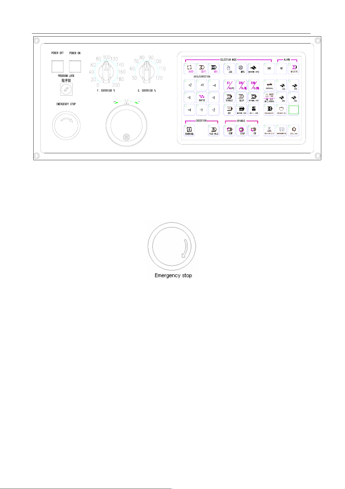
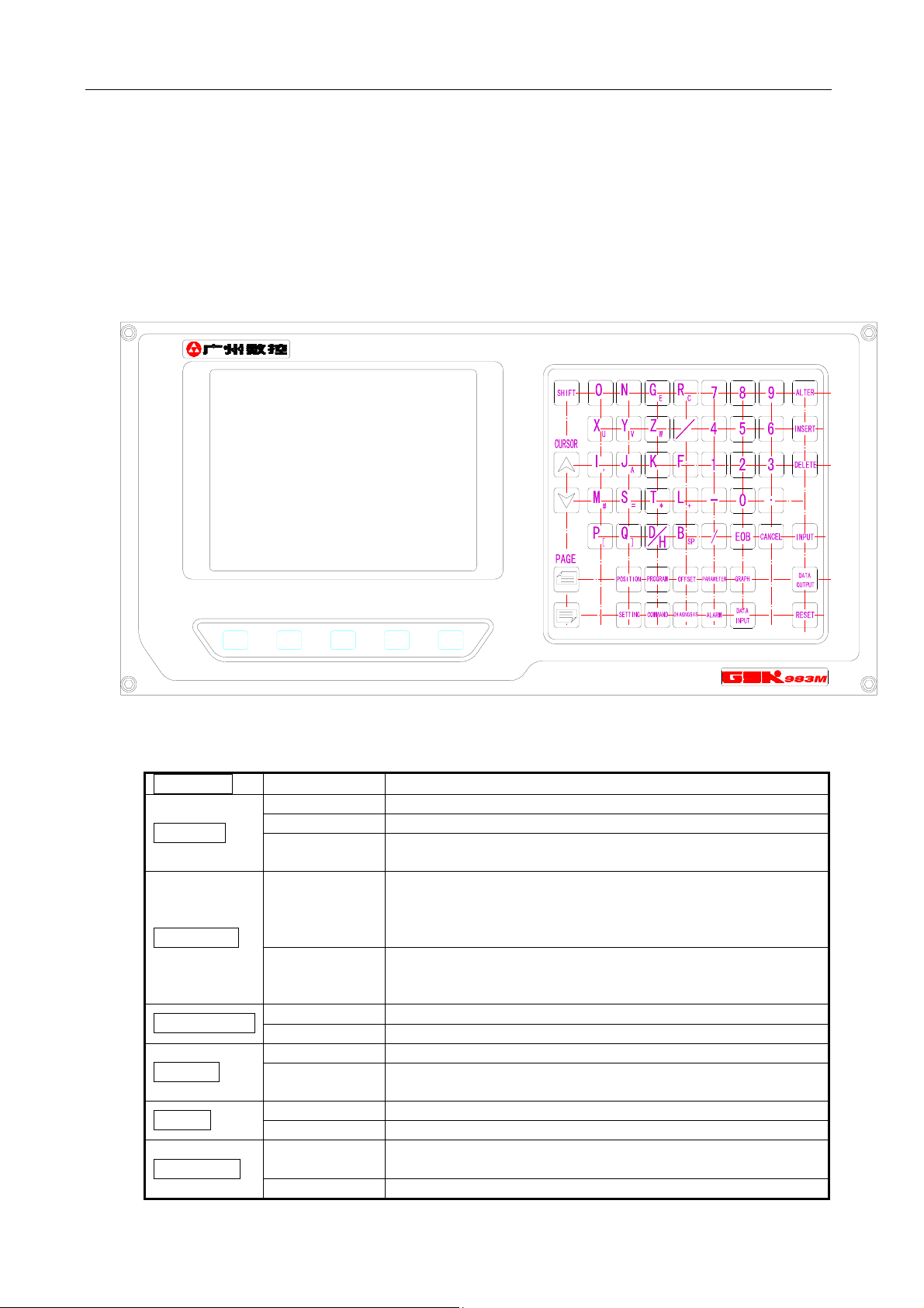
4.3.1 Operation panel
The functions of the operation panel and the layout of switches on it vary depending on different
machine types. The following is a typical operation panel. Refer to the relevant parts of the manual
supplied with the machine for details. This chapter only describes the operation panel of 3-axis
control system (The operation panels of 4-axis and 5-axis control systems are primarily similar to
that of a 3-axis control system).
1
Page 8
GSK983M Milling CNC System Operation Manual (Volume II: Operations)
电源关
电源开
进给倍率 % 主轴倍率 %
急 停
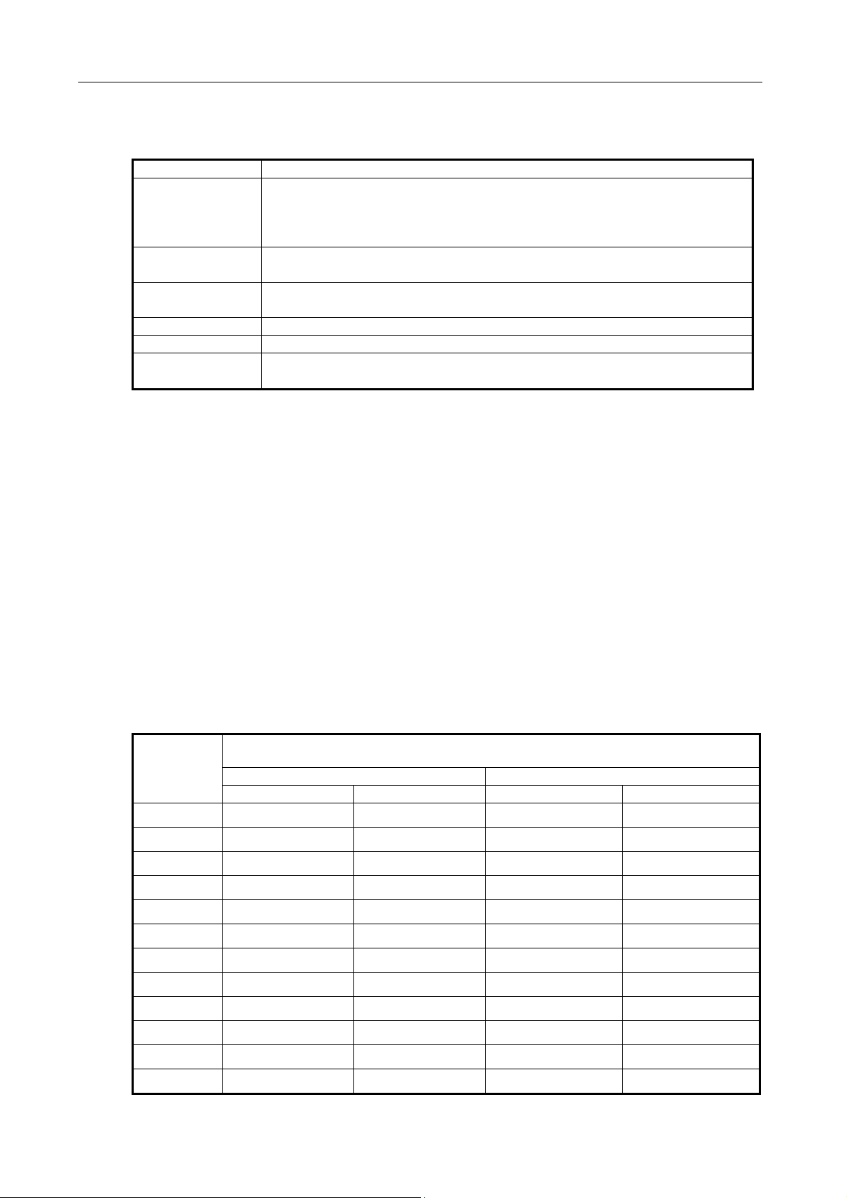
4.3.2 Emergency stop (red)
X
Y
Z 4
In an emergency, press the EMERGENCY STOP button to stop the movements of all the axes of
the machine. At the same time, the button is locked in the stop position.
The release mode of the button varies with different manufacturers. In general, it is released by
pushing down and clockwise turning the button.
Note 1: The power supply of the motor is switched off when the button is pressed.
Note 2: The control unit is in reset state.
Note 3: Make sure to eliminate all troubles before releasing the button.
Note 4: Return to the reference point by through manual operations or G28 instruction.
2
Page 9
GSK983M Milling CNC System Operation Manual (Volume II: Operations)
4.3.3 Selection mode
Modes Functions
EDIT Perform the following operations:
(1) Saving programs in storage;
(2) Modifying, inserting and deleting programs;
(3) Outputting the programs in storage and editing other programs
AUTO
(MEMORY)
MDI (1) Manual data entry may be performed through MDI and the
JOG (1) It is possible to perform Jog feed.
MPG(HANDLE) (1) It is possible to perform manual feed.
MACHINE
ZERO (HOME)
(1) Executing the programs saved in storage;
(2) Search the sequence numbers of the programs in storage
operation panel of the machine.
Return to the machine zero.
4.3.4 Operations involving with manual operation
Except the automatic operations that can be performed with programs, it is possible to conduct
the following manual operations with switches.
4.3.4.1 Jog feed
Jog feed enables the machine to move.
1) Set the selection mode switch to JOG position.
2) Select a motion axis so that the machine travels in the selected direction.
Note 1 2 axes may be concurrently controlled by manual operation.
Note 2 After power on, the selected axis of the machine will not immediately move even the
SELECTION MODE switch is set to JOG position. Now it is necessary to reselect an axis.
3) Selecting Jog feedrate
Position
of switch
0 0 0 0 0
1 1.0 0.04 0.02 0.508
2 1.4 0.055 0.208 0.711
3 2.0 0.079 0.04 1.02
4 2.7 0.106 0.054 1.37
5 3.7 0.146 0.074 1.88
6 5.2 0.205 0.104 2.64
Lead screw for feed in metric system Lead screw for feed in Inch system
mm/min inch/min inch/min mm/min
Feedrate
7 7.2 0.283 0.144 3.66
8 10 0.394 0.2 5.08
9 14 0.551 0.28 7.11
10 20 0.787 0.40 10.2
11 27 1.06 0.54 13.7
3
Page 10
GSK983M Milling CNC System Operation Manual (Volume II: Operations)
12 37 1.46 0.74 18.8
13 52 2.05 1.04 26.4
14 72 2.83 1.44 36.6
15 100 3.94 2.00 50.8
16 140 5.51 2.80 71.1
17 200 7.87 4.00 102
18 270 10.6 5.40 137
19 370 14.6 7.40 188
20 520 20.5 10.40 264
21 720 28.3 14.40 366
22 1000 39.4 20.00 508
23 1400 55.1 28.00 711
24 2000 78.7 40.00 1016
Note 1: The numerical values listed in the above table vary with different machines.
Note 2: The allowable deviation of the feedrates listed in the above table is approximately ±3%.
4) Rapid traverse
An axis rapidly traverses in the selected direction when the button is pressed.
Note 1: The feedrate, time constant and acceleration/deceleration mode for manual rapid traverse are
the same as the rapid traverse under G00 program instruction.
Note 2: When the machine has a memory type travel limit selecting function, it shall be provided with an
axis with the function of returning to the reference point. When the RAPID button is pressed after
power on or emergency stop, its feedrate will not change into rapid feed but maintain at Jog
feedrate provided that the function of returning to the reference point is not executed.
This is because memory type travel limit dose not function before the manual return to the
reference point, thereby preventing the machine from quickly reaching the end of run.
4.3.4.2 MPG feed
Make accurate adjustment for the feed of the machine with a manual impulse generator as
follows.
(1) Set the SELECTION MODE switch to MPG position.
(2) Select a motion axis.
(3) Turn the handwheel of manual impulse generator.
Clockwise…………………..+ direction
Counterclockwise……… - direction
(The rotating direction depends on the settings of manufacturers)
(4) Amount of travel: Some of the operation panels are provided with the following selector
switches: ×10 means multiplying amount of travel by 10 while ×100 by 100.
Input system
×1 ×10 ×100
The amount of travel each step
Input in metric system 0.001mm 0.01mm 0.1mm
Input in inch system 0.0001inch 0.001inch 0.01inch
Note 1: If the handwheel rotates at a speed over 5 turns per second, the amount of the rotation of the
4
Page 11

GSK983M Milling CNC System Operation Manual (Volume II: Operations)
handwheel will differ from the travel distance of the machine. Hence do not rotate the handwheel
too quickly.
Note 2: When ×100 override is selected and the handwheel is turned at quick speed or the workbench
moves at “rapid traverse” rate, the machine will be subject to impact if it is stopped abruptly. The
selection automatic acceleration/deceleration function is also valid for manual feed, thereby
reducing mechanical shock.
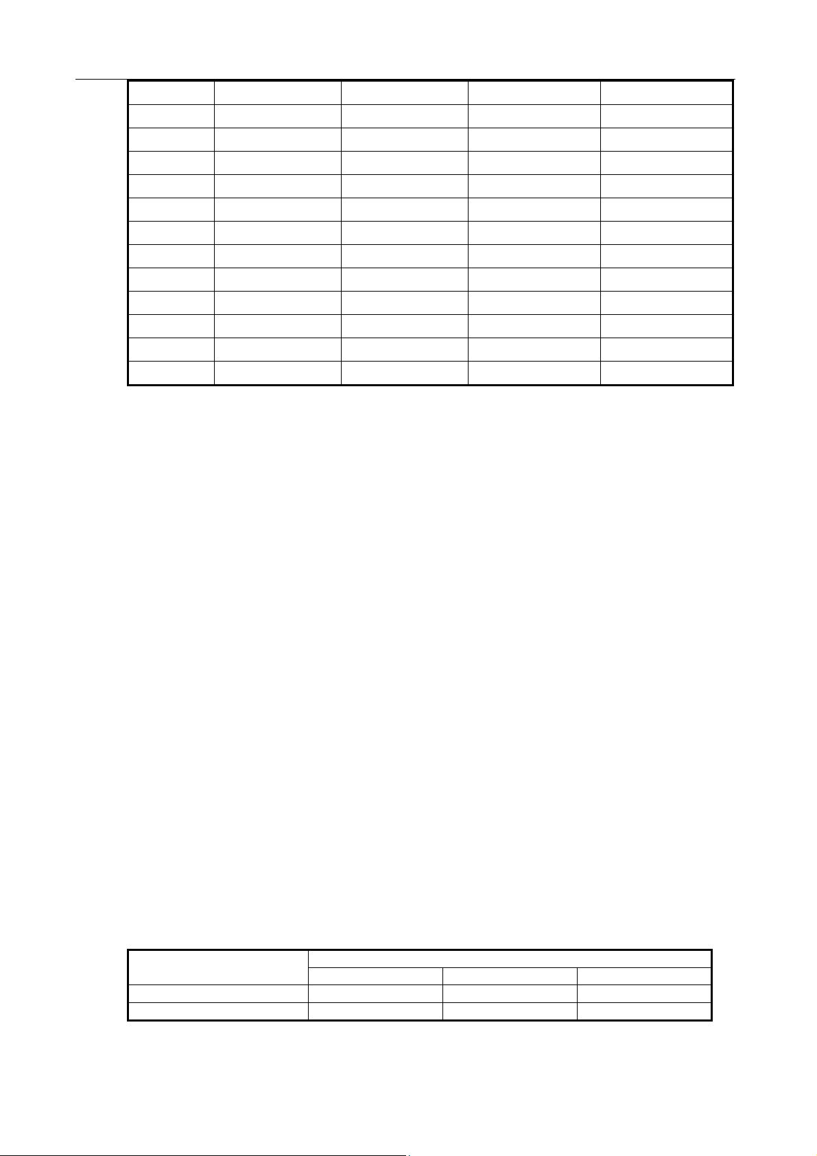
4.3.4.3 Manual absolute
If the switch is set to ON, the manual-operated travel amount will be added to the coordinate axes.
(1) MANUAL ABSOLUTE switch ON: Coordinates change with manual operation.
(2) MANUAL ABSOLUTE switch OFF: Coordinates do not change.
(Example) For example, in the following blocks:
…
G01 G90 X100.0 Y100.0 F010;①
X200.0 Y150.0 ;②
X300.0 Y200.0 ;③
…
a) The above block has been executed while block is only executed after manual ①②
operation (travel by 20.0 in X direction and 100.0 in Y direction).
5
Page 12
GSK983M Milling CNC System Operation Manual (Volume II: Operations)
b) Press the FEED HOLD button in the execution of the block . After manual operation ②
(Y+75.0), press the CYCLE START button so as to cancel the hold mode and continue the
execution.
c) Press the FEED HOLD button in the execution of the block . Reset the machine after ②
manual operation (Y+75.0). The block restarts inputting. ②
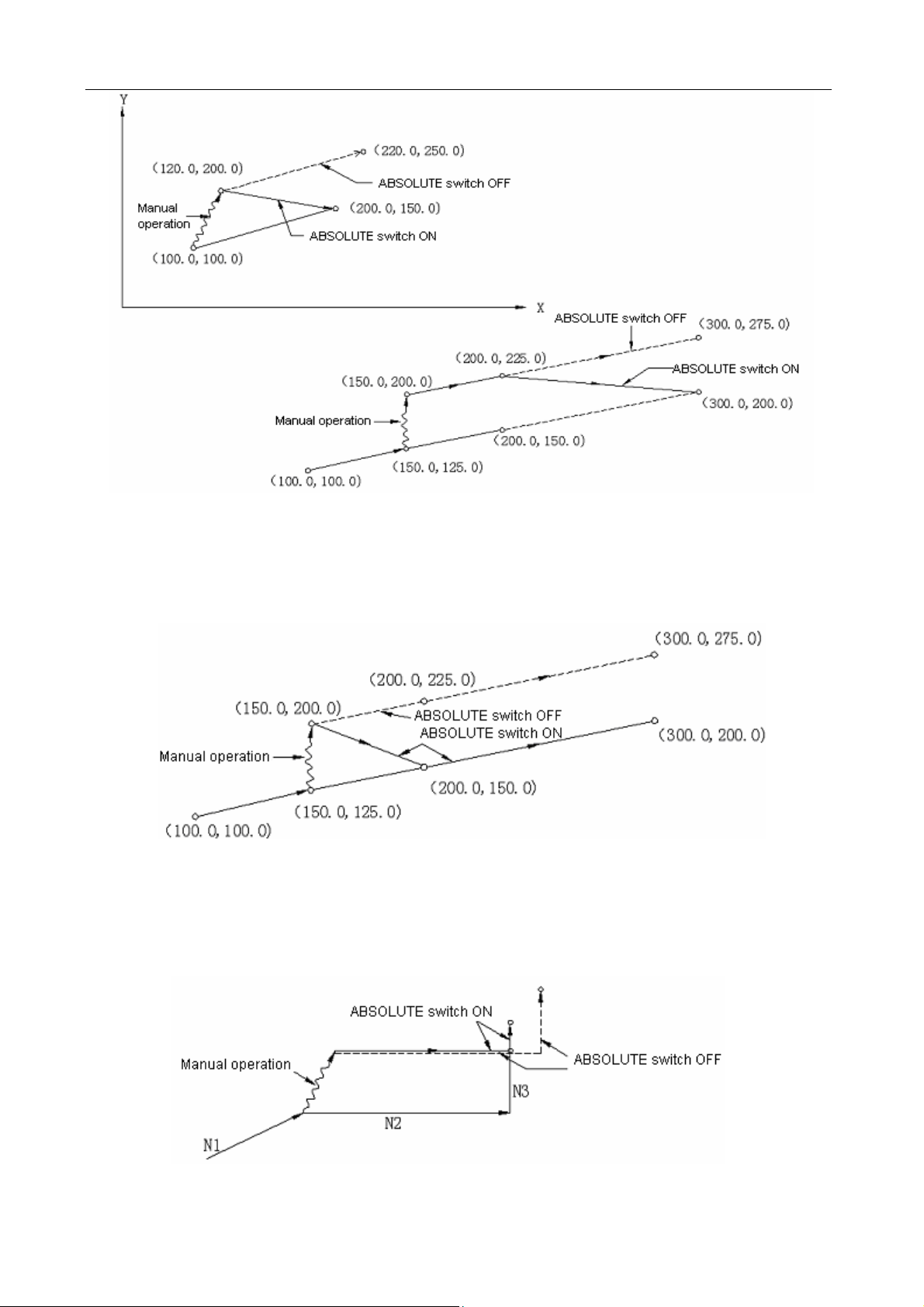
d) When manual operation is followed by a single-axis instruction, then only the instructed axis
returns to the programmed absolute position of the axis.
N1 G01 G90 X100.0 Y100.0 F5000;
N2 X200.0;
N3 Y160.0;
e) When manual operation is followed by an incremental instruction, then the position that the
6
Page 13
GSK983M Milling CNC System Operation Manual (Volume II: Operations)
axis moves to is identical with that is instructed while the MANUAL ABSOLUTE switch is set
to OFF.
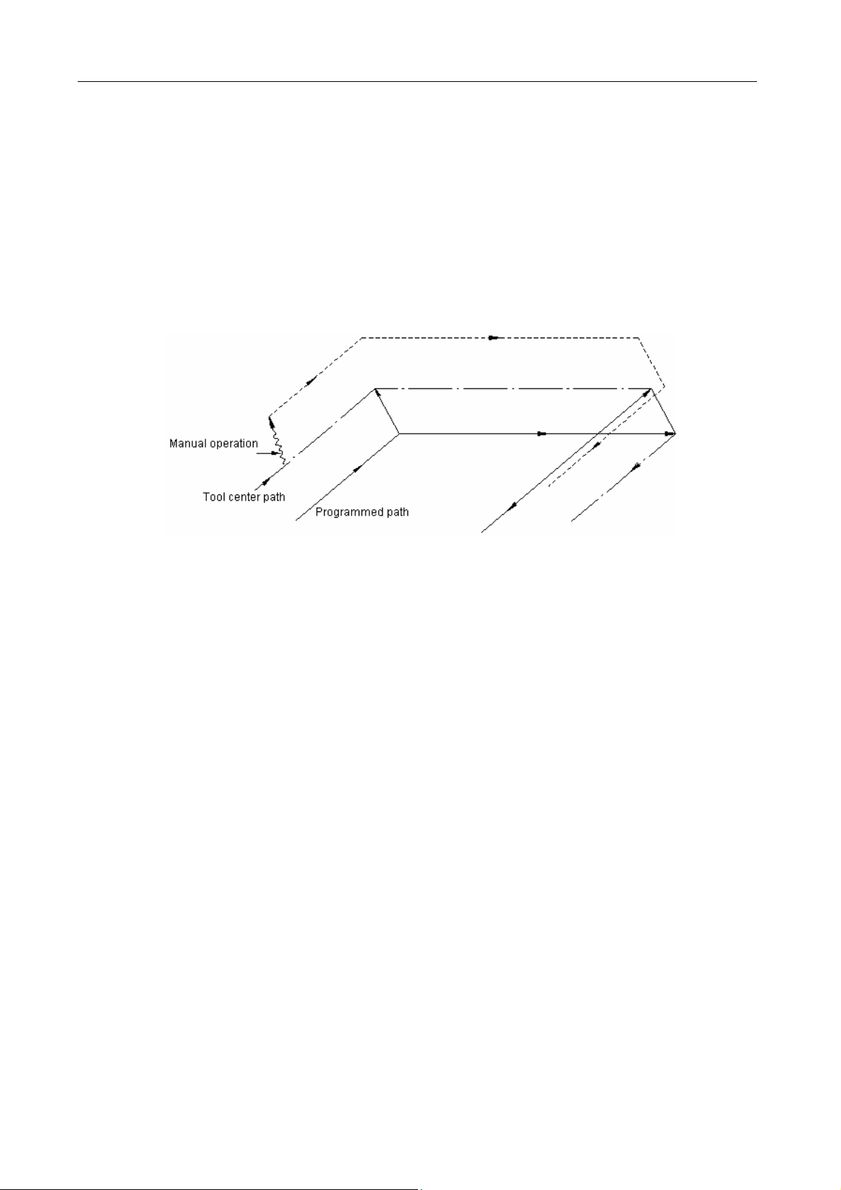
Note 1: Insert manual operations when tool radius compensation C offsets. Now the actual motion path
of the tool is as follows:
(1) MANUAL ABSOLUTE switch OFF
When tool radius compensation C is enabled:If MANUAL ABSOLUTE switch is switched off for
manual operation when tool radius compensation C is enabled, the path of the automatic tool
motion will translate in parallel by the offset of the inserted manual operation.
(2) MANUAL ABSOLUTE switch ON
When tool radius compensation C is enabled:If MANUAL ABSOLUTE switch is switched on for
manual operation when tool radius compensation C is enabled, the path of the tool under
absolute instruction after restart is as follows. The tool path for the blocks after manual operation
runs parallel to the vectors of the origin of the next block.
Tool path is determined by the vectors between the next block and the block that follow. For the angle
machining with the intervention of manual operation, its tool path is identical with the above.
If a program consists of incremental instructions rather than absolute instructions, its tool path is
identical with that when the MANUAL ABSOLUTE switch is set to OFF.
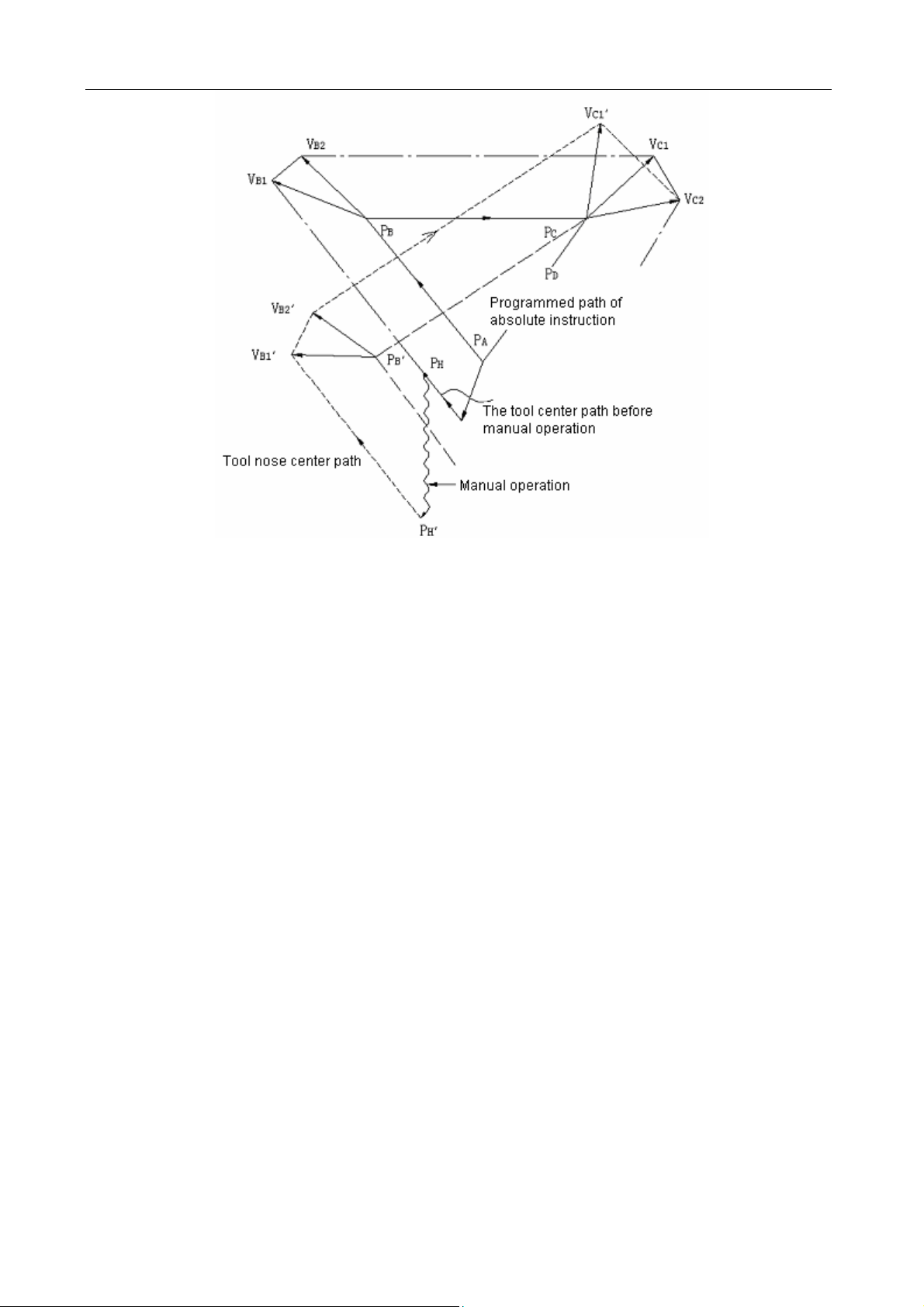
(a) Performing manual operations during execution of a block
Example 1: In the following programmed path (PA→PB→PC→PD), assuming the point PH
between PA and PB is moved to point PH′ by manual operation after pressing the FEED
HOLD button, the end point PB of the current block translates to point PB’ due to the offset
as a result of manual operation and the vectors VB1 and VB2 of the original point PB also
translate to V’B1 and V’B2.
7
Page 14
GSK983M Milling CNC System Operation Manual (Volume II: Operations)
The vectors between the next block (tool path from PB to PC) and the one that follows (from
PC to PD) do not need compensation. The new vectors (VC1′, VC2′) with compensation
results from the relationship between the two blocks (programmed paths from PB′ and PC to
PD and from PC to PD). Since vector VB2′ coincides with VB2, however, the section of path
between PB’ and PC as a result of tool offset is not accurately performed. But for the block
after point PC, tool offset can be precisely performed.
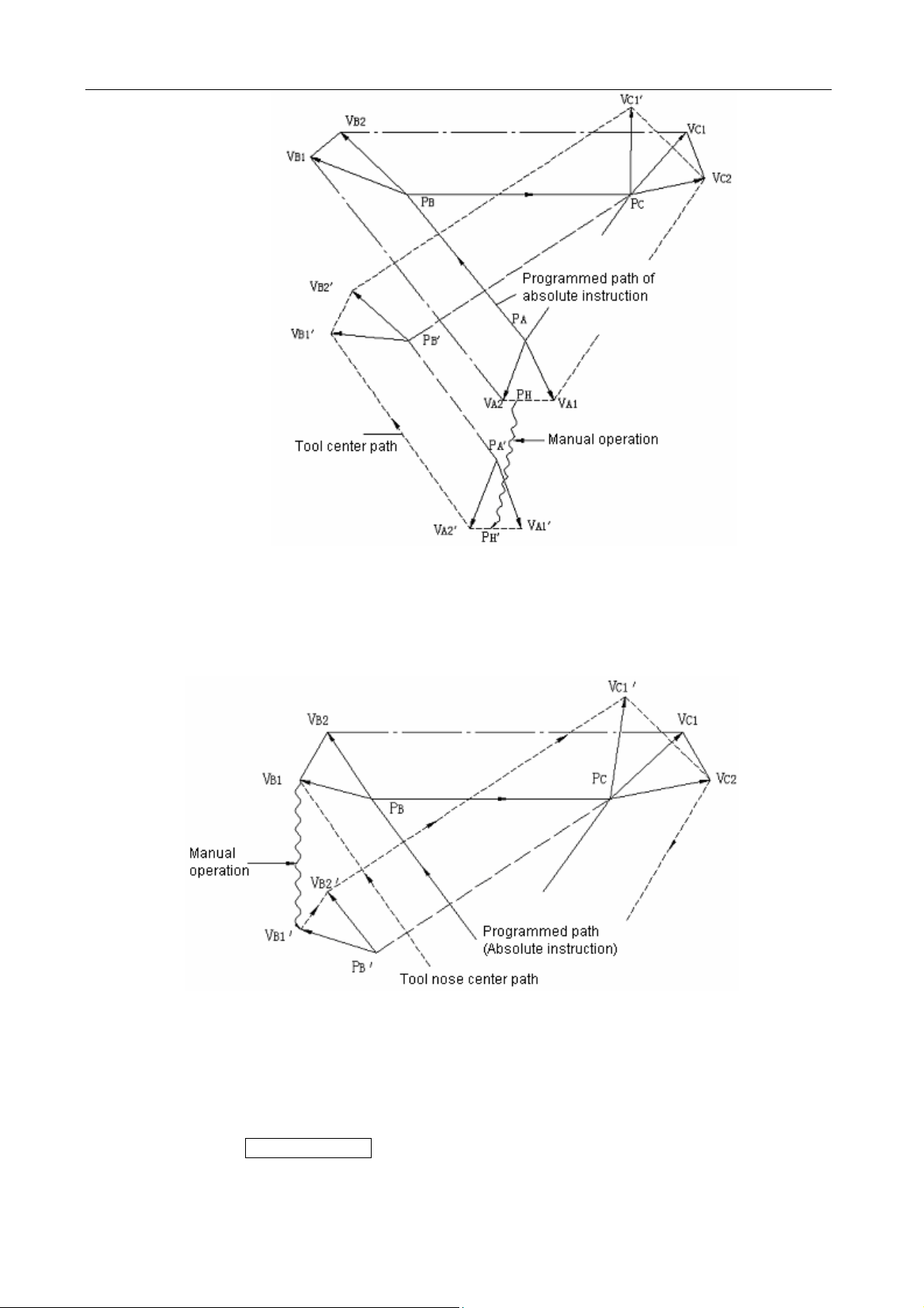
Example 2: If manual operation is inserted in angle machining in the case of tool radius
compensation, the feed path after manual operation will be determined by the same method
as Example 1. That is, the vectors VA2′, VB1′ and VB2′ in the figure below are determined by
translating the vectors VA2, VB1 and VB2 by an amount of manual travel and the new
vectors result from V
′ and VC2′. The block after point PC will be precisely performed by the
C1
tool offset compensation C.
8
Page 15
GSK983M Milling CNC System Operation Manual (Volume II: Operations)
(b) If manual operation is inserted after the execution of single block function, the vectors VB1
and VB2 for the end points of the current block will be moved in parallel and the method for
determining the following feed path will be identical with (a). MDI operation may be inserted
after the execution of a block with single block function. The feed path after MDI operation
coincides with tat after the insertion of a manual operation.
4.3.5 Manually returning to reference point (reference position)
The machine may return to the reference point by manual operations:
1) Set the SELECTION MODE to JOG.
2) Press the MACHINE ZERO key.
3) Move all axes toward the reference point by Jog feed.
The machine rapidly traverses to the deceleration point and then to the reference point at FL
9
Page 16

GSK983M Milling CNC System Operation Manual (Volume II: Operations)
speed. Rapid traverse override is still active during traversing.
4) The machine stops at the reference point and the indicator indicating the end of the return to
the reference point is lit.
Note 1: The indicator is lit after the return to the reference point. If the switch for returning to the
reference point is set to ON position, the machine cannot translate in Jog mode.
Note 2: The following procedures may extinguish the indicator: (1) Move the machine away from the
reference point; (2) Press the EMERGENCY STOP button.
Note 3: For the distance to the reference point, refer to the manual supplied by the manufacturer of the
machine.
4.3.6 Operations on automatic running
The machine may automatically run by programs.
4.3.6.1 Start of automatic operation
Procedures for starting the program stored in memory:
(a) Select the program number. See Section 4.4.16 “Program number search”.
(b) Select AUTO mode.
(c) Press the CYCLE START button. Automatic operation starts once the CYCLE START
button is pressed and at the same time the CYCLE START indicator is lit.
Note 1: The programs read in are loaded when the CYCLE START button is pressed in EDIT mode. The
loading mode is the same as that when the INPUT button is pressed for parameter setting.
Note 2: The CYCLE START button is inactive in the following conditions:
(a) When the FEED HOLD button is pressed;
(b) When the EMERGENCY STOP button is pressed;
(c) When the RESET signal is enabled (contact the manufacturer of the machine for details);
(d) When the SELECTION MODE switch is set to a wrong position (other than AUTO or EDIT
mode);
(e) When it is search a sequence number;
(f) When an alarm is given;
(g) When automatic operation is selected;
(h) When the NC system is not ready
4.3.6.2 Suspension of automatic operation
Press the FEED HOLD button
The FEED HOLD indicator illuminates and the CYCLE START indicator goes out when the
FEED HOLD button is pressed. And now,
(a) If the machine is moving, the feed slows down and stops;
(b) If the machine is in hold state, the hold state will interrupt even in FEED HOLD mode;
(c) The machine stops after the performance of M, S, T or B function.
4.3.6.3 Single block
If the SINGLE switch is turned to ON position, the control only executes a block each time and
10
Page 17
GSK983M Milling CNC System Operation Manual (Volume II: Operations)
stops when the CYCLE START button is pressed.
The control only executes a block each time and stops when the SINGLE switch is turned on.
When the CYCLE START button is pressed, the control stops after the execution of the next
block.
Note 1: In G28, G29 or G30 mode, the tool stops at the intermediate point if the SINGLE function is used.
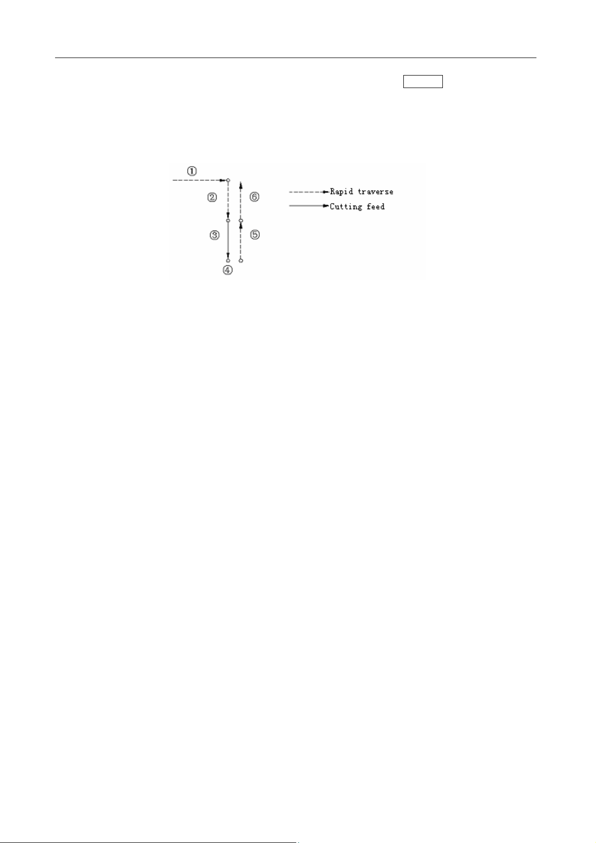
Note 2: For fixed circular processing, the tool stops at the end point of the circular path ①, or of the ②⑥
fixed cycle (see the figure below) if the SINGLE function is active.
When the result of the fixed circular calculation is not 1, the FEED HOLD indicator illuminates
except the block of the final cycle. The FEED HOLD indicator illuminates whenever block ⑥ ①
or stops.②
Note 3: For the blocks of M98P—, M99 and G65, G66 or G67, the stop of the single block is invalid.
However, it is valid if the instructions in M98 or M99 block are of the addresses other than O, N, L
and P.
4.3.6.4 Restart after feed hold or stop
(1) Select the AUTO mode;
(2) Press the CYCLE START button. The FEED HOLD indicator goes out when the CYCLE
START button is pressed.
4.3.6.5 The manual operations in automatic run
(1) In automatic run, suspend the operation by pressing the FEED HOLD button on the
operation panel or bring the SINGLE switch to ON position.
(2) Record the coordinates of the stop position displayed by the location display unit.
(3) Perform JOG operation (see Section 4.3.4.3).
(4) Return the tool to the recorded coordinates (the origin of JOG operation).
(5) Set the SELECTION MODE switch to the position before JOG operation so as to restart
automatic run.
(6) Press the CYCLE START button.
4.3.6.6 The MDI operations in automatic run
(1) Set the SINGLE switch to ON position.
(2) Select MDI operation mode.
(3) Perform MDI operation.
(4) To restart automatic operation, return to the original operation mode and press the CYCLE
START button on the operation panel.
Note 1: The modal data reserved in cycle movement is under influence when MDI instruction is used.
Note 2: The modal data instructed by MDI is still valid for automatic MDI operation.
11
Page 18

GSK983M Milling CNC System Operation Manual (Volume II: Operations)
Note 3: Too radius compensation C is not performed during MDI operation.
Note 4: MDI operation is disabled in feed hold state.
4.3.6.7 Skipping over optional blocks
When some block contains “/n”(n=1 to 9), the function allows the control to skip over the block.
Switches correspond to the 19 numbers respectively.
Note: While blocks are being read in the buffer from storage, the validity of function of skipping
over optional blocks is judged. Therefore the function is invalid for the blocks read in buffer
register.
4.3.6.8 Feedrate override
For the feedrate set by F function, it is possible to set an override in the range of 10% to 200%.
An override of 10% increment is recommended.
4.3.6.9 Dry run
If the switch is set to ON position in the cycle operation instructed by storage or MDI, the F
function does not work and the machine travels at the following speeds.
RAPID button ON/OFF In rapid traverse In cutting feed
RAPID button ON Rapid traverse Maximum Jog feedrate
RAPID button OFF Jog feedrate (see Note) Jog feedrate
Note: The dry run of rapid traverse may be disabled or enabled by parameter setting.
4.3.6.10 Machine lock
When the MACHINE LOCK switch is set to ON, the movement instruction pulse is inhibited.
Therefore the position indication for circular feed start or JOG operation is continuously
updated according to input instructions. But the machine does not move itself. The function is
used to check procedures.
Note 1: When G27, G28 or G30 instruction is set, the machine will not return to the reference point.
Hence the indicator for returning to the reference point is not lit.
Note 2: M, S, T and B functions are performed.
4.3.6.11 Display lock
When the DISPLAY LOCK switch is activated, the coordinates indicated by the location display
unit are locked. For instance, when the coordinate system is moved as a result of JOG
operation, the use of this switch prevents the indicated values from changing by manual
movement.
Note: The function is optional.
4.3.6.12 Mirror image
Once the mirror image switches of axes X and Y as well as the 4th axis are activated in
automatic operation, the axes move reversely. The reference point is returned to by JOG or
automatic operation, the movement between the intermediate point and the reference point
does not inverse and position display depends on the actual movement of the tool. This may
be achieved by setting parameters with MDI unit (see Section 4.4.7).
12
Page 19

GSK983M Milling CNC System Operation Manual (Volume II: Operations)
4.3.6.13 Rapid traverse override
It is possible to set the rapid traverse override switch of optional overrides 100%, 50%, 20%
and F0 on the operation panel of the machine.
When the feed speed is 10m/min and the switch is set to 50% position, the actual feed speed
will be 5m/min.
F0 is a fixed speed (feedrate) provided by the manufacturer of the machine. The function
applies to the following conditions:
(1) The rapid traverse specified by G00;
(2) The rapid traverse in fixed cycles;
(3) The rapid traverse in G27, G28, G29 and G30 modes;
(4) JOG rapid traverse;
(5) The rapid traverse for manually returning to the reference point.
4.3.6.14 External workpiece number search function
Select a workpiece number to be processed with the switch on the operation panel of the
machine (No example of the operation panel is given in this user manual). (Machining
programs are pre-stored in the part program storage.) Press the START button. Now the
system automatically executes the program corresponding to the workpiece number. By using
the function, operator does not need to search the stored program numbers so as to reduce
dry run time and errors.
(1) Preparation for the program: In the situations using the function, the numbers assigned to
programs shall correspond to the workpieces to be processed. That is, a number among
01 to 31 shall be designated for each workpiece to be processed. The relevant program
number is expressed as follows:
0(:) 0 0
They are stored in the part program memory. As shown in the following examples, each
program shall be started by the address 0 followed by a program number and ended by
M02, M30 or M99.
In addition, the storage of the programs irrespective of workpiece number is allowable.
0 0001;
N 0001 G00…; The program corresponding to workpiece No. 01
……………………
……………………
N 120 M02;
0 0002;
N 0001 G00…; The program corresponding to workpiece No. 02
……………………
……………………
N 300 M30;
0 0004;
N 001 G00………
………………………
………………………
□ □ (0 for EIA and : for ISO)
Workpiece number (01 to 31)
Optional workpiece number
The program corresponding to workpiece No. 04
13
Page 20

GSK983M Milling CNC System Operation Manual (Volume II: Operations)
N 080 M02;
0 6247;
N 001 G00………
……………………… Programs irrespective of workpiece number
………………………
N 034 M99;
Note 1: Each program shall be started by the address 0 followed by a program number and ended by
M02, M30 or M99. However, M02, M30 and M99 cannot be specified in the middle of the
program. If one of them is specified in the middle section, the program that follows will
regarded as another program segment (the block following M02, M30 or M99 is immediately
numbered as a program when the program is stored in memory).
Note 2: The allowable quantity of workpiece numbers depends on factory setting (see the manual of
the machine).
Note 3: For the machine system provided with external workpiece number search function A, the
allowable maximum workpiece number is 31. Now the first two digits of the program number
corresponding to a workpiece number must be 00.
(1) Operating procedures
Operating procedures vary with different manufacturers of machine. The operating
procedures described below are general. Refer to the manual supplied by manufacturer of
the machine for specific operating procedures.
Note 1: Select the automatic mode and then set the program (01 to 31) corresponding to the workpiece
number with the rotary switch on the operation panel on the machine side. When the START
button is pressed, the program corresponding to the set workpiece number will be searched
out and machining performed with the start of the program.
Note 2: When a workpiece number is set to 00, the corresponding program will not be searched if the
START button is pressed. The execution starts from executable section of the current program.
For the situations that starts in the midway of the program or that the executing program is
independent of workpiece number, it is necessary to set the workpiece number to 00 and press
the START button after sequence number search or program number search.
Note 3: The function does not apply to MDI operation but automatic operation.
Note 4: If a program number corresponding to the workpiece number is not stored in the memory, an
alarm (No. 59) will be given once the START button is pressed.
Note 5: It is not always necessary to select the relevant program even a workpiece number is selected
with the dial. Refer to the manual supplied with the machine for the procedures for selecting a
program. When workpiece number search function A is selected, program search is performed
after the NC system starts automatic operation in reset mode.
4.3.7 JOG feed at any angle
Set an angle and feedrate in the plane of X and Y and then press the START button. In this
way the machine may feed at any set angle by JOG operation.
(1) Set the SELECTION MODE switch to the mode of JOG feed at any angle
(2) Set an angle with the angle setting dial. The position of an angle is selected among 0-71 with a
2-digit BCD code. 0 ~71 correspond to 0 ~360° respectively (in 5° increment).
14
Page 21

GSK983M Milling CNC System Operation Manual (Volume II: Operations)
For angle setting, make sure to switch on angle strobe pulse. If angle strobe pulse is switched
on, the formerly set angle will remain valid.
As shown in the above figure, the + direction of Axis X is 0° and that of Axis Y is 90°.
(3) Select a feedrate (speed in tangential direction) with the Jog feed dial.
(4) Press the START button in the mode of JOG feed at any angle. Then the machine moves at
the selected feedrate in the set direction.
If the JOG RAPID button is pressed, the machine will feed at the maximum Jog feedrate. The
machine feeds when the JOG RAPID TRAVERSE button is switched off and stops feed when
it is switched off.
Note 1: If axes X and Y are interlocked, both axes will slow down and stop. They will restart once the
interlocking is disabled.
Note 2: In automatic operation, it is possible to insert JOG feed at any angle when the machine is stop
in feed hold mode.
Note 3: For the situation with external deceleration selection, JOG feed at any angle is also active.
Now the tangential feed is equal to the external decelerating rate.
Note 4: The automatic acceleration and deceleration for cutting feed also apply to the JOG feed at any
angle.
Note 5: JOG feedrate at any angle does not change with Jog feedrate even during the switching
between metric and inch systems.
4.3.8 Manual insertion
For the specific axis (fixed by parameter) in automatic operation, the movements operated with
handwheel may be performed in addition to the self-motion of the axis.
4.3.8.1 Inserting operations by MPG(manual pulse generator/handwheel)
Manual insertion is possible by turning the manual pulse generator in the following conditions.
(1) Mode: automatic mode or MDI mode
(2) Operating state: Manual insertion is possible during linear interpolation, arc interpolation, spiral
interpolation or sine-curve interpolation.
However, the following conditions are excluded:
(I) When an alarm is given;
(II) When any axis does not move;
(III) When positioning is valid;
(IV) When interlocking is active;
(V) In the absence of travel instruction.
15
Page 22
GSK983M Milling CNC System Operation Manual (Volume II: Operations)
(3) Manual axis selection signal
Manual axis selection signals (HX, HY, HZ, H4 and H5) are switched on (contacts close) for the
axes to perform manual insertion.
4.3.8.2 Manual inserting movement by MPG
(1) Amount of travel: The amount of travel to be inserted by manual shall be identical with that
during JOG feed. The amount of travel depends on the scale of the manual pulse generator and
JOG feed overrides (X1, X10 and X100) and is added to that of automatic operation.
(2) Traverse speed: The axial speed for JOG insertion is the result of the addition of the travel speed
of automatic operation to that inserted by manual. Therefore, axial speed is limited to rapid
traverse speed (Parameter HR) in the event that axial speed exceeds rapid traverse speed.
Displacement mismatches the indicated value of the manual pulse generator.
(3) The correspondence between manual-inserted travel and all signals is as follows:
Signal Travel
Machine is
locked
Display is
locked.
Mirror image of
Axis X
(4) The correspondence between manual-inserted travel and position indications is as follows:
Affected: The tool does not move when MACHINE LOCK is enabled.
Affected: Relative coordinates remain unchanged when display is locked.
Not affected: The machine moves forward when the handwheel is turned
clockwise.
Indication Travel
Absolute
coordinates
Relative
coordinates
Mechanical
coordinates
Not affected: Manual-inserted pulse is not added to absolute coordinates
Affected: Manual-inserted pulse is added to relative coordinates
Affected: Manual-inserted pulse is not added to mechanical coordinates
(5) Indication of amount of travel: Manual-inserted amount of travel may be displayed in diagnosis
message (Diagnosis No. 805 to 809). To display a diagnosis message, press the function key
DIAGNOSIS on the MDI panel.
Diagnosis data numbering
8 0 5 Manual-inserted amount of travel of Axis X
8 0 6 Manual-inserted amount of travel of Axis Y
8 0 7 Manual-inserted amount of travel of Axis Z
8 0 8 Manual-inserted amount of travel of the 4th axis
8 0 9 Manual-inserted amount of travel of the 5th axis
Unit: 0.001mm (input in metric system)
0.0001 inch (input in inch system)
Note: Only the removable amounts of travel are cleared.
16
Page 23
GSK983M Milling CNC System Operation Manual (Volume II: Operations)
4.4 The Display and Operations of the MDI/LCD Panel with LCD
Characters
The MDI/LCD panel is usually mounted on the upper front side of the control cabinet. It consists
of an LCD and buttons as follows.
Function buttons: The large number of items displayed with the function buttons is just like the
chapters of a book. When a function button is pressed for the second time and third time, the chapter
2 or 3 of the corresponding display functions (if the function button for the chapter is provided). Each
chapter includes several pages and each page is selected with the page button.
4TH
5TH
The names and meanings of all function buttons are listed below.
POSITION
Pressing once Display of actual position and reset
Pressing once Display and setting of set data
SETTING
Pressing twice Display and setting of user macro variables
Pressing for
the third time
Display and setting JOG switch
Display of the information regarding a program in EDIT
Pressing once
PROGRAM
mode
Display of the executing or executed blocks and the blocks
that follow in a mode other than EDIT
Display of the list of program numbers (See Section
Pressing twice
4.4.24.12) (The chapter 2 may also be omitted depending
on the conditions of the system.)
PARAMETER
Pressing once Display and setting of parameters
Pressing twice Display and setting of PC parameters
Pressing once Display and setting of offset
OFFSET
ALARM
COMMAND
Pressing twice
Pressing once Display of the information of an alarm
Pressing twice Display of an external alarm and external information
Pressing once
Display and setting of origin offset in a workpiece
coordinate system
Display of instruction value and the instructions input
through MDI
Pressing twice Display of the information regarding program restart
17
Page 24
GSK983M Milling CNC System Operation Manual (Volume II: Operations)
DIAGNOSIS
Note: Clear the displayed screen by concurrently pressing a function key and CANCEL button.
The corresponding screen is displayed when the function button is pressed again.
4.4.1 Status display
The status indication of the system is displayed on the lower right part of the screen:
Pressing once Display of system diagnostic data
Pressing twice Display of the information regarding tool life management
Status indication
The displayed indications are as follows:
NOT READY indicates that the control or servo system fails to operate. LSK indicate the LABEL
SKIP mode created after power on or reset of control rather than in MDI mode. BUF indicates
that a block is read in but not executed. The block not executed still does not disappear after
reset in rather than MDI mode. ABS indicates that MDI instruction is absolute and INC state will
be entered into when the SHIFT button is pressed. INC indicates that MDI instruction is
incremental ABS state will be entered into when the SHIFT button is pressed. ALM indicates that
an alarm is given. The alarm type will be displayed (the symbol blinks) when the ALARM button
is pressed. EDIT indicates that the editing function is being executed (the symbol blinks). The
stopping operation of edition shall be performed when the symbol exits. SRCH indicates that
sequence search is being performed (the symbol blinks). RESTR indicates that the period from
program restart to the return to the final axis (the symbol blinks).
4.4.2 Key input
The entries input with address keys or numerical keys are displayed at the bottom of the screen.
18
Page 25
GSK983M Milling CNC System Operation Manual (Volume II: Operations)
Data cannot be typed in any more when the POSITION or and ALARM button among the
function buttons is pressed to display a screen.
Press D/H to enter D and again to enter H.
Only a word consisting of one address and a figure can be typed in when Program edit is not
being performed. Pressing CANCEL once clear a word.
One or more words, a block or any character string of up to 32 characters can be entered with
the keys during Program edit.
The last entered character is cleared by pressing the CANCEL key. If the CANCEL key is
pressed continuously, the typed characters will be cleared in succession.
Note: In EDIT mode, Program edit is possible when the PROGRAM button is pressed.
4.4.3 Display of program numbers and sequence numbers
Program numbers and sequence numbers are displayed at the top of the screen as shown in the
following picture.
19
Page 26
GSK983M Milling CNC System Operation Manual (Volume II: Operations)
The meanings of the displayed sequence numbers and program numbers are as follows:
Mode Operation Indication
Mode other than
EDIT
Auto mode
(MEMORY)
Edit mode
Auto mode
(MEMORY)
In the mode other than EDIT
When search a sequence
number
Pressing the cursor ↑ key
when the function button is
in PROGRAM mode
Pressing the cursor ↓ key
when the function button is
in PRG mode
Pressing the cursor ↑ key
when the function button is
in PRG mode
Entering reset state by
pressing the RESET button
Program number search
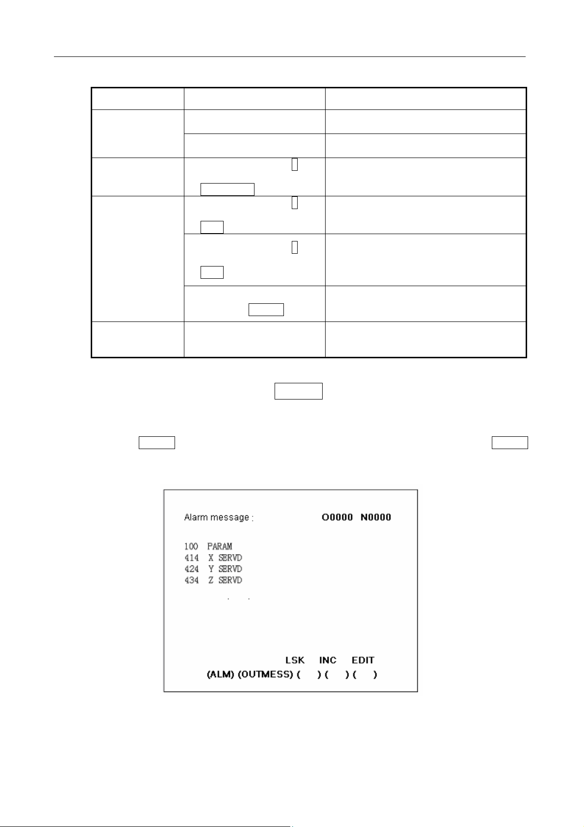
4.4.4 Alarm display (function button ALARM)
To display the last displayed sequence
number
To always display the sequence number
during search
To return to the start of a block
To display the block
To review programs in + direction from the
actual position of the storage;
To display the firstly found N value
To review programs in - direction from the
actual position of the storage;
To display the firstly found N value
To return to the switch of the block and
display the block
To display the program numbers
searched
When ALM is indicated at right bottom of the screen in case of alarm, clear warning messages
through the following procedures
Press the ALARM button. When the information about operator is displayed, press the ALARM
button again to display alarm message.
Refer to Appendix 6 for the meanings of all alarm numbers
Note: As a rule, alarm message appear on the screen in the event of alarm.
20
Page 27
GSK983M Milling CNC System Operation Manual (Volume II: Operations)
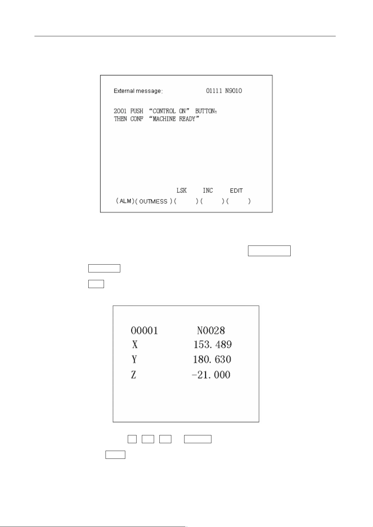
4.4.5 Operator information
Once the machine sends out operator information, the information will be automatically
displayed on the screen.
When operator information appears after some other page is displayed, press the ALARM button.
When alarm message appears, press it again.
4.4.6 Display of actual position and reset (function key POSITION)
(1) Press the POSITION button.
(2) Press the Page button. Data is displayed in one of the following three modes.
(I) Position display in a relative coordinate system
Relative position is displayed once operator resets a position to zero.
Reset: When the X , Y , Z or 4TH/5TH button is pressed, the pressed address
characters will continuously blink. The relative position of the blinking address will be set for
0 when the SHIFT button is pressed again.
(II) Position display in a workpiece coordinate system
The current value of program coordinate system is set by G92, automatic coordinate system
or reset and displayed. For Axis T, the currently selected tool number is displayed. Reset
21
Page 28
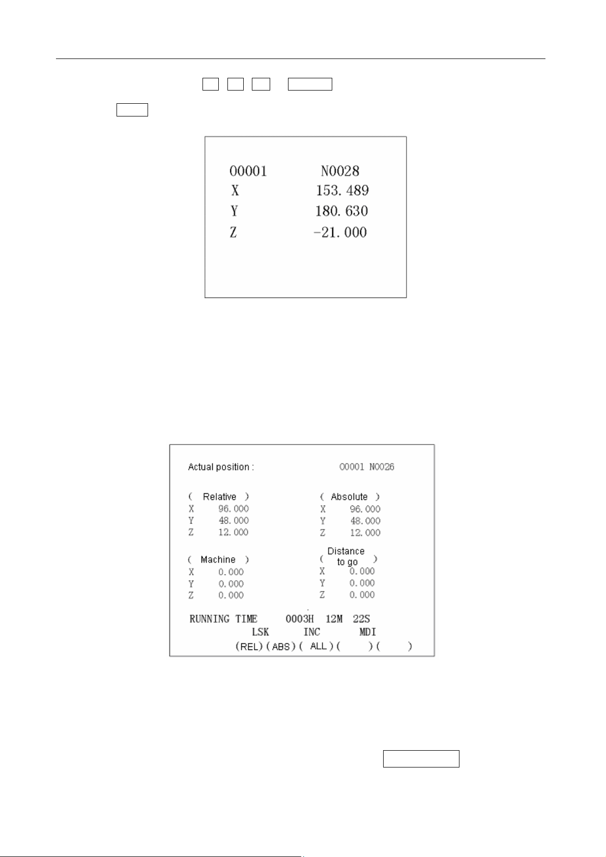
GSK983M Milling CNC System Operation Manual (Volume II: Operations)
(program protection unlocking)
For resetting, the X , Y , Z or 4TH/5TH button is pressed. The pressed address
characters will continuously blink. The coordinate position of the blinking address when the
SHIFT button is pressed again. The actual position of the blinking address is reset.
Note: Reset operation can only be performed in automatic stop status.
(III) Display of comprehensive position
The actual position is displayed in the following coordinate systems at the same time:
(a) The position in relative coordinate system (RELATIVE)
(b) The position in absolute coordinate system (ABSOLUTE)
(c) The position in machine coordinate system (MACHINE)
(d) The distance to be traveled (DISTANCE TO GO)
DISTANCE TO GO indicates the remaining distance of a block. The positions of all coordinate
systems cannot be reset when displaying the comprehensive position. The unit of machine
coordinate system is identical with that of the machine system.
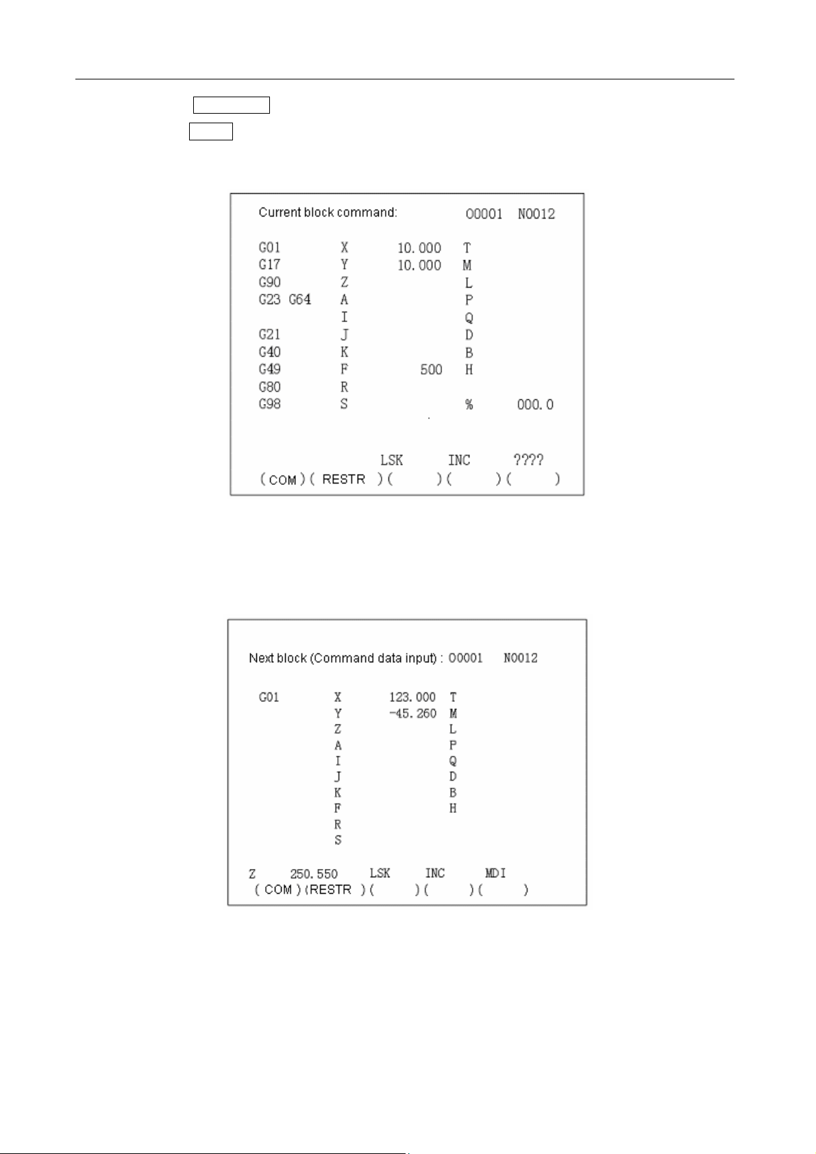
4.4.7 Indication of instruction value (function button COMMAND)
22
Page 29
GSK983M Milling CNC System Operation Manual (Volume II: Operations)
(1) Press the COMMAND button.
(2) Press the PAGE button. Data is displayed in the following two modes.
(I) Display the formerly set modal values while executing an instruction value.
As shown in the above figure, the figure following character % stands for feedrate.
(II) Display the instruction value input by MDI or the instruction value to be executed next time.
(III) Display the instruction value of the next block to be executed during the tool offset of tool
radius compensation C.
23
Page 30
GSK983M Milling CNC System Operation Manual (Volume II: Operations)
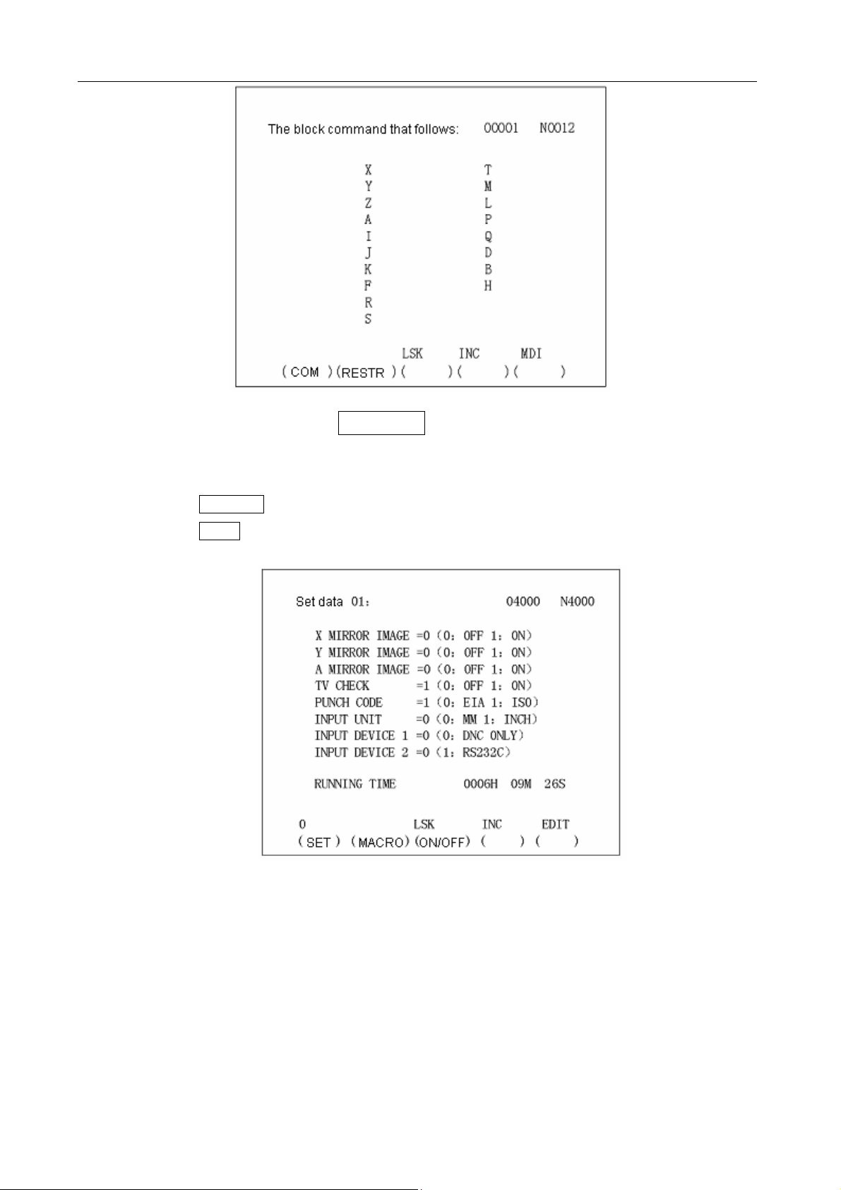
4.4.8 Setting (function button SETTING)
4.4.8.1 Display and setting of input, output, etc
(1) Press the SETTING button.
(2) Press the PAGE button. Setting and display may be performed in the following two modes.
(I) Setting of input and output
Setting (active when the program protection lock is disabled and inactive when it is locked,
which can be switched by parameter)
(a) Set the SELECTION MODE switch to MDI mode.
(b) Press the cursor button to move the cursor to the position of the item to be changed. The
cursor cannot be moved with the address key N.
(c) Enter 1 or 0 with the P key as shown in the following table.
24
Page 31

GSK983M Milling CNC System Operation Manual (Volume II: Operations)
0 1
X MIRROR IMAGE MIRROR IMAGE OFF MIRROR IMAGE ON
Y MIRROR IMAGE MIRROR IMAGE OFF MIRROR IMAGE ON
4th AXIS MIRROR IMAGE MIRROR IMAGE OFF MIRROR IMAGE ON
TV CHECK NO YES
PUNCH CODE EIA ISO
INPUT UNIT mm inch
INPUT DEVICE1 DNC (can only be set to 0)
INPUT DEVICE2 Unused RS232C input
Press P , O or 1 , INPUT to proceed.
Note 1: Unselected selection function cannot be set. For example, INPUT UNIT=1 cannot be
used for a metric-system machine when metric/inch system selection function is not available.
PUNCH CODE=1 cannot be set when ISO code input selection function is not available.
Note 2: INPUT UNIT is automatically rewritten when executing G20 (input in inch system and
G21 (input in metric system).
Note 3: The ISO or EIA specified by PUNCH CODE is independent of input during data output.
ISO or EIA code can be automatically identified.
Note 4: The output device for data output is set with data No. 341.
(II) Other settings and indications
The displayed numbers and their meanings are as follows:
Data No. Meaning
057 Run time (Unit: hr) (TMHOR)
058 Run time (Unit: min) (TMMIN)
059 Run time (Unit: sec) (TMSEC)
067 The retraction (CYCR) in fixed cycle G73 (depth high-speed Jog touring cycle)
068 The cutting origin in fixed cycle G83 (depth Jog touring cycle)
141 Run time (TIMDE1)
151 X value of Acme 1 of storage type travel limit 2
152 Y value of Acme 1 of storage type travel limit 2
153 Z value of Acme 1 of storage type travel limit 2
155 X value of Acme 2 of storage type travel limit 2
156 Y value of Acme 2 of storage type travel limit 2
157 Z value of Acme 2 of storage type travel limit 2
180 The sequence number whose execution has stopped
319 Settings (PRG8.MSBL)
25
Page 32

GSK983M Milling CNC System Operation Manual (Volume II: Operations)
340 Input device for selecting data storage (IDVICE)
341 Output device for selecting data for output (ODVICE)
355 Decelerating distance (automatic angle override) of the end point of block
356 Decelerating distance (automatic angle override) of the origin of block
407 Scaling override
Note 1: The data numbers other than those listed in the above table are not displayed.
Note 2: It is also possible to set the data number identical with the above table as a reference
number.
Note 3: Refer to Appendix 5 for the details about data numbering.
Note 4: The details of data No. 340 and 341 are as follows:
3 4 0 I DVICE
3 4 1 O DVICE
IDVICE is used to select an input device for storing data in memory. When the set input device
(INPUT DEVICE)2=1(Interface RS232), the setting is valid.
ODVICE is used to select an output device for data output.
Setting I/O
0 Input: paper tape reader; output: FACIT PUNCHER
1
2
3
4
Common for input and output: ASR33/ASR43; Set baud rate and other
parameters to 310.
Common for input and output: reader/puncher; Set baud rate and other
parameters to 311.
Common for input and output: reader/puncher; Set baud rate and other
parameters to 312.
Common for input and output: reader/puncher; Set baud rate and other
parameters to 313.
It is also possible to set them by parameters.
Setting (active when the program protection lock is disabled and inactive when it is locked, which
can be switched by parameter)
(a) Set the SELECTION MODE switch to MDI mode.
(b) Press the cursor button to move the cursor to the position of the item to be changed. The
cursor cannot be moved with the address key N.
(c) Press P , numerical keys and INPUT in succession to proceed.
4.4.8.2 Display and setting of user macro variables
It is possible to display general variable values and the local variable values of the currently
called user macro body on LCD.
When a variable value is <Empty>, the display will be blank. When an absolute value exceeds
99999999, it displays OVER FLOW. When an absolute value is not 0 but less than 0.0000001, it
displays UNDER FLOW.
26
Page 33

GSK983M Milling CNC System Operation Manual (Volume II: Operations)
Display
(1) Select a set chapter 2
Press the SETTING button for SETTING DISPLAY and press it again.
(2) Since the display covers 6 pages, you need to press the PAGE button to display the required
page.
Page 1——The currently called local variables #1-#20 for nesting
Page 2——The currently called local variables #21-#33 for nesting
Page 3——General variables #100-#119
Page 4——General variables #120-#139
Page 5——General variables #140-#149
Page 6——General variables #500-#509
(3) Move the cursor to the variable number to be displayed.
Method 1: Press the cursor button and move the cursor in succession. The next page will be
switched to once the cursor goes beyond the current page.
Method 2: Set by typing with N, variable number and INPUT (active when the program
protection lock is disabled).
(a) Select MDI mode;
(b) Type with P, variable number and INPUT when the variable is displayed and the cursor is
moved to the variable number to be changed.
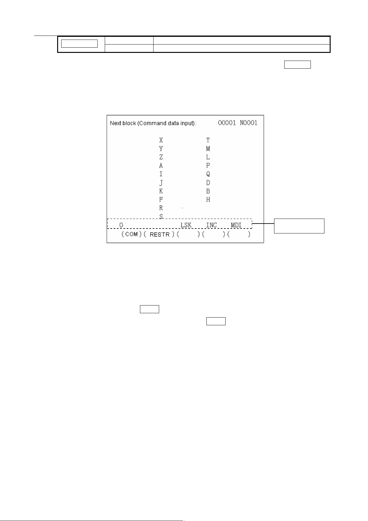
4.4.9 Operating through MDI (function key COMMAND)
A program instruction to be executed may be input through MDI&DPL panel.
(1) Example: X 10.5 Y200.5
(a) Set the selector switch to MDI position.
(b) Press the COMMAND button.
(c) Press the PAGE button. “Next block (command data input)” appears on the upper left of the
screen.
27
Page 34

GSK983M Milling CNC System Operation Manual (Volume II: Operations)
(d) Press the X , 1 , 0 , • and 5 keys and the INPUT button in succession. If the
numeral entered before pressing the INPUT button is incorrect, press the CANCEL button
and enter the correct numeral again. If an error is found after pressing the INPUT button, it
is necessary to enter the numeral again.
(e) Press the Y , 2 , 0 , 0 , • and 5 keys and the INPUT button. If the typed numeral
is found incorrect, proceed in the same way as inputting X.
(f) Press the CYCLE START button on the control panel of the machine.
(2) Delete Y200.5 from X10.5 Y200.5 before pressing the CYCLE START button.
(a) Press the Y , CANCEL and INPUT in succession.
(b) Press the CYCLE START button on the control panel.
(3) Delete modal data.
Since G code and F, D and H data cannot be deleted, it is necessary to input correct modal data
again for modification.
4.4.10 Start of MDI motion
Press the CYCLE START button to execute the instruction input through MDI.
4.4.11 Reset
As a rule, pressing the RESET button cancels alarm state.
Once the RESET button is pressed, the NC system is set to the following states:
28
Page 35

GSK983M Milling CNC System Operation Manual (Volume II: Operations)
State before reset State after reset
In execution of a move
instruction
M, S, T or B
In transfer
MDI mode The contents of the buffer memory are not eliminated. Storage 1 of
buffer
memory,
block
In any case, pressing the RESET button sets the NC system to reset state. In the modes other
than MDI, the NC system is set to the LABEL SKIP mode.
Mode other
than MDI
mode
The tool slows down and stops and the remaining travel
disappears.
The transfer sequence stops. Refer to the manual supplied
with the machine for the state of the machine now.
The contents of the buffer memory are eliminated and the
BUF label disappears.
4.4.12 Tool position offset
The setting display of tool radius compensation (function button: OFFSET)
(1) Press the OFFSET button.
(2) Press the PAGE button and display the required page.
Position offset No. 1-12 of page 1;
Position offset No. 13-24 of page 2;
Position offset No. 25-32 or 25-36 (optional) of page 3;
Position offset No. 37-48 (optional) of page 4;
┋┋
Position offset No. 97-99 or 97-108 (optional) of page 9;
┋┋
Position offset No. 193-200 (optional) of page 17;
The indication of page 1 of position offset
(3) Move the cursor to the offset number to be changed.
Method 1: Press the cursor button and move the cursor in succession. The next page will be
switched to once the cursor goes beyond the current page.
Method 2: Set by typing with N , variable number and INPUT.
(4) Set the SELECTION MODE switch to a mode other than EDIT.
29
Page 36

GSK983M Milling CNC System Operation Manual (Volume II: Operations)
(5) Type P and POSITION OFFSET and then press the INPUT button.
The figure below is the page after P , 1 , 5 , • , 4 and INPUT is pressed when the
position offset number is 19.
Note 1: When offset is changed in automatic operation, the new offset is not valid until its number
is specified as D or H code.
Note 2: 0-9999 INPUT is used to reset all offsets to zero.
4.4.13 Setting and display of workpiece origin offset (Optional)
(1) Press OFFSET twice to display the WORKPIECE OFFSET page.
(2) Press the PAGE button to display the required page. Each page indicates as follows:
(i) Page 1(Workpiece coordinate offset 01)
00: Workpiece coordinate offset
01: The origin offset of the workpiece in workpiece coordinate system 1 (G54)
02: The origin offset of the workpiece in workpiece coordinate system 2 (G55)
03: The origin offset of the workpiece in workpiece coordinate system 3 (G56)
(ii) Page 2(Workpiece coordinate offset 02)
04: The origin offset of the workpiece in workpiece coordinate system 4 (G57)
05: The origin offset of the workpiece in workpiece coordinate system 5 (G58)
30
Page 37

GSK983M Milling CNC System Operation Manual (Volume II: Operations)
06: The origin offset of the workpiece in workpiece coordinate system 6 (G59)
(3) Move the cursor to the number to be changed.
Method 1: Press the cursor button ↑ or ↓ and move the cursor in succession. The next
page will be switched to once the cursor goes beyond the current page.
Method 2: Set by typing with N , NUMBER and INPUT.
(4) Set the SELECTION MODE switch to a mode other than EDIT.
(5) Type X , Y , Z or 4TH/5TH and the offset to be changed or set. Then press the INPUT
button.
The setting range of the workpiece coordinates is 0 mm to ±7.999 mm or 0 inch to ±7.999 inch.
4.4.14 Measurement of tool length
(1) Press the OFFSET button to select the page of offset.
(2) Select a standard tool and manually move it until it contacts the fixed point of the machine (or
fixed point of workpiece).
(3) Press the Z and SHIFT buttons so that the relative coordinates of Axis Z is reset to zero.
(4) Then select the tool to be measured and manually move it until it contacts the same fixed point.
Now the difference between the standard tool and that to be measured is indicated in the display
of relative position.
(5) Just like the setting of offset, move the cursor to the offset number and press the Z and INPUT
keys but do not type in any numeral. The measured difference now is the offset to be input.
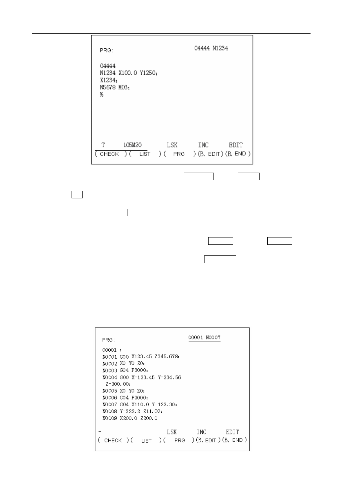
4.4.15 Program display (function button PROGRAM)
(1) When in EDIT mode, press the PROGRAM key to display the page of the selected character in
the current selection program.
31
Page 38

GSK983M Milling CNC System Operation Manual (Volume II: Operations)
See the program number in Section 4.16 for which program is displayed. Pressing the cursor ↓
or ↑ key displays the contents of the program in sequence. When the cursor ↓ key is
pressed, the page is displayed in forward direction. When the cursor ↑ key is pressed, it is
displayed in reverse direction.
(Note 1) Set the SELECTION MODE switch to EDIT and press the PROGRAM button to display
the contents of the program at the beginning of an executing or executed block. However, the
beginning of the program will be displayed when it is returned to (see 4.4.24.4).
(2) In automatic operation
Press the PROGRAM button to display the current executing block.
Indications of the cursor (in automatic operation)
(a) When the cursor blinks, it indicates the block to be executed next time.
(b) When the cursor does not blink, it indicates the currently executing or executed block.
(3) Note 1: Strictly speaking, when the buffer register becomes empty neither in automatic operating
state nor in feed hold state, the blinking of the cursor indicates the next block is going to read in
the buffer register so as to continue to execute a program.
Note 2: When the PAGE button or cursor button is pressed in EDIT mode to move the cursor and
the program is started in memory mode, the block at the cursor in EDIT mode is read in the
buffer register.
(4) EDIT mode and the other modes except automatic mode
When the PROGRAM button is pressed, the executing and executed blocks are displayed on
the left side of the page and the blocks to be executed next time on the right side.
32
Page 39

GSK983M Milling CNC System Operation Manual (Volume II: Operations)
Note: When an angle moves in G28, G29, a fixed cycle and tool radius compensation, the
contents on the left and right of the page are the same for the situation in which a block causes
the cycle movement of several blocks.
4.4.16 Program number search (function key PROGRAM)
When several programs are stored in memory, it is possible to search one of them.
0 1001 0 3054 0 1972
Search a program number
(1) Method 1
(a) Select a mode (EDIT or AUTO).
(b) Press the PROGRAM key.
(c) Enter O and the program number to be searched and then press the cursor ↓ key.
The switching page of the program is displayed after search.
(2) Method 2
(a) Select the AUTO mode.
(b) Press the PROGRAM key.
(c) Press O , CANCEL and the cursor ↓ in sequence. The next stored program is
displayed.
(3) Method 3
(a) Select the EDIT mode
(b) Press the PROGRAM key.
(c) Press O and the cursor ↓ to display the next stored program. In addition, the stored
programs are displayed in sequence for reviewing the stored program numbers when the
cursor ↓ key is pressed continuously.
Note 1: The start position is returned to when the stored program numbers are displayed.
Note 2: The contents in the buffer register are deleted when search a program number.
4.4.17 Inputting a program with keys
A program may be directly stored in memory with the MDI keys.
(a) Select the EDIT mode.
(b) Press the PROGRAM button to display the current program.
(c) Enter the program number to be stored. A new page appears when the O , the program
number and INSERT keys are pressed.
33
Page 40

GSK983M Milling CNC System Operation Manual (Volume II: Operations)
(d) Type in a block
[Example] When typing in G92 X500.0 Y200.0 M12,
G 9 2 X 5 0 0 . 0 Y
2 0 0 . 0 M 1 2 EOB
(e) If a typed character is incorrect, press the CANCEL key to delete the lastly typed word.
Pressing the CANCEL key continuously deletes the typed words one by one from the last
typed one. If the number of the characters of a block exceeds 32, the program cannot be
entered. Now it is possible to divide the block with proper breakpoint.
(f) If the typed program is correct, press the INSERT key.
34
Page 41

GSK983M Milling CNC System Operation Manual (Volume II: Operations)
(g) Enter blocks in succession by this means.
(h) For correcting a typed block, proceed as indicated in the section of Program edit.
(i) For restart, continuously move the cursor to the lastly typed character. The procedure is the
same as insertion.
(j) When all programs are input and at the end of the procedures, press the RESET key if you
want to return to the start position.
4.4.18 Deletion of a program
(Program protection lock is active; function button PROGRAM) Deleting a program stored in
memory:
(a) Select the EDIT mode.
(b) Press the PROGRAM button.
(c) Press O , the program number and DELETE. The program whose number is entered is
deleted.
4.4.19 Deletion of all programs
(Program protection lock is active; function button PROGRAM) Deleting all programs stored in
memory:
(a) Select the EDIT mode.
(b) Press the PROGRAM button.
(c) Press O , - , 9 , 9 , 9 , 9 and DELETE.
4.4.20 Sequence number search
(Function button PROGRAM)
Sequence number search is usually used to search a sequence number in the midway of a
program and start or restart the program from the block whose sequence number is searched. Its
skipping over blocks exerts no influence on the NC system. Namely when skipping over blocks,
the coordinates of the blocks who are skipped over, M, S, T or G codes do not change the
coordinates and modal values of the NC. When a macro is supplied, sequence number will not
be displayed in search.
Therefore, necessary M, S, T, G codes and coordinate system shall be set for the blocks to be
started or restarted according to sequence number. If the block needs to restart search during
machining, MDI must be used to assume M, S, T, G codes and coordinate system so that the
35
Page 42

GSK983M Milling CNC System Operation Manual (Volume II: Operations)
present state of the machine and NC system can be searched.
(a) Select the AUTO mode.
(b) Select the program number where the sequence number to be searched belongs to.
0………………
Selected program
Search range
To search the sequence number on the block, follow (c). When the sequence number to be
searched does not exist on the block, however, the program number with a pre-search
sequence number shall be selected for sequence number search.
(c) Press the PROGRAM button.
(d) Type in N and the sequence number to be searched. Then press the cursor ↓ to find
the sequence number.
Note 1: Coordinates and modal data do not update during search. These data are set through
MDI after search.
Note 2: The following items are checked during search.
TH check
TV check
Skipping over optional blocks
Alarm check (03, 04, 05 and 10)
Note 3: M98P×××× (calling a subprogram) is not executed during sequence number search.
Therefore, when the sequence numbers in the subprogram called by the current
selected program for search in AUTO mode, No. 060 alarm will be given.
In the following example, alarm will be given when N8888 is searched.
4.4.21 Restart of a program
When the machine restarts after the damage of the tool and stop of machining, the restart
function starts the machine from a block to be restarted according to the specified sequence
number.
(1) The tool is damaged (method P)
(a) Press the FEED HOLD button, retract the tool and replace a new tool. Change the offset
when necessary.
(b) Set the PROGRAM RESTART button on the operation panel to ON.
(c) Press the PROGRAM button to display the present program.
(d) Press the cursor ↑ button to return to the starting point of the program.
36
Page 43

GSK983M Milling CNC System Operation Manual (Volume II: Operations)
(e) Press the P, the sequence number and the cursor ↓ to search the block to be restarted.
If the same sequence number appears for many times, e.g. when sequence number search
calls a subprogram for many times, the higher four digits are specified as the number of
times of block appearance and the lower four digits as its sequence number.
P 1 2 3 4 0 1 2 3 Cursor ↓
Number of times Sequence number
The number of times is 1, the higher four digits can be omitted. The preceding zero can also
be omitted when the number of times is established.
(f) After search, LCD changes to display the page for program restart.
The TARGET POSITION indicates the restarting position of machining.
The DISTANCE TO GO indicates the distance from the current tool position to the restarting
position of machining.
M indicates the M codes instructed in the last 35 times.
T indicates the T codes instructed in the last 2 times.
S indicates the last instructed S code.
B indicates the last instructed B codes.
The first instructed code is indicated.
The program restart instruction or the CYCLE START instruction for eliminating each code
in reset state is also indicated.
(g) Set the program restart switch to OFF.
(h) Observe the page. Output by the MDI panel in MDI mode if the M, S, T and B codes to be
output exist. In this case, the M, S, T and B codes to be output no longer appear on the
program restart page.
(i) When the tool moves to the machining restarting position in AUTO mode, check the
distance indicated by DISTANCE TO GO is correct and the tool does not contact workpiece.
Press the CYCLE START button after manually moves the tool to the position that does not
contact the workpiece. Now the tool moves to the restarting position in the sequence of the
th
axis, axis X, axis Y and axis Z and restart machining.
4
(2) Restart machining (Q type) after the occurrence of the following conditions.
(a) Disconnect the power supply.
(b) Press the EMERGENCY STOP button
37
Page 44

GSK983M Milling CNC System Operation Manual (Volume II: Operations)
(c) The machine immediately stops due to storage type travel limit alarm.
(d) The coordinate system changes after the last automatic operation.
Example:
(i) Specify G92 instruction through MDI.
(ii) Move the coordinate system.
(iii) Set the automatic coordinate system after returning to the reference point.
(iv) Press the SHIFT button.
(v) Owing to reset, the change of coordinate system, etc.
(a) After switching on or the release of emergency stop and travel limit alarm, the machine
returns to the reference point before restart (see the Notes below)
(b) The tool is moved to the programmed starting point of machining by manual and the set
modal data and coordinate system is identical with the restart of the machine.
(c) If necessary, set or change the offset.
(d) Set the PROGRAM RESTART button on the operation panel of the machine to ON.
(e) Display the program by pressing the PROGRAM button. Search the required program when
it is not available.
(f) Return the program to the origin point. Press the cursor ↓ button in automatic operating
mode.
(g) Search the sequence number that the block restarts by pressing the Q and cursor ↓
button and typing in the sequence number.
When the same sequence number appears for many times during search, the higher four
digits are specified as the number of times of sequence number appearance and the lower
four digits as its sequence number.
(h) After search, LCD turns to display the page for program restart.
(i) Set the program restart switch to OFF.
(j) Observe the page. Output by the MDI panel in MDI mode if the M, S, T and B codes to be
output exist. In this case, they no longer appear on the program restart page.
(k) When the tool moves to the machining restarting position, check that the tool does not
contact workpiece. If necessary, manually move the tool to the position that does not contact
the workpiece.
(l) Check that the distance indicated by the DISTANCE TO GO is adequate.
(m) Return to the AUTO mode and press the CYCLE START button. Now the tool moves to the
restarting position in the sequence of the 4
th
axis, axis X, axis Y and axis Z and restart
machining.
Note 1: The following conditions, pressing the P button, the sequence number and the cursor
↓ button do not restart the program.
(a) After switching on, no automatic operation is performed.
(b) Automatic operation is performed after the release of emergency stop or storage type travel
limit alarm.
(c) The coordinate system is established, changed or moved (the change in the offset of the
origin of the external workpiece). The automatic operation is performed.
The above (a), (b) or 94—97 alarm reset causes P/S 97 alarm.
P/S 94 alarm caused by the establishment of a coordinate system;
P/S 95 alarm caused by the travel of a coordinate system;
P/S 96 alarm caused by the change of a coordinate system.
The block for the restartable machining is one of the many blocks. The block follows the block
38
Page 45

GSK983M Milling CNC System Operation Manual (Volume II: Operations)
when the coordinate system is last set of changed before the interruption of machinating.
Note 2: In P mode or Q mode, the tool moves to the machining restarting position by traveling by
one axis each time. The stop of a single block is possible after the motion of the axis. However,
JOG operation rather than MDI operation can be inserted. The returned axes cannot move.
Note 3: When move signal, offset and other conditions are different from the past, the tool cannot
return to the machining restarting position identical with the past. The single block switch is set to
ON or AUTO mode is switched to for continuous search operation.
Note 4: When feed hold is active during search or reset operation is performed after search, make
sure to carry out program restarting operation from the beginning. After the end of search, however,
the parameter No.007 “CLEAR Pos” shall be changed to reset state in MDI mode.
Note 5: CYCLE START can be ignored provided that the automatic restart switch of program is
set to ON position.
Note 6: Always bring the JOG absolute switch for ON position for JOG operation no matter it is
before or after machining.
When a program restarting operation instead of resetting is performed after JOG operation or
when JOG operation is performed along the axis that has not returned to the machining
restarting position, the concerned motion is performed once the manual absolute switch is set to
ON position regardless that the manual absolute switch is in ON or OFF position.
Note 7: In principle, the tool cannot return to the correct position in the following cases:
(a) The manual absolute switch is brought to OFF position for JOG operation.
(b) The tool is moved in the lock state of the machine or after the cancellation of axis Z
instruction.
(c) Mirror image function is used.
(d) The coordinate system is not set at the beginning of incremental Program edit.
(e) JOG operation is inserted during the return of an axis.
(f) Machine lock is disabled after the program restart is instructed.
(g) Program restart instruction is given during the execution of the cutting program with skip or
the blocks of an absolute instruction.
(h) A coordinate system is established after search. Nevertheless, in the condition of (c) the
return of the tool in P mode in the block executed by setting the mirror image machining
switch to OFF position as well as the blocks that follow. In this case, the mirror image
machining state is the same as interruption. No alarm is given in any case.
Note 8: When the specified block only includes M98, M99, macro calling instruction (M65, G66
and G67) or macro statement, or no specified block is searched, No.60 alarm will be given.
Note 9: When program restarting operation is instructed and G28 is detected without returning to
the reference point after power on or cancellation of emergency stop or travel limit alarm
(immediate stop), P/S alarm (98) will be resulted in.
Note 10: After the end of search, P/S alarm (99) is given when a move instruction is executed
through MDI operations before axis motion.
Note 11: After the program restart is instructed, “RESTR blinks at the button of the LCD screen
before the return of the last axis (Z).
Note 12: When the block before the restart block has G28, G30, an instruction or incremental
instruction, the absolute position of the 4
case, the 4
th
axis is an axis of rotation and the direction of returning to the reference point is
th
axis can be displayed in the range of 360°. In this
negative.
4.4.22 Program number comparison stop function
The function is used to stop machining after an instruction is executed to the preset sequence
number.
39
Page 46

GSK983M Milling CNC System Operation Manual (Volume II: Operations)
(a) Select the MDI mode.
(b) Press the SETTING button to display the SET page. Move the cursor to the set number 180
by pressing the cursor ↑ or ↓ key. The cursor cannot be moved with address N.
(c) Type the instruction in the sequence of P , the sequence number to be stopped and
INPUT.
(d) Select the AUTO mode and get ready for operation by setting the machine.
(e) Press the CYCLE START button.
The machine stops after the data in the block whose sequence number has been
predetermined in step (c).
The predetermined sequence number is cleared while the machine is stopping.
To perform another comparison stop, repeat the above procedures from (a).
Note 1: Sequence number O cannot be used for comparison stop
Note 2: The predetermined sequence number is cleared by setting.
4.4.23 Display of parameters (function button: PARAMETER)
Press the PARAMETER button to display the parameters, which are laid out in several pages.
Find the desired parameter by pressing the PAGE button (see Appendix 5 for the meanings of
parameters).
4.4.24 Program edit
(Function button: PROGRAM)
The function is used to modify the stored programs.
(1) Set the SELECTION MODE switch to EDIT.
(2) Press the PROGRAM button.
(3) Select a program. Proceed with (4) if the program has been selected; otherwise perform
program number search.
(4) Search the words to be modified by scanning or word search.
(5) Modify, insert or delete the words.
Note 1: Definition and edit unit
A word comprises an address and the numeral that follows. For user macro, however, the
concept of word is indefinite. Hence the concept of “edit unit” is adopted. Edit unit serves as the
object of modification and deletion in a single operation and moves the cursor to its beginning in
a single pass. For data insertion, the data is inserted behind the edit unit.
Definition of edit unit
① From one address to the next one;
② An address is a letter symbol: WHILE, GOTO, END, DO, =, or ; (EOB)
According to the definition, a word is also an edit unit. On the basis of the following explanations
about edit, strictly speaking, word shall be called “edit unit”.
Note 2: During program execution, machining is temporarily suspended by single block
skipping, feed hold and other functions. Nevertheless, continuing to execute a program is not
allowed after program modification, insertion and deletion; otherwise the program cannot be
correctly executed as required by program data. Program is displayed on the LCD after
subsequent machining.
To modify stored data in part program edit mode, they must be modified in reset condition before
program execution or when resetting operation is performed after edit.
40
Page 47

GSK983M Milling CNC System Operation Manual (Volume II: Operations)
4.4.24.1 Word scanning
(1) Press the cursor ↓ button.
The cursor moves forward word by word on the screen. The cursor is displayed underneath the
address character of the selected word.
(2) Press the cursor ↑ button.
The cursor returns word by word on the screen. The cursor is displayed underneath the address
character of the selected word.
Example:
(3) Continuous search can be conducted by pressing down and holding the cursor ↓ or ↑
button.
(4) The next page is displayed and search starts from the beginning of the page by pressing the
page ↓ button.
(5) The previous page is displayed and search starts from the beginning of the page by pressing the
page ↑ button.
41
Page 48

GSK983M Milling CNC System Operation Manual (Volume II: Operations)
(6) Displaying page by page is possible by pressing down and holding the cursor ↓ or ↑ button.
4.4.24.2 Word search
Search a specified word from the present position forward.
N1234×1000 Y1250:X1234:N5678 M03:
Current word X1234 is the object of search.
Search direction
(1) Enter X , 1 , 2 , 3 and 4 with the keypad.
Note 1: The search that only enters X123 and X1234 with the keypad can not be performed.
Note 2: The search that only enters X9 and X009 with the keypad can not be performed. 009
shall be entered with the keypad for the search of X009.
(2) Search starts when the cursor ↓ is pressed. The cursor is displayed underneath X in X1234
after the search.
4.4.24.3 Address search
Search a specified address from the present position forward.
N1234×100.0 Y1250:X1234:N5678, M03:
Current word M03 is the object of search.
(1) Type in M .
(2) Search starts when the cursor ↓ is pressed. The cursor is displayed underneath M after the
search.
Note 1: Pressing the CANCEL button after typing in a numeral deletes the latter and displays a
blank space. Pressing the CANCEL button only indicates CAN.
Note 2: Both word search and address search do not start by pressing the cursor ↑ button.
4.4.24.4 Methods for returning to the beginning of a program
01100 N0001 X12.34: Z15.67: G01×12.5: M04
Beginning Current word
(1) Method 1
A program is displayed from its beginning when the RESET button is pressed in EDIT mode.
(2) Method 2
Perform sequence number search.
(3) Method 3
(a) Set the SELECTION MODE button to AUTO.
42
Page 49

GSK983M Milling CNC System Operation Manual (Volume II: Operations)
(b) Press the PROGRAM button.
(c) Press the cursor ↑ button to return to the EDIT mode for editing a part program.
4.4.24.5 Word insertion (active when the program protection lock is disabled)
Insert T105
(1) Quickly search and scan the word preceding the position where a word is to be inserted.
(2) Type in T , 1 , 0 and 5 and press the INSERT button.
N1234×100.0 Y1250:X1234:N5678, M03:
Object of search
(a) Scan. See 4.24.1.
(b) See 4.24.2 for word search. When Y1250 is in front of the currently indicated position, first
move the cursor to the beginning of the program.
Before insertion
After insertion
Note 1: When what is inserted is not an address but a numeral, the inserted number is added to
the word indicated by the cursor. (Edit unit: In the above example, the insertion of 2.5 will create
43
Page 50

GSK983M Milling CNC System Operation Manual (Volume II: Operations)
Y12502.5 when the cursor is underneath Y in Y1250.
Note 2: A numeral can also be added to all addresses.
E.g. EOB, IF, etc. When the cursor is underneath “;”, the insertion of 23 will create “; 23”.
However, it makes no sense in programming.
4.4.24.6 Word modification (active when the program protection lock is disabled)
N1234×100.0 Y1250:T105: S1234:
To be changed to M15
(1) Search and scan the word to be modified.
(2) Type in M , 1 and 5 and press the ALTER button.
N1234×100.0 Y1250:M15: S1234:
The program is to be modified.
4.4.24.7 Insertion and modification of several words, blocks and strings
Word, block, character string and other information can be inserted (up to 32 characters). In the
example above, to insert T105 M20, type in T105 M20 and press the INSERT button.
Before insertion
44
Page 51

GSK983M Milling CNC System Operation Manual (Volume II: Operations)
After insertion
A word indicated by the cursor can be changed to a word, block or a string, etc.
Note 1: When the cursor is underneath Y in Y1250, the insertion of 25 M20 will become Y1250
2.5 M20.
Note 2: When the cursor is underneath Y in Y1250 T105, the insertion of 2.5 M20 will become
Y1250 2.5 M20.
4.4.24.8 Word deletion (active when the program protection lock is disabled)
(1) Search and scan the word to be deleted.
(2) Press the DELETE button.
N1234 ×100.0 Y1250 T105: X1234:
To delete Y1250
N1234 ×100.0 T105: X1234:
The program after deletion
4.4.24.9 The deletion of the part before EOB
Current word
N1234 ×100.0 Y1250 T105 M13: X1234:
Range of deletion
Press the EOB and DELETE buttons to delete the part before EOB and move the cursor to
the underneath of the address character of the next word.
4.4.24.10 Deletion of blocks (active as program protection lock is disabled)
The range of deletion covers from the currently dedicated word to the block whose sequence
number is specified.
45
Page 52

GSK983M Milling CNC System Operation Manual (Volume II: Operations)
Current word Enter N2233 with the keypad
(1) Type in the sequence number of the last block to be deleted. Type in N , 2 , 2 , 3 and
(2) Press the DELETE button.
N1234 M10;M15×100.0……T0122;N2233 T1200;N3344 Y10.0:
Range of deletion
3 in this example.
4.4.24.11 Storage sorting
The frequent edit of part program sometimes prevents the storage from economic usage,
resulting in the failure to store the program data whose length is specified. Hence it is
necessary to regularly clean up the storage.
Press the CANCEL and SHIFT buttons in succession in the EDIT mode. After sorting, the
admissible number of characters is indicated at the bottom of the screen.
Note 1: For one program, the storage stores the specified length of the program. For many
programs, some storage areas are used to identify these programs.
Note 2: The storage areas to be modified or inserted that exceed the actual length are wasted
in quick part program edit. Storage sorting may eliminate the waste.
4.4.24.12 The indication of all stored program numbers
Once the contents of the storage described in 4.24.11 are sorted, all stored program numbers
are displayed.
4.4.24.13 Edit of user macro (active as the program protection lock is disabled)
User macro may be edited using the SHIFT key. Operate the key in EDIT mode and when the
program protection switch is released. The following points shall be observed.
(a) SHIFT key
Once the SHIFT key is pressed, the cursor (the cursor for keyboard entry: the cursor is in the
position of the character whose data is last input) changes from “—” to “∧”. Press the key with
a character in the lower right angle of the key top in this state. The character in the lower right
angle can be entered.
After entering a character, the cursor restores to the initial “—”. If the SHIFT key is pressed
46
Page 53

GSK983M Milling CNC System Operation Manual (Volume II: Operations)
twice, the cursor also restores the initial “—”.
(Example)
(b) Deletion, insertion and modification of a program
While editing an entered user macro, the cursor moves at the following locations:
(i) At an address
(ii) At the / of an optional block skipped over
(iii) At the left beginning # of a substitution statement
(iv) At (·=)OR;
(v) At the leading character of IF, WHILE, GOTO, END or DO
On the LCD screen, there is a blank space for a character before the above characters.
Deletion, modification and insertion may be performed between the front and rear cursor
positions.
(Example) Cursor position
001x-#100: #1=123; N002 / 2x[12/#3]:
N
003x-SQRT[#3/3*[#4+1]]: N004x-# 2 Y#1:
N
N
005#5=1+2-#10; IF[#1 NE 0]GOTO 10:
HILE[#2LE·B]D01: #[2000+#2]=#2*10:
W
2=#2+1: END1:
#
(Note 1) The cursor cannot be stopped in ( ).
Control OUT/IN
(Example)(#1=100):
The cursor cannot stop here.
(Note 2) The position of the cursor can change with the changed program.
(Example) X
100 Y200: before program modification:
If Y200 is changed into 100 with the ALTER key, it will become X
(c) Abbreviations of macro word
To change or insert a macro word, it can be abbreviated to its first two characters. The
underlined part can alternate the word as an abbreviation.
ILE, GOTO, END, XOR, AND, SIN, COS, TAN,
WH
100 100:
47
Page 54

GSK983M Milling CNC System Operation Manual (Volume II: Operations)
ATAN, SQRT, ABS, BCD, BIX, FUP, RO UND.
(Example): When WH[TA[#1*AB[#2]]LERO[#3]] is entered as data of keyboard entry, the
actual entry will be:
WHILE[TAN[#1*ABS[#2]]LEROUND[#3]]
4.4.25 Indication of run time
Automatic operating time can be accumulated and displayed in hour, minute and second
(increment of 2sec) on the screen.
Time is displayed as indicated in the picture below when the SETTING button is pressed. Press
the PAGE button for other pages.
Note 1: The accumulated time includes automatic operating time but not the single block offtime,
feed hold offtime, etc.
Note 2: If the power supply is switched off immediately after the stop of automatic operation, a
time error up to 6min may be caused after power on again.
Note 3: When necessary, time can be preset through setting operations. The data number is 57,
58 or 59.
4.4.26 Menu switching function
It is possible to enable or disable the switching function of the NC storage using the LCD
instead of the operation panel of the machine.
With this function, the number of switches on the operation panel can be reduced. The following
signals may be switched on or off through the LCD.
(1) Single block (SBK)
(2) Machine lock (MLK)
(3) Dry run (DRN)
(4) Optional block skip 1 to 9(BDT1—9)
(5) Mirror image (MIX, MIY, M14 and M15)
(6) Display lock (DLK)
(7) Auxiliary function lock (AFL)
48
Page 55

GSK983M Milling CNC System Operation Manual (Volume II: Operations)
(8) Axis Z neglected (ZNG)
(9) JOG absolute (ABS)
After the signal data is stored in memory, the switching of these data displayed on the LCD
remains unchanged even the NC power is disconnected.
These signals are not completely replaced by those displayed on the LCD. These signals are
deemed to be switched on no matter whether the machine signals or the signals set on the LCD
are switched on. Accordingly, these signals can be switched on or off through the LCD by
disconnecting the above listed optional signals through the operation panel.
Setting and display: The LCD state of the above signals may be displayed through the following
operations.
Display
(i) Select the set chapter 3
For setting display, press the SETTING button and then press it twice again.
(ii) Press the PAGE button to select the desired page from the two pages than can be
displayed.
Page 1: The part other than optional blocks skipping
Page 2: Optional block skipping 1~9.
Setting
Proceed as follows after the above procedures.
(iii) Move the cursor to the page number to be changed.
Move the cursor to the page number to be changed by pressing the cursor ↑ or ↓ key.
(iv) When the address P is pressed, enter 1 for switching on and 0 for switching off. Press the
keys in the sequence of (P) (entry).
1
2
49
Page 56

GSK983M Milling CNC System Operation Manual (Volume II: Operations)
4.4.27 Operations of LCD soft function keys
4.4.27.1 General
Here function buttons (POSITION, PROGRAM, OFFSET etc) are used as soft function keys.
Their meanings may be displayed on the LCD. All the pages abstained by pressing the soft
function keys are described below.
4.4.27.2 Display
(1) Display of actual position
The actual position of relative coordinate system is displayed on the LCD when the soft function
key REL is pressed.
50
Page 57

GSK983M Milling CNC System Operation Manual (Volume II: Operations)
Press the page ↓ key the update display as shown above. The positions of workpiece
coordinate system and relative coordinate system are exchangeable on the screen.
(2) Display of a program
Press the PROGRAM soft function key to display a program. It is possible to make background
edit (edit the programs other than the currently running programs) using B. EDIT.
Press the PROGRAM soft function key again to display program list. The program list is
displayed as follows.
51
Page 58

GSK983M Milling CNC System Operation Manual (Volume II: Operations)
(3) Display of offsets
When the OFT soft function key is pressed, the offset corresponding to each tool number is
indicated on the LCD. Press the page ↑ or ↓ key and cursor ↑ or ↓ key to select
the desired data. At the same time, the actual position of relative coordinate system is
displayed on the lower part of the LCD.
(4) Display of an instruction
52
Page 59

GSK983M Milling CNC System Operation Manual (Volume II: Operations)
Press the COMMAND soft key. The data displayed on three pages of the LCD appears on the
screen as shown in the above figure. The screen changes as follows when the page ↓ key is
pressed.
(5) Setting
53
Page 60

GSK983M Milling CNC System Operation Manual (Volume II: Operations)
Press the SET soft function key. Now all set data is displayed on the screen. Run time is
displayed in the page of SET DATA 01.
54
Page 61

GSK983M Milling CNC System Operation Manual (Volume II: Operations)
Press the MACRO key. Now the local variable and common variable of user macro are
displayed on the LCD screen.
Press the ON-OFF key. The menu switch window is displayed as shown as shown in Section
4.26 (menu switch function).
(6) Display of alarm and operation information
Pressing the ALM soft function key displays the alarm messages as shown in the above figure.
Pressing the OUTMESS soft function key displays the external information as shown in the
above figure.
55
Page 62

GSK983M Milling CNC System Operation Manual (Volume II: Operations)
(7) Parameter display
Pressing the NC PARA and PC PARA soft function keys to display the relevant parameters on
the LCD.
Pressing the page ↑ or ↓ and cursor ↑ or ↓ to display the desired parameters.
(8) Display of diagnostic data
56
Page 63

GSK983M Milling CNC System Operation Manual (Volume II: Operations)
Pressing the DGN soft function key displays 64 diagnostic data.
Pressing the page ↑ or ↓ and cursor ↑ or ↓ to display the desired diagnostic data.
4.4.27.3 Direct entry of measured workpiece origin offset
The coordinates of the relative coordinate system that offsets at the workpiece origin and is
indicated by the LCD screen may be set as workpiece origin offset. With the function the
relative coordinate system is cleared away at the reference point and the machine is moved to
the workpiece origin by JOG. Now the coordinates of the relative coordinate system may be set
as workpiece origin offset. In this way it is easy to set the workpiece origin offset.
(1) Operating procedures
The relative coordinate system may be cleared away and workpiece origin offset set on the
workpiece origin offset page of the LCD through the following procedures.
(a) Delete the relative coordinate system
Pressing the X and SHIFT keys deletes the relative coordinate system of axis X (this
operation accordingly applies to axes Y and Z as well as the 4th and 5th axes).
(b) Set workpiece origin offset
Press the X and INPUT keys after moving the cursor to the required workpiece offset
number. Then the coordinates of the axis X in the corresponding coordinate system is set
as the axis-X workpiece origin offset of the selected workpiece offset number.
(This operation accordingly applies to axes Y and Z as well as the 4
th
and 5th axes
Note: When the X key is pressed in steps (a) and (b), the X of the relative coordinate
system blinks.
57
Page 64

GSK983M Milling CNC System Operation Manual (Volume II: Operations)
4.5 Position Indication through Position Display Unit (Available upon
Customer’s Request)
The position display unit indicates the actual position. The position display reset buttons are
connected to the position display unit. Each button corresponds to one axis. The position
display of the relevant axis is cleared when any one of the buttons is pressed.
After the absolute origin (G92) is programmed and established, it is indicated on the display unit
through parameter setting (PPD) coordinates.
Note 1: Position pulse cannot be sent to the position display unit when the DISPLAY LOCK
switch is set to ON position. The switch may used to prevent writing offset in position indication
by manually moving the coordinate system.
Note 2: Position is indicated in Inch-system format in the event of entry in inch system.
Position is indicated in metric format in the event of entry in metric system. The RESET button
shall be pressed so that the position indication is zero when the input system is switched from
inch system to metric system, vice versa.
Note 3: Machine compensation data, e.g. amount of clearance compensation cannot be
indicated on the position display unit.
58
Page 65

GSK983M Milling CNC System Operating Manual (Volume II: Operations)
Appendix 1 Codes for Programming
ISO Code EIN Code
Character 8 7 6 5 4 3 2 1 Character 8 7 6 5 4 3 2 1
0
1
2
3
4
5
6
7
8
9
A
B
C
D
E
F
G
H
I
J
K
L
M
N
O
P
Q
R
S
T
U
V
W
X
Y
Z
DEL
○ ○ 0
○ ○ ○ 0 ○
○ ○ ○ ○ ○
○ ○ ○ ○ ○
○ ○ ○ ○ ○
○ ○ ○ ○ ○
○ ○ ○ ○ ○
○ ○ ○ ○ ○ ○ ○
○ ○ ○ ○ ○
○ ○ ○ ○ ○
○ ○ ○
○ ○ ○
○ ○ ○ ○ ○
○ ○ ○
○ ○ ○ ○ ○
○ ○ ○ ○ ○
○ ○ ○ ○ ○
○ ○ ○
○ ○ ○ ○ ○
○ ○ ○ ○ ○
○ ○ ○ ○ ○
○ ○ ○ ○ ○
○ ○ ○ ○ ○
○ ○ ○ ○ ○
○ ○ ○ ○ ○ ○ ○
○ ○ ○
○ ○ ○ ○ ○
○ ○ ○ ○ ○
○ ○ ○ ○ ○
○ ○ ○ ○ ○
○ ○ ○ ○ ○
○ ○ ○ ○ ○
○ ○ ○ ○ ○ ○ ○
○ ○ ○ ○ ○
○ ○ ○ ○ ○
○ ○ ○ ○ ○
○ ○ ○ ○ ○ ○ ○ ○ ○
0
1
2
3
4
5
6
7
8
9
a
b
c
d
e
f
g
h
i
j
k
l
m
n
o
p
q
r
s
t
u
v
w
x
y
z
DEL
○ ○ Numeral “0”
○ ○ "1
○ ○ "2
○ ○ ○ ○ ○ "3
○ ○ "4
○ ○ ○ ○ "5
○ ○ ○ ○ "6
○ ○ ○ ○ "7
○ ○ "8
○ ○ ○ ○ "9
○ ○ ○ ○ Address A
○ ○ ○ ○ ? "B
○ ○ ○ ○ ○ ○ ? "C
○ ○ ○ ○ "D
○ ○ ○ ○ ○ ○ "E
○ ○ ○ ○ ○ ○ "F
○ ○ ○ ○ ○ ○ "G
○ ○ ○ ○ ? "H
○ ○ ○ ○ ○ ○ "I
○ ○ ○ ○ ? "J
○ ○ ○ ○ "K
○ ○ ○ ○ "L
○ ○ ○ ○ "M
○ ○ ○ ○ "N
○ ○ ○ ○ "O
○ ○ ○ ○ ○ ○ "P
○ ○ ○ ○ "Q
○ ○ ○ ○ "R
○ ○ ○ ○ "S
○ ○ ○ ○ "T
○ ○ ○ ○ "U
○ ○ ○ ○ ?
○ ○ ○ ○ "W
○ ○ ○ ○ ○ ○ "X
○ ○ ○ ○ ?
○ ○ ○ ○ "Z
○ ○ ○ ○ ○ ○ ○ ○
Meaning
"V
"Y
Delete
(cancellation
of an incorrect
hole)
*
59
Page 66

Charact
er
NUL
BS
HT
LForNL
CR
SP
%
(
)
+
-
:
/
·
#
$
&
’
*
,
;
<
=
>
?
@
”
[
]
GSK983M Milling CNC System Operating Manual (Volume II: Operations)
ISO Code EIN Code Meaning
8 7 6 5 4 3 2 1
Charact
er
Blank
87654 32 1
No-hole and EIA
codes are not
0
0 *
used in
effective-value
information area
○ ○ 0
○ 0 ○
○ 0 ○
○ ○ 0 ○ ○
○ ○ 0
○ ○ 0○ ○
○ ○ 0
○ ○ ○ 0 ○
○ ○ 0 ○ ○
○ ○ 0 ○ ○
○ ○ ○ 0 ○
BS
Tab
CRorEO
B
SP
ER
(2-4-3)
(2-4-7)
+
-
○ ○ 0 ○ *
○ ○ ○ 0 ○ ○ *
○ 0
0 *
○ 0 *
○ 0 ○ ○
○ ○ 0 ○
○ ○ 0 ○
○ ○ ○ 0 *
○ 0
0
Rewind
( backspace )
Separator
End of block
Return of printer
base
Blank space
End of rewinding
Control OUT (start
of note)
Control IN (end of
note)
Positive sign
Negative sign
As a program
number of ISO
codes
○ ○ ○ 0 ○ ○ ○
○ ○ 0 ○ ○
○ ○ 0 ○ ○
○ 0○
○ ○ 0○ ○
○ 0○ ○ ○
○ ○ ○ 0 ○
○ ○ ○ 0 ○
○ ○ ○ ○ 0 ○ ○
○ ○ ○ 0 ○
○ ○ ○ ○ 0 ○ ○
○ ○ ○ ○ 0 ○ ○
○ ○ ○ 0 ○ ○ ○
○ ○ 0
○ 0 ○
○ ○ ○ ○ 0 ○ ○
○ ○ ○ ○ 0 ○ ○
/
·
&
,
○ ○ 0 ○
○ ○ ○ 0 ○ ○
0 *
0 *
○ 0 ○ ○ *
0 *
0 *
○ ○ ○ 0 ○ ○ *
0 *
0 *
0 *
0 *
0 *
0 *
0 *
0 *
0 *
Stop of block
selection
Full stop (decimal
point)
Well number
Unit number
& (and)
Apostrophe
Asterisk
Comma
Semicolon
Left angular
bracket
Equal sign
Right angular
bracket
Question mark
@ sign
Quotation mark
Left brace
Right brace
60
Page 67

GSK983M Milling CNC System Operating Manual (Volume II: Operations)
(Note 1) “*” code is read in memory only it appears in a note and is invalid in other information areas.
(Note 2) “?” code is read in memory only it appears in a note and causes alarm when it appears
in other information areas.
(Note 3) When a user macro is selected, the following codes are usable in the effective
information areas.
For ISO: +, [, ], #, *, =, B, C, H, J, V, Y.
For EIA: +, [, ], &, the codes set by parameter and B, C, H, J, V, Y.
(Note 4) The codes not listed in the table are ineffective even its parity is correct.
(Note 5) The use of a code with incorrect parity may cause TH alarm. But it is ignored in notes
and does not cause TH alarm.
(Note 6) The output of all the eight digits does not cause alarm for EIA code.
61
Page 68

GSK983M Milling CNC System Operating Manual (Volume II: Operations)
Appendix 2 G Codes List
G Codes Group No. Function
G00* Positioning (quick)
G01* Linear interpolation (cutting feed)
G02 Arc interpolation CW (clockwise circle)
G03
G04 Suspension
G07 imaginary axis designation
G09 Accurate stop check
G10
G17* To select XY plane
G18 To select ZX plane
G19
G20 To input in inch system
G21
G22 Storage travel limit ON
G23
G27 Reference point return check
G28 To return to reference point
G29
G30 To return to the 2
G31
G33 01 Thread cutting
G40* To cancel tool compensation
G41 Tool compensation – left side
G42
G43* Tool radius compensation, +
G44* Tool radius compensation, -
G49*
G45 To increase tool offset
G46 To reduce tool offset
G47 To increase tool offset by twice
G48
G50* Zooming OFF
G51
G54* To select workpiece coordinate system 1
G55 To select workpiece coordinate system 2
G56 To select workpiece coordinate system 3
G57 To select workpiece coordinate system 4
G58 To select workpiece coordinate system 5
G59
G60 00 One-way positioning
G61 Accurate stop detecting mode
G62 To enable automatic angle adjustment
G64*
G65 00 Simple recall of a user macro
G66 Modal recall of microinstruction
G67*
G73 Gun drilling cycle
G74 Left-handed tapping cycle
G76
01
00
02
06
04
00
08
00
11
14
15
2
09
Arc interpolation CCW(counterclockwise circle)
Offset, work zero offset setting
To select YZ plane
To input in metric system
Storage travel limit OFF
To return from reference point
To skip over cutting
Tool compensation – right side
To cancel tool length compensation
To reduce tool offset by twice
Zooming ON
To select workpiece coordinate system 6
Continuous cutting mode
To cancel modal recall of microinstruction
Finish boring
nd
, 3rd and 4th reference points
62
Page 69

GSK983M Milling CNC System Operating Manual (Volume II: Operations)
G80* To disable fixed cycle
G81 Drilling cycle, spotter
G82 Drilling cycle, counter boring
G83 Depth drilling cycle
G84 Tapping cycle
G85 Boring cycle
G86 Boring cycle
G87 Reverse boring cycle
G88 Boring cycle
G89 Boring cycle
G90* Absolute-value programming
G91*
03
Incremental-value programming
G92 00 Coordinate system setting
G94* Feed per minute
G95
G96 Feed at constant speed
G97*
G98* To return fixed cycle to the initial point
G99
05
13
10
Feed per rotation
To cancel constant speed control
To return fixed cycle to point R
(Note 1) The G codes marked with * are the initial G codes of all groups. That is, these G codes are
established when power on or pressing the RESET key (the system parameters specifying
initial G codes are validate).
The selection of the state of the initial G codes such as G00, G01, G43, G44, G49, G90, G91
or G94 and G95 shall be set by parameters (G00, G43, G44, G90 and G95).
For G20 or G21, it becomes the state before power off.
(Note 2) The G codes in group 00 are modal and are only valid in the blocks they belong to.
(Note 3) When a G code not listed in the above table is specified or an optional G code not defined by
control unit is specified, (N0.010) will give an alarm. (N0.010) But G38 and G39 are ignored.
(Note 4) Some G codes may be specified in the same block even they do not belong to the same group.
When 2 or more G codes than belong to the same group are specified in a block, the lastly
specified G code will be valid.
(Note 5) If any G code in group 01 in fixed cycle mode, the fixed cycle will be automatically disabled and
the system will be in G80 state. However, the G codes in group 01 are not subject to the
influence of the G codes of fixed cycle.
(Note 6) G70 and G71 replaces G20 and G21 (special G codes) by parameter setting (GSP).
(Note 7) The G codes of all groups are displayed.
63
Page 70

GSK983M Milling CNC System Operating Manual (Volume II: Operations)
Appendix 3 Ranges of Instruction Values
Minimum setting unit
Maximum travel (the value starts
from reference point)
Max. instruction value
When
adjusting
cutting feed
by 100%
Feedrate at high speed (all axes
are independent)
Upper limit of cutting feedrate
Manual feedrate
F0
Feed per minute
Input in mm
Output in mm
0.001mm
0.001°
±99999.999mm ±99999.999mm ±3937.0078inch ±99999.999inch
±99999.999mm
±99999.999°
1 mm/min
to 15000
mm/min
30 mm/min to
15000
mm/min
6 mm/min to
15000
mm/min
Input in inch
Output in mm
0.0001inch
0.001°
±3937.0078inch
±99999.999°
0.01 inch/min to
600.00
inch/min
30 mm/min to
15000
mm/min
6 mm/min to
15000
mm/min
Input in mm
Output in inch
0.001mm
0.001°
±99999.999mm
±99999.999°
1 mm/min to
15000
mm/min
3.0 inch/min to
600.0
inch/min
0.6 inch/min to
600.0
inch/min
Input in inch
Output in inch
0.0001inch
0.001°
±99999.999inch
±99999.999°
0.01 inch/min to
600.00
inch/min
3.0 inch/min to
600.0
inch/min
0.6 inch/min to
600.0
inch/min
1 mm/min to
JOG feedrate
Coordinates of 2nd reference
point (the value starts from
reference point)
Tool offset
Minimum value of incremental
feed
Clearance compensation 0mm to 0.255mm
Compensation of screw pitch
error
Setting range of storage travel
limit (the value starts from
reference point)
Pause 0s to 99999.999s
2000
mm/min
0 mm to ±
99999.999mm
0 mm to ±
99999.999mm
0.001mm 0.0001inch 0.001mm 0.0001inch
0mm to
±0.007mm
0mm to ±
99999.999mm
0.04 inch/min to
78.7
inch/min
0 mm to ±
99999.999mm
0 inch to ±
99999.999inch
0 mm to
0.255mm
0mm to
±0.007mm
0mm to ±
99999.999mm
0s to
99999.999s
0.5 mm/min to
1016
mm/min
0 inch to
±3937.0078inch
0 mm to
±99999.999mm
0 inch to
0.255inch
0inch to
±0.007inch
0inch to
±3937.0078inch
0s to 99999.999s
0.02 inch/min to
40
inch/min
0 inch to
±99999.999inch
0 inch to
±99999.999inch
0 inch to
0.255inch
0inch±0.007inch
0inch to
±99999.999inch
0s to
99999.999s
64
Page 71

GSK983M Milling CNC System Operating Manual (Volume II: Operations)
Appendix 4 Calculating Chart
A4.1 The tool path in a turning angle section
(1 ) Summary
Due to the delay of servo system (as a result of exponential deceleration/acceleration during
cutting or the use of the positioning system of a DC servo motor), a minor deviation exists
between the tool path (tool center path) and instructed path as shown in Fig. 4.1 (a). In this
center, the time constant T1 of exponential deceleration/acceleration is fixed to 0.
Fig. 4.1 (a): The tool path regarding a turning angle section
The tool path depends on the following parameters:
(a) Feedrate (V
(b) Degree of the turning angle (θ)
(c) Time constant (T
(d) Loop gain of positioning system
(e) Existence of buffer
This document makes theoretical analysis of tool path with the above parameters. The tool path
of temporarily set parameters is displayed in graph.
The above notes shall be observed for programming. Note whether the machining shape is
within the desired accuracy range.
That is, when it is possible to reach the theoretical accuracy, hold for a proper time using the
suspension function until the instruction speed drops to zero before reading in the next block.
, V2)
1
)(T1 = 0) of exponential deceleration/acceleration during cutting
1
(2) Analysis
In the following conditions, make analysis of the tool path as shown in Fig. 4.1(b).
(a) Feedrate remains constant in the blocks before and after the turning angle.
(b) The control is provided with a buffer (error changes with the reading rate of the input
equipment and the number of characters of the next block).
65
Page 72

GSK983M Milling CNC System Operating Manual (Volume II: Operations)
V
1 = V·cosφ1
X
VY1 = V·sinφ1
V
2 = V·cosφ2
X
V
2 = V·sinφ2
Y
π-(φ1-φ2)=θ
[Explanations for the symbols]
V: Feedrate in the blocks before and after turning angle
V
1: X component of the feedrate in the previous block
X
V
1: Y component of the feedrate in the previous block
Y
V
2: X component of the feedrate in the next block
X
V
2: Y component of the feedrate in the next block
Y
θ: Angle of the turning angle
φ1: The included angle between the direction of the instruction path in the previous block and
axis X
φ2: The included angle between the direction of the instruction path in the next block and axis
X
66
Page 73

GSK983M Milling CNC System Operating Manual (Volume II: Operations)
Calculation of initial value
The initial value at the beginning of a turning angle, i.e. the X and Y coordinates at the end of
the distribution of the control unit are determined by the time constant of the positioning system
of the used DC motor.
X
= Vx1(T1+T2)………(1) Y0 = Vy1(T1+T2)………(2)
0
T
: Time constant (T1 = 0) of exponential deceleration/acceleration
1
T
: Time constant (reciprocal of position loop gain) of positioning system
2
Analysis of tool path
The feedrates in the directions of axis X and Y in the turning angle are expressed in the
following formulas.
⎞
Vx(t)=(Vx
-Vx1)[1-
2
⎞
Vx1
{ }
T
− T
TT
21
⎛
t
⎟
⎜
1
−×
⎜
⎝
T
⎟
T
1
⎠
⎛
t
⎟
⎜
2
−×−
⎜
⎝
Vx1]expexp
+
⎟
2
⎠
Vy(t)=
= Vx
⎡
2
−
1
⎢
T
⎢
⎣
VyVy
−
T
−
T
21
Vx1
+
⎧
⎪
21
⎨
⎪
⎩
⎧
⎪
T
⎨
1
T
⎪
21
⎩
⎛
⎜
T
1
−×
⎜
T
⎝
⎞
⎛
t
⎟
⎜
−×
⎜
⎝
⎞
t
⎟
⎟
1
⎠
T
⎟
T
1
⎠
T
2
⎛
⎜
expexp
2
⎜
⎝
⎞
⎛
t
⎟
⎜
−×−
⎟
⎜
T
2
⎠
⎝
⎤
⎫
⎞
t
⎪
……………………(3)
⎟
−×−
⎫
⎪
⎬
⎪
⎭
⎥
⎬
⎟
T
⎪
⎥
2
⎠
⎭
⎦
……………………(4)
Vyexpexp
+
2
The coordinates of the tool path at time t are calculated with the following formula.
t
X(t)=
=
Y(t)=
=
)( XdttVx
−
∫
0
VxVx
−
TT
−
t
)( YdttVy
∫
0
VyVy
−
TT
−
0
⎧
⎪
2
12
T
⎨
1
⎪
21
⎩
−
0
⎧
⎪
2
12
T
⎨
1
⎪
21
⎩
⎞
⎛
t
⎟
⎜
−×
⎜
⎝
⎛
⎜
−×
⎜
⎝
T
⎟
T
1
⎠
⎞
t
⎟
T
⎟
T
1
⎠
⎛
2
⎜
expexp ……………(5)
2
⎜
⎝
2
expexp ……………(6)
2
⎫
⎞
t
⎪
⎟
−×−
⎟
T
2
⎠
⎞
⎛
t
⎟
⎜
−×−
⎟
⎜
T
2
⎠
⎝
()
⎬
⎪
⎭
⎫
⎪
⎬
⎪
⎭
()
A4.2 Error of radius direction during arc cutting
tTTVx
−+−
212
tTTVy
−+−
212
When using a DC servo motor, a delay is produced between the input and output axes due to
the factors of the positioning system. The linear interpolation on instruction path does not cause
any error. Arc interpolation, especially the arc cutting at high speed may cause a deviation in
the direction of radius, which is determined with the following formula.
Y: Maximum radius error (mm)△
V: Feedrate (mm/sec)
67
Page 74

GSK983M Milling CNC System Operating Manual (Volume II: Operations)
r
r: Arc radius (mm)
T
: Time constant (sec) (T1 = 0) of exponential deceleration/acceleration during cutting
1
T2: Time constant (sec) (reciprocal of position loop gain) of positioning system
△ r =
1
2
()
1
2
V
2
2
TT
2
……………………………………………… (1)
×+
The radius r(mm) and permissible error △r(mm) of a workpiece are given in actual machining.
Permissible speed limit V(mm/sec) can be calculated with the formula (1).
The Time constant of deceleration/acceleration during cutting set by the unit varies with
machine types. Refer to the user manual supplied with the machine.
68
Page 75

GSK983M Milling CNC System Operating Manual (Volume II: Operations)
Appendix 5 Parameters
Display and setting procedures of parameters
When the NC is connected to a servo motor or the machine, the specifications and functions of
the machine shall be set to maximize the performance of the servo motor. Since its contents
vary with machine types, please refer to the additional parameters of the machine. End user is
not allowed to change the parameters.
A5.1 Display of parameter
(a) Press the PARAMETER key.
(b) Select the desired page with the PAGE key, or N , parameter number and INPUT
A5.2 Setting of parameter
Setting in MDI mode
(a) Switch the PRM.WT switch on the main unit to ENABLE (ON) to activate the warning
indicator on the panel.
(b) Set the MDI mode.
(c) Press the PARAMETER key.
(d) Press the N , the parameter number to be set and INPUT. The cursor will appear
underneath the number provided that the page of the parameter number to be set is
selected. (This may also be done with the PAGE button and cursor ↓ or ↑ button. )
(e) Set with P , set data and INPUT.
In the event of error during typing in, press the CANCEL key.
(f) Make sure the setting is correct.
(g) After the setting of all parameters and end of confirmation, return the switch on the main
PCB to DISABLE (OFF).
(h) To terminate the alarm state (No. 100), press the RESET button.
A5.3 Parameters list
Parameter No.
0 0 6
ORWD: Retention parameter
SCTO 1: Perform detection of speed reaching signal during instruction and changing from
0: Not perform detection of speed reaching signal.
EENB 1: Servo OFF signal is active.
0: Servo OFF signal is inactive.
OTCE 1: Stop once the travel switch of hardware is pressed.
ORWD SCTO EENB OTCS FMIC MDL MIC SCW
7 6 5 4 3 2 1 0
quick speed to cutting feed.
(Mechanical position is lost)
0: Slow down and stop once the travel switch of hardware is pressed. (Mechanical
position is not lost)
FMIC 1: When inputting in metric system, the unit of feedrate is 1/10.
0: Not 1/10
MDL 1: The minimum unit of the indication on the position display unit is 0.01mm or input
in metric system and 0.001inch for input in inch system.
69
Page 76

GSK983M Milling CNC System Operating Manual (Volume II: Operations)
0: The minimum setting unit of the indication on the position display unit is 0.001mm
or input in metric system and 0.001inch for input in inch system.
MIC 1: The minimum setting unit of the indication on the position display unit is 0.01mm or
input in metric system and 0.0001inch for input in inch system.
0: The minimum setting unit of the indication on the position display unit is 0.001mm
or input in metric system and 0.0001inch for input in inch system.
SCW 1: The minimum travel unit is 0.0001inch (machine in inch system)
0: The minimum travel unit is 0.001mm (machine in metric system)
0 0 7
ADFT EOM CINP DCS CLER TVC PPD RDRN
7 6 5 4 3 2 1 0
ADET 1: Perform automatic drift compensation
0: Not perform automatic drift compensation.
EOM 1: If M30 is sent to the machine side and FIN returns when M30 is instructed, it is
continuously executed from the preceding block of the program, or the machine
side does not send back FIN signal but external reset signal. The program returns
to the beginning to enter into reset state (in automatic mode).
0: When M30 is instructed, only M30 is sent out to the machine side and the program
does not return to the beginning unless reset and rewinding signal is used (in
automatic mode).
CINP 1: Instruction speed reduces to 0 between two non-cutting blocks. The next block is
not continued until the machine confirms that the designated position is reached
(the confirmation is called positioning detection).
0 The next block is executed once the instruction speed reduces to 0 between two
non-cutting blocks (not perform positioning detection).
DCS 1: The start button on the MDI panel does not pass through the machine side, but
directly is switched on the NC side (only for MDI mode).
0: The start button on the MDI panel is sent to the machine side, and then the start
button on the machine side returns for start.
CLER 1: The NC is brought into clearing state (see Appendix 7 for clearing state) using the
RESET button, external reset signal, reset and rewinding signal.
0: The NC is brought into reset state using the RESET button, external reset signal,
and reset and rewinding signal.
TVC 1: Not perform TV check in the control output section (note section)
0: Perform TV check in the control output section (note section)
PPD 1: Preset the position display unit by setting a coordinate system.
0: Not preset the position display unit during the setting of a coordinate system.
RDRN 1: Dry run is also valid for rapid feed instruction.
0: Dry run is not valid for rapid feed instruction.
70
Page 77

GSK983M Milling CNC System Operating Manual (Volume II: Operations)
0 0 8
ICR GSP G44 G90 G95 G43 G00
7 6 5 4 3 2 1 0
ICR 1: When ISO code is used for output, EOB will be output by LF.
0: When ISO code is used for output, EOB will be output by LFCR CR.
GSP 1: Use a special G code.
0: Use a standard G code.
G90 1: Enter into G90 mode when in power on and clearing state.
0: Enter into G91 mode when in power on and clearing state.
G95 1: Enter into G95 mode when in power on and clearing state.
0: Enter into G94 mode when in power on and clearing state.
G00 1: Enter into G00 mode when in power on and clearing state.
0: Enter into G01 mode when in power on and clearing state.
G44, G43
G44 G43 Initial state
0 0 9
FIX2 1: Output the M code in a fixed cycle (fixed cycle II).
RWL 1: Store the outside of the travel limit 2 as a prohibited area.
MCF 1: Output EF at the end of the positioning of G81 (axis Z does not move).
FMFS 1: Output FMF signal twice in a fixed cycle.
FCUT 1: The travel of the axes X and Y in a fixed cycle uses the G codes in Group 01.
1 0 Enter into G44 mode when in power on and clearing state.
0 1 Enter into G43 mode when in power on and clearing state.
0 0 Enter into G49 mode when in power on and clearing state.
FIX2 RWL MCF FMFS FCUT ILVL EFR1 TDRN
7 6 5 4 3 2 1 0
0: Not output the M code but SSP and SRV in a fixed cycle (fixed cycle II)
0: Store the inside of the travel limit 2 as a prohibited area.
0: Output EF at the end of the positioning of G81 (axis Z moves).
0: Output FMF signal once in a fixed cycle.
0: The travel of the axes X and Y in a fixed cycle usually uses rapid feed.
ILVL 1: Change the initial plane points with the RESET button.
0: Not change the initial plane points even using the RESET button.
EFRI 1: Output EF with a photoelectric coupler
0: Output EF with a relay.
TDRN 1: Also valid for dry run of thread cutting.
0: Invalid for dry run of thread cutting.
71
Page 78

GSK983M Milling CNC System Operating Manual (Volume II: Operations)
0 1 0
TCW CWM SOV SLCC OFSD SOVC ISOT
7 6 5 4 3 2 1 0
Signs for TCW, CWM and S4-digit output
TCW CWM Sign
0 0 M03 M04 are all positive.
0 1 M03 M04 are all negative.
1 0 M03 is positive while M04 is negative.
1 1 M03 is negative while M04 is positive.
SOV 1: Enable main axis adjustment.
0: Disable main axis adjustment.
TLCC 1: The change of offset in G43 and G44 modes starts to take effect from the next
block.
0: The change of offset in G43 and G44 modes starts to take effect from the following
H and D codes.
OFSD 1: Tool position offset (G45 to G48) uses D code.
0: Tool position offset (G45 to G48) uses H code.
SOVS 1: Spindle adjustment is clamped at 100% in tapping.
0: Spindle adjustment is not clamped at 100% even in tapping.
ISOT 1: With the storage type travel limit selection, JOG rapid feed is valid even returning
to the reference point is not performed.
0: With the storage type travel limit selection, JOG rapid feed is valid unless returning
to the reference point is performed.
0 1 1
DGNE SETE DECI SSPB VCT SUPM ADLN
7 6 5 4 3 2 1 0
DGNE 1: Enable data output in diagnosis.
0: Disable data output in diagnosis.
SETE 1: Input setting is possible when the lock key is closed.
0: Input setting is not possible when the lock key is closed.
DECI 1: Decelerate when the decelerating signal is “1” during the return to reference point.
0: Decelerate when the decelerating signal is “0” during the return to reference point.
SSPB 1: Spindle stops when the spindle stop input signal (SSP) is “o”.
0: Spindle stops when the spindle stop input signal (SSP) is “1”.
VCT 1: It is possible to specify tool compensation vector with I, J and K.
0: It is impossible to specify (general automatically calculate).
SUPM 1: Start and cancel type B in tool radius compensation C.
0: Start and cancel type A in tool radius compensation C. (See this document for type
A/B.)
th
ADLN 1: The 4
axis is used as a linear axis.
0: The 4th axis is used as an axis of revolution.
0 1 2
ZGM4 ZGGMZ ZGMY ZGMX ZM4 ZMZ ZMY ZMX
7 6 5 4 3 2 1 0
ZGMX, ZGMY, ZGMZ and ZGM4 are the return-to-reference-point modes for axes X, Y and Z
72
Page 79

GSK983M Milling CNC System Operating Manual (Volume II: Operations)
and the 4th axis respectively.
1: magnetic switch mode 0: grid mode
ZMX, ZMY, ZMZ and ZM4 are the return-to-reference-point directions as well as the initial
directions of clearance when power on for axes X, Y and Z and the 4
th
axis respectively.
1: The return-to-reference-point direction as well as the initial direction of clearance is
negative.
0: The return-to-reference-point direction as well as the initial direction of clearance is
positive.
(Note 1) For an axis with return-to-reference-point function, the return-to-reference-point
direction is identical with the initial direction of clearance. For an axis without
return-to-reference-point function, the parameter only has the meaning of initial direction of
clearance.
(Note 2) After power on, clearance compensation is made when moving in the direction set by
this parameter.
0 1 3
PSG2 PSG1 PHS
7 6 5 4 3 2 1 0
PSG2, PSG The tooth to spindle ratio of spindle and position coder
Override PSG2 PSG1
X1
0 0
X2 0 1
X4 1 0
X5 1 1
Override=
When in PHS and PSCG modes (rotary transformer and inductosyn), the initial setting of
relative offset:
1: does not automatically set phase deviation
0: automatically sets phase deviation. PHS automatically changes to “1” after the setting is
performed once.
0 1 4
DMR X GRD X
7 6 5 4 3 2 1 0
0 1 5
DMR Y GRD Y
7 6 5 4 3 2 1 0
0 1 6
DMR Z GRD Z
7 6 5 4 3 2 1 0
73
Page 80

GSK983M Milling CNC System Operating Manual (Volume II: Operations)
0 1 7
4 1 0
DMR 4 GRD 4
7 6 5 4 3 2 1 0
DMR 5 GRD 5
7 6 5 4 3 2 1 0
DMRX, DMRY, DMRZ, DMR4 and DMR5 are the measuring override ratio for axes X, Y, Z and
th
axis respectively.
the 4
Setting codes
0 0 0
Pulse coder Rotary transformer and inductosyn
1/2
Overrides
1/8
0 0 1 1 1/4
0 1 0 1 1/4
0 1 1 2 1/2
1 0 0 3/2 3/8
1 0 1 3 3/4
1 1 0 2 1/2
1 1 1 4 1
GRDX, GRDY, GRDZ, GRD4 and GRD5 are the capacities of the reference counters for axes X,
Y, Z and the 4
th
axis respectively.
Setting codes Capacity of a cycle
0 0 0 1 2000
0 0 1 0 3000
0 0 1 1 4000
0 1 0 0 5000
0 1 0 1 6000
0 1 1 1 8000
1 0 0 1 10000
(Note) The codes other than those listed in the above table are treated as 8000 capacity.
0 1 8
CPF2 CPF1
3 2 1 0
Pulse frequency (holoaxial calling) for CPF2 and CPF1 clearance compensations.
Frequency, KHZ CPF2 CPF1
32 0 0
64 0 1
128 1 0
256 1 1
(Must be set to 256KHZ)
0 1 9
TMF TFIN
7 6 5 4 3 2 1 0
TMF The time from the send-out of M, S, T and B codes to that of MF, SF, SF and TFBF:
16—126ms (16ms interval).
TFIN The time of FIN signal receiving width: 16—265ms (16ms interval).
74
Page 81

0 2 0
GSK983M Milling CNC System Operating Manual (Volume II: Operations)
T M F T F I N Setting
15m sec
32m sec
48m sec
64m sec
80m sec
96m sec
112m sec
128m sec
144m sec
160m sec
176m sec
192m sec
208m sec
224m sec
240m sec
256m sec
>15m sec
>15m sec
>15m sec
>15m sec
>15m sec
>15m sec
>15m sec
>15m sec
>15m sec
>15m sec
>15m sec
>15m sec
>15m sec
>15m sec
>15m sec
>15m sec
0
0
0
0
0
0
0
0
1
1
1
1
1
1
1
1
0
0
0
0
1
1
1
1
0
0
0
0
1
1
1
1
0
0
1
1
0
0
1
1
0
0
1
1
0
0
1
1
0
1
0
1
0
1
0
1
0
1
0
1
0
1
0
1
CLSI ZTN5 ZTN4 ZTNZ ZTNY ZTNX
7 6 5 4 3 2 1 0
CLSI 1: Not detect servo position circuit LSI.
0: Detect servo position circuit LSI.
ZTNX, Y, Z, 4 and 5 are the availability of return-to-reference-point function for axes X, Y and Z
th
as well as the 4
and 5th axis respectively.
1: With return-to-reference-point function
0: Without return-to-reference-point function
0 2 1
G84S SFOU EDMZ EDMY EDMX EDPZ EDPY EDPX
7 6 5 4 3 2 1 0
75
Page 82

GSK983M Milling CNC System Operating Manual (Volume II: Operations)
G84S 1: When S 12-digit output A and S analog output A are used in fixed cycles G74 and
G84, method B is valid.
0: When S 12-digit output A and S analog output A are used in fixed cycles G74 and
G84, method A is valid (see connection guides for method A/B) .
SFOU For 12-digit outputs A and B as well as analog output A, SF setting is not output in
the output without gear switching.
1: Output SF.
0: Not output SF.
EDMX, EDMY and EDMZ correspond to the negative instructions of axes X, Y and Z
respectively.
1: Valid for rapid feed and external deceleration of cutting feed
0: Only valid for rapid feed.
EDPC, EDPY and EDPZ correspond to the positive instructions of axes X, Y and Z respectively.
1: Valid for rapid feed and external deceleration of cutting feed
0: Only valid for rapid feed.
0 2 2
SIJ PMXY2 PMXY1 RS43 FXCD TAPSG FXCS
7 6 5 4 3 2 1 0
SIJ Setting of tool returning method in fixed cycle G76 or G87
1: Set direction and amount of travel with address I and J.
0: The amount of travel uses address Q as instruction and its direction is determined
by parameters PMXY1 and PMXY2
PMXY2, 1 Setting of tool returning direction in fixed cycle G76 or G87(only valid when SIJ =0)
PMXY2 PMXY1 Returning direction
0 0
0 1
1 0
1 1
+X
-X
+Y
-Y
RS43 1: The offset vectors of G43 and G44 are retained after reset.
0: The offset vectors of G43 and G44 are cleared after reset.
FXCD 1: Dwell instruction is valid in fixed cycles G74 and G84.
0: Dwell instruction is invalid in fixed cycles G74 and G84.
TAPSG 1: Output tapping signal in fixed cycles G74 and G84.
(Valid only when FLX2 = 1).
0: Not output tapping signal.
FXCS 1: M05 is not output and spindle rotates reversely or forward in fixed cycles G74 and
G84 (Valid only when FIX2 = 1)
0: M05 is output and spindle rotates reversely or forward in fixed cycles G74 and
G84
0 2 3
EXIOD
7 6 5 4 3 2 1 0
76
Page 83

GSK983M Milling CNC System Operating Manual (Volume II: Operations)
EXIOD 1: To multiply the unit of external origin offset by 10.
0: Not to multiply it by10.
0 2 4
PML2 PML1 DLME RDAL ADW2 ADW1 ADW0 FMT
7 6 5 4 3 2 1 0
PMC2, 1 Screw pitch error compensation override
The set compensation is output after it is multiplied by the override.
FMT 1: Perform software parity check for part program edit area.
0: Not perform the check.
When it is ready for the check, the parameter is automatically set to 1. It cannot be externally
switched on or off.
PML2 PML1 Override
0 0 ×1
0 1 ×2
1 0 ×4
1 1 ×8
DLME 1: All programs stored before are automatically cleared when storing programs in
memory.
0: Not automatically clear.
RDAL 1: Generally all programs are stored when storing programs in memory.
0: When storing programs in memory, storing a program or all programs is
determined by MDI operations.
th
ADW2, 1, 0 Select the name for the 4
axis in the even of data output or display on LCD.
ADW2 ADW1 ADW0 Address
0 0 0 A
0 0 1 B
0 1 0 C
0 1 1 U
1 0 0 V
1 0 1 W
0 2 5
MUSR MCYL MSUB MPRM TSE
7 6 5 4 3 2 1 0
MSUB 1: Subprogram type user macro terminates.
0: Macro type user
MURS 1: Use user macro look-at-me function
0: Not use.
MCYL 1: User macro terminates in cycle operations.
0: User macro does not terminate in cycle operations
(Note) The local variable for a macro terminated and called by subprogram type user macro
does not change. The local variable for a macro terminated and called by macro type user
macro differs from that is used in the current program.
MPRM 1: That a user macro terminates and controls M codes is set by parameter.
0: The look-at-me of a user macro is controlled by M96 and M97.
TSE 1: The look-at-me of a user macro adopts state triggering mode.
77
Page 84

GSK983M Milling CNC System Operating Manual (Volume II: Operations)
0: Adopt fringe triggering mode.
0 2 6
NGMP OFFVY OGE CKIM
7 6 5 4 3 2 1 0
MGMP The amounts of travel of manual pulse generator are as follows.
NGMP MP2 MP1 Amounts of travel
0 0 0 0.001mm/0.0001inch
0 0 1 0.01mm/0.001inch
0 1 0 0.1mm/0.01inch
0 1 1 0.1mm/0.01inch
1 0 0 0.01mm/0.001inch
1 0 1 0.001mm/0.0001inch
1 1 0 0.1mm/0.01inch
1 1 1 0.1mm/0.01inch
OFFVY 1: Servo alarm is not given even when VRDY is ON before PRDY output.
0: Servo alarm is not given when VRDY is ON before PRDY output.
CKIM 1: Ignore the switching of signal during automatic operation (the state of during
CYCLE START is valid).
0: Immediately enable machine lock signal.
(Note) Machine lock is always active in JOG mode.
1: Storage sorting is not performed during program search.
0: Storage sorting is performed during program search.
0 2 7
CMRX
0 2 8
CMRY
0 2 9
CMRZ
0 3 0
CMR4
4 1 4
CMR5
CMRX, CMRY, CMRZ, CMR4 and CMR5 are the instruction multiplying powers for axes X, Y
and Z as well as the 4
th
and 5th axes respectively.
1 0.5
2 1
4 2
10
5
20 10
0 3 1
VLOCX
0 3 2
VLOCY
0 3 3
VLOCZ
0 3 4
VLOC4
4 1 5
VLOC5
VLOCX, Y, Z, 4 and 5 are the minimum values of speed instruction for axes X, Y and Z as well as
th
the 4
and 5th axes respectively.
78
Page 85

GSK983M Milling CNC System Operating Manual (Volume II: Operations)
0 3 5
MBUF1
0 3 6
MBUF2
MBUF1, MBUF2 Up to 2 settings between 00 and 97 may be set for the M codes without
buffer.
0 3 7
SPGST
SPGST The setting between 0 and 255 for the number of revolutions of spindle motor (S12 or
S analog output A/B) during the shifting of spindle gear.
Setting=
0 3 8
SPSOR
SPSOR Number of revolutions during accurate stop of spindle (S12 or S analog output A/B)
Settings 0 to 255 Unit: rpm
0 3 9
PECZRX
0 4 0
PECZRY
0 4 1
PECZRZ
0 4 2
PECZR4
4 1 6
PECZRX to 5 are the settings of pitch error origin for axes X, Y and Z as well as the 4
PECZR5
th
and 5th
axes respectively.
Settings 0 to 127
Set some points corresponding to the reference point. For example, assuming that the pitch
error origin is set to 0 and the set point 1 is located at +8.000mm, then the compensation range
of the set point 127 at 1016.000mm is 0 mm to 1016.000mm.
79
Page 86

GSK983M Milling CNC System Operating Manual (Volume II: Operations)
This is the occasion that pitch error compensating clearance (parameters 163 to 166) is 8000.
0 4 3
UMMCD4
0 4 4
UMMCD5
0 4 5
UMMCD6
0 4 6
UMMCD7
0 4 7
UMMCD8
0 4 8
UMMCD9
0 4 9
UMMCD10
0 5 0
UMMCD11
0 5 1
UMMCD12
0 5 2
UMMCD13
UMMCD4 to UMMCD13
Up to 10 M codes for calling user macros can be set (assignment of independent variable is also
possible).
Settings 01 to 97
0 5 3
MACINTON
MACINTON: The code for a user macro to terminate its active state.
Settings 03 to 97
The parameters are only valid when the parameter 025—MPRM = 1.
0 5 4
MACINTOF
MACINTON: The code for a user macro to terminate its inactive state.
Settings 03 to 97
The parameters are only valid when the parameter 025—MPRM = 1.
0 5 7
TMHOR (hr)
0 5 8
0 5 9
TMMIN (min)
TMSEC (sec)
TMHOR Display in hour: 0 to 255 (increment: 1 hr)
TMMIN Display in minute: 0 to 59 (increment: 1min) Display during machining time
80
Page 87

GSK983M Milling CNC System Operating Manual (Volume II: Operations)
TMSEC Display in sec: 0 to 58 (increment: 2 sec)
Machining time (when the STL indicator is lit) is displayed in hour, minute or sec by setting.
Machining time is saved in nonvolatile memory even in the event of power failure.
To preset it to zero, proceed as the setting operations for switching on (also for settings).
0 6 0
IDXUNT
IDXUNT Minimum indexing angle of rotary workbench
Settings 1 to 255 Unit: deg(degree)
It is only valid when it is used in junction with the parameter 3/4—5(IFIX)= 1. Now P/S alarm (No.
180) will be given if the travel other than the integral multiples of IDXUNT setting is specified.
In addition, P/S alarm (No. 180) will be given if the instructed value of coordinate setting (G92),
the parameter value of automatic coordinate system setting and the parameter value of
workpiece origin offset are beyond the integral multiples set in IDXUNT.
0 6 1
FIDN
FIND The constant of change in feedrate when the pulse generator is moved for one division
by JOG under F1-digit instruction.
¡maxF
△ F =
Set the n in the above formula, namely the feedrate hits Fmax
100n
(i=1.2)
when the pulse generator is
i
rotated for n turns by JOG.
Settings 1 to 12
The Fmax
in the above formula is the upper limit of the feedrate of F1-digit instruction and is set
i
by parameter No.065, 066.
Fmax1 Upper limit of the feedrate of F1 to F4 (065)
Fmax2 Upper limit of the feedrate of F5 to F9 (066)
0 6 2
SCTTIM
SCTTIM The delay time setting of the spindle speed reaching signal detection; the setting of the
time from the start of execution of S function to the end of spindle speed reaching
signal detection.
Settings 0 to 255 Unit: msec
0 6 3
ZDL5 EX5NG HIRS AP5 G605
7 6 5 4 3 2 1 0
th
ADL5 1: The 5
0: The 5
axis is a linear axis.
th
axis is an axis of rotation
HIR5 1: Enable the look-at-me of the 5th axis handwheel.
81
Page 88

GSK983M Milling CNC System Operating Manual (Volume II: Operations)
0: Disable the look-at-me of the 5th axis handwheel.
EX5NG 1: Enable the 5th axis neglecting signal.
0: Disable the 5th axis neglecting signal.
AP5 1: Enable the automatic coordinate system setting for the 5
th
axis.
0: Disable.
G605 1: The approaching direction of the single-directional positioning for the 5th axis is
negative.
0: The approaching direction is positive.
0 6 4
SCLZ SCLY SCLX
7 6 5 4 3 2 1 0
SCLX, SCLY and SCLZ are the settings of availability of the zooming functions of axes X, Y and
Z respectively.
1: Enable the zooming function.
0: Disable the zooming function.
0 6 5
FIDMAX1
0 6 6
FIDMAX2
FIDMAX1 , FIDMAX2 The upper limit of the feedrate of F1-digit instruction
FIDMAX1 The upper limit of the feedrate of F1 to F4
FIDMAX2 The upper limit of the feedrate of F5 to F9
Settings 0 to 15000 Unit: mm/min (output in metric system)
0 to 6000 Unit: 0.1 inch/min(output in inch system)
See parameter No.061 for details.
0 6 7
CYCR
CYCR The setting of return in fixed cycle G73 (high-speed depth drilling cycle)
Settings : Input 0 to 32767 in metric system, unit: 0.001mm.
Input 0 to 32767 in inch system, unit 0.0001inch.
It is also to set with specified values.
0 6 8
CYCD
0 6 9
CRCDL
CRCDL The neglecting limit of the minor amount of travel while the tool is machining on the
exterior side of the turning angle near 90° during tool radius compensation.
Settings: Input 0 to 16383 in metric system, unit: 0.001mm
Input 0 to 16383 in inch system, unit: 0.0001inch
82
Page 89

GSK983M Milling CNC System Operating Manual (Volume II: Operations)
When X△ <CRCDL and Y△ <CRCDL, minor travel is neglected. In this way the influence as a
result of workpiece’s stop on workpiece may be prevented.
0 7 0
INPX
0 7 1
INPY
0 7 2
INPZ
0 7 3
INP4
4 2 5
INP5
INPX, INPY, INPZ, INP4 and INP5 are the positioning width settings for axes X, Y and Z as well
as the 4
th
and 5th axes respectively.
Settings 0 to 32767 measurement units
0 7 4
STPEX
0 7 5
STPEY
0 7 6
STPEZ
0 7 7
STPE4
4 2 6
STPE5
STPEX, STPEY, STPEZ, STPE4 and STPE5 are position deviation limits for axes X, Y and Z as
well as the 4
th
and 5th axes respectively.
Setting units: 0 to 32767 measurement units
0 7 8
SERRX
0 7 9
SERRY
0 8 0
SERRZ
0 8 1
SERR4
4 2 7
SERR5
SERRX, Y, Z, 4 and 5 are position deviation limits for axes X, Y and Z as well as the 4
axes respectively.
83
th
and 5th
Page 90

GSK983M Milling CNC System Operating Manual (Volume II: Operations)
Settings 0 to 32767measurement units
0 8 2
GRDSX
0 8 3
GRDSY
0 8 4
GRDSZ
0 8 5
GRDS4
4 2 1
GRDSX, Y, Z, 4 and 5 are grid drifts for axes X, Y and Z as well as the 4
GRDS5
th
and 5th axes
respectively.
Settings 0 to ±32767measurement units
The setting is a + (-) value when the reference point is the drift in the + (-) direction.
0 8 6
LPGMX
0 8 7
LPGMY
0 8 8
LPGMZ
0 8 9
LPGM4
4 2 2
LPGM5
LPGMX, Y, Z, 4 and 5 are the settings of servo loop gain multiplier for axes X, Y and Z as well as
th
and 5th axes respectively.
the 4
Settings =
E
10002048 ×××
γ
L
E = 7V (motor: 7V/1000rpm)
3.5V(motor: 7V/2000rpm)
L = Mechanical travel in mm or inch equivalent to one rotation of motor
γ= Measurement unit (mm or inch)
Example: Servo motor: 2mm travel each rotation, 7V/1000r/min
Measurement unit: for 1/1000mm
1
Setting
2048 =×××
The digits behind the decimal point are rounded off.
0 9 0
LPGIN The setting of loop gain for position control
Settings 1 to 9999, unit: 0.01s
0 9 1
JOGF The JOG feedrate when the rotary switch is set to 10.
7
1000
2
71681000
LPGIN
-1
JOGF
Settings 1 to 150, unit: mm/min, deg/min (output in mm)
1 to 60, unit: 0.1inch/min, 0.1deg/min(output in inch) or 1deg/min(output in inch)
(Note) For the input in inch system, the unit for additional axis is 0.1deg/min or 1deg/min is set
84
Page 91

GSK983M Milling CNC System Operating Manual (Volume II: Operations)
by parameter ROT10(No.306). Also see parameters ADNW(No.318) and JOGFAD(348)
0 9 2
RPDFX
0 9 3
RPDFY
0 9 4
RPDFZ
0 9 5
RPDF4
4 2 8
RPDFX, Y, Z, 4 and 5 are the quick speeds of for axes X, Y and Z as well as the 4
RPDF5
th
and 5th axes
respectively.
Settings 30 to 15000 unit: mm/min (output in metric system)
30 to 6000 unit: 0.1inch (output in inch system)
0 9 6
LINTX
0 9 7
LINTY
0 9 8
LINTZ
0 9 9
LINT4
4 2 9
LINT5
LINTX, Y, Z, 4 and 5 are the time constant (for quick speed) of linear acceleration/deceleration
for axes X, Y and Z as well as the 4
th
and 5th axes respectively.
Settings 8 to 4000, unit: msec.
1 0 0
EXPTX
1 0 1
EXPTY
1 0 2
EXPTZ
1 0 3
EXPT4
4 3 0
EXPT5
EXPTZ, Y, Z, 4 and 5 are exponential acceleration/deceleration time constant for axes X, Y and
Z as well as the 4
th
and 5th axes respectively.
Settings 8 to 4000 unit: m.s
1 0 5
FEEDT
FEEDT: The exponential acceleration/deceleration time constant for cutting feed
Settings 8 to 4000, unit: m.s.
1 0 6
FEDMX
FEDMX The upper-limit rate of cutting feed, valid for all axes
(a) For parameter No. 318 (ADNW = 0) (type A)
It is applicable for all axes and sets a tangential speed limit, which shall not be exceeded;
otherwise it is subject to clamping.
85
Page 92

GSK983M Milling CNC System Operating Manual (Volume II: Operations)
Settings 6 to 15000, unit: mm/min, output in deg/min metric system
6 to 6000, unit: 0.1inch/min, 0.1deg/min or 1deg/min (output in inch system)
(Note) For output in Inch, the unit for an additional axis is 0.1deg/min or 1deg/min depends on
parameter ROT10 (No.306).
(b) For parameter No. 318 (ADNW = 1) (type B)
It is applicable for axes X, Y and Z. the speeds of all axes in linear interpolation and tangential
speeds in arc interpolation shall not be exceeded; otherwise they will be restricted.
Settings 6 to 15000 unit: mm/min (output in metric system)
6 to 6000 unit: 0.1inch/min (output in inch system)
(See parameter No. 366 for additional axes)
1 0 7
EXDEC
EXDEC Speed of external deceleration (common for all axes)
Settings 6 to 15000, unit: mm/min (output in metric system)
6 to 6000, unit: 0.1inch/min( output in inch system)
1 0 8
FEDFL
FEDFL The lower-limit (FL) rate of exponential acceleration/deceleration for cutting feed
Settings 6 to 15000, unit: mm/min or
6 to 6000 unit 0.1inch/min
The value is generally 0.
1 0 9
JGFLX
1 1 0
JGFLY
1 1 1
JGFLZ
1 1 2
JGFL4
4 3 1
JGFL5
JGFLX, Y, Z, 4 and 5 are lower limit (FL) of exponential acceleration/deceleration for continuous
JOG feed for axes X, Y and Z as well as the 4
th
and 5th axes respectively.
Settings 6 to 15000, unit: mm/min.
6 to 6000, unit: 0.1inch/min
1 1 3
SPDFL
SPDFL The lowest speed (F0) for quick adjustment (common for all axes)
Settings 6 to 15000, unit: mm/min, deg/min(output in metric system).
6 to 6000 unit: 0.1inch/min
0.1deg/min (output in inch system)
6 to 6000 unit: 1deg/min(output in inch system).
(Note) For output in inch system, the unit for an additional axis is 0.1deg/min or 1deg/min
depends on parameter ROT10 (306).
1 1 4
ZRNFL
ZRNFL Low-speed feedrate (FL) for return to the reference point (common for all axes)
86
Page 93

GSK983M Milling CNC System Operating Manual (Volume II: Operations)
Settings 6 to 15000, unit: mm/min, deg/min (output in metric system)
6 to 6000, unit: 0.1inch/min
0.1deg/min or 1deg/min (output in inch system).
(Note) For output in inch system, the unit for an additional axis is 0.1deg/min or 1deg/min
depends on parameter ROT10 (No.306).
1 1 5
BKLX
1 1 6
BKLY
1 1 7
BKLZ
1 1 8
BKL4
4 3 2
BKL5
BKLX, Y, Z, 4 and 5 are lower limit (FL) of reverse clearances for axes X, Y and Z as well as the
th
and 5th axes respectively.
4
Settings 0 to 255unit 0.001mm(output in metric system)
0 to 255unit 0.0001inch(output in inch system)
1 1 9
SPDLC
SPDLC Spindle speed offset compensation, i.e. the compensation for setting the zero offset of
spindle speed instruction voltage (for S analog output A/B)
Settings 0 to ±8191unit VELO.
1 2 1
TLCNEG
TLCNEG Tool life management negligence number
Settings 1 to 255
1 2 4
DRFTX
1 2 5
DRFTY
1 2 6
DRFTZ
1 2 7
DRFT4
4 2 3
DRFT5
DRFTX, Y, Z, 4 and 5 are the compensation of the drift occurred inside the servo ring of axes X,
Y and Z as well as the 4
th
and 5th axes respectively.
Settings 0 to ±5000 unit: VELO
The value automatically changes after the parameter setting (007-ADFT) of automatic drift
compensation.
1 2 8
PRAZX
1 2 9
PRAZY
1 3 0
PRAZZ
1 3 1
PRAZ4
87
Page 94

GSK983M Milling CNC System Operating Manual (Volume II: Operations)
4 2 4
PHAZX, Y, Z, 4 and 5 are the servo phase deviation of axes X, Y and Z as well as the 4
PRAZ5
th
axes respectively. The value corresponding to the signal phase fed back from phase detector is
automatically set (for rotary transformer and inductosyn).
Settings 0 to 500
and 5th
1 3 2
GRLMAX
GRLMAX The setting of maximum number of spindle revolutions for low-speed gear (S12-digit
outputs A, for S analog output A)
The setting of number of spindle revolutions when speed instruction voltage is 10V.
Settings 1 to 9999 unit: r/min
1 3 3
GRHMAX
GRHMAX The setting of maximum number of spindle revolutions for high-speed gear (S12-digit
outputs A, for S analog output A)
The setting of number of spindle revolutions when speed instruction voltage is 10V.
Settings 1 to 9999 unit r/min
1 3 4
GRHMIN
GRHMIN The setting of lower limit of spindle revolutions for high-speed gear (S12-digit outputs
A, for S analog output A)
Settings 1 to 9999 unit r/min.
(Note) It becomes a low-speed gear when a value identical with the setting is instructed.
1 3 5
SPDMIN
SPDMIN The setting of lower limit of spindle motor output (S12-digit outputs A/B, for S analog
output A/B)
Settings =
Settings 1 to 4095
1 3 6
SPDMAX
SPDMAX The setting of upper limit of spindle motor output (S12-digit outputs A/B, for S analog
output A/B)
Settings =
Settings 1 to 4095
1 4 0
PSANGN
PSANGN Setting of the gain calling data of S analog output A/B
Setting range: 700 to 1250
Standard setting: 1000
[Adjusting procedures]
(1) Set it to standard setting “1000”.
(2) Specify the maximum value of S analog quantity (10V).
88
Page 95

GSK983M Milling CNC System Operating Manual (Volume II: Operations)
(3) Measure the output voltage.
(4) Set PSANGN according to the following formula.
(5) Set the parameter and then instruct the maximum (10V) confirming output voltage of S
analog quantity as 10V.
1 4 1
TIME1 Set the preset quantity of service time.
It is also possible to preset with setting.
Settings 0 to 32767 unit: 0.1hr
1 4 2
TIME2 Set the preset quantity of service time.
Settings 0 to 99999999 unit: 0.1hr
1 4 3
1 4 4
1 4 5
1 4 6
4 3 3
1 4 7
1 4 8
1 4 9
1 5 0
4 3 4
1 5 1
1 5 2
1 5 3
1 5 5
1 5 6
1 5 7
TIME1
TIME2
LT1X1
LT1Y1
LT1Z1
LT141
LTI51
LT1X2
LT1Y2
LTIZ2
LT142
LT152
LT2X1
LT2Y1
LT2Z1
LT2X2
LT2Y2
LT2Z2
89
Page 96

GSK983M Milling CNC System Operating Manual (Volume II: Operations)
LT □ □ □
Indicate the No. n acme in the quadrangular area.
Indicate an axis (4 for the 4
th
axis and 5 for the 5th ) 1
No. n travel limit
Set the above travel limit. 2
Settings 0 to ±99999999 unit: 0.001mm (output in metric system)
0 to ±99999999 unit: 0.0001inch(output in inch system)
151 to 157 can also be set with setting values.
1 5 9
REF2X
1 6 0
REF2Y
1 6 1
REF2Z
1 6 2
REF24
4 3 5
REF2X, Y, Z, 4 and 5 are the distance from the 2
and Z as well as the 4
th
and 5th axes respectively.
REF25
nd
reference points to the 1st one of axes X, Y
Settings 0 to ±99999999, unit: 0.001mm(output in metric system).
0 to ±99999999, unit: 0.0001inch(output in inch system).
0 to ±99999999, unit: 0.001°(axis of rotation).
1 6 3
PECINTX
1 6 4
PECINTY
1 6 5
PECINTZ
1 6 6
PECINT4
4 3 6
PECINT5
PECINTX to 5 are the settings of pitch error compensation spacing of axes X, Y and Z as well as
th
and 5th axes respectively.
the 4
Settings 8000 to 20000000, unit: 0.001mm (output in metric system).
4000 to 20000000, unit: 0.0001inch (output in inch system).
6000 Unit: 0.001°(axis of rotation)
(Note) The setting to 0 does not compensate.
1 6 7
ATCLZV
ATCLZV The setting of travel limit of axis Z in negative direction
Settings 0 to ±99999999, unit: 0.001mm (output in metric system).
0 to ±99999999, unit: 0.0001inch (output in inch system).
1 6 8
Password
MASKA Store a password before using key lock for a program.
90
Page 97

GSK983M Milling CNC System Operating Manual (Volume II: Operations)
Settings 1 to 99999999
1 7 1
FIDF1
1 7 2
FIDF2
1 7 3
FIDF3
1 7 4
FIDF4
1 7 5
FIDF5
1 7 6
FIDF6
1 7 7
FIDF7
1 7 8
FIDF8
1 7 9
FIDF9
FIDF1, 2, 3, 4, 5, 6, 7, 8 and 9 are the feedrates corresponding to F1 instructions F1 to F9.
Settings 0 to 15000 unit: 0.1mm/min (output in metric system).
0 to 6000, unit: 0.01inch/min (output in inch system).
The setting with set values is also possible.
In addition: For F1 instructions, the parameter value changes when feedrate is changed with a
manual pulse generator.
3 0 5
G60X, Y, Z and 4 are the approaching directions of the single-directional positioning of axes X, Y
and Z and the 4
FL4 FLZ FLY FLX G604 G60Z G60Y G60X
7 6 5 4 3 2 1 0
th
axis.
1. Approaching direction is negative.
0. Approaching direction is positive.
th
For FLX, Y, Z, 4, NC/TC, whether the axes X, Y and Z and the 4
axis are parallel to the 5th axis
(NC/TC)
1. parallel
0. not parallel
3 0 6
SKPF CHR SFRV NEOP ROT10 TMCR SALM
7 6 5 4 3 2 1 0
SKPF 1. For skip instruction (G31), the feedrate becomes the FL speed (No.342) set by
parameter.
0. For skip instruction (031), feedrate is specified by F code.
91
Page 98

GSK983M Milling CNC System Operating Manual (Volume II: Operations)
CHR 1. For the look-at-me function of handwheel, the feedrate is limited to quick speed.
0. Not limited to quick speed.
SFRV 1. In G84 and G74, SRV can be used to change the polarity of analog voltage.
0. Cannot change
(Note) The parameter is valid only when the parameter NO.010 Bit7 TCW is “1”.
NEOP 1. When storing programs in memory, M02, M30 and M99 are not used for the end of
program.
0. May be used for the end of program.
ROT10 1. For output in inch system, the unit of feedrate parameters(No.091, 106, 113 and 114)
is 1deg/min.
0. The unit is 0.1deg/min.
(The parameter is valid only when the additional axis is an axis of rotation.)
TMCR 0. T code cannot be used for calling
1. T code is used for calling a user macro.
SALM 1. Alarm is given when the S code instructed in S4 binary 12-digit output A/analog
output A goes beyond the lower limit or upper limit of the value output to the spindle.
0. No give any alarm but be restrained to the lower limit or upper limit.
Refer to parameters No.135 and 136.
3 0 7
EX4NG SFOB SCDB GRST TLCD
7 6 5 4 3 2 1 0
EX4NG 1. Additional-axis neglecting signal 4NG is valid.
0. Additional-axis neglecting signal 4NG is invalid.
Whether SFOB outputs SF in S12-digit output B or S analogy output B:
1. Not output SF.
0. Output SF.
SCDB 1. The last 2 digits of S4-digit is output to B21 through B38 for S12-digit output B or
analogy output B. If B3-digit function is required, the digit can not be set to 1.
0. Not output
GRSR 1. All executive data in all groups are cleared during the input of tool change reset
signal.
0. Only the executive data that tool life times out are cleared during the input of tool
change reset signal.
TLCD 1. Tool length compensation is added to an instructed axis.
0. Tool length compensation is usually added to axis Z.
3 0 8
DIOM MSFT LGCM RSTB CFMF
7 6 5 4 3 2 1 0
DIOM 1. It is possible to read and write DI and DO using macro variables.
0. Impossible.
MSFT 1. If user macro selection is provided, SHIFT key is active when typing in through MDI.
0. SHIFT key is active when typing in through MDI.
LGCM 1. The number of rotations for switching between low-speed and high-speed gears
depends on the value of parameter SPDMXL(NO·365) (type A).
92
Page 99

GSK983M Milling CNC System Operating Manual (Volume II: Operations)
0. The number of rotations for switching is the maximum value at low speed (type A).
Note: The parameter is valid for S12-digit output A and S analog output A.
RSTB 1. In-reset signal is not output when the system is reset by with emergency stop,
93
Page 100

GSK983M Milling CNC System Operating Manual (Volume II: Operations)
external reset, reset and rewinding.
0. Output in-reset signal.
CFMF 1. For G84 and G74 in the fixed cycle II, output signal FMF is switched OFF by the
FIN of M05.
0. For G84 and G74 in the fixed cycle II, output signal FMF is output until R-point
plane.
3 0 9
TLSK GST2 GST1 LCTM AP4 APZ APY APX
7 6 5 4 3 2 1 0
TLCK 1. Input group number during tool skip.
0. Not input group number.
GST1, GST2
GST2 GST1 Group No.
0 0 1 to 16
0 1 1 to 32
1
0 1 to 64
1 1 1 to 128
LCTM 1. Specify tool life in time.
0. Specify tool life in number of cycles.
APX, Y, Z and 4 are the settings of availability of automatic coordinate setting of axes X, Y and Z
and the 4
th
axis respectively.
1. Enable automatic coordinate setting
0. Disable.
See parameters No.375 ~ 382.
3 1 0
NFED1 RSCR1 STP21 RAD1
3 1 1
NFED2 RSCR2 STP22 RAD2
3 1 2
NFED3 RSCR3 STP23 RAD3
3 1 3
NFED4 RSCR4 STP24 RAD4
When NFED1, 2, 3 and 4 use I/Os 1, 2, 3 and 4 respectively, whether the blank space between
the first and last guide holes and program is output or not:
1. Not output guide space
0. Output.
RSCB1, 2, 3, 4
When RSCB 1, 2, 3 and 4 use I/Os 1, 2, 3 and 4 respectively, whether the control codes (DC1 to
DC4) are used or not:
1. Not use the control codes.
0. Use the control codes.
94
 Loading...