

Page 1

GSK980TD Turning CNC
PLC User Manual
GSK CNC Equipment
Page 2

Page 3

g
g
pp
Book 1 PROGRAMMING
PLC specification, PLC address, ladder
rammin
Book 2 FUNCTION
PLC function control logic and relative signals
Book 3 CNC CONFIGRUTION SOFTWARE
GSKCC software and usage
Book 2 FunctionBook 1 Pro
Book 3 CNC Configuration software
APPENDIX
Appendix 1:input signal(X)……………………………………………appendix-1
Appendix 2:output signal(Y)………………………………………….appendix-2
Appendix 3:G, F signal……………………….…………………………. appendix-3
Appendix 4:GSK980TD standard function configuration……………. appendix-8
A
endix
Page 4

Page 5

g
g
Book 1 Pro
BOOK 1
rammin
PROGRAMMING
Page 6

Page 7

Contents
g
g
Chapter 1 SEQUENTIAL PROGRAM ........................................................................................Ⅰ-1
1.1 PLC SPECIFICATION....................................................................................................Ⅰ-1
1.2 STRUCTURE of SEQUENTIAL PROGRAM ...............................................................Ⅰ-1
1.2.1 Subprogram............................................................................................................Ⅰ-1
1.2.2 Subprogram Embedding ........................................................................................Ⅰ-2
1.2.3 Conditional Branch................................................................................................ Ⅰ-3
1.3 EXECUTING SEQUENTIAL PROGRAM....................................................................Ⅰ-3
1.3.1 Execution Process of Sequential Program............................................................. Ⅰ-3
1.3.2 Cycle Execution of Sequential Program................................................................Ⅰ-4
1.3.3 Priority Order of Executing Sequential Program...................................................Ⅰ-4
1.4 PROCESSING INPUT/OUTPUT SIGNAL....................................................................Ⅰ-5
1.4.1 Processing Input Signal..........................................................................................Ⅰ-5
1.4.2 Processing Input Signal..........................................................................................Ⅰ-6
1.4.3 Synchronous Procession of Short Pulse Signal ..................................................... Ⅰ-7
1.4.4 Interlock Signal......................................................................................................Ⅰ-7
1.5 EDITING SEQUENTIAL PROGRAM...........................................................................Ⅰ-7
1.5.1 Distributing Interface (Step 1)...............................................................................Ⅰ-8
1.5.2 Editing Ladder (Step 2).......................................................................................... Ⅰ-8
1.5.3 Debugging Ladder (Step 3).................................................................................... Ⅰ-8
1.5.4 Program Editing Limit........................................................................................... Ⅰ-8
Chapter 2 ADDRESS.................................................................................................................... Ⅱ-1
2.1 MACHINE→PLC ADDRESS(X)..............................................................................Ⅱ-1
2.1.1 X Address in I/O Interface.....................................................................................Ⅱ-2
2.1.2 X Address on Operator Panel.................................................................................Ⅱ-2
2.2 PLC→MACHINE ADDRESS(Y)..............................................................................Ⅱ-3
2.2.1 Y Address in I/O Interface .....................................................................................Ⅱ-3
2.2.2 Y Addresses on Operator Panel..............................................................................Ⅱ-4
2.3 PLC→NC ADDRESS(G)...........................................................................................Ⅱ-4
2.4 NC→PLC ADDRESS(F) ...........................................................................................Ⅱ-4
2.5 INTERNAL RELAY ADDRESS.....................................................................................Ⅱ-4
2.6 INFORMATION DISPLAYING REQUEST ADDRESS(A)..................................... Ⅱ-5
2.7 HOLD RELAY ADDRESS(K)...................................................................................Ⅱ-5
2.8 COUNTER ADDRESS(C).........................................................................................Ⅱ-6
2.9 COUNTER PRESET VALUE ADDRESS(DC).........................................................Ⅱ-6
2.10 TIMER ADDRESS(T)..............................................................................................Ⅱ-6
2.11 TIMER PRESET VALUE ADDRESS(DT).............................................................. Ⅱ-7
2.12 DATA LIST ADDRESS(D) ...................................................................................... Ⅱ-7
2.13 LABEL ADDRESS(L) .............................................................................................Ⅱ-8
2.14 SUBPROGRAM NUMBER(P)................................................................................ Ⅱ-8
Chapter 3 PLC BASIC INSTRUCTIONS....................................................................................Ⅲ-1
3.1 LD,LDI,OUT INSTRUCTION.................................................................................. Ⅲ-1
3.2 AND, ANI INSTRUCTION.............................................................................................Ⅲ-2
3.3 OR, ORI INSTRUCTION ...............................................................................................Ⅲ-2
3.4 ORB INSTRUCTION...................................................................................................... Ⅲ-3
3.5 ANB INSTRUCTION......................................................................................................Ⅲ-3
Chapter 4 PLC FUNCTION INSTRUCTIONS ...........................................................................
Ⅳ-1
Book 1 Pro
rammin
I
Page 8

g
g
4.1 END1(END of GRADE ONE PROGRAM).............................................................. Ⅳ-1
4.2 END2(END of GRADE TWO PROGRAM) ............................................................. Ⅳ-1
Book 1 Pro
rammin
4.3 SET.................................................................................................................................. Ⅳ-2
4.4 RST(RESET)................................................................................................................... Ⅳ-2
4.5 CMP(BINARY COMPARATIVE SET).....................................................................Ⅳ-3
4.6 TMRB(TIMER).......................................................................................................... Ⅳ-4
4.7 CTRC(BINARY COUNTER) .................................................................................... Ⅳ-5
4.8 MOVN(BINARY DATA COPY) ............................................................................... Ⅳ-6
4.9 DECB(BINARY ENCODING).................................................................................. Ⅳ-7
4.10 CODB(BINARY CODE CONVERSION)............................................................... Ⅳ-7
4.11 JMPB(PROGRAM JUMPING) ............................................................................... Ⅳ-9
4.12 LBL(PROGRAM JUMPING LABEL).................................................................... Ⅳ-9
4.13 CALL(SUBPROGRAM CALLING)..................................................................... Ⅳ-10
4.14 SP(START of SUBPROGRAM), SPE(END of SUBPROGRAM) .................. Ⅳ-10
4.15 ROTB(BINARY ROTATION CONTROL) ...........................................................
4.16 PARI(PARITY CHECK) ........................................................................................ Ⅳ-13
4.17 ADDB(BINARY DATA ADDING)........................................................................ Ⅳ-14
4.18 SUBB(BINARY DATA SUBTRACTING)............................................................Ⅳ-15
4.19 DIFU(DRIFT UP SET) .......................................................................................... Ⅳ-16
4.20 DIFD(DRIFT DOWN SET)................................................................................... Ⅳ-16
4.21 MOVE(AND)......................................................................................................... Ⅳ-17
4.22 AL T(ALTERNATIVE OUTPUT) .......................................................................... Ⅳ-18
GSK980TD Turning Machine CNC System
Ⅳ-11
II
Page 9

Chapter 1 Sequential Program
g
g
Chapter 1 SEQUENTIAL PROGRAM
1.1 PLC SPECIFICATION
For different CNC PLC, there are different program capacity, processing speed, function instructions and
nonvolatile memory addresses. Specifications of GSK980TD PLC are as follows:
Specification
Programming language
Programming software
Programming grades
Executive cycle of grade one program
Average processing time of basic instruction
Max. step of program
Programming instruction
Internal relay address(R) R0000~R0999
Information displaying request address(A) A0000~A0024
Timer address (T) T0000~T0099
Counter address(C) C0000~C0099
Programming address
Data tablet address(D) D0000~D0999
Hold relay address(K) K0000~K0039
Counter preset value address(DC) DC0000~DC0099
Timer preset value address(DT) DT0000~DT0099
Subprogram address(P) P0000~P9999
Label address (L) L0000~L9999
Machine→PLC address(X) X0000~X0029
PLC→machine address(Y) Y0000~Y0019
CNC→PLC address (F) F0000~F0255
PLC→CNC address(G) G0000~G0255
980TD-PLC
Chinese ladder
GSKCC.exe
2
8ms
<2μs
5000 steps
Basic instruction +function instruction
Book 1 Pro
rammin
1.2 STRUCTURE of SEQUENTIAL PROGRAM
Sequential program is defined to logically control the machine and relative devices according to sequence of
ladder. The sequence of ladder is compiled in a traditional PLC but GSK980TD CNC PLC is integrated by
traditional one and advanced structured programming, employed with subprogram, embedded subprogram and
conditional branch,and with apparent advantages compared to the traditional.
1.2.1 Subprogram
In GSK980TD CNC PLC program, a special subprogram can be called according to requirements of
programming. For example, subprogram P0001 can be called when contactor X0000.0 is closed as follows:
Ⅰ-1
Page 10

GSK980TD Turning Machine CNC System
g
g
Book 1 Pro
Call subprogram P0001
rammin
Subprogram P0001
1.2.2 Subprogram Embedding
GSK980TD CNC PLC can realize 20 grades subprogram embedding as the following figure. Subprogram
P0001 can be called when contractor X0000.0 is closed in main program; subprogram P0002 can be called
when contractor X0002.0 is closed in the subprogram P0001.
Subprogram P0001
Subprogram P0001
Call subprogram P0002
Ⅰ-2
Page 11

Chapter 1 Sequential Program
g
g
Subprogram P0002
Book 1 Pro
1.2.3 Conditional Branch
The system can judge whether the setting conditions to execute a corresponding subprogram are satisfactory
when a main program is executed circularly, otherwise the system executes subprograms in order as the
above-mentioned figure.
1.3 EXECUTING SEQUENTIAL PROGRAM
The edited sequential programs(ladder program)are downloaded to 980TD by serial, CNC reads the ladder and
converts into some format identified by it after it is switched on again, and then CPU decodes and operation
processes them to store into RAM, and last reads every instruction in memory to execute it by arithmetical
operation.
1.3.1 Execution Process of Sequential Program
rammin
PLC sequence control is executed by software and there is different from general relay circuit, and so its method
is understandingly considered in editing PLC sequential programs.
Every relay can output simultaneously for general relay control circuit as the following figure. Y0002.3 and
Y0002.5 output simultaneously when contactor X0000.0, X0002.0 and X0002.2 are closed; in PLC sequence
control, every relay outputs in order. For example, Y0002.3 outputs and then Y0002.5 does when X0000.0,
X0002.0 and X0002.2 are closed, namely, outputs are executed in order as ladder.
Ⅰ-3
Page 12
1.3.2 Cycle Execution of Sequential Program 1.3.2 Cycle Execution of Sequential Program
g
g
p
p
GSK980TD Turning Machine CNC System
Book 1 Pro
rammin
Cycle execution of sequential program is defined that PLC executes ladder from its home to end, and again
Cycle execution of sequential program is defined that PLC executes ladder from its home to end, and again
from its home to end after the run is completed.
from its home to end after the run is completed.
Processing cycle is defined to runtime of ladder from home to end. The shorter the processing cycle is, the
Processing cycle is defined to runtime of ladder from home to end. The shorter the processing cycle is, the
stronger the response of signal is.
stronger the response of signal is.
1.3
.3 Priority Order of Executing Sequential Program 1.3.3 Priority Order of Executing Sequential Program
GSK980TD PLC programs are divided into grade one and grade two programs which processing cycles are
GSK980TD PLC programs are divided into grade one and grade two programs which processing cycles are
different. The first one is executed per 8ms to do with short pulse signal with quick reaction, and the second one
different. The first one is executed per 8ms to do with short pulse signal with quick reaction, and the second one
is executed per 8n(ms),in which n is fraction times. PLC divides the grade two program into n blocks according
is executed per 8n(ms),in which n is fraction times. PLC divides the grade two program into n blocks according
to runtime, and executes one block per each 8(ms).
to runtime, and executes one block per each 8(ms).
End of grade one
rogram
Fraction 1:
0004~0006
Fraction 1:
0007~0011
End of grade one
rogram
Fraction of the grade two program is to execute the first and execution process is as the following figure when
the fraction number is n; T11, T12, T1n are runtime to execute the first. T21, T22, T2n separately corresponds
to runtime of No. n block in executing the second when No. n cycle is execute. Tc1, Tc2, Tcn separately
corresponds to hold time by CNC when No. n cycle is executed.
The program returns to its beginning to continue execution when the last fraction block of the second is
executed completely. The first is executed every 8ms, No. n block of the second is done every 8n, and runtime
Ⅰ-4
Page 13
Chapter 1 Sequential Program
g
g
of one cycle is 8n(ms). The more the fraction number of the second is, the longer the runtime of one cycle is. of one cycle is 8n(ms). The more the fraction number of the second is, the longer the runtime of one cycle is.
1ms
Block 1
T21
8ms
1ms
Block 2
T22
8ms
T1nT12 T11
1ms
Block n
T2n
8ms
Block 1
Tcn Tc2Tc1
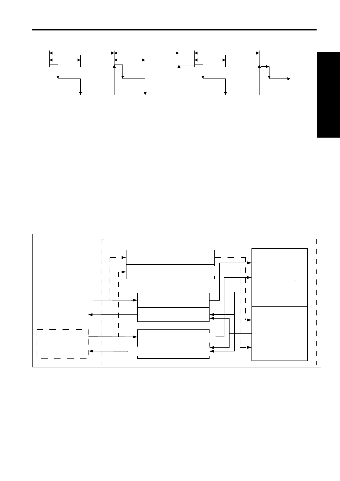
1.4 PROCESSING INPUT/OUTPUT SIGNAL 1.4 PROCESSING INPUT/OUTPUT SIGNAL
Processing of input/output signal is as the following figure. X signal of machine I/O interface and F signal of
Processing of input/output signal is as the following figure. X signal of machine I/O interface and F signal of
NC are separately input to input memories at machine side and NC side, and directly used by the first grade
NC are separately input to input memories at machine side and NC side, and directly used by the first grade
program; they separately input to synchronous input memories are used by the second. Output signals of the
program; they separately input to synchronous input memories are used by the second. Output signals of the
first and the second are separately output to output memories at NC side and machine side,and then separately
first and the second are separately output to output memories at NC side and machine side,and then separately
output to NC and I/O interface of machine
output to NC and I/O interface of machine
Signal states of the above-mentioned memories are displayed by diag no st i c inte rfa ce, an d th e diagn o s tic nu mber
Signal states of the above-mentioned memories are displayed by diag no st i c inte rfa ce, an d th e diagn o s tic nu mber
corresponds to address number of program.
corresponds to address number of program.
Book 1 Pro
rammin
PLC
NC
侧同步输入存储器
Syn. input memory at CN side
Syn. input memory at machine side
机床侧同步输入存储器
Grade one program
第一级程序
F
NC
侧输入存储器
Input memory at CN side
N C
Machine
机
床
G
X
Y
NC
侧输出存储器
Output memory at CN side
机床侧输入存储器
Input memory at machine side
Output memory at machine side
机床侧输出存储器
Grade two program
第二级程序
1.4.1 Processing Input Signal 1.4.1 Processing Input Signal
A:Input signal of grade one program: A:Input signal of grade one program:
Input memory at NC side is scanned every 8ms and stores F signal from NC, and the system directly use its state
Input memory at NC side is scanned every 8ms and stores F signal from NC, and the system directly use its state
when the first is executed.
when the first is executed.
B:Input signal of grade two program: B:Input signal of grade two program:
Input signal of the second is the one stored by the first. The first directly use F and X signal and so the input Input signal of the second is the one stored by the first. The first directly use F and X signal and so the input
Ⅰ-5
Page 14
signal of the second lags the first one and its max. lag time is runtime of one grade two program. signal of the second lags the first one and its max. lag time is runtime of one grade two program.
g
g
p
p
C:Difference of input signal states of the first and the second: C:Difference of input signal states of the first and the second:
Book 1 Pro
For the same input signal, its states are different in the first and the second when PLC reads input signals,
For the same input signal, its states are different in the first and the second when PLC reads input signals,
because the first reads input memories at NC side and machine side but the second reads the synchronous input
because the first reads input memories at NC side and machine side but the second reads the synchronous input
memory at NC side and ones at machine side. The input signal of the second lags behind that of the first and its
memory at NC side and ones at machine side. The input signal of the second lags behind that of the first and its
lag time is 8nms which should be noted.
lag time is 8nms which should be noted.
rammin
Example: Example:
GSK980TD Turning Machine CNC System
End of grade one
rogram
Fraction1:
0003~0005
Fraction1:
0006~0007
End of grade two
rogram
When the lag time is the first 8ms, X0001.0=1 and the system executes the first Y0001.0=1. When the system
starts to execute the second, X0001.0=1 inputs to the synchronous input memory and starts to execute the first
block of the fractional second.
When the lag time is the second 8ms, X0001.0=0 and the system executes the first one Y0001.0=1. And then the
system executes the second block of the fractional second but X0001.0 =1 which state is still the previous
synchronous input memory and Y0002.3=1 after execution.
1.4.2 Processing Input Signal
A:Signal to NC
PLC transmits output signal to the output memory at NC side every 8ms, and then directly outputs to NC.
B:Signal to machine
PLC transmits output signal to the output memory at machine side, and then directly outputs to memory every
2ms.
Ⅰ-6
Page 15

Chapter 1 Sequential Program
g
g
p
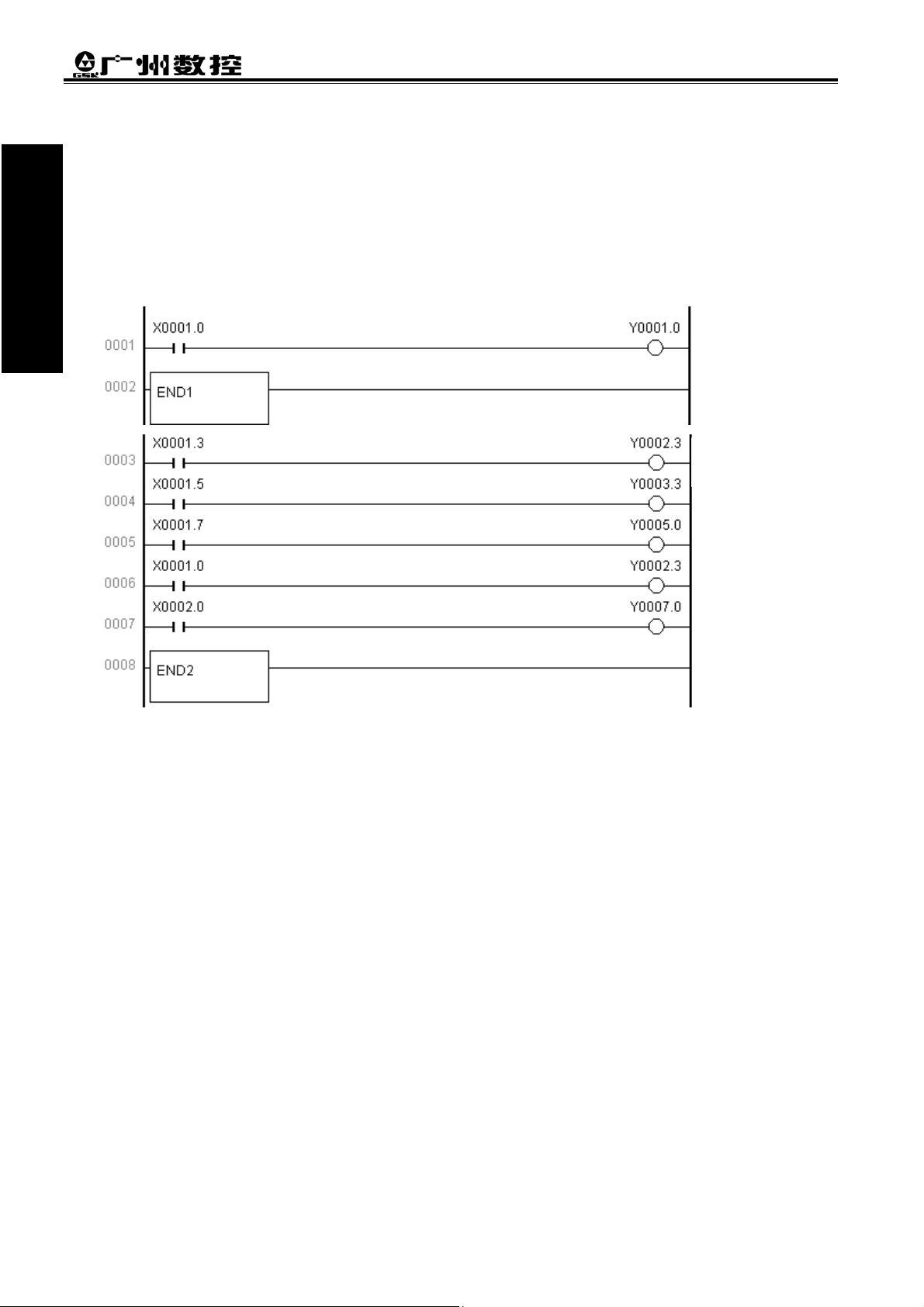
1.4.3 Synchronous Procession of Short Pulse Signal 1.4.3 Synchronous Procession of Short Pulse Signal
The first is used for processing the short pulse signal. When it is less than 8ms, namely when the system
The first is used for processing the short pulse signal. When it is less than 8ms, namely when the system
executes the first, the input signal state may be changed, which may execute programs by mistake.
executes the first, the input signal state may be changed, which may execute programs by mistake.
End of grade one
rogram
As above, X0001.3=0 is changed to X0001.3=1 after Y0002.3=1 is executed, and if the system executes the
next line of ladder and Y0003.3=1, at the moment Y0002.3=1 and Y0003.3=1. To avoid the above, process
synchronously the short pulse signal as follows:
Book 1 Pro
rammin
End of the first
grade program
After the program is executed synchronously and when X0001.3=1,Y0003.3=1,Y0002.3=0, X0001.3=0,
Y0002.3=1,and Y0003.3=0,but Y0003.3=1 or Y0002.3=1.
1.4.4 Interlock Signal
For safety, the signals must be employed with soft interlock in sequence control, and with hard interlock to relay
control circuit of power electric box at machine side at the same time. Because the hardware is failure, the
interlock is invalid in executing sequential program even if it is employed logically with soft interlock, which
can ensure the operator is not injured and the machine is prevented from damage.
1.5 EDITING SEQUENTIAL PROGRAM
Edit the sequential program from ladder which is composed of relay contacts, symbols and function instructions.
Logic relationship in ladder consists of sequential program which is edited by two methods: one is employed
with input to use program instructions and the other is with relay symbols by their corresponding contactor,
symbol and function instruction. Edit the sequential program employed with the ladder format instead of
mnemonic code language when the system is employed with the relay symbol.
In actual editing sequential program, use programming instruction or ladder to edit it according to PLC. In the
User Manual, the system is employed with ladder as follows:
Ⅰ-7
Page 16

1.5.1 Distributing Interface (Step 1)
g
g
GSK980TD Turning Machine CNC System
Book 1 Pr
The interfaces can be distributed after control target is defined and the corresponding input/output signal points
are counted. Refer to input/output interface signal list
o
1.5.2 Editing Ladder (Step 2)
rammin
Edit the software GSKCC.EXE by 980TD ladder to represent the required control operations of machine.
Counter, timer which are not done by relay symbol is represented by the specified function instructions. The
edited ladder is downloaded to CNC by serial.
1.5.3 Debugging Ladder (Step 3)
After the ladder is downloaded to 980TD, the ladder is debugged as follows:
A: emulator
Use one emulator instead of machine to debug it. Machine signal state is represented with switch ON/OFF,
and output signal state is done with indicat or ON/OFF. Observe if every indicator on the emulator is correct
when executing CNC.
B: CNC diagnosis
Observe if the diagnostic state of every signal is consistent with the function requirement when executing
CNC. Check the ladder by checking each function in order.
C: actual run
There may be an unexpected result in the actual debugging machine and so do preventive measures before
debugging.
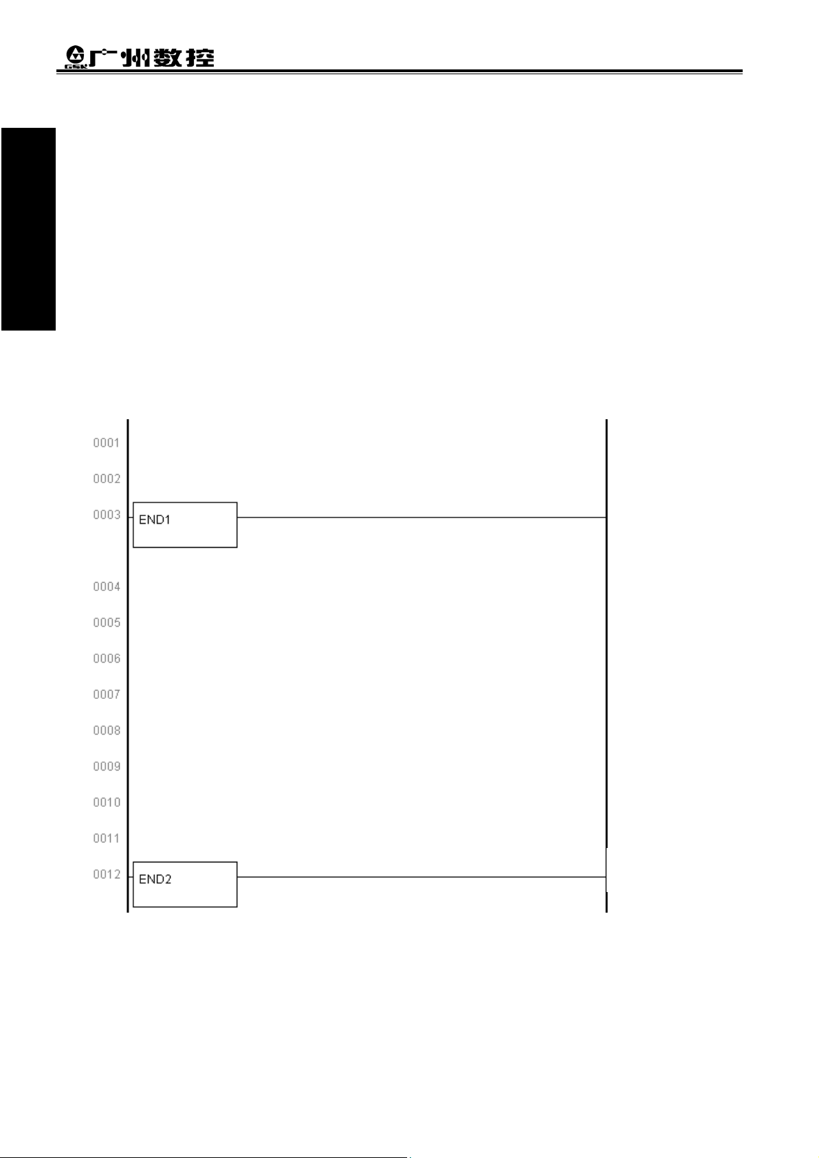
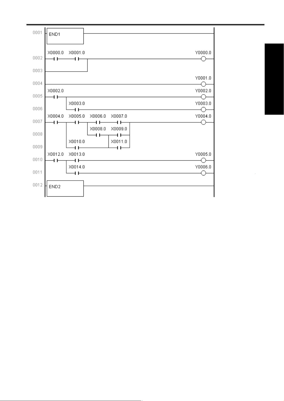
1.5.4 Program Editing Limit
In program, END1 and END2 are needed, which are taken separately as ending character of the first and the
second, and END1 must be before END2. The system only supports parallel output instead of multi grades
output and there are syntactic errors as follows:
Ⅰ-8
Page 17
Chapter 1 Sequential Program
p
g
g
End of grade one
rogram
Syntactic error:
0002~0003
Book 1 Pro
Syntactic error:
0004
Syntactic error:
0005~0006
Syntactic error:
0007~0009
Syntactic error:
0010~0011
rammin
Ⅰ-9
Page 18

Page 19

Chapter 2 Address
g
g
Chapter 2 ADDRESS
Addresses are used for distinguishing signals. Different addresses separately correspond to input/output signal
at machine side and CNC side, internal relay, counter, timer, holding relay and data list. An address number is
consisted of address type, address number and bit number as follows:
X 0001.6
Bit number
位号
地址号
Address number
地址类型
Address type
Address type: X, Y, R, F, G, K, A, T, DT, DC, C, D, L, P
Address number: decimal number to express one byte
Bit number: octal number, 0~7 separately expressing byte 0~7 bit of front address number
980TD PLC addresses are divided into fixed addresses and definable addresses. Signal definitions of the fixed
addresses cannot be changed and are defined by CNC; the definable addresses can be defined again by user
according to the actual requirements. Address types are as follows:
Address Explanation Range
X Machine→PLC X0000~X0029
Y PLC→machine Y0000~Y0019
F NC→PLC F0000~F0255
G PLC→NC G0000~G0255
R Intermediate relay R0000~R0999
D Data register D0000~D0999
C Counter C0000~C0099
T Timer T0000~T0099
DC Counter preset value register DC0000~DC0099
DT Timer preset value register DT0000~DT0099
A Information displaying request signal A0000~A0024
K Hold relay K0000~K0039
L Jump label L0000~L9999
P Subprogram label P0000~P9999
Note: address R900~R999, K30~39 are used for reserved area of CNC program instead of output relay.
Book 1 Pro
rammin
2.1 MACHINE→PLC ADDRESS(X)
980TD PLC X addresses are divided into two types,the first one is X0000.0~X0003.7,which are mainly
distributed to CNC XS40 and XS41 I/O interfaces, including fixed addresses and definable addresses,and the
second one is X0020.0~X0026.7,which are fixed addresses and mainly be distributed to input keys on operator
panel. Other addresses are reserved ones. The value range is 0 or 1.
Ⅱ-1
Page 20
g
g
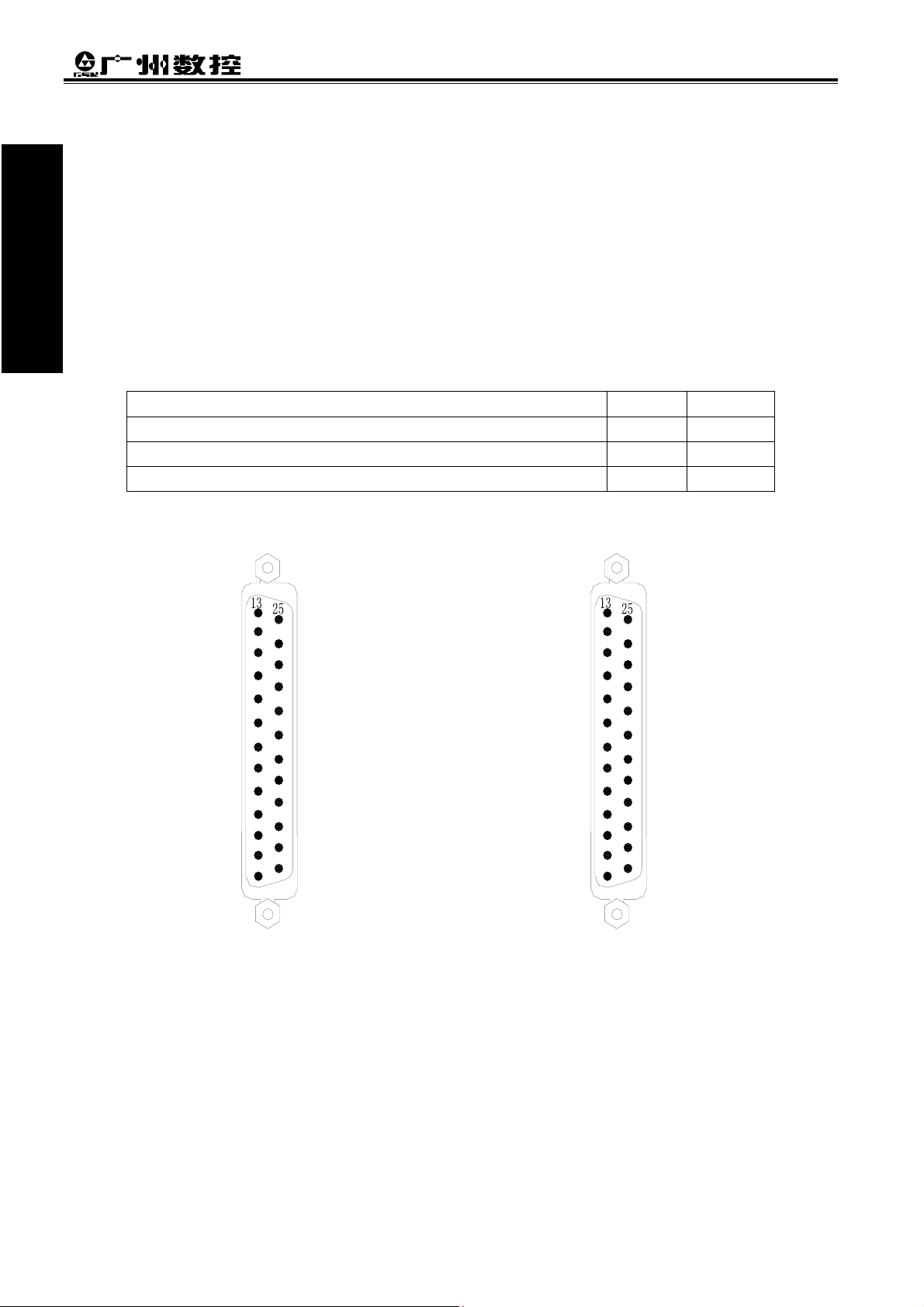
2.1.1 X Address in I/O Interface
GSK980TD Turning Machine CNC System
Book 1 Pro
rammin
13:Y0001.7
12:Y0001.6
11:+24V
10:X0000.5(ESP)
9: X0001.3(ZDEC)
8:X0001.1
7:X0001.4
6:X0001.6
5:X0001.7
4:X0000.0
3:X0000.1
2:X0000.2
1:X0000.3(XDEC)
z Address range: X0000.0~X0003.7 are separately distributed to CNC XS40 and XS41 I/O interface.
z Fixed address: X0000.3, X0000.5, X0001.3 separately corresponds to XDEC, ESP, ZDEC signal
Example: ESP signal is can be connected to X0000.5, CNC directly distinguishes signals on it and judge if there
Namely: CNC alarms to emergently stop when X0000.5 is 0;
CNC alarms to emergently stop when G8.4 is 0 by PLC control.
Emergent stop signal ESP X0000.5
Deceleration signal of machine reference point return in X direction XDEC X0000.3
Deceleration signal of machine reference point return in Z direction ZDEC X0001.3
z Definable address: their functions can be defined by user according to requirement and used for connecting
with external electric circuit and ladder. Distribution graph of X address in I/O interface is as follows:
which can be directly distinguished by CNC in CNC run.
is ESP signal; CNC alarms to emergently stop when G8.4 signal is valid by PLC control.
Input signal of fixed addresses
Signal Symbol Address
25:COM
24:COM
23:+24V
22:X0000.4
21:X0001.2
20:X0001.0
19:X0001.5
18:COM
17:COM
16:COM
15:COM
14:COM
13:X0002.1
12:X0002.2
11:+24V
10:X0002.3
9:X0002.5
8:X0003.1
7:X0003.3
6:X0003.6
5:X0003.5
4:X0003.7
3:X0003.0
2:X0002.7
1:X0002.0
25:COM
24:COM
23:+24V
22:X0002.4
21:X0002.6
20:X0003.2
19:X0003.4
18:COM
17:COM
16:COM
15:COM
14:COM
XS41(female) XS40(female)
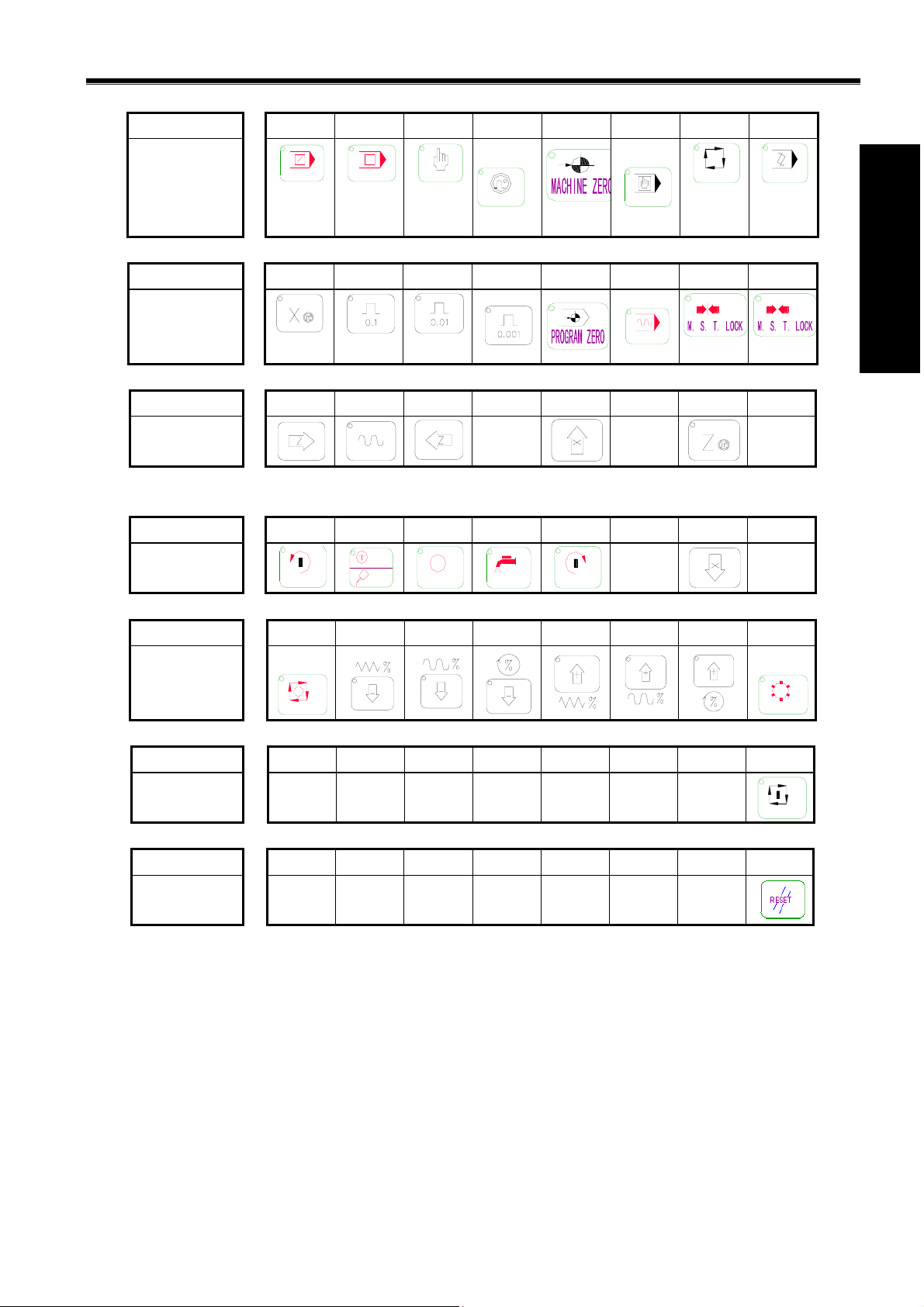
2.1.2 X Address on Operator Panel
Address range: X0020.0~X0026.0 are fixed addresses which correspond to press keys on operator panel and
which signal definitions cannot be changed by user.
Ⅱ-2
Page 21
Chapter 2 Address
g
g
Relationship between addresses and press keys is as follows:
X0020 7 6 5 4 3 2 1 0
SKIP
Key
SINGLE
JOG
MPG
AUTO
MDI
Book 1 Pro
EDIT
X0021 7 6 5 4 3 2 1 0
MST MST
Key
DRY
X0022 7 6 5 4 3 2 1 0
Key
X0023 7 6 5 4 3 2 1 0
Key
CCW
JOG
LUR.
STOP
COOLANT
CW
X0024 7 6 5 4 3 2 1 0
Key
PAUSE
X0025 7 6 5 4 3 2 1 0
Key
rammin
TOOL
RUN
X0026 7 6 5 4 3 2 1 0
Key
2.2 PLC→MACHINE ADDRESS(Y)
980TD-PLC Y address are divided into tw o: Y0 00 0.0~Y0003.7 are mainly distributed to CNC XS42 and XS39
I/O interfaces, including fixed address and definable address; Y0004.0~X0009.7 which are mainly distributed
to indicators on the operator panel. Other addresses are reserved ones. Their values are 0 or 1.
2.2.1 Y Address in I/O Interface
Address range: Y0000.0~Y0003.7 are separately distributed to CNC XS42 and XS39 I/O interfaces and their
signal definitions can be defined by user according to requirements to connect to external
Ⅱ-3
Page 22

g
g
Distribution graph of 980TD output interfaces address is as follows:
Book 1 Pro
rammin
electric circuit and ladder.
1:Y0003.0
2:Y0002.7
3:Y0002.6
4:Y0002.2
5:Y0002.0
6:Y0002.1
7:Y0003.2
8:Y0003.3
9:Y0003.4
10:Y0003.5
11:Y0003.6
12:Y0003.7
13:+24V
14:Y0003.1
15:Y0002.5
16:Y0002.4
17:Y0002.3
18:COM
19:COM
20:COM
21:COM
22:COM
23:COM
24:COM
25:+24V
XS42(male)
GSK980TD Turning Machine CNC System
1:Y0000.0
2:Y0000.2
3:Y0000.4
4:Y0000.6
5:Y0001.0
6:Y0001.1
7:Y0001.2
8:Y0001.3
9:Y0001.4
10:Y0001.5
11:X0000.6
12:X0000.7
13:+24V
XS39(male)
14:Y0000.1
15:Y0000.3
16:Y0000.5
17:Y0000.7
18:COM
19:COM
20:COM
21:COM
22:COM
23:COM
24:COM
25:+24V
2.2.2 Y Addresses on Operator Panel
Address range: Y0004.0~Y0009.0 are fixed addresses which correspond to indicators on the operator panel,
and which signal definitions cannot be changed by user. Relationship corresponding to each state indicator is
referred to Appendix2: Output signal(Y).
2.3 PLC→NC ADDRESS(G)
Address range: G0000.0~G0255.7, value range: 0 or 1. Refer to Appendix3: G, F signals about definitions of
address signals.
2.4 NC→PLC ADDRESS(F)
Address range: F0000.0~F0255.7, value range: 0 or 1. Refer to Appendix3: G, F signal about definitions of
address signals.
2.5 INTERNAL RELAY ADDRESS
Address range: R0000.0~R0999.7, value range: 0 or 1. They are zero after CNC is switched on.
Ⅱ-4
Page 23

Chapter 2 Address
g
g
Address
number
R0000
R0001
R0899
R0900
R0999
7 6 5 4 3 2 1 0
Definable
addresses
NC
2.6 INFORMATION DISPLAYING REQUEST ADDRESS(A)
Address range: A0000.0~A00024.7 and they are zero after CNC is switched on.
Address
number
A0000
A0001
A0024
7 6 543210
Book 1 Pro
rammin
2.7 HOLD RELAY ADDRESS(K)
The address area is used for hold relay and setting PLC parameters and data are saved after the system is
switched off. Address range: K0000.0~K0039.7, value range: 0 or 1.
Address
number
K0000
K0001
K0029
K0030
K0039
7 6 5 4 3 2 1 0
Definable
addresses
NC
Ⅱ-5
Page 24

GSK980TD Turning Machine CNC System
g
g
2.8 COUNTER ADDRESS(C)
Book 1 Pro
The address area is used for storing current counting value of counter and data are saved after the system is
switched off. Address range: C0000~C0099, value range: 0~21,4748,3647.
rammin
Address
number
C0000
C0001
C0099
31 30 29 28
2.9 COUNTER PRESET VALUE ADDRESS(DC)
3 2 1 0
The address area is used for storing preset value of counter and data are saved after the system is switched off.
Address range: DC0000~DC0099, value range: 0~21,4748,3647.
Address
number
DC0000
DC0001
DC0099
31 30 29 28
3 2 1 0
2.10 TIMER ADDRESS(T)
The address area is used for storing current value of timer and T0000~T0079 are zero after the system is
switched on.T0080~T0099 are saved after it is switched off. Value range: 0~21,4748,3647.
Address
number
T0000
T0001
T0099
31 30 29 28
3 2 1 0
Ⅱ-6
Page 25

Chapter 2 Address
g
g
2.1 1 TIMER PRESET VALUE ADDRESS(DT)
The address area is used for storing preset value of timer and data are saved after the system is switched off.
Address range: DT0000~DT0099 and value range: 0~21,4748,3647.
Address
number
DT0000
DT0099
31 30 29 28
3 2 1 0
2.12 DATA LIST ADDRESS(D)
D0000~D0299 are zero when CNC is switched on. D0300~D0999 are saved after it is switched off. Value
range: 0~255.
Address
number
D0000
D0001
D0299
D0300
D0999
7 6 5 4 3 2 1 0
Book 1 Pro
rammin
2.13 LABEL ADDRESS(L)
It is used for specifying jump target label in JMPB and LBL label.
Range: L0~L9999
2.14 SUBPROGRAM NUMBER(P)
It is used for specifying the target subprogram number to call in CALL and subprogram number in SP.
Range: P0000~P9999
Ⅱ-7
Page 26

Page 27

Chapter 3 PLC Basic Instructions
g
g
Chapter 3 PLC BASIC INSTRUCTIONS
Basic instructions are used for editing sequential programs and executing 1-bit operation. There are basic instructions
for GSK980TD PLC as follows:
Instruction
name
LD Read normally-open contact X, Y, F, G, R, K, A
LDI Read normally-closed contact X, Y, F, G, R, K, A
OUT Output coil Y, G, R, K, A
AND Normally-open contact in series X, Y, F, G, R, K, A
ANI Normally-closed contact in series X, Y, F, G, R, K, A
OR Parallel normally-open contact X, Y, F, G, R, K, A
ORI Parallel normally-closed contact X, Y, F, G, R, K, A
ORB Parallel series circuit block
ANB Parallel circuit block in series
3.1 LD,LDI,OUT INSTRUCTION
Function Component
Book 1 Pro
rammin
● Mnemonic code and function
Mnemonic code Function Ladder symbol
LD Read normally-open contact
LDI Read normally-closed contact
OUT Output coil
● Instruction explanation
A: LD, LDI are used for connecting contact to bus bar. Each one can combine with instruction ANB and can be
used at starting point of branch.
B: OUT is used for driving output relay, internal relay coil instead of input relay.
C: Parallel instruction OUT can be continuously used.
● Programming example
Program explanation:
When X0002.1 is 1, the system outputs Y0003.7
When F0100.3 is 0, the system outputs G0120.0
Ⅲ-1
Page 28
3.2 AND, ANI INSTRUCTION
g
g
Bo
● Mnemonic code and function
ok 1 Pro
Mnemonic code Function Ladder symbol
GSK980TD Turning Machine CNC System
ram i
m
n
● Instruction explanation
AND, ANI can connect one contact in serial. There can be many contacts in serial and the instructions can be
used many times.
● Programming example
Program explanation:
Use X0002.1,
Use F0100.3 and X0002.1 in series
Use X0008.6, and F0100.3 and X0002.1 in series
If X0002.1=1, X0008.6=1 and F0100.3 is 0, the system outputs Y0003.7.
AND Normally-open contact in series
ANI Normally-closed contact in series
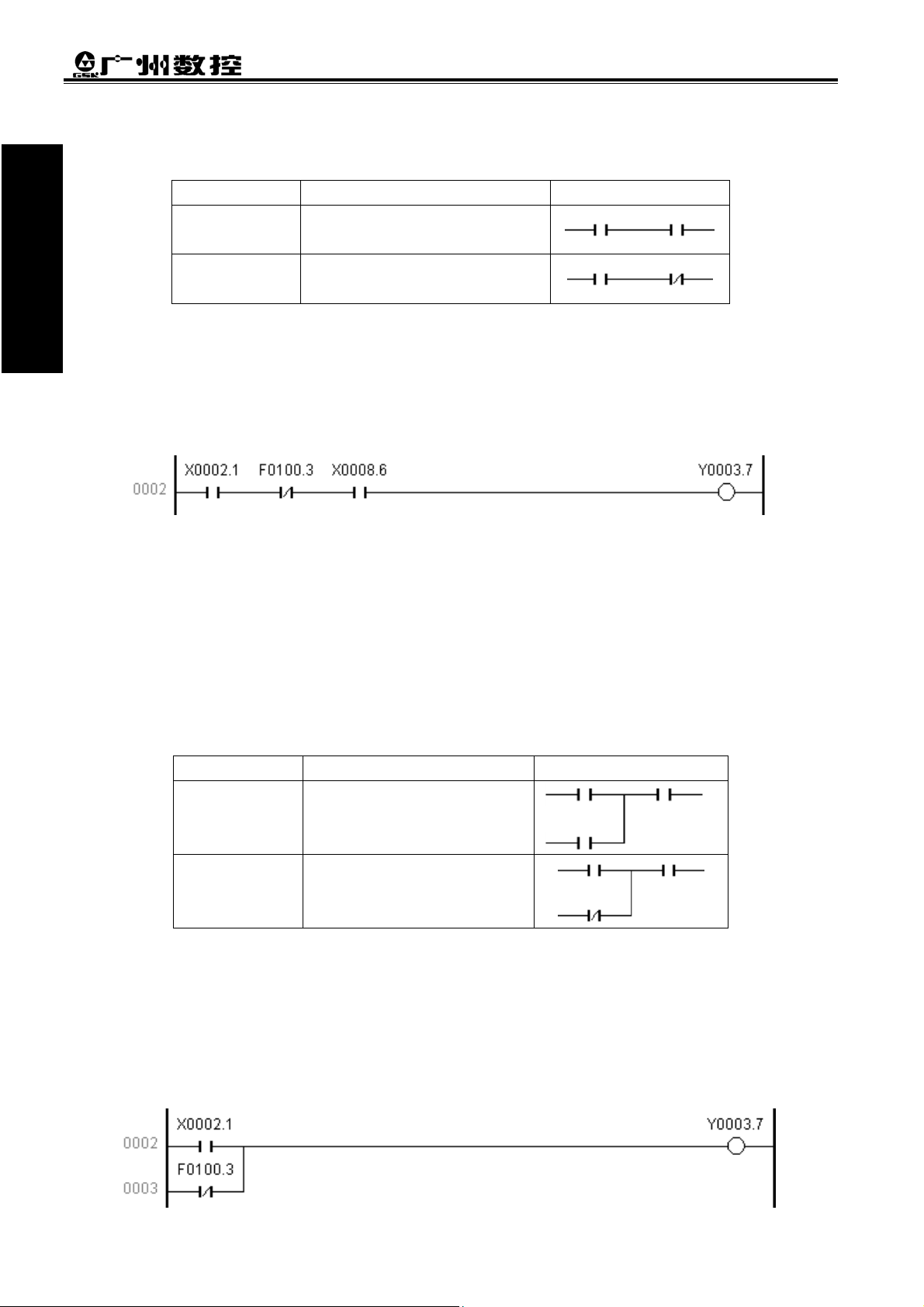
3.3 OR, ORI INSTRUCTION
● Mnemonic code and function
Mnemonic code Function Ladder symbol
OR Parallel normally-open contact
ORI Parallel normally-closed contact
● Instruction explanation
A: OR, ORI can be connected to one contact in parallel. When more than two contacts are connected in series
and the serial loop is connected with other loop in parallel, the system should use ORB.
B: The system executes OR, ORI from its current step with LD, LDI in parallel.
● Programming example
Ⅲ-2
Page 29

Chapter 3 PLC Basic Instructions
g
g
N
Program explanation: Program explanation:
Use X0002.1 Use X0002.1
Use F0100.3 and X0002.1 in series Use F0100.3 and X0002.1 in series
If X0002.1=1, and F0100.3 is 0, the system outputs Y0003.7. If X0002.1=1, and F0100.3 is 0, the system outputs Y0003.7.
Book 1 Pro
3.4 ORB INSTRUCTION 3.4 ORB INSTRUCTION
●Mnemonic code and function ●Mnemonic code and function
Mnemonic code Mnemonic code Function Function Ladder symbol Ladder symbol
ORB Parallel series circuit block
● Instruction explanation
A: Serial loop block is defined to its loop combined by more than contacts in series. When the serial loop is
connected in parallel, starting point of branch uses LD and its end point uses ORB.
B: ORB is sole instruction without address.
● Programming example
ode
rammin
Program explanation:
As above figure, there are three branches(0002,0003,0004) from left bus line to node, and 0002 and 0003 are
serial circuit blocks. There is parallel serial circuit block between bus line and node or among nodes, the
following ending of branch use ORB except for the first one. Use OR instruction if the branch 0004 is not serial
circuit block.
ORB and ANB are instructions without operation function, representing or, and relationship among circuit
blocks.
3.5 ANB INSTRUCTION
●Mnemonic code and function
Mnemonic code Function Ladder symbol
ANB Parallel circuit block in series
● Instruction explanation
A: Use ANB when the branch loop is serially connected with the previous loop. Use LD, LDI at the starting
Ⅲ-3
Page 30

point of branch, and use ANB to serially connect with the previous loop. point of branch, and use ANB to serially connect with the previous loop.
g
g
B: ANB is sole instruction without address. B: ANB is sole instruction without address.
Book 1 Pro
● Programming example ● Programming example
rammin
GSK980TD Turning Machine CNC System
Block 1
Program explanation:
As above ladder, ORB represents the parallel serial circuit block in block 2 and ANB represents block 1 and 2 in
series.
Block 2
Ⅲ-4
Page 31

Chapter 4 PLC Function Instructions
g
g
Chapter 4 PLC FUNCTION INSTRUCTIONS
Some functions are completed by function instructions instead of basic ones. The function instructions in the
system are as follows:
Instruction
name
END1 End of grade one program ROTB Binary rotation control
END2 End of grade two program DECB Binary decoding
SET Set CODB Binary code conversion
RST Reset JMPB Program jumping
CMP Comparative set LBL Program jumping label
CTRC Counter CALL Subprogram calling
TMRB Timer SP Start of subprogram
MOVN Binary Data copy SPE End of subprogram
PARI Parity check DIFU Ascending edge set
ADDB Binary data adding DIFD Descending edge set
SUBB Binary data subtracting MOVE And
ALT Alternative output
Function Instruction
name
Function
Book 1 Pro
rammin
4.1 END1(END of GRADE ONE PROGRAM)
● Instruction function
There must be END1 in the sequential program one time, located at the end of grade one program. It should be
located at the home of the second when there is no grade one program.
● Ladder format
4.2 END2(END of GRADE TWO PROGRAM)
● Instruction function
There must be END2 at the end of grade two program which representing end of grade two program.
● Ladder format
Ⅳ-1
Page 32

4.3 SET
g
g
Bo
● Instruction function
ok Pro
1
Specified address is set to 1.
● Ladder format
ramm
GSK980TD Turning Machine CNC System
in
● Control condition
ACT =0:add.b is reserved.
=1:add.b is set to 1.
● Relative parameter
add.b:set address bit,which can be a contact or output coil, and add is Y, G, R, K or A.
● Program example:
Explanation: When X0002.1 is 1, R0002.0 is set to 1; when X0002.1 is 0, R0002.0 is reserved.
4.4 RST(RESET)
● Instruction function
Specified address is set to 0.
● Ladder format
● Control condition
ACT =0:add.b is reserved.
=1:add.b is set to 0.
● Relative parameter
add.b:reset address bit ,which can a contact or output coil ,and add is Y, G, R, K or A.
● Program example:
Explanation: When X0002.1 is 0, R0002.0 is reserved; when X0002.1 is 1, R0002.0 is set to 0.
Ⅳ-2
Page 33

Chapter 4 PLC Function Instructions
g
g
4.5 CMP(BINARY COMPARATIVE SET)
● Instruction function
Compare two binary data and output its result.
● Ladder format
● Control condition
ACT =0:add.b is reserved.
=1: compare S1, S2 and output the result as follows:
add.(b+2) add.(b+1) add.(b+0)
S1>S2 0 0 1
S1=S2 0 1 0
S1<S2 1 0 0
● Relative parameter
Length: specify data length, when it is set to 1, 2, 4, the corresponding data length is 1byte, 2bytes,4 bytes.
S1, S2: compare source data 1 with data 2, and the comparative result can be constant or address number(it is not
address bit. For example: add.b is illegal.). Address number is R, X, Y, F, G, K, A, D, T, C, DC and DT.
add.b:it is the comparative result and can be R, Y, G, K and A.
● Relative operation information register:
R900 overflow
● Program example:
Negative Zero
Book 1 Pro
rammin
Explanation: When X0002.1 is 0, the system does not compare the data and R0300.0 is reserved;
When X0002.1 is 1, the system compares the data as follows:
R0300.2 R0300.1 R0300.0
R0100>R0200 0 0 1
R0100=R0200 0 1 0
R0100<R0200 1 0 0
Ⅳ-3
Page 34

4.6 TMRB(TIMER) 4.6 TMRB(TIMER)
g
g
Book 1 Pro
●
Instruction function ● Instruction function
Delay connecting the timer. Delay connecting the timer.
●
Ladder format ● Ladder format
rammin
● Control condition
ACT =0:reset TIMER and add.b.
=1:TIMER times from 0, and add.b=1 when TIMER reaches the preset time.
Logic relation is as follows:
● Relative parameter
TIMER: timer number, range: T0000~T0099.
TIME: timing constant or data register with DT in front. DT range is from 0 21,4748,3647(ms) .
add.b:it is timer output address and can be R, Y, G, K and A.
TIMER is executed every 8ms and timing with 8ms as unit.
● Program example:
ACT
add.b
GSK980TD Turning Machine CNC System
TIME
Explanation: When X0002.1 is 0, T0002 and R0300.0 are 0;
When X0002.1 is 1, T0002 starts to count, and R0300.0 is set to 1 after it reaches the time set by
DT0004.
Ⅳ-4
Page 35

Chapter 4 PLC Function Instructions
g
g
m
4.7 CTRC(BINARY COUNTER) 4.7 CTRC(BINARY COUNTER)
● Instruction function ● Instruction function
Data in the counter is binary and the functions of CTRC is as follows: Data in the counter is binary and the functions of CTRC is as follows:
A: reset counter: it resets count value and the system outputs the corresponding signal when the count value
A: reset counter: it resets count value and the system outputs the corresponding signal when the count value
reaches the resetting count value.
reaches the resetting count value.
B: ring counter:input the count value signal when the counter reaches the reset value, and count again the
B: ring counter:input the count value signal when the counter reaches the reset value, and count again the
counter reset to initial value.
counter reset to initial value.
C: adding/subtracting counter: bit bidirectional counter used for addition and subtraction. C: adding/subtracting counter: bit bidirectional counter used for addition and subtraction.
D: initial value selection: it can be 0 or 1. D: initial value selection: it can be 0 or 1.
● Ladder format ● Ladder format
Book 1 Pro
rammin
● Control condition
ACT is at ascending edge:
Adding: COUNTER counts from its setting initial value, adds the count one time when it reaches the
ascending edge, and O_add.b =1 when it reaches the reset count value. O_add.b =0 when
COUNTER is less than NCOUNT; COUNTER resumes and starts to count and O_add.b =0 when
it reaches the ascending edge again.
Subtracting: COUNTER subtracts from its setting initial value, subtracts the count one time when it
reaches the ascending edge, and O_add.b =1 when it reaches the reset count value. O_add.b
=0 when COUNTER is more than NCOUNT; COUNTER resumes and starts to count and
O_add.b =0 when it reaches the ascending edge again.
ACT=0:
COUNTER and O_add.b are reserved.
● Relative parameter
Data format:
R_add.b :when it is 1 whatever ACT is , COUNTER=CN0,O_add.b =0. R_add can be X, Y, G, F, R, K, A.
COUNTER: specify the counter number( Cxxx, xxxx is digit(0~99),
0 0 CN0 U/D
Specify adding/subtracting count
0:adding count and counting from 0
1:subtracting count and counting fro
reset value
Specify the counter initial value
0:count from 0
1:count from 1
Ⅳ-5
Page 36

NCOUNT: it is counter preset value(constant) and also can be data register beginning with DC. If it is constant,
g
g
Book Pro
1
O_add.b: when it reaches to the count value, the output is 1 and O_add can be R, Y, G, K and A.
● Program example:
rammin
Explanation: When R0100.0 is 1, C0001=0 and R0500.0=0;
When R0100.0 is 0, X0002.1 reaches the drift up one time, C0001 adds the count one time, and
When X0002.1 reaches the drift up again, C0001 is reset to 0 and start to count, and R0500.0 is
GSK980TD Turning Machine CNC System
its value is 0~21,4748,3647.
R0500.0 is 1 if the count reaches 10.
reset to 0.
4.8 MOVN(BINARY DATA COPY)
● Instruction function
Transmit data at source address or specified binary data to destination address.
● Ladder format
● Control condition
ACT =0:ADD-D is reserved.
=1:copy the value in ADD-S or constant CON to ADD-D
● Relative parameter
Length : it is the copy data(1, 2, 4 byte).
ADD-S/CON: it is initial byte of source data address or constant, and its address number is R, X, Y, F, G, K, A,
D, T, C, DC and DT.
ADD-D: it is initial byte of target address, and its address number is R, Y, G, K, A, D, T, C, DC, DT.
● Program example:
Explanation:R0100 value is transmitted to G0043 when X0003.3 is 1.
Ⅳ-6
Page 37

Chapter 4 PLC Function Instructions
g
g
4.9 DECB(BINARY ENCODING)
● Instruction function
DECB can decode the binary code data. When there is the same one between one of 8 successive data and the
code data, the corresponding output data is 1; when there is no the same one, the output data is 0. DECB is used
for encoding data of M or T function.
● Ladder format
● Control condition
ACT =0:reset the 8 data bits of ADD2. ADD2.
=1:compare the content value of decoding address(ADD1) with 8 successive data beginning with DATA.
When the value of ADD1 is equal to one of 8 data and the output address (ADD2)
bit which sequence number is that of equal data in these 8 data is set to 1.
● Relative parameter
Length:specify the length(1, 2, 4) of ADD1.
ADD1: it is initial address of encoding and the address number is R, X, Y, F, G, K, A, D, T, C, DC and DT.
.
DATA: reference value of comparative constant.
ADD2: output comparative result. Its address number is R, Y, G, K and A.
● Program example:
‘
s corresponding
Book 1 Pro
rammin
X0003.3=1:
When F0010=8,R0010.0=1;
When F0010=9,R0010.1=1;
…………………………
When F0010=15,R0010.7=1
4.10 CODB(BINARY CODE CONVERSION)
● Instruction function
The instruction is used for binary code conversion.
● Ladder format
Ⅳ-7
Page 38

Book 1 Pro
g
g
● Control condition
ACT =0:ADD2 is reserved.
rammin
● Relative parameter
● Program example:
=1:value of conversing input data addre ss(ADD 1) is taken as list number of conversion list, from which
Converting input data
Address ADD1
Length1: binary data length and output address length of conversion data in conversion list, 1-1, 2-2, 4-4 byte.
Length2:conversion length, 1-2, 2-4, 3-8, 4-16, 5-32, 6-64, 7-128, 8-256.
ADD1:input address of conversion data. Its address has data with only one byte. Its address is R, X, Y, G, F,A,
K, and D.
ADD2:output address of conversion data and its address is R, Y, G, K and D.
GSK980TD Turning Machine CNC System
the conversion data corresponding to the list number is transmitted to output address(ADD2) of
conversion data.
Conversion data list
Converting input data
Number Value
……..
……….
Address ADD2
D2
Example
X0003.3=1:
X0003.3=1, R0100=0:R0200=1
X0003.3=1, R0100=1:R0200=2
X0003.3=1, R0100=2:R0200=3
X0003.3=1, R0100=3:R0200=4
Conversion data list
Number
Value
4 003
Ⅳ-8
Page 39

Chapter 4 PLC Function Instructions
g
g
4.11 JMPB(PROGRAM JUMPING)
● Instruction function
Immediately jump the program to the position set by label with characteristics as follows: jump instructions can
use the same label; forbid jumping END1 and END2; forbid jumping subprogram; jump forward or backward.
● Ladder format
Book 1 Pro
rammin
● Control condition
ACT =0:do not jump and execute the next instruction following JMPB.
=1:execute the next instruction following the label after jumping to the specified label.
● Relative parameter
Lx :specify the jumping target label, label number must be specified with beginning L address t and it can
specify one of L1 to L999.
● Program example:
Explanation: When X0003.3 is 1, the program jumps 0003 and orderly executes from 0004; when X0003.3 is 0, the
system orderly executes the program from 0003.
4.12 LBL(PROGRAM JUMPING LABEL)
● Instruction function
Specify one label in ladder, namely jumping target position specified by JMPB. One Lx is only specified one
time by LBL.
● Ladder format
Ⅳ-9
Page 40

● Relative parameter
g
g
Book 1 P
Lx :specify jumping target label. The label number is specified with beginning L address t and it can specify
one of L1 to L999.
ro
4.13 CALL(SUBPROGRAM CALLING)
ra minm
● Instruction function
Call the specified subprogram with characteristics as follows: call instructions can use the same subprogram;
call instruction can be embedded; cannot call a subprogram in grade one program; a subprogram is edited
following END2.
● Ladder format
● Control condition
ACT =0:execute the next instruction following CALL.
=1:call subprogram which number is specified.
● Relative parameter
Px :specify the called subprogram label, its label number is specified with beginning P address and it can
specify one of from P1 to P999.
GSK980TD Turning Machine CNC System
4.14 SP(START of SUBPROGRAM), SPE(END of SUBPROGRAM)
● Instruction function
SP is to create a subprogram which number is used for subprogram name ,and SPE is taken as end symbol of
program ,when SPE is executed, the main program will be returned to. SP and SPE are together used for
specifying the subprogram range ,and the subprogram must be edited following END2.
● Ladder format
● Relative parameter
Px :specify the call subprogram label, its label number is specified with beginning P address and it can specify
one of P1 to P999.
Ⅳ-10
Page 41

● Program example:
g
g
Chapter 4 PLC Function Instructions
Book 1 Pro
rammin
Explanation: When X0003.3 is 1, the program calls P0000 subprogram and jumps to execute 0006, and the
system orderly executes the program from 0003 after executing 0009.
When X0003.3 is 0, the system does not call P0000 subprogram and orderly executes
subprograms from 0003.
4.15 ROTB(BINARY ROTATION CONTROL)
● Instruction function
The instruction is used for rotation control, such as toolpost, rotary worktable. Its functions are as follows: to
select rotation direction of short path ,to count steps from current position to target position ;or to count steps
from the previous one of current position to the previous one of target position ,to count the position number of
the previous one of target position.
● Ladder format
Ⅳ-11
Page 42

GSK980TD Turning Machine CNC System
g
g
p
N
● Control condition ● Control condition
ACT =0:do not execute instructions, and E_add and O_add.b are reserved. ACT =0:do not execute instructions, and E_add and O_add.b are reserved.
Book 1 Pro
● Relative parameter ● Relative parameter
Format: Format:
rammin
CNT :centigrade position number of swivel table. CNT :centigrade position number of swivel table.
length :specify the length of W_add ,D_add and E_add(1, 2, 4 byte). length :specify the length of W_add ,D_add and E_add(1, 2, 4 byte).
W_add :it is current position address used for storing current position number. Its address W_add :it is current position address used for storing current position number. Its address
D_add :it is target position address used for storing target position number. Its address number is R, X, Y, F, G,
D_add :it is target position address used for storing target position number. Its address number is R, X, Y, F, G,
E_add :it is used for counting the result output address. Its address number is R, Y, G, K, A, D, DC and DT. E_add :it is used for counting the result output address. Its address number is R, Y, G, K, A, D, DC and DT.
O_add.b :it is used for outputting the rotary direction to ensure adding position number of swivel table is
O_add.b :it is used for outputting the rotary direction to ensure adding position number of swivel table is
● Program example: ● Program example:
Example: The current position corresponds to No. 1 tool selection when the toolpost is rotating. Example: The current position corresponds to No. 1 tool selection when the toolpost is rotating.
=1:execute instruction and output its result to E_add and O_add.b. =1:execute instruction and output its result to E_add and O_add.b.
Count position number or steps
0:Count position number
1:Count ste
number is R, X, Y, F, G , K, A, D, DC and DT. number is R, X, Y, F, G , K, A, D, DC and DT.
K, A, D, DC and DT.
K, A, D, DC and DT.
positive(FOR); if it is subtracting, its direction is negative(rev). When O_add.b=0, the rotary
positive(FOR); if it is subtracting, its direction is negative(rev). When O_add.b=0, the rotary
direction is positive; O_add.b=1, it is negative. Its address number is R, Y, G, K and A.
direction is positive; O_add.b=1, it is negative. Its address number is R, Y, G, K and A.
Current position
1
2
Position D
Position C
3
egative
4
5
6
7
Count position Count position
0:Count target position 0:Count target position
1:Count the position before target 1:Count the position before target
Short circuit selection
0:No selection. Positive rotation,i.e. O_add.b=0
1:Selection. Its direction is defined by specifics
Specify the initial number of swivel table
0:Position number of swivel table is from 0
1:Position number of swivel table is from 1
12
Positive
9
8
Position B
11
10
s
Position A
Ⅳ-12
Page 43

Chapter 4 PLC Function Instructions
g
g
Count the previous position number before target position when the toolpost rotates in short circuit. When the
current position number R0007=1 and centigrade position number of swivel table CNT=12, X0003.3=1:
When F0026=10 and the target position is A, R0027=11,R0037.0=1
When F0026=8 and the target position is B,R0027=9 ,R0037.0=1
When F0026=5 and the target position is C,R0027=4 ,R0037.0=0
When F0026=3 and the target position is D,R0027=2 ,R0037.0=0
4.16 PARI(PARITY CHECK)
Book 1 Pro
rammin
● Instruction function
Check parity of input data ,which is 1 byte(8 bits)
● Ladder format
● Control condition
ACT=1: Execute the parity check for input data. If the input data is inconsistent with the one specified by O_E,
Addr_Err.b is 1; otherwise, Addr_Err.b is 0
ACT=0: Do not execute instructions and Addr_Err.b is reserved.
● Relative parameter
O_E =0:number of “1” in put data is even
=1:number of “1” in put data is old number
Addr_Rst.b:when it is 1, Addr_Err.b is reset to 0 and its address is X, Y, G, R, F, A, K and K. 为 1 时,
Addr_Err.b .
Addr_In :it is the input data address and its address is X, Y, G, R, F, A, K and D.
Addr_Err.b :it is the output address of check result and its address is Y, G, R, A and K.
● Program example:
Ⅳ-13
Page 44

Book 1 Pro
g
g
Explanation: When X0003.3 is 1, the system executes PARI instruction, O_E=0000 to execute the even check.
When R0010.0 is 1, R0030.0 is reset to 0 and the system does not execute the check. When
rammin
R0010.0 is 0, it does. When there is an even number for “1”in R0020, R0030.0 is 0. When there is
an odd number for “1”in R0020, R0030.0 is 1.
4.17 ADDB(BINARY DATA ADDING)
● Instruction function
Add binary data
● Ladder format
GSK980TD Turning Machine CNC System
● Control condition
ACT=1: the system executes Addr_Out=AGD1+AGD2. If the operation is mistake, Addr_Err.b is 1; otherwise,
it is 0.
ACT=0: the system does not execute instruction, Addr_Out and Addr_Err.b are reserved.
● Relative parameter
Length :1-1,2-2,4-4 byte.
AGD1 :it is a summand and can be constant or address. Its address number is R, X, Y, F, G, A, K, D, T, C, DC
and DT.
AGD2 :it is addend and can be constant or address. Its address number is R, X, Y, F, G, A, K, D, T, C, DC and
DT.
Addr_Rst.b:when it is 1, Addr_Err.b is reset to 0 and Addr_Out is reserved. Its address number is R, X, Y, F, G,
A and K.
Addr_Out :it is the output data address of run result. Its address is Y, G, R, A, K, DC, DT, D, C, and T.
Addr_Err.b:it is the output address of mistake operation result and its address is Y, G, R, A and K.
● Relative operation information register
R900 overflow negative zero
● Program example:
Ⅳ-14
Page 45

Chapter 4 PLC Function Instructions
g
g
Explanation: When X0003.3=1, the system executes ADDB instruction. When R0040=R0010+R0020 and if the
operation is mistake, R0050.0 is 1, otherwise it is 0. When R0030.0 is 1, R0040 is reserved and R0050.0 is reset to 0.
4.18 SUBB(BINARY DATA SUBTRACTING)
● Instruction function
Subtract the binary data.
● Ladder format
Book 1 Pro
rammin
● Control condition
ACT=1: the system executes Addr_Out= MIND-SUBD. If the operation is mistake, Addr_Err.b is 1; otherwise,
it is 0.
ACT=0: the system does not execute instruction, and Addr_Out and Addr_Err.b are reserved.
● Relative parameter
Length :1-1,2-2,4-4 byte.
MIND :it is minend and can be constant or address. Its address number is R, X, Y, F, G, A, K, D, T, C, DC and
DT.
SUBD :it is subtrahend and can be constant or address. Its address number is R, X, Y, F, G, A, K, D, T, C, DC
and DT.
Addr_Rst.b:when it is 1, Addr_Err.b is reset. Its address number is R, X, Y, F, G, A and K.
Addr_Out:it is the output data address of run result. Its address is Y, G, R, A, K, DC, DT, D, C, and T.
Addr_Err.b:it is the output address of mistake operation result and its address is Y, G, R, A and K.
● Relative operation information register
R900 Overflow negative Zero
Note: the reset has no related to R900.
● Program example:
Ⅳ-15
Page 46

GSK980TD Turning Machine CNC System
g
g
Book 1 Pro
rammin
Explanation: When X0003.3=1, the system executes SUBB instruction. When R0040=R0010-R0020 , and if the
operation is mistake, R0050.0 is 0, otherwise it is 1. When R0030.0 is 1, R0040 is reserved and
R0050.0 is reset to 0.
4.19 DIFU(ASCENDING EDGE SET)
● Instruction function Set the output signal to 1 when the ascending edge of input signal is valid.
● Ladder format
● Control condition
Input signal ACT: the output signal is set to 1 at the ascending edge of ACT(0->1).
Output signal Add.b: when it is executed, one scanning period of Add.b in ladder is 1.
● Relative parameter
add.b :it is the operation result output address and its address is Y, G, R, A and K.
● Program example
Explanation: R0040.0 output is 1 when X0003.3 reaches the ascending edge.
4.20 DIFD(DESCENDING EDGE SET)
● Instruction function
Set the output signal to 1 when drift down of input signal is valid.
● Ladder format
● Control condition
Input signal ACT: the output signal is set to 1 at the descending edge of ACT(1->0).
Ⅳ-16
Page 47

Chapter 4 PLC Function Instructions
g
g
Output signal Add.b: when it is executed, one scanning period of Add.b in ladder is 1.
● Relative parameter
Add.b :it is the operation result output address and its address is Y, G, R, A and K.
● Program example:
Book 1 Pro
rammin
Explanation: R0040.0 output is 1 when X0003.3 reaches the descending edge.
4.21 MOVE(AND)
● Instruction function
Logic multiply and input data execute logic and operation, and then the system output the result to the specified
address.
● Ladder format
● Control condition
ACT=1: Logic multiply (HIGH4、LOW4)and input data(Addr_In)execute logical operation, and output the
result to the specified address (Addr_Out), which can remove the needless number of bit from 8-bit
signal of the specified address.
ACT=0: Addr_Out is reserved.
● Relative parameter
HIGH4 :high 4-bit logic multiply
LOW4 :low 4-bit logic multiply
Addr_In :input data address. Its address number is R, A, K, X, Y, F, G, and D.
Addr_Out:output data address. Its address number is R, A, K, X, Y, F, G, and D.
● Program example:
Explanation: When X0003.3 is 1, logically execute R0010 and 01001110 to save its result to R0020.
Ⅳ-17
Page 48

4.22 AL T(ALTERNATIVE OUTPUT)
g
g
Bo
● Instruction function
ok 1 oPr
It is alternative output instruction. The output signal outputs reversely when the ascending edge of input signal
changes(0->1).
● Ladder format
rammin
GSK980TD Turning Machine CNC System
● Control condition
The output signal Add.b outputs reversely when the input signal ACT changes 0->1 every time.
● Relative parameter
Add.b:it is the output signal and its address is Y, G, R, A and K.
● Program example:
Explanation: R0033.0 oversets one time when X0003.3 reaches the ascending edge every time.
Ⅳ-18
Page 49

BOOK 2
FUNCTION
Book2 Function
Page 50

Page 51

Chapter 1 Axes Control Signal
Chapter 1 AXES CONTROL SIGNAL
GSK980TD defines 4 axes: Axis 1, 2, 3 and 4. The detailed functions of each axis vary from one software version to
another. Now only Axis 1 and 2 are controllable, i.e. Axis X and Z.
1.1 AXIS MOVING STATUS
NC can transmit current axis moving status to PLC, and then PLC works according to the status of axis moving.
1.1.1 Feed Axis and Direction Selection Signal
+J1~+J4(G100.0~G100.3)
-J1~-J4(G102.0~G102.3)
● Signal type: PLC→NC
● Signal functions: For detailed functions, please refer to section 3.1.1.
1.1.2 Axis Moving Signal
MV1~MV4(F102.0~F102.3)
● Signal type: NC→PLC
● Signal functions: MV1, MV2, MV3, MV4 are moving signals for Axis 1, 2, 3, 4 respectively. When an axis is
moving, NC sets corresponding axis moving signal to 1. When an axis stops moving, the axis moving
signal is 0.
● Signal addresses:
F102 MV4 MV3 MV2 MV1
1.1.3 Axis Moving Direction Signal
Book 2 Function
MVD1~MVD4(F106.0~F106.3)
● Signal type: NC→PLC
● Signal functions: MVD1, MVD2, MVD3, MVD4 are axis moving direction signals for Axis 1, 2, 3, 4 respectively.
When an axis is moving backwards, NC sets the axis moving direction signal to 1; when an axis is
moving forward, the axis moving direction signal is 0; If an axis stops moving, the direction signal
will be 1 or 0 depending on the moving status before the axis stopping.
● Signal addresses:
F106 MVD4 MVD3 MVD2 MVD1
1.2 SERVO READY SIGNAL
SA(F000.6)
● Signal type:NC→PLC
Ⅰ-1
Page 52

GSK980TD Turning Machine CNC
● Signal functions: When CNC gives out a warning, NC sets SA signal to 0 to stop axis moving. When the warning is
cancelled, NC sets SA to 1 to move axis again.
● Signal address:
F0 SA
Boo
k 2
Fun
c o
ti
n
Ⅰ-2
Page 53

Chapter 2 Preparation for Operation
Chapter 2 PREPARATION for OPERATION
2.1 EMERGENT STOP
Emergency stop signal ESP(X0.5):
● Signal type: machine tool → NC
● Signal function: If external emergency stop signal X0.5 is not shielded and is detected to be 0, CNC will give out
an emergency stop warning (no matter whether PLC program is configured in CNC or not). At this
time CNC resets, and the machine tool stops running.
● Signal address:
X0 ESP
Emergency stop signal ESP(G8.4):
● Signal type: PLC→NC
● Signal function: If the voltage of G8.4 is 0, once NC detects this signal, an emergency stop warning will be given
out.
● Signal address:
Book 2 Function
G8 ESP
2.2 CNC READY SIGNAL
MA(F001.7):
● Signal type: NC→PLC
● Signal function: CNC Ready Signal indicates that CNC is ready for working.
● Output conditions: When CNC is powered on without warning, F1.7 will be set to 1 in several seconds. otherwise,
CNC ready signal will be 0.
● Signal address:
F001 MA
2.3 CNC OVERTRAVEL SIGNAL
+L1~+L4(G114.0~G114.3)
-L1~-L4(G116.0~G116.3)
● Signal type: PLC→NC
● Signal functions: If a tool moves beyond the distance which the machine limit switch sets, the limit switch starts
working, the tool slows down and then stops, and overtravel alarm is given out. This signal indicates
that control axis already reaches the limit distance. Every direction of each control axis has this signal.
“+” and “-” displays the direction, and the number means corresponding axis name.
Ⅱ-1
Page 54

GSK980TD Turning Machine CNC
● Output conditions: If CNC overtravel signal is 0, the control unit will response as follows: ● Output conditions: If CNC overtravel signal is 0, the control unit will response as follows:
*During automatic operation, if any one of the axis overtravel signal is 0, all axes will slow down and
*During automatic operation, if any one of the axis overtravel signal is 0, all axes will slow down and
stop, also alarm will be given out.
stop, also alarm will be given out.
*During manual operation, only the axis with a moving signal of 0 is going to slow down and stop.
*During manual operation, only the axis with a moving signal of 0 is going to slow down and stop.
Book 2 Function
*Once an axis overtravel signal turns to 0, the moving direction will be saved in the memory. Even
*Once an axis overtravel signal turns to 0, the moving direction will be saved in the memory. Even
though the signal changes to 1 again before the warning is cancelled, the axis cannot move on in the
k 2 Func n
● Signal addresses: ● Signal addresses:
tio
G114 G114 +L4 +L4 +L3 +L3 +L2 +L2 +L1 +L1
though the signal changes to 1 again before the warning is cancelled, the axis cannot move on in the
foregoing direction.
foregoing direction.
+ L 1
1 Axis 1 overtravel
2 Axis 2 overtravel
3 Axis 3 overtravel
4 Axis 4 overtravel
+ “forward” overtravel
- “backward” overtravel
The axis can move backwards after it stops.
The axis can move backwards after it stops.
G116 -L4 -L3 -L2 -L1
2.4 ALARM SIGNAL
AL(F001.0):
● Signal type: NC→PLC
● Signal functions: When an alarm is given out, the cause message of the alarm will be displayed, and NC will set
F1.0 signal to 1. There are two types of alarm: PLC alarm and CNC alarm. When the alarm is
cancelled and CNC resets, F1.0 will turns to 0.
● Signal address:
F001 AL
2.5 START LOCK SIGNAL
STLK(G007.1)
● Signal type: PLC→NC
● Signal functions: When PLC sets G7.1 to 1, and transmits to NC, NC control axis slows down and stops. During
automatic operation, if G7.1 is 1, and the commands before axis moving command block contain M, S,
T commands, M, S, T commands can execute constantly until all the axis moving command blocks are
finished and axis slows down and stops. Unless G7.1 signal is 0, program can restart.
● Signal address:
Ⅱ-2
G007 STLK
Page 55

Chapter 2 Preparation for Operation
2.6 MODE SELECTION
Mode selection signals include MD1, MD2, MD4, DNC1 and ZRN. Eight types of work mode can be selected: Edit
mode, Auto mode, MDI mode, Jog mode, Handwheel mode/Increment mode, Machine Reference Point Return mode and
Program Reference Point Return mode. CNC outputs work mode detection signals and informs PLC which working mode
CNC is using.
2.6.1 Mode Selection Signal
MD1、MD2、MD4(G043.0~G043.2) DNC1(G043.5) ZRN(G043.7):
● Signal type: PLC→NC
● Signal function: Work mode codes are as follows.
No. Code signal
Work mode
1 Edit mode 0 0 0 1 1
2 Auto mode 0 0 0 0 1
3 MDI mode 0 0 0 0 0
4 Handwheel mode/Increment mode
(HANDLE/INC)
5 Jog mode (JOG) 0 0 1 0 1
9 Machine Reference Point Return mode
(REF)
10 Program Reference Point Return mode
(PROG_ZERO)
PLC sets a value/digit to a Code signal, and then transfers to NC. NC will determine the working method of CNC
according to the code signal value.
● Signal addresses:
ZRN DNC1 MD4 MD2 MD1
0 0 1 0 0
1 0 1 0 1
0 0 0 1 0
Book 2 Function
G43 ZRN DNCI MD4 MD2 MD1
2.6.2 Work Mode Detection Signal
MINC(F3.0)、MH(F3.1)、MJ(F3.2)、MMDI(F3.3)、MMEM(F3.5)、MEDT(F3.6)、MREF(F4.5)、MPST(F4.6)
● Signal type: NC→PLC
● Signal functions: when CNC is working under a certain mode, if related “F” signal is set to 1, and transmitted to
PLC, PLC can be informed about the current working method.
Increment mode detection signal MINC
Handwheel mode detection signal MH
Jog mode detection signal MJ
MDI mode detection signal MMDI
Auto mode detection signal MMEM
Edit mode detection signal MEDT
Machine Reference Point Return mode detection signal MREF
Program Reference Point Return mode detection signal MPRO
Ⅱ-3
Page 56

● Signal addresses: ● Signal addresses:
n
F3 F3 MEDT MEDT MMEMMMEM MMDIMMDI MJ MJ MH MH MINCMINC
F4 MPRO MREF
2.6.3 Sequence of Work Mode Signals 2 Function
Work mode keys
Book 2 Functionk 2 Fun on
Work mode detection signal
cti
工作方式键输入(X20.0、
X20.1、X20.2、X20.3、
X20.4、X20.5、X21.3)
Work mode selection
signal G43
工作方
式检测信号(F3.0、
F3.1、F3.2、F3.3、F3.5、
F3.6、F4.5、F4.6)
方式指示灯(Y5.3、
Work mode indicator
工作
Y5.2、Y5.5、Y5.6、
Y5.7、Y5.4、Y6.2)
工作方式选
择信号G43
1
0
1
0
1
0
1
0
GSK980TD Turning Machine CNC
2.6.4 Work Mode Control Flowchart
Resume hold mode after power on
Input X20.0 by edit mode key
Input X20.1 by auto mode key
Input X20.2 by MDI mode key
Input X20.3 by machine reference point return key
Input X20.4 by handwheel/incremental mode key
Ⅱ-4
Input X20.5 by JOG mode key
Input X21.3 by program reference point retur
Select G43:11 in Edit mode
Page 57

Chapter 2 Preparation for Operation
Select G43:0 in MDI mode
Select G43:1 in Auto mode
Select G43:10000101 in
machine reference point return mode
Book 2 Function
Select G43:100 in Handwheel/
incremental mode
Select G43:101 in Manual
mode
Select G43:10 in program reference
point return mode
Save G43:100 in current mode
Y5.3: light in Handwheel/
incremental mode
Ⅱ-5
Page 58

GSK980TD Turning Machine CNC
Book 2 Function
2.7 STATUS OUTPUT
2.7.1 Rapid Feed Signal
RPDO(F002.1):
● Signal type: NC→PLC
● Signal function: CNC feeds signals rapidly
● Notes: When an axis feeds rapidly, NC sets F2.1 to be 1. If the feeding stops, F2.1 remains at the same status, and
then selects the “un-rapid” feeding, moves the axis or resets CNC, then F2.1 will change to 0.
● Signal address:
Y5.2: light in Manual mode
Y5.5: light in MDI mode
Y5.6: light in Auto mode
Y5.7: light in Edit mode
Y5.4:light in Machine reference
point return mode
Y6.2:ligh in program reference point
return mode
F2 PRDO
2.7.2 Cutting Feed Signal
CUT(F002.6):
● Signal type: NC→PLC
● Signal function: when CNC is performing cutting feed (linear interpolation, circular interpolation, helical
interpolation, thread cutting, skip cutting or fixed cycle cutting), NC sets F2.6 to 1, and then transmits
to PLC. When it changes to rapid feed, F2.6 turns to be 0.
● Signal address:
F2 CUT
2.7.3 Tap Cutting Signal
TAP(F1.5):
● Signal type: NC→PLC
● Signal functions: when CNC is performing tap cutting, NC sets F1.5 to 1.When CNC is not performing tap cutting,
and under the state of emergency stop or reset, NC sets F1.5 to 0.
● Signal address:
Ⅱ-6
F1 TAP
Page 59

Chapter 2 Preparation for Operation
2.7.4 Thread Cutting Signal
THRD(F2.3):
● Signal type: NC→PLC
● Signal functions: when CNC is executing thread cutting, NC sets F2.3 to 1. While on the contrary F2.3 is 0.
● Signal address:
F2 THRD
Book 2 Function
Ⅱ-7
Page 60

Page 61

Chapter 3 Manual Operation
Chapter 3 MANUAL OPERATION Chapter 3 MANUAL OPERATION
3.1 JOG FEED/INCREMENTAL FEED 3.1 JOG FEED/INCREMENTAL FEED
Jog feed: In the jog mode, if the feed axis and direction selection signal is set to 1, the tool moves continuously along
Jog feed: In the jog mode, if the feed axis and direction selection signal is set to 1, the tool moves continuously along
the selected axis in the selected direction.
the selected axis in the selected direction.
Incremental feed: In the incremental mode, if the feed axis and direction selection signal is set to 1, the tool moves
Incremental feed: In the incremental mode, if the feed axis and direction selection signal is set to 1, the tool moves
one step along the selected axis in the selected direction. The minimum distance the tool is moved is the least input
one step along the selected axis in the selected direction. The minimum distance the tool is moved is the least input
increment. Each step can be 0.001, 0.010 or 0.100 times .
increment. Each step can be 0.001, 0.010 or 0.100 times .
The only difference between jog feed and incremental feed is the method of selecting feed distance. In the jog mode,
The only difference between jog feed and incremental feed is the method of selecting feed distance. In the jog mode,
when the feed axis and direction selection signal +J1、-J1、+J2、-J2、+J3、-J3 is 1, the tool can move/feed
when the feed axis and direction selection signal +J1、-J1、+J2、-J2、+J3、-J3 is 1, the tool can move/feed
continuously. While in the incremental mode, the tool only moves one step.
continuously. While in the incremental mode, the tool only moves one step.
By pressing the jog rapid traverse feed selection switch, the tool can be moved at the rapid traverse federate. In the
By pressing the jog rapid traverse feed selection switch, the tool can be moved at the rapid traverse federate. In the
incremental feed mode, the distance of each step can be selected by MP1, MP2.
incremental feed mode, the distance of each step can be selected by MP1, MP2.
Book 2 Functionk 2 Function
3.1.1 Feed Axis and Direction Selection Signal 3.1.1 Feed Axis and Direction Selection Signal
+J1~+J4(G100.0~G100.3) +J1~+J4(G100.0~G100.3)
-J1~-J4(G102.0~G102.3) -J1~-J4(G102.0~G102.3)
● Signal type: PLC→NC ● Signal type: PLC→NC
● Signal functions: In the jog feed or incremental feed mode, select a feed axis and a direction, perform axis moving,
● Signal functions: In the jog feed or incremental feed mode, select a feed axis and a direction, perform axis moving,
and NC sets the corresponding axis and direction selection signal to 1. “+”, “-” indicates feed
and NC sets the corresponding axis and direction selection signal to 1. “+”, “-” indicates feed
direction. The number indicates axis number.
direction. The number indicates axis number.
● Notes: A:In the jog feed mode, CNC makes the selected axis moving continuously. In the incremental feed mode,
● Notes: A:In the jog feed mode, CNC makes the selected axis moving continuously. In the incremental feed mode,
CNC makes the selected axis moving according to the specified rate defined by MP1, MP2 signals.
CNC makes the selected axis moving according to the specified rate defined by MP1, MP2 signals.
B:When an axis is moving, NC sets the axis and direction selection signal to 1. When the axis stops
B:When an axis is moving, NC sets the axis and direction selection signal to 1. When the axis stops
moving, the signal changes to 0.
moving, the signal changes to 0.
● Signal addresses: ● Signal addresses:
G100 G100 +J4 +J4 +J3 +J3 +J2 +J2 +J1 +J1
+ J1
1 Axis 1 feed
2 Axis 2 feed
3 Axis 3 feed
4 Axis 4 feed
+ Forward feed
- Backward feed
G102 -J4 -J3 -J2 -J1
Ⅲ-1
Page 62

GSK980TD Turning Machine CNC
3.1.2 Manual Feed Override Signal
JV00~JV15(G10、G11):
● Signal type: PLC →NC
● Signal functions: Select manual feed override. The following table shows the relationship between signals and
manual feed override. PLC sets a value to G10, G11 and transmits to NC. Then NC sets override based
on the value of G10, G11.
G11 G10
0000 0000 0000 1111 0 0
0000 0000 0000 1110 10 2.0
0000 0000 0000 1101 20 3.2
0000 0000 0000 1100 30 5.0
Book 2 Function
● Signal addresses:
G10 JV07 JV06 JV05 JV04 JV03 JV02 JV01 JV00
0000 0000 0000 1011 40 7.9
0000 0000 0000 1010 50 12.6
0000 0000 0000 1001 60 20
0000 0000 0000 1000 70 32
0000 0000 0000 0111 80 50
0000 0000 0000 0110 90 79
0000 0000 0000 0101 100 126
0000 0000 0000 0100 110 200
0000 0000 0000 0011 120 320
0000 0000 0000 0010 130 500
0000 0000 0000 0001 140 790
0000 0000 0000 0000 150 1260
Override(%) Feed speed (mm/min)
G11 JV15 JV14 JV13 JV12 JV11 JV10 JV09 JV08
3.1.3 Rapid Traverse Selection Signal
RT(G019.7)
● Signal type: PLC→NC
● Signal functions: PLC sets G19.7 to 1 and transmits to NC to select jog rapid traverse. During the time of rapid
traverse, either G19.7 changes from 1 to 0, or from 0 to 1, feed speed will drop to 0 at first, and then
increase up to stated value. In the process of speed decreasing, feed axis and direction selection signal
remains unchanged.
● Signal addresses:
G19 RT
Ⅲ-2
Page 63

Chapter 3 Manual Operation
3.1.4 Manual Feed Override Control Flowchart 3.1.4 Manual Feed Override Control Flowchart
Resume manual feed
override after power on
External override OV
~OV8 is valid
Override key on MDI
panel is valid
Subprogram for external
manual feed override
Book 2 Functionk 2 Function
Ⅲ-3
Page 64

GSK980TD Turning Machine CNC
d
Min.: override
Max. override
Y8.4: light for min. override in manual feed
Book 2 Function
Y8.4: light for min. override in manual feed
Y8.1: light for max. override in manual feed
Subprogram for manual fee
override on MDI panel
X24.6: down key for manual
feed override
Upload computation number
Ⅲ-4
Page 65

Chapter 3 Manual Operation
Y24.3: up key for
manual feed override
Upload computation number
Upload override value
Save override data
Max. override
Min. override
Book 2 Function
Y8.1: light for manual
feed max. override
Y8.4: light for manual
feed min. override
3.2 HANDWHEEL FEED
In manual handle feed mode, the tool can be minutely moved by rotating the handle. An axis can be selected
according to the handle feed axis selection signal.
Ⅲ-5
Page 66

3.2.1 Handwheel Feed Axis Selection Signal
HS1A(G18.0)、HS1B(G18.1)
● Signal type: PLC→NC
● Signal type: PLC sets a value to handwheel feed axis selection signal G18.0, G18.1, and transmits to NC. NC
selects appropriate axis to feed based on the value of G18.0、G18.1. The relationship between signals
G18.0, G18.1 and handwheel feed axis is as follows:
Book unc n
● Signal addresses:
G18 HS1B HS1A
HS1B(G18.1) HS1A(G18.0)
0 0 No feed axis selected
0 1 Axis 1 is selected
1 0 Axis 2 is selected
1 1 Axis 3 is selected
2 F
3.2.2 Handwheel / Increment Override Signal
GSK980TD Turning Machine CNC
Feed axis
tio
MP1(G19.4)、MP2( G19.5):
● Signal type: PLC→NC
● Signal functions: MP1, MP2 can select the moving distance of each pulse during the handwheel feed, and also can
select the moving distance of each step during the incremental feed. PLC sets a value to G19.4, G19.5,
and transmits to NC. NC adjusts override according to the value of G19.4, G19.5. See below table for
detailed relationship:
● Signal addresses:
G19 MP2 MP1
MP2
(G19.5)
0 0 0.001
0 1 0.010
1 0 0.100
1 1 1.000
MP1(G19.4)
Moving distance
(mm)
Ⅲ-6
Page 67

Chapter 3 Manual Operation
3.2.3 Handwheel Override Control Flowchart 3.2.3 Handwheel Override Control Flowchart
X22.1:Z handwheel selection signal
X21.7:X handwheel selection signal
select X handwheel
select Z handwheel
Y7.4:X handwheel indicator
Y7.2:Z handwheel indicator
X21.4:0.001 key
Book 2 Functionk 2 Function
X21.5:0.01 key
X21.6:0.1 key
Encode handwheel override
Ⅲ-7
Page 68

GSK980TD Turning Machine CNC
Y7.7: 0.01 indicator
Y7.6 : 0.01 indicator
Y7.5: 0.1 indicator
Book 2 Function
Ⅲ-8
Page 69

Chapter 4 Machine/Program Reference Point Return
Chapter 4 MACHINE/PROGRAM REFERENCE POINT RETURN
4.1 MACHINE REFERENCE POINT RETURN
In the mode of Machine reference point Return, by setting the feed axis and direction selection signals to 1, the
tool can move along the specified direction, and return to machine reference point position. After returning to
machine reference point position, CNC sets a workpiece coordinate system based on the values of NO.049, NO.050.
4.1.1 Machine Reference Point Return End Signal
ZP1~ZP4(F094.0~F094.3):
● Signal type: NC→PLC
● Signal function: When an axis ends the machine reference point return, NC will set the related F signal to 1,
and transmit to PLC. This is to inform the axis that the machine reference point return already
ends. ZP1, ZP2, ZP3, ZP4 signals are machine reference point return end signals for Axis 1, 2, 3,
4 respectively.
● Notes: When machine reference point return has already ended (and G28 command returns to zero), and the
current position is within the specified area, the machine reference point return end signal turns to 1.
When the tool moves away from machine reference point point, the machine reference point return
end signal changes to 0.
Book 2 Function
4.1.2 Deceleration Signal in Machine Reference Point Return
XDEC(X09.0)、ZDEC(X09.1):
● Signal type: machine tool→NC
● Signal functions: As soon as NC receives the deceleration signal in machine reference point return, the
moving speed will be decelerated, until the machine tool returns to machine reference point
position at a low rate. XDEC, ZDEC signals are machine reference point return deceleration
signals for Axis X, Z respectively.
● Signal addresses:
X9 ZDEC XDEC
4.1.3 Machine Reference Point Setting Signal
ZRF1~ZRF4(F120.0~F120.4)
● Signal type: NC→PLC
● Signal functions: After ending NC machine reference point return and setting a machine reference point point,
the corresponding machine reference point establish signal is set to 1, and then it is transmitted to
PLC. ZRF1, ZRF2, ZRF3, ZRF4 signals are machine reference point establish signals for Axis 1,
2, 3, 4 respectively.
Ⅳ-1
Page 70

● Signal addresses: ● Signal addresses:
F120 F120 ZRF4 ZRF4 ZRF3 ZRF3 ZRF2 ZRF2 ZRF1ZRF1
4.1.4 Sequence of Machine Reference Point Return Signal
GSK980TD Turning Machine CNC
Machine reference point return(F4.5)
Machine reference point return in X/Z direction
Machine reference point
return end signal (F094)
Start
Stop
Book 2 Functionk 2 Fun nctio
Machine reference point
establish signal (F120)
Machine reference point return
end indicator (Y4.7, Y4.5)
4.2 PROGRAM REFERENCE POINT RETURN
Under the status of Program reference point Return, Program reference point Return executes and makes the
tool moving to G50 position at a rapid speed. While during the time of program automatic executing, if a
program stops, the program returns to zero, the tool will return to program start position, and cancel tool offset.
If program reference point is not saved in the memory, when the program reference point return command is
executing, an alarm occurs. If program reference point is saved, then the program is started up, the position of
the tool when G50 block is executing will be saved in the memory automatically. Once the zero point is saved,
it will keep unchanged until a new zero point is saved. i.e. when executing Program A, zero point A is saved;
Then when executing Program B (if G50 is included), zero point A will be replaced by zero point B.
4.2.1 Program Reference Point Return End Signal
PRO1~PRO4(F198.0~F198.3):
● Signal type: NC→PLC
● Signal functions: When program reference point return ends, the tool will stay at the program reference point
point. NC will set the program reference point return end signal to 1, and transmit to PLC, which
informs PLC that the program reference point return is ended. PRO1, PRO2, PRO3, PRO4 are
program reference point return end signals for Axis 1, 2, 3, 4 respectively.
● Note: When the tool moves away from program reference point, the signal of program reference point return
turns to 0.
● Signal addresses:
F198 PRO4 PRO3 PRO2 PRO1
Ⅳ-2
Page 71

Chapter 4 Machine/Program Reference Point Return
4.2.2 Sequence of Program Reference Point Return Signals 4.2.2 Sequence of Program Reference Point Return Signals
Program reference point (F4.6)
Program reference point return
in X/Z direction
程序回零方
式(F4.6)
X、Z回程
序零点
Program reference point return end signal(F198)
程序零点返回结
束信号(F198)
Program reference point return
end indicator(Y4.7, Y4.5)
程序回零结束灯
(Y4.7、Y4.5)
Start
开始
Stop
停止
1
0
1
0
1
Book 2 Functionk 2 Function
Ⅳ-3
Page 72

Chapter 5 Automatic Operation
Chapter 5 AUTOMATIC OPERATION
5.1 CYCLE START/FEED HOLD
● Cycle start (start automatic operation):
In the mode of automatic or inputting method, when automatic operation start signal ST is effective, programs start
running.
1. Under the following conditions, ST signal is ignored:
A:any other methods except automatic method or inputting method
B:feed hold signal(SP)is 0
C:emergency stop signal(ESP)is 0
D:external reset signal(ERS)is 1
E:press “reset” button on the operator’s panel
F:CNC is warning
G:automatic operation has already started
H:program restart signal(SRN)is 1
I:CNC is searching for a sequence number
2. During automatic operation, CNC performs feed hold under the following conditions:
A:feed hold signal(SP)is 0
B:change to manual method, wheel method, single step method, machine zero return, or program zero return
C:single block command is finished
D:already finished inputting
E:CNC is warning
F:After changing to editing method, single block command is finished.
4、During automatic operation, CNC keeps in “reset” status and stops running under the following conditions:
A:emergency stop signal(ESP)is 0
B:external reset signal(ERS)is 1
C:press “reset” button on the operator’s panel
● Feed hold(pause automatic operation
During automatic operation, when the feed hold signal SP is 0, CNC pauses and stops running. At the same time cycle
start indictor signal (STL) is set to 0, feed hold signal (SPL) is set to 1, even though SP is set to 1, the machine will not
restart and operate automatically. Unless SP is set to 1, and ST signal is effective, the machine can restart and operate
automatically.
When executing program blocks with only M, S, T commands, SP signal is set to 0, STL will be 0 immediately, SPL
signal is 1, and CNC performs feed hold. When FIN signals are received from PLC, CNC continues executing the paused
program blocks. After finish executing, SPL signal is 0 (STL signal is 0), CNC stops automatic operation.
While G92 command(thread cutting cycle)is executing, SP signal is 0, and SPL signal changes to 1 immediately, but
the operation keeps running until cutter withdrawal is finished after thread cutting.
While G32 command (thread cutting) is executing, SP signal is 0, and SPL signal changes to 1 immediately, but the
operation keeps running until the non-thread cutting program block is finished executing after the thread cutting block.
While G84 command (fixed tap cycle) is executing, SP signal is 0, SPL signal changes to 1 immediately, but the
operation keeps running until the cutter returns to start position or R position after tap cutting is finished.
While executing macro command, after macro command is finished, it stops operating.
):
Book 2 Function
Ⅴ-1
Page 73

5.1.1 Cycle Start Signal
ST(G007.2):
● Signal type: PLC→NC
● Signal function: under the automatic or editing method, PLC sets G7.2 to 1, and then sets to 0, and transmits to NC.
NC starts automatic operation.
● Signal address:
G7 ST
5.1.2 Feed Hold Signal
SP(G008.5)
Book 2 Function
● Signal type: PLC→NC
● Signal function: PLC sets G8.5 to 0, and transmits to NC. NC starts automatic operation. If G8.5 is 0, programs
cannot restart.
● Signal address:
GSK980TD Turning Machine CNC
G8 SP
5.1.3 Cycle Start Light Signal
STL(F000.5)
● Signal type: NC→PLC
● Signal function: when NC is on automatic operation, STL is set to 1 and transmitted to PLC.
● Signal address:
F0 STL
5.1.4 Feed Hold Light Signal
SPL(F000.4)
● Signal type: NC→PLC
● Signal function: when NC is paused, SPL is set to 1 and transmitted to PLC.
● Signal address:
F0 SPL
5.1.5 Automatic Operation Signal
OP(F000.7)
● Signal type: NC→PLC
● Signal function: when NC is on automatic operation, OP is set to 1 and transmitted to PLC. The relationship among
STL, SPL and OP is as follows:
Cycle start light STL Feed hold light SPL Automatic operation
OP
Cycle start status 1 0 1
Feed hold status 0 1 1
Ⅴ-2
Page 74

Chapter 5 Automatic Operation
Automatic operation
Automatic operation
status
status
Reset status 0 0 0
● Signal address:
F0 OP
0 0 0 0 0 0
5.2 RESET
Under the following conditions, CNC starts “reset” status.
A:Emergency stop signal(ESP) is 0
B:External reset signal(ERS)is 1
C:Press the “reset” button on the panel
Except the above conditions, after the time specified by parameter NO.071, reset signal RST changes to 0.
RST time=T
Reset processing
During automatic operation, once CNC is reset, automatic operation stops, and the tool slows down along the
controlled axis until stops in the end. If CNC is executing M, S, T commands, when it is reset, MF, SF, TF signals will
change to 0 in 8ms.
(reset processing time)+reset signal output time(parameter NO.071)
reset
Reset “ON”
Reset signal
T
t
rese
Parameter NO.071
Book 2 Functionook 2 Function
5.2.1 External Reset Signal
ERS(G008.7)
● Signal type: PLC→NC
● Signal function: when PLC sets G8.7 to 1 and transmits to NC, CNC resets and RST signal becomes 1.
● Signal address:
G8 ERS
5.2.2 Reset Signal
RST(F001.1)
● Signal type: NC→PLC
● Signal function: when NC is reset, it sets RST to 1 and transmits to PLC. This is to inform PLC that CNC is reset.
● Note: Under the following conditions, RST is set to 1:
A:external emergency stop signal (ESP) is set to 0.
B:external reset signal(ERS)is set to 1
C:press the “reset” button on the panel
Except the above conditions, after the time specified by parameter NO.071, reset signal RST changes to 0.
Ⅴ-3
Page 75

● Signal address: ● Signal address:
F1 F1 RST RST
5.2.3 Sequence of Start Operation
1
RST(F1.1)
0
忽略
Ignorance
GSK980TD Turning Machine CNC
ST(G7.2)
Book 2 Functionk 2 Function
OP(F0.7)
SP(G8.5)
SPL(F0.4)
STL(F0.5)
1
0
1
0
1
0
1
0
1
0
5.3 MACHINE LOCK
When checking programs before running the machine, machine lock function can be used. Set all-axis machine lock
signal (MLK) to 1. In the process of manual operation or automatic operation, the machine stops pulse output to servo
motor. But CNC still keeps command assignment, and absolute coordinates and relative coordinates are updated.
Monitoring the changes of the coordinates positions can check if the edited programs are correct or not.
5.3.1 All-axis Machine Lock Signal
MLK(G44.1)
● Signal type: PLC →NC
● Signal functions: PLC sets G44.1 to 1, and transmits to NC. All axes are locked. Once G44.1 is set to 1, during the
time of manual operation or automatic operation, CNC cannot output pulses to servo motor. Therefore
the axis doesn’t move.
● Signal address:
G44 MLK
5.3.2 Detection Signal of All-axis Machine Lock
MMLK(F004.1)
● Signal type: NC→PLC
● Signal function: When all axes are locked, NC sets F4.1 to 1 and transmits to PLC.
Ⅴ-4
Page 76

Chapter 5 Automatic Operation
● Signal address:
F4 MMLK
5.4 DRY DRUN
Dry run is effective in the automatic operation mode. At dry run time, the tool moves at an invariable override,
instead of moving at a override specified in the program. This function is used for checking the movement of the tool
under the state that the workpiece is removed. The movement speed depends on manual feed override signal (JV0~JV15).
Rapid traverse selection signal
(RT)
1 Rapid traverse override
0 Manual feed override
5.4.1 Dry Run Signal
DRN(G46.7):
● Signal type: PLC→NC
● Signal function: PLC sets G46.7 to 1, and transmits to NC. Then the dry run starts.
● Notes: A:If G46.7 is 1, the tool moves at a override specified for dry run. If G46.7 is 0, the tool moves normally.
B:When the tool is moving, and when G46.7 changes from 0 to 1 or from 1 to 0, the movement speed of
the tool first drops down to 0, and then accelerates to a specified override.
● Signal address:
Dry run speed
Book 2 Function
G46 DRN
5.4.2 Detection Signal of Dry Run
MDRN(F002.7):
● Signal type: NC→PLC
● Signal function: when a CNC is in the status of dry run, NC sets F2.7 to 1, and then transmits to PLC.
● Signal address:
F2 MDRN
5.5 SINGLE BLOCK
Single block execution is effective in the automatic operation mode only. During the time of automatic operation, if
single block signal(SBK)is set to 1, after the current block is executed, CNC starts feed hold. If single block signal(SBK)
is set to 0, programs run normally.
5.5.1 Single Block Signal
SBK(G046.1):
● Signal type: PLC→NC
● Signal function: When PLC sets G46.1 to 1, and transmits to NC. CNC starts single block executing.
● Signal address:
G46 SBK
Ⅴ-5
Page 77

GSK980TD Turning Machine CNC
5.5.2 Detection Signal of Single Block
MSBK(F004.3):
● Signal type: NC→PLC
● Signal function: when CNC is executing single block, NC sets F4.3 to 1 and transmits to PLC.
● Notes: A:thread cutting: during the time of thread cutting, SBK changes to 1. The executing stops until the first non
thread cutting block is finished.
B:fixed cycle executing: during the time of fixed cycle executing, if SBK is set to 1, the executing stops
when approaching drill and cutting withdrawal, instead of at the end of the program block.
Book 2 nctio
● Signal address:
F4 MSBK
Fu
5.6 OPTIONAL BLOCK JUMP
n
During automatic operation, if a slash “/” at the start of a block is specified, and the block jump signal BDT is set to
1, the program block is jumped and ignored.
5.6.1 Optional Block Jump Signal
BDT(G44.0):
● Signal type: PLC→NC
● Signal function: If PLC sets G44.0 to 1 and transmits to NC, CNC starts executing block jumping. Any program
block with a slash “/” at the start of the block will not executed.
● Signal address:
G44 BDT
5.6.2 Detection Signal of Jump Block
MBDT(F04.0):
● Signal type: NC→PLC
● Signal function: when CNC is executing block jumping, NC sets F4.0 to 1 and transmits to PLC, which informs that
PLC is running block jumping.
● Signal address:
Ⅴ-6
F4 MBDT
Page 78

Chapter 6 Feed speed Control
Chapter 6 FEED SPEED CONTROL
6.1 RAPID TRAVERSE SIGNAL
The rapid traverse speed of each axis can be controlled by parameters NO.022 and NO.023, rather than program
setting. But rapid traverse speed can also be controlled by adjusting rapid traverse override.
RPDO(F2.1):
●Signal type:NC→PLC
●Signal function:When CNC is executing moving commands at a rapid traverse speed, NC sets F2.1 to 1, and
transmits to PLC.
● Notes: A:If RPDO is 1, this indicates that an axis is moving after selecting rapid traverse mode; if RPDO is 0,
it means an axis is moving after selecting null rapid traverse override.
B:In the automatic operation, rapid traverse includes all rapid traverse modes, such as fixed cycle
position, machine zero return, etc, not only for G00 command. Manual rapid traverse also includes
the rapid traverse in machine zero return.
C:Once rapid traverse is selected, the signal keeps to 1, even during the stop time, but changes until
other feed speed is selected and moving is started.
●Signal address
F2 RPDO
Book 2 Function
6.2 RAPID TRAVERSE OVERIRDE
Rapid traverse override has four levels F0, 25%, 50% and 100%. F0 override is specified by parameter NO.032.
In automatic method or manual method (including machine zero return, program zero return), actual moving rate is
obtained through multiplying the value set by parameters NO.022, NO.023 by the rate value
6.2.1 Rapid Traverse Override Signal
ROV1、ROV2(G014.0、G014.1)
●Signal type:PLC→NC
●Signal function:PLC sets values to G14.0, G14.1 and transmits to NC. NC then sets the rapid traverse override
according to the values of G14.0, G14.1. The override values of ROV1, ROV2 are shown in the
following table:
ROV2(G14.1) ROV1(G14.0)
0 0
1 0
0 1
1 1 FO
●Signal address
G14 ROV2 ROV1
Override value
100%
50%
25%
Ⅵ-1
Page 79

6.2.2 Rapid Traverse Override Control Flowchart 6.2.2 Rapid Traverse Override Control Flowchart
Book 2 Functionk 2 Function
GSK980TD Turning Machine CNC
X24.5: down key for rapid traverse override
X24.2: up key for rapid traverse override
Rapid traverse override +
Rapid traverse override -
Max. rapid traverse override
Ⅵ-2
Min. rapid traverse override
Page 80

Chapter 6 Feed speed Control
Encode computation number
Rapid traverse override encode
Y8.2: indicator for max.
rapid traverse override
Y8.5: indicator for min.
rapid traverse override
6.3 FEED OVERRIDE
Feed speed can be adjusted by feed override, and can be used for checking programs. For example, if the feed speed
specified in the program is 100mm/min, when the feed override is adjusted to 50%, the tool moves at a speed of
50mm/min.
6.3.1 Feed Override Signal
FV0~FV7 (G012):
●Signal type:PLC→NC
●Signal function:PLC sets a value to G12 and transmits to NC. NC can set a feed override according to the value of
G12. The relationship between FV0 - FV7 binary codes and feed override is shown below:
FV7~FV0 (G012.7~G012.0 )
0000 1111
0000 1110
0000 1101
0000 1100
0000 1011
0000 1010
0000 1001
0000 1000
0000 0111
0000 0110
0000 0101
0000 0100
0000 0011
0000 0010 130v
0000 0001
0000 0000
● Note: In automatic operation, actual feed speed = cutting feed speed x feed override.
●Signal address
Cutting feed override
0%
10%
20%
30%
40%
50%
60%
70%
80%
90%
100%
110%
120%
140%
150%
Ⅵ-3
Book 2 Function
Page 81

G12 G12 FV7 FV7 FV6 FV6 FV5 FV5 FV4 FV4 FV3 FV3 FV2 FV2 FV1 FV1 FV0 FV0
6.3.2 Feed Override Control Flowchart
Book 2 Functionk 2 Function
GSK980TD Turning Machine CNC
Subprogram for calling
external feed override
Subprogram for calling
external feed override on MDI panel
Subprogram for external
feed override on MDI panel
Subprogram for feed override
override on MDI panel
X24.6: down key for feed override
Ⅵ-4
Page 82

Chapter 6 Feed speed Control
Feed override-
X24.3: up key for feed override
Feed override+
Book 2
Function
Min. feed override
6.4 OVERRIDE CANCEL SIGNAL
Max. feed override
Y8.4: indicator for max. feed override
Y8.1: indicator for m. feed override
OVC(G006.4):
●Signal type:PLC→NC
●Signal function:PLC sets G6.4 to 1 and transmits to NC. NC will set the feed override to be 100%.
Ⅵ-5
Page 83

GSK980TD Turning Machine CNC
●Note:when OVC is 1, CNC operates as follows:
A:no matter how the feed override signal is adjusted, the feed override remains unchanged 100%
B:rapid traverse override and spindle override are not affected.
●Signal address:
G6 OVC
Book 2 Function
Ⅵ-6
Page 84

Chapter 6 Feed speed Control
Chapter 6 FEED SPEED CONTROL
6.1 RAPID TRAVERSE SIGNAL
The rapid traverse speed of each axis can be controlled by parameters NO.022 and NO.023, rather than program
setting. But rapid traverse speed can also be controlled by adjusting rapid traverse override.
RPDO(F2.1):
●Signal type:NC→PLC
●Signal function:When CNC is executing moving commands at a rapid traverse speed, NC sets F2.1 to 1, and
transmits to PLC.
● Notes: A:If RPDO is 1, this indicates that an axis is moving after selecting rapid traverse mode; if RPDO is 0,
it means an axis is moving after selecting null rapid traverse override.
B:In the automatic operation, rapid traverse includes all rapid traverse modes, such as fixed cycle
position, machine zero return, etc, not only for G00 command. Manual rapid traverse also includes
the rapid traverse in machine zero return.
C:Once rapid traverse is selected, the signal keeps to 1, even during the stop time, but changes until
other feed speed is selected and moving is started.
●Signal address
F2 RPDO
Book 2 Function
6.2 RAPID TRAVERSE OVERIRDE
Rapid traverse override has four levels F0, 25%, 50% and 100%. F0 override is specified by parameter NO.032.
In automatic method or manual method (including machine zero return, program zero return), actual moving rate is
obtained through multiplying the value set by parameters NO.022, NO.023 by the rate value
6.2.1 Rapid Traverse Override Signal
ROV1、ROV2(G014.0、G014.1)
●Signal type:PLC→NC
●Signal function:PLC sets values to G14.0, G14.1 and transmits to NC. NC then sets the rapid traverse override
according to the values of G14.0, G14.1. The override values of ROV1, ROV2 are shown in the
following table:
ROV2(G14.1) ROV1(G14.0)
0 0
1 0
0 1
1 1 FO
●Signal address
G14 ROV2 ROV1
Override value
100%
50%
25%
Ⅵ-1
Page 85

6.2.2 Rapid Traverse Override Control Flowchart 6.2.2 Rapid Traverse Override Control Flowchart
Book 2 Functionk 2 Function
GSK980TD Turning Machine CNC
X24.5: down key for rapid traverse override
X24.2: up key for rapid traverse override
Rapid traverse override +
Rapid traverse override -
Max. rapid traverse override
Ⅵ-2
Min. rapid traverse override
Page 86

Chapter 6 Feed speed Control
Encode computation number
Rapid traverse override encode
Y8.2: indicator for max.
rapid traverse override
Y8.5: indicator for min.
rapid traverse override
6.3 FEED OVERRIDE
Feed speed can be adjusted by feed override, and can be used for checking programs. For example, if the feed speed
specified in the program is 100mm/min, when the feed override is adjusted to 50%, the tool moves at a speed of
50mm/min.
6.3.1 Feed Override Signal
FV0~FV7 (G012):
●Signal type:PLC→NC
●Signal function:PLC sets a value to G12 and transmits to NC. NC can set a feed override according to the value of
G12. The relationship between FV0 - FV7 binary codes and feed override is shown below:
FV7~FV0 (G012.7~G012.0 )
0000 1111
0000 1110
0000 1101
0000 1100
0000 1011
0000 1010
0000 1001
0000 1000
0000 0111
0000 0110
0000 0101
0000 0100
0000 0011
0000 0010 130v
0000 0001
0000 0000
● Note: In automatic operation, actual feed speed = cutting feed speed x feed override.
●Signal address
Cutting feed override
0%
10%
20%
30%
40%
50%
60%
70%
80%
90%
100%
110%
120%
140%
150%
Ⅵ-3
Book 2 Function
Page 87

G12 G12 FV7 FV7 FV6 FV6 FV5 FV5 FV4 FV4 FV3 FV3 FV2 FV2 FV1 FV1 FV0 FV0
6.3.2 Feed Override Control Flowchart
Book 2 Functionk 2 Function
GSK980TD Turning Machine CNC
Subprogram for calling
external feed override
Subprogram for calling
external feed override on MDI panel
Subprogram for external
feed override on MDI panel
Subprogram for feed override
override on MDI panel
X24.6: down key for feed override
Ⅵ-4
Page 88

Chapter 6 Feed speed Control
Feed override-
X24.3: up key for feed override
Feed override+
Book 2
Function
Min. feed override
6.4 OVERRIDE CANCEL SIGNAL
Max. feed override
Y8.4: indicator for max. feed override
Y8.1: indicator for m. feed override
OVC(G006.4):
●Signal type:PLC→NC
●Signal function:PLC sets G6.4 to 1 and transmits to NC. NC will set the feed override to be 100%.
Ⅵ-5
Page 89

GSK980TD Turning Machine CNC
●Note:when OVC is 1, CNC operates as follows:
A:no matter how the feed override signal is adjusted, the feed override remains unchanged 100%
B:rapid traverse override and spindle override are not affected.
●Signal address:
G6 OVC
Book 2 Function
Ⅵ-6
Page 90

Chapter 7 M S T Functions
Chapter 7 M S T Functions
When a maximum 8-digit number following M, S, T address is specified, the corresponding code signals and strobe
signals are sent to PLC. PLC starts logic control according to these signals, as shown below:
Program
Function
Miscellaneous
function
Spindle speed
function
Tool function T
The process is as follows: (change M code to S, T code, i.e. the process of spindle speed function and tool function)
A:Supposed M
B:After sending code signals M00 - M31 to PLC, and strobe signal MF is set to 1, code signal uses binary system to
express program command value
together with auxiliary functions, after code signals of the auxiliary functions are sent, other functions start
executing.
C:When strobe signal MF is 1, PLC reads the code signal and executes corresponding operations.
D:If move command and pause command is included in a program block, in order to execute auxiliary functions after
move commands and pause commands are finished, have to wait until DEN signal changes to 1.
E:When operation stops, PLC sets the end signal FIN to 1. End signal is used for auxiliary functions, spindle speed
functions and tool functions. If all these functions are executed at the same time, end signal FIN changes to 1
until all functions are stopped.
F:When end signal FIN becomes 1 for a period of time, CNC can set the strobe signal to 0 and confirm end signal is
received.
G:Until strobe signal is 0, PLC can set FIN to 0.
H:When FIN is 0, CNC sets all code signals to 0 and stops all the sequence operation of the auxiliary function.
(While executing spindle speed function and tool function, code signal keeps unchanged until a new code is
specified.)
I:After commands in a same block is finished, CNC starts executing next block.
In application, the following sequences can be selected as per logical requirements:
If there is one auxiliary function in the block, PLC uses the following sequence:
address
M
S
is specified in the program, while CNC doesn’t specify, an alarm occurs.
M00~M31(F10~F13) MF(F7.0)
Code signal Strobe signal Distribution of
S00~S31(F22~F25) SF(F7.2)
T00~T31(F26~F29) TF(F7.3)
. If moving is paused, spindle speed or other functions are commanded
NC→PLC
end signal
DEN(F1.3) FIN(G4.3)
End signal
(PLC→NC)
Book 2 Function
Ⅶ-1
Page 91

command ends, it executes in the following sequence:
command ends, it executes in the following sequence:
Book 2 Function
k 2
F
un
cti
on
command ends, it executes in the following sequence:
command ends, it executes in the following sequence:
M00~M31
MF
PLC operation
FIN
DEN
When move command and auxiliary function are in a same block, if PLC executes auxiliary function before move
When move command and auxiliary function are in a same block, if PLC executes auxiliary function before move
Move command
M00~M31
MF
PLC
operation
FIN
DEN:0
When move command and auxiliary function are in a same block, if PLC executes auxiliary function after move
When move command and auxiliary function are in a same block, if PLC executes auxiliary function after move
Move command
M00~M31
MF
PLC
operation
FIN
DEN
GSK980TD Turning Machine CNC
7.1 AUXILIARY FUNCTION(M FUNCTION) 7.1 AUXILIARY FUNCTION(M FUNCTION)
7.1.1 Code Signal and Strobe Signal 7.1.1 Code Signal and Strobe Signal
Code signal: M00~M31(F010~F013), strobe signal: MF(F007.0) Code signal: M00~M31(F010~F013), strobe signal: MF(F007.0)
●Signal type: NC→PLC ●Signal type: NC→PLC
●Signal functions: After CNC executes M code, NC sends M code to PLC via F10 - F13, and sets MF to 1, to start
●Signal functions: After CNC executes M code, NC sends M code to PLC via F10 - F13, and sets MF to 1, to start
logical control. For related output conditions and executing processes, please refer to above
logical control. For related output conditions and executing processes, please refer to above
descriptions. The relationship between M command and code signal number is as follows:
descriptions. The relationship between M command and code signal number is as follows:
Ⅶ-2
Page 92

Chapter 7 M S T Functions
F013,F012,F011,F010
00000000,00000000,00000000,00000000
00000000,00000000,00000000,00000001
00000000,00000000,00000000,00000010
00000000,00000000,00000000,00000011
00000000,00000000,00000000,00000100
00000000,00000000,00000000,00000101
00000000,00000000,00000000,00000110
00000000,00000000,00000000,00000111
00000000,00000000,00000000,00001000
. .
● Notes: The following auxiliary function commands cannot be output even if they are instructed in CNC programs:
A:M98,M99
B:M code for subprogram call
C:M code for custom macro program call
●Signal addresses:
F10 M07 M06 M05 M04 M03 M02 M01 M00
M command
M00
M01
M02
M03
M04
M05
M06
M07
M08
Book 2 Function
F11 M15 M14 M13 M12 M11 M10 M09 M08
F12 M23 M22 M21 M20 M19 M18 M17 M16
F13 M31 M30 M29 M28 M27 M26 M25 M24
F7 MF
7.1.2 M Code Signal
DM00(F009.7)、DM01(F009.6)、DM02(F009.5)、DM30(F009.4):
●Signal type:NC→PLC
●Signal function:When CNC is executing M00, M01, M02, M30 commands, NC sets corresponding code signals
DM00, DM01, DM02, DM30 to 1.
Program command Code signal
M00 DM00
M01 DM01
M02 DM02
M30 DM30
● Notes: 1:Under the following conditions, M code signal is 1: related auxiliary function is specified, and other
move commands and pause commands are finished in a same block. (If NC receives FIN signal
before move command and pause command end, M code signal will not be outputted.)
2:When FIN signal is 1 or the tool is reset, M code signal is 0.
3:While executing M00, M01, M02, M30, code signals DM00, DM01, DM02, DM30 and code signals
M00 - M31 and strobe signal MF are all outputted at the same time.
●Signal address
F9 DM00 DM01 DM02 DM30
Ⅶ-3
Page 93

GSK980TD Turning Machine CNC
7.2 Spindle Speed Function (S Function)
Spindle speed code signal S00 - S31(F022 - F025), spindle speed strobe signal SF(F007.2)
●Signal type:NC→PLC
●Signal function:After CNC executes S code, NC sends S code to PLC via F22 – F25, and then sets SF to 1, and
transmits to PLC for logical control. For output conditions and executing progresses, please refer
to related description. The relationship between S command and binary code signal is shown in
the below table:
F025,F024,F023,F022
00000000,00000000,00000000,00000000
00000000,00000000,00000000,00000001
Book 2 Function
00000000,00000000,00000000,00000010
00000000,00000000,00000000,00000011
00000000,00000000,00000000,00000100
.
.
.
S command
S00
S01
S02
S03
S04
.
.
.
●Signal addresses:
F22 S07 S06 S05 S04 S03 S02 S01 S00
F23 S15 S14 S13 S12 S11 S10 S09 S08
F24 S23 S22 S21 S20 S19 S18 S17 S16
F25 S31 S30 S29 S28 S27 S26 S25 S24
F7 SF
7.3 Tool Function (T Function)
Tool function code signal T00 - T31(F026 - F029), tool function strobe signal TF(F007.3)
●Signal type:NC→PLC
●Signal function:After CNC executes T code, NC sends T code to PLC via F26 - F29, and then sets TF to 1 and
transmits to PLC for logical control. For output conditions and executing progresses, please refer
to related description. The relationship between T command and binary code signal is shown in
the below table:
F029,F028,F027,F026
00000000,00000000,00000000,00000000
00000000,00000000,00000000,00000001
00000000,00000000,00000000,00000010
00000000,00000000,00000000,00000011
00000000,00000000,00000000,00000100
.
.
.
.
Ⅶ-4
T command
T00
T01
T02
T03
T04
.
.
.
.
Page 94

●Signal addresses:
F26 T07 T06 T05 T04 T03 T02 T01 T00
F27 T15 T14 T13 T12 T11 T10 T09 T08
F28 T23 T22 T21 T20 T19 T18 T17 T16
F29 T31 T30 T29 T28 T27 T26 T25 T24
F7 TF
7.4 MST Function End
7.4.1 End Signal
Chapter 7 M S T Functions
FIN(G004.3)
●Signal type:PLC→NC
●Signal function:When auxiliary functions, spindle speed function and tool function are all finished executing, PLC
sets FIN to 1 and transmits to NC.
●Signal address:
G4 FIN
7.4.2 Distribution End Signal
DEN(F001.3):
●Signal type:NC→PLC
●Signal function:If auxiliary functions, spindle speed function, tool function and other commands (e.g. move
command, pause command) are all in a single block, after other commands are finished executing,
waiting for FIN signal, then NC sets DEN to 1. Every time a block ends executing, DEN will be set to
0.
●Signal address:
F1 DEN
Book 2 Function
7.5 AUNCTION LOCK SIGNAL
7.5.1 Auxiliary Function Lock Signal
AFL(G0005.6):
●Signal type:PLC→NC
●Signal function:PLC sets G5.6 to 1, then transmits to NC to disenable the execution of M, S, T functions.
● Notes: When AFL signal is 1, CNC works as below:
Ⅶ-5
Page 95

GSK980TD Turning Machine CNC
A:For operations with automatic method and inputting method, CNC doesn’t execute specified M, S
and T functions, i.e. code signal and strobe signal are not outputted.
B:If AFL is set to 1 after code signal is outputted, CNC works in a normal way until execution
finishes (until FIN signal is received and strobe signal is set to 0).
C:When AFL is 1, M00, M01, M02 and M30 commands can be executed, and corresponding code
signal, strobe signal, coding signal are all outputted in a normal way.
D:If AFL is 1, auxiliary functions M98 and M99 still works in a normal way, but no results are
outputted.
E:If AFL is 1, spindle analog value can be outputted.
●Signal address:
G5 AFL
Book Funct
7.5.2 Detection Signal of Auxiliary Function Lock
2
MAFL(F004.4):
●Signal type:NC→PLC
ion
●Signal function:When CNC is executing auxiliary function lock, NC sets F4.4 to 1 and transmits to PLC.
●Signal address:
F4 MAFL
Ⅶ-6
Page 96

Chapter 8 Spindle Speed
Chapter 8 SPINDLE SPEED
The spindle is divided into gear spindle and analog spindle according its control mode. CNC converts S code
into switching value to output to spindle to control spindle speed in gear spindle mode; CNC converts S code
into analog value to spindle to control spindle speed in analog spindle mode; CNC transmits SIMSPL signal to
inform PLC of current spindle control mode.
Spindle mode signal SIMSPL(F200.4)
●Signal type:NC→PLC
●Signal function: NC sets SIMSPL to 0 or 1, sets control mode of spindle speed,transmits SIMSPL to PLC
and informs PLC of current spindle speed control mode.
●Signal action: SIMSPL=1: CNC sets analog spindle control; S code is converted into analog value and is
transmitted.
SIMSPL=0: CNC sets gear spindle control; S code is converted into switching value and is
transmitted.
●Signal address
F200
SIMSPL
Book 2 Function
8.1 GEAR SPINDLE
Gear spindle is defined that the actual spindle speed is controlled by gears of machine, and CNC converts S
code into switching value to control gears of machine to realize spindle speed control. Refer to Section 7.2.
8.2 ANALOG SPINDLE
8.2.1 Analog Spindle Speed Control
S instruction for analog spindle control: it is input by part programs and used for specifying analog spindle
speed controlled by CNC. For constant surface speed cutting (G96), CNC converts the specified constant
surface speed into spindle speed.
S code/SF signal output: analog spin dle control fu nction in CNC output s S instruction with bi nary code to PLC
and does not output SF.
Gear shifting: although S instruction specifies spindle speed, actual control of CNC is spindle motor. CNC
outputs the corresponding spindle speed when the machine gear shifts to some gear.
Gear shifting method: to execute gear shifting, max. spindle speed corresponding to each gear is set by
NO.037~NO.040. Selection signal of gear shift is 2-bit code signal(GR1, GR2).
Relationship between signal and gear is as follows:
Ⅷ-1
Page 97

GSK980TD Turning Machine CNC
N
N
N
N
r
N
r
N
N
N
095
GR2(G28.2) GR1(G28.1) Gear Parameter number of max. spindle speed
0 0 1 Data parameter NO.037
0 1 2 Data parameter NO.038
1 0 3 Data parameter NO.039
1 1 4 Data parameter NO.040
NO.037~NO.040 separately set No. 1~No. 4 max. spindle speed. When analog voltage 10V corresponds to max.
NO.037~NO.040 separately set No. 1~No. 4 max. spindle speed. When analog voltage 10V corresponds to max.
speed of spindle motor,linear relationship of analog voltage output for the same S instruction in different gears is as
speed of spindle motor,linear relationship of analog voltage output for the same S instruction in different gears is as
follows:
follows:
Book 2 Function
k
2
Fu
nc
tio
n
U(V)
10
U1
U2
U3
U4
Suppose that NO.037=1000;NO.038=2000;NO.039=4000;NO.040=5000. S=800: Suppose that NO.037=1000;NO.038=2000;NO.039=4000;NO.040=5000. S=800:
G28.1=0, G28.2=0, No. 1 gear: G28.1=0, G28.2=0, No. 1 gear:
o.1 gear
O.037
o.2 gear
O.038
1 =×=
800
o.3 gea
O.039
o.4 gea
S input (S0~S9999)
O.040
VU 810
1000
G28.1=0, G28.2=0, No. 2 gear:
G28.1=0, G28.2=0, No. 3 gear:
2 =×=
3 =×=
800
2000
800
VU 410
VU 210
4000
G28.1=0, G28.2=0, No. 4 gear:
800
4 =×=
VU 6.110
5000
Formula operation of output voltage value:
S12 code (R12O~R01O) output: NC counts the spindle speed of each gear through gear shifting control,
namely S12 code signal R12O~R01O(0~4095)output the spindle motor
and PLC. Relationship between 10V and S12 code is as follows:
Ⅷ-2
S12 code (R12O~R01O)
4
Page 98

Chapter 8 Spindle Speed
n
)
p
t
t
f
S12 code output: SIND (G33.7) determinates the spindle speed instruction uses S12 code data(R12O~R01O)
counted by NC or S12 bit code signal (spindle motor speed instruction signal R12I~R01I) specified by PLC.
counted by NC or S12 bit code signal (spindle motor speed instruction signal R12I~R01I) specified by PLC.
The spindle speed instruction is set in R12I~R01I if the spindle speed is transmitted from PLC.
The spindle speed instruction is set in R12I~R01I if the spindle speed is transmitted from PLC.
Voltage offset: after the system receives the spindle speed S12 bit code(0~4095), it compensates and regulates
Voltage offset: after the system receives the spindle speed S12 bit code(0~4095), it compensates and regulates
instruction value of spindle speed by setting NO.021 (it is voltage compensation value when the analog voltage
instruction value of spindle speed by setting NO.021 (it is voltage compensation value when the analog voltage
outputs 0V) and NO.036 (it is voltage compensation value when the analog voltage outputs 0V). Operation
outputs 0V) and NO.036 (it is voltage compensation value when the analog voltage outputs 0V). Operation
formula is as follows:
formula is as follows:
Output value of spindle speed=
Conditions of stop output: when S0 is commanded (*SSTP=0 or S0), the instruction output to spindle is reset
to 0. An instruction from NC to spindle cannot be reset to 0 with M05, emergent stop or reset mode.
Analog spindle interface: the system outputs analog voltage of the regulated spindle speed to the spindle motor
by analog spindle interface circuit.
Control instruction flow of analog spindle speed
Use NO.021 and NO.036 to regulate the offse
S instruction in part
program (S0~S9999)
Spindle override signal(SOV0~SOV7)
Spindle stop signal(*SSTP)
Gear shifting:(S—>spindle
motor speed)
Result after NC outputting speed:
S12 bit code out
SIND=0
Converter
ut(R12O~R01O)
Output(selection by SIND)
PLC specifies S12 bit code to inpu
SIND=1
(R12I~R01I)
Spindle motor
pindle speed instruction uses S12 code data(R12O~R01O)
9999+NO.021-NO.036
9999
S code/SF output
Input gear selectio
signal(GR1,GR2
Spindle enabling
~
signal output
XS12 code+NO.036X
Output to PLC
Transmit from PLC
Transmit from PLC
Transmit
Output to PLC
Transmit from PLC
Transmit from PLC
Output to PLC
Machine
rom PLC
4095
9999
Book 2 Function
Ⅷ-3
Page 99

Spindle stop signal *SSTP(G29.6): Spindle stop signal *SSTP(G29.6):
●Signal type:PLC→NC ●Signal type:PLC→NC
●Signal function: stop output the spindle speed instruction. The signal sets S instruction in NC to be 0. Its
●Signal function: stop output the spindle speed instruction. The signal sets S instruction in NC to be 0. Its
relative time sequence is as follows:
relative time sequence is as follows:
●Caution: when the spindle stop signal *SSTP is 0, the output voltage is 0V. When the signal is 1, the analog
●Caution: when the spindle stop signal *SSTP is 0, the output voltage is 0V. When the signal is 1, the analog
voltage outputs instruction value. When the signal is not used, the signal is set to 1 to make CNC control spindle
voltage outputs instruction value. When the signal is not used, the signal is set to 1 to make CNC control spindle
speed.
speed.
●Signal address: ●Signal address:
Book 2 Functionk 2 Function
Spindle speed override signal SOV0~SOV7(G30)
G29 G29 *SSTP *SSTP
Input instruction M03 M05 M04 S00
Auxiliary function
Spindle stop signal
*SSTP
Analog voltage 0V
Enabling signal ENB
●Signal type:PLC→NC
●Signal function: PLC evaluates G30 to transmit it to NC which will determine the spindle speed override
●Caution: The spindle override function is value in tapping cycle and thread cutting.
●Signal address:
G30 SOV07 SOV06 SOV05 SOV04 SOV03 SOV02 SOV01 SOV00
S
“0”
“0”
according to G30 value. Relation between SOV0~SOV7 and override value is as follows:
SOV7~SOV0(G30.7~G30.0) Spindle override
0000,0111 50%
0000,0110 60%
0000,0010 70%
0000,0011 80%
0000,0001 90%
0000,0000 100%
0000,0100 110%
0000,0101 120%
GSK980TD Turning Machine CNC
“1”
“1”
Ⅷ-4
Page 100

PLC control flow of spindle override: PLC control flow of spindle override:
r
r
Chapter 8 Spindle Speed
X24.1 up key fo
spindle override
Book 2 Functionook 2 Function
X24.4: down key fo
spindle override
Max. spindle override
in-position
Min. spindle override
in-position
Spindle override encode
Ⅷ-5
 Loading...