

Page 1

Foreword
This user manual describes all items concerning the operation of the system
in detail as much as possible. However, it is impractical to give particular descriptions of
all unnecessary and/or unavailable operations of the system due to the manual content
limit, product specific operations and other causes. Therefore, the operations not
specified herein shall be considered impossible or unallowable.
This user manual is the property of GSK CNC Equipment Co., Ltd. All rights
are reserved. It is against the law for any organization or individual to publish or reprint
this manual without the express written permission of GSK and the latter reserves the
right to ascertain their legal liability.
Page 2

GSK980TA1/TA2, GSK980TB1/TB2, GSK98T CNC System User Manual
The User Manual is applied to the following CNC systems:
GSK 980TA1
GSK 980TA2
GSK 980TB1
GSK 980TB2
GSK 98T
GSK980TA1/TA2, GSK980TB1/TB2 and GSK98T are made by GSK
Equipment Co., Ltd.. GSK980TA1/TA2, GSK980TB1/TB2 are upgraded from
GSK980TA. GSK980TA2 and GSK980TB2 have USB communication
interfaces; GSK98T addes USB communication and three-state switch based
on GSK980TB1.
II
Page 3

Foreword
FOREWORD
Dear user,
We are really grateful for your patronage and purchase of CNC systems made
by GSK CNC Equipment Co., Ltd.
The user manual describes the programming, operation, installation and
connection. Please read it carefully before operation in order to get the safe and
effective working.
Warning
This system can only be operated by authorized and qualified personnel as
improper operations may cause accidents.
Please carefully read this user manual before use!
Note: The power supply installed on (in) the cabinet is exclusive to GSK’S CNC
systems.
The power supply form is forbidden to be used for other purposes.
Otherwise, there may be extreme danger!
III
Page 4
GSK980TA1/TA2, GSK980TB1/TB2, GSK98T CNC System User Manual
Safety Precaution
Warning, caution and note
This manual includes safety precaution for protecting the user and preventing
damage to the machine. Precautions are clssified into Warning and Caution
according totheir bearing on safety. Read the Warning, Caution and Note thoroughly
before attempting to use the machine.
Warning
There is a danger of the user being injured or the equipment being damaged if
the approved procedure is not observed.
Caution
There is a danger of the equipment being damaged if the approved procedure is
not observed.
Note
It is used to indicate supplementary information other than Warning and Caution.
All specifications and designs herein are subject to change without further notice.
This manual is reserved by end user.
IV
Page 5

Foreword
■ Delivery and storage
z Packing box over 6 layers in pile is unallowed.
z Never climb the packing box, neither stand on it, nor place heavy objects on it.
z Do not move or drag the product by the cables connected with it.
z Forbid collision or scratch to the panel and displayer.
z Packing box should be protected from damping, insolation and raining.
■ Open packing box to check
z Ensure things in packing box are the required ones.
z Ensure the product is not damaged in delivery.
z Ensure the parts in packing box are in accordance to the order.
z Contact us in time if the product type is inconsistent with the order, there is short
of accessories, or product damage in delivery.
■ Connection
z Only qualified persons can connect the system or check the connection.
z The system must be earthed, its resistance must be less than 4 Ω and the
ground wire cannot be replaced by zero wire.
z Connection must be correct and firm to avoid the product to be damaged or other
unexpected result.
z Connect with surge diode in the specified direction to avoid the damage to the
system.
z Switch off power supply before pulling out plug or opening electric cabinet.
■ Troubleshooting
z Switch off power supply before troubleshooting or changing components.
z Troubleshoot and then startup the system when there is short circuit or overload.
z Do not switch on or off it frequently and an interval is 1 minute at least after the
system is powered on again.
V
Page 6

GSK980TA1/TA2, GSK980TB1/TB2, GSK98T CNC System User Manual
Safety Responsibility
Manufacturer’s safety responsibility
——The manufacturer should be responsible for the cleared or the controlled safety in
the design and the structure of the CNC system and the accessories.
——The manufacturer should be responsible for the CNC system and the
accessories.
——The manufacturer should be responsible for the message and the suggestion for
the user.
User’s safety responsibility
——The user should study and train the system safety operation, master the safety
operation content.
——The user should be responsible for the danger caused by increasing, changing or
modifying the CNC system, the accessories by itself.
——The user should be responsible for the danger because of the mistaken operation,
regulation, maintenance, installation and storage.
This user manual shall be kept by final user.
All specification and designs are subject to change without further notice.
VI
Page 7

Contents
Contents
■ Delivery and storage ........................................................................................................................... V
■ Open packing box to check................................................................................................................. V
■ Connection .......................................................................................................................................... V
■ Troubleshooting .................................................................................................................................. V
PART ONE SUMMARY ................................................................................................ 1
Chapter One Summary ............................................................................................................................ 3
1.1 Summary .......................................................................................................................................... 3
1.2 Product Brief .................................................................................................................................... 3
1.3 Model and Meaning.......................................................................................................................... 4
1.4 Order ................................................................................................................................................ 4
PART TWO PROGRAMMING ......................................................................................... 5
Chapter One Programming Fundamentals ........................................................................................... 7
1.1 Coordinate axis definition ................................................................................................................. 7
1.2 Machine coordinate system, Machine Zero ..................................................................................... 8
1.3 Workpiece Coordinate System and Reference Point(Program Zero) .............................................. 8
1.4 Controlled axes ................................................................................................................................ 9
1.5 Input Increment ................................................................................................................................ 9
1.6 Maximum Stroke .............................................................................................................................. 9
1.7 Absolute Programming and Incremental Programming ................................................................... 9
1.8 Diameter and Radius Programming ............................................................................................... 10
1.9 Modal, Simple and Initial State ........................................................................................................ 11
Chapter Two Structure of an Part Program ......................................................................................... 13
2.1 General Structure of a Program ..................................................................................................... 13
2.1.1 Program Name ........................................................................................................................ 13
2.1.2 Sequence Number and Block ................................................................................................. 14
2.1.3 Word ........................................................................................................................................ 14
2.2 Relationship between Command Numerical Value and Decimal Point ....................................... 16
2.3 Subprogram ................................................................................................................................... 17
2.3.1 Main Program and Subprogram .............................................................................................. 17
2.3.2 Subprogram Call(M98) ....................................................................................................... 17
2.3.3 Return from subprogram(M99) ........................................................................................... 17
Chapter Three Preparatory Function G Command ............................................................................. 20
3.1 Category of Preparatory Function G Command ............................................................................ 20
3.2 Simple G Command ....................................................................................................................... 22
3.2.1 Rapid Positioning(G00) ...................................................................................................... 22
3.2.2 Linear Interpolation(G01) ................................................................................................... 23
3.2.3 Circular Interpolation(G02/G03) ......................................................................................... 25
3.2.4 Chamfering/Cornering Arc ....................................................................................................... 27
3.2.5 Dwell G04 ................................................................................................................................ 28
3.2.6 Programs Specifying Parameter Function (G10) ............................................................... 29
3.2.7 Machine Zero Return(G28) ................................................................................................ 29
3.2.8 Workpiece Coordinate System Setting(G50) ..................................................................... 30
3.2.9 Workpiece Coordinate System Offset(G51) ....................................................................... 32
3.2.10 Feed per minute (G98) .......................................................................................................... 33
3.2.11 Feed per Rev (G99) ............................................................................................................... 33
3.2.12 Constant Surface Control (G96, G97) ................................................................................... 33
3.2.13 Skip Function (G31) ......................................................................................................... 35
3.2.14 Thread Cutting with Invariable Pitch(G32) ....................................................................... 36
3.2.15 Thread Cutting with Variable Pitch(G34) .......................................................................... 39
3.2.16 Tapping Cycle(G33) .......................................................................................................... 40
3.3 Single Fixed Cycle Command ........................................................................................................ 41
VII
Page 8

GSK980TA1/TA2, GSK980TB1/TB2, GSK98T CNC System User Manual
3.3.1 Outer(Inner)Cutting Cycle(G90)..................................................................................... 41
3.3.2 End Cutting Cycle(G94) ...................................................................................................... 44
3.3.3 Thread Cutting Cycle(G92) ................................................................................................. 46
3.3.4 Notes in Single Fixed Cycle Commands ................................................................................. 48
3.4 Compound Fixed Cycle Commands .............................................................................................. 49
3.4.1 Outer(Inner)Roughing Cycle(G71) ................................................................................ 49
3.4.2 End Roughing Cycle(G72) .................................................................................................. 53
3.4.3 Closed Cutting Cycle(G73) ................................................................................................. 56
3.4.4 Finishing Cycle(G70) .......................................................................................................... 59
3.4.5 End Deep Hole Machining Cycle(G74) .............................................................................. 60
3.4.6 Outer Grooving Cycle(G75) ................................................................................................ 61
3.4.7 Compound Thread Cutting Cycle(G76) .............................................................................. 63
3.4.8 Notes of Compound Fixed Cycle Codes ................................................................................. 66
Chapter Four Miscellaneous Function M Codes .............................................................................. 67
4.1 Miscellaneous Function (M function) ........................................................................................ 67
4.2 Special M Codes(M21.M22.M23.M24 ) .................................................................................... 68
4.3 M Code Calling Subprograms ........................................................................................................ 69
4.4 S Codes Calling Subprograms ....................................................................................................... 69
4.5 T Codes Calling Subprograms ....................................................................................................... 70
4.6 Parameters of Miscellaneous Function .......................................................................................... 70
4.7 Alarm Related to Miscellaneous Function ...................................................................................... 70
Chapter Five Spindle Function S Code ................................................................................................ 72
5.1 Spindle Switching Value Control .................................................................................................... 72
5.2 Spindle Analog Value Control ......................................................................................................... 72
Chapter Six Tool Function T Code ....................................................................................................... 73
6.1 Tool change Process ...................................................................................................................... 73
6.2 Relevant Parameters of Tool Change ............................................................................................ 74
6.3 Tool Offset ...................................................................................................................................... 75
6.3.1 Basic Tool Offset ...................................................................................................................... 75
6.3.2 T Code for tool offset ............................................................................................................... 75
6.3.3 Offset ....................................................................................................................................... 76
6.3.4 Programming Example ............................................................................................................ 77
6.3.5 Single T code ........................................................................................................................... 78
Chapter Seven User Macro Program ................................................................................................... 79
7.1 User Macro Code ........................................................................................................................... 79
7.2 User Macro Program Body ............................................................................................................. 79
7.3 Operation Command and Transfer Command(G65) ................................................................. 82
7.4 Notes for User Macro Program Body ............................................................................................. 86
7.5 User Macro Program Example ....................................................................................................... 86
Chapter Eight Tool Compensation C Function ................................................................................. 88
8.1 Basic Concept of Tool Compensation C Function .......................................................................... 88
8.1.1 Imaginary Tool Nose ................................................................................................................ 88
8.1.2 Imaginary Tool Nose Direction ................................................................................................ 90
8.1.3 Compensation Value Setting ................................................................................................... 94
8.1.4 Relative Position between Tool and Workpiece ...................................................................... 94
8.1.5 Inside and outside ................................................................................................................... 96
8.1.6 Command Format of G41, G42, G40 ...................................................................................... 97
8.2 Concrete Tool Compensation ......................................................................................................... 97
8.2.1 Concrete Path Decomposition of Tool Nose Radius Compensation ....................................... 97
8.2.2 Compensation direction change when tool compensation proceeding ................................. 103
8.2.3 Temporary Tool Compensation Cancel ................................................................................. 105
8.2.4 Non-Movement Command when Tool Compensation ........................................................... 107
8.2.5 Tool Compensation Interference Check ................................................................................ 108
8.2.6 Tool Nose Radius Compensation in G90/G94 .......................................................................110
8.2.7 Tool Nose Radius Compensation in G70 ............................................................................... 111
VIII
Page 9

Contents
8.3 Notes of Tool Compensation C ..................................................................................................... 111
8.4 Tool Compensation C Example ..................................................................................................... 112
PART THREE OPERATION ..................................................................................... 117
Chapter One Operation Panel .............................................................................................................. 119
1.1 Panel division ................................................................................................................................ 119
1.2 Instructions for Panel Functions ................................................................................................... 120
1.2.1 LCD (liquid crystal) display area ........................................................................................... 120
1.2.2 Edit Keypad Area ................................................................................................................... 120
1.2.3 Introduction for Screen Operation Keys ................................................................................ 122
1.2.4 Machine Control Area ............................................................................................................ 123
Chapter Two System Power ON/OFF and Safety Operation ............................................................ 126
2.1 System Power-on ......................................................................................................................... 126
2.2 System Power-off ......................................................................................................................... 126
2.3 Safety Operation .......................................................................................................................... 127
2.3.1 Reset ..................................................................................................................................... 127
2.3.2 Emergency Stop .................................................................................................................... 127
2.3.3 Feed Hold .............................................................................................................................. 127
2.3.4 Power-off ............................................................................................................................... 127
2.4 Cycle Start and Feed Hold ........................................................................................................... 128
2.5 Overtravel Protection ................................................................................................................... 128
2.5.1 Hardware Overtravel Protection ............................................................................................ 128
2.5.2 Software Overtravel Protection ............................................................................................. 128
Chapter Three Interface Display and Data Modification and Setting ............................................. 129
3.1 Position Display ............................................................................................................................ 129
3.1.1 Four Ways for Interface Display ............................................................................................ 129
3.1.2 Display of Machining Time, Parts Number, Programming Speed, Override and Actual Speed
.......................................................................................................................................................... 131
3.1.3 Clearing Methods of Parts Number and Cutting Time .......................................................... 131
3.2 Program Display ........................................................................................................................... 132
3.3 Display, Modification and Setting of the Tool Offset ..................................................................... 133
3.3.1 Tool Offset Display ................................................................................................................ 133
3.3.2 Tool Offset Modification and Setting ...................................................................................... 134
3.4 Alarm Display ............................................................................................................................... 135
3.5 Setting Display ............................................................................................................................. 136
3.5.1 Instruction for 【Setting】Interface Operation ..................................................................... 136
3.5.2 Operating Instructions for 【Graph】Interface ..................................................................... 137
3.6 Display, Modification and Setting of the Parameter ..................................................................... 139
3.6.1 Parameter Display ................................................................................................................. 139
3.6.2 Modification and Setting for Parameter and Screw Pitch Compensation Value ................... 140
3.7 Diagonosis Display....................................................................................................................... 142
3.7.1 Diagnosis Data Display ......................................................................................................... 143
Chapter Four Manual Opoeration ....................................................................................................... 145
4.1 Coordinate Axis Movement ............................................................................................................. 145
4.1.1 Manual Feed ......................................................................................................................... 145
4.1.2 Manual Rapid Traverse ......................................................................................................... 145
4.1.3 Manual Feed and Manual Rapid Traverse Rate Selection ................................................... 145
4.2 Spindle Control ............................................................................................................................. 146
4.2.1 Spindle CW (Negative rotation) ............................................................................................. 146
4.2.2 Spindle CCW (Positive rotation) ............................................................................................ 147
4.2.3 Spindle Stop .......................................................................................................................... 147
4.3 Other Manual Operations ............................................................................................................. 147
4.3.1 Cooling Control ...................................................................................................................... 147
4.3.2 Lubricating Control ................................................................................................................ 147
4.3.3 Manual Tool Change ............................................................................................................. 147
4.4 Tool Setting .................................................................................................................................. 147
IX
Page 10

GSK980TA1/TA2, GSK980TB1/TB2, GSK98T CNC System User Manual
4.4.1 Fixed-point Tool Setting ......................................................................................................... 147
4.4.2 Tool Setting by Test Cutting ................................................................................................... 148
4.4.3 Tool Setting by Machine Zero Return .................................................................................... 150
4.5 Offset Alteration ............................................................................................................................ 152
Chapter Five MPG/Sing Step Operation ............................................................................................ 154
5.1 Step Feed ..................................................................................................................................... 154
5.2 MPG (Manual pulse generator) Feed........................................................................................... 154
5.2.1 Moving Axis and Direction Selection ..................................................................................... 155
5.2.2 Instructions for MPG Feed .................................................................................................... 156
5.3 The Miscellaneous Control in MPG/Step Operation .................................................................... 156
Chapter Six MDI Operation ................................................................................................................. 157
6.1 MDI Blocks Input .......................................................................................................................... 157
6.2 MDI Block Operation and Stop ..................................................................................................... 157
6.3 MDI Block Words Alteration and Clearing .................................................................................... 158
6.4 Conversion of Operation Modes .................................................................................................. 158
Chapter Seven Edit Operation ............................................................................................................ 159
7.1 Program Edit ................................................................................................................................ 159
7.1.1 Program Creation .................................................................................................................. 159
7.1.2 Deletion of a program ............................................................................................................ 163
7.1.3 Deletion of All Programs ........................................................................................................ 163
7.1.4 Duplication of the Program .................................................................................................... 163
7.1.5 Rename of the Program ........................................................................................................ 163
7.2 Program Management ................................................................................................................. 164
7.2.1 Search of Program List .......................................................................................................... 164
7.2.2 Quantity of the Saved Programs ........................................................................................... 164
7.2.3 Memory Capacity ................................................................................................................... 164
7.2.4 Program Lock ........................................................................................................................ 165
7.3 Other Operations Available in Edit Mode ..................................................................................... 165
Chapter Eight AUTO Operation .......................................................................................................... 166
8.1 Selection of the Program To Be Run ............................................................................................ 166
8.2 Start of the Auto Run .................................................................................................................... 166
8.3 Auto Run Stop .............................................................................................................................. 167
8.4 Auto Run From an Arbitrary Block ................................................................................................ 167
8.5 Dry Run ........................................................................................................................................ 168
8.6 Single Block Execution ................................................................................................................. 169
8.7 Machine Lock ............................................................................................................................... 170
8.8 M. S. T Lock ................................................................................................................................. 171
8.9 Block Skip ..................................................................................................................................... 171
8.10 Ajustment of the Feedrate, Rapid Rate in Auto Mode................................................................ 171
8.11 Spindle Speed Adjustment in Auto Mode ................................................................................... 172
8.12 Cooling Control........................................................................................................................... 172
Chapter Nine Zero Return Operation ................................................................................................. 173
9.1 Concept of the Machine Zero Return ........................................................................................... 173
9.2 The Operation Procedures of Machine Zero Return .................................................................... 174
9.3 Concept of Program Zero Point ................................................................................................... 175
9.4 The Operation Procedures of Program Zero Return .................................................................... 175
Chapter Ten System Communication ................................................................................................ 176
10.1 Serial Port Communication ........................................................................................................ 176
10.1.1 Program Start ...................................................................................................................... 176
10.1.2 Function Instruction ............................................................................................................. 177
10.1.3 Software Usage ................................................................................................................... 177
10.1.4 Communication between CNC and CNC ............................................................................ 180
10.2 USB Communication .................................................................................................................. 181
10.2.1 Overview and Cautions ....................................................................................................... 181
10.2.2 Enter U-disk ......................................................................................................................... 181
X
Page 11

Contents
10.2.3 Procedures .......................................................................................................................... 182
10.2.4 U-disk Removal ................................................................................................................... 184
PART FOUR CONNECTION .................................................................................... 185
Chapter One System Configuration and Installation ....................................................................... 187
1.1 System Configuration ................................................................................................................... 187
1.2 System Installation ....................................................................................................................... 187
1.3 Mounting Dimension of the CNC System .................................................................................... 188
1.4 Additional Panel ........................................................................................................................... 190
Chapter Two Equipment Connection ............................................................................................... 192
2.1 System Interfaces ........................................................................................................................ 192
2.1.1 Interface Layout ..................................................................................................................... 192
2.1.2 Explanations for Interfaces .................................................................................................... 193
2.1.3 Connection Diagram.............................................................................................................. 194
2.2 Connection of the System to the Drive Unit ................................................................................. 194
2.2.1 Connection to the Drive Unit ................................................................................................. 194
2.2.2 Signal Explanation................................................................................................................. 195
2.2.3 Connection Between the System and the Drive Unit ............................................................ 198
2.3 Connection to the Spindle Encoder.............................................................................................. 199
2.4 RS232-C Standard Serial Port (Optional) .................................................................................... 200
2.5 Analog Spindle Interface (Optional) ............................................................................................. 200
2.5 MPG Interface .............................................................................................................................. 201
2.6 Connection of the Power Interface............................................................................................... 201
Chapter Three I/O Interface of Machine Tool .................................................................................... 203
3.1 List of the Machine Tool I/O Interface .......................................................................................... 203
3.1.2 Expansion I/O Interface of GSK980TA1(2)/980TB1(2) ......................................................... 205
3.1.3 Standard I/O Output Interface of GSK98T ............................................................................ 207
3.2 Input Signal .................................................................................................................................. 208
3.3 Signal Expalnation ....................................................................................................................... 209
3.4 Output Signal ............................................................................................................................... 215
3.5 Spindle Automatic Gearing Control .............................................................................................. 218
3.6 Chuck Control (Chuck Detection Function) ................................................................................. 219
3.7 Tailstock Control (Tailstock hierarchical advance/retreat control) ................................................ 221
3.8 Handhold Unit .............................................................................................................................. 222
3.9 External Program Lock ................................................................................................................ 223
3.10 External Feed Pause and Spindle Pause .................................................................................. 223
3.11 I/O Signal Disgnosis List ............................................................................................................ 224
3.12 Function Description .................................................................................................................. 224
Chapter Four Machine Tool Debugging ............................................................................................. 226
4.1 Debugging Preparation ................................................................................................................ 226
4.2 System Power On ........................................................................................................................ 226
4.3 Emergency Stop and Limit ........................................................................................................... 226
4.4 Drive Axis Debugging ................................................................................................................... 227
4.5 Gear Ratio Adjustment ................................................................................................................. 227
4.6 Rapid Traverse Rate and Linear ACC&DEC Adjustment............................................................. 227
4.7 Upper Speed of the Cutting Feed ................................................................................................ 228
4.8 Adjustment for Thread Machining ................................................................................................ 228
4.9 Machine (mechanical) Zero Adjustment....................................................................................... 228
4.10 Offset between Lead Screws ..................................................................................................... 229
4.11 Electronic Toolpost Debugging ................................................................................................... 229
4.12 Spindle Adjustment .................................................................................................................... 229
4.13 Step/MPG Adjustment ................................................................................................................ 229
4.14 Three-state Switch Adjustment .................................................................................................. 230
4.15 Internal Emergency Stop Adjustment ......................................................................................... 230
4.16 Other Adjustment ....................................................................................................................... 230
Chapter Five Memorizing Screw-pitch Error Compensation .......................................................... 232
XI
Page 12

GSK980TA1/TA2, GSK980TB1/TB2, GSK98T CNC System User Manual
APPENDIX ................................................................................................................. 237
Appendix I Paremeter List ................................................................................................................... 239
1. Explanations for parameter ............................................................................................................ 239
2. Bit parameter .................................................................................................................................. 239
3. Data Parameter .............................................................................................................................. 246
Appendix II Alarm List ......................................................................................................................... 269
Appendix III Diagnosis List ................................................................................................................. 278
1. DI/DO Diagnosis Message ............................................................................................................... 278
1.1 Input Signal from Machine Side (I/O board) ............................................................................. 278
1.2 Signal Input to Machine Side (I/O board) ................................................................................. 279
2. CNC Interface Signal ........................................................................................................................ 279
3. Operation Panel Key ......................................................................................................................... 280
4. CNC Input/Output Signal .................................................................................................................. 281
5. Signals from CNC ............................................................................................................................. 282
6. CNC Internal State Message ............................................................................................................ 282
Appendix Specification ListⅣ ........................................................................................................... 284
Appendix V Wiring for CNC Matching Taiwan LIO SHING Tool Post .............................................. 286
Appendix VI Factory Parameters ........................................................................................................ 288
XII
Page 13

Part One Summary
Part One Summary
PART ONE SUMMARY
1
Page 14

GSK980TA1/TA2, GSK980TB1/TB2, GSK98T CNC System User Manual
Part One Summary
2
Page 15

Chapter One Summary
Chapter One Summary
1.1 Summary
Part One Summary Introduce the system, composition of chapters, he system model, relavant use
explanations, and precautions before reading the user manual.
Part Two Programming Describe composition of part programs, fundamentals of programming,
each code’s function, command format, characteristics and restricts in NC
programming, and so on.
Part Three Operation Narrate each window and setting of the system, each operation of machine,
program input/output, edit, and the system’s communication, and so on.
Part Four Connection Mention the system’s structure, installation dimension, connection among
devices, I/O interface definition, machine debugging, the system’s
specification, optional memory pitch error compensation function.
Appendix List parameter tables (including parameter default value and parameter setting range),
alarm tables and diagnosis table.
The user manual is applied to GSK980TA1/TA2, GSK980TB1/TB2, GSK98T CNC systems.
Part One Summary
1.2 Product Brief
GSK980TA1/TA2, GSK980TB1/TB2 and GSK98T are made by GSK Equipment Co., Ltd..
GSK980TA1/TA2, GSK980TB1/TB2 are upgraded from GSK980TA. GSK980TA2 and
GSK980TB2 have USB communication interfaces; GSK98T addes USB communication and
three-state switch based on GSK980TB1.
As upgraded productes, the systems have the following features:
● 32-bit CUP, CPLD hardward interpolation technology to realize high-speed μm level control;
● 4-layer circuit board with high integrated level, proper system technology structure and high
reliability;
● Chinese/English LCD,friendly interface and easy operation;
● Adjustable acceleration/deceleration to be matched with stepper drive unit or servo drive unit
● Changeable electronic gear ratio;
● Prepositioning USB interfaces and RS232 interfaces to be convenient to the user managing
programs.
Note: GSK980TA1, TB1 have no USB interfaces, GSK98T has no RS232 interfaces.
3
Page 16
GSK980TA1/TA2, GSK980TB1/TB2, GSK98T CNC System User Manual
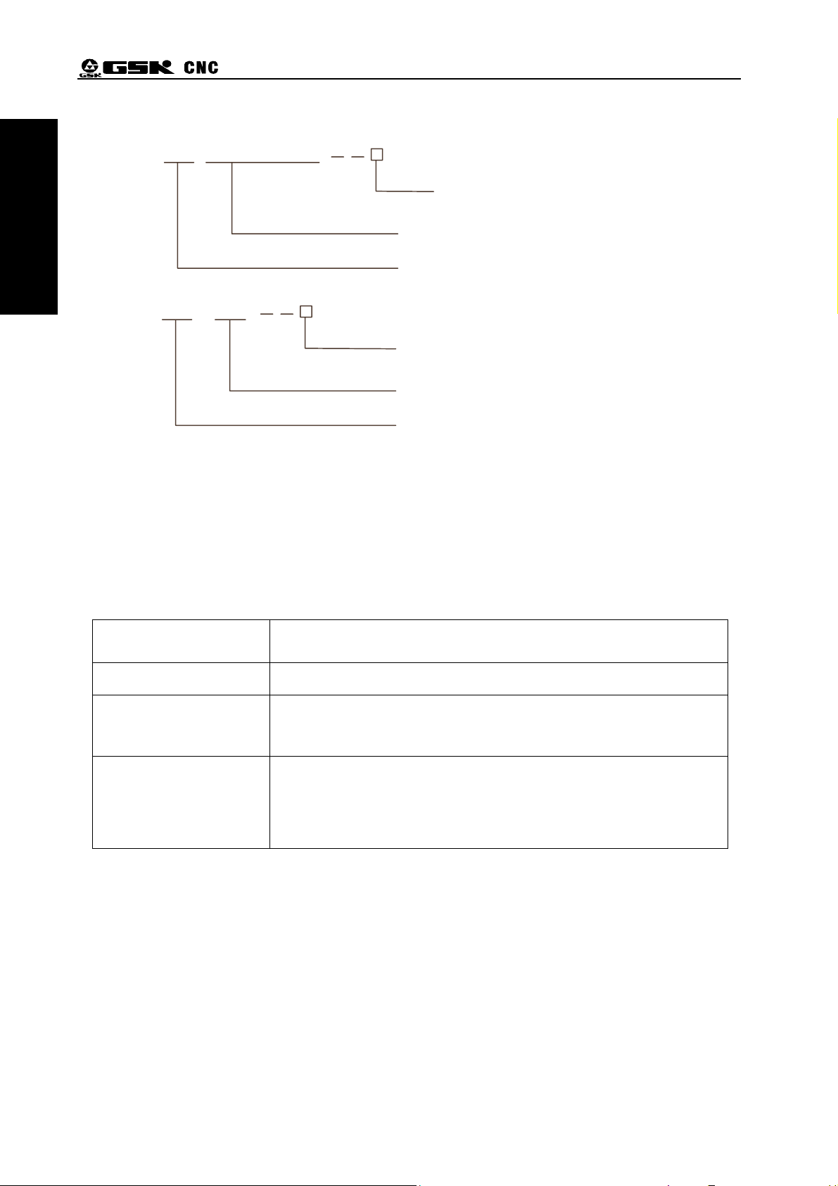
1.3 Model and Meaning
Part One Summary
GSK 980TA1(2)/TB1(2)
Assembly method:none:standard panel
(420mm×260mm)
B:box assembly
GSK980TA1(2)/TB1(2) series turning CNC system
Product logo for GSK CNC Equipment Co., Ltd.
GSK 98T
Assembly method:none:standard panel
(320mm×200mm)
B:box assembly
GSK98T series turning CNC system
Product logo for GSK CNC Equipment Co., Ltd.
Fig. 1-3
1.4 Order
Standard configuration of GSK98T is two-axis link.
GSK980TA1/TA2.GSK980TB1/TB2 can select Y as the additional axis and the user must remark
it. Refer to the supplementary about Y axis explanation.
Table 1-4
Model Explanation
GSK98T 320mm×200mm aluminium operation panel
GSK980TA1/TA2
GSK980TB1/TB2
GSK980TA1/TA2
GSK980TB1/TB2-B
420mm×260mm aluminium operation panel
GSK980TA1/TA2.GSK980TB1/TB2
Be matched with AP01 to operation box
(445mm×345mm×182mm)
4
Page 17

Chapter One Programming Fundamentals
Part Two Programming
PART TWO PROGRAMMING
5
Page 18

Part Two Pro
g
g
rammin
GSK980TA1/TA2, GSK980TB1/TB2, GSK98T CNC System User Manual
6
Page 19
Chapter One Programming Fundamentals
Chapter One Programming Fundamentals
1.1 Coordinate axis definition
It is important to stipulate the coordinate axis name and movement direction of CNC machine.
Designers, operators and maintenance personnel of CNC machine should correctly understand it,
otherwise, it causes the mistaken programming and data communication, operation accidence,
abnormal maintenance, and so on.
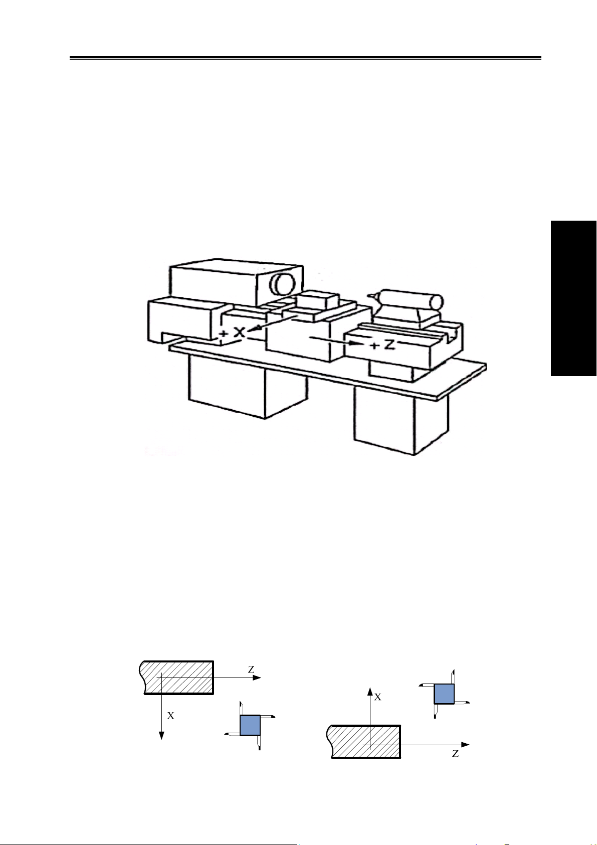
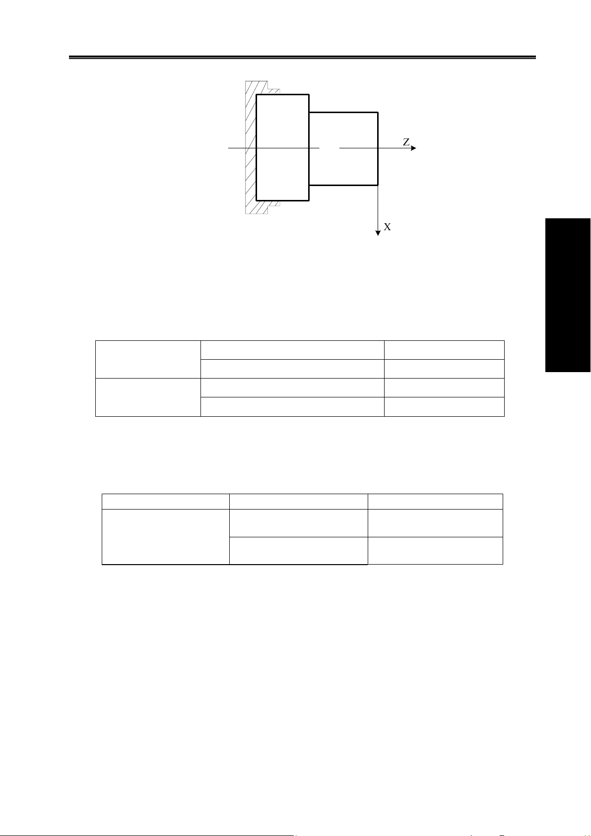
Fig.1-1-1 is a axis sketch map of CNC turning machine.
Part Two Programming
Fig.1-1-1
The system uses a rectangular coordinate system composed of X, Z axis to execute the positioning
and the interpolation movement. X axis is in the direction of front and back in the plane, and Z axis is
of left and right. The negative direction of them approach to the workpiece and positive one is away
from it, which are shown in Fig.1-1-1.
The system supports a front tool post, a rear tool post function, and describes that the tool post
before the workpiece is called as a front tool post and it behind the workpiece is called as a rear tool
post. Fig. 1-1-2 is a coordinate system of the front tool post and Fig. 1—1-3 is a rear toolpost one. It
shows exactly the opposite of X axes, but the same of Z axes from figures. In the manual, it will
introduce programming application with the front tool post coordinate system in the following figures
and examples.
Fig.1-1-2 Front tool post coordinate system Fig.1-1-3 Rear tool post coordinate system
7
Page 20
GSK980TA1/TA2, GSK980TB1/TB2, GSK98T CNC System User Manual
g
g
1.2 Machine coordinate system, Machine Zero
Machine tool coordinate system is a fixed one, its origin is taken as the machine zero installed on
the max. travel in positive X, Z axis. The machine zero is defined after the machine is designed,
manufactured and adjusted, and it is a fixed point. The machine zero is not defined when the CNC is
turned on, and generally, the automatic or manual machine zero return is executed to create the
machine coordinate system. CNC has created the machine coordinate system after the machine zero
return is completed.
Part Two Pro
rammin
Note: Do not execute the machine zero function(such as G28) without the machine zero switch installed on
the machine tool.
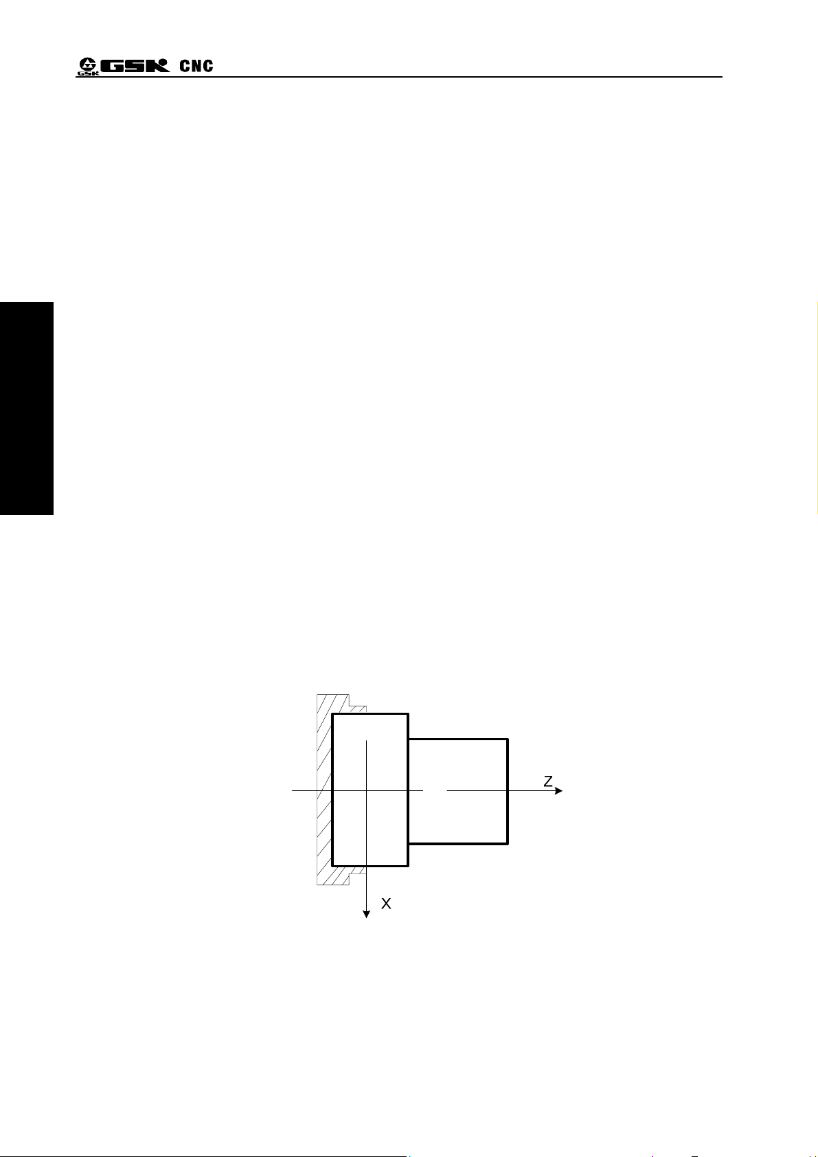
1.3 Workpiece Coordinate System and Reference Point(Program Zero)
A workpiece coordinate system (also called floating coordinate system) is used when programmers
in programming, programmer selects a known point on the workpiece as reference point (also called
program zero) to establish a new coordinate system, which is called a workpiece coordinate system.
Once the workpiece coordinate system has been established, it is valid until it is replaced by a new
one. When the system is turned off or power down, the program zero position is not saved. Using
G50 for the system creates a workpiece coordinate system. When there is no G50 in programs, the
current absolute coordinate value is taken the reference point to create a workpiece coordinate
system. The reference point selection of the workpiece coordinate system should meet the simple
programming, few dimension conversions and machining error. Generally, the reference point should
be on the reference marked by the dimension or positioning reference. For turning machine
programming, the reference point should be on the intersection point between the workpiece’s axis
and the end face of the chuck (Fig.1-3-1) or the workpiece’s end face (Fig.1-3-2).
Fig.1-3-1 reference point on end face of chuck
8
Page 21
1.4 Controlled axes
GSK98T
GSK980TA1/TA2,
GSK980TB1/TB2
Chapter One Programming Fundamentals
Fig. 1-3-2 reference point on workpiece’s end face
Table 1-4-1
Controlled axes
Simultaneously controlled axes
Controlled axes
Simultaneously controlled axes
2 axes(X,Z)
2 axes(X,Z)
3 axes X,Z,Y)
3 axes(X,Z,Y)
Part Two Programming
1.5 Input Increment
Table 1-5-1
Input/output Least input increment Least command increment
X:0.001 mm(Diameter
Metric input /metric output
Diameter/radius designation is set by NO:1#2 and the parameter is valid only to X.
The input increment is referred to the machine manufacture’s User Manual.
Z:0.001 mm
X:0.001 mm (Radius
Z:0.001 mm
)
)
X:0.0005 mm
Z:0.001 mm
X:0.001 mm
Z:0.001 mm
1.6 Maximum Stroke
Maximum stroke = least input increment×9999999
1.7 Absolute Programming and Incremental Programming
The movement of the command axis is divided into: absolute command and incremental
command. The absolute command is to use the end point of axis movement to execute programming,
which is called absolute programming. The incremental command is to use the axis movement to
directly execute programming, which is called incremental programming. For the system, the
absolute programming uses X,Z and the incremental programming uses U, W.
9
Page 22

GSK980TA1/TA2, GSK980TB1/TB2, GSK98T CNC System User Manual
g
g
Table 1-7-1
Absolute command Incremental command Remark
X U X movement command
Z W Z movement command
Example: Using an absolute coordinates, incremental coordinates and compound coordinates
compile A→B program described in Fig.1-7-1.
Part Two Pro
rammin
Fig. 1-7-1
Table 1-7-2
Programming mode
Absolute
programming
Incremental
programming
Compound
programming
Programming G1 X200 Z-50 G1 U100 W-50 G1 X200 W-50
Remark
Suppose that current coordinate point of the tool is on A, the
linear interpolation is executed.
Note: When there are command address X/ U or Z/ W at the same time, #132 alarm occurs: X, U or Z,W
exist simultaneously.
Example: G50 X10 Z20;
G01 X20 W30 U20 Z30;
1.8 Diameter and Radius Programming
The appearance of the machined workpiece is a rotating body, among which X dimension can be
specified by: the diameter and the radius, which is set by the bit of NO:1#2.
When NO:1#2 is set to 1, the radius is specified to execute programming.
When NO:1#2 is set to 0, the diameter is specified to execute programming.
10
Page 23

Chapter One Programming Fundamentals
Table 1-8-1 diameter, radius designation
Item Diameter designation Radius designation
Z command
X command
Not related to diameter, radius designation
Diameter designation Radius designation
Incremental command of
Diameter designation Radius designation
address U
Coordinate system setting
Diameter designation Radius designation
(G50)
X value of too offset
NO:2#5 specifies the diameter designation or radius
designation
Radius command of circular
Radius designation Radius designation
interpolation(R,I,K)
X feedrate
X position display
Radius change (mm/min, mm/r)
Display diameter value Display radius value
Note 1: The diameter designation is used except for special explanation in the User Manual.
Note 2: The tool offset using diameter/radius is defined that the outside diameter of workpiece
uses diameter or radius when the tool offset is changed.
Example: when the diameter is specified, and the compensation value changes 10mm,
the diameter value of the workpiece’s outside diameter changes 10mm; when the radius
is specified, and the compensation value changes 10mm, the diameter value of the
workpiece’s outside diameter changes 20mm.
Part Two Programming
1.9 Modal, Simple and Initial State
The modal is defined that after the function and state of the corresponding word are executed,
they are valid till they are done again, namely, and the same functions and states are used in the
following blocks are, the word need not be input again.
Example:
G0 X100 Z100;(rapid position to X100 Z100)
X120 Z30;(rapid position to X120 Z30,G0 is modal and can be omitted)
G1 X50 Z50 F300;(linear interpolation to X50 Z50,feedrate 300mm/min G0→G1,)
X100;(linear interpolation to X100 Z50,feedrate 300 mm/min, G1Z, 50, F300 are modal and
can be omitted)
G0 X0 Z0;(rapid position to X0 Z0)
The simple is defined that after the function and state of the corresponding word are executed,
they are valid one time, namely, and the same functions and states are used in the following blocks
are, the word needs be input again.
The initial state is defined to the default function and state after the system is turned, namely, the
system executes the initial function and state when the system is turned but does not define the
corresponding function and state. The initial state of the system includes G00, G40, G97, G98, M05,
M09, M33.
Example:
11
Page 24

Part Two Pro
g
g
rammin
GSK980TA1/TA2, GSK980TB1/TB2, GSK98T CNC System User Manual
O0001;
G0 X100 Z100; (rapid position to X100 Z100,G0 is the system’s initial state)
G1 X0 Z0 F100; (linear interpolation X0 Z0,feed per minute,feedrate 100 mm/min,
G98 is the initial state after power on)
12
Page 25

Chapter Two Structure of an Part Program
Chapter Two Structure of an Part Program
A program is defined to a series collection of commands to control the CNC machine to complete
workpiece machining. After the complied programs are input to the CNC system, the CNC system
controls the tool movement along the linear and arc, the spindle starting/stopping, the cooling and the
lubricating ON/OFF according to the commands. The commands in the program are compiled
according to the actual movement sequence of the machine.
2.1 General Structure of a Program
A program consists of a sequence of block which is composed by words. Each block is
separated by the block end command (ISO is LF, EIA is CR). “;” is used in the User Manual to mean
the end of block.
General structure of a program is shown in Fig. 2-1-1.
Program name Serial number
O0001
N0010 G50 X1000 Z100 ;
N0020 G0 X40 Z5 ;
N0030 G01 X10 Z-30 F200 ;
N0040 G01 U50 W20 F100 ;
… … ;
… … ;
… … ;
N0200 M30 ;
;
Word
End of program
Character of block end
Block
program end
Character of
Part Two Programming
Program
Fig. 2-1-1
2.1.1 Program Name
There are most 500 programs stored in GSK980TDa. To identify it, each program has only one
program name (there is no the same program name) beginning with command address O and the
following 4 digits.
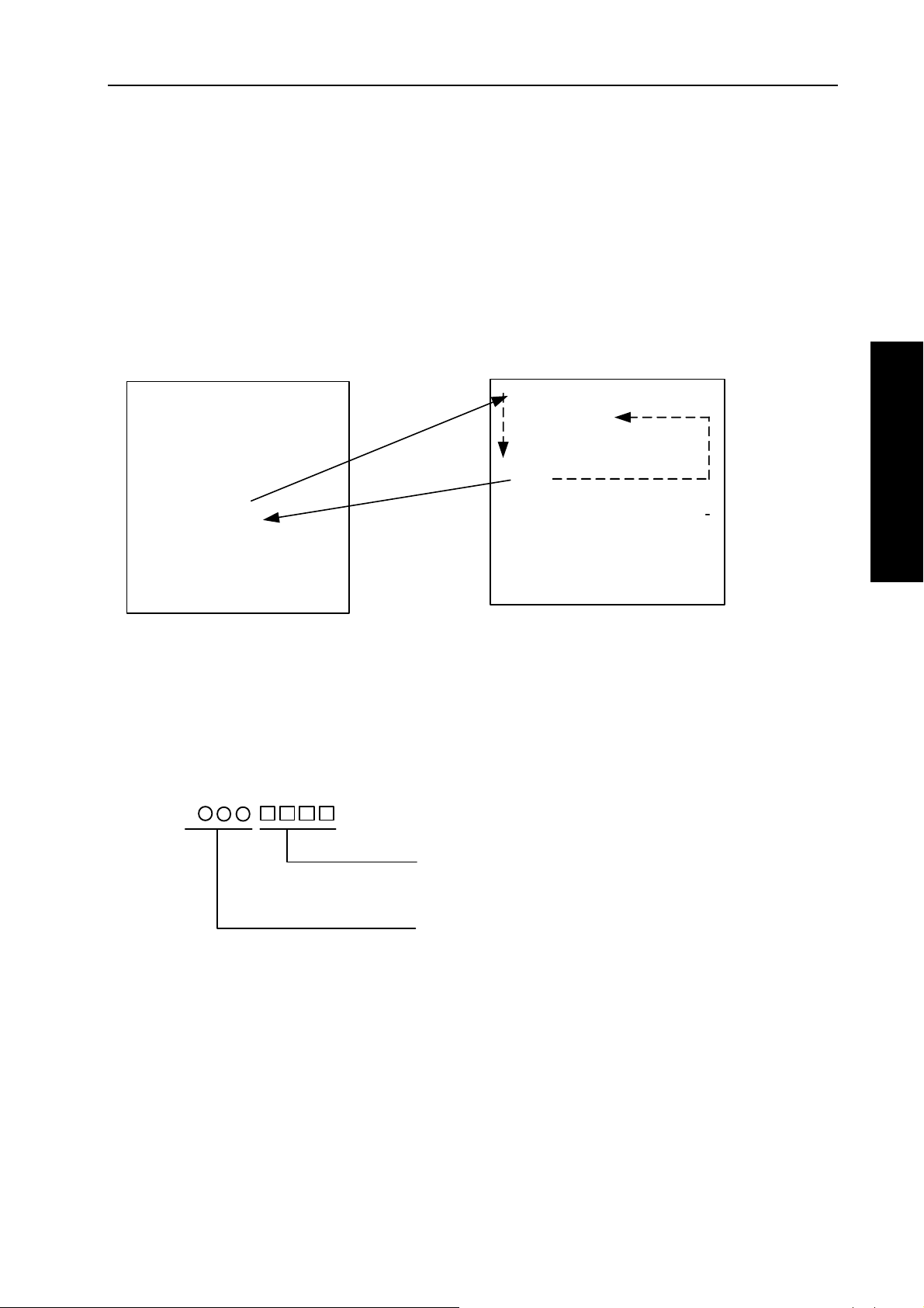
○ □□□□
Program number (0000~9999, the leading zero can be omitted)
Address O
13
%
Page 26

Part Two Pro
g
g
rammin
GSK980TA1/TA2, GSK980TB1/TB2, GSK98T CNC System User Manual
End of a program
A program starts with its program name and ends with “%”.
2.1.2 Sequence Number and Block
A program consists of many commands and one command unit is called a block (Fig.2-1-1). A
block end command is used to separate blocks (Fig. 2-1-1), and “;” is the block end command in the
User Manual.
The beginning of a block can use a sequence number composed by the address N and its
following 4 digits.
N □□□□
sequence number (0001~9999, the leading zero can be omitted)
Address N
The sequence of a sequence number is arbitrary (NO:2 # 7 sets whether another sequence
number is inserted) and its interval is not equal (the interval size is set by P50, the interval of GSK98T
system is set by P119). All blocks can be with sequence numbers and some key blocks can be with
them. Generally, sequence number is from the small to the big according to machining sequence.
2.1.3 Word
A word is an element of a block. A word is composed by an address and its following
digit(some is with + or - before the digit), which is shown in Fig. 2-1-3:
X
1000
Address Digit
Word
Fig. 2-1-3-1
An address is one of English letters. The address describes the meaning of its following
numerical. In the system, the useful addresses and meanings are shown in Fig. 2-1-3-1. Some
address has different meanings according to different commands.
Address Value range Function
Table 2-1-3-1 address list
Z
Address Digit
-500
Word
O
N
G
X
14
Z
-9999.999~9999.999(mm)
-9999.999~9999.999(mm)
0~9999
1~9999
00~99
0~9999.999(s)
Program name
Block number
Preparatory function
X coordinate
Pause time
Z coordinate
Page 27

Chapter Two Structure of an Part Program
Address Value range Function
U
W
R
-9999.999~9999.999(mm)
-9999.999~9999.999(mm)
0.001~9999.999 (mm)
-9999.999~9999.999(mm)
-9999.999~9999.999(mm)
0.001~9999.999(mm)
-9999.999~9999.999(mm)
-9999.999~9999.999
(mm)
0~9999.999(mm)
0.001~9999.999(mm)
1~9999999(times)
0~9999.999(mm)
0~9999.999(mm)
0~9999.999(mm)
-9999.999~9999.999(mm)
X increment
X finishing allowance in G71,G72, G73
Cutting depth in G71
Travel of X tool retraction in G73
Z increment
Cutting depth in G72
Z finishing allowance in G71,G72, G73
Z tool retraction in G73
Arc radius
Tool retraction in G71, G72
Roughing cycle times in G 73
Tool retraction in G74, G75
Tool retraction distance G74, G75
Finishing allowance in G76
Taper in G90, G92, G94, G96
Part Two Programming
K
F
S
T
M
P
-9999.999~9999.999(mm)
I
0.06~25400(tooth/inch)
-9999.999~9999.999(mm)
X vector between arc center and starting
point
Metric thread tooth
Z vector between arc center and starting
point
1~8000(mm/min)
0.001~500(mm/r)
0.001~500(mm)
0~9999(r/min)
0~9999(m/min)
00~04
10~99
0100~0800
00~99
Specifying spindle constant surface speed
Miscellaneous function output, program
Feedrate per minute
Feedrate per rev
Metric thread lead
Specifying spindle speed
Multi-gear spindle output
Subprogram call
Tool function, subprogram call
executed flow, subprogram call
1~9999999(0.001s)
0~9999
0~999
0.001~9999.999(mm)
See Chapter 3.4, G76
Call subprogram number
Call times of subprogram
X circular moving distance in G74, G75
Thread cutting parameter in G76
Pause time
Explanation
1~9999
Initial block number of finishing in the
compound cycle command
15
Page 28

Part Two Pro
g
g
rammin
GSK980TA1/TA2, GSK980TB1/TB2, GSK98T CNC System User Manual
Address Value range Function
1~9999
Q
H
L
The limited values described in Table 2-1-3-1 are for the CNC device, but the limited values for
the machine are not described here. Please refer to the user manual, another user manual from the
machine manufacturer when programming.
0.001~9999.999(mm)
1~9999.999(mm)
01~99
01~99
End block number of finishing in the
compound cycle
Z circular moving distance in G74, G75
First cutting depth in G76
Operand in G65
Thread heads in G92
2.2 Relationship between Command Numerical Value and Decimal Point
In the system, some command cannot be with a decimal point, and No:11#0 sets whether the
decimal point is used when programming, and the relationship between the command numerical
value and the decimal point is shown in Fig.2-2-1:
Address
X
Z
U
W
R
I
K
P
S
Table 2-2-1
Having a
decimal point
Yes
Yes Command:G1 Z20
Yes Command:G1 U20
Yes Command:G1 W20
Yes
Yes
Yes
No
No
NO:11#0=1 NO:11#0=0 Remark
Command:G1 X20
Positioning point:20
Command:G4 X20
Delay:20s
Positioning point:20
Incremental value:
20mm
Incremental value:
20mm
Command:G4 P2
Delay:0.002s
Command:G1 X20
Positioning point:0.02
Command:G4 X20
Delay:0.02s
Command:G1 Z20
Positioning point:0.02
Command:G1 U20
Incremental value:
0.02mm
Command:G1 W20
Incremental value:
0.02mm
It is the
same as the
address X
It is not
related to
the decimal
point
16
Page 29
Chapter Two Structure of an Part Program
2.3 Subprogram
2.3.1 Main Program and Subprogram
To simply the programming, when the same or similar machining path and control procedure is
used many times, its program commands are edited to a sole program to call. The main program is
defined to call others and the subprogram(end with M99) is to be called. They both take up the
program capacity and storage space of system. The subprogram has own name, and can be called at
will by the main program and also can run separately. The system returns to the main program to
continue when the subprogram ends, which is shown below:
Part Two Programming
Ο0001;
G50 X100 Z100;
M3 S1 T0101;
G0 X0 Z0;
G1 U200 Z200 F200;
M98 P21006;
Call
Return
Ο1006;
G1 X50 Z50;
U100 W200;
G03 U30 W-15 R15 F250;
M99;
%
G0 X100 Z100;
M5 S0 T0100;
M30;
%
Main program
Fig. 2-3-1-1
2.3.2 Subprogram Call(M98)
Command format:
M98
P
Called subprogram number(0000~9999). The leading zero
of subprogram number can be omitted when the calling times is
not input; the subprogram number must be with 4 digits when
the calling times is input;
Subprogram
Call times: 1-9999. The calling times cannot be input when it is 1.
Command function: After other commands of current block are executed in M98, CNC calls
subprograms specified by P instead of the next block, and subprograms are
executed 9999 times at most.
Note: The system cannot call a subprogram in MDI mode.
2.3.3 Return from subprogram(M99)
Command format
17
Page 30
GSK980TA1/TA2, GSK980TB1/TB2, GSK98T CNC System User Manual
g
g
Part Two Pro
rammin
M99
Command function: After other commands of the current block (in the subprogram) are executed,
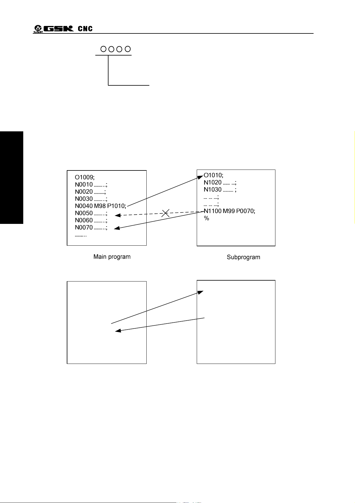
Example: Execution path of calling subprogram (with P in M99) is shown in Fig. 2-3-3-1.
Execution path of calling subprogram (without P in M99) is shown in Fig. 2-3-3-2.
P
Return to the block number (0001~9999)of the main program, the
leading zero can be omitted.
the system returns to the main program and continues to execute next block
specified by P, and calls a block following M98 of current subprogram when P
is not input. The current program is executed repeatedly when M99 is defined
to end of the main program.
Fig. 2-3-3-1
Ο0001;
G50 X100 Z100;
M3 S1 T0101;
G0 X0 Z0;
G1 U200 Z200 F200;
M98 P21006;
G0 X100 Z100;
M5 S0 T0100;
M30;
%
Main program Subprogram
The system can call fourfold-embedded subprograms, namely can call other subprograms in
another subprogram (Fig.2-3-3-3 is an example of double-embedded).
Call
Return
Fig. 2-3-3-2
Ο1006;
G1 X50 Z50;
U100 W200;
G03 U30 W-15 R15 F250;
M99;
%
18
Page 31

Chapter Two Structure of an Part Program
Fig. 2-3-3-3 double-embedded subprogram
Part Two Programming
19
Page 32

Part Two Pro
g
g
GSK980TA1/TA2, GSK980TB1/TB2, GSK98T CNC System User Manual
Chapter Three Preparatory Function G Command
3.1 Category of Preparatory Function G Command
Preparatory function---A G command consists of command address G and its following 2 digits
numerical value, and is used for defining the motion path of the tool relative to the workpiece, setting
the coordinates and so on. G commands are shown in Fig. 3-1-1.
G
Command value(00~99,the leading zero can be omitted)
rammin
Address G
G words are divided into 6 groups (00, 01, 02, 03, 06, 07). That commands in the group 01 are
simple and others are modal.
After G commands are executed, their defined functions and states are valid until they are
changed by others in the same group, the previous functions and states are cancelled.
The initial G command is the initial mode after the system is turned on, the commands in the
initial mode include G00, G97, G98, G40, G21.
The defined functions and state are valid one time after the simple G command is executed, and
it must be input again when it is executed every time
After the system is switched on, the valid modal G commands which are not executed their
functions or states are called initial mode G command. Take it as the initial mode G command to be
executed when it is not be input after the system is switched on. The initial commands of GSK980TDa
include G00, G40, G97, G98.
Several G codes (Group 00 and 01 must not be in the same block) which belong to different
groups can be commanded in the same block. No.129 alarm occurs when more than two G codes
which belong to the same group are commanded in the same block. When G codes with common
word which belong to different group are in the same block, their functions are valid simultaneously
and are unconcerned with their sequence. The system alarms when other G codes except for ones
described in Table 3-1-1 or G codes which have no selection functions.
Table 3-1-1 G command list
ommand Group Format Explanation
Positioning, rapid
*G00
01
G01 G01 X(U)__Z(W) __ __F Linear interpolation
G02 G02 X(U)_Z(W)_R_(I_K_) F_ Circular interpolation CW
20
G00 X(U)__Z(W) __
traverse, speed rate of
each aixs set by
parameters
Page 33

Chapter Three Preparatory Function G Code
G03
G04 00
G10 00
G20
*G21 G21 Metric selection
06
G03 X(U)_Z(W)_R_(I_K_) F_ Circular interpolation
CCW,
G04 P_;or G04 X_;
G10 P__(parameter number)Q__
(numerical value)
A program specifying a
parameter function
Dwell
G20 Inch selection
G28 X(U)__Z(W) __ Return to reference point,
G28 00
and X, Z specifies the
middle point
G31 00
G32
G33
G34
01
01
01
*G40
G41
07
G42
G31 X(U)__ Z(W)__ F__
Skip function
G32 X(U)__Z(W) __F(I) Invariable pitch thread
cutting
G33 Z(W) __F(I);G33 X(U) __F(I)
Tapping cycle
G34 X(U)__Z(W) __F(I) K__ Variable pitch thread
cutting
G40 Tool radius compensation
cancel
G41 Tool radius compensation
(left)
G42 Tool radius compensation
(right)
Part Two Programming
G50 00 G50 X(U)__Z(W)__ Coordinate system setting
G51
00
G65 00
G70
G71
G51 X(U)__ Z(W)__
G65 Hm P#I Q#J R#K
G70 P(ns) Q(nf) Finishing cycle
G71 U(ΔD) R(E)
Local coordinate system
function
Macro code(see the
following)
Outer roughing cycle
G71 P(NS) Q(NF) U(ΔU)W(ΔW) F(F)
S(S) T(T)
G72
G72 W (ΔD) R (E)
End roughing cycle
G72 P(NS) Q(NF) U(ΔU) W(ΔW) F(F)
S(S) T(T)
G73
00
G73 U (ΔI) W (ΔK) R (D)
G73 P(NS) Q(NF) U(ΔU) W(ΔW) F(F)
Closed cutting cycle
S(S) T(T)
G74
G75
G74 R(e)
G74 X(U) Z(W) P(Δi) Q(Δk) R(Δd) F(f)
G75 R(e)
End deep hole machining
cycle
Outer/inner grooving cycle
G75 X(U) Z(W) P(Δi) Q(Δk) R(Δd) F(f)
G76
G90
G92 G92 X(U)__ Z(W)__ R__ F(I) __J __K__ Thread turning cycle
01
G76 P(m) (r) (a) Q( dmin) R(d)
G76 X(U) Z(W) R(i) P(k) Q( d) F(L)
△
△
G90 X(U)__ Z(W)__ R__ F__ Outer, inner turning cycle
Compound thread cutting
cycle
G94 G94 X(U)__ Z(W)__ R__ F__ End turning cycle
G96 02 G96 S Constant surface control
21
Page 34

Part Two Pro
g
g
GSK980TA1/TA2, GSK980TB1/TB2, GSK98T CNC System User Manual
*G97 G97 S Constant surface control
cancel
*G98
G99 G99 Feed per rev
Note 1: When the system is turned on, it is in the state of G command with *.
Note 2: G commands in Group 00 are simple.
Note 3: 98T system has G41/G42/G40, G65.
03
G98 Feed per minute
3.2 Simple G Command
3.2.1 Rapid Positioning(G00)
rammin
Command format
Function:
X, Z rapidly traverses at the respective traverse speed to the position specified by X(U),
:G00 X(U)_ Z(W)_ ;
Z(W).
Explanation:X(U):absolute (incremental) coordinate of X positioning end point;
Z(W):absolute (incremental) coordinate of Z positioning end point;
1. X, Z rapidly traverses at the respective traverse speed and their combined path is really
not linear, so maybe they cannot reach the end points simultaneously, please pay
attention to it when programming ( Fig. 3-2-1-1).
2. X, Z rapidly traverses at the speed separately set by P21, P22, for 98T system, they are
separately set by P17, P18 or are adjusted by pressing
operation panel, or are performed by selecting manual rapid override which has five
grades including Fo, 25%, 50%, 75%, 100%. (Fo speed is set by P32, but for 98T
system, it is set by P69)
3. The tool does not traverse when there is a positioning parameter after G00, the system
only changes the current tool traverse mode into G00.
on the
Fig. 3-2-1-1
Example:the tool rapidly traverses from A to B, which is shown in Fig. 3-2-1-2:
22
Page 35

Programming:
Chapter Three Preparatory Function G Code
Part Two Programming
Fig. 3-2-1-2
G0 X20 Z0;(absolute programming, diameter programming)
G0 U-22 W-18;(incremental programming, diameter programming)
G0 U-22 Z0;(compound programming, diameter programming)
3.2.2 Linear Interpolation(G01)
Command format
:G01 X(U)_ Z(W)_ F_;
Function:the tool traverses to the specified position at the feedrate (mm/min)specified by F. The
interpolation path is shown in Fig. 3-2-2-1.
Explanation:X(U):absolute (incremental) coordinate of X interpolation’s end point;
Z(W):absolute (incremental) coordinate of Z interpolation’s end point;
F:is combined federate of X, Z, is modal. It value is related to G98 OR G99, which is
shown in 3-2-2-1:
Table 3-2-2-1
G98(mm/min) G99(mm/r)
Value range 1~8000 0.001~500
Command path:
23
Page 36

GSK980TA1/TA2, GSK980TB1/TB2, GSK98T CNC System User Manual
g
g
L
L
Part Two Pro
rammin
Z
X
L
End point
0
Current point
U/2
Z(W)
X
1. Feedrate specified by F is valid until a new F value is specified. Feedrate specified by F is
counted by linear interpolation. When F is not commanded in programs, feedrate uses F
feedate of initial speed.(refer to P103 about setting, P70 replaces P103 for 98T system).
For interpolation mode of two axes simultaneously moving, F is specified to the composite
feedrate of two axes.
Fx ×=
3-2-2-1:
U
F
:
It shows from Fig.
X feedrate
Fig. 3-2-2-1
Z feedrate
P27(P71 replaces P27 for 98T system)can set the upper of cutting feedrate F. When the
2.
actual cutting feedrate (federate after using override) exceeds the upper, NO.11 alarm
occurs, feedrate unit is mm/min.
3. When the positioning command following G01 is not commanded, the tool does not traverse,
the system only changes the current tool traversing mode to G01.
4. Pressing
0%~150%.
Example: compile the linear interpolation program from current point to end point, which
Program (diameter programming):
G01 X60.0 Z-25;(absolute programming)
G01 U20.0 W-25.0;(incremental programming)
shown in Fig.
Fz ×=
W
3-2-2-2.
F
(L=
22
/4UW+
can tune the feedrate override, which is divided into 16 grades from
,U is a diameter value)
24
Page 37

Chapter Three Preparatory Function G Code
Part Two Programming
Fig. 3-2-2-2
3.2.3 Circular Interpolation(G02/G03)
Command format
:
Function: X, Z from starting point (the position before the current block runs) moves along the radius
specified by R or CW/CCW interpolates along the circle center defined by I, K value to end
point specified by X(U), Z(W).
G02 motion path is an arc from starting point to end point along CW (the rear post tool
coordinate system)/CCW (the front tool post coordinate system), which is shown in
Fig.3-2-3-1.
G03 motion path is an arc from starting point to end point along CCW (the rear post tool
coordinate system)/CW (the front tool post coordinate system), which is shown in
Fig.3-2-3-2.
Explanation:X(U):absolute (incremental) coordinate of X circular interpolation’s end point;
Z(W):absolute (incremental) coordinate of Z circular interpolation’s end point;
R:arc radius;
I:X difference value of circle center relative to starting point of arc; (radius command)
K:Z difference value of circle center relative to starting point of arc;
X, U, Z, W, I, K range: -9999.999 mm~9999.999 mm, R range: 0mm~9999.999mm
F:cutting speed of arc.
25
Page 38

Part Two Pro
g
g
GSK980TA1/TA2, GSK980TB1/TB2, GSK98T CNC System User Manual
Command path:
rammin
Fig.3-2-3-1 G02 path Fig.3-2-3-2 G03 path
CW or CCW interpolation is related that the system uses the front tool post coordinate system or
the rear tool post coordinate system. The system uses the front tool post coordinate system,
which is shown in Fig. 3-2-3-3.
Example: G02 compiles a program shown in Fig. 3-2-3-4:
Fig. 3-2-3-3
Fig. 3-2-3-4
Program(the current point of the tool is the starting point):
G02 X63.06 Z-20 R19.26 F300 ; or
G02 U17.81 W-20.0 R19.26 F300 ; or
26
Page 39

Chapter Three Preparatory Function G Code
G02 X63.06 Z-20 I18.929 K-3.554 F300 ; or
G02 U17.81 W-20.0 I18.929 K-3.554 F300 ;
Note 1: the arc center is specified by I, K which separately corresponds to X, Z (Fig. 3-2-3-1, Fig.3-2-3-2). I,
K mean the vector component from starting point to circle center, with signs.
Note 2: when I, K or, R is not specified in the command format, the system executes the interpolation
along G01 path.
Note 3: one or all of X(U), Z (W) can be omitted. Omitting one means the starting point and end point of
the axis are consistent; omitting all means the starting point and end point are in the same
position.
Note 4: when X (U), Z (W) are omitted simultaneously, and I, K are circle center, which means the arc path
is a full circle; I, K and R cannot be commaned simultaneously, otherwise, the system alarms.
Note 5: when I=0 or K=0, they can be omitted.
Note 6: when R is specified, R>0, the specified arc is less than 180 degree; when the arc is more than 180
degree, I, K are specified; R, I, K are simple.
Note 7: when R error range exceeds the value set by No. 98, No.26 alarm occurs.
Part Two Programming
Note 8: in MDI mode, I, K are valid but I, K values are not displayed.
3.2.4 Chamfering/Cornering Arc
Command format:C_:chamfer
B_:chamfer arc transition
Function:the above is added to the end of the block in G01 or G02, G03, the chamfering at the
cornering or the arc transition is executed automatically.
Explanation
:the chamfering following C specifies the distance from the virtual inflection point to
corner starting point and end point, the virtual inflection point is presumed not to
execute the corner, the corner point actually exists, which is shown below:
(1) G01 U100 W-50 C10;
(2) W-100;
Insert chamfer blocks
C
C
Virtual
inflection point
Fig. 3-2-4-1
After the chamfer arc transition is B, the chamfer arc radius is specified, which is shown
below:
27
Page 40

Part Two Pro
g
g
GSK980TA1/TA2, GSK980TB1/TB2, GSK98T CNC System User Manual
Fig. 3-2-4-2
Limits:
Cornering and chamfering arc are executed only in the specified plane, and cannot be
1.
rammin
executed by the parallel axes.
2. After a block for cornering and chamfering arc transition, G01 or G02, G03 must be
followed, and the cornering and chamfering arc transition are disabled when there is no
these commands in the following block.
3. The system alarms when the inserted block for the chamfering or arc transition causes the
tool exceeding the previous interpolation movement range.
4. The Chamfering or cornering arc transition cannot be specified in the block where the
coordinate system is changed or which is followed by the reference point return is
executed.
5. The chamfer arc transition cannot be specified in the block used for the thread machining.
6. The chamfering and cornering values cannot be negative.
3.2.5 Dwell G04
Command format
G04 X__ ;
G04 U__ ;
G04 P__ ;or
:
Function
Explanation
28
When G04 executes the dwell operation, the system delays the specified time to execute
:
the next block. The specified time range: 0.001s~9999.999s.
When P, X or U is specified, it means the exact stop between block, dwell time is
influenced by No. 031 (98T system is set by P21), the bigger the parameter set value, the
longer the dwell time is;
when No:11#0 is set to 1, the unit is shown in Fig. 3-2-5-1:
:
Table 3-2-5-1
Address P X U
Unit 0.001s 1s 1s
When No:11#0 is set to 0, the unit is shown in Fig. 3-2-5-2:
Page 41

Chapter Three Preparatory Function G Code
Address P X U
Unit 0.001s 0.001s 0.001s
Note 1: when G04 is execute, P and X or P and U are in the same block, X, U are valid, P is invalid.
Note 2: G04 and M98 cannot be in the same block, otherwise, the alarm (eer76) occurs.
Note 3: G04 and other commands in the Group 01 cannot be in the same block, otherwise, the
alarm (err131) occurs.
3.2.6 Programs Specifying Parameter Function (G10)
Command format
:G10 P(parameter number) Q(numerical value)
Function:When G10 is specified, the actual output of related parameters from the one specified by
G10 is executed
Example:G10 P45 Q1000
After the block is executed, No. 45 value is automatically changed into 1000
Explanation:(1)Parameter range specified by P:all data parameter of the system;
(2)Q range and unit are related the specified parameter;
(3)Parameter(Q)set value has no decimal point. It automatically cleared away by the
system when the decimal point is input when programming.
3.2.7 Machine Zero Return(G28)
Command format
Function
The commanded axis goes through the middle point specified by X (U), Z(W) to return to
:
G28 X(U)_ Z(W)_ ;
:
the machine zero. One or two axes can be specified in G28.
Table 3-2-7-1
Part Two Programming
Explanation
(1) Rapid traverse to middle point from current position(A point→B point) ;
(2) Rapid traverse to reference point from the middle point(B point→R point) ;
(3) When the machine is not locked and after the machine reference point return is
Command Function
G28 X(U) X returns to machine zero, Z remains unchanged
G28 Z(W) Z returns to machine zero, X remains unchanged
G28 X, Z remain unchanged
G28 X(U) Z(W) X, Z return to machine zero simultaneously
G28 operation process (Fig3-2-7-1):
:
completed, the machine zero return indicator is ON and the machine coordinates are
cleared.
29
Page 42

Part Two Pro
g
g
rammin
GSK980TA1/TA2, GSK980TB1/TB2, GSK98T CNC System User Manual
Fig. 3-2-7-1
Note 1: After the system is turned on, the system has not executed the manual machine zero return firstly,
the path from the middle point to the machine zero is the same that of the manual machine zero
return when G28 is executed.
Note 2: A point→B point and B point →R point, X, Z moves at its respective speed, so, their paths are not
linear.
Note 3: The machine zero return function cannot be executed when there is no the machine zero installed
on the machine.
Note 4: When No.006: Bit6 is set to 1, the system is firstly turned on to execute G28 and after the machine
zero return is executed, the set coordinate system is valid; when G28 is executed again and after
the machine zero return is executed, the set coordinate system is invalid.
3.2.8 Workpiece Coordinate System Setting(G50)
1)Workpiece coordinate system setting
Command format:G50 X_ Z_ ;
Function:Set a workkpiece coordinate system. Two code parameters specify the absolute
coordinate value of tool nose position of current tool post on a new workpiece
coordinate system. G50 does not make the motion axis move.
Explanation: X :X absolute coordinate of current tool nose in the workpiece coordinate system;
Z :X absolute coordinate of current tool nose in the workpiece coordinate system;
1. After the coordinate system is established, the position of the absolute command is
presented in the coordinate system till one new coordinate system is established by
G50.
2. When the diameter programming is specified, the diameter is specified to X; when
the radius programming is specified, the radius is specified to.
30
Page 43

Chapter Three Preparatory Function G Code
Fig. 3-2-8-1
After G50 X100 Z100 is executed, the workpiece coordinate system is thus set (shown in Fig.
3-2-8-1) and the tool nose’s current position in the workpiece coordinate system is defined. Refer
to Section 4.4 Tool Setting for coordinates setting methods.
Note 1: G50 cannot be in the same block with the commands included to Group 01, otherwise, ERR131
alarm occurs.
Note 2: When using G50 sets the coordinate system in the tool offset cancel mode. After the coordinate is
set, the absolute coordinates are those of G50 set value; the tool offset cancel is executed in MDI
mode: “T0100 G00 U0 W0”. Suppose that the current tool offset state is T0101.
Note 3: When using 50 sets the coordinate system in tool offset state, there are two kind of displaying
absolute coordinates:
A. The tool offset has been executed(have movement command after tool offset) and after the
setting is done, the absolute coordinates are the one set by G50, which is shown below:
Table 3-2-8-1
Program(execute tool compensation
in coordinate offset mode)
Absolute coordinate
display value
No. 01 tool
compensation value
G0 X0 Z0 X:0 Z:0 X:-12
T0101 X:12 Z:23
Z:-23
G0 X0 Z0 X: 0 Z:0
G50 X20 Z20 X:20 Z:20
Part Two Programming
B. The tool offset has not executed(have no movement commands after tool offset),
including tool offset cancel and tool offset setting, after the setting is done, the absolute
coordinates are the tool offset values, which is shown below:
Table 3-2-8-2
Program(execute tool compensation
in coordinate offset mode)
Absolute coordinate
display value
No. 01 tool
compensation value
G0 X0 Z0 X:0 Z:0 X:-12
T0101 X:12 Z:23
Z:-23
G0 X50 Z50 X:50 Z:50
T0100 X:38 Z:27
G50 X20 Z20 X:8 Z:-3
31
Page 44

GSK980TA1/TA2, GSK980TB1/TB2, GSK98T CNC System User Manual
g
g
Table 3-2-8-3
Part Two Pro
rammin
Program(execute tool compensation
in coordinate offset mode)
G0 X0 Z0 X:0 Z:0 X:-12
T0101 X:12 Z:23
G50 X20 Z20 X:32 Z:43
2)Coordinate system translation
Command format
Function:The tool nose position in the previous absolute coordinate system translates the
Explanation:When the diameter programming is specified, X is done by diameter; when the
Note: There is no M, S, T in the block of G50, otherwise, the system alarms.
3.2.9 Workpiece Coordinate System Offset(G51)
Command format
:G50 U_ W_ ;
distance set by a parameter. Namely, the tool nose position in the new coordinate
system corresponding to the previous absolute coordinate system is X+U,Z+W.
radius programming is specified, X is done by radius.
:G51 X(U) Z(W)
Absolute coordinate
display value
No. 01 tool
compensation value
Z:-23
Function: G51 is specified to complete the workpiece coordinate system offset when programming.
Explanation:When the absolute coordinate programming is used, for example, G51 X_ Z_, means
that the current coordinate system offsets to the position specified by X, Z;
When the incremental coordinate programming is used, for example, G51 U_ W_,means the
current coordinate system offsets the displacement vlaues specified by U, W;
Specify G51, X0, Z0 to cancel the workpiece coordinate offset and recover the previous
workpiece coordinate system.
Example 1:use “G51 X_ Z_ ” to execute the offset
Program
G50 X100
Z100
G51 X-10 Z-10 X110 Z110 X100 Z100
G51 X20 Z20 X80 Z80 X100 Z100
G0 X10 Z10 X10 Z10 X30 Z30
G51 X0 Z0 X30 Z30 X30 Z30 Cancel the workpiece coordinate system offset
Absolute
coordinates
X100 Z100 X100 Z100 G50 sets coordinate system
Machine
coordinates
Explanations
G51 executes the offset corresponding to the
previous workpiece coordinate system instead
of the current coordinate system.
Example 2:use “G51 U_ W _ ” to execute the offset.
Program
G50 X100
Z100
32
Absolute
coordinates
X100 Z100 X100 Z100
Machine
coordinates
Explanations
G50 sets coordinate system
Page 45

Chapter Three Preparatory Function G Code
v
A
G51 U-10
W-10
G51 U20 W20 X90 Z90 X100 Z100
X110 Z110 X100 Z100 G51 executes the offset corresponding to the
previous workpiece coordinate system instead
of the current coordinate system.
G0 X10 Z10 X10 Z10 X20 Z20
G51 X0 Z0 X20 Z20 X20 Z20
Cancel the workpiece coordinate system offset
Note 1: Executing G51, G50, G28 and the manual machine zero return operation (machine zero return can
automatically set the coordinate system) can automatically cancel offset value.
3.2.10 Feed per minute (G98)
Command format:G98 Fxxxx
Function:G98 is the feed per minute. The distance the tool traverses per minute is commanded by
the numerical value following F, unit: mm/min.
Explanation:G98 is modal. Once G98 state is commanded, it is valid till G99 is executed.
3.2.11 Feed per Rev (G99)
Command format:G99 Fxxxx
Part Two Programming
Function: G99 is the feed per rev. The tool feed amount per the spindle rev is commanded by the
numerical value following F, unit: mm/r.
Explanation: G99 is modal. Once G99 state is commanded, it is valid till G98 is executed.
Table 3-2-11-1 Difference between feed per minute and feed per rev
Feed per minute Feed per re
ddress
designation
Command
designation
Range
1 mm/min~8000mm/min
F F
G98 G99
0.001 mm/r~500.00mm/r
(F1~F8000)
(F0.001~F500)
Feed per minute, feed per rev are limited in some speed. The limited values
Limited value
are set the machine manufacturer.
(The limited value is the numerical value following the override)
Override
Feed per minute, feed per rev are adjusted by the override 0~150%.
Note 1: When the position encoder’s speed is below 1 r/min, the speed becomes uneven. The speed below 1
r/min can be used when the even speed is not required. Below 1r/min, the slower the speed is, the
more uneven the speed is.
Note 2: G98, G99 are modal. They are valid after they are commanded till another command is executed.
Note 3: F code can permit inputting up to 7 digits. The system alarms when the input feedrate exceeds the
limit.
Note 4: The position encoder must be installed on the spindle when the feed per rev is executed.
3.2.12 Constant Surface Control (G96, G97)
Command format
33
:G96 S__ ;constant surface control, and the numerical value following S specifies
Page 46

GSK980TA1/TA2, GSK980TB1/TB2, GSK98T CNC System User Manual
g
g
the surface speed of tool nose in the tangential direction.
G97 S__ ;cancel the constant surface control code. The numerical value
following S specifies the spindle speed.
Function:The constant surface is defined that the surface speed following S is constant. along the
tool’s position changing, the spindle speed is counted according to the previous given
surface speed, the spindle speed is converted into the corresponding voltage to output the
spindle control unit, which gets the constant relations between the instantaneous position
Part Two Pro
rammin
of tool and the workpiece’s surface.
Explanation:The surface speed unit is shown below:
Table 3-2-12-1
Input unit Surface speed unit
Metric m/min
The surface speed units are different according to the machine manufacturers.
When the constant surface control is executed, the rotary axis must be set on Z (X=0) of
the workpiece coordinate system.
X
Z
34
(n)
3000
2800
2600
2400
2200
2000
1800
1600
1400
1200
1000
800
600
400
200
0
At about 160mm(radius),the numerical values of
the spindle speed(r/min)and the surface speed
(m/min)are consistent.
S
is
6
0
4
0
0
3
0
0
2
0
1
0
0
0
5
0
20
40
60 80
100
120140160
0
m
0
min
180
200220240260280 300
Unit(mm)
Fig. 3-2-12-1
Page 47

Chapter Three Preparatory Function G Code
1) Spindle speed override
The specified surface speed or speed can use the override 50%,60%,70%,80%,90%,
100%,110%,120% according the spindle override selection.
2) Max. spindle speed limit
Using the numerical value following G50 S can command max. spindle speed (r/min) in the
constant surface control state.
G50 S__ ;
In the constant surface control state, the spindle speed is limited to its max. speed when it
exceeds the above specified value.
3) Constant surface control in G00
For the block in G00, when the constant surface speed control is executed, the system
counts the surface speed at the end point of the block instead of the surface speed of the tool
position which is changed constantly, which reason is that the rapid traverse does not
execute the cutting.
Note 1: When the system is turned on, the state which does not set max. spindle speed is the unlimited
state. For the limit, the system is only in G96 instead of G97.
Note 2: The lower limit value of the spindle speed in the constant surface speed control is controlled by
P78 (for 98T system, it is controlled by P100). P78=100: when G50 S0 is executed, the spindle
speed is 100 r/min.
Note 3: The commanded S value in G97 still retains in G96, i.e. it remain unchanged in G97. its value
recovers when the system returns to G96 state.
G96 S50; (50m/min)
G97 S1000;(1000r/min)
G96 X3000;(50m/min)
Note 4: It does not run when the machine is locked, X coordinate value in the corresponding program
changes and the system executes the constant surface control.
Note 5: The constant surface control is valid when thread cutting is executed, so, the constant surface
control is invalid in G97, which makes the spindle rotate at the same speed.
Note 6: Feed per rev (G99) is still valid without useful meaning in G96.
Note 7: When G96 state is changed into G97 and there is no S code (r/min) in G97, the final speed in G96 is
used as S code in G97.
N100 G97 S800;(800r/min)
…
N200 G96 S100;(100m/min)
…
N300 G97; (Xr/min)
X is speed of the block which is front of N300, i.e. when G96 state is changed into G97, the spindle
speed does not change. When G97 state is changed into G96, S value in G96 is value. S=0 m/min
when S value is not commanded.
Part Two Programming
3.2.13 Skip Function (G31)
Command format:
G31 X(U)__ Z(W)__ F__
Function 1:About the standard G31 function, the system skips to execute the next block when the
external skip signal is input.
Example 1: G01 X0 Z0 F200
G31 X100 Z100 F100 when the block is running, the skip signal input is value,
the system skips to the next block from the current block.
G01 X-50 Z-50 F150
35
Page 48

GSK980TA1/TA2, GSK980TB1/TB2, GSK98T CNC System User Manual
g
g
Function 2: About the extended G31 function, the system skips to execute the next block when the
external skip signal is input. The system continuously runs limitlessly in some direction
when there is no skip signals.
Example 2: G01 X0 Z0 F200
G31 X100 Z100 F100 the system skips to execute the next block when the
external skip signal is input validly. The system
continuously runs limitlessly in some direction when
there is no skip signals.
G01 X-50 Z-50 F150
Example :
Part Two Pro
rammin
Function 1:P145=0(for
98Tsystem, P145 is replaced by P113): when there is the skip signal input,
the system skips to the next block from the current; the system runs to the position
(X100,Z100) specified by the block, and then executes the next block when there is
no skip signal input.
Function 2:P145=1: when there is the skip signal input, the system skips to the next block from the
current; The system continuously runs limitlessly in some direction till the skip signal is
input or the limit is executed when there is no skip signals.
Note 1: When G31 extension function is used, the system runs limitlessly in some direction, so,
the hard limit should be installed on the machine.
Note 2: The input interface of skip signal is defined to XS39 12 when delivery.
3.2.14 Thread Cutting with Invariable Pitch(G32)
Command format
Function:Two axes moves simultaneously from the starting point (the position before G32 runs) to
:G32 X(U)__Z(W)__ F(I)__;
the end point specified X (U), Z (W) to execute the thread cutting, which is path shown in
Fig. 3-2-14-1). The straight thread with invariable pitch, taper thread and end thread can
be machine in G32. the tool retraction groove is needed in G32.
Explanation
:X(U):absolute (incremental) coordinate of X thread cutting’s end point;
Z(W):absolute (incremental) coordinate of Z thread cutting’s end point;
F:metric thread pitch, i.e., the movement corresponding to the workpiece when the
spindle rotates one rotation, range:0.001 mm~500mm, it is modal;
I :tooth number per inch for inch thread, range: 0.06 tooth/inch~25400 tooth/inch,
it is modal.
36
Page 49

Chapter Three Preparatory Function G Code
FZ
FX
X
Z
a
End point
Z(W)
Current point
U/2
X
Fig. 3-2-14-1
The system uses a long axis and a short axis, which is shown in Fig.3-2-14-2.
Z
LZ
LX
Taper thread
Start point
LZ ≥ LX(a≤45°): Z axis is long ;
LX > LZ(a>45°): X axis is long .
Part Two Programming
End point
X
Fig. 3-2-14-2
Notes:
1. Start and end of thread cutting, some lead is wrong because of acceleration and deceleration, the
commanded thread length should be longer than the required, which is shown in Fig. 3-2-14-3.
2. The federate override is invalid, and is the constant value 100% in the course of thread cutting.
3. The spindle must be started when thread cutting, otherwise, the system alarms; the spindle cannot
stop in the course of thread cutting..
4. The spindle override is invalid in the course of the thread cutting. Changing the spindle override
brings wrong thread because of acceleration/deceleration.
5. The feed hold function is invalid in the course of the thread cutting. After he first non thread cutting
block is executed when the thread cutting is executed, stopping the single block run stops the
thread cutting.
6. When the previous block is for thread cutting and the current is also for it, the system does not
check the one rotation signal of the spindle position encoder at beginning of thread cutting.
7. The spindle speed must be constant. When the spindle speed changes, the thread appears
deviation.
8. The system alarms when F, I are in the same block simultaneously.
37
Page 50

Part Two Pro
g
g
rammin
GSK980TA1/TA2, GSK980TB1/TB2, GSK98T CNC System User Manual
Example 1:Using G32 compiles a program which path is shown in Fig.
thread pitch:4mm
Fig. 3-2-14-3
3-2-14-3
,
its
A program:δ1 = 3mm,δ2 = 1.5mm,tool cutting depth 1mm(single side
G0 X100 Z50;(rapid positioning)
M03 S200; (start spindle, speed 200)
T0101; (call thread tool)
G0 X49 Z3; (rapid positioning,the first cut-in 1mm)
G32 W-74.5 F4.0;
G00 X55;
W74.5;
X48; (rapid positioning,the second cut-in 1mm)
G32 W-74.5 F4.0;
G00 X55
W74.5;
G0 X100 Z50 M05;
M30;
Example 2:Using G32 compiles a program which path is shown in Fig.
it thread pitch:3mm
3-2-14-4
cut-in two times.
),
the length axis is Z,
,
38
Page 51

Chapter Three Preparatory Function G Code
Φ50
Φ20
Fig. 3-2-14-4
A program:δ1 = 2mm,δ2 = 1mm,tool cutting depth 1mm(single side), cut-in two times.
G0 X100 Z50;(rapid positioning)
M03 S200;(start the spindle,speed 200)
T0101; (call thread tool)
G00 X19 Z2; (rapid positioning,the first cut-in 1mm)
G32 X49 Z-41 F3;
G00 X55;
Z2;
G0 X18; (rapid positioning,the second cut-in 1mm)
G32 X48 Z-41 F3;
G0 X55;
Part Two Programming
Z2;
G0 X100 Z50 M05;
M30;
3.2.15 Thread Cutting with Variable Pitch(G34)
Command format
:G34 X(U)__Z(W)__ F(I)__K__;
Function: Two axes moves simultaneously from the starting point (the position before G34 runs) to
the end point specified X (U), Z (W) to execute the thread cutting. The straight thread with
variable pitch, taper thread and end thread can be machine in G32. the tool retraction
Explanation
groove is needed in G34.
: X(U):absolute (incremental) coordinate of X thread cutting’s end point;
Z(W): absolute (incremental) coordinate of Z thread cutting’s end point;
F:metric thread pitch, pitch of thread’s starting point, range:0.001 mm~500mm, it is
modal;
I: tooth number per inch for inch thread, range: 0.06 tooth/inch~25400 tooth/inch,it is
modal;
K: pitch’s increment or decrement of one rotation of the spindle. K range:
39
Page 52

Part Two Pro
g
g
rammin
GSK980TA1/TA2, GSK980TB1/TB2, GSK98T CNC System User Manual
±0.000001mm~±500mm.
±0.000001 inch~±19.685 inch
When K value increasing or decreasing makes pitch exceed the permissive value or
reduce to 0 or the negative value, the system alarms; at the same time, when the pitch
changes greatly, the acceleration/deceleration in the course of thread machining
greatly becomes slow, which cause the wrong pitch.
Fig. 3-2-15-1
Note: In MDI mode, I, K value can be input and cannot be displayed. Do not run G34 in MDI mode.
3.2.16 Tapping Cycle(G33)
Command format
Function1:
Function2:X moves from starting point (the position before G33 runs) to end point specified by X (U)
Explanation
G33 Z tapping cycle process:
Z moves from starting point (the position before G33 runs) to end point specified by Z (W)
to execute the rigid tapping, the spindle rotates reversely and X returns to the starting
point of the cycle. (Its execution is the same that of Z but its direction is different from that
of X)
X(U):absolute (incremental) coordinate of X thread cutting’s end point;
F: metric thread pitch, i.e. the tool movement corresponding to the workpiece when the
I:tooth number/inch for inch thread,range:0.06 tooth/inch~25400 tooth/inch,it is modal.
1) Z tool infeed tapping;
2) Stop the spindle;
3) Wait the spindle to exactly stop;
4) The spindle rotates reversely;(opposite to previous rotation direction)
5) Z executes the tool retraction to starting point of machining;
6) The spindle remains rotation, but the rotation direction and the tool retraction direction
:G33 Z(W)__ F(I)__;G33X(U)__F(I)__;
to execute the rigid tapping (its path is shown in Fig.3-2-16-1), the spindle rotates
reversely and Z returns to the starting point of the cycle.
Z(W):absolute (incremental) coordinate of Z thread cutting’s end point;
:
spindle rotates one rotation, range:0.001 mm~500mm,it is modal;
are consistent, G33 runs completely;
40
Page 53

Chapter Three Preparatory Function G Code
Fig. 3-2-16-1 G33 tapping cycle
Example:single-thread with pitch 2mm
N0010 M3 S300; start the spindle
N0020 G00 X0 Z3; rapid positioning
N0030 G33 Z-30 F2 ; tapping cycle
N0040 G0 Z100 X30 ; return to starting point
N0050 M30 ; end of program
Note 1: G33 is rigid tapping. The spindle decelerates in some time after the spindle stop signal is valid.
At the moment, Z rotates along with the spindle till the spindle exactly stops, the bottom hold of
the thread when the actual machining should be deeper than the actual demand, and the
concrete length is determined by the spindle speed when tapping and by whether there is
spindle brake.
Note 2: Other notes are the same those of G32.
Note 3: G33 are modal.
Note 4: I value can be input in MDI mode and cannot be displayed. Do not execute G33 in MDI mode.
3.3 Single Fixed Cycle Command
Part Two Programming
For some special roughing, the same machining path are cut repetitively because of much cutting,
the system can use a fixed cycle function, adopting a block to complete the machining operations by
many blocks. When the repetitive cutting is executed, the corresponding numerical value is changed,
which is valid to simply programs. The single fixed cycle commands include outer (inner) cutting cycle
G90, thread cutting cycle G92 and end cutting cycle G94.
The diameter is specified in the following figures. When the radius is specified, U/2 replaces U,
X/2 replaces X.
3.3.1 Outer(Inner)Cutting Cycle(G90)
Command format
:G90 X(U)__ Z(W)__ R__ F__;
Function:Using G90 can realize the single cycle machining of cylindrical surface, and taper surface,
and the tool returns to the starting point after the cycle is completed. The dotted lines(R)
(R) in Fig.3-3-1-1, Fig. 3-3-1-2 mean to be the rapid traverse, and the real lines (F) means
to be cutting feed. The sign of numerical value following the address U is determined by X
direction of the path 1 and the one following W is determined by Z direction of the path 2.
41
Page 54

GSK980TA1/TA2, GSK980TB1/TB2, GSK98T CNC System User Manual
g
g
Explanation:X.Z:absolute coordinates of circular end point, unit:mm;
U.W:coordinates of circular end point corresponding to the circular starting point, unit:
mm;
R:it is radius difference between starting point and end point of taper cutting, unit:mm;
F:it is combined speed of X, Z in the cycle, and it is modal.
Part Two Pro
rammin
Z
3(F)
Z
X
2(F)
1(R)
4(R)
W
Fig. 3-3-1-1
Z
X/2
R
3(F)
2(F)
4(R)
1(R)
U/2
W
X
Fig. 3-3-1-2
G90 has four kind of path, which are shown in Fig. 3-3-1-3 according to the different start-up tool
positions.
42
Page 55

Chapter Three Preparatory Function G Code
1) U<0, W<0, R<0 2) U<0, W<0, R>0 but \R\ = \U/2\
Z
B
C
D
W
A
R
U
C
R
U
DA
W
B
Z
Part Two Programming
X
X
4) U>0, W<0, R>03) U>0, W<0, R<0 but \R\ = \U/2\
Z
W
D
U
R
C
A
B
D
U
C
R
W
A
B
Z
X
X
Fig.3-3-1-3 G90 path
Example: using 90 compiles a program which path is shown in Fig.
Φ120
Fig. 3-3-1-4
A program:
O0001;
3-3-1-4.
Φ60
M3 S300;
G0 X130 Z5;
G90 X120 Z-110 F200;(C→D)
X60 Z-30;(A→B)
43
Page 56

GSK980TA1/TA2, GSK980TB1/TB2, GSK98T CNC System User Manual
g
g
G0 X130 Z-30;
G90 X120 Z-80 R-30 F150;(B→C)
M5 S0;
M30;
3.3.2 End Cutting Cycle(G94)
Part Two Pro
rammin
Command format
Function
Explanation: X, Z:absolute coordinate values of circular end point,unit:mm;
:Executing G94 can perform a single cycle machining of end, the tool returns to the starting
point after the cycle is completed.
R means the rapid traverse in Fig.3-3-2-1. Fig. 3-3-2-2,F means the cutting feed. The sign
of numerical value following U in incremental programming is determined by X direction of
path 2, that following W is done by Z direction of path 1.
:G94 X(U)__ Z(W)__ R__ F__;
U, W:coordinates of circular end point corresponding to circular starting point, unit:
mm;
R: Z coordinate component from starting point of end cutting to end point
displacement,unit:mm;
F:it is combined federate of X, Z, it is modal.
Fig. 3-3-2-1
44
Page 57

Chapter Three Preparatory Function G Code
Z
X/2
U/2
R
2(F)
W
3(F)
4(R)
1(R)
X
Fig. 3-3-2-2
G94 has four kind of path according to start-up tool position, which is shown in Fig. 3-3-2-3:
1) U<0,W<0,R<0 2) U<0,W<0,R>0(│R│≤│W│)
Z Z
C
D
C
D
B
R
U/2
A
W
B
R
W
U/2
A
X
X
3) U>0,W<0,R>0 (│R│≤│W│) 4) U>0,W<0,R<0
Z Z
B
A
B
A
X X
C
R
W
U/2
D
C
R
U/2
D
W
Part Two Programming
Fig.3-3-2-3 G94 path
Example: using G94 compiles a program shown in Fig. 3-3-1-4.
A program:
O0002;
M3 S1;
G0 X130 Z5;
G94 X120 Z-110 F100;(D→C)
G0 X120 Z0;
45
Page 58

GSK980TA1/TA2, GSK980TB1/TB2, GSK98T CNC System User Manual
g
g
G94 X60 Z-30 R-50;(C→B→A)
M5 S0;
M30;
3.3.3 Thread Cutting Cycle(G92)
Part Two Pro
rammin
Command format
G92X(U)__ Z(W)__J__K__ F__ L__ P__; (metric thread)
Assign thread pitch(F)
G92X(U)__ Z(W)__ J__K__ I __ L__ P__;(inch thread)
Function
Explanation:X.Z:coordinats of circular end point, unit:mm;
:Executing G92 can machine the straight thread with constant pitch and the single cycle
thread machining of taper thread, the tool returns to the starting point after the cycle is
completed. The grooving is not demanded when thread cutting. When the user does not
use J, K to set length of thread run-out, the thread run-out length=set value set by P68 (for
98T system, it is replaced by P53) X0.1X pitch. In incremental programming, the sign of
numerical value following U is determined by X direction of path 1, that following W is
done by Z direction of path 2. Dotted lines in Fig. 3-3-3-1 and Fig. 3-3-3-2 means rapid
traverse, real lines means cutting feed. When J, K sets values, G92 executes X, Z thread
run-out according to J, K set value; when only J or K value is set, 45° thread run-out is
executed.
:
Assign thread pitch (tooth/inch)
U.W:coordinates of circular end point corresponding to circular starting point,unit:mm;
J:proportion of X thread run-out, without sign. Unit:mm,J is the radius designation;
K:proportion of Z thread run-out,without sign. Unit:mm;
R:radius difference between thread starting point and end point,unit:mm;
F:metric thread pitch,range: 0.001~500,unit:mm,modal;
I: inch thread/inch tooth,range: 0.06~25400,unit:tooth/inch,modal;
L:number of thread head, range:(1~99),unit:head,modal;it is 1 when it is not
assigned;
P:length of thread run-out,range:(0
~255),unit:0.1 pitch;
46
Page 59

Chapter Three Preparatory Function G Code
L
Z
Chamfering width
2(F)
3(R)
W
Fig. 3-3-3-1
4(R)
1(R)
X/2
U/2
Part Two Programming
Tool
X
Fig. 3-3-3-2
Notes:
1. Notes of G92 are the same those of G32, refer to Section 3.2.14.
2. When there is the feed hold signal (pause) input in thread cutting cycle in the thread cutting cycle,
the cycle is executed till the operations of 3 completes to stop.
3. Thread pitch range, spindle speed limit are the same those of G32.
4. When using G92 machines the straight thread, start-up tool point and thread end point are the same
in X direction, the system alarms because the system cannot identify the inner thread or outer.
5. R value in G92 is referred to Fig. 3-3-1-3.
6. When one of J, K is set to 0,or is not assigned,the system takes it as 45° thread run-out.
7. I value can be input in MDI mode and cannot be displayed. Do not execute G92 in MDI mode.
47
Page 60

GSK980TA1/TA2, GSK980TB1/TB2, GSK98T CNC System User Manual
g
g
Example: using G90 compiles a program shown in Fig. 3-3-3-3, and using G92 executes
machining thread.
110
Part Two Pro
rammin
30
120
D
C
Fig. 3-3-3-3
A program:
O0001;
M3 S300;
G0 X150 Z50;
T0101; (outer turning)
G0 X130 Z5;
30
5
M60x3
B
A
X
Z
G90 X120 Z-110 F200; (C→D)
X60 Z-30;(A→B)
G0 X130 Z-30;
G90 X120 Z-80 R-30 F150;(B→C)
G0 X150 Z150;
T0202; (thread cutter)
G0 X65 Z5;
G92 X58.5 Z-25 F3; (machine thread,4 times cut-in)
X57.5 Z-25;
X56.5 Z-25;
X56 Z-25;
M5 S0;
M30;
3.3.4 Notes in Single Fixed Cycle Commands
1) In the single fixed cycle, X(U),Z(W),R are modal. When the new X(U),Z(W),R are
assigned,the previously commanded data are valid.
48
Page 61

Chapter Three Preparatory Function G Code
2) In the single fixed cycle, X(U),Z(W),R are cleared when the non modal G codes except
G04 or other commands except for G90, G92, or G94 in Group 01 are commanded.
3
) When there is only blocks without movement codes after G90, G92, G94, the fixed cycle is
not executed repetitively.
(Example) N003 M3;
…
…
N010 G90 X20.0 Z10.0 F2000;
N011 M8;(do not repetitively execute G90)
…
…
) In the fixed cycle, when M, S, T are commanded, the fixed cycle and M, S, T are
4
executed simultaneously. Cancel the fixed cycle after M, S, T is executed, execute it
again.
(Example) N003 T0101;
…
Part Two Programming
N010 G90 X20.0 Z10.0 F2000;
N011 G00 T0202;
N012 G90 X20.5 Z10.0;
3.4 Compound Fixed Cycle Commands
To simply programming, the system provides six compound cycle commands, including outer
(inner) roughing cycle G71; end roughing G72, closed cutting cycle G73/ finishing machining G70;
end deep hole machining cycle G74; outer grooving cycle G75 and compound thread cutting cycle
G76. The system only specifies tool cutting values of finishing and roughing, and automatically counts
machining paths and number of cutting.
3.4.1 Outer(Inner)Roughing Cycle(G71)
Command format
G71 P(NS) Q(NF) U(Δu) W(Δw)F S T ;
N(NS)
........;
....F;
....S;
....T;
·
N(NF
G71u(Δd)R(e);
:
.....;
blocks for finishing path
).....;
49
Page 62

Part Two Pro
g
g
rammin
GSK980TA1/TA2, GSK980TB1/TB2, GSK98T CNC System User Manual
Function: According to the workpiece’s finishing path, cutting amount, tool infeed and tool retraction
specified by the block, the system automatically count the roughing path, which is shown in
Fig.3-4-1-1. Cutting is executed by operations which are parallel to Z. The non forming rod
can be formed one time.
Explanation
e: Tool retraction(specified by the radius),unit:mm,range: 0.001mm~9999.999mm.
NS:It is the first block’s serial number in blocks for finishing path.
NF:It is the last block’s serial number in blocks for finishing path.
Δu:Distance and direction of X finishing allowance, range: -9999.999mm~9999.999mm.
Δw:Distance and direction of Z finishing allowance, range: -9999.999mm~9999.999mm.
F: Cutting feedrate, range: feed per minute is 1mm/min~8000mm/min, feed per rev is
:Δd:
cutting depth without sign at one time. The cut-in direction is determined by AA’
(specified by the radius), range: 0.001mm~9999.999mm. It is modal and valid before
the next is specified. It can be specified by P71 (for 98T system, P81 replaces P71),
the parameter value also changes according to the program command.
It is modal and valid before the next is specified. It can be specified by P72 (for 98T
system, P82 replaces P71), the parameter value also changes according to the
program command.
0.001mm/r~500mm/r.
S: Spindle speed;
T: Tool, tool offset number;
Fig. 3-4-1-1 G71 path
△ , u△ are specified by the same address U, and their difference is whether their blocks
1. d
specify P, Q.
2. The circular operations are executed G71 specified by P, Q.
3. In G71,F, S, T function in the blocks NS~NF are invalid and all are neglected. G71’s blocks
or the previous specified F, S, T are valid. F, S, T in the NS~NF are valid only to G70.
50
Page 63

Chapter Three Preparatory Function G Code
4. With the constant surface speed control selection function, G96 or G97 in the blocks NS~
NF is invalid, G71 or the previous blocks are valid.
5. According to the cut-in directions, G71 has four paths (Fig.3-4-1-2), which are executed
according to operations which are parallel, signs of Δu.Δw are shown below:
A
U(-)..W(-)
A'
A'
U(+)..W(-)
A
B
Linear,circular
interpolation can
be executed
B
X
B
Z
B
U(-)..W(+)
U(+)..W(+)
A
A'
A'
A
Fig. 3-4-1-2
6. Only G00 or G01 is specified in the blocks which serial number is NS between A and A’, and
coordinates of A and A’ are consistent.
7. Between A' and B,X.Z values must monotonously increase or decrease, but their path
cannot be monotonous.
8. The system cannot call subprograms between NS and NF.
9. There are most 100 blocks between NS and NF, ERR137 alarm occurs when the blocks
Part Two Programming
exceed 100.
Example: Using G71 compiles a program shown in Fig.3-4-1-3.
51
Page 64

GSK980TA1/TA2, GSK980TB1/TB2, GSK98T CNC System User Manual
g
g
Part Two Pro
rammin
A porgram:
80
100
10 20 30
60
d
e
Starting point
Fig. 3-4-1-3
c
30
40
b
(200, 10)
Z
a
0.5
2
X
O0001;
N010 G0 X220.0 Z50; (positioning to safety position)
N020 M3 S300; (the spindle rotating CCW, speed 300r/min)
N030 M8; (cooling ON)
N040 T0101; (use a roughing tool )
N050 G00 X200.0 Z10.0; (rapid positioning,approach the workpiece)
N060 G71 U0.5 R0.5; (cut-in 1mm (diameter) at one time,tool retraction
1mm[diameter])
N070 G71 P080 Q120 U1 W2.0 F100 S200; (a---d roughing,X allowance 1mm,Z 2mm)
N080 G00 X40.0; (positioning to X40)
N090 G01 Z-30.0 F100 S200;(a→b)
N100 X60.0 W-30.0;(b→c) blocks for finishing path a→b→c→d→e
N110 W-20.0;(c→d
)
N120 X100.0 W-10.0;(d→e)
N130 G00 X220.0 Z50.0; (execute rapid tool retraction to safety position)
N140 T0202; (use No. 2 finishing tool, execute No 2. tool offset)
N150 G00 X200.0 Z10.0; (positioning to the cycle starting point of G7)
N160 G70 P80 Q120; (finishing a--- e)
N170 M05 S0; (stop the spindle, speed)
N180 M09; (cooling OFF)
N190 G00 X220.0 Z50.0 T0100; (rapid return to safety position, use reference tool, clear tool
52
Page 65

Chapter Three Preparatory Function G Code
offset)
N200 M30; (end of program)
3.4.2 End Roughing Cycle(G72)
Command format
G72 P(NS
N(NS)
.......;
.... F;
.... S;
.... T;
G72 W(Δd)R (e);
:
Q(NF)U(Δu)W(Δw)F S T
)
.....;
blocks for finishing path
;
·
N(NF
).....;
Function: According to the workpiece’s finishing path, cutting amount, tool infeed and tool retraction
specified by the block, the system automatically count the roughing path Cutting is executed
by operations which are parallel to X. The non forming rod can be formed one time.
Explanation:
Δd:cutting depth without sign at one time. The cut-in direction is determined by AB (specified
by the radius), range: 0.001mm~9999.999mm. It is modal and valid before the next is
specified. It can be specified by P71 (for 98T system, P81 replaces P71), the parameter
value also changes according to the program command
e: Tool retraction,unit:mm,range: 0.001mm~9999.999mm. It is modal and valid before
the next is specified. It can be specified by P72 (for 98T system, P82 replaces P71), the
parameter value also changes according to the program command.
NS:It is the first block’s serial number in blocks for finishing path.
Part Two Programming
NF:It is the last block’s serial number in blocks for finishing path.
Δu:Distance and direction of X finishing allowance,range: -9999.999mm~9999.999mm.
Δw: Distance and direction of Z finishing allowance,range: -9999.999mm~9999.999mm.
F:Cutting feedrate,range:feed/min : 1mm/min~8000mm/min,feed/r: 0.001mm/r~500mm/r.
S:Spindle speed;
T:Tool, tool offset number;
53
Page 66

GSK980TA1/TA2, GSK980TB1/TB2, GSK98T CNC System User Manual
g
g
W
Part Two Pro
rammin
Path specified by a program
B
B´
Explanations:
C
E
A
A´
D
Fig. 3-4-2-1
U/2
C´
45º
Rapid traverse
Cutting feed
1. d△ , u are specified by the same address W, and their difference is whether their blocks △
specify by P, Q.
2. The circular operations are executed G72 specified by P, Q.
3. In G72,F, S, T function in the blocks NS~NF are invalid and all are neglected. G72’s blocks or
the previous specified F, S, T are valid. F, S, T in the NS~NF are valid only to G70.
4. With the constant surface speed control selection function, G96 or G97 in the blocks NS~NF
is invalid, G72 or the previous blocks are valid.
5. According to the cut-in directions, G72 has four paths (Fig.3-4-2-2), which are executed
according to operations which are parallel, signs of Δu, Δw are shown Fig.3-4-2-2.
6. Only G00 or G01 is specified in the blocks which serial number is NS between A and B, and
coordinates of A and B are consistent.
7. Between B and C,X.Z values must monotonously increase or decrease, but their path cannot
be monotonous.
8. The system cannot call subprograms between NS and NF.
9. There are most 100 blocks between NS and NF, ERR137 alarm occurs when the blocks
exceed 100.
54
Page 67

Chapter Three Preparatory Function G Code
(-)
(+)
U
U
..W(+)..
B
..W(+)..
A
A
CC
U(+)..W(-)..
B
A
B
X
A
U(-)..W(-)..
CC
Fig. 3-4-2-2 four shapes of G72 path
Example: using compound fixed cycle G72 compiles a program shown in Fig. 3-4-2-3.
20
15
20
Part Two Programming
Program:
O0002;
N010 G0 X220.0 Z50.0;(position to safety position)
160
80
b
a
Fig. 3-4-2-3
40
Z
d
c
Starting point
(176, 10)
X
N015 T0202; (execute No. 2 tool,No. 2 tool offset)
N017 M03 S200; (the spindle rotating CCW,speed 200)
N020 G00 X176.0 Z10.0;(rapid positioning,approach the workpiece)
N030 G72 W2.0 R1.0; (tool infeed 2mm,tool retraction 1mm)
N040 G72 P050 Q090 U1.0 W1.0 F100 S200; (a—d roughing,X allowance 1mm,Z
allowance 1mm)
55
Page 68

GSK980TA1/TA2, GSK980TB1/TB2, GSK98T CNC System User Manual
g
g
N050 G00 Z-55.0 S200 ;(rapid positioning)
N060 G01 X160.0 F120; (tool infeed to point a)
N070 X80.0 W20.0; (machining a—b) blocks for finishing path
N080 W15.0; (machining b—c)
N090 X40.0 W20.0 ; (machining c—d)
N100 G0 X220.0 Z50.0; (rapid tool retraction to safety position)
N105 T0303; (execute No. 3 tool, No. 3 tool offset)
N108 G00 X176.0 Z10.0; (rapid return G70)
Part Two Pro
rammin
N110 G70 P050 Q090; (finishing a—d)
N115 G0 X220.0 Z50.0; (traverse to safety position to execute tool change)
N120 M5 S0 T0200; (stop the spindle, execute No. 2 tool and cancel tool compentation)
N130 G0 X220.0 Z50.0; (rapid return to starting point)
N140 M30; (end of program)
3.4.3 Closed Cutting Cycle(G73)
Command format
Function: G73 can execute the repetitive cutting along the path specified by the blocks NS~NF, the
tool moves forward once every cutting. For the smithing, casting and other roughing has
formed prelimiarily, which can improve the machining efficiency.
Explanation
Δk:Distance and direction of Z tool retraction (radius value), unit:mm; it is modal and
D: Times of closed cutting, unit:times; it is modal and valid before the next is specified.
NS:It is the first block’s serial number in blocks for finishing path;
:G73u (Δi)W(Δk) R (d);
G73 P(NS)Q(NF)U(Δu)W(Δw)F S T ;
:Δi:
distance and direction of X tool retraction (radius value), unit:mm; it is modal and
valid before the next is specified. It can be specified by P73 (for 98T system, P83
replaces P73), the parameter value also changes according to the program
command.
valid before the next is specified. It can be specified by P74 (for 98T system, P84
replaces P74), the parameter value also changes according to the program
command.
The parameter value also changes according to the program command.
NF:It is the last block’s serial number in blocks for finishing path;
Δu:Distance and direction of X finishing allowance, range: -9999.999mm~9999.999mm.
the specified value is the radius or diameter value according to N0:1#3;
Δw:Z finishing allowance,range: -9999.999mm~9999.999mm;
F:Cutting feedrate,range: 1 mm/min~8000mm/min;
S:Spindle speed;
T:Tool, tool offset number;
56
Page 69

Chapter Three Preparatory Function G Code
A
’
B
Section from C to D is
divided into(d-1)
A
C
W
U/2
U/2
i
D
WK
Fig. 3-4-3-1 G73 path
1. F, S, T functions in any blocks between NS~NF are invalid. F, S, T functions only in G73 are valid.
2. Δi,Δk,Δu,Δw are specified by the same address U, W, and their difference is whether their
blocks specify by P, Q.
3. The system cannot call subprograms between NS and NF in G73.
4. NS~NF blocks realize the cycle machining, signs of Δu.Δw.Δi.Δk are paid more attention.
The tool returns to A after the cycle is completed.
5. When one of Δi,Δk is 0, U0 or W0 is compiled in the course of programming; or P73/P74(for
98T system, P83/P84 replaces P73/P74)are set 0, otherwise, it is influenced by last G73’s
set value.
6. There are most 100 blocks between NS and NF, ERR137 alarm occurs when the blocks
Part Two Programming
exceed 100.
Example Using 73 compiles programs shown in Fig.3-4-3-2.
57
Page 70

GSK980TA1/TA2, GSK980TB1/TB2, GSK98T CNC System User Manual
g
g
Part Two Pro
rammin
Ø160
Ø140
Ø120
10
R10
40
Starting point
10
Ø100
(200, 10)
20
Ø80
Z
1
2.5
2.5
X
Fig. 3-4-3-2 G73 sample
A program is shown below:(the diameter is designed,metric input, ,least blank dimension is
Ø86)
N008 G0 X260.0 Z50.0 ; (positioning to safety position)
N009 T0101; (execute No. 1 tool, its tool offset)
N010 G98 M03 S300; (the spindle rotating CW,speed 300)
N011 G00 X200.0 Z10.0; (rapid position to starting point)
N012 G73 U2.0 W2.0 R3 ; (X tool retraction 4mm,Z tool retraction 2mm,roughing 3
times,diameter feeding 2mm at every tool infeed)
N013 G73 P014 Q020 U0.5 W0.5 F100 ;(X allowance 0.5mm,Z finishing allowance
0.5mm)
N014 G00 X80.0 W-10.0 S500 ;
N015 G01 W-20.0 F120 ;
N016 X100.0 W-10.0 ;
N017 W-30.0 ; blocks for finishing shape
N018 G02 X120 W-10.0 R10.0 F100 ;
N019 G01 X140.0 ;
N020 G01 X160.0 W-10.0 ;
N021 G0 X260.0 Z50.0; (traverse to safety position to execute tool change)
58
Page 71

Chapter Three Preparatory Function G Code
N022 T0303; (execute No. 3 tool, its tool offset)
N023 G00 X200.0 Z10.0; (rapid return to G70’s positioning)
N024 G70 P014 Q020; (finishing)
N025 M5 S0 T0200; (stop the spindle,execute No. 2 tool and cancel its tool
compensation)
N026 G0 X260.0 Z50.0; (rapid return to starting point)
N027 M30; (end of program)
3.4.4 Finishing Cycle(G70)
Command format
Function:when G70 is executed, the tool executes the finishing along the workpiece finishing path
:G70 P(NS)Q(NF);
specified by NS~NF from the initial point.
Using G70 executes finishing after G71, G72, G73 executes roughing.
Explanation:NS: It is the first block’s serial number in blocks for finishing path;
NF: It is the last block’s serial number in blocks for finishing path.
G70 path is determined by NS~NF blocks. Relative position of NS, NF in G70~G73 is
shown below:
........
........
G71/G72/G73 P(NS) Q(NF) U(Δu) W(Δw) F S T ;
N(NS) ......
........
· F
· S
· T
·
·
·
N(NF)......
·
G70 P(NS) Q(NF);
·
1. F, S, T function among “NS” and “NF” in G71 G72 G73 are invalid, but they are valid in G70.
2. The tool returns to starting point and the system reads the next block when G70 completes.
3. G70 includes S, T, F. In M code, M30 is valid when M30 and G70 are in the same block, and it
is invalid when it and other commands are in the same block.
4. Blocks between NS and NF in G70 cannot call subprograms.
Example:See G71.G72 sample.
5. The address specified by P.Q should be single and cannot be repetitively commanded. When
a program defines the same serial number, the system runs the block for finishing neighboring
G70.
Part Two Programming
59
Page 72

GSK980TA1/TA2, GSK980TB1/TB2, GSK98T CNC System User Manual
g
g
3.4.5 End Deep Hole Machining Cycle(G74)
Part Two Pro
rammin
Command format
:G74 R(e);
G74 X(U)Z(W)P(Δi)Q(Δk)R(Δd)F;
Function: When G75 is executed, the system confirms the cutting end point according to blocks (the
point confirmed by X, Z coordinates) e.Δi.Δk and Δd confirms the tool path. In the cycle, it
can execute the chip breaking of end cutting. When X (U) are omitted, only Z is executed,
which is the deep hole machining. G74 path is shown in Fig. 3-4-5-1.
Explanation:e:Tool retraction amount after cutting Δk along Z, unit:mm,range: 0.001mm~
9999.999mm. It is modal and valid before the next is specified. It can be specified
by P72 (for 98T system, P86 replaces P76), the parameter value also changes
according to the program command.
X: X absolute coordinate value of cutting end point B2, unit:mm;
U: Difference of X absolute coordinate between cutting end point B2 and starting point A,
unit:mm;
Z: Z absolute coordinate value of cutting end point B2, unit:mm;
W:Difference of Z absolute coordinate between cutting end point B2 and starting point A,
unit:mm;
Δi: X circular movement at one time(without sign, radius value), unit:mm;
Δk:Z cutting movement at one time(without sign
Δd:X tool retraction when cutting to end point(radius value
unit:mm;
),
unit:mm;
),
F: Cutting feedrate. Range: feed per minute is 1mm/min~8000mm/min,feed per rev is
X
Δd
Δi
Δi'
0.001mm/r~500mm/r”.
Z
C
B
ΔK’
C1
B1
C2
B2
Z
ΔK+e
W
e
ΔK
D
A
U/2
D1
A1
D2
A2
A:starting point of
axial cutting cycle
B: end point of
axial feed
0<Δi’≤Δi
0<ΔK’≤ΔK
X/2
C: end point of radial
tool retraction
D: end point of axial
cutting cycle
rapid traverse
cutting feed
Fig. 3-4-5-1
1. e and Δd are specified by the address R, and their difference are whether they are specified
60
Page 73

Chapter Three Preparatory Function G Code
by Z(W),namely, when X(U)is commanded, it is Δd,when X(U)is commanded, it is e;
2. When the cycle operation include G74 of Z(W)and Q( k
△ ), “G74 R(e)” is executed, the
cycle operation cannot be executed.
Example: Using G74 compiles a program shown Fig. 3-4-5-2.
Ø20
Ø40
Ø60
20
80
X
Z
Fig. 3-4-5-2
A program:
O0001; (program name)
G0 X100 Z50; (rapid positioning )
T0101; (tool width 2mm)
M3 S500 G97; (start the spindle,its speed 500)
G0 X36 Z5; (positioning to starting point of machining, tool width having been
added to X value)
G74 R1 ; (Z tool retraction)
Part Two Programming
G74 X20 Z-20 P2 Q3.5 F50;(X cycle movement 4mm at one time 4mm,Z 3.5mm)
G0 Z50; (Z tool retraction)
X100; (X tool retraction)
M5 S0; (stop the spindle)
M30; (end of program)
3.4.6 Outer Grooving Cycle(G75)
Command format
G75 R(e);
:
G75 X(U) Z(W) P(Δi)Q(Δk)R(Δd)F ;
Function: When G75 is executed, the system confirms the cutting end point according to blocks (the
point confirmed by X, Z coordinates) e.Δi.Δk and Δd confirms the tool path. It is similar that
X, Z are exchanged in G74, and in the cycle, it can execute the chip breaking of end
cutting, execute the grooving and cutting-down machining of outer diameter(omit Z, W, Q).
G75 path is shown in Fig. 3-4-6-1.
Explanation: e
Tool retraction amount after cutting Δi along X, unit:mm,range: 0~9999.999mm.
:
It is modal and valid before the next is specified. It can be specified by P76 (for 98T
61
Page 74

Part Two Pro
g
g
rammin
GSK980TA1/TA2, GSK980TB1/TB2, GSK98T CNC System User Manual
system, P86 replaces P76), the parameter value also changes according to the
program command;
X: X absolute coordinate value of cutting end point B2,unit:mm;
U: Difference value of X absolute coordinate between cutting end point B2 and A,unit:
mm;
Z: Z absolute coordinate value of cutting end point B2,unit:mm;
W: Difference value of Z absolute coordinate between cutting end point B2 and A, unit:
mm;
Δi:X circular movement at one time(without sign, radius value),unit:mm;
Δk:Z cutting amount at one time(without sign),unit:mm;
Δd:Z tool retraction amount when cutting to end point,unit:mm;
F :Cutting feedrate.
G74, G75 are used to cutting, grooving or hole machining, make the tool automatically
retract.
Fig. 3-4-6-1
1. e and Δd are specified by the address R, and their difference are whether they are
specified by X(U),namely, when X(U)is commanded, it is Δd,when X(U)is
commanded, it is e;
2. The circular operations is executed by G75 specified by X (U).
Example: Using G75 compiles a program shown in Fig. 3-4-6-2.
62
Page 75

Chapter Three Preparatory Function G Code
80
50
Ø120
Ø120
Z
Ø40
20
X
Fig. 3-4-6-2 G75 sample
A program:
O0001; (program name)
G0 X150 Z50; (rapid positioning)
T0101; (too width 4mm)
M3 S500 G97; (start the spindle,its speed 500)
G0 X125 Z-24; (positioning to starting point of machining, the tool width having
been added to Z)
G75 R1 ; (X tool retraction)
Part Two Programming
G75 X40 Z-50 P2 Q3.5 F50;(X cycle movement 4mm at one time 4mm,Z 3.5mm)
G0 X150; (X tool retraction)
Z50; (Z tool retraction)
M5 S0; (stop the spindle)
M30; (end of program)
3.4.7 Compound Thread Cutting Cycle(G76)
Command format
G76 P(m)(r)(a)Q
:
(
△
dmin
G76 X(U) Z(W) R(i)P(k)Q
Function
The system automatically counts and executes thread cutting cycle many times according
:
to the commanded address, and G76 path is shown in Fig. 3-4-7-1.
Explanation
X.Z: coordinates of thread end point (bottom of thread),unit:mm;
:
U.W:coordinates of thread end point corresponding to machining starting point,unit:
mm;
m:it is repetitive times of last finishing, modal, valid before it is specified next time. It is
set by P77 (for 98T system, P87 replaces P77), the parameter value is also changed
according to the commands. Range: 1~99;
) R(d);
△
d
)F(I) ;
(
r: Chamfer value of thread. When L is the lead, in 0.1L~9.9L, 0.1L is taken as the first
gear, using 00~99 two numerical values is specified. It is modal and valid before it is
specified next time. Using P68 (for 98T system, P53 replaces P68) also change the
63
Page 76

GSK980TA1/TA2, GSK980TB1/TB2, GSK98T CNC System User Manual
g
g
parameter value according to the commands. After G76 set the thread chamfering
value, it influences in G92 thread cutting cycle.
a:Tool nose angle(angle of thread tooth can select the angle 80°,60°,55°,30°,29°,
0°).
The original of angle value is specified by two numerical value. It is modal, and valid
before it is specified next time. It is set by P78 (for 98T system, P88 replaces P78), and
the parameter value is changed according to the command. The tool nose angle can
select 80°.60°.55°.30°.29°.0°;
△ dmin : least cut-in value, unit : mm. When the first cut-in value
Part Two Pro
rammin
△
( D×
N
-D×△
1N −
) is less than dmin△ , dmin△ is taken as the first cut-in
value. It is modal, and valid before it is specified next time. It is also set by P79 (for
98T system, P89 replaces P79), the parameter value can be changed by the
commands. The least cut-in value is 0~9999999,unit:0.001mm;
d:Finishing allowance, unit:mm. It is modal, and valid before it is specified next time. It is
set by P80 (for 98T system, P90 replaces P80), the parameter value is changed by the
command. The finishing allowance range is 0~9999999, unit:0.001mm;
i: Radius difference of thread part, unit:mm,i=0 : cutting the straight thread;
k:Tooth height of thread(X distance is commanded by the radius value), unit: mm;
△ :The first cutting depth, radius value, unit:mm.
d
F:Thread lead, unit:mm;
I:Tooth/inch.
Z
C
X/2
B
U/2
D
Z
X
W
A
E
Fig. 3-4-7-1
Cut-in method is shown in Fig. 3-4-7-2:
64
Page 77

Chapter Three Preparatory Function G Code
Fig. 3-4-7-2
1. Data specified by P, Q, R are distinguished by whether they have X (U), Z (W) or not.
2. The cycle operation is executed by G76 specified by the address X(U),Z(W).
3. In cycle machining, the tool uses the one-side to machine, and the tool nose load can be
reduced.
Part Two Programming
4. The first cut-in amount is d
△ ,the N times cut-in is D×△
N
,each cut-in amount is fixed.
5. There are four machining shapes, which can machine inside thread. B, C section uses the
feedrate commanded by F, others are rapid traverse in Fig. 3-4-7-1.
Increment signs are determined as follows:
U:It is determined by the direction from the path A to C;
W:It is determined by the direction from the path C to D;
R(I):It is determined by the direction from the path A to C;
P(K):positive;
Q( D
△ ):positive.
6. Its notes are the same those of G32.
7. The thread chamfering value designation is valid to G92 thread cutting cycle.
8. m,r,a are specified by the address p one time.
Example: using G76 compile a program shown in Fig. 3-4-7-3, machining thread is M68X6.
6
68
60.64
Cutting point zoom in
62
Fig. 3-4-7-3
A program:
G00 X100 Z50; (positioning to safety position)
65
Page 78

Part Two Pro
g
g
rammin
GSK980TA1/TA2, GSK980TB1/TB2, GSK98T CNC System User Manual
M03 S300; (start the spindle, specify its speed)
G00 X80 Z10; (rapid positioning to starting point of machining)
G76 P011060 Q0.1 R0.2; (execute thread cutting)
G76 X60.64 Z-62 P3.68 Q1.8 F6.0;
G00 X100 Z50; (return to starting point of the program)
M5 S0; (stop the spindle)
M30; (end of program)
3.4.8 Notes of Compound Fixed Cycle Codes
1. There must be P,Q,X,Z,U,W,R in blocks of the commanded compound fixed cycle, each
block must be commanded correctly.
2. In blocks of G71, G72, G73, when their serial numbers are specified by P, the blocks of
corresponding serial number must command G00 or G01 in Group 01, otherwise, P/S alarm
occurs.
3. In MDI mode, the system cannot execute G70,G71,G72,G73,G74,G75,G76. Namely,
they cannot be executed even if they are commanded.
4. In G70,G71,G72,G73, the blocks which serial numbers are specified by P and Q cannot have
the following commands:
★Codes in Group 01 except for G00, G01, G02, G03;
★
M98/M99
★ is valid in the last forming tool of roughing and valid in finishing.
G04
5. When the compound fixed cycle (G70~G76)is executed, the operation can be stopped to
insert the manual operation, but the system must return the previous operation before the
compound fixed cycle is executed again. If not, the manual movement amount will not be
added to the absolute value, the following operation will miss position, which value is equal
to manual movement amount.
6. When G70,G71,G72,G73 is executed,the serial numbers specified by P,Q cannot be
repetitive in the program.
7. Notes of G76 are same those of G32, G92, are valid for thread chamfering designation and
G92.
;
66
Page 79

Chapter Four Miscellaneous Function M Codes
Chapter Four Miscellaneous Function M Codes
The movement command and M code must be executed simultaneously when they are in the
same block.
(Example ) N1 G01 X50.0 Z-50.0 M05 ;(spindle stop)
4.1 Miscellaneous Function (M function)
Miscellaneous function M code consisted of the address M and two-digit numerical value. The
system sends the corresponding control signal to the machine, used to control the corresponding
function ON/OFF of the machine. There must be only one M code in the same block.
The system supports the following M codes:
M03 : Spindle rotation CW.
M04 : Spindle rotation CCW.
M05 : Spindle stop.
M08 : Cooling ON.
M09 : Cooling OFF(do not output signals).
M10 : Tailstock forward.
M11 : Tailstock backward.
M12 : Chuck clamping.
M13 : Chuck releasing.
M32 : Lubricating ON.
M33 : Lubricating OFF(do not output signals).
M00 : Program pause; press ‘Cycle Start’ key to continuously execute programs.
M30 : End of program; the program returns to the initial.
M41~M44 :Automatic gear-change function of spindle(see Machine Connection Section,
Automatic Gear-Change Control of Spindle)
M51~M70 :User-customized output control
M91~M94 :User-customized input control
Part Two Programming
Except for M00, M30, execution time (not pulse width) of other M codes is set by P86 (P110
replaces P86 for 98T system).
Set value:0~9999999
Set time =set value ×4 ms.
Fig. 4-1-1
Note 1: When other M codes except for the above, the system alarms the following and stops the
execution.
67
Page 80

GSK980TA1/TA2, GSK980TB1/TB2, GSK98T CNC System User Manual
g
g
Part Two Pro
rammin
NO.181: M code is wrong, illegal M codes are input into the program.
Note 2: After M, S, T, function is activated, the mode still remains even if it is changed, ‘Reset’ key is
pressed to close the activation. (NO:12#0 sets whether M, S, T function is valid.)
The following M codes describe special usages:
1. M30 end of program
1) M30 means the end of main program.
2) It means the system stops the automatic run, is in reset state.
3) It means the system returns to the beginning of the main program.
4) It means 1 is added to the number of machining workpiece.
2.M00:program pause
After the block of M00 is executed, the system stops the automatic run. It is the same
that of the single block stop, and the system saves the previous modal information. The
system starts the automatic run after it runs.
3.M98/M99 (call subprogram/ subprogram return)
Format:
M98
P
Called subprogram number(0000-9999)
Times of call(1-999)
It can be execute repetitively when it is used for calling a subprogram or the end of
program is M99. The four-embedding of subprogram can be executed and is referred to
Section 4.7 Subprogram Control.
Note 1: The next block of M00, M30 cannot be saved into the buffer storage even if it exists.
Note 2: The code signals are not output when M98, M99 is executed.
4.2 Special M Codes(M21.M22.M23.M24 )
Relevant Parameters:
0 1 3
M21
=0:the corresponding output pin does not execute the output
=1:the corresponding output pin executes the output
M23 =0
:
=1:the corresponding output pin executes the output
the corresponding output pin does not execute the output
M23 M21
Input/output signals:
M21I :input signal(user-customized input pin) M21O:output signal(user-customized output pin)
M23I :input signal(user-customized input pin) M23O:output signal(user-customized output pin)
Use method:
Function 1: M21 When M21=0, the corresponding output pin does not execute the output; when
M21=1, it outputs M21O.
68
Page 81

Chapter Four Miscellaneous Function M Codes
Example:G0 X100 Z100
M21 execute the normal M code
G0 X0 Z0
M22 close output M21O
M30
Function 2:M21 P when M21 is set 1 and after M21 P function is executed in the time specified by
P, M21 output ends.
Example:G0 X100 Z100
M21 P10000 the duration of M21 execution is 10s, and M21O is closed.
G0 X0 Z0
M22
M30
Function 3: M21Q When M21 is set 1 and M21 Q function is executed, the corresponding output pin
has the output signal and waits for the input signal, and there is an input signal, the
system waits for the end to execute the next block; when there is no input signal, the
system always waits.
Part Two Programming
Example:G0 X100 Z100
M21 Q1 the system checks input interface M21I,and waits always without it.
G0 X0 Z0
M22
M30
M22 close the output M21O.
Note 1: The time unit is ms when P is specified.
Note 2: When Q is specified, its numerical value is not 0, it is HIGH, otherwise, it is LOW.
Note 3: M23 use methods are the same those of M21; M24 of M22.
4.3 M Code Calling Subprograms
When NO.4#2(CM98) is set to 1 and the system executes others except for M, S, T, the system
calls a corresponding subprogram instead of alarm. The user can extend miscellaneous function
codes according to requirements combined with macro input/output interface variable.
M code: when the system executes others except for standard codes, the called subprograms
are :
M□□
called subprogram 90□□.
:
4.4 S Codes Calling Subprograms
When NO.4#2(CM98) is set to 1 and the system executes others except for M, S, T, the system
calls a corresponding subprogram instead of alarm. The user can extend miscellaneous function
codes according to requirements combined with macro input/output interface variable
S code: when the system executes
S□□
called subprogram 91□□.
:
Note 1: S codes cannot call subprograms when the spindle analog voltage output is selected.
69
S10~S99, the called subprograms are:
Page 82

Part Two Pro
g
g
rammin
GSK980TA1/TA2, GSK980TB1/TB2, GSK98T CNC System User Manual
Note 2: When the system executes the non-standard M, S, the corresponding subprograms must be input
otherwise, NO.78 alarm occurs.
Note 3: The non-standard M, S, T codes cannot run in MDI mode, otherwise, M/S or T code wrongly alarms
or NO.130 alarm occurs.
Note 4: In the corresponding subprogram, the axis motion command can be input, or the output point can
be controlled (ON/OFF), or the skip or cycle is executed, some DI signal is taken as an end signal
of M/S/T. See Macro Program about DI/DO.
4.5 T Codes Calling Subprograms
When NO.4#2(CM98) is set to 1 and the system executes others except for M, S, T, the system
calls a corresponding subprogram instead of alarm. The user can extend miscellaneous function
codes according to requirements combined with macro input/output interface variable.
T code: when the system executes others except for standard codes, the called subprograms
are :
T□□
called subprogram 92□□.
:
For example: T28 calls the subprogram 9228.
4.6 Parameters of Miscellaneous Function
The parameters are set by the user according to the actual.
Setting: Open the parameter protection switch, select the parameter window in MDI mode, move
cursor to the front of the required serial number to input data, press
and then the
data is input into the corresponding parameters.
Methods for searching a serial number are shown below:
1) Use Page Up/Down to find out the serial number window, move the cursor by the
direction key to position to the required serial number position.
2) Search method: press
→press
.
→input the required searched parameter number
4.7 Alarm Related to Miscellaneous Function
Alarms related to miscellaneous function are displayed on the external message window. When
the system alarms, it automatically switches to external message window, and the detailed contents
of alarm are displayed on the top of LCD, ‘ALARM’ flashed at the right of LCD.
181:M code error.
Illegal M codes are input into the program.
182:S code error.
Illegal S codes are input into the program.
70
Page 83

Chapter Four Miscellaneous Function M Codes
183:T code error.
Illegal T codes are input into the program.
185:The tool change time is too long.
The system alarms when it has not received the specified cutter spacing arrival signal after the
time of the tool post rotating forward for Ta .
186:The system has not received the tool post’s reverse locking signal within the tool post
reverse locking time.
187 :Tool change is not ready.
The system does not check whether the tool number is consistent with the current tool number.
044:Start the spindle when the chuck clamps.
045:The chuck releases when the spindle runs.
250:The tailstock advancing/retreating is executed Automatic run, starting the spindle, the
spindle rotating.
Part Two Programming
71
Page 84

GSK980TA1/TA2, GSK980TB1/TB2, GSK98T CNC System User Manual
g
g
Chapter Five Spindle Function S Code
The code signal is sent to machine by the address S and its following numerical value, used to
control the spindle of the machine. In a block, one S code can be commanded.
Refer to the manufacturer’s user manual about digits and use of S code.
When the movement command and S code are in the same block, they are executed
simultaneously.
Part Two Pro
rammin
5.1 Spindle Switching Value Control
NO:1#4=0: the address S and its following numerical value control the spindle’s speed.
Command format
The system provides 4-gear spindle mechanic gear change. Refer to the manufacturer’s user
manual about the corresponding relation between S code and the spindle speed, and the spindle
speed gear of the machine (without selecting the analog spindle function).
Gear signal: S1~S4
Duration of S code is set by P87 (P111 replaces P87 for 98T system).
Set value:0~9999999
Set time = set value ×4 ms.
S__
:
Fig. 5-1-1
Note: The system alarms below and stops the operation when the program specifies others except for the
above S codes.
182:S code error, illegal S code is input to the program.
5.2 Spindle Analog Value Control
NO:1#4=1: the address S and its following numerical value directly commands the rotation
quantity of the spindle (r/min), the unit of quantity of the spindle is different because of the different
machine manufacturer. P55~P58(Use P36~P39 for 98T system)sets the max. speed of the spindle.
Command format: S__
The system realizes the spindle stepless speed regulating when the spindle analog value control
is activated.
72
Page 85

Chapter Six Tool Function T Code
Chapter Six Tool Function T Code
Use the address T and its following 2-digit numerical value to select the tool installed on the
machine. In one block, the system can command a T code. They are executed simultaneously
when the movement command and T code are in the same block.
Refer to the machine manufacturer’s user manual about T code use.
Use T code and its following numerical value to select the tool. The following two-digit numerical
vaue are used for specifying the compensation number of the tool compensation.
T
Tool compensation number
Tool selection number
The tool quantity provided by the system is set by P81(P59 replaces P81 for 98T system), and its
most setting is 8.
6.1 Tool change Process
Ta<#083* cutting spacing number
for 98T, use P59
Tool post output (CCW) TL+005.6
Tool post output (CW) TL-005.7
Tool post in-position input( T4~T1 00.3~00.0)
Tool post locking input TCP 00.7
T1=#082,for 98T system, useP58
T2=#088
Fro 98T system,
use P62
Part Two Programming
Tb=#085, for
98T system,
use P61
Fig. 6-1-1
In the above figure, P83 setting (P59 replaces P83 for 98T system) corresponds to the time
parameter set by the parameter number.
When
Ta≥P83
P59 replaces P83 for 98T system
(
× quantity of tool change, NO.185 alarm
)
occurs: the tool change time is too long. The system alarms when it has not received the
specified tool arrival signal after the time of the tool post rotating forward for Ta .
When
Ta≥P85
P61 replaces P83 for 98T system
(
× quantity of tool change, NO.186 alarm
)
occurs: the tool change time is too long. The system alarms when it has not received the
specified tool arrival signal after the time of the tool post rotating reversely.
When T code is executed, the system output the tool post rotation (forward rotation signal)
(TL+), and after it has received the tool arrival signal specified by T code, closes the signal and
73
Page 86

Part Two Pro
g
g
GSK980TA1/TA2, GSK980TB1/TB2, GSK98T CNC System User Manual
delays T1, then the tool post starts the reverse rotation to lock (TL-) and checks the locking
signal *TCP; and after it has received the locking signal, delay the time set by P85, closes the
reverse signal (TL-). When the executed tool number and the current tool number (it is recorded
automatically in P49), the tool change command stops and the system executes the next block,
otherwise, NO.187 alarm occurs.
After the system outputs the tool post’s reverse rotation signal, has not received *TCP
signal in the time set by P88 (P62 replaces P88 for 98T system), it alarms and closes the
rotation signal.
Note: When the tool post mask position offsets, NO.187 alarm occurs after tool change, at the
moment, the user should regulate the mask position or set No.10 BIT3 to 0.
6.2 Relevant Parameters of Tool Change
1) System parameters
rammin
HIGH or LOW is set by
)
HIGH or LOW is set by
normal open
(
set value: 0~9999999 unit:4ms
),
NO:9#1 TSGN.
normally-closed
(
NO:9#0 TCPS.
)
)
)
)
(
*T8~*T1
(
* TCP
)
The tool post in-position signal
TSGN 0 : the tool post in-position signal HIGH is valid.
1 :
The tool post locking signal
TCPS 0 : the tool post locking signal LOW is valid.
1 :
: When there is no tool post locking signal, it cannot be connected, it is valid when TCPS
Note
is LOW, P085 (P61 replaces P085 for 98T system) sets the reverse locking time. 980TA1
(2)
2) Relevant parameters of tool post
T1 : delay time from the tool post stopping forward to starting reversely rotation.
P82(P58 replaces P82 for 98T system
Ttool quantity : tool quantity of tool post.
P81(P57 replaces P81 for 98T system), set value 1~8 unit:piece.
T2
:
P85(P61 replaces P85 for 98T system), set value 0~9999999 unit:4ms
Tone tool
P83(P59 replaces P83 for 98T system), set value 0~9999999 unit:4ms
the tool post in-position signal LOW is valid. (normal open
the tool post locking signal HIGH is valid.(normally-closed
/ TB1(2)/98T has no the signal *TCP, and TCPS is set to “0”.
delay time after receiving locking signal of tool post reversely rotation.
the maximum time of tool change.
:
T total tools
P84(P60 replaces P84 for 98T system
3) Diagnosis parameters
Tcurrent tool number
The diagnosis number P49. The system automatically sets its value, namely, the
manual tool change is executed, i.e. automatic setting when the value is used firstly or
the storage is cleared.
The system automatically count the required maximum time from current tool change to
Ta
:
the specified tool.
74
Ta = T tool×tool quantity of tool change.
Example: Supposing that the total tool quantity is 6.
the maximum time from the first to the last tool change.
:
set value 0~9999999 unit:4ms
),
current tool number.
:
Page 87

Chapter Six Tool Function T Code
a)The current tool is 1
the specified is
,
b)The current tool is 5,the specified is
Tb : The longest time signal for having received the tool post reverse rotation signal
the tool of tool change is
5
,
the tool of tool change is
2
,
4.
3.
6.3 Tool Offset
In the actual machining, the reference tool in programming is not almost consistent with the actual
machining tool, at the moment, the difference between the standard position and atucal tool nose is
called offset value.
The tool offset is controlled by T code instead of G code.
6.3.1 Basic Tool Offset
Part Two Programming
Fig. 6-3-1-1
The offset result makes the tool nose of the standard tool move in the programmed path, the tool
installation is consistent with the initial point of standard tool in program, but the actual machining
tool is not almost consistent with the standard. The difference between the standard position and
the actual tool nose position is called offset value.
6.3.2 T Code for tool offset
T
code’s meanings:
a) tool selection
The tool selection is executed by specifying T code corresponded to the tool number.
Refer to the machine manufacturer’s user manual about relationship between the tool
selection number and the tool
b) tool offset number
It is used for selecting the offset value corresponded to the offset number. The offset value
75
Page 88

Part Two Pro
g
g
X
rammin
GSK980TA1/TA2, GSK980TB1/TB2, GSK98T CNC System User Manual
must be input by keyboard. The corresponding offset number has two offset values, one for
X and another for Z. See Tool Compensation Display, Modification and Setting about its
concrete operations.
Table 6-3-2-1
Offset value
Offset number
01
02
03
..
..
..
The tool offset is valid when T code is specified and its offset number is not 00.
When the offset number is 00, the tool offset function is cancelled.
Offset value is set:
Input in mm: -9999.999 mm~9999.999mm
NO:2#5 ORC can specify the diameter/radius specifications to X tool offset value.
offset value Z offset value
0.040
0.060
0
.
.
.
0.020
0.030
0
.
.
.
6.3.3 Offset
Offset X, Z is for programmed path. T code specifies the offset value of offset number, and the offset
value is added or subtracted at the end point of each block.
Fig. 6-3-3-1
a)Offset vector
In above figure, X, Z vector with offset is called offset vector. The compensation affects the
offset vector.
b)Offset cancellation
When the offset number of T code selects 00, the offset is cancelled. The offset vector is 0 at
the end of canceling blocks.
N1 G01 U50.0 W100.0 T0202;
N2 W100.0:
N3 U0.0 W50.0 T0200;
Offset path
76
Page 89

Chapter Six Tool Function T Code
Path after offset
(Supposing that the offset value is
set in No. 02 offset)
N2
Programmed path
N3
N1
(Supposing that the offset value is set in No. 02 offset)
Fig. 6-3-3-2
6.3.4 Programming Example
Tool nose offset(Z,X) tool number
Tool #1……B(0.120,0.200) 01
Tool #2……C(-0.180,-0.050) 02
Part Two Programming
No.1 tool offset value path
No.2 tool offset value path
Fig. 6-3-4-1 tool compensation example- 2
(Program example 1)
G00 X280.0 Z240.0;
G00 X120.0 Z200.0 T0101;
G01 Z140.0 F30;
X160.0 Z80.0;
G03 X227.7 Z30.0 R53.81;
G00 X280.0 T0100;
#1 tool nose path is the same that of the programmed of the program.
(Program example 2)
77
Page 90

Part Two Pro
g
g
rammin
GSK980TA1/TA2, GSK980TB1/TB2, GSK98T CNC System User Manual
Modifying example 1, #2 tool nose path is the same that of the programmed.
T0101→T0202 and T0100→T0200
6.3.5 Single T code
When T code and the movement function command are in the same block, the traverse speed to
execute the tool length compensation is decided by the movement command to cutting feedrate or
rapid traverse speed.
NO:2#0=0: when a single T code is executed, the speed of tool length compensation is
determined by the current mode: when the current mode is the cutting feed, the tool length
compensation is executed at the current cutting federate; when the current mode is G00, it is done at
the current rapid traverse speed.
NO:2#0=1: when a single T code is executed, the tool length compensation and the first
subsequent movement command are executed simultaneously, the speed of the tool length
compensation is determined by the movement command.
78
Page 91

Chapter Seven User Macro Program
Chapter Seven User Macro Program
A group of command for realizing some function is saved to storage in advance like
subprograms, one command standing for these functions is used. Only the command input in
programs can realize these function. The group is called user macro program body, the command is
called ‘user macro command’. The user macro program body is called macro program sometime.
The user macro code is also called macro program call command.
Note: There is no macro function for 98T system.
Fig. 7-1
The programmer need not remember macro program body, but does user macro codes as
commands.
Obvious features of user macro programs the variable can be used in user macro program body.
The variables can be operated and macro code is assigned.
7.1 User Macro Code
The user macro code is a command to call user macro program body.
Command format:
Part Two Programming
Using the above command can call macro program body specified by P.
7.2 User Macro Program Body
The user macro program body can use generally CNC command, or use variable, operation or
transfer command.
User macro program body begins with a program number following O and ends with M99.
79
Page 92

GSK980TA1/TA2, GSK980TB1/TB2, GSK98T CNC System User Manual
g
g
Part Two Pro
rammin
1) Variable usage
Variables can command the address values in user macro program body. The variable value is
assigned by a main program or set by key board, or is assigned when the user macro program
body is executed.
Use many variables, and they can be distinguished by their variable numbers.
a)Variable meaning
The variable number with # means the measurement, and its format is shown below:
#(i=200,202,203,204……)
(Example) #205,#209,#1005
b)Variable reference
Using variable can replace the numerical value following the address.
When a program has “﹤Address﹥# i” or ”﹤Address﹥-# i”,it means to take the variable value or the
negative of the variable value as the address value.
(Example)F#203…#203=15: it is the same as F15.
Z-#210…#210=250: it is the same as Z-250.
G#230…#230=3: it is the same as G3.
Variable replacing its variable number can describe into ##9200 instead of ##9200, “9” following #
means the replacement variable number.
The following examples are to displace the variable number.
Example #200 = 205,#205 = 500:
(
X#200 and X500 are the same.
X-#200 and X-500 are the same.
Note 1: O and N cannot reference variables, and cannot use O#200,N#220 in programming.
Note 2: When the variable exceeds the maximum programmable dimension described by the address, it
cannot be used. When #230 = 120, M#230 exceeds its maximum programmable dimension.
Note 3: Display and setting of variable value: it can be displayed on LCD window, and can be set by press
key.
2)Variable classification
The variable is divided into the common and system according to the variable number, and their
use and properties are different.
a)Common variable #200~#231
The common variable is common in main programs or user macro programs called by main
80
Page 93

programs. Namely, variable # i used in some user macro program and # i used in other
macro programs are the same. So, the common variable #i of operation result in some
macro program can be used to other macro programs.
The common variable use is defined by the user.
Common variable #200~#231 are all “0” when the power supply is turned on again, after
the power supply is turned on again.
b)Common variable #500~#515
The variable use is the same those of #200~#231. After the power supply is tuned off,
the variable data is saved, and remains when power-on again.
c)System variable #1000~#1031
The variable use is fixed in the system.
Interface input signals #1000~#1031(select the function- need to match corresponding
selected parts).
After the system reads the system variable #1000~#1031 values as the interface signals, it can
learn states of interface input signals.
Diagnosis No.
001
Programmed
variable number
Pin
ool No.:
7
TCP
#1007
:12
XS39
6 5 4 3 2 1 0
DIQP *DECX DITW *SP *ST *DECZ *ESP
#1006
XS39:11
T08 T07 T06 T05 T04 T03 T02 T01
Chapter Seven User Macro Program
#1005
XS40:1
#1004
XS40:
#1003
XS40
:7
2
#1002
XS40:
8
#1001
XS40
9
:
#1000
XS40
Part Two Programming
:10
#1015
XS40
:19
#1014
XS40:20
#1013
XS40:21
#1012
XS40:22
#1011
XS40:
3
#1010
XS40
4
:
#1009
XS40
5
:
#1008
XS40
:6
003
SAR LTZ LTX SPEN PCH DOOR GR2 GR1
#1023
XS41
:7
#1022
XS41:19
#1021
XS41:6
#1020
XS41:
5
#1019
XS41
4
:
#1018
XS41
:3
#1017
XS41:
2
#1016
XS41
:1
004
M01 M93 M91 LTY DECY LCK OWA2 OWA1
#1031
XS42
:12
#1030
XS42:11
#1029
XS41 :
10
#1028
XS41
:22
#1027
XS41:
9
#1026
XS41
:21
#1025
XS41:
8
#1024
XS41
:20
Value of 32-digit DI signal is automatically assigned to macro variable (#1000~#1031)inside the
system. It with other logic judge, skip macro code are used together to perform various of execution.
#1000~1031 are values of corresponding points (0/1).
Interface output signal #1100~1131 (select the function- need to match corresponding selected
parts).
Assign the system variable #1100~1131 to change state of output signals.
81
Page 94

g
g
Macro program
Programmed
variable No.
Part Two Pro
GSK980TA1/TA2, GSK980TB1/TB2, GSK98T CNC System User Manual
Diagnosis No.
005
Pin
Bit No:
7
SPZD
#1107
XS40
:
17
6 5 4 3 2 1 0
DOQPJ M05 M32 M08 M10 M04 M03
:4
#1105
XS39 :
16
#1104
XS39
6
:
#1103
XS39
15
:
#1102
XS39
2
:
#1101
XS39
3
:
#1100
XS39
:7
#1106
XS40
006
TL- TL+ DOQPS M11 M44 M43 M42 M41
#1115
XS40
:13
#1114
XS40:12
#1113
XS39:10
#1112
XS39:
9
#1111
XS39
8
:
#1110
XS39
:14
#1109
XS39:
1
#1108
XS39
:5
M53 M51 TLC STAR TRIAN WAR M30 MST
rammin
#1123
XS42
:17
#1122
XS42:4
#1121
XS42:16
#1120
XS42:15
#1119
XS42:
3
#1118
XS42
2
:
#1117
XS42
008
M69
#1131
XS41
:13
M67 M65 M63 M61 M59 M57 M55
#1130
XS41:12
#1129
XS42:10
#1128
XS42:
9
#1127
XS42
8
:
#1126
XS42
7
:
#1125
XS42
6
32-digit DO signal outputs 1 or 0 by macro variable (#1100~#1131)assignment.
7.3 Operation Command and Transfer Command(G65)
General format:
G65 Hm P# i Q# j r# k;
m:01~99 means operation command or transfer command function.
# i:variable name to save operation result.
# j:variable name 1 to execute operation, it can be constant.
# k:variable name 2 to execute operation, it can be constant.
:
:14
#1124
XS42
#1116
XS42:
1
:5
Meaning:# i = #j O # k
It is an operator, is specified by Hm.
(Example) P#200 Q#201 R#202…..#200 = #201 O #202;
P#200 Q#201 R15….#200 = #201 O 15;
P#200 Q-100 R#202…..#200 = -100 O #202;
Note 1: The variable value does not include the decimal point. Meanings of each variable value and each
address without decimal point are the same.
(Example)#200 = 10
X#200=X 10mm(input with mm)
Note 2: The constant is directly described without #.
82
Page 95

Chapter Seven User Macro Program
Note 3: H code specified by G65 does not affect the offset value.
Table 7-3-1
G code H code Function Definition
G65
H01
Assignment # i = # j
G65 H02 Addition # i = # j + # k
G65 H03 Subtraction # i = # j - # k
G65 H04 Multiplication # i = # j×# k
G65 H05 Division # i = # j÷# k
G65
G65
H11
H12
Logic addition(OR)
Logic multiplication
(AND)
G65 H13 OR # i = # j XOR # k
G65 H21 Square root
G65 H22 Absolute value # i = |# j |
G65
H23
Remainder
G65 H24 Decimal to binary system # i = BIN(# j )
G65 H25 Binary to decimal system # i = BCD(# j )
G65
H26
Composite multiplication,
division operation
G65 H27 Composite square root
G65 H31 Sine # i = # j×SIN(# k)
G65 H32 Cosine # i = # j×COS(# k)
G65 H33 Tangent # i = # j×TAN(# k)
G65 H34 Arc tangent # i = ATAN(# j / # k)
G65 H80 Unconditional transfer Turn to N
G65
G65
G65
G65
G65
G65
H81
H82
H83
H84
H85
H86
Conditional transfer 1
Conditional transfer 2
Conditional transfer 3
Conditional transfer 4
Conditional transfer 5
Conditional transfer 6
G65 H99 P/S alarm 400+N P/S alarms
# i = # j OR # k
# i = # j AND # k
# i =
j#
# i = # j -trunc(#j÷# k)×#k
# i = # i×# j÷# k
22
# i =
## kj +
IF# j = # k,GOTON
IF# j ≠ # k,GOTON
IF# j ﹥ # k,GOTON
IF# j ﹤ # k,GOTON
IF# j ≥ # k,GOTON
IF# j ≤ # k,GOTON
Part Two Programming
1. Operation command
1) Variable assignment :# I = # J
G65 H01 P#I Q#J
(Example)G65 H01 P# 201 Q1005; (#201 = 1005)
G65 H01 P#201 Q#210; (#201 = #210)
G65 H01 P#201 Q-#202; (#201 = -#202)
2)Addition operation:# I = # J+# K
G65 H02 P#I Q#J R#K
(Example)G65 H02 P#201 Q#202 R15; (#201 = #202+15)
3)Subtraction operation:# I = # J-# K
G65 H03 P#I Q#J R# K;
(Example)G65 H03 P#201 Q#202 R#203; (#201 = #202-#203)
4)Multiplication :# I = # J×# K
G65 H04 P#I Q#J R#K;
83
Page 96

GSK980TA1/TA2, GSK980TB1/TB2, GSK98T CNC System User Manual
g
g
(Example)G65 H04 P#201 Q#202 R#203; (#201 = #202×#203)
5)Division operation:# I = # J÷# K
G65 H05 P#I Q#J R#K
(Example)G65 H05 P#201 Q#202 R#203; (#201 = #202÷#203)
6)Logic addition(OR):# I = # J.OR. # K
G65 H11 P#I Q#J R#K;
(Example)G65 H11 P#201 Q#202 R#203; (#201 = #202.OR. #203)
7)Logic multiplication(AND):# I = # J.AND. # K
Part Two Pro
rammin
G65 H12 P#I Q#J R#K;
(Example)G65 H12 P# 201 Q#202 R#203; (#201 = #202.AND.#203)
8)XOR:# I = # J.XOR. # K
G65 H13 P#I Q#J R#K
(Example)G65 H13 P#201 Q#202 R#203; (#201 = #202.XOR. #203)
9)Square root:# I =
G65 H21 P#I Q#J ;
(Example)G65 H21 P#201 Q#202 ; (#201 =
J#
202# )
10)Absolute value:# I = | # J |
G65 H22 P#I Q#J ;
(Example)G65 H22 P#201 Q#202 ; (#201 = | #202 |)
11)Remainder :# I = # J-TRUNC(#J/#K)×# K,TRUNC:trunc
G65 H23 P#I Q#J R#K
(Example)G65 H23 P#201 Q#202 R#203; (#201 = #202- TRUNC (#202/#203)×#203
12)Decimal be converted into binary system:# I = BIN (# J)
G65 H24 P#I Q#J ;
(Example)G65 H24 P#201 Q#202 ; (#201 = BIN(#202))
13)Binary be converted into decimal system:# I = BCD (# J)
G65 H25 P#I Q#J ;
(Example)G65 H25 P#201 Q#202 ; (#201 = BCD(#202))
14)Composite multiplication, division operation:# I =(# I×# J)÷# K
G65 H26 P#I Q#J R# k;
(Example)G65 H26 P#201 Q#202 R#203; (#201 =(# 201×# 202)÷# 203)
15)Composite square root:# I =
G65 H27 P#I Q#J R# k;
2
(Example)G65 H27 P#201 Q#202 R#203; (#201 =
2
## KJ
+
22
203#202# +
)
16)Sine:# I = # J•SIN(# K)(Unit:deg)
G65 H31 P#I Q#J R#K;
(Example)G65 H31 P#201 Q#202 R#203; (#201 = #202•SIN(#203))
17)Cosine:# I = # J•COS(# K)(Unit:deg)
84
G65 H32 P#I Q#J R# k;
Page 97

(Example)G65 H32 P#201 Q#202 R#203; (#201 =#202•COS(#203))
18)Tangent :# I = # J•TAM(# K)(Unit:deg)
G65 H33 P#I Q#J R# K;
(Example)G65 H33 P#201 Q#202 R#203; (#201 = #202•TAM(#203))
19)Arc tangent:# I = ATAN(# J /# K)(Unit:deg)
G65 H34 P#I Q#J R# k;
(Example)G65 H34 P#201 Q#202 R#203; (#201 =ATAN(#202/#203))
2. Transfer command
Chapter Seven User Macro Program
a)Unconditional transfer
G65 H80 Pn; n:serial number
(Example)G65 H80 P120;(transfer to N120 block)
b)Conditional transfer 1 #J.EQ.# K ( = )
G65 H81 Pn Q#J R# K; n:serial number
(Example) G65 H81 P1000 Q#201 R#202;
# 201 = #202: transfer to N1000 block; #201 ≠ #202: the system orderly executes the
blocks.
c)Conditional transfer 2 #J.NE.# K ( ≠ )
G65 H82 Pn Q#J R# K; n:serial number
(Example) G65 H82 P1000 Q#201 R#202;
# 201 ≠ #202: transfer to N1000 block; #201 = #202: the system orderly executes blocks.
d)Conditional transfer 3 #J.GT.# K ( > )
G65 H83 Pn Q#J R# K; n:serial number
(Example) G65 H83 P1000 Q#201 R#202;
# 201 > #202: transfer to N1000 block; #201 ≤ #202: the system orderly executes blocks.
Part Two Programming
e)Conditional transfer 4 #J.LT.# K ( < )
G65 H84 Pn Q#J R# K; n:serial number
(Example) G65 H84 P1000 Q#201 R#202;
# 201< #202: transfer to N1000 block; #201 ≥ #202: the system orderly executes blocks..
f)Conditional transfer 5 #J.GE.# K ( ≥ )
G65 H85 Pn Q#J R# K; n:serial number
(Example) G65 H85 P1000 Q#201 R#202;
# 201 ≥ #202: transfer toN1000 block; #201 < #202: the system orderly executes blocks..
g)Conditional transfer 6 #J.LE.# K ( ≤ )
G65 H86 Pn Q#J R# K; n:serial number
(Example) G65 H86 P1000 Q#201 R#202;
# 201 ≤ #202: transfer to N1000 block; #201 > #202: the system orderly executes blocks.
h)P/S alarm
G65 H99 Pi i:alarm number +400
(Example) G65 H99 P15
85
Page 98

GSK980TA1/TA2, GSK980TB1/TB2, GSK98T CNC System User Manual
g
g
P/S 415 alarm.
Note 1: When the serial number of transferred address is specified to the positive, the system firstly
searches in positive direction and then in reverse direction; when it is specified to the negative, it
firstly does in reverse direction, and in positive direction.
Note 2: Variable can specifies the serial number.
G65 H81 P#200 Q#201 R#202;
When the condition satisfies, the block transfers the block which serial number is specified by
#200.
Part Two Pro
rammin
7.4 Notes for User Macro Program Body
1. Key board input
Press # following the address G, X, Z, U, W, R, I, K, F, H, M, S, T, P, Q, and # is input.
2. The macro program cannot be commanded in MDI mode, otherwise, the system alarms.
3. Operation, transfer command H.P.Q.R can be input anywhere in G65 block.
H02 G65 P#200 Q#201 R#202; …correct
N100 G65 H01 P#200 Q10; …correct
4. Single block
Generally, the operation, transfer blocks are executed, the single block switch is ON, the
system does not stop. NO:13 #0 SBKM can make the single block stop. Such is applied to
macro program debugging.
5. A variable value should be -2P32P~+2P32P-1, but the system only displays the range
-9999.999~9999.999. The exceeded range is displayed to “*******”.
6. A subprogram can execute quadruple nest.
7. The variable value rounds numbers, and decimal part of operation result must be rounded.
8. Execution time of operation, transfer command is different, and the general average time is
10ms.
7.5 User Macro Program Example
1)Custom code M81(automatic feed)
Main program:
O0001;
N10 G00 X100 Z100; (Positioning to safety position)
N20 G00 U50 F100; (Rapid positioning)
N30 G01 U0.8 (Feed)
N40 M81; (Call 09081 subprogram)
N50 G0 X100 Z100; (Feed end, coordinates returning to zero)
N60 M99; (Repetitive executeion)
Subprogram(custom M81):
O9081;
N10 G65 H01 P#1104 Q1; (U04=1: output feed signal indication)
G65 H82 P20 Q#1004 R1; (Whether X14=1, X14=0: N20 program is executed)
86
Page 99

Chapter Seven User Macro Program
G65 H01 P#1100 Q0; (Cancel feed signal indication U04=0)
M99 P50; (Transfer to main program N50)
N20 M99 P30; (Transfer to main program N30)
Part Two Programming
87
Page 100

Part Two Pro
g
g
rammin
GSK980TA1/TA2, GSK980TB1/TB2, GSK98T CNC System User Manual
Chapter Eight Tool Compensation C Function
The actual tool nose is not a point but an arc. Influenced by the tool nose arc, an error occurs
between the actual machined result and the workpiece program, and the tool compensation C
function can realize the tool radius compensation to clear the above error. The corresponding
parameter must be set to activate the function when the tool compensation C function is executed:
NO:2#3 is set to 1. Note: there is no tool compensation C function for 98T system.
0 0 2
Workpiece
Tool nose center path without C compensation
Tool nose center path with C compensation
Tool path with imaginary
tool nose and C
compensation
Error
Tool path with imaginary tool nose and without C compensation
Fig. 8-1
CCMP
Tool nose
8.1 Basic Concept of Tool Compensation C Function
8.1.1 Imaginary Tool Nose
The tool nose A point described in Fig. 8-1-1-1 is imaginary, and does not exist actually, and is
called imaginary tool nose. Generally, because it is difficult to set the tool nose radius center on the
initial position, and it is easy to set the imaginary tool nose on the initial position, which is shown
below. Do not concern the tool nose radius when the imaginary tool nose is executed in
programming.
88
 Loading...