


This user manual describes all items concerning the operation of
this CNC system in detail. However, it is impossible to give particular
descriptions for all unnecessary or unallowable operations due to length
limitation and products application conditions;Therefore, the items not
presented herein should be considered impractical or unallowable.
Copyright is reserved to GSK CNC Equipment Co., Ltd. It is illegal
for any organization or individual to publish or reprint this manual. GSK CNC
Equipment Co., Ltd. reserves the right to ascertain their legal liability.

GSK980MDa Milling CNC System User Manual
Preface
Your Excellency,
We are honored by your purchase of products from GSK CNC Equipment Co.,
Ltd.
This manual introduces programming, operation and connection of GSK980MDa
CNC Milling Machine in detail. To ensure safe and efficient work, please read this
manual carefully before installation and operation.
Warning and Precaution
Accident may occur by improper connection and operation!This system can
only be operated by authorized and qualified personnel.
Please read this manual carefully before operation!
Special caution:
The power supply fixed on/in the cabinet is exclusively used for the CNC system
made by GSK.
It can't be applied to other purposes, or else it may cause serious danger.
This manual is subject to change without further notice.
This manual is reserved by end user.
II

CAUTIONS
■ Transportation and Storage
z Packing box over 6 layers in pile is not allowed.
z Never climb the packing box, neither stand on it, nor place heavy objects on it.
z Do not move or drag the products by the cables connected to it.
z Forbid collision or scratch to the panel and display screen.
z Avoid dampness, insolation and drenching.
■ Open-package Inspection
z Confirm that the products are the required ones.
z Check that the products are not damaged in delivery.
Cautions
z Confirm that the parts in packing box are in accordance with the packing list.
z Contact us in time if any inconsistence, shortage or damage is found.
■ Wiring
z Only qualified personnel can connect the system or check the connection.
z The system must be earthed, and the earth resistance must be less than 0.1Ω.
The earth wire cannot be replaced by a neutral wire (zero wire).
z The connection must be correct and firm to avoid any fault or unexpected
consequence.
z Connect with surge diode in the specified direction to avoid damage to the
system.
z Switch off power supply before plugging out or opening electric cabinet.
■ Troubleshooting
z Cut off the power supply before troubleshooting or component replacement.
z Check for fault when short circuit or overload occurs. Restart can only be done
after troubleshooting.
z Frequent switching on/off of the power is forbidden, and the interval time should
be at least 1 minute.
III

GSK980MDa Milling CNC System User Manual
ANNOUNCEMENT!
z This manual describes various possibilities as much as possible. However,
operations allowable or unallowable cannot be explained one by one due to
so many possibilities that may involve with, so the contents that are not
specially stated in this manual shall be considered as unallowable.
WARNING!
z Please read this manual and a manual from machine tool builder carefully
before installation, programming and operation, and strictly observe the
requirements. Otherwise, products and machine may be damaged,
workpiece be scrapped or the user be injured.
NOTE!
z Functions, technical indexes (such as precision and speed) described in
this user manual are only for this system. Actual function deployment and
technical performance of a machine tool with this CNC system are
determined by machine tool builder’s design, so functions and technical
indexes are subject to the user manual from machine tool builder.
z Though this system is employed with integrated operator panel, the
functions of the keys on the panel are defined by PLC program (ladder
diagram). It should be noted that the keys functions described herein are for
the standard PLC program (ladder diagram).
z Refer to the user manual from machine tool builder for function and
meaning of keys on control panel.
IV

General
Volume Ⅰ PROGRAMMING
Introduces product specification, types, command codes
and format of programs.
VolumeⅡ OPERATION
Describes the operation methods of GSK980MDa CNC
Milling Machine.
VolumeⅢ INSTALLATION
Describes the methods for installation, connection and
setting of GSK980MDa CNC Milling Machine.
APPENDIX
Describes appearance dimensions, rigid tapping and
alarm messages of GSK980MDa CNC Milling Machine.
V

GSK980MDa Milling CNC System User Manual
Safety Responsibility
Manufacturer Responsibility
——Be responsible for the danger which should be eliminated and/or controlled on
design and configuration of the provided CNC systems and accessories.
——Be responsible for the safety of the provided CNC systems and accessories.
——Be responsible for the provided information and advice for the users.
User Responsibility
——Be trained with the safety operation of CNC system and familiar with the safety
operation procedures.
——Be responsible for the dangers caused by adding, changing or altering to the
original CNC systems and the accessories.
—— Be responsible for the failure to observe the provisions for operation, adjustment,
maintenance, installation and storage in the manual.
This manual is reserved by end user.
We are full of heartfelt gratitude to you for supporting us in the use of GSK’s
products.
VI

Contents
CONTENTS
VOLUME I PROGRAMMING
CHAPTER 1 PROGRAMMING FUNDMENTALS .............................................................................3
1.1 Introduction.............................................................................................................................3
1.2 Program Execution.................................................................................................................7
1.2.1 Program Execution Sequence......................................................................................7
1.2.2 Word Execution Sequence within Block .......................................................................8
1.3 Basic Axes Increment System ................................................................................................9
1.3.1 Speed of Increment Systems .......................................................................................9
1.3.2 Unit of Increment Systems ...........................................................................................9
1.3.3 Data Ranges of Increment System.............................................................................10
1.3.4 Data Ranges and Unit of Increment System ..............................................................10
1.3.5 The Units and Ranges of Program Address Values....................................................13
1.4 Additional Axes Increment System .......................................................................................13
1.4.1 Additional Axes in Current Increment System.............................................................14
1.4.2 Additonal Axes in IS-A Increment System ..................................................................14
CHAPTER 2 MSTF CODES ...........................................................................................................15
2.1 M Codes (Miscellaneous Function) ......................................................................................15
2.1.1 End of Program (M02)................................................................................................15
2.1.2 Rigid Tapping Designation M29 ..................................................................................16
2.1.3 End of Run (M30) .......................................................................................................16
2.1.4 Subprogram Call (M98) ..............................................................................................16
2.1.5 Return from Subprogram (M99) .................................................................................16
2.1.6 Macro Program Call (M9000~M9999) ........................................................................18
2.1.7 M Command Defined by Standard PLC Ladder Diagram...........................................18
2.1.8 Program Stop M00 .....................................................................................................18
2.1.9 Spindle CCW, CW, Stop Control(M03, M04 and M05)................................................18
2.1.10 Cooling Control (M08, M09) .....................................................................................19
2.1.11 Lubricating Control (M32,M33) .................................................................................19
2.2 Spindle Function...................................................................................................................19
2.2.1 Spindle Speed Switch Value Control ..........................................................................19
2.2.2 Spindle Speed Analog Voltage Control.......................................................................20
2.2.3 Spindle Override.........................................................................................................21
2.3 Tool Function ........................................................................................................................21
2.4 Feeding Function..................................................................................................................21
2.4.1 Cutting Feed (G94/G95, F command) ........................................................................21
2.4.2 Manual Feed ..............................................................................................................23
2.4.3 MPG/ Step Feed.........................................................................................................24
2.4.4 Automatic Acceleration or Deceleration......................................................................24
CHAPTER3 G COMMAND................................................................................................................27
3.1 G Command Brief.................................................................................................................27
3.1.1 Modal, Non-modal and Initial State.............................................................................29
3.1.2 Examples ...................................................................................................................29
VII

GSK980MDa Milling CNC System User Manual
3.1.3 Related Definition.......................................................................................................30
3.1.4 Address Definition ......................................................................................................30
3.2 Rapid Positioning G00 .......................................................................................................33
3.3 Linear Interpolation G01.......................................................................................................34
3.4 Arc and Helical Interpolation G02, G03 ................................................................................35
3.5 Dwell G04.............................................................................................................................40
3.6 Cylindrical Interpolation G07.1 .............................................................................................41
3.7 Polar Coordinate Command (G15, G16) .............................................................................. 45
3.8 Plane Selection Command G17, G18 and G19 ................................................................. 48
3.9 Conversion of Inch and Metric G20 and G21.....................................................................48
3.10 Reference Point Return G28 ..............................................................................................49
3.11 Return from Reference Point G29 ......................................................................................50
3.12 The 2nd, 3rd and 4th Reference Point Return G30 ............................................................51
3.13 Skip Function G31..............................................................................................................53
3.14 Tool Nose Radius Compensation C (G40, G41 and G42) ..................................................55
3.15 Tool Length Compensation (G43, G44, G49)................................................................... 57
3.16 Scaling G50, G51 ...............................................................................................................60
3.17 Programmable Mirror Image G50.1, G51.1 ........................................................................63
3.18 Setting Local Coordinate System G52 ...............................................................................65
3.19 Select Machine Coordinate System G53............................................................................68
3.20 Workpiece Coordinate System G54~G59........................................................................69
3.21 Coordinate System Rotation G68, G69 ..............................................................................71
3.22 Compound Cycle Command ..............................................................................................76
3.22.1 Brief for Canned Cycle .............................................................................................76
3.22.2 Description for canned cycle ....................................................................................80
3.22.3 Continous Drilling ...................................................................................................101
3.22.4 Cautions for Canned Cycle ....................................................................................104
3.22.5 Examples for Modal Data Specified in Canned Cycle ............................................106
3.22.6 Examples for Canned Cycle and Tool Length Compensation ................................ 107
3.23 Absolute and Incremental Commands G90 and G91 .......................................................109
3.24 Workpiece Coordinate System Setting G92 ..................................................................... 109
3.25 Feed per min. G94, Feed per rev. G95............................................................................. 110
3.26 G98, G99.......................................................................................................................... 110
3.27 Chamfering Function ........................................................................................................111
3.27.1 Linear Chamfering.................................................................................................. 111
3.27.2 Circular Chamfering ............................................................................................... 113
3.27.3 Exceptional Cases ................................................................................................. 114
3.28 Rigid Tapping.................................................................................................................... 115
3.28.1 Rigid Tapping ......................................................................................................... 116
3.28.2 Peck Rigid Tapping................................................................................................. 117
3.28.3 Address Explanation .............................................................................................. 118
3.28.4 Technic Specification .............................................................................................. 119
3.28.5 Specify a Rigid Tapping Mode ................................................................................ 120
3.28.6 The Cancellation of Rigid Tapping Mode ................................................................ 121
3.28.7 F and G Signals .....................................................................................................121
3.28.8 Alarm Message ......................................................................................................122
3.28.9 Program Example ..................................................................................................122
VIII

Contents
CHAPTER 4 CONTROL FUNCTION of ADDITIONAL AXIS............................................................123
4.1 General...............................................................................................................................123
4.2 Axis Name ..........................................................................................................................123
4.3 Axis Display ........................................................................................................................123
4.4 Axis Startup ........................................................................................................................124
4.5 The Additional Axis is Linear Axis .......................................................................................124
4.6 The Additional Axis is Rotation Axis ....................................................................................125
4.7 The Zero Return D of Rotation Axis....................................................................................127
4.8 The Function of Cs Axis......................................................................................................128
CHAPTER 5 MACRO PROGRAM...................................................................................................133
5.1 Macro Call ..........................................................................................................................133
5.2 Variables.............................................................................................................................137
5.2.1 Null Variables ...........................................................................................................141
5.2.2 Local Variables .........................................................................................................142
5.2.3 Common Variable .....................................................................................................143
5.2.4 System Variables......................................................................................................143
5.3 Arithmetic and Logic Operation ..........................................................................................146
5.3.1 Tranditional Format ..................................................................................................147
5.3.2 Macro Statement ......................................................................................................151
5.3.3 Priority of Operations................................................................................................153
5.3.4 Bracket Nesting........................................................................................................153
5.4 Branch and Repetition ........................................................................................................153
5.4.1 Unconditional Branch (GO TO statement)................................................................154
5.4.2 Conditional Branch (IF statement)............................................................................154
5.4.3 Conditional Expression.............................................................................................154
5.4.4 Repetition(WHILE Statement)..............................................................................155
5.5 Macro Statement and NC statement...................................................................................156
5.5.1 Macro Programming and Registering.......................................................................156
5.5.2 Limitation..................................................................................................................156
CHAPTER 6 CUTTER COMPENSATION.....................................................................................158
6.1 Application for Cutter Radius Compensation......................................................................158
6.1.1 Brief..........................................................................................................................158
6.1.2 Compensation value setting .....................................................................................158
6.1.3 Command format......................................................................................................159
6.1.4 Compensation direction............................................................................................160
6.1.5 Caution.....................................................................................................................160
6.1.6 Example for application ............................................................................................161
6.2 Offset Path Explanation for Cutter Radius Compensation..................................................162
6.2.1 Conception for inner side or outer side.....................................................................162
6.2.2 Tool movement in start-up ........................................................................................162
6.2.3 Tool movement in offset mode..................................................................................164
6.2.4 Tool operation in offset cancellation mode................................................................169
6.2.5 Interference check....................................................................................................170
6.2.6 Command of compensation vector cancel temporarily.............................................172
6.2.7 Exceptional case ......................................................................................................173
IX

GSK980MDa Milling CNC System User Manual
Volume Ⅱ OPERATION
CHAPTER1 OPERATION MODE AND DISPLAY .........................................................................179
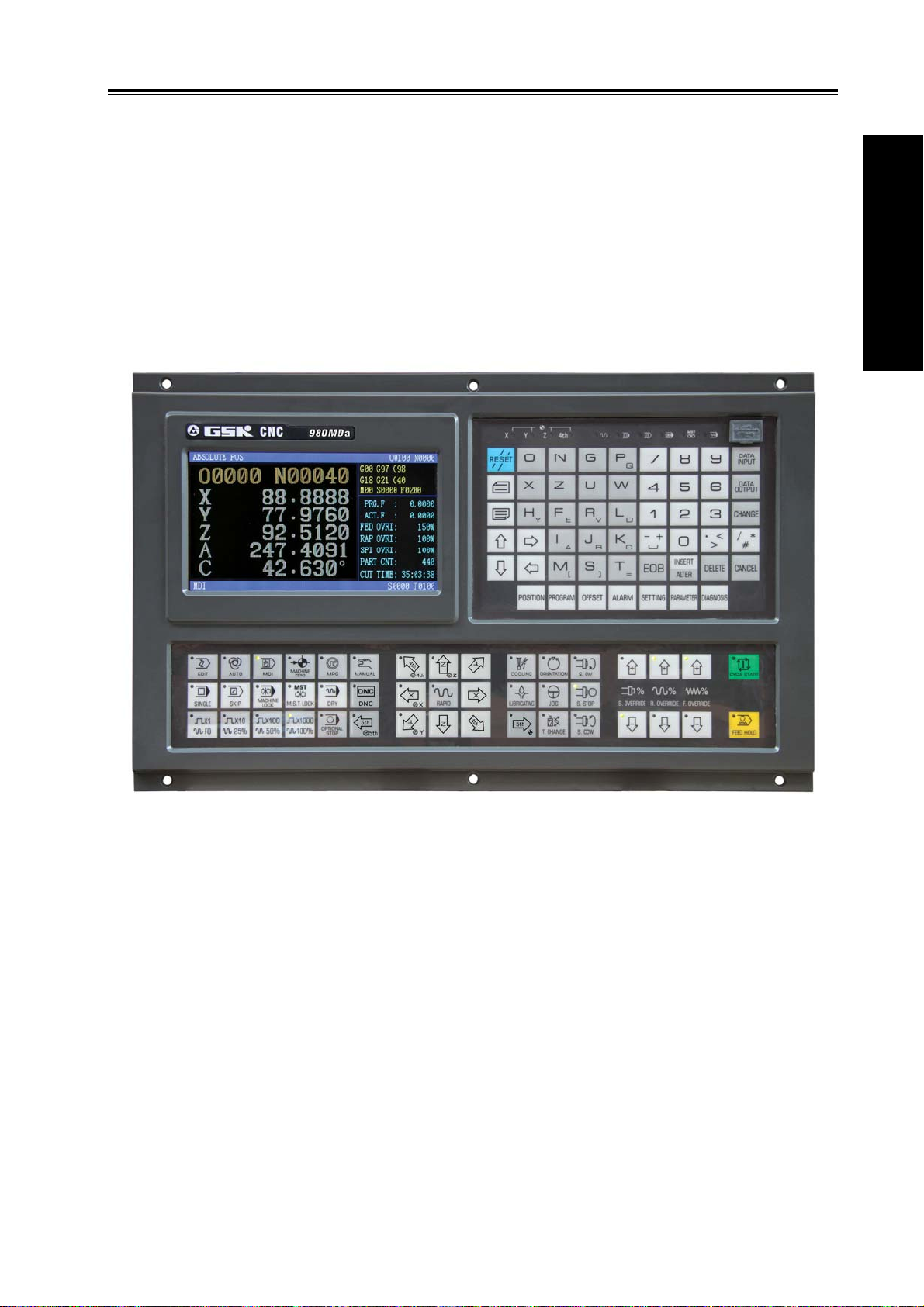
1.1 Panel Division.....................................................................................................................179
1.1.1 State Indication.........................................................................................................180
1.1.2 Edit Keypad..............................................................................................................180
1.1.3 Menu Display ...........................................................................................................181
1.1.4 Machine Panel .........................................................................................................182
1.2 Summary of Operation Mode .............................................................................................184
1.3 Display Interface.................................................................................................................185
1.3.1 Position Interface .....................................................................................................187
1.3.2 Program Interface ....................................................................................................190
1.3.3 Tool Offset, Macro Variable and Tool Life Management Interface ............................192
1.3.4 Alarm Interface .........................................................................................................195
1.3.5 Setting interface .......................................................................................................197
1.3.6 BIT PARAMETER, DATA PARAMETER, PITCH COMP Interface............................201
1.3.7 CNC DIAGNOSIS, PLC STATE, PLC VALUE, Machine Soft Panel, VERSION
MESSAGE Interface .........................................................................................................203
1.4 List of General Operations .................................................................................................205
CHAPTER 2 POWER ON OR OFF AND PROTECTION.............................................................. 211
2.1 System Power On ..............................................................................................................211
2.2 System Power Off ..............................................................................................................211
2.3 Overtravel Protection..........................................................................................................212
2.3.1 Hardware Overtravel Protection ............................................................................... 212
2.3.2 Software Overtravel Protection ................................................................................212
2.4 Emergency Operation ........................................................................................................212
2.4.1 Reset........................................................................................................................212
2.4.2 Emergency Stop.......................................................................................................213
2.4.3 Feed Hold.................................................................................................................213
2.4.4 Power Off .................................................................................................................213
CHAPTER 3 MANUAL OPERATION...............................................................................................214
3.1 Coordinate Axis Moving......................................................................................................214
3.1.1 Manual Feed ............................................................................................................214
3.1.2 Manual rapid traverse ..............................................................................................214
3.2 Feedrate Override Adjustment ...........................................................................................215
3.2.1 Manual Feedrate Override Adjustment..................................................................... 215
3.2.2 Manual Rapid Override Adjustment..........................................................................215
3.2.3 Spindle Override Adjustment....................................................................................216
3.3 Relative Coordinate Clearing .............................................................................................216
CHAPTER 4 MPG/STEP OPERATION ........................................................................................ 217
4.1 Step Feed...........................................................................................................................217
4.1.1 Increment Selection .................................................................................................217
4.1.2 Moving Direction Selection....................................................................................... 218
X

Contents
4.2 MPG (Handwheel) Feed.....................................................................................................218
4.2.1 Increment Selection..................................................................................................218
4.2.2 Moving Axis and Direction Selection ........................................................................219
4.2.3 Explanation Items.....................................................................................................219
CHAPTER 5 MDI OPERATION .......................................................................................................220
5.1 Code Words Input...............................................................................................................220
5.2 Code Words Execution.......................................................................................................221
5.3 Parameter Setting...............................................................................................................221
5.4 Data Modification................................................................................................................222
5.5 OUT Key Start ....................................................................................................................223
CHAPTER 6 PROGRAM EDIT AND MANAGEMENT .................................................................224
6.1
Program Creation
6.1.1 Creation of the Block Number ..................................................................................224
6.1.2 Input the Program Content .......................................................................................224
6.1.3 Search of the character ............................................................................................226
6.1.4 Insertion of the Character.........................................................................................228
6.1.5 Deletion of the Character .........................................................................................229
6.1.6 Modification of the Character....................................................................................229
6.1.7 Deletion of a Single Block ........................................................................................229
6.1.8 Deletion of the Blocks...............................................................................................229
6.1.9 Segment Deletion.....................................................................................................231
6.2 Program Annotation............................................................................................................232
6.2.1 Annotation for Program Name ..................................................................................232
6.2.2 Block Annotation.......................................................................................................233
6.2.3 Alter Program Annotation..........................................................................................234
6.3 Deletion of the Program......................................................................................................234
6.3.1 Deletion a Single Program .......................................................................................234
6.3.2 Deletion of All Programs ...........................................................................................234
6.4 Selection of the Program...................................................................................................234
6.4.1 Search Method .........................................................................................................235
6.4.2 Scanning method .....................................................................................................235
6.4.3 Cursor Method..........................................................................................................235
6.4.4 Select File by Using File List ....................................................................................236
6.5 Execution of the Program..................................................................................................236
6.6 Rename of the Program ....................................................................................................236
6.7 Copy of the Program ..........................................................................................................236
6.8 Program Positioning ...........................................................................................................237
6.9 Program Preview................................................................................................................237
...............................................................................................................224
CHAPTER 7 AUTO OPERATION................................................................................................239
7.1 Auto Run ...........................................................................................................................239
7.1.1 Selection of the Program To Be Run ........................................................................239
7.1.2 Program Start...........................................................................................................240
7.1.3 Stop of the Auto Run ................................................................................................240
7.1.4 Auto Run From an Arbitrary Block ............................................................................241
7.1.5 Adjustment of the feedrate override, rapid override..................................................242
XI

GSK980MDa Milling CNC System User Manual
7.1.6 Spindle override adjustment.....................................................................................243
7.2 DNC Running .....................................................................................................................243
7.3 Running State.....................................................................................................................243
7.3.1 Single Block Execution............................................................................................. 243
7.3.2 Dry Run....................................................................................................................244
7.3.3 Machine lock ............................................................................................................244
7.3.4 MST Lock.................................................................................................................244
7.3.5 Block Skip ................................................................................................................245
7.3.6 Optional Stop............................................................................................................245
7.4 Memorizing at Power-down................................................................................................245
7.4.1 Program Interruption in Non-DNC Auto Operation ...................................................245
7.4.2 Interruption at Power-down on DNC Auto Operation................................................246
CHAPTER 8 MACHINE ZERO RETURN OPERATION..................................................................247
8.1 Machine Zero .....................................................................................................................247
8.2 Machine Zero Return Steps ..............................................................................................247
CHAPTER 9 DATA SETTING, BACKUP and RESTORE ..............................................................248
9.1 Data Setting ......................................................................................................................248
9.1.1 Switch Setting ..........................................................................................................248
9.1.2 Graphic setting .........................................................................................................249
9.1.3 Parameter Setting ....................................................................................................250
9.2 The Password Setting and Alteration .................................................................................255
9.2.1 Entry of the Operation Level.....................................................................................256
9.2.2 Alteration of the Password........................................................................................257
9.2.3 Lower Level Set .......................................................................................................259
9.3 Operations under Different Operation Authorities...............................................................260
9.3.1 Operation of Communication....................................................................................260
9.3.2 CNC Operation.........................................................................................................261
9.3.3 Operation of File List ................................................................................................ 262
9.3.4 Advanced Operation of U-disk..................................................................................262
9.4 Data Restore and Backup ..................................................................................................26
3
CHAPTER 10 ADVANCE OPERATION........................................................................................265
10.1 Operation Path .................................................................................................................265
10.2 Operation instructions ......................................................................................................266
10.3 Attentions .........................................................................................................................267
CHAPTER 11 FLASH OPERATION..............................................................................................268
11.1. File List ............................................................................................................................268
11.2. Introduction of General File Operation Function ..............................................................269
11.2.1 Open and Close File Folder.................................................................................... 269
11.2.2 Copy the File by One Key(current list in C disk←→current list in U disk)...............270
11.2.3 CNC File Search ....................................................................................................271
11.2.4 Open CNC File .......................................................................................................271
XII

Contents
VOLUME Ⅲ INSTALLATION
CHAPTER 1 INSTALLATION LAYOUT........................................................................................275
1.1 GSK980MDa Connection ...................................................................................................275
1.1.1 GSK980MDa Back Cover Interface Layout ..............................................................275
1.1.2 Interface Explanation................................................................................................275
1.2 GSK980MDa Installation ....................................................................................................276
1.2.1 GSK980MDa External Dimensions ..........................................................................276
1.2.2 Installation Conditions of the Cabinet .......................................................................276
1.2.3 Protection Methods Against Interference..................................................................276
CHAPTER 2 DEFINITION&CONNECTION OF INTERFACE SIGNALS....................................279
2.1 Connection to Drive Unit.....................................................................................................279
2.1.1 Drive Interface Definition ..........................................................................................279
2.1.2 Command Pulse and Direction Signals ....................................................................279
2.1.3 Drive Unit Alarm Signal ............................................................................................279
2.1.4 Axis Enable Signal ENn............................................................................................280
2.1.5 Pulse Disable Signal SETn.......................................................................................280
2.1.6 Zero Signal nPC .......................................................................................................280
2.1.7 Connection to Drive Unit ..........................................................................................282
2.2 Connection of 4th Axis........................................................................................................282
2.2.1 4th Axis Interface Definition ......................................................................................282
2.2.2 Connection of 4th Axis Interface as Linear Axis........................................................283
2.2.3 Connection of 4th Axis Interface as Rotary Axis .......................................................284
2.3 Connection of Spindle Port.................................................................................................284
2.3.1 Definition of Signal ...................................................................................................284
2.3.2 Spindle Zero Signal ..................................................................................................285
2.3.3 Linear Axis................................................................................................................285
2.3.4 Connection of Spindle interface and Servo Spindle..................................................285
2.3.5 SVC Signal Explanation ...........................................................................................285
2.3.6 Explanations for ALM5(X5.3)....................................................................................286
2.4 Connection to Spindle Encoder ..........................................................................................286
2.4.1 Spindle Encoder Interface Definition ........................................................................286
2.4.2 Signal Explanation....................................................................................................286
2.4.3 Connection of Spindle Encoder Interface .................................................................286
2.5 Connection to Handwheel ..................................................................................................287
2.5.1 Handwheel Interface Definition.................................................................................287
2.5.2 Signal Explanation....................................................................................................288
2.6 Connection of GSK980MDa to PC .....................................................................................288
2.6.1 Communication Interface Definition..........................................................................288
2.6.2 Communication Interface Connection ......................................................................289
2.7 Connection of Power Interface ...........................................................................................289
2.8 I/O Interface Definition: ....................................................................................................290
2.8.1 Input Signal ..............................................................................................................292
2.8.2 Output Signal............................................................................................................293
2.9 Function of Standard Ladder Diagram................................................................................294
XIII

GSK980MDa Milling CNC System User Manual
2.9.1 Spindle Rotation Control........................................................................................294
2.9.2 Spindle Jog............................................................................................................295
2.9.3 Spindle Switching Volume Control.........................................................................296
2.9.4 Cycle Start and Feed Hold.....................................................................................297
2.9.5 Coolant Control......................................................................................................297
2.9.6 Lubrication Control ................................................................................................298
2.9.7 Block Skip..............................................................................................................299
2.9.8 Machine Lock ........................................................................................................299
2.9.9 Auxiliary Lock ........................................................................................................300
2.9.10 Single Block ...........................................................................................................300
2.9.11 Dry Run..................................................................................................................300
2.9.12 Optional Stop..........................................................................................................301
2.9.13 Stroke Limit and Emergency Stop..........................................................................301
2.9.14 Tri-colour Indicator .................................................................................................302
2.9.15 Reset and Cursor Return .......................................................................................302
2.9.16 Rigid Tapping ......................................................................................................... 302
2.9.17 Spindle Exact Stop.................................................................................................303
2.9.18 External MPG Control ............................................................................................304
2.9.19 Cs Axis Switching...................................................................................................304
2.10 Machine Zero ...................................................................................................................304
CHAPTER 3 PARAMETER.............................................................................................................314
3.1 Parameter Description (by Sequence) ...............................................................................314
3.1.1 Bit Parameter...........................................................................................................314
3.1.2 Data Parameter........................................................................................................324
3.2 Parameter Description (by Function Sequence).................................................................331
3.2.1 Axis Control Logic ....................................................................................................331
3.2.2 Acceleration & Deceleration Control.........................................................................333
3.2.3 Machine Protection ..................................................................................................335
3.2.4 Thread Function.......................................................................................................335
3.2.5 Spindle Control.........................................................................................................336
3.2.6 Tool Function............................................................................................................337
3.2.7 Edit and Display.......................................................................................................337
3.2.8 Precision Compensation ..........................................................................................338
3.2.9 Communication Setting............................................................................................339
3.2.10 Machine Zero Return .............................................................................................339
3.2.11 Rotary Axis Function...............................................................................................343
CHAPTER 4 MACHINE DEBUGGING METHODS AND STEPS................................................346
4.1 Emergency Stop and Stroke Limit......................................................................................346
4.2 Drive unit Unit Setting.........................................................................................................346
4.3 Gear Ratio Adjustment.......................................................................................................346
4.3.1 Servo Feed Axis.......................................................................................................346
4.3.2 Servo Spindle...........................................................................................................348
4.4 Acceleration&deceleration Characteristic Adjustment ........................................................349
4.5 Machine Zero Adjustment...................................................................................................350
4.6 Spindle Adjustment.............................................................................................................352
XIV

Contents
4.6.1 Spindle Encoder.......................................................................................................352
4.6.2 Spindle Brake...........................................................................................................352
4.6.3 Switch Volume Control of Spindle Speed.................................................................352
4.6.4 Analog Voltage Control for Spindle Speed................................................................352
4.7 Backlash Offset..................................................................................................................353
4.8 Step/MPG Adjustment........................................................................................................354
4.9 Other Adjustment................................................................................................................355
CHAPTER 5 DIAGNOSIS MESSAGE.........................................................................................356
5.1 CNC Diagnosis...................................................................................................................356
5.1.1 Signal Diagnosis from Machine to CNC...................................................................356
5.1.2 Axes Moving State and Data Diagnosis Signal of CNC............................................ 356
5.1.3 MDI Panel Keys Diagnosis.......................................................................................357
5.1.4 CNC Internal State...................................................................................................358
5.2 PLC State ...........................................................................................................................359
5.2.1 X Address (Fixed Addresses)...................................................................................359
5.2.2 Y Address (Fixed Addresses)...................................................................................361
5.3 PLC Data............................................................................................................................361
CHAPTER 6 MEMORIZING SCREW-PITCH ERROR COMPENSATION FUNCTION...................362
6.1 Function Explanation..........................................................................................................362
6.2 Specifications.....................................................................................................................362
6.3 Parameter Setting...............................................................................................................362
6.3.1 Screw-Pitch Compensation......................................................................................362
6.3.2 Screw-Pitch Error Origin...........................................................................................362
6.3.3 Offset Interval...........................................................................................................363
6.3.4 Compensation Value ................................................................................................363
6.4 Cautions for Offset Setting .................................................................................................363
6.5 Examples of Offset Parameters Setting..............................................................................364
XV

GSK980MDa Milling CNC System User Manual
APPENDIX
Appendix 1 Outline Dimension of GSK980MDa ...............................................................................371
Appendix 2 Dimensions of Additional Panel AP01............................................................................371
Appendix 3 Dimensions for Additional Panel AP02 ..........................................................................371
Appendix 4 Diagram of I/O Deconcentrator......................................................................................372
4.1 MCT01B .............................................................................................................................372
4.2 MCT01B-1..........................................................................................................................374
4.3 MCT05 ...............................................................................................................................375
Appendix 5 Explanations of Rigid tapping ........................................................................................375
5.1 Definition of Spindle Signal Line......................................................................................... 375
5.2 Wiring Diagram of the Spindle............................................................................................ 378
5.3 Setting of Spindle Electronic Gear Ratio ............................................................................379
5.4 Related Parameter Setting ................................................................................................. 380
Appendix 6 Communication Software GSKComm Instruction ..........................................................381
6.1 GSKComm Introduction .....................................................................................................381
6.2 Project Creation, Import and Removal ...............................................................................382
6.2.1 Project Creation ....................................................................................................... 382
6.2.2 Project Import........................................................................................................... 384
6.2.3 Project Removal....................................................................................................... 385
6.3 File Creation, Import, Removal and Edit.............................................................................385
6.3.1 File Creation............................................................................................................. 385
6.3.2 File Edit .................................................................................................................... 386
6.3.3 Add Files .................................................................................................................. 388
6.3.4 File Removal ............................................................................................................ 389
6.4 File Download (PC→CNC).................................................................................................389
6.5 View Tool Compensation and Pitch Error Compensation ...................................................392
6.6 DNC Transmission .............................................................................................................393
6.7 CNC Part Programs Management......................................................................................394
6.8 Preparations before Communication .................................................................................. 395
6.9 Communication between CNC and CNC ...........................................................................396
Appendix 7 Alarm Message..............................................................................................................398
Appendix 8 Notes for the Ladder Diagram of the GSK980MDa Software ( Post Version
V3.03 ,including V3.03) ....................................................................................................................406
Appendix 9 Standard Ladder Diagram .............................................................................................407
XVI

Contents
VOLUME I PROGRAMMING
1

GSK980MDa Milling CNC System User Manual
2
Chapter 1 Programming Fundmentals
CHAPTER 1 PROGRAMMING FUNDMENTALS
1.1 Introduction
GSK980MDa Milling Machine is a new generation of CNC system developed by GSK Company.
As the upgraded version of GSK980MD, it supports milling, boring and drilling cycle. It employs 32 bits
high-capability CPU and very large scale programmable device FPGA, applies real-time multi-task
control technology and hardware interpolation technology, and is able to perform μm level precision
motion control and PLC logic control. GSK980MDa is the optimum choice for upgrading CNC milling
machine.
Volume I Programming
Characteristics:
9 Five axes control (X, Y, Z ,4th and 5th); 3 axes linkage; optional interpolation precision
(1μm/0.1μm); maximum speed 60m/min; optional axis types (linear axis or revolving axis)
for the 4th and 5th axes; CS axis control available for the 4th and 5th axes.
9 Electronic gear ratio: (1~32767):(1~32767)
9 Screw-pitch error compensation, backlash compensation, tool length compensation, tool
abrasion compensation and tool nose radius compensation.
9 Embedded with PLC can be downloaded to CNC from PC.
9 DNC function supports for real-time program transmission for machining.
9 Compatible with G commands in GSK980MC, GSK928MA and GSK980MD. 26 kinds of
canned cycles, such as drilling/boring, circular/rectangular groove rough-milling, full
circle/rectangular finish-milling, linear/rectangular/arc continuous drilling.
9 Spindle encoder tapping and rigid tapping can be detected during tapping cycle, so that
high precision machining can be performed.
9 Metric/inch programming; automatic chamfering function and tool life management function.
9 Chinese, English, Russian and Spanish display selected by the parameters.
3
9 Full screen program editing; 40MB program capacity for storing up to 40000 of part
Volume I Programming
programs.
9 USB data communication; CNC system upgrading, machining programs reading through U
disk and bidirectional transfer between CNC and U disk.
9 Alarm log; multi-level passwords for equipment maintenance and management.
9 Bidirectional transfer between CNC and CNC, CNC and PC; upgrade of CNC software and
PLC programs;
9 The installation dimensions and the electric ports are compatible with GSK980MD,
GSK980MC.
Specifications
Motion control
GSK980MDa Milling CNC System User Manual
Controlled axes: five axes (X,Y,Z,4th and
optional axis types (linear axis or revolving axis) and CS contouring control
available;
Interpolation functions: linear interpolation (for X, Y, Z, 4th and 5th axes);
helical interpolation (for X, Y and Z axes); circular interpolation (for arbitrary 2
axes).
Position command range: -99999999~99999999; least command increment:
1μm/0.1μm; (selected via parameters)
Electronic gear ratio: command multiplier 1~32767, command frequency
divisor 1~32767
Rapid traverse speed: maximum 60000mm/min
Rapid traverse override: F0, 25%, 50%, 100% four levels real-time tuning
Cutting feedrate: maximum 15000mm/min (feed per min.) or 500mm/r. (feed
per rotation)
Feedrate override: 0~150% sixteen-level real-time tuning
5th); (for the 4th and 5th axes)
G Code
Macro
command
Operation
mode
Tapping
Manual feedrate: 0~1260mm/min sixteen-level real-time tuning
MPG feed: 0.001, 0.010, 0.100,1.000mm four gears.
Acceleration/deceleration type: S-type for rapid traverse; exponential-type for
cutting feed.
Automatic chamfering
65 kinds of G codes:G00, G01, G02, G03, G04, G10, G11, G17, G18, G19,
G20, G21, G28, G29, G30, G31, G40, G41, G42, G43, G44, G49, G54, G55,
G56, G57, G58, G59, G65, G66, G67, G73, G74, G80, G81, G82, G83, G84,
G85, G86, G88, G89, G90, G91, G92, G94, G95, G98, G99, G110, G111,
G112, G113, G114, G115, G134, G135, G136, G137, G138, G139, G140,
G141, G142, G143
31 kinds of arithmetic, logical operations and skip can be achieved by macro
command G65
Macro statement command. eg: IF, WHILE, GOTO
Seven operation modes: EDIT, AUTO, MDI, DNC, MACHINE ZERO,
MPG/STEP and MANUAL.
Tapping function: lead 0.001~500mm or 0.06~25400 pitch/inch
Encoder tapping: settable line number of encoder(0 or100p/r~5000p/r); no
detect for spindle encoder (when the line number is set to 0)
4

Precision
compensation
M command
T command
Spindle speed
control
PLC function
Display
interface
Program edit
USB
Chapter 1 Programming Fundmentals
Rigid tapping: by rotary axis
Drive ratio between encoder and spindle:(1~255):(1~255)
Backlash compensation: 0~2.000mm
Pitch error compensation: 255 compensation points per axis; compensation
amount of each point: ±0.255mm.
Tool compensation: 32 groups tool length compensation, tool wear
compensation, cutter compensation C
Special M commands (redefinition unallowed): M02,M29, M30, M98,
M99,M9000~M9999.
Other M □□ commands are defined or disposed by PLC program.
M commands defined by standard PLC program: M00, M03, M04, M05 M08,
M09, M10, M11, M32, M33
tool number T01~T32 (32 numbers at most); manual tool change or auto-tool
change selected by the parameters; auto tool change sequence set by PLC
program.
Tool life management; 32 groups, 8 kinds/groups of tool life management data
Speed switching value control: S □□ command is defined or disposed by PLC
program; the standard PLC programs S1, S2, S3 and S4 directly output; The
output of S1,S2, S3, and S4 are closed by S0.
Speed analog voltage control: the spindle speed per minute commanded by S
codes; output 0~10V voltage to spindle converter; spindle stepless speed
changing supports 4 spindle mechanical gears
9 kinds of basic commands; 23 kinds of function commands; 2-level PLC
program involving up to 5000 steps (2μs processing time for each step). 8ms
refresh cycle for the first level program; Ladder diagram edit software and
communication software downloadable
Integrated machine panel: 44 points input (key), 44 points output (LED)
Basic I/O: 41 points input/ 36 points output
Displayer: 480×234 lattice, 7’’ wide-screen multi-color LCD,
Display modes: Chinese, English, Russian, Spanish display selected by
parameters; machining path displayable
Capacity: 40MB for up to 40000 part programs; custom macro program call; 4
nesting-levels of subprogram
Edit modes: full-screen editing; absolute/incremental programming
CNC system upgrade
Part programs reading in USB
Bidirectional files transfer between CNC and USB (including programs,
parameters, PLC backup and recovery)
Volume I Programming
Clock display Clock, date and week display.
Serial
Communication
Matching drive
unit
Bidirectional transfer between CNC and PC, CNC and CNC (involving
programs, parameters, tool compensation data); download and upgrade of
system software and PLC program serial ports
AC servo or step drive device by using the pulse+direction signal input. (DA98
or DY3 series)
5
G Code Table
Volume I Programming
Code Function Code Function Code Function
G00
*G01 Linear interpolation G55
G02
G03
G04 Dwell, exact stop G58
G10
G11
*G17 XY plane selection G66
G18 ZX plane selection *G67
G19 YZ plane selection G73 High-speed peck drilling G114
G20 Inch input G74 Counter tapping cycle G115
G21 Metric input *G80 Canned cycle cancel G134
G28
G29
G30
G31 Skip function G84 Tapping cycle G138
*G40
G41
G42
G43
Positioning (rapid
traverse)
Circular/helical
interpolation (CW)
Circular/helical
interpolation (CCW)
Tool life
management
Tool life
management end
Reference position
return
Return from
reference position
2nd, 3rd, 4th,
reference position
return
Cutter
Compensation
cancel
Cutter
compensation left
Cutter
compensation right
Tool length
compensation +
direction
GSK980MDa Milling CNC System User Manual
*G54
G56
G57
G59
G65
G81
G82
G83 Peck drilling cycle G137
G85 Boring cycle G139
G86 Drilling cycle G140
G88 Boring cycle G141
G89 Boring cycle G142
Workpiece coordinate
system 1
Workpiece coordinate
system 2
Workpiece coordinate
system 3
Workpiece coordinate
system 4
Workpiece coordinate
system 5
Workpiece coordinate
system 6
Macro program/ macro
code
Macro program modal
call
Macro program modal
call cancel
Drilling cycle (spot
drilling cycle)
Drilling cycle (stepped
hole boring cycle)
G92 Coordinate system setting
*G94 Feed per min.
G95 Feed per rotation
*G98
G99
G110
G111
G112 Inner circle finishing (CCW)
G113 Inner circle finishing (CW)
G135
G136
Return to initial plane in
canned cycle
Return to R point in canned
cycle
Inner circle groove
roughing (CCW)
Inner circle groove
roughing (CW)
Circular outer finish milling
(CW)
Outer circle finishing
(CCW)
Rectangular groove
roughing (CCW)
Rectangular groove
roughing (CW)
Rectangular groove inner
finishing (CCW)
Rectangular groove inner
finishing (CW)
Rectangular outer finishing
(CCW)
Rectangular outer finishing
(CW)
Rectangular continuous
drilling (CW)
Rectangular continuous
drilling (CCW)
Arc continuous drilling
(CW)
6

Chapter 1 Programming Fundmentals
Tool length
G44
*G49
Note: mark “ * ” means initial state.
PLC Codes List
Code Function Code Function Code Function
LD Normal open contact
LDI Normal closed
OUT Output coil CMP Comparison setting SUBB Binary subtraction
AND Normal open contact
ANI Normal closed
OR
ORI Normal closed
ORB Serial block in
ANB Parallel block in
END1
END2
compensation –
direction
Tool length
compensation
cancel
read
contact read
in series
contact in series
Normal open contact
in parallel
contact in parallel
parallel
series
First level program
end
Second level
program end
*G90
G91
Absolute
programming
Incremental
programming
SET Setting SPE Subprogram end
RST Resetting ADDB Binary addition
CTRC Counter ALT Alternative output
TMRB Timer DIFU Differential up
CODB
ROTB
MOVN Data copy PARI Parity check
DECB Binary decode LBL Program skip numbering
JMPB Jump CALL Subprogram call
SP
Binary code
transformation
Binary rotational
control
Subprogram
numbering
G143
DIFD Differential down
MOVE Logical AND
Arc continuous drilling
(CCW)
Volume I Programming
1.2 Program Execution
1.2.1 Program Execution Sequence
The current program can only be run in automatic mode. GSK980MDa cannot run more than 1
program at the same time, so only one program can be performed at a time. The cursor is ahead of the
first block when a program is opened, and can be moved in EDIT mode. In automatic mode, when the
machine is in stop state, the cycle start signal ( key on the panel or external cycle start signal)
enables the program to be run from the block where the cursor is located. Usually, blocks are executed
in sequence programmed in advanced. Program stops running till M02 or M30 is executed. The cursor
moves along with program execution. The program execution sequence or state will be changed in
following conditions:
7
GSK980MDa Milling CNC System User Manual
Volume I Programming
z Program running stops when key or the Emergency Stop button is pressed;
Program running stops when the CNC alarm or PLC alarm occurs;
z When the system is switched in EDIT or MDI mode, program stops running after the current
block is executed. After switching to automatic mode again, when
is pressed or external cycle start signal is ON, the program runs from the block where the
cursor is located.
z If the operation mode is switched to MANUAL/MPG/STEP/MACHINE ZERO RETURN
mode when the program is running, the execution dwells; after switching to automatic mode
again, when
program runs from where it stops.
z The execution dwells when
program starts running from where it stops when
external cycle start signal is ON;
z The program dwells at the end of each block when the single block switch is on; after
pressing key or switching on external cycle signal, program continuously runs from
the next block;
z Blocks with mark “/” is skipped when the skip switch is ON.
z The object block is executed when command G65 or macro program skip (GOTO) is
specified.
z When M98 or M9000~M9999 command is performed, the corresponding subprogram or
macro program is called; M99 is executed at the end of the subprogram or macro program,
after returning to the main program, the subsequent block (the one after the block in which
the subprogram is called) is executed. (return to a specified block, if it is commanded by
M99);
z When M99 command is specified in the middle of a main program which is not called by
other programs, the current program is repeatly executed after returning to the head of the
program.
key on the panel
key on the panel is pressed or external cycle start signal is ON, the
key is pressed or external pause signal is cut off;
key on the panel is pressed or
1.2.2 Word Execution Sequence within Block
When multiple words (such as G, X, Y, Z, F, R, M, S, T,) are in one block, most of M, S, and T
words are interpreted by NC and sent to PLC for processing. Other words are processed by NC
directly. M98, M99, M9000~M9999 and S word (which specify the spindle speed in r/min, m/min) are
directly processed by NC as well.
When G words share the same block with M00, M01, M02 and M30, M words are executed after
G words, and NC sends corresponding signals to PLC for processing.
When the G words share the same block with the M98, M99, M9000~M9999, these M words are
performed by NC after G words (the M signal not sent to PLC).
When G words and M, S, T words share the same block, PLC program (ladder diagram)
determines the execution consequence (executed at the same time or G words before M, S, T words).
Refer to the manual from tool builder for relevant words execution sequence.
8
Chapter 1 Programming Fundmentals
1.3 Basic Axes Increment System
The increment system consists of the least input increment (for input) and least command
increment (for output). The least input increment is the minimum unit for programming moving
distance. The least command increment is the minimum unit for moving the tool on the machine. Both
increments are represented in mm,inches.or deg.
The basic axes herein means X, Y, Z axes. The basic increment system includes IS-B and IS-C
types which can be selected by bit ISC of parameter NO.038.
038 ISC
ISC =1:The increment system is IS-C(0.1μ);
=0:The increment system is IS-B(1μ)
In different increment system, different pulse output type enables different output speed.
(Selected by bit ABPx of parameter NO.039)
039 ABP5 ABP4 ABPZ ABPY ABPX
ABPx =1:The impulse mode of axis is AB phases;
=0:The impulse mode of axis is impulse and direction.
Volume I Programming
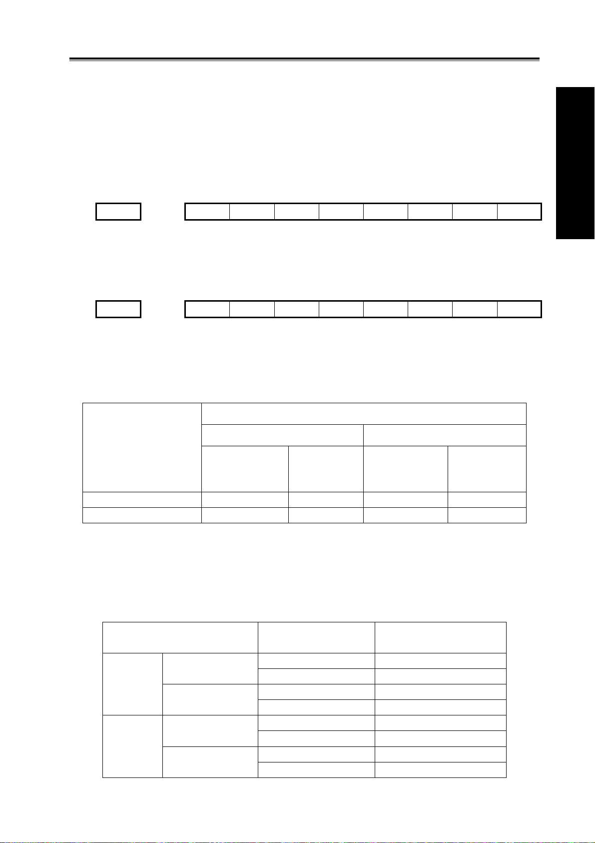
1.3.1 Speed of Increment Systems
Output mode
Metric machine
system
(mm/min)
Pulse + direction 60,000 6,000 6,000 600
AB quadrature phase 240,000 24,000 24,000 2,400
1μ(IS-B) 0.1μ(IS-C)
Inch machine
system
(inch/min)
Speed
Metric machine
system
(mm/min)
Inch machine
system
(inch/min)
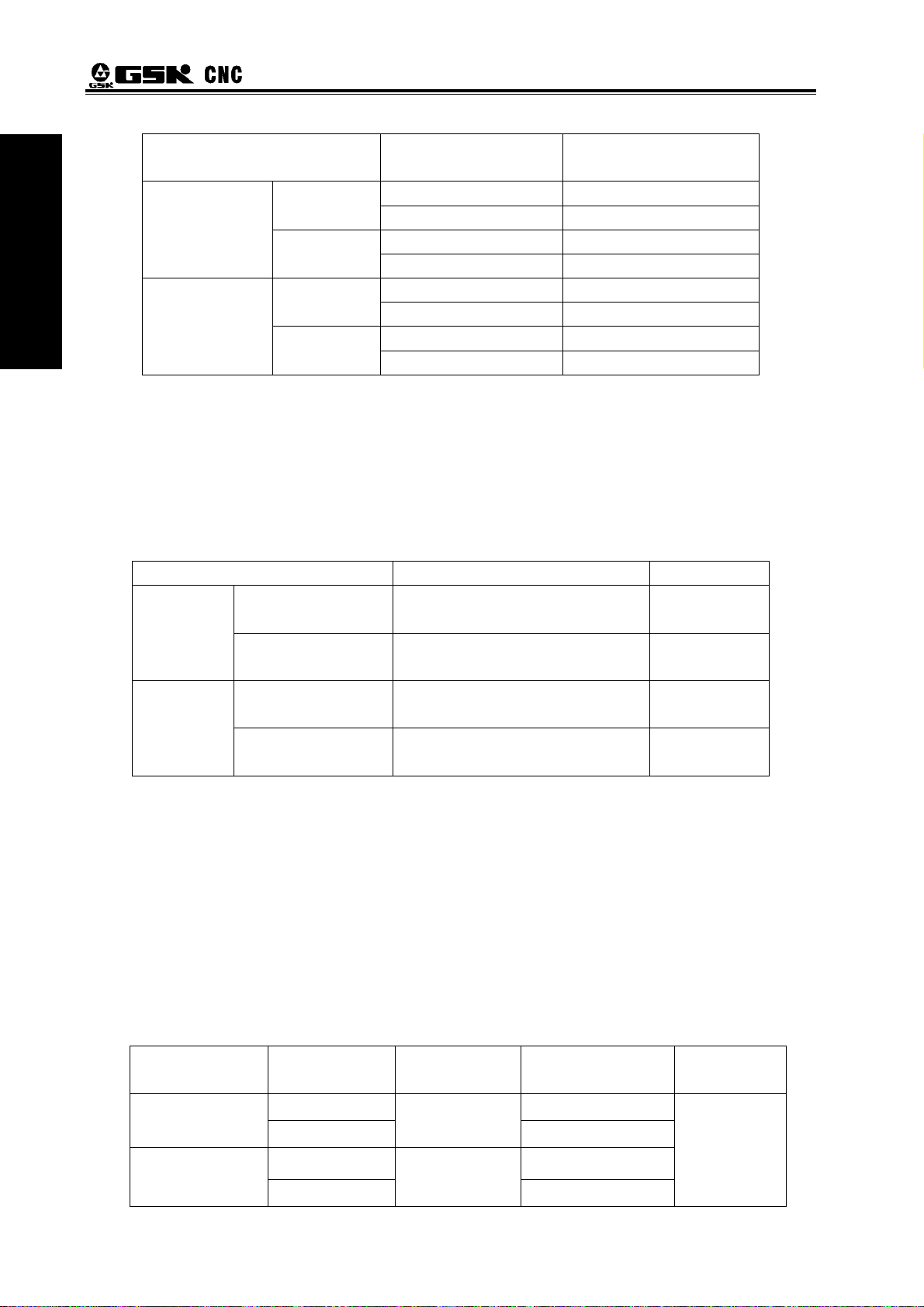
1.3.2 Unit of Increment Systems
In different increment system, the least input/output increment varies with metric/inch system.
The specific data is shown as follows:
Metric
machine
system
Inch
machine
system
1μ(IS-B)
Metric input (G21)
Inch input (G20)
Metric input (G21)
Inch input (G20)
Least input
increment (for input)
0.001 (mm) 0.001 (mm)
0.001 (deg) 0.001 (deg)
0.0001 (inch) 0.001 (mm)
0.001 (deg) 0.001 (deg)
0.001 (mm) 0.0001 (inch)
0.001 (deg) 0.001 (deg)
0.0001 (inch) 0.0001 (inch)
0.001 (deg) 0.001 (deg)
Least command
increment (for output)
9
Volume I Programming
Metric machine
system
Inch machine
system
Least input increment (for input) is metric or inch can be set by G20 or G21.
Least command increment (for output) is metric or inch is determined by machine tool and set by
bit SCW of parameter NO.004.
1.3.3 Data Ranges of Increment System
Limited by pulse output frequency, the data ranges may vary due to different increment system.
Increment system Command data input ranges Data format
1 u(IS-B)
0.1μ(IS-C)
Note:5.3 in the table above indicates 5 integers and 3 decimals. Other data are alike.
0.1μ(IS-C)
(G21)
Inch input
(G20)
(G21)
Inch input
(G20)
Metric input (G21)
Inch input (G20)
Metric input (G21)
Inch input (G20)
GSK980MDa Milling CNC System User Manual
Least input
increment (for input)
0.0001 (mm) 0.0001 (mm) Metric input
0.0001 (deg) 0.0001 (deg)
0.00001 (inch) 0.0001 (mm)
0.0001 (deg) 0.0001 (deg)
0.0001 (mm) 0.00001 (inch) Metric input
0.0001 (deg) 0.0001 (deg)
0.00001 (inch) 0.00001 (inch)
0.0001 (deg) 0.0001 (deg)
-99999.999 ~ 99999.999 (mm)
-99999.999 ~ 99999.999 (deg)
-9999.9999 ~ 9999.9999 (inch)
-9999.999 ~ 9999.999 (deg)
-9999.9999 ~ 9999.9999 (mm)
-9999.9999 ~ 9999.9999 (deg)
-999.99999 ~ 999.99999 (inch)
-999.9999 ~ 999.9999 (deg)
Least command
increment (for output)
5.3
5.3
4.4
4.3
4.4
4.4
3.5
3.4
1.3.4 Data Ranges and Unit of Increment System
z Speed parameter
Machine tool types decide the units of linear axes speed, i.e. mm/min for metric machine system
is; 0.1inch/min for inch machine system.
The range of linear axis speed parameter is codetermined by machine tool type and increment
system.
For example: data parameter NO.070: upper limit of cutting feedrate.
10
Machine tool
type
Metric machine
system
Inch machine
system
Increment
system
1 μ(IS-B)
0.1μ (IS-C)
1 μ(IS-B)
0.1μ(IS-C)
Linear axis
speed unit
mm/min
0.1inch/min
Parameter range
Rotary axis
speed unit
10~ 60000
10~ 6000
deg/min
5~60000
5~6000
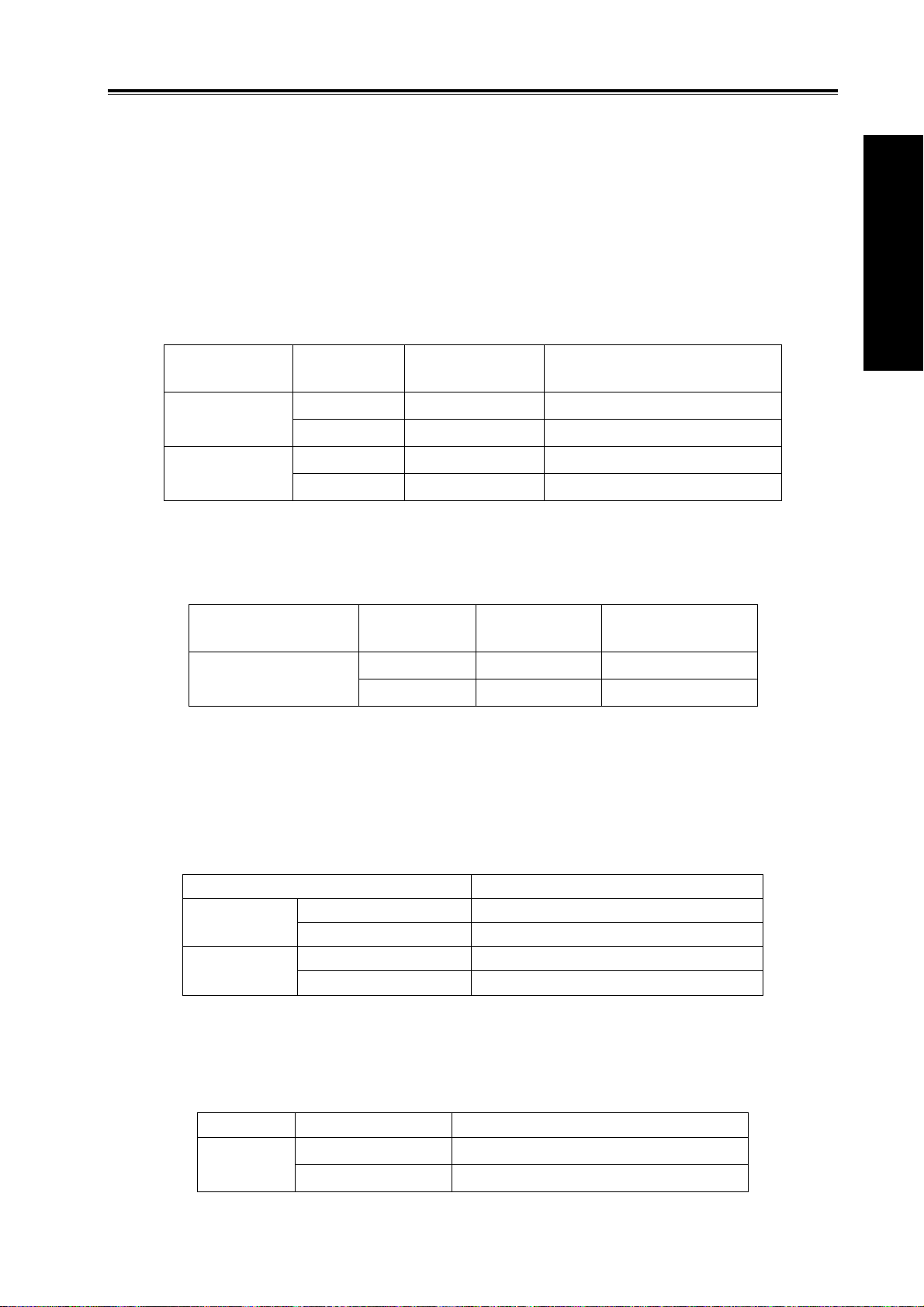
Chapter 1 Programming Fundmentals
As rotary axes are not involved in metric-inch interconversion, the rotation speed unit is always
deg/min.
The switch between different increment systems may cause the excess of permitted running
speed set by data parameter. Therefore, at the first power-on after switching, the system
automatically modifies relevant speed parameters and gives an alarm.
z Increment parameter
The unit and range of linear axis speed parameter are codetermined by machine tool type and
increment system.
For example: parameter NO135: X axis software limit.
Machine tool
type
Metric machine
system
Inch machine
system
As rotary axes are not involved in metric-inch interconversion, the rotary axis increment
parameter unit is determined by increment system types. The ranges of rotary axis increment
parameters are the same as that of metric machine tool.
Machine tool type
Metric, inch machine
tool system
z Coordinate data(G54~G59)
The unit of linear axis coordinate data is determined by metric/inch input system, namely, mm for
metric system, inch for inch system.
The ranges of linear axis coordinate data are codetermined by metric/inch input system and
increment system. It is the same as command data input ranges. Shown as follows:
1 μ(IS-B)
0.1μ(IS-C)
As rotary axis is not involve in metric-inch interconversion, the unit of rotary axis coordinate data
is deg. The ranges of rotary axis coordinate data is the same as linear axis coordinate data ranges in
metric system.
Input type Increment system Rotary axis coordinate data range
Metric,
inch input
Increment
system
1 μ(IS-B)
0.1μ(IS-C)
1 μ(IS-B)
0.1μ(IS-C)
Increment system Linear axis coordinate data range
Metric input (G21) -99999.999 ~ 99999.999(mm)
Inch input (G20) -9999.9999 ~ 9999.9999(inch)
Metric input (G21) -9999.9999 ~ 9999.9999(mm)
Inch input (G20) -999.99999 ~ 999.99999(inch)
1 μ(IS-B) -99999.999 ~ 99999.999(deg)
0.1μ(IS-C)
Linear axis
increment unit
0.001mm
0.0001 mm
0.0001inch
0.00001 inch
Increment
system
1 μ(IS-B)
0.1μ(IS-C)
-9999.9999 ~ 9999.9999(deg)
Linear axis parameter range
-99,999.999~ 99,999.999
-9,999.9999~ 9,999.9999
-9,999.9999~ 9,999.9999
-999.99999~ 999.99999
Rotation axis
speed unit
0.001deg
0.0001 deg
Rotation axis
parameter range
0~ 99999.999
0~ 9999.9999
Volume I Programming
11
z Tool compensation data
Volume I Programming
The unit of tool compensation data is determined by metric/inch input system, namely, mm for
metric input, inch for inch input.
The range of tool compensation data is limited as 9999999, determined by inch input system and
increment system. It is smaller than command data. Shown as follows:
Input type
Metric input
(G21)
Increment
system
1 μ(IS-B)
0.1μ(IS-C)
GSK980MDa Milling CNC System User Manual
Tool compensation
data unit
mm
Tool compensation
data range
±9999.999
±999.9999
Metric input
(G21)
z Screw-pitch error compensation data
The unit and range of linear axis screw-pitch error compensation data is codetermined by
machine tool type and increment system.
Shown as following table:
Machine tool
type
Metric tool
machine system
Inch tool
machine system
Rotary axes are not involved in metric-inch conversion. The unit of rotary axes screw-pitch error
compensation is determined by increment system. The range is the same as that of the metric
machine tool.
Machine tool
system
Metric, inch
machine system
z Graphic setting data
The maximum and minimum data ranges of X, Y, Z set by graph is in accordance with the
command data ranges.
Increment system Graphic setting X,Y,Z ranges
1 μ(IS-B)
0.1μ(IS-C)
1 μ(IS-B)
0.1μ(IS-C)
Increment
system
1 μ(IS-B)
0.1μ(IS-C)
1 μ(IS-B)
0.1μ(IS-C)
Increment
system
1 μ(IS-B)
0.1μ(IS-C)
Metric input (G21) -99999.999 ~ 99999.999 (mm)
Inch input (G20) -9999.9999 ~ 9999.9999 (inch)
Metric input (G21) -9999.9999 ~ 9999.9999 (mm)
Inch input (G20) -999.99999 ~ 999.99999 (inch)
Linear axis screw-pitch
error compensation data
unit
0.001mm
0.0001mm
0.0001inch
0.00001inch
Rotary axis
screw-pitch error
compensation unit
0.001deg
0.0001 deg
inch
±999.9999
±99.99999
Linear axis screw-pitch
error compensation data
range
-255~255
-2550~2550
-255~255
-2550~2550
Rotary axis
screw-pitch error
compensation range
0~255
0~2550
12

Chapter 1 Programming Fundmentals
1.3.5 The Units and Ranges of Program Address Values
z Definition and ranges of the pitch :
z Speed F definition
Code
F 0.001~500.000 0.0001~500.00 mm/pitch [lead] Input in metric
(G21)
Inch input(G20)
G94: feed per minute, F unit: mm/min
G95: feed per rotation, F definition and ranges are as follows:
Metric input(G21)
Inch input(G20)
I 0.06~25400 0.06~2540 Pitch[lead]/inch
F 0.0001~50.00 0.00001~50.0 inch//pitch [lead]
I 0.06~2540 0.06~254 Pitch[lead]/inch
1 μ(IS-B) 0.1μ(IS-C)
1 μ(IS-B) 0.1μ(IS-C)
0.001~500.000 0.0001~500.0000 mm/rev
0.0001~50.0 0.00001~50.0 inch/rev
Unit
Unit
1.4 Additional Axes Increment System
Volume I Programming
In the least increment system (IS-B or IS-C), under the condition that the additional axes are not
involved in simultaneous control and just used for separate motion (such as feeding), and the
requirement for precision is not high, when the least increment is 0.01, the feedrate will be much
faster, greatly increasing the efficiency. Therefore, the additional axes least increment system is not
necessary to be in accordance with the current least increment system. To meet various requirements
of users, the system adds optional function to least increment system.
Additional axes increment system is set by state parameter No.026, No.028. Shown as follows:
026 A4IS1 A4IS0 RCS4 ROS4 ROT4
A4IS1, A4IS0:Select increment system of 4th.
A4IS1 A4IS0 Increment System of 4TH Least input/output
0 0 Same to the X, Y, Z
0 1 IS-A 0.01
1 0 IS-B 0.001
1 1 IS-C 0.0001
028 A5IS1 A5IS0 RCS5 ROS5 ROT5
A5IS1, A5IS0:Select increment system of 5th.
A5IS1 A5IS0 Increment System of 5TH Least input/output
0 0 Same to the X, Y, Z
0 1 IS-A 0.01
1 0 IS-B 0.001
1 1 IS-C 0.0001
Note: the least input/output in the table above are described without considering the metric/inch system and
rotation axes.
13

GSK980MDa Milling CNC System User Manual
Volume I Programming
When IS-B or IS-C is selected, the speed and range of additional axes are the same as
described in 1.3.
1.4.2 Additonal Axes in IS-A Increment System
When IS-A is selected, the maximum speed of additional axes can reach 100 times of that of
IS-B and IS-C. The relevant data and parameters ranges are the same as that of the current basic
axes increment system. (Refer to section 1.3)
1.4.1 Additional Axes in Current Increment System
14

Chapter 2 MSTF Codes
y
y
CHAPTER 2 MSTF CODES
2.1 M Codes (Miscellaneous Function)
The M codes are composed by code address M and 1~2 or 4 digits after the codes M is used
for controlling the program execution or outputting M code to PLC.
M □□□□
M98, M99 and M9000~M9999 are independently processed by CNC, and the M codes are not
output to PLC.
The function of M29 is fixed, namely, to output M codes to PLC.
The M02 and M03 are defined as program END codes by NC, meanwhile it also outputs M codes
to PLC for the I/O control (spindle OFF, cooling OFF control etc.).
The PLC program can not change the meaning of the above-mentioned codes when the M98,
M99 and M9000~M9999 are regarded as program CALL codes and the M02 and M30 are regarded
as program END codes. The codes of other M codes are all output to PLC program for specifying
the code function; please refer to the manual issued by machine tool manufacturer.
One block only has one M code. The CNC alarm occurs when two or more M codes are existed
in one block.
Codes value (00~99, 9000~9999,leading zero can be omitted)
Address
Table 2-1 M code table for program execution
Codes Functions
M02
M29
M30
M98
M99
M9000~M9999
Return from the subprogram; the program will be repeatedl
executed. If the code M99 is used for main program ending (namel
the current program is not called by other programs).
Call macro program (Program No. is larger than 9000)
Rigid tapping designation
End-of-Run
End-of-Run
Subprogram call
Volume I Programming
2.1.1 End of Program (M02)
Format: M02
Function: The M02 code is executed in the Auto mode. The automatic run is ended after the other
codes of current block are executed; the cursor stops in the block in which the M02 is located
and does not return to the head of the program. If the program is to be executed again, the
cursor should return to the beginning of the program.
Besides the above-mentioned functions processed by CNC, the functions of code M02 also can
be defined by the PLC ladder diagram. The function defined by standard ladder diagram can be:
the current input state of CNC is not change after the code M02 is executed.
15

GSK980MDa Milling CNC System User Manual
e
Volume I Programming
Format:M29
Function:In auto mode, after the execution of M29, the G74, G84 that followed is processed as rigid
tapping codes.
2.1.3 End of Run (M30)
Format: M30
Function: If M30 command is executed in the Auto mode, the automatic run is ended after the other
commands of current block are executed; the system cancels the tool nose radius
compensation and the cursor returns to the beginning of the program when the workpieces
number is added by one (whether the cursor returns to the head of the program is
determined by parameters).
The cursor does not return to the beginning of the program when the BIT4 of parameter No.005
is set to 0; when it is set to 1, the cursor returns to the beginning of the program as soon as the
program execution is finished.
Besides the above-mentioned functions processed by CNC, the functions of code M30 also can
be defined by the PLC ladder diagram. The function defined by standard ladder diagram can be:
turn OFF the M03, M04 or M08 output signal after the M30 command is executed, and meanwhile
output M05 signal.
2.1.2 Rigid Tapping Designation M29
2.1.4 Subprogram Call (M98)
Format:M98 P○○○○□□□□
Function: In Auto mode, when the M98 is executed, the subprogram specified by P is called after the
execution of other codes in the current block. The subprogram can be performed 9999 times
at most. M98 cannot be performed in MDI, or an alarm will occur.
The called subprogram No.(0000~9999).The
subprogram can be omitted when the called times are not input; th
subprogram No. should be 4 digits when the called times is input;
Called times(1-9999),calling for once,
the
input can be omitted
leading zero of
2.1.5 Return from Subprogram (M99)
Format: M99 P○○○○
Function: (in subprogram) as the other commands of current block are executed, the block specified
by P is performed continuously when the main program is returned. The next
block is performed continuously by calling current subprogram of M98 command when
returning to the main program; because of the P is not given. If the main program is ended
by using the M99 (namely, the current program is not called by other programs for
execution), the current program will be run circularly. So, the M99 command is disabled in
MDI.
The block No. (0000~9999) when return to main program is
executed, the leading zero can be omitted.
16

Chapter 2 MSTF Codes
Example: Fig. 2-1 shows that the execution route of the subprogram is called (the P command within
M99). Fig. 2-2 shows that the execution route of the subprogram is called (the P command
is not in M99.
Volume I Programming
This GSK980MDa can calls quadruple subprogram, namely, the other subprogram can be called
from the subprogram. (See Fig. 2-3)
Main program
O1 001 ;
...
...
...
M98P10 02;
...
...
...
...
M30;
Subprogram
O1002;
...
...
...
M 98P 100 3;
...
...
...
...
M99;
Level 1
Subprogram
O1 003 ;
...
...
...
M98P10 04;
...
...
...
...
M99;
Level 2
Subprogram
O1004;
...
...
...
M 98P 100 5;
...
...
...
...
M99;
Level 3
Subprogram
O1005;
...
...
...
...
...
...
...
...
M99;
Le vel 4
Fig. 2-3 subprogram nestifications
17

GSK980MDa Milling CNC System User Manual
Volume I Programming
2.1.6 Macro Program Call (M9000~M9999)
Format : M □□□□
9000~9999
Command function: Call the macro program which is corresponded by the command value
(O9000~O9999).
Macro program: Program 09000~09999 is special space obligated for the machine tool
manufacturer for using editing and achieving special function subprogram, which is called macro
program. Two-level operation authority is needed when editing the program 09000~09999, the user
can not modify or run the macro program but the macro calling command if his authority is 3~5 level.
So the M9000~M9999 commands are invalid in MDI mode.
2.1.7 M Command Defined by Standard PLC Ladder Diagram
The M commands other than the above mentioned commands (M02, M30, M98,
M99, M9000~M9999) are defined by PLC. The M commands are defined by standard PLC
hereinafter. This GSK980MDa milling machine is used for machine control. About the function,
meaning, control time sequence and logic etc. of the M command, refer to the manual issued by the
machine tool builder.
Table 2-2 M command specified by standard PLC ladder diagram
Command Function Remark
M00 Program pause
M03 Spindle CCW
M04 Spindle CW
*M05 Spindle stop
M08 Cooling on
*M09 Cooling off
M32 Lubricating on
*M33 Lubricating off
Note: The command with “ * ” specified by standard PLC is valid when the power is on.
Function interlock, state hold
Function interlock, state hold
Function interlock, state hold
2.1.8 Program Stop M00
Format: M00
Command function: the program is stopped after executing the M00 command, the
“pause” is displayed; the program will continue when the key of Cycle Start is
pressed.
2.1.9 Spindle CCW, CW, Stop Control(M03, M04 and M05)
Format: M03;
M04;
M05;
Command function: M03: spindle forward rotation (CCW);
18

Chapter 2 MSTF Codes
M04: spindle reverse rotation (CW);
M05: spindle stop.
Note: The control time sequence and logic of M03, M04 and M05 are specified by standard PLC program, refer
to the Appendix of this manual.
2.1.10 Cooling Control (M08, M09)
Format: M08;
M09;
Command function: M08: cooling on;
M09: cooling off.
Note: The control time sequence and logic of M08 and M09 are specified by standard PLC program, refer to
the Appendix of this manual.
2.1.11 Lubricating Control (M32,M33)
Format: M32;
M33;
Command function: M32: lubricating on;
M33: lubricating off.
Note: The control time sequence and logic of M32 and M33 are specified by standard PLC program, refer to
the Appendix of this manual.
Volume I Programming
2.2 Spindle Function
The spindle speed is controlled by S command, there are two ways to control spindle speed for
GSK980MDa.
Spindle speed switching value control mode: the S□□ (2-digit command value) command is
processed by PLC program for exporting the switching value signal to machine, so that the step
speed change of the spindle is achieved.
Spindle speed analog voltage control mode: the actual spindle speed is specified by the S□□□□
(4-digit command value), the NC outputs the 0~10V analog voltage signal to the spindle servo device
or inverter for achieving the stepless speed regulating of the spindle.
2.2.1 Spindle Speed Switch Value Control
The spindle speed is on switching value control when the BIT4 of bit parameter NO.001 is set to
0. One block only has one S command. The CNC alarm occurs when there are two or more S
commands displayed in block.
When the S command shares the same block with the command word, the performance
sequence is defined by PLC program. For details, refer to the manual issued by the machine tool
builder.
This GSK980MDa milling machine is used for machining control when the spindle
speed switching value is controlled. The time sequence and logic for S command should be
referred by the manual issued by the machine tool builder. The following S command is defined by
GSK980MDa standard PLC, for reference only.
19

GSK980MDa Milling CNC System User Manual
Volume I Programming
Command format:
In spindle speed switching value control mode, the FIN signal is returned after the set time is
delayed after the code signal of S command is sent to PLC. Now the time is called execution time
of S code.
The S01, S02, S03 and S04 output states are invariable when the CNC is reset.
The S1~S4 commands are ineffective output when the CNC is switched on. An arbitrary
command is performed from S01, S02, S03 and S04, the corresponding S signal output is effective
and held on, at the same time the other 3 S signal output are cancelled. The S1~S4 output are
cancelled when performing the S00 command, only one of S1~S4 is effective in the meantime.
2.2.2 Spindle Speed Analog Voltage Control
S
00~04 (leading zero can be omitted) :1~4 gears
spindle speed switching value control
Command address
S code performs Delay time Subsequent command word or block performs
The spindle speed is analog voltage control when the BIT4 of current bit parameter is set to 1
Command function: The CNC outputs 0~10V analog voltage to control the
spindle servo or inverter for achieving the stepless speed regulating of the spindle when the
spindle speed is set. The S command value is not memorized when the power is turned off, and then
the parameter recovers to 0 when the power is turned on.
The CNC owns four mechanical spindle shifts function. Counting the corresponding
analog voltage value specified by the speed based upon the current set value (corresponding to
data parameter No.101~No.104) of the top speed (output analog voltage is 10V) of the spindle shift
when the S command is performed, then output the voltage value to spindle servo or inverter, so
that the consistency of actual speed and required speed of the spindle are controlled.
The analog voltage output is 0V when the CNC is switched on. The output analog voltage value
is invariable (Unless the cutting feed in constant linear speed control and the absolute value of X axis
absolute coordinate value are changed) after the S command is executed. The analog voltage output
is 0V when the command S0 is executed. And the analog voltage output value is invariable when the
CNC is reset or at emergent stop.
The parameter related to spindle speed analog voltage control:
Data parameter No.099: the output voltage offset for spindle top speed (the output analog
voltage is 0V); Data parameter No.100: the voltage offset for the zero spindle speed (the output
analog voltage is 10V);
Data parameter No.101~No.104: The top speed for spindle 1~4 shifts (the output analog voltage
is 10V);
20

Chapter 2 MSTF Codes
2.2.3 Spindle Override
The spindle actual speed can be modified by using spindle override when the
spindle speed analog voltage control is effective, the actual speed modified by spindle override
is limited by the top speed of current spindle shift, and also it is controlled by the lowest spindle
limitation value and the top spindle limitation value in constant linear speed control mode.
This NC offers 8-level spindle override (50%~120%, the change is 10% per level). The actual
level and the modificative mode of the spindle override is defined by PLC ladder diagram. Refer to the
manual issued by the machine tool builder when attempting to use it. The following
description is GSK980MDa standard PLC ladder diagram function, for reference only.
The spindle override defined by GSK980MDa standard PLC ladder diagram has
8 levels. The spindle actual real-time speed can be adjusted by using the spindle override key in
the command speed range of 50%~120%, the spindle override will be memorized when the
power is turned off. Refer to the OPERATION of this manual for modification operation of the
spindle override.
2.3 Tool Function
There is no tool function in this CNC system.
Volume I Programming
2.4 Feeding Function
2.4.1 Cutting Feed (G94/G95, F command)
Format: G94F_; (F0001~F8000, leading zero can be omitted, for feedrate per minute, mm/min)
Command function: The cutting feedrate is specified by mm/min, G94 is modal G
command. If the current mode is G94 that it needs no G94 any more.
Format: G95F_; (F0.0001~F500, leading zero can be omitted)
Command function: The cutting feedrate is offered by the unit of mm/rev., G95 is modal G command.
The G95 command can be omitted if the current mode is G95. When the CNC
performs G95 F_, the cutting feedrate is controlled by feedrate
command based on the multiplication of F command value
(mm/rev) and current spindle speed (rev/min). The actual feedrate varies with
the spindle speed. The spindle cutting feedrate per revolution is specified by
G95 F_, the even cutting line can be formed on the face of workpiece. It is
necessary to install spindle encoder when the G95 mode is operated.
The G94 and G95 are modal G commands at the same group, one of them is available only. The
G94 is initial state G command, so, it defaults the G94 when the CNC is switched on. The following
below shows the conversion formula of feed value per rev. and feed value per min:
Fm = Fr×S
There into: Fm: feed value per minute (mm/min);
Fr: feed value per revolution (mm/r);
S: spindle speed (r/min).
21

The feedrate value is set by the CNC Data parameter No.172 when the CNC is
Volume I Programming
switched on, the F value is
after F0 is executed. The F value is invariable when CNC is reset or at emergent stop.
Note: In G95 mode, the cutting feedrate will be uneven when the spindle speed is less than 1 rev./min. The
following error will exist in the actual feedrate when the spindle speed vibration occurs.
To guarantee the machine quality, it is recommended that the spindle speed selected in machining is
not less than the lowest speed of available torque exported by spindle servo or inverter.
Cutting feed: The CNC makes tool movement path and the path (linear or circular arc) defined by
Linear interpolation: The CNC can control the instantaneous speed in the directions of X axis, Y
GSK980MDa Milling CNC System User Manual
invariable after the F command is executed. The feedrate is 0
command into consistency (The circular interpolation can be performed by
two axis in selected plane when it is circular arc, the helical interpolation is
formed by the third axis linear interpolation linkage), by which, the CNC controls
three directions movement for X axis, Y axis, Z axis ,4th axis and 5th axis
at the same time. The instantaneous speed of movement path in a
tangential direction is consistent with the F command value, so this is called
CUTTING FEED or INTERPOLATION. The cutting feedrate is supplied by F
command, which it is disassembled to each interpolation axis according
to the programming path when the CNC performs the interpolation command
(cutting feed).
axis , Z axis ,4th axis and 5th axis, so the vector resultant speed in these five
directions are equal to the F command value.
d
f
=
x
x
2
222
zyx
++++
4
F
•
2
ddddd
5
d
f
=
y
f
=
z
f
=
4
f
=
5
y
2
222
zyx
d
z
222
zyx
d
4
222
zyx
d
5
222
zyx
++++
4
2
++++
4
2
++++
4
2
++++
4
F
•
2
ddddd
5
F
•
2
ddddd
5
F
•
2
ddddd
5
F
•
2
ddddd
5
F is vector resultant speed for the instantaneous speed in X, Y and Z axis directions
The d
is instantaneous increment of the X axis, the f
x
is instantaneous speed of X axis.
x
The dy is instantaneous increment of Y axis, the fy is instantaneous speed of Y axis.
The d
is instantaneous increment of Z axis, the f
z
is instantaneous speed of Z axis.
z
The d4 is instantaneous increment of 4th axis, the f4 is instantaneous speed of 4th axis.
The d
is instantaneous increment of 5th axis, the f
5
is instantaneous speed of 5th axis.
5
22

Chapter 2 MSTF Codes
Circular interpolation (helical interpolation): Performing the arc interpolation in selected plane,
the third axis performs linear interpolation, so the F value is circular interpolation speed. An
interpolation of linear and circular arc has the following relation when the linear interpolation speed is
f:
Ff ×=
length axislinear
length arccircular
Tool path
arc 2between circle thealong Feedrate
one. specified theis axesion interpolat
Volume I Programming
There are 16 levels feedrate override (0~150%, 10% per level) are offered by NC. The actual
feedrate series,the memory performed or not when the power is turned off and the method of
overriding are defined by PLC ladder diagram. Refer to the manual issued by the machine tool
builder. The function description of GSK980MDa standard PLC ladder diagram is as follows, for
reference only.real-time modification for the cutting feedrate. The actual cutting feedrate can be
adjusted in the range of command speed 0~150%, here, the feedrate is memorized when the power
is turned off. How to operate the cutting feedrate adjustment, refer to Chapter 3 OPERATION of this
manual.
Related parameter:
Data parameter No. 070: the upper limit value (X axis, Y axis, Z axis ,4th axis and 5th axis are same)
of the cutting feedrate.
Data parameter No.071: the initial (terminal) speed of exponential acceleration or deceleration for
cutting feed.
Data parameter No.072: for exponential acceleration or deceleration time constant of cutting feed.
Data parameter No.073: for initial or terminal speed of exponential acceleration or deceleration in
manual feed.
Data parameter No.074: for exponential acceleration or deceleration time constant of manual feed
2.4.2 Manual Feed
Manual feed: This GSK980MDa can perform positive/negative movement of X, Y,
Z,4th or 5th axis by the current manual feedrate in the Manual mode. X axis,
Y axis , Z axis ,4th axis and 5th axis can be moved at one time.
This NC offers 16 levels (0~150%, 10% each time) manual feedrate (override), see the following
table 2-2. The actual feedrate series and modification mode or the like in manual feeding, are
defined by PLC ladder diagram. Refer to the manual issued by the machine tool builder. The
function description of GSK980MDa standard PLC ladder diagram is as follows, for reference
only.
23

Volume I Programming
Feedrate override(%) 0 10 20 30 40 0 60 70 80 90 100 110 120 130 140 150
GSK980MDa Milling CNC System User Manual
Table 2-2
Manual feedrate
(mm/min)
Note: The manual feedrate of X axis is diameter variation per minute; the feedrate defined by GSK980MDa
standard PLC ladder diagram is memorized when the power is turned off.
Related parameter:
Data parameter No.073: for speed lower limit of acceleration or deceleration in manual feed.
Data parameter No.074: for exponential acceleration or deceleration time constant in manual feed.
0 2.0 3.2 5.0 7.9 12.6 20 32 50 79 126 200 320 500 790 1260
2.4.3 MPG/ Step Feed
MPG feed: This GSK980MDa can move positively or negatively in X, Y, Z ,4th or 5 th axis by
current increment in the MPG mode. Only one of the axis can be moved at one time.
Step feed: This GSK 980MD can move positively or negatively for X, Y, Z ,4th or 5th axis by
current increment in the Step mode. One of the axis can be moved only at one time.
Only one mode is effective for the MPG or step mode at one time, it is up to Bit3 of CNC bit
parameter No.001.
This NC offers 4 steps (0.001mm, 0.01mm, 0.1mm and 1mm) MPG/STEP increment. The
actual MPG/ STEP increment series, the selection of increment and current effective axis or the like,
are defined by PLC ladder diagram. Refer to the manual issued by the machine tool builder.
Related parameter: Data parameter No.073: for initial or terminal speed of exponential
acceleration or deceleration in manual feed.
Data parameter No.074: for exponential acceleration or deceleration time constant of manual
feed.
2.4.4 Automatic Acceleration or Deceleration
This GSK980MDa performs automatically acceleration or deceleration in order to achieve the
smooth transition of the speed at the beginning of the axis movement or before the movement stops;
this will diminish the impact when the movement is start or stop. This GSK980MDa adopts kinds of
acceleration or deceleration as follows:
Rapid traverse: linear type front acceleration or deceleration Cutting feed: exponential type rear
acceleration or deceleration Manual feed: exponential type rear acceleration or deceleration MPG
feed: exponential type rear acceleration or deceleration Step feed: exponential type rear acceleration
or deceleration.
Fig. 2-9
24

Chapter 2 MSTF Codes
Volume I Programming
Fig. 2-11 Curves for cutting and manual feedate
When the cutting feed is performed, this GSK980MDa adopts exponential rear acceleration or
deceleration, an arc transition will be formed for the acceleration or deceleration at the meeting point
of the path for the adjacent two cutting feed blocks, when the BIT5 of the bit parameter No.007 is set
to 0. A contour error exists between the actual tool path and the programmed path when the
positioning is not enough accurate at the meeting point of the two paths.
In order to avoid this kind of error, the exact stop command (G04;) can be inserted between the
two blocks or the BIT5 of the CNC bit parameter No.007 is set to 1. Now, the previous block is
decelerated to zero speed and it is positioned to the end of the block, and then the next cutting feed
block is performed. The following block can be performed because each block is accelerating
from the initial speed and then decelerating to zero at last. If the program time is
increasing, it may cause the lower machining efficiency.
The SMZ of bit parameter No.007 is set to 0, the transition between two adjacent blocks is
processed according to the table 2-3.
25

Volume I Programming
Next block
Rapid positioning X X X
Cutting feed X O X
Without move X X X
Note: X: The subsequent block is performed after the previous block is accurately positioned at the end of
the block.
O: Each axis speed is transmitted according to the acceleration or deceleration between the adjacent
blocks; an arc transition is formed at the meeting point of the tool path (Inaccurate positioning).
Example (The BIT3 of the bit parameter is set to 0)
G91 G01*-100; (X axis move negatively)
Z-200; (Z axis move negatively)
Y-300; (Y axis move negatively)
GSK980MDa Milling CNC System User Manual
Table 2-3
Rapid Position Cutting feed Without move
X
Previous block
Z
Fig.2-12
Programmed path
Actual movement tool path
26

Chapter 3 G Command
CHAPTER3 G COMMAND
3.1 G Command Brief
The G command is composed by the command address G and the 1 to 3
digits command value after the command G. Many kinds of operations are specified such as
tool movement relative to workpiece, coordinate set, etc. See Table 3-1 for G commands.
G
Command value (00~143,leading zero can be omitted)
Command address
The G command words can be classified into 12 groups such as 00, 01, 02, 03, 05, 06, 07, 08, 09,
10 ,12 and 14. They share the same block except for 01 and 00 groups, different groups G commands
can be defined at the same block. The last G command is valid when two or more same group G
commands are introduced at the same block. Different G command groups without common
parameter (command word) can be defined at the same block, and their functions are simultaneously
valid regardless of sequence. If the G command or the optional G command other than Table 3-1 is
employed, alarm occurs.
Table 3-1 G command word
Command word Group Function
Remark
Volume I Programming
G04 Dwell, exact stop
G28 Machine zero return
G29 Return from reference point
G30 2nd, 3rd and 4th reference point return
G31 Skip function
G92 Coordinate system set
G65
G00 (initial G command) Rapid traverse
G01 Linear interpolation
G02 Circular interpolation (CW)
G03 Circular interpolation (CCW)
G73 Peck drilling cycle
G74 Left-hand (counter) tapping cycle
G80 (initial G command) Canned cycle cancellation
G81 Drilling cycle (spot drill cycle)
G82 Drilling cycle (counter bore cycle)
G83 Peck drilling cycle
G84 Tapping cycle
G85 Boring cycle
00
Macro
01
Non-modal G
command
Modal G
command
G86 Drilling cycle
G88 Boring cycle
G89 Boring cycle
G110
Circular groove inner roughing CW
27

G111 Circular groove inner roughing CCW
r
Volume I Programming
G112 Circular groove inner finishing CW
G113 Circular groove inner finishing CCW
G114 Outer finishing CW
G115 outer finishing CCW
G134 Rectangle groove roughing CW
G135 Rectangle groove roughing CCW
G136 Rectangle groove inner finishing CW
G137 Rectangle groove inner finishing CCW
G138 Rectangle outer finishing CW
G139 Rectangle outer finishing CCW
GSK980MDa Milling CNC System User Manual
G17 (initial G command) XY plane selection
G18 ZX plane selection
G19
G90 (initial G command) Absolute programming
G91
G94 (initial G command) Feed per minute
G95
G20 Data inch input
G21
G40 (initial G command) Tool nose radius compensation cancellation
G41 Tool nose radius compensation left
G42
G43 Tool length offset in + direction
G44 Tool length offset in - direction
G49 (initial G command)
G140 Rectangle path serially punch CW
G141 Rectangle path serially punch CCW
G142 Arc path serially punch CW
G143
02
03
05
06
07
08
09
YZ plane selection
Relative programming
Feed per revolution
Data metric input
Tool nose radius compensation right
Tool length offset cancellation
Arc path serially punch CCW
Modal G
command
Modal G
command
Modal G
command
Modal powe
down memorize
Modal G
command
Modal G
command
Non-modal G
command
G98 (initial G command) Return to initial plane in canned cycle
G99
G67 (initial G command) Macro program call
G66
G54 (initial G command) Workpiece coordinate system 1
G55 Workpiece coordinate system 2
G56 Workpiece coordinate system 3
G57 Workpiece coordinate system 4
G58 Workpiece coordinate system 5
G59
28
10
12
14
Return to R plane in canned cycle
Cancel macro program call
Workpiece coordinate system 6
Modal G
command
Modal G
command
Modal G
command

Chapter 3 G Command
3.1.1 Modal, Non-modal and Initial State
The G commands can be set to 12 groups such as 00, 01, 02, 03, 05, 06, 07, 08, 09, 10 ,12
and 14. Thereinto, G commands of 00 group are non-modal G commands, that of other G group are
modal commands. G00, G80, G40, G49 ,G67 and G94 are initial G commands.
After the G command is executed, the function defined or status is valid until it is changed by
other G command where in the same group, this kind of command is called modal G command.
After this G command is performed and before the function defined or status is changed, this G
command need not be input again when the next block performs this G command.
After the G command is performed, the function defined or status is valid for once, The G
command word should be input again while every time the G command is performed, this kind of
command is called non-modal G command.
The modal G command is valid without performing its function or state after the system is
powered on, this is called initial G command. If the G command is not introduced after the power is
turned on, then the initial G command is executed. The initial commands of GSK980MDa are G00,
G80, G40, G49, G67 and G94.
3.1.2 Examples
Example 1
Volume I Programming
O0001;
G17 G0 X100 Y100;(Move to G17 plane X100 Y100 at the rapid traverse rate; modal
command G0 and G17 valid)
X20 Y30; (Move to X20 Y30 at the rapid traverse rate; modal command G0
G1 X50 Y50 F300; (Linear interpolation to X50 Y50, feedrate is 300mm/min, modal
X100; (Linear interpolation to X100 Y50, feedrate is 300mm/min; the Y
G0 X0 Y0; (Move to X0 Y0 at the rapid traverse rate, modal G command G0
valid)
M30;
Example 2
O0002;
G0 X50 Y5; (Move to X50 Y5 at the rapid traverse rate)
can be omitted)
command G1 valid)
coordinate is not input, use current value Y50; keep F300, the modal
command G01 can be omitted)
G04 X4; (Time delay for 4 seconds)
G04 X5; (Time delay again for 5 seconds,non-modal command G04 should be
input again)
M30;
29

Example 3: (the first operation after the power is turned on)
Volume I Programming
O0003;
G90 G94 G01 X100 Y100 F500; (G94 feed per minute,feedrate is 500mm/min)
G91 G95 G01 X10 F0.01; (G95 feed per revolution, input the F value again)
G90 G00 X80 Y50;
M30;
3.1.3 Related Definition
The words or characters which are not specially described in this manual are as follows:
Start point: the position before performing the current block;
End point: the position after performing of the current block;
X: the end point absolute coordinate of X axis for G90, the incremental value of X axis
against current point for G91;
Y: the absolute coordinate of Y axis at the end for G90, the incremental value of Y axis
against current point for G91;
GSK980MDa Milling CNC System User Manual
Z: the absolute coordinate of Z axis at the end for G90, the incremental value of Z axis
against current point for G91;
F: Cutting feedrate.
3.1.4 Address Definition
Usage of the address in system is as follows:
Table 3-2 Address definition
Address Function Value range Rounding
A
B
C
D
E
F
Punching number of 1 and 3rd side for
rectangle serial punch(G140/G141)
4th,5th axis,axis name address
Punching number of 2nd and 4th side for
rectangle serial punch(G140/G141)
Radius for arc serially punch (G142/143) -9999.999~9999.999 Round-off
4th,5th axis,axis name address
Punching number for arc serially punch
(G142/143)
4th,5th axis,axis name address
Tool radius offset number
Unused
G94 feed per minute 0~15000
G95 feed per rotation
-9999.999~9999.999
Absolute value for
negative
-9999.999~9999.999 Round-off
-9999.999~9999.999
Absolute value for
negative
-9999.999~9999.999 Round-off
-9999.999~9999
Absolute value for
negative
-9999.999~9999.999 Round-off
0~32
0.0001~500 Round-off
Decimal
part omitted
Decimal
part omitted
Decimal
part omitted
Decimal
alarm
Decimal
efficiency
30

Chapter 3 G Command
Tooth pitch in G74,G84
(unit:G21, mm/r; G20 , inch/r)
G G code
Length offset number
H
Operation command in G65 0~99
Distance from arc start point to center point in
X direction
G110~G115: radius value of circle
I
G134~G139: width of rectangle in X direction
G74,G84:inch screw(unit:tooth/inch)
0.001~500 Round-off
G command in
system
0~32
-9999.999~9999.999 Round-off
-9999.999~9999.999
Absolute value for
negative
-9999.999~9999.999
Absolute value for
negative
0.06~25400
Absolute value for
negative
Decimal
alarm
Decimal
alarm
Decimal
alarm
Round-off
Round-off
Round-off
Volume I Programming
J
K
L
Distance from arc start point to center point in
Y direction
G112,G113: distance from start point to center
point
G114,G115: distance from start point to circle
G134~G139: width of rectangle in Y direction
G140,G141: length of 2nd side of rectangle
Distance from arc start point to the
center point in Z direction
G110,G111,G134,G135: cutting increment
in XY plane each time
G136~G139: distance from start
point to rectangle side in X axis direction
The length of linear chamfering
-9999.999~9999.999 Round-off
-9999.999~9999.999
Absolute value for
negative
-9999.999~9999.999
Absolute value for
negative
-9999.999~9999.999
Absolute value for
negative
-9999.999~9999.999
Absolute value for
negative
-9999.999~9999.999 Round-off
-9999.999~9999.999
Absolute value for
negative
-9999.999~9999.999
Absolute value for
negative
-9999.999~9999.999
Absolute value for
negative
Round-off
Round-off
Round-off
Round-off
Round-off
Round-off
Round-off
31

GSK980MDa Milling CNC System User Manual
Volume I Programming
M
N
O
P
Q
R
S
T
U
Punching number for linear serial punch (use
together with the canned cycle punch)
-9999.999~9999.999
Absolute value for
negative
Tool life management, tool life value
M miscellaneous function
M code subprogram call
Program number
Tool life: tool life unit
0~ 999999
0~99
9000~9999
31
0~2
0 or other number
(0-time, non-0 -time)
Program number
Delay time in G04 (ms)
0~9999
-9999999~ 9999999
Ignore negative
What kind of number reference return in G30
Skip sequence or alarm number in G65
M98 subprogram call (times+program name)
Sequence number of M99 subprogram return
Specifying G73 and G83 cut-in value per time
2~4
0~9999
0~99999999
0~9999
-9999.999~9999.999
Absolute value for
negative
The value of operation in G65
Radius value of arc
R plane value of canned cycle command
-999999999
~999999999
-9999.999~9999.999 Round-off
-9999.999~9999.999 Round-off
The value of operation in G65 -999999999
~999999999
Analog spindle
Shift spindle
Number of tool
0~9999
0~99
0~32# parameter set
value
Tool compensation number
0~32
-9999.999~9999.999
Corner radius value of arc corner
Absolute value for
negative
Corner radius value of rectangle
-9999.999~9999.999 Round-off
Decimal
part omitted
Decimal
part omitted
Decimal
alarm
Decimal
alarm
Decimal
alarm
Decimal
alarm
Decimal
alarm
Decimal
part omitted
Decimal
alarm
Decimal
alarm
Decimal
alarm
Round-off
Decimal
alarm
Decimal
alarm
Decimal
alarm
Decimal
alarm
Decimal
alarm
Decimal
alarm
Round-off
32

in G134~G139 Absolute value for
Distance to unmachined surface, in rapid
V
cut of rough milling command
G110,G111,G134 and G135
First cutting-in value in Z direction in
W
rough milling command G110,G111,G134
and G135
Delay time in G04 (s)
X
X axis coordinate value
Y
Z
Y axis coordinate value
Z axis coordinate value
3.2 Rapid Positioning G00
Chapter 3 G Command
negative
-9999.999~9999.999
Absolute value for
negative
-9999.999~9999.999
Absolute value for
negative
-9999.999~9999.999
Absolute value for
negative
-9999.999~9999.999 Round-off
-9999.999~9999.999 Round-off
-9999.999~9999.999 Round-off
Round-off
Round-off
Round-off
Volume I Programming
Format: G00 X Y Z ;
Function: X, Y and Z axes simultaneously move to end points from start at their rapid traverse
rates. See Fig.3-1. Two axes move at their respective speeds, the short axis arrives at the
end firstly, the long axis moves the rest of distance independently, and their resultant paths are
possibly not linear.
Explanation: G00, which is initial G command;
The value ranges of X, Y and Z are indicated as -9999.999~+9999.999mm;
X, Y and Z axes, one of them can be omitted or all of them can be omitted. When one
of them is omitted, it means that the coordinate value of start and end points are
same. The start and end points share the same position when they are omitted at the
same time.
Command path figure:
Tool positions at the rapid traverse rate independently for each axis. Usually, the tool path is not
linear.
Start point
Non-linear interpolation position
End point
Fig. 3-1 Rapid positioning
X, Y and Z axes are separately set by the system data parameter No.059, No.060
and No.061 at their rapid traverse rate, the actual traverse rate can be modified by the rapid
override keys on the machine panel.
The rapid traverse acceleration or deceleration time constant of X, Y and Z axes are separately
set by the system data parameter No.064, No.065 and No.066.
Example: tool traverse from point A to point B. See Fig.3-2.
33

Volume I Programming
GSK980MDa Milling CNC System User Manual
Fig. 3-2 Tool traverse
G90 G0 X120 Y253 Z30;
G91 G0 X160 Y-97 Z-50; (relative coordinate programming)
(absolute coordinate programming)
3.3 Linear Interpolation G01
Format: G01 X_Y_Z_F_;
Function: Movement path is a straight line from start to end points.
Explanation: G01, which is modal G command;
The value range of X, Y and Z are indicated as -9999.999~+9999.999mm;
X, Y and Z axes which one of them can be omitted or all of them can be omitted.
When one of them is omitted, it means that the coordinate value of start and end
points are consistent. The start and end points share the same position when they
are omitted at the same time.
F command value is vector resultant speed of instantaneous rates in X, Y and Z axes
directions, the actual feedrate is the product of override and F command value;
F command value is invariable after it is performed till the new one is executed. The
following G command with F command word uses the same function.
The value range is indicated as follows:
Command path figure:
The linear interpolation is performed from point O to point A:
G01 X α
34
Command function
Value range
Y β Z γ F f ;
Table 3-3
G94 (mm/min) G95 (mm/rev)
1~15000 0.001~500

Chapter 3 G Command
Fig. 3-3 Command path
The feedrate specified by F is the tool movement speed along the line. The speed of each axis is
as follows:
Volume I Programming
Note: The F initial default value is set by data parameter No.172 when the power is turned on.
3.4 Arc and Helical Interpolation G02, G03
Format:
Circular interpolation:
Arc in the XY plane:
Arc in the XZ plane:
Arc in the YZ plane:
G17 X__ Y__ F__
G02 R__
G03 I__ J__
G02 R__
G18 X__ Z__ F__
G03 I__ K__
G02 R__
G19 Y__ Z__ F__
G03 J__ K__
35

Helical interpolation
Volume I Programming
Function: Only two axes of circular interpolation can be linked for controlling tool movement along
with the arc on the selected plane in any time. If the 3
in linear interpolation mode, it will be linked by linear interpolation type to constitute helical
interpolation. G02 movement path is CW from start to end points. G03 movement path is
CCW from start to end points.
.
Explanation:
G02 and G03 are modal G commands;
GSK980MDa Milling CNC System User Manual
Arc interpolation in XY plane, Z axis linear interpolation linkage;
G02 R__
G17 X__ Y__ Z__ F__
G03 I__ J__
Arc interpolation in XZ plane, Y axis linear interpolation linkage;
G02 R__
G18 X__ Z__ Y__ F__
G03 I__K__
Arc interpolation in YZ plane, X axis linear interpolation linkage;
G02 R__
G19 Y__ Z__ X__ F__
G03 J__ K__
rd
axis is specified simultaneously
R is arc radius, the value range are indicated as -9999.999~9999.999mm;
When the circle center is specified by address I, J and K, they are corresponding with the X, Y
and Z axes separately.
I is the difference between the center point and the arc start point in the X axis direction, I=
center point coordinate X- X coordinate of arc start point; the value range are indicated
as -9999.999~9999.999mm;
J is the difference between the center point and the arc start point in the Y axis direction,
J=center point coordinate Y- Y coordinate of circle arc start point; the value
range are indicated as
-9999.999~9999.999mm;
K is the difference between the center point and circle start point in the Z axis direction,
K=center point coordinate Z- Z coordinate of circle start point; the value range are indicated as
-9999.999~9999.999mm.
Note:When I, J and K are for whole-circle that they have signs according to the direction. And they are
positive values when I, J and K share the same directions with X, Y and Z axes; otherwise they are
negative ones.
36

Chapter 3 G Command
e
Table 3-4 Command explanation
Item Specified content Command Meaning
G17 Specifying XY plane arc
1 Plane specification
2 Rotating direction
G90 mode Two axes of X, Y and Z
3 End point
G91 mode Two axes of X, Y and Z Distance from start to end points
G18 Specifying ZX plane arc
G19 Specifying YZ plane arc
G02 CW
G03 CCW
End point in the part
coordinate system
Volume I Programming
X axis distance from start point to the
center point (with sign)
Y axis distance from start point to th
center point(with sign)
Z axis distance from start point to the
center point (with sign)
Distance from start point
to circle center point
4
I
J
K
Arc radius R Arc radius
5 Feedrate F Feedrate along the arc
“Clockwise” and “Counterclockwise” are defined when XY plane(ZX plane, YZ
plane) is viewed in the positive-to-negative direction of the Z axis (Y axis, X axis) in the
Cartesian coordinate system, see the following figure:
Y
X
Z
G02
G17
G03
G03
G02
X
G18
Z
G02
G19
G03
Y
Fig. 3-4 CW or CCW
The end point of an arc is specified by using the address X, Y or Z, and
is expressed as an absolute or incremental value according to G90 or G91. The incremental
value is the distance value from start to end points of an arc. The arc center is specified by
address I, J and K against the X, Y and Z respectively. The numerical value following
I, J and K, however, is a vector component from start point of an arc to the center
point, which is an incremental value with sign. See the following figure:
37

GSK980MDa Milling CNC System User Manual
Volume I Programming
Center
The F command is circular interpolation rate in helical interpolation, in order to achieve the
linkage interpolation between linear axis and arc, the speed of linear interpolation by the 3
has the following relationship to the F command:
Helical interpolation path is as follows:
End point (X,Y)
I
Fig. 3-5 Distance from start point to circle center point
J
Center
End point (Z,X )
Start pointStart point
I
Center
K
Ff ×=
length axislinear
End point (Y,Z)
J
Start point
K
rd
axis
length arccircular
Z
Too l path
X
The feedrate along the circumference of two circular
interpolated axes is the specified feedrate
Y
Fig. 3-6 Helical interpolation path
I, J and K have signs according to the direction. The circular center also can be specified by
radius R other than I, J and K, as follows:
G02 X_ Y_ R_ ;
G03 X_ Y_ R_ ;
Now, the following two arcs can be described, one arc is more than 180°, the other is less than
180°. The arc radius which is less than 180° is specified by the positive value; the arc radius which is
more than 180° is specified by the negative value. The radius is either positive or negative when the
arc command is equal to 180°.
(Example) Arc
①
less than 180°
38
G91 G02 X60.0 Y20.0 R50.0 F300.0;
Arc
②
more than 180°
G91 G02 X60.0 Y20.0 R-50.0 F300.0;

Chapter 3 G Command
Volume I Programming
(Example for the programming)
To program the above paths using the absolute mode and incremental mode respectively:
(1) Absolute mode
G92 X200.0 Y40.0 Z0 ;
G90 G03 X140.0 Y100.0 I-60.0 F300.0 ;
G02 X120.0 Y60.0 I-50.0 ;
Or G92 X200.0 Y40.0 Z0 ;
G90 G03 X140.0 Y100.0 R60.0 F300.0 ;
G02 X120.0 Y60.0 R50.0 ;
(2) Incremental mode
G91 G03 X-60.0 Y60.0 I-60.0 F300.0 ;
G02 X-20.0 Y-40.0 I-50.0 ;
Or G91 G03 X-60.0 Y60.0 R60.0 F300.0 ;
G02 X-20.0 Y-40.0 R50.0 ;
The feedrate of circular interpolation is specified by F command; it is the speed of the tool along
the arc tangent direction.
Note 1: I0, J0 and K0 can be omitted; but, it is very necessary to input one of the addresses I, J, K or R, or the
system alarm is generated.
Note 2: The X, Y and Z can be omitted simultaneously when the end and start points share same position.
When the center point is specified by address I, J and K, it is a 360° arc.
39

G02 I_; (Full circle)
Volume I Programming
The circle is 0° when using R.
G02 R_; (not move)
It is recommended that programming uses R. In order to guarantee the start and
end points of the arc are consistent with the specified value, the system will move by
counting R again according to the selected plane, when programming using the I, J and K.
GSK980MDa Milling CNC System User Manual
Table 3-5 Plane selection
Plane selection Count the radius R value again
G17
22
JIR +=
G18
G19
22
KIR +=
22
KJR +=
Note 3: The error between the actual tool feedrate and the specified feedrate is ±2% or less. The command
speed is movement speed after tool radius offset along the arc.
Note 4: The R is effective when address I, J and K are commanded with the R, but the I, J and K are disabled
at one time.
Note 5: The axis not exists is specified on the set plane, the alarm occurs.
Note 6: If the radius difference between start and end points exceeds the permitted value by
parameter (No.100), a P/S alarm occurs.
3.5 Dwell G04
Format: G04 P_ ; or
G04 X_ ;
Function: Axes stop, the current G command mode and the data, status are invariable, after
delaying time specified, the next block will be executed.
Explanation: G04, which is a non-modal G-command;
G04 delay time is specified by command words P_, X_;
See the following figure table for time unit of P_ and X_ command value:
Table 3-6 Dwell time
Address P X
Unit 0.001 s s
Valid range
0~9999999
0~9999.999
Note 1: X can be specified by the decimal but P not, or the alarm will be generated.
Note 2: When the P and X are not introduced or they are negative value, it means exact stop
between the programs to ignor the delay.
Note 3: The P is effective when the P and X are in the same block.
Note 4: The operation is held on when feeding during the G04 execution. Only the delay time
execution is finished, can the dwell be done.
40

Chapter 3 G Command
3.6 Cylindrical Interpolation G07.1
In the cylindrical interpolation, the travel amount of rotary axis specified by an angle is converted
to a distance of a linear axis on the outer surface in CNC, so that linear interpolation or circular
interpolation can be performed with another axis. After interpolation, convert this distance to the travel
amount of the rotary axis.
Volume I Programming
Because the side of a cylinder is allowed to use in programming, programs for cylindrical cam
grooving can be created very easily.
Format:G07.1 IPr; —— Starts the cylindrical interpolation mode
… —— (cylindrical interpolation is valid)
G07.1 IP0; —— The cylindrical interpolation mode is cancelled
Thereinto, IP is the address of rotary axis; r is the radius of the cylinder. Namely, when r≠0
interpolation starts, r=0 interpolation stops
G07.1is G code of 00. G107 can be used instead of G07.1.
Explanations for plane selection: Plane selection is needed in circular interpolation, tool nose
radius compensation and automatic chamfer. The following table shows the planes of G code
selection.
Table 3-7 Explanations for plane selection
G code Selected plane X
G17 XP-YP plane
G18 ZP-XP plane
X axis or its
parallel axis
Y
P
Z
P
Y axis or its
parallel axis
P
Z axis or its
parallel axis
G19 YP-ZP plane
41

Specify rotary axis as a parallel axis of X, Y, Z by parameter №. 204、№. 205. Specify G code
Volume I Programming
selection plane, and now the rotary axis is regarded as a specified linear axis for the plane. For
example, when rotary axis is parallel to the axis of X, X
plane is determined by rotary axis and Y axis.
For cylindrical interpolation, only a rotary axis can be set. Parallel axes for different planes are
listed as follows.
GSK980MDa Milling CNC System User Manual
-Y plane should be specified by G17. This
P
Note: The above are the plane of “X” displaying, which can not be specified. If it is specified, P/S alarm
occurs.
Related explanations for circular interpolation
In cylindrical interpolation mode, circular interpolation is possible with the rotary axis and another
linear axis. The unit for rotary axis is not degrees but millimeters (for metric input) or inches (for inch
input).
z Circular interpolation between the Z axis and C axis
When the C axis of parameter №.204 is set to 5 (parallel axis of X axis), in this case, the
command for circular interpolation is:
G18 Z_ C_; → G18 Z_ X
G02/G03 Z_ C_ R_; → G02/G03 Z_ X
_; (XP is the parallel axis for X axis)
P
_ R_;
P
When the C axis of parameter №.204 is set to 6 (parallel axis of Y axis), in this case, the
command for circular interpolation is:
G19 C_ Z_; → G19 Y
_ Z_; (YP is the parallel axis for Y axis)
P
G02/G03 Z_ C_ R_; → G02/G03 Z_ YP_ R_;
z Circular interpolation between the X axis (or Y axis) and C axis is similar to the above.
Feedrate: The specified federate F (mm/min) in the cylindrical interpolation is the speed of the
unfolded cylinder surface, which is called linear speed. The linear interpolation and circular
interpolation is performed with speed F (mm/min).
Thereinto:
2
FFF +=
//2zyxc
42
: In linear and circular interpolation, linear velocity (mm/min) of C axis,
F
c
:In linear and circular interpolation, linear velocity (mm/min) of X/Y/Z axes.
F
x/y/z

Chapter 3 G Command
π
After interpolation, The C axis output linear distance by converting it to the angle of rotary axis.
That is, the relation between output speed ω (deg/min) of C axis and F
180
F
c
=
ω
Speed restriction: The increase of the speed F will make the output speed ω of C axis exceeds
the upper speed (parameter №.070) that is specified by the system, so the program speed F should
be restricted.
Thereinto:
R:Indicates the cylinder radius of specified cylindrical interpolation (unit: mm)
ω
:Upper cutting feedrate of each axis (parameter №.070, unit of rotary axis: deg/min )
max
Note: Speed command F should be specified in the mode G94. If it is specified in G95, P/S alarm occurs.
Auxiliary function
z Command can be performed correctly in cylindrical interpolation mode with auxiliary function (M).
z Please command tool T, H commands before cylindrical interpolation. If it is commanded in
cylindrical interpolation mode, P/S alarm occurs.
Tool nose radius compensation
To perform tool nose radius compensation in the cylindrical interpolation mode, cancel any
ongoing tool nose radius compensation before entering the cylindrical interpolation mode. Then, start
and stop tool nose radius compensation in the cylindrical interpolation mode. The tool offset value
can not be changed in cylindrical interpolation mode.
Cylindrical interpolation accuracy
In the cylindrical interpolation mode, the travel amount of rotary axis specified by an angle is
converted to a distance of a linear axis on the outer surface in the system, so that linear interpolation
or circular interpolation can be performed with another axis. After interpolation, this travel amount is
changed into angle.
Therefore, when the radius of a cylinder is small, the actual amount of travel amount may differ
from the specified one after the travel amount is rounded to the minimum input increment unit.
However, such error is not accumulative.
Restrictions
z The cylindrical interpolation command can not be specified in MDI mode, otherwise, alarm
occurs.
z In the cylindrical interpolation mode, arc radius is specified by the address R but not specified by
I, J, K, otherwise, alarm occurs.
z In the cylindrical interpolation mode, positioning operation G00 cannot be specified (including the
commands that produce rapid traverse such as G28, G53 and canned cycle G73~G89). Before
positioning is specified, the cylindrical interpolation mode must be cancelled. Cylindrical interpolation
(G07.1) can not be performed in the positioning mode (G00).
z To determine rotary axis of interpolation, a plane must be selected before entering the cylindrical
interpolation mode. The plane can not be switched after entering the cylindrical interpolation mode.
z Tool length compensation must be specified before cylindrical interpolation. The function of tool
length compensation can not be performed in cylindrical interpolation. The cylindrical interpolation
command can not be specified simultaneously in the block where the length compensation command
is specified, otherwise, alarm occurs.
(deg/min)
π
R
ω
××< RF (mm/min)
max
180
(mm/min) are as follows:
c
Volume I Programming
43

z The validity of the cylindrical interpolation can not be specified repeatedly in the cylindrical
Volume I Programming
interpolation mode and only a rotary axis can be set in this mode.
z The workpiece coordinate system (G54~G59、G92) and local coordinate system (G52) can not
be specified in the cylindrical interpolation mode.
z Programmable mirror image, scaling and coordinate system rotary function can not be specified
in the cylindrical interpolation mode.
z Cancel cylindrical interpolation mode in the following modes:
1) G07.1 IP0 cancel
2) Reset
3) Program executed
Example:
O0001 (G07.1)
N01 G90 G54 G49 G40 G17 G0 X0 Y0 Z30 C0
N02 G01 X5 F800
N03 G19 G07.1 C57.299
N04 G41 D1 G01 Z120
N05 C30
N06 G02 Z90 C60 R30
N07 G01 Z70
N08 G03 Z60 C70 R10
N09 G01 C150
N10 G03 Z70 C190 R75
N11 G01 Z110 C230
N12 G02 Z120 C270 R75
N13 G01 C360
N14 G40 Z100
N15 G07.1 C0
N16 G90 G00 X10 Y20 Z30 C90
N17 M30
GSK980MDa Milling CNC System User Manual
C axis is the parallel axis of Y axis
The above figure is side stretched-out drawing of the cylinder in the above example. It can be
seen from the figure that: when travel amount of rotary axis (C axis) specified by angle is converted to
a distance of a linear axis on the outer surface, the interpolation formed by it and another linear axis
(Z axis) can be seen as an interpolation in the plane coordinate system Z-X on plane G18.
44

Chapter 3 G Command
3.7 Polar Coordinate Command (G15, G16)
The coordinate value can be input in polar coordinates (radius and angle).
Format: G9□ G1□ G16; ……Start the polar coordinate mode
G00 IP_ ;
…
G15; …… Cancel the polar coordinate mode
Command descriptions:G16:Start the polar coordinate command
G15:Cancel the polar coordinate command
G1□:Plane selection of the polar coordinate command (G17, G18 or G19)
G9□:G90 specifies the zero point of the workpiece coordinate system as the origin of the
polar coordinate system, from which a radius is measured.
G91 specifies the current position as the origin of the polar coordinate system, from which
a radius is measured.
IP_:Specify the addresses and values of selected plane for the polar coordinate system.
The first axis: Radius of the polar coordinate
The second axis: Angle of the polar coordinate
Table 3-8 Corresponding axis for radius and angle of the polar coordinate on each plane
Polar coordinate command
Volume I Programming
G code
G17 X axis Y axis
G18 Z axis X axis
G19 Y axis Z axis
The polar coordinate commands G15, G16 are G code of No.17
(2) G15 is the initial state when the system power on. Cancel the polar coordinate command after
the program is finished or reset.
(3) Absolute command or incremental command (G90, G91) can be used in polar coordinate
radius and angle.
(4) when the polar coordinate radius is specified with the negative value, it is taken as the
positive to execute; when the specified angle is positive, the polar coordinate rotates
counterclockwise of the 1st axis’s positive direction in the currently selected plane, and when it is
negative, the polar coordinate rotates clockwise.
Set the zero point of the workpiece coordinate system as the origin of the polar coordinate
system
When the polar coordinate command mode is set to start by G90, the origin point of the current
workpiece coordinate system is set to be the origin of the polar coordinate system. When a local
coordinate system (G52) is used, the origin of the local coordinate system is set to be the origin of the
polar coordinate system.
The first axis(radius) The second axis(angle)
45

Volume I Programming
Set the current position as the origin of the polar coordinate system
If the polar coordinate command is set to start by G91, the current position is set as the origin of
the polar coordinate system.
GSK980MDa Milling CNC System User Manual
Specify radius of polar coordinate system
In absolute mode, the specified radius is the distance between the program point and the origin
of the polar coordinate system.
In relative mode, the specified radius is the increment of the current radius of the polar
coordinate system.
Specify angle of polar coordinate system
In the absolute mode, the specified polar angle is the rotated programmed angle taking the
vector which is parallel to the 1
st
axis as the rotary side, and taking the polar point as the rotary center.
In the relative mode, the specified angle is incremental value of the current angle (the vector
angle from the origin of the workpiece coordinate to the current position).
The origin of the altered polar coordinate system
In the program, once the origin of the polar coordinate system is specified, it is valid in the polar
command. If the origin of the polar coordinate system is to be changed, the polar coordinate
command must be specified again.
See the following program:
Polar coordinate command
G90 G17 G16; …… Polar coordinate command starts. Set the zero point of the workpiece
coordinate system as the origin of the polar coordinate system
G00 X50 Y30; …… Specify a distance of 50mm and an angle of 30 degrees
…
G91 G16; …… Change the origin of the polar coordinate system, and the current position is
taken as the origin of the polar coordinate system
…
G90 G16; ……Change the origin of the polar coordinate system, and zero point of the
workpiece coordinate system is taken as the origin of the polar coordinate
system
…
G15; …… Cancel the polar coordinate command
46

Chapter 3 G Command
Of course, the polar coordinate command mode is cancelled by G15, and then is specified again
by G16 and the new polar position is set.
Axes commands that are not considered as polar coordinate commands
In the polar coordinate mode, the following specified axes are not considered as the polar
coordinate command. Moreover, the axes other than the first and the second axes on the selected
plane are not considered as the polar coordinate command.
Table 3-9 Axes commands that are not considered as polar coordinate commands
G command Function G command Function
G04 Dwell G52
G53
G28,G30
G65,G66 Call macro program G51.1,G50.1
G51,G50 Scaling G68,G69
Limitations
z In the polar coordinate mode, specify a radius for circular interpolation or helical cutting (G02,
G03) with R.
z In the polar coordinate mode, no chamfer function can be specified.
Cancel the polar coordinate mode
z Specify G15
z Reset
z Program execution finished
Example
Bolt hole circle machining
Select the machine
coordinate system
Return to the
reference point
G92
G31 Skip
Set the local
coordinate system
Set the workpiece
coordinate system
Programmable
mirror image
Coordinate system
rotation
Volume I Programming
z Specify angles and radius with absolute commands
N1 G17 G54 G90 G16; ……Specify the polar coordinate command and select XY plane. Set the
zero point of the workpiece coordinate system G54 as the origin of
47

Volume I Programming
N2 G81 X100 Y30 Z-20 R-5 F200; ……Specify a distance of 100mm and an angle of 30 degrees
N3 Y150; ……Specify a distance of 100mm and an angle of 150 degrees
N4 Y270; ……Specify a distance of 100mm and an angle of 270 degrees
N5 G15 G80; ……Cancel the polar coordinate system command
z Specify angles with relative values
N1 G17 G54 G90 G16; ……Specify the polar coordinate command and select XY plane. Set the
zero point of the workpiece coordinate system G54 as the origin of the polar coordinate command.
N2 G81 X100 Y30 Z-20 R-5 F200; ……Specify a distance of 100mm and an angle of 30 degrees
N3 G91 Y120; ……Specify a distance of 100mm and an angle of +120 degrees
N4 Y120; ……Specify a distance of 100mm and an angle of +120 degrees
N5 G15 G80; ……Cancel the polar coordinate system command
3.8 Plane Selection Command G17, G18 and G19
Format:
G17 ……XY plane
G18 ……ZX plane
G19 ……YZ plane
Function:The plane of arc interpolation and tool radius compensation are chosen by using the G
code.
Explanation:G17, G18 and G19 are modal G commands, the plane will not be
Command example:
GSK980MDa Milling CNC System User Manual
the polar coordinate command
changed when a block without any command inside.
G18 X_ Z_ ; ZX plane
X_ Y_ ; Invariable plane (ZX plane)
Note 1: The plane selection command can share the same block with other group G commands.
Note 2: The move command is regardless of the plane selection. For example, the Z axis is not On XY plane,
the Z axis movement is regardless of the XY plane in command G17 Z_ .
3.9 Conversion of Inch and Metric G20 and G21
Format:
G20/G21;
Function: The input unit either inch or metric is chosen by G code.
Explanation:
Unit system G codes least setting unit
Metric G20 0.0001 inch
Inch G21 0.001 mm
The G code should be placed in front of the program when inch and metric is switched each
other. Before the coordinate system is set, it is specified by a single block command.
The following unit systems vary according to the G code for inch or metric conversion.
48

Chapter 3 G Command
(1) Feedrate command value by F.
(2) Command value related to the position.
(3) Offset.
(4) 1 scale value for MPG.
(5) Step amount value.
(6) current coordinate value.
Note 1: The G code for inch or metric conversion when the power is turned on is the same as that at the
power off.
Note 2: Changing G20 and G21 are unallowed during programming. Or the alarm occurs.
Note 3: When the unit systems between the machine and input are different, the max. error is 0.5 of the min.
move unit; and the error is not be cumulated.
Note 4: As the inch input (G20) and the metric input (G21) switches each other, the offset should be suited to
the reset of the input unit.
3.10 Reference Point Return G28
Volume I Programming
Format: G28 X_ Y_ Z_;
Function: The middle point position specified by X, Y and Z is reached from the start point at the
rapid traverse rate, then it returns to the reference point.
Explanation:G28 is a non-modal G-command;
X: The absolute coordinate of middle point in X axis is indicated by
G90, the middle point increment against current point in X axis is indicated by
G91;
Y: The absolute coordinate of middle point in Y axis is indicated by
G90, the middle point increment against current point in Y axis is indicated by
G91;
Z: The absolute coordinate of middle point in Z axis is indicated by
G90, the middle point increment against current point in Z axis is indicated by
G91.
One of the command addresses X, Y and Z or all of them can be omitted, as follows:
Table 3-9 G28 command application
Command Function
G28 3 axes hold on at the initial position, the next block continued.
G28 X X axis reference point return, Y and Z axes still in the original position
G28 Y Y axis reference point return, X and Z axes still in the original position
G28 Z Z axis reference point return, X and Y axes still in the original position
G28 X Z X and Z axes reference point return simultaneously, Y axis in the original position
G28 X Y X and Y axes reference point return simultaneously, Y axis in the original position
G28 Y Z Y and Z axes reference point return simultaneously, X axis in the original position
G28 X Y Z
X, Y and Z reference point return simultaneously
49

Process for command action (See the figure 3-10):
Volume I Programming
(1) Positioning from current position to intermediate point of command axis at the
rapid traverse rate (From point A to B)
(2) Positioning to the reference point from intermediate point at the rapid traverse rate (From
point B to R)
(3) If the machine tool is unlocked, the zero return indicator lights up when the reference point
return is finished.
Note:
z After power-on, if G28 is executed prior to the manual machine zero return, the
process of G28 machine zero return should be consistent with manual machine zero
return, and the deceleration signal and one-rotation signal should be detected. The
G28 machine zero return hereafter will not detect the deceleration signal and
one-rotation signal, but directly position to zero point.
z During the process of point A→B and B→R, the two axes move at two independent
speeds, therefore, the paths may not be linear.
z After the execution of G28 machine zero return, the bit 7 of parameter No.22 decides
whether cancel cutter compensation or not.
z In compensation mode, if command G28 is specified, the compensation will be
cancelled in the intermediate point. The compensation mode is cancelled automatically
after reference point return.
z If zero point switch is not equipped on the machine tool, G28 command and machine
zero return are disabled.
z The intermediate point can only be established during the movement from the
intermediate point to the reference point which is followed the movement from the start
point to the intermediate point.
z After the modification of parameters which set the zero return point, manual reference
point return is necessary; G28 command can be executed later.
GSK980MDa Milling CNC System User Manual
Fig. 3-10 Process for command action
3.11 Return from Reference Point G29
Format: G29 X_ Y_ Z_;
Function: When a rapid traverse is performed from the current point to mid point, it positions to
the specified position by X, Y and Z at the rapid traverse rate.
Explanation:
X: The absolute coordinate of aim point in X axis is indicated by G90; the aim
point increment against the mid point in X axis is indicated by G91;
Y: The absolute coordinate of aim point in Y axis is indicated by G90; the aim point
increment against the mid point in Y axis is indicated by G91;
50

Chapter 3 G Command
Z: The absolute coordinate of aim point in Z axis is indicated by G90; the aim point
increment against the mid point in Z axis is indicated by G91;
One of the command address X, Y and Z or all of them can be omitted, see the following figure:
Command Function
G29 X,Y and Z axes are in the original position, the next block continued
G29 X Only X axis performs the command returning from the reference point
G29 Y Only Y axis performs the command returning from the reference point
G29 Z Only Z axis performs the command returning from the reference point
G29 X Z Only X and Z axes perform the command returning from the reference point
G29 X Y Only X and Y axes perform the command returning from the reference point
G29 Y Z Only Y and Z axes perform the command returning from the reference point
Volume I Programming
G29 X Y Z
X, Y and Z perform the command returning from the reference point
Process for command action:
Fig. 3-11 Process for command action
(1) The command axis direction performs positioning at the intermediate point specified by G28
(from point R
to B), the action is
①
(2) The positioning is performed from intermediate point to specified point (from point B to C),
moving to the intermediate and command point at a rapid feedrate, the action is
Note 1:G29 is specified after G28, if an intermediate point is not specified by any of axes, the system alarm
will be generated.
Note 2: It is incremental distance against the intermediate point in G91 coordinate programming.
Note 3: Current position is reference point when the G29 command is followed to G28 or G30, it returns from
reference point directly; or, it returns from current position if G29 command is not followed by G28
or G30.
→.②
→
③④
.
3.12 The 2nd, 3rd and 4th Reference Point Return G30
Reference point is a fixed point on the machine. By parameters (145#-~164#) it can set four
reference points in the machine coordinate system.
51

Volume I Programming
Format:
G30 P2 X_ Y_ Z_ ; the machine 2nd reference point return (P2 can be omitted)
G30
GSK980MDa Milling CNC System User Manual
Fig. 3-12 Machine coordinate system
P3 X_ Y_ Z_ ; the machine 3rd reference point return
G30 P4 X_ Y_ Z_ ; the machine 4th reference point return
Function: From the start point, after the intermediate point by X, Y and Z is reached at a rapid
traverse rate, the machine 2nd, 3
rd
command word P2 can be omitted
returned.
th
and 4
reference points are returned. The
when the machine 2
nd
reference point is
Explanation: G30, which is a non-modal G-command;
X axis coordinate for intermediate point;
X:
Y: Y axis coordinate for intermediate point;
Z axis coordinate for intermediate point;
Z:
One of the command address X, Y and Z or all of them can be omitted, see the
following figure:
Command Function
G30 Pn X
Machine n
th
reference point return for X axis, Y and Z
axes in the original position
G30 Pn Y_ Z_
Machine n
th
reference point return for Y and Z axes, X
axis in the original position
G30
3 axes in the original position, the next block continued
G30 Pn X_ Y_ Z _
X, Y and Z axes return to the machine nth reference point
simultaneously.
Note 1: n is 2, 3 or 4 in above table;
Note 2: Deceleration and zero signals check are not needed when 2nd, 3
return is performed.
52
rd
and 4threference points

Chapter 3 G Command
Command action process (see the following figure, an instance of machine 2
nd
reference point
return):
(1) Positioning to intermediate point of the specified axis from current position at a rapid traverse
rate (from point A to point B);
(2) Positioning to the 2
nd
reference position set by data parameter No.94 and No.96 at the
setting speed by data parameter No.150 and No.152 (from point B to point R2)
(3) When the reference point returns if the machine is unlocked, the Bit 0 and Bit 1 of the
reference point returning end signal ZP21 are HIGH.
Fig. 3-13 Process for command action
Volume I Programming
Note 1: After returning the machine reference point by manual or the G28 command is performed, the
machine 2nd, 3
th
4
reference point operation of G30 command , the system alarm will be generated.
Note 2: From point A to B or from point B to R2, the 2 axes are moved at their separately rate, so the path is
not straight line possibly.
Note 3: After machine 2nd, 3rd and 4th reference point returned by the G30 command, the system tool length
compensation cancellation is defined by bit 7 of the parameter No.22.
Note 4: The 2nd, 3rd and 4th reference point operation of G30 command can not be executed if the zero switch
is not installed on the machine tool.
Note 5: The workpiece coordinate system is set after the machine 2nd, 3rd and 4th reference point are
returned.
rd
and 4
th
reference point return function can be employed only, or the 2nd, 3
rd
and
3.13 Skip Function G31
As G01 linear interpolation is performed, if an external SKIP signal is valid during execution of
this command, execution of this command is interrupted and the next block is executed. The skip
function is used when the end of machining is not programmed but specified with a signal from the
machine, for example, in grinding. It is used also for measuring the dimensions of a workpiece.
Format:
G31 X__ Y__ Z__
Explanation:
1. G31, which is a non-modal G-code, it is effective only in the block in which it is specified.
2. G31 can not be specified in the tool compensation C and chamfering, or the alarm will
be generated. It is very necessary to cancel the tool compensation C and
chamfering firstly before the G31 command is specified.
3. Error is allowed in the position of the tool when a skip signal is input.
Signal:The SKIP signal input is on the fixed address X1.0 (XS40-9).
53

Parameter:
Volume I Programming
0 1 3 SKPI G31P
SKIP 1: HIGH level SKIP is valid;
0: LOW level SKIP is valid.
G31P 1: G31 is for immediate stop as the SKIP signal is valid;
0: G31 is for decelerating stop as the SKIP signal is valid.
1. The next block to G31 is incremental command 1: it moves with incremental
value from the position interrupted by the skip signal.
GSK980MDa Milling CNC System User Manual
Example: G31 G91 X100.0 F100 ;
Y50.0 ;
2. The next block to G31 is absolute command for one axis: The command
axis moves to the specified position, and the axis not specified keeps at the skip signal input
position.
Example: G31 G90 X200.0 F100 ;
Y100.0 ;
实际移动
3. The next block to G31 is absolute command for 2 axes:Wherever the skip signal input is,
the tool moves to specified position of next block.
Example: G31 G90 X200.0 F100 ;
X300.0 Y100.0 ;
54

Chapter 3 G Command
3.14 Tool Nose Radius Compensation C (G40, G41 and G42)
Format:
Functions:
Tool nose radius compensation function
To cancel or perform the tool radius compensation vector by using the commands G40, G41
and G42. They are combined with the commands G00, G01, G02 and G03 for
specifying a mode which can be confirmed the compensation vector value, direction
and the direction of tool movement.
G41 or G42 drives the system into compensation mode; G40 cancels the system compensation
mode.
Explanation:
G17
G18
G19
z Compensation plane
G41
G42
G codes Functions
G40 Tool radius compensation cancellation
G41 Tool radius left compensation
G42 Tool radius right compensation
D__
Volume I Programming
The compensation plane can be confirmed based upon plane selection command;
the tool compensation C is calculated in this plane.
z Compensation value (D code)
This system can be set for 32 compensation values at most. Two digits specified by D code in
the program, is called serial number of compensation value, the compensation value should be set by
MDI/LCD unit.
D code determines the compensation value in tool offset page according to the bit 1 of
parameter No.003, it is very important to notice that the value applied is diameter or radius.
Setting range of compensation value is as follows:
Compensation value
Plane selection Plane compensation
G17
G18
G19
Millimeter Input(mm) Inch input(inch)
0~+9999.999mm
X-Y
Z-X
Y-Z
plane
plane
plane
0~+999.999 inch
z Compensation vector
The compensation vector is two-dimensional vector; it is equal to the compensation value
specified with D code. The compensation vector is calculated in control unit, its direction is real-time
55

modified along with the tool path in each block. You can calculate how much compensation is
Volume I Programming
needed for tool movement when the compensation value is applied in control unit. Compensation
path (tool center path) = programmed path tool radius (or diameter) (determined by
compensation direction).
Note:
z Compensation operation is executed in the plane selected by G17, G18, G19. For
example, when XY plane is selected, (X,Y) or (I, J) is used to carry out compensation
operation and vector operation. The coordinate value whose axis in not in the
compensation plane is not affected by the compensation.
z In 3-axis linkage control, compensation only performed for the tool path projected on
the compensation plane.
z The alteration of compensation plane should be executed posterior to the
compensation mode cancelled. Otherwise, the system will give an alarm and machine
stops.
z When the cutter compensation is cancelled by G40, movement amount should be
specified, otherwise, an alarm will occur.
z In the canned cycle G codes, G40, G41, G42 codes are disabled.
GSK980MDa Milling CNC System User Manual
Example :
Block (1) is named start; the compensation cancellation mode becomes compensation mode
by G41 in this block. At the end of this block, tool center is compensated in the direction that tool
radius is vertical to next program path (From P1 to P2). Tool compensation value is specified
with D07, so set the compensation number to 7, then the G41is indicated with tool path
compensation left.
After the compensation begins, tool path compensation performs automatically when
56
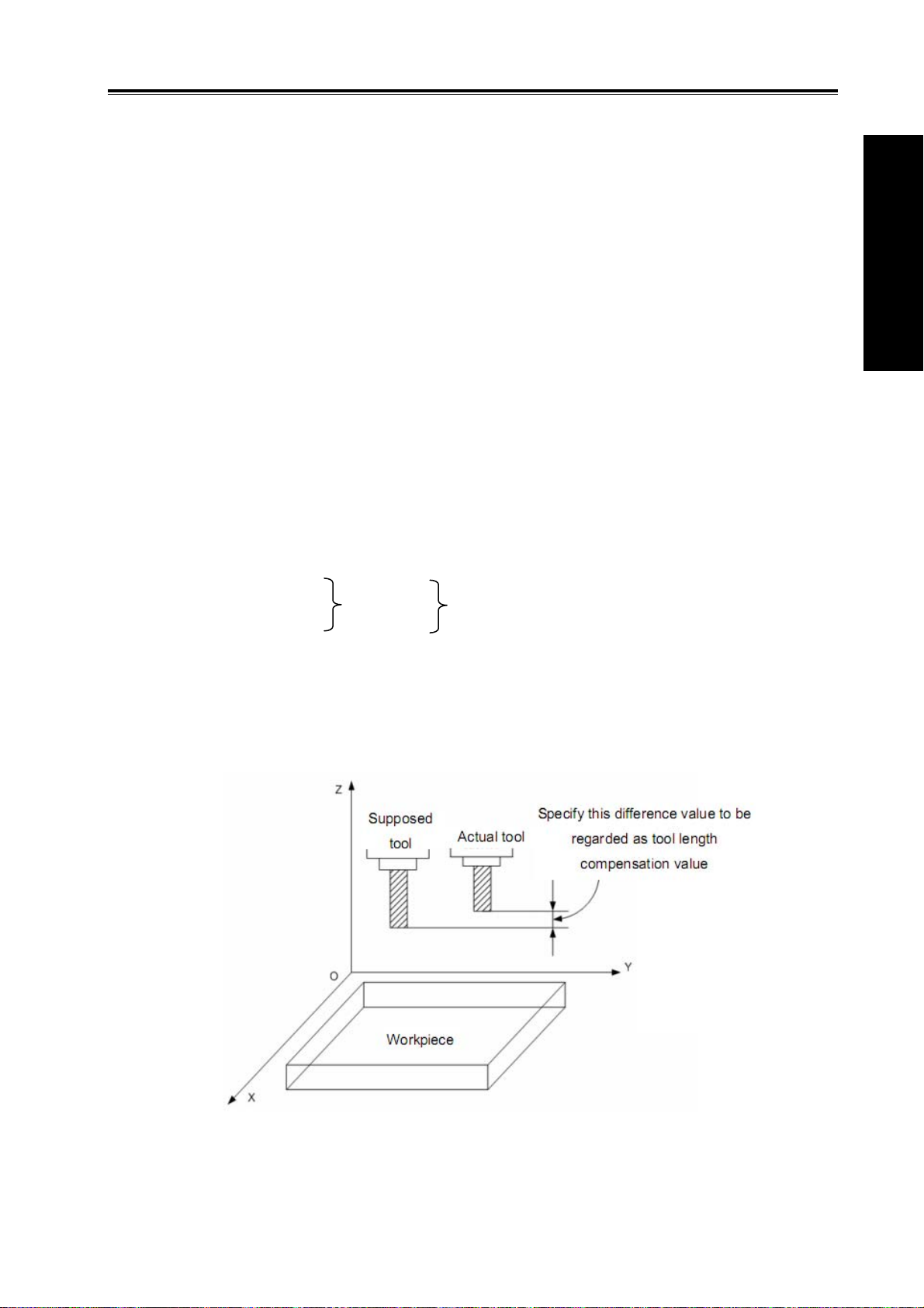
creating the workpiece as P1→P2……P8→P9→P1.
N00 G92 X0 Y0 Z0;
N01 G90 G17 G00 G41 D7 X250.0 Y550.0 ; (The compensation value should be
N02 G01 Y900.0 F150 ;
N03 X450.0 ;
N04 G03 X500.0 Y1150.0 R650.0 ;
N05 G02 X900.0 R-250.0 ;
N06 G03 X950.0 Y900.0 R650.0 ;
N07 G01 X1150.0 ;
N08 Y550.0 ;
N09 X700.0 Y650.0 ;
N10 X250.0 Y550.0 ;
N11 G00 G40 X0 Y0 ;
Chapter 3 G Command
Volume I Programming
pre-set with compensation number)
3.15 Tool Length Compensation (G43, G44, G49)
Function:
Tool length compensation function.
Explanation:
G43 and G44 are modal G codes; they are effective before meeting other G codes in the
same group.
G17
G18
G19
G43
G44
H__
The end point specified by Z axis moves an offset value, as above figure G17
plane is selected. Difference between supposed and actual machined tool length value is pre-set at
the offset storage when the program is applied. Different length tool can be employed by
57

changing tool length compensation value, so, program change is not needed.
r
)
put(
)
Volume I Programming
Different offset directions were specified by G43 and G44, the offset number is specified by H
code.
Offset axis
The offset axes are vertical to the specified planes (G17, G18 and G19)
Tool position offset for two or more axes can be used to specify the offset axis and the offset
axis changed by 2~3 blocks
(Example) X and Y axes compensation
G19 G43 H_ ; …X axis offset
G18 G43 H_ ; …Y axis offset, composed with the previous block, X and Y axes are
compensated.
GSK980MDa Milling CNC System User Manual
Specifying plane Offset axes
G17 Z axis
G18 Y axis
G19 X axis
Offset direction
G43: Positive offset
G44: Negative offset
Compensation axes can be regarded as Z, Y and X. Either absolute or
incremental command, the end point coordinate value specified by Z axis movement command
in program adds the offset specified by H codes in G43 (set in the offset storage), or subtracts the
offset specified by H code in G44, finally, the value calculated is regarded as the end point coordinate.
The following command is indicated for Z axis move omitting: When the offset is positive, G43 is
for an offset in the positive direction; G44 is for an offset in the negative direction.
It reversely moves when the offset is negative value.
Specifying the offset
An offset number is specified by H code and its corresponding offset adds
or subtracts Z axis movement command value in program to get a new Z axis movement
command value. The offset number is H00~H32.
Offset value corresponded with offset number is pre-set in the offset storage by using the panel
of LCD/MDI. Setting range for offset is as follows:
Offset
Offset number 00, i.e. H00 corresponds to the 0 offset. It is disabled to set offset value to H00.
Tool length compensation cancellation
Millimete
-9999.999
input(mm
~
+9999.999
Inch in
-999.9999~+999.9999
inch
G49 or H00 can be specified when the tool length compensation is cancelled. When two or
more axes compensations are cancelled, all of the axes compensation will be cancelled if the G49
is applied. Compensation value of the vertical axis for currently specified plane is cancelled with
58

Chapter 3 G Command
H00. After G49 or H00 is specified, the system immediately cancels the compensation value.
Note 1: In the block that tool length compensation is specified, G02,G03, G04, G92 and G31 cannot be
specified at the same time, otherwise, an alarm will occur.
Note 2:Tool length compensation command can be specified in the block in which canned cycle is specified.
But after the canned cycle is executed, the tool length compensation is disabled and is not modal.
Example:
Normal Modal
G43 H1
G44 G01 X50 Y50 Z50 H2
G90 G00 X100 Y100 Z100
G43 H1
G44 H2
G44 H2
In the same block with G02,G03,G04,G31,G92
G43 H1
G49 G02 X50 R25 H2
G43 H1
G43 H1
In the same block with canned cycle code
G43 H1
G44 G81 X50 R5 Z-70 H2
G90 G00 X100 Y100 Z100
G43 H1
G44 H2
G44 H2
Specified in the canned cycle
G43 H1
G90 G81 X50 R5 Z-70
G49 H2
G49 G0 X75 Y75 Z75 H0
G43 H1
G43 H1
G43 H1
G49 H0
Command Example:
Explanation (H1=10.0mm,H2=20.0mm)
Setting H1, tool length compensation in the positive
direction.
Linear interpolation, setting H2 tool length
compensation in negative direction
Position to X100 Y100 Z100(Z80) with H2
compensation offset.
Setting H1 tool length compensation in the positive
direction.
Alarm occurs.
Setting H1 tool length compensation in the positive
direction.
Setting H2 tool length compensation in the negative
direction. Starts the canned cycle from H2.
Setting H1 tool length compensation in the positive
direction.
Compensation offset with H1; enters into canned
cycle mode.
The tool length compensation (G49,H2) in the canned
cycle is ineffective, and the previous block remains
modal.
Cancel all the axis compensations, and set H0 modal.
Position to X75 Y75 Z75(Z75).
Volume I Programming
Tool length compensation (#1, #2 and #3 hole machining)
59

Volume I Programming
GSK980MDa Milling CNC System User Manual
offset H01 = 4.0
N1 G91 G00 X120.0 Y80.0 ;.....…. ⑴
N2 G43 Z-32.0 H01 ;...........……… ⑵
N3 G01 Z-21.0 ;.........................… ⑶
N4 G04 P2000 ;............................ ... ⑷
N5 G00 Z21.0 ;..........................…. ⑸
N6 X30.0 Y-50.0 ;.......................…. ⑹
N7 G01 Z-41.0 ;.........................….. ⑺
N8 G00 Z41.0 ;..........................….. ⑻
N9 X50.0 Y30.0 ;........................….. ⑼
N10 G01 Z-25.0 ;........................…. ⑽
N11 G04 P2000 ;.........................… ⑾
N12 G00 Z57.0 H00 ;....................... ⑿
N13 X-200.0 Y-60.0 ;...................... ⒀
N14 M30 ;
Z, X or Y axis offsets a value at offset storage positively or negatively from the original end
position according to the above command. Offset axes can be specified with G17, G18 and G19,
offset direction can be specified with G43 and G44. Offset No. corresponding to the offset is specified
by H code.
3.16 Scaling G50, G51
Scaling means programmed figure can be magnified or reduced. The dimension specified by X,
Y, Z can be scaled up or down with the same or different rates of magnification. The magnification rate
can be specified by the program or parameter.
60

Chapter 3 G Command
’
As the above figure, P0 is the scaling center. P1P2P3P4 scales to P1
Format:
Scale up or down along all axes at the same magnification rate
Format Significance of command
G51 X_Y_Z_P_;Scaling start
: Scaling is valid
: (Scaling mode)
X_Y_Z_: Absolute command for center
coordinate value of scaling
P_ :Scaling rate
G50; Scaling cancel
Scale up or down along all axes at a different magnification rate
Format Significance of command
G51 X_Y_Z_I_J_K_;Scaling start
: Scaling is valid
: (Scaling mode)
G50; Scaling cancel
X_Y_Z_:Absolute command for center
coordinate value of scaling
I_J_K_ :Scaling rate for X axis, Y axis, Z
axis respectively
G50,G51 are G code of No.11, it is a modal G code.
The unit of scaling is 0.001.
State parameter SCLX, SXLY, SCLZ(#31.0~#31.2) are used to set whether the scaling function
of each axis is valid.
Explanations:
z Scale up or down along all axes at the same magnification rate
When state parameter XSC (#31.6) is set to 0, if P is specified on the block G51, the scaling is
specified by P, otherwise, the value set by data parameter will be taken as the magnification rate.
z Scale up or down along all axes at a separate scaling.
When state parameter XSC (#31.6) is set to 1, and each axis is scaled up or down at a different
scale, the rate is specified by I, J, K on the block G51. If I, J, K are not specified on the block, the
rate is determined by data parameter SCLVX, SCLVY and SCLVZ(#182~#183).
When a negative scale is specified, mirror image is applied.
z Negative magnification rate
When a negative scale is specified, mirror image is formed (see related explanations of
programmable mirror image)
P2’P3’P4’.
Volume I Programming
61

z Scale of different figure
Volume I Programming
1. Magnification rate of linear scaling
GSK980MDa Milling CNC System User Manual
a/b: Scaling magnification of X axis
a/b:
Y
d
c/d:c/d: Scaling magnification of Y axis
o: Scaling center
Programmed figure
c
Scaled figure
o
X
a
b
2. Scaling of circular interpolation
Even different magnifications are specified to circular interpolation, tool will not trace ellipse.
When magnifications for axes are different, and the circular interpolation is programmed with
radius R, its figure is as follows, (magnification 2 is applied to X-axis and magnification 1 is applied to
Y axis)
Y
Scaled shape
(0,0)
G90 G00 X0.0 Y100.0;
G51 X0.0 Y0.0 Z0.0 I2000 J1000;
G02 X100.0 Y0.0 R100.0 F500;
Above commands are equivalent to the following commands
G90 G00 X0.0 Y100.0 Z0.0;
G02 X200.0 Y0.0 R200.0 F500;
Magnification of radius R is depends on I, or J whichever is larger
When different magnifications are applied to axes, and circular interpolation is specified with I, J,
K, alarm occurs after scaled if a circular is not formed.
3. Tool compensation
The scaling is invalid in tool radius compensation values, tool length compensation values and
tool offset values. Only the figure before scaling are proceeded, namely, scaling is done before the
calculation of tool compensation, see the following figure:
(100,0)
(200,0)
X
62

Chapter 3 G Command
Volume I Programming
Programmed figure
Cutter compensation C values are not scaled
z Invalid scaling
1、In canned cycle, moving scaling of cut-in value Q, Z and retraction value d are invalid.
2、In manual operation, the travel distance can not be increased by using scaling function.
z Commands related to reference position return and coordinate system
In scaling mode, the G codes (G28-G30 etc.) returned to the reference point and G codes (G92,
G54-G59 etc.) of command coordinate system can not be specified. If these G codes must be
specified, specify them after the scaling function is cancelled.
z Position display
Position display indicates the coordinate value after scaling.
Related parameters
0 3 1 XSC *** *** *** SCLZ SCLY SCLX
SCLX、SCLY、SCLZ=1:X、Y、Z Scaling is valid.
0:X、Y、Z Scaling is invalid.
XSC=1: Axes are scaled up or down at different magnification rate. If the rate is a negative value,
mirror image is formed.
0:Axes are scaled up or down at the same magnification rate.
1 8 1 SCLVSAME: Axes are scaled up or down at the same magnification
rate
Scaled
figure
SCLVSAME: If P is not specified, set values with defaulted magnification rate, setting range is
1~99999999.
1 8 2 SCLVX: Magnification rate of X axis
1 8 3 SCLVY: Magnification rate of Y axis
1 8 4 SCLVZ: Magnification rate of Z axis
SCLVX, SCLVY, SCLVZ: Set magnification rate for X, Y, Z axis. Setting range is
-99999999~99999999, which can not be 0.
3.17 Programmable Mirror Image G50.1, G51.1
If the shape of a workpiece is symmetrical on an axis, a part of the workpiece can be
programmed. Then machining program of a whole part can be obtained by using mirror image (or
scaling) and subprogram.
63

Volume I Programming
Format:G51.1 X__ Y__ Z__; Set programmable mirror image
GSK980MDa Milling CNC System User Manual
:;
:;
According to G51.1 X__ Y__ Z__, specified mirror image of
these blocks are generated from specified symmetry axis
:;
G50.1 X__ Y__ Z__; Specify corresponding axis to cancel the mirror image of axes
G50.1,G51.1are G codes of No., which are modal G codes.
Command function:Specify mirror image function for axes.
G51.1 X__ Y__ Z__:Specify mirror image function for axes. (put on the axis as a mirror).
Thereinto, X__ Y__ Z__is an absolute command.
G50.1 X__ Y__ Z__:Cancel mirror image function for axes. If the address of the axis is not
specified, which indicates no mirror image function is cancelled.
Explanations:
1. Some commands are interchanged when a mirror image to the plane is specified.
z G02/G03 of circular commands are interchanged.
z G41/G42 of cutter compensation commands are interchanged.
z CW and CCW(directions of rotation)are interchanged.
2. This function is not effective for 4
th
and 5th axes.
3.In canned cycle, the depth of Z are not proceeded with the mirror image.
Limitations
z In programmable mirror image, G codes related to reference return(G27/G28/G29/G30, etc.)
and those for changing the coordinate system(G52~G59,G92, etc)can not be specified. If any
of these G codes is necessary, specify it only after canceling the programmable mirror image
mode.
z Processing proceeds from program mirror image to scaling and coordinate rotation. The
commands should be specified in order, for cancellation, in the reverse order. G50.1 and G51.1
can not be specified in scaling and rotation mode.
64

Modal display of scaling
Chapter 3 G Command
Volume I Programming
Program
System
display
3.18 Setting Local Coordinate System G52
When a program is created in a workpiece coordinate system, the subprogram of the workpiece
cooedinate system (G54-G59) can be set for easy program. Sub coordinate system is called local
coordinate system.
Machine coordinate system, workpiece coordinate system and local coordinate system
The machine coordinate system is a fixed coordinate system on the machine, it indicates a fixed
position of the machine.
The workpiece coordinate system is a system facilitates workpiece machining, in which the
reference point on the workpiece is taken as the origin point.
Local coordinate system is set on workpiece coordinate system to facilitate the programming of
some machining programs.
Format:G52 IP;…… Set local coordinate system
G52 IP0;……Cancel local coordinate system
IP:Specify the position of the origin point of the local coordinate system in the current
workpiece coordinate system
G52 is G code of the group, which is a non-modal G code.
65

Volume I Programming
GSK980MDa Milling CNC System User Manual
Local coordinate system
IP_
G54:Workpiece coordinate system 1
Reference point
G55 G56
Machine coordinate system origin
G57
G58
G59:Workpiece coordinate system 6
Local coordinate system
IP_
Explanations
z When the local coordinate is set, the following movement specified by absolute mode (G90) is
coordinate value in local coordinate system. The position of the local coordinate system can be
changed by specifying new origin point with G52.
z In order to specify the origin of the machining program and the offset value of the workpiece
origin, replace command G92 by specifying command G52.
z Make the origin of the local coordinate consistent with the zero point of the workpiece coordinate
system to cancel the local coordinate system and specify the value in workpiece coordinate
system.
z When a G52 is specified, local coordinate system is valid before another G52 command is
specified. It is not move when G52 command is being specified.
Example
Set local coordinate system in a single workpiece coordinate system.
N1 G28 X0 Y0 Z0;
N2 G90 G54 G00 X100 Y100;
N3 G92 X0 Y0;
N4 G00 X50 Y50;
N5 G52 X100 Y100;
N6 G00 X0 Y0;
N7 G01 X50 F100;
N8 Y50;
N9 G52 X0 Y0;
N10 G00 X0 Y0;
N11 M30;
The local coordinate system is set by G54 coordinate system in the block N5. It is cancelled in
the block N9, whose cancelled coordinate system is consistent with that set by G92 of block N3.
Set local coordinate system in multiple worikpiece coordinate systems
66

Chapter 3 G Command
N1 G28 X0 Y0 Z0;
N2 G90 G54 G00 X0 Y0;
N3 G52 X50 Y50;
N4 M98 P1234;
N5 G90 G55 G00 X0 Y0;
N6 M98 P1234;
N7 G90 G54 G00 X0 Y0;
O1234 (Subprogram)
N8 G00 X0 Y0;
N9 G01 X50;
N10 Y50 M99;
Multiple local coordinate systems in the workpiece coordinate system
N1 G28 X0 Y0 Z0;
N2 G90 G54 G00 X0 Y0;
N3 M98 P1234;
N4 G52 X100 Y100;
N5 M98 P1234;
N6 G52 X200 Y200;
N7 M98 P1234;
N8 G52 X0 Y0;
(N8 G91 G52 X-200 Y-200;)
O1234 (Subprogram)
N11 G00 X0 Y0;
N12 G01 X50;
N13 Y50;
N14 X0 Y0 M99;
The local coordinate system generated from the N8 block in the brackets is consistent with the
workpiece coordinate G54, which is the same with the result after (N8 block) is cancelled in the local
coordinate system.
Notes
z When the parameter No.016#5 ZC is set to 1, the local coordinate system of the axis is cancelled
in the process of reference return.
G52 a0;(a is the axis return to the reference point)
z The workpiece coordinate system and the machine coordinate system are not changed by
setting the local coordinate system.
z Parameter setting determines whether cancel the local coordinate system after reset. When the
parameter No.016#7 RLC is set to 1, all local coordinate systems of the workpiece coordinate
system are cancelled.
z When the workpiece coordinate system is set by specifying command G92, the local coordinate
system of all workpiece coordinate systems of the specified axis is cancelled. If the coordinate
Volume I Programming
67

values of the axes not all specified, the local coordinate systems of the unspecified axes are not
Volume I Programming
cancelled, that is, keep unchanged.
z Command G52 can not be specified at the same block with the length compensation command,
otherwise, alarm occurs. Cancel the offset of the tool radius compensation temporarily when the
G52 command is being specified.
z After block G52, specify travel command immediately by absolute value mode.
Related parameters
0 1 6 RLC MRC ZCL
RLC = 1:Local coordinate system is cancelled after reset
RLC = 0:Local coordinate system is not cancelled after reset
MRC = 1:Local coordinate system is cancelled after the execution of M02, M30
MRC = 0:Local coordinate system is not cancelled after the execution of M02, M30
ZCL = 1:Local coordinate system is cancelled after returning to the reference point
GSK980MDa Milling CNC System User Manual
ZCL = 0:Local coordinate system is not cancelled after returning to the reference point
3.19 Select Machine Coordinate System G53
A specific point that serves as the reference point is referred to the machine zero point. The
coordinate system with a machine zero point set as its origin is referred to a machine coordinate
system. A machine coordinate system is set by performing manual reference position return after
power on. Once the machine coordinate system is set, it remains unchanged until the power is turned
off.
Format:(G90)G53 IP_;
Explanations: IP_:Tool travel amount is specified by absolute value.
When a position on a machine coordinate system is specified, the tool moves to the position by
rapid traverse. G53, which is used to select a machine coordinate system, is a non-modal G code. It
is valid only in the block that specifies the machine coordinate system. The absolute value specifies X,
Y, Z. When the tool moves to the specific position, for example: tool exchange position, travel
program on the machine coordinate system should be edited by G53.
Restrictions:
z Cancel of the compensation function
When the G53 command is specified, cancel the radius compensation. However, the parameter
NO.22 determines whether the tool length compensation is cancelled or not.
z G53 Specify G53 immediately after power on
Since the machine coordinate system must be set before the G53 command is specified, manual
reference position return or automatic reference position return by the G28 command must be
performed after the power on. Otherwise, P/S alarm occurs: G53 can not be performed before
reference position return.
68

Chapter 3 G Command
z In the same block with other G commands
1. In the same block with group 03 (G90, G91)
G53, G90 and G91 are performed normally, and related modal is updated. The position
command specified by G53 is treated as absolute position.
2. In the same block with tool length compensation and tool radius compensation
G53 is performed normally, and cancel the tool length compensation and tool radius
compensation.
3. G53 and the group 01 in the same block
When it is in the same block with group 01 G command, P/S alarm occurs.
z Processing in the canned cycle
When canned cycle is valid, P/S alarm will occur after G53 is specified: G53 can not be specified
if the canned cycle is valid.
Coordinate display:
After the CNC system is powered on and returned to the reference point, a machine coordinate
system is set immediately, whose coordinate values are set by parameter NO145~149.
Volume I Programming
Example
Initial position -110,-110,-110 40,40,40 -120,-120,-120
G53 X25 Y25 Z25;
G0 X0 Y0 Z0;
G1 X40 Y40 Z40;
Relative coordinate
(X,Y,Z)
35,35,35 185,185,185 25,25,25
-150,-150,-150 0,0,0 -160,-160,-160
-110,-110,-110 40,40, 40 -120,-120,-120
Absolute
coordinate(X,Y,Z)
Machine
coordinate(X,Y,Z)
3.20 Workpiece Coordinate System G54~G59
Format:
G54 X
G55 X
G56 X
G57 X
G58 X
Y Z ; Workpiece coordinate system 1
Y Z ; Workpiece coordinate system 2
Y Z ; Workpiece coordinate system 3
Y Z ; Workpiece coordinate system 4
Y Z ; Workpiece coordinate system 5
G59 X
Y Z ; Workpiece coordinate system 6
69

Function:
Volume I Programming
There are 6 workpiece coordinate systems for machine tool regardless of the G92, any of
coordinate system can be selected by G54~G59.
Explanation:
X: New X axis absolute coordinate in current position;
Y: New Y axis absolute coordinate in current position;
Z: New Z axis absolute coordinate in current position.
These six workpiece coordinates are set by the distances (workpiece zero offset)
from machine zero to each coordinate system origin.
GSK980MDa Milling CNC System User Manual
Examples:
N10 G55 G90 G00 X100.0 Z20.0;
N20 G56 X80.5 Z25.5;
Rapidly positioning to workpiece coordinate system 3 (X=80.5, Z=25.5) from workpiece
coordinate system 2 (X=100.0, Z=20.0). For example, if N20 block is G91, it is incremental
movement. The absolute coordinates automatically become the coordinates in coordinate system
G56.
Z
Z
N20(G91)
(80.5,25.5)
(X2,Z2)
(80.5,25.5)
G56
N10
N20
(G90)
X
70
(100,20)
G55

The absolute position for the figure is coordinate value under the current coordinate system.
Note:
z Workpiece coordinate systems 1~6 is set up as soon as machine zero return is
z Whether the relative position varies with coordinate system depends on status
z When the workpiece coordinate system function is determined, usually, G92 is not
z Workpiece coordinate system can be modified in the program run. The new coordinate
Chapter 3 G Command
executed after power-on. When the system is restarted, the coordinate system is the
one set by parameter No. 13 bit 17.
parameter №005 PPD. when PPD=0, it changes; when PPD=1, it does not change.
needed to set coordinate system. if G92 is used, coordinate system 1~6 will be moved.
Do not confuse with G92 and G54~G59, unless workpiece coordinate systems
G54~G59 are to be moved. When G54~G59 are in the same block with G92, G54~G59
are disabled.
system is effective till the system is restarted.
Volume I Programming
If it performs G92 X100 Y100 commands when the tool is positioned a(t 200,160)in the G54
coordinate system; the offset vector A for workpiece coordinate system 1 is (X’, Y’). And the other
workpiece coordinate systems offset for vector A.
3.21 Coordinate System Rotation G68, G69
The programmed shape can be rotated. By using this function (rotation command), a workpiece
can be rotated with a specific angle. If the pattern of the workpiece comprising some identical shapes,
the time required for programming and the length of the program can be reduced by editing a
subprogram and calling it with the rotation command of the main program. The function is as follows:
Y
Angle of rotation
Center of rotation
X
71

Format: G17
Volume I Programming
G68, G69 are G codes of the group 16, which is a modal G code.
Explanations:
G17 (G18 or G19): Because they only support the rotation on two-dimension plane, select
related plane and perform rotation on it.
α, β: The center of rotation. Absolute coordinate commands of two axes of X, Y and Z axes that
correspond to the specified coordinate plane.
R: The positive value of angular displacement indicates CCW rotation. The state parameter
NO.032 bit7(RIN)determines whether the rotary angle is always an absolute value or specified by a
specific G code (G90/G91). When R is not defined, the value specified by the data parameter NO.187
is taken as the angular displacement value.
The minimum input unit of the angular displacement: 0.001deg(IS-B)
G18 G68 α_ β_ R_; //Start rotation of a coordinate system
G19
...
...
G69; // Cancel rotation of a coordinate system
GSK980MDa Milling CNC System User Manual
//Coordinate system rotation mode (The coordinate system is rotated)
Effective data range of angular displacement: -360.000~360.000deg(IS-B)
X
Angle of rotation R( incrementa l value)
Angle of rotation (absolute value)
(α,β)
Absolute angle
If the default initial absolute angle is 0 degree, the first specified absolute angle is equivalent to
the relative angle specified the same value. If the figure is rotated to the position of 90 degrees, it can
be specified by absolute angle or relative angle. Because the position that rotates to 90 degrees
(absolute) for the first time and where rotates 90 degrees (relative) from 0 degree are the same.
When the figure has been rotated 90 degrees and then 30 degrees to be rotated, rotary angle of 120
degrees should be edited if absolute angle specifying is used, that is, rotate the figure to 120 degrees
from 0 degree. If relative specifying is used, angle of rotation should be edited as 30 degrees, that is,
rotates 30 degrees from 90 degrees to achieve the same effect with the other way.
Center of rotation
Z
72

Chapter 3 G Command
Explanations
¾ Plane selection
Plane selecting code (G17-gG19) can not be specified in the coordinate system rotation mode.
¾ Center of rotation
When α, β are not programmed, the tool position (current position) of block G68 is assumed as
the center of rotation.
¾ Angle of rotation
When angle of rotation (R command) is not specified, the value specified in parameter NO.187 is
assumed as the angle.
¾ Rotation cancellation
The G code (G69) used to cancel coordinate system rotation mode can be specified in a block
where another command is specified.
Limitations:
¾ Commands related to the coordinate system
In coordinate system rotation mode, G codes (G28, G29, G30, etc.) related to reference position
return and those related to coordinate system (G52 to G59,G92) can not be specified. These G
codes should not be specified in coordinate system rotation mode, otherwise, alarm occurs.
¾ Radius compensation C mode
In radius compensation C mode, coordinate rotation mode can not set to be valid. First cancel
the radius compensation if it is necessary to specify.
¾ Rotation center command
Rotation center must be specified by absolute value in coordinate system rotation mode. The
rotation center of the relative command is assumed as the absolute command.
¾ Increment command
The first move command after canceling the coordinate rotation command must be specified by
absolute value. If it is specified by increment, the movement will not perform correctly.
Related parameter
0 3 2 RIN *** *** *** *** *** *** ***
Volume I Programming
RIN = 1:The angle of coordinate system rotation is specified by command G90 or G91
RIN = 0:The angle of coordinate system rotation is always an absolute command
1 8 7
Setting range:-360000 ~ 360000(unit:0.001deg)(IS-B)
Example:
N1 G90 G69 G54 G49 G40 G17 X-50 Y-50 Z30
N2 G68 X70 Y30 R45 (N2 G68 R45)
N3 G90 G01 X0 Y0 F800
N4 G91 X100
N5 G02 Y100 R100
N6 G03 X-100 I-50 J-50
N7 G01 Y-100
N8 G90 G69 X-50 Y-50
N9 M30
When the angle of rotation is not specified, the angle in coordinate
system rotation
73

Volume I Programming
GSK980MDa Milling CNC System User Manual
Tool path when the command is executed in the brackets N2
Originally programmed tool path
(70,30)
45°
( 0 , 0 )
Tool path after rotation
( -50, -5 0)
Center of rotation
Coordinate rotation and cutter compensation C
Cutter compensation C can be specified in G68 and G69 mode. The rotation plane must
consistent with the plane of tool compensation.
N1 G90 G69 G54 G17 G00 X0 Y0
N2 G90 G68 X10 Y10 R-30
N3 G42 G01 X10 Y10 F800 D1
N4 G91 X20
N5 G03 Y10 R10 J5
N6 G01 X-20
N7 Y-10
N8 G90 G69 G40 X0 Y0
Programmed shape before coordinate system rotation
30°
Tool path
(0,0)
Programmed shape after coordinate system rotation
Scaling and coordinate system rotation
If a coordinate system rotation command is executed in the scaling mode, the rotation center will
also be scaled, but not the rotation angle. When a move command is issued, the scaling is executed
first and then the coordinate are rotated. The command G68 can not be issued in scaling mode (G51)
and cutter compensation C mode. The coordinate system rotation command should always be
specified prior to setting the cutter compensation C mode.
¾ When the system is not in cutter compensation C mode, specify the command in the following
order:
G51; //Scaling mode start
74

Chapter 3 G Command
G68; //Coordinate system rotation mode start
;
G69; // Coordinate system rotation mode cancel
G50; // Scaling mode cancel
¾ When the system is in cutter compensation C mode, specify the command in the following order:
(Cutter compensation C cancel (G40))
G51; // Scaling mode start
G68; // Coordinate system rotation mode start
;
Volume I Programming
G41; // Cutter compensation C mode start
¾ Scaling and coordinate system rotation
N1 G90 G69 G17 G00 X0 Y0
N2 G51 X300 Y150 P500
N3 G68 X200 Y100 R45
N4 G91 G01 X400 Y100 F800
Y
When scaling and coordinate
system rotation are applied
200
100
N5 Y100
N6 X-200
N7 Y-100
N8 X200
When only coordinate system rotation is applied
When only scaling is applied
Cutting progam
X
0
100 200 300 400
Repetitive commands for coordinate system rotation
It is possible to store a program as a subprogram and call subprogram several times by changing
the angle.
The program when RIN (parameter NO.032 bit7) is set to 1. The specified angular displacement
is treated as an absolute or incremental value depending on the specified G code (G90 or G91).
Main program
G92 G69 G17 X0 Y0;
G01 F200 H01;
M98 P2100;
M98 P072200;
G90 G00 X0 Y0;
M30;
O2200
G91 G68 X0 Y0 R45;
G90 M98 P2100;
M99;
O2100
G90 G42 G01 X0 Y-10;
X4.142;
X7.071 Y-7.071
G40;
75

Volume I Programming
GSK980MDa Milling CNC System User Manual
Programmed path
(0,0)
When offset is applied
(0,-10)
subprogram
Note: Because the radius compensation setting and canceling of the above program are done in the
subprogram, the whole workpiece will be over cut if B-type tool starting and retraction of radius
compensation C mode is used. In order to compensate the whole rotated workpiece figure with radius
compensation function when the above program is in execution, please set state parameter NO.002 bit6
SUP to 0, otherwise, above mentioned effects will not be achieved.
3.22 Compound Cycle Command
3.22.1 Brief for Canned Cycle
Generally, the canned cycle is a machining movement completion from one block with G function
to the completion of multi-block specified. Canned cycles make it easier for the programmer to create
programs. With a canned cycle, a frequently used machining operation can be specified in a single
block with a G function; without canned cycles, multiple blocks are needed, and canned cycles can
shorten the program to save memory.
3.22.1.1 Canned cycle list
Table 3-21 Canned cycle
G codes Drilling
Operation at the
bottom of a hole
Retraction Application
G73 Intermittent feed ── Rapid feed
High-speed peck drilling
cycle
G74 Feed Dwell, spindle CCW Feed Left-hand tapping cycle
G80 ── ── ── Canned cycle cancellation
G81 Feed ── Rapid feed Drilling, point drilling
G82 Feed Dwell Rapid feed
Drilling, boring, counter
boring
G83 Intermittent feed ── Rapid feed Peck drilling cycle
G84 Feed Dwell, spindle CW Feed Tapping
G85 Feed ── Feed Boring
G86 Feed Spindle stop Rapid feed Boring
G88 Feed Dwell, spindle stop manual Boring
G89 Feed Dwell Feed Boring
76

Chapter 3 G Command
G110 Intermittent feed
G111 Intermittent feed
G112
G113
G114
G115
Feed
Feed Full-circle fine milling Rapid feed Full-circle internal fine
Feed Full-circle fine milling Rapid feed External round fine milling
Feed Full-circle fine milling Rapid feed External round fine milling
Full-circle helical rough
milling
Full-circle helical rough
milling
Full-circle fine milling
G134 Intermittent feed Rectangle rough milling
G135 Intermittent feed Rectangle rough milling
G136
G137
G138
G139
Feed
Rectangle fine milling
Feed Rectangle fine milling Rapid feed Rectangle groove internal
Feed Rectangle fine milling Rapid feed Rectangle groove external
Feed Rectangle fine milling Rapid feed Rectangle groove external
Rapid feed
Rapid feed
Round groove internal
rough milling CCW
Round groove internal
rough milling CW
Rapid feed Full-circle internal fine
milling CCW
milling CW
CCW
CW
Rapid feed Rectangle groove internal
rough milling CCW
Rapid feed Rectangle groove internal
rough milling CW
Rapid feed Rectangle groove internal
fine milling CCW
fine milling CW
fine milling CCW
fine milling CW
Volume I Programming
3.22.1.2 Canned circle explanations
Generally, a canned cycle consists of a sequence of the following operations, see the right
figure.
Operation 1… Positioning of axis X
and Y
Operation 2…Rapid traverse to point
Operation 1
Start and end points
R plane
Operation 3…Hole machining;
Operation 2
Operation 7
Operation 4…Operation at the
bottom of hole;
Operation 5…Retraction to point R
plane
Operation 6…Rapid traverse to the
Point R
Operation 3
Operation 6
Rapid traverse feedrate
Cutting feed
initial Point
Operation 4
3.22.1.3 G90/G91
The data mode corresponded with G90 and G91 are different. The point R plane and the
absolute position machined at the bottom of the hole are specified by R and Z values, when the
command is G 90. The specified R value is the distance relative to the initial plane, and the Z value is
the distance relative to the R point plane when the command is G91. See the following figure.
77

GSK980MDa Milling CNC System User Manual
Volume I Programming
3.22.1.4 Returning point level G98/G99
Tool can be returned to the initial plane or point R plane according to G98 and G99 during
returning. See the following figure Fig. 3-47.
Normally, the initial hole machining is used by G99, the last machining is used with G98. The
initial level will not be changed when the hole machining is done by G99.
G90 (Absolute command )
In itia l le ve l
Point R plane
Point Z(at the
bottom of hole)
R
Z
Absolute
G91 (Increm ental command)
Point R
Point Z
Fig. 3-46 Absolute and incremental commands for canned cycle
R
Z
Relative
G98 (return to initial level )
Initial level
G99 (return to point R level)
Initial level
Point R
Fig.3-47 Levels for initial and point R
Note :The initial point level is an absolute position for hole machining axis direction which is indicated from
the canned cycle cancellation to start.
3.22.1.5 Canned cycle cancellation
There are two ways for canned cycle cancel are listed below:
1. Canceling the canned cycle with the G80
78

Chapter 3 G Command
2. The canned cycle is cancelled by the G00, G01, G02 and G03 command in group 01.
(1) When the canned cycle is cancelled by the command G80, if the G00, G01, G02 and G03 of
the 01 group are not specified, then the reserved modal command (G00 or G01) performs motion
before using canned cycle.
For example:
N0010 G01 X0 Y0 Z0 F800; (The modal command is G01 before entering the canned cycle)
N0020 G81 X10 Y10 R5 Z-50; (Entering canned cycle)
N0030 G80 X100 Y100 Z100; (The modal G01 command reserved before canned cycle
performs cutting feed )
If the G01 is not specified in the abovementioned program N0010, but G00, the G00 performs
rapid positioning for N0030.
When both command G80 and commands G00, G01, G02 and G03 are specified in block,
actions are performed by the latter, G00, G01, G02 and G03.
For example:
N0010 G01 X0 Y0 Z0 F800; (The modal command is G01 before entering the canned cycle)
N0020 G81 X10 Y10 R5 Z-50; (Entering canned cycle)
N0030 G00 G80 X100 Y100 Z100; (The G00 performs positioning at the rapid rate, and the
modal command G00 is saved)
Note: The cutting feedrate by F command is still held on even if the canned cycle is cancelled.
Volume I Programming
3.22.1.6 General command format for canned cycle
Once the hole machining data is specified in the canned cycle, it is held until the canned cycle is
cancelled. So the hole machining data should be outright specified at the beginning of the canned
cycle, only the modified data is specified in the following canned cycle.
The general command format of canned cycle: G_ X_ Y_ R_ Z_ Q_ P_ F_ L;
All commands for canned cycle are listed in above-mentioned format. But it is not needed to
specify the above-mentioned format in each canned cycle. For example, the canned cycle can be
performed as long as the G command (hole machining) and any of X, Y, Z and R are specified;
additionally, Q or P is not available in some canned cycle G command (hole machining), the
command is disabled even if these data are specified, they are regarded as modal data memories
only.
Table 3-22 Command explanations for canned cycle
Specifying
content
Hole
machining
Hole position
data
Hole
machining
data
Address Explanation for command address
G Refer to the canned cycle list.
X,Y
R
Z
Specifying the hole position with the absolute and incremental value,
control is same with G00 position. Unit: mm;
See the Fig.3-46, the distance from initial point level to point R plane is
specified by using the incremental value, or specifying the coordinate
value of the point R by absolute value. Unit: mm;
Hole depth. the distance from R point to the bottom of a hole is specified
by using the incremental value or specifying the coordinate value of the
hole bottom by absolute value. Unit: mm;
79

GSK980MDa Milling CNC System User Manual
Volume I Programming
A part of command of canned cycle such as G110, G111, G112, G113, G114, G115, G134,
G135, G136, G137, G138 and G139 are explained in the following chapters or sections.
3.22.2 Description for canned cycle
3.22.2.1 High-speed Peck Drilling Cycle G73
Format: G98/G99 G73 X_ Y_ R_ Z_ Q_ F_ L_;
Function: This kind of cycle performs high-speed peck drilling, it performs intermittent cutting
Explanation: Refer to the command explanation of canned cycle in Table 3-22.
Cycle process:
(1) Positioning to XY plane level at the rapid traverse;
(2) Down to the point R plane at the rapid traverse rate;
(3) Cutting feed for Q distance;
(4) Retract d distance in rapid traverse;
(5) Cutting feed for (Q+d) distance
(6) Machine to the Z axis hole bottom by cycling the (4) and (5);
(7) Return to the start point level or point R plane according to G98 or G99 at the rapid traverse.
Command Path:
Q
P
L
Specifying each cut-in in G73 and G83 or translational value in G76 and
G87. Unit: mm;
Specifying the dwell at the bottom of a hole. Relation of time and the
numerical specified are same with G04. Unit: ms;
Machining cycle for L holes is performed from start (start position of block)
to XY coordinate position.
F The cutting feedrate is specified, tooth pitch is indicated in G74 and G84.
feed to the bottom of a hole, and eliminating the chips from the hole simultaneously.
G73( G98) R eturn to the
initial plane at the rapid traverse
Initial le vel
Point R
q
q
q q
d
d
Point Z
G73( G99) Return to the point
R plane at the rapid traverse
Point R
q
q
d
d
Point Z
80

Chapter 3 G Command
Related Explanation:
(1) This kind of cycle is peck drilling for Q value intermittent feeding along the Z-axis direction.
The Q value should be positive, the sign is ineffective even if the negative value is specified. If the Q
value is not specified, then it defaults 0.1mm. If a depth to be cut is less than the Q value, then cut to
the bottom of the hole without tool retraction at the rapid traverse for the first time.
(2) To remove chips from the hole easily, a small value can be set for retraction. This allows
drilling to be performed efficiently. The tool is retracted in rapid feed, the retraction amount d is set by
parameter No.51, the default is 1000, unit: 0.001mm.
(3) The command P is disabled, but its value is reserved as canned cycle modal value.
3.22.2.2 Left-handed Tapping Cycle G74
Format: G98/G99 G74 X_ Y_ R_ Z_ P_ F_ L
Function: This cycle performs left-handed tapping. In the left-handed tapping cycle, the
spindle rotates clockwise for tapping till the bottom of the hole has been reached, then
retracts by counter-clockwise after dwell.
Explanation: For canned cycle explanation, see the Table 3-22.
Thereinto, the F is indicated for tooth pitch. The value range are indicated as 0.001~500.00mm
(metric), 0.06~25400 teeth/inch (inch)
Cycle process:
(1) Positioning to XY plane level at the rapid traverse;
(2) Down to the point R plane at the rapid traverse;
(3) Tapping to the bottom of a hole;
(4) The spindle stops;
(5) Pause for time P if dwell is specified;
(6) The spindle rotates CCW, and then retracts to point R plane;
(7) The spindle is stopped; pause for time P if dwell is specified;
(8) Spindle rotates CW;
(9) Return to the initial plane if it is G98.
Command Path:
G74(G98)(Mode for
returning to initial plane )
G74(G99)(Mode for
returning to R point plane)
Volume I Programming
Initial level
Point R level
Point R
Spindle cw
P
Point Z
Spindle ccw
P
Point R
Spindle cw
P
Point Z
Spindle ccw
P
81

Related Explanation:
Volume I Programming
(1) Tapping to the bottom of a hole it will not be returned immediately even if the P is omitted or
regarded as 0 in this cycle, it will be returned after a dwell time (2s), and this time is set by
system.
(2) The F is tapping modal value, the last tapping F value is taken when it is omitted, or alarm will
be generated if it does not exist.
(3) The metric or inch of the F value is determined by G20 (metric) or G21 (inch).
(4) The command Q is disabled in this cycle, but its value will be reserved as canned cycle modal
value.
3.22.2.3 Tapping Cycle G84
Format: G98/G99 G84 X_ Y_ R_ Z_ P_ F_ L_ ;
Function: This cycle is used to machine a thread. The tapping is performed by spindle rotating
Explanation: For command explanation of canned cycle, see the Table 3-22.
There into, the F is tooth-pitch. The value range is 0.001~500.00mm (metric), 0.06~25400
tooth/inch (inch).
Cycle Process:
(1) Positioning to the XY plane level at the rapid traverse;
(2) Down to the point R plane at the rapid traverse;
(3) Tapping to the bottom of a hole;
(4) Spindle stops;
(5) For dwell time P if it is commanded
(6) Spindle returns to the point R plane in reverse direction;
(7) Spindle stops; for dwell time P if the P is commanded;
(8) The spindle is rotated in the positive direction;
(9) Returning to the initial point level if it is G98.
Command Path:
GSK980MDa Milling CNC System User Manual
positively, when the bottom of a hole has been reached, the spindle is retracted in
the reverse direction.
G84(G98)(Mode for
returning to initial plane )
G84(G99)(Mode for
returning to R point plane)
Initial level
Point R
Spindle ccw
P
Spindle cw
P
Point Z
Point R
Spindle ccw
P
Point Z
Related Explanation:
Please refer to the related explanation for G74 (Counter tapping cycle)
82
Point R level
Spindle cw
P

Chapter 3 G Command
3.22.2.4 Drilling Cycle, Spot Drilling Cycle G81
Format: G98/G99 G81 X- Y_ R_ Z_ F_ L_ ;
Function: This cycle is used for normal drilling. Cutting feed is performed to the bottom of the
hole, the tool is then retracted from the bottom of the hole in rapid traverse.
Explanation: For the command explanation of canned cycle, see the Table 3-22.
Cycle Process:
(1) Positioning to the XY plane level position at the rapid traverse;
(2) Down to the point R plane at the rapid traverse;
(3) Cutting feed to the bottom of the hole;
(4) Returning to the initial point or point R plane at rapid traverse according to the G98 or G99;
Command Path:
G81(G98) Return to the
initial plane at the rapid traverse
Initial level
G81(G99)( Return to the R
point plane at the rapid traverse)
Volume I Programming
Point R
Point Z
Point R
Point Z
Point R level
Related Explanation:
The command Q or P is disabled in this cycle, but its value will be saved as canned cycle modal
value.
3.22.2.5 Drilling Cycle, Counter Boring Cycle G82
Format:G98/G99 G82 X_ Y_ R_ Z_ P_ F_ L_ ;
Function: Cutting feed is performed to the bottom of the hole. Hole depth precision is added
when the dwell is performed, and then the tool is retracted from the bottom of the hole
at rapid traverse.
Explanation: For the command explanation of these canned cycles, see the Table 3-22.
Cycle process:
(1) Positioning to the XY plane level at the rapid traverse;
(2) Down to the point R plane at the rapid traverse;
(3) Cutting feed to the bottom of a hole
(4) Dwell for P time if it is commanded.
(5) Returning to the initial point or point R plane according to G98 or G99 at the rapid traverse;
83
 Loading...