

Page 1

In this user manual we have tried to describe the matters
concerning the operation of this CNC system to the greatest extent.
However, it is impossible to give particular descriptions for all
unnecessary or unallowable operations due to length limitation and
products application conditions; Therefore, the items not presented
herein should be regarded as ―impossible‖ or ―unallowable‖.
Copyright is reserved to GSK CNC Equipment Co., Ltd. It
is illegal for any organization or individual to publish or reprint this
manual. GSK CNC Equipment Co., Ltd. reserves the right to ascertain
their legal liability.
I
Page 2

GSK96 Multi-function Position Control System User Manual
II
Preface
Dear Users,
We are honored by your purchase of the products made by GSK CNC
Equipment Co., Ltd.
The manual describes the programming, operation, installation and
connection of this GSK96 multi-function position control system in detail.
To ensure safe and effective running, please read this manual carefully
before installation and operation.
Notes before operation:
Connect the emergency stop button of the system firmly and correctly. As the
system uses the normal-closed contact, an emergency stop alarm will occur
upon power on if the buttion is poorly connected or connected as the
normal-open contact, and the system cannot work properly (it does not belong to
system fault).
Set the program reference point of the system according to the actual mounting
position of the tool. Using program reference point function before setting the
point may casue unexpected accidents.
Warning
Accident may occur by improper connection and operation!This
system can only be operated by authorized and qualified personnel.
Special caution:
The power supply fixed on/in the cabinet is exclusively used for the
CNC system made by GSK.
It can't be applied to other purposes, or else it may cause serious
danger!
Page 3

ANNOUNCEMENT!
This manual describes various possibilities as much as possible. However,
operations allowable or unallowable cannot be explained one by one due to
so many possibilities that may involve with, so the contents not specially
stated in this manual shall be regarded as unallowable.
WARNING!
Please read this manual and a manual from machine tool builder carefully
before installation, programming and operation, and strictly observe the
requirements. Otherwise, products and machine may be damaged,
workpiece be scrapped or the user be injured.
CAUTION!
Functions, technical indexes (such as precision and speed) described in
this user manual are only for this system. Actual function configuration and
technical performance of a machine tool with this CNC system are
determined by machine tool builder’s design, so functions and technical
indexes are subject to the user manual from machine tool builder.
Though this system adopts standard operation panel, the functions of the
keys on the panel are defined by PLC program (ladder diagram). It should be
noted that the keys functions described herein are for the standard PLC
program (ladder diagram).
For functions and effects of keys on control panel, please refer to the user
manual from machine tool builder.
This manual is subject to change without further notice.
III
Page 4

GSK96 Multi-function Position Control System User Manual
IV
Suggestions for Safety
The user must carefully read the suggestions for the system before installing and operating the
system.
The user must follow the suggestions of the system to ensure that the person is not hurt and the
equipments are not damaged.
The user must follow the related suggestions for safety described in the user manual, and must not
operate it until the manual is read completely.
The user must follow the suggestions of safety described in the user manual from the machine
manufacture.
The user can operate the machine or compile the program to control the machine after completely
reading the manual and the one from the machine manufacturer.
I. Graphic symbol
Caution Operation against the instructions may cause the operator serious
injuries.
Alarm Wrong operation may injure the operator and damage the system.
Warning Improper operation may result in damage to the machine, as well its
products.
Important information
Page 5

V
II. Notes
1) Check before acceptance
Warning ● The damaged or defect product must not be used.
2) Delivery and storage
Warning ●Moistureproof measures are needed while the system is delivered and stored.
Never climb the packing box, stand on it, or place heavy items on it. Do not put
over five packing boxes in piles. Take particular care of the front panel and the
display of the system.
3) Installation
Warning ●Protect the system from sunlight and raindrops. The shell of the system is not
Contents
waterproof.
Warning ●Prevent dust, corrosive air, liquid, conductors and inflammable substances
from entering the system.
●Keep the system away from inflammable and explosive substances. Avoid
places where there is powerful electromagnetic interference.
●Install the system firmly without vibration.
4) Wiring
Caution ●Only qualified persons can connect the system or check the connection. The
connecting wires cannot be damaged. Do not press or open the cover of the
system with power on.
Caution ●The voltage and the polarity of connecting plugs must accord with the user
manual.
●Wet hands are dangerous to grasp the plug or the switch.
Warning ●The connection must be proper and firm.
●The system must be earthed.
Page 6

GSK96 Multi-function Position Control System User Manual
VI
5) Debugging
Warning ●Make sure that the parameters of the system is correct before the system runs.
●No parameter is beyond the setting limit in the manual.
6) Operation
Caution ●Only qualified operators can operate the system.
●Ensure the switch is OFF before connecting the power supply.
Warning ●The operator cannot leave the system to work alone.
●Do not switch on the system until making sure the connection is correct.
●The emergency stop button is able to disconnect all power supplies when the
system breaks down. Do not switch on/off the system frequently
Warning ●Prevent the system from the environmental interference.
7) Troubleshooting
Caution ●Unqualified persons cannot repair the system.
Warning ●After alarms, do not restart the system until the breakdown is fixed.
Page 7

VII
III. Safety suggestions for programming
1) Setting a coordinate system
Incorrect coordinate system may cause the machine not to work as expected even if the
program is correct, which may injure the operator, and damage the machine as well as its
tool and workpiece.
2) Rapid traverse (positioning)
When G00 rapid traverse performs the positioning (nonlinear motion to position between
its starting point and end point), make sure that the path for the tool is safe before
programming. The positioning is to perform the rapid traverse, and when the tool and the
workpiece are interfered, the tool, the machine and the workpiece may be damaged, and
even the operator injured.
Contents
3) Applicability of user manual
The manual introduces in detail all functions of the system, including optional functions
and max. controllable ranges, which are subject to change with the machine. Therefore,
some functions discribled in this manual will not work out for other specified manchines.If
there is any doubt, please read the instruction for the machine.
4) Functions of CNC system and machine
CNC machines depend on CNC systems, but also power voltage cabinets, servo systems,
CNC and the operator panels. It is hard to explain all the integrated functions,
programming and operation. Do not use integrated instructions not included in the manual
until they have been tested successfully.
Page 8

GSK96 Multi-function Position Control System User Manual
VIII
IV. Notes and Safety Suggestions for Operating Machine
1) Before parts processing
Test the machine without workpiece or tools. Make sure that the machine runs well before it
starts to work.
2) Before operating the machine
Check the input data of the system carefully before operating the machine. Incorrect input
data may cause the machine to work improperly, and damage the workpiece and the tool,
as well as injure the operator.
3) Adaptations between appointed federate and machine operations
Make sure that the input feedrate of the system is suitable for the expected operation.
Feedrate has a maximum for each machine, and the amount of the feed rate is subject to
change with operation. Choose the maximum according to the instructions of the machine.
Improper feedrate leads the machine to work wrongly, and damage the workpiece and the
tool, as well as injure the operator.
4) Compensation function
When offset is needed, check the direction and the amount of the compensation.
Improper compensation causes the machine to work wrongly, and damage the workpiece
and the tool, as well as injure the operator.
5) Manual operation
If the machine is to run in JOG working mode, check the current position of the tool and the
workpiece, and correctly specify the moving axis, moving direction and the feedrate. MPG
(Hand wheel) control with great override, such as 100%, rotate MPG (used to call electric
hand wheel), then the tools and workbench will move fast, which may lead the stop of the
MPG. However, the tools and workbench will not stop immediately. The high override of
MPG movement may damage the machine and its tool, even injure the operator.
6) MPG returns to the reference point
If the tool is return to the reference point, make sure that the machine has been equipped
with the device to detect the reference point; otherwise, the tool cannot reach the reference
Page 9

Contents
IX
point, which may damage the machine and its tool, and even injure the operator.
Safety Responsibility
Manufacturer’s Responsibility
——Be responsible for the danger which should be eliminated and/or controlled on
design and configuration of the provided CNC systems and accessories.
——Be responsible for the safety of the provided CNC systems and accessories.
——Be responsible for the provided information and advice for the users.
User’s Responsibility
——Be trained with the safety operation of CNC system and familiar with the safety
operation procedures.
——Be responsible for the dangers caused by adding, changing or altering on original
CNC systems and the accessories.
——Be responsible for the failure to observe the provisions for operation, adjustment,
maintenance, installation and storage in the manual.
This manual is reserved by end user.
We are full of heartfelt gratitude for your support by using GSK’s
products.
Page 10

GSK96 Multi-function Position Control System User Manual
X
Operation
Introduces operation methods, technical specifications and
parameter settings of GSK96 multi-function position control
system.
Programming
Introduces command codes and program format of GSK96
multi-function position control system.
Appendix
Introduces supplementary information to installation and
connection of GSK96 multi-function position control system.
Connection
Introduces installation and connection methods of GSK96
multi-function position control system.
Page 11

Contents
XI
CONTENTS
Suggestions for Safety ·················································································· IV
OPERATION ·································································································· 1
Chapter 1 Overview ··························································································· 1
Chapter 2 Technical Specifications ········································································ 2
2.1 GSK96 Technical specifications ···················································································· 2
Chapter 3 Operation Panel ··················································································· 3
3.1 LCD Display ············································································································· 3
3.2 LED Status Indicator ·································································································· 3
3.3 Keyboard ················································································································ 3
3.3.1 Character keys ································································································ 3
3.3.2 Working mode selection key ············································································· 3
3.3.3 Function keys ································································································· 4
3.3.4 Cycle start and cycle pause (feed hold) key ························································· 5
3.3.5 Manual axis control key ···················································································· 5
3.3.6 Manual auxiliary function key ············································································ 5
3.3.7 Edit keys ········································································································ 6
3.3.8 Reset Key ······································································································· 7
Chapter 4 System Operation ················································································· 8
4.1 System ON/OFF, Initial State, Modal, and Safe Protection ·················································· 8
4.1.1 Power on ·········································································································· 8
4.1.2 Power off ·········································································································· 8
4.1.3 System, program initial and modal ······································································· 9
4.1.3.1 the initial state and modal of the system ······························································ 9
4.1.3.2 Initial mode and modal of program ····································································· 9
4.1.4 Safe protection ································································································ 10
4.1.4.1 Hardware limit protection ·············································································· 10
4.1.4.2 Software limit safe protection ········································································· 11
4.1.4.3 Emergency stop alarm (emergently stopping the system) ···································· 12
4.1.4.4 Drive unit alarm ·························································································· 14
4.1.4.5 Other alarms ······························································································ 14
4.1.4.6 Switching off power supply ············································································ 14
4.1.4.7 Reset operation ·························································································· 14
4.2 CNC Working Mode Selection ····················································································· 15
4.3 EDIT Working Mode·································································································· 16
4.3.1 Part program catalog search ············································································· 17
4.3.2 Selecting, creating, deleting, renaming and copying a part program ····················· 17
4.3.2.1 Selecting and creating a part program ····························································· 17
4.3.2.2 Delete a part program ·················································································· 18
4.3.2.3 Deleting all part programs ············································································· 19
4.3.2.4 Renaming a part program ············································································· 19
4.3.2.5 Copying a part program ················································································ 19
4.3.3 Part program communication ·········································································· 20
4.3.3.1 Sending part programs (CNC→USB) ······························································ 20
4.3.3.2 Receiving part programs(USB→CNC) ····························································· 20
4.3.3.3 TXT part program standard format in U disc ····················································· 21
4.3.4 Part program content input and edit ································································· 22
4.3.4.1 Inputting program content ············································································· 24
4.3.4.2 Inserting program line ·················································································· 24
4.3.4.3 Deleting a block ·························································································· 25
4.3.4.4 Inserting a character in a block ······································································ 25
4.3.4.5 Deleting a character in a block ······································································· 25
4.3.4.6 Modifying a block content ············································································· 25
4.3.4.7 Program stored space ·················································································· 26
4.3.4.8 No. 253 program operation ··········································································· 26
4.3.4.9 No. 254 program operation ··········································································· 26
4.3.5 hp1 function ·································································································· 27
Page 12

GSK96 Multi-function Position Control System User Manual
XII
4.3.5.1 Part program command help ········································································ 27
4.3.5.2 Inserting macro string ················································································· 27
4.3.5.3 Line number sort ························································································ 28
4.3.5.4 Replacing character string············································································ 28
4.3.5.5 Cursor position ·························································································· 28
4.3.5.6 MPG controlling cursor moving ····································································· 28
4.3.6 Part program compiling ·················································································· 29
4.3.6.1 hp2 compiling command ·············································································· 29
4.3.6.2 Program compiling result analysis ·································································· 29
4.3.6.3 Program compound check prompt ································································· 30
4.4 JOG Working Mode ······························································································· 30
4.4.1 Coordinate axis movement ·············································································· 32
4.4.1.1 JOG movement ························································································· 32
4.4.1.2 Step movement ························································································· 33
4.4.1.3 MPG control ······························································································ 33
4.4.1.4 Rapid traverse speed selection ····································································· 34
4.4.1.5 Low speed feed speed selection ···································································· 35
4.4.1.6 Inputting field moving, setting feedrate ···························································· 36
4.4.1.7 Drive unit enabling control ············································································ 38
4.4.1.8 Coordinate axis motion alarm prompt ····························································· 38
4.4.2 Creating coordinate system ············································································ 38
4.4.2.1 Creating machine coordinate system_machine zero return(machine reference point
return) ················································································································· 38
4.4.2.2 Creating machine coordinate system_without machine zero(no machine reference point)
·························································································································· 40
4.4.2.3 Setting workpiece coordinate system ······························································ 40
4.4.2.4 Setting program reference point ···································································· 42
4.4.2.5 Program reference point return ····································································· 42
4.4.2.6 Recovering the workpiece coordinate system and program reference point ············ 42
4.4.3 Spindle control function ················································································· 43
4.4.3.1 Spindle starting/stopping control ···································································· 43
4.4.3.2 Spindle S command _gear shifting control ······················································· 44
4.4.3.3 Spindle S_ speed control ············································································· 45
4.4.3.4 Servo spindle working state setting ································································ 47
4.4.4 Cooling control ······························································································ 48
4.4.5 Manual tool change control ············································································· 49
4.4.6 Manual tool setting operation ·········································································· 50
4.4.7 Hydraulic chuck control function ····································································· 53
4.4.8 Hydraulic tailstock control function ·································································· 55
4.4.9 Other option functions ···················································································· 57
4.4.9.1 Three-color indicator control ········································································· 57
4.4.9.2 Lubricating control ······················································································ 57
4.4.9.3 Machine electricity delay power-on control ······················································· 58
4.4.9.4 External MPG operation ·············································································· 58
4.4.9.5 Safety door check function ··········································································· 59
4.4.9.6 Pressure low alarm check function ································································· 59
4.4.10 Searching run message in JOG working mode ················································· 59
4.4.11 Appendix: ···································································································· 59
4.4.11.1 MDI input controlling M command table MDI ··················································· 59
4.4.12 Spindle turn function ···················································································· 60
4.5 AUTO Working Mode ····························································································· 61
4.5.1 System working mode in AUTO working mode··················································· 62
4.5.2 Function key operation in AUTO working mode ················································· 62
4.5.2.1 SINGLE execution and CONTINUOUS execution switch ···································· 62
4.5.2.2 Dry run and machining run switch ·································································· 63
4.5.2.3 Running a part program from the first block ························································ 63
4.5.2.4 Running a part program from a specified block ················································· 64
4.5.3 Displaying in a part program running ······························································· 64
4.5.3.3 Machining workpiece count and timing ···························································· 65
4.5.4 Manual operation of miscellaneous function ····················································· 65
4.5.5 Speed override tune in AUTO working mode ······················································ 65
4.5.5.1 Speed override tune ··················································································· 65
4.5.5.2 MPG speed control ····················································································· 66
Page 13

Contents
XIII
4.5.6 Interference operation in program execution process ········································· 67
4.5.6.1 Press key interference in program execution ····················································· 67
4.5.6.2 External feed/ spindle hold knob ···································································· 68
4.5.6.3 External start and pause signal ······································································ 69
4.5.6.4 Feed device alarm function ··········································································· 69
4.5.7 Modifying offset in program run ······································································ 69
4.5.7.1 Modifying offset method in program run ··························································· 69
4.5.7.2 Modifying tool compensation validity in program running ····································· 70
4.5.8 Searching run message in AUTO working mode ················································ 70
4.5.9 Program reference point return in AUTO working mode ······································ 72
4.5.10 System reset and emergence stop signal processing in AUTO working mode ······ 72
4.5.11 Regulating LCD brightness in AUTO, JOG working mode ·································· 72
4.5.12 Display of M command execution state in AUTO, MANUAL mode ······················· 73
4.5.13 Operations in AUTO mode ············································································· 73
4.6 Parameter Working Mode ························································································ 73
4.6.1 Parameter overview ······················································································· 74
4.6.1.1 Parameter privilege ····················································································· 74
4.6.1.2 Entering operation level ················································································ 75
4.6.1.3 Parameter management ··············································································· 75
4.6.2 Parameter modification ·················································································· 76
4.6.2.1 Parameter search ······················································································· 76
4.6.2.2 Parameter modification ················································································ 77
4.6.3 Parameter function key prompt hp1 ································································· 77
4.6.3.1 Parameter communication and standard format ················································· 78
4.6.3.2 Parameter draw and solidifying ······································································ 79
4.6.3.3 System software upgrade and memory update ·················································· 80
4.6.3.4 Functional command privilege ······································································· 80
4.6.4 Parameter explanation ··················································································· 81
4.6.4.1 Reference point, software limit bit parameter __ P000~P020 ······························· 81
4.6.4.2 Parameters related to zero return function __ P021~P026, P109~P111, P406~
P407 ···················································································································· 82
4.6.4.3 Traverse speed, acceleration time parameter __P100~P108, P112~P119··········· 84
4.6.4.4 Parameters related to transmission and compensation__ P200~P209, P411 ·········· 85
4.6.4.5 Parameters related to spindle, cooling __ P300~P317, P326, P329, P341, P410 ····· 87
4.6.4.6 Parameters related to tool post __ P318~P319 ·············································· 90
4.6.4.7 Parameters related to chuck and tailstock __ P327~P328, P409 ·························· 91
4.6.4.8 Run and efficiency bit parameter __ P400~P401 ·············································· 92
4.6.4.9 Relationship between path and run, efficiency parameter····································· 94
4.6.4.10 Safety and debugging bit parameter __ P402~P404, P419 ······························· 94
4.6.4.11 Motor drive bit parameter __ P405 ································································ 99
4.6.4.12 Parameters related to other interfaces __ P412, P330~P332 ··························· 99
4.6.4.13 Auxiliary parameter __ P413~P418, P333 , P335, P027~P029 ······················· 100
4.6.4.14 Interface parameter __P500~P556 ···························································· 103
4.6.4.15 Variable initial value __P600~P639 ···························································· 104
4.6.5 Appendix: parameter list ················································································ 104
4.6.5.1 Reference parameter list ············································································ 104
4.6.5.2 Motion parameter list ················································································· 104
4.6.5.3 Transmission parameter list ········································································ 105
4.6.5.4 Auxiliary parameter list ··············································································· 105
4.6.5.5 Bit parameter ··························································································· 106
4.6.5.6 Variable initial value list ·············································································· 107
4.6.5.7 Interface parameter list ·············································································· 107
4.6.5.8 Parameter list related to command forbidden ················································ 108
4.6.5.9 Parameter list related to output interface release ············································· 108
4.6.5.10 Parameter list related to input interface release ············································· 109
4.7 OFFSET Working Mode ························································································ 110
4.7.1 Tool offset value search ················································································· 111
4.7.2 Input tool offset data by keyboard key ····························································· 111
4.7.3 Tool offset hp1 function ················································································· 112
4.7.3.1 Communication of tool offset data ································································· 112
4.7.3.2 Clearing offset values of each group in offset data ··········································· 112
Page 14

GSK96 Multi-function Position Control System User Manual
XIV
4.7.3.3 Clearing Offset data ··················································································· 112
4.8 Diagnosis Working Mode ······················································································· 113
4.8.1 Interface signal search ·················································································· 113
4.8.2 Interface signal name display explanations ······················································ 113
4.8.3 Input interface diagnosis explanation ······························································ 114
4.8.4 Output interface diagnosis explanation ···························································· 114
4.8.5 Output interface operation function ································································· 114
4.8.6 Spindle encoder and spindle speed check························································ 115
4.8.7 Diagnosis hp2 function ·················································································· 115
4.8.7.1 Alarm record display ·················································································· 116
4.8.7.2 Alarm record search ·················································································· 117
4.8.7.3 Alarm record hp2 function ··········································································· 117
4.8.8 Machine miscellaneous function control ·························································· 117
Chapter 5 USB System Communication ···························································· 119
5.1 USB Communication ····························································································· 119
5.1.1 USB Operation ····························································································· 119
5.1.2 USB file catalog requirements ········································································ 119
PROGRAMMING ························································································ 121
Chapter 1 Programming Fundamental······························································· 121
1.1 Coordinate Axis and its Direction ············································································· 121
1.2 Machine Coordinate System, Machine Zero ······························································· 121
1.3 Program Reference Point ······················································································· 121
1.4 Machine 2nd, 3rd Program Reference Point ······························································· 122
1.5 Workpiece Coordinate System ················································································ 122
1.6 Positioning and Interpolation Function······································································· 122
1.7 Programming Coordinate ······················································································· 122
1.7.1 Absolute Coordinate Values ·········································································· 123
1.7.2 Relative (Incremental) Coordinate Values ························································ 123
1.7.3 Compound Coordinate Values ······································································· 123
Chapter 2 Program Structure ··········································································· 124
2.1 Character ··········································································································· 124
2.2 Block ················································································································· 124
2.3 Block Number ······································································································ 125
2.4 Block ················································································································· 125
2.5 Block Skip Symbol and Comment ············································································ 126
2.6 Program Structure ································································································ 126
Chapter 3 MSTF Commands and Functions ······················································· 128
3.1 M — Miscellaneous Function (Command List) ···························································· 128
3.1.1 M00 — Pause ······························································································ 129
3.1.2 M02 — End of Program ················································································· 129
3.1.3 M20 — End of Program Cycle Machine ··························································· 129
3.1.4 M30 — End of Program Spindle OFF Cooling OFF ········································ 130
3.1.5 M03, M04, M05 —Spindle Control ··································································· 130
3.1.6 M08, M09 — Cooling control ·········································································· 130
3.1.7 M10,M11, M12 — clamping/releasing workpiece, cancelling chuck output signal 131
3.1.8 M32, M33 — Lubricating ON/OFF···································································· 131
3.1.9 M41, M42, M44, M43 — Spindle Automatic Gear Shifting Control ························ 131
3.1.10 M78, M79, M80 —Tailstock going forward and retreating backward, cancelling
tailstock output signal ···························································································· 131
3.1.11 M96 —Cycle execution call ·········································································· 132
3.1.12 M97 — Program transfer ············································································· 132
3.1.13 M98, M99 — Subprogram call and subprogram return ····································· 133
3.1.14 M21, M22, M23, M24 —User Output Control ··················································· 133
3.1.15 M91, M92, M93, M94 — User input ································································· 134
3.1.16 M47, M48 — Set spindle working state ·························································· 135
3.1.17 M60~M74 — Customized commands ····························································· 135
3.2 M81, M82, M83—User input/output condition control ··················································· 135
3.2.1 M82—output control and detection ································································· 136
3.2.2 M81—Control according to input signal state ·················································· 136
Page 15

Contents
XV
3.2.3 M83—Control according to output signal state ················································· 136
3.3 S function — Spindle Function ················································································ 137
3.3.1 Gear shifting controlling spindle motor ··························································· 137
3.3.2 Spindle controlling variable-frequency motor ··················································· 137
3.4 T function — Tool Function ····················································································· 138
3.5 F function — Feedrate Function ·········································································· 139
Chapter 4 G Commands and Functions ····························································· 141
4.1 G00 —Rapid Positioning ······················································································· 141
4.2 G01 — Linear Interpolation ···················································································· 142
4.3 G06—Enter G06 motion mode with single axis;G07—Stop G06 motion;G08—Enbale/Disable
G06 mode ················································································································· 144
4.4 Thread Cutting Command ······················································································ 147
4.4.1 G33 —thread cutting ····················································································· 147
4.4.2 G34 — variable pitch thread cutting ································································ 150
4.5 G32 —Tapping Cycle ···························································································· 151
4.6 G50 — Setting a Workpiece Coordinate System ························································· 153
4.7 G51 — Recovering Workpiece Coordinate System Setting ············································ 154
4.8 G26 — X, Z, Y Reference Point Return ····································································· 154
4.9 G28 — Return to Machine Zero(Machine Reference Point) ··········································· 155
4.10 G30 — 2nd, 3rd Program Reference Point Return ······················································· 156
4.11 G04 — Dwell ····································································································· 156
4.12 G96 —Constant Surface Speed Control, G97 —Constant Surface Speed Cancel ············· 157
4.13 G22, G80 —Program Part Cycle ············································································ 159
4.14 G98 —Feed per Minute, G99 —Feed per Revolution ················································· 161
4.15 G31 — Skip ······································································································ 162
4.16 G52 — rotary axis Y axis coordinate clearing ···························································· 163
4.17 G66—Store the current coordinates, G67—Return to the stored coordinates ··················· 164
4.18 G81 — drilling;G83 — deep hole drilling ································································ 165
4.19 Appendix: G function and Its Explanation Table (table 4-2) ·········································· 166
4.20 Appendix:G and its Relative Parameter Explanation ················································ 167
Chapter 5 General Programming Rules and Examples··········································· 169
5.1 General Programming Rules ·················································································· 169
5.2 Programming Rules for Commands in One Block ························································ 169
5.3 Command Execution Sequence ·············································································· 170
Chapter 6 Alarm Message ··············································································· 173
6.1 Emergency Alarm ································································································· 173
6.2 Alarm Table in PARAMETER, OFFSET Working Mode(i.e. E001~E009) ·························· 173
6.3 General Chart of Alarm in Edit Working Mode(i.e. E100~ E199) ····································· 175
6.4 Emergency Alarm Program Alarm Table (i.e.E200~ E299, E600~ E699) ··························· 177
6.4.1 Alarm in program command (i.e. E200~299) ····················································· 177
6.4.2 Alarm in program compound check (i.e. E600~699) ··········································· 179
6.5 Alarm Table in JOG OR AUTO Working Mode (i.e.E300~ E499) ····································· 181
6.5.1 Alarm in Executing Relative Operations (i.e E300~E399) ···································· 181
6.5.2 Relative alarm in executing statement (i.e.E400~ E499) ······································ 184
Chapter 7 Statement Programming ··································································· 186
7.1 Variable ············································································································· 186
7.1.1 Variable expression method ··········································································· 186
7.1.2 Classification of variable ··············································································· 186
7.1.2.1 Command variable ···················································································· 186
7.1.2.2 Pointer variable ························································································ 188
7.1.2.3 Interface variable ······················································································ 190
7.1.2.4 Keyboard scan register r5001 ······································································ 191
7.1.2.5 Display window register r5002 ····································································· 192
7.1.2.6 Display value register r5003 ········································································ 195
7.1.2.7 Graph update register r5004 ······································································· 195
7.1.2.8 Program control register r5008 ···································································· 195
7.1.2.9 System special variable set 1 ······································································ 197
7.1.2.10 System special variable set 2 ····································································· 197
7.2 Statement ··········································································································· 198
7.2.1 Assignment statement ·················································································· 198
Page 16

GSK96 Multi-function Position Control System User Manual
XVI
7.2.2 Conditional statement ··················································································· 199
7.2.3 Statement program example ·········································································· 200
7.3 Process Monitoring and Execution ··········································································· 201
7.3.1 Process monitor description (r7000) ································································ 201
7.3.2 The start and close of process monitor ····························································· 203
7.3.3 Monitor program example ·············································································· 204
7.3.4 Pulse monitoring (r7100) ··············································································· 206
7.3.5 Pulse monitoring program example ································································· 207
7.3.6 Variable transfer register (r7900) ····································································· 208
7.4 Attached List ······································································································· 209
7.4.1 ASCII list ··································································································· 209
7.4.2 Often used color and code value corresponding list ············································· 209
Chapter 8 Customization Command Program ······················································ 210
8.1 Customization Command ······················································································· 210
8.1.1 Customization command program format ······················································· 210
8.2 Customization Command Store (P254) ····································································· 211
8.2.1 Format and debugging of customization command storeroom ··························· 211
8.2.2 Explanation of customized command storage·················································· 212
8.2.3 Customized command machining example ····················································· 212
8.3. Foot switch in M61 command ················································································· 215
CONNECTION ···························································································· 217
Chapter 1 Interface ························································································· 217
1.1 Rear Cover Interface Position Layout ······································································· 217
1.2 Total Frame ········································································································· 218
Chapter 2 Interface Graph ··············································································· 219
Chapter 3 CNC Device Connection ····································································· 221
3.1 Front Cover Communication Interface ······································································· 221
3.1.1 USB interface ······························································································ 221
3.2 X1, X2 Interface ··································································································· 221
3.2.1 X1, X2 interface signal definition ···································································· 221
3.2.2 Connection method of input signal ································································· 225
3.2.3 Connection method of output signal ······························································· 227
3.2.4 Input/output signal technical specification ······················································ 228
3.3 Machine Zero Return Function and Connection ·························································· 228
3.4 Tool Exchange Control Function and Connection ························································ 230
3.4.1 Tool exchange control signal definition ·························································· 230
3.4.2 Signal connection ························································································ 231
3.4.3 Function description ···················································································· 231
3.4.3.1 Tool change mode 0 ·················································································· 231
3.4.3.2 Tool change mode 9 ·················································································· 231
3.5 X3 Motor Interface ································································································ 233
3.5.1 Signal definition··························································································· 233
3.5.2 Technical specifications ··············································································· 233
3.5.3 Equivalent circuit ························································································· 233
3.5.3.1 Drive unit alarm signal XALM, ZALM, YALM ················································· 233
3.5.3.2 Enable signal Xen, Zen ·············································································· 234
3.5.3.3 Pulse signal and direction signal ··································································· 234
3.5.4 Connection between CNC system and drive unit of compound stepper motor ····· 234
3.5.5 Connecting between CNC and drive unit of reaction stepper motor ···················· 236
3.5.6 Connection layout between CNC and AC servo drive unit ·································· 239
3.5.7 Connection layout between CNC and Panasonic drive unit ································ 241
3.5.8 Connection layout between CNC system and Japanese Yaskawa drive unit ········· 241
3.6 X4 Spindle Interface and Y interface ········································································· 243
3.6.1 Signal definitions ························································································· 243
3.6.2 Converter technical specification ··································································· 243
3.6.3 Encoder technical specifications ··································································· 243
3.6.4 Connection layout of converter analog voltage ················································ 244
3.6.5 Encoder interface method ············································································· 244
3.6.6 Encoder interface connection layout ······························································ 244
3.6.7 Connection between CNC system Y and AC servo drive unit ····························· 244
Page 17

Contents
XVII
3.6.8 Connection between CNC system Y and DAP03 spindle drive unit ······················ 246
3.7 X5 MPG Interface ································································································ 246
3.7.1 Signal definition ··························································································· 247
3.7.2 Interface Circuit Principle ·············································································· 247
3.7.3 Connection layout ························································································ 247
Chapter 4 Use and Maintenance ······································································· 248
4.1 Environmental Condition ························································································ 248
4.2 Earthing ············································································································· 248
4.3 Power Supply Requirements ·················································································· 248
4.4 Guard ················································································································ 248
4.5 Use after Long-Time Unuse ···················································································· 248
APPENDIX ································································································ 249
Appendix 1 CNC system electrical component symbol explanations ····················· 249
Appendix 2 CNC system tool post controller circuit method layout ······················· 250
Appendix 3 Interface circuit method layout ························································ 251
Appendix 4 External control connection layout ·················································· 254
Appendix 5 CNC system appearance installation dimension ································ 255
Page 18

GSK96 Multi-function Position Control System User Manual
XVIII
Page 19

Operation Chapter One Overview
1
OPERATION
Chapter 1 Overview
GSK96 is a newly-developed multi-function position control system with the precision control
function of μm level for Z/X/Y axis. The single-axis, double-axis or three-axis control can be set by
parameters. This system can realize motion functions such as positioning and feeding, two-axis linkage,
taping and threading, rotation indexing and servo spindle control, and has plenty of input/output signal
control functions, which can realize complicated control of multi-signal detection and output.
GSK96 control system is applicable to the control like indexing drilling, grinding, taping and feeding,
cutting and welding rather than the control of the turning machine.
This product is easy to operate and has a visible lattice true color LCD interface with resolution of
800X480. It is characterized by its powerful functions, stable performance, full-screen program editing,
Chinese operation interface, outstanding safety, machining precision and machining efficiency as well as
the high cost performance. In addition, it employs the international standard CNC language ISO code to
write programs.
Technical Specifications:
X, Z Y single-axis motion, which can realize the linkage of any two axes; interpolation
precision: 0.001mm, max. rapid traverse speed: 30m/min
Any of X, Z, Y axis can be set as the rotation axis control
Control servo spindle
Flexible and convenient programming, with statement programming function
USB interface communication to get the convenient and fast operation
Least command unit 0.001mm, command electronic gear ratio (1~99999) /(1~99999)
Automatic gear shifting of all kinds of spindle
Backlash compensation, tool length compensation function
Tapping function
Course monitoring function
Cutting metric/inch straight thread, variable pitch thread
Full-screen part programs editing, capable of storing 255 machining programs; No. 253
program up to 4MB
Big screen color LCD, color configuration is selected by the parameter
MSTE state real-time display in machining
Multi-level operation password for convenient device management
Parameter backup function
Parameter, offset data communication function
Bilateral communication between CNC and USB, CNC is upgraded by USB
Page 20
GSK96 Multi-function Position Control System User Manual
2
Motion control
Controlled axes: X, Y, Z; The three axes are respectively set as the linear axis or rotation axis control;
simultaneous controlled axes(interpolation axes): 2-axis linear interpolation
Interpolation: X/Z, Z/Y or X/Y two-axis linear interpolation,X/Z single-axis linear interpolation
Position command range:-9999.999 mm~9999.999mm; least command unit: 0.001mm
Electronic gear: Command multiplier coefficient 1~99999,command division coefficient 1~99999
Rapid traverse speed:up to 30000mm/min; rapid override:F25%, 50%, 75%, 100% real-time regulation
Cutting feedrate: up to 15000mm/min; feedrate override:0~150% 16 grades real-time regulation
MANUAL feedrate:: 0mm/min~1260mm/min 16-grade real-time regulation or it is defined in real time
MPG feed:0.001mm, 0.01mm, 0.1mm
G command
G commands:G00, G01, G06, G07, G08, G04, (G22/G80) , G26, G28, G30, G31, G32, G33, G34, G50,
G51, G52, G81, G83, G96, G97, G98, G99
Thread
machining
Capable of machining single/multiple straight thread, variable pitch thread; pitch: 0.001mm~500mm or
0.06tooth/inch~25400 teeth/inch; with tapping function
Spindle encoder: lines can be set within 100p/r~5000p/r; Drive ratio between encoder and spindle is 1:1
Precision
compensation
Backlash compensation: 0 mm~10.000mm
Tool offset: 16 tool numbers, 64 groups of tool length compensation;
Tool setting method: trial cutting;
Tool offset can be modified during program execution, and can be modified by statement command
M command
M00, M02, M20, M30, M03, M04, M05, M08, M09, M10, M11, M12, M32, M33, M41, M42, M43, M44,
M47, M48, M87,M88,M78, M79, M80, M81, M82, M83, M96, M97, M98, M99, M91, M92, M93, M94,
M21, M22, M23, M24; M commands defined by operator: M60~M74, which can realize the special
function control
T command
Up to 16 tools,setting tool post type parameters to select the control process of too change (the system
has no the integrated function to control the electric tool post on the machine)
Tool change action is not executed if the tool post type is set to 0, and the system calls M60 command to
execute tool change when set to 9.
Spindle speed
control
Speed switching value control: S 4-gear directly controlling output range is S01~S04; or 16-gear BCD
output range is S00~S15
Speed analog voltage control: S specifies the spindle speed per minute or the cutting surface speed
(constant surface speed) , outputs 0~10V voltage to spindle converter, supports 4-gear spindle speed
M41~M44 with stepless shifting gear
Support for the speed/position control mode switch for DAP03 servo spindle, which realizes Z or X axis linkage
function
I/O
function
I/O function diagnosis display
I/O interface:23 input/18 output interfaces
Statement
programming
Assignment statement: complete assignment, many arithmetic and logic operations
Conditional statement: complete conditional judgment and skip
Display window
Display: 800x480 lattice, color LCD,with LED or CCFL backlight
Display method: Chinese or English window set by a parameter
Program edit
Program capacity: max. 255 programs with 4400KB
Edit method: edit in full screen, relative/absolute coordinate compound programming, support for
subprogram call and subprogram multi-level embedding
Communication
USB interface; bidirectional transmission of programs, parameters and offset between CNC and USB;
Support for USB to download and upgrade
Optional drive
unit
DA98 Series Digital AC Servo or DY3 Series Stepper Drive unit with pulse + direction signal input
Chapter 2 Technical Specifications
2.1 GSK96 Technical specifications
Page 21

Operation Chapter Three System Operation Panel
3
Chapter 3 Operation Panel
GSK96 multi-function position control system (abbreviated to system hereafter ) employs the
aluminum alloy operation panel.
3.1 LCD Display
LCD display: CNC man-machine dialogue interface. Lattice color LCD display with resolution of
800x480.
3.2 LED Status Indicator
LED indicator indicates the current working state of the system. There are 14 function keys with LED
indicators. The function executed by the corresponding key is valid when LED is ON, and it is invalid
when LED is OFF.
3.3 Keyboard
Based on GB/T 3168-1993 Numerical Control of Machine-Symbol, the system sets the following
symbol function keys that complete the corresponding functions when they are pressed as follows:
3.3.1 Character keys
Character keys include numbers, letter, and some other symbols.
In EDIT working mode, each letter key can switch into 2 or 3 letter keys; in other working mode, each
letter key only expresses one letter key. (For example, I and P are on one key, the operator directly
press the key when ―I‖ or ―P‖ is required, and the system automatically indentifies other letters.)
Numeric keys: input data(0~9) ;
Letter keys: input letters;
Symbolic keys: input +(plus) , -(minus) , *(multiply) , /(devide) , +(positive) ,
-(negative) , .(decimal point) ,
Logic keys: >(larger than) , =(equal to) , <(smaller than) , and, or , (), etc.
3.3.2 Working mode selection key
Marking with the symbols and characters, the working mode selection keys are pressed to
complete the corresponding function, and their definitions are as follows:
: select EDIT working mode
: select JOG working mode
Page 22

GSK96 Multi-function Position Control System User Manual
4
: select AUTO working mode
: select PARAMETER working mode
: select OFFSET working mode
: select DIAGNOSIS working mode
3.3.3 Function keys
Press function keys with the visualization symbol and letter to complete the corresponding functions
and each symbol definition is as follows:
INCREASING RAPID OVERRIDE Increase rapid traverse override in JOG working mode
and G00 rapid traverse override in AUTO working mode.
REDUCING RAPID OVERRIDE: Reduce rapid traverse override in JOG working mode and
G00 rapid traverse override in AUTO working mode.
INCREASING FEEDRATE OVERRIDE: Increase feedrate override in JOG working mode and
G01 feedrate override in AUTO working mode.
REDUCING FEEDATE OVERRIDE: Reduce feedrate override in JOG working mode and
G01 feedrate override in AUTO working mode.
X, Z, Y PROGRAM REFERENCE POINT RETURN: It is valid in JOG /AUTO working mode.
(Program reference point is also called program zero point in the user manual.)
X, Z, Y MACHINE REFERENCE POINT RETURN: It is valid in JOG working mode. (Machine
reference point is also called machine zero point in the user manual.)
Dry run key When Dry Run is selected in AUTO operation mode to execute commands,
whether M, S, T commands are valid is determined by bit parameter P401_d7. After the Dry
Run state is exited, the coordinate of each axis of the system automatically resumes to the
one before Dry Run.
Single/Continuous key selects Single/Continuous mode in AUTO operation mode.
Page 23
Operation Chapter Three System Operation Panel
5
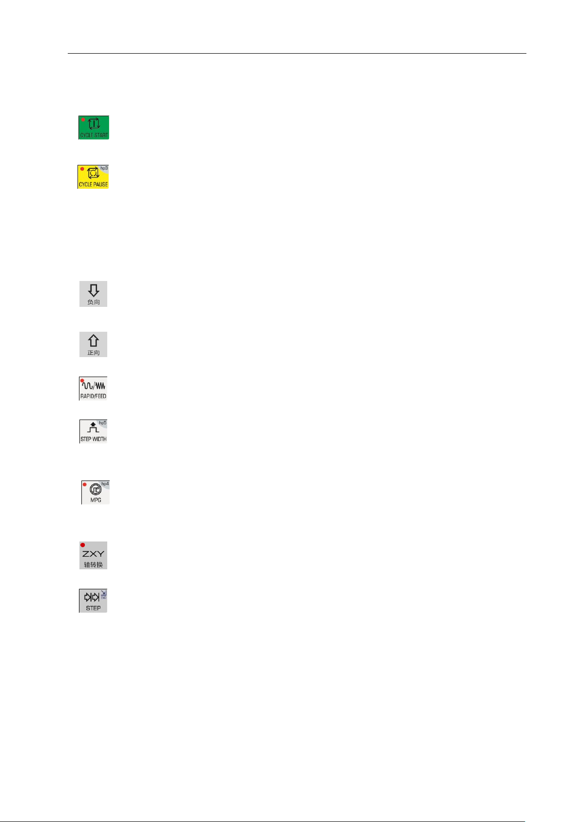
3.3.4 Cycle start and cycle pause (feed hold) key
Start and pause programs in AUTO working mode and each key symbol definition are as follows:
CYCLE START: Start to run programs in AUTO working mode; move coordinate axis in
JOG working mode.
CYCLE PAUSE (FEED HOLD): pause the running in JOG or AUTO working mode; hp
function in other working modes.
3.3.5 Manual axis control key
Manual key symbol definitions in JOG working mode are as follows:
X/Y/Z axis moves negatively in JOG working mode.
X/Y/Z axis moves positively in JOG working mode.
RAPID TRAVERSE/FEED Switching rapid traverse and feed in JOG working mode.
JOG STEP Select each step width or MPG feed in STEP/ MPG(Handwheel) working
mode; hp function in other working modes.
MPG (Handwheel) MPG control selection and axis selection in JOG working mode; hp
function in other working modes.
X/Z/Y and MPG axis selection in JOG working mode.
STEP/JOG mode Switch STEP/JOG mode in JOG working mode.
3.3.6 Manual auxiliary function key
The following press keys are used to control and complete all miscellaneous function of the machine
and each key symbol definition is as follows:
Page 24
GSK96 Multi-function Position Control System User Manual
6
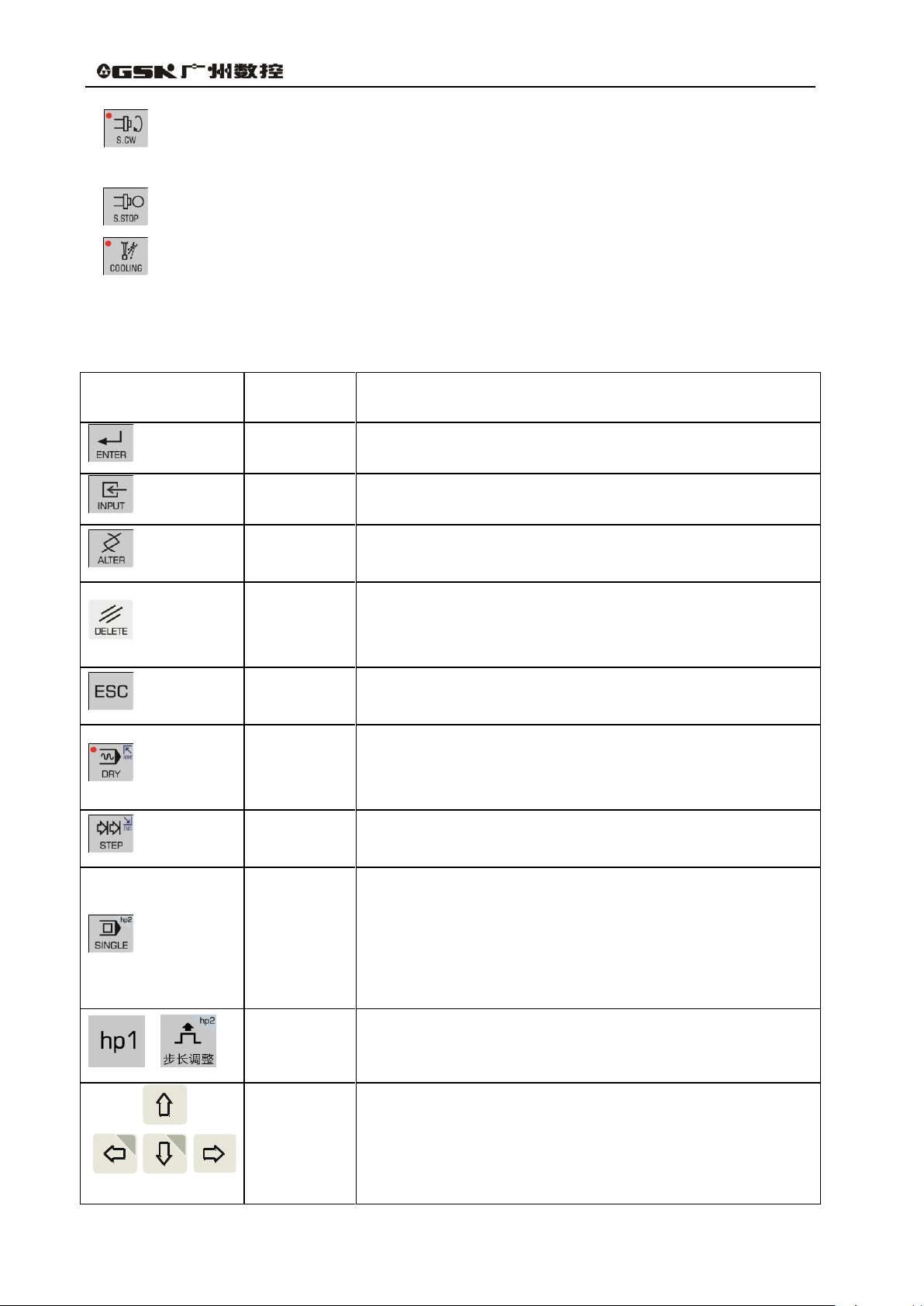
Press key
Name
Function explanation
ENTER key
Press it after the corresponding operation is performed.
INPUT key
Input the required content.
ALTER key
Switch character insert/alter state in EDIT working mode;
Special definition in other working modes.
DELETE key
Delete character, letter, block or whole program in EDIT
working mode;
Special definition in other working modes.
ESCAPE
key
Cancel the current input data or exit from the working state;
exit from the current operation or setting.
HOME key
―DRY RUN‖ in AUTO working mode;
Cursor moving to the beginning of the current line in EDIT
working mode.
END key
―STEP‖ in JOG working mode;
Cursor moving the end of the line in EDIT working mode.
SINGLE
BLOCK key
―SINGLE/CONTINUOUS‖ executing programs in AUTO
working mode;
―SINGLE/CONTINUOUS‖ analog executing programs in
AUTO working mode;
hp function in other working modes.
Help key
Two help keys: h1~h2
When step adjustment is invalid, h2 is valid.
Cursor
movement
key
Control cursor movement in EDIT/PARAMETER/OFFSET
working mode;
Hp function or other special definitions in other working
modes.
hp1
hp0
Spindle rotation (CW) Spindle rotates clockwise. (View from tailstock to chuck along
the spindle)
Spindle stop Spindle stops.
Cooling control Switch cooling ON/OFF.
3.3.7 Edit keys
Page 25
Operation Chapter Three System Operation Panel
7
Press key
Name
Function explanation
PAGE
UP/DOWN
Display page up/down in EDIT/PARAMETER/OFFSET;
Special definition in JOG /AUTO working mode.
Press key
Name
Function explanation
RESET key
Reset
3.3.8 Reset Key
.
Page 26
GSK96 Multi-function Position Control System User Manual
8
Chapter 4 System Operation
This chapter introduces operations and notes of the system. Please read carefully before operation.
4.1 System ON/OFF, Initial State, Modal, and Safe Protection
4.1.1 Power on
There is no power switch on the operation panel of the system. The operator installs it according to
the different machine to avoid bad effects to CNC system owing to the impaction of power supply.
Check before the system is turned on:
1) Ensure the machine state is normal;
2) Ensure the voltage meets the requirements;
3) Ensure the wiring is correct and firm.
The system is turned on as follows:
1) The master power switch of machine is turned on.
Switch on the power switch of the CNC system, and the system displays as Fig. 4-1. Press
any keys, and the system enters into EDIT working mode.
Fig. 4-1 System initialization display window
2) The system orderly completes the following work after power-on:
The system controls the program loading.
The system automatically checks itself and executes the initialization.
The system loads and checks parameters.
I/O interface initialization.
The system loads and checks the operator programs.
【Note】
1) Must not press any keys on the system panel when the system is turned on. Press
RESET key when the system enters the press key test window at the moment.
4.1.2 Power off
The system is turned off as follows:
1) The power switch of the CNC is turned off.
2) The power switch of the machine is turned off.
Check before the system is turned off:
Page 27

Operation Chapter Four System Operation
9
System state
Initial mode
Modal
Machine coordinate system
of the system
Keep last power-on state
Keep till being changed
Tool nose coordinate system
of the system
Keep last power-on state
Keep till being changed
Cutting feedrate:F
In Auto mode:30mm/min
Keep till being changed
In JOG mode: Keep last power-on state
Frequency conversion spindle
speed:S
S200
Keep till being changed
Spindle gear
Shifting gear spindle gear:S0
Keep till being changed
Conversion spindle gear:M41
MANUAL slow feed/rapid feed state
Slow feed
Keep till being changed
Feedrate override
Keep last power-on state
Keep till being changed
Rapid override
Keep last power-on state
Keep till being changed
Spindle state
M05 spindle stop
Keep till being changed
Cooling state
M09 cooling OFF
Keep till being changed
Chuck state
M11 chuck release
Keep till being changed
Lubricating state
M33 lubricating OFF
Keep till being changed
T number state
Keep last power-on state
Keep till being changed
Tailstock state
M79 tailstock run-out state
Keep till being changed
Set spindle speed/position mode
M48
Keep till being changed
1) X, Z, Y are in the stop state;
2) Miscellaneous function(spindle, cooling) OFF;
3) Turn off the power supply.
【Note】
1) The system should be checked itself and initialized when it is turned on at first (it is
completed by the machine manufacturer, and the operator cannot execute the operation,
otherwise, the parameter set by the machine manufacture will lose).
2) Operations related to turn off the machine power supply are referred to the operator manual
machine manufacturer.
4.1.3 System, program initial and modal
4.1.3.1 the initial state and modal of the system
The initial mode of the system is defined to be a special initial state of all functions set by itself when
the system is turned on; all auxiliary functions do not execute the actual output.
The modal of the system is defined to be their kept states after the system executes all functions.
Initial mode and modal of the system:
4.1.3.2 Initial mode and modal of program
The initial mode is the automatic initialization setting state before the system executes the machining
program; i.e. the initial default state of the default programming word and speed word.
Program initialization state of the system:
G command:G00, G97, G98;
Cutting speed:30mm/min;
Miscellaneous function: current state;
System coordinates: current coordinates are those of the last automatic executing
program or manual operation
G modal is always valid till it is changed by other modal commands in the same group after the
word is set. After the modal meaning is set, the G command may not be input again when the
Page 28

GSK96 Multi-function Position Control System User Manual
10
same function is used in the later block.
There are three groups of G command with modal characteristics, and there is only one
command in the modal state:
Group 1:G00, G01; (initial mode:G00 ) ;
Group 2:G96, G97; (initial mode:G97 ) ;
Group 3:G98, G99; (initial mode:G98 F30 ) ;
The command without modal characteristics has effect in the block and must be defined to use every
time.
【Note】
In AUTO working mode, the system automatically recovers to the program initial mode when it
executes the first command of workpiece program or executes the first block command after M20, or
selects the middle block as the first command.
4.1.4 Safe protection
The CNC system sets a perfect protection measure to prevent the operator from danger and the
machine from being damaged.
4.1.4.1 Hardware limit protection
The system can check the travel limit switch installed on the machined. When the machine slide
moves to press the travel limit switch, the system stops feeding instead of closing other
miscellaneous functions, and the program stops running and the system displays the hardware limit
alarm information of corresponding axis.
After the travel limit switch alarms, the system can select JOG working mode, the key for axis
movement which is reversed to the limited direction is pressed, i.e. the system exits the travel limit
and the travel limit switch alarm automatically disappears on the screen.
【Explanation】
1) X, Y, Z positive limit check shares one pin LT+, and their negative limit check shares one pin
LT-; when the positive limit alarms, all axes cannot move positively but move negatively; and
vice versa.
2) When the travel limit switch runs across the limit block, the limit signal appears; the valid
length of limit block signal is more than 30mm or more to avoid rush out the valid area of the
signal.
3) When the parameter is set to ―limit emergency stop‖ mode (bit parameter P402_d7=1), and
the system runs across the limit block, there may be great deviation between the coordinates
displayed by the system and the actual position. Adjust the machine coordinates.
【Relative parameters】
Bit parameters: P402_d7, P404_d6, P404_d1.
Bit parameter P402_d7 sets the hardware limit alarm mode;
Bit parameter P402_d6 sets whether the hardware limit alarm checks;
Page 29
Operation Chapter Four System Operation
11
Bit parameter P402_d1 sets the hardware limit alarm level of each axis;
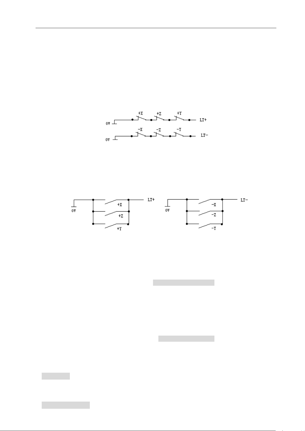
When P404_d1=1 is high level alarm, the positive limit switch +X, +Y, +Z of each axis are normally
closed contact, are connected to X/Z/Y positive limit input interface +LT (they are open and the
system alarms) in serial; the negative limit switch -X, -Y, -Z of each axis are normally closed contact,
are connected to X/Z/Y negative limit input interface -LT (it is off and the system alarms) in serial; it is
suggested that the operator should select in prior the hardware limit to the normally closed contact of
each axis as follows:
When P404_d1=0 is low level alarm, the positive limit switch +X, +Y, +Z of each axis are normally
open contact, are connected to X/Z/Y positive limit input interface LT+ (they are closed and the
system alarms) in serial; the negative limit switch -X, -Y, -Z of each axis are normally open contact,
are connected to X/Z/Y negative limit input interface LT- (it is off and the system alarms) in serial; the
connection is as follows:
4.1.4.2 Software limit safe protection
1) Mechanical software limit safe protection
The mechanical software limit safe protection is to limit machine coordinate motion range to
avoid slide to exceed the motion range. The mechanical software limit alarms when the machine
position (machine coordinates) exceeds the range.
Releasing overtravel alarm methods: reversely movement in JOG working mode (negatively
moves for positive overtravel; positively moves for negative overtravel).
2) Tool nose software limit safe protection
The tool nose software limit safe protection is to limit tool nose coordinate motion range to avoid
the tool nose to exceed the motion range. The tool nose software limit alarms when the machine
position (tool nose coordinates) exceeds the range.
Releasing overtravel alarm methods: reversely movement in JOG working mode (negatively
moves for positive overtravel; positively moves for negative overtravel).
【Explanation】
1) The coordinate axis decelerates to stop when the coordinates exceed the software limit range
during the motion.
【Relative parameters】
Page 30

GSK96 Multi-function Position Control System User Manual
12
P009, P010: max. travel of Z positive, negative tool nose software limit; P011, P012: max. travel of X
positive, negative tool nose software limit;
P013, P014: max. travel of Y positive, negative too nose software limit; P015, P016: max. travel of Z
positive, negative mechanical software limit;
P017, P018: max. travel of X positive, negative mechanical software limit; P009, P010: max. travel of
Y positive, negative mechanical software limit;
Bit parameter P404_d4, P404_d3 separately sets whether the mechanical, tool nose software limit
alarm are valid.
4.1.4.3 Emergency stop alarm (emergently stopping the system)
When there is the external emergency stop input terminal ESP in the system input interface, the
operator should connect the emergency stop button Normally closed contact on the machine panel
with the emergency stop input terminal. Press Emergency stop button and the system enters the
emergency stop state. The system stops all feed and sets the output of all the switch value control
such as the spindle and the cooling to be invalid, disaplying ―Emergency Stop Alarm‖.
After the emergency stop condition is released, the operator should rotate the emergency stop
button clockwise based on the up arrow, the button automatically releases to cancel the emergency
stop signal.
When the system is in the emergency stop alarm state and the external emergency stop signal is
cancelled, you can press the ―RESET‖ key to return the previous working mode.
When the system is in the emergency stop state, if the external emergency stop signal is not
cancelled, it is forbidden to operate the system in Manual, Auto and Diagnosis operations; but the
user can press RESET key to remove the alarm window, and switch the control to Edit, Parameter or
Tool Offset operation mode.
If the emergency signal is not cancelled in Edit, Parameter or Tool Compensation operation,
press RESET key to remove the alarm window, then it is available to operate system.
There is the Emergency stop in the movement, there may be great deviation between the
coordinates displayed the system and the actual position, and the operator must correct the machine
coordinates.
When emergency button is pressed, there are a series of procedures to be handled:
1) During emergency stop, the system stops all feed, and terminates program execution; the
spindle stops rotating; cooling and lubricating function is turned OFF.
2) During emergency stop, the system automatically sets the internal stored chuck and tailstock
states to M11 and M79. After the emergency is released, when the foot switch of chuck or
tailstock is pressed for the first time, the states become M10, M78.
3) During emergency stop, if such commands as tool exchanging, tailstock, chuck, gear
changing is being executed, the execution should be stopped immediately (cancel the tool
post CCW/CW signal; tailstock signal and chuck signal are depends on parameter setting); at
this time, the system assumes that the tool post, chuck, tailstock and gear are not in the
Page 31

Operation Chapter Four System Operation
13
proper position, and red indicator is flickering; only when the emergency stop alarm is
released, and above execution is repeated or after system power-on, can the system resume
the normal state.
4) During emergency stop, if the output signal of MDLY interface remains the same, interface
control signals other than MDLY, spindle , cooling, lubricating are set by parameters. If
P403_d3 is 0, then, only output signals for spindle, cooling and lubricating are turned off; if
P403_d3 is 1, all interface control signals including chuck and tailstock signals are turned off.
5) After the emergency stop alarm is cleared, in AUTO mode, the system will exit from dry run
state if it was; in MANUAL mode, the system will turn from rapid traverse state to feed state; if
the set F value is not changed, the spindle analog voltage output remains the same; except
for that, other functions of the system are in initial state.
6) After the emergency stop alarm is released, time counting of the low-pressure detection
function and auto-lubricating control function are restarted.
【Special Attention】
1)The standard emergency stop function is actually to set the output signals to ―ON‖ or ―OFF‖. It
can be like this: In MANUAL/AUTO mode, when emergency stop button is pressed, the
standard emergency stop is executed, in addition, M74 user-defined command is also
executed (it is executed only when there is already a M74 command in the system). This
function is applicable to some special machine parts under the requirements of keeping some
output signals ON while turning OFF some others. If any similar alarm occurs during the
execution of M74, the execution stops. During emergency stop, if the M74 command is
executed, and axis movement or tool change is being carried out, the system will stop M74
execution automatically.
2) In MANUAL/AUTO mode, when the parameter sets that M74 can be executed during
emergency stop (P412_d1=1), the pop-up window displays ―+M74‖. (When there is already
a solidified M74 command in the system.)
3)For more details about M74, please refer to Chapter 8.
4)Please be careful when executing M74 function. It is only suitable for some special machine
tools.
【Relative parameters】
The external emergency stop signal function is valid when P404_d7 is set to 0.
The external emergency stop signal function is invalid when P404_d7 is set to 1.
P403_d3=0:When the emergency alarm is valid, the system only turns off the signals of spindle,
cooling and lubrication.
P403_d3=1:When the emergency alarm is valid, the system turns off all the output signals of
the auxiliary function.
P404_d7 is for debugging the system, and must be set to valid in the power-on state; otherwise,
Page 32

GSK96 Multi-function Position Control System User Manual
14
it cannot provide protection.
P412_d1 parameter sets whether to execute M74 self-defined command during emergency
stop.
4.1.4.4 Drive unit alarm
When the system is connected with the alarm output signal of a drive unit and appears Drive unit
alarms, the system automatically closes all feed and prompts Z/X/Y drive unit alarms. All axes
immediately stop motion, and the program stops running. At the moment, check the drive unit and
relative device to troubleshooting and the system is turned on again.
When there is the alarm in the course of motion, there may be great deviation between the
coordinates displayed the system and the actual position, and the operator must correct the machine
coordinates.
In JOG working mode, the system prohibits all axes moving when there is the alarm.
In AUTO working mode, the system prohibits the program starting run when there is the alarm.
【Relative parameters】
The drive unit alarm checks when P404_d5 is set to 0.
P405_d4, P405_d3, P405_d2 separately sets alarm level of Z, X, Y drive unit.
4.1.4.5 Other alarms
When the system appears other alarms, Chinese characters prompts, at the moment, the operator
can perform the troubleshooting based on PROGRAMMING, Chapter 6 Alarm Message.
4.1.4.6 Switching off power supply
The machine power supply is switched off immediately to avoid the accidence in the danger or other
emergency cases when the machine is running.
Note: When the coordinate axis is moving and the power supply is switched off, after the machine is
switched on again, there may be great deviation between the displayed coordinates and the
actual position, and so the operator must execute the machine zero return or other ways to
regulate the machine coordinates to ensure that the displayed coordinates are the same as
those of the actual.
4.1.4.7 Reset operation
When the system outputs abnormally and the coordinate axis moves abnormally, the operator should
press to make the system be the reset state as follows:
1) All axis motions decelerate to stop;
2) Whether M function output is valid is set by P403_d2.
3) The automatic run ends, the modal function and state keep.
4)After the pressure low alarm occurs, press RESET key, the system will remove the alarm, and
Page 33

Operation Chapter Four System Operation
15
【Special attentions 】
1) The standard Reset function executed by the system is the function of turning on or turning off the
system output signals uniformly. The following function can be set: In Manual/Auto operation,
after Reset button is pressed, and the system executes the standard Reset function, the system
executes an additional M73 custom command (only when in Manual/Auto operation mode and
when there is a solidified M73 command in the system, the execution is available). This
function is applicable to some special machine components and is used when only some of the
output signals are required to turn off and some maintained. If there is an alarm occurs during the
execution of the M73 custom command, the execution is stopped.
2) In Manual/Auto operation mode, when the M73 custom command can be executed in Emergency
Stop state by setting a parameter (P412_d2=1), there is a prompt ―+M73‖ ( indicating the M73 is
being executed) added on the reset window (if there is a solidified M73 custom command in the
system).
3) For the programming, debugging and fixing of M73 custom command, please see Chapter Eight
―Custom Command Programming‖ in this manual.
4) Be careful to use M73 custom function during Reset. The function is only applicable to some
special machine tools.
re-clock to detect the pressure low alarm signal.
5)When the system is in G00,G97,G98 state, both F value and spindl analog voltage output
keep unchanged.
6)The system terminates the operation in progress, and returns the control to the initial interface
of the current operation mode.
【Relative parameters】
P403_d2=0: the system closes M03, M04, M08, M32 output signals when the reset key is
pressed.
P403_d2=1: the system does not close M03, M04, M08, M32 output signals when the reset key
is pressed.
Parameter P412_d2 sets whether M73 custom command is executed during Reset.
4.2 CNC Working Mode Selection
The system uses the working mode key to directly select the all working modes. All working modes
can direct switch to get the simple and convenient operations.
The display is as Fig. 4-1 after the system is turned on, and the display state keeps till the other key is
pressed to enter the EDIT working mode.
Page 34

GSK96 Multi-function Position Control System User Manual
16
EDIT working mode: it is the working mode to execute the part program by the operation panel.
There is the corresponding intelligent prompt message for each operation. At the same time, the
operator can press the prompt key- hp1 at the top right to learn the operation key list in EDIT working
mode.
The relative setting or operation key format and sample descriptions in the user manual are as
follows: meanings and uses of all required functions are described at the beginning of the
corresponding chapter; all required letter and digit keys are expressed with underlines; the system
prompt messages are expressed with borders.
In executing some setting or input or man-machine dialogue, press ESC key to exit the current
operation before key is not pressed.
Program length 1KB
EDIT
Program count:45
%
000
1KB
G00 X0
%
001
1KB
G0 X115
%
0022
KB
G50 X150
%
020
1KB
G00 X300
%
0302
KB
G50 X250
Name size remark
Name size remark
EDIT
DGN
PAR
OFT
AUTO
JOG
Current program No.
020
Upper top
Middle top
Pop-up window
Lower bottom
Middle
Middle bottom
Openning U disc. Please
wait…
Program remaining space: 792KB
hp1
4.3 EDIT Working Mode
◆ Main functions in Edit mode include:
☆ select, create, rename, copy and delete part programs;
☆ input, insert, modify and delete the content of the selected part program;
☆ transmit part programs between U disc and the system by the USB interface;
☆ compile and save program;
☆input variable and macro character string.
Press to enter the EDIT working mode. The EDIT working mode includes two main
window: program catalog search window and program edit window. The program catalog search
window is as Fig. 4-2:
Fig. 4-2 program catalog search
◆ Display content in window area:
Upper top: program number and capacity of current program(program length), the system
function operation method prompt key hp1;
Middle top: orderly arrange program name, capacity, latest remark;
Page 35

Operation Chapter Four System Operation
17
Middle: display program name, capacity and remark;
Middle bottom: operation prompt message;
Lower bottom: display current stored part program quantity (up to 255) and surplus stored space;
Pop-up window: display operation prompt message.
【Note】
Press hp1 key, and the system prompts ― Program catalog window message prompt‖, introducing
the used press key functions.
4.3.1 Part program catalog search
Program catalog search window displays the current stored program quantity, and all programs sorts
as follows:
1) name: program number from top to bottom, from left to right;
2) size: program stored space from top to bottom, from left to right;
3) remark: the first 12 characters of the first line of the program from top to bottom, from left to
right;
4) the latest: input time sequence from top to bottom, from left to right.
Press , and , , the system searches all part programs, displaying 12
program on each window; press to the first page of program, to the last. Press
, to sort all programs according to their name, size, remark and last distribution.
4.3.2 Selecting, creating, deleting, renaming and copying a part program
Select, create, delete, rename and copy part programs
【Note】
1) The system executes most %000~%254 programs, 255 program names. The system
prompts E160 input program error when the executed program name is more than 254.
2) There is no part program or the system is not used firstly, the system automatically creates
and selects %000 program as the current program. When there are programs, the system
sorts the program according to part program quantity and program names in the last
power-off.
3) The system supports many input, the leading zero cannot be input. Example, inputting %003
program. Press INPUT, input 0 0 3 ; also input 0 3 ; or input 3.
4.3.2.1 Selecting and creating a part program
The operations to select a part program or create a new program are as follows:
① Press INPUT key in EDIT working mode;
Page 36

GSK96 Multi-function Position Control System User Manual
18
② Input the required program number by the board key, or input a program number which is
not in the program catalog list as the new program number;
③ Press ENTER key;
④ Select or create a part program, display the content of the part program, and the system
enters the program edit window.
【Note】
1) When a program is selected, it is changed by the above steps; it cannot be changed once it
is confirmed.
2) When a program number which is not exist in the part program catalog, the newly created
program is taken as the current program.
【Example】
Example 1:there is no %20 part program in the part program catalog, creating it is as follows:
Press keys to input: INPUT 2 0 ENTER. The new program %020 has been
created and the system enters %020 program edit window.
Example 2:there is %001 part program in the part program catalog, select it is as follows:
Press keys to input: INPUT 1 ENTER. The selection of %001 part program is
completed, the system enters %001 program edit window.
4.3.2.2 Delete a part program
Delete a part program is as follows:
① Press INPUT key in Edit working mode;
② Input the required program number to delete by the key board;
③ Press DELETE key, the system prompts: Enter-confirm the deletion Esc-escape the deletion .
④ Press ENTER to delete the part program which program number is input. Press ESC not to
execute the deletion operation and return to EDIT working mode.
【Note】
1) The system displays E100 the program to be deleted does not exist when there is no the
program to be deleted;
2) When the program which is to delete exists: when it is not the current program, the system
deletes the program from the program list; when it is the current program, the system deletes
the program from the program list, and searches the program which program number is the
smallest to be the current program; when there is no programs, the system creates one
program number 000 as the current program.
【Example】
Example: delete %003 operation is as follows:
Input by the press key: INPUT 3 DELETE ENTER.
Page 37

Operation Chapter Four System Operation
19
4.3.2.3 Deleting all part programs
Clear the program area in the program catalog search window, and all programs in the system are
deleted as follows:
① Press INPUT in the part program catalog search state;
② Input , by the key board;
③ Press DELETE , the system prompts: Enter-delete all programs Esc-escape the deletion .
④ Press ENTER to delete all part programs; press ESC not to execute the deletion operation
and return EDIT working mode.
【Note】
The system creates a program number 000 as the current program after all part programs are
deleted.
P416_d6 sets whether all the programs can be deleted in EDIT operation mode.
4.3.2.4 Renaming a part program
The program name of the current program is renamed as another new one. The new is taken as the
current program is as follows:
① Press INPUT key;
② Input the program number which is not in the program list, press ALTER and the current
program number is rewritten to the input program number.
【Note】
When the input program exists, the system prompts E166 required renaming program already
exists.
【Example】
Example: the current program %000 is renamed to %005 as follows:
Press key input: INPUT 5 ALTER . And the renaming is completed.
4.3.2.5 Copying a part program
Copy the current program content to another one new and the new becomes the current program as
follows:
① Press INPUT key;
② Inputting the program name which is not in the program list, press INPUT key and the
current program content is copied to the new program. The new program is taken the
current one.
【Note】
Page 38

GSK96 Multi-function Position Control System User Manual
20
When the input program name exists, the system prompts E161 program to be copied
already exists and waits the prompt losing to input a new one.
【Example】
Example: copy the current program %000 to %005 as follows:
Press key input: INPUT 5 INPUT. The copy operation is completed.
4.3.3 Part program communication
The communication of part programming includes the sending and receiving the part program. The
sending mode is: the system outputs to U disc (CNC→USB) ; the receiving mode is: U disc inputs to
the system (USB→CNC)
Press hp2 in the program catalog search window, the system opens the U disc to enter the
communication interface.
4.3.3.1 Sending part programs (CNC→USB)
USB communication;
1) After entering USB communication mode, the system first checks whether a U disc has been
inserted. If no U disc is inserted, the system displays a prompt message box, prompting No
USB device inserted . If a USB disc containing a folder named ―C001PRO‖ has been inserted,
and there are CNCxxx.TXT files in the folder, the files will be listed on the USB file directory
box. If there are no CNCxxx.TXT files in the C001PRO folder, the system prompts: USB
device specified directory: C001 PRO has no programs. If the folder named―C001PRO‖does
not exist in the U disc, the system prompts: No specified directory in USB device: C001 PRO
2) Output the part program stored the system to U disc as follows:
① Insert U disc in the system USB interface;
② The system automatically opens U file catalog(create a file in the U disc: C001PRO,file
format CNCxxx.TXT) . The system creates ―C001PRO‖ when there is no ―C001PRO‖ in the
U disc root catalog.
③ In program search page, press key to input :hp2 ;
④ Select the required programs to send according to the system hp1 help message.
⑤ Press ENTER to send and the system prompts to select the sending mode;
⑥ The system outputs the selected programs based on the selected sending mode and
displays the sending process till the sending is completed;
⑦ Select ESC to exit from U disc.
4.3.3.2 Receiving part programs(USB→CNC)
USB communication;
1) After entering USB communication mode, the system firstly checks U disc, and opens
―C001PRO‖ existed in the U disc and lists ―CNCxxx.TXT‖ file.
2) Output part program stored in U disc to the CNC system as follows:
Page 39

Operation Chapter Four System Operation
21
① Insert U disc in the system USB interface;
② Press key to input:hp2 → Edit;
③ The system automatically opens U disc file catalog;
④ Select the required programs to receive according to the system hp1 help message;
⑤ Press ENTER to receive and select the sending mode according to the system prompt;
⑥ Input the programs according the selected receiving mode, display the receiving process
till the receiving is completed;
⑦ Select ESC to exit from the U disc.
【Note】
If the stored program name is the same as the sent program name, a prompt will be displayed
for you to determine whether to replace the original program or not. If you choose yes, the
original program will be replaced by the received one.
4.3.3.3 TXT part program standard format in U disc
Use TXT, LST text to edit part program in U disc, but the file name must be compiled based on the
standard format required by the system to be sent to the system as follow:
1) Name the file name of the part program to TXT or LST suffix, such as ―CNC008.TXT‖ in PC;
it is suggested that the operator use TXT suffix to conveniently execute part programs on the
PC.
2) The first line of TXT file content must specify the program number, its format is ―% XXX‖, i.e.
percent sign follows the digit 1, 2 or 3, its range is 0~254, and the first line cannot have other
content. Its range must be 0~254 because the program number created and stored by the
system is 0~254, otherwise, the system cannot receive the programs and prompts the
corresponding mistaken message. The program numbers received by the CNC are
determined by the following method:
◆ The program number sent by the system USB is digit xxx of CNCxxx.TXT in―C001PRO‖
file folder in the U disc root catalog.
Note: in USB communication, the character string XXX digit of %XXX” in the first line should be
the same that of xxx digit of CNCxxx.TXT. When they are different, the xxx digit of CNCxxx.TXT is
taken as the standard.
3) The blocks start from the second block. The block must meet its format. Each block cannot
exceed 250 characters, ends with the ENTER key, otherwise, the system prompts the error:
Block too long in received programs.
4) The annotation area has Chinese annotation in the block.
5) Max. TXT file length cannot exceed the program stored space limit of the system.
6) You can refere to the part program file format that the system outputs to the U disc.
Part program communication standard format in U disc:
Page 40

GSK96 Multi-function Position Control System User Manual
22
TXT file format
Explanation
%099
N0000 G50 X100 Z100 ; Sets coordinate system
N0010 G00 X20 Z90 ; Rapid positioning
G01 X10 Z80 ; Linear cutting
……
/N0250 G01 X30 Z20 ; Linear cutting
N0260 M05
N0270 G04 D8
……
M20
1. There must be program name %099 when
the system receives programs; the first line
must the 3-digit 0~254+.
2. “N****” are the blocks with the line number,
and others are the blocks without the line
numbers;
3. The home of each line must be blank;
4. there is a space between the line number
and the command for the program with the
line number;
5. / block skip;
6. ; the following is the annotation.
【EDIT】 %001 RW 8 Ln 3 Lines 11 SIZE 1KB hp2
N0000 G0 X100
N0010 X0
N0020 X100
N0030 X0
N0040 G1 X100 F80
N0050 X0
N0060 X100
N0070 X0
N0080 X100
N0090 X0
N0100 G1 Z100
N0120 M20
Middle
Top
Current editing program is
compiled successfully
Pop-up
window
Fig. 4-3 program edit
4.3.4 Part program content input and edit
Each input part program consists of many block, and each block is composed of block number,
command and data. The program format must meet the general programming rules, and there is no
prompt in program compiling, and the alarm prompts are referred to PROGRAMMING, Chapter 6
Alarm Message. The qualified parts can be machined only according to the technology requirements
and orderly input correct program contents.
The edit mode of the system is full screen. The program edit window is displayed as Fig. 4-3:
◆Display content in window area:
Upper top: program number, program capacity(program length) and program line quantity of
current program, edit cursor line and row (prompt symbol of current editable character
position), and the system function operation prompt key hp2;
Middle: program edit window;
Pop-up window: display operation prompt message.
【Note】
1. Press hp1, the system prompts “Program edit help message prompt”, introducing
all help key explanation.
2. When P416_d0 is set to 1, the system forbids pressing key to edit and modify
programs, and prompts the alarm E174:machining programs are locked and are
forbidden to modify; when the system edits and modifies the programs, P416_d0
should be set to 0.
Page 41

Operation Chapter Four System Operation
23
Edit key meanings and use in program edit window:
1) , cursor UP, DOWN move key: Press the move key every time, and the
cursor moves up(down) till the top (the bottom) line. Keep pressing the moving key and the cursor
continuously moves up(down) till the first(last) line or the move key is releases. In the character string
search function(hp1) , the operator can search the required character string up and down.
2) , cursor LEFT, RIGHT movement key: Press the move key every time, and
the cursor moves left(right) one character. Keep pressing the moving key and the cursor continuously
moves left(right) till the first(last) character or the move key is releases.
3) Home key: the cursor rapidly moves to the home or the first field head of the line.
Press continuously the head key, and the cursor switches between the head and the first
field of the line. The compound of the head key and the deletion key can delete the current
line.
End key: the cursor rapidly moves to the end of the line.
4) insert/alter: Changing edit input mode: switch the insert and the alter after pressing
it once. The cursor also changes correspondingly and the insert mode cursor flashes to be
one horizontal line, and the alter mode cursor flashes to be the high light square.
5) input key: The program edit state is switched into the program catalog search state,
and the system prompts Input program number: .
6) Page Up, Page Down: Paging to display the program content. In hp1, the
cursor directly moves the home/the end window1.
7) Enter key: When the cursor is in the first line or the last line, press ENTER, it will
locate to the new line.
8) delete key: Delete all blocks or characters in the block.
9) hp1 key:Program edit help message prompt.
10) hp2 key:Current program compiling.
Multi-function definition key input must obey the following rules:
Page 42

GSK96 Multi-function Position Control System User Manual
24
1) When the first letter is capital in the line, the first key value is prior; when it is the lowercase,
the 3rd or 2nd key value is prior.
2) The system automatically creates the blank space when the letter or character following the
digit (0~9) is input.
3) The cursor stays the position where the input is convenient after the character string is input.
4.3.4.1 Inputting program content
Note: P333 is set to 10 (the system automatically creates the block number, and the following
is the same).
In program edit window, inputting the part program content is as follows:
① create a new program according to the operations of creating new part program;
② input one line content after the block N0000 is displayed;
③ press ENTER key after inputting one line programs to end the line input;
④ the system automatically creates the next block number and continuously input the program
content;
⑤ press ESC to complete the program content input after the last line programs are input.
【Note】
1) The first row of every line only displays the blank space;
2) Each block only displays 60 characters, and only the first 60 characters are displayed when
there are more than 60 characters, you can press to left move one character.
3) The serial number of the first row blank is 0, the last is 251, and the system only displays the
cursor instead of the character; there are up to 250 characters in the edit line; i. e. the first
blank bit +250 characters+ the last cursor bit character=252.
4.3.4.2 Inserting program line
Insert one or many program line between two program lines or in the front of the current block as
follows:
① Move the cursor to the first block end or the last block home of the two blocks;
② Press ENTER, and the system automatically creates a new block number between the
current block and the next (the serial number increment is P333 parameter 1/4 integer, the
next block number can be modified when the above the increment is not enough) and
remains a blank line.
③ Input the required block content;
④ After all content is input and many line are required to insert, ENTER is pressed, which is not
done when one line is required to insert.
【Example】
Page 43

Operation Chapter Four System Operation
25
Example: insert a new block M3 between N0020 and N0030 as follows:
Move the cursor to the end of block N0020 or the beginning of block N0030; Press
ENTER key, and input M3.
4.3.4.3 Deleting a block
Delete all content in one line as follows:
① move the cursor the home of the required line;
② press DELETE;
③ delete all content of the selected line.
4.3.4.4 Inserting a character in a block
Insert a character in one block as follows:
① Press ALTER, switch the input mode to insert mode, i.e. the cursor is displayed to the down
horizontal line;
② Move the cursor to the character following the required insert position;
③ Input the required insert content;
④ Insert the input content before the character pointed by the cursor.
【Note】
The CNC system requires there is a blank space between fields in the program line. In editing
program, the system can automatically judge and create a blank space, but cannot automatically
judge in the insert operation, and at the moment, the operator should input a blank to get the
complete program.
【Example】
Example: insert 1 between X and 0 in N0020 G0 X0.0 Z0.0. As follows:
The cursor moves the under 0 following X input 1 , displaying N0020 G0 X10.0 Z0.0
4.3.4.5 Deleting a character in a block
Delete the content which is not needed as follows:
① Move the cursor to the character position which is needed to delete;
② Press DELETE to delete the character.
4.3.4.6 Modifying a block content
Modify the content of the block into the new, which can be complete according the input
mode(insert/alter).
In INSERT mode, use the insert and deletion as follows:
① Move the cursor the character which needs to be modified;
② Input the new content;
③ Press DELETE to delete the required content.
Page 44

GSK96 Multi-function Position Control System User Manual
26
In ALTER mode, directly modify the content as follows:
① Press ALTER; the cursor switches into the alter mode(the character position pointed by the
cursor is high light square);
② Move the cursor to the character which needs to be modified;
③ Input the new content. The cursor points the next character.
【Example】
Example: alter X in N0020 G0 X0.0 Z0.0 into U as follows:
Switch the input mode into ALTER mode, move the cursor to the down of X and input U .
Alter to N0020 G0 U 0.0 Z0.0 .
4.3.4.7 Program stored space
For programs No. 0~252, No. 254, the system provides 400K memory space, so theoretically,
the size of a single program can be up to 400K. For No. 253 program, the system provides 4M
FLASH memory space.
【Explanation】
1) The system displays the program leftover space and prompts the leftover stored space size.
2) When the current edit No. 0~252, No.254 program size are more than all stored space(max.
400K), the programs cannot be saved, and the system prompts the storage space has full:
Overflow in edit area. Delete the old programs when the leftover space is not enough.
3) Max. edit space of No. 253 program is up to 4M, and is only saved to the system FLASH.
4) In saving programs, the program capacity is big and saving the programs need long time, and
the operator needs to wait.
4.3.4.8 No. 253 program operation
Because No. 253 program is up to 4M, its solidifying and read are special as follows:
1) Only be saved to a fixed FLASH;
2) Select No. 253 program, press hp1 and then 4 to save it to the FLASH in program edit
window;
3) Can use USB to complete the communication.
【Note】
1) Program No. 253 cannot be saved automatically, and should be complied and solidified after
editing; otherwise, it cannot be saved. However, if the program No. 253 is transmitted from
USB successfully, the system will automatically save this program.
2) Program No. 253 cannot be copied or renamed.
3) Longer time may be needed when the saved program No. 253 is large.
4.3.4.9 No. 254 program operation
For No. 254 program, press hp1 in program edit window, the system prompts the help message
prompt box how to compile, solidify and read No. 254 as follows:
Page 45

Operation Chapter Four System Operation
27
1) Press 4 and read No. 254 program:
Read No. 254 program saved in FLASH area to the edit buffer zone, and update it.
2) Press 5 to compile and solidify No. 254 program:
Edit No.254 program. The system alarms when the edit is wrong; the system saves it to the
FLASH area when it is compiled successfully.
3) Press Key 6 to delete the custom command of No. 254 program
If there is a custom command in the solidification area, the command will be displayed on the
screen. After the custom command in No. 254 program is deleted, there is no custom
command in the system solidification area; the help information dialog box for No. 254
program prompts ―No custom command in solidification area‖
4) Press ESC to exit the current state.
4.3.5 hp1 function
Hp1 help key including the system command help, macro string insertion, line number sort, character
string replacing, cursor positioning and so on.
When the current program is No. 253 or No. 254, hp1 help key adds its operation prompt.
The movement of the MPG control cursor is controlled by MPG key.
4.3.5.1 Part program command help
In program edit window, press hp1 1 , the system prompts ―Command help introduction‖ window;
the function can search all commands of the system including G, M, S, T, F as follows:
1) G , M , S , T , F separately introduces G, M, S, T, F command.
2) press INPUT and input the command number to search; the system displays the definition, the
function, the format and the explanation of the command number.
【Example】
Example: search G01 command help.
Press :hp1 1 INPUT G 01 ENTRE, the system displays G01 definition, function,
format and explanation.
4.3.5.2 Inserting macro string
The procedure of inserting macro string on the program edit page is as follows:
① Press hp1 2 key to display the macro string list on the screen;
② Select the desired contents according to the keys;
③ In the list, the key value is in front of the colon, and the inserted string contents are behind the
colon.
【Example】
E.g. Press hp1 2 key, then press G key, program contents input: r = r * r / r, the cursot stays
behind the r.
Page 46

GSK96 Multi-function Position Control System User Manual
28
【Note】
For details about the variables and statement programming explanation, refere to Chapter Seven
Programming Statement.
4.3.5.3 Line number sort
Press hp1 3 in the program edit window, and the system sort again the programs, and the sorted
block number increases in 10 times. (P333 value is set to 10.)
【Note】
1) After sorting the block number again, the program skip error appears when the program skip
command is used in programming.
2) Program sorting function is invalid when P333 is set to 0.
4.3.5.4 Replacing character string
Press hp1 R in the program edit window, and the system prompts ― Character string replacing‖
window; the operator can execute the operation according to the system prompts. All characters
which need to be replaced are replaced from the character where the cursor is to the last character.
4.3.5.5 Cursor position
The system provides the character string search function, i.e position the content needed by the
operator, which is convenient for operator to search the required content. Press hp1, and the system
prompts , , , , F operation functions as follows:
1) Press and the cursor positions to the first page of the current program.
2) press and the cursor positions to the last page of the current program.
3) press F, input the character which is needed to search of the current program, press ENTER,
the cursor positions the character.
4) press , to search the character of current program according to the system
prompt. The system prompts Searching is completed and there is no character string when
there is the character which is needed to search of the current program.
4.3.5.6 MPG controlling cursor moving
After the system is connected with MPG, the operator presses MPG , rotates MPG to control the
cursor movement when the MPG key LED is light on the operation panel. Press MPG repeatedly,
MPG operation is invalid when MPG key LED is OFF. The concrete MPG connection is referred to
CONNECTION.
Page 47

Operation Chapter Four System Operation
29
4.3.6 Part program compiling
The system provides hp2 compiling command key to compile part programs, check the syntax error,
logic error of programs and coordinate data overtravel according to part program execution path to
reduce the alarm error in Auto mode and improve the safety of executing part programs.
Press compiling command key and the system orderly checks and compiles part programs from the
first line block, and creates convenient target command according to the execution path. When the
system finds out the mistaken operator programs, it stops the compiling, displaying the mistaken field
position and number in the line of the source program, prompting the operator to modify till the
mistaken is corrected.
4.3.6.1 hp2 compiling command
In program edit window, press hp2 and the system orderly compile the current program. The system
pops up a window『Program alarm』when it finds out a mistaken message. The system displays
Current edited program compiling is completed successfully when all command compiling are
correct.
『Program alarm』message includes as follows:
Error: mistaken command( refer to PROGRAMMING, Chapter 6 Alarm Message according
to the commands);
Program: content of mistaken block;
Position: mistaken letter or field of mistaken block.
【Explanation】
1) Program which is compiled successfully by hp2 can run in AUTO working mode.
2) The system automatically completes the compile when it switches from EDIT working mode
to other working modes.
3) Press hp2 to complete compile to appear『Program alarm』, and then press any keys and the
edit cursor automatically points to the mistaken block.
4) Executing hp2 compiling, the system assumes that the machine coordinate axis takes the
current workpiece coordinate position as the starting point, starts the execution from the first
block of the current program. So, for some special programs, each axis stopping position
has effect on the compiling; it is suggested that each coordinate axis should stop in advance
in the starting point of the machining.
4.3.6.2 Program compiling result analysis
In program edit window, the program compiling error creates two types of alarm: [Program alarm]
and[Program compound check alarm]. The program compiling is completed successfully there is
no the above alarm.
Program alarm: there are mistaken commands in programming to cause the alarm, and the correct
Page 48

GSK96 Multi-function Position Control System User Manual
30
In JOG working mode, the operator can directly press the function key to execute some operation, and also press the
letter key execute the some setting or execute some operation; the system provides the corresponding prompt
message for each operation.
The relative setting or operation input format and example are as follows: the required function key is expressed with
icon; the required input letter or digit key is expressed with the underline; the system prompt is expressed with the
frame.
Press to clear the mistaken digit and input it again when the mistaken digit is input in the course of inputting
letter or digit.
Press to exit the current operation before the confirmation when the operator sets some operation or
executes the input or man-machine dialog process.
[Program alarm]
Error E206:missing message
Line:11
Program:N0100 G92 Z300 P1
Position: P
[Program compound check alarm]
Error E610:have illegally used M78
The command function is invalid
command is input to clear the alarm, which is not related to the parameter setting.
Program compound check alarm: program command check causes the alarm, which is resolved by
the setting of all auxiliary parameters and interface parameters to analyze the program, and then by
modifying program and parameters to clear the alarm.
【Example】
[Program alarm example]:
In compiling program, press hp2 and the alarm display is as follow:
[Program compound check alarm example]:
Press hp2, and the current edit program compiling is completed successfully, when the system is
switched from EDIT working mode to AUTO working mode, the alarm display is as follows.
4.3.6.3 Program compound check prompt
After the program is compiled, the program is executed in AUTO working mode when there is no error.
The system displays the program compound check prompt as follows:
1) tool nose coordinate software limit, machine coordinate software limit exceeding range
In executing programs, the system displays the program compound check prompt when the tool
nose software limit and machine coordinate software limit exceeds the setting range set by the
parameter from EDIT working mode to AUTO working mode.
4.4 JOG Working Mode
Page 49

Operation Chapter Four System Operation
31
In JOG working mode, the system displays in the top right. Press it and the system pops up one window,
displaying the operation key catalog in JOG working mode; press it again and the window is closed; directly press
other functions and the window automatically closes.
Left top
Right
middle
Left
bottom
Left top
Pop-up
window
JOG
X Z Y
0289.850
0104.060
0000.000
100%
T 01 00
100%
S01 S0500
S01 S0200
r
G98 F30
F 00100
PAR
DGN
OFT
AUTO
JOG
JOG
ESP alarm
ESP alarm
Press to enter JOG working mode.
For the CNC machine, its electricity part installation debugging, motion performance debugging,
coordinate system creation and tool preparation are completed in JOG working mode.
In JOG working window, the system must combine the operator parameter list, offset value to perform
the analysis and precheck. When the system finds out the manual operation to cause the serious
result, it closes the manual operation function and pops up the window display alarm message; the
operator firstly modifies the parameter and then executes the manual operation according to the
alarm message.
The system provides many part program execution mode. The operator can execute many necessary
settings in JOG working mode before run to get the safe machining process.
◆ Main function in JOG working mode including:
☆ Coordinate axis moves in JOG mode, STEP mode and MPG mode
☆ Coordinate axis moves in absolute movement mode, relative movement mode
☆ Create machine coordinate system, workpiece coordinate system
☆ Spindle, chuck, cooling, tool post and other miscellaneous function operation
☆ Tool setting operation
☆ Machine real-time state display, pop up real-time alarm
JOG window display is as Fig. 4-4:
Page 50

GSK96 Multi-function Position Control System User Manual
32
Confirm the traverse speed and movement distance before executing the coordinate movement. Press the
emergency stop button immediately when there is the unexpected accidence.
Fig. 4-4 JOG working mode
◆ window area display content:
Upper top: display manual feed operation mode, including JOG, STEP, X/Z/Y MPG; the system
function operation way prompt key ;
Left top: display tool nose coordinate and machine coordinate;
Left bottom: MDI input and alarm prompt area;
Right middle: display machine’s current state including spindle, cooling, lubricating, tool post, chuck,
tailstock, speed, cutting speed and so on;
Pop-up window: display system’s alarm message.
◆ Miscellaneous function state display:
1) miscellaneous function state uses the icon or correspond command symbol display;
2) black sign indicates the current state: spindle, cooling;
3) red sign indicates the function is being executed and is not completed;
4) red flash indicates the last execution is failure or broken in midcourse(reset, emergency stop
operation), and the system takes the corresponding function is in the unconfirmed state.
When the tool or chuck is in the unconfirmed state, the system cannot start the machining
program; the system recovers the normal state when it executes successful operation or is
switched on again.
5) the green sign indicates the check is normal and the yellow sign indicates the check is
abnormal;
6) the S following the spindle gear indicates the real-time checking spindle speed;
7) the pressure check icon △ : it is green when it is normal, it is yellow in half when it is low,
yellow in full when the time of low pressure exceeds the time set by P332;
8) G96/G97 and S indicate whether the system is in the constant surface speed cutting mode; S
is the linear speed or rotation speed, unit: m/min, r/min;
9) G98/G99 is the feed/rev or feed/minute mode; F is the set cutting speed;
10) F indicates the actual speed of the coordinate axis.
4.4.1 Coordinate axis movement
4.4.1.1 JOG movement
Press the system is switched from STEP or MPG mode into JOG mode.
【JOG TRAVERSE】is to keep pressing the coordinate axis move key, and the machine slider
continuously moves; release the key, and the slider decelerates to stop. The traverse speed is
Page 51

Operation Chapter Four System Operation
33
executed according to the rapid speed or feedrate. However, the max. speed of Z, X, Y is limited by
P100, P101, P102.
Coordinate axis move key meanings are as follows:
X/Y/Z negative move key (it is X or Y when indicator is ON)
X/Y/Z positive move key (it is X or Y when indicator is ON)
◆ Z/X/Y coordinate axis switch:
Press Z/X/Y SWITCH to the cycle switch of Z, X or Y operation; Z/X/Y SWITCH INDICATOR ON
indicates X or Y operation. The selected axis has been shown in the figure above. (when bit
parameter P405_d1=1 and P405_d0=1, the machine tool has Y, X axis, then the switch is valid).
When the machine is switched into X (Y) operation, the program reference point return and the
machine zero return are valid in X (Y) axis.
【Note】
1) When the motor rotates with high speed and the feed key is released, the machine slider
continuously moves and does not stop immediately because of the automatic acceleration/
deceleration. The movement length is determined by the max. motor speed, the acceleration/
deceleration time, and the feed override. The longer the acceleration/ deceleration time and
the higher the speed is, the longer the distance between sliders are; on the contrary, the
shorter the distance is.
4.4.1.2 Step movement
Press and the system is switched from JOG or MPG to STEP mode.
【STEP TRAVERSE】: press the coordinate axis move key and the machine slier moves the preset
step width. The traverse speed is executed by the selected rapid or feedrate. However, the max.
speed of Z, X, Y is limited by P100, P101, P102.
Press continuously the key, the machine slider will continuously feed the step width till the key is
released and the slider has moved the last step width. The step width in the single step
movement is displayed in the black background.
The step width of single step movement is 0.001 0.01 0.1 1.0 10.0 50.0. the system
can gradually select them according to STEP REGULATION.
【Note】
1) In STEP mode, press CYCLE PAUSE to stop slider moving. When the key is pressed down, the
slider stops and the unfinished step will not be reserved.
4.4.1.3 MPG control
Press to switch from MPG mode to JOG or STEP mode, and the indicator ON means it is
selected.
Page 52

GSK96 Multi-function Position Control System User Manual
34
【MPG movement】: the system receives the pulse signal generated by the manual pulse generator
(handwheel or MPG) to control the movement of coordinate axis. The user can control the slight
movement of the coordinate axis by rotating the MPG.
◆ preset each movement of scale of MPG:
The MPG dial rotates one case, and the coordinate axis moves one step width. The step width has
three gears: 0.001mm, 0.01mm, 0.1mm, which can be switched circularly according to the STEP
REGULATION.
◆ preset MPG coordinate axis:
Press MPG, then the coordinate of the selected coordinate axis is in the high light state.Then press
Z/X/Y/ SWITCH key to circularly select X, Y or Z as the axis controlled by MPG;
Rotate MPG after the required coordinate axis is selected, and the selected axis moves according to
MPG rotating.
Rotate CW MPG and the coordinate axis moves positively. Rotate CCW MPG and it moves
negatively.
【Note】
1) The MPG speed should be less than 5 r/s; otherwise, the motor will not stop even if the MPG
stops, that will cause inconsistence in the slider movement distance and MPG scale.
2) In MPG mode, all the functions related to the axis moving including JOG or STEP movement
function, program zero point return and machine zero point return are invalid.
3) In MPG mode, when axis movement related functions are executed, and the relative/absolute
movement of field is input, MPG is forbidden temporarily and the LED flickers. After the above
functions are executed, MPG function recovers automatically, and the other S, M, T auxiliary
functions are valid.
4) When the bigger override (X 0.1 mm) is selected, the motor will rapidly traverse if the MPG is
rotated rapidly. At the moment, because the system automatically accelerates/ decelerate, the
motor will traverse not to stop although the MPG stops. The actual moving distance is
determined by max. speed of motor, the acceleration/ deceleration time, the feedrate override
and the MPG speed. The rapider the speed is, the longer the acceleration/deceleration time is
and the rapider the MPG speed is, the longer the moving distance of motor decelerating is,
otherwise the shorter the moving distance of motor is.
5) P400_d4=0: the step width 0.1 is valid; P400_d4=1, the step width 0.1 is invalid.
6) When P400_d1 is set to 1, the external MPG control button is valid, Y/Z selection axis, and the
step regulation key are invalid.
4.4.1.4 Rapid traverse speed selection
◆ Manual rapid traverse and low feed state selection
In JOG mode, the negative/positive movement speed of each axis can select rapid traverse and
cutting feed(low speed movement). Press to switch the rapid traverse and low speed feed
states. The speed indicator ON is to select the rapid traverse state.
Page 53

Operation Chapter Four System Operation
35
Feedrate
override
feedrate(mm/ min )
Feedrate
override
feedrate(mm/ min )
0% 0 80%
240
10%
7.5
90%
300
20%
22
100%
420
30%
38
110%
525
40%
60
120%
675
50%
82
130%
850
60%
110
140%
1000
70%
180
150%
1260
◆ Rapid override
Rapid override is divided into the four gears: 25%, 50%, 75%, 100%. increases to one gear till
100%. reduces one gear till 25%.
Z (X, Y) actual traverse speed = P100 (P101, P102)x rapid override
◆ Manual operations influenced by rapid override and feed override are as followed:
JOG MOVEMENT operation: when the speed indicator is ON, it is influenced by the rapid override;
when it is OFF, it is influenced by the feedrate override;
STEP MOVEMENT operation: when the speed indicator is ON, it is influenced by the rapid override;
When it is OFF, it is influenced by the feedrate override;
INPUT FIELD MOVEMENT operation: when the speed indicator is ON, it is influenced by the rapid
override; when it is OFF, it is influenced by the feedrate override;
Program reference point return operation: it is influenced by the rapid override; machine zero return
operation: it is influenced by the rapid override;
【Note】
1) Firstly select the rapid override and press the coordinate axis movement key in JOG working
mode.
2) Select the rapid override in STEP working mode, and regulate the rapid override in the course
of movement, and the traverse speed changes.
4.4.1.5 Low speed feed speed selection
Press and the speed indicator is OFF, which is the selected low speed feed state.
◆ System embedding feedrate
When the input field F is 0, the system uses the embedding speed feed.
The manual feedrate override has 16-gear 0%~150%, the corresponding embedding feedrate
of each gear is as follows:
【Note】
1) There is an error (2%) between actual speed and data in this table, and the actual speed
should prevail.
2) When the feedrate override is 0, the system prompts ―Feedrate override is 0‖, which indicates
Page 54

GSK96 Multi-function Position Control System User Manual
36
the command is in execution state, and the machine slider is in stop state. The slider will
move as soon as the override is adjusted to a non-zero value.
◆ Feedrate override
The manual feedrate override has 16 gears 0%~150% ; press and the feedrate override
increase one gear till 150%; press and the feedrate override reduces one gear till 0%.
4.4.1.6 Inputting field moving, setting feedrate
In JOG working mode, the coordinate axis moves according to the input length and direction, or
directly moves from the current position to the input coordinate position instead of the set step width
as follows:
◆ Relative field of movement
Corresponding operation of each coordinate axis:
X move_X field(X position), or U field(X relative movement) ;
Y move_Y field(Y position), or V field(Y relative movement) ;
Z move_Z field(Z position), or W field(Z relative movement) ;
X, Z, Y, U, W, V range: -99999.999mm~99999.999mm;
Feedrate_F field (F0000~F15000,the leading zero can be omitted, unit: mm/min)
【Move field format】
Z(W)_ F_ ; Z moves, its speed is determined by the rapid/feed state when F is
omitted. (The same as in the followings.)
Y(V)_ F_ ; Y feeds
Z(W)_ X(U)_ F_ ; Z/X feed simultaneously
【Note】
1) In JOG working mode, up to 2 axes move simultaneously at the currently selected manual
traverse speed.
2) X(U), Y(V) can be input when X, Y set by the system parameter are valid.
【Example 1】
Input: :W MOVE W –5.2 ENTER RUN? START(or ESC cancel) ; it means Z negatively
5.2mm.
Input: :X MOVE X 40 ENTER RUN? START(or ESC cancel) ; it means X negatively 40mm.
【Example 2】
Input: Z200 U50 ; Z moves to 200, X positively moves 50. its speed is not specified and
determined by RAPID/FEED state.
Input: U20 W-50 F80; X positively moves 20, Z negatively moves to 50. the feedrate is 80 and is
influenced by the feedrate override.
Input: F200; the set feedrate is 200. the system is switched into feed state.
Input: F0; the set feedrate is 0, the system is switched into feed state and uses the embedded
Page 55

Operation Chapter Four System Operation
37
speed.
◆ traverse speed explanation:
1) If no F field is input, it is the rapid traverse which is affected by the rapid override when the
speed indicator lights up; and is the low speed move which is affected by the feedrate
override when the indicator goes out.
2) When field F is input, the system will automatically switch to low-speed feeding state and the
speed indicator is OFF; the gear of feedrate override is the current gear; when the speed is
higher than P113, the speed set by P113 should prevail.
3) When the input F field is 0, the system will adopt the internal speed as the feedrate.
4) When the JOG or STEP is performed, it is under the control of F filed even when the speed
indicator is OFF.
5) Under the condition that no F field is input, when the speed indicator is ON, the movement is
rapid traverse and affected by the rapid traverse override; when the indicator is OFF, the
movement is low-speed traverse and is affected by feedrate override.
6) When the indicator is OFF, the speed of low-speed traverse is limited by P113 (maximum
cutting feedrate); when the speed is higher than P113, the speed set by P113 should prevail.
7) When the indicator is OFF, the movement and AUTO mode of two-axis feed is the same as
G01 (interpolation feed). These two axes move simultaneously at a proportional speed and
stop at the same time. F is the resultant speed of the two axes.
8) When the indicator is ON, the movement speed of single-axis feed is determined by
parameters P100~P102 and rapid traverse override.
9) When the indicator is ON, the movement of two-axis rapid traverse is determined by
P400_d3, and it is the same to the execution of G00 in AUTO mode. When P400_d3=0, the
movement is performed separately. The resultant speed displayed on the screen is larger
than the maximum rapid traverse speed of each axis. When P400_d3=1, the movement is in
interpolation mode and these two axes move simultaneously at a proportional speed and
stop at the same time. The movement parameters and slope of the distance will be taken
into consideration so as to ensure that there is no stall during the movement. Different
slopes may correspond to different rapid traverse speed.
10) When the feedrate override is 0, and the system is in low-speed feeding mode or F field
exists, movement is forbidden. Press ENTER, a prompt ―feedrate override is 0‖ will be
displayed till the override is adjusted to other value.
11) The input of F field is specified by G98 command; G99 command cannot be input in the
system.
◆ Call field execution
The system automatically saves the last 8 times executed command record in inputting field moving.
Press , and the system pops up the window list record; the operator can input according to the
digit serial number to modify or directly execute the operation.
Page 56

GSK96 Multi-function Position Control System User Manual
38
4.4.1.7 Drive unit enabling control
Set P416_d4 to 1, continuously press DELETE in JOG and AUTO mode, and the drive unit is closed
and the motor is in free state. Press DELETE in the drive unit closing state, and the drive unit is
started, and the motor is in working mode.
4.4.1.8 Coordinate axis motion alarm prompt
In executing the axis motion, when the current motion axis meets the tool nose coordinate software
limit points(tool nose software limit point), the axis cannot continuously move and moves reversely,
and the system displays the alarm prompt. When the axis meets the machine coordinate software
limit point, it only moves reversely. But the manual zero return function is not control by the software
limit value range.
【Note】
In JOG or STEP mode, when the moving axis reaches the soft limit, soft limit alarm is prompted.
When single-axis movement is performed in STEP feed mode and field input move mode, the axis
will not stop neither until the soft limit is reached if the increment is large, then the system prompts
limit alarm message. When the Z/X/Y axis movement is commanded by input fields, if the setting
value exceeds the range, limit alarm message is displayed and the execution is inhabited. Whether
machine soft limit alarm and tool nose soft limit alarm is enabled is set by P404_d4, P404_d3.
4.4.2 Creating coordinate system
4.4.2.1 Creating machine coordinate system_machine zero return(machine reference point return)
◆ Machine zero:
Machine coordinate system fixed on the machine is the reference coordinate system for CNC
counting the coordinate position. After the system is installed, the operator should firstly create the
machine coordinate system.
The reference point of the machine coordinate system is called machine zero(or machine reference
point or machine zero). Some fixed point on each machine is taken as the machine reference point,
and the system firstly returns to the machine zero and then returns to the machining starting point to
eliminate the machine coordinate system deviation caused by the power-off and step-out; executing
the zero return instead of tool setting again after power-off accidentally can find the machine
coordinate system and workpiece coordinate system to continuously machine the workpiece.
In most conditions, the system looks for the machine reference point by the deceleration switch and
zero switch installed on the machine; or by the one-turn signal of servo motor as the zero signal only
with the deceleration switch. The deceleration switch is generally installed near to the max. travel of
positive Z/X//Y coordinate axis.
◆ Machine zero return operations:
Press , and Z (Y or X) execute the machine zero return; (Z/X/Y switch indicator lighting means
Y or X operation)
Z (Y or X) moves to Z(Y or X)machine zero at the selected rapid traverse speed in the zero return
direction.
Page 57

Operation Chapter Four System Operation
39
◆ Zero return process as follows:
Zero return mode 1: when there is the deceleration signal and zero signal, the system executes
the zero return mode 1; the zero return process is as follow:
Step 1: the coordinate axis moves to the specified direction at the rapid speed till the block
presses down the deceleration switch and the system has checked the starting
point of the deceleration signal to decelerate to stop moving;
Step 2: the coordinate axis reversely moves at the set zero return speed till the system has
checked the starting point of deceleration signal to decelerate and to stop moving;
Step 3: when the set zero offset is not zero, the system continuously moves one zero offset
value;
Step 4: the coordinate axis continuously moves at the set zero return speed, and starts
checking the zero signal till the system has checked the zero signal to decelerate to
stop moving;
Step 5: the above operations have completed the zero return motion and check processes;
at last, the system automatically modifies the current machine coordinate into the
―Zero coordinate‖ set by the parameter.
Zero return mode 2: when there is the only deceleration signal without the zero signal, the
system executes the zero return mode 2.
Because there is no zero signal, the system reduces the above the Step 3 and Step 4
compared to the zero return mode 1; the system only executes the above Step 1, Step 2 and
Step 5 to complete the zero return process, which zero return precision is worse than the
zero return mode 1.
Zero return mode 3: when there is the zero signal without the deceleration signal, the system
execute the zero return mode 3.
Because there is no deceleration signal, the system reduces the above the Step 1, Step 2
and Step 3 compared to the zero return mode 1; the system only executes the above Step
4, and Step 5 to complete the zero return process. In the mode, the manual operation
moves the coordinate axis to a special position and then the system executes the zero
return, otherwise, the result is not correct.
Zero return mode 4: the system executes the zero return mode 4 when there is neither
deceleration nor zero signal.
When there is no machine zero check device installed on the machine, the relative
parameters are set to 0; at the moment, when the system executes the machine zero return
function, it does not check the zero signal and deceleration signal till it returns to the zero
coordinate position of the axis.
【Note】
1) The direction of machine zero return points to the zero-return direction, if this direction is
positive, then, the axis should in the negative direction.
2) In the machine zero return, the rapid traverse speed of the coordinate axis is controlled by
the rapid override.
Page 58

GSK96 Multi-function Position Control System User Manual
40
3) In the machine zero return, the coordinate axis motion is not limited by the software limit
parameter.
4) Parameter related to the machine zero return is referred to OPERATION, Section 4.6.4.2.
5) Connection related to the machine zero return and zero return mode are referred to
CONNECTION, Section 3.3 Machine Zero Function and Connection.
6) After the system executes the machine zero return, the blue icon of the machine zero
return after the corresponding machine coordinates are displayed as the prompt.
4.4.2.2 Creating machine coordinate system_without machine zero(no machine reference point)
(Prompt: the coordinate axis with the zero check device cannot execute the operation.)
The coordinate axis without the zero check device(without deceleration signal and zero signal), can
create the machine coordinate system as follows:
【Format】
Input: INPUT U NEW COORDINATE VALUE ENTER. The current X machine coordinate is
modified into the new coordinate value.
Input: INPUT V NEW COORDINATE VALUE ENTER. The current Y machine coordinate is
modified into the new coordinate value.
Input: INPUT W NEW COORDINATE VALUE ENTER. The current Z machine coordinate is
modified into the new coordinate value.
4.4.2.3 Setting workpiece coordinate system
The system uses the floating workpiece coordinate system. The workpiece coordinate system is the
reference to tool setting and relative dimension. After the machine coordinate system is confirmed,
the workpiece coordinate system should be set.
【Format】
Input: INPUT X NEW COORDINATE VALUE ENTER. The current X tool nose coordinate is
modified into the new coordinate value.
Input: INPUT Y NEW COORDINATE VALUE ENTER. The current Y tool nose coordinate is
modified into the new coordinate value.
Input: INPUT Z NEW COORDINATE VALUE ENTER. The current Z tool nose coordinate is
modified into the new coordinate value.
◆ Actual operation steps of setting workpiece coordinate system are as follows:
Install the trial cutting workpiece on the machine and select any one tool( generally use the first
tool in the machining).
1. Setting X workpiece coordinate:
1) Select the proper spindle speed and start the spindle.
2) Traverse the tool to cut a little sidestep on the workpiece, and X does not move.
3) The tool in Z direction moves to the safe position, the spindle stops rotating. The system
Page 59

Operation Chapter Four System Operation
41
measures the diameter of cut sidestep.
4) Press INPUT and the system displays SETTING, and press X and the system displays
Setting Workpiece Coordinate System X, the operator inputs measured radius value(radius
programming); press ENTER, and the system automatically sets X workpiece coordinate.
2. Setting Z workpiece coordinate:
1) Start the spindle, traverse the tool to cut a little sidestep on the workpiece. X does not move.
2) Move the tool to a safe position along with X direction and stop the spindle rotation.
Select a point as a reference point (a fixed point on the machine is better, for example, the
chuck surface or other reference plane, so that the new workpiece coordinate system
overlaps on the original workpiece coordinate system). Then, measure the distance from the
cutting surface to the selected reference point in Z direction.
3) Press INPUT, and the system displays SETTING, press Z and the system displays
SETTING WORKPICE COORDINATE SYSTEM Z, input the measured data and press
ENTER, the system automatically set Z workpiece coordinate.
Note: The system workpiece coordinate system has been created after the above operations are
completed.
【Explanation】
1) Setting the workpiece coordinate system operation only modifies the tool nose coordinates of
current point without changing the offset and the machine coordinates. The operation result is
that the offset between the workpiece coordinate system and the machine coordinate system
is set again.
2) Setting the workpiece coordinate system operation is executed once and is not set later after
the system is initialized or the workpiece type is changed(all offset values are cleared to
zero).
【Note】
When the actual position of the tool is inconsistent with the one of the workpiece
coordinate system due to the step out caused by some special causes, it is inappropriate to
use the method of resetting the workpiece coordinate system, because both workpiece
coordinate system and machine coordinate system are changed after step-out. In this case, if
only the workpiece coordinate system is corrected, without correcting the machine coordinate
system, an unexpected “machine coordinate soft limit alarm” may occur.
Proper operations after motor stepping-out as follows:
1) Select the reference point (the tool nose easily reaches and the operator can conveniently
observe it ) for one couple of tool, measure Z, X coordinates of the point.
2) Move the tool nose to some reference point(the known reference point coordinates);
3) Continuously press twice DELETE and close the drive unit when the tool nose coordinates are
not consistent with the reference point coordinates;
4) Input the field to move and make the tool nose coordinates be consistent with the reference
point coordinates(the coordinates change and the actual tool nose does not);
5) Press DELETE to start the drive unit.
Page 60

GSK96 Multi-function Position Control System User Manual
42
So, the machine coordinate system and the workpiece coordinate system are corrected
simultaneously.
4.4.2.4 Setting program reference point
In the machine coordinate system, the operator should confirm one position where the tool change
can be executed safely when the tool post stops here, and where the workpiece is installed
conveniently. The program reference point can be set when the tool post stops at the position which is
called the program reference point(Program zero). The program reference point coordinates are
relative to the machine coordinate system.
【Format】
Press INPUT and the system displays SETTING, press 0 and the system displays Setting program
reference point?, at the moment, press ENTER, the system confirms Z/X/Y to be the program
reference point.
When the operator sets again the workpiece coordinates after setting the program reference point,
the previous reference point coordinates do not change in the new workpiece coordinate system, at
the moment, the operator should set again the program reference point. The initial value of the
program reference point is X=150 Z=150.
After the operator sets the program reference point, the program reference point return command
G26 and the program zero return operation by the system panel return to the point no matter what the
machine slide stops anywhere.
4.4.2.5 Program reference point return
Must confirm the program reference point position before the operator executes the program
reference point return, otherwise, the unexpected result brings.
In JOG working mode, the operator directly press the function key to execute the operation. After the
key is pressed, the corresponding coordinate axis rapidly returns to the program reference point.
When the Z/X/Y axis change indicator lighting means X or Y is being executed By pressing key,
Z (Y or X) rapidly returns the Z (Y or X) program reference point from the current point. (the Z/X/Y axis
change indicator lighting means X or Y is being executed ) .
【Note】
1) Generally, each axis should stop at the program reference point in waiting for the machining.
2) After the system executes the program reference point return, the green icon of the
program reference point return before the corresponding machine coordinates are displayed
as the prompt.
4.4.2.6 Recovering the workpiece coordinate system and program reference point
In JOG working mode, the workpiece coordinate system and the program reference point have been
set. In AUTO working mode, when all executed blocks include G50, the workpiece coordinate system
Page 61

Operation Chapter Four System Operation
43
and program reference point have been changed. The operator can use the following operations to
recover the workpiece coordinate system and program reference point set in JOG working mode.
【Format】
Input: G 5 1 ENTER. Recover the workpiece coordinate system and program reference point
set in JOG working mode.
4.4.3 Spindle control function
4.4.3.1 Spindle starting/stopping control
◆ Spindle starting/stopping as follows:
In JOG working mode, the operator can directly operate the function keys on the panel or input M03/
M04/ M05 to control the spindle rotation (CW/CCW) and stop). (feed/spindle hold is invalid in JOG
working mode).
Press or input M 3 ENTER; the spindle rotates CW. The system displays the spindle state
and LED lights.
Press or input M 5 ENTER; the spindle stops rotation.
◆ Spindle JOG control
The spindle stop key can switch the spindle JOG control state.
In the spindle stop state, press and the Spindle state icon is displayed in the highlight on
the screen and the system is switched to the spindle JOG control state. Press again, the
system is switched to the normal-regular state. In the spindle manual state, press , the spindle
rotates at the specified speed in the specified time and then stops. (when the specified time is too
long, the operator can press to stop the rotation). In the spindle manual state, MDI inputting
the spindle control command M03, M04, M05 are invalid. The spindle manual speed is specified by
P309, the manual rotation time is specified by P308, and the spindle stops and LED indicator is OFF
when the manual time ends. When parameter P308 is 0, the spindle JOG function is disabled.
◆ Interlock between the spindle starting/stopping and chuck:
P402_d5=0: interlock relationship between the hydraulic chuck control and the spindle control
1) When the chuck clamps, the system forbids starting the spindle; otherwise, the system
alarms ‖The chuck clamps and the system forbids starting the spindle‖.
2) When the spindle rotates CW, the system forbids the chuck operations, otherwise, the system
alarms ―The spindle does not stop and the system forbids operating the chuck‖.
◆ Interlock between the spindle starting/stopping and tailstock:
P402_d3=0: Interlock between the tailstock control and the spindle control:
The system forbids operating the tailstock when the spindle is rotating; otherwise, the system
alarms ―The spindle does not stop and the system forbids operating the tailstock‖.
Page 62

GSK96 Multi-function Position Control System User Manual
44
Executing M03 Executing M04 Executing M05
M03 pin t1
M04 pin t1
t1 t1
M05 pin
t2
MSP brake pin t3
Executing M03 Executing M04 Executing M05
M03 pin
t2
M04 pin
t2
MSP brake pin t3
◆ Spindle starting/stopping execution process and signal output time sequence:
Note: Select the spindle control output signal by P410_d7. When P410_d7 is set to 0, the spindle controls
the level output. When P410_d7 is set to 1, the spindle controls the pulse output. The time sequence
between the spindle brake signal MSP and the spindle starting, stopping signal as follows:
1) In pulse control mode, M3, M4, M5, MSP output time sequence:
2) In level control mode, M3, M4, M5, MSP output time sequence(it is used to other when M5 pin does not output):
4.4.3.2 Spindle S command _gear shifting control
(Prompt: it is not necessary to read the chapter for the operator using the frequency spindle.)
When the spindle does not use the frequency spindle, P410_d6 is set to 0 and S function executes
the spindle gear shifting. S standard format consists of S + 2-digit number. 2-digit number means the
spindle gear number.
【S format 】
Sx ;
Sxx ;
【Operation example】
Select No. 2 gear spindle speed:
Input: S 0 2 ENTER ; the system outputs S02 and the system displays the gear state S02 .
【Explanation】
1) Lines controlled by the Actual output of spindle gear is specified by P310.
P310=4,actual output controlling points are S01, S02, S03, S04;
P310=3,actual output controlling points are S01, S02, S03; releasing S04, as other use;
P310=2,actual output controlling points are S01, S02; releasing S04, S03, as other use;
P310=1,actual output controlling points is S01, releasing S04, S03, S02, as other use;
P310=0,S does not output; releasing S04, S03, S02 , S01 as other use.
Page 63

Operation Chapter Four System Operation
45
Co
de
Output point
S00
S01
S02
S03
S04
S05
S06
S07
S08
S09
S10
S11
S12
S13
S14
S15
S01 ★ ★ ★ ★ ★ ★ ★ ★
S02
★
★
★
★
★
★
★
★
S03
★ ★ ★
★
★ ★ ★
★
S04
★ ★ ★ ★ ★ ★ ★
★
Executing S01 Executing S02 Executing S00
S01 pin
t1
S02 pin
2) When the gear controls the signal code output (P410_d5 is set to 1) and the controlled lines
specified by P310 are less than 4, only the low gear control is valid, and the high code control
is released and is not controlled by the gear.
3) When P410_d5 is set to 0, the gear control signal directly outputs by the bit, S range is S00~
S04. One gear signal corresponds to one gear signal. S0 means all output is invalid.
4) When P410_d5 is set to 1, the gear control signal outputs in code, S range is S00~S15. The
detailed code output is as follows:
Note: “★” in the above table means the output of the corresponding output point is valid.
◆ Execution process and signal output time sequence of spindle S gear shifting:
When the system is turned on, it defaults S00, S01~S04 output are invalid. When the system
executes any one of S01, S02, S03, S04, the corresponding S signal output is valid and keeps, and at
the same time, the output of other 3 signals is cancelled. When the system executes S00, it cancels
S01~S04 output and one of S01~S04 is valid.
t1:spindle gear switch interval time (P313).
4.4.3.3 Spindle S_ speed control
(Prompt: it is not necessary to read the chapter for the operator using the frequency spindle.)
When the machine uses the frequency spindle, P410_d6 is set to 1. To resolve the converter with
low torque, the system should 4-gear automatic gear shifting output signal to match the converter
working in the high frequency to make the machine get the low speed and big cutting torque. The
system uses M41/M42/M43/M44 to control the spindle gear control; S controls the spindle speed.
◆ Frequency spindle gear control
【Format】
M41 ;
M42 ;
M43 ;
M44 ;
Page 64

GSK96 Multi-function Position Control System User Manual
46
【Explanation】
1) M41, M42, M43, M44 output gear control signal. Each gear signal corresponds to one
output point S01, S02, S03, S04.
2) Actual output controlled lines of spindle gear are specified by P310.
P310=4: actual output controlled point are S01, S02, S03, S04 ;
P310=3: actual output controlled point are S01, S02, S03; the system releases S04 as
other use.
P310=2: actual output controlled point are S01, S02,; the system releases S04, S03 as
other use.
P310=1: actual output controlled point are S01; the system releases S04, S03, S02 as
other use.
P310=0: actual all point doe not output; the system releases S04, S03, S02 , S01 as other
use.
3) The initial gear state of the system ON is M41.
【Execution process and signal output time sequence of spindle M gear shifting:
When the CNC is turn on, it states is controlled by P400_d6 (spindle gear memory) to whether it
memories the spindle gear or not.
1) When P400_d6 is 0, the system is turned on after it is turned off, the spindle gear is not
memorized and the system default the 1st gear of the spindle, and M41~M44 do not output;
2) When is P400_d6 is 1, the system is turned on after it is turned off, the spindle gear is
memorized.
The system does not execute the gear shifting when the specified gear is consistent with the
current gear. If not, the system executes the gear shifting as follows:
① Execute one of M41, M42, M43, M44, the value (unit: millivolt)set by P314 (output voltage in
the spindle gear shifting) is output to the analog voltage to the spindle servo or the converter.
② The system closes the previous gear output signal after it delays P311 (frequency spindle
gear shifting time 1) ;
③ The system outputs the new gear signal after it delays P313 ( frequency spindle gear shifting
interval time);
④ When the system is connected with the checking gear shifting in-position input signal M41I,
M42I, M43I, M44I, and the gear shifting is not in-position, it always waits the gear shifting
in-position signal to execute the next step; when the system is not connected with the
checking gear shifting in-position input signal and directly executes the next step; M41I~
M44I input signals are defined by the interface parameters;
⑤ The system delays P312 (frequency spindle gear shifting time 2), and outputs the spindle
analog voltage according to the current gear based on P300~P303 (corresponding to gear
1~4), and the gear shifting ends.
◆ Speed control of frequency spindle
When the machine uses the frequency spindle, S controls the speed. The spindle standard
Page 65

Operation Chapter Four System Operation
47
format consists of S+4-digit digital, 2-digit means the spindle gear number. There are 2 methods to
input the spindle speed input.
1) S sets the fixed speed of the spindle (r/min); when S is not changed, the spindle speed is not
changed, which is called Constant speed control.
2) S sets the tangent speed(m/min) of the tool relative to the workpiece outer, which is called
constant surface speed control. In the constant surface control, the spindle speed
changes as X tool nose coordinate value changing in cutting feed. The detailed is referred to
PROGRAMMING Constant Surface Control G96, Constant Surface Speed Control
Cancel G97.
【Command format】
G96 ; set the constant surface speed cutting state;
G96 S__ ; set the constant surface speed cutting state and specify the surface value;
range: 0~9999 m /min;
G97 ; cancel the constant surface state; G97 is modal
G97 S__ ; cancel the constant surface state and specify the speed value; range: 0~
9999 r /min;
S__ ; It is determined by the current state; it can be speed value or surface
speed value cutting.
【Operation example】
Input: S 2 0 0 ENTER; the system switches the speed into 0~10V analog voltage to
output the converter.
【Explanation】
1) In executing S, the system takes the max. spindle speed value of the current spindle gear as
the reference, counts the analog voltage value corresponding to the specified speed, and
then outputs to the spindle servo or the converter.
2) To make the spindle actual speed be consistent with the speed set by S, P300~P303 should
set the actual max. spindle speed value(output analog voltage is 10V) of each gear; the
setting method: input S_ according to the setting value of P300~P303, and modify P300~
P303 setting according to the actual displayed spindle speed value.
3) When the system is turned on, the analogy voltage output is 0v, the system outputs
corresponding analog voltage value after it executes S; it always keeps later(except for the
cutting feed state in the constant surface speed control and X coordinate value is not
changed). After S0 is executed, the analog voltage output is 0V. CNC resets in the emergency
stop, the analog voltage output keeps.
4.4.3.4 Servo spindle working state setting
The system switches the spindle working mode when the spindle uses the GSK DAP03 servo drive
unit.
【Relative parameter】
Page 66

GSK96 Multi-function Position Control System User Manual
48
The function is valid when the controllable axis has Y,
P410_d4 (relationship between the spindle and Y): it is not switched when it is 0, which means the
spindle operation is not related to Y; it is switched when it is 1, which means the spindle operation is
related to Y operation, and is interlock but they cannot be operated simultaneously.
When the spindle is switched into the position control mode(P410_d4=1) , the spindle speed is
controlled by Y feedrate, S is ignored in machining in AUTO working mode, executing S prompts the
execution is mistaken in JOG working mode.
M47/M48 is valid when P410_d4 is set to 1.
◆working mode setting operations between the spindle and Y:
In JOG working mode, the operator can input M47/M48 to set the working state between and the
spindle and Y.
Input: M 47 ENTER ; set Y permissive working mode. It can be operated when the spindle is in
stop state, otherwise, the system alarms.
Input: M 48 ENTER ; set Y forbidden working mode. It can be operated when the spindle is in
stop state, otherwise, the system alarms.
When the system executes M47, it outputs APO level signal and checks API signal; when API level is
―0‖, the system set Y working mode, displays Y operation icon ; in the state, the system permits Y
motion operations, forbids the spindle start/stop (M03/M04/05 is invalid and the system prompts the
alarm message).
When the system executes M48, it outputs APO signal and checks API signal; when API level is ―1‖,
the system set spindle working mode, disappears; in the state, the system forbids Y motion
operations, permits the spindle start/stop (Y motion in AUTO working mode causes the alarm). The
concrete connections of APO and API signals are referred to CONNECTION.
【M47Note】
1)After the system executes M47, press STOP EMERGENCE, the system will exist M47 status, andit
is no use to press RESET.
2)When the system is executing M47, press RESET,or STOP EMERGENCE, he system will exist
M47 status.
4.4.4 Cooling control
In JOG working mode, directly operate the function on the panel or input M08/M09 to control the
cooling ON/OFF.
Press to switch cooling ON/OFF; the State icon on the screen and LED indicator indicate its
corresponding state.
Input: M 8 ENTER ; cooling ON.
Input: M 9 ENTER ; cooling OFF.
1) In level control mode, M8, M9 output time sequence: (it is used to others when M9 does not output)
Page 67

Operation Chapter Four System Operation
49
Executing M08 Executing M09
M08 pin
Executing M08 Executing M09
M08 pin t1
M09 pin
t1
2) In pulse control mode, M8, M9 output time sequence:
t1:in pulse control mode, M08, M09 output hold time is set by P326.
【Relative parameter】
P410_d7: P410_d7=1: the system pulse output controls the cooling; P410_d7=0: the system
level output controls the cooling. The bit parameter shares with the spindle controlling output bit
parameter.
4.4.5 Manual tool change control
The system has up to 16 tool positions. It selects the tool change control process by setting the tool
post type parameter (the system has no the integrated function of the electric tool post on the
machine). The tool post type parameter P318 is 0~8, and the machine is equipped with the line-up
tool post; when the tool post parameter P318 is set to 0, the tool change operation is not performed;
When set to 9, the system calls M60 command to execute the tool change.
◆ Input format of T command
The standard format of the tool function field consists of T+4-digit, the first 2-digit is the tool number,
and the second 2-digit is the tool offset number. It is not necessary to input the complete 4-digit or to
use the 2~4-digit.
【Format】
Txx ____ the first 1-digit is the tool number, the second 1-digit is the tool offset number;
Txxx ____ the first 1-digit is the tool number, the latter 2-digit is the tool offset number;
Txxxx ____ the first 2-digit is the tool number and the second 2-digit is the tool offset number.
【Explanation】
Tool number range is decided by P319 (max. tool number: 1~16; when P319 is 4, the tool number
range is 0~4.
The input tool number is 0, which means the system keeps the current tool number.
The offset number range: 0~64; the input tool offset number is 0, which means the system cancels
the offset.
【Example】
Key in: T 4 6 Enter ;Changing to tool No. 4, and executing tool offset No. 6
Page 68

GSK96 Multi-function Position Control System User Manual
50
Key in: T 0 6 Enter ;Maintaining the current tool No., and executing tool offset No. 6
Key in: T 0 0 Enter ;No tool changing, and canceling tool offset
Key in: T 0 4 0 Enter ;Maintaining the current tool No., and executing tool offset No. 40
Key in: T 4 0 5 Enter ;Changing to tool No. 4, and executing tool offset No. 5
Key in: T 0 6 0 8 Enter ;Changing to tool No. 6, and executing tool offset No. 8
【Note】
1) Example: inputting T400 means the system executes No. 4 tool change and cancels the
offset.(note: cannot input T040).
2) Set P318 to 0, and there is no tool change signal output in selecting the line-up tool post.
3) When the tool change is failure or is interrupted in the tool change(reset, emergency stop), the
system confirms the tool is in the unconfirmed position and prompts the tool number flashing
in red, at the moment, the operator cannot start the machining program; the system can
recover the normal state when it executes one successful tool change operation and it is
turned on again.
4) For the tool change mode of M60 self-defined command, refer to Section 3.4 Tool Change
Control Function and Connection in this manual.
4.4.6 Manual tool setting operation
Machining one workpiece needs several different tools. Because of the tool installation and tool
shape deviation, its tool nose position is not complete consistent and has some offset when each tool
rotates to the cutting position,
Tool setting is called that the system automatically memorizes the Offset to the specified tool Offset
number.
After the tool setting, the operator is only based on the part drawing and machining technology to
compile the workpiece program without considering the tool deviation, and only specifies the
corresponding Offset number in the tool change in machining program.
The offset table can record 64 groups of tool offset, each tool offset number corresponds to one group
from 1~64. Each group separately records Z offset, X offset, Y offset (Refer to OFFSET working
mode when there is X or Y.)
Through tool setting, the system will modify Z offset, X offset, Y offset of the specified tool offset
number.
【Notes before tool setting】
1) According to the above, confirm the Offset to the Offset number, and confirm the content of
Imaginary tool nose number in advance.
2) For the same tool nose, memorize Z offset value and X offset value to the same one offset
number, otherwise, it causes the serious result.
3) Generally, it is better to use the sequence for No. 1 Offset number with No. 1 tool, No. 2 Offset
number with No. 2 tool, which is convenient to memorize them.
Page 69

Operation Chapter Four System Operation
51
4) Firstly execute the Offset number, and then tool setting. Example, firstly execute the T49
command when the system memorizes the Offset in No. 4 tool to No. 9 Offset number.
5) The system executes the tool setting when the workpiece coordinate system is normal,
otherwise, the result is not correct.
The system has the trial cutting tool setting as follows:
◆ Trial tool setting method(method 1):
【Format】
Input: k MEASURED VALUE ENTER [TOOL OFFSET NUMBER] ENTER. Modify the
current Z tool nose coordinate into the new one. en start the sp
【Actual operation steps of tool setting as follows:】
When the system controls multiple axes, press key to select the desired axis for tool
setting.
Install the trial cutting workpiece on the machine, execute the toolsetting operation of each tool
through the above process till the tool setting of all tools are performed. The operation is fast and
convenient when a tool is regulated.
1. X tool setting:
1) Install the trial workpiece reliably on the machine, and select a tool (usually select the first
one used in machining).
2) Select the proper spindle speed, and thindle. Traverse the tool in JOG Working mode,
and cut a small sidestep of the workpiece.
3) X does not move but Z does to the safe position, and stop the spindle. Measure the
diameter of the cut sidestep.
4) Press I , and the system displays Tool setting X ; input the measured diameter vale
and press ENTER.
5) The system prompts Confirm tool offset number:XX ; it automatically presets one
offset number, and the operator directly presses ENTER when the offset number is
consistent with the input. Otherwise the operator presses ENTER after inputting offset
number. The system automatically counts X tool offset value and stores it to the specified
offset number.
2. Z tool setting:
1) Start the spindle again, traverse the tool to cut a small sidestep of the workpiece.
2) Z does not move but X does to the safe position, and stop the spindle.
3) Select one point as the reference point, measure Z distance from the cut end face to the
selected reference point.
4) Press K and the system display Tool setting Z to input the measured data, and press
ENTER.
5) The system prompts Confirm tool offset number:XX ; it automatically presets one
Page 70

GSK96 Multi-function Position Control System User Manual
52
offset number, and the operator directly presses ENTER when the offset number is
consistent with the input. Otherwise the operator presses ENTER after inputting offset
number. The system automatically counts X tool offset value and stores it to the specified
offset number.
◆ Trial cutting tool setting method (method 2):
【Operation steps as follows:】
1. X tool setting:
1) Install the trial workpiece reliably on the machine, and select a tool (usually select the first
one used in machining).
2) Select the proper spindle speed, and then start the spindle. Traverse the tool in JOG
Working mode, and cut a small sidestep of the workpiece.
3) X does not move, the operator presses and the system automatically memorizes
the tool nose position, and displays the tool setting icon flashing; and then X moves
out the safe position and the spindle stops rotating. Measure the diameter of the cut
sidestep.
4) Press I and the system displays Tool setting X to input the measured radius value (radius
programming), and press ENTER
5) The system prompts Confirm tool offset number:XX ; it automatically presets one
offset number, and the operator directly presses ENTER when the offset number is
consistent with the input. Otherwise the operator presses ENTER after inputting offset
number. The system automatically counts X tool offset value and stores it to the specified
offset number; the system automatically cancels the tool setting icon.
2. Z tool setting:
1) Start the spindle again, traverse the tool to cut a end face of the workpiece.
2) Z does not move, the operator presses and the system automatically memorizes
the tool nose position, and displays the tool setting icon flashing; and then Z moves
out the safe position and the spindle stops rotating.
3) Select one point as the reference point, measure Z distance from the cut end face to the
selected reference point.
4) Press K and the system display Tool setting Z to input the measured data, and press
ENTER. The system prompts Confirm tool offset number:XX ; it automatically
presets one offset number, and the operator directly presses ENTER when the offset
number is consistent with the input. Otherwise the operator presses ENTER after
inputting offset number. The system automatically counts X tool offset value and stores it
to the specified offset number; the system automatically cancels the tool setting icon.
【Explanation】
1) In tool setting icon flashing, the operator can execute the spindle start/stop, the coordinate
Page 71

Operation Chapter Four System Operation
53
moving; in tool change, the system automatically cancels the tool setting icon and does not
memorize the previous tool setting point.
2) Without the tool setting icon appearing, the operator directly presses K , and the system
takes the current point as the tool setting point.
3) When Y axis is valid, refer to the Z tool setting steps for the Y trail-cut tool setting mode.
【Note】
1) When the system uses the optical tool setting instrument, it must not start the spindle to place
the tool setting point to the intersection of tool setting instrument, other operations are the
same.
2) The system automatically creates the tool offset which can be displayed and modified in
OFFSET working mode. Refer to OFFSET working mode.
3) When the system uses the line-up tool setting, and the tool is at the side of one workpiece,
the input X measured value should be negative in trial cutting tool setting.
4.4.7 Hydraulic chuck control function
◆ Chuck operation
In JOG working mode, input M10/M11 to control the chuck clamping/releasing.
Input: M 1 0 ENTER ; chuck clamps. The system displays the spindle state.
Input: M 1 1 ENTER ; chuck releases.
Input: M 1 2 ENTER ; cancel the chuck control signal. (use M12 for special chuck device).
【Relative parameters】
P409_d7= 0: the system has the hydraulic chuck control function.
P402_d5=0: interlock between the hydraulic chuck control and the spindle control.
P402_d4=0: the consecutive check of the chuck respond signal is close;
P402_d4=1: the consecutive check of the chuck respond signal is open
P409_d6=0: the hydraulic chuck is outer;
P409_d6=1: the hydraulic chuck is inner.
P409_d5=1: the hydraulic chuck needs the respond check; it is green when the respond signal is
normal, otherwise, it is yellow.
P409_d5=0: the hydraulic chuck does not need the respond check.
P409_d3=0: the hydraulic chuck control signal is controlled by the level;
P409_d3=1: the hydraulic chuck control signal is pulse control; the pulse width is defined by
P327 time.
P409_d1=0: the hydraulic chuck foot switch input is valid; P409_d1=1, the hydraulic chuck foot
switch input is invalid.
◆ Execution process of chuck command:
In outer chuck mode, After M10 is executed, the system outputs the chuck clamping signal from
M10 pin (the output pulse or the level signal is selected by the parameter) and the chuck
clamping operation ends without needing the respond check signal; when needing the respond
signal, the system waits the chuck clamping in-position; after it has checked the chuck clamping
Page 72

GSK96 Multi-function Position Control System User Manual
54
Executing M10 Executing M11 Executing M10
Input signal
t1 t1
M10 pin
M11 pin t1
Executing M10 Executing M11 Executing M10
M10 pin
M11 pin
in-position signal (interface pin RM10 is at low level and RM11 is at high level) in the set time
(P329: M responds check time specifying), otherwise the system prompts “Alarm for chuck
clamping respond check overtime ”;
After M11 is executed, the system outputs the chuck releasing signal from M11 pin (the output
pulse or the level signal is selected by the parameter) and the chuck clamping operation ends
without needing the respond check signal; when needing the respond signal, the system waits
the chuck releasing in-position; after it has checked the chuck releasing in-position
signal(interface pin RM11 is at low level and RM10 is at high level) in the set time (P329: M
responds check time specifying), otherwise the system prompts “Alarm for chuck releasing
respond check overtime ”;
In inner chuck mode: after M10 is executed, the system outputs the chuck clamping signal from
M11 pin; after M11 is executed, the system outputs the chuck releasing signal from M10 pin,
which is opposite to the output pin in the outer chuck mode, and others are the same.
Besides using commands, the external foot switch also can control the hydraulic chuck. The
system switches the chuck clamping/releasing by M10/M11 when the foot switch is stepped once.
―Chuck foot switch‖ releases before the system is switched from other working mode to JOG or
AUTO working mode, otherwise, the system alarms.
◆ Time sequence of hydraulic chuck control signal output:
1) M10, M11 output time sequence in pulse control mode:
t1:M10, M11 signal output hold time is set by P327 in pulse control mode;
2) M10, M11 output time sequence in level control mode:
【Note】
1) When the hydraulic chuck control is valid, the system defaults the chuck releasing after
power on or emergency stop, the first control input of chuck is valid and the system outputs
the signal of chuck clamping.
2) When it is the interlock protection between the chuck and the spindle: in the spindle running,
the system forbids operating the chuck, otherwise, it alarms; in the chuck releasing, the
Page 73

Operation Chapter Four System Operation
55
system forbids starting the spindle, otherwise, it alarms.
3) In automatic continuous run, the foot switch operation is invalid no matter what the spindle
rotates.
4) When the chuck operation is failure or interrupted(reset, emergency stop), the system takes
the chuck is in the unconfirmed position, prompts the chuck flashing in red (M10 or M11), at
the moment, the system cannot start the machining programs; the system recovers the
normal state when the chuck operation is executed once again or the system is turned on
again.
5) The chuck respond signal consecutive check (P409 d5=1)is to continuously check whether
the chuck abnormally releases in the normal or machining state. If the above is set the
alarm(P402_d4=1), the system stops the program machining and closes the spindle when
the chuck releases in machining.
6) When the chuck signal cancels (M12), the chuck state (M10 or M11) is displayed with the
underline, i.e. M10 M11.
4.4.8 Hydraulic tailstock control function
◆ Tailstock operation
In JOG working mode, input M78/M79 to control the tailstock forward/backward.
Input: M 7 8 ENTER ; the tailstock goes forward.
Input: M 7 9 ENTER ; the tailstock goes backward.
Input: M 8 0 ENTER ; cancel the tailstock control signal. (use M80 for the special tailstock
device).
【Relative parameters】
P409_d4 is set to 0: the system has the hydraulic tailstock control function.
P402_d3=0: interlock between the hydraulic tailstock control and the spindle control.
P402_d2=0: the consecutive check of the hydraulic tailstock respond signal is close;
P402_d2=1: the consecutive check of the hydraulic tailstock respond signal is open
P409_d2=0: the hydraulic tailstock control signal is the level;
P409_d2=1: the hydraulic tailstock control signal is pulse control; the pulse width is defined by
P328 time.
P409_d0=0: the hydraulic tailstock foot switch input is valid;
P409_d0=1: the hydraulic tailstock foot switch input is invalid;
◆Time sequence of execution process and signal output of tailstock command:
Define RM78 or RM79 in P519, P520 when the tailstock in-position signal is needed to check.
After M78 is executed, the system outputs the tailstock forward signal from M78 pin (the output pulse
or the level signal is selected by the parameter) and the tailstock forward operation ends without
needing the respond check signal; when needing the respond signal, the system waits the tailstock
forward in-position; after it has checked the tailstock forward in-position signal (interface pin RM78 is
at low level and RM79 is at high level) in the set time (P329: M responds check time specifying),
Page 74

GSK96 Multi-function Position Control System User Manual
56
Executing M78 Executing M79 Executing M78
Input signal
M78 pin t1 t1
M79 pin t1
Executing M78 Executing M79 Executing M78
M78 pin
M79 pin
otherwise the system prompts “ Alarm for tailstock forward in-position respond check
overtime ”;
After M79 is executed, the system outputs the tailstock backward signal from M79 pin (the output
pulse or the level signal is selected by the parameter) and the tailstock backward operation ends
without needing the respond check signal; when needing the respond signal, the system waits the
tailstock backward in-position; after it has checked the tailstock backward in-position signal (interface
pin RM78 is at low level and RM79 is at high level) in the set time (P329: M responds check time
specifying), otherwise the system prompts “Alarm for tailstock backward in-position respond
check overtime ”;
Besides using commands, the external foot switch also can control the hydraulic tailstock. The
system switches the forward/backward by M78/M79 when the foot switch is stepped once.
―Tailstock foot switch‖ releases before the system is switched from other working mode to JOG
or AUTO working mode, otherwise, the system alarms normally.
1) M78, M79 output time sequence in pulse control mode:
t1:M78, M79 output hold time is set by P328 in pulse control mode;
2) M78, M79 output time sequence in level control mode:
【Note】
1) When the hydraulic tailstock control is valid, the system defaults the tailstock backward after
power on or emergency stop, the first control input of chuck is valid and the system outputs
the signal of tailstock forward.
2) When it is the interlock protection between the tailstock and the spindle: in the spindle running,
the system forbids operating the tailstock, otherwise, it alarms.
3) In automatic continuous run, the tailstock control input is invalid no matter what the spindle
rotates.
4) When the tailstock operation is failure or interrupted(reset, emergency stop), the system
takes the tailstock is in the unconfirmed position, prompts the tailstock flashing in red (M78 or
M79), at the moment, the system cannot start the machining programs; the system recovers
Page 75

Operation Chapter Four System Operation
57
the normal state when the tailstock operation is executed once again or the system is turned
on again.
5) The tailstock respond signal consecutive check is to continuously check whether the tailstock
abnormally releases in the normal or machining state. If the above is set the
alarm(P402_d2=1), the system stops the program machining and closes the spindle when
the chuck releases in machining.
6) When the tailstock signal cancels (M80), the tailstock state (M78 or M79) is displayed with the
underline, i.e. M78 or M79.
4.4.9 Other option functions
Option function is the non-standard pin input/output control.
When the system needs some function, the operator defines its pin in the interface parameter
and correctly connects with the wirings. The detailed interface parameter definitions are referred to
OPERATION 4.6 Parameter Working mode; the detailed wiring connection is referred to
CONNECTION Chapter 3 CNC Device Connection.
【Warning】
Pin definition must be performed by the machine manufacturer; the improper definition
maybe damage the system and the machine electricity.
4.4.9.1 Three-color indicator control
When the system needs the function, the operator should define its output pin in the interface
parameter and correctly connects with wiring; the system output the signal in the corresponding pin.
P502:LMP3:green lamp (program run signal indicator 3);
P503:LMP2:yellow lamp (Alarm lamp control signal 2) ;
P504:LMP1:red lamp, alarm lamp (Alarm lamp control signal 1) .
【Functional description】
1) The tricolor light control is valid in JOG /AUTO working mode.
2) The green indicator light means the program normally runs.
3) The green indicator goes out and the red one lights when the system alarms.
4) The red and green indicators go out and the yellow indicator lights when the program stops
running without alarm.
4.4.9.2 Lubricating control
When the system needs the function, the operator should define its output pin in the interface
parameter and correctly connects with wiring; the system output the signal in the corresponding pin.
P506:M32O: lubricating controls the output signal.
【Functional description】
1) Non-auto lubricating:
P330 is set to 0: non-automatic lubricating is controlled by the command about the lubricating
Page 76

GSK96 Multi-function Position Control System User Manual
58
ON/OFF.
In JOG /AUTO working mode, input lubricating ON/OFF M32/M33 is valid.
After M32 is executed, lubricating outputs; after M33 is executed, the lubricating output is
cancelled.
2) Automatic lubricating:
It is the automatic lubricating when P330 is set to other than 0.
The system can set Lubricating starting time and Lubricating interval time. After the system is
turned on, it executes the lubricating for the time set by P330, then stops the output, executes the
cycle lubricating after the set time set by P331.
【Note】
When the system starts the automatic lubricating function, P330 and P331 values are more than
1s; when they are less than 1s, the system takes them as 1s.
4.4.9.3 Machine electricity delay power-on control
When the system needs the function, the operator should define its output pin in the interface
parameter and correctly connects with wiring; the system output the signal in the corresponding pin.
P505:MDLY: machine electricity delay power-on control signal.
【Functional description】
When machine electrical power-on delay control signal is defined in interface parameters, the
system will wait 3s delay time after power-on, and outputs that signal from self-defined pins. The
operation keys are invalid during the 3 seconds.
4.4.9.4 External MPG operation
When the system needs the function, the operator should define its output pin in the interface
parameter and correctly connects with wiring; the system output the signal in the corresponding pin.
Relative parameter: when P400_d1 is set to 1, the external MPG control knob is valid, Z/X/Y axis
option key, step width regulation key are invalid.
In JOG working mode, press MPG to switch to MPG mode, the indicator lights and the system
displays the external MPG control knob, axis option knob and movement knob state. The coordinates
of selected coordinate axis is displayed in highlight.
Simultaneously display the external MPG icon on the screen.
1) Axis option knob of MPG:
WsZ external MPG axis option Z: select Z when it is connected;
WsX external MPG axis option X: select X when it is connected;
WsY external MPG axis option Y: select Y when it is connected;
When WsZ , WsX , WsY are not connected, the system cancels the coordinate axis in the
highlight state; the MPG is invalid.
2) Each movement knob of MPG graduation:
Wbk1 external MPG override1: when it is connected, the system selects 0.100 gear; (when the
parameter setting the gear is invalid, it is 0.001 gear);
Wbk2 external MPG override 2: when it is connected, the system selects 0.010 gear;
Page 77

Operation Chapter Four System Operation
59
Sort
Command
Function
Remark
Spindle control
M03, M04, M05
CW, CCW, stop
None of Wbk2 and Wbk1 is connected, the system selects 0.001 gear;
3) MGP emergency stop button:
Wsp external MPG emergency stop signal: the system should use the normally-closed contact;
the function is equal to the system ESP signal.
4.4.9.5 Safety door check function
When the system needs the function, the operator should define its output pin in the interface
parameter and correctly connects with wiring; the system output the signal in the corresponding pin.
P511:SAGT: safety door check signal.
【Functional description】
1) SAGT is connected with 0V, CNC confirms that the safety door closes;
2) In AUTO Working mode, the system alarms Alarm for safety door not be closed‖ when it has
checked that the safety door opens.
3) In automatic run, when the system has checked the safety door has opened, the axis feed
stops, the cooling closes and the system alarms;
4) The safety door check function is valid in AUTO working mode.
4.4.9.6 Pressure low alarm check function
【Relative parameters】
P412_d5=1: pressure low check function. P412_d4 sets pressure low alarm level; P412_d4=1:
low level alarm, P412_d4=0: high level alarm.
P332 sets the durable pressure low alarm time.
【Functional description】
1) When the system selects the pressure low alarm check function, it displays the press check
icon at right-hand side in JOG Working mode and AUTO working mode, the icon is green
solid triangular▲ when the pressure is normal. Once the system has checked that pressure
low alarm signal PRES is valid, the durable pressure low alarm time is not more than the half
of the set time by P332, the icon is a yellow hollow triangular△ ; when the pressure low
durable time exceeds the half, the icon is a red hollow triangular △ and the system alarms
―Pressure low alarm ― ; at the moment, the axis feed pauses, the spindle stops rotating and
the automatic cycle cannot start;
4.4.10 Searching run message in JOG working mode
The detailed is referred to OPERATION, AUTO working mode 4.5.8.
4.4.11 Appendix:
4.4.11.1 MDI input controlling M command table MDI
◆ Executable M commands in JOG working mode:
Page 78

GSK96 Multi-function Position Control System User Manual
60
Cooling ON
M08, M09
Cooling ON, OFF
Function interlock,
state keeping
Chuck
M10, M11, M12
Clamping, releasing, canceling
chuck output signal
Lubricating
M32, M33
Lubricating ON, OFF
Function interlock,
state keeping
Tailstock
M78, M79, M80
Tailstock forward, backward,
cancel tailstock output signal
Operator output 1
M21, M22
Function interlock,
state keeping
Operator output 2
M23, M24
Function interlock,
state keeping
Spindle gear
M41, M42, M43, M44
Spindle gear shifting gear 1, 2,
3, 4
Function interlock,
state keeping
Operator customized
command
M60 ~ M74
Output control and check
M82
E.g. M82 Q17.0 D3 or M82
Q17.0
Set the spindle working
mode
M47, M48
Spindle orientation control
M87、M88
Note: When the operator inputs M command and the first digit is 0, it can be omitted. The command
functions are the same those of AUTO Working mode. The detailed is referred to PROGRAMMING.
4.4.12 Spindle turn function
Manual tapping function is to manually turn the spindle and the selected coordinate axis links along
the spindle to realize the tapping and thread run-out when the spindle stops.
In JOG working mode, the spindle stops stably. Press and the system enters the
spindle turn function state and prompts: ―Inputting tapping axis (X/Y/Z).‖
After pressing X/Y/Z to select the motion axis and pressing ENTER to enter the next operation, the
system prompts ―Input tapping pitch (mm))‖, input the pitch to press ENTER, the system enters the
manual tapping state. At the moment, the operator can manually control the spindle rotation, and the
tapping axis can rotate along the spindle rotation.
In manual tapping state, press ESC to exit the manual tapping state, the motion axis decelerates to
stop when the tapping axis exits from the motion state.
【Functional description】
The function is valid in JOG working mode, the tapping in manual tapping state moves along the
spindle rotation.
The axis motion speed is determined by the spindle speed and the pitch, the axis motion
direction is determined by the pitch sign as follows:
When P is positive and the spindle turns CCW, the coordinate axis moves negatively; When the
spindle turns CW, the coordinate axis moves positively
When P is negative and the spindle turns CCW, the coordinate axis moves positively; When the
spindle turns CW, the coordinate axis moves negatively.
【Note】
1) When the speed in tapping is too fast or there is the limit alarm, the system automatically
exits the tapping and alarms.
2) The pitch P is expressed with the metric, range: 0.001mm~500.000mm(the negative sign is
added to the front of the range, i.e. ―right-hand‖ or ―left-hand‖ tapping) .
3) Z/X/Y axis manual tapind speed is restricted by parameter P100, P101, P102 respectively.
Page 79

Operation Chapter Four System Operation
61
In AUTO working mode, the relative setting or input format and example descriptions are as follows: the
required input letter key, or digit key are expressed with the underline; the system prompts the message is
expressed with the frame.
In AUTO working mode, the system displays at the top right. Press it and the system pops-up the
operation key catalog in AUTO working mode; press it and the window closes; directly press other function keys,
and the window automatically closes.
4.5 AUTO Working Mode
Press and the system enter AUTO Working mode. The system completes the part machining
of the specified machining program in AUTO Working mode; the system runs from the first line of the
selected workpiece program, and gradually executes till the program ends.
The system combines the operator parameter table, offset value to analyze and precheck the part
programs. When the system prechecks the problem, executing the machining program causes the
serious result and the system closes the CYCLE START key. In the condition, pressing CYCLE
START key is invalid and the system refuses to execute the program; the system can execute after
the program or the parameter is modified according to the alarm message.
The system provides many part program execution modes, and the operator must set before running
to get the safety of machining process.
◆ Main functions in AUTO Working mode:
1) Set SINGLE/CONTINUOUS run program
2) Set DRY RUN(without output) check run, and the system accelerates to execute the program
in DRY RUN mode.
3) Precheck the software limit alarm before running programs
4) Set blocks and execute the middle of the program
5) Spindle, cooling press key control
6) Execute machining programs by pause, block stop, end stop, cycle stop
7) Tune cutting speed override proportion
8) Correct offset in execution process
9) Real-time state display of machine, pop-up window real-time alarm
◆ Display content on screen as Fig. 4-5:
Upper Top: display the execution mode (SINGLE/ CONTINUOUS, DRY RUN), current program
number, workpiece count, machining time; system function operation method prompt key ;
Left top: display tool nose coordinates and machine coordinates, or tool nose path graph;
Left bottom: display machining block (pointer points to the current block);
Right middle: display the current state of machine, including spindle, cooling, lubricating, tool
post,chuck, tailstock, speed, cutting speed and so on;
Pop-up window: display alarm message of execution program.
Page 80

GSK96 Multi-function Position Control System User Manual
62
Part count:1
%001
[AUTO]
Machining time:00:11:00
Z
0289.850
ZM 0150.000
100%
T 01 00
100%
M41 S0500
G97 S0200
r
G98 F30
F00100
EDIT
DGN
PARA
OFT
N0000 G00 Z300 X100
N0010 G01 W-50.000 U20.000 F10 0
JOG
AUTO
Continuous
Top right
Right middle
Left
bottom
Left top
Pop-up
window
ESP ALARM
Fig 4-5 AUTO working mode
4.5.1 System working mode in AUTO working mode
In AUTO working mode, the system is in several mode according to execute workpiece programs;
when the system is in different states, it permits the functions are different; there are several states as
follows:
Initial state: it is the execution pointer of the program points to the first line but the system has not
executed; the system is just now switched from other mode to AUTO Working mode
to enter the initial state or returns the initial state after the program is executed or the
system alarms.
Run state: the system is executing the block and the coordinate axis is moving.
Pause state: the current block has not executed completely in the course of executing the axis
motion command to pause; the system waits the operator presses the key to execute
the operation.
Block stop state: the current block has been executed and the next has not executed, the system
waits the operator presses the key to execute the operation.
4.5.2 Function key operation in AUTO working mode
4.5.2.1 SINGLE execution and CONTINUOUS execution switch
SINGLE execution and CONTINUOUS execution switch:
Press and the system switches SINGLE/CONTINUOUS circularly; (it is valid in any states).
In continuous execution, press the key and the system switches to SINGLE working mode, after the
current block is executed, the system stops, and continuously executes after CYCLE START is
pressed.
In CONTINUOUS working mode, press CYCLE START, and the program is executed from the
beginning to the end.
In SINGLE working mode, press CYCLE START key once and the system executes one block (for the
Page 81

Operation Chapter Four System Operation
63
cycle command, the system only executes one operation; press CYCLE START, and the system
executes one operation).
4.5.2.2 Dry run and machining run switch
Check all content of machining programs in dry run, which can ensure the machining workpiece is not
discarded because of some programming data error in the program.
Dry run/ machining run switch
Press , and the system switches dry run/automatic machining run mode
In DRY working mode, whether M, S,T is valid is set by the parameter, coordinates of each axis
automatically recover the previous before the Dry working mode.
Relative parameters in DRY Run working mode:
P401_d7:
0:When the system executes the miscellaneous command, it must output the signal, check the
signal, which is the same that of the normal machining.
1:The system does not output the signal or check the signal when the system executes the
miscellaneous command.
P401_d6:
0:The execution speed of feed command is set by the program, which is the same that of the
normal machining.
1:The execution speed of feed command is not set by the program, max. speed (P113) of cutting
feed displays the program path.
【Note】
1) The dry run key is valid when the program is executed in the initial state. In the course of
program execution, the key is invalid and cannot be switched when the program does not end
and the system has not exited the execution state.
2) P401_d7=0: in DRY RUN working mode, all miscellaneous command M, S, T are executed;
the system recovers to the previous state when it exits from the dry run state.
3) P401_d7=1: in DRY RUN working mode, the system does not output and check the signal
when it executes the miscellaneous function; when the system executes T function, the tool
offset number is executed (when the previous is T11, it becomes T13 after T33 is executed),
the system recovers to the previous after it exits from the DRY RUN working mode.
4) In DRY RUN working state, all macro command and M60~M74 are normally executed; after
the system modifies the offset and the system exits from the DRY RUN working mode, the tool
nose coordinates of corresponding tool offset number are changed.
5) The workpiece counter does not automatically add 1 in DRY RUN working mode.
4.5.2.3 Running a part program from the first block
After entering AUTO working mode, the system enters the initial state, and the program pointer points
Page 82

GSK96 Multi-function Position Control System User Manual
64
to the first block of the current program, and CYCLE START key is pressed to start the program to
automatically run.
The being executed block displays and flashes in poor color; the first line is the executed block, and
the 3rd line is to be executed; when the machining program is the conditional command, the skip or
call target is not well-defined, and the 3rd line may not be displayed.
4.5.2.4 Running a part program from a specified block
In some special conditions, it is necessary to start to run from some block in a part program. This
system allows starting any one block of current part program. (it is valid in initial state)
Steps to select a block:
1) Press INPUT, and the system pops-up the program browse window, displays the current program
and the pointer points to the first block of program.
2) Pressing , , , , and the system displays the content of the top(down)
block or up(down) page. Press ESC and the system exits from the selected and displays the
previous block.
3) When the pointer points to the required block, ENTER is pressed and the system prompts ―Run?‖
to wait the next execution.
4) At the moment, press CYCLE START and the system executes the program from the block
pointed by the pointer; press ESC and the system exits the selection and the pointer points to the
first block.
【Note】
1) The specified block cannot be in canned cycles, compound cycle bodies or subprograms,
otherwise there is the unexpected run. The system selects G00 or the tool change command
before G00.
2) When the system runs the program from the specified block, the selected block should be the
linear movement or S. M. T.
3) In the course of program execution, press INPUT and the system pops-up the browse and
forbids executing the selected block.
4.5.3 Displaying in a part program running
When the part program is running, this system displays the running state, the dynamic run
coordinate, the workpiece planar solid graph, and the path of tool nose in the course of program
running, which is very convenient to monitor the running state of the machine and the program.
The display as follows:
The dynamic coordinates or the dynamic tool nose movement path graph or workpiece
contour graph.
Current block content.
Spindle, cooling, lubricating, tool, speed, chuck, tailstock, and machine miscellaneous
Page 83

Operation Chapter Four System Operation
65
function state.
Feedrate override, rapid override.
Machining time, workpiece count.
4.5.3.3 Machining workpiece count and timing
Workpiece count: when the program being executed once means the program ends (M02, M20,
M30), the machining quantity count adds 1, and max. count range is 99999,
and the count becomes 0 when it exceeds the max. When the program ends
with M99, the machining quantitity also increases by 1 after the program is
executed once.
Machining time: record machining program execution time. When CYCLE START is pressed
and the system executes the program, the timing does not end till the program
ends. In running, the system pauses, and at the same time, the timing stops.
In SINGLE working mode, the system only records the run time of each block.
The system displays max. machining time range: 99 hours, 59 minutes and 59
seconds. When the machining time reaches the max. value, it automatically
becomes zero and continuously runs program and executes the timing again.
Workpiece count and machining time clearing: in initial state, continuously press twice and
the workpiece count clears; continuously press twice, and the machining time clears.
4.5.4 Manual operation of miscellaneous function
In AUTO working mode, press function keys to execute some miscellaneous function
operation of the machine, and the other functions are the same in JOG working mode.
1) Cooling ON/OFF is valid in any states.
2) When P400_d5 is set to 0, spindle CW, CCW, stop key are valid:( invalid in run state).
3) In initial state, when the hydraulic chuck control function is valid, the external button or
foot switch controls the hydraulic chuck clamping/releasing which interlocks with the
spindle.
4) In initial state, when the hydraulic tailstock control function is valid, the external button or
foot switch controls the hydraulic tailstock forward/backward which interlocks with the
spindle.
4.5.5 Speed override tune in AUTO working mode
4.5.5.1 Speed override tune
In AUTO working mode, the feedrate override and rapid override keys in any state are valid.
In AUTO working mode, the system can set the speed without changing the program and parameter.
Change the program running speed by changing the speed override.
● Feedrate override speed word F setting value in tuning the program:
Actual feedrate speed = Fx feedrate
The feedrate override has 16 gears 0%~150% (increment of 10%), all commands controlled by
Page 84

GSK96 Multi-function Position Control System User Manual
66
the feedrate is controlled by the feedrate override.
● Rapid override G00 rapid traverse command speed in tuning programs.
Z (X or Y) actual rapid traverse speed = P100 (P101, P102)×rapid override
The rapid traverse override is divided into 25%, 50%, 75%, 100%. All rapid traverse commands
and the operations are controlled by the rapid traverse override.
Whether programs are running or not, pressing rapid override +/-, feedrate override +/- keys can
change the speed override. The actual traverse speed of the machine slider changes if the speed
override is changed when the programs are running.
In program running, the program stops running when the feedrate override is 0, the system
prompts: Feedrate override be zero. The program continuously runs when the feedrate override is
not zero.
4.5.5.2 MPG speed control
In AUTO working mode, using MPG controls rapid/feedrate override. P402_d1=1: MPG controlling
rapid/feedrate override is valid, and the actual feedrate and the rapid speed are as follows:
Actual feedrate= F x feedrate override x MPG override
Z (X, Y) actual rapid speed = P100(P101, P102) x rapid override x MPG override
MPG override range:0% ~ 100%.
MPG controlling rapid/feedrate override:
◆ Method 1:
When parameter P402_d0=0, the system enables MPG control rapid traverse/feedrate override
in method 1; the system set the current position (A point) to 0% of MPG override. From point A to 100
scale, every 1 scale in CW direction means an increase of 1% of MPG override; every 1 scale in
CCW direction means an decrease of 1% of MPG override.
◆ Method 2:
When P402_d0=1, the system enters MPG controlling rapid/feedrate override according to
method 2; when MPG override is set 0%, MPG override changes along MPG CW rotation, MPG CW
rotation becomes gradually fast, MPG override is regulated 0%~ 100%. To avoid machine to be
impacted by uneven speed of MPG, and the regulation range is less than 10% every time. MPG stops
after it CW rotates, MPG override becomes 0%. After MPG CW rotates and rotates CCW(or CCW
rotates and then stops), MPG override keeps the CCW instant override till MPG CW rotates (CW
rotates and then stops).
MPG controlling rapid/feedrate override explanation:
In AUTO working mode, before the machine program is not executed or the program pauses,
single block stops, the cycle stops or the feed holds (including spindle/feed hold), 【MPG】indicator
lights after pressing it means the system is in MPG controlling rapid/feedrate override. At right top, the
yellow means MPG control mode and current MPG override. The system automatically cancels MPG
controlling rapid/feedrate override mode after each program is executed.
【Note】
Page 85

Operation Chapter Four System Operation
67
In the thread machining commands (G32, G33, G34) , the feedrate is determined by the spindle
speed instead of F value, and MPG override is invalid here.
4.5.6 Interference operation in program execution process
4.5.6.1 Press key interference in program execution
Interference operations in program execution:
EMERGENCY STOP: immediately stops not continuously start the execution.
PAUSE: press CYCLE START to continuously execute the program.
SINGLE BLOCK STOP: press CYCLE START to continuously execute after the block is
completed and the system stops.
CYCLE STOP: press CYCLE START to continuously execute the program after the cycle is
completed and the system pauses.
◆ Pause
1) Press CYCLE PAUSE and the system pauses in executing the command. After the system
responds, each motion axis decelerates to stop, which Pause is displayed on the
bottom-left.
2) In pause state, press CYCLE START, and the system recovers the program to continuously
execute the left; press ESC, the program exits and the system returns to the auto Initial
state, and the pointer points to the first block of the current program.
【Note】
1) After the pause, the system can control the spindle, the chuck and the tailstock; before
CYCLE START is pressed, ensure the spindle is started, the chuck and the tailstock have
been ready, otherwise, which maybe damage the machine and hurt the persons.
2) When the system follows the blocks for the spindle machining thread in executing G32, G33,
G34, the press key is invalid.
3) For details about the pause or single block stop function, refer to Section 8.2.2 ―Explanation
of Customized Command Storage ‖ in OPERATION.
◆ Single block stop
1) In continuously executing the program, press SINGLE and the system is switched to the
single block execution mode, and when the current block is executed, the system displays
Single block stop.
2) After the single block stops, press CYCLE START and the program continuously runs. Press
ESC and the system returns to the auto initial state and the pointer points to the first block of
the current program.
【Note】
1) In executing the fixed cycle command, the single block stop is valid after each step of the fixed
cycle is completed.
◆ Cycle end stop
1) In continuously executing the program, press X/Y/Z axis change key and then the system
Page 86

GSK96 Multi-function Position Control System User Manual
68
Note: see the specific symbol specification of
the external feed/spindle hold knob
displays CYCLE STOP: ON; and the system displays CYCLE STOP after M20 is executed.
4.5.6.2 External feed/ spindle hold knob
The external feed/ spindle hold knob is valid in AUTO working mode.
Whether the external feed/spindle hold knob is valid is controlled by P412_d6.
P412_d6=1: the system external feed/spindle hold knob is valid; the input signal is received by
MXZ1, MXZ2.
P412_d6=0: the system external feed/spindle hold knob is invalid; the pin of input signal can be
used as others.
◆ External feed/spindle hold knob introduction:
The system has an external interface of feed/spindle hold knob. Move or stop the spindle and the
slider when the knob is placed on the different position. Use the knob to control conveniently the
starting/stopping of spindle and the slide in debugging the program. There are three positions of feed
hold knob and its function as follows:
Feed hold knob
Position 1: permit the spindle to rotate and the slider to traverse.
Position 2: permit the spindle to rotate and forbid the slider to traverse.
Position 3: forbid the spindle to rotate and the slider to traverse.
◆ External feed/spindle hold knob use:
Before program running:
Press the corresponding key to control the spindle starting/stopping when the feed hold knob is
placed to the position 1 and 2; but the spindle cannot be started when it is placed to the position 3.
In SINGLE working mode:
When the External feed/Spindle hold knob is located at position 1, all the commands are
executed as usual; when it is at position 2, the spindle control commands can be executed rather
than the move commands of X, Z axes. These move commands can be executed only when the knob
is rotated back to position 1. When it is at position 3, no block can be executed. To execute the blocks,
rotate the knob back to position 2 or position 1.
In CONTINUOUS run mode:
After the system starts programs, the feed hold knob can be rotated any time to control the
spindle and the slider.
When the knob is placed to the position 1, programs run normally.
When the knob is rotated from 1 to 2, the slider stops and the spindle still keeps the previous
Page 87

Operation Chapter Four System Operation
69
state.
When the knob is rotated from 2 to 3, the spindle stops.
When the knob is rotated from 3 to 2, the spindle recovers the previous state.
When the knob is rotated from 2 to 1, the slider starts to run.
The system will automatically exits from the auto initial state after ESC or RESET is pressed in
the course of the feed hold and the spindle stopping. The previous state of spindle and the
unfinished commands cannot be reserved. Programs are restarted if the machining is executed
continuously.
4.5.6.3 External start and pause signal
External cycle start/pause signal is valid in AUTO working mode. Whether the external start/pause
signal is valid is controlled by P412_d7.
P412_d7=1: the system external start/pause signal is valid; the input signal is received by ST, SP
pin.
P412_d7=0: the system external feed hold knob is invalid; the pin of input signal can be used as
others.
The external pause operation key signal (SP) has the same function with that of the feed hold
key (cycle pause key) on the system panel; the external cycle start key signal (ST) has the same
function with that of the cycle start key on the system panel. SP, ST are input to the system from the
machine, and they are valid when the low level is connected.
Before the system is switched from other working mode to AUTO working mode, ―External start
button‖ and ―External pause‖ button are released (power-off), otherwise, the system alarms.
The detailed circuit connection method is referred to CONNECTION, Chapter 3 CNC Device
Connection.
4.5.6.4 Feed device alarm function
When the system needs the function, the input pin is defined in the interface parameter and is
correctly connected; the system checks the signal on the corresponding pin.
P512: Dalm: feed device alarm check signal.
【Functional description】
1) When the system checks the signal in M20, it automatically stops and alarms.
2) Use M02, M03 instead of M20 to terminate the program, the feed device alarm function is
invalid.
4.5.7 Modifying offset in program run
The system pops-up the window to modify the offset value in machining and the operator must
be careful.
4.5.7.1 Modifying offset method in program run
◆ Modifying offset method:
Page 88

GSK96 Multi-function Position Control System User Manual
70
1) In automatic running, press OFFSET and the system pop-up the window to display the
modifying offset, press it again and the system closes the window.
2) Press , or , to select the required modification tool offset
number; press and to select the required modification tool offset, and the
detailed operations are referred to OPERATION, 4.7 OFFSET Working Mode.
3) Press INPUT to input data. Press ENTER to replaces the previous data. Press ALTER to add
on the previous data. Press ESC to cancel the input data.
4) Press OFFSET or press ESC to exit the offset display window after the input is completed.
【Note】
1) During data inputting, you can switch to AUTO mode display page, and when you switch back,
the original input data that have been stored by pressing key ENTER remain the same, you
can continue to input data.
2) In offset display window, pause, modifying feedrate override operations are valid in AUTO
working mode. In pause, the system can be switched to the offset display window to modify the
offset.
4.5.7.2 Modifying tool compensation validity in program running
【Note】
The modified offset data is valid when the system executes the tool change. When the modified
is the offset data corresponding to the current tool offset number, the modified value is valid in the
next tool change. When the modified is the tool compensation value corresponding to the
unexecuted tool offset number, the modified value is value in this execution.
When the program has no the tool exchange command but the system has modified the offset
value current tool offset number, after the system executes M02, M30, M20, ―RESET‖ and stops,
the modified offset is valid.
4.5.8 Searching run message in AUTO working mode
The function is valid in any states in AUTO and JOG working mode.
In automatically machining part programs, the system pops-up the window to search the macro
variable, I/O variable and others in running process as follows:
Macro variable: search all common variable used in the program, and modify the common
variable value;
I/O variable: search the interface variable value (i.e. the system interface state);
Others: search the executed block quantity, the spindle wave range in the thread machining,
program nested call layers and program cycle in executing subprogram.
◆ operation method as follows:
1) In automatic running, press and the system pops-up the window to display the variable,
Page 89

Operation Chapter Four System Operation
71
I/O variable and others), press ESC again and the system closes the window.
2) Press , to select the required searching items and the selected item is
displayed in black.
3) When there are many variables are searched, press to select the variable(it is pointed
by the pointer), at the moment, the macro variable cannot be changed; press or
to search the front or the latter one macro variable; press or to search
the variable in the page up or page down with 7 lines in each page; press to exit, at
the moment, the macro variable is displayed in black.
4) In auto initial state, press ENTER and the common variable pointed by the pointer can be
modified.
5) Press ESC to exit the display window.
【Explanation 】
1) Macro variable: display the running common variable edited to the program, including variable
number, variable name, variable value and state. The variable value is displayed in the
dynamic along the program changing in running, the number and variable name are sorted
from the small to the big. Variable r001~r040 are displayed in brown, r041~r99 in orange,
r100~r199 in green.
2) I/O variable: display in dynamic the interface state of current running program. Two kinds of
state value of input interface variable: 0 (LOW level) or 1 (HIGH level); the external signal valid
and the pin is connected with 0V in LOW; it is invalid in HIGH. The out interface variable state:
when the system output ―0‖, the external forms the conductive loop; when the system output
―1‖, the system is in high-resistance, and the external cannot form the conductive loop.
r1001~r1025 are the input interface states; r2001~r2025 are the output interface states; 8
groups to display, the first line displays the first group: r1008, r1007, r1006, r1005, r1004,
r1003, r1002, r1001 and others is in order reason by analogy.
3) Others: search the executed block quantity, the spindle wave range in the thread machining,
program nested call layers and program cycle in executing subprogram.
4) Before the system does not start the machining program, macro variable can be modified
manually, the modification method is to select the required modification macro variable, the
operator presses ENTER to input the value to change, presses ENTER again and the
modification is completed.
Page 90

GSK96 Multi-function Position Control System User Manual
72
4.5.9 Program reference point return in AUTO working mode
The function is valid in initial state of AUTO working mode
After the system sets the workpiece coordinate system and program reference point, it starts the
machining program when the machine slider stops any position. At the moment, the first movement
command of the machining program must be in G00, must execute X, Z absolute coordinate
positioning. In the condition, press program zero return or G command and the system can return the
set program reference point. After G command is executed, the machining is continuously executed,
the system must use G00 two-axis absolute coordinate to position simultaneously to get the correct
machining.
After the system returns to the program zero by manual press key, it automatically points to the first
block of the program. At the moment, press CYCLE START and the system starts running the fist
block.
4.5.10 System reset and emergence stop signal processing in AUTO working mode
In Auto operation mode, the system enters the Reset state by pressing Reset key. See Section
4.1.4.7 ―Reset Operation‖ in PartⅠOperation.
For details about the emergency stop signal in Auto operation, see Section 4.1.4.3 ―Emergency
Stop Alarm‖ in PartⅠOperation.
【Note】
1) Before releasing the emergency stop alarm, first confirm the fault has been removed;
2) Pressing down the emergency stop button before Power On and Power Off can
reduce the surging to the equipment.
3) Re-perform machine zero return after releasing the emergency stop alarm, to ensure
the coordinate position is correct (if the machine is not equipped with the machine
zero, it is forbidden to perform machine zero return);
4) The external emergency stop is valid only when bit parameter P404_d7 is set to 0.
4.5.11 Regulating LCD brightness in AUTO, JOG working mode
The function is valid in the initial state in AUTO working mode.
◆ Operation method as follow:
1) Press continuously 9 twice and the system pops-up the brightness regulation window, any key
except for the brightness regulation is pressed and the system closes the window.
2) The brightness regulation window has 0~10 grade: 0 grade is the darkest, 10 grade is the
brightest; press the brightness regulation key increases LCD brightness, press
to reduce LCD brightness.
Page 91

Operation Chapter Four System Operation
73
PARAMETER working mode function includes parameter input, parameter draw, parameter solidifying; the system
prompts intellectively each operation. At the same time, the operator can press hp1 at the top right to learn the
parameter operation key catalog.
The relative settings, operation input formats and example descriptions are as follows: all required function keys are
expressed with icons; all input letter keys, or digit keys are expressed with underline; the system prompting message
is expressed with frame.
Press to cancel the mistaken input when the input letter or digit is wrong.
Press to exit the current operation before confirmation when the operator executes some setting or some
operation or man-machine dialog.
Note: before the operator modifies the parameter, all parameter setting values in the system
must be saved(save them to personal PC). Once the parameter is changed by mistake or the
system, the system can recover by the saved data.
【Note】
1) When the LCD has LED backlight, the brightness adjusting function is valid for the LCD
screen; when the LCD has CCFL backlight, the function is invalid for the screen.
2) There is no operation in it when the brightness regulation window closes automatically in 10
seconds.
3) LCD brightness can be regulated in JOG working mode, and its regulation method is the same
as that in AUTO working mode.
4.5.12 Display of M command execution state in AUTO, MANUAL mode
The displayed M commands are divided into following 6 groups: M21/22, M23/24, M61/62,
M63/64, M65/66 and other M commands: M60, M67~M74, M81/M82/M83. In MANUAL/AUTO mode,
when the above mentioned M commands are executed, corresponding prompts will be displayed on
the screen. Red means M command is being executed; green means finished; yellow means
suspended.
4.5.13 Operations in AUTO mode
In AUTO mode, when spindle and chuck are interlocked, if M3 is executed to turn ON the spindle,
there are two choices after alarm occurs:
1) Press ESC to exit to the initial state of AUTO mode;
2) Use foot switch to execute M10; press CYCLE START to turn on the spindle (M3); press ESC
to exit to the initial state of AUTO mode.
4.6 Parameter Working Mode
The system classifies the parameters: reference point coordinate parameter, motion parameter,
transmission parameter, miscellaneous function parameter, interface parameter, variable initial value
parameter and pitch parameter.
Page 92

GSK96 Multi-function Position Control System User Manual
74
hp2
EDIT
DGN
PAR
OFT
JOG
M
–
Datum Co.
X–
Move. Para
Z- Driven para
–
S–
Auxiliar
T–
Bit com.
U–
Interface
W–
F–
Thread para
P000 Z reference point 303.698
P007 X 3
rd
ref. point 200.000
P006 Z 3
rd
ref. point 200.000
P005 Y 2
nd
ref. point 200.000
P004 X 2
nd
ref. point 200.000
P003 Z 2
nd
ref. point 200.000
P002 Y reference point 0.000
P001 X reference point 203.698
Designer
Press to enter PARAMETER working mode. (the system pops-up the window to
require inputting the password, the operator inputs the password or directly presses ENTER to
enter the parameter window).
Fig. 4-6 parameter working mode
4.6.1 Parameter overview
Parameter operation characteristics including:
1) Press the parameter password level input by the operator to modify the corresponding level
parameter.
2) When the operator directly presses ENTER instead inputting the password, the operation
level is 4 to enter the parameter window in which the operator only reads but cannot modify
the parameter.
3) For the parameter input and display format, the decimal must has the decimal point, and the
negative number must has the negative sign; the system limits the valid digits to get the
convenient operation and using safety.
4) The operator can open the prompt message window of parameter data input range.
5) The system automatically checks the parameter data after power-on and automatically
prompts the initialization when it finds out the data in disorder.
6) The system sets the applicable safety parameters and the operator can reduce the
accidences caused by the mistaken operation by the proper parameter setting.
4.6.1.1 Parameter privilege
The parameter privilege is to modify the parameter password level. To get the convenient
management, the system provides the parameter privilege setting function, the current operation
level is displayed on the top prompt bar in the parameter window.
Parameter password level settings from high to low are as follows:
1 level: *** set by the machine manufacturer, can modify the parameter range: parameter
level >=1;
2 level: *** set by the device administrator, can modify the parameter range: parameter level >=2
3 level: *** set by the machine operator, can modify the parameter range: parameter level >= 3;
Page 93

Operation Chapter Four System Operation
75
4 level: *** not be input, can modify the parameter range: parameter level >=4.
The parameter level is referred to the parameter lists in APPENDIX.
4.6.1.2 Entering operation level
Entering the operation level is as follows:
① Enter the parameter password input window;
② Input the operation password(the system adds one * when one number is input to the
password);
③ Press ENTER after the input is completed, i.e. the system enters the operation level
corresponding password.
4.6.1.3 Parameter management
The parameter management includes the parameter display, the parameter privilege, initializing,
solidifying, draw, sending and receiving the parameter according to the privilege.
【Parameter display】
Parameter color definitions:
The parameter permitted to modify by the system is displayed in yellow and the forbidden is
displayed in white in the current privilege.
In the parameter window, some operation option is related to the privilege; press hp1 and the
forbidden functions are displayed in grey.
Prompt message display:
The parameter value range prompt can be opened or closed when the operator input the
parameter.
Other display:
When the input exceeds the modification parameter, the system prompts No modification
authority in the parameter setting area.
In the parameter window, when the successfully modified parameter has a mark ―*‖ before its
parameter number, the system prompts the modification is completed successfully.
After the system executes some operations, the system displays the operation results and the
successfully modified parameter has a mark ―*‖ before its parameter number,prompting the
modification having been completed successfully.
【Parameter privilege】
For the different privilege, the parameter which can be modified is displayed in yellow, the
forbidden is displayed in white. The parameter update (using USB to transmit the parameters) is to
modify the parameter data in the current privilege.
Privilege modification
The icon ahead of the parameter indicates the parameter is alterable under the current
password level privilege; indicates the parameter is unalterable.
Page 94

GSK96 Multi-function Position Control System User Manual
76
Privilege modification
The privilege modification is controlled by the password, and the password input is executed
when the system enters the parameter password input window. Whether the password can be
memorized is controlled by P416_d7. P416_d7=0: it is not memorized, and the system enters the
parameter window in other working modes and the parameter password input window is displayed as
follows:
1) Modify P416_d7=0;
2) Press the menu key in any working modes except for PARAMETER working mode;
3) Press PARAMETER to enter the parameter password input window;
4) Directly input the operation privilege password;
5) Press ENTER after the input is completed, and the system enters the operation level
corresponding to the password. (Set P416_d7 to 1to memorize password)
【Parameter save】
The successfully modified parameters are automatically saved to the system, and all parameters are
saved when the system exits from the parameter window (entering the window in the other working
mode by press key). When the system is turned on every time, it reads the saved parameter data.
When the saved data in read exceeds the range, it is rewritten to the minimum in the range and the
system prompts it. The read parameter in disorder in power-on, the system prompts whether the
previous solidified parameter is read; when the parameters have not been solidified, the system
prompts to select the stepper/servo parameter to execute the parameter initialization and to save
them to the system. The main differences between the stepper and servo parameter are the different
motion parameter values.
4.6.2 Parameter modification
The system parameter has been initialized before the factory delivery. The operator can modify
and regulate correspondingly the parameters according to the actual conditions of the machine.
The system displays the selected parameter number in highlight after the parameter is selected.
4.6.2.1 Parameter search
The parameter search is to search the required parameter as follows:
Method 1:
◆ Selecte the required parameter in the parameter window: M-reference parameter, X-motion
parameter, Z-transmission parameter, S-auxiliary parameter, T-bit parameter,
U-interface parameter, W-variable initial value.
Example: select M-reference parameter, press M to enter the reference parameter window.
◆ Press , or , to move the highlight display to the parameter
number which needs to search; the bit parameter: press , to left or right
move the cursor to select the different bit, and the bit definition of the selected bit changes.
Method 2:
Page 95

Operation Chapter Four System Operation
77
Directly position to the required parameter as follows:
Press P and input the required parameter number which needs to search, and then press
ENTER. The system displays the parameter in highlight. Example: for searching P208, firstly input P,
and then input 2 0 8, press ENTER and the parameter P208 has been found.
4.6.2.2 Parameter modification
Modifying the parameter as follows:
① Search the parameter to modify it according to the above parameter search method.
② Press INPUT, and input the parameter data; or directly input the parameter data.
③ Press to delete the mistaken data and input again the correct data.
④ Press ENTER to confirm the operation.
【Note】
1) When the input data exceeds the parameter limit range, the input data is invalid and the
parameter content does not change.
2) After the data is input , ESC is pressed and the input data is invalid.
3) Bit parameter input is as follows:
① After the required parameter which needs to be modified is selected, the operator can modify
the parameter bit by the left/right direction key (prompt the current bit explanation at the
bottom screen) .
② Single bit modification: directly input the data which needs to modify(―0‖ or ―1‖: pressing other
keys to input are invalid).
③ Modifying all bit: it is the same that of general parameter manual setting from left to right to
input. For example: input 11, the parameter after the operator presses ENTER is modified
into: 00000011; input 11000000, the parameter after the operator presses ENTER is modified
into: 11000000;
4.6.3 Parameter function key prompt hp1
Press hp1 in parameter window to display the directiory of parameter function key prompts, then
perform operation by pressing keys according to the prompts.
The operator can perform the communication, extraction, solidifying, and upgrade the system
software, and update the whole memory according to the password level; select ―1‖ for stepper
parameter extraction, select ―2‖ for servo parameter extraction, select ―3‖ for machine tool builder
parameter extraction; select ―K‖ to solidify the parameter; select ―P‖ to search the parameter; select
―F‖ to upgrade the software (through USB mode); select ―D‖ to update the whole memory. Select
―hp2‖ for parameter file communication (through USB mode)
When the system executes the data solidifying and extraction, it must not be turned off, and the
operator cannot execute the other operations before the operation is performed. The data solidifying
and draw do not influence the part programs in the system.
Page 96

GSK96 Multi-function Position Control System User Manual
78
TXT file format
Remark
CNC_GSKC001
//Reference coordinate;
P000: 00200.000 // Z program reference point
……
P026: 0 // Y zero offset
Mark for checking parameters, which
cannot be omitted.
The contents behind // is the comment,
4.6.3.1 Parameter communication and standard format
According to the requirement to select the parameter transmission direction, the communication
has two kinds: parameter sending and receiving. The parameter receiving includes: USB→CNC,; the
parameter sending includes: CNC→USB
Parameter sending: (operation level: all level)
The operator in all level can send the parameter to U disc.
Parameter receiving: (operation level: machine manufacturer, device administrator, machine
operator).
The operator with more than 3-level can receive the parameters from U disc However, it is only
valid for those parameters which can be modified in the corresponding level.
1. USB operation:USB→CNC, CNC→USB
Press hp2 first, then press U to transmit the data by USB communication mode. The operator
selects the transmission direction according to the requirements.
When the parameter transmission is executed by U disc, the U disc root catalog needs to create
one file ―C001PAR‖ , the parameter sending and receiving are executed in the file. The file name
format: ―PAR‖+file number(3-bit) +―.TXT‖
2. Standard format of TXT parameter file in U disc:(Refere to the format of the parameter file that the
system outputs to U disc).
In the U disc, the operator can use TXT, LST text to edit the parameter file, but the file name and
file content must be compiled according to the required standard format to correctly send to the
system. Refer to the parameter file format of the system outputting as follows:
1) In PC, the operator should rename the parameter file name to TXT or LST suffix, such as
―PAR099.TXT‖; it is suggested the operator should use the TXT suffix to conveniently
operate the parameter file on PC.
2) The home of TXT file content must be the parameter mark: ―CNC_GSKC001‖; the item must
exist.
3) The second line is the annotation, the front must have ―//‖; the item must exist.
4) The third line is the parameter content. The parameter content must meet its standard format
requirement.
Example: P000:00000.000 // Z program reference point
P000: it is the parameter number, its format is ―P + number + :‖ which is the parameter
number. The three parts are indivisible to consist of the parameter, the parameter number is
not correct when it lacks one. 00000.000 is the parameter content, ―//‖ is the parameter
annotation.
5) The file content can be some of all parameters.
6) Standard format of parameter file communication on PC:
Page 97

Operation Chapter Four System Operation
79
TXT file format
Remark
//motion parameter;
P100: 6000 // Z max. traverse speed
……
P209: 1200 // spindle encoder lines
//miscellaneous function;
P300: 1000 // max. speed of M41 gear
……
P342: 254 // no privilege color
//bit control parameter;
P400: 00000000 // running setting
……
//interface parameter;
P512: 0 // feed device alarm check Dalm
……
//variable initial value;
P600: 0 // variable r01
……
which can be omitted.
PXXX parameter number, P000: the first
parameter is necessary.
0: the parameter content is necessary.
PXXX: parameter number and colon “:”
which cannot be separated.
……:means other parameters and the
table does not list all parameter. The
parameter receiving can be some of all
parameters.
4.6.3.2 Parameter draw and solidifying
The parameter seen in the window are saved to the system SRAM storage which has the
power-down protection function; when the main board battery has problem, the parameter loses.
The system has the parameter initialization function; according to the differences of the matched
motor drive unit, the system can execute the different initialization operation; the system matched
with DA98 series drive unit should execute the servo initialization, the system matched with DY3
series drive unit should execute the stepper initialization. The main differences of the initial parameter
of the servo and the stepper are X-motion parameter and others are the same. The differences of
servo/stepper initialization value are referred to the motion parameter list in the appendix.
The initial parameter does not meet all machine and the machine manufacturer should modify
the spindle, the tool post and other parameters according to the detailed configuration of the machine.
To avoid the parameter loss, the system should execute the solidifying command, i.e. the
modified parameter is solidified to the system FLASH storage to backup, the FLASH storage without
the battery has the permanent save function. When the current parameter loses, the system extracts
the solidified parameter to recover it.
The system pops-up the dialog box of relative operations about the parameter draw, solidifying, and
the operator executes the option operation according to the corresponding dialog box. The parameter
draw command includes: stepper parameter initialization, servo parameter initialization and machine
manufacturer parameter draw.
【Explanation】
1) Before executing the parameter solidifying operation, the system should check the
corresponding parameter, and the system prompts the alarm message to require the
operator to modify the corresponding parameter when the system find the parameter
problem exists; after the parameter passes the check, it is saved to the system FLSAH to
solidify.
2) The parameter solidifying operation must be executed before the solidified parameter draw.
Page 98

GSK96 Multi-function Position Control System User Manual
80
Operation privilege
Operation option
1-level
Machine
manufacturer
2-level
Device
administrator
3-level
Machine
operator
4-level
Not input
password
Stepper, servo parameter
initialization
★
Extracting parameter of machine
manufacturer
★ ★ ★
Executing parameter solidifying
operation
★ ★ ★
4.6.3.3 System software upgrade and memory update
The system software upgrade is to replace the new system software, i.e. the old software version
is replaced by the new; the main aim is to perfect the system function.
The system update is to update and improve the system software, so as to make the system
more stable. It does no harm to the system, but incorrect operation may result in the system update
failure. If the update fails, the system cannot be started up, or even the system hardware will be
damaged. Therefore, we suggest the user not upgrade the system software without authorization. It is
recommended that the upgrade service be provided by our professional staff with our after-sale
service center.
The system memory whole update is to replace the memory including the system software
covering memory.
The result of the memory whole update failure is more serious. It is suggested that the
operator cannot use personally and that our personnel provides the service.
The system upgrade and memory whole update mode: USB mode; which is performed only by the
machine tool builder.
1) System software upgrade by USB:
After U disc is inserted, the system automatically performs the software upgrade according to
the system prompt to execute the operation. When the system software uses USB mode to
upgrade, U disc root needs creates one file ―C001DATA‖, the command sending and receiving
must be in the file. The file name format: ―DATA‖+ file number (3-digit) +―.TXT‖. file name range:
0~254.
When the memory whole update uses USB, U disc root catalog needs to create the file
―C001MEMO‖, the command sending and receiving are executed in the file. The file name format:
―MEMO‖+file number(3-digit) +―.TXT‖. File number range: 0~254.
【Note】
1) When the system uses USB software upgrade, the operator presses ESC or RESET to
return EDIT working mode to edit the current program once again after the upgrade is completed
successfully, otherwise, the system alarms.
4.6.3.4 Functional command privilege
In PARAMETER window, some operation functional option is related to the privilege, the
forbidden operation functional option is displayed in grey.
The followings are the functional option and password privilege:
Page 99

Operation Chapter Four System Operation
81
Parameter received by USB
Based on
parameter
level
Based on
parameter
level
Based on
parameter
level
Based on
parameter
level
Parameter sent by USB
All
All
All
All
System software update and
memory whole update
★
―★‖ in the above table means the option uses the privilege; the blank means the
option has no use privilege.
4.6.4 Parameter explanation
The parameters are described according to the functions and uses and their detailed definitions are
the followings.
4.6.4.1 Reference point, software limit bit parameter __ P000~P020
The reference point parameters include all important coordinate positions of machine Z/X/Y, and the
each axis motion is based on these positions.
【Z/X/Y program reference point】__reference coordinate parameter P000, P001, P002
This parameter is used to set the position of program reference point. In AUTO/MANUAL mode, the
machine returns to this position after program reference point return. The program reference point
can be modified by inputting command (in MANUAL mode) or executing G50 command (in AUTO
mode). The coordinate value of program reference point is the coordinates of the machine is not
influenced by the tool offset value.
【2nd, 3rd program reference point of Z/X/Y】__reference coordinate parameter P003, P004, P005,
P006, P007, P008
The 2nd and 3rd program reference point is similar to program reference point; In AUTO mode,
after a specified axis performs G30, it returns to 2nd or 3rd program reference point commanded by
G30. For details, please see to 4.10 G30 — 2nd, 3rd Program Reference Point Return in
PROGRAMMING.
【Positive/negative tool nose software limit of Z/X/Y】__reference coordinate parameter P009,
P010, P011, P012, P013, P014
The parameter is used to limit the motion range of tool nose coordinates. It confirms the max.
positive/negative travel of tool post in Z, X, Y.
In JOG /AUTO working mode, the tool nose coordinates of Z, X, Y are more than or equal to the
positive tool nose software limit value, the axes only executes the negative instead of the positive
motion. Otherwise, the system alarms: positive tool nose software limit alarm. The negative motion is
also so.
【Positive/negative machine software limit of Z/X/Y】__reference coordinate parameter P015,
P016, P017, P018, P019, P020
The parameter is used to limiting the motion range of machine coordinates. It confirms the max.
Page 100

GSK96 Multi-function Position Control System User Manual
82
d7
d6
d 5
d 4
d 3
d2
reserved
D0
Zero return
Deceleration
Zero signal
Remark
negative travel of machine in Z, X, Y.
In JOG /AUTO working mode, the machine coordinates of Z, X, Y are more than or equal to the
positive mechanical software limit value, the axes only executes the negative instead of the positive
motion. Otherwise, the system alarms: positive mechanical software limit alarm. The negative motion
is also so.
4.6.4.2 Parameters related to zero return function __ P021~P026, P109~P111, P406~P407
【Machine zero coordinates of Z/X/Y】__reference coordinate parameter P021, P022, P023
The parameter confirms the coordinates of machine zero position.
When the machine installs the machine zero check device and P407_d1=0, after the operator
executes the ―Machine zero return (or G28) in JOG /AUTO working mode and the system has
detected the ―zero signal‖, the system changes the current machine coordinate to the setting value of
P021/P022P023.
【Zero offset value of Z/X/Y】__ reference coordinate parameter P024, P025, P026
When the system uses the servo motor, checking the deceleration signal and the zero turn signal of
the motor mask are taken the zero return check; The deceleration signal installed on the coordinate
axis coincides with the zero turn signal, which can influence the zero return precision; the operator
should set the offset value to 2mm and avoid the 2mm to execute the check.
【Zero return low-speed of Z/X/Y】__ motion parameter P109, P110, P111
Zero-point low-speed return speed is the movement speed of coordinate axis when the
zero-point signal detection being performed in the process of machine zero return. No matter this
speed is higher or lower than the initial speed, the lower one should be used; Do not modified this
speed after it is set; otherwise, the precision may be affected.
【Zero setting 1】__ bit parameter P406 (password class:1)
d7__ Z has or no deceleration signal
d6__ X has or no deceleration signal
d5__ Y has or no deceleration signal
0: none. // it is set to 0 when the deceleration switch and block are not installed on the machine;
1: have. // it is set to 1 when the deceleration switch and block are installed on the machine.
d4__ Z has or no zero signal
d3__ X has or no zero signal
d2__ Y has or no zero signal
0: none. // it is set to 0 when the machine zero switch and block are not installed on the
machine;
1: have. // it is set to 1 when the machine zero switch and block are installed on the machine.
// The system has four kinds of zero return method and the detailed connection methods are
referred to CONNECTION as follows:
 Loading...