

Page 1

GSK928TEⅡ Turning CNC System User Manual
The user manual describes all items concerning the operation of
the system in detail as much as possible. However, it is
impractical to give particular descriptions of all unnecessary
and/or unavailable works of the system due to the length limit of
the manual, specific operations of the product and other causes.
Therefore, the operations not specified herein may be
considered impractical or unavailable.
This user manual is the property of GSK CNC Equipment Co., Ltd.
All rights reserved. It is against the law for any organization or
individual to publish or reprint this manual without the express written
permission of GSK and the latter reserves the right to ascertain their
legal liability.
1
Page 2

Dear user,
GSK928TEⅡ Turning CNC System User Manual
We are really grateful for your patronage and purchase of GSK928
TEⅡ
Turning CNC
system made by GSK CNC Equipment Co., Ltd.
Caution
This system can only be operated by authorized and qualified personnel as
improper operations may cause accidents. Please carefully read this user
manual before use!
Before Use:
z Connect the emergency stop button of the system firmly and correctly, otherwise an
emergency stop alarm will occur when switch on the system, so that the system cannot
work properly.
z Set the reference point of the program of the system according to the actual mounting
position of the tool of the machine that the system controls.
Note: The power supply of the sy stem inst alled in the cabinet is exclusiv e to GSK’
CNC systems.
Must not take the power supply as other uses, otherwise, there maybe
cause great accidence!
Chinese version of all technical documents in Chinese and English
languages is regarded as final.
All specifications and designs are subject to change wi thout notice.
All rights reserved.
We are full of heartfelt gratitude to you for supporting us in the use of GSK’s
products.
2
Page 3

GSK928TEⅡ Turning CNC System User Manual
Contents
Suggestions for Safety ....................................................................................................................... 1
Operation..............................................................................................................................................7
Chapter One Overview ................................................................................................................. 7
Chapter Two Technical Specifications........................................................................................ 8
Chapter Three Operator Panel..................................................................................................... 9
Chapter Four System Operation ............................................................................................... 14
4.1 System ON/OFF.................................................................................................................. 14
4.2 CNC System Operating Mode............................................................................................. 15
4.3 EDIT Mode........................................................................................................................... 15
4.4 Manual Mode....................................................................................................................... 28
4.5 AUTO Mode......................................................................................................................... 47
4.6 Parameter Setting................................................................................................................ 58
4.7 Tool Offset Setting Mode ..................................................................................................... 69
4.8 Diagnosis ............................................................................................................................. 70
4.9 Alarm of Emergency Stop and Overtravel........................................................................... 74
4.10 Drive Unit Switch Control .................................................................................................. 75
Programming ..................................................................................................................................... 76
Chapter 1 Programming Fundamentals ................................................................................... 76
1.1 Coordinate Axis and its Direction ........................................................................................ 76
1.2 Machine Zero....................................................................................................................... 76
1.3 Programming Coordinate .................................................................................................... 76
1.4 Workpiece Coordinate System............................................................................................ 78
1.5 Reference Point................................................................................................................... 78
Chapter 2 Program Structure..................................................................................................... 79
2.1 Character ............................................................................................................................. 79
2.2 Word .................................................................................................................................... 79
2.3 Block Number ...................................................................................................................... 80
2.4 Block .................................................................................................................................... 80
2.5 Program Structure ............................................................................................................... 80
Chapter 3 Commands and their Functions.............................................................................. 81
3.1 G commands — Preparatory Function .......................................................................... 81
3.2 M function — Miscellaneous Function.............................................................................113
3.3 S function — Spindle Function ........................................................................................118
3.4 T Function — Tool Function ..........................................................................................119
3.5 F function — Feedrate Function .................................................................................. 120
Chapter Four Programming Rules .......................................................................................... 121
I
Page 4

Contents
4.1 Some Commands in One Block ........................................................................................ 121
4.2 Modal and Initial State of Commands ............................................................................... 121
4.3 Other Rules ....................................................................................................................... 122
4.4 Programming Example ...................................................................................................... 122
4.5 Alarm List........................................................................................................................... 129
Appendix 1 GSKRS232 Communication Use......................................................................... 132
Appendix 2 C5.1 FLASH Chip Copy and Check.................................................................. 141
Connection....................................................................................................................................... 143
Chapter One Interface .............................................................................................................. 143
1.1 Interface Layout................................................................................................................. 143
1.2 Total Frame........................................................................................................................ 144
1.3 Total Connection Layout .................................................................................................... 145
Chapter Two Interface Function .............................................................................................. 146
2.1 Specifications..................................................................................................................... 146
2.2 Interface Graph.................................................................................................................. 147
Chapter Three CNC Device Connection................................................................................. 148
3.1 X1 Communication Interface ............................................................................................. 148
3.3 X3 Spindle Encoder Interface............................................................................................ 150
3.4 X4 Tool Post Device Interface ........................................................................................... 152
3.5 X5 Feed Drive Unit Interface............................................................................................. 154
3.5.3.3 Pulse signal.......................................................................................................................155
3.6 X Switching Value Input Interface ..................................................................................... 163
3.7 X7 Switching Value Output................................................................................................ 165
3.8 X7 Spindle Converter Interface ......................................................................................... 167
Appendix 1 GSK928TEⅡ Tool post Controller Circuit Diagram ......................................... 170
Appendix 2 Interface Circuit Diagram..................................................................................... 171
Appendix 3 Machine Zero Return Mode ................................................................................. 174
Appendix 5 GSK928TEⅡ Integrated Wiring Table................................................................ 177
Appendix 6 Appeara nce Installation Dimension of GSK928TEⅡ Tur ning CNC System.. 181
II
Page 5

GSK928TEⅡ Turning CNC System User Manual
Suggestions for Safety
The user must carefully read the suggestions for the system before installing and operating the
system.
The user must follow the suggestions of the system to ensure that the person is not hurt and the
equipments are not damaged.
The user must follow the related suggestions for safety described in the manual, and must not
operate it until the manual is read completely.
Follow safety instructions for the machine that the system will control. Do not run the machine
until you have completely read both the instructions and this manual.
User must follow the suggestions of safety described in the user manual from the machine
manufacture
User can operate the machine or compile the program to control the machine after completely
reading the User Manual and the one from the machine manufacturer.
The power supply of the system installed in the cabinet is exclusive to GSK’ CNC systems. Must
not take the power supply as other uses, otherwise, there maybe cause great accidence!
1
Page 6

Safety Warning
Ⅰ.Graphic symbol
Caution Operation against the instructions may cause the operator serious injuries.
Alarm Wrong operation may injure the operator and damage the system.
Warning Improper operation may result in damage to the machine, as well its products.
Important information
Shield
Earthing (PE)
Encoder
Coil of contact or relay
Exchange
Connecting terminal
2
Page 7

GSK928TEⅡ Turning CNC System User Manual
Ⅱ. Notes
1)Check before acceptance
Warning ● The damaged or defect product must not be used.
2)Delivery and storage
Warning ●Moistureproof measures are needed while the system is delivered and stored.
Never climb the packing box, neither stand on it, nor place heavy items on it. Do
not put over five packing boxes in piles. Take particular care of the front panel
and the display of the system.
3)Installation
Warning ●Protect the system from sunlight and raindrops. The shell of the system is not
waterproof.
Warning ●Prevent dust, corrosive air, liquid, conductors and inflammable substances from
entering the system.
●Keep the system away from inflammable and explosive substances. Avoid
places where there is powerful electromagnetic interference.
●Install the system firmly without vibration.
4)Wiring
Caution ●Only qualified persons can connect the system or check the connection. The
connecting wires cannot be damaged. Do not press or open the cover of the
system with power on.
Caution ●The voltage and the polarity of connecting plugs must accord with the manual.
●Wet hands are dangerous to grasp the plug or the switch.
Warning ●The connection must be proper and firm.
●The system must be earthed.
5)Debugging
Warning ●Make sure that the parameters of the system is correct before the system runs.
●No parameter is beyond the setting limit in the manual.
3
Page 8

Safety Warning
6)Operation
Caution ●Only qualified operators can operate the system.
●Ensure the switch is OFF before connecting the power supply.
Warning ●The operator can not leave the system to work alone.
●Do not switch on the system until making sure the connection is correct.
●The emergency stop button is able to disconnect all power supplies when the
system breaks down. Do not switch on/off the system frequently
Warning ●Prevent the system from the environmental interference.
7)Troubleshooting
Caution ●Unqualified persons cannot repair the system.
Warning ●After alarms, do not restart the system until the breakdown is fixed.
4
Page 9

GSK928TEⅡ Turning CNC System User Manual
Ⅲ. Safety Suggestions for Programming
1)Setting a coordinate system
Incorrect coordinate system may cause the machine not to work as expected even if the
program is correct, which may injure the operator, and damage the machine as well as its
tool and workpiece.
2) Rapid traverse (positioning)
When G00 rapid traverse performs the positioning( nonlinear motion to position between
its starting point and end point), make sure that the path for the tool is safe before
programming. The positioning is to perform the rapid traverse, and when the tool and the
workpiece are interfered, the tool, the machine and the workpiece may be damaged, and
even the operator injured.
3) Applicability of user manual
The manual introduces in detail all functions of the system, including optional functions
and max. controllable ranges, which are subject to change with the machine. If there is
any doubt, please read the instruction for the machine。
4) Functions of CNC system and machine
CNC machines depend on CNC systems, but also power voltage cabinets, servo systems,
CNC and the operator panels. It is hard to explain all the integrated functions,
programming and operation. Do not use integrated instructions not included in the manual
until they have been tested successfully.
5
Page 10

Safety Warning
Ⅳ. Notes and Safety Suggestions for Operating Machine
1)Test the machine without workpieces or tools. Make sure that the machine runs well before
it starts to work.
2)Check the input data of the system carefully before operating the machine. Incorrect input
data may cause the machine to work improperly, so as to damage the workpiece and the
tool, as well injure the operator.
3)Make sure that the input feedrate of the system is suitable for the expected operation.
Feedrate has a maximum for each machine, and the amount of the feed rate is subject to
change with operation. Choose the maximum according to the instructions of the machine.
Improper feedrate leads the machine to work wrongly, so as to damage the workpiece and
the tool, as well injure the operator.
4 ) When tool compensation is needed, check the direction and the amount of the
compensation. Improper compensation causes the machine to work wrongly, so as to
damage the workpiece and the tool, as well injure the operator.
5)If the machine is to run in Manual mode, check the current position of the tool and the
workpiece, and correctly specify the moving axis, moving direction and the feedrate.
MPG(Handwheel) control with great override, such as 100, may damage the machine and
its tool, even injure the operator.
6)If the tool is return to the reference point, make sure that the machine has been equipped
with the device to detect the reference point, otherwise, the tool can not reach the
reference point, which may damage the machine and its tool, and even injure the operator.
6
Page 11

GSK928TEⅡ Turning CNC System User Manual
Operation
Chapter One Overview
With 480×240 lattice TFT color graphic LCD, GSK 928TEⅡ CNC system takes as key control the
high-speed CPU and the complex programmable logic device of super-large-scale integrated
circuits. ISO CNC code is used to write part programs. The system is characterized by μ-level
precision control, a full screen editing, Chinese operation interface, real time demonstration of the
machining process, and high cost-performance ratio. By means of programming, the system can be
used to control stepper motors, so as to machine outer cylinders, end faces, grooves, tapers,
circular arcs, and threads.
7
Page 12

Operation Chapter Two System Operator Panel
Chapter Two Technical Specifications
2.1 Controlled axes 2 (X, Z axis)
2.2
Link axes 2 (X, Z axis)
2.3
Min. setting unit 0.001 mm
2.4
Min. motion unit X: 0.0005mm; Z: 0.001mm
2.5
Max. dimension for programs ±8000.000 mm
Max. traverse rate 15000 mm/min
2.6
Feedrate 5-6000 mm/min (G98/G99)
2.7
Capacity of part program 62KB
2.8
2.9
Max. number of part programs 100
2.1
Graphic LCD 480×240 lattice TFT color LCD
Communication interface Standard RS-232
2.11
2.12
Tool selection 4(up to 8)
Compensation Tool compensation, clearance compensation
2.13
2.14
MPG(MPG) ×0.001 ×0.01 ×0.1
S1, S2, S3, S4 direct output; S0~S15 output
Spindle
2.15
2.16
G codes
2.17
Thread functions
with BCD code; three automatic gear shifting with
0~10V analog output; 1024p/r, 1200p/r spindle
encoder available
24 codes,including the fixed /compound cycles, Z
threading
Metric/inch single and multiple straight, taper
thread, high-speed retraction with setting the
retraction distance
8
Page 13

928TE-II
GSK928TEⅡ Turning CNC System User Manual
Chapter Three Operator Panel
EDIT
JOG
AUTO
PARAM ETER
OFFSET
DI AG NOS IS
Introduction of GSK 928TEⅡ Turning CNC System operator panel as follows:
3.1 LCD display: CNC man-machine dialogue interface. Resolution 480×240 lattice TFT color
LCD display.
3.2 Digit key: input all kind: Input all kinds of data(0-9).
3.3 Address keys:Input English letters in word addresses of part programs.
3.4 Function key s :All function keys are based on Numerical Contr ol of Machine-Symbol.
INCREASI NG RAPID OVER RIDE TRA VERSE OVERRIDE: Increase rapid traverse
override in JOG mode and G00 rapid traverse override in AUTO mode.
REDUCING RAPID TRAVERSE OVERRIDE: Reduce rapid traverse override in JOG
mode and G00 rapid traverse override in AUTO mode.
INCREA SING FEEDRATE OVERRIDE: Increase feedrate override in JOG mode
and G01 feedrate override in AUTO mode.
9
Page 14
Operation Chapter Two System Operator Panel
REDUCING FEEDATE OVERRIDE: Reduce feedrate override in JOG mode and G01
feedrate override in AUTO mode.
X PROGRAM REFERENCE POINT(PROGRAM ZERO) RETURN : It is valid in
JOG/AUTO mode.
Z PROGRAM REFERENCE POINT (PROGRAM ZERO) RETURN : It is valid in
JOG/AUTO mode.
X MACHINE ZE RO RETU RN : It is valid in JOG/AUTO mode.(whether machine zero is
valid is defined by Bit7 of P12 ).
Z MACHINE ZERO RETURN: It is valid in JOG/AUTO mode.(whether machine zero is
valid is defined by Bit7 of P12 ).
DRY RUN: In AUTO mode, DRY RUN tests a program without G, S, M, and T functions
output. In EDIT mode, moves the cursor directly to the first character behind the block
number. The machine coordinate data become white from yellow besides LED ON after it
is pressed.
SINGLE BLOCK : A single block runs in AUTO mode.
EDIT mode
JOG mode
AUTO mode
PARAMET E R mode
10
Page 15
OFFSET mode
DIAGNOSIS mode
3.5 Edit/state key
Switch the input method in EDIT mode—- INSERT/REWRITE .
Delete a number, a letter, a block or a whole program.
Cancel the current input all kind of data or escape from the current operation state.
GSK928TEⅡ Turning CNC System User Manual
Input all kind of data or select the required or run program or create a new part program.
Press ENTER to confirmation.
PAGE UP: page up to search programs or parameters in EDIT/PARAMETER/OFFSET
operation mode.
PAGE DOWN: page down to search programs or parameters in EDIT/ PARAMETER/
OFFSET mode.
Cursor moving up:the cursor moves up one line in EDIT/PARAMETER/OFFSET mode.
Cursor moving down: the cursor moves down one line in EDIT/PARAMETER/OFFSET
mode.
Cursor moving left: the cursor moves one character position left in EDIT mode.
Cursor moving right: the cursor moves one character position right in EDIT mode.
3.6 Cycle start and feed hold button
11
Page 16
Operation Chapter Two System Operator Panel
Start and pause programs in AUTO mode.
CYCLE START: Start to run programs in AUTO mode.
FEED HOLD: Motor reduces to pause in JOG or AUTO mode.
3.7 Manual axis control key
The selected axis and its direction in JOG mode:
X axis moves negatively in JOG mode.
X axis moves positively in JOG mode.
Z axis moves negatively in JOG mode.
Z axis moves positively in JOG mode.
RAPID TRAVERSE/FEED Switching rapid traverse and feed.
MANUAL STEP Selecting each step width or MPG feed in STEP/ MPG(Handwheel)
mode.
X MPG(Handwheel) X motion is controlled by the MPG(Handwheel) (when the control
is valid, other control keys related to the axis moving are invalid) .
Z MPG Z motion is controlled by the MPG(Handwheel) (when the control is valid, other
control keys related to the axis moving are invalid).
STEP/JOG mode Switch STEP/JOG mode.
3.8 Manual tool change and auxiliary function keys
Select directly the next tool number and control the machine to complete auxiliary functions as
follows:
12
Page 17
GSK928TEⅡ Turning CNC System User Manual
Spindle rotation (CCW) Spindle rotates counterclockwise.
Spindle stop Spindle stops.
Spindle rotation (CW) Spindle rotates clockwise.
Cooling control Cooling ON/OFF
Spindle gear shifting Select the speed of each gear when the machine is equipped
with multi-gear (up to 16 gears) spindle motor and control
loops.
Tool change Select the next tool number neighboring to the current one.
Note
:
The above-mentioned pressing keys are valid in JOG, AUTO and DIAGNOSIS mode when X,
Z does not move, but only cooling control is valid
.
3.9 Reset key
System reset When the system resets, all axes stop motion, all auxiliary function
outputs are invalid, and the machine stops and returns to the initialization.
3.10 State indicator
It indicates the current state of CNC system. There are 15 function keys with LED indicator.
When LED ON, its function of corresponding key is valid, otherwise it is invalid.
13
Page 18

GSK928TEⅡ Turning CNC System User Manual
Chapter Four System Operation
This chapter introduces operations of GSK928TEⅡ Turning CNC system. Please read carefully
before operation.
4.1 System ON/OFF
GSK928TE Turning CNC System is not equipped with the system power switch. User installs it Ⅱ
according to the different machine to avoid bad effects to CNC system owing to the impaction of
power supply.
CNC system is turned on as follows:
1. The master power switch of machine is turned on.
2. Connect with the power switch of the CNC system. Press
GSK mark and caption, at the time, the system displays the software and hardware version
number, delivery date by pressing other keys persistently except for the reset key.
CNC system is turned off as follows:
1. The power switch of the CNC is turned off.
2. the power switch of the machine is turned off.
Note : The system should be initialized when it is turned on firstly.
The initialization operations are as follows:
Press the reset key and “9” key, and then release firstly the reset key and then “9” to enter the
debugging window.
1. CNC PAR P01—P26 DY3
2. CNC PAR P01—P26 DA98
3. CLEAR PRO %00—%99
4. DEBUG
5. COPY FLASH 29C010
0. ESC PLEASE INPUT
Pressing 1: initialize the system parameters for stepper motor
Pressing 2: initialize the system parameters for servo motor
Pressing 3: delete all part programs
Pressing 4: enter the system development system
Pressing 5: FLASH copy and check
Pressing 9: escape from the system EDIT menu
and the system displays
Note 1: Measure the machine backlash of X, Z,and input their values to the machine parameters
P07 and P08. For input methods, see Section Operation, Parameter mode.
Note 2: Set P11 according to the electric circuit design and the motor’s direction of the machine.
Note 3: Adjust parameters P05, P06, P17~P22 according to the load of machine, which make it
14
Page 19
GSK928TEⅡ Turning CNC System User Manual
run efficiently and stably.
Fig. 1 System initialization display
4.2 CNC System Operating Mode
GSK928TEII CNC System uses operating mode keys to select directly the operating mode,
which is helpful to directly change operating modes, easy, convenient and direct operations.
After GSK928TE CNC System is switched on, the dynamic display window iⅡ s as Fig. 1. The
window is displayed circularly until any key is pressed except for
the operating mode which is that of last power off.
, the system will enter
4.3 EDIT Mode
In EDIT mode, the user manually inputs or modifies the content of part program by operation
panel. In EDIT mode, create, select and delete part programs by keyboard, and insert, modify
and delete the content of selected part program. Besides, transmit part programs of the system
to the external PC or the edited part programs of external PC to CNC system by the serial
connection between RS232 communication interfaces and general-purpose PC.
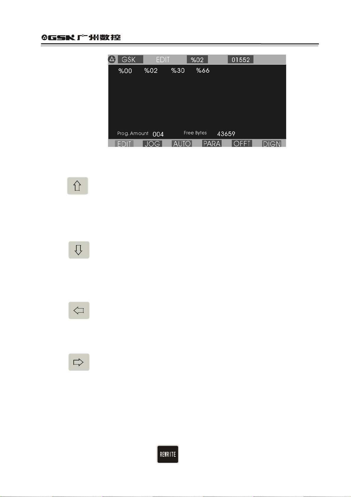
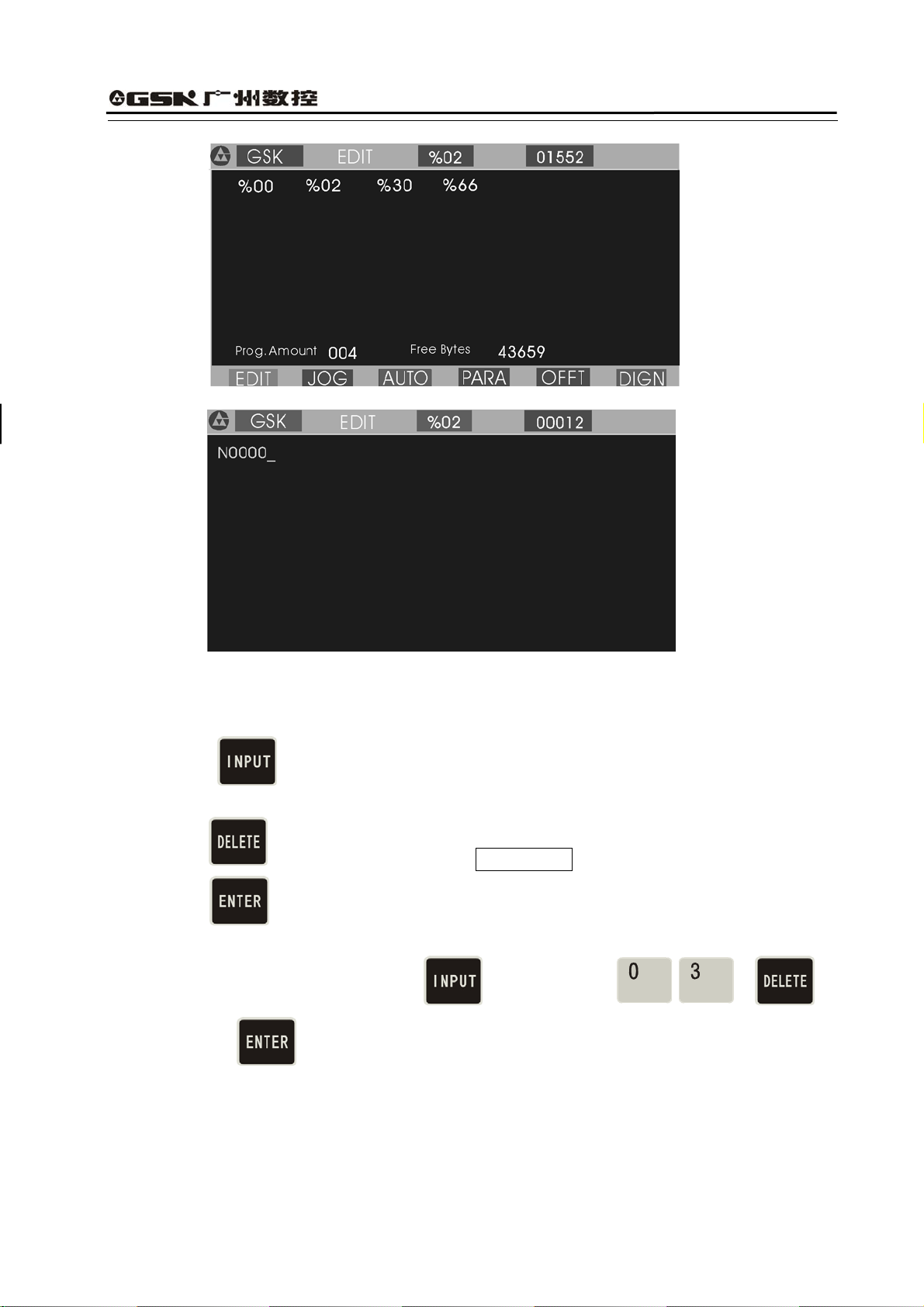
After pressing
to enter EDIT mode, the system displays program names of all part
programs stored in the current program, the byte amount contained in current program and the
available memory bytes of system. See Fig. 2:
15
Page 20
Edit keys in EDIT mode
GSK928TEⅡ Turning CNC System User Manual
Fig. 2 EDIT operating mode
(1)
cursor UP key
The cursor moves to the first character behind the block number of the upper block when the
key is pressed once.
The key being pressed down, the cursor sequentially moves up till the first block of block or
the key is released.
(2)
cursor DOWN key
The cursor moves to the first character behind the block number of the next down block
when the key is pressed once.
The key being pressed down, the cursor sequentially moves down till the last block number
of block or the key is released.
(3)
cursor LEFT key
The cursor moves left one character when the key is pressed once.
The key being pressed down, the cursor sequentially moves left till the first character of
block or the key is released.
(4)
cursor RIGHT key
The cursor moves right one character when the key is pressed.
The key being pressed down, the cursor sequentially moves right till the last character of block
or the key is released.
:
Note
Cursor — prompt identifier to indicate the current editable character position. There are
two states of CNC system.
A. The cursor is displayed to a horizontal line under a character in Insert mode.
B. The cursor is displayed to the pointed character in inverse and highlight. The two
cursors can be switched by
16
.
Page 21
GSK928TEⅡ Turning CNC System User Manual
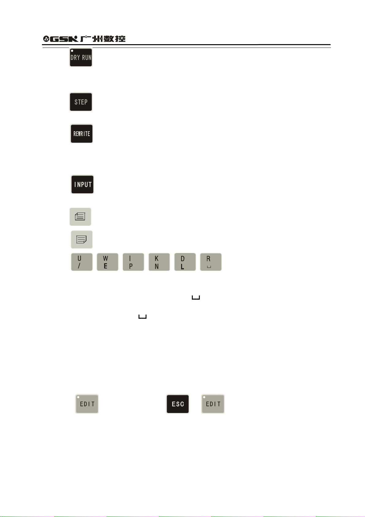
(5) DRY Run key
The cursor moves to the head of block or the head of first word of this block by pressing
continuously.
(6)
STEP/JOG mode
The cursor moves to the behind of the last character of this block.
(7)
REWRITE key
Switch INSERT/REWRITE mode once when the key is pressed once, and the cursor will
change correspondingly. The cursor in Insert mode is a flashing horizontal line, but that in
Rewrite is a character in flashing highlight.
(8)
When the key is pressed once, the program number with 2-digit is input to create a
new program, select or delete the existing program and all programs.
(9) PAGE UP Search the program number and display the content of previous page.
(10) PAGE DOWN Search the program number and display the content of next page.
(11)
Double functions key. Each key has
two definitions. Pressing it once is the first definition value,namely, U W I K D R. The same
key is pressed again, the system will automatically rewrite the previous input value into the
second definition value, namely / E P N L
. If the same key is pressed continuously, the
input value will be switched between the first definition value and the second one. ‘/’ is the
skip block character,‘
’is the space character.
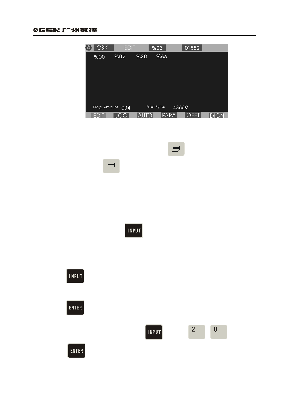
4.3.1 Searching Directory of Part Program
In EDIT mode, the system displays the program name list of all part programs, all part program
amount and the leftover bytes in the part program memory area of CNC system. In EDIT mode,
the system displays the program name list of all part programs, all part program amount and the
leftover bytes in the part program memory area of CNC system.
Press in EDIT mode or press or when editing programs as Fig. 3:
17
Page 22
GSK928TEⅡ Turning CNC System User Manual
Fig. 3 Searching a part program catalog / creating, selecting and deleting part programs
Most %00~%99 program names are displayed in each screen. When part programs in memory
area are over 100, they are displayed by paging. Press
list of next page and press
to display again the program number list of first page till the
to display the program number
last page.
4.3.2 Creating, Selecting, Deleting, Renaming and Copying a Part Program
The above-mentioned operations can be executed in the state of catalog search of part program or
in the course of editing program content.
The system displays as Fig. 4 when
program.
4.3.2.1 Creating a New Part Program
(1) Press
in the state of catalog search of part program.
(2) Input a new program number which does not exist in the program catalog list with 2-digit by
keyboard. See Fig. 4.
is pressed in the state of catalogue search of part
(3) Press
.
(4) After part programs are created, the system will automatically enter EDIT mode.
Example: Creating %20 program: Press to input and press
. So the program has been created to enter EDIT mode of %20 program. See
Fig. 5:
18
Page 23
GSK928TEⅡ Turning CNC System User Manual
Fig. 4 Inputting a program number
Fig. 5 Creating a new part program
4.3.2.2 Deleting a Part Program
(1) Press
in the state of catalog search of part program.
(2) Input the required deleted program number by keyboard.
(3) Press
and the system will display Confirm ?.
(4) Press to delete the part program which program number has been input; press any
keys to cancel the deletion.
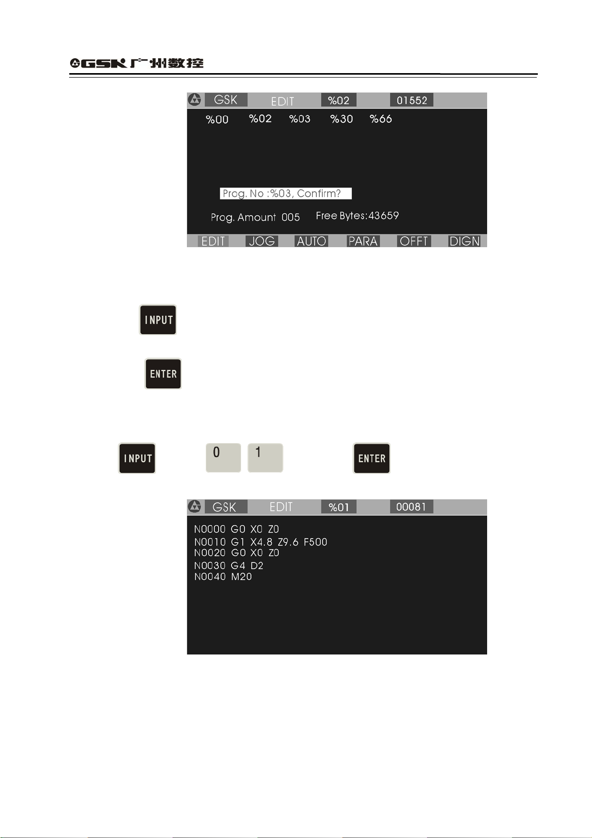
Example: Deleting %03 program: press and then orderly , ,
and
, so the program is deleted as Fig. 6:
19
Page 24
GSK928TEⅡ Turning CNC System User Manual
4.3.2.3 Selecting a Part Program
Fig. 6 Deleting a part program
(1) Press
in the state of catalog search of part program.
(2) Input the required selected program number by keyboard.
(3) Press
.
(4) The part program is selected completely and the system displays its content to enter EDIT
mode.
Example: Selecting %01 part program.
Press
See Fig. 7:
to input and then press , so the selection is completed.
:
Note 1
After the first power on, the system enters EDIT mode or there is no content in the
Fig. 7 Selecting a part program
memory area of part program, it will automatically create and select %00 program. The
system will consider %00 as the current program after it be initialized.
Note 2: After the system has selected one program, the required one is changed only by
selecting it. Even if the system powers off, the selected program number cannot be
changed once it is selected.
20
Page 25
GSK928TEⅡ Turning CNC System User Manual
4.3.2.4 Outputting a Part Program
Output part programs from CNC system internal memory to the external computer.
1. Connect the communication cable between CNC system and the computer when power off.
1. After CNC powers on, select EDIT mode.
2. Select the required part program according to Section Operation, 4.3.2.3 Select a part
program (do not select it if the current program is to be sent).
3. Press
, and the system prompts Ready To Send !.
4. Keep the computer in the state of waiting for the receiving(See appendix: GSKR 232
communication program specification).
5. After the computer is ready, if
is pressed, the system will prompt Sending … , and
so the system sends the selected program to the computer.
6. After the sending has completed, the system prompts Finished ! , and any keys are
pressed to return to EDIT mode.
7. Press
to pause the sending.
4.3.2.5 Inputting a Part Program
Input the stored part program from the external PC to CNC system.
(1) Connect the communication cable between CNC system and the computer when power off.
(2)After CNC system powers on, select EDIT mode.
(3)Press
and the system prompts Ready To receive!.
(4) Keep the computer in the state of output. (See Appendix GSKTR communication
program specification ).
(5) After the system is ready, if
is pressed, the system will prompt Receiving … ,
and so the system sends the selected program to the CNC system.
(6) After the receiving is completed ,the system prompts Finished ! and returns to EDIT
mode if any keys are pressed. The system displays the input program name in the catalog
list of part program.
(7) Press
to interrupt the receiving.
Note 1: In the course of inputting part program, CNC system considers the character string “%
XX” contained in the first block of the sent program from the computer as the program
21
Page 26
GSK928TEⅡ Turning CNC System User Manual
name to save. If the sent program name is the same as one in CNC system, the system
cannot display the program name content of the sent program name, and will display it if
the old one is deleted.
Note 2: Send/receive part programs between 2 GSK928TE
Ⅱ
CNC systems according to the
above–mentioned methods. 2 CNC systems separately operate according to part
program input/output ways.
Note 3: It must have the block number of part program when the part program is sent from PC to
CNC system, otherwise there is a mistake.
4.3.2.6 Deleting All Part Programs
Delete all programs once in the program memory area of CNC system.
Press
Input ⑵
Press⑶
in the state of catalog search of part program.
, by keyboard.
,and the system prompts Confirm ?
Press⑷ to delete all part programs. Press other keys, and the system does not execute
the deletion and returns to EDIT mode.
Note: Press and then , release and then to delete all part program.
4.3.2.7 Renaming a Part Program
Rewrite the current program name to another one.
Press ⑴
, and the system displays % .
Input the program name which does not exist in the program name list, and press ⑵
to rewrite the current program name to the input program name.
Example: Rename the current program name %00 to % 05.
Press
to input , and press , so the renaming is
completed.
22
Page 27
GSK928TEⅡ Turning CNC System User Manual
4.3.2.8 Copying a Part Program
Copy the content of current program to another new one and consider it as the current one.
Press⑴
, and the system displays % .
In⑵ put a program name which does not exist in the program name list, and press to
copy all contents of current program to the program whose number is input.
The new program name becomes the current one.
Example: Copy program of current program name % 00 to that of %05.
Press
to input , and press , so the copy is completed.
Note: If the input program name exists, the system will prompt File Existed . At the moment,
press any keys to input again the program name which does not exist in the program area,
and then press
, So the copy is completed.
4.3.3 Inputting/Editing Content of Part Program
CNC machining is defined that the system automatically completes the machining of workpiece
according to the part program sequence input by user. Each program is composed of many
blocks and each block consists of a block number, codes and data. Start the machine and gain
the standard workpiece after inputting the part program content according to the technology flow.
EDIT mode of CNC system uses the full-screen and part programs are employed with the file
management mode.
4.3.3.1 Automatically Creating a Block Number
Each part program contains many blocks and each block begins with the block number“ N**** ”;
After a new program is created, the system will automatically generate the first block
number“ N0000 ”; After one block is input and
is pressed, the system will generate the
next block number. In the course of input, the increment of block number is defined by P23.
When a block is inserted, the system will automatically consider the 1/4 integer value of P23 as
the increment to generate the block number. When M98, M97, M91, M92, M93, M94 and others
codes related with the block number are executed, there are no repetitive block numbers in the
program, otherwise the system will alarm. If the above codes are not executed, the block number
can be repeated.
See Fig. 8 for a program generation and inserting a block number in a block (P23 value is 10).
23
Page 28
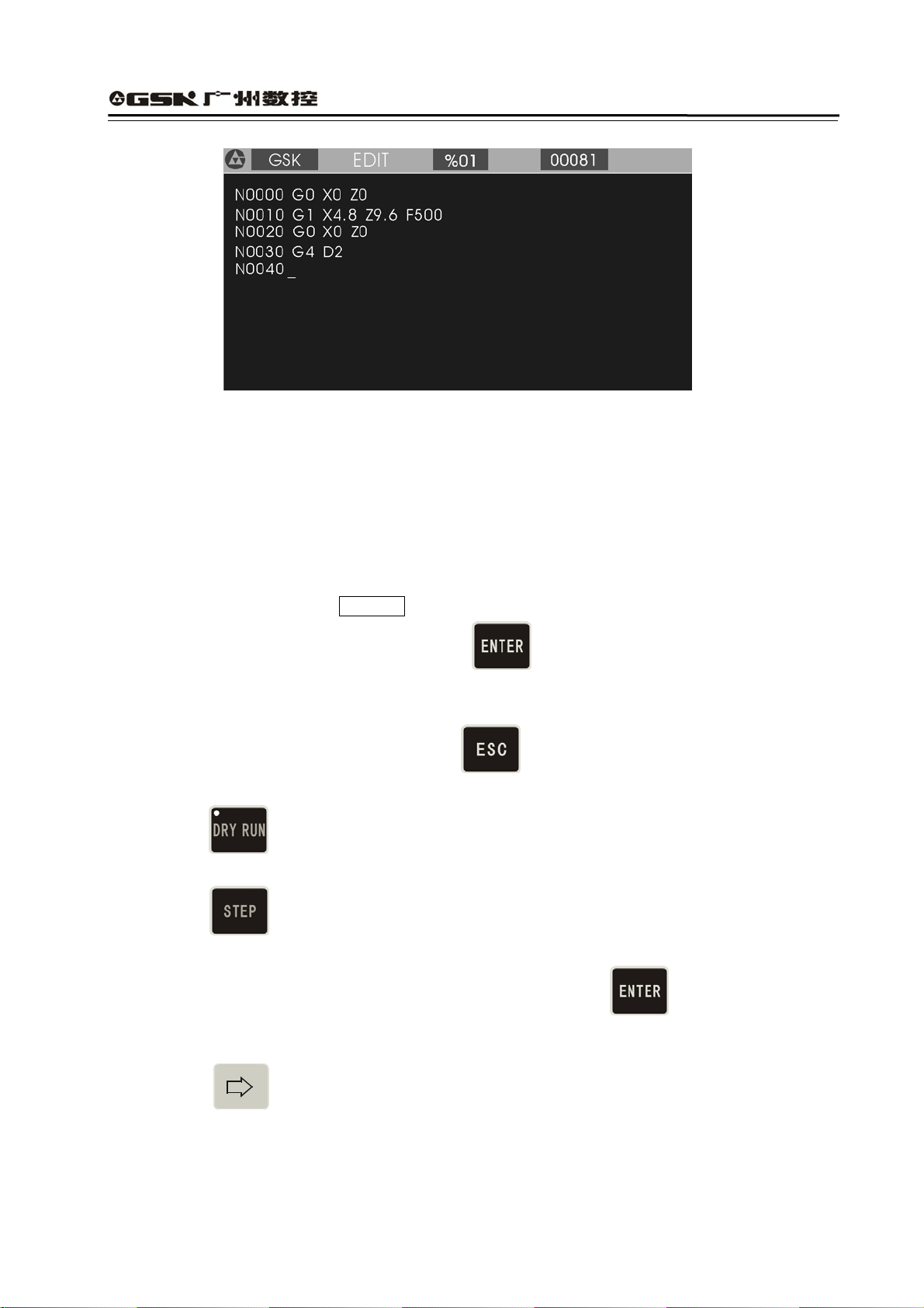
GSK928TEⅡ Turning CNC System User Manual
Fig. 8 automatically creating block number and inputting program content
4.3.3.2 Inputting Content of Program
EDIT mode of the CNC system is employed with the full screen. Inputting content of program is
executed in EDIT mode.
(1) Create a new program according to the creating method of new part program.
(2) After the block number N0000 is displayed, input the content of one block by keyboard.
(3) Input completely one block and then press .
(4) The system will generate the sequence number of next block and the content of program
should be input continuously.
(5) Input completely the last block and press
to end the input of content of program.
(6) The cursor rapidly moves in the block.
Press
once, and the cursor will point to the head of word; press it again,and the
cursor points to the head of block, and the above steps are executed circularly.
Press
once, the cursor points to the end of block.
(7) Insert a block in the first block.
Move the cursor to the head of the first block and then press .
Note: There are 255 characters at most in one block. When the characters exceed the screen,
pressing
displays one character left.
4.3.3.3 Inserting a Block
Insert one or more blocks between two blocks.
24
Page 29
GSK928TEⅡ Turning CNC System User Manual
(1) Press to move the cursor to the first one of two blocks.
(2) Press
to move the cursor to the behind of last character, or press to move
directly the cursor to the behind of last character.
(3) Press , and the system will generate a new block number between two blocks (the
increment of sequence number is 1/4 integral value of P23, and if there is not enough, the
block number of the next block is rewritten.) and blank one block.
(4) Input the content of required block.
(5) After the content is input,
is pressed to insert blocks. When only one block is inserted,
the operation is not executed.
(6) The inserting is completed.
(7) If the block is inserted before the first block,
is pressed to move the cursor to the
under “N” of the first block, and the system will generate a new block number before the first
block after is pressed.
Note
:
After one block is inserted behind the last block and is pressed, the system will
automatically generate the next block number.
Example:Insert a new block M3 between N0020 and N0030 in Fig. 8 as follows:
(1) Press to move the cursor to N0020 , and press to move the
cursor to the behind of Z0.0.
(2) Press
, and the system will automatically generate one block number and blank a
block to display N0022 as Fig. 9. The cursor points to the first input character of the new
block.
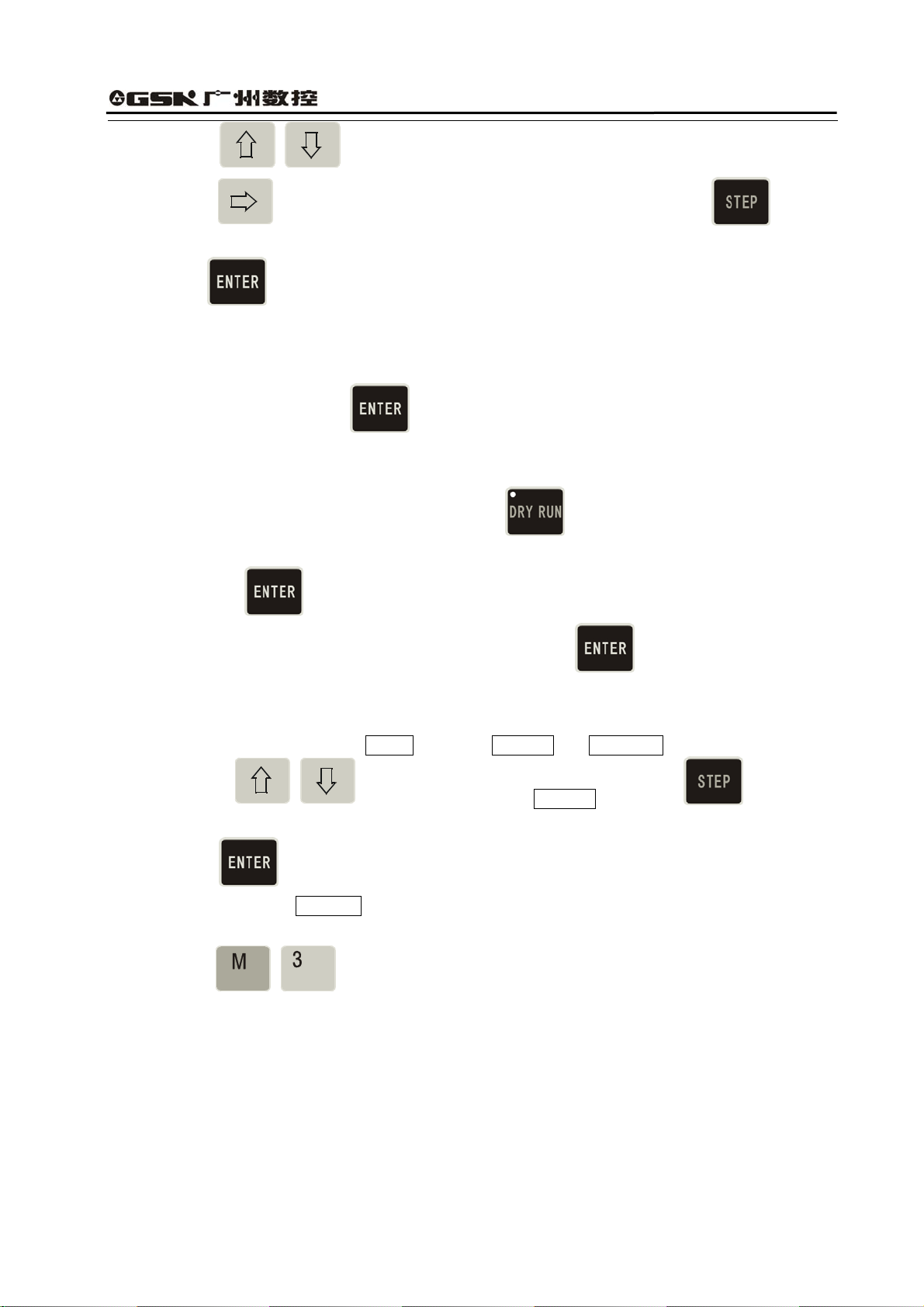
(3) Input
.
(4) The inserting is completed as Fig. 10.
25
Page 30
GSK928TEⅡ Turning CNC System User Manual
Fig 9. Generating a new block number after
Fig. 10 Input and end the insertion
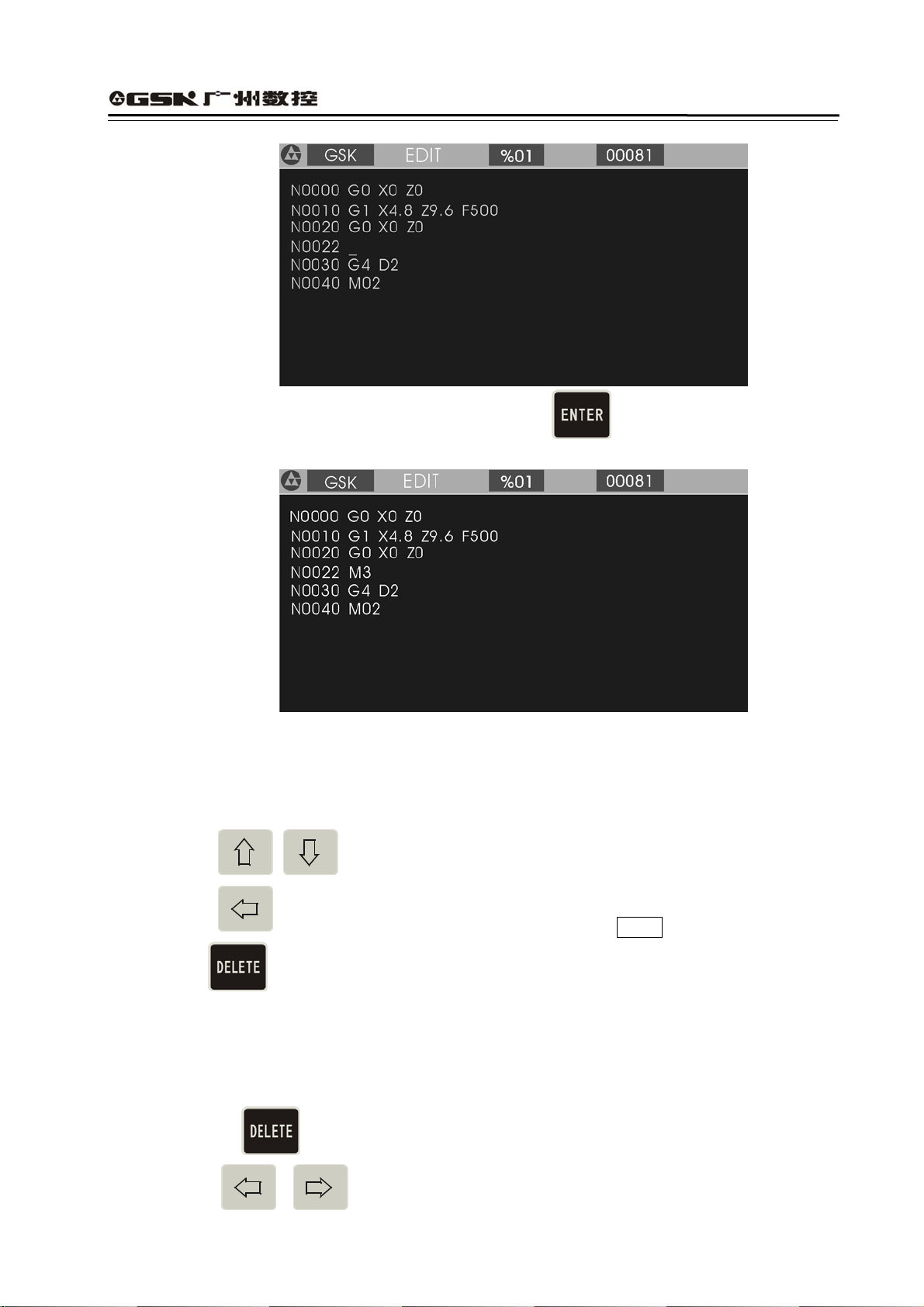
4.3.3.4 Deleting a Block
Delete all content in one block (including block number).
(1) Press
to move the cursor to the required block.
is pressed
(2) Press
to move the cursor to the under of the address N of required block.
(3) Press .
(4) Delete all content of the selected blocks.
4.3.3.5 Inserting a Word in a Block
(1) Ensure the current input operation is in Insert mode, i.e. the cursor displays to the under of
block. If
(2) Press
26
is not pressed, switch Input to Insert mode.
or to move the cursor to the address character behind the required
Page 31

GSK928TEⅡ Turning CNC System User Manual
inserting position.
(3) Input the inserting content.
(4) Insert the content before the address character pointed by the cursor.
Example:Insert 1 between X and 0 of N0020 G0 X0.0 Z0.0. Move the cursor to
the under of O behind of X ,and input 1 . N0020 G0 X10.0 Z0.0 is displayed.
:
Note
The system requires there is a space between each word (a letter adding the following
digits) in block. The system can automatically judge and generate a space in the course
of inputting when the program is edit, but cannot automatically judge in the course of
inserting, and so the user will input the space to ensure the complete program.
4.3.3.6 Deleting a Word in a Block
Delete the invalid content.
(1) Press to move the cursor to the required address character.
(2) Press
to delete the address character.
4.3.3.7 Modifying a Word in a Block
Adopt two methods to modify an address character of block according to the input mode
(INSERT/REWRITE).
INSERT mode: use the insert and the delete methods together.
(1) Press
,move the cursor to the required address character.
(2) Input the new word.
(3) Delete the invalid word according to the operation of deleting the content of block.
REWRITE mode: modify the character where the cursor points.
(1) Press
to switch to REWRITE mode (the cursor pointing to the address character in
highlight square).
(2) Press
to the required address character.
(3) Input the new address character, and the cursor points to the next one.
Example:Rewrite X of N0020 G0 X0.0 Z0.0 to U .
(1) Switch to Rewrite mode.
(2) Move the cursor to the under of X .
(3) Input U .
27
Page 32

GSK928TEⅡ Turning CNC System User Manual
The end is :N0020 G0 U 0.0 Z0.0.
4.3.3.8 Skipping a Block
Add / before the block number N of block, and the system will skip the block to execute
the next one when executing the program.
(1) Switch to INSERT mode.
(2) Move the cursor to the required block and press
the block number N of block.
(3) Sequentially press two times: the first time, insert before N ; the second
time, insert / before N .
to move the cursor to the under of
4.4 Manual Mode
In “Manual” mode, the motion of slider, the starting/stopping of spindle, cooling ON/OFF, manual tool
change, the program reference point return and the machine zero return in X, Z direction, and other
functions can be completed by operating the keyboard. When P11 Bit3 is set to 1, the actual spindle
speed can be displayed real time; when P11 Bit3 is set to 0, the programming spindle speed is
displayed. When the machine is equipped with the hydraulic chuck and the tailstock, the system can
control the operation of the hydraulic chuck and the tailstock by a pedal switch or external keys. They
keep interlock between the hydraulic chuck, the tailstock and the spindle.
Press
to enter Manual mode. There are JOG Jog mode and JOG Step mode. The initial
mode is JOG. Press to switch between JOG mode and Step mode. If the system is equipped
with the MPG, the system can adopt MPG control mode. JOG mode. is as follows:
Fig.11 JOG mode
4.4.1 Manual JOG
In JOG mode, press down a manual feed direction key, and the slider will continuously
28
Page 33

GSK928TEⅡ Turning CNC System User Manual
traverse along the selected axis and direction. The slider will stop once the key is released.
The traverse speed will be executed according to the selected rapid traverse speed or feedrate.
Meanings of manual feed direction keys in JOG mode are as follows:
X negative key
X positive key
Z negative key
Z positive key
Note 1: Press the feed key in JOG mode, and the slider will traverse when the external spindle
and the feed hold knob are permitted to feed; press the manual feed key, and the
slider does not traverse in the state of feed hold.
Note 2: Even though the feed key is released, because the system automatically
accelerates/decelerates, the slide will continuously traverse not to stop when the
motor runs rapidly. The actual moving distance is determined by max. speed of the
motor, the acceleration/deceleration time and the feedrate override. The more the
acceleration /deceleration time is and the rapider the speed is, the longer the moving
distance of motor decelerating is, otherwise the moving distance is shorter.
4.4.2 Manual(JOG) Step
In STEP mode, the moving distance of slider each time is preset. The slider will traverse one
setting step in the selected coordinate axis and its direction when the manual feed direction key
is pressed once. When the key is pressed down, the slider feeds as one step until the last step
after it is released. The step width value is displayed with black.
Manual Step feed mode as Fig. 12:
Fig. 12 Manual step feed mode
29
Page 34

GSK928TEⅡ Turning CNC System User Manual
Its step width is divided into 6 grades: 0.001 0.01 0.1 1.0 10.0 50.0
Press
to select each step width. The step width degrades one grade if it is pressed once. It
returns to the first grade after the last one is selected.
Note 1: In STEP mode, press
to stop slider traversing. When the key is pressed down,
the slider stops and the unfinished step will not be reserved, and then the feed key is
pressed to execute the next step feed. X step width is the moving distance in diameter.
Note 2: When the manual feed key is pressed, the external spindle and the feed hold knob are
permitted to feed, the slider traverses. When the manual step feed key is pressed, the
slider does not traverse in the state of feed hold.
Note 3: When the slider is traversing and the feed hold knob rotates to the feed hold position,
the slider will decelerate to stop and the unfinished step width will not be reserved.
4.4.3 Manual MPG (Handwheel) Control
In MPG mode, the micro motion of slider is controlled by rotating the manual pulse generator
(MPG). Press
or to enter MPG mode and select the coordinate axis controlled by
the MPG at the same time. See Fig. 13 (taking X axis as example).
Fig. 13 MPG control
z Rotate the MPG after selecting the required coordinate axis to move. The selected axis will
move along with the MPG rotating.
The MPG rotates (CW), the axis moves positively.
The MPG rotates (CCW), the axis moves negatively.
z There are three gears for each motion amount of MPG: 0.001, 0.01, 0.1mm. Press
to switch among them. The system will automatically select 0.1 mm when the previous step
size exceeds 0.1 from STEP mode to MPG mode.
z The system does not display the current speed of the spindle in MPG mode.
30
Page 35

GSK928TEⅡ Turning CNC System User Manual
Note 1: The MPG speed of should be lower than 5 rev/s, otherwise the motor still moves even if
the MPG has stopped, which causes the moving distance does not correspond with the
scale.
Note 2: In MPG mode, all the functions related to the axis moving including JOG, zero return,
incremental/absolute movement are invalid, but S, M, T and other auxiliary functions
are valid.
Note 3: Even if the MPG is shaken, the slider does not traverse when the external spindle and
the feed hold knob forbid the slider to traverse. The spindle speed cannot be changed
real time.
Note 4: When the bigger override (X 100) is selected, the motor will rapidly traverse if the MPG
is rotated rapidly. At the moment, because the system automatically accelerates/
decelerate, the motor will traverse not to stop although the MPG stops. The actual
moving distance is determined by max. speed of motor, the acceleration/ deceleration
time, the feedrate override and the MPG speed. The rapider the speed is, the longer the
acceleration/deceleration time is and the rapider the MPG speed is, the longer the
moving distance of motor decelerating is, otherwise the shorter the moving distance of
motor is.
4.4.4 Manual Feedrate
Select the feedrate override in JOG feed mode.
The feedrate override increases one gear by pressing it once. Max. value :150%.
The feedrate override degrades one gear by pressing it once. Min. value : 0%.
Note 1: In JOG or MPG feed mode, select the feedrate override and then traverse the axis by
pressing manual feed direction key or rotating the MPG.
Note 2: In Step feed mode, select the feedrate override or increase/decrease the feedrate
override in the course of moving to change the feedrate.
Feedrate override (16 gears) as follows:
Feed override
0 0
10 7.5
20 22
30 38
40 60
50 82
60 110
70 180
80 240
90 300
100 420
110 525
31
Feedrate(mm/ min )
Page 36

GSK928TEⅡ Turning CNC System User Manual
120 675
130 850
140 1000
150 1260
4.4.5 Manual Rapid Traverse Speed/Feedrate
Select the rapid traverse speed/feedrate in JOG feed mode. The rapid traverse speed can be
selected by rapid traverse override divided into four gears 25%, 50%, 75%, 100%.
The actual feedrate is defined by the rapid traverse speed and the rapid traverse override:
X actual rapid traverse speed = P06 ×rapid traverse override
Z actual rapid traverse speed = P05 ×rapid traverse override
Selecting the manual rapid feed and the rapid traverse override is as follows:
Press
and rapid traverse override is displayed in a highlight square. Press
manual feed mode. See Fig. 14 for manual rapid traverse mode:
Switch feed/ rapid traverse.
Increase one gear of rapid traverse speed by pressing it once (Max. 100%).
Reduce one gear of rapid traverse speed by pressing it once (Min. 25%).
to switch to manual rapid traverse with the indicator ON. The feedrate override
again to switch to
Fig. 14 Manual rapid traverse
Note 1: In JOG feed mode, select the rapid traverse override and then press the coordinate axis
feed key.
Note 2: In Step feed mode, select the rapid traverse override or increase/reduce the rapid traverse
override in the course of traversing to change the rapid traverse speed.
32
Page 37

GSK928TEⅡ Turning CNC System User Manual
4.4.6 Creating a Workpiece Coordinate
GSK928TE CNC system Ⅱ uses a floating workpiece coordinate which is the benchmark of
toolsetting and related dimension. After the system is installed, the workpiece coordinate must be
created firstly. When the actual position is inconsistent with that of the workpiece coordinate, the
coordinate is created again as follows:
(1) Install the trial workpiece reliably on the machine, and select a tool (usually select the first
one used in machining).
Select the proper spindle speed, and then start the spindle. Traverse the tool in “Manual”
mode, and cut a small sidestep of the workpiece.
X does not move but Z does to the safe position, and stop the spindle.
Measure the diameter of the cut sidestep. Press
to display Setting , and then
press to display Setting X, at last, input the metrical diameter and press ,
so the system creates automatically X workpiece coordinate, if is pressed , the
system cancels the creation of X workpiece coordinate.
(2) Start the spindle again and traverse the tool to cut a face on the workpiece in “Manual”
mode.
(3) Do not move Z but X to the safe position, and stop the spindle.
Select a datum mark (it is a fixed point on the machine, such as the face of chuck, the datum
plane of fixture, which can ensure the created new workpiece coordinate system coincides
with the previous broken one). Measure Z distance from the cut end face to the datum mark.
Press
to display Setting and press to display Setting Z , at last, input
the metrical diameter and press , the system creates automatically Z workpiece
coordinate, if
coordinate.
is pressed , the system cancels the creation of Z workpiece
Clear out the previous system offset after the workpiece coordinate system has been
created as the above-mentioned operation. If the workpiece coordinate system is not
created, there is warp between the current X, Z coordinate values displayed and the actual
tool position. Initialize the system before creating the workpiece coordinate system.
4.4.7 Setting Program Reference Point
The program reference point can be any position on the machine. Once the program reference
point is created, the slider anywhere else will return to this point by executing the program
33
Page 38

GSK928TEⅡ Turning CNC System User Manual
reference point return (G26, G27, G29) or pressing the reference point return keys, at the
moment, cancel the tool compensation and the system offset. There are two methods to modify
the tool offset values(absolute input and incremental input) as follows:
The first method:
Move the cursor to the required tool offset number, press
to display Setting, and then
press to display Program Reference Point ?, at the moment, the point is the program
reference point by pressing . Cancel the setting of reference point by pressing .
There is no responding by pressing other keys.
The second method:
move the cursor to the required tool offset number, directly input the tool offset value and press
to complete the tool offset modification.
After the program reference point set, the previous reference point coordinate values do not be
changed in the new one if the workpiece coordinate is created again, and at the moment, the
program reference point needs to be set again. The initial value of program reference point is
X=150, Z=150.
4.4.8 Incremental Movement of Coordinate Axis
In “Manual” mode, traverse one axis according to the distance and direction input by user instead
of the step size defined by the system. Operations are as follows:
(1) Select the required axis to traverse. Press
displays Move U; press
to traverse Z, the system displays Move W.
to traverse X axis, and the system
(2) Input the required actual moving distance by keyboard. Input X, Z values with negative sign.
X value is in diameter. Press
to delete the wrong input. Press to cancel
the input and return to “Manual” mode.
(3) After inputting the data, press
, and the system displays “Run ?”; press
to traverse the selected axis according to the input distance and the direction.
Press
to cancel the movement and return to “Manual” mode.
(4) The incremental speed is the current selected manual speed.
34
Page 39

GSK928TEⅡ Turning CNC System User Manual
Example:X moves negatively 15.8 mm from the current position as follows:
Press U – 1 5 . 8
, and the system displays Run ?; press , and
X moves negatively 15.8 mm.
4.4.9 Absolute Movement of Coordinate Axis
In “Manual” mode, traverse directly one axis from the current position to the input coordinate
position. Operations are as follows:
1. Select the required axis. Press
to move X axis, and the system displays Move X ; press
to move Z axis, the system displays Move Z.
2. Input the required actual coordinate value to reach the position (X value is in diameter) by
keyboard, and press
to delete the wrong input. Press to cancel the input and
return to “Manual” mode.
3. After inputting the data, press , the system automatically counts the required moving
distance and direction. With Run ?on the screen, press to move to the input coordinate
position. Press to stop and return to “Manual” mode.
4. The absolute speed is the current defined manual speed.
Example: Modify it into 85 if Z coordinate value is 50.
Press Z 8 5 and , the system displays Run ?, and the coordinate is
modified into 85 by pressing .
Note: In “Manual” mode, only one axis can be executed the incremental or absolute movement
at the current selected manual speed
.
4.4.10 MDI Function
In “Manual” mode, M functions can be executed by inputting M codes. Press
to display M,
and then input one or two-digit and press to execute the corresponding M function, or
press
to cancel the execution of M function.
Press ‘M’, ‘0’, ‘3’ to start the spindle rotating (CCW). Input and execute the following M codes:
35
Page 40

GSK928TEⅡ Turning CNC System User Manual
M03 M04 M05 M08 M09 M10 M11 M32 M33 M21 M22 M23 M24. Omit it if
the first digit of M code is zero. The function is the same that in AUTO mode. For the explanations
of M codes, see Programming.
When MDI is error, the system prompts “DATA INVALID” and disappears by pressing
MDI mode, when the data is input or the coordinate is set,
instead of is
pressed, the system prompts “DATA INVALID” to escape. For example: input orderly T22 and
press , the system prompts “DATA INVALID” and escapes.
4.4.11 Manual Spindle Control
In “Manual” mode, the rotation (CCW/CW) and stop of spindle can be controlled by the keyboard
(if the feed/spindle hold knob is set in the position where the spindle is forbidden to rotate, the
spindle cannot be started even if the spindle rotation (CCW/CW) key is pressed. See User
Manual from the machine manufacture for gears of feed hold knob and mark symbols, and
Connection in the manual if the spindle needs to be connected separately).
Spindle rotation (CCW)
Displaying:SPINDLE CCW and LED ON
. In
Spindle stop
Displaying:SPINDLE STOP and LED OFF
Spindle rotation (CW)
Displaying:SPINDLE CW and LED ON
Note: Whether its brake signal is output is defined by MSP bit of P12 when the spindle stops. If
P12 MSP is 1, there is the brake signal when the spindle stops. If MSP is 0, there is
nothing. The time sequence relationships of the spindle brake, starting and stopping
signal are as follows:
1) In pulse control mode,M3, M4, M5, MSP output time sequence:
M3 or M4
M5
MSP
T1
T1
T2
T3
36
Page 41

GSK928TEⅡ Turning CNC System User Manual
2) In level control mode,M3, M4, M5, MSP output time sequence
M3 or M4
M5
T1
T2
MSP
T3
T1:In pulse control mode,M3, M4, M5 signal duration is set by P15;
T2:Setting value: 0.2s;
T3:The output duration of spindle braking signal MSP is set by P16.
4.4.12 Manual Spindle Speed Control
For the machine with the multi-gear motor, press
to control the speed in JOG mode.
(1) Mechanical gear shifting control
When the P12 bit 0=0 (spindle speed controlled by the mechanical gear shifting), the output
mode of gear signal with multi-gear control is selected by P11 Bit4. When P12 bit 0=1, P11
Bit4 is invalid.
P11 Bit4=0: the gear signal is directly output for each bit. Each gear signal corresponds to an
output point from S0 to S4. S0 means that all output is invalid.
P11 Bit4=1: the gear signal is output according to the code. At the moment, the specific
spindle speed is gained from S00 to S15 by the external power circuit decode as
follows:
Code
Output point
S00 S01 S02 S03 S04 S05 S06 S07 S08 S09 S10 S11 S12 S13 S14 S15
or directly input the spindle speed code
S1 ★ ★ ★ ★ ★ ★ ★ ★
S2 ★ ★ ★ ★ ★ ★ ★ ★
S3 ★ ★ ★ ★ ★ ★ ★ ★
S4 ★ ★ ★ ★ ★ ★ ★ ★
“ ” means the output of corresponding output point is invalid.★
Spindle speed control operation:
Input S codes by keyboard to control the spindle speed. Pressing“ S” inputs the required speed
code; press
, and the system outputs the control signal according to the selected S code
mode.
Example: Select the eighth gear spindle speed.
37
Page 42

GSK928TEⅡ Turning CNC System User Manual
Input orderly S 8
, and S8 signal is output with the displaying Prg. Speed S08.
Besides, press to change the spindle speed. If it is pressed once, the spindle speed is
output circularly S1, S2, S3, S4,(P11 bit 4=0) or S0~S15 ((P11 bit 4=1). The spindle speed
switches from S2 to S1 by pressing
three times when the spindle speed only has
two-gear.
(2) Frequency conversion control:
Select the converter to control the spindle speed when P12 Bit =1. Directly input the speed to
control the spindle when the machine is equipped with the converter to control the spindle.
Press
key to display S and input the required speed, then press , the system
converts the speed to 0-0V analog voltage by the output interface to output to the converter.
z To settle problems of the converter with low speed and torque, the system can execute
automatically the three-gear output signal, matching with the converter to ensure the
machine gain the low speed and power torque under the high frequency.
The system
provides three codes: M41, M42, M43 and three parameters: P09, P10, P24.
P09: Reach max. speed when the reduction gear of spindle is positioned on the low gear.
P10: Reach max. speed when the reduction gear of spindle is positioned on the high gear.
P24: Reach max. speed when the reduction gear of spindle is positioned on the medium gear.
M41: Output the low gear signal and use max. speed set by P09.
M42: Output the medium gear signal and use max. speed set by P24.
M43: Output the high gear signal and use max. speed set by P10.
Use M41, M42, M43 to select the required gear of spindle and then input directly the required
speed, and the system will automatically convert the output voltage to control the speed of
converter according to the current position of reduction gear. After power on, the system will
fault M43, i.e. the spindle is positioned on the high gear.
z Display the spindle speed: when P11 Bit 3=0, the programmed spindle speed is displayed
on the screen. When P11 Bit 3=1, the actual spindle speed is displayed.
z Detecting the encoder lines of spindle: the system directly detects the pulse amount per rev
of spindle encoder in “Manual” mode as follows:
Start the spindle and press
, and the system displays the pulse amount per rev of
spindle encoder. The system will prompt Encoder Error if the spindle is not started or the
encoder does not be installed. Press any keys to end the detection and return to “Manual”
mode.
38
Page 43

GSK928TEⅡ Turning CNC System User Manual
Note 1: The spindle speed is controlled by P12 Bit0. When Bit0=0: it is the multi-gear control; when
Bit0=1: it is 0-10V analog voltage control.
Note 2: When P12 Bit0=1, P11 Bit4 is invalid, i.e. the spindle is always controlled by the converter. At
the moment, the output point S1, S2, S3, S4 is controlled by M41, M42, M43, and the
corresponding output point cannot be controlled by the spindle gear shifting key.
4.4.13 Manual Cooling Control
In “ Manual “ mode, press the key to control the cooling ON/OFF.
Cooling ON/OFF
Press
to switch the cooling ON/OFF. Start the cooling, and the system displays the
cooling is ON and LED is ON; stop the cooling, and the system displays the cooling OFF
and LED OFF.
4.4.14 Manual Tool Change Control
This system can control the tool post with 4 tool selections. It also can be extended to 8 tool
selections when T5~T8 tool selection signals are input in code mode. Three kinds of tool
change methods are as follows:
● Set P12 Bit1 to 0 and press
once, and the tool post rotates to the next controllable tool
number and the system displays the corresponding one.
● Set P12 Bit1 to 1, press once and , and the tool post rotates to the next
controllable tool number and the system displays the corresponding controllable tool number. If
is pressed, the tool post cannot execute the tool change when other keys are pressed.
● Input T * O directly by keyboard (* standing for rotating to the required controllable tool number)
and then press , and the tool post rotates to * which is pointing to the controllable tool,
and 0 stands for canceling the tool offset.
Note 1: For the first two methods, do not execute the tool compensation but the tool change, but
for the third, execute the corresponding tool compensation after inputting the tool
compensation number behind * .
39
Page 44

GSK928TEⅡ Turning CNC System User Manual
Example: Input T22: switching to No. 2 tool and executing its compensation.
Input T31: switching to No. 3 tool and executing its compensation.
Input T40: switching to No. 4 tool and executing its compensation.
Input T00: canceling the tool change and the tool compensation.
Note 2: If the rotation tool post is failure, the system displays Tool NO. Lost , which indicates that
the system has not found the corresponding tool number in the specified time.
Note 3: The system is employed with the absolute tool change. When adopting the rotation tool
post, the tool number is fixed on the tool post. It ensures the tool number on the tool post
is the same as the one displayed on the screen.
Note 4: When P11 Bit5 is 1, select the line-up tool post. There is no signal output when executing
the tool change.
Note 5: When using the third method, execute the tool compensation by traversing the slider or
modifying the system coordinate which is defined by P11 Bit6.
Bit6=0: do not modify the coordinate but traverse the slider to execute the tool
compensation.
Bit6=1: do not traverse the slider but modify the coordinate to execute the tool
compensation.
4.4.15 Manual Toolsetting Operations
Usually, several tools are used in the course of machining a workpiece. Owing to the installation
and tool offset, the cutting position to which each tool rotates cannot coincide with that of the tool
nose. To avoid the tool offset in programming, this system set the automatic toolsettig method
according to the tool offset. User does not consider the tool offset but edits the part program
according to the workpiece drawing and the cutting technology, and calls the corresponding tool
compensation in the tool change command during the course of machining (For the usage, see
Program, tool compensation function).
Here are the two methods in this system:
GSK928TE CNC system has set the trial cutting and the fixed point toolsetting, and user can Ⅱ
select anyone. The specifications are as follows:
Trial cutting toolsetting mode:
(Create the workpiece coordinate system before adopting the trial cutting toolsetting mode. The
operations are the same those of ones after setting the workpiece coordinate system or
executing the program reference point return〔program home return〕)
1. Prepare for the toolsetting.
2. Input T00 to cancel the previous tool offset and then execute the toolsetting when the tool
offset number is not zero,otherwise the system will count all values between the previous tool
offset value and the new one (the operations must be executed when the tool is worn and
needed to execute the toolsetting again). If necessary, execute the toolsetting with the tool
40
Page 45

GSK928TEⅡ Turning CNC System User Manual
offset.
3. Select any one tool after the workpiece is fixed on the machine (usually, the tool is the first one
used in machining).
4. Start the spindle with the proper speed. Traverse the tool to cut a little sidestep on the
workpiece in “Manual” mode.
5. X does not move but Z does to the safe position, and stop the spindle.
6. Measure the diameter of sidestep cut. Press
to display Offset X and input the
metrical diameter, and then press to display T * X (* standing for the current
controllable tool number) and press to count X tool offset value and store the value to
X tool offset parameter area to which * corresponds. The offset value can be searched and
modified in OFFSET mode. When T * X is displayed on the screen, input the digit 1~8 and
press to count the tool offset value and store it to X tool offset parameter area to
which the input digit corresponds. Press not
but to cancel the count and the
storage of tool offset.
7. Start the spindle again and traverse the tool to cut a face in “Manual” mode.
8. Z does not move but X does to the safe position, and stop the spindle. Select a point as a
datum mark (usually, the datum mark is a fixed point such as the chuck face, the fixture
datum plane, which is contributed to find easily the previous datum mark when executing the
toolsetting again), and measure X distance from the cut face to the selected datum mark.
Press
to display Offset Z and input the metrical data, and then press to
display T * Z(* standing for the current tool position No.), and last press to count Z
tool offset value and store it to Z tool offset parameter area to which * corresponds. The offset
value can be searched and modified in OFFSET mode. When T *Z is displayed on the
screen, input the number 1~8 and press to count the tool offset value and store it to
Z s tool offset parameter area to which the input number corresponds. Press not
but
to cancel the count and the storage.
9. Change another tool and repeat the above-mentioned operations 1-6 to execute other
toolsetting.
10. If the workpiece coordinate system has not been changed, all toolsettings are executed like
the above-mentioned. The toolsetting is easy and convenient when the tool is worn or
41
Page 46

GSK928TEⅡ Turning CNC System User Manual
needed to tune. Firstly, cancel the tool compensation (T00) or execute program reference
point return (program home) when the tool compensation cannot be input or the counting
data is wrong.
Fixed point toolsetting mode:
1. Select anyone tool (usually it is the first one used in machining) as a reference tool after
installing the trial cutting workpiece on the machine.
2. Start the spindle with the proper speed.
3. Select the proper manual feedrate, traverse the tool to the specified toolsetting point on the
workpiece in the manual feed mode, and stop the movement when the tool coincides with
the toolsetting point.
4. Press
highlight, then press continuously
, and the system display the current tool number and tool offset number in
two times, and the system displays normally the
current tool number and tool offset number, and automatically records the current coordinate
and considers it as the toolsetting reference of other tools (the operation cannot executed if
it is not the reference tool). It is necessary to execute the following operation for the
reference tool.
5. Press
and then (if the tool wears, press to execute the toolsetting
by taking the executed toolsetting tool as a reference), and the system displays normally the
current tool number and tool offset number, counts the offset value of the current
corresponding tool number and stores it to the corresponding parameter area. The offset
value can be searched and modified in OFFSET mode.
6. Traverse the tool to the tool change position from the toolsetting position in “Manual” mode
and rotate the next required one to the cutting position by manual tool change.
7. Repeat the above-mentioned operations 2, 3, 5 until all toolsettings have been completed.
Note 1: When adopting the optic toolsetting instrument, do not start the spindle but fix the
toolsetting point on the cross point of the toolsetting instrument, other operations are
the same as the above-mentioned.
Note 2: The tool offset automatically created by the system can be displayed and modified in
OFFSET mode. See OPERATION, OFFSET mode.
Note 3: If the tool is worn to change or a new one is installed, select another one which has been
executed the toolsetting as the reference tool. Firstly, fix the tool to the selected point on
the workpiece according to the toolsetting of reference tool (as the above-mentioned
operation No. 4 instead of No. 5), then, return to the safe position, last, change the new
tool and repeat the above No. 2, 3, 5 step to execute the toolsetting (the previous offset
value is not always zero).
Note 4: When the line-up tool post toolsetting is used and the tool is on the other side of
workpiece, X input metrical value is negative in the course of trial cutting toolsetting.
42
Page 47

GSK928TEⅡ Turning CNC System User Manual
When the fixed point toolsetting is executed by hand, X tool offset value sign related to
the tool number is changed, i.e. “+” is changed into “-”and“-”into “+”.
4.4.16 Manual Program Reference Point Return
X, Z zero return (program zero return, machine zero return) operations must be executed at the
same time. If only one axis is being executed, the other maybe bring the unexpected motion.
Press the following keys to execute the program reference point return at any moment after
defining the program reference point.
Press
X program reference point return
to return from the current point to X program reference point at the selected
speed.
Z program ref er ence point return
Press
to return from the current point to Z program reference point at the selected
speed.
Note: Cancel separately the tool offset and the system offset in the corresponding axis after
executing the reference point return. After executing X, Z reference point return, the
system returns the state of canceling the tool offset and the system offset, displaying T * 0
(* is the current tool number).
4.4.17 Manual Machine Zero Return (Machine Reference Point Return)
Each machine has a fixed point as a reference point. The accumulative error can be deleted by
returning to the machining starting point after executing the machine zero return each time.
Before machining, firstly execute the machine zero return, and then specify the starting point of
machining, at last, write down its coordinate. For restarting the machine after power off, firstly
execute the machine zero return, and then return to the machining starting point written down to
start programs, which make the actual position accord with the system coordinate caused by
man moving the machine. Cancel the machine zero return when P12 Bit7 is 0.
X machine zero return
Press to move X positively to the machine zero at the selected rapid traverse speed.
43
Page 48

GSK928TEⅡ Turning CNC System User Manual
Z machine zero return
Press to move Z positively to the machine zero at the selected rapid traverse speed.
Operations of machine zero return with the machine zero signal (P12 Bit4=0) are as follows:
1. The slider positively traverses along the selected axis at the rapid traverse speed. After the
mechanical stopper pushes down the deceleration signal of machine zero return, the slider
begins to decelerate to the lowest traverse speed (it is defined by P17 or P18), and traverses
continuously till the mechanical stopper disengages from the deceleration signal of machine
zero return.
2. The slider traverses continuously at the lowest traverse rate. When this system receives the
signal of one rev of motor encoder, the slider reaches the machine zero and stops the motion.
Such is the operation of machine zero return. The coordinate is set to the data defined by T9X
or T9Z in the course of tool compensation.
Operations of machine zero return without the machine zero signal are as follows:
1. The slider positively traverses along the selected axis at the rapid traverse speed. After the
mechanical stopper pushes down the deceleration signal of machine zero return the slider
begins to decelerate to the lowest traverse speed (it is defined by P17 or P18), and traverses
continuously. The coordinate is set to the data defined by T9X or T9Z in the course of tool
compensation.
2. Stop the motion when the mechanical stopper disengages from the deceleration signal of
machine zero return, and so the operation of machine zero return is completed.
Note 1: The machine zero return is positive. Ensure that the tool post is placed in the negative
direction of the machine zero before executing the machine zero return.
Note 2: If the machine is not equipped with the deceleration signal of machine zero, the P12 Bit7
must be set to 0 to cancel the machine zero return, otherwise the tool post moves at
max. speed to cause accidents.
Note 3: Cancel the system offset and the tool offset after executing the machine zero return.
4.4.18 Hydraulic Chuck Control Function
When P25 Bit1 is 1, the system has the hydraulic chuck control function. Separately select the
clamping mode and the output signal mode of chuck according to P25 Bit2 and Bit4 when the
hydraulic chuck control is valid. Whether the in-position signal is detected is defined by P25 Bit3;
the hydraulic chuck control and the spindle control have a relationship of interlock.
Bit2=0:the hydraulic chuck is outside chuck mode;
Bit2=1:the hydraulic chuck is inside chuck mode;
Bit4=0:the hydraulic chuck control signal uses the level control;
44
Page 49

GSK928TEⅡ Turning CNC System User Manual
Bit4=1:the hydraulic chuck control signal uses the pulse control; its width is defined by the time
of P15;
Bit3=0:the hydraulic chuck needs to receive the in-position feedback signal;
Bit3=1:the hydraulic chuck does not need to receive the in-position feedback signal.
In outside chuck mode: After M10 is executed, the system outputs the chuck clamping signal
from X 7.19 (the output pulse or the level signal is selected by the parameter) and the chuck
clamping operation ends without needing the in-position feedback signal; when needing the
in-position feedback signal, the chuck clamping operation ends after detecting the in-position of
chuck clamping within 5 seconds, otherwise the system prompts “Chuck Ready Failure ”;
After M11 is executed, the system outputs the chuck releasing signal from X 7.18 (the output
pulse or the level signal is selected by the parameter), the chuck releasing operation ends
without needing the in-position feedback signal; when needing the in-position feedback signal,
the chuck releasing operation ends after detecting the chuck releasing in-position signal,
otherwise the system prompts “Chuck Ready Failure”;
In inside chuck mode: after M10 is executed, the system outputs the chuck clamping signal from
X 7.18, (the output pulse or the level signal is selected by the parameter), and the chuck
clamping operation ends without needing the in-position feedback signal; when needing the
in-position feedback signal, the chuck clamping operation ends after detecting the chuck
clamping in-position signal within 5 seconds, otherwise the system prompts “Chuck Ready
Failure”;
After M11 is executed, the system outputs the chuck releasing signal from X 7.19, (the output
pulse or the level signal is selected by the parameter), the chuck releasing operation ends
without needing the in-position feedback signal; when needing the in-position feedback signal,
the chuck releasing operation ends after detecting the chuck releasing in-position signal,
otherwise the system prompts “Chuck Ready Failure”
Besides commands, other ways are employed to control the hydraulic chuck, including the
external pedal switch. The system switches the clamping/releasing by M10/M11 when the pedal
switch is stepped once.
input
signal
input
signal
]
M10
M10
M11
M11
Time sequence of pulse control mode Time sequence of level control mode
Note 1: When the hydraulic chuck control is valid, the previous user input commands
(M91/M92/M93/M94) are invalid; when the hydraulic chuck control is invalid, the output
point is still used to the general one without interlocking with the spindle; the input point
is still used by the user, and M91/M92/M93/M94 are still valid.
Note 2: When the hydraulic chuck control is valid, the system defaults the chuck releasing after
power on, the first control input of chuck is valid and the system outputs the signal of
chuck clamping.
Note 3: The chuck control invalid when the spindle rotates.
Note 4: When the spindle rotates in the state of chuck releasing, the system prompts “Chuck
Ready Failure” and the spindle stops at the same time.
Note 5: In the course of automatic (continuous) run, the pedal switch control is invalid whether
the spindle rotates or not. When executing M10/M11 in the course of spindle rotating,
45
Page 50

GSK928TEⅡ Turning CNC System User Manual
the system prompts “Spindle Ready Failure” to stop executing the next block; when
executing M3 or M4 in the state of chuck releasing, the system prompts: “Chuck Ready
Failure” to stop executing the next block.
4.4.19 Hydraulic Tailstock Control Function
When P25 Bit0 is 1, the system has the hydraulic tailstock control function. The output signal
mode of tailstock is defined by P25 Bit2 (level or pulse mode) when the hydraulic tailstock
control is valid. The hydraulic chuck control and the spindle control have a relationship of
interlock.
Bit4=0: the hydraulic tailstock control signal is employed with the level control;
Bit4=1: the hydraulic tailstock control signal is employed with the pulse control; the pulse width is
defined by the time of P15.
After M78 is executed, the system outputs the tailstock forward signal from X 7.5(the output
pulse or level signal is selected by the parameter), the tailstock forward operation ends; when
executing M78 in the course of the spindle rotating, the system prompts “Spindle Ready Failure”
After M79 is executed, the system outputs the tailstock backward signal from X 7.16(the output
pulse or the level signal is selected by the parameter), the tailstock backward operation ends;
when executing M79 in the course of the spindle rotating, the system prompts “Spindle Ready
Failure”.
Besides the commands, other ways are employed to control the hydraulic tailstock, including the
pedal switch. The system will switch the forward/backward by M78/M79 when the pedal switch is
stepped once.
input
signal
M78
M79
Time sequence of pulse control mode Time sequence of level control mode
Note 1: When the hydraulic tailstock control is valid, the previous user input M21/M22/M23/M24
is invalid; when the hydraulic tailstock function is invalid, the output point is still used for
the general one and the input point is used for the in-position signal input.
Note 2: When the hydraulic tailstock function is valid, the system defaults the state of the
tailstock retracting after power on. The system outputs the forward signal of tailstock
when the first chuck control input is valid.
Note 3: The operation of tailstock is invalid when the spindle is rotating.
Note 4: In the course of automatically continuous machining, the tailstock control input is invalid
whether the spindle rotates or not. When executing M78/M79 in the course of spindle
rotating, the system prompts: “Spindle Ready Failure” to stop executing the next block.
input
signal
M78
M79
46
Page 51

GSK928TEⅡ Turning CNC System User Manual
4.5 AUTO Mode
In AUTO mode, CNC system executes the selected part programs orderly to machine the
qualified workpiece.
Press
block machining run or the continuous machining run in AUTO mode. See Fig. 15:
to enter AUTO mode. Select the dry run or the machining run; select the single
Fig. 15 AUTO mode
4.5.1 Function Keys in AUTO Mode
Switch Single/( Contiuous) Run mode
Switch Single block/(continuous) Run by pressing
Single mode and Auto Run is displayed in AUTO (Continuous) Run mode.
In AUTO (Continuous) Run mode, the system stops executing the next block by pressing the key,
and press
Switch Dry/Machining run mode
In AUTO mode, switch dry run/ machining run mode by pressing
RUN mode, but LED is OFF in machining mode.
47
to run continuously the next block.
, Au to BLK is displayed in AUTO
. LED is ON in DRY
Page 52

GSK928TEⅡ Turning CNC System User Manual
In DRY RUN mode, the slider does not traverse and other auxiliary function controls are invalid
when programs run.
Select the required block by pressing
Select block number
and start to run from the selected block by pressing
.
Program run key
Execute one block in Single mode and one operation in cycle commands by pressing the key.
Execute the the whole program in AUTO(Continuous) Run mode by pressing the key.
Feed hold key
The slider will reduce to stop by pressing the key when programs are running, displaying
Pause! in highlight in the top right corner on the screen. Continue to execute the unfinished
programs by pressing . The system does not execute the unfinished program to return to
the first block by pressing
4.5.2 Automatic Run a Part Program
.
Enter AUTO mode after preparations for machining are ready. The system runs the selected part
program orderly to machine the workpiece automatically.
4.5.2.1 Running a Part Program from the First Block
After entering AUTO mode, the system automatically displays the previous two blocks on the
screen, and * is displayed in the front of the first block number. After pressing
the automatic run, the workpiece is machined automatically. The first block is the current running
one and the second one is ready to run.
4.5.2.2 Running a Part Program from a Specified Block
In some special conditions, it is necessary to start to run from some block in a part program. This
system allows starting any one block of current part program and placing the tool post in any
position.
The particular steps are as follows:
1. Confirm the specified run block. Execute G50 in Single mode and select the required run block
when using G50 to define the coordinate system and running a program from the specified
block.
(1) The system displays the first block of current running program by pressing
.
(2) The system displays the content of previous or next block by pressing
The system escapes from the selected block and displays the previous one by pressing
to start
.
.
48
Page 53

GSK928TEⅡ Turning CNC System User Manual
2. After selecting the required block and pressing , the system prompts “Run?” to wait the
next execution.
3. After pressing
starting point of selected block and start to execute the block. The system escapes from the
selected block and return to the first block after pressing .
Press to execute the program from the selected block.
Note 1: The specified block cannot be in canned cycles, compound cycle bodies or subprograms,
otherwise there is the unexpected run.
Note 2: When using the coordinate system defined by G50 in the program, after power on, do not
run the program from the specified one before the system creates the coordinate system
by G50, otherwise there is a mistake run.
Note 3: When running the program from the specified block, the selected block should be for
executing linear movement or S. M. T. Ensure the coordinate of tool and system must be
placed on the starting point of arc, otherwise the machined circular arc may be not
qualified.
4.5.2.3 Single and (Continuous) Run Mode of a Part Program
Select Single mode to ensure the program is right after editing the part program.
The program will automatically execute one block by pressing
with “Run ?”on the screen, the system will automatically traverse to the
once, observing whether
the machine running is the same that of the expected to decide the next execution. Press
again to execute orderly the program until it ends. Halt the run and return to the program reference
point and modify the program until it is right if there are different between the expected run and the
actual one, and then select (Continuous) Run to execute the continuous machining.
Switch Single/(Continuous) Run by pressing .
Single and (Continuous) Run
z Press
the selected run mode is displayed on the screen.
z Press
executing the next one after executing the block. The system displays Halt in highlight on
the screen as Fig. 16. Press to execute the continuous run not to switch to Single
mode. Press
on the screen). Stop/cancel Single by pressing in the course of the program running.
to switch Single/ (Continuous) Run without executing the part program, and
to halt Single mode when the part program is continuously running, i.e. halt
to switch to Single mode after running the program (Halt in highlight
z When the part program is being executed in Single mode, pressing is invalid.
Note: The initial run is in (Continuous) Run mode when the system enters AUTO mode.
49
Page 54

GSK928TEⅡ Turning CNC System User Manual
4.5.2.4 Dry Run and Machining Run
After editing a part program, ensure the coordinate data on the screen is the same that of the
actual one and the relationship between blocks is right to avoid the bad effect caused by
inputting mistake program data. Switch to the machining run mode to execute the machining if
there is no mistake in the dry run program. Switch dry/machining run by pressing
is ON in the top left corner when the program is running in DRY RUN mode.
Note 1: In DRY RUN mode, the slider does not traverse and other auxiliary functions are invalid.
Note 2: The initial run is the machining run mode when the system enters AUTO mode.
Fig.16 Single block stop
4.5.3 Displaying in a Part Program Running
When the part program is running, this system displays the running state, the dynamic run
coordinate, the workpiece planar solid graph, and the path of tool nose in the course of program
running, which is very convenient to monitor the running state of the machine and the program.
See the display as follows:
z The dynamic coordinate, the dynamic planar graph or the path of tool nose when running
the part program
z Content of current running block
z Running state of spindle, cooling, speed, tool and other auxiliary function
z Feedrate override
4.5.3.1 Coordinate Display in a Part Program Running
After entering AUTO mode, the system automatically selects the coordinate display mode as Fig.
17:
. LED
Fig.17 Program display in AUTO mode
50
Page 55

GSK928TEⅡ Turning CNC System User Manual
Press to switch between the coordinates and the graphics display in AUTO mode. After
switching from the coordinates display to the graphics display in run, the path of tool nose after
switching is only displayed, the one before switching cannot be displayed.
4.5.3.2 Graphics Display in a Program Running
When there is no program to run in AUTO mode, press to display the planar solid in
highlight square and the analog tool shape according to the set workpiece dimension as Fig.18.
Fig. 18 Planar solid graph in AUTO mode
Fig. 19 Path of tool nose display in AUTO mode
4.5.3.3 Graphics Displaying Data Definitions
Because the display area of this system is limited, the different scale is employed to display the
whole graph of part. The length, the diameter of blank, the initial offset of tool and the display
scale are defined by the system. Press
coordinate display or the graphics display as Fig. 20:
to define the above-mentioned data of
51
Page 56

GSK928TEⅡ Turning CNC System User Manual
Fig. 20 Data definition of graphics display
Length(LEN.): Total length of blank Unit:mm
Diameter(DIA.): Max. outer diameter of blank Unit:mm
Offset(OFFS.): Z offset between the programmed benchmark point and the starting point of
blank, X programmed benchmark point is the center line of blank. Unit: mm
Example:length of blank:100mm
End face 2
End face 1
If the face 1 is the programmed benchmark point, the offset is 0.
If the face 2 is the programmed benchmark point, the offset is 100.
Scale: ensure the scale of workpiece shape displayed is irrelevant with the actual machining
one.
If the workpiece is bigger and the selected scale will be reduced; if the part is smaller and
the selected scale will be enlarged, which contribute to a better view effect.
4.5.3.4 Inputting Data of Graphics Display
When the program is not running or pauses in AUTO mode, press
to display the data
defined previously as Fig. 18 with the cursor pointing to the first digit of the length.
z Input the data (without the decimal point) and press , and the system will
automatically point to the next data. Recycle among the above-mentioned four data by
pressing
z Rewrite the scale: enlarge or reduce one gear by pressing or once when
52
continuously.
Page 57

GSK928TEⅡ Turning CNC System User Manual
the cursor points to Scale .
The scale is defined by the system: 4:1, 3:1, 2:1, 1:1, 1:2, 1:3 and 1:4. User can select the
proper scale to realize the best view effect.
After rewriting the data, press
to return to AUTO mode, the system updates the
displaying range of blank according to the set display data in the graphics display mode.
When the set display data exceeds the screen displaying range, the system prompts Out Of
Graph, and the display data must be rewritten again.
Note 1: The starting point of tool must be out of the blank displaying range, otherwise the
machining process cannot be displayed exactly.
Note 2: After switching from the graphics display to the coordinate display in the course of
machining, the displaying is not the previous machining path but the next machining one.
Switch to the planar solid display in the course of the program running, the workpiece
shape may not be displayed normally until the next cycle is executed.
4.5.4 Manual Operation of Auxiliary Function
In AUTO mode, the auxiliary functions such as spindle control, cooling ON/OFF, and spindle
speed can be operated by pressing the corresponding keys without the program running, but the
cooling can be also controlled in the course of program running.
Spindle rotation (CCW): SPINDLE CCW and LED ON.
Spindle stop: SPINDLE STOP and LED OFF.
Spindle rotation (CW): SPINDLE CW and LED ON.
Cooling ON/OFF: After starting the cooling, the system displays Cooling ON and LED is
ON; after stopping the cooling, the system displays Cooling OFF and
LED is OFF.
Spindle gear shifting: S01~S04, displaying of corresponding spindle speed on the
screen.
When the hydraulic chuck control function is valid, operate the external button or the pedal switch
to control the clamping and releasing of chuck which state interlocks with the spindle one.
When the hydraulic tailstock control function is valid, operate the external button or the pedal
switch to control the forward or the backward of tailstock which state interlocks the spindle one.
Note :The tool change cannot be executed by manual pressing keys in AUTO mode.
4.5.5 Override Tune
In AUTO mode, the running speed of program can be tuned by changing the feedrate override
without changing the set speed in programs or parameters
z Feedrate override tune the value defined by F in the program:
53
Page 58

GSK928TEⅡ Turning CNC System User Manual
Actual feedrate = F×feedrate override
It has 16 gears from 0%-150% (increment of 10%). All the feedrate commands are controlled by
feedrate override. When the feedrate override is 0, the programs stop.
z Rapid traverse override tune the rapid traverse speed (G00)
X actual rapid traverse speed = P05×rapid traverse override
Z actual rapid traverse speed = P06×rapid traverse override
The rapid traverse override is divided into 25%, 50%, 75%, 100%. All feed commands and the
operations are controlled by the rapid traverse override.
The feedrate override will increase one gear by pressing
once (Max. 150%).
The feedrate override will reduce one gear by pressing
once (Min. 0%).
The rapid traverse override will increase one gear by pressing
once (Max. 100%).
The rapid traverse override will reduce one gear by pressing
once (Min. 25%).
Note: Whether programs are running or not, pressing the above-mentioned corresponding key
can change the rapid traverse speed. The speed of slider will be changed if the rapid
traverse speed override is changed when the programs are running.
4.5.6 Operations in a Part Program Running
The operations in the course of part program running are as follows:
z Feed hold
After pressing ,the tool post stops with Pause !on the screen.
If the feed hold function is valid, the system will continuously execute the unfinished block by
pressing
. When is pressed, the system returns to the feed hold state not to
execute the following block and switches automatically to SINGLE BLOCK mode, and the
program automatically returns to the first block. In the state of feed hold, the feedrate override
key, the rapid traverse override key, the spindle start/stop key and the cooling ON/OFF key are
valid.
Note: After executing the feed hold, ensure the spindle is started before running to avoid the
unexpected accidence.
z Single block stop
Press
on the screen.
After single block stopping, press
press
54
to stop to execute the next program after finishing the current block with HALT
to execute continuously the program or
to return to AUTO mode and the program stops.
Page 59

GSK928TEⅡ Turning CNC System User Manual
Note
:
The operation of single block stop is valid when the program is running in AUTO
(Continuous) Run mode, and pressing key is invalid when the program is running in
AUTO Single mode. When executing the canned cycle commands, the operation of
single block stop is valid after finishing each step of the canned cycle.
● Modifying offset
In AUTO mode, modify the offset, but cannot modify that of the current machining run.
Modify the offset value in automatic run:
In automatic run, the offset value can be modified. When the offset value which corresponds
to the current tool offset number is modified, the modified value will be valid in the next
execution. When the tool offset value which corresponds to the unexecuted tool offset number,
the modified value is value in this execution. The operations are as follows:
① Press
in automatic run, and the system switches to the modification offset
display window:
Press
again, and the system returns to AUTO mode, displaying the window
circularly.
② Press
to select the required modification offset number, press “X”, “Z” to
select the required modification axis.
③ Input the data. When the input data directly replaces the previous, is pressed.
Press
to modify the previous data. Press to cancel the input data.
Note 1: In inputting the data, the system can be switched to the display window in AUTO mode
anytime, and switched the display window in OFFSET mode, and the previous input
data is still kept and you can continuously input the new.
Note 2: In inputting the data, the system automatically returns the display window in AUTO
mode when the pause or end of program appears.
Note 3: In displaying the offset modification window, the pause, the modifying feedrate override
and other operations are valid in AUTO mode. The system can be switched to the
55
Page 60

display window of offset modification to execute the offset modification in PAUSE mode.
● Cooling ON/OFF
GSK928TEⅡ Turning CNC System User Manual
Press
to switch cooling ON/OFF.
When the cooling is ON, the system displays Cooling ON and LED is ON in the top right corner;
when the cooling is OFF, the system displays Cooling OFF on the screen and LED is OFF in
the top right corner.
z Override
The feedrate override and the rapid traverse override are tuned when the program is running or
the feed hold is valid, and the speed is immediate valid after tuning. For the tuning operation,
see Section Operation, 4.5.5 Override tune.
Before executing each block, the system prompts Feedrate Zero when the feedrate override is
zero. When the feedrate override is tuned to zero in the course of program running, the program
will stop and the system has no the prompt. The program continues to run when the feedrate
override is not zero.
4.5.7 Program Reference Point Return in AUTO Mode
To simplifying operations, the part program can be started wherever the slider is placed after
defining the workpiece coordinate system and the program reference point. At the moment, the
first traverse command of part program must be G00 and must be positioned with X, Z absolute
coordinates. In this case, the operation of program reference point return by pressing key or with
G26/G27/G29 is to return to the defined program reference point. After using G26/G27/G29, use
G00 to again position Z/X absolute coordinate (i.e. G00 Z_ X_) to gain the qualified machining.
After executing the program reference point return by pressing key, the system will automatically
point to the first block. At the moment, if
is pressed, the system runs from the first
block.
4.5.8 Feed Hold Knob in Automatic Run
GSK928TEII CNC System is equipped with an external interface of feed/spindle hold knob.
Traverse or stop the spindle and the slider when the knob is placed on the different position. Use
the knob to control conveniently the starting/stopping of spindle and the slide. There are three
positions of feed hold knob and its function as follows:
Position 1: permit the spindle to rotate and the slider to traverse.
Position 2: permit the spindle to rotate and forbid the slider to traverse.
Position 3: forbid the spindle to rotate and the slider to traverse.
Note: see the specific symbol specification of feed
hold knob from the machine manufacture.
Feed hold knob
4.5.8.1 Specification of Feed Hold Knob
Before program running
56
Page 61

GSK928TEⅡ Turning CNC System User Manual
Press the correspond keys to control the spindle starting/stopping when the feed hold knob is
placed to the position 1 and 2; but the spindle cannot be started when it is placed to the position
3.
In AUTO Single mode
When the knob is placed to the position 1, all commands run normally; when it is placed to the
position 2, the control commands for spindle run but the motion commands of X, Z do not run
until the knob is placed to the position 1, when it is placed to the position 3, no blocks run.
In AUTO (Continuous) Run mode
After starting programs, the feed hold knob can be rotated any time to control the spindle and
the slider.
When the knob is placed to the position 1, programs run normally.
When the knob is rotated from 1 to 2, the slider stops and the spindle still keeps the previous
state.
When the knob is rotated from 2 to 3, the spindle stops.
When the knob is rotated from 3 to 2, the spindle restores the previous state.
When the knob is rotated from 2 to 1, the slider starts to run.
The system will automatically escapes from the automatic machining state after
pressing
or the reset key in the course of the feed hold and the spindle stopping. The
previous state of spindle and the unfinished commands cannot be reserved. Programs are
restarted if the machining is executed continuously.
57
Page 62

GSK928TEⅡ Turning CNC System User Manual
4.6 Parameter Setting
There are 25 parameters ( P01~P25) in this system. Each parameter is defined to execute a
certain operating mode of the CNC system and the machine, and so some parameters must be
modified when the machine is installed and tuned.
Press to enter Parameter setting mode. The displaying is from P01 to P09 on the first
screen as Fig. 21:
Fig. 21 Parameter setting mode
Pressing
can display the previous or next parameter and its Chinese definition.
4.6.1 Parameter Specification
After the parameter number is selected, it is displayed in highlight and its name is displayed with
Chinese under the screen. The specific definitions are as follows:
4.6.1.1 P01 P02—Z Positive/Negative Overtravel (Soft Limit)
P01, P02 defines separately Z max. stroke of tool post in positive and negative direction. If Z
coordinate is not less than what is defined by P01 (positive overtravel), Z does not move instead
positively but negatively. If Z coordinate is not more than what is defined by P02 (negative
overtravel), Z does not move negatively but positively. Unit: mm.
4.6.1.2 P03 P04—X Positive/Negative Overtravel (Soft Limit)
P03, P04 defines separately the max. stroke of tool post in X positive and negative direction. If X
coordinate is not less than what is defined by P03 (positive overtravel), X does not move instead
positively but negatively. If X coordinate is not more than what is defined by P04 (negative
overtravel), X does not move negatively but positively. Unit: mm
Note 1: Though the coordinates range is 8000-
distance cannot be more than 8000 in AUTO mode.
4.6.1.3 P05—Z Rapid Traverse Speed
P05 defines Z rapid traverse speed in “Manual” mode and G00. The actual rapid traverse speed
is also controlled by the rapid traverse override. Z actual rapid traverse speed = P05* rapid
58
or can page up or page down to display other parameters, and pressing
(
-8000)=16000,but the incremental moving
Page 63

GSK928TEⅡ Turning CNC System User Manual
traverse override. Unit: mm/min
4.6.1.4 P06—X Rapid Traverse Speed
P06 defines X rapid traverse speed in “Manual” mode and G00. The actual rapid traverse speed
is also controlled by the rapid traverse override. X actual rapid traverse speed = P05* rapid
traverse override. Unit: mm/min
4.6.1.5 P07 P08—X, Z Backlash Value
P07 P08 separately defines X, Z backlash value of mechanically-driven. Unit: mm.
There are backlash clearance in the lead screw, the decelerator and other driving device, which
cause the error in the repeated motion of tool post. To avoid the error, set P07, P08, which make
CNC system automatically compensate the error when the machine changes its moving
direction.
Measurement method of mechanically-driven backlash (Example: Z axis):
z Select “Manual” mode and the proper feedrate.
z Install the dial indicator on the proper position of the machine, move the tool post to the
probe of the dial indicator and set its pointer to zero.
z Select STEP mode with the step size 1.0 mm.
z Press Z feed key to move the tool post to the dial indicator and make it point to zero when
rotating one circle.
z Press Z feed key to move reversely and the pointer of dial indicator turns around. The
pointer cannot return to zero because of the backlash. At the moment, D-value between the
pointed position of pointer and zero is Z backlash value.
Note 1: Repeat the above-mentioned operations many times to gain the exact measurement
value.
Note 2: The measurement method of X backlash is the same that of Z, but the D-value must
multiply 2 to convert to the diameter value.
Note 3: The compensation speed of X, Z backlash is the initial speed (P17, P18 value) of each
axis.
4.6.1.6 P09—Low Gear Speed of Spindle
P09 defines max. speed when the system is employed with the converter to control the spindle
with the low gear (M41 is valid) and the 10V analog output voltage of system. P09 is invalid when
the spindle is controlled with multi-gear switching value. Unit: r/min.
4.6.1.7 P10—High Gear Speed of Spindle
P10 defines max. speed when the system is employed with the converter to control the spindle
with the high gear (M43 is valid) and the 10V analog output voltage of system. P10 is invalid
when the spindle is controlled with multi-gear switching value. Unit: r/min.
Note: The system will consider P10 value as the output benchmark when the spindle has no
high/medium/low gear. At the moment, P09, P23 are invalid. The high gear is valid after
power on.
4.6.1.8 P11 P12—Bit Parameter 1, Bit Parameter 2
For the different requirements of different machine, some control functions of this system can be
realized by setting the corresponding Bit of P11, P12 to 0 or 1.
The Bit parameters from left to right are Bit7~Bit 0 . Each bit can be set to 0 or 1.
● P11 bit specification
59
Page 64

GSK928TEⅡ Turning CNC System User Manual
Bit7 Bit6 Bit 5 Bit 4 Bit 3 Bit 2 Bit 1 Bit 0
Bit 7 0 in MPG mode, 0.1mm override is valid.
1 in MPG mode, 0.1mm override is invalid, enter the menu after the system has
been ON for 15s.
Bit 6 0 move the machine slider not to modify the coordinates when executing the offset.
1 modify the coordinates and do not move the machine slide when executing the
offset.
Bit 5 0 the system uses the general motor turret tool post.
1 the system uses the line-up tool post.
Bit 4 0 the spindle speed gear directly outputs S1~S4.
1 the spindle speed gear outputs S0~S15 16 codes, the output is as the following
code table.
Bit 3 0 do not check the encoder resolution in DIAGNOSIS, JOG mode, display the
spindle programmed speed in JOG, AUTO mode.
1 check the encoder resolution in DIAGNOSIS, JOG mode, display the spindle
actual speed in JOG, AUTO mode.
Bit 2 0 spindle encoder pulse: 1200 pulse/r.
1 spindle encoder pulse: 1024 pulse/r.(the spindle speed is more than 120r/min,
otherwise, the system does normally execute the check.
Bit 1 selecting Z motor rotation direction.
Bit 0 selecting X motor rotation direction.
Code table of S code:
Code
Output
S00 S01 S02 S03 S04 S05 S06 S07 S08 S09 S10 S11 S12 S13 S14 S15
point
S1 ★ ★ ★ ★ ★ ★ ★ ★
S2 ★ ★ ★ ★ ★ ★ ★ ★
S3 ★ ★ ★ ★ ★ ★ ★ ★
S4 ★ ★ ★ ★ ★ ★ ★ ★
“ ”: the output of corresponding ★ bit is valid.
Note 1: By setting DIRX and DIRZ as 0 or 1, the actual rotation direction of motor can be
changed without any external tune. Ensure the moving direction of tool post is the same
that of the defined one. After rewriting the parameter of motor direction and pressing
or power on again, the direction changed is valid.
Note 2: Bit7- Bit6 are not used.
● P12 bit specifications
Bit 7 Bit 6 Bit 5 Bit 4 Bit 3 Bit 2 Bit 1 Bit 0
P12 bit specifications
Bit 7 0 machine zero return(machine reference point) function is invalid.
1 machine zero return function is valid.
Bit 6 0 Z drive unit alarm input signal(Zalm)being HIGH, the system alarm “ Z drive
60
Page 65

GSK928TEⅡ Turning CNC System User Manual
alarms ”
1 Z drive unit alarm input signal(Zalm)being LOW, the system alarm “ Z
drive alarms ”
Bit 5 0 X drive unit alarm input signal(Xalm)being HIGH, the system alarm “ X drive
alarms ”
1 X drive unit alarm input signal(Xalm)being LOW, the system alarm “ X drive
alarms ”
Bit 4 0 machine zero return method one: do not check the one-turn signal.
1 machine zero return method two: check the one-turn signal.
Bit 3 0 do not output the spindle brake signal when the spindle stops.
1 output the spindle brake signal when the spindle stops. (the holding time of
brake signal is determined by P16).
Bit 2 0 starting the spindle and cooling ON/OFF is controlled by the level(controlled by
M03/04/05 M08/09 ).
1 starting the spindle and cooling ON/OFF is controlled by the pulse(other M
signals are controlled by the level).
Bit 1 0 the tool post immediately rotates to execute the tool change after
pressed.
1 the tool post rotates to execute the tool change after
and are
pressed.
Bit 0 0 spindle speed is controlled by the switching value.
1 spindle speed is controlled by 0—10VDC analog value( frequency controlling the
spindle).
4.6.1.9 P13—Most Tools
P13 sets most tools on the tool post. GSK928TE CNC System is collocated with 4 tool Ⅱ
selections. It can be up to 6~8 tool selections when the tool selection signals are input by the
specified code.
4.6.1.10 P14—Tool Post Reversing Time
P14 sets the locking signal duration of motor reversing when the rotation tool post is executing
the tool change. Unit: 0.1 second.
Note: The value of P14 should be changed properly with the different rotation tool post. If the
parameter value is too big, the motor will easily become hot and be damaged; if the
parameter value is too small, the tool post cannot be locked tightly. So use the different
parameter values and select the proper one.
is
4.6.1.11 P15—M Code Pulse Time
P15 defines the duration of pulse signal when the spindle, the cooling, the hydraulic
chuck/tailstock are employed with the pulse control mode. Unit: 0.1 second.
4.6.1.12 P16—Brake Signal Time of Spindle
61
Page 66

GSK928TEⅡ Turning CNC System User Manual
P16 defines the duration of brake signal when the brake signal of spindle is output. Unit: 0.1
second.
4.6.1.13 P17—Z Lowest Initial Speed
P17 defines Z lowest initial speed with G00 or in “Manual” mode. Unit: mm/min.
When Z actual speed n is lower than the value of P17, there is no course of Z
acceleration/deceleration The value of P17 must be tuned to the proper one according to the
actual load of machine.
4.6.1.14 P18—X Lowest Initial Speed
P18 defines X lowest initial speed with G00 or in “Manual” mode. Unit: mm/min.
When X actual speed is lower than the value of P18, there is no course of the
acceleration/deceleration. The value of P18 must be tuned to the proper one according to the
actual load of machine.
4.6.1.15 P19—Z Acceleration/Deceleration Time
P19 defines Z acceleration time from the lowest initial speed (P17) to the max. speed (P5) in
linear movement with G00 or in “Manual” mode. Unit: millisecond.
The course of Z acceleration is longer when the value of P19 is bigger. So the value of P19
should be smaller as possible to improve the efficiency according to loading characteristics.
4.6.1.16 P20—X Acceleration/Deceleration Time
P20 defines X acceleration time from the lowest initial speed (P18) to the highest speed (P6) in
linear movement with G00 or in “Manual” mode. Unit: millisecond.
The course of X acceleration is longer when the value of P20 is bigger. So the value of P20
should be smaller as possible to improve the efficiency according to loading characteristics.
4.6.1.17 P21—Initial Feedrate
P21 defines the initial speed of G01, G02, G03 and other feed commands in AUTO mode. Unit:
mm/min. There is no course of acceleration/deceleration when F speed defined by the program
is lower than the value of P21.
4.6.1.18 P22—Feed Acceleration/Deceleration Time
P21 defines the acceleration/deceleration time of G01, G02, G03 and other feed commands from
the specified speed value by P21 to 6000 mm/min in AUTO mode. Unit: millisecond.
By tuning P5, P6, P17
~
P22, this system can fit the different motors or the machine with the
different load to improve the machining efficiency.
4.6.1.19 P23—Increment of Block Numbers
P23 defines the increment value of the previous and next block number when the system
automatically generates the block number in EDIT mode, i.e. D-value between blocks.
4.6.1.20 P24—Medium Gear Speed of Spindle
P24 defines the max. speed when the converter is used to control the spindle with the medium
gear and the 10V analog output voltage of system. P24 is invalid when the spindle is controlled
by the multi-gear switching value.
Unit: r/min.
4.6.1.21 P25—Bit Parameter 3
●P25 bit specifications
62
Page 67

GSK928TEⅡ Turning CNC System User Manual
Bit 7 Bit 6 Bit 5 Bit 4 Bit 3 Bit 2 Bit 1 Bit 0
Bit 7 0 decelerating to zero is valid.
1 not decelerating to zero is valid.
The parameter decides that the connection method of two commands when the
system executes continuously the block in AUTO mode. If it is set to 1, after the
previous command ends and the run decelerates to zero, the next command is
executed. If it is set to 1, it is benefit for rapid transition of the tangent between arc
and arc, between arc and linear, which can avoid the trace on the workpiece.
Bit 6 0 run override of backlash is one.
1 run override of backlash is two times.
Bit 5 0 run override of backlash is four times.
1 run override of backlash is eight times.
Execution speed of backlash =lowest initial speed × (P25 Bit6) × (P25 Bit5).
P25d6/P25d5 can divide the multiple: 1, 2, 4, 8; the stepper motor should not
more than 1.
The stepper motor should not more than 1. the servo motor can be adjusted
according to the actual load.
Bit 4 0 the hydraulic chuck/tailstock control signal is LOW.
1 the hydraulic chuck/tailstock control signal is pulse. The pulse width is determined
by P15.
Bit 3 0 the hydraulic chuck control needs to check the clamp/release in-position signal.
1 the hydraulic chuck control does not check the clamp/release in-position signal.
Bit 2 0 the chuck clamp mode is outer.
1 the chuck clamp mode is inner.(clamp, release signal output is opposite to the
outer mode.)
Bit 1 0 the hydraulic chuck function is invalid.
1 the hydraulic chuck function is valid.
Bit 0 0 the hydraulic tailstock function is invalid.
1 the hydraulic tailstock function is valid.
4.6.1.22 P26—Bit Parameter 4
●P26 Bit specifications
Unused Unused Unused Unused Bit 3 Bit 2 Bit 1 Bit 0
Bit 3 0 do not set the position again. The system automatically check whether the current
coordinates are same that of the defined by G50.
1 automatically set the position again. The system does not return to the initial point
of program, and directly modifies the current position into the ones defined by G50.
The parameter determines G50 mode in AUTO mode. P26 Bit3=1, the system
does not response the corresponding prompt, and directly modifies the current
coordinates into the ones defined by G50 to execute the next block.
Bit 2 0 limit alarm deceleration.
1 limit alarm emergency stop.
63
Page 68

GSK928TEⅡ Turning CNC System User Manual
r
D
The parameter specifies which method is used when the system runs upon the
hard limit. When it is set to 0, the system alarms and the motion axis decelerates
because the system runs upon the hard limit; when it is set to 1, the system
alarms and the motion axis stops suddenly and the coordinates are not same that
of the actual position because the system runs upon the hard limit.
Bit 1 0 automatic controllable spindle.
1 automatic uncontrollable spindle.
The system determines whether the spindle control is operated by pressing key in
AUTO mode.
Bit 0 0 spindle speed smoothness is invalid.
1 spindle speed smoothness is valid.
The parameter is used for thread cutting. Generally, when it is set to 0, it is benefit for
the system to trace the spindle speed. But with the extreme low speed to cut the
thread with extreme big pitch, it is set to 1, which is benefit to the stepper motor stably
running.
4.6.1.23 Parameter P27~P30
P27 — Z multiple indicating Z electric gear numerator.(1~255)
P28 — Z division indicating Z electric gear denominator.(1~255)
P29 — X multiple indicating X electric gear numerator.(1~255))
P30 — X division indicating X electric gear denominator.(1~255)
When the electric gear function is used with the different input and output unit, and the
backlash is measured by the system coordinate changing, the backlash can be input directly.
When the backlash is measured by the percentage form, the measured value should multiplex
the reciprocal of electric gear ratio. The coordinates of the trial-cutting toolsetting is also done so.
For example: Z electric gear ratio is 1:2, the measured Z dimension is 15mm, the input should be
KX2=30.
When the system uses the electric gear function, its max. speed and the output resolution will be
changed. When the electric gear numerator is more than its denominator, the permitted max.
speed will be reduced. Along with the electric gear ratio value changing, however the
relationship must be as follows:
The resolution output by the system is inverse proportion of the electric gear ratio value. The
bigger the electric gear ratio value, the smaller the system resolution is. Otherwise, the smaller
the electric gear ratio value is, the higher the resolution is.
To get the precise positioning and speed indicators, it is recommended that the electric gear ratio
is set to 1:1 and the actual electric gear ratio is set in the servo drive.
When the system is matched with the stepper drive, it is recommended that the drive unit with the
stepper division function is used, and as possible, the electric gear ratio is 1: 1 to avoid that the
difference between the numerator and denominator.
Numerator
eno
min
× F ≤ 15000
ato
Parameter list as follows:
64
Page 69

GSK928TEⅡ Turning CNC System User Manual
No. Definition Unit Initial value
P01 Z positive limit value mm 8000.000
P02 Z negative limit value mm -8000.000
P03 X positive limit value mm 8000.000
P04 X negative limit value mm -8000.000
P05 Z max. traverse speed mm 6000
P06 X max. traverse speed mm 6000
P07 Z backlash mm 00.000
P08 X backlash mm 00.000
P09 Spindle low gear speed r/min 1000
P10 Spindle high gear speed r/min 3000
P11 Bit parameter 1 00000000
P12 Bit parameter 2 00000000
P13 Most tool 4
P14 Tool post CW time 0.1s 10
P15 M code time 0.1s 10
P16 Spindle brake time 0.1s 10
P17 Z lowest initial speed mm/min 50 / 150
P18 X lowest initial speed mm/min 50 / 150
P19 Z acceleration time ms 600 / 300
P20 X acceleration time ms 600 / 300
P21 Initial speed of cutting feed mm/min 50 / 100
P22 Acceleration/deceleration time of cutting feed ms 600 / 400
P23 Increment of block numbers 10
P24 Spindle middle gear speed r/min 2000
P25 Bit parameter 3 00000000
P26 Bit parameter 4 00000000
P27 Z multiple 1
P28 Z division 1
P29 X multiple 1
P30 X division 1
0~8000.000
-8000.000~0
0~8000.000
-8000.000~0
8~15000
8~15000
0~10.000
0~10.000
0~9999
0~9999
0~11111111
0~11111111
1~8
1~255
1~255
1~255
8~9999
8~9999
8~9999
8~9999
8~9999
8~9999
1~255
0~9999
0~11111111
0~11111111
1~255
1~255
1~255
1~255
Range
4.6.2 Parameter Input
The parameters are rewritten and tuned according to the actual condition of machine after being
installed on the machine although they are initialized before delivery.
Operations of inputting parameter content are as follows:
The first input:
z Select the parameter setting mode.
z Press to move the cursor to the parameter number in highlight to the required
one (displaying the selected parameter name in English in the below of screen at the same
65
Page 70

GSK928TEⅡ Turning CNC System User Manual
time). Press to display the highlight.
z Input the parameter by keyboard. Press
to delete the wrong input value and input
it again.
● Press
to confirm the input.
Example :rewrite the value of P05 to 4500 as Fig. 22.
Note
:
The inputting characters are more than 8 numbers(containing the decimal point without
)
the sign
.
The second input:
● Move the curse to the required parameter number, input directly the data to press
to complete the parameter modification.
Example :rewrite the value of P05 to 4500 as Fig. 22.
:
Note
The inputting characters are more than 8 numbers(containing the decimal point without
)
the sign
.
or
Fig. 22 Parameter content input
● Press
● Press
to display the highlight.
to move the cursor in highlight to P05.
● Input 4 5 0 0 by keyboard.
● Press ,and the value of P05 is rewritten to 4500.
:
Note 1
66
Press to cancel the wrong input and input again.
Page 71

GSK928TEⅡ Turning CNC System User Manual
Note 2
:
The input is invalid and the parameter content will not be changed if the input exceeds
the specified range.
Note 3:Press after inputting the data, and the input is invalid.
:
Note 4
“00” cannot be added to the ahead of it when max. tool number (the initial value is 004)
of P13 is rewritten and its units digit is directly input. Directly input “6” not to input “006” if
the tool number is rewritten to 6 on the tool post.
4.6.3 Parameter Initialization
When this system is switched on for the first time or the parameters are disordered, the
parameters must be initialized to make the parameters become the default value.
Initialize the parameters as follows:
1. The specific procedures of 928TEⅡ initialization:
● press simultaneously
● firstly release
.
and .
● then release
.
● appear:
1. CNC PAR P01—P26 DY3
2. CNC PAR P01—P26 DA98
3. CLEAR PRO %00—%99
4. DEBUG
5. COPY FLASH 29C010
0. ESC PLEASE INPUT
Pressing 1: system parameter initialization of optional stepper drive unit.
Pressing 2: system parameter initialization of optional servo drive unit.
Pressing 3: deleting all part programs.
Pressing 4: entering the system menu.
Pressing 5: FLASH chip copy and check.
Pressing 0: escape the system edit menu.
Note: After the system is initialized, it must return to EDIT mode to select the program again if it
needs to run automatically, otherwise it cannot execute the program and will alarm.
4.6.4 Searching and Modifying Each Bit Definition of Bit Parameter
To convenient operations, the definition of each digit of bit parameter can be displayed on the
screen in English and its content can be directly modified.
Press①
to move the cursor to the bit parameter P11 or P12.
After pressing②
67
,the most significant bit(MSB) of selected parameter is displayed in
Page 72

GSK928TEⅡ Turning CNC System User Manual
highlight with its definition in English below the screen.
Press③
to move the cursor right or left to select the different bit, and the
definition of selected bit will be changed along.
After pressing ④
cursor still points to the previous bit parameter. Press
, if is pressed, the system escapes from the bit search but the
, and the system
escapes from the bit search but the cursor still points to the previous or the next bit
parameter.
Press the number key 0 or 1 to directly modify the value pointed by the cursor into 0 or 1 ⑤
when the cursor is pointing some bit. Press
, , and the
input value is valid. Press at the moment, the system will not save the input value and
the input operation is invalid.
68
Page 73

GSK928TEⅡ Turning CNC System User Manual
4.7 Tool Offset Setting Mode
This system can define 8 groups tool offset value ( T1~T8). Each group offset has two data in X,
Z direction. The offset group amount automatically generated by manual toolsetting is the same
as the used tool ones. Other offset data must be input by keyboard. No. 9 offset value is the
coordinate setting value after executing the machine zero return (machine home return). Do not
use T*9 in the command, otherwise the system alarms “PARAMETER ERROR”.
Select
Fig. 23 Offset mode
4.7.1 Searching a Tool Offset Value
The particular content of each offset value can be viewed in OFFSET mode. Press or
to enter the offset setting mode as Fig. 23:
to search the pervious or the next offset value. Press or to search the
offset value of page up or page down, and 9 blocks offset value in each page are displayed.
4.7.2 Inputting a Tool Offset by Keyboard
Input the offset by keyboard:absolute and incremental input
Absolute input of offset
● Select the offset setting mode.
● Press
selected offset number is displayed under the screen when moving the cursor).
● The highlight square behind the offset number is displayed on the screen by pressing
● Input the offset value by keyboard. Press
again.
69
to move the cursor in highlight to the offset number to be modified (the
to cancel the wrong input value and input
.
Page 74

GSK928TEⅡ Turning CNC System User Manual
● Press to confirm the input,and store it into the parameter area of current selected offset
number.
Incremental input of offset data
● Select the offset setting mode.
● Press
to move the cursor in highlight to the offset number to be modified (the
selected offset number is displayed under the screen at the same time when moving the
cursor).
●The highlight square behind the offset number is displayed on screen by pressing
●Input the data by keyboard. Press
to cancel the wrong input and input again. Press
to count the input value and the previous value of selected parameter. If the input
value is positive, the system adds the input value to the previous value and saves the sum
automatically. If the input value is negative, the system reduces the input value from the
previous value and saves the remaining value automatically.
4.8 Diagnosis
This system has the self-diagnosis function, displaying the state of external input/output interface
signal, the spindle speed and so on.
Press
to enter DIAGNOSIS mode as Fig. 24:
.
Fig. 24 Diagnosis mode
Note: If the P11 Bit3 is 0 (do not detect the spindle encoder), the encoder lines in Fig. 24 will
not be displayed. When the system is not equipped with the spindle encoder or the
spindle stops, Encode lines=0000 is displayed. Press the other mode keys to escape
from the display.
4.8.1 Diagnosis Definition of Input Interface
Input 1:
70
Page 75

Input 2:
GSK928TEⅡ Turning CNC System User Manual
Signal name Input interface diagnosis
ALZ Z drive unit alarm
ALX X drive unit alarm
UI2 No. 2 user input
UI1 No. 1 user input
-LT X, Z negative travel limit
LT X, Z positive travel limit
PCZ Z zero
PCX X zero
A14 G31 check skip
Signal name Input interface diagnosis
DEZ Z deceleration zero
DEX X deceleration zero
SHL Hydraulic chuck pedal switch
TPS Hydraulic tailstock pedal switch
T4 No. 4 tool
T3 No. 3 tool
T2 No. 2 tool
T1 No. 1 tool
A15 Reserved
Note 1: In the display of input interface diagnosis, the corresponding bit is 0 when the external
signal is valid; the corresponding bit is 1 when the external signal is invalid.
Note 2: The signal diagnosis of input interface is circularly executed at the time, and the state of
current signal is displayed anytime.
Note 3: Press any keys to escape from DIAGNOSIS mode into another one.
Note 4: The rotation tool post of GSK928TEII CNC System is equipped with 4 tool selections,
which can expand to 6
T5-T8 codes are as follows:
T5=T1+T3 T6=T2+T3 T7=T1+T2
~
8 ones according to the special code mode. At the moment,
(
See Connection)
T8=T1+T4
4.8.2 Diagnosis Definition of Output Interface
Definitions of output diagnosis are as follows(sequence from left to right D7—D0):
Output 1:
71
Page 76

GSK928TEⅡ Turning CNC System User Manual
Signal name Output interface diagnosis
TZL Tool post CCW
TFL Tool post CW
M03 Spindle CCW
M04 Spindle CW
M05 Spindle stop
M08 Cooling ON
M09/M79 Cooling OFF
MSP Spindle brake
A01 Alarm lamp red
Output 2:
Signal name Output interface diagnosis
M10 Workpiece clamped
S04 No. 4 gear spindle speed
M11 Workpiece released
S03 No. 3 gear spindle speed
U02/M78 No. 2 user output
S02 No. 2 gear spindle speed
U01 No. 1 user output
S01 No. 1 gear spindle speed
A02 Alarm lamp green
Note 1: The corresponding bit output is valid if each bit of output interface diagnosis is 1. When
the bit is 0, the corresponding bit output is invalid.
Note 2: The output interface diagnosis is displayed to the hold state of current each output bit. If
the signal is the pulse mode, the bit is displayed to 0 although its output is valid.
Note 3: Press the mode selection key to enter another mode.
4.8.3 Encoder — Spindle Encoder ands Spindle Rotating Test
If P11 Bit3 is set to 1, this system can detect and display the pulse/rev of spindle encoder, and
automatically set the encoder LINE Bit of P11 according to the detection after entering
DIAGNOSIS mode as Fig. 24. The spindle speed is the current actual speed. Unit: r/min.
The encoder lines are the pulse/rev.
z P11 Bit3 determines whether the system detects and displays the encoder lines in
DIAGNOSIS mode.
z The encoder diagnosis can display the actual value when the spindle encoder is installed
and the spindle is started, otherwise the system prompts: 0000.
z The spindle encoder rotates with the spindle synchronously, i.e. the encoder also rotates
one circle when the spindle rotates one circle, otherwise the detected spindle speed is not
coincident with the actual one.
In “Manual” mode, the spindle encoder lines are detected, but LINE bit of P11 cannot be set
72
Page 77

GSK928TEⅡ Turning CNC System User Manual
automatically. Press
, the system starts to detect and display the spindle encoder
lines. The course of detection will be circularly executed at the time before pressing the
other keys to escape from the detection.
z Automatic detecting function of spindle encoder lines
When “Diagnosis spindle encoder” of P11 bit parameter is set to “1”, the system will
automatically detect the spindle encoder lines in “DIAGNOSIS” mode and automatically set
“Encoder lines ” of P11 bit parameter.
When the detected encoder lines are 1200, “encoder lines ” of P11 bit parameter is
automatically set to “0”.
When the detected encoder lines are 1024, “encoder lines ” of P11 bit parameter is
automatically set to “1”.
When the encoder lines detected are not 1024/1200, the bit parameter will not be changed.
4.8.4 Auxiliary Function Control of Machine
In DIAGNOSIS mode, the system can execute the auxiliary function of machine by pressing the
auxiliary function keys on the operator panel instead of inputting commands.
After
is pressed, the spindle rotates counterclockwise, LED is ON, the corresponding
bit of M3 in output 1 is 1 and that of M5 is 0.
After
is pressed, the spindle stops, LED is OFF, the corresponding bit of M3/M4 in output
1 is 0 and that of M5 is 1.
After
is pressed, the spindle rotates clockwise, LED is ON, the corresponding bit of M4
in output 1 is 1 and that of M5 is 0.
After
is pressed, the cooling ON/OFF is switched. When the cooling is ON, LED is ON,
the corresponding bit of M8 in output 1 is 1 and that of M9 is 0; when the cooling is OFF, LED is
OFF, the corresponding bit of M8 in output 1 is 0 and one of M9 is 1.
After
corresponding bit of S1
After
displayed in the corresponding bit of T4
is pressed, the spindle motor rotates circularly in S1~S4 or S0~S15 and the
~S4 in output 2 can be displayed accordingly.
is pressed, the tool post rotates to the next controllable tool and the tool state is
~T1 in input 1.
73
Page 78

GSK928TEⅡ Turning CNC System User Manual
4.9 Alarm of Emergency Stop and Overtravel
There is an integrated safeguard in this GSK928TE II CNC System to guard the operator’s safety
and protect the machine from being damaged.
4.9.1 Emergency Stop
There is an input terminal of external emergency stop in the input interface. User should connect
Normally-closed contact of red mushroom emergency stop switch on the operator panel with the
input terminal of emergency stop. After Emergency stop switch is pressed in the state of
emergency, the system will be in the state of emergency stop and stop all feeds, the spindle, and
the cooling. The screen flashes as Fig. 25.
Fig. 25 Emergency stop alarm
After releasing the emergency switch, rotates it clockwise in the direction of its upper arrowhead
until automatically releasing. The system will escape from the state of emergence stop and
return to the previous mode by pressing any keys of the system keyboard. If there is not the
external emergency button, it should connect the input terminal of emergency stop with 0V,
otherwise this system cannot run normally.
After releasing the emergency switch, rotates it clockwise in the direction of its upper arrowhead
until automatically releasing. The system will escape from the state of emergence stop and
return to the previous mode by pressing any keys of the system keyboard.
If there is not the external emergency button, it should connect the input terminal of emergency
stop with 0V, otherwise this system cannot run normally.
4.9.2 Overtravel Switch Alarm
This system can detect it if the overtravel switch is installed on the machine. When the traversing
slider presses down the switch, the auxiliary functions do not stop, but feeds and programs stop,
displaying the overtravel alarm signal of the corresponding axis on the top right corner on the
screen.
After the overtravel switch alarms, select the manual mode and press the feed key opposite to
the limit direction, which make the system can escape from the overtravel and its alarm can
automatically disappear.
4.9.3 Drive Unit Alarm
When the alarm output signal of drive unit is transmitted to CNC system and the drive unit alarms,
this system automatically stops all feeds, displaying X Drive Unit Alarm or Z Drive Unit Alarm
on the top right corner. Program stop and close all output signals. At the moment, check the drive
unit and other devices to troubleshooting, and then turn on again.
74
Page 79

GSK928TEⅡ Turning CNC System User Manual
4.9.4 Other Alarms
When there are other alarms, the system will prompt in English on the screen. Please deal with
them correspondingly according to the prompt and the troubleshooting in the manual.
4.10 Drive Unit Switch Control
In all non-running states, after pressing continuously twice, the drive unit is closed and the
motor is released. After pressing
the motor is locked (the drive unit switch function is invalid when the content of program is edit).
75
once in the state of its close, the drive unit is open and
Page 80

GSK928TEⅡ Turning CNC System User Manual
Programming
Chapter 1 Programming Fundamentals
The automatic machining of CNC machine is the course of edited part programs automatically
running. The programming is defined that the drawing and the technology of machining workpiece
are described with CNC language and are edited to the part programs.
Here describes the definition of command and the programming mode of CNC part programs.
Please read carefully these contents before programming.
1.1 Coordinate Axis and its Direction
This system has defined the controlled axis and its motion according to GB/T 19660—2005/ISO
841 : 2001 Industrial Automation System and Integration-Numerical Control of
Machines-Coordinate System and Motion Nomenclature. The two coordinate axes are
named with X and Z, which are perpendicular each other to form X—Z plane rectangular
coordinate system as Fig. 1.
O
X
Fig. 1 X—Z plane rectangular coordinate system
X:It is defined to be perpendicular with the rotary centerline of spindle. X positive direction is the
one that the tool leaves from the rotary center of spindle.
Z:It is defined to be coincident with the rotary centerline of spindle and Z positive direction is the
one that the tool leaves from the headstock.
1.2 Machine Zero
The reference point is a fixed point on the machine. Generally, it is set at the position of X, Z max.
stroke, the machine zero signal and the stopper are installed here. If the system is not equipped
with the machine zero signal and the stopper, please do not use this function, or set P12 Bit7 to
0.
Z
1.3 Programming Coordinate
The absolute coordinates (X, Z word), the incremental coordinates(relative coordinates) (U, W
word) or the compound coordinates (X/W, U/Z word) can be applied to the programming in the
76
Page 81

GSK928TEⅡ Turning CNC System User Manual
system.
For X axis, the system adopts the diameter programming (the dimension and the parameter in X
direction are described in diameter).
1.3.1 Absolute Coordinate Values
The absolute coordinate value is the distance to the coordinate origin, i.e. it is the coordinate
value of the tool traversing to the end point as Fig. 2:
Fig. 2 Absolute coordinate value
The commands of the tool traversing from A point to B point uses B point coordinate values as follows:
X 50 Z 70.
1.3.2 Incremental Coordinate Value
The incremental coordinate value is the distance from the previous position to the next one, i.e.
the actual moving distance of tool as Fig. 3:
Fig. 3 Incremental coordinate value
The commands of tool traversing from A to B with the incremental coordinate are as follows: U
-30 W -40 (X with diameter programming)
1.3.3 Compound Coordinate Value
The incremental coordinates and the absolute coordinates can be applied at the same time, but
one coordinate axis in one block can only be defined by one method, i.e. X , W or U , Z can be
77
Page 82

GSK928TEⅡ Turning CNC System User Manual
applied, but the X ,U or Z ,W cannot be applied. For example, traverse the tool from A point to B
point as Fig. 3, X axis is applied with the absolute coordinates and Z axis with the incremental
coordinates as: X 5 0 W -4 0.
1.4 Workpiece Coordinate System
The workpiece coordinate system is defined that some point on the workpiece is considered as
the coordinate origin to create the coordinate system. Its axes are separately parallel with X, Z
axis in the same direction.
After the workpiece coordinates is created, all absolute coordinate values in programming are the
position values in the workpiece coordinate system. Generally, Z workpiece coordinate system is
set on the rotating centerline of workpiece.
According to the actual condition in programming, define the workpiece coordinate zero, i.e. the
programming home in the workpiece drawing and the coordinate origin of CNC system command.
The workpiece coordinate system is created by setting a workpiece coordinate.
1.5 Reference Point
The reference point set by the operator is at a safe and convenient position. Any position can be
set to the reference point but it is generally set at the safe position.
Once the reference point is defined, the tool can return to the reference point by executing the
reference point return function in “Manual” or AUTO mode. Even if the system is switched off, the
reference point still exists. If the stepper motor is employed, there is slight error caused by the
motor vibrating after the system is switched on again. Execute the reference point return again to
avoid the error.
The reference point is automatically set to X=150, Z=150 without setting the reference point after
the system is switched on firstly.
78
Page 83

GSK928TEⅡ Turning CNC System User Manual
T
Chapter 2 Program Structure
CNC command set edited according to the requirement of machine moving is named as program.
According to the sequence of command, the tool traverses along the straight line and the circular
arc, or the spindle starts/stops, cooling is ON/OFF. The sequence of command is edited
according to the technology requirement of workpiece.
2.1 Character
Character is the basic unit to compose the program. The character includes English letters, digits
and other signs.
z 17 English letters are the address character of each command or data:D E F G I K L
M N P R S T U W X Z
z Digit is the specific data of each address character: 0,1,2,3,4,5,6,7,8,
9
z Sign:% — .
% :the start sign of program number
—:negative data
. :decimal point
Address character definitions and data ranges are as follows:
Address
character
% Program number
N Block number Block number 0000~9999(integer)
G Preparatory function Command run mode 00~99(integer)
M Auxiliary function Auxiliary operation command 00~99(integer)
T Tool function
S Spindle speed function Spindle speed command
F Feed function Feedrate mm/min 0~9999(integer)
X Z Absolute coordinates X, Z absolute coordinate value mm -8000.000~+8000.000
U W
I K
R
E Thread lead Inch thread lead Tooth/inch 100~0.25 tooth/inch
D Dwell time Dwell command 0.001s 0.001~65.535
P
L Compound address
Function Specification Unit Range
Incremental
coordinates
Coordinates of circle
center
Arc radius or taper of
canned cycle
hread lead, entrance
of block
Program number of machining
workpiece
Tool number and compensation
number
X, Z incremental coordinates value mm -8000.000~+8000.000
X, Z circle center coordinate relative
to the starting point of arc
Radius of arc or cycle taper
Metric thread lead or calling the skip
command
Cycle amount, thread leads and
contour blocks in cycle
00~99(integer)
00~89(integer)
0~4 (multi-gear speed motor)
0~15
0~P11/12(frequency conversion
control)
mm -8000.000~+8000.000
mm
1~99
Radius 0~4199.000
0.25~100(thread lead)
0000~9999(integer)
2.2 Word
A word consists of an address character and the following numerical command. For example:
N000 12.8 W-23.45 and so on.
z Each word must have an address character (English letter) and the following number
character string.
79
Page 84

Programming Chapter Three Commands and Functions
z The invalid 0 of digital character string can be omitted.
z The leading zero of command can be omitted. For example: G00 can be written to G0.
z The positive sign can be omitted, but the negative sign must not be omitted.
2.3 Block Number
A block number consists of the letter N and the following 4-digit integer. It can be automatically
generated by the system and be modified in EDIT mode. The range is 0000-9999.
2.4 Block
A block consists of a block number and words. One block can contain 255 characters at most
(including space between words). It is necessary to have the block number generated
automatically by the system and can be modified in EDIT mode.
N0120 G1 X130 W-40 F50 Enter
z N0120 Block number
z G1 Preparatory function
z X130 W-40 Motion data
z F50 Motion speed
z Enter End of block by pressing
Note 1: Each word of block is separated with the space generated automatically by the system,
but it is necessary to input the space manually by user when this system cannot
distinguish the words.
Note 2: The word can be placed on any position in a block.
without being displayed on the screen.
2.5 Program Structure
A block consists of commands arraying of one or several technology operations in the course of
machining. A part program consists of some blocks according to the machining technology
orderly. A block number (line number) is used for identifying blocks. A program name (or file
name) is used for identifying programs.
Each part program consists of one program number and blocks. A program contains 9999 blocks
at most. A block number is composed of N and the following 4-digit integer. A program number is
comprised of % and the following 2-digit integer.
80
Page 85

GSK928TEⅡ Turning CNC System User Manual
Chapter 3 Commands and their Functions
Here describes the function and the specification of all commands of GSK928TE CNC System.Ⅱ
3.1 G commands — Preparatory Function
G commands are defined as the run mode of machine, composed of the character G and the
following 2-digit as the following table. G commands of GSK928TEII CNC System are as follows:
Command Function Modal Programming format Remark
G00 Rapid traverse movement
G01 Linear interpolation * G01 X(U) Z(W) F
G02 Circular interpolation (CW) *
G03 Circular interpolation (CCW) *
G33 Thread cutting * G33 X(U) Z(W) P(E) I K
G32 Tapping cycle G32 Z P(E)
G90 Inner and outer surface turning cycle * G90 X(U) Z(W) R F
G92 Thread cutting cycle *
G94 Outer and inner face (taper) cycle * G94 X(U) Z(W) R F
G74 Deep hole machining cycle on face G74 X(U) Z(W) I K E F
G75 Grooving cycle G75 X(U) Z(W) I K E F
G71 Outer roughing cycle G71 X I K F L
G72 Face roughing cycle G72 Z I K F L
G22 Part cycle start G22 L
G80 Part cycle end G80
G50 Create workpiece absolute coordinate system G50 X Z
G26 X, Z reference point return G26
G27 X reference point return G27
G29 Z reference point return G29
G31 Skip function G31 X(U) Z(W) F
G04 Dwell G04 D
G93 System offset G93 X(U) Z(W)
G98 Feed per minute * G98 F 1~6000 mm /min
G99 Feed per rev G99 F
Initial
state
G00 X(U)Z(W)
G02 X(U) Z(W) R F
G02 X(U) Z(W)I K F
G03 X(U) Z(W)R F
G03 X(U) Z(W)I K F
G92 X(U) Z(W) P(E) L I
K R
F:5-6000 mm
/min
F:5-3000 mm
/min
F:5-3000 mm
/min
Rapid traverse
in G00
Rapid traverse
in G00
Rapid traverse
in G00
0.01 ~ 99.99 mm
/rev
Note 1: The commands with * in above-mentioned table are the modal one which are still valid
even if the other G commands are not specified.
Note 2: Each block can have only one G command (Only G04 command can be applied with the
other G commands in one block).
Note 3: It is in G00 or G98 when the system powers on or resets.
3.1.1 G00 — Rapid Traverse Movement(Positioning)
Command format:G00 X(U) Z(W)
81
Page 86

Programming Chapter Three Commands and Functions
The tool rapid traverses to the specified position with G00.
G00 X(U) Z(W) are the coordinate value of the specified point.
Fig. 4 G00 rapid traverse
Example:Traverse from A to B with G00 as Fig. 4:
Absolute programming:
N0010 G00 X18 Z0 ;
Incremental programming:
N0100 G00 U52 W-30;
When X and Z axis are commanded with G00, they traverse separately at max. rapid traverse
speed and the acceleration at the same time. One of them will not stop automatically until it
reaches the command position. The system will add the compensation value to G00 traverse
value to execute the operation to improve the working efficiency when the tool change command,
the tool compensation command and G00 are in the same block. So ensure the tool change
command and G00 are in the same block as possible when executing the tool change and the
compensation.
G00 can define separately X or Z.
The traverse speed in G00 is set by P05/06 and controlled by the rapid traverse override.
X actual rapid traverse speed = P05 ×rapid traverse override
Z actual rapid traverse speed = P06 ×rapid traverse override
The actual max. speed of machine is defined by its actual condition and matched motor. For
particular parameters, please see the manual from machine manufacture. `
G00 is the modal command and can be omitted in the next same block.
G00 can be omitted to G0, and G0 and G00 are equivalent.
Note: Ensure the tool is placed on the safe position to avoid the tools shocking each other when
X, Z move at the same time.
3.1.2 G01 — Linear Interpolation
Command format: G01 X(U) Z(W) F ;
The tool traverses at the specified feedrate by G01 from the current point to the specified point
X(U),Z(W).
X(U) Z(W) are the specified end point coordinates.
F-feedrate. Unit:mm / min
82
Page 87

GSK928TEⅡ Turning CNC System User Manual
Fig. 5 G01 linear interpolation
Traverse from A to B with G01 and its speed is 150 mm/min as Fig. 5.
Absolute programming:
N0100 G01 X45 Z-35 F150 ;
Incremental programming:
N0100 G01 U25 W-35 F150 ;
G01 can define separately the motion of X or Z.
The feedrate with G01 is specified by F and controlled by the feedrate override. F value is modal
and can be omitted when it is not changed.
Actual feedrate = F × feedrate override
G01 is the modal command and can be omitted in the next block.
G01 can be omitted to G1, and G1 and G01 are equivalent.
3.1.3 G02 G03 — Circular Interpolation
Command format: G02 X(U) Z(W) I K F ; Programming with the center coordinate
G03 X(U) Z(W) I K F ;
or G02 X(U) Z(W) R F ;Programming with radius
G03 X(U) Z(W) R F ;
Words:
Word Specified content Specification
G02 Rotation direction Clockwise arc CW
G03 Rotation direction Counterclockwise arc CCW
X, Z Absolute coordinate Absolute coordinate value of arc end point
U, W Incremental coordinate Distance of arc from the starting point to the end
point
I, K Circle center coordinate Distance from the circle center to the starting point.
R Radius of arc Distance from any point on the arc to the circle
center
F Feedrate Feedrate along the arc
The tool can traverse along the specified arc path at the defined feedrate by G02, G03. G02 is
for the clockwise arc and G03 is for the counterclockwise. The arc direction is defined by
considering the circle center as the reference point: G02: clockwise arc; G03:
counterclockwise arc.
See Fig. 6:
83
Page 88

Programming Chapter Three Commands and Functions
A
A
Fig. 6a G2/G03 Z negative direction Fig. 6b G02/G03 Z positive direction
X, Z or U, W defines the end point of arc. It can be described with the absolute or the incremental
coordinates. The incremental coordinate is the distance from the starting point to the end point of
arc.
I, K define the center coordinates: I, K separately correspond to X, Z coordinates, and are the
vector of starting point as the origin pointing to the circle center. It is X component (with diameter)
and K is Z vector. The direction of I, K is the positive /negative when it is the same time as X, Z
positive/negative direction as Fig. 7:
G02 X..Z..I..K..F..;
Or
G02 X..Z..R..F..;
bsolute coordinate value)
(
( Diameter programming)
Arc center
R
I
G03 X..Z..I..K..F..;
Or
G03 X..Z..R..F..;
(
bsolute coordinate value)
(Diameter programming)
X
Z
Z
X
K
Z
Arc center
R
X
K
I
Z
X
Fig. 7 Circle center coordinates
I value is the diameter. Generally, the counted value of drawing is the radius which must be
multiplied 2 in programming. Use R to program without I, K.
The feedrate of clockwise interpolation from A to B is 100 mm/min as Fig. 8::
N0100 G00 X20 Z60 ; Rapidly positioning to the starting point
of arc machining
84
Page 89

GSK928TEⅡ Turning CNC System User Manual
N0110 G02 X60 Z40 I0 K-20 F100 ;Circle center programming.
N0110 G02 X60 Z40 R20 F100 ;Radius programming
or N0110 G02 U40 W-20 I0 K-20 F100 ;
N0110 G02 U40 W-20 R20 F100 ;
The feedrate of the counterclockwise interpolation from A to B is 100 mm/min.
N0100 G00 X20 Z60 ;Rapidly positioning to the starting point
of arc machining
N0110 G03 X60 Z40 I40 K0 F100 ;Circle center programming.
N0110 G03 X60 Z40 R20 F100 ;Radius programming.
or N0110 G03 U40 W-20 I40 K0 F100 ;
N0110 G03 U40 W-20 R20 F100 ;
Note 1: Max. R is not more than 4199 mm, otherwise the system cannot ensure its value is
right.
Note 2: the system will test whether the current coordinates (starting point), the end point
coordinates and the center coordinates are right when it adopts K
, I to execute the
programming. If the end point is not on the arc, and Z error will be more than 0.05 mm
or that of X will be more than 0.1 mm, the system alarms: “INCOMPATIBLE DATA”.
When the arc from the starting point to the end point is more than 180
°, the system
alarm :“OVERTRAVEL”.
Note 3: When the system adopts R programming and 2R is less than the distance from the
current point to the end point, otherwise the system alarms: “INCOMPATIBLE DATA”.
Programming example:
Absolute programming:
N0000 G0 X18 Z0 ;
N0010 G03 X30 Z-15 R20 F100 ;
Incremental programming:
N0000 G0 X18 Z0 ;
N0010 G03 U12 W-15 R20 F100 ;
3.1.4 G33 — Thread Cutting
Command format: G33 X (U)_ Z (W)_ P (E)_ K_ I_ D_;
X (U) Z (W)——absolute/incremental coordinate of thread end point( when X is omitted, it is the
straight thread).
P——metric thread lead. Unit: mm Range:0.25-100 mm
E——inch thread lead. Unit: tooth/inch Range:100-0.25 tooth/inch
K——X distance from the starting point to the end point of thread run-out. Unit: mm. When K is
omitted, do not execute the thread run-out.
When the straight thread K>0 in machining and the thread run-out is being executed, X
positively moves; when K<0 and the thread run-out is being executed, X negatively moves.
The sign of K in machining must be the same as X moving direction.
85
Page 90

Programming Chapter Three Commands and Functions
I——it is X moving distance(diameter value) when executing the thread run-out. Unit: mm. When
there is K and I is omitted, the system defaults I=2×K( 45° thread run-out) and I is not
negative.
D ——rotary machining depth.(unit: mm )
When G04 is with others, D is the delay time. When there is no K, there is no D, otherwise,
the system prompts “ILLEGAL PARAMETER”. K=0, I, D are invalid. When the taper
thread is machined, rotary machining cannot be used, i.e. there is no D, otherwise the
system prompts “ILLEGAL PARAMETER”.
The metric/inch straight thread, taper thread, inner and outer thread can be machined by G33.
When X(U)are not zero in G33, the taper thread is machined. When the spindle rotates
clockwise, the right-hand thread is cut positively and the left-hand thread is cut negatively.
When the spindle rotates counterclockwise, they are opposite.
Fig. 9 G33 thread cutting
1. G33 axial straight thread is as Fi.g 9-1
Starting point
End point
K sign decides the direction of the thread run-out; there is no the thread run-out when K is
omitted; when there is no I, I=2K.
For example:G00 Z100 X100; G33 W-40 K3 I5 P2;end point (Z60,X105)
2. G33 axial rotary machining straight thread: as Fig. 9-2.
End point
Starting point
K sign decides the direction of the rotary machining and the thread run-out; K cannot be omitted;
when there is no I, I=2K.
Example:G00 Z100 X100;
86
Page 91

GSK928TEⅡ Turning CNC System User Manual
G33 W-40 K3 I5 D4.4 P2;
End point (Z60,X100.60)
3. G33 axial taper thread:(≤45°,U/2≤W) as Fig. 9-3
Starting point
End point
U sign decides the direction of the thread run-out; K sign is invalid; the machining cannot execute the
rotary machining; when there is no I, I=2K.
Example:G00 Z100 X20;
G33 W-40 K3 I5 U6.2 P2;
End point (Z60,X31.20)
3. G33 end face thread:(>45°,U/2>W) as Fig. 9-4
Starting point
End point
W sign decides the direction of thread run-out; K sign is invalid; the machining is rotary machine;
when there is no I, I=K/2.
Example:G00 Z100 X20;
G33 W-8.3 K3 I1.6 U20.7 P2;
End point (Z90.10,X40.70)
5. G33 end face straight thread: as Fig. 9-5.
87
Page 92

Programming Chapter Three Commands and Functions
Starting point
End point
K sign decide the direction of the thread run-out; when K is omitted, there is no the thread run-out;
when there is no I, I=K/2.
Example:G00 Z100 X20;
G33 K3 I1.6 U20.7 P2;
End point (Z101.60,X40.70)
6. G33 end face rotary machining thread: as Fig. 9-6
Starting point
End point
K sign decide the direction of the thread run-out; when K is omitted, there is no the thread run-out;
when there is no I, I=K/2.
Example:G00 Z100 X20;
G33 K3 I1.6 D1.8 U20.7 P2;
End point (Z99.80,X40.70)
Generally, repeat the thread cutting many times in the same path from the roughing to the finish
turning when the thread is machined. The thread cutting starts after receiving 1-rotation signal
88
Page 93

GSK928TEⅡ Turning CNC System User Manual
from the spindle encoder, and so the cutting points on the circle of machining workpiece are the
same when repeating the thread cutting many times, the spindle speed must not be changed at
the same time, otherwise there is the error of thread cutting.
The feedrate of thread cutting and the spindle speed are comfortable. If the spindle speed is high,
the system will not respond timely, which cause the thread to be damaged. The recommended
spindle speed is as follows: N × P ≤ 3000
N—spindle speed Unit:r/min Max. speed is less than 2000 r/min
P—thread lead Unit:mm Inch thread value must be converted to the metric one.
There is wrong screw lead caused by the acceleration/deceleration when the thread cutting is
started and ended. To avoid the above-mentioned problem, the thread length defined is longer
than the actual requirement. Generally, the length is more than 1.3 mm when the thread is cut
with the acceleration.
Fig. 10 Thread cutting
Example:thread lead: 2mm, cutting depth: 2.5mm(diameter value,cutting twice)as Fig. 10:
N0000 G00 X25 Z5 ;approach workpiece
N0010 G01 X23.5 F100 ;feed 1.5 mm (diameter programming)
N0020 G33 Z-50 P2 K2.5 ;the first thread cutting
N0030 G00 X26 ;tool retraction 2.5mm
N0040 Z5 ;return to the starting point
N0050 G01 X22.5 ;the second feeding 1mm
N0060 G33 Z-50 P2 K2.5 ;the second thread cutting
N0070 G00 X26 ;X tool retraction
N0080 Z5 ;z returns to starting point
Note 1: The feed hold key and the feedrate override are invalid in the course of thread cutting.
Note 2: In the course of thread cutting, the feed will stop once the spindle stops.
Note 3: The photoelectric encoder with 1200 or 1024 lines must be installed to rotate with the
spindle synchronously. The selected encoder lines are the same as the actual installed
ones. When the encoder lines are 1200, P11 Bit 4 is 0; when the encoder lines are 1024,
P11 Bit 4 is 1. If the setting of Bit 4 is wrong, the pitch will be mistake when the thread is
machined.
Note 4: For the thread with the thread run-out parameter in the command, the spindle speed, the
pitch, X acceleration time and X initial speed, I/K ratio in the program will affect the
length of thread run-out. The higher the speed is, the bigger the pitch is, the longer X
acceleration time is, the lower X initial speed is, the smaller I/K ratio is, the longer the
length of thread run-out is, vice versa, the shorter the length is. Relatively, I/K ratio has
more influence upon the length of thread run-out.
Note 5: When the previous block and the current one are the thread cutting command, do not
detect the thread head signal (only one per rev) but directly start the cutting feed.
89
Page 94

Programming Chapter Three Commands and Functions
Example: G33 W-20 P3;the system detects 1-turn signal when the thread cutting is executed.
G33 W-30 P2; the system does not detect 1-turn signal when the thread cutting is
executed.
3.1.5 G32 — Z Tapping Cycle
Command format:G32 Z (W) P (E);
Z(W)—end point coordinates or length of tapping
P—pitch of metric thread
E—pitch of inch thread
G32 Z tapping process
1. Z feed
1. Stop the spindle
2. Wait for the spindle to stop completely.
3. Spindle rotates counterclockwise (opposite to the previous direction).
4. retract the tool to Z starting point of cycle.
5. Spindle stops.
Z
X
Fig. 11 G32 tapping cycle
Example:Single thread with 1.5 mm lead
N0010 G00 X0 Z20 ;rapidly positioning the starting point of workpiece
N0020 M3 S01 ;spindle CCW
N0030 G01 Z2 F500 ;Z approach the workpiece
N0040 G32 Z-30 P1.5 ;Z infeed tool
N0050 G00 Z20 ;leave the workpiece and return to program starting point
N0060 M02 ;end of program
Note 1: Determine the spindle direction according to the possible tapping direction before
tapping. The spindle will stop after the tapping ends. Restart the spindle when
continuously machining.
Note 2: G32 is for the rigid tapping. There is a deceleration time after the signal of spindle
stopping is valid. At the moment, Z feed will rotate along the spindle if the spindle does
not stop completely. Therefore, the actual bottom hole of machining is deeper than the
actual required. The actual depth should be determined by the spindle speed in tapping
and by whether the spindle’s brake is installed or not.
Note 3: The other cautions are the same those of G33.
`
90
Page 95

GSK928TEⅡ Turning CNC System User Manual
3.1.6 G50 — Creating a Workpiece Coordinate System
Command format: G50 X Z;
G50 defines a coordinate system and confirms the current position of tool in the coordinate as X,
Z coordinate value.
The defined coordinate system by G50 is named as the workpiece coordinate system. The
absolute coordinate in the following command must be in it after the workpiece coordinate
system is set.
Z is defined on the rotation center of workpiece after the workpiece coordinate system is set and
X on the end face of chuck or workpiece as Fig. 12:
Fig. 12 G 50 creating a workpiece coordinate system
Fig. 12a:G50 X100 Z80 ;Z coordinate is positive in machining.
Fig. 12b:G50 X100 Z30 ;Z coordinate is negative in machining.
Note 1: When G50 is executed, the system automatically checks if the current coordinates are
the same those of the defined coordinates by G50. If they are same, execute the next
block; if not, the system prompts: Prog. Zero? .Press , the system will return to
the starting point of program by G50 to execute the next block. Press , the
system will not return to the starting point of program but directly modify the current
coordinates into the defined coordinate value by G50. Press other keys, the system will
not execute any operations. Press , the system will return to the previous state
before pressing the run keys. The course of returning to the starting point of program is
the same that of G00.
Note 2: Do not start to execute some block from the middle of program before executing 50 after
power on if the system uses G50 in the programming, otherwise maybe the coordinate
data is wrong. G50 is only in single block. Otherwise the system does not execute other
commands.
Note 3: If the system does not use G50 to execute the first block of program, X, Z absolute
coordinate must be positioned simultaneously with G00. The system will execute the
absolute coordinates by the system when the first traverse command uses the
incremental programming.
Note 4: If the system uses G50 to execute the previous block and does not use G50 to execute
the next one, the program reference point is still on the defined point by the previous
program. After executing the reference point return, the reference point still returns to the
previous position.
91
Page 96

Programming Chapter Three Commands and Functions
3.1.7 G26 — Reference Point Return
Command format:G26 ;
The tool returns to the reference point( machining starting point) with G26, and the mode of the
reference point return with G26 is the same that of G00. See Fig. 13:
Fig. 13 G26 reference point return
Reference point return :
After executing G commands, X, Z moves to the point defined by G50. Without G50 in the
program, move to the reference point defined in “Manual” mode with G26. Define the point with
G50 as the reference point if the user does not define the reference point in “Manual” mode. The
system defaults X=150,Z=150 as the reference point if it has never defined the reference point.
If the system executes the first motion after G26 in the program without G50, it must firstly
position with the command in X, Z absolute programming mode, otherwise the following
command after G26 cannot be executed rightly. X, Z move from A to the reference point B
simultaneously and respectively at max. rapid traverse speed and the speed defined by the rapid
traverse override.
When the system uses G50 in the program to define the reference point, the tool retracts to the
point defined by G50 after executing G26, and the following program is needed to execute the
programming. Without G50 in the program, G26 is executed according to the position of
reference point defined by user in “Manual” mode. Take the previous position defined by G50 as
the reference point which is not defined by user. The system will default X=250,Z=250 as the
reference point if the system has never defined it. When the system uses G26 without G50, must
position again with G0 before executing the traverse command behind G26, otherwise the
following command cannot be executed rightly.
Note 1: After the tool returns to the reference point with G26, it must position simultaneously X, Z
absolute coordinates with G00 to continuously traverse, which is contributed to the right
motion.
Note 2: The tool returns to the reference point with G26 at the speed defined (rapid traverse
speed) by G00 and controlled by the rapid traverse override.
Note 3: After the tool returns to the reference point with G26, the offsets of tool and system are
cancelled.
3.1.8 G27 — X Reference Point Return
Command format:G27 ;
After X returns to the reference point with G27 at the rapidest traverse speed controlled by the
rapid traverse override, X offsets of tool and system are cancelled. When Z offset value is also 0,
the tool offset number is displayed to 0.
92
Page 97

GSK928TEⅡ Turning CNC System User Manual
3.1.9 G29 — Z Reference Point Return
Command format:G29 ;
After X returns to the reference point with G27 at the rapidest traverse speed controlled by the
rapid traverse override, Z offsets of tool and system are cancelled. When X offset value is also 0,
and the tool offset number is displayed to 0.
Note: The cautions of G27, G29 are the same those of G26.
3.1.10 G31 —Skip
Command format: G31 X(U)_ Z(W)_ F_ ;
X , Z — end point coordinates after the command ends.
U, W — incremental value counted by the theory end point.
F — feedrate.
Command function: execute G31 according to G01 run mode, and check the outer skip signal in
running. In spite of arriving or exceeding the theory end point, the run stops and
the current coordinates are changed to the theory values counted by X, Z or U,
W values in programs when the outer signal is valid.
Example:current coordinates X=100 Z=100
G31 Z30 F20;
The moving distance is Z70, Z runs with 20mm/min, no matter what it exceeds Z30, Z
always runs without the outer signal; when Z=28.37 and the outer signal is valid, Z
immediately stops and the current Z coordinate is changed to 30.
Note: G31 input interface: X4.14.
Attention: to get the accurate position, the run stops immediately and there is no deceleration course
once the system has checked the outer signal. So, the run speed in G31 cannot be high,
and it is recommended that it is should be less than the value of P21.
3.1.11 G04 — Dwell
Command format:G04 D ;
D—dwell time. Unit: second range:0.001-65.535s
G04 defines the meantime between two blocks.
Example:G04 D2.5 ;dwell for 2.5s.
3.1.12 Constant Surface Speed ON/OFF—G96/ G97
Command format:G96 S ;
G97 S;
S defines the constant surface speed in G96. Unit:m/min.
S defines the spindle speed in G97 after canceling the constant surface speed. Unit:r/min.
Note 1: The spindle speed is controlled actually by the constant surface speed control function
when the system adopts the spindle controlled by the converter, i.e. MDSP=1 of P12.
93
Page 98

Programming Chapter Three Commands and Functions
Do not execute the constant surface speed control in G96 if the system adopts the
gear shifting spindle.
Note 2: The constant surface speed control is valid only in AUTO mode and the system will
automatically cancel the constant surface speed control after escaping from AUTO
mode or resetting.
Note 3: The constant surface speed control is valid in the end point in G00. Execute the constant
surface speed control anytime in G01, G02, G03.
Note 4: Max. speed of constant surface speed control is defined by P09, P10, and min. speed
set by the system is 25 r/min.
Note 5: The constant surface speed defined by S in the constant surface speed control is not
one after the tool compensation or the offset but the programming path.
Note 6: The rotary axis must be positioned on Z workpiece coordinate system (X=0) in the
constant surface speed control.
Note 7: G96 is modal. When G96 is valid, the single S command is taken as the new surface
speed data.
Note 8: In DRY RUN mode, the surface speed control is valid but the single S command cannot
update the previous surface speed.
Note 9: The constant surface speed control is valid when executing the thread cutting. Ensure
the constant surface speed control is invalid with G97 to make the spindle speed
constantly.
Note 10: Before using the constant surface speed control, it is necessary to make sure the
current spindle speed approaches the initial speed of constant surface speed. They
must coincide with each other by tuning the spindle speed to approach the initial speed
of constant surface speed if there is big different, otherwise the spindle speed is
suddenly changed which also be caused by the big tool compensation value when the
tool compensation is modified to the coordinate mode.
3.1.13 Single Canned Cycle
It is necessary to cut repeatedly the same machining path in the course of some special roughing.
To simplify the programming, improve the programming and the machining efficiency, the canned
cycle is set. The tool will automatically return to the coordinate position before execution when
executing the canned cycle once. If the cycle is executed again, do not rewrite the cycle
commands but execute the programming of feeding data again. Return to the starting point of
cycle after executing the cycle. If other commands G, M, S, T are contained in the block behind
the cycle ones, the cycle automatically ends.
3.1.13.1 G90 — Inner/Outer Surface Turning Cycle
Command format:G90 X(U) Z(W) R F ;
X(U)Z(W)—end point of cylindrical(taper) surface,The two axes must be given and the
incremental coordinates cannot be zero.
R—diameter difference between the starting point and the end point of cycle. It is the axis surface
cutting if R is omitted.
F—feedrate.
G90 cycle process:
1. X rapidly moves from A to B.
2. X, Z cut at F speed from B to C (X does not move without R).
3. X cut at F speed from C to D.
4. Z rapidly moves from D to A.
The tool is still at the starting point of cycle after G90 cycle ends. If only X coordinate of end point
is defined again (or incremental coordinate U), the above-mentioned cycle is repeated according
to the new X (U) coordinate value.
When using the incremental coordinates, U sign is defined by X from A to B, and W sign is
defined by Z from B to C.
94
Page 99

GSK928TEⅡ Turning CNC System User Manual
Z
When executing the taper surface cutting cycle, R sign is determined by the X from C to B.
Z
X/2
R/2
W
Rapid traverse
Cutting feed
X
U/2
Fig. 14 Inner/outer cylindrical (taper) surface turning cycle
Relationships between the data behind U, W, R and the tool path are as follows:
(1)U<0,W<0,R<0 (2)U<0,W<0,R>0
Z
U/2
U/2
W
X
X from A to B is negative, so U<0;
Z from B to C is negative, so W<0;
X from C to B is negative, so R<0.
(3)U
>0,W<0,R<0 (4)U<0,W<0,R>0
X
X from A to B is negative, so U<0;
Z from B to C is negative, so W<0;
X from C to B is positive, so R>0.
W
Z
W
X
X from A to B is positive, so U>0;
Z from B to C is negative, so W<0;
X from C to B is negative, so R<0.
Z
X
Fig. 15 Relationships between signs of U, W, R and tool path in G90
X from A to B is positive, so U>0;
Z from B to C is negative, so W<0;
X from C to B is positive, so R>0.
Rapid traverse Cutting feed
95
Page 100

Programming Chapter Three Commands and Functions
Example 1: Fig. 15a outer cylindrical surface: the first cutting feed= 5 mm, the second cutting
feed= 2 mm, F=100 mm/min.
N0010 G00 X47 Z62 ;rapidly position to A
N0020 G90 X40 Z30 F100
N0030 X35
N0040 X33
;cycle once A B C D A
;the first tool infeed to cycle once A B1 C1 D A
;the second tool infeed to cycle once A B2 C2 D A
The tool is still on A after executing the above-mentioned blocks.
Example 2: Fig. 15b taper surface: the cutting feed R=- 5 mm once, F=100 mm/min.
N0010 G00 X55 Z5 ;rapidly position to A
N0020 G90 X50 Z-20 R-5 F100
N0030 G90 X50 Z-20 R-10
N0040 G90 X50 Z-20 R-15
N0050 G90 X50 Z-20 R-20
N0060 G90 X50 Z-20 R-25
;cycle A B1 C D A
;cycle A B2 C D A
;cycle A B3 C D A
;cycle A B4 C D A
;cycle A B C D A
The tool is still on A after executing the above blocks.
Note 1: The directions of cylindrical machining and cutting feed are defined automatically by the
starting point of the cycle and X, Z coordinate values in the command.
Note 2: When the single block is running, Press
once to execute one cycle and stop at
the end point of each step of cycle.
Note 3: If the next command is not the single traverse command in X or Z direction but other G,
M after the cycle ends, the cycle will automatically end.
Note 4: Cautions of other single canned cycle are the same those of the front three items.
Note 5: When executing the cycle G90, G94, if there is taper cutting(R≠0), G90, X, Z, R cannot be
omitted.
3.1.13.2 G92 — Thread Cutting Cycle
Command format
:G92 X(U)_ Z(W)_ P(E)_ I_ K_ R_ L _ D_ ; I is not negative
value.
The tool is still on A after the system executes the above blocks.
Note 1: The directions of cylindrical machining and cutting feed are defined automatically by the
starting point of the cycle and X, Z coordinate values in the command.
Note 2: When the single block is running, Press
once to execute one cycle and stop at
the end point of each step of cycle.
Note 3: If the next command is not X, Z single motion command but other G, M after the cycle
ends, the cycle will automatically end.
Note 4: Cautions of other single canned cycle are the same those of the front three items.
Note 5: When executing the cycle G90, G94, if there is taper cutting(R≠0), G90, X, Z, R cannot
be omitted.
As Fig. 16 G92 thread machining .
1. G92 axial straight thread: as Fig. 16-1
96
 Loading...