

Page 1

This manual is used for both GSK928TD system and
GSK928TD-L system. However, the contents are described based on
GSK928TD system.
This manual describes the various matters concerning the
operations of this CNC system as much as possible. However, it is
impossible to give detailed descriptions to all the unnecessary or
unallowable operations due to space limitation and product specific
applications. Therefore, the matters not specially described herein
should be considered as “impossible” or “unallowable”.
This user manual is the property of GSK CNC Equipment Co.,
Ltd. All rights are reserved. It is illegal for any organization or
individual to publish or reprint this manual. GSK CNC Equipment Co.,
Ltd. reserves the right to ascertain their legal liability.
Page 2

GSK928TD Turning CNC System User Manual
Preface
Dear users,
It is our pleasure for your patronage and purchase of this GSK928TD
turning machine CNC system (hereafter referred to as “system”) produced
by GSK CNC Equipment Co., Ltd.
This manual covers the use of the system and related precautions.
Warnings
Improper operations may cause unexpected accidents.
Before using the system, please read this manual thoroughly.
Note the following precautions before using the manual:
● Connect the Emergency Stop button of the system. As the emergency
stop input of the system adopts a normally closed contact, the system
will issue an alarm (not a system fault) after Power On if the emergency
button is poorly connected or connected as a normal-open contact.
● Set the program reference point according to the actual installation
position of the tool. If the Program Reference Point Return function is
used before the reference point is set, unexpected accidents may occur.
Special notes: The power supply fixed on/in the cabinet is
exclusively used for the CNC systems developed
by GSK.
It cannot be applied for other purposes. Otherwise
it may result in serious danger.
II
Page 3

Safety and Precautions
Declaration!
z We try to describe all the various matters as much as possible in this
manual. However, it is impossible to give detailed descriptions to all
the unnecessary or unallowable operations because there are too
many possibilities. Therefore, the matters not specially described
herein should be considered as “impossible” or “unallowable”.
z Before installing, connecting, programming and operating the product,
please read this manual and the manual provided by the machine tool
builder carefully, and operate the product according to these manuals.
Otherwise, the operation may cause damage to the product and
machine tool, or even cause personal injury.
z The functions and specifications (e.g., precision and speed) described
in this manual are only for this product itself. For those CNC machine
tools with this product installed, the actual function configuration and
specifications depend on the designs of the machine tool builders.
Warning!
Caution!
Moreover, the function configuration and specifications of the CNC
machine tool are subject to the manual provided by the machine tool
builder.
z Please refer to the user manual issued by the machine tool builder for
All specifications and designs in this manual are subject to change without notice.
the function and meaning of each key on the panel.
III
Page 4
GSK928TD Turning CNC System User Manual
Safety precautions
Please read the safety precautions carefully before connecting and using the
system.
The user must observe the safety operation specifications to ensure personal
and equipment safety.
The user must observe the related safety specifications described in the user
manual issued by GSK. Never attempt to operate the system before you are fully
familiar with its contents.
The user must observe the safety operation specifications about the machine
tool described in the user manual issued by the machine tool builder.
The user must be fully familiar with the contents of this manual and
the one issued by the machine tool builder before operating the
machine tool or controlling the machine tool by editing programs.
Ⅰ Meanings of signs
Warning Failure to observe the specified operation methods or
procedures may cause death.
Caution Improper operation may cause personal injury or equipment
damage.
Note Improper use may cause damage to the equipment and
product.
It reminds the user of important contents.
IV
Page 5
Safety and Precautions
Ⅱ Precautions
1) Inspection and acceptance
Caution ● It is not allowed to use damaged or defective products.
2) Transport and storage
Note ● Guard the products against moisture during transit and storage;
do not climb up or stand on the packages of the products, or
place heavy objects on the packages; do not pile up the
packages more than 5 layers; avoid impact and scratch to the
front panel and LCD screen.
3)Installation
Caution ● Protect the system from sunlight and raindrops because the
Note
4)Connection
shell of the system is not waterproof.
z Prevent dust, corrosive air, liquid, conductors and inflammable
substances from entering the system.
z Keep the system away from inflammable and explosive
substances. Avoid places where there is powerful
electromagnetic interference.
z Install the system firmly in case of vibration.
Warning ● Only qualified persons can connect the system or check the
connection. No damage should be caused to the connecting
wires. Do not press or open the cover of the system with power
on.
V
Page 6
GSK928TD Turning CNC System User Manual
Caution ● The voltage and the polarity of connecting plugs must
accord with the manual.
● Wet hands are dangerous to grasp the plug or the switch.
Note ● The connection must be proper and firm.
● The system must be earthed.
5)Debugging
Warning ● Make sure that the parameters of the system are correct
before running.
● No parameter should be beyond the setting limit in the
6)Operation
manual.
Warning ● Only qualified operators can operate the system.
● Ensure the switch is OFF before connecting the power supply.
Warning ● The operator can not leave the system to work alone.
● Make sure the connection is correct before Power On.
● The emergency stop button should be able to cut off all power
supplies when the system breaks down. Do not switch on/off
the system frequently.
Warning ● Prevent the system from environmental interference.
7)Troubleshooting
Caution ● Unqualified persons cannot repair the system.
Warning ● After an alarm occurs, do not restart the system until the
breakdown is fixed.
VI
Page 7

Safety and Precautions
Ⅲ Safety and precautions for programming
1) Coordinate system
Incorrect coordinate system may cause the machine not to work as expected
even if the instruction is correct, which may injure the operator, and damage the
machine as well as its tool and workpiece.
2) G00 rapid traverse
G00 rapid traverse performs nonlinear motion between its starting point and
end point. Make sure that the path for the tool is safe before G00 rapid traverse
starts, otherwise the tool, the machine and the workpiece may be damaged, and
even the operator injured.
3) Use of this manual
This manual introduces in details all functions of the system, including optional
functions and max. controllable ranges, which are subject to change with the
machine. Therefore, some functions described in this manual may not be
applicable to a specific machine tool. If there is any doubt, please read the
instruction for the machine.
4) Functions of the CNC and machine tool
The functions of CNC machines not only depend on CNC systems, but also
power voltage cabinets, servo systems, CNC and the operator panels. It is hard to
explain all the integrated functions, programming and operation. Do not use
integrated instructions not included in the manual until they have been tested
successfully.
VII
Page 8

GSK928TD Turning CNC System User Manual
Ⅳ Precautions and warnings for operation
1) Before machining a part
First check whether the machine tool works normally. Make sure that the
machine tool works normally by means of trial run before machining, with no
workpiece and tool mounted on the machine tool.
2) Before operating the machine tool
Check the input data of the system carefully before operating the machine.
Incorrect input data may cause the machine to work improperly, and thus damage
the workpiece and the tool, as well injure the operator.
3) Make sure the system input feedrate is suitable for the expected operation.
In general, there is a maximum feedrate for each machine tool. The proper
feedrate varies with different operations. Please refer to the user manual to
determine the maximum feedrate. If the user doest not operate the machine tool at
a proper speed, the machine tool may work incorrectly, thus causing damage to
the workpiece or the machine tool itself, or even cause personal injury.
4) Compensation function
When tool compensation is needed, check the direction and the amount of the
compensation. Improper compensation causes the machine to work wrongly, so
as to damage the workpiece and the tool, as well injure the operator.
5) Manual operation
If the machine is to run in Manual Mode, check the current position of the tool
and the workpiece, and correctly specify the moving axis, moving direction and the
feedrate. During MPG feed, rotating the MPG (previously called electronic
handwheel) with a large override, such as 100%, causes the tool and worktable to
move rapidly. In such a case, the tool and worktable will not stop immediately even
when the MPG is not rotated. Therefore, MPG movement with a large override may
cause damage to the tool or machine, or even injury to the operator.
6) Manual reference point return
VIII
Page 9

Safety and Precautions
If manual reference point return is required, make sure that the machine has
been equipped with the detecting element for the reference point. If the manual
reference point return is performed without installing the detecting element, the tool
keeps moving until it hits the stroke limit, which may cause damage to the machine,
workpiece and tool, or even injury to the operator.
IX
Page 10

GSK928TD Turning CNC System User Manual
Safety responsibility
Manufacturer Responsibility
——Be responsible for the danger which should be eliminated on the design
and configuration of the provided CNC systems
——Be responsible for the safety of the provided CNC and its accessories
——Be responsible for the provided information and advice
User Responsibility
——Be trained with the safety operation of CNC system operation
procedures and familiar with the safety operation.
——Be responsible for the dangers caused by adding, changing or
modifying the original CNC systems and accessories.
——Be responsible for the danger caused by failing to observe the
operation, maintenance, installation and storage in the manual.
This user manual shall be kept by the end user.
Thank you for your support when you are using the products
of Guangzhou CNC Equipment Co., Ltd.
X
Page 11

Contents
introduces the operation methods, technical specifications and
parameter setting for GSK928TD turning machine CNC system.
Ⅰ OPERATION
Ⅱ PROGRAMMING
introduces the instruction codes and program formats of the CNC
system.
ConnectionⅢ
introduces the installation and connection of the CNC system.
Ⅳ Appendix
introduces the supplementary explanations for the installation and
connection of the CNC system.
XI
Page 12

GSK928TD Turning CNC System User Manual
XII
Page 13

Contents
CONTENTS
OPERATION ·································································································································3
CHAPTER ONE OVERVIEW···············································································································3
CHAPTER TWO TECHNICAL SPECIFICATION ············································································5
2.1 928TD Technical Specifications ··········································································································· 5
CHAPTER THREE OPERATION PANEL·························································································7
3.1 LCD························································································································································· 7
3.2 LED Status Indicator ····························································································································· 7
3.3 Keyboard ················································································································································ 7
3.3.1 Character Key································································································································· 7
3.3.2 Operation Mode Select Key·········································································································· 8
3.3.3 Function Key··································································································································· 8
3.3.4 Cycle Start Key and Cycle Pause Key (Feed Hold key) ···························································· 9
3.3.5 Manual Axis Control Key ··············································································································· 9
3.3.6 Manual Auxiliary Function Key ··································································································· 10
3.3.7 Edit Key········································································································································· 11
3.3.8 Reset Key ····································································································································· 12
CHAPTER FOUR SYSTEM OPERATION ······················································································13
4.1 System Power-on, Power-off, Initial State, Modal State, and Safety Protection ·························· 13
4.1.1 Power On ······································································································································ 13
4.1.2 Power Off ······································································································································ 14
4.1.3 Initial State and Modal State of System and Program······························································ 14
4.1.3.1 Initial State and Modal State of System·············································································· 14
4.1.3.2 Initial State and Modal State of Program············································································ 15
4.1.4 Safety Protection·························································································································· 15
4.1.4.1 Hard Limit Protection············································································································ 15
4.1.4.2 Soft Limit Protection ············································································································· 16
4.1.4.3 Emergency Stop Alarm (Stopping System Emergently) ··················································· 17
4.1.4.4 Drive Unit Alarm ···················································································································· 19
4.1.4.5 Other Alarms ························································································································· 19
4.1.4.6 Power Off······························································································································· 20
4.1.4.7 Reset Operation···················································································································· 20
4.2 Operation Mode Selection for CNC System····················································································· 21
4.3 Edit Operation Mode ··························································································································· 21
4.3.1 Part Program Directory Search ·································································································· 22
4.3.2 Selecting, Creating, Deleting, Renaming and Copying a Part Program ································ 23
4.3.2.1 Selecting and Creating a Part Program ············································································· 23
4.3.2.2 Deleting a Part Program ······································································································ 24
4.3.2.3 Deleting All Part Programs··································································································· 24
4.3.2.4 Renaming a Part Program··································································································· 24
4.3.2.5 Copying a Part Program ········································································································· 25
4.3.3 Part Program Communication ···································································································· 25
4.3.3.1 Sending Part Program (CNC→PC, CNC→USB, CNC→CNC) ······································· 25
4.3.3.2 Receiving Part Programs (PC→CNC, USB→CNC, CNC→CNC) ·································· 26
4.3.3.3 Standard Format of TXT Part Program on PC··································································· 27
4.3.4 Inputting and Editing the Contents of Part Program································································· 28
4.3.4.1 Inputting Program Contents································································································· 31
4.3.4.2 Inserting a Block ··················································································································· 32
4.3.4.3 Deleting a Block···················································································································· 32
4.3.4.4 Inserting a Character in a Block·························································································· 33
4.3.4.5 Deleting a Character in a Block··························································································· 33
4.3.4.6 Altering Contents of a Block ································································································ 33
4.3.4.7 Inserting a Macro String ······································································································· 34
4.3.4.8 Storage Capacity for Programs ··························································································· 34
4.3.4.9 Operating No. 253 Program ································································································ 34
4.3.4.10 Operating No. 254 program······························································································· 35
XIII
Page 14

GSK928TD Turning CNC System User Manual
4.3.5 Function of hp5 Key···················································································································35
4.3.5.1 Help for Part Program Command························································································35
4.3.5.2 Help for Obtaining Relative Parameters of Arc ··································································36
4.3.5.3 Rearrangement of Program Line Numbers········································································37
4.3.5.4 Replacement of Strings ········································································································37
4.3.5.5 Cursor Position ······················································································································37
4.3.5.6 Cursor Movement by MPG···································································································37
4.3.6 Compiling a Part Program ···········································································································38
4.3.6.1 hp3 Compiling Command·····································································································38
4.3.6.2 Result Analysis of Program Compilation ············································································38
4.3.6.3 Prompts of Program Compound Check··············································································39
4.4 JOG Operation Mode ··························································································································40
4.4.1 Coordinate Axis Movement··········································································································42
4.4.1.1 JOG movement ·····················································································································42
4.4.1.2 Step Movement······················································································································42
4.4.1.3 MPG Control Movement·······································································································43
4.4.1.4 Selecting Rapid Traverse Rate ····························································································44
4.4.1.5 Selecting Speed for Low-speed Feed ·················································································45
4.4.1.6 Inputting a Word to Move, Setting Feedrate ······································································45
4.4.1.7 Drive Unit Enabling Control··································································································47
4.4.1.8 Alarm Prompts for Coordinate Axis Movement··································································47
4.4.2 Establishing a Coordinate System······························································································48
4.4.2.1 Establishing Machine Coordinate System—Machine Zero Return (Machine Reference
Point Return) ·········································································································································48
4.4.2.2 Establishing Machine Coordinate System— without Machine Zero (No Machine
Reference Point) ···································································································································50
4.4.2.3 Setting Workpiece Coordinate System···············································································50
4.4.2.4 Setting Program Reference Point························································································52
4.4.2.5 Program Reference Point Return ························································································52
4.4.2.6 Recovering Workpiece Coordinate System and Program Reference Point ···················53
4.4.3 Spindle Control Function··············································································································53
4.4.3.1 Spindle Start/Stop Control ····································································································53
4.4.3.2 Spindle S Command – Gear Shift Control ··········································································55
4.4.3.3 Spindle S Command— Rotating Speed Control ································································56
4.4.4 Coolant Control·····························································································································59
4.4.5 Manual Tool Change Control ·······································································································59
4.4.6 Manual Tool Change ····················································································································61
4.4.7 Hydraulic Chuck Control Function ······························································································65
4.4.8 Hydraulic Tailstock Control Function ··························································································67
4.4.9 Other Option Functions················································································································69
4.4.9.1 Triple-color Indicator Control································································································69
4.4.9.2 Lubricant Control ···················································································································70
4.4.9.3 Machine Electricity Delay Power-on Control······································································70
4.4.9.4 Safety Door Detection Function ··························································································70
4.4.9.5 Low-pressure Detection Function························································································71
4.4.10 Viewing Operation Information in Manual Mode·····································································71
4.4.11 Appendix Table····························································································································71
4.4.11.1 List of M function Commands Controlled by MDI Input···················································71
4.5 Auto Operation Mode ··························································································································73
4.5.1 System Working States in Auto Operation Mode······································································74
4.5.2 Explanations for Function Key Operation in Auto Operation Mode ········································74
4.5.2.1 Switching between Single and Continuous Operation······················································74
4.5.2.2 Switching bewteen Dry Run and Machining Run ······························································75
4.5.2.3 Switching between Coordinate Display and Graph Display ·············································76
4.5.2.4 Starting Execution from First Block of Program ·································································76
4.5.2.5 Starting Execution from a Specified Block··········································································76
4.5.3 Display during Program Execution ·····························································································77
4.5.3.1 Definition of Graph Display Data ·························································································77
4.5.3.2 Inputting Graph Display Data·······························································································78
4.5.3.3 Part Count and Timing··········································································································79
4.5.4 Manual Operation for Machine Auxiliary Functions ··································································80
4.5.5 Speed Override Adjustment in Auto Operation Mode ·······························································80
4.5.5.1 Speed Override Adjustment ·································································································80
XIV
Page 15

Contents
4.5.5.2 MPG Speed Control·············································································································· 81
4.5.6 Interruption Operation during Program Execution···································································· 82
4.5.6.1 Interruption with Keys during Program Execution····························································· 82
4.5.6.2 External feed/Spindle hold Knob ························································································· 83
4.5.6.3 External Start and Pause Signals ······················································································· 84
4.5.6.4 Feeding Device Alarm Function ·························································································· 84
4.5.7 Modifying Tool Offset during Program Execution ····································································· 84
4.5.7.1 Methods of Modifying Tool Offsets during Program Execution ········································ 84
4.5.7.2 Modifying Validity of Tool Offsets during Program Execution··········································· 85
4.5.8 Viewing Running Information in AUTO Operation Mode ························································· 85
4.5.9 Return to Program Reference Point in AUTO Operation Mode ·············································· 87
4.5.10 System Reset Key and Emergency Stop Signal Processing in Auto Mode ························ 87
4.5.11 Adjusting Brightness of LCD screen in AUTO, MANUAL Operation Mode·························· 87
4.5.12 Displaying Executing States of M Commands in Auto, Manual Operation Mode··············· 88
4.5.13 Additional Operation in Auto Operation Mode ········································································ 88
4.6 Parameter Operation Mode················································································································ 89
4.6.1 Parameter Overview···················································································································· 90
4.6.1.1 Parameter Authority·············································································································· 90
4.6.1.2 Entering an Operation Level································································································ 90
4.6.1.3 Parameter Management ······································································································ 90
4.6.2 Modifying Parameters·················································································································· 92
4.6.2.1 Searching Parameters ········································································································· 92
4.6.2.2 Modifying Parameters ·········································································································· 92
4.6.3 Parameter hp6 Function·············································································································· 93
4.6.3.1 Parameter Communication and Standard Format ···························································· 93
4.6.3.2 Parameter Extraction and Solidification ············································································· 96
4.6.3.3 System Software Upgrade and Internal Memory Update················································· 97
4.6.3.4 Function Command Authority ······························································································ 98
4.6.4 Description of Parameters··········································································································· 98
4.6.4.1 Parameters of Reference Point, Soft Limit __ P000~P020 ············································ 98
4.6.4.2 Parameters of Zero Return Function__ P021~P026, P109~P111, P406~P407······· 99
4.6.4.3 Parameters of Movement Speed and Acceleration Time __P100~P108, P112~P119
······························································································································································ 101
4.6.4.4 Parameters of Drive and Compensation P200~P209, P411, P1000~P1905············ 103
4.6.4.5 Parameters of Spindle and Coolant __ P300~P317, P326, P329, P341, P410········· 106
4.6.4.6 Parameters of Tool Post __ P318~P325, P408····························································· 109
4.6.4.7 Parameters of Chuck and Tailstock __ P327~P328, P409··········································· 112
4.6.4.8 Bit Parameters of Running and Efficiency__ P400~P401············································ 113
4.6.4.9 Relationship between Path and Parameters of Running and Efficiency ······················ 115
4.6.4.10 Bit Parameters of Safety and Debugging__ P402~P404, P419································ 116
4.6.4.11 Bit Parameter of Motor Driver__ P405 ··········································································· 121
4.6.4.12 Parameters of Other Interfaces__ P412, P330~P332 ············································· 121
4.6.4.13 Other Parameters__ P413~P416, P333 ······································································ 123
4.6.4.14 Parameters of Interface __P500~P556········································································ 126
4.6.4.15 Initial Values of Variables __P600~P639······································································ 127
4.6.4.16 Parameters of G76 __P336~P339················································································ 127
4.6.5 Appendix Parameter List ········································································································ 128
4.6.5.1 Reference Parameter List·································································································· 128
4.6.5.2 Motion Parameter List ········································································································ 129
4.6.5.3 Drive Parameter List··········································································································· 130
4.6.5.4 Auxiliary Parameter List ····································································································· 130
4.6.5.5 Bit Parameter List ··············································································································· 131
4.6.5.6 Interface Parameter List····································································································· 132
4.6.5.7 Variable Initial Value List···································································································· 133
4.6.5.8 Pitch Error Compensation Parameter List ······································································· 134
4.6.5.9 List of Parameters Relative to Command Disabling ······················································· 134
4.6.5.10 List of Parameters Relative to Output Interface Releasing·········································· 135
4.6.5.11 List of Parameters Related to Input Interface Releasing·············································· 135
4.7 Tool Offset Operation Mode ············································································································· 137
4.7.1 Searching Tool Offset Value······································································································ 138
4.7.2 Inputting Tool Offset Data from Keyboard ··············································································· 138
XV
Page 16

GSK928TD Turning CNC System User Manual
4.7.3 Clearing Offset Values of Each Group ·····················································································139
4.7.4 Tool Compensation hp6 Function ····························································································· 139
4.7.4.1 Communication and Standard Format of Tool Offset Data ·············································140
4.7.4.2 Tool Compensation Data Clearing·····················································································141
4.8 Diagnosis Operation Mode ···············································································································142
4.8.1 Searching Interface Signal ········································································································142
4.8.2 Explanations for Display of Interface Signals Names·····························································143
4.8.3 Explanation of Input Interface Diagnosis ·················································································143
4.8.4 Explanation of Output Interface Diagnosis ··············································································143
4.8.5 Output Interface Operation Function························································································144
4.8.6 Spindle Encoder and Spindle Speed Detection·······································································144
4.8.7 Diagnosis hp6 Function ·············································································································144
4.8.7.1 Display of Alarm Record ·····································································································145
4.8.7.2 Searching Alarm Record·····································································································146
4.8.7.3 Alarm Record hp6 Function ·······························································································147
4.8.8 Machine Auxiliary Function Control ··························································································148
CHAPTER FIVE RS232 AND USB SYSTEM COMMUNICATION ·········································149
5.1 RS232 Communication ·····················································································································149
5.1.1 Communication between CNC and PC····················································································149
5.1.2 Communication between CNC and CNC·················································································150
5.2 USB Communication ·························································································································150
5.2.1 USB Operation···························································································································· 151
5.2.2 USB File Directory Requirements·····························································································151
PROGRAMMING····················································································································· 155
CHAPTER ONE PROGRAMMING FUNDAMENTAL································································ 155
1.1 Coordinate Axis and Its Direction ·····································································································155
1.2 Machine Coordinate System, Machine Zero··················································································· 156
1.3 Program Reference Point ·················································································································156
1.4 Machine 2nd, 3rd Program Reference Point ··················································································156
1.5 Workpiece Coordinate System·········································································································156
1.6 Programming Coordinate··················································································································157
1.6.1 Absolute Coordinate Values······································································································157
1.6.2 Relative Coordinate Values ·······································································································157
1.6.3 Compound Coordinate Values ··································································································158
1.7 Diameter Programming and Radius Programming········································································158
1.8 Interpolation Function························································································································158
CHAPTER 2 PROGRAM CONFIGURATION ·············································································· 160
2.1 Character ············································································································································160
2.2 Word····················································································································································160
2.3 Block Number····································································································································· 161
2.4 Block····················································································································································161
2.5 Block Skip Symbol and Comment····································································································162
2.6 Program Structure······························································································································163
CHAPTER 3 MSTF COMMANDS AND FUNCTIONS ······························································· 164
3.1 M — Auxiliary Function (Command List) ························································································· 164
3.1.1 M00 — Pause ·····························································································································165
3.1.2 M02 — End of Program ············································································································· 165
3.1.3 M20 — Program End Cycle Machining····················································································165
3.1.4 M30 — End of Program, Spindle OFF, Cooling OFF······························································166
3.1.5 M03, M04, M05 —Spindle Control····························································································166
3.1.6 M08, M09 —Coolant Control·····································································································166
3.1.7 M10,M11, M12 — Clamping/Releasing Chuck, Cancelling Chuck Output Signal············ 167
3.1.8 M32, M33 — Lubricating ON/OFF····························································································167
3.1.9 M41, M42, M44, M43 — Spindle Automatic Gear Shift Control ············································167
3.1.10 M78, M79, M80 —Tailstock Advancing and Retracting, Tailstock Output Signal Cancelling
··································································································································································168
3.1.11 M96 —Calling Cycle Execution·······························································································168
3.1.12 M97 — Program Transfer ········································································································169
3.1.13 M98, M99 — Subprogram Call and Subprogram Return·····················································169
XVI
Page 17

Contents
3.1.14 M21, M22, M23, M24 —User Output Control ······································································· 171
3.1.15 M91, M92, M93, M94 — User Input Control ········································································· 171
3.1.16 M60~M74 — Custom Command ··························································································· 172
3.2 M81, M82, M83—User Input/Output Condition Control ································································ 172
3.2.1 M82— Output Control and Detection······················································································· 173
3.2.2 M81—Control According to Input Signal State········································································ 173
3.2.3 M83—Control According to Output Signal State····································································· 174
3.3 S function — Spindle Function········································································································· 174
3.3.1 Spindle Motor Controlled by Gear Shift ··················································································· 174
3.3.2 Variable-frequency Motor Controlled by Speed······································································ 175
3.4 T Function — Tool Function ············································································································· 176
3.4.1 Tool Offset Execution Mode-Moving Slide Carriage······························································· 176
3.4.2 Tool Offset Execution Mode- Modifying Coordinates····························································· 177
3.5 F Function — Feedrate Function ······························································································· 177
CHAPTER FOUR G COMMANDS AND FUNCTIONS ······························································180
4.1 G00 — Rapid Positioning G00········································································································· 180
4.2 G01 — Linear Interpolation·············································································································· 182
4.3 G02, G03, G05 —Circular Interpolation·························································································· 183
4.4 Thread Cutting Command················································································································ 188
4.4.1 G33 — Thread Cutting ·············································································································· 188
4.5 G32 —Tapping Cycle ························································································································ 196
4.6 G50 — Setting Workpiece Coordinate System·············································································· 197
4.7 G51 — Recovering Workpiece Coordinate System Setting························································· 198
4.8 G26 — X, Z Reference Point Return······························································································· 199
4.9 G28 — Return to Machine Zero (Machine Reference Point) ······················································· 200
4.10 G30 — 2nd, 3rd Program Reference Point Return ········································································ 201
4.11 G04 — Timing Delay······················································································································· 201
4.12 G96 —Constant Surface Speed Control, G97 —Constant Surface Speed Cancel ················· 202
4.13 Single Canned Cycle ······················································································································ 205
4.13.1 G90 —Outer Cylinder Face Turning Cycle (Axial Cutting Cycle) ······································· 205
4.13.2 G92 —Thread Cutting Cycle ·································································································· 208
4.13.3 G94 — Inner/outer End (Taper) Face Turning Cycle ··························································· 216
4.13.4 G74 —End Face Deep Hole Machining Cycle ····································································· 219
4.13.5 G75 —Grooving Cycle ············································································································ 221
4.14 Compound Cycle····························································································································· 223
4.14.1 G71 —Axial Plane Rough and Finish Command Group ····················································· 223
4.14.2 G72 —End Face Roughing/Finishing Command Group ····················································· 228
4.14.3 G73 — Closed-loop Cutting Cycle Command Group ·························································· 232
4.14.4 G76 —Multiple Repetitive Threading Cycle ·········································································· 236
4.15 G22, G80 —Program Local Cycle································································································· 241
4.16 G98 — Feed per Minute, G99 — Feed per Revolution ······························································ 243
4.17 G31 — Skip Function······················································································································ 244
4.18 G66 -Memorizing Current Coordinates, G67-Return to Memorized Coordinates···················· 246
4.19 Appendix: G function and Its Explanation Table (Table 4-3)······················································· 246
4.20 Appendix:G and Its Relative Parameter Explanation (Table 4-4)············································ 248
CHAPTER FIVE GENERAL PROGRAMMING RULES AND EXAMPLES ···························249
5.1 General Programming Rules············································································································ 249
5.2 Programming Rules for Commands in One Block········································································· 250
5.3 Command Execution Sequence ······································································································ 251
5.4 Programming Example ····················································································································· 253
5.4.1 Outer Machining Example········································································································· 253
5.4.2 Thread Machining Example ······································································································ 254
5.4.3 Compound Machining Example ······························································································· 257
CHAPTER SIX ALARM MESSAGE·······························································································261
6.1 Emergency Stop Alarm ····················································································································· 261
6.2 Alarm Table in PARAMETER, OFFSET Operation Mode (i.e. E001~E009)······························· 261
6.3 Table of Alarm in Edit Operation Mode(i.e. E100~ E199) ····························································· 263
6.4 Table of Alarms Relative to Program (i.e.E200~ E299, E600~ E699) ········································· 265
6.4.1 Alarm in Program Command (i.e. E200~299)········································································· 265
6.4.2 Alarm in Program Comprehensive Check Alarm (E600~E699)············································ 268
6.5 Table of Alarm in JOG or AUTO Operation Mode (i.e. E300~ E499)··········································· 270
XVII
Page 18

GSK928TD Turning CNC System User Manual
6.5.1 Alarm in Executing Relative Operations (i.e. E300~E399) ···················································· 270
6.5.2 Relative Alarm in Executing Statement (E400~ E499) ···························································274
CHAPTER SEVEN STATEMENT PROGRAMMING (not for GSK928TD)··························· 276
7.1 Variable ···············································································································································276
7.1.1 Variable Expression Method······································································································ 276
7.1.2 Classification of Variable············································································································276
7.1.2.1 Command Variable··············································································································277
7.1.2.2 Pointer Variable ···················································································································279
7.1.2.3 Interface Variable ················································································································280
7.1.2.4 Keyboard Scan Register r5001··························································································281
7.1.2.5 Display Window Register r5002 ························································································282
7.1.2.6 Display Value Register r5003·····························································································285
7.1.2.7 Graph Refresh Register r5004···························································································285
7.1.2.8 Program Control Register r5008························································································286
7.1.2.9 System Special Variable Group 1······················································································287
7.1.2.10 System Special Variable Group 2···················································································· 288
7.2 Statement············································································································································289
7.2.1 Assignment Statement ···········································································································289
7.2.2 Conditional Statement ············································································································290
7.2.3 Statement Program Example ································································································290
7.3 Process Monitoring and Execution ··································································································292
7.3.1 Process Monitor Description (r7000)····················································································292
7.3.2 Process Monitor ON/OFF······································································································293
7.3.3 Monitor Program Example·····································································································295
7.3.4 Pulse Monitoring (r7100) ·······································································································297
7.3.5 Pulse Monitoring Programming Example ············································································298
7.3.6 Variable Transfer Register (r7900) ·······················································································299
7.4 Attached List·······································································································································300
7.4.1 ASCII List·································································································································300
7.4.2 Corresponding List between Common Colors and Code Values······································300
CHAPTER EIGHT CUSTOMIZED COMMAND PROGRAMMING ········································· 301
8.1 Customized Command······················································································································301
8.1.1 Programming Format of Customized Command ····································································301
8.2 Customized Command Library (P254)····························································································301
8.2.1 Programming Format and Debugging of Customized Command Library ···························· 302
8.2.2 Use of Customized Command Library ·····················································································302
8.3. Foot Switch of M61 command·········································································································303
CONNECTION··························································································································307
CHAPTER ONE INTERFACE OVERVIEW·················································································· 307
1.1 Rear Cover Interface Layout ············································································································307
1.2 Overall Frame·····································································································································308
CHAPTER TWO INTERFACE TABLE·························································································· 309
CHAPTER THREE CNC DEVICE CONNECTION ······································································311
3.1 Communication Interface ··················································································································311
3.1.1 USB Interface······························································································································ 311
3.2 X1, X2 Interface ································································································································· 311
3.2.1 X1, X2 Interface Signal Definition····························································································· 311
3.2.2 Connection Method of Input Signal ··························································································314
3.2.3 Connection Method of Output Signal ·······················································································316
3.2.4 Input/Output Signal Specification······························································································318
3.3 Machine Zero Return Function and Connection·············································································318
3.4 Tool Change Control Function and Connection··············································································321
3.4.1 Definition of Tool Change Control Signal ·················································································321
3.4.2 Signal Connection ······················································································································321
3.4.3 Function Description ··················································································································321
3.4.3.1 Tool Change Mode 0···········································································································322
3.4.3.2 Tool Change Mode 1···········································································································322
3.4.3.3 Tool Change Mode 2···········································································································323
3.4.3.4 Tool Change Mode 3···········································································································323
XVIII
Page 19

Contents
3.4.3.5 Tool Change Mode 4 ·········································································································· 325
3.4.4 Tool Signal Check and Parameter Setting ·············································································· 326
3.4.4.1 Default mode (P408_d7=0) ······························································································· 326
3.4.4.2 Table Checking Mode········································································································· 327
3.5 X3 Motor Interface····························································································································· 328
3.5.1 Signal Definition ························································································································· 328
3.5.2 Technical Specifications ············································································································ 329
3.5.3 Equivalent Circuit ······················································································································· 329
3.5.3.1 Drive Unit Alarm Signal Xalm, Zalm ················································································· 329
3.5.3.2 Enable Signal Xen, Zen ····································································································· 330
3.5.3.3 Pulse Signal and Direction Signal····················································································· 330
3.5.4 Connection between CNC System and Drive Unit of Compound Stepper Motor ··············· 330
3.5.5 Connection between CNC and Drive Unit of Reaction Stepper Motor································· 333
3.5.6 Connection between CNC and AC Servo Drive Unit ····························································· 335
3.5.7 Connection Diagram between CNC and Panasonic Drive Unit············································ 337
3.5.8 Connection Diagram between CNC and Yaskawa Drive Unit··············································· 338
3.6 X4 Spindle Interface·························································································································· 339
3.6.1 Signal Definitions ······················································································································· 339
3.6.2 Converter Technical Specification ···························································································· 339
3.6.3 Encoder Technical Specifications····························································································· 340
3.6.4 Connection Diagram of Converter Analog Voltage Interface················································· 340
3.6.5 Encoder Interface Principle······································································································· 340
3.6.6 Encode Interface Connection Diagram···················································································· 340
3.7 X5 MPG Interface······························································································································ 341
3.7.1 Signal Definition ························································································································· 341
3.7.2 MPG Interface Principle ············································································································ 341
3.7.3 MPG Interface Connection Diagram ···················································································· 341
CHAPTER FOUR USE AND MAINTENANCE INFORMATION ···············································342
4.1 Ambient Condition····························································································································· 342
4.2 Earthing ·············································································································································· 342
4.3 Power Supply Requirements············································································································ 342
4.4 Protection ··········································································································································· 342
4.5 Use after Long-time Unuse ·············································································································· 342
Appendix 1 CNC System Electrical Symbol Explanations ··················································345
Appendix 2 CNC System Tool Post Controller Circuit Method Layout····························346
Appendix 3 Interface Schematic Circuit····················································································347
Appendix 4 External Control Connection Diagram································································350
Appendix 5 GSK928TD CNC System Appearance Installation Dimension ·····················351
Appendix 6 GSK928TD-L CNC System Appearance Installation Dimension ·················352
Supplementary Explanation·············································································································353
1. Modified Functions and Commands······················································································353
1.1 Newly-added Interface Parameter P538, P539, P540—Z/X/Y Move Limit································· 353
1.2 Newly-added Interface Parameter P351 — Alarm of Lubrication Check before Machining ····· 353
1.3 G76 Command Modification············································································································· 353
1.4 Diagnosis Operation Mode··············································································································· 354
1.5 AUTO Operation Mode····················································································································· 354
2. Newly-added M Command: M50—M59, M84········································································354
2.1 Customized Commands Expanded to M50-M74 from M60-M74.················································ 354
2.2 Newly-added Function of Calling M50-M72 before Machining····················································· 354
2.3 M84 — Input Signal Check within a Specified Time······································································ 355
3. Newly-added G Commands and Functions ·········································································355
3.1 G38 — Rigid Taping, Threading ······································································································ 355
3.2 G21, G20— Metric, Inch Input ········································································································· 357
3.3 Detailed Explanation of Metric/Inch Switch ···················································································· 358
3.3.1 Metric/Inch Switch Parameter······························································································· 358
XIX
Page 20

GSK928TD Turning CNC System User Manual
XX
Page 21

Chapter One Overview
Ⅰ
OPERATION
Ⅰ OPERATION
1
Page 22

Ⅰ
OPERATION
GSK928TD Turning CNC System User Manual
2
Page 23

Chapter One Overview
Ⅰ
OPERATION
CHAPTER ONE OVERVIEW
The GSK928TD system employs a 32-bit high performance CPU and a complex
programmable logic device of very-large-scale programmable array integrated circuits
as its control center, thus realizing the movement control with a μm-level precision.
The product, equipped with a true color LCD with resolution of 480×234, uses the
international standard NC language, also known as ISO codes, to write part programs.
It is characterized by the full-screen program editing, Chinese/English operation
interface, real-time track and display of the part graph and simple operation as well as
the high cost performance. It can be matched with stepper motors or AC servo drive
units, and by means of programming, it is capable of machining outer cylinders, end
faces, grooves, tapers, circular arcs, threads, etc.
Technical specifications
9 Link axes: 2 (X, Z axes), short linear smooth interpolation at a high speed realizable;
Interpolation precision: 0.001mm, max. rapid traverse: 15m/min
9 Flexible and convenient programming
9 USB interface communication, fast and easy to operate
9 Least command increment: 0.001mm, electronic gear ratio:(1~99999)/(1~99999)
OPERATION
9 Realizing controls like automatic tool post, spindle automatic gear shift.
9 Backlash compensation, tool length compensation
9 Exponential acceleration/deceleration control, applicable to high-speed and high-precision
machining
9 Tapping function
9 Available to cut inch/metric thread, end face thread, continuous thread; with thread high-speed
run-out
9 Full-screen part program editing, capable of storing 255 programs; a capacity of 4 MB for No.
253 program
9 True color LCD with a large screen, color profiles selected by parameters
9 Real-time tracking and display of MSTF status during processing
9 Multi-level passwords, convenient for equipment management
9 Parameter backup function
9 Communication of parameters and tool compensation data
9 Support for two-way communication between CNC and CNC, and between CNC and PC; CNC
software upgraded through a serial port
9 Support for two-way communication between CNC and USB; CNC software upgraded through
USB
3
Page 24

GSK928TD Turning CNC System User Manual
Ⅰ
9 Installation dimension, electrical characteristics and part of interfaces compatible with
GSK928TC turning machine NC system
Note
1. Neither the parameters nor the functions of Y axis described in this manual are valid.
2. The interface RS232 of the system has not been led out; to lead it out from the inside of the
OPERATION
system, special tools and professional technician are required.
4
Page 25

Chapter Two Technical Specification
Ⅰ
CHAPTER TWO TECHNICAL SPECIFICATION
2.1 928TD Technical Specifications
Simultaneously controlled axes (interpolation axes): 2 (X, Y axes)
Interpolation function: linear, circular, and thread interpolation of X and Z axes
Position command range: -9999.999 mm~9999.999mm; least command increment: 0.001mm
Electronic gear: Command multiplier coefficient 1~99999, command division coefficient 1~99999
Rapid traverse rate: Max. 15000mm/min; rapid override: F25%, 50%, 75%, 100% four-level real time
adjustment
Motion control
Cutting feedrate: Max. 4000mm/min; feedrate override: 16-level real time adjustment from 0~150%
(increment 10%)
Manual feedrate: 0mm/min~1260mm/min 16-level real time adjustment, or user-defined speed in
real time
MPG feed: Three gears, 0.001mm, 0.01mm, 0.1mm
Acceleration/deceleration: Either exponential or linear acceleration/deceleration can be selected for
cutting feed.
OPERATION
G codes
Thread
machining
Precision
compensation
M codes
T codes
Spindle speed
control
I/O function
Display
interface
Program edit
G codes: G00, G01, G02, G03, G04, G05, (G22/G80), G26, G28, G30, G31, G32, G33, G50, G51,
G66, G67, G71, G72, G73, G74, G75, G76, G90, G92, G94, G96, G97, G98, G99
Capable of machining single /multiple metric/inch straight thread, taper thread and end face thread;
Thread run-out length, angle and speed characteristics settable, with high-speed run-out processing;
thread pitch: 0.001mm~500mm or 0.06 teeth/inch ~ 25400 teeth/inch; taping function available
Spindle encoder: Setting range of encoder lines: 100 p/r~5000p/r; drive ratio between encoder and
spindle: 1:1
Backlash compensation: 0 mm~10.000mm
Tool compensation: 16 tool numbers, 64 groups of tool length compensations
Tool setting mode: Trial tool setting, fixed point tool setting; Tool compensation execution mode: tool
compensation executed by modifying coordinates, tool compensation executed by moving tool post
M00, M02, M20, M30, M03, M04, M05, M08, M09, M10, M11, M12, M32, M33, M41, M42, M43, M44,
M78, M79, M80, M81, M82, M83, M96, M97, M98, M99, M91, M92, M93, M94, M21, M22, M23,
M24;user defined M codes:M60~M74;
Up to 16 tool numbers (T01□□~T16□□), control process of tool change is selected by setting tool
post type parameters; tool post type is set to 0 when using a line-up tool.
Speed switch value control mode: The output range of S command 4-gear direct control is S01~
S04; or the output range of the 16-gear BCD code is S00~S15.
Speed analog voltage control mode: S commands specify the spindle speed per minute or cutting
linear speed (constant surface speed control); the CNC outputs 0V~10V voltage to the spindle
frequency converter; spindle stepless speed variation; support for 4 spindle mechanical gears M41~
M44
I/O function diagnosis display
I/O interface: 23 points input/18 points output
Display: 480×234 lattice true color LCD, with LED or CCFL backlight
Display mode: Chinese or English display interface set by parameters; real-time display of machining
path
Program number: up to 255 programs, program storage capacity: 4400KB
Edit mode: Full-screen editing, support for incremental/absolute coordinate mixed programming,
program calling, and subprogram multi-level nesting
5
Page 26

GSK928TD Turning CNC System User Manual
Ⅰ
OPERATION
Communication
Adaptive driver
With USB interface; bidirectional transmission of programs, parameters and tool compensations
between CNC and USB; support for system software upgrade by USB download
GSK DA98 series digital AC servo or DY3 series step drive device, with pulse + direction signal input
6
Page 27

Chapter Three Operation Panel
Ⅰ
CHAPTER THREE OPERATION PANEL
This turning machine CNC system (abbreviated to system or CNC) employs an operation
panel made from aluminum alloy.
3.1 LCD
LCD: Human-machine interface, with resolution of 480×234, lattice true color LCD
3.2 LED Status Indicator
LED indicators are used to indicate the current working states of the system. There are 15 function
keys with a LED indicator. When the indicator lights up, the corresponding function of the key is enabled;
when it goes out, the function is disabled.
3.3 Keyboard
According to the standard of GSK, the function keys with the visible signs below are designed for
OPERATION
the system. The corresponding function of a function key is enabled when it is pressed. The meaning of
each key is as follows:
3.3.1 Character Key
Character keys consist of numbers, letters and some signs.
In the Edit mode, each letter key can switches between two or three keycodes; in other modes, each
letter key only indicates one keycode. (E.g. Though I and P are on the same key, the system will
automatically identify the keycode (I or P) to be used after pressing this key.)
Numeric key: Inputs data (0 ~9)
Letter key: Inputs letters
Sign key: Inputs signs such as + (plus sign), - (minus sign), * (multiplication sign), / (division sign) , +
(positive sign), - (negative sign), . (decimal point), > (is greater than), = (is equal to), <
(is less than), and, or, as well as ( ).
7
Page 28
GSK928TD Turning CNC System User Manual
Ⅰ
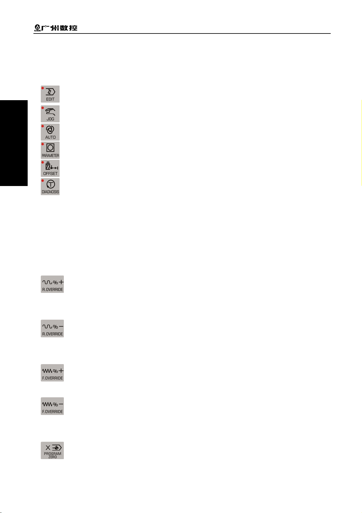
3.3.2 Operation Mode Select Key
The keys are identified by a sign and letters. The user can finish the corresponding function by
pressing an operation mode select key. The meaning of each key is as follows:
selects Edit operation mode
OPERATION
selects Manual operation mode
selects AUTO operation mode
selects Parameter operation mode
selects Tool Offset operation mode
selects Diagnosis operation mode
3.3.3 Function Key
The keys are indicated by a sign and letters. With a function key pressed, its function is enabled. The
meaning of each key is as follows:
Rapid override increase increases the rapid traverse override in MANUAL operation
mode, and increases the speed override of G00 command in AUTO operation mode.
Rapid override decrease decreases the rapid traverse override in MANUAL operation
mode, and decreases the speed override of G00 command in AUTO operation mode.
Feedrate override increase increases the feedrate override in MANUAL operation mode,
and increases the speed override of G01 command in AUTO operation mode.
Feedrate override decrease decreases the feedrate override in MANUL operation mode,
and decreases the speed override of G01 command in AUTO operation mode.
X axis reference point return is only valid in MANUAL/AUTO operation mode. (In this
manual, the program reference point is also called the program zero point)
8
Page 29
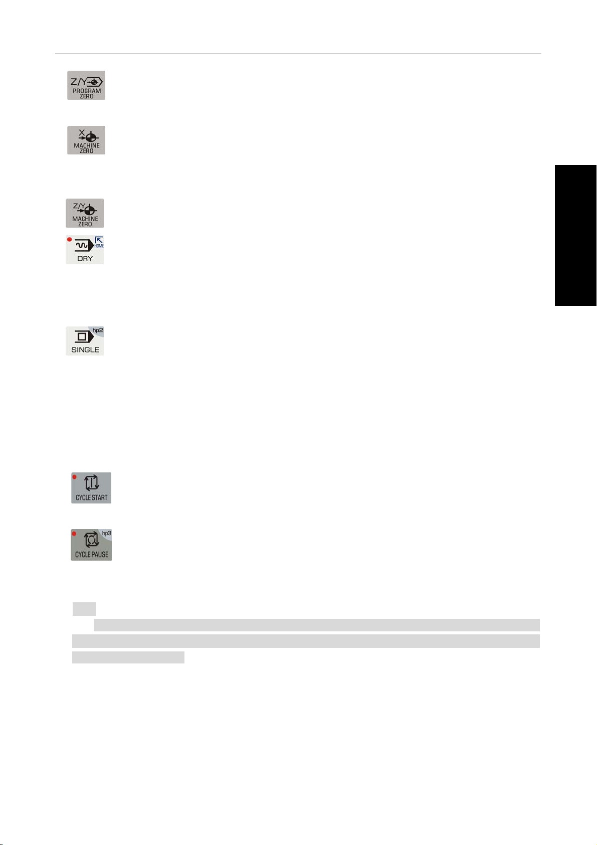
Chapter Three Operation Panel
Ⅰ
Z axis program reference point return is only valid in MANUAL/AUTO operation mode.
X axis machine reference point return only valid in MANUAL operation mode (In this
manual, the machine reference point is also called the machine zero point).
Z axis machine reference point return only valid in MANUL operation mode.
Dry run key When Dry Run is selected in AUTO operation mode to execute commands,
whether M, S, T commands are valid is determined by bit parameter P401_d7. After the Dry
Run state is exited, the coordinate of each axis of the system automatically resumes to the
one before Dry Run.
Single/Continuous key selects Single/Continuous mode in AUTO operation mode; in
other operations, it is for the hp function.
3.3.4 Cycle Start Key and Cycle Pause Key (Feed Hold key)
In AUTO operation mode, they are respectively used to start and suspend the program execution. The
meaning of each key is as follows:
OPERATION
Cycle Start key starts the program in AUTO operation mode, and then the program is
executed automatically; moves the coordinate axis in MANUAL operation mode.
Cycle Pause key (Feed Hold key) suspends the execution in MANUAL or AUTO
operation mode; in other operation modes, it means the hp function.
【Note】
There are two letters “hp” (help) on the upper right corners of some keys. In total, there
are 7 Help keys, which are hp0~hp6; in different operation modes, when the main key is
invalid, the hp is valid.
3.3.5 Manual Axis Control Key
In MANUAL operation mode, the meanings of manual axis control keys are as follows:
9
Page 30
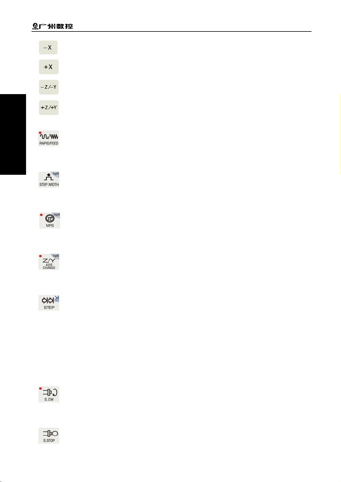
GSK928TD Turning CNC System User Manual
Ⅰ
In MANUAL operation mode, X axis is moved in negative direction.
In MANUAL operation mode, X axis is moved in positive direction.
In MANUAL operation mode, Z axis is moved in negative direction.
OPERATION
In MANUAL operation mode, Z axis is moved in positive direction.
RAPID/FEED key In MANUAL operation mode, it switches between rapid traverse rate and
feedrate.
In MANUAL operation mode, it is Single Step/MPG Step Width Selection; in other
operation modes, it is the hp function.
In MANUAL operation mode, it is MPG control selection and axis selection; in other
operation modes, it is the hp function.
In MANUAL operation mode, it is Z/Y axis selection, which is invalid for 928TD; in other
operation modes, it is the hp function.
Step/JOG key It selects Step/JOG operation in MANUAL operation mode.
3.3.6 Manual Auxiliary Function Key
The keys below are used for controlling and completing a variety of auxiliary functions of the machine
tool. The meaning of each key is as follows:
Spindle CW rotation The spindle rotates in CW direction (viewed from the tailstock to the
chuck)
Spindle stop The spindle stops rotating.
10
Page 31

Chapter Three Operation Panel
Ⅰ
Spindle CCW rotation The spindle rotates in CCW direction (viewed from the tailstock to
the chuck)
Coolant control switches between coolant ON/OFF.
Spindle gear shift selects the speed of each spindle gear for the machine tools equipped
Tool change key selects the next tool whose tool number is adjacent to the current one.
3.3.7 Edit Key
Key Designation Function
OPERATION
with multi-speed spindle motors and control circuits.
Press this key for confirmation after input.
ENTER key
INPUT key Input the desired contents
ALTER key
DELETE key
ESCAPE
key
HOME key
END key
In Edit operation, press it to switch between word
insertion/alternation;
In other operations, it has specific meanings.
In Edit operation mode, press it to delete words, blocks or a
whole program.
In other operations, it has specific meanings.
Press it to cancel the current input data, or exit the operation
state;
Press it to quit the current operation or setting.
In AUTO operation mode, it indicates “Dry Run”;
In EDIT operation mode, it moves the cursor to the beginning
of the current line.
In MANUAL operation, it indicates “STEP”;
In EDIT operation, it moves the cursor to the end of the current
line.
11
Page 32

GSK928TD Turning CNC System User Manual
Ⅰ
Key Designation Function
In AUTO operation mode, it means “Single/Continuous”
OPERATION
hp0
hp1
3.3.8 Reset Key
SINGLE
BLOCK key
Cursor move
keys
Page
change keys
program execution.
In EDIT operation mode, it means “Single/Continuous” analog
program execution.
In other operations, it means the hp function.
In Edit/Parameter/Tool Offset operation mode, they control the
movement of the cursor;
In other operation modes, they are hp functions or have other
specific meanings.
In Edit/Parameter/Tool Offset operation mode, they are used
to turn pages up and down.
In Manual/Auto operation, they have specific meanings.
Reset causes the system to enter RESET state.
12
Page 33

Chapter Four System Operation – Safety Protection
Ⅰ
CHAPTER FOUR SYSTEM OPERATION
This chapter describes in detail the operation and precautions of each functional module of the CNC
system. Before operating the machine, please thoroughly read this chapter.
4.1 System Power-on, Power-off, Initial State, Modal State, and Safety Protection
4.1.1 Power On
There is no power switch on the operation panel of this CNC system. The user may install a power
switch if necessary, so as to prevent the system from electric impact.
Before turning on the system, please confirm that:
1) The machine is in normal status;
2) The voltage of the power supply is in accordance with the requirements;
3) The connection is correct and firm.
OPERATION
The operation procedures for System Power On are as follows:
1) First turn on the power main switch;
Turn on the system power switch, then the system displays the initial screen as shown in fig. 4-1. In
this state, press any key other than
2) The following steps are completed in order after system power on.
key to enable the system to enter EDIT operation mode.
Fig. 4-1 System initial screen
z System control program loading
z System self-check and initialization
z System parameter loading and check
z I/O interface initialization
z User program loading and check
【Note】
1) Do not press any key on the operation panel during system power on. If the system enters
the key test interface, please press RESET key to exit.
13
Page 34

Ⅰ
OPERATION
GSK928TD Turning CNC System User Manual
4.1.2 Power Off
The operation procedures for system power off are as follows:
1) Press the system power switch to cut off the power.
2) Turn off the main power switch of the machine.
Before turning off the system, please confirm that:
1) The X and Z axes of the system are at the halted state;
2) The auxiliary functions (e.g. spindle, cooling) are OFF;
3) The power is cut off.
【Note】
1) In general, if it is the first time that the system is powered on, self-check and
initialization should be performed first.( This procedure is done by the machine tool
builder rather than by the user. Otherwise, the parameters set by the machine tool
builder may be lost. )
2) For the procedures of turning off the power of the machine, please see the user manual
provided by the machine tool builder.
4.1.3 Initial State and Modal State of System and Program
4.1.3.1 Initial State and Modal State of System
The initial state of the system is the specific state to which a function is automatically set upon
system power on; therein, none of the auxiliary functions has actual output.
The modal state of the system is the state that a function remains in after the system executes this
function.
Initial state and modal state of the system:
System state Initial state of the system Modal state
System machine coordinate system Remains in the state of last
Power-On.
System tool nose coordinate system Remains in the state of last
Power-On.
In Auto operation: 30mm/min
Cutting feedrate: F
Frequency-conversion spindle speed: S S200 Keeps until being changed
Spindle gear
Manual slow feed/rapid feed state Slow feed Keeps until being changed
Feedrate override Remains in the state of last
Rapid override Remains in the state of last
Spindle state M05 Spindle stop Keeps until being changed
Coolant state M06 coolant OFF Keeps until being changed
Chuck state M11 Chuck release Keeps until being changed
Lubricant state M33 Coolant OFF Keeps until being changed
T tool number state Remains in the state of last
Tailstock state M79 Tailstock run-out state Keeps until being changed
In Manual operation: Remains in
the state of last Power-On
Gear-shift spindle gear: S0
Frequency-conversion spindle
gear: M41
Power-On.
Power-On.
Power-On.
Keeps until being changed.
Keeps until being changed.
Keeps until being changed.
Keeps until being changed
Keeps until being changed.
Keeps until being changed
Keeps until being changed
14
Page 35

Chapter Four System Operation – Safety Protection
Ⅰ
4.1.3.2 Initial State and Modal State of Program
The initial state of the program is the state automatically set by the system by means of initialization
before a machining program is executed; i.e., the initial default state for the default programming word
and speed word when the system executes the first command of the machining program.
Program initial states of the system are as follows:
G function: G00, G97, G98;
Cutting speed: 30mm/min;
Auxiliary function: Current state
System coordinates: Current coordinates, which are the ones after the last automatic
program execution or after the last manual operation.
G function modal state means that once a word is set, it keeps unchanged until it is changed by
other G modal commands belonging to the same group. The meaning of the modal state: after a G
command is executed, it is unnecessary to input it again if it needs to be used in the following blocks.
The modal G commands are classified into the following three groups, and in each group, only one
command is in the modal state.
Group 1: G00, G01, G02, G03, G05 (Initial state: G00)
Group 2: G96, G97; (Initial state: G97)
Group 3: G98, G99; (Initial state: G98 F30)
The non-modal commands are only effective in the current block. They must be specified each time
they are used.
【Note】
In AUTO operation mode, when the system executes the first command, or executes the first
OPERATION
command after executing M20, or selects a block between the first lock and the last block as its first
command, it will automatically resumes to the program initial state.
4.1.4 Safety Protection
A series of safety protection is set for the CNC system, so as to protect the operator as well as the
machine tool. (Y axis function is invalid)
4.1.4.1 Hard Limit Protection
For the machine tools mounted with limit switches, the system can detect the switches. When the
slide carriage of the machine tool moves and presses down a limit switch, the system will stop feeding
without turning off the other auxiliary functions, and then the program execution is stopped, with the hard
limit alarm being displayed on the screen.
After the stroke limit alarm is issued, the user can select MANUAL operation mode and then press
the axis move key
displayed on the screen will disappear.
that moves the carriage in the reverse direction to exit the stroke limit, then the alarm
【Explanation】
15
Page 36

GSK928TD Turning CNC System User Manual
Ⅰ
1) The positive stroke limit detection of X, Y and Z axes shares the same pin +TL, and the negative
limit detection shares the same pin –TL; If a positive hard limit alarm occurs, all the axes cannot
be moved in positive direction other than in negative direction; and vice versa.
2) When the limit switch hits the limit stopper, the limit signal is generated; The length of the
effective part of the hardware stopper signal should be greater than 300 mm, to prevent the
signal effective area being exceeded.
OPERATION
3) If the “limit emergency stop” mode is set by bit parameter P402_d7=1, there may be a large
error between the coordinates displayed on the system and the actual ones after the limit
stopper is hit. In such a case, the machine coordinates must be readjusted.
【Related parameters】
Bit parameter: P402_d7, P404_d6, P404_d1.
Therein:
Bit parameter P402_d7 sets the modes of the hard limit alarm;
Bit parameter P404_d6 sets whether the hard limit alarm is detected;
Bit parameter P404_d1 sets the level of the hard limit alarm for each axis.
When bit parameter P404_d1=1, the alarm is set to high level. The positive limit switch +X, +Y or +Z
of each axis should be a normal closed contact, and connected to X/Z/Y positive limit input interface +LT
in series (an alarm occurs if open ); the negative limit switch -X, -Y, -Z of each axis should also be a
normal closed contact, and connected to X/Z/Y negative limit input interface -LT in series; it is
recommended that the user select a normal closed contact for the hard limit of each axis. The
connection is shown as the figure below:
When bit parameter P404_d1=0, the alarm is set to low level. The positive limit switch +X, +Y or +Z
of each axis should be a normal open contact, and connected to X/Z/Y positive limit input interface +LT in
parallel (an alarm occurs if closed ); the negative limit switch -X, -Y, -Z of each axis should also be a
normal open contact, and connected to X/Z/Y negative limit input interface -LT in parallel; The
connection is shown as the figure below:
4.1.4.2 Soft Limit Protection
1) Mechanical soft limit protection
16
Page 37

Chapter Four System Operation – Safety Protection
Ⅰ
Mechanical soft limit protection is used to limit the movement range of the machine coordinates, in
order to prevent the slide carriage from moving beyond the range. If the machine position (machine
coordinates) exceeds the range, the mechanical soft limit alarm is issued.
Method of releasing the overtravel alarm: In MANUAL operation mode, move the carriage in the
opposite direction (e.g. if the positive overtravel occurs, move the carriage in the negative direction; and
vice versa).
2) Tool nose soft limit protection
Tool nose software limit protection is used to limit the movement range of the tool nose coordinates,
to prevent the range from being exceeded by the tool nose. If the tool nose position (tool nose
coordinates) exceeds the range, the tool nose soft limit alarm is issued.
Method of releasing the overtravel alarm: In MANUAL operation mode, move the carriage in the
opposite direction (e.g. if the positive overtravel occurs, move the carriage in the negative direction; and
vice versa).
【Explanation】
During the movement, if the coordinates exceed the software limit range, the axes will decelerate to
stop.
【Relative parameters】
P009, P010: The max. stroke of tool nose software limit in the positive/negative direction of Z axis;
P011, P012: The max. stroke of tool nose software limit in the positive/negative direction of X axis;
P013, P014: The max. stroke of tool nose software limit in the positive/negative direction of Y axis;
P015, P016: The max. stroke of mechanical software limit in the positive/negative direction of Z axis;
P017, P018: The max. stroke of mechanical software limit in the positive/negative direction of X axis;
OPERATION
P019, P020: The max. stroke of mechanical software limit in the positive/negative direction of Y axis;
Bit parameter P404_d4 and P404_d3 respectively set whether the mechanical and tool nose software
limit alarms are valid.
4.1.4.3 Emergency Stop Alarm (Stopping System Emergently)
There is an external emergency stop input terminal ESP among the system interfaces. The user
should connect the normal closed contact of the red mushroom emergency button on the panel to the
terminal. In case of emergency, press the Emergency Stop button to cause the system to enter
emergency stop state, then the system will stop all the feed and turn off the spindle and cooling, issuing
the alarm “Emergency Stop” (If there are other popups displaying on the screen, the emergency stop
function is executed firstly, then the alarm “Emergency Stop” is displayed later).
After the cause of emergency stop is removed, press the Emergency Stop button in the direction of
arrow, then the button will lift automatically, cancelling the emergency stop signal.
When the system is in the emergency stop state, if the external emergency stop signal has been
cancelled, press RESET key to exit the state and return to the operation mode before emergency stop.
When the system is in the emergency stop state, if the external emergency stop signal is not
cancelled, it is forbidden to operate the system in Manual, Auto and Diagnosis operations; but the user
17
Page 38

GSK928TD Turning CNC System User Manual
Ⅰ
can press RESET key to remove the alarm window, and switch the control to Edit, Parameter or Tool
Offset operation mode; if the emergency signal is not cancelled in Edit, Parameter or Tool Offset
operation, press RESET key to remove the alarm window, then it is available to operate system.
If Emergency Stop occurs during movement, there may be a large error between the system
displayed coordinates and the actual ones. Thus the user must readjust the machine coordinates. When
the Emergency Stop button is pressed, the system will execute a series of emergency treatment, which
OPERATION
is shown as follows:
1) During emergency stop, the system stops all the feed; program execution stops; the spindle
stops and the cooling and lubricating are turned off.
2) During emergency stop, the system automatically sets the states of chuck and tailstock saved in
the memory to M11 and M79 respectively. After the emergency stop is released, the states of
the system chuck and tailstock are M10 and M78 respectively when their foot switches are
pedaled for the first time.
3) During emergency stop, if the system is executing commands such as tool change, chuck,
tailstock or gear shift, the execution will be stopped immediately (tool post positive/negative
rotation signal is cancelled, and whether chuck and tailstock are cancelled depends on the
parameter setting); here, the system assumes that the tool post, chuck, tailstock and gear are in
uncertain positions, and issues red flashing. Only after the emergency stop alarm is released,
can the system recover to the normal state by re-performing the operation successfully, or by
turning off the system and then on.
4) During emergency stop, the interface output signal of MDLY keeps unchanged. How to process
the interface control signals other than those of MDLY, spindle, coolant and lubricant is
determined by parameters. If P403_d3 is set to 0, only the output signals of the spindle, coolant
and lubricant are turned off; if P403_d3 is set to 1, all the interface control signals including the
chuck and tailstock are turned off.
5) After the emergency stop alarm is released, if the system is in the Dry Run state in Auto
operation mode, it will exit the Dry Run state; if the system is in Rapid Traverse state in
MANUAL operation mode, it will automatically enter Feed state; the set F value keeps
unchanged; and the spindle analog voltage keeps unchanged; the states of other functions
except the above are in program initial states.
6) After the emergency stop alarm is released, the time counting of low-pressure detection function
and automatic lubricating control function will be restarted.
【Special attentions】
1) The standard Emergency Stop function executed by the system is the function of turning on or
turning off the system output signals uniformly. The user can set it as follows: In Manual/Auto
operation mode, after Emergency Stop button is pressed, and the system executes the standard
Emergency Stop function, the system executes an additional M74 custom command once (only
when in MANUAL/AUTO operation mode and when there is a solidified M74 command in
the system, the execution is available). This function is applicable to some special machine
18
components and is used only when some of the output signals are required to turn off and some
Page 39

Chapter Four System Operation – Safety Protection
Ⅰ
maintained. If there is an alarm occurs during the execution of the M74 custom command, the
execution is stopped. After the emergency stop button is pressed, if the solidified M74 custom
command is being executed, the system will automatically terminate the command when it
proceeds to an axis move command or tool change command,
2) In Manual/Auto operation mode, when the M74 custom command can be executed in Emergency
Stop state by setting a parameter (P412_d1=1), there is a prompt “+M74” ( indicating the M74 is
being executed) added on the emergency stop window (if there is a solidified M74 custom
command in the system).
3) For the programming, debugging and solidification of M74 custom command, please see Chapter
Eight “Custom Command Programming” in this manual.
4) Be careful to use M74 function during Emergency Stop. The function is only applicable to some
special machine tools.
【Relative parameters】
When bit parameter P404_d7 is set to 0, the external emergency stop signal is valid; when it is set
to 1, the signal is invalid.
When bit parameter P403_d3=0: If the emergency stop alarm is valid, the system only turns off the
output signals of the spindle, cooling and lubricating.
When bit parameter P403_d3=1: If the emergency stop alarm is valid, the system turns off the
output signals of all auxiliary functions.
Parameter P404_d7 is set for the convenience of system debugging. In the on-line state, it must be
set to the valid state. Otherwise, it cannot provide protection.
Parameter P412_d1 sets whether M74 custom command is executed in the emergency stop state.
4.1.4.4 Drive Unit Alarm
OPERATION
When the CNC system is connected to the alarm output signal of a drive unit, and the drive unit
alarm is issued, the system will automatically stop all the feed, and prompt Z/X axis drive unit alarm on
the screen. All the axes, as well as the program execution, are stopped immediately. Here, check the
drive unit and relative components to remove the fault and then power on the system after power-off.
If the alarm occurs during movement, there may be a large error between the system displayed
coordinates and the actual ones. Therefore, the user must readjust the machine coordinates.
In MANUL operation mode, if the alarm occurs, all the axes movement is stopped.
In AUTO operation mode, if the alarm occurs, it is forbidden to execute the program.
【Relative parameters】
When bit parameter P404_d5 is set to 0, the drive unit alarm is detected.
Bit parameter P405_d4, P405_d3 and P405_d2 set the alarm level of the drive unit respectively for
Z, X and Y axes.
4.1.4.5 Other Alarms
When other alarms are issued in the system, they are displayed on the screen. Here, the user can
handle them according to prompts and the countermeasures described in Chapter Six Alarm Message.
19
Page 40

GSK928TD Turning CNC System User Manual
Ⅰ
4.1.4.6 Power Off
In case of emergency during machine running, the user can turn off the machine power immediately,
so as to prevent accidents.
However, if the power is turned off during coordinate axes movement, please note that there may be
a large error between the system-displayed coordinates and the actual ones after power-on. The user
OPERATION
must readjust the coordinate coordinates by performing machine zero point return or other means, in
order to make the system displayed coordinates coincide with the actual ones.
4.1.4.7 Reset Operation
When abnormal system output or coordinate axis move occurs, press RESET key to cause the
system to enter Reset state as follows:
1) All axes decelerate to stop.
2) Bit parameter P403_d2 sets whether M function (spindle, coolant) output is valid.
3) Automatic operation ends, and modal functions and states are kept.
4) The system is in G00, G97, G98 state; F value, as well as the spindle analog voltage output,
keeps unchanged.
5) The system terminates the operation in progress, and returns to the initial interface of the current
operation mode.
【Special attentions】
1) The standard Reset function executed by the system is the function of turning on or turning off the
system output signals uniformly. The following function can be set: In Manual/Auto operation,
after Reset button is pressed, and the system executes the standard Reset function, the system
executes an additional M73 custom command (only when in Manual/Auto operation mode and
when there is a solidified M73 command in the system, the execution is available). This
function is applicable to some special machine components and is used when only some of the
output signals are required to turn off and some maintained. If there is an alarm occurs during the
execution of the M73 custom command, the execution is stopped.
2) In Manual/Auto operation mode, when the M73 custom command can be executed in Emergency
Stop state by setting a parameter (P412_d2=1), there is a prompt “+M73” ( indicating the M73 is
being executed) added on the reset window (if there is a solidified M73 custom command in the
system).
3) For the programming, debugging and fixing of M73 custom command, please see Chapter Eight
“Custom Command Programming” in this manual.
4) Be careful to use M73 custom function during Reset. The function is only applicable to some
special machine tools.
【Relative parameters】
20
Page 41

Chapter Four System Operation – Edit
Ⅰ
When bit parameter P403_d2=0: After pressing Reset key, the system will turn off the output
signals of the spindle and cooling.
When bit parameter P403_d2=1: After pressing Reset key, the system will keep the output states
of the spindle and cooling before Reset.
Parameter P412_d2 sets whether M73 custom command is executed during Reset.
4.2 Operation Mode Selection for CNC System
The operation modes are directly selected by the operation mode keys in this system. It is available
to switch different modes directly, thus realizing simple, convenient and visible operation.
The screen shown in Fig. 4-1 is displayed after system power-on. If no key is pressed, the screen
keeps unchanged. When a key on the panel is pressed, the system enters Edit operation mode.
4.3 Edit Operation Mode
Edit operation mode is to operate the workpiece programs by using the system operation
panel. For each step, the system provides corresponding intelligent prompt messages. Also, the user
can press the hp2 key on the upper right corner of the system to view the list of the system operation
keys in Edit operation mode.
The explanations for the input format and examples about related setting and operation in the
manual are as follows: The meanings and use of the function keys to be pressed are described at the
beginning of the manual; the letter keys, numeric keys to be input are indicated by an underline; the
OPERATION
prompt messages of the system are indicated by a rectangle.
When setting or inputting an item, or during the man-machine dialogue, if ESC key is pressed
before confirmation, the current operation is quit.
◆ The major functions of the Edit operation mode are:
☆ To select, add, rename, copy and delete the workpiece programs;
☆ To input, insert, modify and delete the contents of the workpiece programs selected;
☆ To transfer workpiece programs between U disk and system through the USB interface.
☆ To transfer workpiece programs between external computer and system through the RS232
communication interface;
☆ To transfer workpiece programs between two CNC systems through the RS232 communication
interface;
☆ To compile and save programs
☆ To input variables and macro character strings
Press the operation mode select key
mode consists of two main pages, which are the program directory search page and program editing
to enter EDIT operation mode. The EDIT operation
page. The program directory search page is shown as Fig. 4-2.
21
Page 42

GSK928TD Turning CNC System User Manual
Ⅰ
OPERATION
Middle
Lower
middle
[EDIT] DDIRECTORY
Name Size Remark Latest
%
000 1KB
%
001 1KB
%
002
%
020 1KB
%
032
EDIT
1KB
1KB
Program count 5 Free memory 394KB
Curre Prog No.020
G00 X0 Z0
G0 X115 Z155
[Key prompt]
G50 X150 Z25
[U] Enter USB communication
G00 X300 Z10
[R] Enter RS232 communication
G50 X250 Z35
JOG
AUTO
Pro.Size 1KB
Name Size Remark Latest
PARA
OFFT
DIAG
Top
Upper middle
Popup window
Bottom
Fig. 4-2 Program directory search
◆ Explanations for the contents displaying on each area of the page
Top: Current program number and occupied storage capacity (program size), prompt key hp2 for
system function operation method;
Upper middle:
Middle
: Displaying the program names, sizes and remarks saved in the system
The system arranges the programs in terms of the name, size, remark or latest.
Lower middle
Bottom
: Displaying the number of programs stored in the system (up to 255) and the remaining
: Operation prompt messages
storage capacity for programs.
Popup window
: Displaying the operation prompt messages.
【Note】
When pressing hp2 key, the system prompts “Program directory interface message prompt”, which
introduces the functions of the keys to be used.
4.3.1 Part Program Directory Search
The part program directory search page displays the number of programs stored in the system. All
the programs can be arranged in the following four orders:
1) Sort by name: Sorting by the program numbers from the top to bottom, and from the left to right;
2) Sort by size: Sorting by the size of the programs, from top to bottom, and from left to right;
3) Sort by remarks: Sorting by the size of the first 12 strings in the first line of the programs, from
top to bottom, and from left to right;
4) Sort by latest: Sorting by the time that the programs are input, from top to bottom, and from left to
right.
The user can retrieve all the programs by pressing
and cursor keys and
and page keys. 12 programs can be displayed on one screen; pressing key turns the
22
Page 43

Chapter Four System Operation – Edit
Ⅰ
screen to the previous page, and pressing turns the screen to the next page; Pressing
or key sorts the programs by name, size, remark or latest.
4.3.2 Selecting, Creating, Deleting, Renaming and Copying a Part Program
It means the operation of selecting, creating, deleting, renaming or copying a part program.
【Note】
1. Up to 255 programs can be operated, from number %000~%254. When operating a program
number bigger than 254, the system prompts “E160 Input program number error”.
2. If there are no part programs in the system, or it is the first time that the system is used, the
system automatically creates and selects No. %000 program as the current program. If there are
part programs in the system, the system arranges the programs which existed before last
power-off according to their numbers.
3. The system supports multiple inputs, with the leading zero omissible. E.g. inputs the program
with name %003. Press INPUT key, and then input 0 0 3; or 0 3; or 3 .
4.3.2.1 Selecting and Creating a Part Program
The steps of selecting a part program or creating a new part program are as follows:
① Press INPUT key in EDIT operation mode;
② Input the program number to be selected using the keyboard, or input a program number not
OPERATION
included in the program directory as a new program number;
③ Press ENTER key;
④ Then the part program selection or creation is completed. The screen displays the contents of
the program, and the system enters the program edit page.
【Note】
1) After selecting a program, the user can change the desired program only through the above
steps; once a program is selected, it keeps unchanged even if the power is turned off.
2) If the input part program does not exist in the program directory, a new program with the input
program number is created and taken as the current program.
【Example】
Example 1: The procedures of creating a part program with number %20 when it is not included in
the program directory:
Press keys: INPUT 2 0 ENTER. The new program with name %020 is created,
and the system enters program edit page.
Example 2: Procedures of selecting the part program with number %001 when it is included in the
program directory:
Press keys: INPUT 1 ENTER. The program with number %001 is selected, and the
system enters program edit page.
23
Page 44

Ⅰ
OPERATION
GSK928TD Turning CNC System User Manual
4.3.2.2 Deleting a Part Program
The procedures of deleting a part program are as follows:
① Press INPUT key in Edit operation mode;
② Input the program name to be deleted using the keyboard;
③ Press DELETE key, then the system prompts: ENTER-Confirm Deletion ESC-Exit Deletion;
④ Press ENTER key to delete the part program whose number is input; or press ESC key to cancel
the deletion, and returns the control to the Edit operation mode.
【Note】
1) If the program to be deleted does not exist, the system prompts “E100 The program to be
deleted does not exist;
2) If the program to be deleted already exists: when it is not the current program, it is deleted from
the program list; when it is the current program, it is deleted from the program list, and the
system takes the program with the smallest number on the list as the current program; when
there are no programs existing after deletion, the system automatically creates an empty
program with name 000 as the current program.
【Example】
Example: The procedures of deleting the program with number %003 are as follows:
Press keys: ENTER 3 DELETE ENTER. The program with number %003 is deleted
from the part program storage area.
4.3.2.3 Deleting All Part Programs
It is the operation of deleting the program area in the program directory search page, i.e. deleting all
the programs once; the procedures are as follows:
Press ① INPUT key in the state of part program directory search;
Input ② , from the keyboard;
③ Press DELETE key, then the system prompts: ENTER-Confirm to delete all programs
ESC-Escape deletion;
④ Press ENTER key to delete all the programs; press ESC key to cancel the deletion, and return
the control to the Edit operation mode.
【Note】
After all the programs are deleted, the system will create an empty program with a name 0000 as
the current program.
4.3.2.4 Renaming a Part Program
The part program renaming is to replace the name of the current program by a new one. The new
program is taken as the current program. The procedures are as follows:
① Press INPUT key;
24
Page 45

Chapter Four System Operation – Edit
Ⅰ
② Input a program number which does not exist in the program directory, and press ALTER key to
change the current program name to the one input.
【Note】
If the input program number already exists, the system prompts “E166 The program to be
renamed already exists”. Input another name after the prompt disappears.
【Example】
Example: The procedures of renaming the current program %000 as %005 are as follows:
Press keys: INPUT 5 ALTER. Then the renaming is completed.
4.3.2.5 Copying a Part Program
It is to copy the contents of the current program to a new program. The newly created program is
taken as the current program. The procedures are as follows:
① Press Input key;
OPERATION
② Input a nonexistent program name as a new program, then press INPUT key to copy the
contents of the current program to the new program. The new program is taken as the current
program.
【Note】
If the input program name already exists, the system prompts “E161 The program to be copied
already exists”. It is available to input another program name again after the prompt disappears.
【Example】
Example: Procedures of copying the current program %000 to program %005 are as follows:
Press keys: INPUT 5 INPUT. Then the copy is completed.
4.3.3 Part Program Communication
The communication of part programs consists of part program sending and part program
receiving. The part programs can be sent from system to computer (CNC→PC), from system to U disc
(CNC→USB), or between two CNC systems (CNC→CNC); in addition, the system can receive the part
programs from a computer (PC→CNC), from another system(CNC→CNC), or from a U disc
(USB→CNC).
When pressing hp6 key on the program directory search page, the system prompts the part
program communication interface.
4.3.3.1 Sending Part Program (CNC→PC, CNC→USB, CNC→CNC)
Mode 1: RS232 serial communication
1) Before transferring the files, set the communication baudrates of parameter P414_d7 and
P414_d6. The communication baudrate is decided by the setting of the sender. Setting range:
25
Page 46

Ⅰ
OPERATION
GSK928TD Turning CNC System User Manual
9600, 19200, 38400(unit:bps). Factory standard setting: 9600 bps. For how to set the baudrate,
see Section 4.6 “Parameter Operation Mode” in PartⅠ Programming.
2) Output the part programs stored in the system to an external computer or CNC system:
① Connect the communication cable with the system power OFF, then turn on the system.
② On program directory search page, press keys: hp6 → R → hp2 in order;
③ Select the programs to be sent according to the help information of hp2.
④ Press ENTER key to send the programs;
⑤ Enable the external computer or CNC system to remain in receiving state; (For details, see
Chapter Five “RS232 and USB System Communication”)
⑥ The system sends the selected programs, and displays the progress bar at the same time till
the sending is completed; if multiple programs are selected, the system sends the programs
one by one in the ascending order according to their program numbers.
⑦ It is possible to interrupt the sending by pressing ESC key.
Mode 2: USB communication;
1) After entering USB communication mode, the system first checks whether a U disc has been
inserted. If no U disc is inserted, the system displays a prompt message box, prompting No USB
device inserted . If a USB disc containing a folder named “C001PRO” has been inserted, and
there are CNCxxx.TXT files in the folder, the files will be listed on the USB file directory box. If
there are no CNCxxx.TXT files in the C001PRO folder, the system prompts: USB device
specified directory: C001 PRO has no programs. If the folder named“C001PRO”does not exist in
the U disc, the system prompts: No specified directory in USB device: C001 PRO.
2) Output the part programs stored in the system to the U disc:
① Insert an UBS disc into the USB interface of the system;
② The system automatically opens the file directory of the U disc (when the U disc contains a
folder “C001PRO”, and the folder contains files “CNCxxx.TXT”). If the folder named
“C001PRO” does not exist in the USB root directory, the system will create one.
③ On program directory search page, press keys: hp6 → U → EDIT in order;
④ Select the programs to be sent according to the help information of hp2;
⑤ Press ENTER key to send the programs, and select the send mode according to the system
prompts.
⑥ The system sends the programs according to the selected mode, and displays the progress
bar till the sending is completed;
⑦ Press ESC key to exit the U disc.
4.3.3.2 Receiving Part Programs (PC→CNC, USB→CNC, CNC→CNC)
Mode 1: RS232 serial communication;
1) Set the baudrate and communication port of the communication software; (for details, see
Chapter Five “RS232 and USB System Communication” in Part Programming)Ⅰ
26
Page 47

Chapter Four System Operation – Edit
Ⅰ
2) Input the part programs stored in the external computer to the system; or transfer programs
between CNC systems; the procedures are as follows:
Connec① t the communication cable with the system power OFF, then turn on the system;
On the program directory ② search page, press keys: hp6 → R → EDIT in order;
Select the receive mode according to the system prompts;③
④ After confirming the system is in receive state, input the programs stored in the external
computer or CNC system to the CNC system.
The system inputs the programs according to the selected receive mode, and displays the ⑤
progress bar until the receiving is completed;
⑥ It is possible to stop receiving programs pressing ESC key in the progress of receiving.
Mode 2: USB communication;
1) After entering USB communication mode, the system first checks the U disc, and then opens the
folder “C001PRO” to list the “CNCxxx.TXT” files in the folder.
2) Output the part programs stored in the U disc to the CNC system:
Insert the U disc into the USB interface of the system;①
On the program directory ② search page, press keys: hp6 → U in order;
The system automatically opens the file directory of the U disc;③
Select the programs to be received according the help i④ nformation of hp2;
Press ⑤ ENTER key to receive programs, and select the send mode according to the system
prompts;
The system receive⑥ s part programs according to the selected receive mode, and displays the
progress bar until the receiving is completed;
OPERATION
Press ⑦ ESC key to exit the U disc.
【Note】
If the name of a program to be sent to the system already exists in the system, the system prompts
whether to replace the original one. Once replaced, the original program will be replaced by the
sent program.
4.3.3.3 Standard Format of TXT Part Program on PC
On a personal computer, the part program can be edited using TXT or LST text. However, the file
name and its contents must be edited in the standard format required in the system, so that the program
can be correctly sent to the system. The specifications are as follows:
1) On a personal computer, the user should name the part program file with suffix TXT or LST, e.g.
“CNC008.TXT”; It is recommended that the user use suffix TXT for the convenience of the part
program operation on the PC.
2) The first line of the TXT file must indicate the program number, in the format of “ % XXX ”, i.e. an
one-digit, two-digit or three digit number behind the percent, within a range of 0~254. No other
contents can be contained in the first line. The range of the program number must be within
0~254. Otherwise, the system fails to receive the programs and prompts corresponding error
27
Page 48

GSK928TD Turning CNC System User Manual
Ⅰ
messages. The program numbers are determined by the following two modes (USB and RS232)
after the CNC receives the programs:
◆ In system RS232 communication, the program name to be stored is subject to the
program number of the first line; i.e. the Arabic numerals XXX of the string “%XXX” in
the first line of the program sent by the PC.
The number of the program transferred by the USB is the Arabic numerals xxx of ◆
OPERATION
CNCxxx.TXT in the folder “C001PRO” in the U disc root directory.
Note: In system USB communication, The Arabic numerals XXX in string “%XXX” of the first line in
the program should be the same as the Arabic numerals XXX in CNCxxx.TXT in the folder
“C001PRO” of the U disc root directory.
3) The second line and the following are blocks. The format of a block must accord with the
requirement, and each block, ended with ENTER key, cannot contain more than 250 characters.
Otherwise, the system reports an error message “Block overlong in received program”
4) The comment area of the block can contain comments in Chinese.
5) The size of the TXT file cannot exceed the limit of the program storage capacity of the system.
Standard format of part program communication on PC:
TXT file format Explanation
%099
N0000 G50 X100 Z100 ; Setting coordinate
system
N0010 G00 X20 Z90 ;
G01 X10 Z80 ; Linear cutting
……
/N0250 G02 X30 Z20 R5 ; Circular cutting
N0260 ;T22 ; Tool change
N0262 M05
N0270 G04 D8
……
M20
Rapid positioning
1. When the system is receiving a program,
the program name %099 cannot be
omitted; the first line must be a
three-digit number between 0~254.
2. N**** is the line number of a block.
Blocks without N**** have no line
numbers.
3. The beginning of each line is a space.
4. For the block with a line number, there
is a space between the line number and
the command.
5. / indicates the block is skipped;
6. ; The contents behind it are comments.
4.3.4 Inputting and Editing the Contents of Part Program
The input part program consists of a number of blocks, and each block includes a block number,
commands, data, etc. The format of the program should be consistent with the general programming
rules described in Part Programming, and no alarm should occur during program compiling. For the Ⅱ
alarm prompts, see Chapter Six Alarm Message in Part Programming.Ⅱ Only after the correct program
contents are input according to order of the technological requirements, can the machine tool produce
qualified parts.
The system employs the full-screen edit mode, and the program edit page is shown in Fig. 4-3:
28
Page 49

Chapter Four System Operation – Edit
Ⅰ
【EDIT】 %001 Column 8 Line 3 Lines 11 Size 1KB hp2
N0000 G0 X100
N0010 X0
N0020 X100
N0030 X0
N0040 G1 X100 F80
Middle
N0050 X0
N0060 X100
N0070 X0
N0080 X100
N0090 X0
N0100 G1 Z100
N0120 M20
Fig. 4-3 Program editing
Explanations for each area of the interface◆
Top
: Program number and program size of the current program, number of lines, line and column at
which the edit cursor (prompt symbol of editable character on current position ) is located,
prompt key hp2 for system function operation;
Middle
: Program edit window;
Currrent editting program
compiling succeeds
To p
Popup
window
OPERATION
Popup window
: Displaying prompt information for operation.
【Note】
1. After pressing hp2 key, the system prompts “Program editing Help message prompts”,
introducing the functions of the help keys to be used.
2. When bit parameter P416_d0 is set to 1, it is forbidden to edit or alter a program, and the
system displays alarm message E174 Part programs are locked, and forbidden to
modify; when it is required to edit and alter a program, set the bit parameter P416_d0 to
0.
Meanings and use of edit keys on program edit page
1)
, cursor up and down keys
By pressing a cursor key once, the cursor moves up (or down) vertically till it reaches the
uppermost (or lowest) line, taking the current cursor column value as the reference movement
value. By holding the cursor key, the cursor moves up (or down) continuously till the first (or last)
block is reached, or till the key is released. When using the string search function (hp5), the two
keys are used for retrieving the desired string up and down.
2)
, Cursor left and right move keys
By pressing a cursor key once, the cursor moves one character towards left (or right). By
holding the cursor key, the cursor continuously moves to the left (or right) till the first (or last)
character of the block is reached, or till the key is released.
29
Page 50

GSK928TD Turning CNC System User Manual
Ⅰ
3) Line Home key: The cursor rapidly moves to the beginning of a line or the beginning of
the first word of the line. When repeating pressing the Line Home key, the cursor
location is switched between the beginning of a line and the first word of the line. By
pressing the Line Home key and Delete key together, the current line is deleted.
OPERATION
Line End key: The cursor rapidly moves to the end of a line.
4) Insert/Alter key:
Changing the edit input mode: By pressing the ALTER key once, the input mode
toggles between Insert and Alter, with the cursor displaying in different shapes. In
Insert mode, the cursor is a flicking underscore, while in Alter mode, the cursor
becomes a flicking and highlighted block cursor.
5)
6)
Input key: It switches the program edit state to the program directory search state,
displaying Please input program number;.
Page up and Page down keys
They are used for turning pages to display programs. When used in the function of
hp5 key, they move the cursor to Home/End page; when used in the function of hp3
key, they are used for other purposes.
7)
8)
9) hp2
hp3 key: Current program compiling.
Enter key:
It inserts a new line when the cursor is located at the beginning or the end of a line,
with the cursor moving to the new line; when the cursor is located in other position, it
moves to the beginning of the next block by pressing Enter
Delete key: It is for deleting a whole program or the characters in a block.
key: Help information for program editing.
key.
30
Page 51

Ⅰ
Chapter Four System Operation – Edit
10 ) hp4
key: On program edit page, the user can control the movement of the cursor using
a MPG, browsing the programs rapidly.
hp5
key: Help for system commands, part program string search, etc. If the program
number of the current program is 253 or 254, the operation of the program with
number 253 or 254 is added.
hp6
key: It prompts to display macro string list.
Rules for multi-function definition key
1) If the first letter in a line is a capital, the first key has the priority; if the first letter is lowercase
letter, the third or second key has the priority.
2) If a letter or string is input behind a number (0~9), a space between them will be created
automatically.
OPERATION
3) After a string is input, the cursor stays in the position that is the most convenient for inputting.
Table of values for multi-function definition keys
Panel display
>
<
thenthen
elseels e
;;;;;;;;;;;;;;;;;;;;;;;;;;;;
///////////////////////
First key
value
G r
M H =
X J >
Z Q <
S if
T L then
U E else
W / ;
Second
key value
Third key
value
Panel display
( )( )( )( )( )( )( )( )( )( )( )( )( )( )( )( )( )( )( )( )( )( )
and
or
*
First key
value
F N ( )
I P
K Space
D V and
R Y or
. *
- +
Second
key value
4.3.4.1 Inputting Program Contents
Third key
value
Note: Set the value of parameter P333 to 10 (program number automatic creation, similarly
hereinafter)
31
Page 52

GSK928TD Turning CNC System User Manual
Ⅰ
On program edit page, input the contents of a part program by the following steps:
① Create a new program by means of creating a new part program;
② After the block number N0000 is displayed, input a line of program contents from the keyboard;
③ After the input, press ENTER key to end the input of this line;
④ The system automatically creates the number of the next block for user to continue inputting;
⑤ After the last line of the program is input, press ESC key to end the input of the program.
OPERATION
【Note】
1) The first column of each line must be the space;
2) Up to 60 characters can be displayed for one block. If there are more than 60 characters, the
remaining ones are not displayable. If the cursor is at the end of a line, the cursor moves a
character towards left by pressing
3) The first column of each line is a space, which is created automatically by the system; the
number of the first column is 1, and that of the last column is 252; Only the cursor rather than the
character can be displayed at the first and last column; up to 250 characters can be edited in one
block.
key.
4.3.4.2 Inserting a Block
Insert a block or multiple blocks between two blocks; or insert a block or multiple blocks before the
current block. The procedures are as follows:
① For two adjacent blocks, move the cursor to the end of the first block or to the beginning of the
second block;
② By pressing Enter key, the system automatically creates a new block number between the
current block and the next block (the increment of the sequence number is the integer which is
1/4 of the value set in parameter P333. If the numbers are not enough, modify the number of the
next block.) and leaves one blank line.
③ Input the desired contents to the block;
④ After the input, if it is necessary to insert multiple blocks, press ENTER key; if only one block is
required to insert, this operation is unnecessary.
【Example】
Example: The operation procedures of inserting a new block M3 between block N0020 and block
N0030 are as follows:
Move the cursor to the end of block N0020 or to the beginning of block N0030; Press Enter
key, then input M3 for the new block.
4.3.4.3 Deleting a Block
The procedures of deleting all contents (including the block name) in one line are as follows:
① Move the cursor to the beginning of the block to be deleted;
② Press DELETE key;
③ Delete all the contents of the selected block.
32
Page 53

Chapter Four System Operation – Edit
Ⅰ
4.3.4.4 Inserting a Character in a Block
The procedures of inserting a character in a block are as follows:
① Pressing ALTER key to switch the input mode to Insert mode, i.e. the cursor is displayed as an
underscore;
② Move the cursor to the character behind the position where the contents are to be inserted;
③ Input the desired contents
④ Insert the desired contents before the character where the cursor is located.
【Note】
According to the requirement of the system, a space must be left between two words (a word means
a letter followed by digits) to separate them. The space can be created automatically during program
editing. However, it may not be created during insertion operation. In this case, the operator is required
to input the space, in order to keep the program complete.
【Example】
Example: The procedures of inserting 1 between X and 0 in the block N0020 G0
X0.0 Z0.0 are as follows:
Move the cursor to the bottom of 0 behind X , then input 1 . Then the screen
displays N0020 G0 X10.0 Z0.0
4.3.4.5 Deleting a Character in a Block
OPERATION
The procedures of deleting characters in a block are as follows:
① Move the cursor to the character to be deleted;
② Press DELETE key to delete the character where the cursor is located.
4.3.4.6 Altering Contents of a Block
Change the contents of a block. There are two methods depending on the input mode (Insert/Alter)
In Insert mode: Procedures of altering a block using the combination of insertion and deletion:
① Move the cursor to the character to be altered;
② Input the new contents;
③ Press DELETE key to delete the unnecessary contents;
In Alter mode: Procedures of directly altering the contents where the cursor is located:
① Press ALTER key to switch the cursor to Alter mode (the character where the cursor is located is
highlighted by a rectangle);
② Move the cursor to the character to be altered;
③ Input the new contents, then the cursor moves to the next character.
【Example】
33
Page 54

GSK928TD Turning CNC System User Manual
Ⅰ
Example: The procedures to alter X in block N0020 G0 X0.0 Z0.0 to U are as follows:
Switch the input mode to ALTER mode, move the cursor to the bottom of X , and then input U .
After alteration, the block becomes N0020 G0 U 0.0 Z0.0.
4.3.4.7 Inserting a Macro String
On program edit page, the procedures of inserting a macro string are as follows:
OPERATION
① Press hp6 key to display on the screen the macro string list;
② Select the contents to be input by pressing keys according to prompts.
【Example】
Example: Press hp6 key, then G key, and then input program contents: r = r * r / r. Here, the cursor
stays behind r.
【Note】
For details about the variables and statement programming, please see Chapter Seven Statement
Programming in Part Programming. Ⅱ
4.3.4.8 Storage Capacity for Programs
The system provides 400k storage capacity for storing programs from No.0~ No.252, and No.254.
Therefore, the size of a single program can reach 400K theoretically. For No.253, the system provides
another 4 M storage space.
【Explanation】
1) The screen displays the remaining program storage capacity, as well as the remaining storage
size of the system program area.
2) If the size of the program (No. 0~252, 254) being edited currently is greater than the max.
storage capacity (400k), the program cannot be saved. and the system prompts that the program
storage space is full: Edit area overflow. If the remaining storage space is insufficient, delete
some old programs.
3) The edit storage space for No. 253 program is 4 M, but the program cannot be saved.
4) If the size of a program is large, it takes longer time to save the program.
4.3.4.9 Operating No. 253 Program
As the size of No. 253 program can be up to 4M, the operation of this program is special. The
procedures are as follows:
1) The No. 253 program cannot be saved into the system. It is lost after power-off.
2) When No. 253 program is changed to other programs, the No. 253 program cannot be saved
neither, i.e. it will be lost;
3) The communication of No. 253 program is unavailable by using USB or RS232 mode.
【Note】
1) No.253 program cannot be saved.
34
Page 55

Chapter Four System Operation – Edit
Ⅰ
2) No.253 program cannot by copied or renamed.
4.3.4.10 Operating No. 254 Program
After selecting No. 254 program on program edit page, press hp5 key, then the help information
about how to edit, solidify and read No. 254 program appears. The operation procedures are as follows:
1) Key 5, for editing and solidifying No. 254 program:
When compiling No. 254 program, if the compiling fails, the system issues an alarm; if the
compiling succeeds, the program is saved to the solidification area (FLASH)
2) Key 4, for extracting No. 254 program:
It reads No. 254 program saved in the solidification area (FLASH) to the edit buffer area, to
update the program.
3) Key 6, for deleting the custom command of No. 254 program
If there is a custom command in the solidification area, the command will be displayed on the
screen. After the custom command in No. 254 program is deleted, there is no custom command
in the system solidification area; the help information dialog box for No. 254 program prompts
“No custom command in solidification area”
4) Press ESC key to exit the current state.
4.3.5 Function of hp5 Key
hp5 help key includes help for system commands, help for obtaining relative parameters of an arc,
rearrangement of line numbers, replacement of strings, cursor location, MPG cursor movement, etc.
OPERATION
If the program number of the current program is 253 or 254, hp5 help key adds the prompts for the
operation of No. 253 program or No. 254 program.
4.3.5.1 Help for Part Program Command
When hp5 1 are input on program edit page, the system prompts “Command help introduction”
interface; this function is capable of retrieving all the commands of the system, including G, M, S, T, F
commands. The operation procedures are as follows:
1) Press G, M, S, T, or F key to respectively view the corresponding explanation for the G, M, S, T or
F command.
2) Press INPUT key, then input the command number to be searched; the system displays the
meaning, function, format as well as explanation for the command number.
【Example】
Example: Searching the command help for G05
Press keys: hp5 1 INPUT G 05 ENTER, then the system prompts the meaning, function,
format and explanation for G05.
35
Page 56

Ⅰ
OPERATION
GSK928TD Turning CNC System User Manual
4.3.5.2 Help for Obtaining Relative Parameters of Arc
Input hp5 2 on program edit page, then the system prompts “Please input relative arc parameters”
interface; this function is for obtaining the parameters of an arc.
Input [start point coordinates] , [end point coordinates] , [circle radius ], then the system will
automatically calculate the relative parameters of the arc.
【Example】
As shown in the figure below: Coordinates of start point A (Z60,X10), coordinates of start pinot B
(Z40,X30).
[Please input relative arc parameters] (Explanation: X direction is the radial programming,
P413_d6=1 )
[Start point coordinates] Z: 60 X: 10
[End point coordinates] Z: 40 X: 30
[Circle radius] R: 20
After inputting the data above, the system will automatically calculate the following data:
CW circle center 1: Z: 40 X: 10 (The values of Z and X are:the coordinate values
of CW circle center 1.)
CCW circle center 2: Z: 60 X: 30 (The values of Z and X are:the coordinate values
of CW circle center 2.)
Start point -> Circle center 1: Z: -20 X: 0 (The values of Z and X are:the Z and X vectors
of start point A pointing to circle center 1.)
End point -> Circle center 1: Z: 0 X: -20 (The values of Z and X are:the Z and X vectors
of end point B pointing to circle center 1.)
Start point -> Circle center 2: Z: 0 X: 20 (The values of Z and X are:the Z and X vectors
of start point A pointing to circle center 2)
End point-> Circle center 2: Z: 20 X: 0 (The values of Z and X are:the Z and X vectors
of end point B pointing to circle center 2)
36
Page 57

Chapter Four System Operation – Edit
Ⅰ
4.3.5.3 Rearrangement of Program Line Numbers
Input hp5 3 on program edit page, then the system rearranges the programs, with the rearranged
program numbers increased based on the multiple of 10. (Parameter P333 is set to 10)
【Note】
1) After the block numbers are rearranged, if the skip command is used in programming, the
program skip error may occur.
2) When the value of parameter P333 is 0, the program number rearrangement function is invalid.
4.3.5.4 Replacement of Strings
Input hp5 R on program edit page, then the system prompts “String replacement” page; perform
the operation according to the system prompts. After the replacement of the string, all the characters to
be replaced are replaced from the current character where the cursor is located to the last character.
4.3.5.5 Cursor Position
OPERATION
The string search function provided by the system is used for locating the contents to be searched,
which is convenient for the user to search the desired contents. Press hp5 key on program edit page,
then the system prompts the functions of , , , and F key as follows:
1) Press
2) Press
3) After pressing F key, input the string to be searched in the current program, then press ENTER
key. After that, the cursor is located at the searched string, highlighted in red. In inputting the
string to be searched, the system automatically records the latest 10 times of string search. If
there is no record, nothing is displayed.
4) According to the system prompts, press
search the desired string in the current program. If the desired string does not exist in the current
program, the system prompts: Search completed, string not found
key to move the cursor to the first page of the current program.
key to move the cursor to the last page of the current program.
or to move the cursor up or down to
4.3.5.6 Cursor Movement by MPG
After the MPG is connected to the system, press MPG key on the program edit page. You can
quickly browse the programs by rotating the MPG to control the movement of the cursor when the MPG
LED indicator on the operation panel lights up. By pressing MPG key again, the LED indicator goes out.
In this case, it is unavailable to perform MPG operation. For the connection of MPG, see Part Ⅲ
Connection.
37
Page 58

GSK928TD Turning CNC System User Manual
Ⅰ
4.3.6 Compiling a Part Program
The compiling command key hp3 in the system is used for compiling a part program, and checking
the grammar error, logic error, and whether the coordinate data causes overtravel according to the
execution path of the part program, in a bid to reduce the alarm errors when the program is executed in
AUTO operation mode, and improve the safety of executing the part program.
OPERATION
By pressing the compiling command key, the system checks and compiles the part program from the
first block according to the execution path, and generates an object code which is convenient for
execution. If an error in the program is detected, the system stops the compiling, displaying the word
position and error number in the block where the source program error occurs, and prompting the user to
modify the error.
4.3.6.1 hp3 Compiling Command
On program edit page, press hp3 key, the system compiles the current program line by line. If an
error message is detected, a window『Program Alarm 』pops up. If no error exists in all commands, the
system displays: Current program compiling succeeded
The information of 『Program Alarm』consists of:
Error: indicates error codes (View Chapter Six Alarm Message in PART Programming Ⅱ
according to the codes);
Program: indicates contents in the error block;
Position: indicates error letter or word in the error block.
【Explanation】
1) Only those programs successfully compiled by hp3 can be executed in Auto operation mode.
2) The system automatically completes the compiling when the control is switched from edit
operation mode to other operation modes.
3) After『Program Alarm』appears during the compiling by hp3 key, the cursor automatically moves
to the error block by pressing any key.
4) During the execution of hp3 compiling command, the system starts execution from the first
block of the current program, assuming that the axes of the machine take the position of the
current workpiece coordinates as the start point. Therefore, for some special programs, the
stop position of each axis may affect the compiling; it is suggested that each axis stop in
advance at the machining start point.
4.3.6.2 Result Analysis of Program Compilation
On program edit page, there are two types of alarm due to program compiling error: [Program Alarm]
and [Program Compound Check Alarm]. Only when the above types of alarm are not issued, can the
compiling succeed.
Therein:
38
Page 59

Chapter Four System Operation – Edit
Ⅰ
Program alarm: means the alarms caused by the command error in the programming. The alarm
can be removed by inputting a correct command. It is not closely relative to the parameter setting.
Program compound check alarm: means the alarm which occurs during the program command
check (relevance check according to the setting of auxiliary parameters and interface parameters). It is
required to analyze the program in accordance with the setting of auxiliary parameters and interface
parameters, and then modify the program and parameter setting to remove the alarm.
【Example】
[Example for program alarm]:
When pressing hp3 key to compile a program, the alarm is displayed as follows:
[Program alarm]
Error E206:Missing message
Program:N0100 G92 Z300 P1
Position: P
[Example for program compound check alarm]
After the current program is compiled successfully by pressing hp3 key, and the control is switched
from the Edit operation mode to the other modes, the alarm is displayed as follows:
[Program comound check alarm]
Error E610: Illegal use of M78
This function is invalid.
4.3.6.3 Prompts of Program Compound Check
OPERATION
After the program is compiled, if no error is detected, in general, the program can be executed in
Auto operation mode. However, under the following conditions, the system displays the prompts of the
program compound check.
1) The range of tool nose soft limit or machine soft limit is exceeded.
During the execution of the program, if the range of tool nose soft limit or machine soft limit is
exceeded, the system displays the program compound check prompts when the control is switched from
EDIT operation mode to AUTO operation mode.
2)Inconsistent with the tool setting record
If tool setting inconsistence occurs during the execution of the program, the system displays the
program compound check prompts when the control is switched from the EDIT operation mode to the
AUTO operation mode.
【Example】
[Example for program compound check alarm]
E.g. When the tool is T0408 during tool setting, and there is T0308 in the program, it is inconsistent
with the tool setting record; When bit parameter P403_d4 is set to 1, an alarm message T0308
inconsistent with tool setting record T0408 pops up when the control is switched from the EDIT operation
mode to the AUTO operation mode.
39
Page 60

GSK928TD Turning CNC System User Manual
Ⅰ
4.4 JOG Operation Mode
In JOG (Manual) operation mode, the user can perform a certain operation pressing function keys
directly, or perform a certain setting or operation pressing letter keys. For each step, the system offers
corresponding intelligent prompt messages.
Descriptions for the relative setting or the input format and examples of relative operation are as
OPERATION
follows: The function keys required to press are indicated by a sign; the letter keys or numeric keys
are indicated by an underline; the prompt messages of the system are indicated by a rectangle.
If incorrect data is input during the input of letters or figures, press key to delete it , and then
input the correct data
When setting or inputting an item, or during the man-machine dialogue, if ESC key is pressed before
confirmation, it means the current operation is quit
In Manual operation mode, key is displayed on the upper right corner of the screen; After
pressing this key, a window pops up, displaying the directory of the operation keys in Manual mode;
by pressing this key again, the window is closed; by pressing other function keys directly, the window
is automatically closed.
Press operation mode select key
For the CNC machine tool, a large amount of work, such as the installation and debugging of a variety of
to enter Manual operation mode.
electrical components, debugging of motion performance, establishment of the coordinate system and
tool preparation, is completed in Manual operation mode.
After the Manual page is entered, the system performs necessary analysis and pre-check in accordance
with the user parameter list
result in serious accidents, the system locks the function of Manual operation, and pops up a window
displaying an alarm message; In this case, the user should modify relative parameters according to the
alarm message, and then perform Manual operation.
This system provides multiple modes for the execution of part programs. Before the execution, the user
can perform necessary setting in Manual operation mode, to ensure the safety during machining.
The main functions of Manu◆ al operation mode include:
The axes ☆ can be moved in JOG mode, STEP mode or MPG mode.
The axes ☆ can be moved by absolute
Establishment of machine coordinate system, establishment of workpiece coor☆ dinate system
Auxiliary function☆ s such as spindle, chuck, cooling, or tool post
☆ Tool setting
Real☆ -time display of the states of the machine tool, real-time alarm displayed in a popup window.
Note: 928TD system has no Y axis function.
and tool offset values. If the precheck finds that the Manual operation may
or incremental programming.
40
Page 61

Chapter Four System Operation - Jog
Ⅰ
w
p
m
The Manual page is displayed as fig. 4-4:
Popup
windo
Upper
left
Lower left
[JOG]
0289.850
X
0104.060
Z
EDIT
JOG
JOG
ESP Emergency
alar
sto
AUTO
PARA
T 01 00
100%
100%
S01 S0500
DIAG
r
G97 S0200
G98 F30
F 00100
OFFS
Fig. 4-4, Manual operation mode
Explanation for each area of the interface:◆
Top
: Displaying the manual feed operation mode, including JOG, STEP, X/Z MPG; prompt key
Top
OPERATION
Middle
right
for system function operation methods;
Upper left
Lower left
Middle right
: Displaying tool nose coordinates as well as machine coordinates;
: MDI input and alarm prompt area;
: Displaying the current states of the machine, including messages about the spindle,
cooling, lubricating, chuck, tailstock, rotating speed and cutting speed;
Popup window
: Displaying the system alarm messages.
Explanations for the display of auxiliary function states:◆
1) The states of auxiliary functions are indicated by an icon or corresponding instruction code sign;
2) A black sign indicates the current state; e.g. spindle, cooling, etc;
3) A red sign indicates the function is being executed;
4) A blinking red sign indicates that the function was unsuccessfully executed or interrupted (e.g.
reset, emergency stop) last time, and the system assumes that the corresponding function is in
an uncertain state. When the tool or chuck is in an uncertain state, it is unavailable to start the
machining program; Only by performing a successful operation or turning the power OFF then
back ON, can the system recover to the normal state.
5) When there is constant response detection for the chuck/tailstock, the green signal indicates a
normal state, while the yellow sign indicates an abnormal state;
6) The S behind the spindle gear indicates the spindle speed detected in real time;
7) Pressure detection icon : It is green when it is normal. It becomes h△ alf-empty yellow as soon
as the low pressure is detected; when the time that the low pressure lasts exceeds half of the
time set in P332, it turns to entirely-empty yellow;
8) G96/G97 and S indicate whether the mode is the constant surface speed cutting mode; S
indicates the set surface speed or rotating speed, unit: m/minor r/min;
9) G98/G99 indicates whether the mode is feed per rotation or feed per minute; F is the set cutting
speed;
10) F indicates the actual movement speed of the coordinate axis.
41
Page 62

Ⅰ
OPERATION
GSK928TD Turning CNC System User Manual
4.4.1 Coordinate Axis Movement
Before moving the coordinate axis, please determine the movement speed, movement
distance first. In case of emergency, press down the Emergency Stop button immediately.
4.4.1.1 JOG movement
By pressing key, the control can be switched from STEP or MPG mode to JOG mode.
【JOG movement】means holding a coordinate axis movement key to cause the machine slide
carriage to move continuously; When the key is released, the machine carriage decelerates to stop.
The meanings of axis movement keys are as follows:
X axis – direction movement key; X axis + direction movement key
Z axis/Y axis – direction movement key (That the indicator of key lights up is
for Y axis.)
Z axis/Y axis + direction movement key (That the indicator of key lights up is for
Y axis.)
Switching between Z and Y axes:◆
By pressing Z/Y axis switch key, the user can switch the operation between Z axis and Y axis; that
the Z/Y axis switch indicator lights up is for Y axis operation. (when bit parameter P405_d1=1, the
machine tool has Y axis, then the switch is valid). Note: 928TD system has no Y axis function.
When the machine tool is switched to Y axis operation, it is also the Y axis that is valid for operations
such as program reference point return and machine zero point return.
【Attention】
1) When the motor is running at a high speed, if the coordinate axis movement key
released, the machine carriage keeps moving instead of stopping immediately, because of the
automatic acceleration/deceleration of the system. The movement distance varies with the max.
motor speed, system acceleration/deceleration time and feedrate. The higher the speed is, and
the longer the acceleration/deceleration time is, the longer the distance the slide carriage moves;
has been
and vice versa.
4.4.1.2 Step Movement
By pressing key, the system can be switched from JOG mode or MPG mode to STEP
mode.
【STEP movement】indicates that the slide carriage moves a pre-set step width pressing a
coordinate axis movement key
42
once. The movement speed is executed at the selected rapid traverse
Page 63

Chapter Four System Operation - Jog
Ⅰ
rate or feedrate. However, the max. movement speed of Z, X, Y axis is respectively limited by parameter
P100, P101, P102.
By holding the key, the slide carriage feeds continuously by step width. The last step width
when the key is released. The step width
The step width of STEP movement is divided into 6 levels: 0.001 0.01 0.1 1.0 10.0 50.0.
Press STEP REGULATION key repeatedly to select a level.
【Note】
1) The movement can be stopped by pressing CYCLE PAUSE key during movement. After the key is
pressed, the slide carriage decelerates to stop, without retaining the remaining step width.
of Step movement is displayed in the black background.
is moved
4.4.1.3 MPG Control Movement
Pressing key, the user can switch the control from JOG or STEP mode to MPG mode.
That the indicator lights up indicates the MPG mode is selected.
【MPG movement】indicates that the system receives the pulse signals generated from the manual
pulse generator (MGP or handwheel) to control the movement of the axis. The user can slightly control
the movement of the coordinate axis
Determin◆ ing the movement amount per scale for the MPG before hand
by rotating the MPG.
OPERATION
When the MPG dial rotates one scale, the coordinate axis moves one step width
gears (0.001mm, 0.01mm, 0.1mm) selectable for the step width. The user can press STEP
REGULATION key to switch among the three gears.
Determining the coordinate axis controlled by the ◆ MPG before hand:
Pressing MPG key repeatedly, the user can select one coordinate axis (between X or Z/Y)
controlled by the MPG. The coordinate of the selected axis is highlighted. When the indicator of Y/Z axis
switch lights up, by repeatedly pressing MPG key, the MPG-controlled axis is switched between Y axis
and X axis.
After selecting the coordinate axis to be moved, rotate the MPG to move the selected axis.
Rotating the MPG clockwise moves the coordinate axis in the positive direction. Rotating the MPG
counterclockwise moves the coordinate axis in the negative direction.
【Note】
1) The MPG rotation speed should be less than 5 r/s. If it is exceeded, the motor cannot stop
immediately even if the MPG stops rotating, resulting in the MPG rotating scale differing
from the movement amount of the slide carriage.
2) In MPG mode, neither JOG or STEP movement function, nor the program zero point return
. There are three
and machine zero point return are valid.
3) In MPG mode, when operating the functions relative to coordinate axis movement, e.g.
when inputting word absolute/incremental movement, the functions relative to the MPG is
forbidden temporarily. In this case, the MPG operation is invalid, with its LED indicator
flicking. After the above-mentioned functions are executed, the MPG functions
43
Page 64

GSK928TD Turning CNC System User Manual
Ⅰ
automatically resumes.
4) When a large override (×0.1 mm gear) is selected, if the MPG is rotated at a high speed, the
slide carriage moves at a high speed. Here, even if the MPG is not rotated, the slide
carriage still keeps moving instead of stopping immediately. The moving distance varies
with the max. motor speed, system acceleration/deceleration time, feedrate and MPG
rotation speed. The higher the max. speed is, and the longer the acceleration/deceleration
OPERATION
time is, and the faster the MPG is rotated, the longer the distance that the slide carriage
moves before it stops by deceleration, and vice versa.
5) When parameter P400_d4 is set to 0, step width 0.1 is valid; When parameter P400_d4 is set
to 1, step width 0.1 is invalid.
6) When p400_d1 is set to 1, neither the control knob of the external MPG, nor the Y/Z axis
select key and step regulation key are valid.
4.4.1.4 Selecting Rapid Traverse Rate
Selecting manual rapid traverse ◆ or low-speed feed state
In Manual state, the speed of each axis in the negative/positive direction can be selected as either
rapid traverse mode or cutting feed (low-speed traverse) mode. By pressing
switch the state between manual rapid traverse and manual low-speed feed. That the speed indicator
lights up indicates the rapid traverse
◆ Rapid traverse override
state is selected.
key, the user can
There are four gears for the rapid traverse override, which are 25%, 50%, 75%, 100%. Pressing
key once, the override is increased by one gear till 100%. Pressing key once, the
rapid traverse override decreases by one gear till 25%.
In the manual rapid traverse, the actual traverse speed is determined by the rapid traverse rate and
the rapid traverse override.
Actual traverse speed of Z (X, Y) axis = P100 (P101, P102)× rapid traverse override
The manual movement operation affected by rapid traverse override and feedrate override is as ◆
follows:
JOG movement
STEP movement
Input word movement
Program reference point return operation: It is affected by rapid traverse override.
operation: When the speed indicator lights up, it is affected by rapid traverse
override; when the indicator goes out, it is affected by feedrate override.
operation: When the speed indicator lights up, it is affected by rapid traverse
override; when the indicator goes out, it is affected by feedrate override.
operation: When the speed indicator lights up, it is affected by rapid traverse
override; when the indicator goes out, it is affected by feedrate override.
Machine zero point return
44
operation: It is affected by rapid traverse override.
Page 65

Chapter Four System Operation - Jog
Ⅰ
【Note】
1) In manual Jog movement mode, first select the rapid traverse override, and then press the axis
movement key.
2) In manual Step movement mode, the user can select the rapid traverse override first, or adjust
the rapid traverse override during movement, with the traverse speed changed accordingly.
4.4.1.5 Selecting Speed for Low-speed Feed
When the speed indicator goes out by pressing key, the low-speed feed state is
selected.
System built◆ -in feedrate
When the F value of the input word is 0, the system uses the built-in feedrate.
The manual feedrate consists of 16 gears from 0~150% (increment: 10%). The corresponding
feedrate of each gear is as follows:
OPERATION
Feedrate
override
0% 0 80% 240
10% 7.5 90% 300
20% 22 100% 420
30% 38 110% 525
40% 60 120% 675
50% 82 130% 850
60% 110 140% 1000
70% 180 150% 1260
Feedrate(mm/ min )
Feedrate
override
Feedrate(mm/ min)
【Note】
1) There is an error between the speed in the table and the system actual speed. The system
actual speed prevails.
2) When the feedrate override is 0, the system prompts “Feedrate override is 0”; which
indicates the command is being executed, and the slide carriage is in the standstill state.
To cause the slide carriage to move immediately, adjust the feedrate override to a value
other than 0.
Feedrate override◆
There are 16 gears (0%~150% with an increment of 10%) selectable for the feedrate override; By
pressing
key once, the feedrate override increases by one gear till 150%; By pressing
key, the feedrate override decreases by one gear till 0%.
4.4.1.6 Inputting a Word to Move, Setting Feedrate
In Manual operation mode, it is available to move the axes according to the input length and
direction, or to directly move the axes to the input coordinate position from the current position. The
operation methods are as follows:
45
Page 66

GSK928TD Turning CNC System User Manual
Ⅰ
◆ Words relative to movement
The corresponding operation of each axis is:
X axis movement __ X word (position of X axis), or U word (relative movement amount of X axis)
Y axis movement__ Y word (position of Y axis), or V word (relative movement amount of Y axis)
Z axis movement __ Z word (position of Z axis), or W word (relative movement amount of Z axis)
Range of word X, Z, Y, U, W, V: -99999.999mm~99999.999mm;
OPERATION
Feedrate __ F word (F0000~F4000, the leading zero can be omitted, unit: mm/min)
【Format of movement word】
Z(W)_ F_ ;Z axis moves alone. If F is omitted, the speed is determined by the state of
system rapid traverse/feedrate
Y(V)_ F_ ;Y axis moves alone.
Z(W)_ X(U)_ F_ ;Z/X axes move simultaneously.
X(U)_ Y(V)_ F_ ;X/Y axes move simultaneously.
Z(W)_ Y(V)_ F_ ;Z/Y axes move simultaneously.
【Note】
1) In Manual operation mode, up to two axes can move simultaneously, at the selected manual
traverse speed.
2) When Y axis is enabled by setting the system parameter, Y (V) word can be input.
【Example 1】
Input: W Move W -5.2 Enter Run? START (or ESC cancel); this means that Z axis
moves 5.2 mm in the negative direction.
(the same below).
Input: X Move X 40 Enter Run? START (or ESC cancel); this means that X axis moves to
the position of which the coordinate is 40.
【Example 2】
Input: Z200 U50 ; Z axis moves to 200, X moves 50 in the positive direction. F speed is not
specified, so it is determined by the state of rapid traverse/feed
Input: U20 W-50 F80 ; X axis moves 20 in the positive direction, Z axis moves 50 in the
negative direction. Feedrate is 80, affected by the feedrate override
Input: F200 ; The feedrate is set to 200. The system is switched to Feed
Input: F0 ; The feedrate is set to 0. The system is switched to Feed
built-in speed is used.
Explanations for the movement speed:◆
1) If word F is not input, when the current speed indicator lights up, the speed is rapid traverse
which is affected by the rapid override
movement, affected by the feedrate override.
2) If word F is input, the system automatically switches to the low-speed feed
indicator off; Feedrate override
gear is the current gear; if the input F value is greater than the
; when the indicator goes out, the speed is low-speed
state, with the speed
state.
state and the
.
.
,
46
one set in P113, the latter one prevails.
Page 67

Chapter Four System Operation - Jog
Ⅰ
3) If the input value of word F is 0, the system uses the built-in feedrate.
4) Both JOG movement
the speed indicator goes out.
5) If word F is not input, when the indicator goes out, the speed of the low-speed feed
parameter P113 (max. cutting feedrate); if the speed of the low-speed feed
one set in P113, the latter prevails.
6) If word F is not input, when the indicator goes out and the speed is double-axis low-speed feed
its movement mode is the interpolation movement mode, which is the same as that in executing
G01 command in AUTO operation mode. The two axes rapid traverse proportionally and stop
proportionally at the same time.
7) If word F is not input, when the indicator lights up, the speed of the single-axis rapid traverse
determined by parameters P100~P102 (rapid traverse rate) and rapid traverse override.
8) If word F is not input, when the indicator lights up, the movement of the double-axis rapid
traverse is determined by parameter P400_d3, which is the same as that in executing G00
command in Auto operation mode. When bit parameter P400_d3=0, the movement mode is
independent movement mode that each axis rapidly and independently traverses. The resultant
speed displayed on the screen is greater than the max. traverse speed of each axis. When bit
operation and STEP movement operation are controlled by word F even if
is limited by
is greater than the
is
,
OPERATION
parameter P400_d3=1, the mode is the interpolation movement mode, i.e. the double axes
rapid traverse proportionally and stop proportionally at the same time. The system takes both
movement parameters and slope of the movement line segments into consideration, ensuring
no step out occurs during movement. It is normal that the rapid traverse rate varies with the line
segments with different slopes (priority is given to the axis which moves slower)
9) When the feedrate override is 0, and the system is in the low-speed state or there is word F in
the block, no movement is allowed. After Enter key is pressed, the system prompts Feedrate
override is 0 until the feedrate override is adjusted to another value.
10) Word F is input using G98 command. The system cannot input G99 command.
◆ Calling a word for execution
During the movement by inputting a word, the system automatically saves the latest 8 times of
command record that has been executed.
By pressing
a record by pressing the numeric keys, and then modify or execute it directly.
key, the system displays a window showing the record list; the operator can call
4.4.1.7 Drive Unit Enabling Control
Set bit parameter P416_d4 to 1, and press DELETE key twice successively in Manual or Auto mode,
then the servo unit is turned off, and the motor is in the free state. By pressing DELETE key once when
the drive unit is turned off, the unit is turned on, and the motor is in the working state.
4.4.1.8 Alarm Prompts for Coordinate Axis Movement
When operating the axis movement, if the currently moving axis touches the soft limit of tool nose
47
Page 68

GSK928TD Turning CNC System User Manual
Ⅰ
coordinates (tool nose soft limit), the axis stops moving, and the screen displays a corresponding alarm.
If the axis touches the machine coordinate soft limit (mechanical soft limit), the axis can only be moved in
the opposite direction, the axis can only be moved in the opposite direction. However, Manual Zero Point
Return is not restricted by the range of the soft limit.
【Note】
In JOG feed or STEP feed mode, when the movement axis reaches the soft limit, the system
OPERATION
issues the soft limit alarm. When a command is input to move Z/X axes in input word movement
mode, if the specified value exceeds the range, the system prompts the soft limit alarm and does
not perform execution. Whether the alarm for the machine or tool nose soft limit is valid is set by
parameter P404_d4 or P404_d3 respectively.
4.4.2 Establishing a Coordinate System
4.4.2.1 Establishing Machine Coordinate System—Machine Zero Return (Machine
Reference Point Return)
Machine zero ◆
The machine coordinate system is the reference coordinate system for CNC to calculate the
coordinate position. It is the inherent coordinate system of the machine tool. After the system is installed,
you should establish the machine coordinate system first.
The reference point of the machine coordinate system is referred to as the machine zero. (or
machine reference point, or mechanical zero). For each machine, there is a fixed point taken as the
machine reference point. Each time the machine returns to the machining start point after returning to
machine zero, the error of the machine coordinate system caused by power-off and stepout can be
removed. After unexpected power-off, you can retrieve the machine coordinate system and workpiece
coordinate system by performing zero return, without setting the tool again.
In most cases, the system seeks the machine reference point using the deceleration switch and
zero switch installed on the machine; you can install the deceleration switch only, then use the
one-revolution signal of the servo motor to seek the machine reference point. The deceleration switches
are generally installed on the max. stroke of Z/X axes in the positive direction.
◆ Operations for machine zero return
Press
Press key to cause Z axis to perform machine zero return.
In Manual operation mode, by pressing
key to cause X axis to perform machine zero return;
key, Z axis rapidly traverses to Z axis machine
zero at the selected rapid traverse rate.
The process◆ of performing zero return by the system is as follows:
48
Page 69

Chapter Four System Operation - Jog
Ⅰ
Zero return mode 1: When there is a deceleration signal and a zero signal, the system performs
execution by mode 1; the procedures of machine zero return are as follows:
Step 1: The axes rapidly traverse at the rapid traverse rate in the specified direction, and
decelerate to stop when the system detects the start point of the deceleration signal
after the deceleration switch is pressed down.
Step 2: The axes traverse at the specified zero return speed
decelerate to stop when the start point of the deceleration signal is detected.
Step 3: If the specified zero offset is not 0, another zero offset will be moved.
Step 4: The axes continue to move at the specified zero return speed
stop when the zero signal is detected.
Step 5: Then the zero return and detection is completed; finally, the system automatically
modifies the machine coordinates of the current point to the “zero position coordinates”
set by the parameter.
Zero return mode 2: When there is no zero signal but only a deceleration signal, the system
performs execution by mode 2.
Compared with mode 1, mode 2 has no zero signals, so step 3 and step 4 are unnecessary;
Only step 1, step 2 and step 5 are required to complete the zero return. However, the precision
of the zero return of this mode is poorer than that of mode 1.
Zero return mode 3: When there is no deceleration signal, but only a zero signal, the system
performs execution by mode 3.
in the reverse direction, and
, and then decelerate to
OPERATION
Compared with mode 1, mode 3 has no deceleration signal, so step 1, step 2 and step 3 are
unnecessary; Only step 4 and step 5 are required to complete the zero return. In this mode, the
operator needs to move the axes to a specified position manually, and then performs the zero
return. Otherwise, the result is incorrect.
Zero return mode 4: Where there is neither a deceleration signal nor a zero signal, the system
performs execution by mode 4.
If there is no machine zero detection device (including zero switch and deceleration switch)
installed on the machine, set the relative parameter to 0;
If the machine zero return function is performed at this moment, the system does not detect the
zero signal and deceleration signal till the zero coordinate position of the axis is returned to.
【Note】
1) All the axes return to the machine zero in the zero return direction
return direction” is set to the positive direction before the zero return, the axes should
stay at the negative direction of the machine zero.
2) During the machine zero return, the rapid traverse rate of the coordinate axis is
restricted by the rapid traverse override.
. Therefore, if the “zero
3) During the machine zero return, the movement of the axis is not restricted by the soft
limit parameters.
4) For the parameters relative to the machine zero return, see Parameter Setting Operation
Mode in Part Ⅱ Programming.
49
Page 70

GSK928TD Turning CNC System User Manual
Ⅰ
5) For the connection and zero return modes of the machine zero return, see Machine Zero
Return and Connection in Part Ⅲ Connection.
6) After the execution of the machine zero return, behind the corresponding machine
OPERATION
coordinates on the screen is displayed the blue icon
return) as a prompt.
(indicating the machine zero
4.4.2.2 Establishing Machine Coordinate System— without Machine Zero (No Machine
Reference Point)
(Note: This operation is invalid for those axes equipped with zero detection devices)
For those axes without zero detection devices (without a deceleration signal and zero signal), the
operations below can be used to create a machine coordinate system.
【Format】
Input: INPUT U New coordinate ENTER. To modify the machine coordinate of X axis to the
new coordinate.
Input: INPUT W New coordinate ENTER. To modify the machine coordinate of Z axis to the
new coordinate.
4.4.2.3 Setting Workpiece Coordinate System
This system employs the floating workpiece coordinate system. The floating workpiece coordinate
system is the reference for the tool setting and relative dimension. After determining the machine
coordinate system, you should set the workpiece coordinate system.
【Format】
Input: INPUT X New coordinate ENTER. To modify the current tool nose coordinate of X axis
to the new coordinate.
Input: INPUT Z New coordinate ENTER. To modify the current tool nose coordinate of Z axis
to the new coordinate.
The◆ procedures of setting workpiece coordinate system are as follows:
Fix the trial-cut workpiece on the machine, then select any tool (in general, the first tool used in the
machining)
1. Set the workpiece coordinate in the X direction:
1) Select an appropriate spindle speed to start the spindle.
2) Move the tool to cut a small step on the trial-cut workpiece, and keep the X axis position
unchanged.
3) Move the tool to a safe position in the Z direction and then stop the spindle. Measure the
diameter of the cut step.
4) Press INPUT key, the screen displays Setting, then press X key, the screen displays Set
50
Page 71

Chapter Four System Operation - Jog
Ⅰ
workpiece coordinate system X; input the measured diameter (input radius if in radius
programming) , press ENTER key, then the system automatically sets the workpiece coordinate
of X axis.
2. Setting the workpiece coordinate in Z axis direction
1) Start the spindle and move the tool to cut an end face on the workpiece. Keep the position of Z
axis unchanged.
2) Move the tool to a safe position in the X direction, then stop the spindle.
Select a point as the reference point (it is suggested that this point be a fixed point on the
machine, such as the chuck end face or other reference faces, so that the newly established
workpiece coordinate system coincides with the original one after the latter one is broken) .
Measure the distance from the cut end face to the selected reference point in the Z axis
direction.
3) Press ENTER key, the screen displays Setting, then press Z key, the screen displays Set
workpiece coordinate system Z; input the measured data, then press ENTER key, then the
system automatically sets the workpiece coordinate of Z axis.
Note: After the above operations, the establishment of the system workpiece coordinate system is
completed.
【Explanations】
1) The operations of setting the workpiece coordinate system are to modify the tool nose
coordinates of the current point under the condition that the machine coordinates and tool
compensation are not changed. The result of the operation is equal to that after resetting the
offset amount between workpiece coordinate system and machine coordinate system.
OPERATION
2) In general, the operations of setting the workpiece coordinate system are performed once after
the system initialization, or after the replacement of the workpiece type (when all the tool
compensation values are cleared). It is unnecessary to set the workpiece coordinate system
afterwards.
【Note】
When the actual position of the tool is inconsistent with the one of the workpiece coordinate
system due to the step out caused by some special causes, it is inappropriate to use the method
of resetting the workpiece coordinate system, because both workpiece coordinate system and
machine coordinate system are changed after step-out. In this case, if only the workpiece
coordinate system is corrected, without correcting the machine coordinate system, an
unexpected “machine coordinate soft limit alarm” may occur.
After the motor is out of step, the appropriate operations are as follows:
1) Choose a reference point for tool setting (a position easy for the tool nose to reach and
easy to observe), and measure Z and X coordinates of this point;
2) Move the tool nose to a reference point (the coordinates of the reference point are known)
3) If the coordinates of the tool nose are inconsistent with those of the reference point,
press DELETE key twice successively to turn off the drive unit;
51
Page 72

GSK928TD Turning CNC System User Manual
Ⅰ
4) Input word movement to make the tool nose coordinates consistent with the reference
point coordinates (the coordinates are changed without changing actual tool nose);
5) Press DELETE key again to turn on the drive unit.
After the above operations, both the machine coordinate system and the workpiece
coordinate system are corrected.
OPERATION
4.4.2.4 Setting Program Reference Point
In the machine coordinate system, the operator should determine a position. When the tool nose
stays at this position, it is safe and convenient to change the tool and clamp the workpiece. When the
tool post stays at this position to set the program reference point, this position is referred to as the
program reference point (or program zero point). The coordinates of the program reference point are
relative to the machine coordinate system.
【Format】
By pressing INPUT key, the screen displays Setting; then by pressing 0 key, the screen displays
Set program reference point? ; here, press ENTER key to confirm this point as the program reference
point of Z/X/Y axes.
If the workpiece coordinate system is reset after setting the program reference point, the
coordinates of the original reference point is unchanged in the new workpiece coordinate system. In this
case, reset the program reference point. The initial values of the program reference point are X=150
Z=200.
After setting the program reference point, both the operations of program reference point return
command (G26) and program zero point return using keys on the system operation panel return to this
point, regardless of where the slide carriage is.
4.4.2.5 Program Reference Point Return
Before performing program reference point return, the operator must determine the position
of the program reference point. Otherwise, unexpected accidents may occur.
In Manual operation mode, perform this operation by directly pressing function keys. After pressing
the keys, the corresponding axes rapidly return to the program reference point. When the axis change
indicator
【Note】
lights up, the operation is for Y axis.
By pressing
point.
By pressing
point.
1) When waiting for machining, each axis should stay at the program reference point generally.
key, X axis rapidly returns to the program reference point from the current
key, Z axis rapidly returns to the program reference point from the current
52
Page 73

Chapter Four System Operation - Jog
Ⅰ
2) After performing program reference point return, the green icon for the program reference
point return is displayed as a prompt before the corresponding machine coordinates on the
screen.
4.4.2.6 Recovering Workpiece Coordinate System and Program Reference Point
In Manual operation mode, the workpiece coordinate system and program reference point have
been set. If the blocks containing G50 command are executed in Auto operation mode, the workpiece
coordinate system and program reference point are changed. With the following operations, the
operator can recover the workpiece coordinate system and program reference point set in the Manual
operation mode.
【Format】
Key in: G 5 1 ENTER , to recover the workpiece coordinate system and program reference
point set in the Manual operation mode
4.4.3 Spindle Control Function
4.4.3.1 Spindle Start/Stop Control
Spindle Start/Stop Operation◆
In Manual operation mode, it is available to control spindle CW rotation, CCW rotation and spindle
stop by directly pressing the function keys on the panel or by keying in M03/M04/M05 command
OPERATION
(Feed/Spindle hold knob is invalid in Manual operation mode).
Press
displays the state of the spindle, and the LED indicator on the key lights up.
Press
Press key, or key in M 4 ENTER ; the spindle rotates in CCW direction. The screen
displays the state of the spindle, and the LED indicator on the key lights up.
Spindle JOG control◆
It is available to switch to the spindle JOG control using the spindle stop key.
When the spindle stops, by pressing
state, highlighting the spindle state icon
system switches to the normal state. In the spindle JOG control state, by pressing or
key, or key in M 3 ENTER ; the spindle rotates in CW direction. The screen
key, or key in M 5 ENTER ; the spindle stops.
key, the system switches to the spindle JOG control
on the screen. By pressing the key once again, the
key, the spindle rotates for a specified period of time at the specified speed and then stops. (If the
53
Page 74

GSK928TD Turning CNC System User Manual
Ⅰ
specified time is too long, you can also press key to stop it). When the spindle is in the JOG
state, the spindle control commands M03, M04, M05 input by MDI are invalid. The spindle JOG speed is
set by parameter P309, and the JOG rotation time by parameter P308. After the JOG time is up, the
spindle stops automatically, with the LED indicator on the key OFF.
Interlock relationship between spindle start/stop and chuck:◆
OPERATION
When P402_d5=0, the interlock relationship between hydraulic chuck control and spindle control is
as follows:
1) When the chuck is not clamped, it is forbidden to start the spindle; otherwise, “Chuck is not
clamped, spindle start forbidden” is issued.
2) When the spindle is rotating, it is forbidden to operate the chuck; otherwise, “Spindle is not
stopped, chuck operation forbidden” is issued.
Interlock relationship between spindle start/stop and tailstock:◆
When P402_d3=0, the interlock relationship between tailstock control and spindle control is as
follows:
When the spindle is rotating, it is forbidden to operate the tailstock; otherwise, “Spindle is not
stopped, tailstock operation forbidden” is issued.
Spindle start/stop execution and signal output time sequence:◆
Note: Select the spindle control output signal by parameter P410_d7. When P410_d7 is set to 0, it is the spindle
control level output. When P410_d7 is set to 1, it is spindle control pulse output. The time sequence
relationship between spindle brake signal MSP and spindle start/stop signal is as follows:
1) In pulse control mode, the output time sequence of M3, M4, M5, MSP:
Executing M03 Executing M04 ExecutingM05
M03 pin t1
M04 pin t1
t1 t1
M05 pin
t2
MSP brake pin t3
2) In level control mode, output time sequence of M3, M4, M5, MSP (here, M5 pin does not output, which can be
used for other purpose):
Executing M03 Executing M04 Executing M05
M03 pin
t2
M04 pin
t2
MSP brake pin t3
54
Page 75

Chapter Four System Operation - Jog
Ⅰ
t1: Hold time output by signal M3, M4, M5 in the pulse control mode, set by parameter P326;
t2: Spindle stop brake delay time, set by parameter P315;
t3: Hold time output by spindle brake signal MSP, set by parameter P316.
4.4.3.2 Spindle S Command – Gear Shift Control
(Note: Those users who employ a variable frequency spindle are not required to read this section.)
If the machine is not equipped with a variable frequency spindle, set parameter P410_d6 to 0, in
order to use S function to shift the spindle gear. The standard format of word S consists of an S and a
two-digit number, which indicates the spindle gear number.
【Format of S code】
Sx ;
Sxx ;
【Example】
Select the second gear speed of the spindle:
Key in: S 0 2 ENTER ; the system outputs S02 signal, and the screen displays gear state S02.
【Explanations】
1) When parameter P410_d5 is set to 0, the gear control signal is directly output by the bit, and
the range of S code is S00~S04. Each gear signal corresponds to one output point. S0 means
all the outputs are invalid.
2) When parameter P410_d5 is set to 1, the gear control signal is the coded output, and the range
OPERATION
of S code is S00~S15. The coded output is as follows:
Code
Output
point
S01
S02
S03
S04
Note: “ ”★ in the table indicates that the output of the corresponding output point is valid.
S00 S01 S02 S03 S04 S05 S06 S07 S08 S09 S10 S11 S12 S13 S14 S15
★ ★ ★ ★ ★ ★ ★ ★
★ ★ ★ ★ ★ ★ ★ ★
★ ★ ★ ★ ★ ★ ★ ★
★ ★ ★ ★ ★ ★ ★ ★
3) The line number controlled by the actual output of the spindle gear is set by parameter P310.
P310=4, the actual output control points are S01, S02, S03, S04;
P310=3, the actual output control points are S01, S02, S03; S04 is released, which can be
used for other purpose;
P310=2, the actual output control points are S01, S02; S04, S03 are released, which can be
used for other purpose;
P310=1, the actual output control point is S01; S04, S03, S02 are released, which can be used
for other purpose;
55
Page 76

GSK928TD Turning CNC System User Manual
Ⅰ
P310=0,S code does not output; S04, S03, S02, S01 are released, which can be used for other
purpose;
4) During the coded output of the gear control signal (parameter P410_d5 is set to 1), if the control
lines specified by parameter P310 are less than 4, only the low-gear control lines are valid, the
high-gear ones are not output. Thus the high-gear coded control lines are released, which are
not affected by the gear control.
OPERATION
Gear shift execution ◆ of spindle S commands and signal output time sequence:
At system power on, the default is S00, and S01~S04 are invalid. When executing any one of S01,
S02, S03, S04, the corresponding S signal output is valid and retained, while the other three S signal
outputs are cancelled. When executing S00 command, the outputs of S01~S04 are cancelled. Only one
of S01~S04 is valid at a time.
Executing S01 Executing S02 Executing S00
S01 pin
t1
S02 pin
t1: Interval time for spindle gear shift (P313).
Function key operation for spindle gear shift◆
In addition to the above method of executing spindle gear shift, the operator can also change the
spindle gear by pressing spindle gear shift key
.
By pressing
(coded output) recurrently. If there is only the four-gear spindle speed, you need to press
key once, the spindle speed is output in the order of S01~S04 or S00~S15
key
three times to switch the gear to S01 from S02.
4.4.3.3 Spindle S Command— Rotating Speed Control
(Note: Those users who do not employ a variable frequency spindle are not required to read this
section.)
If the machine is equipped with a variable frequency spindle, set parameter P410_d6 to 1. To solve
the problem that the frequency converter has insufficient torque at a low speed, the system is provided
with four levels of automatic gear shift output signal. With the converter working in a high frequency, the
machine obtains a higher cutting torque at a lower speed. The system uses M41/M42/M43/M44
command for the spindle gear control; and uses S code for the rotation speed control.
Gear Control of the Variable ◆ Frequency Spindle
【Format】
56
Page 77

Ⅰ
M41 ;
M42 ;
M43 ;
M44 ;
【Explanations】
Chapter Four System Operation - Jog
1) M41, M42, M43, M44 output the gear control signals. Each gear signal corresponds to one
output point of S01, S02, S03, S04 respectively.
2) The control lines of the actual output of the spindle gear is set by parameter P310.
P310=4, the actual output control points are S01, S02, S03, S04;
P310=3, the actual output control points are S01, S02, S03; S04 is released, which can be
used for other purpose;
P310=2, the actual output control points are S01, S02; S04, S03 are released, which can be
used for other purpose;
P310=1, the actual output control point is S01; S04, S03, S02 are released, which can be
used for other purpose;
P310=0, the actual output control points do not output; S04, S03, S02, S1 are released,
which can be used for other purpose;
3) The initial gear at system power on is M41.
【Execution process and signal output time sequence of spindle M gear shifting:】
At CNC power on, whether the spindle gear is memorized is controlled by parameter P400_d6
(spindle gear memory):
OPERATION
1) When the parameter is set to 0, the spindle gear is not memorized at power on after power off.
The default is the first spindle gear, and M41~M44 have no output.
2) When the parameter is set to 1, the spindle gear is memorized at power on after power off.
If the specified gear is consistent with the current one, no gear shift is performed. If the specified
gear is inconsistent with the current one, the process of gear shift is as follows:
① Execute any one of M41, M42, M43 and M44 commands, and output the analog voltage to the
spindle servo or frequency converter according to the value (unit: mv) set by data parameter
P314 (the voltage output during spindle gear shift);
After delaying ② the time set in data parameter P311 (gear shift time 1 of the variable frequency
spindle), turn off the output signal of the original gear;
③ After delaying P313 (gear switch interval of the variable frequency spindle), output the new gear
shift signal;
When the system ④ is connected to the detection of gear shift in-position signals M41I, M42I,
M43I, M44I; If the gear shift is not in-position, the CNC does not proceeds to the next step until
the gear shift in-position signal is detected; when the system is not connected to the detection
of gear shift in-position signals, it directly proceed s to the next step; M41I~M44I input signals
are defined in the interface parameters.
57
Page 78

GSK928TD Turning CNC System User Manual
Ⅰ
After delaying data parameter ⑤ P312 (gear shift time 2 of the variable frequency spindle), output
the spindle analog voltage by the value set in data parameters P300~P303 (corresponding to
gears 1~4 respectively) according to the current gear, to complete the gear shift.
Rotating speed control of the variable frequency spindle◆
If the machine is equipped with a variable frequency spindle, control the spindle speed using S
commands. The standard format of S command consists of an S and a 4-digit number. The two-digit
OPERATION
number indicates the spindle gear number. There two ways to input spindle speed:
1) S sets the fixed speed of the spindle (r/min); the spindle speed keeps unchanged if S value is
not changed, which is referred to as constant rotation speed control
2) S sets the surface speed (m/min) of the tool nose relative to the outer circle of the workpiece,
which is referred to as constant surface speed control
the spindle speed varies with the coordinate of X axis during cutting feed. See “Constant Speed
Control G96, Constant Speed Control Cancel G97 ” in Part Programming. Ⅱ
【Code format】
G96 ; Setting the constant surface speed cutting state;
G96 S__ ; Setting the constant surface speed cutting state and specifying the value of
the surface speed; range: 0~9999 m /min;
G97 ; Cancelling the constant surface speed state; G97 is a modal command;
G97 S__ ; Cancelling the constant surface speed state and specifying the value of the
rotating speed;range:0~9999 r /min;
S__ ; The type of speed depends on the current state; it is either rotating speed
. In constant surface speed control mode,
.
value or constant surface value.
【Example】
Key in: S 2 0 0 ENTER ; the system converts the rotating speed to the analog voltage of 0~10
V and outputs it to the frequency converter via the output interface.
【Explanations】
1) When executing the S command, the system calculates the analog voltage corresponding to the
rotating speed taking the max. spindle speed of the current spindle gear as a reference, and
then outputs it to the spindle servo or frequency converter.
2) In order to keep the spindle actual speed and the speed set by the S command the same, the
actual max. spindle speed for each gear should be set by parameters P300~P303 (when the
output analog voltage is 10 V); Setting method: First input S__ according to the setting values
of parameters P300~P303, then modify the setting of parameters P300~P303 according to the
spindle speed displayed by the system.
3) The analog voltage is 0 V at system power on. After executing S command, the system outputs
a corresponding voltage; then the voltage keeps unchanged (unless it is in the cutting feed state
of constant surface speed control and the coordinate of X axis is changed). After executing S0,
58
Page 79

Chapter Four System Operation - Jog
Ⅰ
the analog voltage output is 0V. The analog voltage output remains unchanged at CNC reset
and emergency stop.
4.4.4 Coolant Control
In Manual operation mode, the coolant ON/OFF operations can be controlled by directly pressing
the function keys on the panel or inputting M08/M09 command.
By pressing
key, the coolant operation is switched between ON and OFF; The state icon
on the screen, and the LED indicator on the key indicate corresponding states. When the coolant is ON,
the LED indicator lights up; when the coolant is OFF, the indicator goes out.
Key in: M 8 ENTER; the coolant is ON.
Key in: M 9 ENTER ; the coolant is OFF.
1) Output time sequence of M8, M9 in level control mode: (M9 pin does not output, which can be
used for other purpose)
Executing M08 Executing M09
M08 pin
2) Output time sequence of M8, M9 in pulse control mode:
Executing M08 Executing M09
M08 pin t1
M09 pin
t1
t1: Hold time of M08, M09 signal output in pulse control mode, set by parameter P326.
OPERATION
【Relative parameters】
P410_d7: When it is set to 1, the coolant is controlled by the system pulse output; when it is set to
0, the coolant is controlled by the system level output. This parameter is shared by the spindle control
output parameter.
4.4.5 Manual Tool Change Control
In Manual operation mode, the tool change control can be performed by directly pressing the tool
change function key on the panel or inputting T function commands.
Operation of tool change function key◆
By pressing key once, the tool post rotates to the next tool number, which will be displayed
on the screen (if parameter P403_d5 is set to “confirmation” required, press ENTER key afterwards.)
59
Page 80

GSK928TD Turning CNC System User Manual
Ⅰ
Input format of T◆ function command
The standard format of the tool function word in this system includes a T and a 4-digit number. The
first two digits indicates the tool number, and the last two digits indicates the tool offset number. It is not
required that all the four digits be input. The operator can use 2~4 digits depending on the conditions.
【Format】
Txx ____ The first digit means the tool number, and the second number means the tool offset
OPERATION
number;
Txxx ____ The first digit means the tool number, and the second two digits means the tool
offset number;
Txxxx ____ The first two digits means the tool number, the last two digits means the tool offset
number.
【Explanations】
The range of the tool number is determined by parameter P319 (Max. tool number: 1~16); if P319
is 4, the tool number can be 0~4. If the tool number input is 0, the current tool number is maintained.);
Range of tool offset number: 0~64; if the input tool offset number is 0, the tool offset is cancelled.
【Example】
Key in: T 4 6 Enter ;Changing to tool number 4, and executing tool offset number 6
Key in: T 3 0 Enter ;Changing to tool number 3, and cancelling tool offset
Key in: T 0 6 Enter ;Maintaining the current tool number, and executing tool offset
number 6
Key in: T 8 1 2 Enter ; Changing to tool number 8, and executing tool offset number 12
Key in: T 4 0 5 Enter ;Changing to tool number 4, and executing tool offset number 5
Key in: T 0 6 0 8 Enter ;Changing to tool number 6, and executing tool offset number 8
Key in: T 0 0 Enter ;No tool changing, and canceling tool offset
Key in: T 0 4 0 Enter ;Maintaining the current tool number, and executing tool offset
number 40
【Note】
1) Example: Inputting T400 means changing to tool number 4 and cancelling the tool offset. (Note:
T400 cannot be input as T040 here.)
2) If the electric tool post malfunctions, the system displays the alarm message “Tool number
signal detection overtime” on the screen, which indicates that the corresponding tool number
cannot be found within a specified period of time.
3) The CNC system employs the absolute tool change mode, so the position of each tool number is
fixed on the tool post when an electric tool post is used. Make sure the tool number where the
tool post is located is the same as that displayed on the screen during installation and
debugging.
60
Page 81

Chapter Four System Operation - Jog
Ⅰ
4) When parameter P318 is set to 0, the selected tool post is the line-up tool post, which does not
output the tool change signal during tool change.
5) The tool offset can be executed by moving the slide carriage or modifying the coordinate system.
It is set by parameter P403_d6.
When P403_d6 is set to 1, the slide carriage is moved without changing the coordinates during
tool offset execution.
When P403_d6 is set to 0, the coordinates displayed are modified without moving the slide
carriage during tool offset execution.
6) If the tool change fails or it is interrupted (by reset, emergency stop), the system assumes that
the tool is in an uncertain position, and keeps the tool number flicking read as an prompt. In this
case, the machining program cannot be started; Only by performing a successfully tool change
or powering on the system after power off, can the system recover to the normal state.
7) During tool change, if the target tool number is the current one, only the tool offset is changed
without performing tool change output action, with the exception of the following two cases:
● After tool change fails, the tool number is flicking red on the screen, which means the tool
number displayed is not necessarily the same as the actual tool number. If the target tool
number in the tool change command to be executed next time is the current tool number, the
system executes one tool change action.
● During the first tool change after system power on, if the target tool number is the current tool
number displayed on the screen, the system executes one tool change action.
Execution ◆ process and signal output sequence time of T function command:
The system is provided with multiple tool change modes. For details, please refer to Section 3.4
“Tool Change Control Function and Connection” in Part Ⅲ Connection in this manual.
OPERATION
4.4.6 Manual Tool Change
In general, it is necessary to use different tools to machine a workpiece. Since the tool installation
and tool dimension are different, the position where the tool nose of a tool is located does not coincide
with others when the tool is rotated to the cutting position. In such a case, there exists an offset.
Tool setting
number.
After tool setting
machining technique by specifying the corresponding tool offset number in the tool change command of
the program, regardless of the difference between the tools.
The tool offset list of the system is capable of storing 64 groups of tool offset from number 1~64,
with each offset number corresponding to one group. For each group, five items, i.e. Z offset
tool radius
Mode).
, imaginary tool nose number, tool setting record are recorded (see Tool Offset Operation
Through tool setting, the system modifies Z offset
is used for the system to automatically store the offset to the specified tool offset
, the user can edit the part program according to the workpiece drawing and
, X offset,
, X offset and tool setting record in the tool offset
number specified by the user. However, the other two items, the tool radius and imaginary tool number,
61
Page 82

GSK928TD Turning CNC System User Manual
Ⅰ
should be input in advance, because the system needs to reference to these two items during tool
setting. Otherwise, unexpected results may occur (if the tool is not ball-shape, both the two items should
be set to 0 in advance. For details, see Tool Offset Operation Mode).
OPERATION
Tool setting record
is set to the tool offset number. For safety reasons, the system will scan the machining program using
tool setting record
T0309, so it is inconsistent with the tool setting record. It is highly dangerous in this case, and the system
prompts an alarm message.
【Precautions before tool setting】
1) According to the above description, determine the offset number where the system stores the
offset value
number in advance.
2) For the same tool nose, only Z offset
Otherwise, unexpected accidents may occur.
3) In general, it is recommended that tool number 1 use offset number
tool offset number
4) It is suggested that the operator execute the offset number
making the operation visible. E.g. if the offset value in tool number 4 needs to be stored to offset
item means the system automatically records the tool number when the number
. E.g. the T command is T0409 during tool setting, but the machining program includes
in advance , and determine the contents of the imaginary tool nose item of the offset
and X offset can be stored to the same offset number.
1, and tool number 2 use
2 for convenience.
first, and then perform tool setting,
number 9, first execute T49 command.
5) The tool setting must be performed on the condition that the workpiece coordinate system is
normal. Otherwise, unexpected accidents may occur.
The system is provided with trial-cut tool setting and fixed-point tool setting, which can be chosen by the
user. The explanations for them are as follows:
Trial◆ -cut tool setting (method 1):
【Format】
Key in: I Measured value ENTER [Tool offset number] Enter. To modify the current tool
nose coordinate of X axis to the new coordinate.
Key in: K Measured value ENTER [Tool offset number] Enter. To modify the current tool
nose coordinate of Z axis to the new coordinate.
【The procedures for trial-cut tool setting are as follows:】
After fixing the workpiece on the machine, the user can perform tool setting to any tool with the
above method till all the tools are set. This operation is convenient and quick when a tool is abraded or
needs to be adjusted.
(1) Tool setting in X direction:
62
1) Fix the trial-cut workpiece on the machine, and select any tool (select the first tool used in the
machining generally).
2) Select an appropriate spindle speed, and start the spindle. Move the tool to cut a step along
the workpiece surface in Manual operation mode.
Page 83

Chapter Four System Operation - Jog
Ⅰ
3) Without moving X axis, move the tool to a safe position in Z direction and stop the spindle.
Measure the diameter of the cut step.
4) By pressing I key, the screen displays Tool setting X; Input the diameter measured, then
press ENTER key.
5) The system prompts Confirm tool offset No.: XX; and automatically presets an offset
number. If this offset number is the same as the one to be input, press ENTER key directly.
Otherwise, press ENTER key after inputting the offset number. The system then
automatically calculates the tool offset value of X axis and stores it to the specified offset
number.
(2) Tool setting in Z direction:
1) Start the spindle again, move the tool to cut an end face along the workpiece surface.
2) Without moving Z axis, move the tool to a safe position in X direction and stop the spindle.
3) Select a point as the reference point, measure the distance from the cut end face to the
selected reference point in Z direction.
4) By pressing K key, the screen displays Tool setting Z; input the measured data, then press
ENTER key.
5) The system prompts Confirm tool offset No.: XX; and automatically presets an offset
number. If this offset number is the same as the one to be input, press ENTER key directly.
Otherwise, press ENTER key after inputting the offset number. The system then
automatically calculates the tool offset value of Z axis and stores it to the specified offset
number.
Trial◆ -cut tool setting (method 2):
OPERATION
【The procedures are as follows:】
(1) Tool setting in X direction:
1) Fix the trial-cut workpiece on the machine, and then select any tool (select the first tool used
in the machining generally).
2) Select an appropriate spindle speed, and start the spindle. Move the tool to cut a step along
the workpiece surface in Manual operation mode.
3) Without moving X axis, by pressing
tool nose position, with tool setting icon
of X axis to a safe position and stop the spindle. Measure the diameter of the step measured.
4) By pressing I key, the screen displays Tool setting X; input the measured diameter, then
press ENTER key.
5) The system prompts Confirm tool offset No.: XX; and automatically presets an offset
number. If this offset number is the same as the one to be input, press ENTER key directly.
Otherwise, press ENTER key after inputting the offset number. The system then
automatically calculates the tool offset value of X axis and stores it to the specified offset
key, the system automatically memorizes the
flickering on the screen; then move the tool out
number; the system automatically cancels the tool setting icon as well.
63
Page 84

GSK928TD Turning CNC System User Manual
Ⅰ
(2) Tool setting in Z direction:
1) Start the spindle again, move the tool to cut an end face along the workpiece surface.
OPERATION
2) Without moving Z axis, by pressing
nose position, with tool setting icon
axis to a safe position and stop the spindle.
3) Select a point as the reference point, measure the distance from the cut end face to the selected
reference point in Z direction.
4) By pressing K key, the screen displays Tool setting Z; input the measured data, then press
ENTER key. The system then prompts Confirm tool offset No.: XX; and automatically presets
an offset number. If this offset number is the same as the one to be input, press ENTER key
directly. Otherwise, press ENTER key after inputting the offset number. The system then
automatically calculates the tool offset value of Z axis and stores it to the specified offset
number; the system automatically cancels the tool setting icon as well.
【Explanations】
1) When the tool setting icon is flickering, it is available to perform operations such as spindle
start/stop, coordinate axis movement; if tool setting is performed, the system automatically
cancels the tool setting icon, and does not memorize the original tool setting point.
2) If K or I is directly pressed without the tool setting icon appearing, the system assumes the
current point as the tool setting point.
Fixed◆ -point tool setting:
key, the system automatically memorizes the tool
flickering on the screen; then move the tool out of Z
After determining a reference point on the machine (or on the workpiece), first set a group of
coordinates (Z, X) for the point by means of actual measurement or using other methods. Then move all
the tool noses to this reference point to obtain this group of coordinates, with the system memorizing the
tool offsets automatically. This type of tool setting is called the fix-point tool setting. I.e. first execute
“Input reference point coordinates” or “Modify reference point coordinates” to determine the reference
point coordinates; then move the tool nose to the reference point and execute “Fixed-point tool setting”
to complete the tool setting.
【Fix-point tool setting by pressing hp1 key】
1) Inputting the reference point coordinates:
It means inputting the current tool nose coordinates as the coordinates of the reference point; in
general, this method is applied when the coordinates of the reference point is unknown, but the tool nose
coordinates of the current tool is considered as correct. Move the tool nose to the reference point, and
then execute “Input reference point coordinates” to complete the input operation. After that, the system
automatically stores the current tool nose coordinates as the coordinates of the reference point. If a tool
is broken or needs to be re-mounted, select any tool which has been set as the reference.
2) Modifying the reference point coordinates:
Input the coordinates of Z/X reference point, then press ENTER key to complete the modification of
the reference point coordinates; in general, this method is applied when the coordinates of the reference
point is known.
64
Page 85

Chapter Four System Operation - Jog
Ⅰ
3) Fixed-point tool setting:
Move the tool to be set to the reference point, and execute “Fixed-point tool setting”, then press
ENTER key to complete the tool setting of the current tool. The system will automatically generate the
tool offset.
【Note】
1) If using an optical tool setting gauge, the user can set the tool setting point at the
intersection of the reticle of the gauge without starting the spindle; the other operations
are the same.
2) The tool offset automatically generated by the system can be viewed and modified in the
tool offset operation mode. See Tool Offset Operation Mode.
3) When using the line-up tool, if the tool is located at the other side of the workpiece, the
measured value in the X direction input during trial-cut tool setting should be negative.
4.4.7 Hydraulic Chuck Control Function
Chuck operation◆
OPERATION
In Manual operation mode, key in M10/M11 command to control the chuck clamping/releasing
Key in: M 1 0 ENTER ; the chuck is clamped. The screen displays the spindle state.
Key in: M 1 1 ENTER ; the chuck is released.
Key in: M 1 2 ENTER ; the chuck control signal is cancelled. (M12 is used for some special
chuck devices)
【Relative parameters】
When parameter P409_d7 is set to 0, the system has hydraulic chuck control function.
When P402_d5=0, there is an interlock relationship between hydraulic chuck control and spindle
control.
When P402_d4=0, the chuck response signal consecutive detection is turned off.
When P402_d4=1, the chuck response signal consecutive detection is turned on.
When P409_d6=0, the hydraulic chuck is the outer chuck mode.
When P409_d6=1, the hydraulic chuck is in the inner chuck mode.
When P409_d5=1, the hydraulic chuck requires the response detection; the response signal is
green when it is normal, and is yellow when it is abnormal.
When P409_d5=0, the hydraulic chuck does not require the response detection.
When P409_d3=0, the hydraulic chuck control signal is level control;
When P409_d3=1, the hydraulic chuck control signal is pulse control; the pulse width is set by
parameter P327.
When P409_d1=0, the footswitch input of the hydraulic chuck is valid;
When P409_d1=1, the footswitch of the hydraulic chuck is invalid
Execution of chuck commands◆
In the outer chuck mode, after executing M10 command, the system outputs the chuck clamping
signal from M10 pin (Whether to output a pulse signal or level signal is selected by a parameter), then
65
Page 86

GSK928TD Turning CNC System User Manual
Ⅰ
the chuck clamping action is completed when the response detection signal is not needed; If the
response detection is needed, the system waits until the chuck clamping is in-position. If the chuck
clamping signal (interface pin RM10 is low level, and RM11 is high level) is detected within the specified
period of time (set by parameter P329: M command response detection time specification), the chuck
clamping action is completed; otherwise, the alarm “Chuck clamping response detection overtime” is
issued.
OPERATION
After executing M11 command, the system outputs the chuck releasing signal from pin M11
(whether to output a pulse signal or level signal is selected by a parameter). If the response detection
signal is not required, the chuck releasing action is completed. If the response detection signal is
required, the system waits until the chuck clamping is in-position. After the chuck releasing in-position
signal (interface pin RM11 is low level, and RM10 is high level) is detected, the chuck releasing action is
completed. Otherwise, the alarm “Chuck releasing response detection overtime” is issued.
In the inner chuck mode,after executing M10 command, the system outputs the chuck clamping
signal from pin M11; after executing M11 command, the system outputs the chuck releasing signal from
pin M10. Therefore, only the output pins are opposite to those of the outer chuck mode, and the others
are the same.
In addition to controlling the hydraulic chuck with commands, the user can also control it with an
external footswitch. By pedaling the footswitch once, the system switches between clamping and
releasing once according to the control mode of the clamping/releasing command M10/M11. Before
switching to Manual or Auto operation mode from other modes, it is required that the chuck footswitch be
released (disconnected). Otherwise, the system issues an alarm of abnormality.
Output time sequence of hydraulic chuck control signal:◆
1) Output time sequence of M10, M11 in pulse control mode:
Executing M10 Executing M11 Executing M10
Input signal
t1 t1
M10 pin
M11 pin t1
t1: M10, M11 signal output hold time in pulse control mode, set by parameter P327;
2) Output time sequence of M10, M11 in level control mode:
Executing M10 Executing M11 Executing M10
M10 pin
M11 pin
66
Page 87

Chapter Four System Operation - Jog
Ⅰ
【Note】
1) When the hydraulic chuck function is valid, the system is in the chuck releasing state by default
after power on or emergency stop; When the first hydraulic chuck footswitch input is valid, the
system outputs the chuck clamping signal.
2) When there is an interlock relationship between chuck and spindle: it is forbidden to operate the
chuck during spindle running, or an alarm occurs; it is forbidden to start the spindle in the chuck
releasing state, or an alarm occurs.
3) The operation of the footswitch is invalid during automatic continuous execution, regardless of
whether the spindle is running or not.
4) If the operation of the chuck fails or is interrupted (by reset, emergency stop), the system
assumes that the chuck is at an uncertain position, and displays a red flicker, prompting the
chuck state (M10 or M11). In this case, it is unavailable to start the machining program; only by
performing a successful chuck operation or powering on the system after power off, can the
system recover to the normal state.
5) Chuck response signal consecutive detection (bit parameter P409_d5=1) is to continue
detecting whether there is abnormal releasing occurring in the normal state or machining state.
6) When the chuck signal is cancelled (in M12 state), there is an underscore being displayed under
the chuck state (M10 or M11), i.e. M10
or M11 are displayed.
4.4.8 Hydraulic Tailstock Control Function
OPERATION
Tailstock operation◆
In Manual operation mode, key in M78/M79 command to control tailstock advancing/retracting
Key in: M 7 8 Enter ; The tailstock advances.
Key in: M 7 9 Enter ; The tailstock retracts.
Key in: M 8 0 Enter ; The tailstock control signal is cancelled. (M80 is used for some special
tailstock devices)
【Relative parameters】
When parameter P409_d4 is set to 0, the system has the hydraulic tailstock control function.
When P402_d3=0, there is an interlock relationship between hydraulic tailstock control and spindle
control.
When P402_d2=0, the hydraulic tailstock response signal consecutive detection is off;
When P402_d2=1, the hydraulic tailstock response signal consecutive detection is on.
When P409_d2=0, the hydraulic tailstock control signal is level control.
When P409_d2=1, the hydraulic tailstock control signal is pulse control; the pulse width is
determined by the time set in parameter P328.
When P409_d0=0, the footswitch input of the hydraulic tailstock is valid;
When P409_d0=1, the footswitch input of the hydraulic tailstock is invalid;
67
Page 88

GSK928TD Turning CNC System User Manual
Ⅰ
Execution ◆ process and signal output time sequence of tailstock commands:
If the detection of the tailstock in-position signal is required, define pin RM78 or RM79 in interface
parameter P519 or P520.
After executing M78 command, the system outputs the tailstock advancing signal from pin M78
(whether to output a pulse signal or level signal is set by the parameter); then the tailstock advancing
action is completed; if the response detection signal is required, the system waits for the tailstock
OPERATION
advancing in-position signal. After the tailstock advancing in-position signal (interface pin RM78 is low
level, and RM79 is high level) is detected within a specified period of time (set by parameter P329: M
command response detection time specification), the operation is completed; otherwise, the alarm
“Tailstock advancing in-position response detection overtime” is issued.
After executing M79 command, the system outputs the tailstock retracting signal from pin M79
(whether to output a pulse signal or level signal is set by the parameter), then the tailstock retracting
action is completed; if the response detection signal is required, the system waits for the tailstock
retracting in-position signal. After the tailstock retracting in-position signal (interface pin RM79 is low
level, and RM78 is high level) is detected within a specified period of time, the operation is completed;
otherwise, the alarm “Tailstock retracting in-position detection overtime” is issued.
In addition to controlling the hydraulic tailstock with commands, the user can also control the
tailstock with an external footswitch. By pedaling the footswitch once, the system switches between
tailstock advancing and retracting once according to the control mode of the tailstock
advancing/retracting command M78/M79.
Before switching to Manual or Auto operation mode from other modes, it is required that the
tailstock footswitch be released (disconnected); otherwise, the system issues an abnormality alarm.
1) Output time sequence of M78, M79 in pulse control mode:
Executing M78 Executing M79 Executing M78
Input signal
t1 t1
M78 pin
M79 pin t1
t1: Signal M78, M79 output hold time in pulse control mode, set by parameter P328;
2) Output time sequence of M78, M79 in level control mode:
Executing M78 Executing M79 Executing M78
M78 pin
M79 pin
68
Page 89

Chapter Four System Operation - Jog
Ⅰ
【Note】
1) When the hydraulic tailstock function is valid, the system is in the tailstock retracting state by
default after power on or emergency stop; When the first hydraulic tailstock footswitch input is
valid, the system outputs the tailstock advancing signal.
2) When there is an interlock relationship between tailstock and spindle: it is forbidden to operate
the tailstock during spindle running, or an alarm occurs.
3) The tailstock control input is invalid during automatic continuous execution, regardless of
whether the spindle is running or not.
4) If the operation of the tailstock fails or is interrupted (by reset, emergency stop), the system
assumes that the tailstock is at an uncertain position, and displays a red flicker, prompting the
tailstock state (M10 or M11). In this case, it is unavailable to start the machining program; only by
performing a successful tailstock operation or powering on the system after power off, can the
system recover to the normal state.
5) Tailstock response signal consecutive detection (set by parameters P519, P520) indicates the
system continues detecting whether the tailstock is released abnormally in the normal state or
machining state. If the function is set to alarm (bit parameter P402_d2=1), the program
machining is stopped and the spindle is turned off when the tailstock is released during
machining.
6) When the tailstock signal is cancelled (in M80 state), there is an underscore displayed under the
tailstock state (M78 or M79), i.e. M78
or M79.
OPERATION
4.4.9 Other Option Functions
The option function is the non-standard pin input/output control function.
If a function is required, it is necessary to define its pin in the interface parameters and correctly
connect the lines. For details on the definitions of interface parameters, refer to Section 4.6 Parameter
Operation Mode; For details on the connection, refer to Chapter Three “CNC Device Connection” in Part
Connection.Ⅲ
【Warning】
The definition of pins must be accomplished by the machine tool builder because incorrect
definition may cause damage to the system and the machine tool electric.
4.4.9.1 Triple-color Indicator Control
If the function is required, define its output pin in the interface parameters and correctly connect the
lines; the system will output a signal at the corresponding pin.
P502:LMP3:Green light (program execution signal light 3);
P503:LMP2:Yellow light(program execution signal light 2);
P504:LMP1:Red light,alarm light(alarm light control signal 1).
【Function description】
1) The triple-color indicator is valid in Manual/Auto operation mode; in other operation modes, it is
invalid.
2) During program execution, if the green light lights up, it indicates the normal operation.
69
Page 90

GSK928TD Turning CNC System User Manual
Ⅰ
3) If an alarm occurs, the green light goes out, and the red light lights up.
4) When the execution of the program is stopped, and no alarm occurs, the red and green lights
go out, while the yellow light lights up.
4.4.9.2 Lubricant Control
OPERATION
If the function is required, define its output pin in the interface parameters, and connect the lines
correctly; the system will output the signal at the corresponding pin.
P506:M32O: Lubricant control output signal
【Function description】
1) Non-auto lubrication
When P330 is set to 0: the lubrication is non-automatic. The lubricant ON/OFF is controlled with
commands.
In Manual/Auto operation mode, Lubricant ON/OFF command M32/M33 is valid if input.
After executing M32, the lubricant output is ON; after executing M33, the lubricant output is
OFF.
2) Automatic lubrication:
When P330 is set to 0: Automatic timing lubrication.
Lubrication start time and lubrication interval are settable. After the system is powered on, the
system starts the lubrication and lasts a period of time set by P330, then stops output; after delaying
the time set by P331, the system outputs lubricant again, and so on.
【Note】
If the system enables the automatic lubrication function, the values of parameter P330 and P331
should be greater than 1s. If the values are smaller than 1s, they are processed as 1s.
4.4.9.3 Machine Electricity Delay Power-on Control
If the function is required, define its output pin in the interface parameters, and connect the lines
correctly; the system outputs the signal at the corresponding pin.
P505:MDLY: Machine electricity delay power-on control signal.
【Function description】
If the machine electricity delay power-on control signal is defined in interface parameters, the
system outputs the signal from the self-defined pin after delaying 3s, and then retains. During the
3-second delay, it is unavailable to press keys to operate the system.
4.4.9.4 Safety Door Detection Function
If the function is required, define its output pin in the interface parameters, and connect the lines
correctly; the system outputs the signal at the corresponding pin.
P511:SAGT: Safety door detection signal.
70
Page 91

Chapter Four System Operation - Jog
Ⅰ
【Function description】
1) When SAGT signal is connected to 0V, the system confirms that the safety door is closed.
2) In Auto operation mode, if the system detects the safety door is open, the alarm “Safety door
not closed” occurs.
3) During automatic operation, if the system detects the safety door is open, all the axes feed is
stopped, and then the spindle is stopped, the coolant is turned off, with an alarm being issued.
4) The safety door detection function is valid only in Auto operation mode.
4.4.9.5 Low-pressure Detection Function
【Relative parameters】
When P412_d5 is set to 1, the low-pressure detection function is valid.
P412_d4 sets the low pressure alarm level; when P412_d4=1, the low-level alarm is set, when
P412_d4=0, the high-level alarm is set.
OPERATION
P332 sets duration for low pressure alarm.
【Function description】
1) After choosing the low pressure alarm detection function, the pressure detection icon is △
displayed on the right of the status bar in Manual and Auto operation modes. When the
pressure is normal, the icon is displayed as a green solid triangle ▲. Once the system detects
the low-pressure alarm signal PRES is valid, the screen displays a half-empty yellow triangle if
the low pressure hold time is less than half of the time set in P332. If the low pressure hold time
exceeds half of the time set in P332, the screen displays a yellow full-empty triangle . If the △
signal hold time exceeds the value set in P332, the icon is displayed as a red empty triangle ,△
with the alarm “Low pressure alarm” being issued ; in this case, all axes feed is suspended, the
spindle is stopped, and the automatic cycle cannot start.
4.4.10 Viewing Operation Information in Manual Mode
See Section 4.5.8 “Auto Operation Mode” in Part OⅠ peration For details.
4.4.11 Appendix Table
4.4.11.1 List of M function Commands Controlled by MDI Input
The M commands which can be input and executed in Manual mode are as follows:◆
71
Page 92

Ⅰ
OPERATION
GSK928TD Turning CNC System User Manual
Type Command Function Remarks
Spindle control M03, M04, M05 Spindle CW rotation, CCW rotation,
and stop
Coolant M08, M09 Coolant ON/OFF
Chuck M10, M11, M12 Clamping, releasing, cancelling chuck
output signal
Lubricant M32, M33 Lubricant ON/OFF
Tailstock M78, M79, M80 Tailstock advancing, tailstock
retracting, tailstock cancelling output
signal
User output 1 M21, M22 Function interlock,
User output 2 M23, M24 Function interlock,
Spindle gear M41, M42, M43, M44 Switching spindle gear from gear 1, 2,
3, 4
User-defined
command
Output control and
detection
M60 ~ M74
M82 E.g. M82 Q17.0 D3 or M82
Q17.0
Function interlock,
state retained
' Function interlock,
state retained
state retained
state retained
Function interlock,
state retained
Note: When inputting an M command, if its first digit is 0, the 0 can be omitted. The function of this M command is the
same as that in Auto operation mode. See the explanations for commands in Part PⅡ rogramming.
72
Page 93

Chapter Four System Operation - Auto
Ⅰ
4.5 Auto Operation Mode
In Auto operation mode, the descriptions for the input format of relative setting and
operation as well as the examples are as follows: The function keys to be pressed are indicated
with an icon; the letter keys, numeric keys to be pressed are indicated with an underscore; the
system prompt messages are indicated with a rectangle.
In Auto operation mode, on the right corner of the screen is displayed the page key;
by pressing this key, the directory window displaying the operation keys in Auto mode pops up; by
pressing the key again, the pop-up window is closed; by directly pressing other function keys, the
window is automatically closed.
Press operation mode select key
system completes the workpiece machining specified by the machining program; the system executes
the program from the first line in accordance with the logic path until the end of the program.
After entering the Auto page, the system performs necessary analysis and pre-check to the part
program
program results in serious consequences after precheck, it will lock the CYCLE START key, and prompt
in terms of the user parameter list and tool offsets. If the system detects the execution of the
to enter Auto operation mode. In Auto operation mode, the
OPERATION
a window displaying an alarm message; in this case, it is unavailable to press CYCLE START key to
execute the program; the user should modify the program or relative parameters correctly in accordance
with the alarm message, and then perform the execution.
This system provides multiple modes for executing the workpiece program. Before the execution,
the user can perform necessary setting to ensure the safety during machining.
The main functions of Auto operation mode ◆ include:
1) Setting Single/Continuous
2) Setting Dry Run (without output)
accelerated in Dry Run state.
3) Prechecking the soft limit alarm before program execution
4) Setting the program block
block
5) Pressing keys to control the spindle and coolant
6) Performing Pause
7) Adjusting Cutting Speed Override
8) Modifying tool offsets during program execution
, Block Stop, End Stop, Cycle Stop during program execution
program execution
to check the execution, the program execution can be
, starting the execution from any block between first block and last
proportion
9) Displaying the states of the machine in real time, popping up the real-time alarm
The explanations for the areas on the screen are shown in fig. 4◆ -5:
Top
: Displaying the execution mode (Single/Continuous, Dry Run), current program number, part
count, machining time, and key
(prompting operation methods of system functions)
73
Page 94

GSK928TD Turning CNC System User Manual
Ⅰ
Upper left: Displaying the tool nose coordinates and machine coordinates, or tool nose path;
OPERATION
Lower left
Right middle: Displaying the current states of the machine, including the spindle, coolant, lubricant,
Pop-up window
: Displaying machining blocks (the pointer points at the current block)
tool post, chuck, tailstock, rotation speed and cutting speed;
: Displaying the alarm message of the program being executed.
Fig. 4-5 Auto operation mode
4.5.1 System Working States in Auto Operation Mode
In Auto operation mode, the system may be in the following states from the perspective of program
machining; the functions which can be operated by the user vary with the system state; in this manual,
several simple concepts are introduced to describe these states.
Initial state: The execution has not been started, and the pointer points at the first block of the
program; When switched to Auto operation mode from other modes, the system is in
the initial state; after completing the execution, or after an alarm, the system returns to
the initial state.
Running state: The system is executing blocks, and the axes are moving.
Pause state: The execution is suspended when the axis move commands are being executed; the
system waits for user’s operation by pressing keys.
Block stop state: The execution stops after the current block has been executed and before the
next block is executed; the system waits for user’s operation by pressing keys.
4.5.2 Explanations for Function Key Operation in Auto Operation Mode
4.5.2.1 Switching between Single and Continuous Operation
Single/Continuous operation switch:
By pressing
(valid in any state)
74
key, the system switches between Single/Continuous operation recurrently;
Page 95

Chapter Four System Operation - Auto
Ⅰ
In the Continuous execution, the user can also press this key to switch to Single mode; then after
the current block is executed, the execution is stopped; by pressing CYCLE START key, the user can
continue the execution.
In Continuous mode, by pressing CYCLE START key once, the program is executed from the
beginning to the end once.
In Single mode, by pressing CYCLE START key once, one block is executed (for the cycle
command, only one operation is executed; press CYCLE START key again to perform another
operation)
4.5.2.2 Switching bewteen Dry Run and Machining Run
Check all the contents of the machining program using Dry Run, preventing the workpiece form
being damaged due to a programming data error in the program.
Dry Run/Machining Run mode switch:
By pressing
If the system is set to Dry Run when executing commands, whether M, S, T are valid is set by
parameters. After the system exits Dry Run state, the coordinate of each axis automatically recovers to
the one before Dry Run.
Parameters which are valid in Dry Run mode:
Parameter P401_d7:
0: When executing auxiliary functions, the system outputs and detects signals as usual.
1: When executing auxiliary functions, the system does not output and detect signals.
key, the system switches between Dry Run/Machining Run recurrently.
OPERATION
Parameter P401_d6:
0: The execution speed of the feed command is set by the program as usual.
1: The execution speed of the feed command is out of the control of the program. The system
demonstrates the program path at the max. speed of cutting feed (P113).
【Note】
1) The Dry Run key is valid only when the program executes the initial state. This key is invalid
during the program execution, or before the end of the execution, or before the execution state
is exited.
2) When P401_d7=0, all the M, S, T auxiliary function commands are executed in Dry Run state;
after the dry run state is exited, the system does not recover to the previous state.
3) When P401_d7=1, the system does not output and detect signals when executing auxiliary
functions; however, when executing T functions, the tool offset number is executed (e.g. if the
original one is T11, it becomes T13 after executing T33); after exiting Dry Run state, the original
state recovers.
4) In Dry Run state, all M60~M74 commands are executed normally; if the tool offset is modified,
the offset will be changed. If the tool offset is modified, the tool nose coordinates of the
corresponding offset number will be changed after exiting Dry Run state.
75
Page 96

Ⅰ
OPERATION
GSK928TD Turning CNC System User Manual
5) In Dry Run state, the part counter does not increase by 1 automatically.
4.5.2.3 Switching between Coordinate Display and Graph Display
This function is valid in all operation modes
The system enters AUTO operation mode after the first power-on, and it automatically selects the
coordinate display as the display mode.
In Auto operation mode, press T key to switch between Coordinate Display and Graph Display
anytime.
In Graph Display mode, by pressing S key, the graph display path can be cleared.
4.5.2.4 Starting Execution from First Block of Program
After entering Auto operation mode, the system is in the initial state, and the pointer always points at
the first block of the current program. By pressing CYCLE START key, the user can start the program
automatic execution.
During the execution, the block being executed is displayed in poor color and blinks; the first line is
the block that has been executed, and the third line is the one to be executed; if the program being
executed is a conditional command, and the jump or call object is not known, the third line may not be
displayed.
4.5.2.5 Starting Execution from a Specified Block
In some special cases, if the user needs to start the execution from a block in the middle of the
program, first select the start block using this function.(Valid in the initial state)
Procedures of selecting a block:
1) By press INPUT key, the system displays the program browser window displaying the current
program, and the pointer points at the first line.
2) By pressing
last (next) page of programs. By pressing ESC key, the system exits the selection and displays
the original program.
3) When the pointer points to the block to be selected, press ENTER key, then the window
prompts Run ?, and waits for the next operation.
, , , or key, the system displays the last (next) block or
4) At this time, if CYCLE START key is pressed, the system starts execution from the block which
the pointer points to; if ESC key is pressed, the system exits the selection, and the pointer
points at the first block.
【Note】
1) The specified block cannot be in the canned cycle, compound cycle or subprogram;
otherwise, unexpected accidents may occur. Generally, select G00 command, or the tool
change command before G00 to start execution.
76
Page 97

Chapter Four System Operation - Auto
Ⅰ
X
X
2) It is suggested that the selected block from which the execution is started be the linear
movement or M, S, T commands. When selecting G02/G03/G05 command for execution,
make sure the coordinates of the tool and machine stay at the start point of the arc;
otherwise, the arc machined may not meet the requirements.
3) During the execution, by pressing ENTER key, the system also displays the browser
window, but it is forbidden to select a block.
4.5.3 Display during Program Execution
During the program execution, on the screen are displayed the running states, dynamic running
coordinates, as well as the real-time tool nose running path, so as to monitor the running states of the
machine and program. The contents displayable are as follows:
Dynamic coordinates or dynamic tool nose movement path during the program execution.
Contents of the block being executed.
Auxiliary function states, e.g. spindle, coolant, lubricant, tool, rotation speed, chuck, tailstock.
Feedrate override, rapid traverse override.
Machining time.
Part count
4.5.3.1 Definition of Graph Display Data
Due to the limitation of the display area, for the workpieces of different sizes, different kinds of
scaling are required to display their complete shapes. Therefore, the system defines four types of data,
which are the workblank length, tool initial offset, display scaling, graph area type (customized or
system-created). When the system is in the initial state, the user can define the above data pressing
OPERATION
key. The display is as fig. 4-6:
[ ]
AUTO
30mm/grid
Continuous
Z length : 286 mm (workblank)
X length : 260 mm (workblank)
Z offset : 74 mm
X offset : 0 mm
Scaling : 30 mm/grid
Custom Program-created
N0000 G00 Z300 X100
N0010 G01 W-50.000 U20.000 F100
EDIT
: 0~300
:
JOG
%001
Part Count:1
Z: 74~494
:
AUTO
Machining Time:00:00:00
T 01 00
Z 0273.595
0166.523
PARA
S01 S0500
G97 S0200
G98 F30
F 00100
OFFT
100%
100%
DIAG
r
Fig. 4-6 Definition of graph display data
In the graph display, the horizontal scale mark indicates the coordinate dimension in Z direction, the
vertical scale mark indicates the coordinate dimension in X direction; determine the area that is to
display the graph first. The custom graph display area is as follows:
77
Page 98

GSK928TD Turning CNC System User Manual
Ⅰ
Z: (Z offset ~ Z offset + display scaling ×14 );
X: (X offset ~ X offset + display scaling × 5× 2);
e.g. X:300 ← 600 Z:-200 ← 220
Hereinto:
1) The coordinates of the intersection point between Z scale mark and X scale mark are
OPERATION
referred to as Z offset and X offset (unit: mm).
2) Both Z scale mark and X scale mark are divided into a fixed number of equal grids.
3) The length of each grid is referred to as the display scaling, which is the scaling of the
display graph. It has nothing to do with the actual machining scaling.
4) If the size of the workpiece is too large, select scaling down; if the size is too small, select
scaling up, in order to view the graph clearly; the actual value range of X/Z offset: -9999~
9999
After entering system graph display, the total lengths of Z scale mark and X scale mark of the part
program workblank are Z length and X length respectively. (Unit: mm)
Z: Scaling × Number of grids that the tool nose path graph occupies on Z axis;
X: Scaling × Number of grids that the tool nose path graph occupies on X axis × 2
The graph area is classified into the custom type and program-created type. When selecting the
custom type, the length, offset, scaling can be modified; when selecting the program-created type, the
length, offset, and scaling cannot be modified. Here, the area range values pre-set by the system is the
complete graph of the program movement path, so it is unnecessary to modify the length, offset and
scaling. The system enters the program to set the execution state.
4.5.3.2 Inputting Graph Display Data
The graph display data is shown as follows by pressing key in Auto operation mode. First
press
key to select the data to be modified. Then the screen displays the previously defined data as
follows. Move the cursor to the data to be modified, then press
and input the desired data.
78
key or key to select the custom type “Custom”, and then press key or
key to delete the original data
Z length : 200 mm (workblank)
X length: 200 mm (workblank)
Z offset: -200 mm
X offset: -200 mm
Scaling: 50 mm/grid
Custom Program-created
Fig. 4-7 Graph data display
Page 99

Chapter Four System Operation - Auto
Ⅰ
● Inputting data (without a decimal): Press key to delete the original data, then input the
new data. When pressing
recurrently.
● Modifying the scaling: When the cursor points at Scaling, press
scale down or scale up. The built-in scaling in the system contains 16 levels: 5, 10, 20, 30, 40, 50,
60, 70, 80, 90, 100, 200, 300, 400, 500, 600. The user can select an appropriate level to obtain
the optimal display effect depending on the actual conditions.
● Two types of graph area: Press
program-created type. When selecting the program-created type, the data cannot be modified;
when selecting the custom type, the data can be modified. At this moment, the user can input the
new data as required.
After completing the modification of the data, press ESC key or ENTER key to exit, and return the
system to Auto operation mode. If it is in the graph display mode, the system refreshes the graph
display range according to the set display data. When the set display data exceeds the displayable
range, the system prompts X/Z overlimit. At this moment, re-adjust the display data or reduce the
key repeatedly, the graph data display interface is displayed
key or key to
key or key to select custom type or
OPERATION
display scaling.
【Note】
1) To correctly display the tool path, the start position of the tool should be beyond the display
range of the workblank, or the machining progress cannot be correctly displayed.
2) During the program execution, if the coordinate display is switched to the graph display, the
system may not correctly display the workpiece shape until the next cycle starts.
4.5.3.3 Part Count and Timing
Part count: After the program executes the program end command M02, M20 or M30 once, the
part count increases by one. The max. count is 99999. If it is exceeded, it is
automatically cleared. When M99 command is used to end a program, the part count
also increases by 1 after the program is executed once.
Machining time: Total program execution time. When CYCLE START key is pressed to start
program execution, the system starts timing until the program ends. During the
execution, if a pause operation is performed, the timing is stopped simultaneously.
After the execution recovers, the timing is started again. In Single operation, the
system only records the execution time of each block. The max. execution time:
99 hours 59 minutes 59 seconds; if the time reaches the maximum value, it is
automatically cleared.
79
Page 100

GSK928TD Turning CNC System User Manual
Ⅰ
Part count and machining time clearing: In the initial state, by pressing key twice,
the work count is automatically cleared; by pressing key twice, the machining time is
cleared.
*
OPERATION
4.5.4 Manual Operation for Machine Auxiliary Functions
In Auto operation mode, by pressing function keys, the user can operate some of the auxiliary
functions, which are the same as those in MANUAL operation mode. However, the auxiliary
functions allowed to operate by pressing keys vary with the system state; The rules are as follows:
1) In any state, the coolant ON/OFF switch key is valid.
2) When bit parameter P400_d5 is set to 0, the spindle CW
(invalid in the running state)_.
3) In the initial state, the spindle gear shift key (speed switch key) is valid.
4) In the initial state, when the hydraulic chuck control function is valid, the user can control
the clamping and releasing of the chuck with an external button or footswitch. The chuck
clamping/releasing action interlocks with the spindle.
5) In the initial state, when the hydraulic tailstock control function is valid, the user can control
the clamping and releasing of the tailstock with an external button or footswitch. The
tailstock clamping/releasing action interlocks with the spindle ..
, CCW, Stop keys are valid.
4.5.5 Speed Override Adjustment in Auto Operation Mode
4.5.5.1 Speed Override Adjustment
In Auto operatio mode, the feedrate override key and rapid override key are valid in any state.
In Auto operation mode, the program execution speed can be changed by changing the speed
override, without altering the program and the speed set in parameters.
● Feedrate override adjusting the value set in speed word F in the program:
Actual feedrate = F × feedrate override
There are 16 gears from 0%~150% (increment: 10%) for the feedrate override, which controls all
the commands controlled by the feedrate during the program execution. When the feedrate override is 0,
the program execution is stopped.
● Rapid override adjusting the speed of rapid traverse commands such as G00 in the program.
Z axis actual rapid traverse rate = P100 × rapid traverse override
X axis actual rapid traverse rate = P101 × rapid traverse override
The rapid traverse override contains four gears: 25%, 50%, 75%, 100%. It controls all the rapid
traverse commands and operations during the program execution.
The feedrate override can be changed with the rapid traverse +/-
program execution, the actual speed of the slide carriage varies with the speed override.
80
, keys/feedrate +/-keys. During the
 Loading...